Senator LS Series with MAM-870 Controller -...
56
Instruction Manual Senator LS Series Air Compressor Sets with MAM-870 Controller Revision: 2015-07-27
Transcript of Senator LS Series with MAM-870 Controller -...

Instruction Manual
Senator LS Series Air Compressor Sets with
MAM-870 Controller
Revision: 2015-07-27

Introduction Thank you and congratulations for purchasing a high quality Senator air compressor set. It has been designed and manufactured to provide many years of safe and reliable service if installed, operated and maintained in accordance with these instructions. Please read and understand this manual before operating the compressor. Failure to do so could result in death, severe injury and/or substantial property damage. This manual should be considered a permanent part of the compressor and should remain with it if resold.
Disclaimers All information, illustrations and specifications in this manual are based on the latest information available at the time of publishing. The illustrations are intended as representative reference views only. Due to our policy of continuous product improvement, we may modify information, illustrations and/or specifications to explain and/or exemplify a product, service or maintenance improvement. We reserve the right to make any change at any time without notice. Your compressor may differ slightly from models pictured, including optional accessories.
All Rights Reserved No part of this publication may be reproduced or used in any form by any means – graphic, electronic or mechanical, including photocopying, recording, taping or information storage and retrieval systems – without the written permission of Glenco Air & Power Pty Ltd.

Instruction Manual LS Series Senator Industrial Air Compressors
2015-07-27 © Glenco Air & Power Pty Ltd i
Contents 1.0 Safety …………………………………………………….. 1
2.0 Specifications …………………………………………….. 3
3.0 General Instructions ……………………………………… 6
4.0 Installation ……………………………………………… 12
5.0 Operation …………………………………………………. 15
6.0 Maintenance ……………………………………………… 21
7.0 Fault Diagnosis and Repair ………………………………. 29
8.0 Warranty ………………………………………………….. 32
Appendix A MAM-870 Controller …………………………………….. 34
Appendix B Remote Start and Stop Control …………………………... 50
Instruction Manual LS Series Senator Industrial Air Compressors
2015-07-27 © Glenco Air & Power Pty Ltd 1
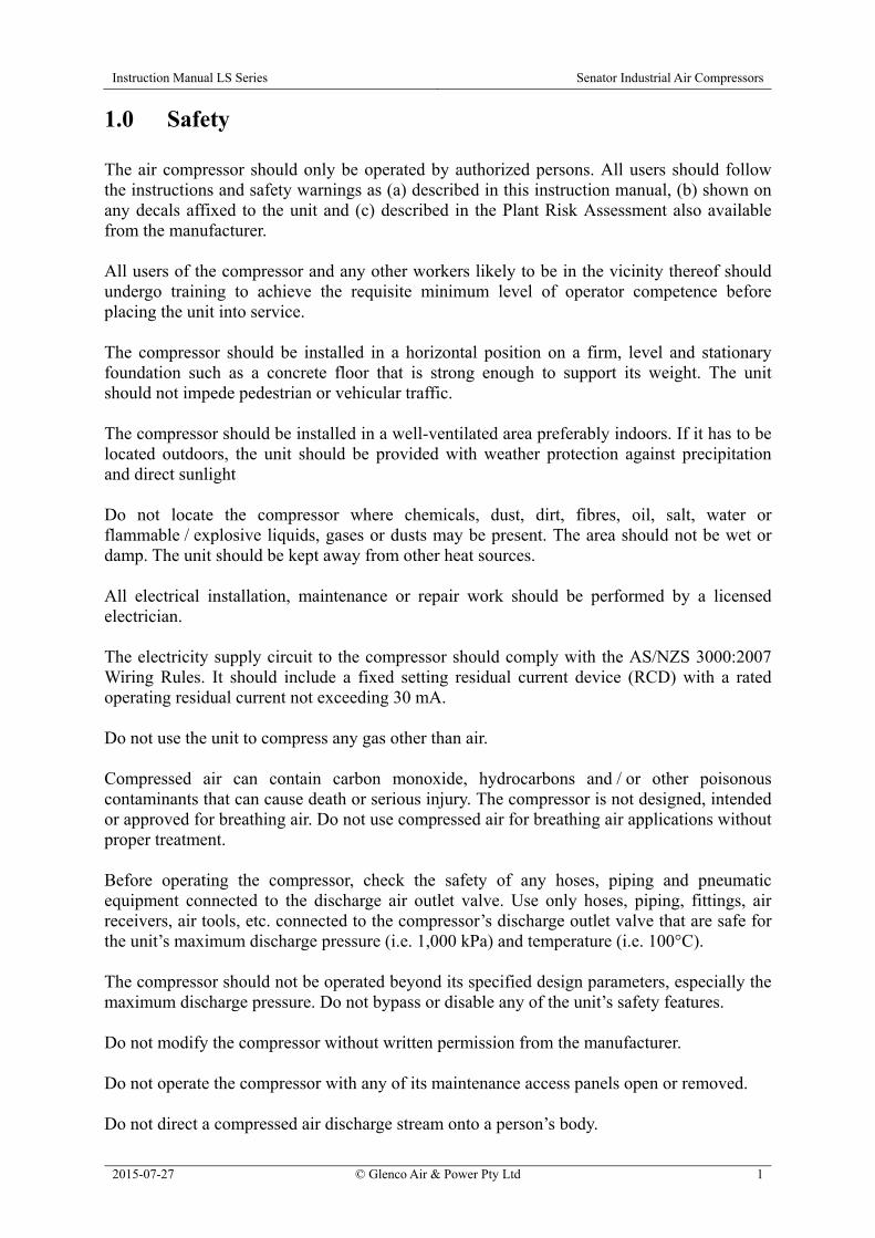
1.0 Safety The air compressor should only be operated by authorized persons. All users should follow the instructions and safety warnings as (a) described in this instruction manual, (b) shown on any decals affixed to the unit and (c) described in the Plant Risk Assessment also available from the manufacturer. All users of the compressor and any other workers likely to be in the vicinity thereof should undergo training to achieve the requisite minimum level of operator competence before placing the unit into service. The compressor should be installed in a horizontal position on a firm, level and stationary foundation such as a concrete floor that is strong enough to support its weight. The unit should not impede pedestrian or vehicular traffic. The compressor should be installed in a well-ventilated area preferably indoors. If it has to be located outdoors, the unit should be provided with weather protection against precipitation and direct sunlight Do not locate the compressor where chemicals, dust, dirt, fibres, oil, salt, water or flammable / explosive liquids, gases or dusts may be present. The area should not be wet or damp. The unit should be kept away from other heat sources. All electrical installation, maintenance or repair work should be performed by a licensed electrician. The electricity supply circuit to the compressor should comply with the AS/NZS 3000:2007 Wiring Rules. It should include a fixed setting residual current device (RCD) with a rated operating residual current not exceeding 30 mA. Do not use the unit to compress any gas other than air. Compressed air can contain carbon monoxide, hydrocarbons and / or other poisonous contaminants that can cause death or serious injury. The compressor is not designed, intended or approved for breathing air. Do not use compressed air for breathing air applications without proper treatment. Before operating the compressor, check the safety of any hoses, piping and pneumatic equipment connected to the discharge air outlet valve. Use only hoses, piping, fittings, air receivers, air tools, etc. connected to the compressor’s discharge outlet valve that are safe for the unit’s maximum discharge pressure (i.e. 1,000 kPa) and temperature (i.e. 100°C). The compressor should not be operated beyond its specified design parameters, especially the maximum discharge pressure. Do not bypass or disable any of the unit’s safety features. Do not modify the compressor without written permission from the manufacturer. Do not operate the compressor with any of its maintenance access panels open or removed. Do not direct a compressed air discharge stream onto a person’s body.

Instruction Manual LS Series Senator Industrial Air Compressors
2015-07-27 © Glenco Air & Power Pty Ltd 2
Monitor the compressor and downstream compressed air system for any excessive noise / vibration, leaks or other abnormalities and repair any faults immediately. Before performing any maintenance work on the compressor, switch off the unit, isolate and tag-out the power supply, carefully release any residual air pressure from the internal air-oil receiver and any connected downstream piping in the user’s network, and close the air outlet valve. And if possible, allow the unit to cool down if it’s been running. During maintenance work, take care to prevent any body parts, clothing or tools from touching any hot or moving components inside the compressor cabinet. The maintenance access panels should be handled as a two-person lift and stored in a horizontal position when removed. Carry out preventative maintenance on the compressor in accordance with the recommended schedule using only genuine spare parts. Clean up any oil leak discharge or oil spill immediately. Drain condensate from the air-oil receiver only when it is depressurized. Monitor the drained condensate to check whether it poses a slip hazard, e.g. excessive condensate discharged onto a smooth, non-porous floor. Clothing sleeves should be tight fitting, long hair should be tied back, jewellery and other loose articles should be removed, and loose gloves should not be worn when operating or maintaining the compressor. Wear body protection such as tight-fitting gloves, long sleeves and safety boots and also eye protection such as glasses when performing any maintenance work on the compressor. Wear eye protection such as glasses if working close to pressurized compressed air plant. Wear protection such as a filter respirator and goggles when blowing down with compressed air. Minimize the generation of dust by compressed air blowing. Wear appropriate eye, respiratory and body protection when spraying paint or other chemicals with compressed air. Refer to the chemical’s MSDS for specific personal protective equipment (PPE) recommendations.
Instruction Manual LS Series Senator Industrial Air Compressors
2015-07-27 © Glenco Air & Power Pty Ltd 3
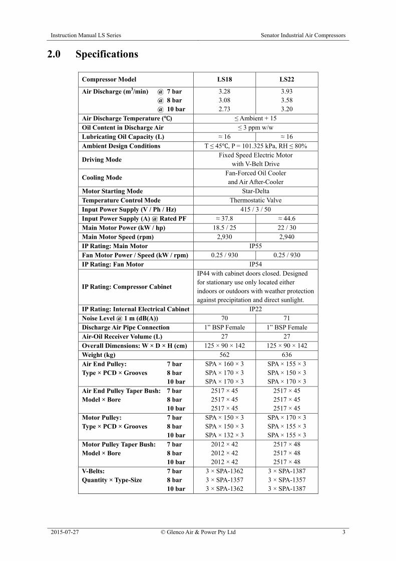
2.0 Specifications
Compressor Model LS18 LS22
Air Discharge (m3/min) @ 7 bar @ 8 bar @ 10 bar
3.28 3.08 2.73
3.93 3.58 3.20
Air Discharge Temperature ( ) ≤ Ambient + 15
Oil Content in Discharge Air ≤ 3 ppm w/w Lubricating Oil Capacity (L) ≈ 16 ≈ 16
Ambient Design Conditions T ≤ 45 , P = 101.325 kPa, RH ≤ 80%
Driving Mode Fixed Speed Electric Motor
with V-Belt Drive
Cooling Mode Fan-Forced Oil Cooler and Air After-Cooler
Motor Starting Mode Star-Delta Temperature Control Mode Thermostatic Valve Input Power Supply (V / Ph / Hz) 415 / 3 / 50 Input Power Supply (A) @ Rated PF ≈ 37.8 ≈ 44.6 Main Motor Power (kW / hp) 18.5 / 25 22 / 30 Main Motor Speed (rpm) 2,930 2,940 IP Rating: Main Motor IP55 Fan Motor Power / Speed (kW / rpm) 0.25 / 930 0.25 / 930 IP Rating: Fan Motor IP54
IP Rating: Compressor Cabinet
IP44 with cabinet doors closed. Designed for stationary use only located either indoors or outdoors with weather protection against precipitation and direct sunlight.
IP Rating: Internal Electrical Cabinet IP22 Noise Level @ 1 m (dB(A)) 70 71 Discharge Air Pipe Connection 1” BSP Female 1” BSP Female Air-Oil Receiver Volume (L) 27 27 Overall Dimensions: W × D × H (cm) 125 × 90 × 142 125 × 90 × 142 Weight (kg) 562 636 Air End Pulley: 7 bar Type × PCD × Grooves 8 bar 10 bar
SPA × 160 × 3 SPA × 170 × 3 SPA × 170 × 3
SPA × 155 × 3 SPA × 150 × 3 SPA × 170 × 3
Air End Pulley Taper Bush: 7 bar Model × Bore 8 bar 10 bar
2517 × 45 2517 × 45 2517 × 45
2517 × 45 2517 × 45 2517 × 45
Motor Pulley: 7 bar Type × PCD × Grooves 8 bar 10 bar
SPA × 150 × 3 SPA × 150 × 3 SPA × 132 × 3
SPA × 170 × 3 SPA × 155 × 3 SPA × 155 × 3
Motor Pulley Taper Bush: 7 bar Model × Bore 8 bar 10 bar
2012 × 42 2012 × 42 2012 × 42
2517 × 48 2517 × 48 2517 × 48
V-Belts: 7 bar Quantity × Type-Size 8 bar 10 bar
3 × SPA-1362 3 × SPA-1357 3 × SPA-1362
3 × SPA-1387 3 × SPA-1357 3 × SPA-1387
Instruction Manual LS Series Senator Industrial Air Compressors
2015-07-27 © Glenco Air & Power Pty Ltd 4
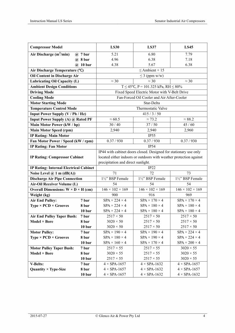
Compressor Model LS30 LS37 LS45
Air Discharge (m3/min) @ 7 bar @ 8 bar @ 10 bar
5.21 4.96 4.38
6.80 6.38 5.67
7.79 7.18 6.38
Air Discharge Temperature ( ) ≤ Ambient + 15
Oil Content in Discharge Air ≤ 3 (ppm w/w) Lubricating Oil Capacity (L) ≈ 30 ≈ 30 ≈ 30
Ambient Design Conditions T ≤ 45 , P = 101.325 kPa, RH ≤ 80% Driving Mode Fixed Speed Electric Motor with V-Belt Drive Cooling Mode Fan-Forced Oil Cooler and Air After-Cooler Motor Starting Mode Star-Delta Temperature Control Mode Thermostatic Valve Input Power Supply (V / Ph / Hz) 415 / 3 / 50 Input Power Supply (A) @ Rated PF ≈ 60.5 ≈ 73.2 ≈ 88.2 Main Motor Power (kW / hp) 30 / 40 37 / 50 45 / 60 Main Motor Speed (rpm) 2,940 2,940 2,960 IP Rating: Main Motor IP55 Fan Motor Power / Speed (kW / rpm) 0.37 / 930 0.37 / 930 0.37 / 930 IP Rating: Fan Motor IP54
IP Rating: Compressor Cabinet IP44 with cabinet doors closed. Designed for stationary use only located either indoors or outdoors with weather protection against precipitation and direct sunlight.
IP Rating: Internal Electrical Cabinet IP22 Noise Level @ 1 m (dB(A)) 71 72 73 Discharge Air Pipe Connection 1½” BSP Female 1½” BSP Female 1½” BSP Female Air-Oil Receiver Volume (L) 54 54 54 Overall Dimensions: W × D × H (cm) 146 × 102 × 169 146 × 102 × 169 146 × 102 × 169 Weight (kg) 900 916 969 Air End Pulley: 7 bar Type × PCD × Grooves 8 bar 10 bar
SPA × 224 × 4 SPA × 224 × 4 SPA × 224 × 4
SPA × 170 × 4 SPA × 180 × 4 SPA × 180 × 4
SPA × 170 × 4 SPA × 180 × 4 SPA × 180 × 4
Air End Pulley Taper Bush: 7 bar Model × Bore 8 bar 10 bar
2517 × 50 3020 × 50 3020 × 50
2517 × 50 2517 × 50 2517 × 50
2517 × 50 2517 × 50 2517 × 50
Motor Pulley: 7 bar Type × PCD × Grooves 8 bar 10 bar
SPA × 190 × 4 SPA × 180 × 4 SPA × 160 × 4
SPA × 190 × 4 SPA × 190 × 4 SPA × 170 × 4
SPA × 224 × 4 SPA × 224 × 4 SPA × 200 × 4
Motor Pulley Taper Bush: 7 bar Model × Bore 8 bar 10 bar
2517 × 55 3020 × 55 2517 × 55
2517 × 55 2517 × 55 2517 × 55
3020 × 55 3020 × 55 3020 × 55
V-Belts: 7 bar Quantity × Type-Size 8 bar 10 bar
4 × SPA-1657 4 × SPA-1657 4 × SPA-1657
4 × SPA-1632 4 × SPA-1632 4 × SPA-1632
4 × SPA-1657 4 × SPA-1657 4 × SPA-1632

Instruction Manual LS Series Senator Industrial Air Compressors
2015-07-27 © Glenco Air & Power Pty Ltd 5
Compressor Model LS55 LS75
Air Discharge (m3/min) @ 7 bar @ 8 bar @ 10 bar
10.30 9.58 9.04
13.05 12.33 11.18
Air Discharge Temperature ( ) ≤ Ambient + 15
Oil Content in Discharge Air ≤ 3 (ppm w/w) Lubricating Oil Capacity (L) ≈ 50 ≈ 50
Ambient Design Conditions T ≤ 45 , P = 101.325 kPa, RH ≤ 80%
Driving Mode Fixed Speed Electric Motor
with V-Belt Drive
Cooling Mode Fan-Forced Oil Cooler and Air After-Cooler
Motor Starting Mode Star-Delta Temperature Control Mode Thermostatic Valve Input Power Supply (V / Ph / Hz) 415 / 3 / 50 Input Power Supply (A) @ Rated PF ≈ 108 ≈ 144 Main Motor Power (kW / hp) 55 / 75 75 / 100 Main Motor Speed (rpm) 2,960 2,960 IP Rating: Main Motor IP55 Fan Motor Power / Speed (kW / rpm) 0.55 / 955 1.1 / 910 IP Rating: Fan Motor IP54 IP55
IP Rating: Compressor Cabinet
IP44 with cabinet doors closed. Designed for stationary use only located either indoors or outdoors with weather protection against precipitation and direct sunlight.
IP Rating: Internal Electrical Cabinet IP22 Noise Level @ 1 m (dB(A)) 73 74 Discharge Air Pipe Connection 2” BSP Female 2” BSP Female Air-Oil Receiver Volume (L) 100 100 Overall Dimensions: W × D × H (cm) 179 × 125 × 190 179 × 125 × 190 Weight (kg) 1,419 1,579 Air End Pulley: 7 bar Type × PCD × Grooves 8 bar 10 bar
SPB × 190 × 6 SPB × 200 × 6 SPB × 200 × 6
SPB × 180 × 6 SPB × 190 × 6 SPB × 200 × 6
Air End Pulley Taper Bush: 7 bar Model × Bore 8 bar 10 bar
3020 × 55 3020 × 55 3020 × 55
3020 × 55 3020 × 55 3020 × 55
Motor Pulley: 7 bar Type × PCD × Grooves 8 bar 10 bar
SPB × 160 × 6 SPB × 160 × 6 SPB × 150 × 6
SPB × 200 × 6 SPB × 200 × 6 SPB × 190 × 6
Motor Pulley Taper Bush: 7 bar Model × Bore 8 bar 10 bar
3020 × 60 3020 × 60 2517 × 60
3020 × 65 3020 × 65 3020 × 65
V-Belts: 7 bar Quantity × Type-Size 8 bar 10 bar
6 × SPB-1800 6 × SPB-1750 6 × SPB-1800
6 × SPB-1850 6 × SPB-1850 6 × SPB-1850

Instruction Manual LS Series Senator Industrial Air Compressors
2015-07-27 © Glenco Air & Power Pty Ltd 6
3.0 General Instructions 3.1 Overview The LS Series compressor sets are stationary, single-stage, oil-lubricated rotary screw type driven by a fixed speed electric motor. The compressor has an advanced micro-computer controller with an LCD display. It can efficiently reduce the power consumption and provide the operator with a convenient operation, monitoring and protection interface. A range of LS Series screw compressors is shown in Figure 3-1.
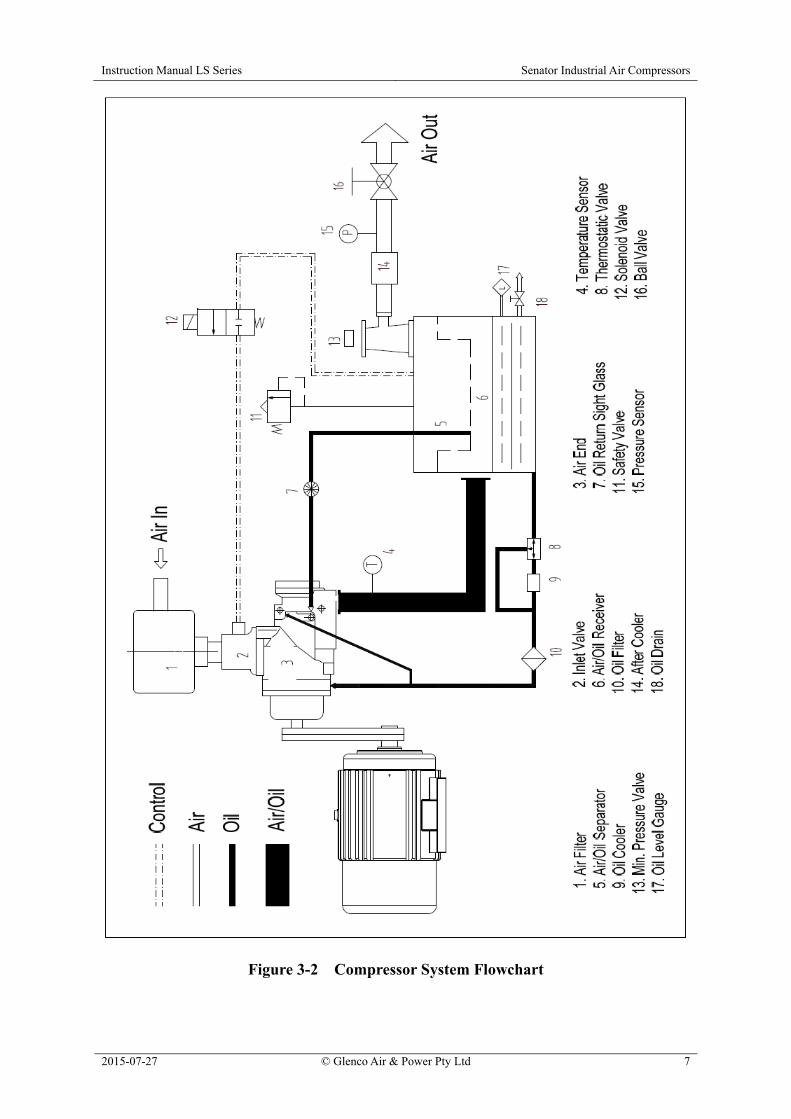
Figure 3-1 LS Series Rotary Screw Compressors 3.2 System Flowchart The compressor primarily consists of the rotary screw air end, electric motor, air-oil separator, oil system, cooling system, air system, electrical control system and other ancillary components. The system flow diagram of the unit is shown in Figure 3-2.
Instruction Manual LS Series Senator Industrial Air Compressors
2015-07-27 © Glenco Air & Power Pty Ltd 7
Figure 3-2 Compressor System Flowchart
Instruction Manual LS Series Senator Industrial Air Compressors
2015-07-27 © Glenco Air & Power Pty Ltd 8
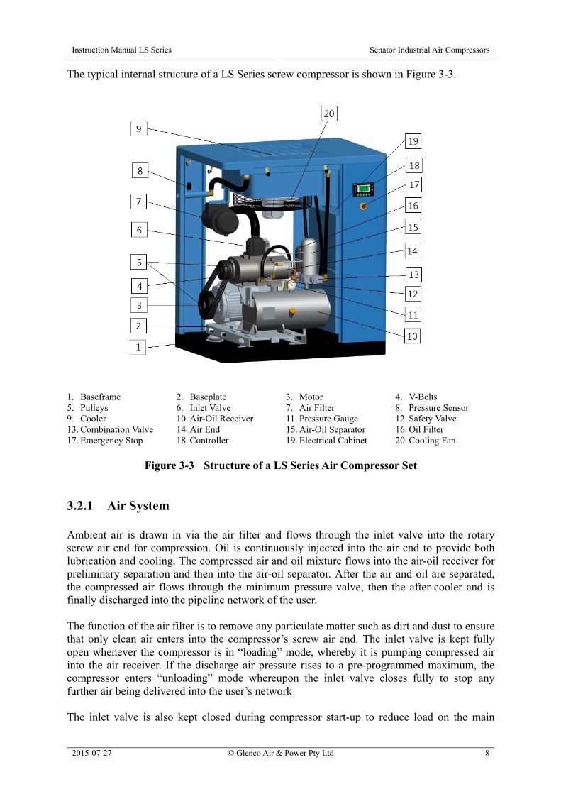
The typical internal structure of a LS Series screw compressor is shown in Figure 3-3.
1. Baseframe 2. Baseplate 3. Motor 4. V-Belts 5. Pulleys 6. Inlet Valve 7. Air Filter 8. Pressure Sensor 9. Cooler 10. Air-Oil Receiver 11. Pressure Gauge 12. Safety Valve 13. Combination Valve 14. Air End 15. Air-Oil Separator 16. Oil Filter 17. Emergency Stop 18. Controller 19. Electrical Cabinet 20. Cooling Fan
Figure 3-3 Structure of a LS Series Air Compressor Set
3.2.1 Air System Ambient air is drawn in via the air filter and flows through the inlet valve into the rotary screw air end for compression. Oil is continuously injected into the air end to provide both lubrication and cooling. The compressed air and oil mixture flows into the air-oil receiver for preliminary separation and then into the air-oil separator. After the air and oil are separated, the compressed air flows through the minimum pressure valve, then the after-cooler and is finally discharged into the pipeline network of the user. The function of the air filter is to remove any particulate matter such as dirt and dust to ensure that only clean air enters into the compressor’s screw air end. The inlet valve is kept fully open whenever the compressor is in “loading” mode, whereby it is pumping compressed air into the air receiver. If the discharge air pressure rises to a pre-programmed maximum, the compressor enters “unloading” mode whereupon the inlet valve closes fully to stop any further air being delivered into the user’s network The inlet valve is also kept closed during compressor start-up to reduce load on the main

Instruction Manual LS Series Senator Industrial Air Compressors
2015-07-27 © Glenco Air & Power Pty Ltd 9
motor. When the unit is shut down, the inlet valve is closed to prevent compressed air and oil flowing backwards from the air-oil receiver and being ejected through the air inlet. The minimum pressure valve ensures that the pressure in the air-oil receiver doesn’t fall below 0.35 MPa when the compressor is running so that the lubricating oil can flow normally in the system. When the compressor is running in unloading mode or shut down, the minimum pressure valve prevents the compressed air in the pipeline network of the user from flowing backwards into the unit. An automatic vent valve is located beside the inlet valve. The vent valve automatically opens to release air pressure from the air-oil receiver whenever the compressor is in unloading mode or shut down. 3.2.2 Lubrication System The compressed air and oil mixture is injected into the air-oil receiver and collides with its inner wall. Most of the lubricating oil is separated from the air-oil mixture during this process and accumulates in the lower part of the air-oil receiver. The remaining oil is captured by the air-oil separator and transferred back to the screw air end via the oil return pipe. During compressor operation, when the temperature of the lubricating oil is below 83°C the thermostatic valve automatically opens the bypass circuit and the circulating oil from the air-oil receiver is directly injected under air pressure into the screw air end and individual lubricating points via the oil system piping and oil filter. When the temperature rises above 83°C, the thermostatic valve gradually shuts off the bypass circuit and simultaneously opens the circuit going to the oil cooler. If the temperature rises to 95°C, the bypass circuit is completely shut off and the entire lubricating oil flow from the air-oil receiver is passed through the oil cooler circuit on its way back to the air end. The functions of the thermostatic valve are to (a) maintain constant temperature and viscosity of lubricating oil, (b) enable the system to reach the optimal operating temperature as soon as possible and (c) maintain sufficient temperature to prevent water vapour in the system from condensing. The function of the lubricating oil filter is to remove any metal wear particles and lubricating oil cracking products so as to minimize wear of the air end bearings and rotors. 3.2.3 Cooling System Cooling air is drawn from outside the unit by the cooling fan and then blown across the radiator fins of the combined oil cooler and air after-cooler. Heat exchange takes place between the cooling air and the hot oil and compressed air streams to achieve a cooling effect. The maximum ambient air temperature should not exceed 45°C otherwise excessively high compressed air and oil temperatures will occur; this will shorten the life of the lubricating oil and may activate over-temperature shutdown of the compressor.
Instruction Manual LS Series Senator Industrial Air Compressors
2015-07-27 © Glenco Air & Power Pty Ltd 10
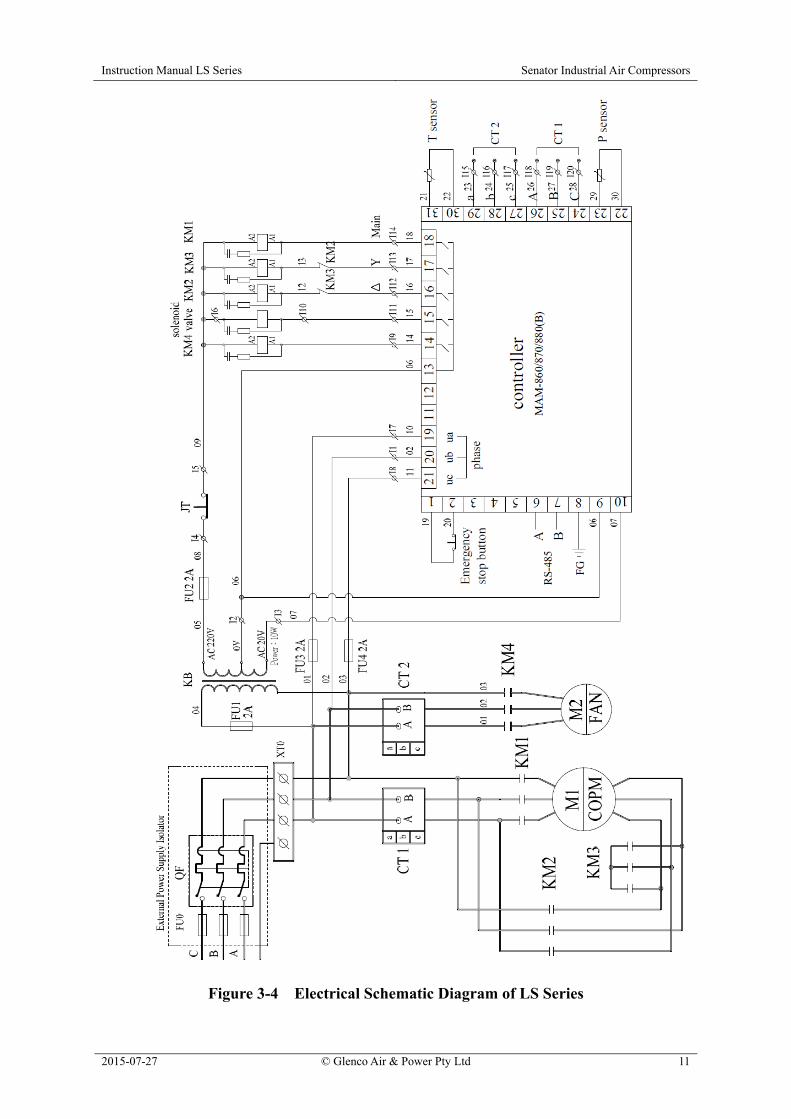
3.3 Control Protection System The compressor has a micro-computer controller which automatically adjusts the operating state of the unit according to the actual air consumption of the user’s application. If the air consumption is low or the air application is paused, the inlet valve will close allowing the compressor to operate with reduced energy consumption in unloading mode. After the air consumption is recommenced, the controller opens the inlet valve again to enable the compressor to operate normally in loading mode. The controller monitors the compressor at all times when it’s running. If any abnormal condition – such as motor overload, air discharge over-temperature, etc. – is detected, the controller automatically shuts down the compressor to protect it against damage. A safety valve is installed in the air-oil receiver. If the pressure inside the receiver exceeds its design rating, the safety valve will automatically open to quickly discharge the air and reduce the pressure, thereby ensuring safety of the unit and personnel. The safety valve should not open during normal operation. 3.4 Electrical System The electrical system consists primarily of the main motor, fan motor, electrical control cabinet assembly, solenoid valve, temperature sensor, pressure sensor and controller. To protect the main and fan motors against overheating damage due to abnormal conditions, their operating current draws are monitored by the controller. If the motor current exceeds the allowable current, the compressor controller will perform an immediate shutdown and the motor overload alarm message will be shown on the controller’s display panel. The electrical schematic diagram is shown in Fig 3-4. 3.5 Compressor Controller and Operation Panel The compressor is fitted with an advanced micro-computer controller with built-in user interface. The controller handles the automatic operation, monitoring and protection of the compressor’s functions. To ensure normal and safe operation of the compressor, users should be familiar with the functions and meanings of the individual buttons, display messages and indicating lights on the controller. Please refer to the separate MAM-870 Controller Instruction Manual in Appendix A for complete details.
Instruction Manual LS Series Senator Industrial Air Compressors
2015-07-27 © Glenco Air & Power Pty Ltd 11
Figure 3-4 Electrical Schematic Diagram of LS Series

Instruction Manual LS Series Senator Industrial Air Compressors
2015-07-27 © Glenco Air & Power Pty Ltd 12
4.0 Installation 4.1 Outline Dimensions
Model A B C D E F G H I J
LS18-22 1,245 900 1,415 433 482 860 1,075 75 200 198
LS30-45 1,456 1,020 1,690 440 650 980 1,407 80 284 252
Model A B C D E F G H I J
LS55-75 1,790 1,250 1,900 620 700 1,210 1,578 90 430 380
Figure 4-1 Outline Dimensions of LS Series (in mm)
4.2 Installation Site of Compressor A proper installation site should be selected for the compressor. It is recommended to use a dedicated compressor room. The installation site should meet the following requirements:
a. It is essential to install the compressor in an area with good lighting and sufficient free space for unhindered operation and maintenance. The compressor should have clearance of no less than 0.6 m around all four sides. The ceiling height should be at least 2.4 m from floor level.

Instruction Manual LS Series Senator Industrial Air Compressors
2015-07-27 © Glenco Air & Power Pty Ltd 13
b. Good ventilation is essential to ensure that the indoor ambient temperature is kept to a minimum; it should never exceed 45°C. If the compressor room is mechanically ventilated, the cooling airflow should be at least 750 m3/h per kW of nominal compressor motor power. So the requisite cooling airflow to suit a LS37 compressor, for example, would be at least 37 × 750 = 27,750 m3/h.
c. The ambient air should be reasonably clean and free of solid and gaseous
contamination. It should have low relative humidity, low dust content and no corrosive, explosive or inflammable substances present. If the air quality fails to reach these requirements, it will be necessary to provide clean air entry to the compressor room from a remote source or install pre-filtration equipment.
d. The compressor should be installed in a horizontal position on a solid, flat
foundation. Mounting holes are provided in the compressor’s baseframe through which it should be affixed to the floor with hold-down fasteners. The unit is designed for stationary duty only.
e. If it has to be located outdoors, the compressor should be provided with weather
protection against precipitation and direct sunlight. 4.3 Electricity Supply
Air Compressor
Model
Main Motor Rating (kW)
Main Motor
Starting Method
Maximum Running Current
(A)
Minimum Circuit Breaker Rating
(A)
Circuit Breaker Tripping
Curve
LS18 18.5 Star-Delta 37.8 50 C or D LS22 22 Star-Delta 44.6 63 C or D LS30 30 Star-Delta 60.5 80 C or D LS37 37 Star-Delta 73.2 100 C or D LS45 45 Star-Delta 88.2 125 C or D LS55 55 Star-Delta 108 160 C or D LS75 75 Star-Delta 144 200 C or D
a. The compressor requires a three-phase mains power supply stabilized at 415 Volts and 50 Hertz. A portable electric generator is not recommended for powering the compressor unless it has ample generating capacity to supply both the requisite starting and running current demands without appreciable voltage or frequency drop.
b. All electrical installation work must be performed by a licensed electrician in
accordance with the AS/NZS 3000:2007 Wiring Rules.
c. A separate electricity supply circuit is recommended for the compressor to avoid motor current overload due to excessive voltage drop or an unbalanced three-phase condition caused by other electrical equipment operating in parallel.
Instruction Manual LS Series Senator Industrial Air Compressors
2015-07-27 © Glenco Air & Power Pty Ltd 14
d. For additional protection against electric shock, it is recommended to include a fixed setting residual current device (RCD) with rated operating residual current not exceeding 30 mA. Special RCDs should be considered for use with high current or variable speed drives (VSDs) to prevent nuisance tripping.
e. The circuit breaker information provided in the table above is a general guide only
for dedicated supply to the compressor. A four-wire conductor is required for the electricity supply, i.e. three-phase and earth only (no neutral).
f. The maximum running current may exceed the specified value in practice if the
electricity supply voltage and/or power factor are below their rated levels.
g. If the initially connected phase sequence is incorrect, the compressor’s controller will annunciate a “PHASE REVERSE” failure. The direction of air end rotation should also be double-checked during installation by performing a “bump” test with reference to the direction-of-rotation arrow marked permanently on the air end.

Instruction Manual LS Series Senator Industrial Air Compressors
2015-07-27 © Glenco Air & Power Pty Ltd 15
5.0 Operation Before compressor start-up, the operator should thoroughly read and understand this manual and familiarize him or her-self with the compressor’s features. The operator should comply with all of the instructions and especially the safety notices. 5.1 Initial Start-Up a. Remove the compressor from its timber crate and shipping skid. Use a forklift only to lift
the compressor by means of the fork blade pockets in the baseframe. Caution: The unit’s centre-of-gravity is offset towards the left hand side of models LS18-45 and the right hand side of models LS55-75 when viewed looking onto the front (controller) side.
b. Remove the two red shipping brackets attached between the baseframe and baseplate as shown in Figure 5-1.
Figure 5-1 Shipping Brackets
c. Connect the power supply cable and the earth cable (if separate). Check that the voltage is correct and equal on all three phases.
d. Check whether the electrical wiring is safe, secure and reliable.
e. Check whether the oil level in the air-oil receiver is OK.
f. Check whether the V-belt tension is correct.
g. Before start-up after three or more months of shutdown or storage, add about 0.5 L of
clean compressor lubricating oil directly into the compressor through the air inlet valve and then rotate the screw air end for several turns by hand. This is to prevent friction / heat damage to the screw air end due to insufficient lubrication upon initial start-up.
h. At the first power-on, the power supply indicator light on the control panel will be

Instruction Manual LS Series Senator Industrial Air Compressors
2015-07-27 © Glenco Air & Power Pty Ltd 16
illuminated and the current pressure in the air tank will be displayed on the control panel. If the phase sequence rotation of the power supply is incorrect, the controller will display “PHASE REVERSE”. A licensed electrician must then reverse the phase sequence rotation by interchanging any two phases of the power supply connection.
i. Open the air outlet valve.
j. Rotation direction test: Although the compressor has built-in reverse phase sequence
protection, the rotation direction test is still an important step in the initial start-up. It should also be carried out whenever the motor is repaired or replaced.
k. Press the Start button and then immediately press the Emergency Stop button when
the motor shaft begins to rotate. Make sure that the rotation direction of the motor is consistent with the direction arrow marked on the air end. If it is incorrect, the phase rotation sequence of the power supply must be reversed by a licensed electrician. The rotation direction of the fan motor should also be checked; the cooling air should discharge through the oil cooler / air after-cooler and upwards from the exhaust vents on top of the unit. After completing these checks and making any necessary adjustments, release the Emergency Stop button by turning it clockwise.
l. Restart the compressor. The unit will automatically commence operating. Stop or limit
any downstream compressed air use so that the system pressure can rise until the unit switches to unloading mode. Check whether the unloading pressure is consistent with the pre-programmed setting and observe whether the controller shows all monitored parameters are within their normal ranges. If any abnormal sound, vibration or leakage occurs, immediately press the Emergency Stop button to shut down the machine for inspection.
m. Shutdown: Press the Stop button . The unit will enter the unloading mode and the
compressor vent valve will discharge the internal system air. After 30 seconds, the unit will stop. During normal operation, do not use the Emergency Stop button to shut down the compressor.
5.2 Daily Operation 5.2.1 Start-Up a. Remove the plug and carefully open the ball valve at the bottom of the air-oil receiver to
drain out any water condensate. Close the drain valve immediately when lubricating oil starts to flow out and then re-install the plug. This task should be undertaken when the unit is cold prior to use. Caution: Ensure the air-oil receiver is not pressurized before removing the plug and opening the ball valve.
b. Open the air outlet valve on the side of the compressor cabinet.
c. Start-up any peripheral compressed air equipment such as an air dryer.

Instruction Manual LS Series Senator Industrial Air Compressors
2015-07-27 © Glenco Air & Power Pty Ltd 17
d. Press the Start button on the compressor.
e. After the operation is in steady state, check the discharge pressure and temperature readings. The pressure should remain within the limits of the “loading” and “unloading” pressure settings provided that the compressor and / or the air storage capacity is large enough for the application. The temperature will typically vary between 83 and 95°C depending upon the unit’s operating conditions, and should not exceed 104°C.
f. Ensure that the pre-maintenance safety precautions described in Section 1.0 are taken
before checking the compressor’s oil level in accordance with the instructions given in Section 6.0.
g. If any abnormal condition is found, turn off and isolate the compressor for inspection.
Only restart the unit after rectifying the problem. 5.2.2 Operating Modes Starting Press the Start button . The contactor in the electrical cabinet will close to start the main drive motor. At this point, the throttle in the inlet valve will be closed, and only a low volume of air enters into the compressor through the check valve in the inlet valve. The compressor starts at reduced load and then the preliminary system pressure gradually increases in the air-oil receiver. Loading 10 seconds after starting, the solenoid actuated inlet valve opens fully so that a high volume of air can enter into the compressor to enable “loading” mode operation. When the pressure inside the air-oil receiver reaches 0.35 MPa, the minimum pressure valve opens and the unit starts to discharge into the user’s compressed air system. Unloading If the user’s air consumption remains continuously below the compressor’s minimum discharge flowrate, the discharge pressure of the unit will reach the set unloading pressure. At this point, the inlet valve closes to stop air input. The check valve spool of the minimum pressure valve is closed to isolate the compressor from the pipeline of the user. The vent valve opens to reduce the pressure in the air-oil receiver down to approximately 0.4 MPa, thereby reducing the operating back pressure within the compressor’s air circuit and maintaining lubricating oil circulation. In unloading mode, if the discharge pressure reduces to the loading pressure set point, the controller actuates the solenoid to open the inlet valve and close the vent valve. The unit is thus returned to the loading operation state. If the unit fails to stop loading operation at the correct unloading set point pressure, it may
Instruction Manual LS Series Senator Industrial Air Compressors
2015-07-27 © Glenco Air & Power Pty Ltd 18
cause the safety valve installed in the air-oil receiver to open for system pressure relief, thereby avoiding any hazard due to excessively high system pressure. If this occurs, immediately shut down the unit and check the inlet valve and controller for their correct operation and setting. Stand-By If the compressor operates continuously in unloading mode for five minutes, the controller assumes that the user has ceased air consumption and switches the compressor to stand-by mode. The main motor and fan motor will stop rotating to save energy. In stand-by mode, if air consumption is resumed and pressure at the air outlet decreases to the loading set point, the controller will restart the unit automatically.
Caution: The controller’s display will indicate “STANDBY” whenever the compressor is in stand-by mode. In such a state, the compressor cabinet doors should not be opened and no maintenance work should be carried out due to the risk of injury if the unit restarts automatically. 5.2.3 Shutdown Normal Shutdown If compressed air is no longer required, for example at lunchtime or end of the working day, pressing the Stop button will initiate the compressor’s normal shutdown sequence. The unit will either switch to or remain in unloading mode for 30 seconds to stabilize the internal air and oil systems before ceasing operation altogether. After a further 60 seconds, the unit can only be restarted by pressing the Start button . After shutdown, the air outlet valve should be closed to protect the unit against the influence of compressed air in the external pipeline network. Fault Alarm Shutdown If any electrical, pressure or temperature fault is detected, the controller will shut down the compressor immediately. If this happens, the fault should be investigated and rectified according to the indication on the controller’s display panel. Press and hold the controller’s Return / Reset button marked “C” for 5 seconds to reset the compressor after rectifying the fault or alternatively switch off the mains electricity supply for one minute. Emergency Shutdown If any abnormal condition arises during compressor operation, press the Emergency Stop button immediately for direct shut down of the unit to avoid any damage or injury. The fault should then be investigated and rectified before resetting the controller.

Instruction Manual LS Series Senator Industrial Air Compressors
2015-07-27 © Glenco Air & Power Pty Ltd 19
5.2.4 Monitoring During Operation a. Observe whether the compressor is emitting any abnormal noise or vibration. If present,
an immediate shutdown should be performed. b. Do not loosen any pipes, bolts, threaded joints or electrical connections in the compressor
when it’s switched on or running. Any individual valves in the unit shouldn’t be opened or closed at random.
c. Observe the oil level. If the oil level is too low and not in the green zone on the oil level
gauge, shut down the compressor and top-up the oil level. d. The operator on each shift should keep a written log recording the discharge pressure,
discharge temperature, motor currents, oil level, run time, etc. and any maintenance or repair work carried out on the compressor.
5.2.5 Duty Cycle The compressor is ideally suited for applications with a continuous compressed air demand in the vicinity of 100% of the unit’s rated free air delivery. During periods of very low air demand, the unit may not reach its normal operating temperature with sufficient frequency or duration. Sustained operation at very low duty cycle can result in a build-up of water condensate within the lubricating oil. If this occurs, the lubricating characteristics of the oil can be impaired and this may cause serious internal damage to the unit. The compressor should be allowed ample running time in loading mode of at least 10 minutes per hour when in use to prevent such accumulation of condensate in the lubricating oil. 5.3 Long-Term Shutdown 5.3.1 Preparation If the compressor is to be shut down for longer than one month, the following steps should first be performed: a. Any faults should be rectified in preparation for the unit’s future use. b. The water condensate in the air-oil receiver should be completely drained out to prevent
internal corrosion. c. All openings should be enclosed with plastic cloth or oiled paper to prevent the ingress of
moisture and dust. If the unit is to be out of service for more than two months, replace the lubricating oil beforehand and then run the compressor for 30 minutes. After three days, the water
Instruction Manual LS Series Senator Industrial Air Compressors
2015-07-27 © Glenco Air & Power Pty Ltd 20
condensate in the air-oil receiver should be completely drained out. 5.3.2 Restart a. Remove the protective plastic cloth or oiled paper. b. Measure the insulation resistance of motors to ground, which should be more than 1 MΩ. c. Follow the initial start-up procedure described in Section 5.1 to restart the unit.
Instruction Manual LS Series Senator Industrial Air Compressors
2015-07-27 © Glenco Air & Power Pty Ltd 21
6.0 Maintenance Before performing any maintenance work on the compressor, switch off the unit, isolate and tag-out the power supply, carefully release any residual air pressure from the internal air-oil receiver and any connected downstream piping in the user’s network, and close the air outlet valve. And if possible, allow the unit to cool down if it’s been running. 6.1 Lubricating Oil The lubricating oil has a critical effect on the performance and service life of a rotary screw air compressor. If incorrect lubricating oil is used, it will cause severe damage to the compressor. Either of the following compressor lubricating oils is recommended: Option 1: Compressor Oil – Mineral Based Brand: Castrol Product: AIRCOL PD46 Service Life: Up to 2,000 Hours Option 2: Synthetic Compressor Oil - Polyalphaolefin Based Brand: Castrol Product: AIRCOL SR46 Service Life: Up to 8,000 Hours Equivalent premium grade compressor oils from other suppliers may be substituted. Caution: Use only one or the other of the above recommended oil types. Do not use a mixture of mineral and synthetic oils. 6.1.1 Oil Change Interval a. The initial oil change should be performed after the compressor operates for about 500
running hours or 3 months, whichever occurs first. b. If mineral-based lubricating oil is used, it should be replaced every 1,000 to 2,000 hours.
If synthetic-based oil is used, it should be replaced every 4,000 to 8,000 hours. In either case, the lubricating oil should be replaced at least every 12 months if not sooner according to the running hours limit.
c. If an oil sample analysis indicates that the lubricating oil needs to be changed, it should be
done promptly.
d. If the operating conditions are poor and the discharge temperature is often 95°C or higher, the oil change period should be halved.
Instruction Manual LS Series Senator Industrial Air Compressors
2015-07-27 © Glenco Air & Power Pty Ltd 22
6.1.2 Replacing Oil a. Press the Stop button and then switch off, isolate and tag-out the power supply to the
compressor.
b. Close the air outlet valve.
c. Wait at least two minutes for the pressure in the air-oil receiver to be completely released and monitor the pressure gauge to confirm. Slowly open the screw-plug at the oil filling port and then rotate the air end pulley by hand about 10 turns in the forward direction as marked on the air end.
d. Remove the plug from the outlet of the oil drain ball valve and then open the valve to
drain out the lubricating oil from the air-oil receiver. Collect the drained lubricating oil in a suitable container and properly dispose of it to prevent any environmental pollution.
e. Close the oil drain ball valve and reinstall the oil drain plug. Fill the air-oil receiver with
lubricating oil until the oil level reaches the upper limit of the green zone on the oil level gauge. Reinstall and tighten the screw-plug in the oil filling port.
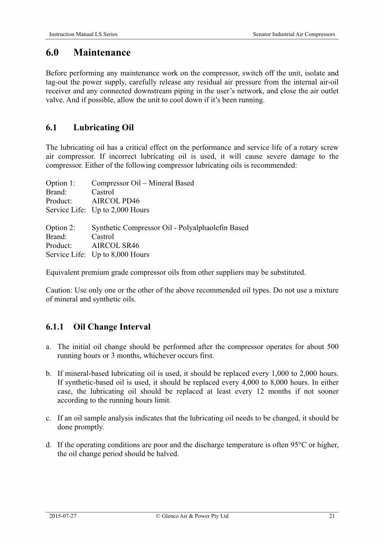
f. Restart the compressor and allow it to operate in loading mode until the discharge
temperature reaches at least 85°C and then shut down the unit. Wait five minutes and re-check the oil level. Top-up if necessary until the oil level is at the top-dead-centre mark on the gauge as shown in Figure 6-1.
g. Reset the “LUBE” hours to zero via the user set parameters menu of the controller.
Figure 6-1 Full Oil Level Indication 6.2 Oil Filter Initial replacement of the oil filter should be performed after the compressor operates for 500 hours or 3 months, whichever occurs first. Subsequent replacement is required every 1,000 hours or 12 months. If the lubricating oil needs to be replaced, the oil filter should be replaced at the same time. If the operating conditions are poor and the discharge temperature is often 95°C or higher, the oil filter replacement period should be halved.
Instruction Manual LS Series Senator Industrial Air Compressors
2015-07-27 © Glenco Air & Power Pty Ltd 23
The replacement steps are as follows: a. Press the Stop button and then switch off, isolate and tag-out the power supply to the
compressor.
b. Close the air outlet valve.
c. Wait at least two minutes for the pressure in the air-oil receiver to be completely released and monitor the pressure gauge to confirm.
d. Use an oil filter wrench to remove the oil filter by unscrewing it anticlockwise. e. Clean the sealing washer of the new oil filter and then apply a thin layer of clean
lubricating oil onto it. f. Install the new oil filter by screwing it on clockwise until the sealing washer contacts the
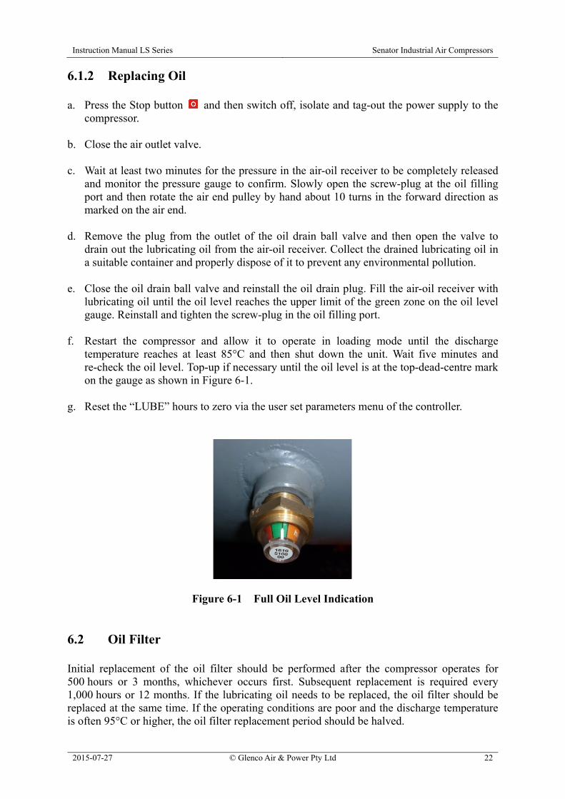
oil filter base and then tighten it by hand a further ½ to ¾ of a turn. g. Reset the “OIL FILTER” hours to zero via the user set parameters menu of the controller. 6.3 Air-Oil Separator The air-oil separator should be replaced after every 2,000 hours or 1 year, whichever occurs first. In a dirty or dusty environment, the replacement period should be halved. It is not possible to clean the air-oil separator element, only replacement is allowed. The procedure for replacing the air-oil separator is essentially the same as that described above for replacing the oil filter. Caution: When removing the air-oil separator, the separator connector may become partly or wholly unscrewed from its base. Use a spanner to check and tighten the separator connector if necessary, taking care not to damage its sealing O-ring. Caution: When replacing the air-oil separator, it is essential to prevent ingress of foreign matter into the air-oil receiver. After replacing the air-oil separator, reset the “O-A FILTER” hours to zero via the user set parameters menu of the controller. 6.4 Air Pre-Filters The air pre-filters are accessed by removing the compressor’s side panels. Refer to Figure 6-2. Wash the foam elements in warm, soapy water and then rinse clean. Do not use any solvents or chemical cleaners. Shake the foam elements to remove excess water and then blow dry using compressed air or allow to dry naturally before re-installation. Do not operate the unit with the air pre-filters or
Instruction Manual LS Series Senator Industrial Air Compressors
2015-07-27 © Glenco Air & Power Pty Ltd 24
side panels removed.
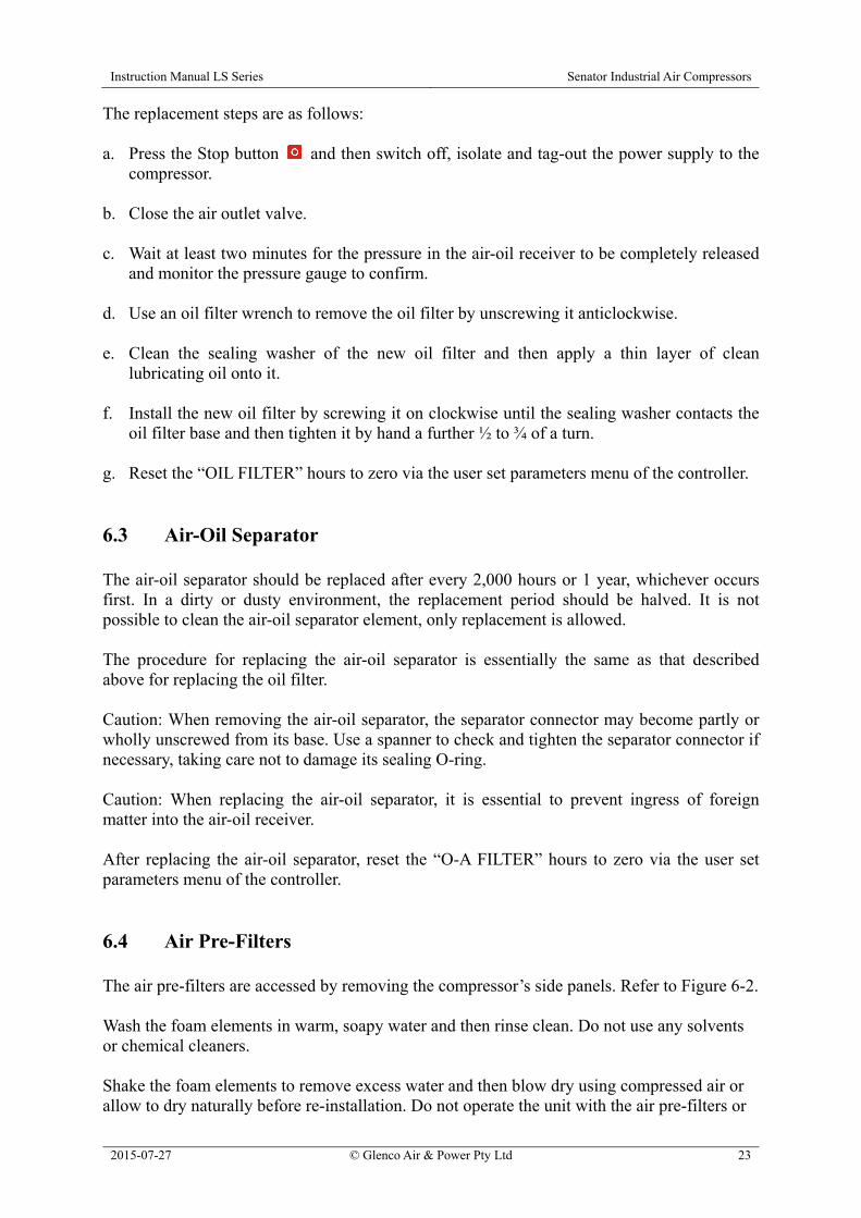
Figure 6-2 Air Pre-Filters Location and Removal 6.5 Air Filter a. After removal from the air filter assembly and working at a distance of at least 5 m from
the compressor, the air filter element can be blown clean from the inside to the outside using compressed air at a pressure no higher than 500 kPa. Refer to Figure 6-3. Keep the air blowing outlet more than 20 mm away from the inner surface of the filter element. After the air filter element is cleaned 3 to 4 times, it should be replaced.
b. Do not hit the air filter element to shake free any dust nor clean it with water or any other
liquid. If the filter element is damaged, it should be replaced. If the filter element is oily or contaminated severely, no cleaning is practicable and the element should be replaced.
Figure 6-3 Air Filter Element Cleaning c. The maximum service life of the air filter element is 2,000 hours. If the operating
conditions of the compressor are adverse (i.e. dusty or dirty), then the replacement period should be halved.
Instruction Manual LS Series Senator Industrial Air Compressors
2015-07-27 © Glenco Air & Power Pty Ltd 25
d. After replacing the air filter element, reset the “AIR FILTER” hours to zero via the user set parameters menu of the controller.
6.6 Oil Cooler and Air After-Cooler If the air discharge temperature from the compressor is excessively high, the combined oil cooler and air after-cooler mounted at the top of the compressor cabinet should be blown off with clean compressed air to remove any dirt or dust. If it can’t be cleaned in this manner, then wash it with a proper cleaning agent. Never use a metal wire brush or metal scraper to remove the dirt or dust. The finned cooler should be kept clean and free of any obstructions at all times. The underside of the finned cooler can be accessed for cleaning or inspection via removable panels on two sides of the cooling fan plenum. 6.7 Safety Valve Check the safety valve on the air-oil receiver regularly to verify that it’s operating freely. While the receiver is pressurized to at least 650 kPa (94 psi), pull the ring on the safety valve and allow it to snap back to its normal position. If air leaks out after the ring has been released, or the valve is stuck and cannot be actuated by pulling the ring, the safety valve is faulty and must be replaced before operating the compressor. Caution: Take care when testing the safety valve as compressed air will discharge from the valve with high velocity. Caution: Do not tamper with the safety valve. It is designed to automatically release air if the receiver pressure exceeds the safety valve’s pressure setting. 6.8 V-Belts a. Check the condition and tension of the V-belts after the compressor operates for about 500
running hours or 3 months, whichever occurs first, and thereafter each 1,000 running hours or 1 year. If correctly tensioned, a force of 40 N (4 kg) applied mid-span on a single V-belt should cause it to deflect about 8 mm (≈ 5/16 inch).
b. It is essential to use replacement V-belts with the correct specifications. Replace all
V-belts simultaneously and do not mix belts from different manufacturers. Also, do not mix new and used V-belts.
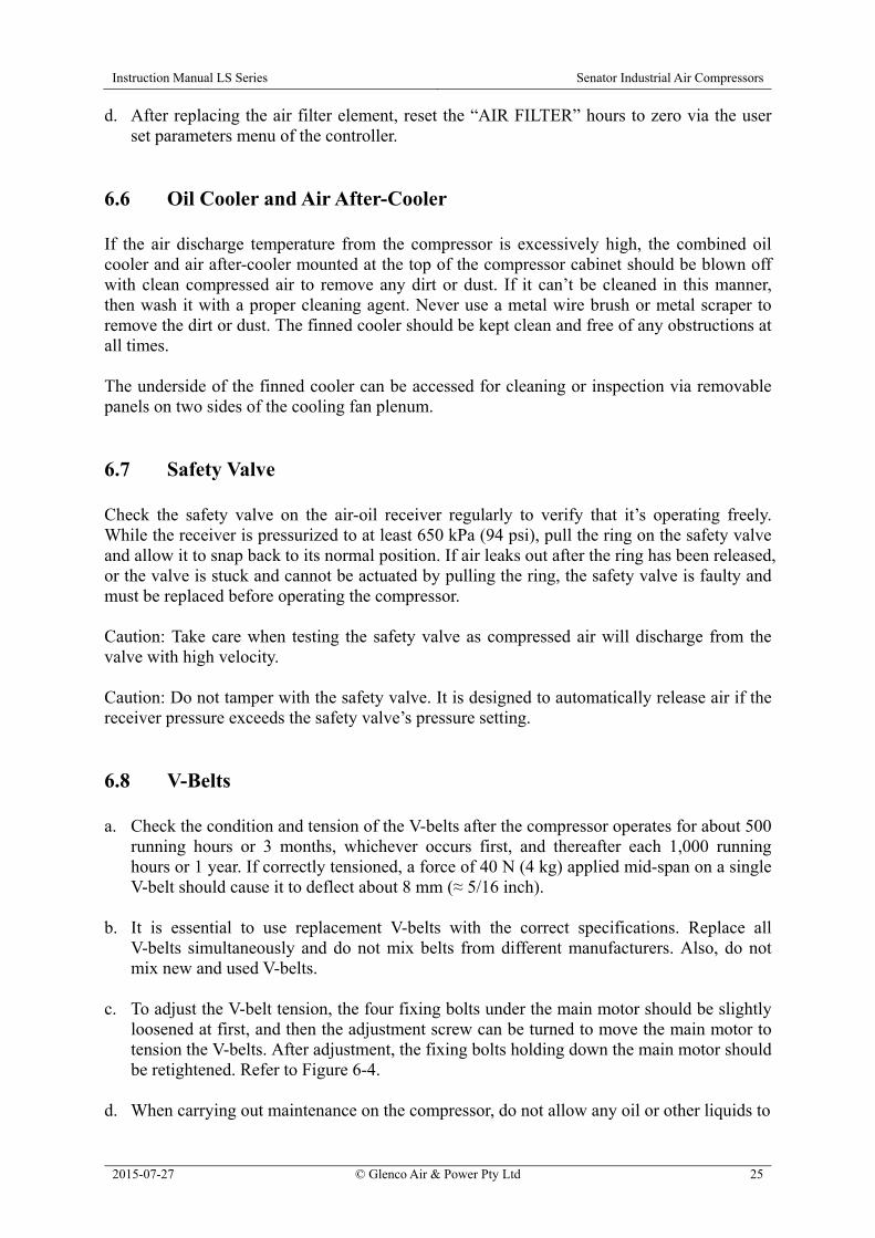
c. To adjust the V-belt tension, the four fixing bolts under the main motor should be slightly
loosened at first, and then the adjustment screw can be turned to move the main motor to tension the V-belts. After adjustment, the fixing bolts holding down the main motor should be retightened. Refer to Figure 6-4.
d. When carrying out maintenance on the compressor, do not allow any oil or other liquids to
Instruction Manual LS Series Senator Industrial Air Compressors
2015-07-27 © Glenco Air & Power Pty Ltd 26
splash onto the V-belts or pulleys to prevent belt slippage.
Figure 6-4 V-Belt Tension Adjustment 6.9 Motor Bearings The main motor’s drive end (DE) and non-drive end (NDE) bearings should be re-greased at least every 2,000 hours or 1 year, whichever occurs first. Mobil Polyrex EM grease or equivalent is recommended. Do not mix different types of grease. This maintenance task is best undertaken when the motor is still warm to allow for better dispersion of the grease. a. Locate the grease nipple on top of each DE and NDE bearing and also the grease drain
plug underneath (that may be offset to one side). Refer to Figure 6-5. It is often necessary to temporarily remove the motor fan cowl on the non-drive end to access these points.
b. Remove the drain plug and clean old grease from the drain opening. c. Clean the grease nipple and grease gun nozzle to prevent contaminants entering into the
bearing. d. Using a hand operated grease gun, pump the requisite quantity of grease in through the
nipple as specified on the motor bearing data nameplate. e. Operate the compressor for 10 to 30 minutes with the drain plug removed to allow any
excess grease to vent out through the drain.
f. Shut down the compressor and make it safe to work on again. Then clean up any expelled grease from the drain outlet and re-install the plug.

Instruction Manual LS Series Senator Industrial Air Compressors
2015-07-27 © Glenco Air & Power Pty Ltd 27
Figure 6-5 Motor Bearing Re-Greasing 6.10 Electrical Cabinet The compressor’s electrical cabinet and the components housed therein should be checked and cleaned by a licensed electrician every 2,000 hours or 1 year, whichever occurs first. The external and internal surfaces of the electrical cabinet should be vacuum cleaned and wiped down with a dry cloth. The electrical components and wiring within the cabinet should be vacuum cleaned only with particular attention given to the cabinet’s louvre vents. 6.11 Preventative Maintenance Program
Maintenance Task Maintenance Interval *
8 h 40 h 500 h 1,000 h 2,000 h 4,000 h 8,000 h Daily Weekly Qtrly 1 Year 2 Years
Routine Operation
Check / Top-Up Oil Level Drain Air-Oil Receiver Condensate Check Controller and Gauge Readings
Air System
Clean Air Pre-Filters Clean Air Filter Element Clean Oil Cooler and Air After-Cooler
Check Safety Valve Replace Air Filter Element Replace Inlet Valve Maintenance Kit
Replace Minimum Pressure Valve Maintenance Kit
Air-Oil Receiver Ext. Inspection

Instruction Manual LS Series Senator Industrial Air Compressors
2015-07-27 © Glenco Air & Power Pty Ltd 28
Maintenance Task Maintenance Interval *
8 h 40 h 500 h 1,000 h 2,000 h 4,000 h 8,000 h Daily Weekly Qtrly 1 Year 2 Years
Oil System
Replace Oil Filter Initial Replace Oil Initial 1 2 Replace Air-Oil Separator Replace Thermostatic Valve Maintenance Kit
Drive System
Check / Adjust V-Belt Tension Initial Replace V-Belts Re-Grease Motor Bearings
Electrical System
Check Emergency Stop Button Check Electrical Connections Clean Electrical Cabinet Check Motor Insulation (> 1 MΩ)
* Compressor running hours or elapsed time period, whichever occurs first. In adverse working conditions
such as dusty environment and/or high temperature, the maintenance intervals should be halved. 1 Using mineral-based compressor lubricating oil; 2,000 hours maximum or 1 year. 2 Using synthetic-based compressor lubricating oil; 8,000 hours maximum or 1 year.
6.12 Dismantling and Disposal There is no requirement for the compressor to be dismantled during normal operation other than for major repair / overhaul or prior to final disposal at the end of its service life. Dismantling should only be carried out by a mechanically proficient person with access to proper tools or alternatively by an authorized Senator dealer for a fee. Do not pollute the environment by improper or illegal disposal of the waste oil or condensate. The air-oil receiver tank should be rendered unusable for pressure service prior to disposal, for example by cutting or massive deformation. This is to prevent its unauthorized and unsafe use by others. Do not pollute the environment by improper or illegal disposal of the compressor either as a whole or dismantled. Take the unwanted unit or components to your local recycling centre instead. The compressor is almost entirely made of metal that can usually be sold to scrap metal recyclers.

Instruction Manual LS Series Senator Industrial Air Compressors
2015-07-27 © Glenco Air & Power Pty Ltd 29
7.0 Fault Diagnosis and Repair 7.1 Compressor Fault Analysis Please refer to this section for assistance with fault diagnosis and repair in the unlikely event that any problem might occur with your air compressor. It is important to collect operating data about the unit routinely and systematically. Based on this data, the operator can more readily detect any changes in the unit’s performance and possibly identify any actual or potential faults. Before repairing or replacing any components, the various factors that may cause a particular fault should be investigated in detail to identify the exact reason if possible. Don’t disassemble or move the compressor unit in a disorderly way, otherwise unnecessary damage may be caused. Routine observations should be logged of the following inspections: a. Whether any wiring connections/terminals are loose or disconnected. b. Whether any piping is damaged. c. Whether any components are damaged due to over-heating or short circuiting. An obvious
tell-tale sign is discoloration or a burning odour. d. Whether any air or oil leakage is evident. e. Whether any abnormal noise is audible. f. Whether any abnormal vibration is detectable. g. Whether any messages / readings shown on the controller display or other gauges deviate
from their regular values.

Instruction Manual LS Series Senator Industrial Air Compressors
2015-07-27 © Glenco Air & Power Pty Ltd 30
7.2 Troubleshooting Chart
Symptom Possible Cause Corrective Action
Compressor fails to start-up.
1. Mains electricity supply is not switched on or functioning.
2. Electricity supply voltage is too low. 3. Electricity supply is not functioning
on all three phases. 4. Loose wiring or poor contact. 5. Motor failure. 6. Air end failure.
1. Check mains electricity supply is switched on and live at the compressor’s incoming terminals.
2. Investigate and rectify electricity supply voltage.
3. Investigate and rectify electricity supply on all three phases.
4. Check and tighten all electrical connections.
5. Repair or replace motor. 6. Repair or replace air end.
Air discharge temperature is too high (≥ 105°C).
1. Insufficient lubricating oil. 2. Too high ambient temperature. 3. Oil cooler fins are blocked. 4. Oil filter is blocked. 5. Thermostatic valve is faulty. 6. Incorrect grade of lubricating oil. 7. Cooling fan is faulty. 8. Temperature sensor is faulty.
1. Check oil level in air-oil receiver. 2. Improve ventilation conditions and
reduce room temperature. 3. Clean oil cooler fins. 4. Replace oil filter. 5. Check whether oil is cooling down via
oil cooler. If not, repair or replace thermostatic valve.
6. Change to correct grade of lubricating oil.
7. Repair or replace cooling fan and fan motor.
8. Check or replace temperature sensor.
Air discharge temperature is too low (≤ 80°C).
1. Very low ambient temperature. 2. Thermostatic valve is faulty. 3. Temperature sensor is faulty.
1. Change ventilation conditions and increase room temperature.
2. Repair or replace thermostatic valve. 3. Check or replace temperature sensor.
Air supply pressure (to user’s air piping network) is too low.
1. Pressure settings are too low. 2. Air consumption is greater than
compressor output. 3. Air filter is blocked. 4. Inlet valve isn’t opening fully. 5. Pressure sensor is faulty. 6. Minimum pressure valve is faulty. 7. Air-oil separator is blocked.
1. Check the controller’s pressure settings.
2. Reduce air consumption and/or check air piping system for leakage.
3. Clean or replace air filter element. 4. Check the action of inlet valve. 5. Check or replace pressure sensor. 6. Repair or replace minimum pressure
valve. 7. Check or replace air-oil separator.
Air supply pressure (to user’s air piping network) is too high.
1. Pressure settings are too high. 2. Air system unloading components are
faulty, e.g. solenoid valve, inlet valve and vent valve.
3. Leakage in control air piping. 4. Pressure sensor is faulty.
1. Check the controller’s pressure settings.
2. Check, repair or replace unloading components.
3. Check and rectify leakage. 4. Check or replace pressure sensor.
Instruction Manual LS Series Senator Industrial Air Compressors
2015-07-27 © Glenco Air & Power Pty Ltd 31
Symptom
Possible Cause Corrective Action
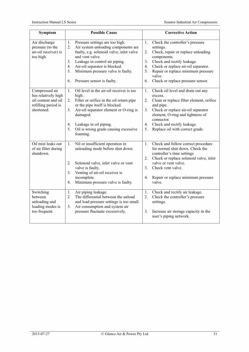
Air discharge pressure (to the air-oil receiver) is too high.
1. Pressure settings are too high. 2. Air system unloading components are
faulty, e.g. solenoid valve, inlet valve and vent valve.
3. Leakage in control air piping. 4. Air-oil separator is blocked. 5. Minimum pressure valve is faulty. 6. Pressure sensor is faulty.
1. Check the controller’s pressure settings.
2. Check, repair or replace unloading components.
3. Check and rectify leakage. 4. Check or replace air-oil separator. 5. Repair or replace minimum pressure
valve. 6. Check or replace pressure sensor.
Compressed air has relatively high oil content and oil refilling period is shortened.
1. Oil level in the air-oil receiver is too high.
2. Filter or orifice in the oil return pipe or the pipe itself is blocked.
3. Air-oil separator element or O-ring is damaged.
4. Leakage in oil piping. 5. Oil is wrong grade causing excessive
foaming.
1. Check oil level and drain out any excess.
2. Clean or replace filter element, orifice and pipe.
3. Check or replace air-oil separator element, O-ring and tightness of connector.
4. Check and rectify leakage. 5. Replace oil with correct grade.
Oil mist leaks out of air filter during shutdown.
1. Nil or insufficient operation in unloading mode before shut down.
2. Solenoid valve, inlet valve or vent
valve is faulty. 3. Venting of air-oil receiver is
incomplete. 4. Minimum pressure valve is faulty.
1. Check and follow correct procedure for normal shut down. Check the controller’s time settings
2. Check or replace solenoid valve, inlet valve or vent valve.
3. Check vent valve. 4. Repair or replace minimum pressure
valve.
Switching between unloading and loading modes is too frequent.
1. Air piping leakage. 2. The differential between the unload
and load pressure settings is too small. 3. Air consumption and system air
pressure fluctuate excessively.
1. Check and rectify air leakage. 2. Check the controller’s pressure
settings. 3. Increase air storage capacity in the
user’s piping network.
Instruction Manual LS Series Senator Industrial Air Compressors
2015-07-27 © Glenco Air & Power Pty Ltd 32
8.0 Warranty 8.1 Proof of Purchase Please complete the following details about your air compressor for future reference regarding warranty, spare parts and service. Date Purchase: …………….......................................................................................................... Purchased From: ……………………………………………………………………………….. Tax Invoice Number: …………………………………………………………………………… Air Compressor Model Number: ................................................................................................. Air Compressor Serial Number: ……………………………………………………………….. It is recommended that you keep a copy of the original tax invoice with this manual. 8.2 Warrantor Name: Glenco Air & Power Pty Ltd
(ABN 21101370085) Address: 21 Resource Street, Parkinson, QLD, 4115, Australia Phone: (07) 3386 9999 Fax: (07) 3386 9988 Email: [email protected] Web: www.glencoairpower.com.au 8.3 Warranty Conditions Glenco Air & Power Pty Ltd (the “Company”) warrants that the Goods shall be free from defects in material and workmanship for a period of twelve (12) months from the date of original sale (hereinafter the “Warranty Period”). The Warranty Period is continuous from the date of original sale and does not restart upon the repair or replacement of the Goods or any part thereof. Upon return – transportation charges prepaid by the Consumer – to the Company’s or its nominated dealer’s premises within the Warranty Period, the Company shall repair or replace, at its option, any Goods which it determines to contain defective material or workmanship, and shall return said Goods to the Consumer free-on-board (FOB) at the Company’s or
Instruction Manual LS Series Senator Industrial Air Compressors
2015-07-27 © Glenco Air & Power Pty Ltd 33
agent’s premises. The repair or replacement work will be scheduled and performed according to the Company’s normal work flow and availability of replacement parts. The Company shall not be obligated, however, to repair or replace Goods which have been: repaired by others; abused; improperly installed, operated, maintained, repaired, transported or stored; not serviced to schedule using genuine spare parts; altered or otherwise misused or damaged in any way. The Company shall not be responsible for any diagnosis, communication, dismantling, packing, handling, freight, and reassembly or reinstallation charges. Freight damage, pre-delivery service, normal operating adjustments, preventative maintenance service, consumable items, cosmetic damage, corrosion, erosion, normal wear and tear, performance, merchantability, and fitness for a particular purpose are not covered under this Warranty. Consumable items include lubricants, filters and V-belts. The Company shall not be liable for any repairs, replacements, or adjustments to the Goods or any costs of labour performed by the Consumer or others without the Company’s prior written approval. To the extent permissible by law and notwithstanding any other clause in these Warranty Conditions, the Company excludes all liability whatsoever to the Consumer arising out of or in any way connected with a contract for any consequential or indirect losses of any kind howsoever arising and whether caused by breach of statute, breach of contract, negligence or other tort. The Company’s liability will be limited to, in the case of products, the replacement of the products, the supply of equivalent products or the payment of the cost of replacing the products or of acquiring equivalent products or, in the case of services, the supply of the services again or the payment of the cost of having the services supplied again. The choice of remedy will be at the discretion of the Company and the Consumer acknowledges that this limitation of liability is fair and reasonable. This Warranty is available only to the original Consumer bearing the original tax invoice from the Company or one of its authorized dealers as proof of purchase. Goods purchased from any other party such as a private seller, auction house, eBay seller, etc. are not covered by this Warranty. Our goods come with guarantees that cannot be excluded under the Australian Consumer Law. You are entitled to a replacement or refund for a major failure and compensation for any other reasonably foreseeable loss or damage. You are also entitled to have the goods repaired or replaced if the goods fail to be of acceptable quality and the failure does not amount to a major failure.
Instruction Manual LS Series Senator Industrial Air Compressors
2015-07-27 © Glenco Air & Power Pty Ltd 34
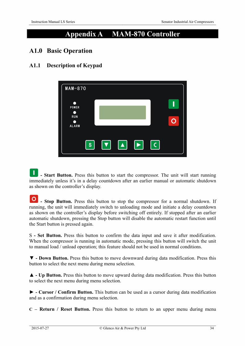
Appendix A MAM-870 Controller A1.0 Basic Operation A1.1 Description of Keypad
- Start Button. Press this button to start the compressor. The unit will start running immediately unless it’s in a delay countdown after an earlier manual or automatic shutdown as shown on the controller’s display.
- Stop Button. Press this button to stop the compressor for a normal shutdown. If running, the unit will immediately switch to unloading mode and initiate a delay countdown as shown on the controller’s display before switching off entirely. If stopped after an earlier automatic shutdown, pressing the Stop button will disable the automatic restart function until the Start button is pressed again. S - Set Button. Press this button to confirm the data input and save it after modification. When the compressor is running in automatic mode, pressing this button will switch the unit to manual load / unload operation; this feature should not be used in normal conditions. - Down Button. Press this button to move downward during data modification. Press this button to select the next menu during menu selection. - Up Button. Press this button to move upward during data modification. Press this button to select the next menu during menu selection. - Cursor / Confirm Button. This button can be used as a cursor during data modification and as a confirmation during menu selection. C – Return / Reset Button. Press this button to return to an upper menu during menu

Instruction Manual LS Series Senator Industrial Air Compressors
2015-07-27 © Glenco Air & Power Pty Ltd 35
selection. Press and hold this button for 5 seconds to reset the compressor when the unit is stopped after alarm shutdown. POWER Indicator. The red light is illuminated continuously whenever the compressor’s electrical power supply is switched on. RUN Indicator. The green light is illuminated continuously whenever the compressor is running. ALARM Indicator: The red light flashes accompanied by a continuous audible beep whenever the controller detects a warning or pre-alarm condition, e.g. oil filter overdue for replacement. The red light is illuminated continuously accompanied by a continuous audible beep whenever the controller detects an alarm condition and prevents the compressor from starting or shuts it down if already running, e.g. electrical supply phase reversal, high temperature, etc. A1.2 Status Display and Operation The display interface appears as follows when the compressor is first switched on: The status display will change after 5 seconds to the following standard layout: Press the button to display the following: During normal compressor operation, pressing the button will cycle the top line of the display between the outlet air pressure and the air end discharge temperature readings as shown above. Concurrently during normal compressor operation, the bottom line of the display will indicate the status of the unit as described in the following table.
PRES: 0.00MPa SYS STOP
TEMP: 20 SYS STOP
SCREW COMPRESSOR
Instruction Manual LS Series Senator Industrial Air Compressors
2015-07-27 © Glenco Air & Power Pty Ltd 36
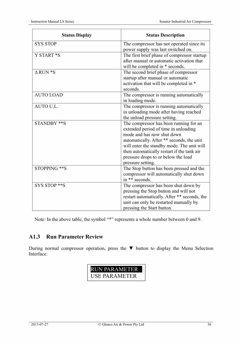
Status Display Status Description
SYS STOP The compressor has not operated since its power supply was last switched on.
Y START *S The first brief phase of compressor startup after manual or automatic activation that will be completed in * seconds.
Δ RUN *S The second brief phase of compressor startup after manual or automatic activation that will be completed in * seconds.
AUTO LOAD The compressor is running automatically in loading mode.
AUTO U.L. The compressor is running automatically in unloading mode after having reached the unload pressure setting.
STANDBY **S The compressor has been running for an extended period of time in unloading mode and has now shut down automatically. After ** seconds, the unit will enter the standby mode. The unit will then automatically restart if the tank air pressure drops to or below the load pressure setting.
STOPPING **S The Stop button has been pressed and the compressor will automatically shut down in ** seconds.
SYS STOP **S The compressor has been shut down by pressing the Stop button and will not restart automatically. After ** seconds, the unit can only be restarted manually by pressing the Start button.
Note: In the above table, the symbol “*” represents a whole number between 0 and 9.
A1.3 Run Parameter Review During normal compressor operation, press the button to display the Menu Selection Interface:
RUN PARAMETER USE PARAMETER

Instruction Manual LS Series Senator Industrial Air Compressors
2015-07-27 © Glenco Air & Power Pty Ltd 37
With the black cursor on the RUN PARAMETER selection, press the button to display the first run parameter screen: Then press the button repeatedly to scroll through the full list of run parameters and their status as described in the table below.
Run Parameter Display Run Parameter Description
MOTOR (A) Main motor current in each of the three phases.
FAN (A) Fan motor current in each of the three phases.
TOTAL RUN TIME The total accumulated running time of the compressor.
TOTAL LOAD TIME The total time that the compressor has been running in loading mode.
LOAD NUMBER The total number of times that the compressor has run in loading mode.
THIS RUN TIME The total time that the compressor has been running since last being manually started by pushing the Start button.
THIS LOAD TIME The total time that the compressor has been running in loading mode since last being manually started by pushing the Start button.
OIL FILTER TIME The total time that the compressor has been running since its last oil filter replacement.
O-A FILTER TIME The total time that the compressor has been running since its last air-oil separator replacement.
AIR FILTER TIME The total time that the compressor has been running since its last air filter replacement.
LUBE TIME The total time that the compressor has been running since its last oil change.
GREASE TIME The total time that the compressor has been running since its motor bearings have been re-greased. Note: This function is not relevant as the motor bearings are pre-greased and sealed for life.
BELT TIME The total time that the compressor has been running since its V-belts have been replaced.
MOTOR(A) A- 0.0 B- 0.0 C- 0.0
Instruction Manual LS Series Senator Industrial Air Compressors
2015-07-27 © Glenco Air & Power Pty Ltd 38
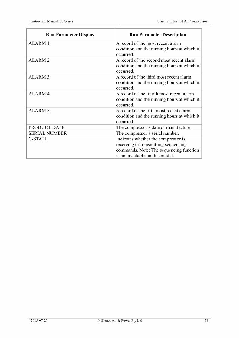
Run Parameter Display Run Parameter Description
ALARM 1 A record of the most recent alarm condition and the running hours at which it occurred.
ALARM 2 A record of the second most recent alarm condition and the running hours at which it occurred.
ALARM 3 A record of the third most recent alarm condition and the running hours at which it occurred.
ALARM 4 A record of the fourth most recent alarm condition and the running hours at which it occurred.
ALARM 5 A record of the fifth most recent alarm condition and the running hours at which it occurred.
PRODUCT DATE The compressor’s date of manufacture. SERIAL NUMBER The compressor’s serial number. C-STATE Indicates whether the compressor is
receiving or transmitting sequencing commands. Note: The sequencing function is not available on this model.
Instruction Manual LS Series Senator Industrial Air Compressors
2015-07-27 © Glenco Air & Power Pty Ltd 39
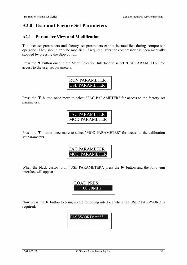
A2.0 User and Factory Set Parameters A2.1 Parameter View and Modification The user set parameters and factory set parameters cannot be modified during compressor operation. They should only be modified, if required, after the compressor has been manually stopped by pressing the Stop button. Press the button once in the Menu Selection Interface to select "USE PARAMETER" for access to the user set parameters. Press the button once more to select "FAC PARAMETER" for access to the factory set parameters. Press the button once more to select "MOD PARAMETER" for access to the calibration set parameters. When the black cursor is on "USE PARAMETER", press the button and the following interface will appear: Now press the button to bring up the following interface where the USER PASSWORD is required:
LOAD PRES: 00.70MPa
PASSWORD: ****
RUN PARAMETER USE PARAMETER
FAC PARAMETER MOD PARAMETER
FAC PARAMETER MOD PARAMETER
Instruction Manual LS Series Senator Industrial Air Compressors
2015-07-27 © Glenco Air & Power Pty Ltd 40
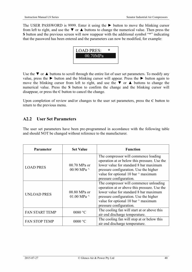
The USER PASSWORD is 9999. Enter it using the button to move the blinking cursor from left to right, and use the or buttons to change the numerical value. Then press the S button and the previous screen will now reappear with the additional symbol “*” indicating that the password has been entered and the parameters can now be modified, for example: Use the or buttons to scroll through the entire list of user set parameters. To modify any value, press the button and the blinking cursor will appear. Press the button again to move the blinking cursor from left to right, and use the or buttons to change the numerical value. Press the S button to confirm the change and the blinking cursor will disappear, or press the C button to cancel the change. Upon completion of review and/or changes to the user set parameters, press the C button to return to the previous menu. A2.2 User Set Parameters The user set parameters have been pre-programmed in accordance with the following table and should NOT be changed without reference to the manufacturer.
Parameter Set Value Function
LOAD PRES 00.70 MPa or 00.90 MPa ^
The compressor will commence loading operation at or below this pressure. Use the lower value for standard 8 bar maximum pressure configuration. Use the higher value for optional 10 bar ^ maximum pressure configuration.
UNLOAD PRES 00.80 MPa or 01.00 MPa ^
The compressor will commence unloading operation at or above this pressure. Use the lower value for standard 8 bar maximum pressure configuration. Use the higher value for optional 10 bar ^ maximum pressure configuration.
FAN START TEMP 0080 °C The cooling fan will start at or above this air end discharge temperature.
FAN STOP TEMP 0000 °C The cooling fan will stop at or below this air end discharge temperature.
LOAD PRES: *
00.70MPa
Instruction Manual LS Series Senator Industrial Air Compressors
2015-07-27 © Glenco Air & Power Pty Ltd 41
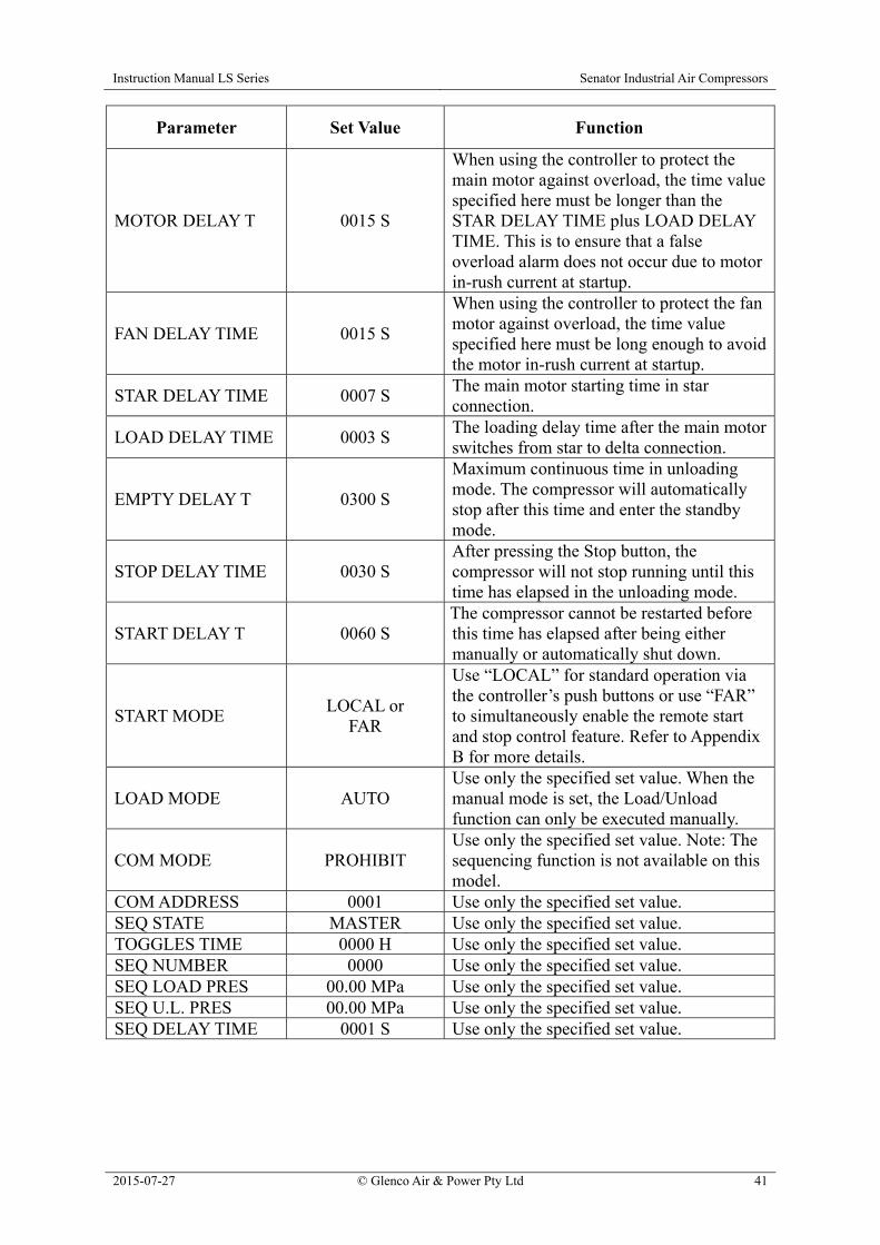
Parameter Set Value Function
MOTOR DELAY T 0015 S
When using the controller to protect the main motor against overload, the time value specified here must be longer than the STAR DELAY TIME plus LOAD DELAY TIME. This is to ensure that a false overload alarm does not occur due to motor in-rush current at startup.
FAN DELAY TIME 0015 S
When using the controller to protect the fan motor against overload, the time value specified here must be long enough to avoid the motor in-rush current at startup.
STAR DELAY TIME 0007 S The main motor starting time in star connection.
LOAD DELAY TIME 0003 S The loading delay time after the main motor switches from star to delta connection.
EMPTY DELAY T 0300 S
Maximum continuous time in unloading mode. The compressor will automatically stop after this time and enter the standby mode.
STOP DELAY TIME 0030 S After pressing the Stop button, the compressor will not stop running until this time has elapsed in the unloading mode.
START DELAY T 0060 S The compressor cannot be restarted before this time has elapsed after being either manually or automatically shut down.
START MODE LOCAL or
FAR
Use “LOCAL” for standard operation via the controller’s push buttons or use “FAR” to simultaneously enable the remote start and stop control feature. Refer to Appendix B for more details.
LOAD MODE AUTO Use only the specified set value. When the manual mode is set, the Load/Unload function can only be executed manually.
COM MODE PROHIBIT Use only the specified set value. Note: The sequencing function is not available on this model.
COM ADDRESS 0001 Use only the specified set value. SEQ STATE MASTER Use only the specified set value. TOGGLES TIME 0000 H Use only the specified set value. SEQ NUMBER 0000 Use only the specified set value. SEQ LOAD PRES 00.00 MPa Use only the specified set value. SEQ U.L. PRES 00.00 MPa Use only the specified set value. SEQ DELAY TIME 0001 S Use only the specified set value.

Instruction Manual LS Series Senator Industrial Air Compressors
2015-07-27 © Glenco Air & Power Pty Ltd 42
Parameter Set Value Function
OIL FILTER RST 0000 H Reset to zero hours ONLY when the oil filter is replaced.
O-A FILTER RST 0000 H Reset to zero hours ONLY when the air-oil separator is replaced.
AIR FILTER RST 0000 H Reset to zero hours ONLY when the air filter is replaced.
LUBE RESET 0000 H Reset to zero hours ONLY when the lubricating oil is changed.
GREASE RESET 0000 H Reset to zero hours ONLY when the motor is re-greased.
BELT RESET 0000 H Reset to zero hours ONLY when the V-belts are replaced.
OIL FILTER SET 1000 H Oil filter replacement interval. O-A FILTER SET 2000 H Air-oil separator replacement interval. AIR FILTER SET 2000 H Air filter replacement interval. LUBE SET 2000 H Lubricating oil change interval. GREASE SET 2000 H Motor re-grease interval. BELT SET 8000 H V-belt replacement interval.
LANGUAGE SEL. ENGLISH Set this value to the required display language.
USER PASSWORD 9999 For access to the User Set Parameters.
^ DO NOT enter the 10 bar maximum pressure parameters without also changing the compressor’s air end speed by replacing certain V-belt drive components otherwise the unit will be damaged. Refer to the manufacturer for instructions.
A2.3 Factory Set Parameters The factory set parameters can only be accessed for review and/or change by using the FACTORY SET PASSWORD, which is made available to service technicians upon request. It is unlikely that any of the factory set parameters would need to be changed during the life of the air compressor set after dispatch from the manufacturer. The factory set parameters have been pre-programmed in accordance with the table shown below. Note that certain parameters prefixed “#” can only be accessed with the SUPER PASSWORD, which is only available for use by the manufacturer.
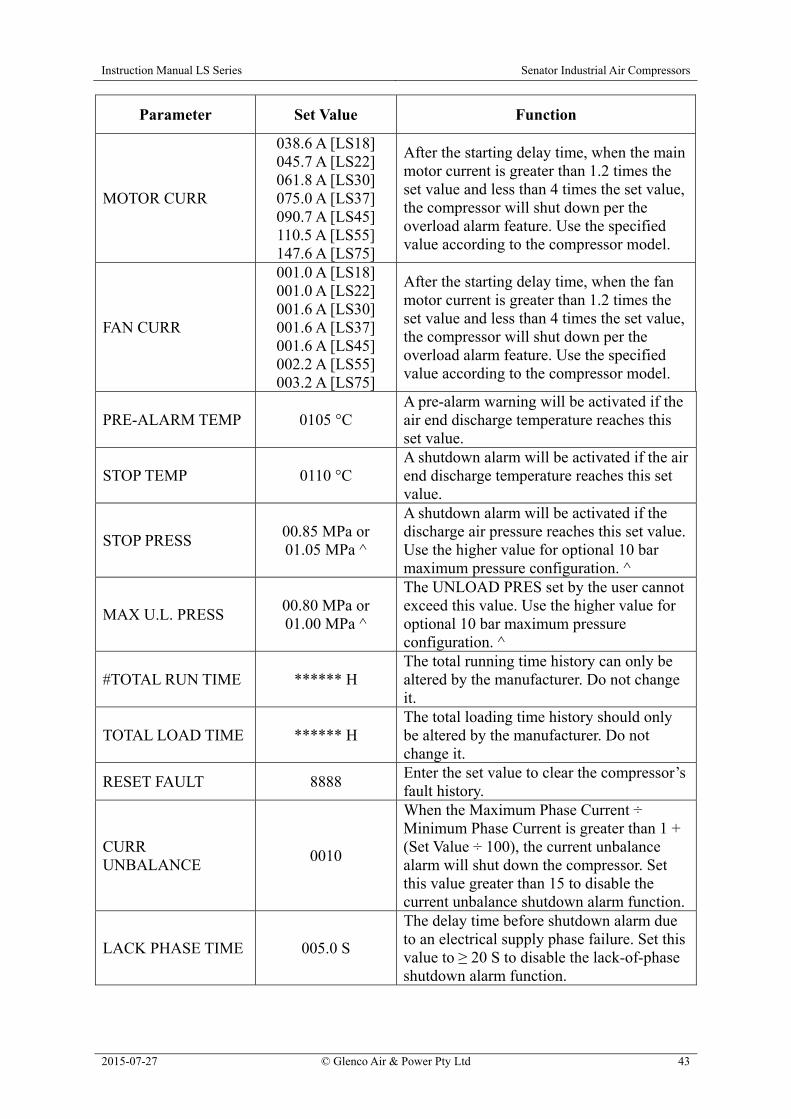
Instruction Manual LS Series Senator Industrial Air Compressors
2015-07-27 © Glenco Air & Power Pty Ltd 43
Parameter Set Value Function
MOTOR CURR
038.6 A [LS18] 045.7 A [LS22] 061.8 A [LS30] 075.0 A [LS37] 090.7 A [LS45] 110.5 A [LS55] 147.6 A [LS75]
After the starting delay time, when the main motor current is greater than 1.2 times the set value and less than 4 times the set value, the compressor will shut down per the overload alarm feature. Use the specified value according to the compressor model.
FAN CURR
001.0 A [LS18] 001.0 A [LS22] 001.6 A [LS30] 001.6 A [LS37] 001.6 A [LS45] 002.2 A [LS55] 003.2 A [LS75]
After the starting delay time, when the fan motor current is greater than 1.2 times the set value and less than 4 times the set value, the compressor will shut down per the overload alarm feature. Use the specified value according to the compressor model.
PRE-ALARM TEMP 0105 °C A pre-alarm warning will be activated if the air end discharge temperature reaches this set value.
STOP TEMP 0110 °C A shutdown alarm will be activated if the air end discharge temperature reaches this set value.
STOP PRESS 00.85 MPa or 01.05 MPa ^
A shutdown alarm will be activated if the discharge air pressure reaches this set value. Use the higher value for optional 10 bar maximum pressure configuration. ^
MAX U.L. PRESS 00.80 MPa or 01.00 MPa ^
The UNLOAD PRES set by the user cannot exceed this value. Use the higher value for optional 10 bar maximum pressure configuration. ^
#TOTAL RUN TIME ****** H The total running time history can only be altered by the manufacturer. Do not change it.
TOTAL LOAD TIME ****** H The total loading time history should only be altered by the manufacturer. Do not change it.
RESET FAULT 8888 Enter the set value to clear the compressor’s fault history.
CURR UNBALANCE
0010
When the Maximum Phase Current ÷ Minimum Phase Current is greater than 1 + (Set Value ÷ 100), the current unbalance alarm will shut down the compressor. Set this value greater than 15 to disable the current unbalance shutdown alarm function.
LACK PHASE TIME 005.0 S
The delay time before shutdown alarm due to an electrical supply phase failure. Set this value to ≥ 20 S to disable the lack-of-phase shutdown alarm function.
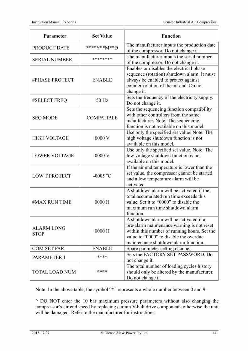
Instruction Manual LS Series Senator Industrial Air Compressors
2015-07-27 © Glenco Air & Power Pty Ltd 44
Parameter Set Value Function
PRODUCT DATE ****Y**M**D The manufacturer inputs the production date of the compressor. Do not change it.
SERIAL NUMBER ******** The manufacturer inputs the serial number of the compressor. Do not change it.
#PHASE PROTECT ENABLE
Enables or disables the electrical phase sequence (rotation) shutdown alarm. It must always be enabled to protect against counter-rotation of the air end. Do not change it.
#SELECT FREQ 50 Hz Sets the frequency of the electricity supply. Do not change it.
SEQ MODE COMPATIBLE
Sets the sequencing function compatibility with other controllers from the same manufacturer. Note: The sequencing function is not available on this model.
HIGH VOLTAGE 0000 V Use only the specified set value. Note: The high voltage shutdown function is not available on this model.
LOWER VOLTAGE 0000 V Use only the specified set value. Note: The low voltage shutdown function is not available on this model.
LOW T PROTECT -0005 °C
If the air end temperature is lower than the set value, the compressor cannot be started and a low temperature alarm will be activated.
#MAX RUN TIME 0000 H
A shutdown alarm will be activated if the total accumulated run time exceeds this value. Set it to “0000” to disable the maximum run time shutdown alarm function.
ALARM LONG STOP
0000 H
A shutdown alarm will be activated if a pre-alarm maintenance warning is not reset within this number of running hours. Set the value to “0000” to disable the overdue maintenance shutdown alarm function.
COM SET PAR. ENABLE Spare parameter setting channel.
PARAMETER 1 **** Sets the FACTORY SET PASSWORD. Do not change it.
TOTAL LOAD NUM **** The total number of loading cycles history should only be altered by the manufacturer. Do not change it.
Note: In the above table, the symbol “*” represents a whole number between 0 and 9.
^ DO NOT enter the 10 bar maximum pressure parameters without also changing the compressor’s air end speed by replacing certain V-belt drive components otherwise the unit will be damaged. Refer to the manufacturer for instructions.

Instruction Manual LS Series Senator Industrial Air Compressors
2015-07-27 © Glenco Air & Power Pty Ltd 45
A2.4 Calibration Set Parameters (MOD PARAMETER) The calibration set parameters can only be accessed for review and/or change by using the CALIBRATION SET PASSWORD, which is made available to service technicians upon request. It is unlikely that any of the calibration set parameters would need to be changed during the life of the air compressor set after dispatch from the manufacturer. The calibration set parameters have been pre-programmed in accordance with the table shown below.
Parameter Set Value Function
MOTOR A
TARGET 000.0 A
Enter the true current value (measured with an accurate external ammeter) in the main motor supply Phase A while the compressor is running in a steady state condition. The controller will divide the true current value by the indicated current value (as measured internally by the compressor) to work out the calibration coefficient. The true current value is entered here for one-time calculation only and will not be saved.
COEF. 1.000
The controller displays the corrected current value for main motor supply Phase A, which equals the indicated current value times the calibration coefficient.
MOTOR B TARGET 000.0 A [As described above.]
COEF. 1.000 [As described above.]
MOTOR C TARGET 000.0 A [As described above.]
COEF. 1.000 [As described above.]
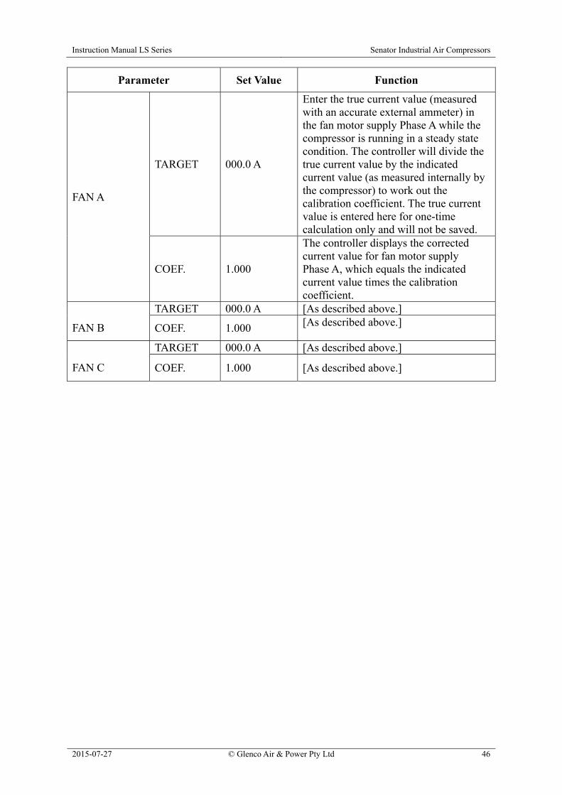
Instruction Manual LS Series Senator Industrial Air Compressors
2015-07-27 © Glenco Air & Power Pty Ltd 46
Parameter Set Value Function
FAN A
TARGET 000.0 A
Enter the true current value (measured with an accurate external ammeter) in the fan motor supply Phase A while the compressor is running in a steady state condition. The controller will divide the true current value by the indicated current value (as measured internally by the compressor) to work out the calibration coefficient. The true current value is entered here for one-time calculation only and will not be saved.
COEF. 1.000
The controller displays the corrected current value for fan motor supply Phase A, which equals the indicated current value times the calibration coefficient.
FAN B
TARGET 000.0 A [As described above.]
COEF. 1.000 [As described above.]
FAN C
TARGET 000.0 A [As described above.]
COEF. 1.000 [As described above.]

Instruction Manual LS Series Senator Industrial Air Compressors
2015-07-27 © Glenco Air & Power Pty Ltd 47
A3.0 Alarms and Messages A3.1 Pre-Alarm Warnings The controller will intermittently display a self-explanatory pre-alarm warning together with a continuous audible beep and flashing ALARM indicator light when certain parameter limits are exceeded. Two examples are shown below: Although the compressor will continue to operate whilst signalling a pre-alarm warning, the suspect condition should be promptly investigated and rectified to avoid the inconvenience of an alarm shutdown and possible damage to the unit. A3.2 Shutdown Fault Alarms In the event of a fault being detected in one or more of the monitored operating parameters, the compressor will shut down automatically. An audible alarm will beep continuously and the ALARM indicator light will be illuminated. The controller will indicate “STOP” and a fault message. For example: The following table provides a guide to interpreting the fault message and remedying the problem.
PRE-ALARM: 2010H OIL LIFE END
PRE-ALARM: TEMP HIGH 105°C
STOP: P HIGH 0.86MPa
STOP: T HIGH 110°C
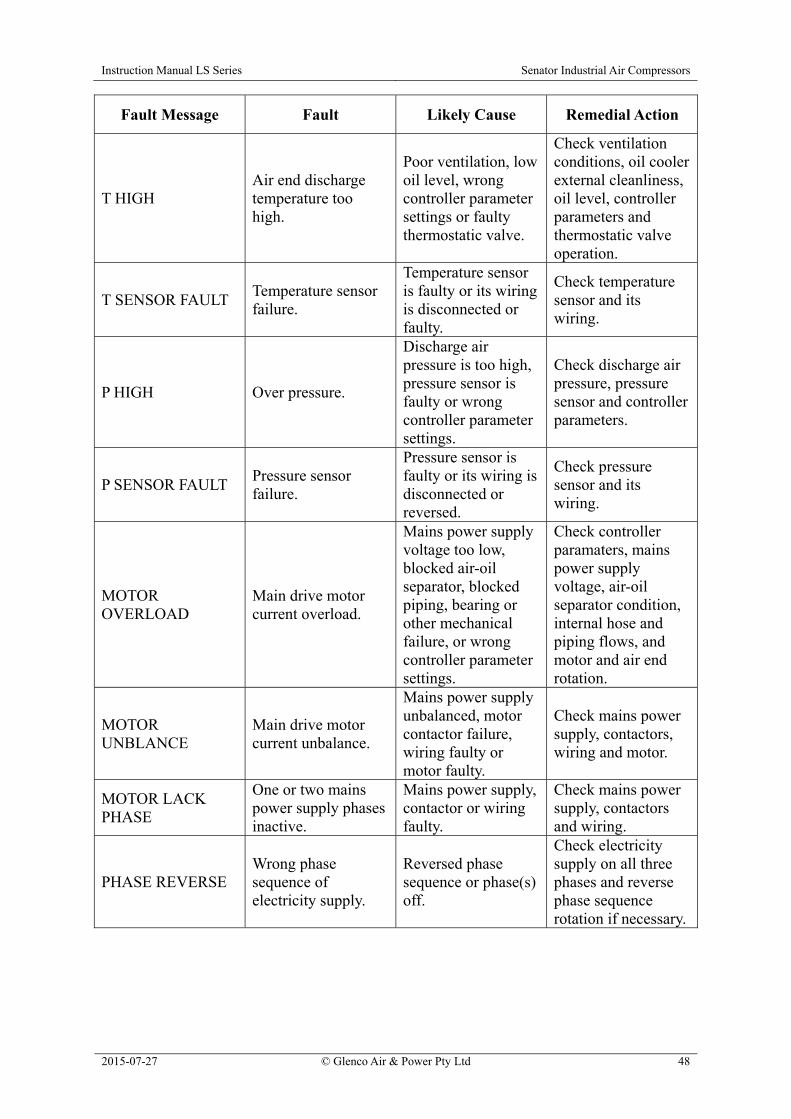
Instruction Manual LS Series Senator Industrial Air Compressors
2015-07-27 © Glenco Air & Power Pty Ltd 48
Fault Message Fault Likely Cause Remedial Action
T HIGH Air end discharge temperature too high.
Poor ventilation, low oil level, wrong controller parameter settings or faulty thermostatic valve.
Check ventilation conditions, oil cooler external cleanliness, oil level, controller parameters and thermostatic valve operation.
T SENSOR FAULT Temperature sensor failure.
Temperature sensor is faulty or its wiring is disconnected or faulty.
Check temperature sensor and its wiring.
P HIGH Over pressure.
Discharge air pressure is too high, pressure sensor is faulty or wrong controller parameter settings.
Check discharge air pressure, pressure sensor and controller parameters.
P SENSOR FAULT Pressure sensor failure.
Pressure sensor is faulty or its wiring is disconnected or reversed.
Check pressure sensor and its wiring.
MOTOR OVERLOAD
Main drive motor current overload.
Mains power supply voltage too low, blocked air-oil separator, blocked piping, bearing or other mechanical failure, or wrong controller parameter settings.
Check controller paramaters, mains power supply voltage, air-oil separator condition, internal hose and piping flows, and motor and air end rotation.
MOTOR UNBLANCE
Main drive motor current unbalance.
Mains power supply unbalanced, motor contactor failure, wiring faulty or motor faulty.
Check mains power supply, contactors, wiring and motor.
MOTOR LACK PHASE
One or two mains power supply phases inactive.
Mains power supply, contactor or wiring faulty.
Check mains power supply, contactors and wiring.
PHASE REVERSE Wrong phase sequence of electricity supply.
Reversed phase sequence or phase(s) off.
Check electricity supply on all three phases and reverse phase sequence rotation if necessary.

Instruction Manual LS Series Senator Industrial Air Compressors
2015-07-27 © Glenco Air & Power Pty Ltd 49
Fault Message Fault Likely Cause Remedial Action
FAN OVERLOAD Fan motor current overload.
Mains power supply voltage too low, airflow restriction, fan blade interference, fan motor faulty or wrong controller parameter settings.
Check controller parameters, mains power supply voltage, airflow path, fan blade clearance, and fan motor function.
USER MISTAKE MAX RUN TIME value reached.
Total accumulated run time has exceeded MAX RUN TIME setting.
Set MAX RUN TIME parameter at “0000” to disable this function.
ALARM TOO LONG
ALARM LONG STOP value reached.
Run time since pre-alarm maintenance warning has exceeded ALARM LONG STOP setting.
Carry out any required maintenance and then set ALARM LONG STOP parameter at “0000” to disable this function.
VOLTAGE HIGH Unsupported controller feature not deactivated.
Wrong controller parameter setting.
Set HIGH VOLTAGE parameter at “0000”.
VOLTAGE LOW Unsupported controller feature not deactivated.
Wrong controller parameter setting.
Set LOWER VOLTAGE parameter at “0000”.
TEMP LOW Air end (discharge) temperature too low.
Ambient temperature too low or wrong controller parameter settings.
Check ambient / ventilation conditions and controller parameters.
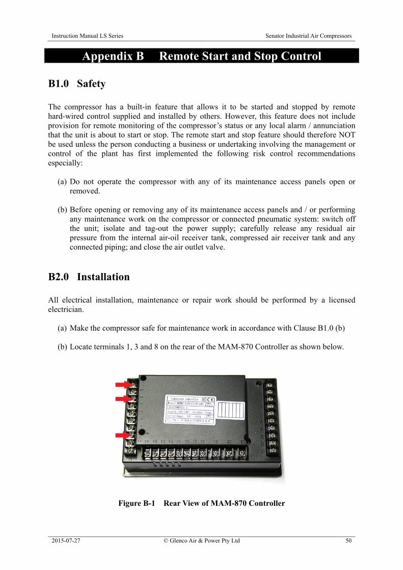
Instruction Manual LS Series Senator Industrial Air Compressors
2015-07-27 © Glenco Air & Power Pty Ltd 50
Appendix B Remote Start and Stop Control
B1.0 Safety The compressor has a built-in feature that allows it to be started and stopped by remote hard-wired control supplied and installed by others. However, this feature does not include provision for remote monitoring of the compressor’s status or any local alarm / annunciation that the unit is about to start or stop. The remote start and stop feature should therefore NOT be used unless the person conducting a business or undertaking involving the management or control of the plant has first implemented the following risk control recommendations especially:
(a) Do not operate the compressor with any of its maintenance access panels open or removed.
(b) Before opening or removing any of its maintenance access panels and / or performing
any maintenance work on the compressor or connected pneumatic system: switch off the unit; isolate and tag-out the power supply; carefully release any residual air pressure from the internal air-oil receiver tank, compressed air receiver tank and any connected piping; and close the air outlet valve.
B2.0 Installation All electrical installation, maintenance or repair work should be performed by a licensed electrician.
(a) Make the compressor safe for maintenance work in accordance with Clause B1.0 (b) (b) Locate terminals 1, 3 and 8 on the rear of the MAM-870 Controller as shown below.
Figure B-1 Rear View of MAM-870 Controller

Instruction Manual LS Series Senator Industrial Air Compressors
2015-07-27 © Glenco Air & Power Pty Ltd 51
(c) Connect a normally open, non-latching, single pole, push button switch (i.e. the remote control switch) between terminals 1 and 3 using a single twisted-pair, screened data or instrumentation cable. Connect one end only of the screen to earthing terminal 8. The circuit voltage and current are 25 V DC and 20 mA, respectively.
(d) Reinstall any components that were removed in Step (b) to give access to the rear of
the controller. (e) Prepare the compressor for use in accordance with Section 5.0. (f) Follow the procedure described in Section A2.0 to change the START MODE user set
parameter in the controller to the “FAR” set value. The compressor is now ready for operation by local command via the MAM-870 Controller or by remote control via the push button switch.
B3.0 Operation Pressing and holding the remote control switch for two seconds has the same functionality as pressing either the controller’s Start button (if the unit is shut down) or Stop button (if the unit is running). The remote control switch must be released (i.e. opened) and then pushed (i.e. closed) again for two seconds in order to cycle the unit to the next start or stop command. The functionality of the push buttons on the MAM-870 Controller remains unchanged when the remote control feature is enabled.

Instruction Manual LS Series Senator Industrial Air Compressors
2015-07-27 © Glenco Air & Power Pty Ltd 52
Maintenance and Repair Log
Date Maintenance or Repair Activity