Seminar Textbook - Chapter6: Alarm Screen
32
Otasuke GP-EX! 6- 0 Chapter 6 Alarm History Screen Alarm History Screen Chapter 6 Alarm History Screen ………………………………… 6-1 Display Alarm History in List ………………………… 6-2 Let’s Display Alarm History …………………………. 6-3 Read Data when Alarms Occur …………………… 6-12 Let’s Read Data when Alarm Occur ………………. 6-13 Let’s Edit Alarm Message ……………………………. 6-15 Alarm History Switch …………………………………. 6-17 Display Details/Countermeasures of Each Alarm … 6-18 Let’s Display Details of Each Alarm Message ……. 6-20 Save SRAM Data in CF Card……………………… 6-22 Display Banner Message …………………………… 6-27 Let’s Display Banner Messages …………………….. 6-28
Transcript of Seminar Textbook - Chapter6: Alarm Screen
Otasuke GP-EX!
6- 0
Chapter 6 Alarm History Screen
Alarm History Screen
Chapter 6
Alarm History Screen ………………………………… 6-1
Display Alarm History in List ………………………… 6-2
Let’s Display Alarm History …………………………. 6-3
Read Data when Alarms Occur …………………… 6-12
Let’s Read Data when Alarm Occur ………………. 6-13
Let’s Edit Alarm Message ……………………………. 6-15
Alarm History Switch …………………………………. 6-17
Display Details/Countermeasures of Each Alarm … 6-18
Let’s Display Details of Each Alarm Message ……. 6-20
Save SRAM Data in CF Card……………………… 6-22
Display Banner Message …………………………… 6-27
Let’s Display Banner Messages …………………….. 6-28
Otasuke GP-EX!
6- 1
Chapter 6 Alarm History Screen
Alarm History Screen
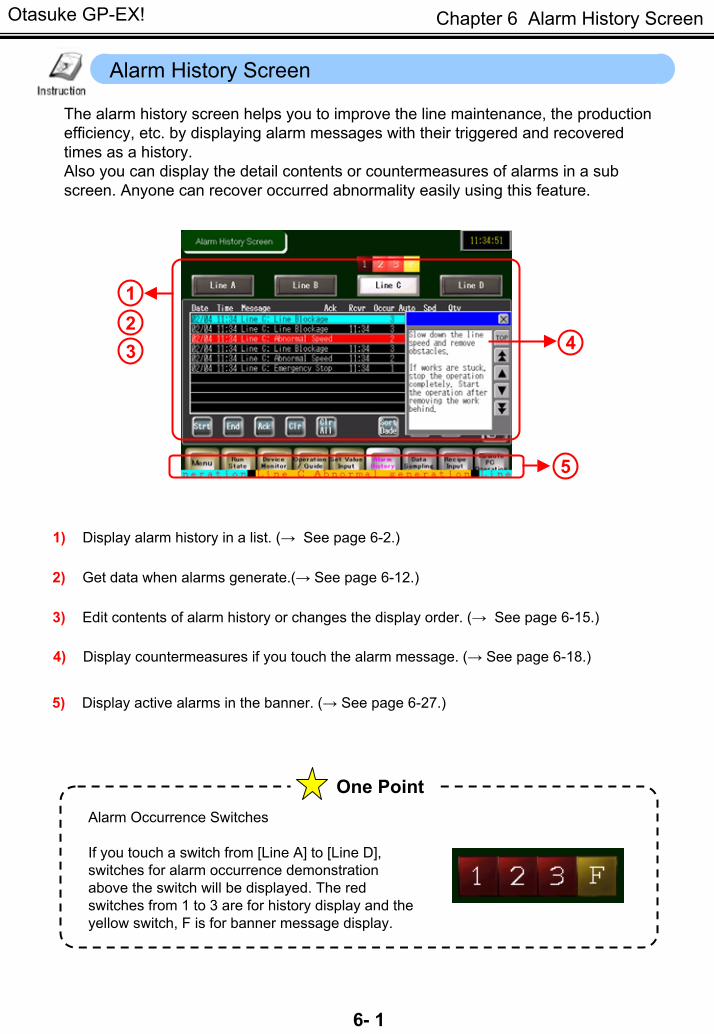
The alarm history screen helps you to improve the line maintenance, the production efficiency, etc. by displaying alarm messages with their triggered and recovered times as a history. Also you can display the detail contents or countermeasures of alarms in a sub screen. Anyone can recover occurred abnormality easily using this feature.
123 4
5
1) Display alarm history in a list. (→ See page 6-2.)
2) Get data when alarms generate.(→ See page 6-12.)
3) Edit contents of alarm history or changes the display order. (→ See page 6-15.)
4) Display countermeasures if you touch the alarm message. (→ See page 6-18.)
5) Display active alarms in the banner. (→ See page 6-27.)
One Point Alarm Occurrence Switches
If you touch a switch from [Line A] to [Line D], switches for alarm occurrence demonstration above the switch will be displayed. The red switches from 1 to 3 are for history display and the yellow switch, F is for banner message display.
Otasuke GP-EX!
6- 2
Chapter 6 Alarm History Screen
Display Alarm History in List
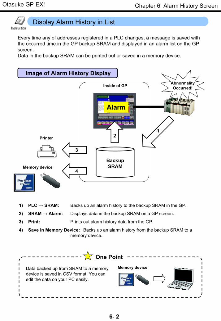
Every time any of addresses registered in a PLC changes, a message is saved with the occurred time in the GP backup SRAM and displayed in an alarm list on the GP screen. Data in the backup SRAM can be printed out or saved in a memory device.
Alarm
Image of Alarm History Display
BackupSRAM
1
3
4
Inside of GP
1) PLC → SRAM: Backs up an alarm history to the backup SRAM in the GP.
2) SRAM → Alarm: Displays data in the backup SRAM on a GP screen.
3) Print: Prints out alarm history data from the GP.
4) Save in Memory Device: Backs up an alarm history from the backup SRAM to a memory device.
Printer②2
AbnormalityOccurred!
Memory device
One Point
Data backed up from SRAM to a memory device is saved in CSV format. You can edit the data on your PC easily.
Memory device
Otasuke GP-EX!
6- 3
Chapter 6 Alarm History Screen
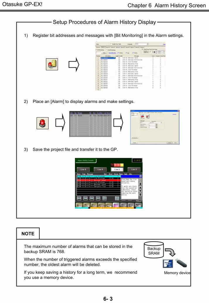
1) Register bit addresses and messages with [Bit Monitoring] in the Alarm settings.
2) Place an [Alarm] to display alarms and make settings.
3) Save the project file and transfer it to the GP.
Setup Procedures of Alarm History Display
The maximum number of alarms that can be stored in the backup SRAM is 768.
When the number of triggered alarms exceeds the specified number, the oldest alarm will be deleted.
If you keep saving a history for a long term, we recommend you use a memory device.
Memory device
BackupSRAM
NOTE
Otasuke GP-EX!
6- 4
Chapter 6 Alarm History Screen
Let’s Display Alarm History
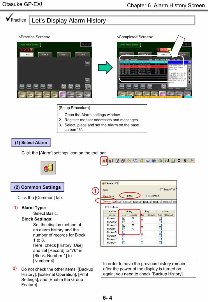
<Practice Screen> <Completed Screen>
(1) Select Alarm
Click the [Alarm] settings icon on the tool bar.
[Setup Procedure]
1. Open the Alarm settings window. 2. Register monitor addresses and messages. 3. Select, place and set the Alarm on the base
screen “6”.
(2) Common Settings
Alarm Type:Select Basic.
Block Settings:Set the display method of an alarm history and the number of records for Block 1 to 8. Here, check [History: Use] and set [Record] to “76” in [Block: Number 1] to [Number 4] .
1)
2)
Click the [Common] tab. 1
In order to have the previous history remain after the power of the display is turned on again, you need to check [Backup History].
Do not check the other items, [Backup History], [External Operation], [Print Settings], and [Enable the Group Feature].
Otasuke GP-EX!
6- 5
Chapter 6 Alarm History Screen
One Point
Block 3
Block 2
Block 1
BackupSRAM Line A ab Speed
Line A ab Elec.Line A Emergency
Base screen 1 Base screen 2 Base screen 3
Line B ab SpeedLine B ab Elec.
Line B EmergencyLine C ab SpeedLine C ab Elec.
Line C Emergency
Line A ab SpeedLine A ab Elec.
Line A Emergency
Block 1
Line B ab SpeedLine B ab Elec.
Line B Emergency
Line C ab SpeedLine C ab Elec.
Line C EmergencyBlock 2 Block 3
Base screen 1
Line A ab SpeedLine A ab Elec.
Line A Emergency
Block 1
Line B ab SpeedLine B ab Elec.
Line B Emergency
Line C ab SpeedLine C ab Elec.
Line C Emergency
Block 2 Block 3
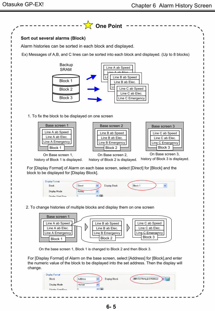
Sort out several alarms (Block)
Alarm histories can be sorted in each block and displayed.
Ex) Messages of A,B, and C lines can be sorted into each block and displayed. (Up to 8 blocks)
1. To fix the block to be displayed on one screen
On Base screen 1,history of Block 1 is displayed.
On Base screen 2, history of Block 2 is displayed.
On Base screen 3,history of Block 3 is displayed.
For [Display Format] of Alarm on each base screen, select [Direct] for [Block] and the block to be displayed for [Display Block].
2. To change histories of multiple blocks and display them on one screen
On the base screen 1, Block 1 is changed to Block 2 and then Block 3.
For [Display Format] of Alarm on the base screen, select [Address] for [Block],and enter the numeric value of the block to be displayed into the set address. Then the display will change.
Otasuke GP-EX!
6- 6
Chapter 6 Alarm History Screen
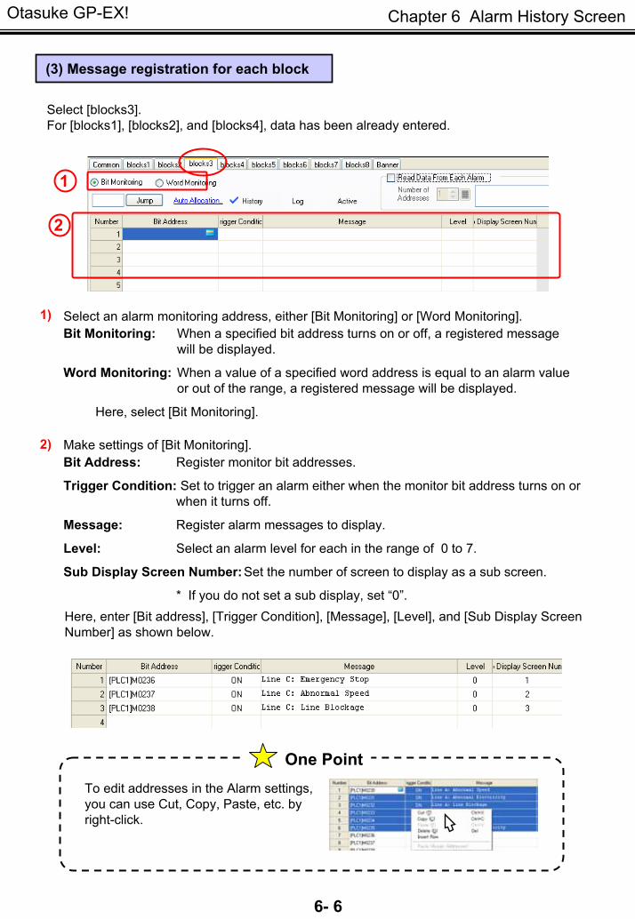
(3) Message registration for each block
Select [blocks3].For [blocks1], [blocks2], and [blocks4], data has been already entered.
1
2
1) Select an alarm monitoring address, either [Bit Monitoring] or [Word Monitoring]. Bit Monitoring: When a specified bit address turns on or off, a registered message
will be displayed.
Word Monitoring: When a value of a specified word address is equal to an alarm value or out of the range, a registered message will be displayed.
Here, select [Bit Monitoring].
2) Make settings of [Bit Monitoring]. Bit Address: Register monitor bit addresses.
Trigger Condition: Set to trigger an alarm either when the monitor bit address turns on or when it turns off.
Message: Register alarm messages to display.
Level: Select an alarm level for each in the range of 0 to 7.
Sub Display Screen Number:Set the number of screen to display as a sub screen.
* If you do not set a sub display, set “0”.Here, enter [Bit address], [Trigger Condition], [Message], [Level], and [Sub Display Screen Number] as shown below.
To edit addresses in the Alarm settings, you can use Cut, Copy, Paste, etc. by right-click.
One Point

Otasuke GP-EX!
6- 7
Chapter 6 Alarm History Screen
(4) Select/Place Alarm
Click the [Alarm] icon on the tool bar. 1) 1
2) Drag the range to place the alarm.
2
(5) Basic Settings
Double-click the placed alarm. 1)
Select [Show History]. 2)
2
3
Make settings as below. Display Block: Block 1Display Mode: HistoryDisplay Start Row: 1Display Rows: 10Display Row Spacing: 3
3)

Otasuke GP-EX!
6- 8
Chapter 6 Alarm History Screen
Log: An alarm is displayed by the triggered time, acknowledged time, and recovered time separately in different rows. It is useful in cases that the triggered and recovered times are on different dates.
History: A newly triggered alarm is displayed in a new row. The time when the alarm is acknowledged or recovered is added onto the same row.
Active: Only active alarms are displayed.The recovered alarm is cleared and no history remains.
One Point
* When you use multiple blocks, you can use different display modes by blocks.For example, you can use the “Active” mode which does not leave histories for a line with low level of importance, the “Log” mode to leave histories for a line with high level of importance, etc.
Example of Display Mode (Active/History/Log)
e.g.)
e.g.)
e.g.)

Otasuke GP-EX!
6- 9
Chapter 6 Alarm History Screen
(6) Item Settings
Here on this tab, you can make each setting such asshowing/Hiding items, Show Item Names,and Display Order.
Check from [Date] up to [Occurrences]. Set [Display Characters] as below.
Left Margin: 0Date: 6Trigger: 6Message: 20Acknowledged: 6Recovery: 6Occurrences: 5
Check all of [Show Item Names] and register item names to display as above.
1
1) Click and open the [Extended] settings.
2)
2
3
4
3) In [Format], set [Date] to “mm/dd” and [Time] to “24:00”.
In [Show-Item-Name Settings], select [Direct Text] and make settings as below.
Font Type: Standard Font Size: 8 x 16 PixelsDisplay Language:ASCII Text Attribute: Normal Display Color: 7 Blink: NoneBackground Color:Transparent
4)
(7) Color Settings
Set [Display Color], [Background Color], and [Blink] as you like.
Set [Clear Color] as you like.
Otasuke GP-EX!
6- 10
Chapter 6 Alarm History Screen
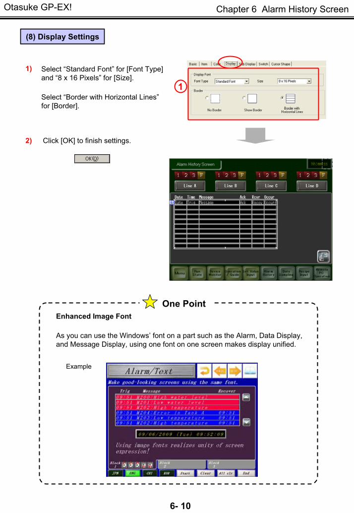
(8) Display Settings
1) Select “Standard Font” for [Font Type] and “8 x 16 Pixels” for [Size].
Select “Border with Horizontal Lines”for [Border].
1
2) Click [OK] to finish settings.
Enhanced Image Font
As you can use the Windows’ font on a part such as the Alarm, Data Display, and Message Display, using one font on one screen makes display unified.
Example
One Point

Otasuke GP-EX!
6- 11
Chapter 6 Alarm History Screen
One Point
Useful features of Alarm History Settings (Alarm Expansion Function)
1. The number of each block’s alarm messages to register can be expanded to up to 32,767. It’s useful for controlling lots of alarms in such a case as communicating with multiple
devices/PLCs.
Up to 32,767 for 1 block.
2. Multiple addresses (up to 256 units) can be allocated to one message and it’s not necessary to repeatedly register similar messages. That can reduce work processes of drawing.
Example: Registration of alarm settings
Example: Display of the display’s screen
On the screen of the display, the registered unit name and messages are displayed in the Message column.
NOTE
To use Alarm Expansion FunctionTo use the 2 functions described above, it’s necessary to attach a function-expanding memory, GP3000-EXDM01(separately sold) to the main unit. Select [Extended] for [Alarm Type] of Alarm Settings and change the system settings, and the aforementioned settings will be possible.
For details, refer to the Reference Manual.19.10.1 Common (Alarm) Settings Guide
7.5“ or larger GP3000 series support it.The way to install the function-expanding memory differs depending on a model. (The picture shows GP3600T)
Otasuke GP-EX!
6- 12
Chapter 6 Alarm History Screen
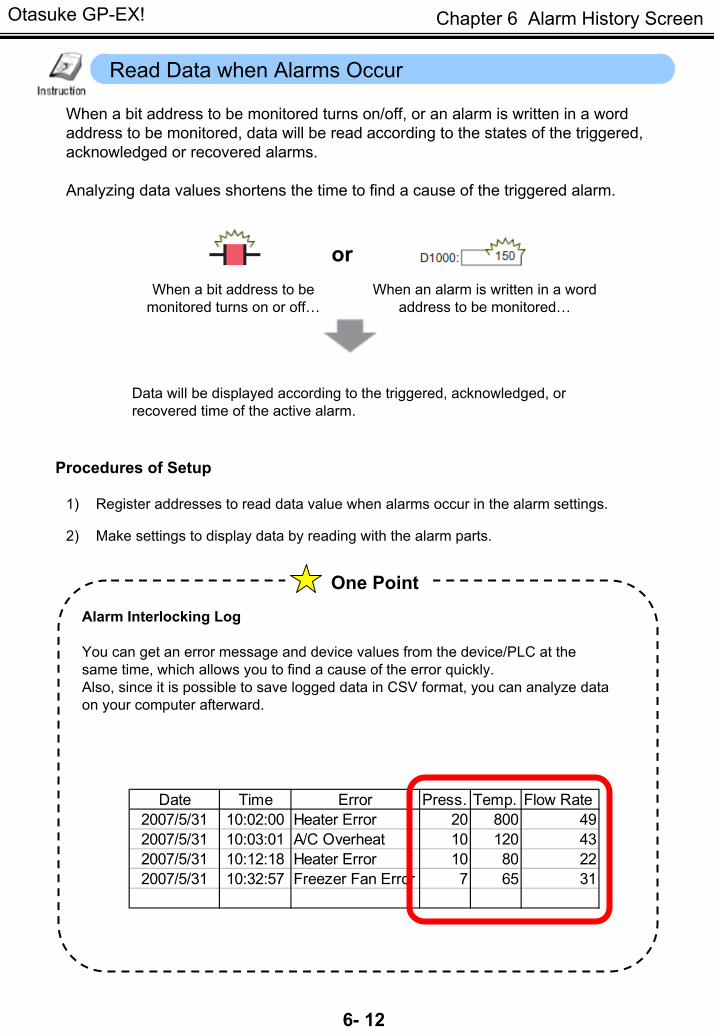
When a bit address to be monitored turns on/off, or an alarm is written in a word address to be monitored, data will be read according to the states of the triggered, acknowledged or recovered alarms.
Analyzing data values shortens the time to find a cause of the triggered alarm.
Read Data when Alarms Occur
orWhen a bit address to be
monitored turns on or off…When an alarm is written in a word
address to be monitored…
Data will be displayed according to the triggered, acknowledged, or recovered time of the active alarm.
Procedures of Setup
1) Register addresses to read data value when alarms occur in the alarm settings.
2) Make settings to display data by reading with the alarm parts.
Date Time Error Press. Temp. Flow Rate2007/5/31 10:02:00 Heater Error 20 800 492007/5/31 10:03:01 A/C Overheat 10 120 432007/5/31 10:12:18 Heater Error 10 80 222007/5/31 10:32:57 Freezer Fan Error 7 65 31
One Point
Alarm Interlocking Log
You can get an error message and device values from the device/PLC at the same time, which allows you to find a cause of the error quickly.Also, since it is possible to save logged data in CSV format, you can analyze data on your computer afterward.
Otasuke GP-EX!
6- 13
Chapter 6 Alarm History Screen
Let’s display the alarm detail, the triggered time, and the data
which causes an alarm when a bit address to be monitored is on!
[Setup Procedure]1. Open the Alarm settings window. 2. Set number of addresses to read data to and
addresses. 3. Set items of [Alarm].
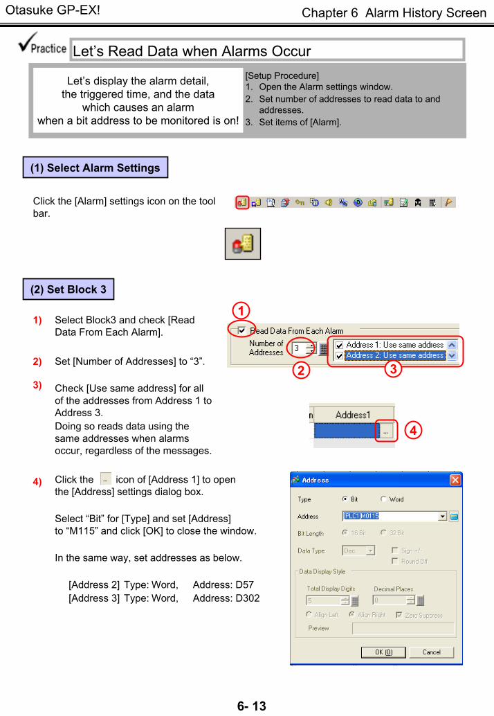
Let’s Read Data when Alarms Occur
(1) Select Alarm Settings
Click the [Alarm] settings icon on the tool bar.
(2) Set Block 3
1Select Block3 and check [Read Data From Each Alarm].
1)
2 3Set [Number of Addresses] to “3”.
Check [Use same address] for all of the addresses from Address 1 to Address 3.Doing so reads data using the same addresses when alarms occur, regardless of the messages.
2)
3)
4
Click the icon of [Address 1] to open the [Address] settings dialog box.
Select “Bit” for [Type] and set [Address] to “M115” and click [OK] to close the window.
In the same way, set addresses as below.
[Address 2] Type: Word, Address: D57[Address 3] Type: Word, Address: D302
4)

Otasuke GP-EX!
6- 14
Chapter 6 Alarm History Screen
(3) Item Settings
1) Open the base screen “6” and double-click the placed alarm. Select the [Item] tab.
1
2
Check [Address] and set [Display Characters] to “6”.
Check from [Address 1] to [Address 3] and set the item names as follows. Address 1: AutoAddress 2: SpdAddress 3: Qty
2)
Click!
Separator When you set [Address], a “separator” appears in the Display Order field. On the GP, you can display the items above the separator without scrolling.
Date Time Error Press. Temp. Flow Rate Power speed2007/5/31 10:02:00 Heater Error 20 800 49 199 502007/5/31 10:03:01 A/C Overheat 10 120 43 200 482007/5/31 10:12:18 Heater Error 10 80 22 201 482007/5/31 10:32:57 Freezer Fan Error 7 65 31 200 49
One Point
< >

Otasuke GP-EX!
6- 15
Chapter 6 Alarm History Screen
Let’s place a switch to edit alarm messages!
[Setup Procedure]
1. Open the base screen “6”.
2. Make the Switch settings for the Alarm.
Let’s Edit Alarm Message
1(1)Switch Settings
1)
2)
3)
2
Open the base screen, [6] and click the [Switch] icon on the tool bar.
Place the switch on the location on the right figure by drag.
2)
(1)Switch Settings 2
3
4
5
Double click the placed switch to open the dialog box.
1)
Select [Special Switch] on the [Switch Feature] tab.
Set [Alarm History Switch] for [Special Action] and [Start] for [Action].
Select the shape you like in [Select Shape].
4)
5) Enter [Strt] on the [Label] tab and click [OK].
Otasuke GP-EX!
6- 16
Chapter 6 Alarm History Screen
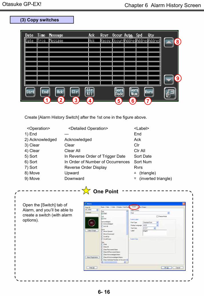
(3) Copy switches
1 2 3 4 5 6 7
9
8
Create [Alarm History Switch] after the 1st one in the figure above.
<Operation> <Detailed Operation> <Label>1) End --- End2) Acknowledged Acknowledged Ack3) Clear Clear Clr4) Clear Clear All Clr All5) Sort In Reverse Order of Trigger Date Sort Date6) Sort In Order of Number of Occurrences Sort Num7) Sort Reverse Order Display Rvrs8) Move Upward △ (triangle)9) Move Downward ▽ (inverted triangle)
One Point
Open the [Switch] tab of Alarm, and you’ll be able to create a switch (with alarm options).

Otasuke GP-EX!
6- 17
Chapter 6 Alarm History Screen
Alarm History Switch
Alarm History Switch: Types and Actions
Types of Switches Description
Start
If you touch [Start], a cursor will appear to operate the history. When the Freeze Mode is set, it suspends the currently displayed alarms by touching [Start] twice and prohibits the screen display from refreshing even when an alarm occurs, is acknowledged, or is recovered. To cancel the Freeze Mode, touch [End]. When you cancel it, the stored alarms will be all refreshed and displayed at one time.
End If you touch [End], the cursor will disappear and the key operation will be terminated.
Acknowledge Shows the acknowledged time in the selected message. Acknowledge All Shows the acknowledged times in all of the displayed messages. Move Upward Moves the cursor one row up.Move Downward Moves the cursor one row down.Scroll Up Moves the cursor up by a given number of rows. Scroll Down Moves the cursor down by a given number of rows. Clear Erases the selected message. Clear All Erases all the displayed messages. Clear Recovery Alarm Erases the selected alarm, which has been recovered.Clear All Recovery Alarms
Erases all the recovered alarms.
Clear Acknowledged Alarm
Erases the selected alarm which has been acknowledged.
Clear All Acknowledged Alarm
Erases all the acknowledged alarms.
Clear Individual Number of Occurrences
Clears the number of occurrences of the selected message.
Clear All Number of Occurrences
Clears all the numbers of occurrences of the displayed messages.
Clear Individual Accumulated Time
Clears the accumulate time of the selected message.
Clear All Accumulated Time
Clears all the accumulate times of the displayed messages.
In Reverse Order of Trigger Date
Displays alarm messages in order of latest occurrence.
Sort
Clear
In Number of Occurrences Order
Displays alarm messages in descending order of occurrence frequency.
In Descending Order of Accumulated Time
Displays alarm messages in descending order of accumulated time.
Level & In Reverse Order of Trigger Date
Displays alarm messages in descending order of level. If multiple messages with the same level exist, they will be displayed in order of latest occurrence.
Level & In Descending Order of Number of Occurrences
Displays alarm messages in descending order of level. If multiple messages with the same level exist, they will be displayed in descending order of occurrence frequency.
Alarm Registration Order
Displays alarm messages in order of registration.
Reverse Order Displays alarm messages in reverse order of the current sorting.Sub Display Displays a sub screen of the selected message.
Alarm Number Acquisition Obtains the alarm message number (the row number registered in [Alarm]) of the message at the current cursor position.
Move
Acknowledge

Otasuke GP-EX!
6- 18
Chapter 6 Alarm History Screen
To display details or countermeasures of each alarm message, use the “Sub Display” feature. Touching a displayed alarm message directly displays a sub screen.
Example of Sub Display
1) Touch a displayed alarm message directly.
2) A sub screen corresponding to the selected alarm message will appear.
1
2
Display Details/Countermeasures of Each Alarm
One Point
Entering the extended settings screen allows you to create a sub window displaying images, movies, etc.
Sub Display
For details, see GP-Pro EX Reference Manual Chapter 19 Alarms, Chapter 27 Recording and Playing Video
Otasuke GP-EX!
6- 19
Chapter 6 Alarm History Screen
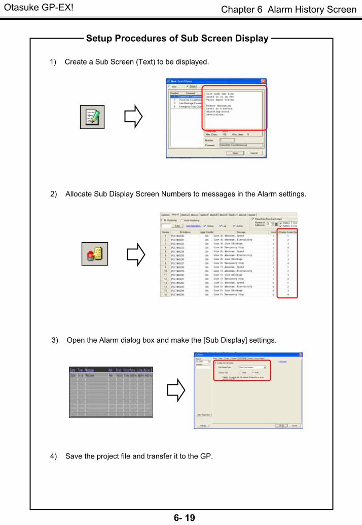
1) Create a Sub Screen (Text) to be displayed.
2) Allocate Sub Display Screen Numbers to messages in the Alarm settings.
3) Open the Alarm dialog box and make the [Sub Display] settings.
Setup Procedures of Sub Screen Display
4) Save the project file and transfer it to the GP.

Otasuke GP-EX!
6- 20
Chapter 6 Alarm History Screen
Let’s display details by touching each alarm message directly!
[Setup Procedure]
1. Create a Sub Display screen.
2. Register the Sub Display Screen Number.
3. Make the Sub Display settings of Alarm.
Let’s Display Details of Each Alarm Message
(1) Create Sub Screen
On the [Common Settings] menu, select [Text Registration]. Or click the [Text Registration]
icon on the tool bar.
* In this practice project file, comments are registered as texts beforehand.
(2) Set Sub Display Screen Number
11) Select the [Alarm] settings icon on
the tool bar.
2) Register [Sub Display Screen Number] for each alarm message as shown right.
2
Otasuke GP-EX!
6- 21
Chapter 6 Alarm History Screen
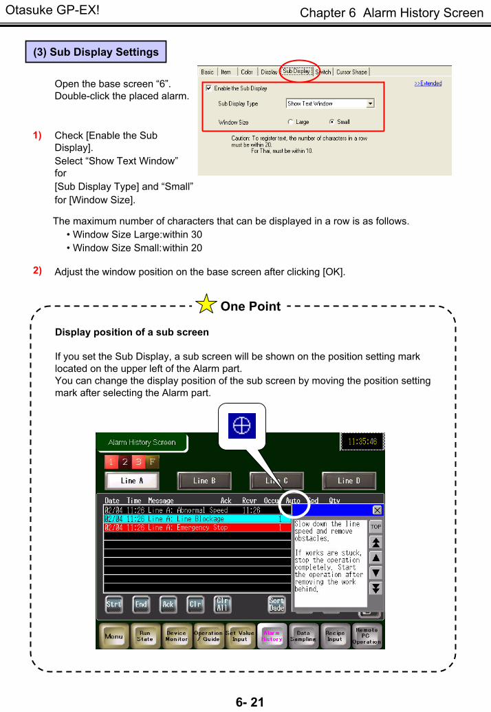
(3) Sub Display Settings
Open the base screen “6”. Double-click the placed alarm.
1) Check [Enable the Sub Display]. Select “Show Text Window”for [Sub Display Type] and “Small”for [Window Size].
The maximum number of characters that can be displayed in a row is as follows. • Window Size Large:within 30• Window Size Small:within 20
2) Adjust the window position on the base screen after clicking [OK].
Display position of a sub screen
If you set the Sub Display, a sub screen will be shown on the position setting mark located on the upper left of the Alarm part.You can change the display position of the sub screen by moving the position setting mark after selecting the Alarm part.
One Point
Otasuke GP-EX!
6- 22
Chapter 6 Alarm History Screen
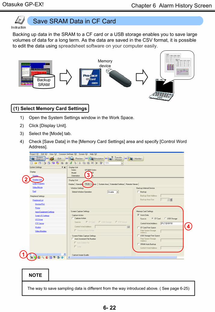
Save SRAM Data in CF Card
Backing up data in the SRAM to a CF card or a USB storage enables you to save large volumes of data for a long term. As the data are saved in the CSV format, it is possible to edit the data using spreadsheet software on your computer easily.
Memory device
BackupSRAM
(1) Select Memory Card Settings
1) Open the System Settings window in the Work Space.
2) Click [Display Unit].
3) Select the [Mode] tab.
4) Check [Save Data] in the [Memory Card Settings] area and specify [Control Word Address].
4
1
23
NOTE
The way to save sampling data is different from the way introduced above. ( See page 6-25)
Otasuke GP-EX!
6- 23
Chapter 6 Alarm History Screen
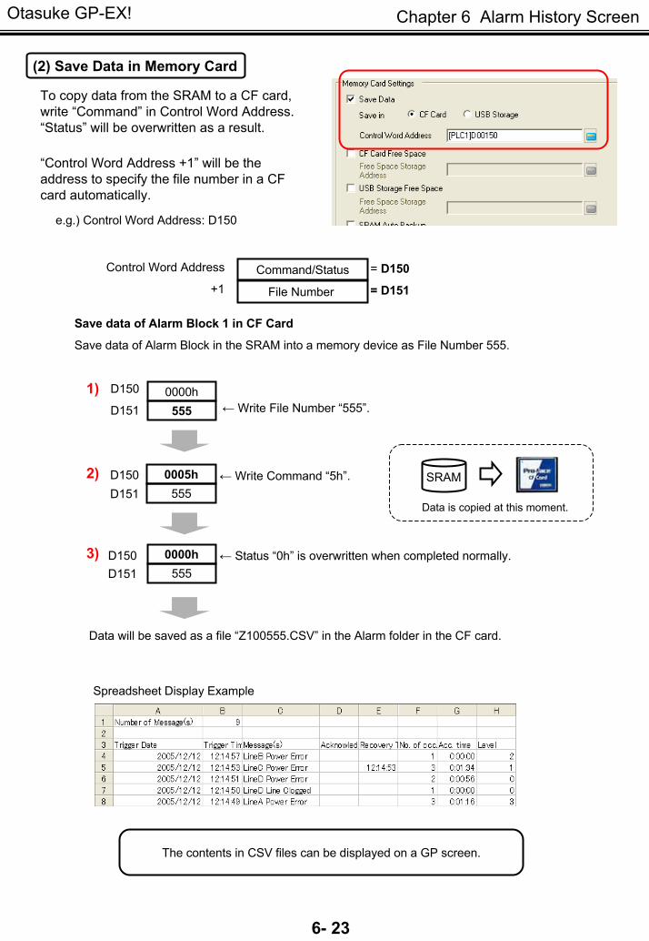
To copy data from the SRAM to a CF card, write “Command” in Control Word Address. “Status” will be overwritten as a result.
“Control Word Address +1” will be the address to specify the file number in a CF card automatically.
Command/Status
File Number
e.g.) Control Word Address: D150
(2) Save Data in Memory Card
Save data of Alarm Block in the SRAM into a memory device as File Number 555.
D150 D151
1)
2)
0000h555
Save data of Alarm Block 1 in CF Card
Control Word Address
+1 = D151
= D150
3)
D150D151
0005h555
SRAM
Data is copied at this moment.
← Write File Number “555”.
← Write Command “5h”.
0000h555
D150 ← Status “0h” is overwritten when completed normally. D151
Data will be saved as a file “Z100555.CSV” in the Alarm folder in the CF card.
Spreadsheet Display Example
The contents in CSV files can be displayed on a GP screen.
Otasuke GP-EX!
6- 24
Chapter 6 Alarm History Screen
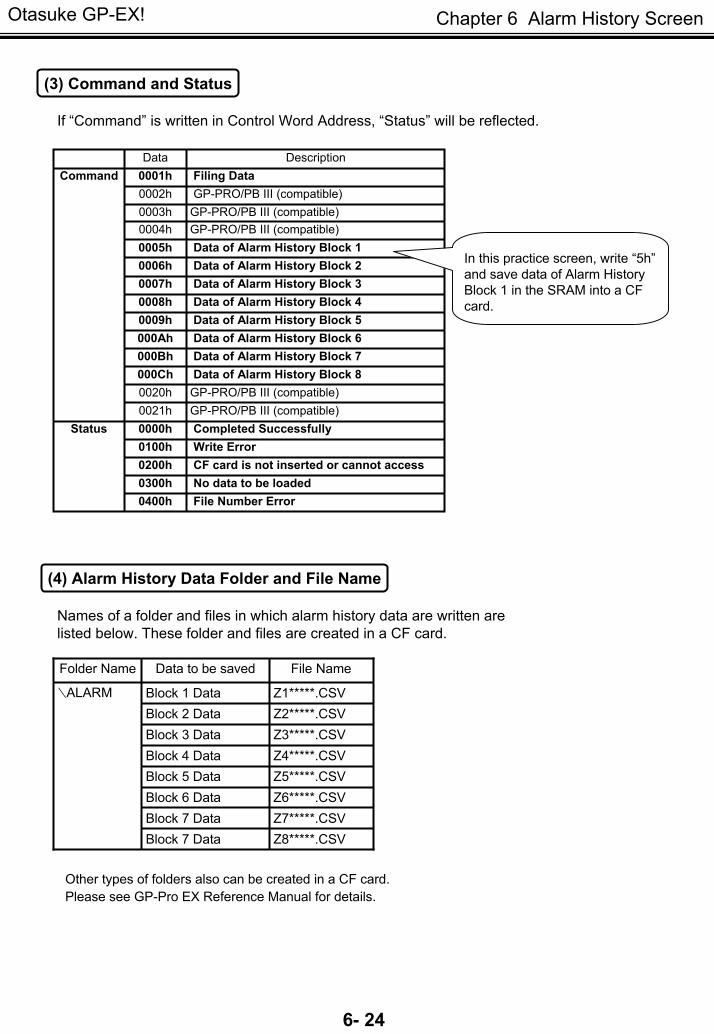
Data Description0001h Filing Data0002h GP-PRO/PB III (compatible) 0003h GP-PRO/PB III (compatible) 0004h GP-PRO/PB III (compatible) 0005h Data of Alarm History Block 10006h Data of Alarm History Block 20007h Data of Alarm History Block 30008h Data of Alarm History Block 40009h Data of Alarm History Block 5000Ah Data of Alarm History Block 6000Bh Data of Alarm History Block 7000Ch Data of Alarm History Block 8 0020h GP-PRO/PB III (compatible) 0021h GP-PRO/PB III (compatible) 0000h Completed Successfully0100h Write Error0200h CF card is not inserted or cannot access0300h No data to be loaded0400h File Number Error
Status
Command
(3) Command and Status
If “Command” is written in Control Word Address, “Status” will be reflected.
In this practice screen, write “5h”and save data of Alarm History Block 1 in the SRAM into a CF card.
(4) Alarm History Data Folder and File Name
Names of a folder and files in which alarm history data are written are listed below. These folder and files are created in a CF card.
Z6*****.CSVBlock 6 DataZ7*****.CSVBlock 7 DataZ8*****.CSVBlock 7 Data
Z5*****.CSVBlock 5 DataZ4*****.CSVBlock 4 DataZ3*****.CSVBlock 3 DataZ2*****.CSVBlock 2 DataZ1*****.CSVBlock 1 Data∖ALARM
File NameData to be savedFolder Name
Other types of folders also can be created in a CF card. Please see GP-Pro EX Reference Manual for details.
Otasuke GP-EX!
6- 25
Chapter 6 Alarm History Screen
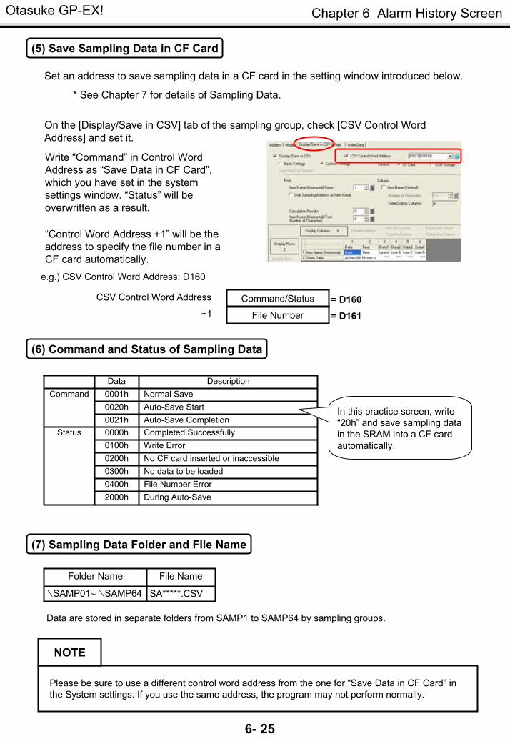
(5) Save Sampling Data in CF Card
Set an address to save sampling data in a CF card in the setting window introduced below.
* See Chapter 7 for details of Sampling Data.
On the [Display/Save in CSV] tab of the sampling group, check [CSV Control Word Address] and set it.
Please be sure to use a different control word address from the one for “Save Data in CF Card” in the System settings. If you use the same address, the program may not perform normally.
NOTE
Command/Status
File Number
CSV Control Word Address
+1 = D161= D160
Write “Command” in Control Word Address as “Save Data in CF Card”, which you have set in the system settings window. “Status” will be overwritten as a result.
“Control Word Address +1” will be the address to specify the file number in a CF card automatically.
e.g.) CSV Control Word Address: D160
(6) Command and Status of Sampling Data
Data Description0001h Normal Save0020h Auto-Save Start0021h Auto-Save Completion0000h Completed Successfully0100h Write Error0200h No CF card inserted or inaccessible 0300h No data to be loaded
Status
0400h File Number Error2000h During Auto-Save
Command
In this practice screen, write “20h” and save sampling data in the SRAM into a CF card automatically.
(7) Sampling Data Folder and File Name
SA*****.CSV∖SAMP01∼ ∖SAMP64
File NameFolder Name
Data are stored in separate folders from SAMP1 to SAMP64 by sampling groups.
Otasuke GP-EX!
6- 26
Chapter 6 Alarm History Screen
B101 Memory Card Saving Screen
B102 CSV Display Screen
One Point
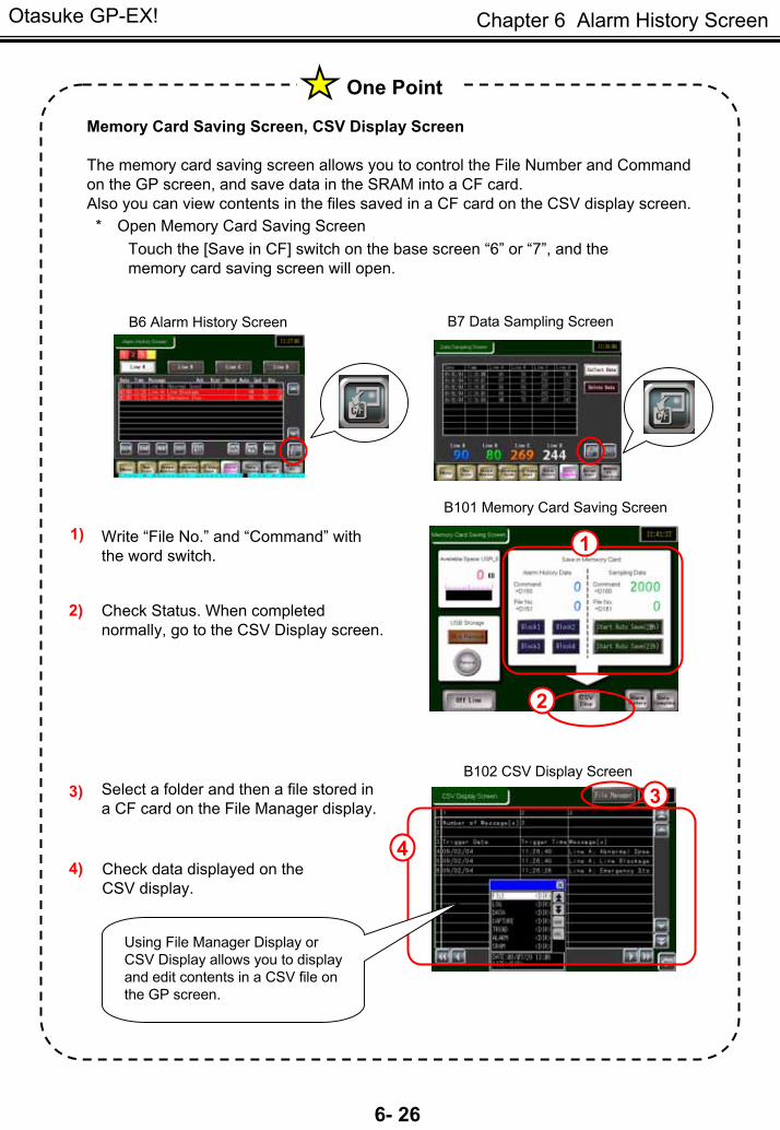
Memory Card Saving Screen, CSV Display Screen
The memory card saving screen allows you to control the File Number and Command on the GP screen, and save data in the SRAM into a CF card. Also you can view contents in the files saved in a CF card on the CSV display screen. * Open Memory Card Saving Screen
Touch the [Save in CF] switch on the base screen “6” or “7”, and the memory card saving screen will open.
Write “File No.” and “Command” with the word switch.
1)
Check Status. When completed normally, go to the CSV Display screen.
2)
Select a folder and then a file stored in a CF card on the File Manager display.
3)
Check data displayed on the CSV display.
4)
2
3
4
1
B6 Alarm History Screen B7 Data Sampling Screen
Using File Manager Display or CSV Display allows you to display and edit contents in a CSV file on the GP screen.
Otasuke GP-EX!
6- 27
Chapter 6 Alarm History Screen
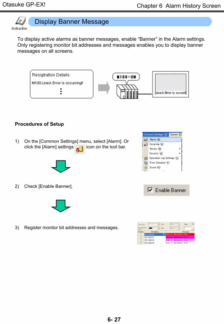
Display Banner Message
To display active alarms as banner messages, enable “Banner” in the Alarm settings. Only registering monitor bit addresses and messages enables you to display banner messages on all screens.
Procedures of Setup
1) On the [Common Settings] menu, select [Alarm]. Or click the [Alarm] settings icon on the tool bar.
2) Check [Enable Banner].
3) Register monitor bit addresses and messages.
Otasuke GP-EX!
6- 28
Chapter 6 Alarm History Screen
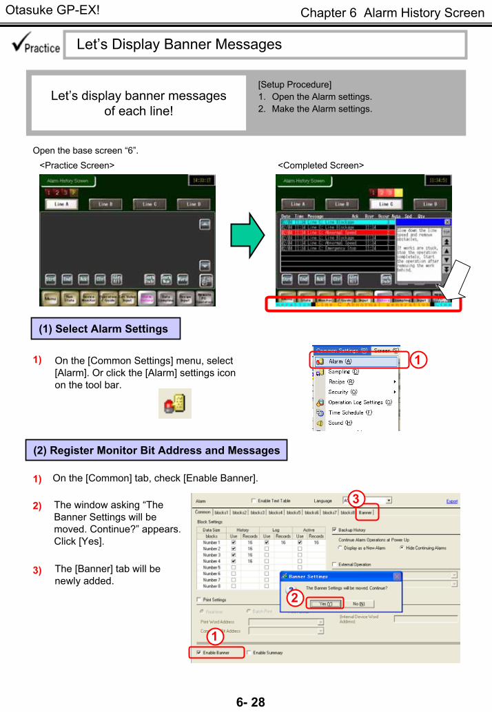
Let’s Display Banner Messages
Let’s display banner messages of each line!
[Setup Procedure]1. Open the Alarm settings.2. Make the Alarm settings.
Open the base screen “6”. <Practice Screen> <Completed Screen>
(1) Select Alarm Settings
11) On the [Common Settings] menu, select [Alarm]. Or click the [Alarm] settings icon on the tool bar.
(2) Register Monitor Bit Address and Messages
On the [Common] tab, check [Enable Banner]. 1)
3) The [Banner] tab will be newly added.
3
1
The window asking “The Banner Settings will be moved. Continue?” appears. Click [Yes].
2)
2

Otasuke GP-EX!
6- 29
Chapter 6 Alarm History Screen
4
5
4) Set [Text Color], [Font], [Size], and [Background Color]. If you set [Blink], you can blink each color.
Set bit addresses to be monitored in [Bit Address] and messages to be displayed in [Message]. If [Print at Trigger Time] and [Print at Recovery Time] are set to ON and a printer is connected to the GP display, messages will be printed out at each status.
Here, set [Bit Address], [Message], [[Print at Trigger Time] and [Print at Recovery Time] as above.
5)
(3) Save
Click the [Save] icon on the tool bar.
Check the performance in the Simulation mode.
Or F12 key
NOTE
If any switches are behind the banner messages, touching the hidden part is unavailable. Please be sure to place parts, such as switches, not to hide behind the banner messages. NG
Otasuke GP-EX!
6- 30
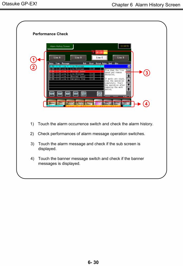
Chapter 6 Alarm History Screen
1) Touch the alarm occurrence switch and check the alarm history.
2) Check performances of alarm message operation switches.
3) Touch the alarm message and check if the sub screen is displayed.
4) Touch the banner message switch and check if the banner messages is displayed.
Performance Check
12
3
4
Otasuke GP-EX!
6- 31
Chapter 6 Alarm History Screen
MEMO