Semiconductor Device Engineering and Crosslight...
31
Lighting up the Semiconductor World… www.crosslight.com Semiconductor Device Engineering and Crosslight TCAD
Transcript of Semiconductor Device Engineering and Crosslight...
Lighting up the Semiconductor World…
www.crosslight.com
Semiconductor Device Engineering and
Crosslight TCAD
www.crosslight.com
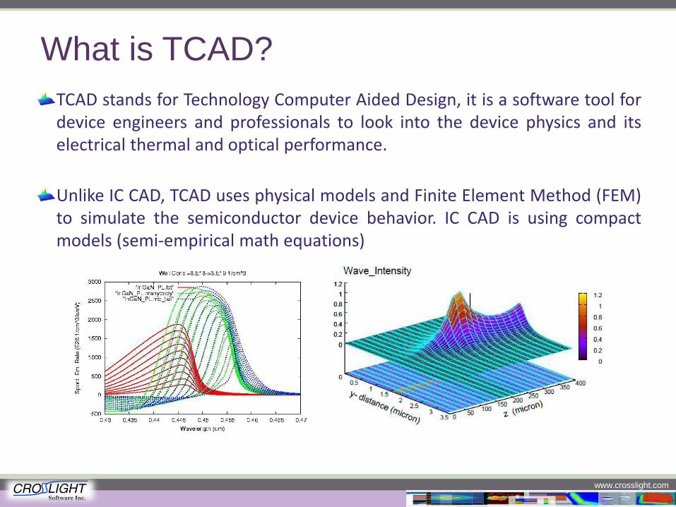
What is TCAD?
TCAD stands for Technology Computer Aided Design, it is a software tool for device engineers and professionals to look into the device physics and its electrical thermal and optical performance.
Unlike IC CAD, TCAD uses physical models and Finite Element Method (FEM) to simulate the semiconductor device behavior. IC CAD is using compact models (semi-empirical math equations)
Lighting up the Semiconductor World…
www.crosslight.com
Lighting Up the Semiconductor World:
About Crosslight TCAD
www.crosslight.com
A Glimpse
A leading TCAD provider since 1993 The world’s No.1 TCAD simulator for optics and photonics application The world’s first commercial TCAD for Laser Diode Customer list extends to hundreds of companies, research institutions and
universities world wide. Complete product portfolio for 2D/3D semiconductor device simulation Café-time Simulator. Windows based, user friendly GUI makes simulation more
enjoyable.
www.crosslight.com
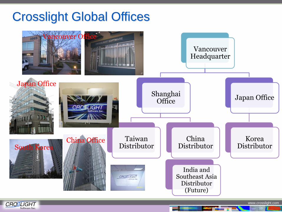
Crosslight Global Offices
Vancouver Headquarter
Shanghai Office
Taiwan Distributor
China Distributor
Japan Office
Korea Distributor
Vancouver Office
Japan Office
South Korea China Office
India and Southeast Asia
Distributor (Future)
www.crosslight.com
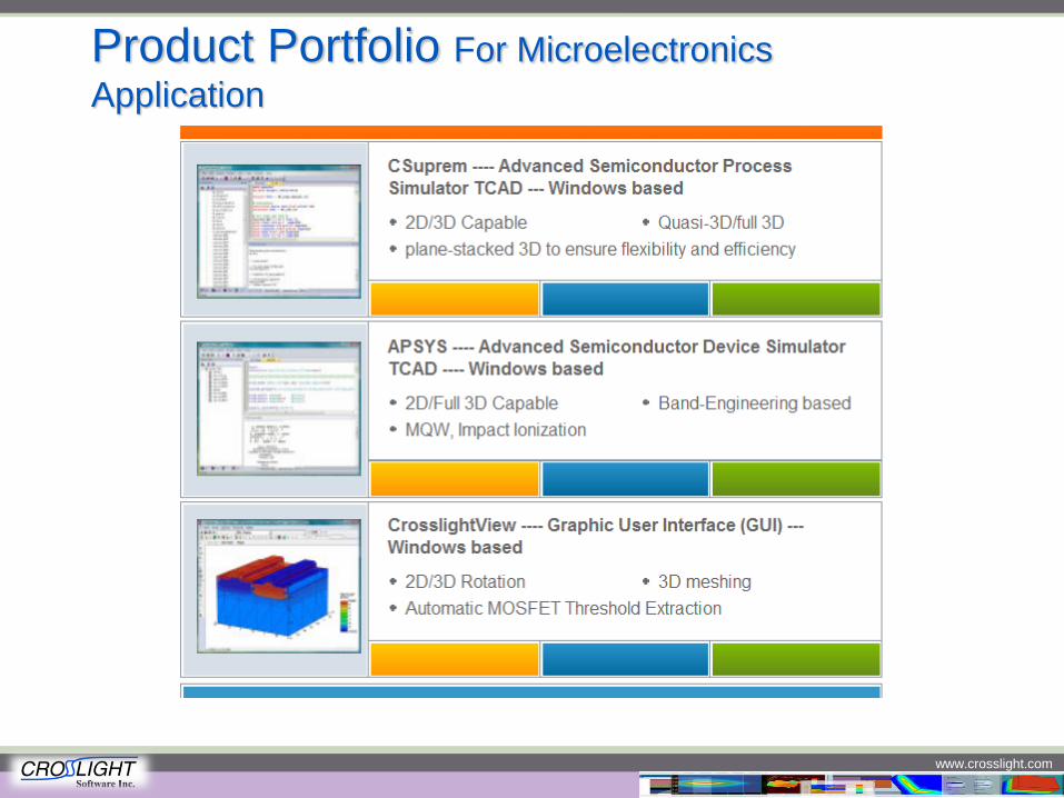
Product Portfolio For Microelectronics
Application

www.crosslight.com
CSUPREM Features
Originated from Stanford University’s Suprem IV, 2D/3D capable Innovative simulation tools to ensure a fast and seamlessly transfer from process to
device simulation Stacked3D technology enables ultra efficient 3D structure combined with powerful and
easy to use 3D editor to provide class leading 3D simulation experience Windows based and user friendly Graphic User Interface (GUI) AutoTCAD for generating a series of simulations from parameter variations, perfect for
overnight simulations Embedded easy 2D/3D setup tool, grammar check tool, point and show wizard help and
tutorial movies for a jump start
Lighting up the Semiconductor World…
www.crosslight.com
3D Simulation of Semiconductor
Devices Using MaskEditor
www.crosslight.com
About3D Simulation
Why 3D?
Device is 3D in nature, lots of devices need 3D simulation for better accuracy. For example, Superjunction LDMOS, metal interconnect, etc.
Do you need 3D Simulation?
Does your device have variation along the third (z) dimension ? Do you want to examine some peripheral behavior of the device, like fringe current at
the corner of race-track shaped gate? Does your device have a special shape from top down view? (like CMOS Image Sensor,
or HEXFET)?
Challenges for 3D Simulation:
Extremely time consuming. As hard as it may be to believe, traditional 3d simulation time may be longer than the actual fabrication time for large power semiconductor devices.
Difficult to build the structure and optimize the mesh.
www.crosslight.com
Crosslight’s Approach of 3D Simulation
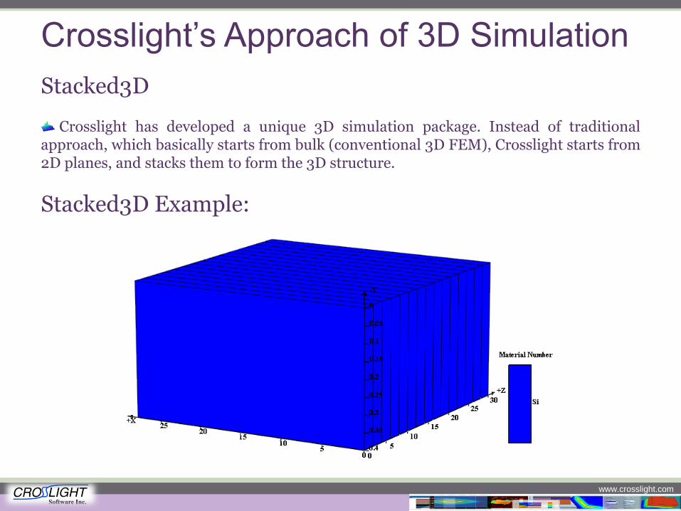
Stacked3D
Crosslight has developed a unique 3D simulation package. Instead of traditional approach, which basically starts from bulk (conventional 3D FEM), Crosslight starts from 2D planes, and stacks them to form the 3D structure.
Stacked3D Example:
www.crosslight.com
Advantages of Stacked3D
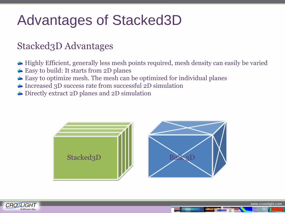
Stacked3D Advantages
Highly Efficient, generally less mesh points required, mesh density can easily be varied Easy to build: It starts from 2D planes Easy to optimize mesh. The mesh can be optimized for individual planes Increased 3D success rate from successful 2D simulation Directly extract 2D planes and 2D simulation
Stacked3D Bulk 3D
www.crosslight.com
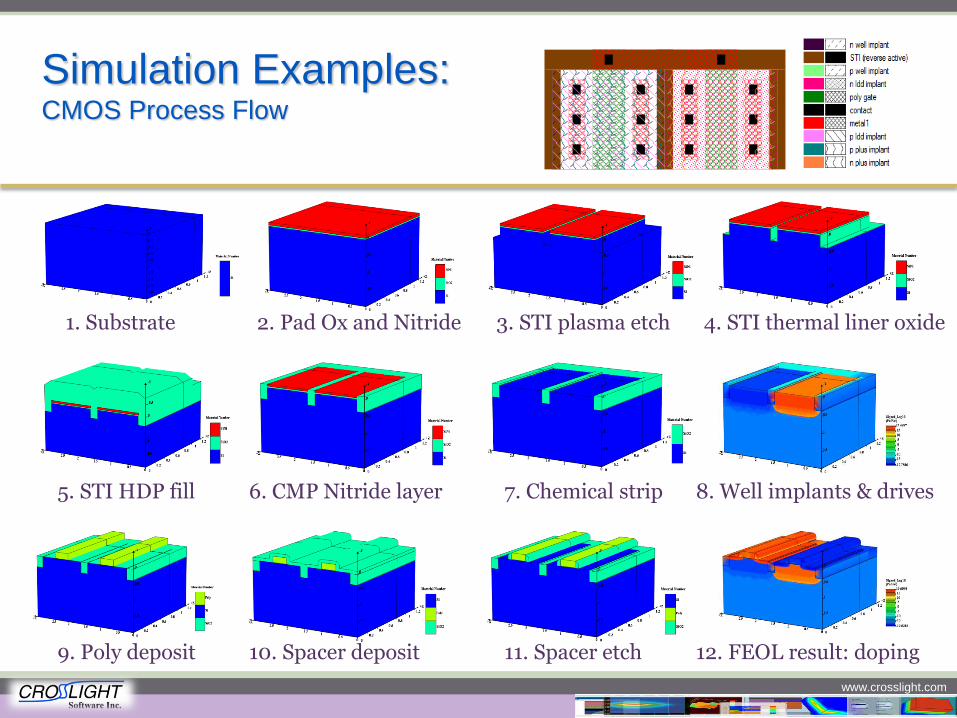
Simulation Examples: CMOS Process Flow
1. Substrate 2. Pad Ox and Nitride 3. STI plasma etch 4. STI thermal liner oxide
5. STI HDP fill 6. CMP Nitride layer 7. Chemical strip 8. Well implants & drives
9. Poly deposit 10. Spacer deposit 11. Spacer etch 12. FEOL result: doping
www.crosslight.com
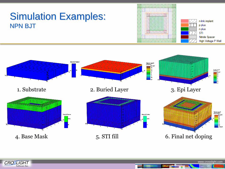
Simulation Examples: NPN BJT
1. Substrate 2. Buried Layer 3. Epi Layer
4. Base Mask 5. STI fill 6. Final net doping
www.crosslight.com
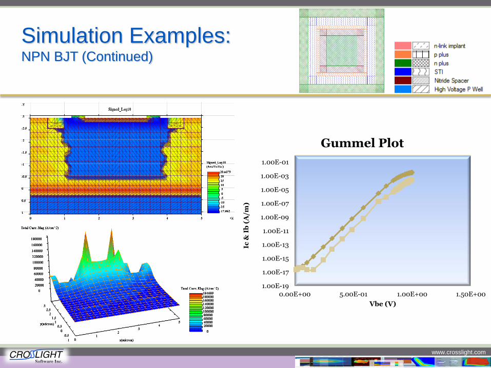
Simulation Examples: NPN BJT (Continued)
1.00E-19
1.00E-17
1.00E-15
1.00E-13
1.00E-11
1.00E-09
1.00E-07
1.00E-05
1.00E-03
1.00E-01
0.00E+00 5.00E-01 1.00E+00 1.50E+00
Ic
& I
b (
A/m
)
Vbe (V)
Gummel Plot
www.crosslight.com
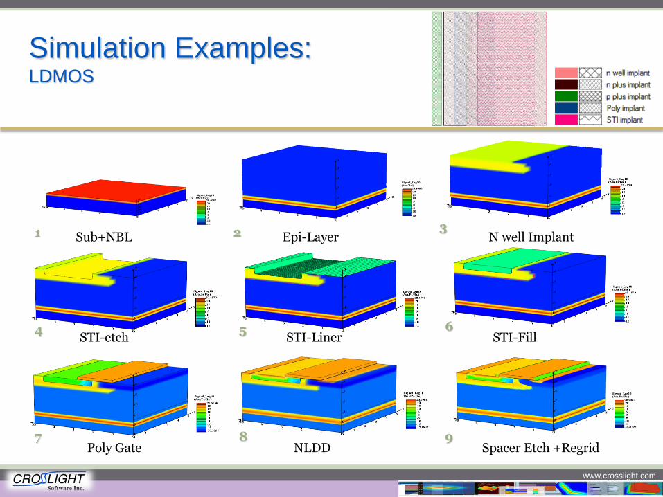
Simulation Examples: LDMOS
Sub+NBL Epi-Layer N well Implant
STI-etch STI-Liner STI-Fill
Poly Gate NLDD Spacer Etch +Regrid
1 2 3
4 5 6
7 8 9
www.crosslight.com
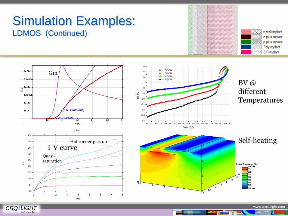
Simulation Examples: LDMOS (Continued)
Quasi-saturation
Hot carrier pick up
I-V curve
Gm
0 5 10 15 20 25 30 35 40 45 50 55 60 65 70 75 80 85 90
-14
-13
-12
-11
-10
-9
-8
-7
-6
-5
-4
Ids
(A)
Vds (V)
300K
350K
400K
450K
Self-heating
BV @ different Temperatures
www.crosslight.com
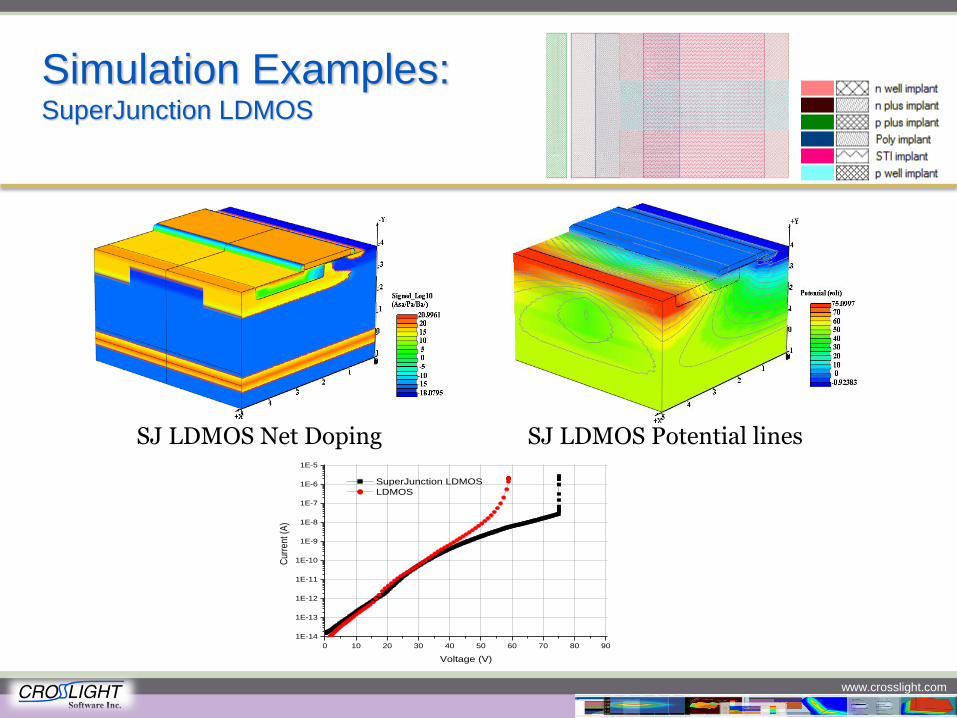
Simulation Examples: SuperJunction LDMOS
SJ LDMOS Net Doping SJ LDMOS Potential lines
0 10 20 30 40 50 60 70 80 90
1E-14
1E-13
1E-12
1E-11
1E-10
1E-9
1E-8
1E-7
1E-6
1E-5
Cur
rent
(A
)
Voltage (V)
SuperJunction LDMOS
LDMOS
Lighting up the Semiconductor World…
www.crosslight.com
2D Simulation of MOSFET Threshold
Voltage Using AutoTCAD
A New Batch Testing and Design of Experiments Tool
www.crosslight.com
What is Design of Experiments for
TCAD?
Suppose you are a device engineer, responsible for the design a MOSFET Now, you have a target for threshold voltage, for example, 1.2V. You want to know how
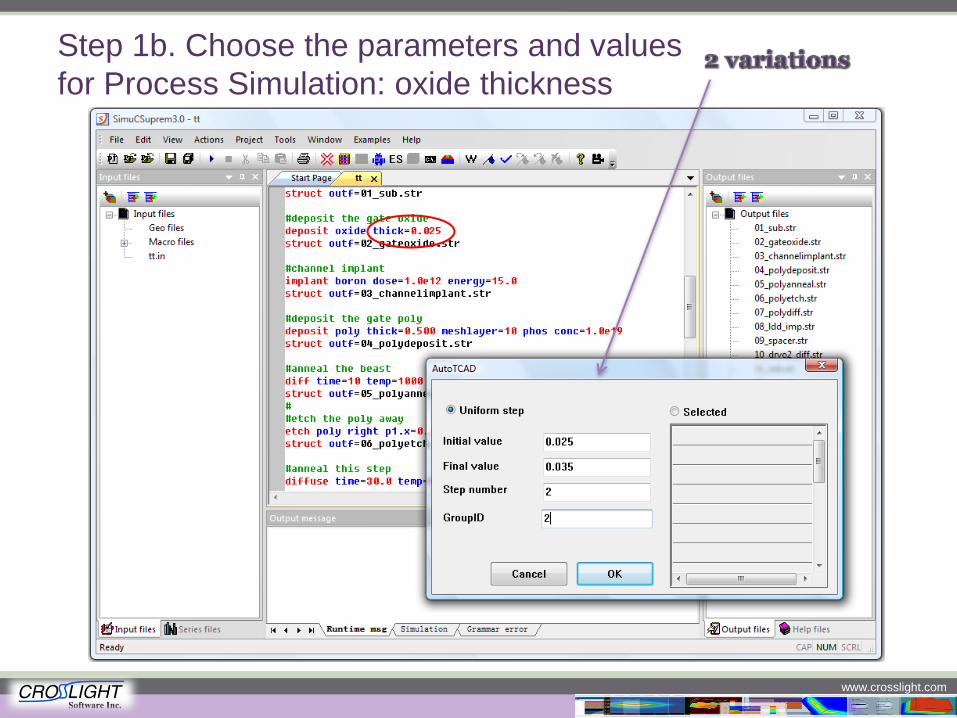
to choose the gate oxide thickness and body(channel) doping For gate oxide, suppose you have two choices, one is 25nm, the other is 35nm, while for
body doping, you have two choices for both energy and dose Windows based and user friendly Graphic User Interface (GUI) AutoTCAD for generating a series of simulations from parameter variations, perfect for
overnight simulations Embedded easy 2D/3D setup tool, syntax check tool, point and show wizard help and
tutorial movies for a jump start
www.crosslight.com
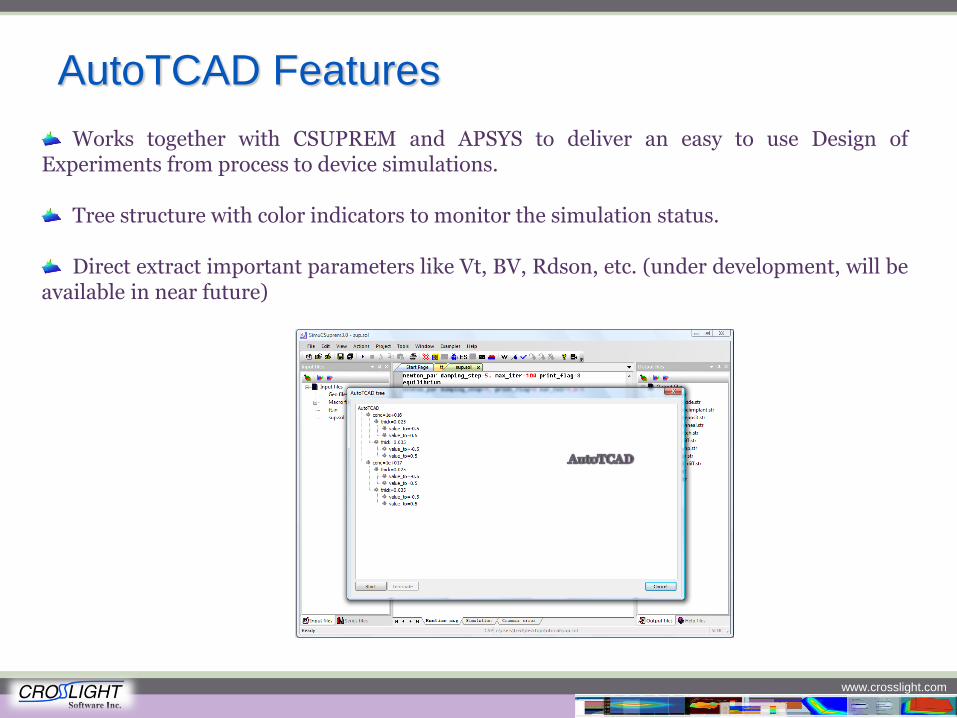
AutoTCAD Features
Works together with CSUPREM and APSYS to deliver an easy to use Design of Experiments from process to device simulations.
Tree structure with color indicators to monitor the simulation status. Direct extract important parameters like Vt, BV, Rdson, etc. (under development, will be
available in near future)
www.crosslight.com
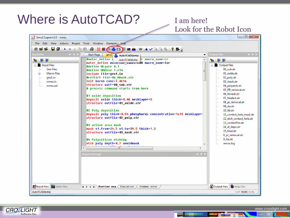
Where is AutoTCAD? I am here! Look for the Robot Icon
www.crosslight.com
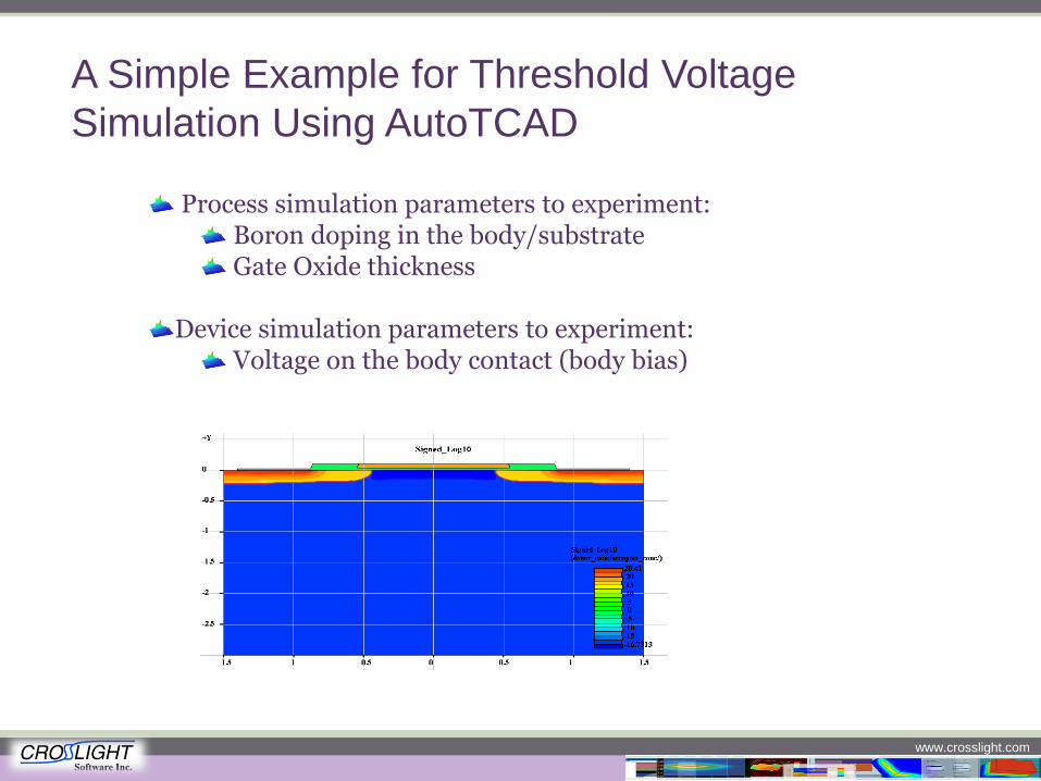
A Simple Example for Threshold Voltage
Simulation Using AutoTCAD
Process simulation parameters to experiment: Boron doping in the body/substrate Gate Oxide thickness
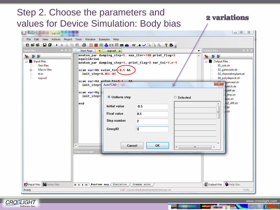
Device simulation parameters to experiment: Voltage on the body contact (body bias)
www.crosslight.com
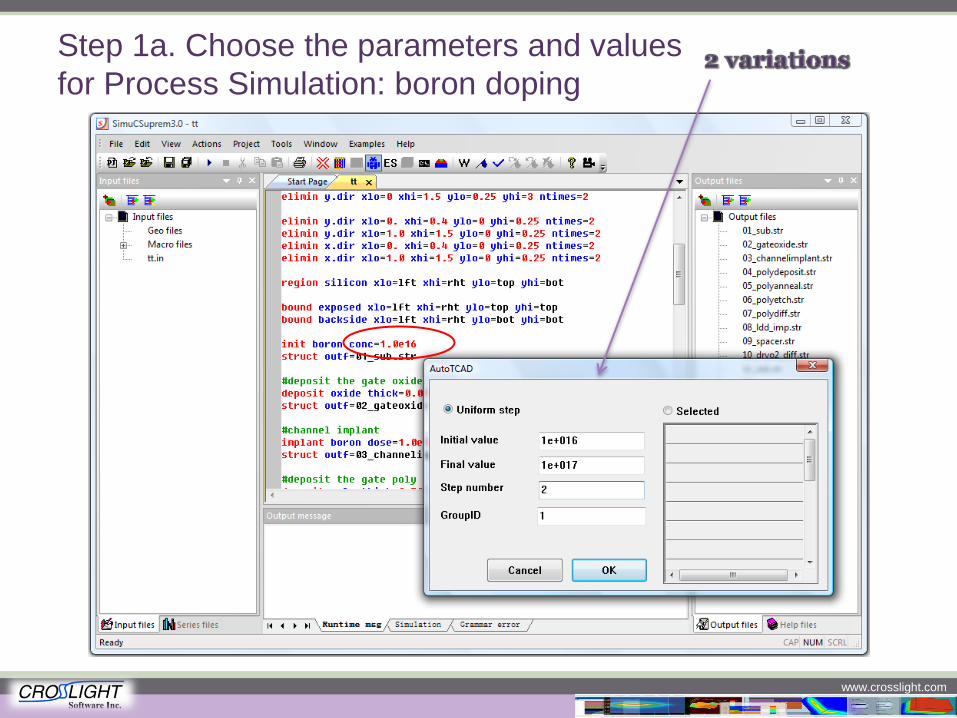
Step 1a. Choose the parameters and values
for Process Simulation: boron doping
www.crosslight.com
Step 1b. Choose the parameters and values
for Process Simulation: oxide thickness
www.crosslight.com
Step 2. Choose the parameters and
values for Device Simulation: Body bias
www.crosslight.com
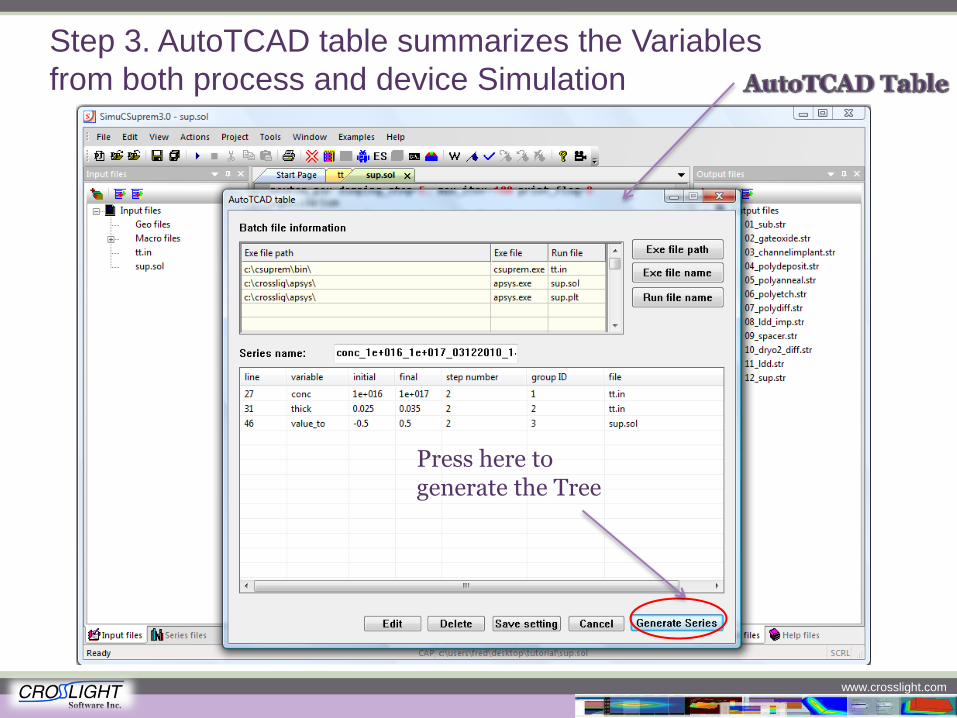
Step 3. AutoTCAD table summarizes the Variables
from both process and device Simulation
Press here to generate the Tree
www.crosslight.com
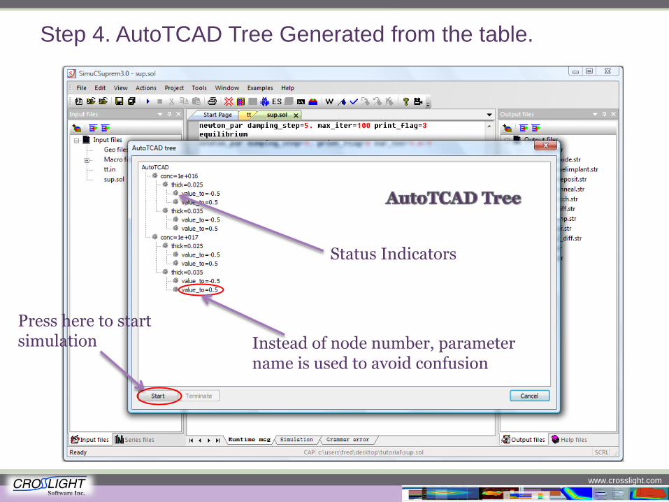
Step 4. AutoTCAD Tree Generated from the table.
Instead of node number, parameter name is used to avoid confusion
Press here to start simulation
Status Indicators
www.crosslight.com
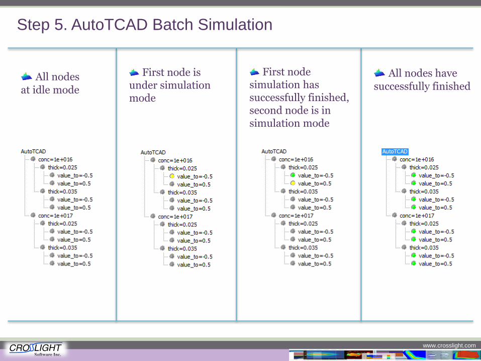
All nodes
at idle mode
First node is under simulation mode
First node simulation has successfully finished, second node is in simulation mode
Step 5. AutoTCAD Batch Simulation
All nodes have
successfully finished
www.crosslight.com
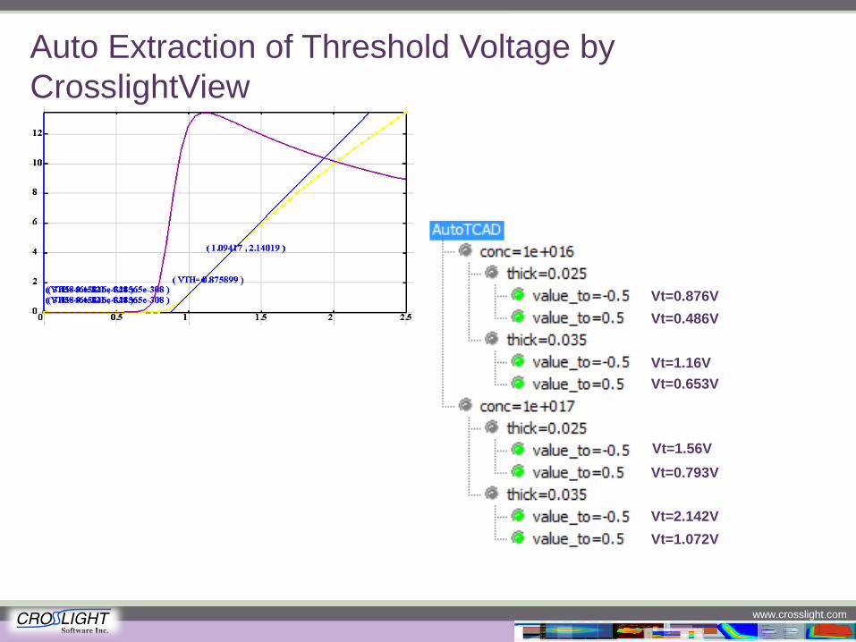
Auto Extraction of Threshold Voltage by
CrosslightView
Vt=0.876V
Vt=0.486V
Vt=1.16V
Vt=0.653V
Vt=1.56V
Vt=0.793V
Vt=2.142V
Vt=1.072V
www.crosslight.com
Ongoing improvements and near future
releases
Full release of AutoTCAD, with direct extraction of important parameters like BV, VT and Rdson in a couple of weeks. (The parameter extraction capability is ready, and is now being implemented to the AutoTCAD GUI)
New Release of SimuCenter, the most powerful GUI from Crosslight. SimuCenter will
act as a central hub to connect all the functions of Crosslight's products, and make the simulation experience even more enjoyable
Codeless Simulation. Iconize process steps and device simulation steps GPU-based solver to further accelerate 3D power semiconductor device simulation
www.crosslight.com