Model-Based Damper Control for Semi-Active Suspension Systems
Upload
saroj-babuCategory
view
23download
4description

CHAPTER-I
INTRODUCTION
In the present work, the shortcomings of conventional passive vehicle suspensions will be
discussed. Traditionally, in automotive suspension designs have been a compromise between
the two conflicting criteria of road holding and passenger comfort. The suspension system
must support the weight of the vehicle, provide directional control during handling, and
provide effective isolation of passengers and payload from road disturbances. A passive
suspension has the ability to store energy via a spring and to dissipate it via a damper. The
parameters are generally fixed, being chosen to achieve a certain level of compromise
between road holding and ride comfort. Once the spring has been selected based on the load-
carrying capability of the suspension, the damper is the only variable remaining to specify.
Low damping yields poor resonance control at the natural frequencies of the body (sprung
mass) and axle (unsprung mass), but provides the necessary high frequency isolation required
for a comfortable ride. Conversely, large damping results in good resonance control at the
expense of high frequency isolation. Due to these conflicting demands, suspension design has
had to be something of a compromise, largely determined by the type of use for which the
vehicle is designed.
1.1.1.Pitching:
1.1.2.Rolling:
1.2.Various kinds of suspension systems includes:
1)Passive suspension system.
2)Semi-active suspension system.
3)Active suspension system.

FIG::SUSPENSION SYSTEM IN CAR
1.2.1) Passive Vertical Quarter-Car Model:
When, suspension modelling and control are considered, the well-known vertical quarter-car
model is often used. This model allows us to study the vertical behaviour of a vehicle
according to the suspension type (passive or controlled). In this book, this model is largely
used for control design and for performance analysis. The passive (both general and
simplified forms)
Quarter-car model is shown.
FIG::PASSIVE SUSPENSION SYSTEM

2) SEMI-ACTIVE SUSPENSION SYSTEM:
The suspension system has been considered in many case studies of control design. Most of
the papers have been concerned with active suspensions, since they allow us to obtain greater
performances while the control synthesis does not require some dissipativity properties to be
handled. The semi-active suspension control literature is also quite large, and an important
number of control strategies exist for such a system. In this chapter, the most important or at
least the most developed ones, are recalled together with some “ad hoc” references. This
chapter aims at presenting and evaluating some of the usual existing control strategies. The
emphasis is mainly put on performance analysis, using the tools described, rather than on an
exhaustive and complete description. The chapter is organized as follows: some usual and
simple semi-active suspension strategies, focusing on comfort and road-holding respectively,
are presented and evaluated using the frequency response diagrams. Then, these strategies are
compared using the performance criteria presented. In, some modern semi-active methods are
also recalled but, due to their “complexity” (especially for performance tuning), only briefly
evaluated.
6.1 Comfort Oriented Semi-Active Control Approaches
In this section, the most common comfort oriented semi-active suspension control strategies
Skyhook Control
The principle of this approach is to design an active suspension control so that the chassis is
“linked” to the sky in order to reduce the vertical oscillations of the chassis and the axle
FIG:: Semi-Active Suspension Control Design for Vehicles

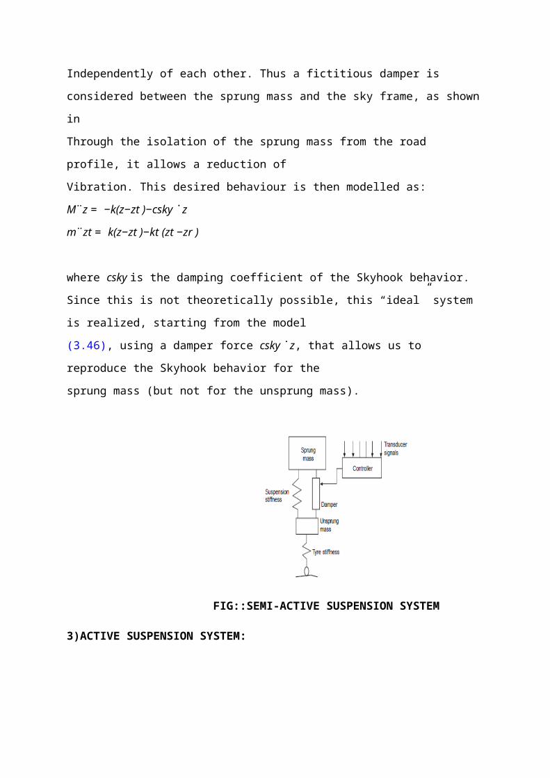
Independently of each other. Thus a fictitious damper is considered between the sprung mass
and the sky frame, as shown in
Through the isolation of the sprung mass from the road profile, it allows a reduction of
Vibration. This desired behaviour is then modelled as:
M¨z = −k(z−zt )−csky ˙z
m¨zt = k(z−zt )−kt (zt −zr )
where csky is the damping coefficient of the Skyhook behavior.
Since this is not theoretically possible, this “ideal” system is realized, starting from the model
(3.46), using a damper force csky ˙z, that allows us to reproduce the Skyhook behavior for the
sprung mass (but not for the unsprung mass).
FIG::SEMI-ACTIVE SUSPENSION SYSTEM
3)ACTIVE SUSPENSION SYSTEM:
FIG: :ACTIVE SUSPENSION SYSTEM
Quarter-Car Performance Specifications and Signals of Interest
Considering the previous remarks, and considering the quarter-car model given in
the following signals are considered for performance analysis and
Characterization of a suspension system:
• To evaluate the comfort, the vertical displacement z (or acceleration ¨z) of the chassis is
Analysed.
• To evaluate the road-holding, the tire deflection (zdeft ) is analysed.
• Eventually, the deflection limits (z min def and zmax def ) could be analysed.
FIG::A Quarter Car-model Suspension System.
Fig::Damping ratio trade-off

Two main conclusions can be drawn:
The fixed-damping configurations have an intrinsic trade-off: a low-damping provides Superior high-frequency filtering performance, but it is affected by a badly un-damped body resonance; on the other hand, a high-damping setting removes the resonances, but strongly deteriorates the filtering capabilities. Intermediate damping settings simply deliver different combinations of this trade-off.
A wise semi-active algorithm can (almost) completely remove the classical trade-off good damping of the body resonance can be guaranteed, together with good filtering performance.
Applications and Technologies of Semi-active Suspension SystemToday semi-active suspensions are used over a vast domain of applications. In vehicle applications, semi-active suspensions are used at different layers:
• At the (classical) wheel-to-chassis layer, in primary suspension systems.
• At the chassis-to-cabin layer, in large vehicles where the driver cabin is separated from the main chassis (e.g. large agricultural tractors, trucks, earth-moving machines, etc.).
• At the cabin-to-seat layer: in large off-road vehicles the driver seat is also frequently equipped with a fully-fledged suspension system, in order to reduce the vibration suffered by the driver during the typically long hours spent in the vehicle.
Many types of vehicle are equipped (or are being equipped) with semi-active suspension; thelist is long, multi-faceted, and continuously increasing. Such vehicles range from small vehicles like motorcycles, ATVs, snowmobiles, etc. to large off-road vehicles (agriculturalTractors, earth-moving machines, etc.), passing through classical cars, and duty-vehicles suchas trucks, ambulances, fire-trucks, etc.
If we look inside a semi-active damper, today there are three main available technologies,which allow a fast-reacting electronically controlled modification of the damping ratio of ashock absorber.
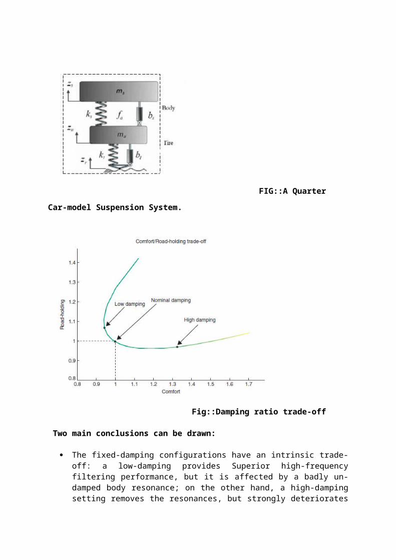
FIG:: Examples of electronically controlled semi-active shock absorbers, using threedifferent technologies. From left to right: solenoid-valve Electrohydraulic damper (Sachs),Magnetorheological damper (Delphi), and Electrorheological damper (Fludicon).
In a semi-active suspension system, the variation of damping may be achieved by introducing mouldable mechanisms in the shock absorber such as solenoid valves (electrohydraulic dampers), or by the use of fluids which may vary their viscosity if subject to an electric or magnetic field (electrorheological and magnetorheological dampers). A simple but effective description of this kind of actuator is extremely important for control design purposes.
Introduction to Suspension Modeling:
The graphical representation of a suspension system in a vehicle, where the so-called quarter-car model is depicted. The quarter-car aims at describing the interactions between the suspension system, the tire and the chassis in a single corner of a vehicle.As is evident from, the quarter-car representation consists of four simplified elements:
• The suspended mass representing the chassis.
• The unsprung mass that comprises devices such as the wheel mass, the brake, the caliper,etc.
• The tire that is modelled as an elastic element.
• The suspension system which consists of an elastic element and a dissipative element.

• The contributions of the elastic and dissipative elements are assumed to be additive.
Passive Suspension SystemsThis section presents the devices that are used for the elastic and the dissipative unit of passive Suspension. Coil and gas springs are usually adopted as elastic elements in the suspensions for vehicles: the coil springs exploit the elasticity provided by the torsion of coils; gas springs are based on the compressibility of gases. Dissipative devices are implemented by hydraulic shock absorbers.
Coil Spring
A coil spring (represented in figure below) is an elastic element assumed to be subject only to vertical forces and displacements. The force is delivered as a reaction of torsion of the coils, while other secondary effects may be neglected.
Fig::Example of a steel coil spring
2.3 Controllable Suspension Systems: a ClassificationIdeally, a control action may be introduced at different levels of the suspension system: at the level of the dissipative unit, by a modulation of the damping force; at the level of the elastic unit, by modulation of the spring force; at the full level of the suspension, by replacing both the elastic and the damping devices with a force actuator. This section presents the ideal classification of controllable suspensions, originally introducedby Isermann (2003).The classification of controllable suspension may be carried out according to the energy inputand the bandwidth of the actuator. More specifically, three features may be observed: thecontrollability range, in other words the range of forces that the actuators may deliver; thecontrol bandwidth which is a measure of how fast the actuator action is; the power requestthat is mainly due to the mix of controllability range and control bandwidth. The resultingclassification is concisely shown in Table below, which highlights five families of controllablesuspensions:• Adaptive suspension: the control action is represented by a relatively slow modulation ofdamping, so the control range is limited by the passivity constraint. The adaptive shockabsorber is characterized by a bandwidth of a few Hertz. Since no energy is introduced in

Table:: Classification of electronically controlled suspension
the system and the bandwidth is relatively small; the power request is usually limited to afew Watts.• Semi-active suspension: this system features an electronic shock absorber which mayvary the damping with a relatively large bandwidth (usually around 30–40Hz). Thedeliverable forces follow the passivity constraint of the damper, thus no energy may beintroduced into the system. Due to these features, the requested power is relatively low,around tens of Watts.• Load-levelling suspensions: This class of suspensions may be considered the first attempt at active suspensions, since they are capable of introducing energy in the system to change the steady state condition (as a response of a variation of the static load). The control acts on the parameter of the springs (usually an air spring). The bandwidth is usually within 0.1–1Hz, but the power request is usually some hundreds of Watts.
• Slow-active suspensions: In active suspensions, the passivity constraint is fully overcome and energy may be injected into the system. The control input is the suspension force FDelivered by an actuator which replaces the passive devices of the suspension. The bandwidth is limited to a few Hertz. Note that the vast controllability range is paid in terms of power request (around some kilo-Watts).
• Fully-active suspensions: The , difference between slow and fully-active suspensions is in terms of bandwidth. The fully-active actuator is able to react in milliseconds (bandwidth of 20–30Hz). As in slow-active suspension systems, the control variable is the suspension force F. Interestingly enough, the available bandwidth is the same as semi-active suspensions. However since the

controllability range is beyond the passivity constraint, the overall power request is relatively high-demanding, around tens of kilo-Watts.
For control purposes, it is interesting to understand what are the vehicle dynamics that can be managed by the different controllable suspension systems. To this aim, consider that usually a vehicle presents two main vertical dynamics (see next chapter for details). The body dynamics are characterized by a bandwidth around 1–5Hz; the wheel dynamics are concentrated around 15–20Hz. Figure below.Provides a representation of the controllable suspension families over the control bandwidth domain, with respect to the power request. With reference to Figure shown belowsome observations may be made:
• The load-leveling suspension may regulate the static load (relatively small bandwidth) buthave no influence on the body and wheel vertical dynamics of the vehicle.
Figure:: Graphic representation of suspension system classification: energy request withrespect to the available control bandwidth.
• Adaptive and slow active suspensions are appropriate to control the body dynamics butwith no action on the wheel dynamics.
• Semi-active and full-active suspensions are able to control the overall vertical vehicle dynamics. Note that, due to the relatively vast range of deliverable forces, in principle, active suspensions may provide the best performance. However, this is paid for in terms of an extremely large energy requirement and in terms of stability of the system; in fact, by introducing energy into the active systems, unstable behaviours might arise if not appropriately controlled. On the other hand, semi-active

suspensions are always stable in a closed-loop system due to the passivity constraint .
As a final consideration, in terms of power, requirement control action (controllability rangeand available bandwidth), intrinsic stability (i.e. safety), semi-active suspensions seem to bethe best compromise between achievable performances and costs. In practice, nowadays, thebest performances seem to be given by those suspension systems equipped with both asemi-active damping control and a load-levelling.
MODULATION OF SPRING:
Although active and damping control solutions have been extensively studied, the control of spring stiffness is a much more subtle and elusive problem. The classical load-levelling or slow-active suspensions based on hydro-pneumatic or pneumatic technologies are subject to spring-stiffness variations, but the stiffness change is more a side-effect than a real control variable. The classification so far focused on available technologies extensively studied and adopted as industrial solutions. Sophisticated and less well-known solutions devoted to the modulation of spring coefficient have been recently presented.