Distributed Semantic Web Knowledge Representation and Inferencing

© DATAMAT S.p.A., University of Southampton IT Innovation Centre, 2005
P5.3.1 Semantic Workflow Representation and Samples
Workpackage: 5 Grid Dynamics Author(s): Barbara Cantalupo
Ludovico Giammarino Nikolaos Matskanis Mike Surridge Fabrizio Silvestri
DATAMAT DATAMAT IT Innovation IT Innovation ISTI – CNR
Authorized by Mike Surridge IT Innovation Doc Ref: P5.3.1 Reviewer Neil P. Chue Hong EPCC Dissemination Level
Public
Date Author Comments Version Status 19-07-2005 B. Cantalupo Documents structure and
contents outlined 0.1 Outline
09-08-2005 B. Cantalupo First draft containing Datamat and IT Innovation contribution
0.2 First Draft
31-08-2005 M. Surridge Added final suggestions and comments
0.2nm+ms Still draft.
07-09-2005 B. Cantalupo CNR contribution and OWL-WS 0.3 Complete
P5.3.1

© DATAMAT S.p.A., University of Southampton IT Innovation Centre, 2005
(ed)
samples added. Overall document updated according provided suggestions.
draft.
12-09-2005 B. Cantalupo and N. Matskanis
Minor adjustments 0.3nm+bc Complete Draft Revised
16-09-2005 B. Cantalupo Additional refinements 0.4 Draft for internal QA submission
04-10-2005 B. Cantalupo and N. Matskanis
Changes after internal review 0.5 Draft for final submission
06-10-2005 B. Cantalupo Release version 1.0 Final revision for release to EC
P5.3.1

© DATAMAT S.p.A, University of Southampton IT Innovation Centre, 2005
Executive Summary This document describes the result of WP5.3 activity in the first 12 months concerning modelling and management of adaptive workflows and dynamic service orchestration. Activity was mainly focused on defining a Semantic Workflow Representation Model and Language to enable different kind of users in representing workflows at different architectural levels, e.g. application and business process. The Language Workflow Model was developed and integrated within an Enactment Model aimed at evaluating abstract workflows into concrete ones at runtime, using dynamic policy described, in turn, as workflows. The initial step was clearly defining objectives for a workflow model definition within NextGRID framework. It was agreed that this model would specify a sort of “Grid Virtual Infrastructure Model” (Grid VIM) incorporating coherent evaluation and binding mechanisms, represented as workflow policies. Grid VIM would be able to enact application workflows according to different dynamic business processes, also implementing portability across NextGRID-compatible Grids. A service-based workflow model was defined formalizing concepts like the relationship between workflow and services, definition of abstract vs. concrete services/workflows, service properties roles as constraints or capabilities. The main features for a Semantic Workflow Language enabling effective workflow representation within this model were identified as the needs for abstract workflows definition, semantic task description, workflow substitution and Higher-order workflows management. In order to understand the current state-of-art of workflow technology and concept, a review in several research and business areas was performed, ranging from Business Process Management to Web Services, from Grid to Semantics. Taking into account different point of views like degree of maturity, standardization effort, functional properties, OWL-S ontology language was selected among other proposals as the most effective to respond our needs. Extensions to OWL-S were defined with the aim of specifying a Workflow and Service Ontology (OWL-WS) able to effectively represent dynamic workflows according to our needs. In order to validate OWL-WS capabilities, basic workflow management models were addressed considering both application and policy definition level. Sample models are also specified to show how basic services and workflows can be modelled and managed in OWL-WS. Ideas for defining actual policy workflows concerning co-allocation issues are finally reported. The actual role of the Semantic Workflow Language in the Enactment Model is finally exploited presenting an overview and fundamental concepts of the Workflow Enactment Engine. The Engine is based on an evaluate-apply model [70] where the evaluation process can be dynamically adapted according to different evaluation strategy modelled as workflows policy (metacircular evaluator). This recursive process uses the self-referential semantic representation to resolve abstract task in the user-designed workflows and replace it with concrete sub-workflows that are executed at run-time. A sample of application enactment is provided in order to show how the different components of the representation (provided in OWL-WS as Appendix) and enactment model are defined and interacts in the overall framework. The next step is to implement an Enactor, starting from the existing Freefluo enactor, so that it can be used in experiments with WP7 to examine the Grid VIM as an architectural feature to support business stakeholders.
P5.3.1 Page i of ii

© DATAMAT S.p.A, University of Southampton IT Innovation Centre, 2005
Table Of Contents 1 Introduction................................................................................................................................ 1 2 Objectives .................................................................................................................................. 2
2.1 Workflow Overview .......................................................................................................... 2 2.2 The Role of Workflow in NextGRID ................................................................................ 2 2.3 Workflow Management Architecture ................................................................................ 4 2.4 Workflow Language Requirements ................................................................................... 6
3 Workflow-related Technologies Analysis ................................................................................. 8 3.1 Technology Classification ................................................................................................. 8
3.1.1 Formal Models ........................................................................................................... 8 3.1.2 Standard Languages ................................................................................................... 9 3.1.3 Graphical Process Modelling................................................................................... 10 3.1.4 Workflow Patterns ................................................................................................... 10 3.1.5 Grid Workflow Languages ...................................................................................... 11 3.1.6 Semantics ................................................................................................................. 12
3.2 Why we selected OWL-S................................................................................................. 12 4 OWL-WS Workflow and Service Model ................................................................................ 15
4.1 Workflow and Service Model.......................................................................................... 15 4.2 OWL-S Fundamentals ..................................................................................................... 17 4.3 OWL-WS Language Model............................................................................................. 18 4.4 OWL-WS Control/Data Flow Constructs Analysis ......................................................... 22 4.5 OWL-WS Profile Parameters Analysis ........................................................................... 22
4.5.1 Attributes Definition ................................................................................................ 22 4.5.2 Functional Attributes ............................................................................................... 24 4.5.3 Non-Functional Attributes ....................................................................................... 24
5 Workflow Management Model and Samples .......................................................................... 26 5.1 User-Provider Management Model.................................................................................. 26
5.1.1 Workflows representation in User-Provider scenarios ............................................ 26 5.1.2 Workflows management in User-Provider scenarios .............................................. 28
5.2 Simple User Application Sample..................................................................................... 30 5.3 Simple BIND Policy Sample ........................................................................................... 32 5.4 Co-allocation Policy Model ............................................................................................. 34
6 Workflow Enactment ............................................................................................................... 36 6.1 Enactment Model Overview ............................................................................................ 36 6.2 Role of the Workflow Representation Language............................................................. 37 6.3 Evaluation Method........................................................................................................... 38 6.4 The Metacircular Evaluator ............................................................................................. 41 6.5 Engine Requirements ....................................................................................................... 42
7 Workflow Enactment Example................................................................................................ 45 7.1 Use Case Scenario............................................................................................................ 45 7.2 Enactment of the Application .......................................................................................... 46
8 Conclusion and Future Work ................................................................................................... 51 9 References................................................................................................................................ 53 Appendix I: OWL-WS Language Samples...................................................................................... 58
P5.3.1 Page ii of ii

© DATAMAT S.p.A, University of Southampton IT Innovation Centre, 2005
1 Introduction This report describes NextGRID activity concerning the definition of a Semantic Workflow Language to be used for representing and enacting dynamic services. This activity is founded on the definition of a basic Workflow model that is at the core of a Grid Virtual Infrastructure Model and that will enable Grid dynamics within NextGRID architecture. The report starts describing, in Section 2, the general concept of workflow and specifying the specific role it plays in NextGRID. In particular, we explain WP5 vision of a workflow-centric model of Grid execution and demonstrate the need of a semantic workflow language. We then summarize requirements that the language has to satisfy and that guided language definition. In Section 3 a survey of several workflow-related technologies, like Business Process Modelling, Grid and Semantics, is reported, also providing critical analysis of the main proposal from our requirements perspective. Motivations, presented at the end of the section, for choosing OWL-S as the base for our language definition are supported by the survey analysis result. Section 4 is the core of the document because it is where we specify our reference workflow and service model and we describe the related language OWL-WS. The model introduces several basic concepts like abstract and concrete services and the role of constraint and capability properties. The Language is the means to fully represent this model. In Section 5, a simple User-Provider model is introduced in order to provide a practical reference environment to validate our language effectiveness. Samples of application and policy management are also provided, including ideas for co-allocation policy definition. In order to demonstrate the actual role of the language in a NextGRID context, in Section 6 main concepts about the workflow enactment engine are presented. This is still in the analysis and design phase, but shows how the semantic workflow approach will bring together several other aspects of Grid Dynamics. Section 7 briefly summarizes the activity performed and mainly presents the future work plan concerning workflow activity from the language and enactment perspective. Finally, Section 8 lists references to other documents providing more detailed information on topics that have been discussed in this document. Appendix I is also included to provide OWL-WS code of Application sample presented in previous Section 6.
P5.3.1 Page 1 of 64

© DATAMAT S.p.A, University of Southampton IT Innovation Centre, 2005
2 Objectives
2.1 Workflow Overview The aim of NextGRID is to design and develop components that will define the “Next generation grid architecture”[1]. The target is to broaden the use of grids from the research-academic domain to also support applications in the business world. The NextGRID architecture should be such that will extend the support of application domains and adapt to different organisations in a secure and economically viable way. Workflow is one of the grid technologies that can provide this adaptability to distributed business environments at runtime. Still, workflow is a quite wide concept and technology whose meaning and usage can vary according to the different computational areas is applied on. Workflow Management Coalition provides the following traditional definition:
Workflow is the automation of a business process, in whole or part, during which documents, information or tasks are passed from one participant to another for action, according to a set of procedural rules. [2]
A more computational-oriented definition has been developed in Grid research area:
Workflow is a pattern of business process interaction, not necessarily corresponding to a fixed set of business processes. All such interactions may be between services residing within a single data centre or across a range of different platforms and implementations anywhere [3]. Grid Workflow is a convenient way of constructing new services by composing existing services. A new service can be created and used by registering a workflow definition to a workflow engine [4].While this Grid Workflow definition can be easily
accepted and agreed it is still quite general and provides no restriction and suggestion on the role of the workflow in Grid architectures. Within OGSA description, references to workflow and orchestration mechanisms can be found at different levels but no clear interfaces and functionalities are specified for related service and capabilities. NextGRID adopts a very similar definition of workflow also exploiting with example the different levels it can be applied on:
Workflow can be defined as the orchestration of a set of activities to accomplish a larger and sophisticated goal. Examples of workflow include application processes, business processes, and infrastructure (e.g. “behind the scenes”) processes [6].
2.2 The Role of Workflow in NextGRID NextGRID workflow activity is based on the idea that Workflow plays a critical role in the agile, dynamic federation of Grid services, for representation, composition and enactment of soft-coded behaviour in the application, business or operational infrastructure. As WP5 stated in its PM06 roadmap:
P5.3.1 Page 2 of 64

© DATAMAT S.p.A, University of Southampton IT Innovation Centre, 2005
NextGRID dynamics objective is defining a workflow-centric model of Grid execution (a Grid VIM) that will be capable of handling different business process models (expressed as workflow policies), and providing portability across NextGRID-compatible Grids that reflect different types of business process and architecture [7].
Allowing business processes to vary between Grid deployments implies the need to abstract them for end-user application developers introducing business processes as an architectural NextGRID component. This implies greater flexibility at runtime from the clients’ perspective that should not have to know before run-time how their actions will be mediated by registries, brokers. It also implies a need for a generic model of distributed workflow enactment, so the business workflow “plug-ins” can be resolved, bound and incorporated in a flexible and generic way. For example, we should be able to take an application-level workflow, and execute tasks by discovering, selecting and using services. However, each of these steps should itself be a flexible procedure (i.e. a business process), which can be successively incorporated into the overall workflow at run-time, allowing the application-level workflow to be resolved to specific services at specific endpoints, as shown in Figure 1.
Figure 1: Workflow-based Application Resolution
Looking at this simple example, it is suggested that both Application (the left-most one) and Business Process (all the expansions to the right) workflows could be represented and managed in uniform way. There is no structural constraint that could avoid this but only different semantic descriptions and meanings that could place these workflows in different semantic classes. We will name these Workflow classes as the following:
• Application, including workflows that are developed and managed by clients, like user developers or application area expert, in order to be executed onto the Grid. With reference to the workflow definition by NextGRID, these are workflows that express “application processes”.
• Policy, including business process components represented as workflow developed and managed by Grid experts in order to enable dynamic workflow enactment. With reference to
P5.3.1 Page 3 of 64

© DATAMAT S.p.A, University of Southampton IT Innovation Centre, 2005
the workflow definition by NextGRID, these are workflows that express business and infrastructure processes.
2.3 Workflow Management Architecture From a wider perspective (see Figure 2) we can observe that the Application Workflow could only provide an abstract description of the tasks that must be accomplished, composed by control and data flow constraints and likely augmented with information useful for service discovery and QoS assurance. The Enactment Engine will handle the Application Workflow according to the Policy that can be better applied following the application requirements, if any, and the target Grid architecture. Workflow management includes creating, modifying, substituting services and workflows according to an iterative process that ends with an entirely executable workflow. It is worth noticing that this is just a simplification example of both workflow evaluation and execution processes that will be explained in more details in Section 6. As a first step, the fundamental role played by all the different types of information, either structural and functional and semantic, that are linked at different levels to services and workflows must be clarified. There comes the need to specify an effective workflow model and representation language.
Figure 2: Application resolution basic steps
Keeping in mind the assumption that Policy workflows are the adaptation of the core functions of the Grid VIM, they should be considered as architectural components themselves according to the following architectural assumptions:
• Grid VIM handles composition by combining rules at run-time and constructing/enacting processes.
• Registries provide bindings.
P5.3.1 Page 4 of 64

© DATAMAT S.p.A, University of Southampton IT Innovation Centre, 2005
• Assessors, including QoS estimators and brokers, provide decisions.
• Service Providers and Application Developers provide respectively basic service components and application design request.
Figure 3 shows how these fundamental architectural components interact to implement the evaluation-apply model of the Grid VIM.
EvalEval
ApplyApply
Registries
DecisionServices
Bus/AppServices
Workflows/Workflows/AddressesAddresses
QoS QoS ssetsetsprioritiesprioritiesmappingsmappings
EnactmentEnactment
DiscoveryDiscovery
SelectionSelection
Semantic AbstractSemantic AbstractTask/WorkflowTask/WorkflowRepresentationRepresentation
Grid VGrid VIIMMfor Workflowfor Workflow
Workflows/Workflows/AddressesAddressesRegistries
EvalEval
ApplyApply
DecisionServices
Bus/AppServices
QoS QoS ssetsetsprioritiesprioritiesmappingsmappings
EnactmentEnactment
DiscoveryDiscovery
SelectionSelection
Semantic AbstractSemantic AbstractTask/WorkflowTask/WorkflowRepresentationRepresentation
Grid VGrid VIIMMfor Workflowfor Workflow
Figure 3: Grid VIM for Workflows
This approach allows adapting applications to fit distinctive Grid deployments from both the infrastructure and business process perspective. In effect, each time a Grid application is used, it can load an overall Grid VIM configuration policy, which tells it how to adapt the execution to fit the business environment. From a wider perspective (see Figure 4), procedures for using fundamental services like Service Discovery, QoS assurance, Negotiation (represented as Service Dynamic Policies) are modelled as workflows with specific information for Policy selection and execution. These “decision” services are the focus of other tasks in WP5 according to their competence areas. Their inputs have been and will be even more fundamental to validate effectiveness of the workflow representation model and language.
P5.3.1 Page 5 of 64

© DATAMAT S.p.A, University of Southampton IT Innovation Centre, 2005
Figure 4: Workflow-based Enactment Model
2.4 Workflow Language Requirements The initial focus in Grid VIM definition has been on understanding the best approach to workflow enactment to support dynamic adaptation, and “run-time” binding of business processes according to the different models. As already explained, this approach should allow application developers to create applications that use services, and to provide application-specific hints on how it should be executed (e.g. “hint: co-locate tasks A and B”, or “hint: task C is expensive”, etc). It should not be necessary for application developers to encode specific business models into their applications because these will be applied at run-time based on process-oriented policies specified to the Grid VIM by other business stakeholders (end users, service providers, etc). The language for specifying applications should not be constrained by the enactment model even if underlying support can obviously limit available functions. It should be possible to use “standard” workflow languages such as the BPEL proposal [8], and also simplified (non-standard) workflow languages such as the Simple Conceptual Unified Flow Language (Scufl) [9]. However, the language for specifying Policy such as service discovery, selection, accounting, etc., should be standardized, as it may be necessary for services to publish some of these processes so that application enactors can find and apply them [7]. In order to accomplish this objective, specification of the workflow representation language has been performed according to the following steps:
• Clearly specify workflow representation model and language requirements according to the objective raised by the Grid VIM concept vision.
• Review from a critical perspective current technology in the area of workflow and semantic, with specific attention to the Grid environment, in order to select the most suitable technologies to be adopted and adapted to accomplish this task (see section 3).
P5.3.1 Page 6 of 64

© DATAMAT S.p.A, University of Southampton IT Innovation Centre, 2005
• Specify a workflow representation model and language that fulfils the requirements and demonstrate its effectiveness providing representative description and management samples.
From the beginning, the following general requirements were defined, derived from analysis of current state of workflow research areas and Grid architectural perspective:
• Not Another Workflow Language. The clear perception that workflow standards are still in flux and several projects, also in Grid areas, are continuing developing their own language and representation models convinced us to avoid definition of yet another brand new language. Selecting the most useful mechanisms for our objective among the most known standards and adapting them, if needed to our needs, should help us in specifying a language that is not reinventing the wheel and at the same time is easier to understand within and outside the project.
• Service Oriented Architecture as reference. SOA architecture is currently a kind of standard in distributed environment and, as OGSA approach demonstrates, the most innovative Grid reference architecture. It is also worth noting that considering services as computational units in the workflow model does not make constraints on the model in any way. A lower level of computational tasks, like executable programs or scripts, can be easily managed by defining service interface and execution template to encapsulate them.
More detailed requirements were then derived from the analysis and specification of the general concept of the Grid VIM. This analysis resulted in the need of a representation model providing the ability to perform the following functionalities:
• Abstract workflows definition. It must be possible to describe workflows without specifying a binding of each task to a service, so the bindings can be added at run-time.
• Semantic task description. Each task in an abstract workflow should carry a description, or at least a task type, allowing a service providing that task to be found at run-time.
• Workflow substitution. It must be possible to define bindings of abstract tasks to more detailed workflows that can be inserted into the enactment at run-time.
• Higher-order workflows management. It must be possible to treat workflow continuations as data, so a task can take a workflow as input and return another workflow for execution.
These requirements have been fed into the workflow survey work orienting our language selection towards more specific targets. The last point is needed to provide a flexible, self-referential model for describing the combination of different workflow contributions. For example, this provides a way to take an application workflow as an input, and generate from it another workflow that takes account of the business policies (also workflows) for service discovery (set by the user) and for service billing (set by the service provider), etc.
P5.3.1 Page 7 of 64

© DATAMAT S.p.A, University of Southampton IT Innovation Centre, 2005
3 Workflow-related Technologies Analysis
3.1 Technology Classification The ability to define suitable and effective workflow representations is strongly related to the role of workflow in NextGRID architecture and the requirements that have to be fulfilled while playing this role. Firstly, general workflow investigation areas were identified (the ones underlined in Figure 5) and a general critical review of language/model proposals in these areas was performed. It is worth noticing that it was not our goal to perform a complete survey of the workflow technologies. Our interests were mainly focused in understanding the most relevant proposals in each area and analysing how they could satisfy our Grid VIM requirements.
Client Environment
Formal Models
Process Modeling
Standard Languages
Grid Virtual Machine
WorkflowPatterns Semantics
UML, BPMN, ...
BPEL, BPML, eBXML,XPDL, ...
Petri Nets, Pi Calculus, ...
OWL,OWL-S, ...
Grid Workflow Projects
Client Environment
Formal Models
Process Modeling
Standard Languages
Grid Virtual Machine
WorkflowPatterns Semantics
UML, BPMN, ...
BPEL, BPML, eBXML,XPDL, ...
Petri Nets, Pi Calculus, ...
OWL,OWL-S, ...
Grid Workflow Projects
Figure 5: Workflow Investigation Areas Diagram
Secondly, we derived a kind of workflow language/model classification according to a usage perspective with boundaries provided by a Client Environment, that is a user friendly programming environment where Workflows could be used to express complex applications, and a Grid VIM, where more formal language could be adopted to use Workflows as a base for Grid Programming.
3.1.1 Formal Models Formal methods, basically process calculi, were developed in order to provide a theoretical foundation to the composition of task. They are basically mathematical representations of discrete systems and were first developed to cope with process concurrency and distributed system. In practice, they are to concurrency, what classical processing methods like the Turing Machine [10] and Lambda calculus [11] are to sequential and functional computation. Petri Nets and calculi theory, like Tony Hoare's CSP [12], Robin Milner's CCS [13] and π-calculus [14,15] are the most prominent. They all provide explicit representations of concurrency and communication and are often used to demonstrate properties of higher-level languages. From a more pragmatic point of view, an interesting debate was raised on the ability of formal models to support advanced workflow [16, 17]. Only Petri Nets, that also provide a graphical language, are sometimes used as process modelling language.
P5.3.1 Page 8 of 64

© DATAMAT S.p.A, University of Southampton IT Innovation Centre, 2005
Even if some Business Process Languages (see section 3.1.2) state they have theoretical foundation on Petri Nets or Pi Calculus, we discarded the idea of selecting a purely formal method as a workflow representation language. We preferred adopting a more pragmatic than theoretical approach, most of all to ease the understanding and sharing of the selected model. Moreover, formal theories do not currently provide tools in workflow management that can be used as a starting point for our analysis and experiments.
3.1.2 Standard Languages A review has been conducted by investigating two main classes of business process and choreography [1] languages: the Workflow Management class, typically concerning procedural workflow inside organizations, and the Web Services area, where several technology stacks have been provided to integrate already existing business process standards with orchestration and choreography layers [18]. Main proposals in the Workflow Management area are the following:
• XPDL [19] specifies a framework for workflow systems, operating inside organizations, to define business processes according to a set of procedural rules.
• ebXML [20] is a modular suite of specifications, developed by OASIS [21], that enables enterprises to conduct business over the Internet.
The approach and reference model of these languages are too far from our objective, since they only cover business aspects of our Grid VIM concept, and therefore they were soon discarded. Main proposals in the Web Services area are the following:
• BPEL4WS [22] provides a language for the formal specification of business processes and business interaction protocols, extending the Web Services interaction model and enabling it to support business transactions. Specification V 1.1 was released on May 2003 (by mainly BEA, IBM, Microsoft), while standardization effort by OASIS is still in progress with the name of WSBPEL [8].
• XLANG [23] and WSFL [24] were proposed respectively by Microsoft, pioneering the adoption of the Pi-Calculus model, and by IBM, following a more traditional Petri Nets approach. They are superseded by the BPEL4WS specification that represents a convergence of both specifications.
• BPML [25], released by BPMI.org in November 2002, is a strict superset of BPEL4WS stating theoretical foundation on Pi-Calculus. It was abandoned with the adoption of BPEL in the BPM technology stack.
• WSCDL [26] is an XML-based language that describes peer-to-peer collaborations of parties by defining, from a global viewpoint, their common and complementary observable behaviour. A Working Draft specification was published by W3C on December 2004.
P5.3.1 Page 9 of 64
© DATAMAT S.p.A, University of Southampton IT Innovation Centre, 2005
• WSCI [27], submitted by BEA, BPMI.org and others to W3C on August 2002, is an XML-based interface description language that specifies the flow of messages exchanged by Web Services participating in choreographed interactions with other services. It was a key input for the work on WSCDL on which the Choreography work effort was moved.
Even if not yet standardized, the BPEL family (WSBPEL/BPEL4WS) emerged as a “common use” standard on top of the current Web Service technology stack that, in its highest layers, describes the technical interface for consuming a Web Service with WSDL [28], enables the exchange of messages between Web Services with SOAP [29], and supports the advertisement of Web Services in registries with, for instance, UDDI [30]. On this stack, Choreography [40], which is more focused on collaboration between partners, is usually placed on top of the Business Process Layer, which is aimed at expressing execution logic. Our needs are strongly related to expressing the business logic of both Grid policy and application more than collaboration aspect. Thus, from this point of view the best candidate as the Grid VIM workflow language was surely BPEL and in fact it was the starting point for our work (see section 3.2).
3.1.3 Graphical Process Modelling Besides classical graphical models like DAG and Petri Nets, little interest has been devolved towards the definition of a standard graphical notation for workflow. The usual approach in developing tool that manage workflow languages, mainly workflow engines, is providing effective but not formally defined graphical representation of their own specific language. BPMI.org released a Business Process Modelling Notation (BPMN) [32] specification on May 2004. This specification provides a graphical notation for expressing business processes in a Business Process Diagram (BPD) and for defining a binding between the graphical elements and block-structured constructs of languages such as BPML and BPEL4WS. However, the real standard in graphical modelling is still UML, the Unified Modelling Language provided by OMG. In fact, from this point of view much work has been done to demonstrate how UML can be used for graphically expressing BPEL models [33], Grid Workflow Applications [34] and service ontologies [35]. Our interest in the graphical models was limited to understand if any agreement was reached on workflow management at a higher processing level. Investigation on notations and tools aimed at providing user-friendly modelling of workflows is in charge of the client part of workflow management, which is in WP6.
3.1.4 Workflow Patterns Patterns gained importance and wide usage with the development of object-oriented and component model technologies. As described in [36], a pattern is “the abstraction of a concrete form which keeps recurring in specific no arbitrary contexts”. Design patterns provide independence from the implementation technology and from the essential requirements of the domain that they were attempting to address ([37], [38]). Wil van der Aalst [39] formalized this
P5.3.1 Page 10 of 64

© DATAMAT S.p.A, University of Southampton IT Innovation Centre, 2005
concept in the workflow context by defining 21 control-flow patterns and by recently adding data and resource patterns. However, more than a method for expressing workflow components, this approach is a good evaluation model that helps in understanding features of different workflow models, and we thus decided to discard such approach for the actual representation mechanism.
3.1.5 Grid Workflow Languages Workflow modelling has been addressed by several Grid projects [40] but neither a language nor a modelling approach has emerged over the others till now. The following is a list of several interesting languages addressing such problem:
• Grid Workflow Description Language (GworkflowDL) is being developed for the K-Wf Grid project (funded in EU FP6) [41] as an extension of the existing Grid Job Definition Language (GjobDL) [42], an XML-based language that makes use of the formalism of Petri Nets in order to describe the dynamic behaviour of distributed Grid jobs. Semantic description seems to be focused only on resources and is mainly based on OWL-S [43].
• AGWL (Abstract Grid Workflow Language) [44] is an XML-based language that allows a programmer to define a graph of activities that refers to computational tasks or user interactions. AGWL is the main interface to the ASKALON Grid application development environment.
• GridAnt (Globus) [45] is an Ant framework to develop a simple client side workflow system for Grids within the Java Cog Kit that is part of the Globus Toolkit 3 [46]. GridAnt evolved in a Java CoG Kit Workflow [48] framework also integrated in Globus Toolkit 4.
• Simple Conceptual Unified Flow Language (Scufl) [9], developed in the Taverna framework for the myGrid project, is an abstract language based on a simplification of WSFL. It allows modelling workflows by means of input, output, data links and different kind of processors, focusing on a simple set of workflow constructs that are intuitive for application users.
• Chimera Virtual Data System (developed in The GriPhyN Project) [49] combines a virtual data catalogue, for representing data derivation procedures and derived data, with a virtual data language interpreter that translates user requests into data definition and query operations on the database. Chimera contains the mechanism to produce a given logical file, in the form of an abstract program execution graph. These graphs are then turned into executable DAG.
• In Triana (GridLab Work Package 3) [50] workflows were represented by using an XML based WSFL like representation format. In current evolution of TRIANA GUI, task graph writers now include Petri Nets and BPEL4WS.
• In OpenMolGRID (a EU FP5 funded project) [51] an XML workflow description was developed to provide workflow support within the UNICORE client.
Even if several interesting projects have been developed and some are still evolving, proposed languages were strongly related to the application environment (e.g. Scufl) or to the underlying
P5.3.1 Page 11 of 64

© DATAMAT S.p.A, University of Southampton IT Innovation Centre, 2005
infrastructure (e.g. TRIANA, OpenMolGRID). Thus, due to the lack of standardization and generalization effort, we decided to discard these languages.
3.1.6 Semantics Semantics is gaining more and more importance not only in the Web Service but also in the Grid environment. The Semantic Web is an extension of the current web in which information is given well defined meaning, better enabling computers and people to work in cooperation [ ]. It 52 provides a common framework that allows data to be shared and reused across applications, enterprises, and community boundaries. It is a collaborative effort led by W3C with participation from a large number of researchers and industrial partners. This effort is mainly based on the Resource Description Framework (RDF) [53, 54] and, lately, on the Web Ontology Language (OWL) [55, 56]. RDF is used to represent information and to exchange knowledge in the Web whereas OWL is used to uniquely define, publish and share sets of terms called ontologies. Ontologies are currently the key of semantic web development but are a quite novel technology that is not really understood and standardized in all aspects of its specification and usage. Much work is currently focused on adding semantic information to Web Services:
• OWL-S [43, 57] is an ontology of services based on OWL. It can be viewed as a language for describing services, reflecting the fact that it provides a standard vocabulary to create service descriptions. It was submitted to W3C on November 2004.
• WSMO (Web Service Modelling Ontology) [58, 59] provides ontological specifications for describing the core elements of Semantic Web services and consists of four main elements: (1) ontologies that provide the terminology, (2) goals that state the intentions that should be solved by Web services, (3) Web services descriptions that define their various aspects, and (4) mediators which resolve interoperability problems. It was recently (June 2005) submitted to W3C.
• WSDL-S [60] defines a mechanism to semantically annotate Web services described using WSDL. Annotations can be provided with different ontology languages (e.g. OWL, UML). The original WSDL-S proposal is from the LSDIS laboratory at the University of Georgia that developed it in the framework of METEOR-S. On April 2005, a joint UGA-IBM Technical Note has been released.
Even more than in the Web Service field, no proposal for providing standard semantic description of Grid Services emerged. In the framework of EU FP6, OntoGRID is currently aimed at specifying the architectural components and tools forming the infrastructure of Semantic Grid. A Grid Resource Ontology Working Group has been also set up among FP6 Grid projects in order to define a shared ontology for representing Grid resources.
3.2 Why we selected OWL-S One of the main requirements in our language definition is the ability to provide semantic addition to the service description. We clearly understood from the beginning that semantic issues are the most important and innovative part of the work. From the survey and analysis, summarized in
P5.3.1 Page 12 of 64

© DATAMAT S.p.A, University of Southampton IT Innovation Centre, 2005
previous sections, we also understood that semantic technology is no mature yet to provide a standard approach to the workflow management in Web Services and in Grid systems frameworks. From the other side, elements strictly related to manage the flow are well understood and classified, latest proposal being workflow patterns. The current focus in Business Process Management is defining means to specify role and interaction between processes and partners. BPEL has currently emerged as a standard and therefore we started our work investigating the approach of semantically extending service description, likely using OWL-S, within BPEL framework. This initial idea was abandoned due to the following considerations:
• BPEL does not fulfil all of the requirements of our representation language like, for instance, the ability to define higher order workflows. Changes would have been needed in the BPEL structure itself and this would have caused the loss of BPEL major feature that is being a well-known and used standard language.
• BPEL is by nature quite complex, offering a number of advanced features not necessary for our work. We evaluated the idea to start working on a subset of BPEL but then we considered more valuable to focus our effort mainly on the semantic innovative part of the work keeping the overall framework as simplest as possible.
“sem
antic
s”
OWL-S
Roman
Complexity of component services
Complexity of glue languageMealy
π-CalcWSCL
CTR-S
BPMLBPEL
CSP
WSDL
Commitment Protocols
“sem
antic
s”
OWL-S
Roman
Complexity of component services
Complexity of glue languageMealy
π-CalcWSCL
CTR-S
BPMLBPEL
CSP
WSDL
Commitment Protocols
OWL-S
Roman
Complexity of component services
Complexity of glue languageMealy
π-CalcWSCL
CTR-S
BPMLBPELBPEL
CSP
WSDL
Commitment Protocols
Figure 6: Relative positioning of web-service composition technologies [61]
The second step was searching for a solution completely positioned in the semantic area and OWL-S resulted to be the best candidate to accomplish our task:
• Semantic issues are more focused on service than workflow description. OWL-S provides the ability to express also basic control and data flows, and therefore can be easily extended to fulfil our needs.
• At the time of our analysis, OWL-S was already submitted to W3C while other prominent approaches like WSMO and WSDL-S were in more experimental phases. Even if submission to standard does not guarantee real value of the work, however it demonstrates a quite high level of maturity.
P5.3.1 Page 13 of 64

© DATAMAT S.p.A, University of Southampton IT Innovation Centre, 2005
It is worth noticing that now WSMO is gaining wide consensus in the semantic research area while WSDL-S has received important support by IBM, therefore developing strong synergies with BPEL evolution. Nevertheless, our approach is still valid. Adopting OWL-S as a starting base, we are focusing our attention on defining a Service Ontology and in more details investigating parameters to describe service non-functional properties.
• WSMO is defining a framework for this but adding more restriction, for instance separating description of what the user wants from what the service provides or recommending use of specific vocabularies. We believe that a few restrictions and more extensibility are an added value while coping with very challenging objective like the Grid VIM, at least in the initial phase. Establishing clear rules and parameters for defining a workflow and service Ontology is the first goal of the Grid VIM activity. It is also worth noticing that the most important remark by W3C to WSMO submission is that even if it claims that it "supports XML and other W3C Web technology recommendations", the submission is not based on W3C recommendations in the Semantic Web area, such as OWL and RDF.
• WSDL-S is aimed at augmenting the expressivity of WSDL with semantics by employing concepts analogous to those in OWL-S while being agnostic to the semantic representation language. WSDL-S only refers to the OWL-S profile model (component of OWL-S that describes functionality of Web services) while the OWL-S process model (component of OWL-S that describes the interaction protocol of a Web services) is to be compared with BPEL4WS. Extending OWL-S allow us investigating aspects that are both needed for our goal in a more integrated framework.
Grid VIM requirements imply that the business process specification language should be a semantically tractable, declarative programming language for specifying workflows and we eventually chose an Ontology to perform this task. It should not be really surprising because we are not interested in defining a kind of programming language but more a representation language able to providing semantic and computational information for each element of the workflow. In practice we are defining elements for defining workflows and therefore we are defining a Workflow Ontology.
P5.3.1 Page 14 of 64

© DATAMAT S.p.A, University of Southampton IT Innovation Centre, 2005
4 OWL-WS Workflow and Service Model
4.1 Workflow and Service Model With the aim to share a common base of understanding several basic definitions can be borrowed by OGSA Glossary [3]:
• A Service is a software component participating in a service-oriented architecture that provides functionality and/or participates in realizing one or more capabilities. A component is a modular part of a system that encapsulates its contents and whose manifestation is replaceable within its environment. A component defines its behaviour in terms of provided and required interfaces.
• A Web Service is a software system designed to support interoperable machine- or application-oriented interaction over a network. [40] A Web service has an interface described in a machine-processable format (specifically WSDL). Other systems interact with the Web service in a manner prescribed by its description using SOAP messages, typically conveyed using HTTP with an XML serialization in conjunction with other Web-related standards.
• (Informal) In its more general use, a Grid Service is a Web service that is designed to operate in a Grid environment, and meets the requirements of the Grid(s) in which it participates.
As we already discussed, our work is in a context of a Grid architecture based on a SOA model and therefore we adopt Grid Services as the base for computational unit of our model providing them with semantic extension that will be used for service definition and management. In our Workflow and Service (WfS) model, “Service” name will be used as a simplification of the following definition:
A Semantic NextGrid Service (Service) is a Grid Service designed to operate in a NextGRID environment also using some kind of semantic information.
It is worth noticing that adopting Grid Services as a base for computational units does not limit the model itself. Different kinds of computational unit, like scripts, executable programs and data transfer could be also managed in this model providing them with a service interface. The fundamental statement of our WfS is the following:
Services and Workflows can be viewed as the same functional entity addressed from a different perspective and therefore can be managed in the same way.
It means that, for instance, a single Service can be viewed as a very simple Workflow and, from the opposite, a complex Workflow composed by many different Services can be “provided” in form of a single, even if complex, Service. This idea of “self similarity” has been adopted as one of a small number of “core” architectural principles by NextGRID WP1 [4].
P5.3.1 Page 15 of 64

© DATAMAT S.p.A, University of Southampton IT Innovation Centre, 2005
Services (and Workflows) can be described as Abstract or Concrete
• Concrete Service (CS) is a Service description providing both semantic and execution information of the service.
Thus a CS provides both semantic description of the service properties and specific service handle with related IO parameters that allows actual service execution.
• Abstract Service (AS) is a Service description providing only semantic information about a service.
It is easy to understand that there are two different types of semantic information:
o Constraint information, that is Abstract Service requirements description providing information on required properties of the services. This is the description typically provided by an end-user looking for a service implementation.
o Capability information that is published Service description giving information on the properties provided by the service. This is the description typically provided by a Service Provider advertising the service.
More information on the role of service parameters in the WfS model will be provided in section 4.5.
• Concrete Workflow (CW) is the description of a CSs composition, therefore providing semantic and execution information both on the single CSs components and on the overall composition (e.g. dataflow bindings, control flow structures).
As in the general WfS model, a CW can be viewed as the implementation of a complex service composed, in turn, of simple services. At the same time a CS can be considered as the simplest form of a CW.
• Abstract Workflow (AW) is the description of an ASs composition providing semantic information on how the workflow has been composed.
As in the general WfS model, an AW has its own description as a kind of “complex” service, e.g. its own name, IO parameters description. In this sense it can be considered as a “service” composed of simpler services, exhibiting “self similar” composition properties that we believe should be a fundamental architectural feature in NextGRID. At the same time an AS can be considered as the simplest form of an AW.
• Intermediate Workflow (IW) is the description of composition of Services that could be both Abstract and Concrete.
P5.3.1 Page 16 of 64

© DATAMAT S.p.A, University of Southampton IT Innovation Centre, 2005
We usually define Abstract Workflows to be any kind of Workflow that is not entirely concrete. From this point of view an Intermediate Workflow is a kind of Abstract Workflow. Turning back to the example in Figure 2 and explaining it according to our WfM model, we can see that the Application Workflow is represented as a composition of Abstract Services where functional parameters, a Service description with data and control flow information, and non-functional parameters, e.g. QoS parameters, are provided. In this case, QoS parameters represent the Service Constraint that would guide in the choice of the best Concrete Services implementing the Application Workflow. The Enactment Engine will manage the Application Workflow by applying different kind of Policy Workflows that use “registry services” and “decision services” (see Figure 3) to produce increasingly concrete Intermediate Workflows, until a fully Concrete part appears that can be executed. The Concrete Workflow will be composed by Services with their own execution information that are, in practice, Grid Services provided by the underlying Grid Infrastructure and implementing the required abstractions of both Application and Policy level. The Internal Workflows at the different stages of evaluation and enactment process may be Intermediate Workflows containing more and more concrete information.
4.2 OWL-S Fundamentals Our Language Model is entirely based on OWL-S and therefore it is important to have a clear knowledge of OWL-S basic concepts. It is not our objective to provide a complete review of this ontology that is clearly explained in [43]. We just summarize several basic concepts that will be useful to understand at least the terminology used to express the OWL-WS model and related samples:
• The class Service provides an organizational point of reference for a declared Web service; one instance of Service will exist for each distinct published service.
• The Service Profile tells "what the service does". This form of representation includes a description of what is accomplished by the service, limitations on service applicability and quality of service, and requirements that the service requester must satisfy to use the service successfully (capabilities/constraints).
• The Service Model tells a client how to use the service, by detailing the semantic content of requests, the conditions under which particular outcomes will occur (I/O), and, where necessary, the step by step processes leading to those outcomes (Control/Data flows). That is, it describes how to ask for the service and what happens when the service is carried out.
• A Service Grounding ("grounding" for short) specifies the details of how the service can be accessed. Typically a grounding will specify a communication protocol, message formats, and other service-specific details such as port numbers used in contacting the service. In addition, the grounding must specify, for each semantic type of input or output specified in the Service Model, an unambiguous way of exchanging data elements of that type with the service (that is, the serialization techniques employed).
• A Service Process is a subclass of the Service Model. A process is not a program to be executed. It is a specification of the ways a client may interact with a service. An atomic process is a description of a service that expects one (possibly complex) message and returns one (possibly complex) message in response. An atomic process always has a grounding
P5.3.1 Page 17 of 64

© DATAMAT S.p.A, University of Southampton IT Innovation Centre, 2005
(e.g. WSDL document, operation and port type) specified. A composite process is one that maintains some state; each message the client sends advances it through the process. Composite processes are decomposable into other (non-composite or composite) processes; their decomposition can be specified by using control constructs such as Sequence, Split and If-Then-Else.
It is important to take into account that a process can have two sorts of purpose. First, it can generate and return some new information based on information it is given and the world state. Information production is described by the inputs and outputs of the process. Second, it can produce a change in the world state. This transition is described by the preconditions and effects of the process. The set of inputs, outputs, preconditions, and effects is usually referred as IOPE.
Figure 7: OWL-S Upper Ontology
4.3 OWL-WS Language Model Starting from OWL-S, we define two major changes, explained in the following, which allow us using OWL-S for expressing our WfS model. We call this OWL-S extended version OWL-WS that stands for “OWL for Workflows and Services”.
The complete OWL-S model is adopted as it is in OWL-WS to represent Concrete Services. This means that a Concrete Services is represented by means of a Service with its own Profile (containing non functional information), Process (containing instruction for the sequence of service invocations) and Grounding (containing reference to the real endpoint for invocation).
• A main restriction is applied to OWL-S. Profile and Process Models must be consistent with each other.
OWL-S does not dictate any constraint between Profiles and Process Models, so the two descriptions may be inconsistent but this would cause failure in the process execution. We want to absolutely avoid any ambiguity in service definition.
P5.3.1 Page 18 of 64

© DATAMAT S.p.A, University of Southampton IT Innovation Centre, 2005
The OWL-WS Workflow Model is based on the assumption that a workflow is a kind of complex service. Referring to OWL-S terminology, a workflow can be viewed from the functional perspective as a Service and therefore described by a Profile, providing information on its overall functionality. It can also be viewed as a service composition and therefore described by a Service Model Process (a Composite Process) that provides information on the composition structure and related components. OWL-WS extension uses the concept of composite process for workflow modelling but while OWL-S focuses on modelling a workflow that is internal to a single service, i.e. a sequence of calls to the service operations, we extend this notion to comprise also inter services processes. In practice, while an OWL-S Process specifies the steps needed to interact with a service implementation, an OWL-WS Process specifies the steps needed to interact also with different services in order to perform the functionality described in the service Profile. This can be obtained allowing a Grounding being composed by components referring different services.
A Concrete Workflow is modelled as a Service with its own Profile, Composite Process and an extended Grounding, whose elements can refer to different Services.
Figure 8 shows a Concrete Workflow modelled in OWL-WS. This workflow implements the Abstract Workflow on the left, composed by Task A and B, by means of the service instances that are on the right, Service A’ and B’. The only OWL-WS extension is in the fact that Grounding A’ and B’ refers to operations related to different services.
x
y
z
Task A
Task B
Composite Process AB’
Process A’
Process B’
Service AB’Profile AB’
OWL-S
OWL-WS
describesdescribedByhasProcess
presentspresentedBy
supports
Grounding A’
Grounding B’
Grounding AB’
x
y
Service A’
y
z
Service B’
x
y
z
Task A
Task B
x
y
z
Task A
Task B
Composite Process AB’
Process A’
Process B’
Service AB’Profile AB’
OWL-S
OWL-WS
describesdescribedByhasProcess
presentspresentedBy
supports
Grounding A’
Grounding B’
Grounding AB’
Grounding A’
Grounding B’
Grounding AB’
x
y
Service A’
y
z
Service B’
x
y
Service A’
y
z
Service B’
Figure 8:OWL-WS Concrete Workflow
A fundamental requirement for our language is the ability to represent Abstract Service and Workflow. We can observe that an Abstract Service can be modelled as a Service with its own Profile, Atomic Process and no Grounding. It is worth noticing that while in a Concrete Service the Process Model could be a Composite one in order to describe multiple invocations to the same
P5.3.1 Page 19 of 64

© DATAMAT S.p.A, University of Southampton IT Innovation Centre, 2005
service, in an Abstract Service the model is only providing semantic description of the process. No assumption can be made on the control flow that need to be implemented and therefore the Service Process can only be Atomic. In order to generalize this model to comprise also Abstract Workflows we need to define another fundamental OWL-WS extension that is called “Abstract Process”: An Abstract Process is an Atomic Process having no link to any Grounding and provided with a new property “definedBy” that points to a Profile.
An Abstract Service is modelled as a Service with its own Profile and an Abstract Process. In this case a new property “definedBy” points to the Service Profile itself.
An Abstract Workflow is modelled as a Service with its own Profile and a Composite Process, whose elements are in turn Abstract Processes each one with its own Profile.
The Profile referred by the Abstract Process contains Service constraint information describing the Process itself (that is its required functionality). We informally call it “Query Profile” just to make clear that it contains information useful to (query and) discover service instances matching the Abstract Service requirements. In practice, even if we have a single Profile structure, Profile parameters can model both constraints and capabilities:
• A Profile referred by an Abstract Process, and therefore modelling an Abstract Service, contains constraints information
• A Profile referred by a Service, and therefore modelling a Concrete Service, contains capabilities information
While in some languages, e.g. WSMO, there is a strong distinction between constraints and capabilities information, we prefer to keep it loose. This allows us to model complex structures like, for instance, Workflow Templates. A Workflow Template is an Abstract Workflow that models typical computational patterns composing Abstract Services whose implementation could be discovered at run-time. The Workflow Template could be saved and stored for further usage and retrieval and therefore it can be modelled with a main Profile defining the template capabilities (needed for template discovery) and component Abstract Services whose Profiles define single service constraints (needed for service implementation discovery). Figure 9 shows an Abstract Workflow composed by two Abstract Services A and B each defined by its own Profile A and B. It should be noticed that a global Profile AB is also provided. It may contain constraints related to the overall workflow (e.g. map this workflow providing global optimisation). This is an important feature of OWL-WS allowing us to support Service Grouping management. In practice, information can be provided not only for the single Abstract Service but also for specific service groups modelled as inner workflows.
P5.3.1 Page 20 of 64

© DATAMAT S.p.A, University of Southampton IT Innovation Centre, 2005
Figure 9: OWL-WS Abstract Workflow
It is important that in the Abstract Workflow construction, e.g. in workflow editing, it must be assured that global and local Profile information is consistent. According to the previous model we can state that:
• An Abstract Workflow is represented by an OWL-WS model where each process has its own Profile.
• A Concrete Workflow is represented by an OWL-WS model where each process has its own Grounding.
• An Intermediate Workflow is represented by an OWL-WS model where each process may have its own Grounding or Profile.
As a final note, it is worth noticing that in the OWL-WS model, Profile is the most important element in Service and Workflow definition and the real access point to the overall structure. For this reason we consider the Profile as the handle (or, from a programming perspective, as the pointer) for any Service and Workflow. Treating the Profile as any other OWL type we are also able to manage workflows as any other data type, even like input/output parameters. Ability to define higher-order workflows has been therefore ensured.
• The handle of any kind of Workflow and Service is the uppermost Profile.
• A Profile can be treated as any other input/output parameter providing ability to manage Higher-Order workflows.
P5.3.1 Page 21 of 64

© DATAMAT S.p.A, University of Southampton IT Innovation Centre, 2005
4.4 OWL-WS Control/Data Flow Constructs Analysis As it is initially stated, OWL-WS is completely based on OWL-S for all that concerns data and control flow. Therefore, analysis of OWL-S constructs can be directly applied to OWL-WS. We adopt Workflow Patterns (see section 3.1.4) as parameters to identify the basic and advanced features a workflow language should support in order to be considered enough powerful for its purpose. The following table thus lists the supported workflow patterns from the OWL-S perspective. For each OWL-S control-flow construct an equivalent workflow pattern is provided. The corresponding workflow patterns1 have been taken from the Workflow Pattern website:
OWL-S CF Construct Workflow Pattern Sequence SequenceUnordered Parallel Split + SynchronizationSplit Parallel SplitSplit + Join Parallel Split + Synchronizing MergeChoice Multiple ChoiceIf-then-else Exclusive ChoiceIterate Arbitrary CycleRepeat-until Structured Cycle (restriction of Arbitrary Cycle)Table 1: OWL-S control-flow constructs and their corresponding workflow pattern
This list clarifies how powerful OWL-S is for describing workflows. As it is clear from the table, OWL-S provides a native support to most of the basic control and data flow constructs necessary for specifying a workflow of services. It is also clear that OWL-S lacks support in more advanced workflow patterns. However, it can be argued that the set of workflow patterns natively supported are sufficient for OWL-S to be a Turing-equivalent language, thus capable of implementing such advanced workflow patterns if needed. Nothing much needs to be said about the specific requirements of dataflow constructs as OWL-S natively supports the necessary binding constructs for linking outputs of a service operation to inputs of another (possibly different) service operation. Thus, we can state that OWL-S mechanisms for specifying the dataflow constructs and bindings are completely and natively supported by functionalities defined on its set of Inputs, Outputs, Preconditions, and Effects (IOPE). See section 4.2 for details. The only open issue is relative to the possibility of considering a particular ontology for describing specific types of entities to be used as I/O parameters for a dataflow. Note that, OWL-S, by the means of existing ontologies and languages, such as SWRL [62], already supports the conventional types used in I/O operations.
4.5 OWL-WS Profile Parameters Analysis
4.5.1 Attributes Definition OWL-S provides a mechanism to define both functional and non-functional service properties. Starting from the OWL-S Profile analysis, a more detailed and customized Profile model should be
1 Note that for each pattern, the name is a link pointing directly to a website describing its use
P5.3.1 Page 22 of 64

© DATAMAT S.p.A, University of Southampton IT Innovation Centre, 2005
defined to fit NextGRID Semantic Language Requirements. To do so some terminology definitions need to be introduced:
• A service is defined by its attributes, specified in its Profile
• Attributes are partitioned into two categories: functional and non-functional o Functional attributes: are used to describe what the service can do o Non-functional attributes: are used to describe all the other aspects
• Attributes are specified in a semantically enriched way, thus are considered meta-data of a service (in contrast, for instance, with the data specific to WSDL implementations found in Groundings)
• Meta-data are implemented in OWL-S as properties of a service’s Profile A service’s Profile describes, in a semantically enriched fashion thus with meta-data, the attributes of its service. By the means of a Profile, one can identify all the necessary information about a service. We identified two lists of attributes, which will be presented in the following sections, that are fundamental to describe a service. These attributes were derived analysing the role of services in SOA and in Grid architecture. In particular, description of service registry for NextGRID applications, provided by WP7 [63], was also analysed to verify matching with our selected parameters. Attributes were grouped according to main functional categories. Figure 10 shows the OWL-S provided attributes to a service’s profile. On the left are shown the most important functional attributes related to a service whereas, on the right, properties that can be used to describe non-functional attributes are depicted. Note that the specification given by OWL-S for non-functional attributes is not complete nor even specific, instead these OWL-S data/object properties are the basic blocks to be used for describing all the necessary non-functional attributes that we will find useful.
Figure 10: OWL-S profile properties diagram
P5.3.1 Page 23 of 64
© DATAMAT S.p.A, University of Southampton IT Innovation Centre, 2005
Finally, it is worth mentioning that, for a semantic workflow language such as OWL-WS to be effective, it is fundamental to provide some way to specify the reference ontologies used for describing the different attributes. This way, the semantically enriched language doesn’t suffer the problem of sharing and adapting a single specific ontology to everyone wishing to use this language. Because of this important factor, OWL-S services will define a specific model to accommodate, when possible and useful, the ability to define information related to the ontology used for giving an unambiguous meaning to the attribute it refers to. OWL-S submission already provides examples to model industrial taxonomies by means of serviceCategory property. We think that this property could also be used to address any different kind of ontology.
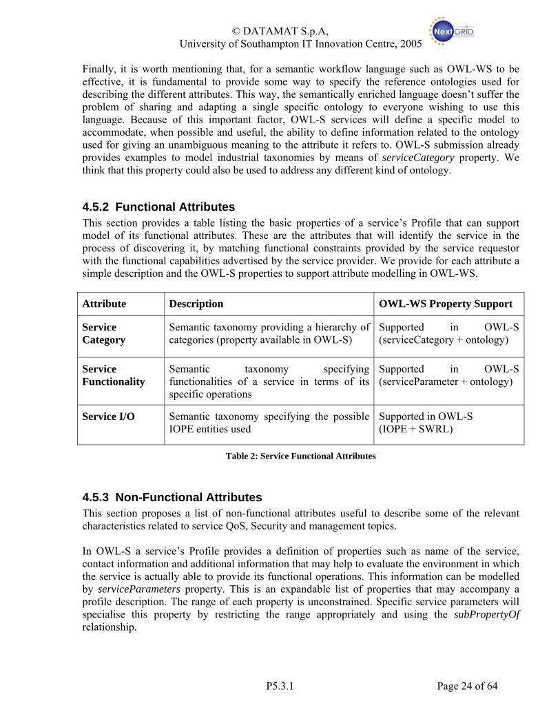
4.5.2 Functional Attributes This section provides a table listing the basic properties of a service’s Profile that can support model of its functional attributes. These are the attributes that will identify the service in the process of discovering it, by matching functional constraints provided by the service requestor with the functional capabilities advertised by the service provider. We provide for each attribute a simple description and the OWL-S properties to support attribute modelling in OWL-WS. Attribute Description OWL-WS Property Support
Service Category
Semantic taxonomy providing a hierarchy of categories (property available in OWL-S)
Supported in OWL-S (serviceCategory + ontology)
Service Functionality
Semantic taxonomy specifying functionalities of a service in terms of its specific operations
Supported in OWL-S (serviceParameter + ontology)
Service I/O Semantic taxonomy specifying the possible IOPE entities used
Supported in OWL-S (IOPE + SWRL)
Table 2: Service Functional Attributes
4.5.3 Non-Functional Attributes This section proposes a list of non-functional attributes useful to describe some of the relevant characteristics related to service QoS, Security and management topics. In OWL-S a service’s Profile provides a definition of properties such as name of the service, contact information and additional information that may help to evaluate the environment in which the service is actually able to provide its functional operations. This information can be modelled by serviceParameters property. This is an expandable list of properties that may accompany a profile description. The range of each property is unconstrained. Specific service parameters will specialise this property by restricting the range appropriately and using the subPropertyOf relationship.
P5.3.1 Page 24 of 64

© DATAMAT S.p.A, University of Southampton IT Innovation Centre, 2005
The following is a list of basic non-functional attributes we consider fundamental to provide additional information to a service description. We provide for each attribute a simple description and the OWL-S properties to support attribute modelling in OWL-WS.
Meta-data Type Description OWL-WS Property Support
Service Anatomy
Info providing name and text description. Info for telling if the service is self-sufficient or not and if it is abstract or not. Also, info may be provided for the business role and type of product of the service
Supported in OWL-S (serviceClassification, serviceName, etc…)
Service Management
Info specifically oriented to steer policy selection. Examples could be “co-allocation”, “local” (restricting search radius for discovery) and “scheduling strategy” (performance, market or trust-driven)
Supported in OWL-S (serviceParameter + ontology)
Service Reliability
Info specifying the types of fault mechanisms used for handling errors, exceptions and SLA failures. Examples could be “suspend”, “retry”, “rollback”, “checkpoint”, “alternative”
Supported in OWL-S (serviceParameter + ontology)
Service QoS Some info specifying the level of quality the service can achieve or require. Examples could be time, cost restrictions, etc…
Supported in OWL-S (serviceParameter + ontology)
Service Security
Taxonomy for specifying the security protocols accepted, the needed credentials and the security breach management protocols.
Supported in OWL-S (serviceParameter + ontology)
Table 3: Service Non-functional Attributes
Several of these “non-functional” aspects are related to the terms that should appear in Service Level Agreements. At this stage, it is assumed that OWL-WS may be used directly in SLA as a representation for some of these criteria (where process-oriented), and that in other cases the SLA representation can be derived from the OWL-WS Profiles or vice versa, as necessary. This will be explored further with NextGRID WP3 in the next project period.
P5.3.1 Page 25 of 64
© DATAMAT S.p.A, University of Southampton IT Innovation Centre, 2005
5 Workflow Management Model and Samples In order to validate our workflow language and model we define a basic User-Provider management model to be applied both for application and policy definition and usage. We then provide evidence of how OWL-WS model can be used to represent and manage typical use cases in the User-Provider model, also introducing basic OWL-WS management operation. We finally provide Profile samples for simple application and policy examples.
5.1 User-Provider Management Model We define a simple User-Provider model specifying actions for the two main roles. A User must be able to:
• Specify both services instances that are already known service implementations, and abstract services, that are functionality expressed by means of semantic information (e.g. standard service name).
• Compose Services in complex Workflow.
• Reuse previously defined Workflows and compose them in turn. A service Provider must be able to:
• Publish Services providing information on service discovery and execution (that is semantic, functional and implementation information)
• Publish workflows providing information on workflow discovery and execution. It is worth noticing that these roles do not necessarily represent interaction between application end-user and application service provider but are really actors performing specific functions. For instance, a user building a workflow and storing it for further usage is acting the role of Provider. Also, a Grid service administrator publishing policies to be used as evaluation mechanisms in the Workflow Enactment (see section 6) plays the Service Provider role, with an Enactment Engine playing the User role.
5.1.1 Workflows representation in User-Provider scenarios Several scenarios can be derived from the interaction between User and Provider roles according to their enabled actions. A User that only knows about the functionality that he wants to apply but not the service implementing them, can specify an Abstract Workflow that is composed by, for instance, two tasks A and B (see Figure 11). User can provide functional and non-functional requirements for the overall workflow, in Profile AB, and for the single tasks, in Profile A and B. It should be noted that information related to the data and control flow structure of the workflow, that are also provided by the user, are contained in the Composite Process AB
P5.3.1 Page 26 of 64

© DATAMAT S.p.A, University of Southampton IT Innovation Centre, 2005
xx
yy
zz
Task ATask A
Task BTask BQuery Profile A
Query Profile B
Composite Process AB
Abstract Process A
Abstract Process B
Service ABProfile AB
User provided informationUser provided information
OWLOWL--WS support informationWS support information
xx
yy
zz
Task ATask A
Task BTask B
xx
yy
zz
Task ATask A
Task BTask BQuery Profile A
Query Profile B
Composite Process AB
Abstract Process A
Abstract Process B
Service ABProfile AB
User provided informationUser provided information
OWLOWL--WS support informationWS support information Figure 11: User Defined Abstract Workflow
Figure 12 shows a case in which the user already knows the instances implementing the services he is composing and want to use these instances for modelling a complex concrete workflow. In this case user does not need to provide service constraints, instead it provides capability information on the overall service he is composing. As already discussed, Grounding A’ and B’ could be related to different services instances. It is worth noticing that in this case, that is when a Concrete Workflow is composed, user does not provide information for each single component but global capabilities should provide enough information to describe features of the workflows. Moreover, single components are only considered as part of the global workflow and cannot be addressed here as single elements, as for instance in case each single service is published on its own.
User Provided Information
OWL-WS Support information
Process A’ Grounding A’
Process B’ Grounding B’
x
Service A
y
z
Service B
Composite Process AB
Service ABProfile AB
Grounding AB
Provider Provided Information
User Provided Information
OWL-WS Support information
Process A’ Grounding A’
Process B’ Grounding B’
x
Service A
y
z
Service B
Composite Process AB
Service ABProfile AB
Grounding AB
Provider Provided Information
Figure 12: User Defined Concrete Workflow
Figure 13 shows how a Service Provider can use OWL-WS for modelling two services A’ and B’ that need to be published. Practically, information that can be useful for service discovery is mainly contained in the Service Profile while information needed for service execution is contained in the Service Grounding. Service Process contains more detailed information on service
P5.3.1 Page 27 of 64
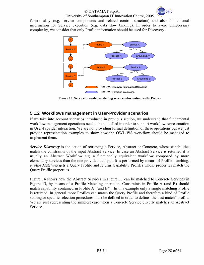
© DATAMAT S.p.A, University of Southampton IT Innovation Centre, 2005
functionality (e.g. service components and related control structure) and also fundamental information for Service execution (e.g. data flow binding). In order to avoid unnecessary complexity, we consider that only Profile information should be used for Discovery.
OWL-WS Discovery Information (Capability)
OWL-WS Execution information
Profile A’ Service A’
Process A’ Grounding A’
Profile B’ Service B’
Process B’ Grounding B’
x
y
Service A’
y
z
Service B’
OWL-WS Discovery Information (Capability)
OWL-WS Execution information
Profile A’ Service A’
Process A’ Grounding A’
Profile B’ Service B’
Process B’ Grounding B’
x
y
Service A’
y
z
Service B’
Figure 13: Service Provider modelling service information with OWL-S
5.1.2 Workflows management in User-Provider scenarios If we take into account scenarios introduced in previous section, we understand that fundamental workflow management operations need to be modelled in order to support workflow representation in User-Provider interaction. We are not providing formal definition of these operations but we just provide representation examples to show how the OWL-WS workflow should be managed to implement them. Service Discovery is the action of retrieving a Service, Abstract or Concrete, whose capabilities match the constraints of the input Abstract Service. In case an Abstract Service is returned it is usually an Abstract Workflow e.g. a functionally equivalent workflow composed by more elementary services than the one provided as input. It is performed by means of Profile matching. Profile Matching gets a Query Profile and returns Capability Profiles whose properties match the Query Profile properties. Figure 14 shows how the Abstract Services in Figure 11 can be matched to Concrete Services in Figure 13, by means of a Profile Matching operation. Constraints in Profile A (and B) should match capability contained in Profile A’ (and B’). In this example only a single matching Profile is returned. In general more Profiles can match the Query Profile and therefore a kind of Profile scoring or specific selection procedures must be defined in order to define “the best match” profile. We are just representing the simplest case when a Concrete Service directly matches an Abstract Service.
P5.3.1 Page 28 of 64
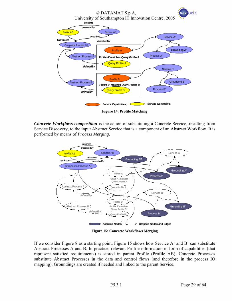
© DATAMAT S.p.A, University of Southampton IT Innovation Centre, 2005
Query Profile A
Query Profile B
Composite Process AB
Abstract Process A
Abstract Process B
Service ABProfile AB
definedBy
definedBy
describes
describedByhasProcess
presents
presentedBy
Profile A’
Service A’
Process A’
Grounding A’
Profile B’
Service B’
Process B’
Grounding B’
Profile A’ matches Query Profile A
Profile B’ matches Query Profile B
Service ConstraintsService Capabilities,
Query Profile A
Query Profile B
Composite Process AB
Abstract Process A
Abstract Process B
Service ABProfile AB
definedBy
definedBy
describes
describedByhasProcess
presents
presentedBy
Profile A’
Service A’
Process A’
Grounding A’
Profile B’
Service B’
Process B’
Grounding B’
Profile A’ matches Query Profile A
Profile B’ matches Query Profile B
Service ConstraintsService Capabilities, Figure 14: Profile Matching
Concrete Workflows composition is the action of substituting a Concrete Service, resulting from Service Discovery, to the input Abstract Service that is a component of an Abstract Workflow. It is performed by means of Process Merging.
Query Profile A
Query Profile B
Composite Process AB
Abstract Process A
Abstract Process B
Service ABProfile AB
definedBy
definedBy
describesdescribedByhasProcess
presentspresentedBy
Profile A’
Service A’
Process A’
Grounding A’
Profile B’
Service B’
Process B’
Grounding B’
Profile A’ matches Query Profile A
Profile B’ matchesQuery Profile B
Dropped Nodes and EdgesAcquired Nodes,
Grounding AB
Figure 15: Concrete Workflows Merging
If we consider Figure 8 as a starting point, Figure 15 shows how Service A’ and B’ can substitute Abstract Processes A and B. In practice, relevant Profile information in form of capabilities (that represent satisfied requirements) is stored in parent Profile (Profile AB). Concrete Processes substitute Abstract Processes in the data and control flows (and therefore in the process IO mapping). Groundings are created if needed and linked to the parent Service.
P5.3.1 Page 29 of 64

© DATAMAT S.p.A, University of Southampton IT Innovation Centre, 2005
Abstract Workflow composition is the action of substituting an Abstract Service, resulting from Service Discovery, to the Abstract Service provided as input for the matching. The input Abstract Service is a component of an Abstract Workflow. This operation is performed by means of Profile Merging. An Abstract Workflow is returned by Service Discovery when, for instance, an Abstract Service representing a Bind Policy (see section 5.3), can be represented with an Abstract Workflow whose components are still Abstract Services, representing simpler Policies. Concrete Services implementing the workflow components could depend on different underlying Grid infrastructure. Profile Merging is performed substituting the Profile of the input Abstract Service, containing constraints information, with the Capability Profile of the Abstract Service/Workflow that matches the Query. In this case, Workflow Composition maintains more information than for the concrete workflows composition. This is because we still have an Abstract Workflow that we may want to be resolved into a Concrete one and therefore we want to save the maximum of information that is provided.
Query Profile B
Composite Process AB
Abstract Process A
Abstract Process B
Service ABProfile ABdescribes
describedByhasProcess
presentspresentedBy
Service A’
Abstract Process C
Query Profile C
Profile B’
Service B’
Profile B’ matchesQuery Profile B
Query Profile A
Profile A’
Profile A’ matchesQuery Profile A
Composite Process DE
Abstract Process D
Query Profile D
Abstract Process E
Query Profile E
hasProfile
hasProfile
Composed Query Profiles
Query Profile B
Composite Process AB
Abstract Process A
Abstract Process B
Service ABProfile ABdescribes
describedByhasProcess
presentspresentedBy
Service A’
Abstract Process C
Query Profile C
Profile B’
Service B’
Profile B’ matchesQuery Profile B
Query Profile A
Profile A’
Profile A’ matchesQuery Profile A
Composite Process DE
Abstract Process D
Query Profile D
Abstract Process E
Query Profile E
hasProfile
hasProfile
Composed Query Profiles Figure 16: Abstract Workflows Composition
5.2 Simple User Application Sample In this section, we present a sample application workflow to describe capabilities and mechanisms used in OWL-WS model to represent and compose user application services and workflows. Information is related to explain how services can be composed, how services should be described, where IOPE information is stored and how to use it. We consider a simple workflow made up of a sequence of two abstract services with input/output data passed by between them. The workflow has a single initial input, denoted X and provided by the user that is used to feed Task A. Such task will then process the input according to its
P5.3.1 Page 30 of 64

© DATAMAT S.p.A, University of Southampton IT Innovation Centre, 2005
functionalities and output data, here denoted Y. Finally, Task B will use such input to produce the final output, denoted Z.
Task A Task Bx y zAB
Task A Task Bx y zAB
Figure 17: A sample application workflow
This simple example is sufficient, as it can describe all the concepts relevant to the description of an application workflow in OWL-WS model. These are descriptions of control and data flow; definition of input, output, preconditions and effects for each task; semantic description that has to be supported for allowing a flexible and abstract specification of an application workflow, its components and the user requirements. By using semantic keywords for workflow description and by integrating it natively into the workflow description language we enable the user to create and describe abstract workflows in a more natural and powerful way. The same semantic description will be used to provide powerful and flexible discovery and selection of services so to enrich the dynamic and adaptive capabilities of the workflow enactment process.
Profile of User-Workflow AB: P(AB)
Profile of Task A: P(A)Service Anatomy•Name: TaskA•Description: do task A•Structure: simple•Nature: abstract
Profile of Task B: P(B)
Service IOPE•DataOnt: someOntology•hasInput: X(inputType: someTypeX)
•hasOutput: Y(inputType: someTypeY)
Service Functionality•FuncOnt: #someURI•Function: someFuncA•Interactive: FALSE
Service Anatomy•Name: TaskB•Description: do task B•Structure: simple•Nature: abstract
Service IOPE•DataOnt: someOntology•hasInput: Y(inputType: someTypeY)
•hasOutput: Z(inputType: someTypeZ)
Service Functionality•FuncOnt: #someURI•Function: someFuncB•Interactive: TRUE
Service Anatomy•Name: TaskAB•Description: compose A & B•Structure: complex•Nature: abstract
Service IOPE•DataOnt: someOntology•hasInput: X(inputType: someTypeX)
•hasOutput: Z(inputType: someTypeZ)
Service Functionality•FuncOnt: null•Function: SeqComp(A, B)
Service Mngmnt•Domain: TrustedVOs•Strategy: performance•Reserve: FALSE
Service Reliability•SLAfail: migrate•Error/Exception: retry
Service QoS•CostLimit: -1•DelivTime: <15mins•Throughput: -1
Service Category•Name:
ApplicationSampleTaskA•Code: #AST1•Taxonomy: ASTaxonomy•Value: Task A
Service Category•Name:
ApplicationSampleTaskB•Code: #AST2•Taxonomy:ASTaxonomy•Value: Task B
Figure 18: Sample Profiles describing AB Workflow
Figure 18 shows Profile samples related to the overall AB workflow and to the two composing tasks A and B. An end user could have created these profiles with specific workflow editing tools capable of modelling, describing and annotating a workflow. Properties represented in these samples are significant examples of functional and non-functional attributes described in section 4.5. For instance, we defined example Service QoS parameters in the AB Profile to model Service QoS constraints concerning the overall workflow.
P5.3.1 Page 31 of 64
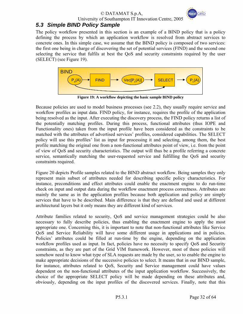
© DATAMAT S.p.A, University of Southampton IT Innovation Centre, 2005
5.3 Simple BIND Policy Sample The policy workflow presented in this section is an example of a BIND policy that is a policy defining the process by which an application workflow is resolved from abstract services to concrete ones. In this simple case, we assume that the BIND policy is composed of two services: the first one being in charge of discovering the set of potential services (FIND) and the second one selecting the service that fulfils at best the QoS and security constraints required by the user (SELECT) (see Figure 19).
FINDPa(A) Vec[Pc(A)] SELECT Pc(A)
BINDFINDPa(A) Vec[Pc(A)] SELECT Pc(A)FINDPa(A) Vec[Pc(A)] SELECT Pc(A)FINDPa(A) Vec[Pc(A)] SELECT Pc(A)
BIND
Figure 19: A workflow depicting the basic sample BIND policy
Because policies are used to model business processes (see 2.2), they usually require service and workflow profiles as input data. FIND policy, for instance, requires the profile of the application being resolved as the input. After executing the discovery process, the FIND policy returns a list of the potentially matching profiles. During this process, functional attributes (thus IOPE and Functionality ones) taken from the input profile have been considered as the constraints to be matched with the attributes of advertised services’ profiles, considered capabilities. The SELECT policy will use this profiles’ list as input for processing it and selecting, among them, the best profile matching the original one from a non-functional attributes point of view, i.e. from the point of view of QoS and security characteristics. The output will thus be a profile referring a concrete service, semantically matching the user-requested service and fulfilling the QoS and security constraints required. Figure 20 depicts Profile samples related to the BIND abstract workflow. Being samples they only represent main subset of attributes needed for describing specific policy characteristics. For instance, preconditions and effect attributes could enable the enactment engine to do run-time check on input and output data during the workflow enactment process correctness. Attributes are mainly the same as in the application profiles because both application and policy are simply services that have to be described. Main difference is that they are defined and used at different architectural layers but it only means they are different kind of services. Attribute families related to security, QoS and service management strategies could be also necessary to fully describe policies, thus enabling the enactment engine to apply the most appropriate one. Concerning this, it is important to note that non-functional attributes like Service QoS and Service Reliability will have some different usage in applications and in policies. Policies’ attributes could be filled at run-time by the engine, depending on the application workflow profiles used as input. In fact, policies have no necessity to specify QoS and Security constraints, as they are part of the Grid VIM framework. However, most of these policies will somehow need to know what type of SLA requests are made by the user, so to enable the engine to make appropriate decisions of the successive policies to select. It means that in our BIND sample, for instance, attributes related to QoS, Security and Service management could have values dependent on the non-functional attributes of the input application workflow. Successively, the choice of the appropriate SELECT policy will be made depending on these attributes and, obviously, depending on the input profiles of the discovered services. Finally, note that this
P5.3.1 Page 32 of 64

© DATAMAT S.p.A, University of Southampton IT Innovation Centre, 2005
concept also applies to possible required preconditions and effects of policies (think of a user workflow requiring a resolution without passing through intermediate abstract sub-workflows for instance).
Profile of BIND
Profile of SELECT
Service Anatomy•Name: SELECT•Description: select•Structure: simple•Nature: abstract
Profile of FIND
Service IOPE•DataOnt: NextGRID VM•hasInput: profile[]inputType: profile•hasOutput: profile(OutputType: profile)•Precond/Effect: null/ profile is concrete•Sync: TRUE
Service Functionality•FuncOnt: NextGRID VM•Function: SELECT(profile[])•Interactive: FALSE
Service Anatomy•Name: FIND•Description: Find•Structure: simple•Nature: abstract
Service IOPE•DataOnt: NextGRID VM•hasInput: profile(InputType: profile)•hasOutput: profile[](OutputType: profile)•Precond/Effect: null/null•Sync: TRUE
Service Anatomy•Name: BIND•Description: Bind a profile•Structure: complex•Nature: abstract
Service IOPE•DataOnt: NextGRID VM•InputType: profile•OutputType: profile•Precond/Effect: profile is abstract/ profile is concrete•Sync: TRUE
Service Functionality•FuncOnt: NextGRID VIM•Function: BIND(profile)•Interactive: FALSE
Service Mngmnt•Domain: ?•Strategy: ?•Reserve: ?
Service Reliability•SLAfail: ?•Error/Exception: ?
Service QoS•CostLimit: ?•DelivTime: ?•Throughput: ?•Responsivness: ?
Service Functionality•FuncOnt: NextGRID VM•Function: FIND(profile)•Interactive: FALSE
Service Category•Name:
BindServices•Code: #BS•Taxonomy:NGTaxonomy•Value: Binding
Service Category•Name:
FindService•Code: #FS•Taxonomy:NGTaxonomy•Value: Discovery
Service Category•Name:
SelectService•Code: #SS•Taxonomy:NGTaxonomy•Value: Selection
Figure 20: Sample Profiles for BIND policy.
Just to make a point on the policy management context, note that such policy workflows are supposed to be stored into a policy repository and that their selection is done, based on different factors such as the underlying grid environment, the requirements given by the user on the submitted application workflow and the available policies from the Grid VIM. The idea is that guides for which policy to be used should be included in the application workflow otherwise the default evaluation policy are used (see also 6.2). Policy selection could be performed according to several options:
• The default policy could be Grid VIM specific and therefore it will contain information on where to query for policy component services (for example FIND and SELECT).
• The engine could fetch the policy at workflow compile time.
• Available policies could be applied according to user specification provided at workflow composition time.
Clearly specifying policy selection options and formally defining related attributes in both the application and the policy profiles is the main objective of the activity of next months.
P5.3.1 Page 33 of 64
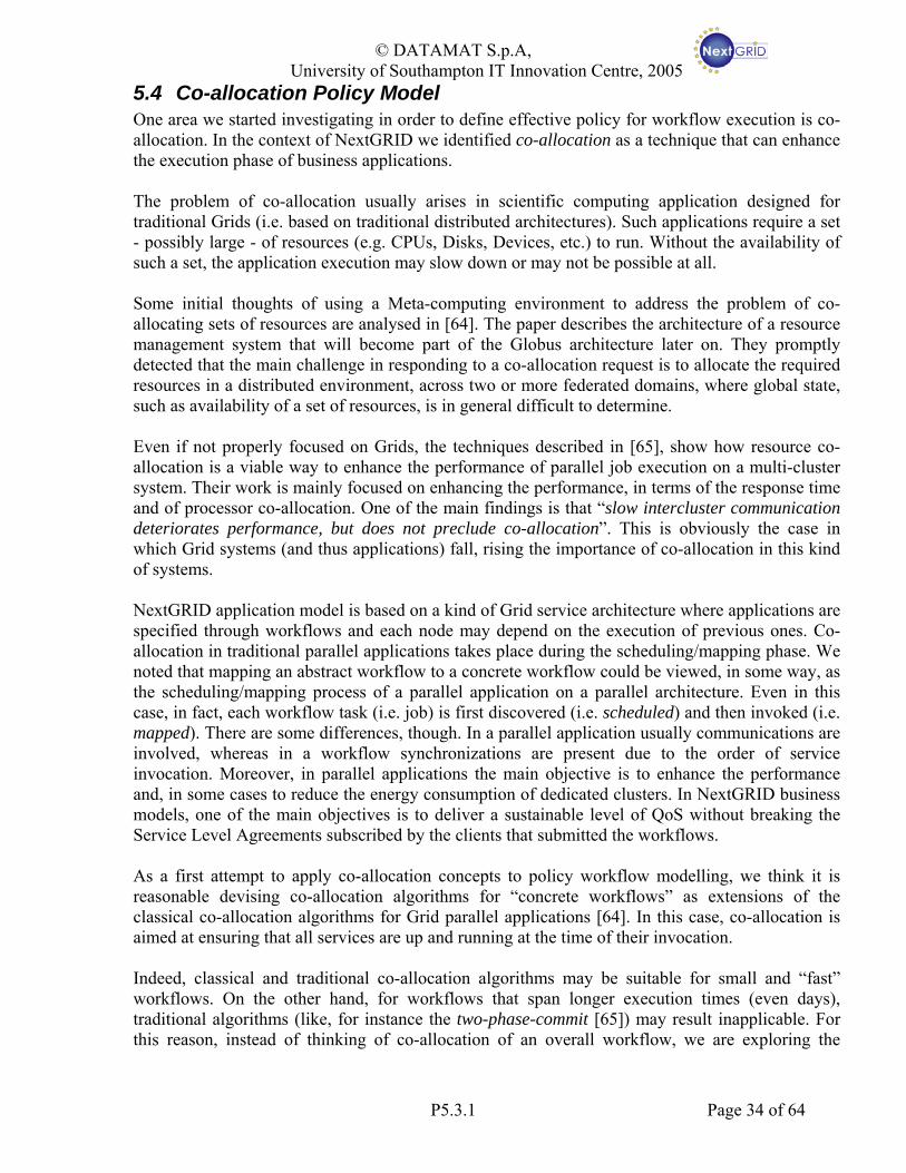
© DATAMAT S.p.A, University of Southampton IT Innovation Centre, 2005
5.4 Co-allocation Policy Model One area we started investigating in order to define effective policy for workflow execution is co-allocation. In the context of NextGRID we identified co-allocation as a technique that can enhance the execution phase of business applications. The problem of co-allocation usually arises in scientific computing application designed for traditional Grids (i.e. based on traditional distributed architectures). Such applications require a set - possibly large - of resources (e.g. CPUs, Disks, Devices, etc.) to run. Without the availability of such a set, the application execution may slow down or may not be possible at all. Some initial thoughts of using a Meta-computing environment to address the problem of co-allocating sets of resources are analysed in [64]. The paper describes the architecture of a resource management system that will become part of the Globus architecture later on. They promptly detected that the main challenge in responding to a co-allocation request is to allocate the required resources in a distributed environment, across two or more federated domains, where global state, such as availability of a set of resources, is in general difficult to determine. Even if not properly focused on Grids, the techniques described in [65], show how resource co-allocation is a viable way to enhance the performance of parallel job execution on a multi-cluster system. Their work is mainly focused on enhancing the performance, in terms of the response time and of processor co-allocation. One of the main findings is that “slow intercluster communication deteriorates performance, but does not preclude co-allocation”. This is obviously the case in which Grid systems (and thus applications) fall, rising the importance of co-allocation in this kind of systems. NextGRID application model is based on a kind of Grid service architecture where applications are specified through workflows and each node may depend on the execution of previous ones. Co-allocation in traditional parallel applications takes place during the scheduling/mapping phase. We noted that mapping an abstract workflow to a concrete workflow could be viewed, in some way, as the scheduling/mapping process of a parallel application on a parallel architecture. Even in this case, in fact, each workflow task (i.e. job) is first discovered (i.e. scheduled) and then invoked (i.e. mapped). There are some differences, though. In a parallel application usually communications are involved, whereas in a workflow synchronizations are present due to the order of service invocation. Moreover, in parallel applications the main objective is to enhance the performance and, in some cases to reduce the energy consumption of dedicated clusters. In NextGRID business models, one of the main objectives is to deliver a sustainable level of QoS without breaking the Service Level Agreements subscribed by the clients that submitted the workflows. As a first attempt to apply co-allocation concepts to policy workflow modelling, we think it is reasonable devising co-allocation algorithms for “concrete workflows” as extensions of the classical co-allocation algorithms for Grid parallel applications [64]. In this case, co-allocation is aimed at ensuring that all services are up and running at the time of their invocation. Indeed, classical and traditional co-allocation algorithms may be suitable for small and “fast” workflows. On the other hand, for workflows that span longer execution times (even days), traditional algorithms (like, for instance the two-phase-commit [65]) may result inapplicable. For this reason, instead of thinking of co-allocation of an overall workflow, we are exploring the
P5.3.1 Page 34 of 64

© DATAMAT S.p.A, University of Southampton IT Innovation Centre, 2005
possibility of defining effective policy to co-allocate subsets of such a workflow in order to ensure the contracted QoS parameters. The ability of the OWL-WS model to explicitly represent groups of services as workflows provides us means to handle this situation. In practice, each sub-workflow will have its overall Profile where requirements for co-allocation will be defined. From the application perspective, we could just define a “Co-allocation” property that can be set to the appropriate co-allocation algorithm that has to be applied during the workflow evaluation phase. A more accurate approach could be to define some kind of co-allocation metric(s), and related co-allocation property(ies) in the Profile, providing more detailed information for the Co-allocation Algorithms selection. This approach will be further investigated in next six months activity.
Figure 21: An example of conditional workflow. Here, the datum "Y" will be processed either by BT or BF
depending on the result of the evaluation of Y by Cond.
Let us suppose that the workflow partially depicted in Figure 21 is composed of several different long-running activities. Here, adopting a two-phase-commit protocol-based policy is clearly not correct since we cannot make any assumption on the availability of the allocated services due to the high dynamism of the Grid and to the long duration of each activity. Thus, to ensure the adherence to the performance agreements an evaluation policy to co-allocate and “anticipate” the execution of different branches of complex workflows should be applied. Recalling the figure above, Task BT will be executed only if Cond evaluates to True, Task BF will be executed otherwise. In this case, before knowing the outcome of the evaluation of Cond we could start executing both BT and BF and discard the wrong branch after the completion of Cond. Our next step will be formalizing this algorithm to form a Policy workflow also defining related profile properties. Experiments will be further planned in order to verify in which cases adopting Co-allocation Policy could provide benefits to application execution in the NextGRID environment. It is worth noticing that properties must be defined at both Policy and Application levels. The first are needed to provide description of capability of each co-allocation Policy available, the other ones to allow application designer to provide useful information to the Enactment Engine to select the most suitable co-allocation policy, if needed.
P5.3.1 Page 35 of 64

© DATAMAT S.p.A, University of Southampton IT Innovation Centre, 2005
6 Workflow Enactment
6.1 Enactment Model Overview As already discussed, the aim of NextGRID is to design and develop components that will define the “Next generation grid architecture” [1]. The target is to broaden the use of grids from the research-academic domain to include applications from the business world. So grid architecture should be such that will extend the support of application domains and adapt to different organisations in a secure and economically viable way. The workflow is one of the grid technologies that can provide this adaptability to distributed environments at runtime. In parallel with the development of a dynamic workflow representation (OWL-WS), we have been considering the design of a reference enactor implementation, to enable experiments on the use of the Grid VIM and dynamic workflow representations to combine applications and business policies. It is planned to base the reference implementation on Freefluo [64, 65], which is the workflow enactor used in conjunction with the Taverna user interface from myGrid.
Dynamic Service Discovery.
Service Binding and Access Model Registration.Workflow-based registry
Indexing of Services/Resourcesand Selection Mechanisms.Based on PageRank mechanism.
Semantic Workflow Representation.
Workflow EnactmentDynamically adaptive.
Dynamic Security and trust.
Dynamic Resource Allocation and Accounting
VO LifeCycle Support
WorkflowMapping Mechanismsbased on QoS estimates
Resource Brokering.
User designsApplication Workflow
AbstactWorkflowDescription
Services
Metacircular Evaluator
Services
PolicyRegistry
Apply
Evaluate
Figure 22: Enactment Model
Freefluo was chosen as the starting point because it was originally developed for myGrid [67] by IT Innovation as an open source project, so there are no IPR barriers to its use and exploitation in NextGRID. Furthermore, although used with Taverna to process the SCUFL language, Freefluo is a separate input-language independent enactor core that has been used with other workflow
P5.3.1 Page 36 of 64

© DATAMAT S.p.A, University of Southampton IT Innovation Centre, 2005
languages (including a version of WSFL with semantic annotation of data flows). It is designed to make it easy to apply the enactment core to different workflow languages, and so provides a useful platform for an experimental implementation of OWL-WS. The target of dynamic adaptation of workflow can be achieved by using the evaluate – apply [70] enactment method, borrowed from functional programming. This method will convert abstract workflows to concrete ones as well as executing them at runtime. The component of the enactment engine that will perform this process will be the workflow evaluator. The evaluation process differs amongst organisations so it should also dynamically be adapted to the organisation’s rules that define the evaluation policy. The enactment engine will use a policy registry to retrieve the evaluation policy of the abstract application workflow. Note that while application workflows typically provide abstract representations of the application services needed, policies will normally refer to registries and decision services (e.g. brokers, QoS estimators, etc). The rules defined in the policy will be described with a workflow using these services, so the evaluation of an application is also done by executing workflows. The enactor is thus formulated as a metacircular evaluator [70]. The abstract, user submitted, application workflow will be represented and referenced using the OWL-WS representation language. The evaluation is a recursive process that uses the semantic representation to resolve each abstract task in the user-designed workflow and replace it with a concrete sub-workflow. This translation will be performed according to the policy workflow, which will specify the evaluation strategy. The evaluator will use business process components as common services in its task to evaluate the workflow (see Figure 22). These components (along with other services) will be used at the “apply” phase, which occurs when a part of the workflow becomes concrete and executed by the enactor.
6.2 Role of the Workflow Representation Language The workflow representation language is an important component of the enactment model. The workflow language acts as a representation mechanism and a guide to resolve the workflow. The enactment process requires a workflow model from which the tasks (services) will be instantiated and enacted. So the language provides the interface specifications and other technical descriptions of the services. Evaluation procedure is modelled as a policy, an evaluation policy that is composed by workflow tasks. These tasks define the evaluation steps of the application workflow, which provide reference both to an abstract and to a concrete workflow. This reference is used at the “apply” phase to get and store enactment metadata (input/output types, running time, execution status etc). Also at the evaluation phase a reference of the workflow must be passed to the evaluator processor for resolving and replacing abstract or/and adding concrete service to the workflow representation document. This procedure and the role of the language will be further explained at a following paragraph. OWL-WS workflow description will include information to guide policy selection by specifying which policy to use and how to retrieve it from which organisation and its registries. This
P5.3.1 Page 37 of 64

© DATAMAT S.p.A, University of Southampton IT Innovation Centre, 2005
information will possibly be at the profile of the overall workflow providing being a kind of service group information. If this information is not present a default policy will be used. Finally OWL-WS will semantically describe a task and its interactions with the rest of the workflow. This description will provide the means of resolving the abstract service to one or more (sub-workflow) concrete service invocations. So it defines which available services are required in the evaluation process such as discovery, QoS, brokering etc and also provides “knowledge” discovery that is used to compose the functionality of one abstract service by using one or more other services, possibly abstract, that exists in the organisation.
6.3 Evaluation Method The type of evaluation that will be applied to branches of the workflow graph is “lazy”2. According to this, the part of the graph that is being executed is the only one that has been evaluated while the rest will be evaluated when it is about to run and thus discovery and binding information will have become available.
2 The design of the evaluation method that is used in this paragraph is based on some concepts that are also used in the lazy evaluation of lambda calculus [70]; but as this concept is applied to workflows and not to functions, it has several differences.
P5.3.1 Page 38 of 64

© DATAMAT S.p.A, University of Southampton IT Innovation Centre, 2005
AbstractTask A
AbstractTask B
EVAL
ConcreteTask D
ConcreteTask E
ConcreteTask F
AbstractTask C
APPLY
ConcreteTask F
AbstractTask B
EVAL
APPLY
AbstractTask B
AbstractTask D
AbstractTask C
AbstractTask D
AbstractTask C
AbstractTask D
ConcreteTask D
ConcreteTask E
ConcreteTask F
ConcreteTask H
ConcreteTask I
ConcreteTask J
Figure 23: Lazy Evaluation
This evaluation approach helps to achieve dynamic adaptation of workflow enactment. But postponing evaluation can cause problems in situations where concurrent branches should be enacted in parallel. For example let’s suppose that in Figure 23 tasks B and C must be executed concurrently for optimum performance; the evaluator will resolve first one of the two, let’s say B, and will postpone evaluation of the other for when its output is needed, i.e. when task D is applied. So by using this type of evaluation, tasks B and C are applied sequentially instead of in parallel. Also is likely that the evaluation policy specifies that multiple tasks should be evaluated concurrently. Policies can impose semantic constrains on the evaluation order of tasks. So this type of evaluation is not appropriate for such cases.
P5.3.1 Page 39 of 64

© DATAMAT S.p.A, University of Southampton IT Innovation Centre, 2005
AbstractTask A
AbstractTask B
EVAL
ConcreteTask D
ConcreteTask E
ConcreteTask F
APPLY
AbstractTask D
AbstractTask C
ConcreteTask G
ConcreteTask H
ConcreteTask K
ConcreteTask I
ConcreteTask J
Figure 24: Eager Evaluation
In these cases a more “eager” evaluation (see Figure 24) can be used inside the concurrent sub-workflows, to make sure that evaluation of both branches proceeds. Consequently the evaluator should dynamically change the evaluation method from “lazy” to “eager” and back again. This feature can also be described in the intermediate enactment language.
P5.3.1 Page 40 of 64

© DATAMAT S.p.A, University of Southampton IT Innovation Centre, 2005
Figure 25: Conceptual Design of the Evaluator
The components used in the ollowing steps:
• User submits an abstract workflow that has a semantic description of the functionality of his a
• ted at the right part o
• tor, which is marked as “Workflow Parser”, is a parser of the intermediate language, which supplies the evaluator with one of the tasks of Win while
6.4 The Metacircular Evaluator The following graph is a conceptual design of the metacircular evaluator.
X Y
Z
Task B
Task C
User Submitted Workflow Win
Win
Policy DrivenMetacircular
Evaluator(e.g. RecEval)
Wrest
If Processis Abstract
true
Abstract Bind(Discovery,
"Knowledge" Discovery, Selection)Input: Process Profile
Output: Workflow
Abstract Workflow
Parser
ConcreteTask 1
Wrest
Apply
Get sub-workflow
for each profile
V WTask A
ConcreteTask 2
in
merge
Sub-Workflow
False
evaluation process are explained with the f
pplication. This is passed to the Evaluator as input data using a reference (Win). References to workflows are enabled using the intermediate representation language.
The Metacircular Evaluator is a nested workflow. Its details are represenf the graph (see Figure 25). This nested-workflow task is an approach for a conceptual
design of the evaluation policy. Each evaluation policy gives an implementation for the workflow parser and binding.
The first process of the evalua
P5.3.1 Page 41 of 64

© DATAMAT S.p.A, University of Southampton IT Innovation Centre, 2005
p
• Parser selects more that one processes.
erwise, if it doesn’t have a service, i.e. can b
• ntic information. Typically will
r
• n
a As m ection 6.1), there are cases where “lazy” evaluation method is not the most ppropriate. This occurs when several tasks have to be evaluated and applied concurrently. In
eans one sub-workflow implements it together ith an iteration that feeds the rest of the workflow back to the evaluator’s input. Or the enactment
.5 Engine Requirements tment engine has little to do with the evaluation of the
ill be almost fully performed by the policy workflow.
cess! The traditional compile-run rchitecture of workflow engines will be replaced by a more dynamic and “lazy” procedure that
asses the rest (Wrest) to the merge process. Which task(s)? The answer depends on parser’s implementation and use of available services such as QoS. Application workflow may contain hints and guides for the evaluation process that can be used as parameters by the QoS services.
The processor that is marked as “for each profile” is used to iterate through multiple profiles when the
• If the output of the Parser is a concrete process profile then the task is merged with the rest of the workflow and is applied, i.e. executed. Oth
e bound to actual service invocations, the “Bind Sub-Workflow” process resolves it to a sub-workflow that contains selection and discovery service invocations. The binding process is defined by the policy and uses dynamic discovery [71], brokering metadata repositories and other components of the organisation. The output of this component is fed back to the parser to be parsed as it can also contain abstract processes.
The “knowledge” discovery defines the way that abstract processes can be converted to concrete ones according to the user’s hints and other semaeplace abstract service profiles with sets of possible concrete services (or further abstract
workflows) that are available and can provide the functionality that is described at the application workflow. The output of this component is fed back to the parser to be parsed.
The output of the evaluator is a set of tasks to be applied and the rest of the workflow to be evaluated; consequently the evaluator interprets workflows using the “lazy” evaluatiopproach.
entioned (saorder to support this, a processor that is iterating through all paths of the sub-workflow has been added to integrate into the evaluator the ability to evaluate eagerly some parts of the workflow. This can be achieved by iterating through the multiple tasks (of multiple branches) that the parser passes for evaluation as shown at the diagram. The outcome of the iteration is a new sub-workflow that is merged with the rest (Wrest) and is applied. The evaluation policy can be used iteratively; this mwengine can instantiate the first and the evaluator can add itself to the rest of the workflow every time, so one evaluator can be used for each sub-workflow of the application that is being evaluated. This is issue is currently under investigation.
6It is already clear that the role of the enacworkflow. The evaluation process wEnactment engine is responsible for enacting, i.e. instantiate and execute, the policy and application workflow, which will both be enacted by the engine. But the engine must support the runtime workflow evaluation proa
P5.3.1 Page 42 of 64

© DATAMAT S.p.A, University of Southampton IT Innovation Centre, 2005
can also be called “evaluate-apply”. According to this approach the evaluate phase will be used to instantiate only those processors that are bound to concrete services and not necessarily the whole workflow. The apply phase will follow to execute the processors. Then the engine state will swap to “evaluation” of concrete services produced at the apply phase and so on … (see Figure 26). If no concrete services are produced the enactment completes.
Figure 26: Engine Enactment State Diagram
The engine will use the OW rocessors and also to store service metadata and enactment status information.
the evaluation policy or use a default one. As lready mentioned OWL-WS will include guides to help the policy discovery and selection. The
L-WS descriptions to instantiate the p
The enactor will be configured to know where to findadefault policy seems, at this stage, the most likely place to encode this selection process. This will result to runtime policy selection according to application and/or Grid VIM indications. The new policy will replace the default and perform the further evaluation of the workflow.
Figure 27: Example of an extensible architecture: Freefluo architecture
P5.3.1 Page 43 of 64

© DATAMAT S.p.A, University of Southampton IT Innovation Centre, 2005
inally, another feature of the enactment engine is to have an extensible architecture. Engine
ent Engine
a parser of the OWL-WS language will be developed instead of the ScuflParser
• model will replace the myGrid one that will enable the use of policies
• lement the evaluation mechanism of policies will be developed
he en e additional features by extending its functionality
Fshould be able to support different workflow languages and different task types. For example different implementations of the language parser can satisfy the first requirement for extensibility. Although the representation and enactment of workflows will be performed using OWL-WS, development of new standards or change of requirements may enforce changes in the language and should be supported. Also ability to execute local tasks apart from web services can be supported by having different implementations of processor tasks. For these and the reasons explained at the beginning of this chapter, the extensible architecture of the Freefluo enactor, which is shown in the following diagram (Figure 27), will be used as a basis for the design and developments of the NextGRID workflow enactor engine.
order to implement the NextGRID workflow EnactmIn
•implementation, a NextGRID dataand other registry services, and a new task type, to impadditional to the existing ones.
gine core of Freefluo will support thTwhere it is needed. An example of such feature is the “evaluate-apply” states of the engine that were previously described. These extensions are currently at the design phase and will be presented and analysed at the P5.3.2 document, which is due to be delivered in PM18.
P5.3.1 Page 44 of 64

© DATAMAT S.p.A, University of Southampton IT Innovation Centre, 2005
7 Workflow Enactment Example
7.1 Use Case Scenario. This section provides a simple example of how the previously described application workflow would be enacted by the Workflow Engine, namely the metacircular evaluator. This workflow enactment sample will be based on the application workflow sample previously described in section 5.2 and on the BIND policy workflow sample described in section 5.3. Thus, our enactment sample will show how the application workflow submitted by the user will be evaluated by the engine, how input and output data will be managed, how policies will be applied and how profiles will be used to steer the enactment process. Moreover, this sample enactment will show how the workflow description, here represented graphically, will be managed and adapted during the whole process of discovery, selection and substitution of services carried-on inside the enactment. As a use case study, let’s consider the example of a user that composes a simple workflow with a sequence of numerical inputs, a processor that performs a numerical-A transformation and one that receives the output and performs a numerical-B transformation. The workflow would be similar to the one in Figure 29. Users can supply all the service information required for the invocation or just a description of their functionality (abstract services). The workflow engine should be able to evaluate the workflow, which means bind each abstract processor to a concrete one. So let’s assume that user provides abstract service descriptions in this example. Before the workflow can be evaluated, the evaluation policy has to be retrieved. Finally the services are enacted and the result is returned to the user (see Figure 28).
Figure 28: Use Case diagram
P5.3.1 Page 45 of 64

© DATAMAT S.p.A, University of Southampton IT Innovation Centre, 2005
7.2 Enactment of the Application The first step in workflow enactment is its submission from the user to the engine. Such submission is carried on by feeding the engine with the OWL-WS file that describes the application workflow the user wants to enact. Such file, written in XML, describes all the required information about a workflow’s characteristics: control and data flow constructs, IOPE information and semantic attributes. Figure 29 gives a graphical OWL-WS representation against the application workflow sample given previously.
Query Profile A
Query Profile B
Composite Process AB
Abstract Process A
Abstract Process B
Service ABProfile AB
User provided information,User provided information, OWL-WS internal informationOWL-WS internal information
x
y
z
Task A
Task B
Figure 29: OWL-WS graphical representation of the sample application workflow
As already explained, OWL-WS describes a workflow and its abstract services by the means of three entities: profiles, processes and groundings. Recall that groundings are available only when services have been concretised. In other cases only profiles and processes are available. This is the case of our initial application workflow sample enactment, in which the user specified only abstract services by the means of semantic information stored in the related profiles (AB, Query A and Query B in Figure 29). Figure 30 presents pieces of code taken from the OWL-WS file describing our application workflow sample. For the sake of simplicity part of the code has been folded and collapsed so to clearly highlight the basic OWL-WS process components. The complete OWL-WS code for the Application sample, also providing Profile properties details, can be found in Appendix I: OWL-WS Language Samples.
P5.3.1 Page 46 of 64

© DATAMAT S.p.A, University of Southampton IT Innovation Centre, 2005
Figure 30: Partially folded code written in OWL-WS describing the user sample application’s workflow
P5.3.1 Page 47 of 64

© DATAMAT S.p.A, University of Southampton IT Innovation Centre, 2005
The submission and initial enactment thus works as follows:
1. OWL-WS file representing workflow is sent to the engine. 2. The engine reads the file and specifically analyses the outermost profile, in our case the
Profile AB depicted in Figure 29. 3. Such profile gives the engine information on how to cope with the internal workflow
description: input data types and location are specified, control-flow constructs and abstract services are described.
4. The workflow enactment starts by choosing the evaluation policy as shown in phase 1 of Figure 31.
5. Then the workflow parser chooses which component of the Composite Process AB needs to be passed to the evaluator in this first iteration of the enactment process. Such decision depends on several factors: control-flow constructs specified in AB’s process description, attributes specified in AB’s profile (such as co allocation for instance) and others. In our simple example we assume that the parser uses a QoS prioritisation (e.g. critical path analysis) service to discover the order of evaluation. In this case the result is that B should be bound first, followed by A (see phase 2 Figure 31)
6. Then the discovery of the service takes place (see phase 3 Figure 31). Also knowledge discovery can be performed here. For example if the numbers were complex and the processor’s task was to add them, then the abstract add should be replaced by the add_imaginary and add_real ones.
7. Finally the service processor is instantiated and applied. The rest of the workflow is fed again to a parser and in similar manner the evaluate-apply steps of the second part of the workflow follow (see Figure 32).
WFin
PolicyDiscovery
Enactment Phase 1
WFin+Eval
Enactment Phase 2
QoS
WFHandler
WFrestWFfirst
WFfirst
Enactment Phase 3
Find
Select
Bservice
WFin+Eval
Parser
Figure 31: Workflow enactment as engine would perform. Each phase represent an engine “evaluation” phase
described in section 6.5
P5.3.1 Page 48 of 64
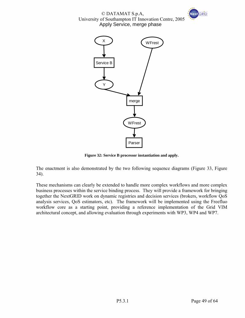
© DATAMAT S.p.A, University of Southampton IT Innovation Centre, 2005
X
Service B
Y
WFrest
merge
WFrest
Parser
Apply Service, merge phase
Figure 32: Service B processor instantiation and apply.
The enactment is also demonstrated by the two following sequence diagrams (Figure 33, Figure 34). These mechanisms can clearly be extended to handle more complex workflows and more complex business processes within the service binding process. They will provide a framework for bringing together the NextGRID work on dynamic registries and decision services (brokers, workflow QoS analysis services, QoS estimators, etc). The framework will be implemented using the Freefluo workflow core as a starting point, providing a reference implementation of the Grid VIM architectural concept, and allowing evaluation through experiments with WP3, WP4 and WP7.
P5.3.1 Page 49 of 64

© DATAMAT S.p.A, University of Southampton IT Innovation Centre, 2005
Figure 33: First part of enactment. Fetching the policy and iterate through the services of the application that
have to be evaluated
Figure 34: Second part. Discovery and execution of a resolved service is shown.
P5.3.1 Page 50 of 64

© DATAMAT S.p.A, University of Southampton IT Innovation Centre, 2005
8 Conclusion and Future Work In this document we presented a semantic workflow representation model and the OWL-WS language defined to apply this model. We also presented the concept view of the Workflow Engine that will take charge of enacting dynamic workflows by means of evaluation and binding mechanisms also represented as workflows. From the Workflow Representation Language perspective we plan to provide refinement and additional specification mainly establishing standard properties of service profiles. These properties should be agreed among all the involved tasks in NextGRID and therefore should derive from collaboration with:
• WP3, to explore the relationships between OWL-WS profiles and the terms in Service Level Agreements (SLA).
• WP4, for all that concerns UDAP model definition and in particular Grid resource description parameters – these should become meta-data elements in OWL-WS profiles.
• WP5, and specifically all tasks involved in definition of model for Service Discovery, Quality of Service and Negotiation/Brokering specifications.
• WP7 for all that concerns Application workflow requirements and Application level service description.
Properties describing Grid services at both application and business process service should be selected and agreed among all the tasks, each one according to specific needs. Understanding the role of the selected properties as capability and constraint and as policy or application properties is part of the OWL-WS language definition. To this aim, we will also pay attention to standard ontology definition, e.g. DublinCore, Rosetta.net, NAICS, and evolving technology in related research area, e.g. management of constraint and capability in Web Services environment [72] and WS-Policy specification [73]. Role of Pre-Conditions and Effects to help in policy specification and selection should also be further investigated. We will also provide strong support to other tasks for using the language to define effective real binding (e.g. QoS algorithms defined by WP5.4). In practice, business processes investigated and defined by other tasks will be represented as workflow by means of OWL-WS. This collaborative activity will be at the same time the main goal of Language Representation task and a valuable input for standard properties definition. Collaboration with WP6 will be also needed to provide a Workflow (or Policy) Editor definition with knowledge of the underlying workflow model and specification of the language. The workflow model will be shared in order to provide advance features that will provide added value to the Editor. Language specification will be needed to allow Editor generating workflows expressed in OWL-WS in language. From the Workflow Enactment perspective, strong collaboration with language definition will continue in order to define effective evaluation policy to model dynamic workflow enactment.
P5.3.1 Page 51 of 64

© DATAMAT S.p.A, University of Southampton IT Innovation Centre, 2005
The main objective will be providing integration to the overall workflow architectural framework. It means effectively defining application and policy workflows represented in OWL-WS, likely using WP6 defined Workflow Editor. Policy will be stored as part of the Grid Virtual Infrastructure Model, Applications will be the input and test case for the overall framework. A communication protocol, based on OWL-WS, between the Editor and the Engine will be defined therefore allowing Workflow Application defined in the Client Environment to be executed on the Grid by means of the Workflow Enactment Engine. From a wider perspective, we will also establish collaboration with WP2 in order to investigate how activity on OWL-WS can be directed towards influencing standardization efforts in both Semantic Web and Web Service areas. First objectives will be evaluating effectiveness of participation and collaboration with relevant working groups, like for instance GGF Semantic Grid Research Group and/or W3C Semantic Web Service Interest Group, and definition of a standardization effort plan for NextGRID in the semantic service area. Dissemination of these first results on workflow activity will be also provided starting from the IEEE sponsored e-Science 2005 conference in Melbourne in Dec’05 where OWL-WS model and language and integration of the Workflow Enactment Model in NextGRID infrastructure will be presented [77].
P5.3.1 Page 52 of 64

© DATAMAT S.p.A, University of Southampton IT Innovation Centre, 2005
9 References 1. Dave Snelling, Malcolm Atkinson, Sven van den Berghe, Konstantinos Dolkas, Mark Gilbert,
Alastair Hume, Greg Kohring, Guy Lonsdale, Thomas Sandholm, Mike Surridge, Kostas Tserpes, NextGRID Architecture, January 17, 2005, http://www.nextgrid.org/download/publications/NextGRID_Conceptual_Architecture_V_1_5.pdf
2. Workflow Management Coalition, Terminology & Glossary, Document Number WFMC-TC-1011, Issues 3.0, February 1999, http://www.wfmc.org/standards/docs/TC-1011_term_glossary_v3.pdf
3. Treadwell, J. (ed.) Open Grid Services Architecture Glossary of Terms. Global Grid Forum OGSA-WG. GFD-I.044, January 2005, http://www.ggf.org/documents/GWD-I-E/GFD-I.044.pdf
4. David Snelling, Mike Fisher, Achim Basermann (eds), NextGRID Vision and Architecture White Paper.
5. Foster, I., Kishimoto, H.,. Savva, A., Berry, D., Djaoui, A., Grimshaw, A., Horn, B., Maciel, F., Siebenlist, F., Subramaniam, R., Treadwell, J., and Von Reich, J.: The Open Grid Services Architecture, Version 1.0. Global Grid Forum OGSA-WG. GFD-I.030, January 2005, http://www.ggf.org/documents/GWD-I-E/GFD-I.030.pdf.
6. FLE, NextGRID Project Output P1.4.1: Architecture Conceptualisation Report.
7. IT Innovation, NextGRID Deliverable D5.1: Grid Dynamics Report.
8. A. Arkin, S. Askary, B. Bloch et. al, WS-BPEL: Web Services Business Process Execution Language Version 2.0, OASIS Open, December 2004. This document is available at http://www.oasis-open.org/committees/download.php/10347/wsbpel-specification-draft-120204.htm
9. Tom Oinn, Matthew Addis, Justin Ferris, Darren Marvin, Martin Senger, Mark Greenwood, Tim Carver, Kevin Glover, Matthew R. Pocock, Anil Wipat and Peter Li. Taverna: A tool for the composition and enactment of bioinformatics workflows, Bioinformatics Journal 20(17) pp 3045-3054, 2004.
10. A. Turing, On Computable Numbers, With an Application to the Entscheidungsproblem, Proceedings of the London Mathematical Society, Series 2, Volume 42, 1936; reprinted in M. David (ed.), The Undecidable, Hewlett, NY: Raven Press, 1965
11. Barendregt and Henk, The lambda calculus, its syntax and semantics, North-Holland, 1984
12. C.A.R. Hoare, Communicating Sequential Processes, Prentice-Hall International, 1985
13. R. Milner, A Calculus of Communicating Systems, Springer Verlag, ISBN 0387102353
14. R. Milner, Communicating and Mobile Systems: the Pi-Calculus, Springer Verlag, ISBN 0521658691
15. D. Sangiorgi and D. Walker, The Pi-calculus: A Theory of Mobile Processes, Cambridge University Press, ISBN 0521781779
16. W.M.P Van Der Aalst, Pi Calculus Versus Petri Nets: Let Us Eat The Humble Pie Rather Than Inflate The Pi Hype, BPTrends, 3(5):1-11, May 2005
P5.3.1 Page 53 of 64

© DATAMAT S.p.A, University of Southampton IT Innovation Centre, 2005
17. H. Smith and P. Fingar, Workflow is Just a Pi Process, October 2003
18. C. Peltz, Web Services Orchestration and Choreography, p 46-52, IEEE Computer, October 2003
19. WfMC, XPDL: XML Process Definition Language, ver 1.06, June 2005. This document is available at http://www.wfmc.org/standards/docs/2005-06-13 xpdl 2.zip
20. B. Eisenberg, D. Nickull et. al, ebXML Technical Architecture Specification v1.04, February 2001. This document is available at http://www.ebxml.org/specs/ebTA.pdf
21. OASIS: Organization for the Advancement of Structured Information Standards, http://www.oasis-open.org/home/index.php
22. Satish Thatte (ed.), Business Process Execution Language for Web Services Version 1.1, May 2003, http://www-106.ibm.com/developerworks/webservices/library/ws-bpel/
23. XLANG, Satish Thatte, Autthor. Microsoft Corporation, 2001. This document is available at http://www.gotdotnet.com/team/xml_wsspecs/xlang-c/default.htm
24. WSFL 1.0, Frank Leymann, Editor. IBM, May 2001. This PDF document is available at http://www-3.ibm.com/software/solutions/webservices/pdf/WSFL.pdf
25. A. Arkin, BPML: Business Process Modeling Language, BPMI.org, November 2002, This document is available at http://www.bpmi.org/downloads/BPML1.0.zip
26. N. Kavantzas, D. Burdett and G. Ritzinger, WSCDL: Web Service Choreography Description Language, W3C, April 2004. This document is available at http://www.w3.org/TR/2004/WD-ws-cdl-10-20040427/
27. A. Arkin, S. Askary, S. Fordin et. Al, WSCI: Web Service Choreography Interface, ver. 1.0, The latest version is available at http://www.w3.org/TR/2002/NOTE-wsci-20020808
28. S. Weerawarana, R. Chinnici, M. Gudgin et. al, WSDL: Web Services Description Language Version 2.0 Part 1: Core Language, World Wide Web Consortium, August 2004. The latest version is available at http://www.w3.org/TR/wsdl20.
29. D. Box, D. Ehnebuske, G. Kakivaya, A. Layman, N. Mendelsohn, H. Frystyk Nielsen, S. Thatte, D. Winer, Editors., Simple Object Access Protocol (SOAP) 1.1, World Wide Web Consortium Note, 8 May 2000, http://www.w3.org/TR/2000/NOTE-SOAP-20000508/
30. Luc Clement, Andrew Hately, Claus von Riegen, Tony Rogers (Eds), UDDI Version 3.0.2 specification, OASIS, October 2004, http://www.oasis-open.org/committees/uddi-spec/doc/spec/v3/uddi-v3.0.2-20041019.htm
31. Jörg Desel , Wolfgang Reisig , Grzegorz Rozenberg (Eds.), Lectures on Concurrency and Petri Nets, Advances in Petri Nets, Lecture Notes in Computer Science, vol. 3098, Springer-Verlag, 2004.
32. Stephen A. White (Ed.), Business Process Modeling Notation (BPMN) Version 1.0, May 2004, http://www.bpmn.org/Documents/BPMN V1-0 May 3 2004.pdf
33. T. Gardner, UML modelling of automated business processes with a mapping to BPEL4WS. In First European Workshop on Object Orientation and Web Service (EOOWS), Darmstadt, Germany, 21 July 2003, http://www.cs.ucl.ac.uk/staff/g.piccinelli/eoows/documents/paper-gardner.pdf
P5.3.1 Page 54 of 64

© DATAMAT S.p.A, University of Southampton IT Innovation Centre, 2005
34. S. Pllana, T. Fahringer, J. Testori, S. Benkner, and I. Brandic. Towards an UML Based Graphical Representation of Grid Workow Applications. In The 2nd European Across Grids Conference, Nicosia, Cyprus, January 2004. Springer-Verlag, http://dps.uibk.ac.at/~pllana/publications/pftbb-axgrids04.pdf
35. J.Scicluna, C.Abela, M.Montebello,Visual Modelling of OWL-S Services, submitted at the IADIS International Conference WWW/Internet, Madrid Spain, October 2004, http://www.daml.org/services/owl-s/pub-archive/Visual-Modeling-of-OWL-S-Services.pdf
36. 4343D. Riehle and H. Zullighoven. Understanding and Using Patterns in Software Development. Theory and Practice of Object Systems, 2(1):3-13, 1996.
37. E. Gamma, R. Helm, R. Johnson, and J. Vlissides. Design Patterns: Elements of Reusable Object-Oriented Software. Addison-Wesley, Reading, Massachusetts, 1995.
38. M. Fowler. Analysis Patterns: Reusable Object Models. Addison-Wesley, Reading, Massachusetts, 1997.
39. W.M.P. van der Aalst, A.H.M. ter Hofstede, B. Kiepuszewski, and A.P. Barros, Workflow Patterns, Distributed and Parallel Databases, 14(3), pages 5-51, July 2003. http://is.tm.tue.nl/research/patterns/download/wfs-pat-2002.pdf
40. Jia Yu and Rajkumar Buyya, A Taxonomy of Workflow Management Systems for Grid Computing, Technical Report, GRIDS-TR-2005-1, Grid Computing and Distributed Systems Laboratory, University of Melbourne, Australia, March 10, 2005.
41. See the K-Wf grid Knowledge-based Workflow System for Grid Applications.See the project website at http://www.kwfgrid.net
42. Hoheisel, A., Der, U., Dynamic Workflows for Grid Applications. In: Proceedings of the Cracow Grid Workshop '03. Krakau, Polen, 2003, http://www.andreas-hoheisel.de/docs/Hoheisel_and_Der_2003_CGW03.pdf
43. David Martin (ed), OWL-S: Semantic Markup for Web Services, W3C Member submission, November 2004, http://www.w3.org/Submission/2004/SUBM-OWL-S-20041122/
44. T. Fahringer, S. Pllana, and A. Villazon, AGWL: Abstract Grid Workflow Language, Proceedings of the International Conference on Computational Science, Programming Paradigms for Grids and Metacomputing Systems, Krakow, Poland, June 2004. Springer-Verlag. http://dps.uibk.ac.at/projects/agwl/agwlpubs/AGWL-PPGaMS2004.pdf
45. Kaizar Amin1 and Gregor von Laszewski, GridAnt: A Grid Workflow System, Manual, February 2003, http://www-unix.globus.org/cog/projects/gridant/gridant-manual.pdf
46. See the Globus Toolkit website at http://www.globus.org/toolkit/
47. See the CoG Kit website at http://www.cogkit.org/
48. Gregor von Laszewski and Mike Hategan, Grid Worfklow: An Integrated Approach, draft of a proposal for a book chapter, http://www-unix.mcs.anl.gov/~laszewsk/papers/vonLaszewski-workflow-draft.pdf
49. Ewa Deelman, James Blythe, Yolanda Gil, and Carl Kesselman, Grid Resource Management, chapter Workflow Management in GriPhyN. Kluwer, 2003. Available from http://www.isi.edu/~deelman/Pegasus/grm_chapter.pdf
P5.3.1 Page 55 of 64
© DATAMAT S.p.A, University of Southampton IT Innovation Centre, 2005
50. Shalil Majithia, Matthew S. Shields, Ian J. Taylor, and Ian Wang, Triana: A Graphical Web Service Composition and Execution Toolkit, in Proceedings of the IEEE International Conference on Web Services (ICWS'04), pages 514-524. IEEE Computer Society, 2004. http://www.trianacode.org/papers/pdf/TrianaAHM03WS.pdf
51. Sulev Sild, Uko Maran, Mathilde Romberg, Bernd Schuller, Emilio Benfenati, OpenMolGRID: Using Automated Workflows in GRID Computing Environment. Proceedings of European Grid Conference, Amsterdam, The Netherlands, 2005, Springer, LNCS 3470, pages 464-473, http://www.fz-juelich.de/zam/vsgc/pub/sild-2005-OUA.pdf
52. Tim Berners-Lee, James Hendler, and Ora Lassila, The Semantic Web, Scientific American, 284(5):34-43, May 2001, http://www.cs.nyu.edu/rgrimm/teaching/readings/semantic-web.pdf
53. Resource Description Framework (RDF): Concepts and Abstract Syntax, W3C Recommendation 10 February 2004, http://www.w3.org/TR/2004/REC-rdf-concepts-20040210/
54. See Resource Description Framework website at http://www.w3.org/RDF/
55. Deborah L. McGuinness, Frank van Harmelen (eds), OWL Web Ontology Language Overview, W3C Recommendation, February 10, 2004, http://www.w3.org/TR/owl-features/
56. See the Semantic Web website at http://www.w3.org/2001/sw/
57. See OWL-S 1.1 Release website at http://www.daml.org/services/owl-s/1.1/
58. Web Service Modeling Ontology (WSMO) Submission, W3C Member Submission, April 2005, http://www.w3.org/Submission/2005/06/
59. See WSMO website at http://www.wsmo.org/index.html
60. R. Akkiraju, J. Farrell, J.Miller, M. Nagarajan, M. Schmidt, A. Sheth, K. Verma, "Web Service Semantics - WSDL-S, " A joint UGA-IBM Technical Note, version 1.0, April 18, 2005, http://lsdis.cs.uga.edu/library/download/WSDL-S-V1.pdf
61. Richard Hull, Jianwen Su, Tools for Design of Composite Web Services, Tutorial in SIGMOD 04, June 2004, http://www.cs.ucsb.edu/~su/tutorials/sigmod2004.html
62. Semantic Web Rule Language (SWRL), W3C Member Submission, May 2004, http://www.w3.org/Submission/2004/03/
63. NEC, NextGRID Project Output P7.2.1: Applications Requirements Report.
64. K. Czajkowski, I. Foster, N. Karonis, C. Kesselman, S. Martin, W. Smith, and S. Tuecke. A resource management architecture for metacomputing systems. In The 4th Workshop on Job Scheduling Strategies for Parallel Processing, pages 62–82. Springer-Verlag LNCS 1459, 1998.
65. Anca I. D. Bucur, Dick H. J. Epema. The Performance of Processor Co-Allocation in Multicluster Systems. CCGRID 2003, pages 302-309, 2003.
66. Butler W. Lampson, and Howard E. Stugis. Crash Recovery in a Distributed Data Storage System. June 1, 1979. Unpublished report Xerox Palo Alto Research Center.
67. Matthew Addis, Justin Ferris, Mark Greenwood, Darren Marvin, Peter Li, Tom Oinn and Anil Wipat Experiences with eScience workflow specification and enactment in bioinformatics, http://www.nesc.ac.uk/events/ahm2003/AHMCD/pdf/108.pdf
P5.3.1 Page 56 of 64

© DATAMAT S.p.A, University of Southampton IT Innovation Centre, 2005
68. Freefluo Enactor: http://freefluo.sourceforge.net/
69. Carole Goble, Chris Wroe, Robert Stevens and the myGrid consortium: The myGrid project: services, architecture and demonstrator. EPSRC e-Science Pilot Project myGrid. Available at http://www.mygrid.org.uk/
70. Structure And Interpretation of Computer Programs, Harold Abelson and Gerald Jay Sussman with Julie Sussman, 1996, The Massachusetts Institute of Technology
71. “Dynamic Distributed Registries and Protocol”, Peer Hasselmeyer, NextGRID WP5 Output of task 5.2.1: dynamic distributed registries, August 2005.
72. Program of W3C Workshop on Constraints and Capabilities for Web Services. At http://www.w3.org/2004/09/ws-cc-program - summary
73. Jeffrey Schlimmer (Editor), Web Services Policy Framework (WS-Policy), September 2004. Available at ftp://www6.software.ibm.com/software/developer/library/ws-policy.pdf
74. D. Martin et al, "Bringing semantics to Web Services: The OWL-S approach", in Proc. First Intern. Workshop on Semantic Web Services and Web Process Composition (SWSWPC 2004), July 6-9, 2004, San Diego, California, USA. (2004)
75. See OWL-S Editor web site at http://projects.semwebcentral.org/projects/owlseditor/
76. See Protégé Ontology Editor web site at http://protege.stanford.edu/
77. Stefano Beco, Barbara Cantalupo, Ludovico Giammarino, Mike Surridge and Nikolaos Matskanis. OWL-WS: A Workflow Ontology for Dynamic Grid Service Composition, accepted to the 1st IEEE International Conference on e-Science and Grid Computing, Dec. 5 - 8, 2005, Melbourne, Australia
P5.3.1 Page 57 of 64

© DATAMAT S.p.A, University of Southampton IT Innovation Centre, 2005
Appendix I: OWL-WS Language Samples In this section OWL-WS sample, related to the simple user application example introduced in section 5.2 are provided. Samples were produced by using OWL-S plugin [74, 75] for Protégé Ontology Editor [76]. We defined OWL-WS extension as new ontology elements in OWL-S Plugin. Two main restrictions apply to the generated samples:
• For sake of simplicity only main attributes have been defined in Service Profiles.
• Elements related to Services, Profiles and Processes are provided all together while according to OWL-S W3C submission they should be described and provided in different files (and spaces). This is due to the tool we used.
While Figure 18 hinted a high-level subdivision of a service’s properties into different sections, the same profiles are now presented in a more detailed way, so to depict more clearly the set of attributes effectively described in the coding example (see Figure 35). Attributes in bold can be found also in the following OWL-WS code sample.
Profile of User-Workflow AB: P(AB)
Profile of Task B: P(B)
Service Anatomy•Name: TaskB•Description: do task B•Structure: simple•Nature: abstract
Profile of Task A: P(A)Service IOPE•DataOnt: #someURI•hasInput: yB(InputType: someTypeY•hasOutput:zB (OutputType: someTypeZ)Precond/Effect: null/null•Sync: TRUE
Service Functionality•FuncOnt: #someURI•Function: someFuncB•Interactive: FALSE
Service Category•Name:
ApplicationSampleTaskA•Code: #AST1•Taxonomy: ASTaxonomy•Value: Task A
Service Anatomy•Name: TaskA•Description: do task A•Structure: simple•Nature: abstract
Service IOPE•DataOnt: #someURI•hasInput: xA(InputType: someTypeX•hasOutput:yA (OutputType: someTypeY)•Precond/Effect: null/null•Sync: TRUE
Service Functionality•FuncOnt: #someURI•Function: someFuncA•Interactive: TRUE
Service Anatomy•Name: TaskAB•Description: compose A and B•Structure: complex•Nature: abstract
Service Functionality•hasProcess:
CompositeProcessAB•FuncOnt: null•Function: SeqComp(A, B)•Interactive: TRUE
Service Mngmnt•Domain: Trusted VOs•Coallocation:TRUE•Strategy: performance•Reserve: FALSE
Service Reliability•SLAfail: migrate•Error/Exception: retry
Service QoS•CostLimit: -1•DelivTime: <15mins•Throughput: -1
Service IOPE•DataOnt: #someURI•hasInput: x (InputType: someTypeX)•hasOutput: z(OutputType: someTypeZ)•Precond/Effect: null/null•Sync: TRUE
Service Category•Name:
ApplicationSampleTaskB•Code: #AST2•Taxonomy:ASTaxonomy•Value: Task B
Figure 35: Detailed sample profile with attributes from OWL-WS code
Figure 36, provided in the following pages, shows the OWL-WS code related to this user application sample. In this code all the basic entities, categories and attributes introduced in this document are depicted.
P5.3.1 Page 58 of 64

© DATAMAT S.p.A, University of Southampton IT Innovation Centre, 2005
P5.3.1 Page 59 of 64

© DATAMAT S.p.A, University of Southampton IT Innovation Centre, 2005
P5.3.1 Page 60 of 64
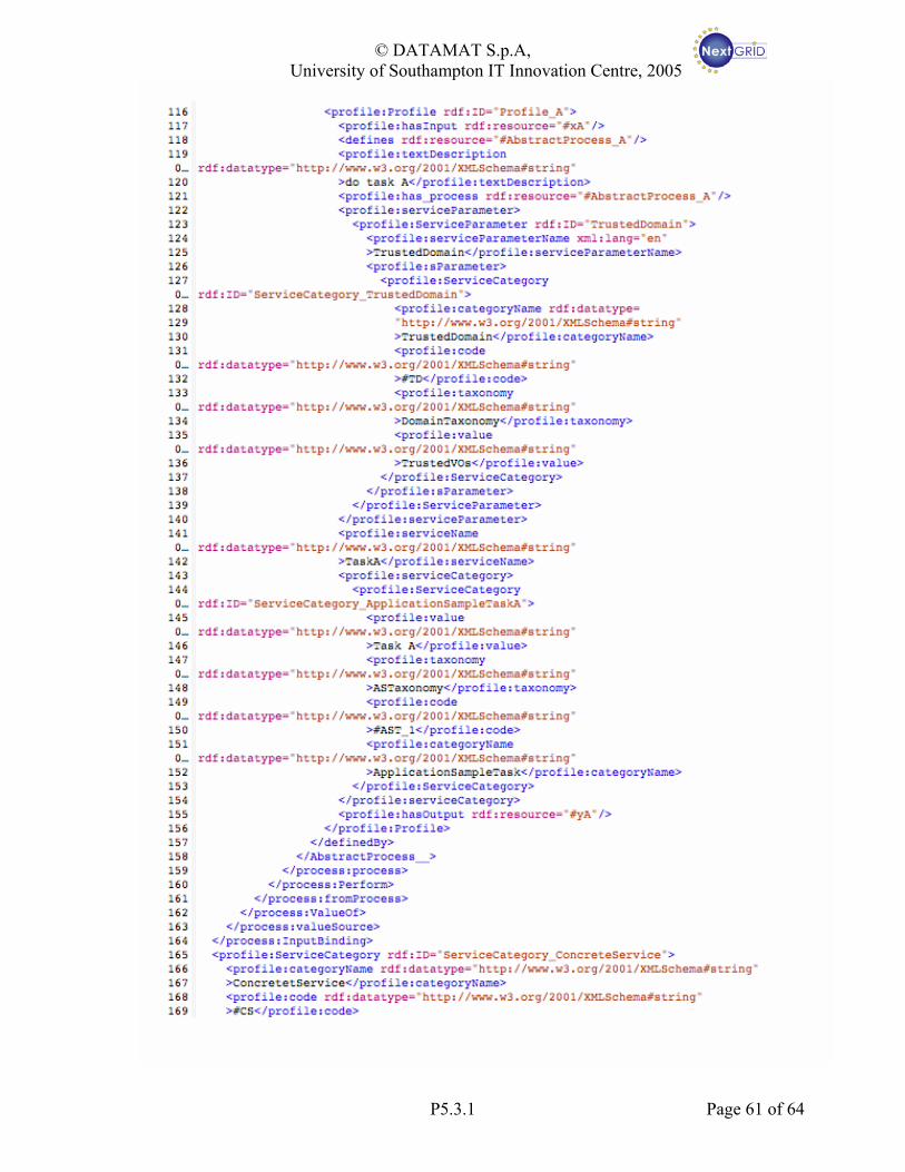
© DATAMAT S.p.A, University of Southampton IT Innovation Centre, 2005
P5.3.1 Page 61 of 64

© DATAMAT S.p.A, University of Southampton IT Innovation Centre, 2005
P5.3.1 Page 62 of 64

© DATAMAT S.p.A, University of Southampton IT Innovation Centre, 2005
P5.3.1 Page 63 of 64

© DATAMAT S.p.A, University of Southampton IT Innovation Centre, 2005
Figure 36: User sample application’s OWL-WS code
It is worth noticing that, for the sake of completeness, some additional taxonomy has been introduced so to give an idea of how semantic of some attributes should be coped with. Thus, for instance, the “Domain” and “Strategy” attributes will have their own taxonomy defining all the possible semantic values for which an unambiguous definition should be given (as for every ontology).
P5.3.1 Page 64 of 64