Semantic based model of Conceptual Work Products for ...
11
Semantic based model of Conceptual Work Products for formal verification of complex interactive systems Mohcine Madkour 1* , Keith Butler 2 , Eric Mercer 3 , Ali Bahrami 4 , Cui Tao 1 1 The University of Texas Health Science Center at Houston, School of Biomedical Informatics, 7000 Fannin St Suite 600, Houston, TX 77030 2 University of Washington, Department of Human Centered Design and Engineering Box 352315, Sieg Hall, Room 208 Seattle, WA 98195 3 Brigham Young University Computer Science Department, 3334 TMCB PO Box 26576 Provo, UT 84602-6576 4 Medico System Inc. 10900 NE 8th Street Suite 900 Bellevue, WA 98004 * Corresponding author, email: [email protected], phone: (+1) 281-652-7118 Abstract - Many clinical workflows depend on interactive computer systems for highly technical, conceptual work products, such as diagnoses, treatment plans, care coordination, and case management. We describe an automatic logic reasoner to verify objective specifications for these highly technical, but abstract, work products that are essential to care. The conceptual work products specifications serve as a fundamental output requirement, which must be clearly stated, correct and solvable. There is strategic importance for such specifications because, in turn, they enable system model checking to verify that machine functions taken with user procedures are actually able to achieve these abstract products. We chose case management of Multiple Sclerosis (MS) outpatients as our use case for its challenging complexity. As a first step, we illustrate how graphical class and state diagrams from UML can be developed and critiqued with subject matter experts to serve as specifications of the conceptual work product of case management. A key feature is that the specification must be declarative and thus independent of any process or technology. UML can represent the needed static and dynamic abstractions but it also allows inconsistent, unsolvable models. Our Work Domain Ontology with tools from Semantic Web is needed to translate UML class and state diagrams for verification of solvability with automatic reasoning. The solvable model will then be ready for subsequent use with model checking on the system of human procedures and machine functions. We used the expressive rule language SPARQL Inferencing Notation (SPIN) to develop formal representations of the UML class diagram, the state machine, and their interactions. Using SPIN, we proved the consistency of the interactions of static and dynamic concepts. We discuss how the new SPIN rule engine could be incorporated in the Object Management Group (OMG)’s Ontology Definition Metamodel (ODM). Index Terms - Keywords: Conceptual work product; UML Class diagram; UML State machine; Inconsistency Checking; Model Checking; RDF; OWL; SPARQL Inference Notation (SPIN). 1. Introduction Many critical systems require highly complex user interactions and a large number of cognitive tasks. These systems are common in clinical health care and also many other industries where the consequences of failure can be very expensive or risky to human safety. Formal verification through model checking could reduce or prevent system failures, but several technical obstacles must be solved first. We focus here on the abstract products of conceptual work that are foundational requirements that must be part of verification in a modern health care systems. Examples of such conceptual work products include diagnoses, medication reconciliation, treatment plans of orders, care coordination, case management, etc. There are several reasons why these conceptual work products are difficult for system developers. They are complex and abstract, with no required tangible manifestation until they are acted upon. They are often developed in an environment of distributed cognition, where no single agent possesses complete knowledge of their state. They are commonly carried out by multiple clinicians with information that must be integrated from computer systems and the physical environment. Despite their importance and technical content, conceptual work products in health care are often only vaguely defined. Software developers often try define them in terms of user procedures and software features that will be used to create them. This causes a logical problem: in order to serve as a verification criterion, the specification must be stated independently from the system needing verification, or it risks being a tautology instead of an evaluation. More generally, models of information systems that lack clear, yet consistent specifications for their work products are seriously incomplete. This gap forces developers to rely on intuition about this fundamental purpose of a system, even when the domains are highly technical and critical system failures can risk the health, safety or security of large groups of people. Declarative Specifications
Transcript of Semantic based model of Conceptual Work Products for ...

Semantic based model of Conceptual Work Products
for formal verification of complex interactive systems
Mohcine Madkour1*
, Keith Butler2, Eric Mercer
3, Ali Bahrami
4, Cui Tao
1
1 The University of Texas Health Science Center at Houston, School of Biomedical Informatics, 7000 Fannin St Suite 600, Houston, TX 77030
2 University of Washington, Department of Human Centered Design and Engineering Box 352315, Sieg Hall, Room 208 Seattle, WA 98195
3 Brigham Young University Computer Science Department, 3334 TMCB PO Box 26576 Provo, UT 84602-6576
4 Medico System Inc. 10900 NE 8th Street Suite 900 Bellevue, WA 98004
* Corresponding author, email: [email protected], phone: (+1) 281-652-7118
Abstract - Many clinical workflows depend on interactive
computer systems for highly technical, conceptual work
products, such as diagnoses, treatment plans, care
coordination, and case management. We describe an
automatic logic reasoner to verify objective specifications
for these highly technical, but abstract, work products that
are essential to care. The conceptual work products
specifications serve as a fundamental output requirement,
which must be clearly stated, correct and solvable. There is
strategic importance for such specifications because, in
turn, they enable system model checking to verify that
machine functions taken with user procedures are actually
able to achieve these abstract products. We chose case
management of Multiple Sclerosis (MS) outpatients as our
use case for its challenging complexity. As a first step, we
illustrate how graphical class and state diagrams from
UML can be developed and critiqued with subject matter
experts to serve as specifications of the conceptual work
product of case management. A key feature is that the
specification must be declarative and thus independent of
any process or technology. UML can represent the needed
static and dynamic abstractions but it also allows
inconsistent, unsolvable models. Our Work Domain
Ontology with tools from Semantic Web is needed to
translate UML class and state diagrams for verification of
solvability with automatic reasoning. The solvable model
will then be ready for subsequent use with model checking
on the system of human procedures and machine
functions. We used the expressive rule language SPARQL
Inferencing Notation (SPIN) to develop formal
representations of the UML class diagram, the state
machine, and their interactions. Using SPIN, we proved
the consistency of the interactions of static and dynamic
concepts. We discuss how the new SPIN rule engine could
be incorporated in the Object Management Group
(OMG)’s Ontology Definition Metamodel (ODM).
Index Terms - Keywords: Conceptual work product; UML
Class diagram; UML State machine; Inconsistency Checking;
Model Checking; RDF; OWL; SPARQL Inference Notation
(SPIN).
1. Introduction
Many critical systems require highly complex user interactions
and a large number of cognitive tasks. These systems are
common in clinical health care and also many other industries
where the consequences of failure can be very expensive or
risky to human safety. Formal verification through model
checking could reduce or prevent system failures, but several
technical obstacles must be solved first.
We focus here on the abstract products of conceptual work
that are foundational requirements that must be part of
verification in a modern health care systems. Examples of
such conceptual work products include diagnoses, medication
reconciliation, treatment plans of orders, care coordination,
case management, etc. There are several reasons why these
conceptual work products are difficult for system developers.
They are complex and abstract, with no required tangible
manifestation until they are acted upon. They are often
developed in an environment of distributed cognition, where
no single agent possesses complete knowledge of their state.
They are commonly carried out by multiple clinicians with
information that must be integrated from computer systems
and the physical environment.
Despite their importance and technical content, conceptual
work products in health care are often only vaguely defined.
Software developers often try define them in terms of user
procedures and software features that will be used to create
them. This causes a logical problem: in order to serve as a
verification criterion, the specification must be stated
independently from the system needing verification, or it risks
being a tautology instead of an evaluation. More generally,
models of information systems that lack clear, yet consistent
specifications for their work products are seriously
incomplete. This gap forces developers to rely on intuition
about this fundamental purpose of a system, even when the
domains are highly technical and critical system failures can
risk the health, safety or security of large groups of people.
Declarative Specifications

Declarative models of conceptual work products specify what
a system must output in a manner that is independent of how
the system will do it. Despite their novelty for interactive
systems there are many well established examples for
declarative specifications in other industries, such as
manufacturing, where declarative specifications are common
for physical parts that a manufacturing system must produce.
For a simple example, the mounting brackets for airliner seats
can be specified in terms of their geometrical shape, their
strength, and their weight. Thus, the product specification is a
foundational requirement for any system design- it must be
capable to produce it. Such declarative specifications state
clearly what a manufacturing system must produce in a
manner that is independent from how it will be done.
Technically, the brackets could be manufactured in several
optional ways: by molding from liquid metal, sculpting them
from a solid piece, cutting them out with a stamping machine,
or even building them with a 3-D printer. The independence of
the bracket specification allows systems engineers
considerable latitude to analyze the costs and benefits of
different technologies to produce equivalent products. If,
however, a system cannot meet this fundamental requirement
then it will fail to achieve its primary purpose, regardless of
how impressive its other features may be. Speaking generally,
any system model that does not have clear specification of
input and output is seriously incomplete.
Conceptual Work Products
Models of conceptual work products play an analogous role to
manufacturing product specifications. They provide an
objective way to define abstract entities of knowledge work
that a system must accomplish. They complement procedural
models and physical work entities to make a workflow model
of modern health care far more complete.
Conceptual work products exploit recent developments in
declarative modeling techniques to define them in terms of
classes, attributes, relationships, states and transition rules.
The transition rules are defined by combinations of attribute
values. The workflow of tasks must be capable of changing
the values of attributes from the starting state of the arriving
entity, through any required intermediate states, to the goal
state that is assigned to the system. The class models and state
machine models serve as objective, verifiable specifications of
the abstract products of knowledge work regardless of how it
is distributed across the human and computer agents that carry
out a workflow.
In addition to health IT [1][2], the principles of conceptual
work products have been demonstrated in domains ranging
from aircraft scheduling [3], to mission planning for the
International Space Station [4] and for online search [5] and
many other applications [6]. In more recent work we
developed a Work Domain Ontology for Emergency
Department (ED-WDO) that faithfully represents the ED work
domain independently from any clinical setting, specific
technology or environmental variables [7]
Modeling Conceptual Work Products
Conceptual work products correspond to a “trigger” in Use
Cases [8] or to the arriving “instance” that starts a process in
the Business Process Modeling Notation [9]. They are a part
of the domain ontology for complex systems. Modeling a
domain requires participation by subject matter experts, whose
main professional responsibilities do not include software
technology. They can, however, recognize how it is
represented in the graphical notation of UML class and state
diagrams well enough to review and critique them.
The “understandability” of UML notation is an important
advantage for subject matter experts, but in order to serve as
requirements for health IT systems the models must also be
“solvable” and internally consistent. Consistency problems are
very common in large, complex UML models. Khan [10]
found that 49% of a set of 303 published UML metamodels
[11] were not well-formed and they are hard to validate. Wilke
et al [12] found that 48.5% of the OCL constraints used for
expressing the well-formedness of UML in OMG documents
are erroneous. The validation problems of structural diagrams
are considerable. A number of problems that have been
discussed by other researchers include the consistency of
UML class diagrams with hierarchy constraints, the reasoning
over UML class diagrams, the full satisfiability of UML class
diagrams, and the inconsistency management in model driven
engineering.
Our goal is to address this methodological gap and translate
UML class diagrams and state machines to a semantic web
based model. This process can be decomposed into three steps.
First, we validate individual concepts: classes, objects,
associations, links, domain and range, multiplicity,
composition, unique and non-unique associations, ordering,
class generalization, and association generalization. Second,
we validate states and state transitions invariants. Third, we
validate interclass constraints and the cohesion between state
transitions constraints and class model constraints. As for the
representation of the conceptual work product specification for
model checking, we build a semantic based model of state
machine that formally describe states and transitions. This
model will serve to distinguish different behaviors that can be
represented by the model checker. In addition to providing a
system-independent specification of conceptual work product,
domain ontology has the automatic logic reasoner tool for
verifying the logic consistency in objective specifications.
This has been considered as a new feature added to declarative
knowledge modeling tools to address the gap for UML
consistency verification.
Figure 1 below depicts the overall method for verifying
interactive systems. It shows the key position of the current
research to translate the conceptual work product represented
by UML blueprints into an ontology based model in order to
verify its logical solvability. The model checker is then called
upon to verify the model against the automata.

FIGURE 1: FLOW DIAGRAM OF SOLVABILITY VERIFICATION OF
CONCEPTUAL WORK PRODUCT USING UML BASED MODEL
FIGURE 2: UML CLASS DIAGRAM OF PATIENT CENTERED CASE MANAGEMENT
The ontology-based representation enables the validation of
automatic consistency checking of input data and serves as a
formal specification to a model checker. In this work, we
describe and provide solutions for the challenges of translating
specifications from UML to ontology and we describe the
solvability verification method (the two components framed
by the dashed rectangle in the Figure 1). We use SPARQL
Inferencing Notation (SPIN) [13], a Semantic Web modeling
language available as a W3C standard. We demonstrated our
propositions with the help of a case management use case,
implementing a number of tasks, including assessment,
planning, coordination, evaluation, communication and
collaboration. The remainder of this paper is structured as
follows. Section 2 presents the use case of patient-centered
case management. Section 3 presents some concepts mapping
between UML and Semantic Web. Section 4 describes the
SPARQL Inference Notation based approach to model UML
class diagram and state machine. Section 5 discusses and
concludes this work.
2. An Example of Patient Centered Case Management
To illustrate the specification description of highly complex
and critical conceptual work products, we present an example
of a patient-centered case management for a Multiple
Sclerosis (MS) outpatient care clinic [14]. We use [1] a
model-based design method for representing an interactive
health information technology system that extends a workflow
model with conceptual work products. The work domain
ontology helped us, not only to abstract away the complexity
introduced by particular information systems and work
procedure, but also to provide explicit specifications for the
information product they must produce. The case management
consists of a number of tasks, including assessment, planning,
coordination, and evaluation that involve intensive
communication and collaboration plans. It provides the
clinic’s patients with a single point of contact to maintain
situation awareness of each patient’s plan and intervene if
orders are not carried out correctly. The case management use
case example takes place between clinic visits for outpatients
with chronic disease and complex conditions. Following each
patient encounter, a doctor develops a treatment plan that
typically contains several different orders, such as medication
prescriptions, blood tests, images and scans, and consults with
specialists and therapists. The orders are often carried out over
different steps and time courses (e.g., an x-ray can take place
the same day as the visit without an appointment, the
neurological exam needs an appointment and will happen later
in time) and require integration of diverse sources of
information.
In this vein, the conceptual work product can provide answers
to many questions that may unfold in the case management
process such as: What are the orders that need immediate
attention. Which patients have treatment plans that are not
progressing? Which patients have plans that are beginning to
fall behind their progress profile? What can we do next to
accelerate the process of care? The conceptual work product
specification prescribes what to do and what not. The
specifications have required properties that need to be valid at
any time; such a property can be that a care plan should never
be able to reach a situation in which no progress can be made
(a deadlock scenario). The conceptual work product is
considered to be “correct” whenever its specifications satisfy
all their properties, therefore, correctness is always relative to
a specification, and is not an absolute property of a system.
Figures 2 and 3 show the UML class diagram and state
machine of the MS-clinic Patient-Centered Case management
[1]. The treatment plan class is a composition of order,
patient-initiated contact, and self-assigned task classes. The
case manager checks patient’s orders, initiates contacts, and
places self-assigned tasks for particular orders. An order can
be specified to different classes namely exam, prescription, lab
test, equipment order, imaging, and consult. The state machine
(also called state diagram) illustrates the behavior of classes’
objects in response to a series of defined events that act as
internal/external stimuli. Figure 3 shows the state machine of
order’ objects.

FIGURE 3: UML BASED STATE MACHINE OF OBJECTS OF CLASS Order
TABLE1: GENERAL AND SPECIFIC COMPARISON
BETWEEN UML AND OWL
3. Mapping UML Model to Semantic Web Based
Ontology
In our analysis between OWL and UML modeling, we found
that both language definitions refer to comparable meta-
models laid down in terms of OMG’s Meta Object Facility,
but in contrast to UML, OWL is fully built upon formal logic,
which allows logical reasoning on OWL ontologies. UML
covers considerable ground on the behavioral side, and there
are also an increasing number of metamodels and other
profiles (e.g., SysML, SoaML, BPMN, etc.) that are relevant
to any transformation to OWL. Table 1 summarizes the
comparison between the two frameworks. We found that
artifacts in UML design do not have similar metamodels of
Semantic Web concepts. The aggregation, composition, class
methods, associations, and instances, are object-oriented
notations and don’t have similar functions in the Semantic
Web, which is based on rules and inferencing reasoning. In
addition, we found that basic concepts used by the two
languages have quite similar meanings. Therefore, a class and
the attributes of a class in UML are similar to the concept of a
class in OWL and OWL Object properties or Datatype
properties. OWL properties can be declared with directions
(i.e. domain and range), similarly to class attributes in UML
and UML associations. However, there are many differences
between the two modeling languages. For instance, OWL has
the property owl: inverseof to denote inverse property, UML
does not have a similar feature. The multiplicity is specified in
OWL by the cardinality constraint owl: cardinality, which
denotes the number of values a property can have, whereas
UML represents multiplicity using lower and upper bounds,
which remains inconsistent (i.e. asterisk means unlimited but
cannot be infinite).
Ontology based model
Based on the structural properties of a class
Oriented towards Object Oriented Analysis (OOA) and
classification
Reasoning on data at runtime
Formal language (explicit and precise and subject to mathematical
and/or logical reasoning)
Principle of minimality (built upon formal logic which allows
logical reasoning)
An object (individual) may be independent from any class or
belong to many classes at the same time
UML based model
Centered around methods on class
Oriented towards Object Oriented Programming (OOP) and
Object Oriented Design (OOD)
Runtime knowledge is left to database or object in programming
language such as C++ and Java
Less precise but the concepts specified in the UML are described
and used so clearly and explicitly in a common standard way
Aims at maximal expressivity: 13 Different ‘model types’ for
different aspects of a system
An object can only be of one class at a time
The Object Management Group (OMG) released their
Ontology Definition Metamodel (ODM) specification [15] in
order to bridge the gap between Model Driven Architecture
(MDA) and the Semantic Web. The ODM represents formal
logic languages, such as description logic (DL), common logic
(CL) and first-order predicate logic. ODM provides mappings
to OWL-DL and a UML2 profile for ontologies. ODM,
however, is a standard addressing ontology description, but
not reasoning. The reasoning component, which is important
in our framework, would need to be addressed in addition to
the standard.
3.1 Mapping Class, Attriutes, and Associaitons from
UML to the Semantic Web Notations
Much previous works discussed the semantic preserving
transformations of UML and identified similarities and
incompatibilities between UML and ontology languages[16]
[17] [18] [19] [20]. It has been found that the concept of
Property in DAML+OIL, although similar to the association in
UML, cannot be mapped easily, therefore it has been
suggested to add a meta class Property for UML to make it
compatible with knowledge representation languages and
support the aspect-oriented programming. Mehrolhassani et al
[21] pointed out that the conversion from UML to OWL is not
as straightforward as it seems and proposed some translation
rules such as using owl:hasValue to assign a default value to
an attribute, rdfs:comments to convert roles that are placed
near end of the associations, and properties
owl:IntersectionOf, owl:unionOf and owl:complementOf to
convert, respectively, “AND”, “OR” and “NOT” relationships
in UML. Zedlitz et al’s work on converting datatypes between
UML and OWL proved that the datatype axiom in DL are
capable of representing UML user-defined datatypes [22]. The
properties DataOneOf and DataUnionOf in OWL have been
used to assign range of individuals and enumerate sets of
objects and classes for UML class enumeration. The HasKey
property is used to restrain each attribute to have only one
value. It is used for the conversion of UML datatypes that are
similar to classes but their instances of a data type

are identified only by their value. Khan et al [23] proposed an
automatic tool that implements UML to OWL translation. His
approach provides a strict translation of an instance of UML
class by using the OWL notions of equivalence and
disjointness and proposed NegativeObjectPropertyAssertion
for representing the association existing between classes only
and not instances. It also translates UML ordered property into
object property with many functional and inverse-functional
subproperties indexes, each represents a unique number in the
sequencing order of the property. In addition, to express
unique association in UML, the approach uses
ObjectMinCardinality and ObjectMaxCardinality, and for
non-unique association, the property is left unconstrained to
allow multiple links between the objects of a domain class and
a range class.
3.2 Translation of the Value-partition and Part-whole
UML Associations
The value partition and part-whole relationships are two
frequently used association types in class diagram and many
approaches have different interpretations when translating
them to OWL Ontology. The value-partition (value-set
representation) is required when representing class’s features
in UML class diagram such as class attributes. OWL uses the
same concept of object oriented representation in class’s
attributes representation but the meaninf is slightly different.
We found there are two major interpretations: one is to
represent attributes as disjoints individuals and the other is to
represent them as disjoint classes. The first method derives
from a concrete separation of the relation concept-feature and
the second uses the notion of continuous space of the class-
feature.
For example, the state of a treatment plan object in our use
case takes different values that we consider as attributes of a
class: progressing state, hung state, approved state, and
complete state. Using the first translation approach, the class
treatment plan state will be represented as an enumeration
(alone) of four disjoint individuals. In this case, no further
sub-partitioning of the values is allowed neither accumulating
two or more values for defining new value for an object. In the
second translation approach, the expression “the plan is
progressing” is just as to say “the plan’s state is inside the sub-
class progressing of the treatment plan state class” which
means that a new class for each feature value needs to be
created. The latter method enables the possibility to break
down a value of a state into smaller sub-partitions. This will
allow to create new values such as “slowly progressing” or
“quickly progressing” by subdividing the “progressing” value.
In addition, comparing to the first representation which uses
instances of classes, the second method requires that an
instance of a feature class is created each time a feature
individual is initiated.
When it comes to translating UML part-whole relationship,
OWL does not provide any built-ins for aggregation or
composition relations as it does for the direct class-subclass
relationship. However there are some already predefined
OWL restrictions of the UML aggregation and composition
relationships that can be represented. Such notation in UML
therefore can be translated in OWL by specifying that a class
in OWL cannot be in an aggregation association with itself
and a class cannot be a composite of more than one
aggregation/composition, and an object of a class that is part
of a composition (not aggregation) cannot exist without the
class that it belongs to. In cases where there is a hierarchy of
compositions and/or aggregation, there are two options to
choose from, we can either have different OWL properties
defining each UML association instance in the hierarchy, or
have the same OWL property definition for all levels of
aggregations/composition.
For instance, in Figure 2, the case management class
aggregates the treatment plan class which itself aggregates the
order class, the self assigned task class, and the patient
initiated contact classe. We used the first approach to
represent these associations, so we created different OWL
object properties in order to convert these associations to
OWL, which are “hasPlan”, “hasSelfAssignedTask”,
“hasPatientInitiatedContact” and “hasOrder”. In addition, we
attributed these object properties the description logic axioms
irreflexive (IrreflexiveObjectProperty) and inverse-functional
(InverseFunctionalProperty), and as those aggregations are of
type composition we denote their inverse properties: “planOf”,
“orderOf”, “patientInitiatedContactOf”, and
“selfAssignedTaskOf” with cardinality restrictions set to one.
However, using this approach, these OWL object properties
remain unrelated, therefore, in order to assure the transitivity
of aggregation relationship, for example between (hasPlan –
hasOrder) , (hasPlan –hasSelfAssignedTask), and (hasPlan –
hasPatientInitiatedContact), we use the description logic
axiom OWL Object Property chain.
The second alternative is to define a single relation (e.g.
hasPart) for all composition and aggregation associations. The
hasPart relation will have an inverse property (e.g. partOf )
with the OWL axiom TransitiveObjectProperty and should not
have any range or domain restrictions so that the
composition/aggregation property can be used in different
positions in the ontology. To enforce the semantic of the
whole-part relation, one can define allValuesFrom restriction
in the classes to constraint that they must have some parts
(partOf) or must be parts of (hasPart) some specified classes.
Moreover, the requirement to restrict the relation hasPart to
have the inverse functional characteristic is not possible
because OWL does not enable transitive properties to have
any cardinality restriction.
Up to now the behavior notations in OWL that represent
further constraint on OWL such as those expressed in the
integrity checking in UML class diagram are missing. This is
crucial for accomplishing the translating of large and complex
conceptual work products that have many classes and
relationships and that need many constraints to represent the
defined concepts.
4. SPARQL Inference Notation based Approach for
Representing UML Class Diagram and State machine
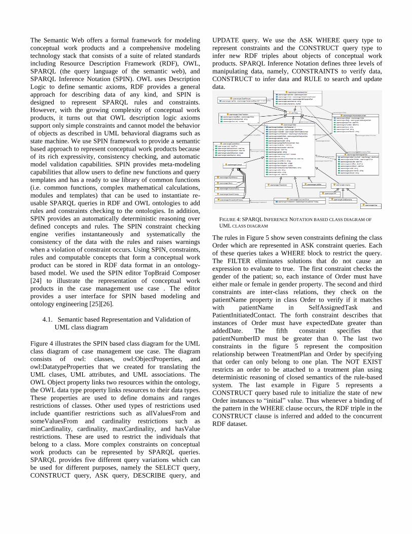
FIGURE 4: SPARQL INFERENCE NOTATION BASED CLASS DIAGRAM OF
UML CLASS DIAGRAM
The Semantic Web offers a formal framework for modeling
conceptual work products and a comprehensive modeling
technology stack that consists of a suite of related standards
including Resource Description Framework (RDF), OWL,
SPARQL (the query language of the semantic web), and
SPARQL Inference Notation (SPIN). OWL uses Description
Logic to define semantic axioms, RDF provides a general
approach for describing data of any kind, and SPIN is
designed to represent SPARQL rules and constraints.
However, with the growing complexity of conceptual work
products, it turns out that OWL description logic axioms
support only simple constraints and cannot model the behavior
of objects as described in UML behavioral diagrams such as
state machine. We use SPIN framework to provide a semantic
based approach to represent conceptual work products because
of its rich expressivity, consistency checking, and automatic
model validation capabilities. SPIN provides meta-modeling
capabilities that allow users to define new functions and query
templates and has a ready to use library of common functions
(i.e. common functions, complex mathematical calculations,
modules and templates) that can be used to instantiate re-
usable SPARQL queries in RDF and OWL ontologies to add
rules and constraints checking to the ontologies. In addition,
SPIN provides an automatically deterministic reasoning over
defined concepts and rules. The SPIN constraint checking
engine verifies instantaneously and systematically the
consistency of the data with the rules and raises warnings
when a violation of constraint occurs. Using SPIN, constraints,
rules and computable concepts that form a conceptual work
product can be stored in RDF data format in an ontology-
based model. We used the SPIN editor TopBraid Composer
[24] to illustrate the representation of conceptual work
products in the case management use case . The editor
provides a user interface for SPIN based modeling and
ontology engineering [25][26].
4.1. Semantic based Representation and Validation of
UML class diagram
Figure 4 illustrates the SPIN based class diagram for the UML
class diagram of case management use case. The diagram
consists of owl: classes, owl:ObjectProperties, and
owl:DatatypeProperties that we created for translating the
UML clases, UML attributes, and UML associations. The
OWL Object property links two resources within the ontology,
the OWL data type property links resources to their data types.
These properties are used to define domains and ranges
restrictions of classes. Other used types of restrictions used
include quantifier restrictions such as allValuesFrom and
someValuesFrom and cardinality restrictions such as
minCardinality, cardinality, maxCardinality, and hasValue
restrictions. These are used to restrict the individuals that
belong to a class. More complex constraints on conceptual
work products can be represented by SPARQL queries.
SPARQL provides five different query variations which can
be used for different purposes, namely the SELECT query,
CONSTRUCT query, ASK query, DESCRIBE query, and
UPDATE query. We use the ASK WHERE query type to
represent constraints and the CONSTRUCT query type to
infer new RDF triples about objects of conceptual work
products. SPARQL Inference Notation defines three levels of
manipulating data, namely, CONSTRAINTS to verify data,
CONSTRUCT to infer data and RULE to search and update
data.
The rules in Figure 5 show seven constraints defining the class
Order which are represented in ASK constraint queries. Each
of these queries takes a WHERE block to restrict the query.
The FILTER eliminates solutions that do not cause an
expression to evaluate to true. The first constraint checks the
gender of the patient; so, each instance of Order must have
either male or female in gender property. The second and third
constraints are inter-class relations, they check on the
patientName property in class Order to verify if it matches
with patientName in SelfAssignedTask and
PatientInitiatedContact. The forth constraint describes that
instances of Order must have expectedDate greater than
addedDate. The fifth constraint specifies that
patientNumberID must be greater than 0. The last two
constraints in the figure 5 represent the composition
relationship between TreatmentPlan and Order by specifying
that order can only belong to one plan. The NOT EXIST
restricts an order to be attached to a treatment plan using
deterministic reasoning of closed semantics of the rule-based
system. The last example in Figure 5 represents a
CONSTRUCT query based rule to initialize the state of new
Order instances to “initial” value. Thus whenever a binding of
the pattern in the WHERE clause occurs, the RDF triple in the
CONSTRUCT clause is inferred and added to the concurrent
RDF dataset.

FIGURE 5: ILLUSTRATION OF ASK CONSTRAINS TO DESCRIBE ORDER
OBJECTS AND CONSTRUCT TO INITIALIZE ORDERS INITIAL STATES IN
SPARQL INFERENCE NOTATION
FIGURE 6: TRANSITION AND ORDER CLASSES REPRESENTATIONS IN SPARQL Inference Notation
Table 2: Transitions of order’s states
4.2. Semantic Based Representation and Validation of
State Machine
The visual formalisms of the UML state machine have been
used for enabling modular conceptual modeling of complex
systems. Therefore many alternatives for its formal
representation have been proposed for formal model checking
[27][28] [29]. The momentum gained by state machines is due
to their role in formal specification of behaviors in critical
systems (i.e. events, conditions, actions, and constraints). A
state in state machine is defined by a set of invariants whose
values hold unchanged. A transition from one state to another
is verified by guard conditions, and consists of a set of
constraints and rules. Table 2 shows the conditions of
transitions for order objects in the state machine of the case
management use case. The transitions are enumerated from 1
to 12 as they appear in the state machine in Figure 3. The
properties used in guard conditions are defined in classes
definitions (Figure 4).
Transition Guard conditions
T0 Doctor has approved the order and the valid
entry and expected dates have been entered
(optionally).
T1 The order needs an appointment and the date
of appointment is not decided yet.
T2 The order needs an appointment and a date has
been fixed
T3 The imaging or lab test order doesn’t need
appointment and the image or specimen has
been obtained.
T4 A date of the appointment has been fixed for
the order consult.
T5 The examination is done for the order consult.
T6 The appointment date is in the future.
T7 The image or specimen has been obtained.
T8 The order consult is done.
T9 The image or specimen is obtained.
T10 The report of the image or specimen is
pending.
T11 The report of the consult is pending.
T12 The report of the consult has been released.
Figure 6 illustrates the representation in SPARQL Inference
Notation of the classes Order and OrderTransition connected
by the properties casemanager:launchtransition and
casemanager:changeState. The state value is represented as
owl:DatatypeProperties in class order and we use a transition
guard represented by a string datatype called
conditionVerified and a boolean data properties called
launched to control the transitions between states.
As represented in the rule in Figure 5, an order is set to the
state “initial” at the start and reaches the state “resolved” as
the final state. An order can be specified to different class
types, namely consult, imaging, and lab test. These classes
may have different states and transitions. For example, an
order of type lab test or imaging do not have the state
“Waiting for appointment to be scheduled” and “Patient
examined” states rather they have the state “Image or
Specimen Obtained”. Figure 7 illustrates the SPARQL rules
edited on TopBraid composer to model the transitions in the
state machine of objects of type order. The SPARQL RULE
has the pattern DELETE {} INSERT {} Where {} which has a
delete phase in clause DELETE, and an assertion phase in the
clause INSERT and takes place when the condition in the
WHERE clause is verified.


FIGURE 7 SPARQL RULES FOR OBJECT BASED STATE MACHINE TRANSITIONS
The SPARQL rules have been evaluated through a scenario
simulation of objects of class order. The ultimate challenge
was to fire only adequate rules when changes happen, the
results were satisfactory and the rule set is validated
5. Discussion and Conclusion
This paper demonstrates the proof of concept of an ontology-
based technique to provide formal specifications of conceptual
work products of interactive systems. Our approach enables
automatic consistency checking based on UML-style visual
modelling of conceptual work products and through mapping
to SPIN modeling language. We instantiated reusable
SPARQL queries in RDF and OWL ontologies to add
inference rules and constraint checking to the ontology model.
We are among the first to use SPIN for translation of UML
conceptual models. Our experience in doing this work
confirms the extensibility and flexibility of this approach to
large, complex conceptual work products.
Our approach has strategic value to verify interactive systems,
and more generally to OMG’s Ontology Definition
Metamodel (ODM). The OMG has recognized the importance
of logic-supported semantic modelling using ontologies,
which is reflected in the OMG's ODM initiative. The OMG
supports selected methods and platforms through an adoption
process. While the formal specification of conceptual work
products of interactive systems has not been adopted so far,
the need for a specific ODM solution for the verification of
complex specifications of conceptual work products is of
concern. The current OMG’s ODM initiative to define and
standardize ontology metamodel will allow the integration of
our framework with OMG standards
Our solution builds on existing tools of declarative knowledge
modeling for representing specifications of complex
conceptual work products. The UML behavioral state machine
specifies discrete behavior of a part of a designed system
through finite state transitions. The two essential features
behind this task are the in-depth description of states and
orthogonality of transitions. The in-depth description is the
ability of moving back and forth between levels of
abstractions of states by clustering and refinement in states
(i.e. zooming-in and –out). These two properties are fulfilled
by the OR and XOR relationships and they allow
consideration of different levels/cuts in the behavior of an
object. The orthogonality of transitions is the ability to
decompose the transitions into sets of components that can
operate synchronously and independently. This property is
fulfilled by AND decomposition in state machine. It is proved
useful in avoiding blowups on the states because the semantic
of orthogonally permits to concurrently and independently
share states and properties between independent components.
The SPIN used in this approach augmented the conceptual
modeling of UML class diagram and state machine by
providing the required consistency checking and reasoning
capabilities. SPIN is based on the fast performance and rich
expressivity of SPARQL and allows deterministic reasoning
using closed world semantics and unique name assumption
while the other technologies in the semantic stack are
primarily meant for declarative semantics or the semantics that
change relatively slowly. The specifications with dynamic
semantics are numerous and can be found in applications such
as inferencing of new content, and responding to external
stimulus including user-initiated interface actions, time, users'
personal profiles, data on a server and condition changes.
We met our objective to provide domain specific alternatives
to represent UML-based models of complex conceptual work
products. We converted the UML based design of class
diagram and state machine to a semantic web model that

automatically checks the consistency of data and provides the
logical and formal representation of system specifications. We
demonstrated that our approach permits to represent dynamic
semantics such as the behavioral state machine and can be
used for the purpose of model checking of complex and
interactive systems. This development enables important
applications in model checking of critical and complex
systems, a successful verification technique for formal
verification of integrative systems.
The workflow modeling for case management was done using
an implementation of the Business Process Modeling Notation
(BPMN)[30]. We have not yet taken the step to use the
conceptual work product to verify the case management
system in a model checker, but work to develop a translator
for BPMN into the SPIN language for process model checking
is nearly complete [31]. Currently there are few tools to
formally verify BPMN process models. There is some limited
work that looks at choreographies [32] , and other work that
turns BPEL, very similar to BPMN, models into Petri Nets but
those translations do not include data structures which are
critical for conceptual work product verification [33][34][35].
Recent work explores the possibility of translating a subset of
BPMN 2.0 into the input language for the SPIN model checker
(distinct from the SPIN rule language in this paper) [36]. The
SPIN model checker is well suited to verifying that a BPMN
model implements a given conceptual work products because
of its support for C-like data structures, its native message
passing support, and the fact that it is widely deployed with a
proven track record of scaling to large models [37]. The SPIN
model checker input language lends itself rather naturally to
Petri Net like constructs so it is possible to leverage the Petri
Net like semantics of BPMN similar to the work converting
BPEL to Petri Nets, but with the ability to also include data-
objects, data-stores, and message passing to naturally support
the BPMN 2.0 standard. Early experiments with the
translation are encouraging showing the translation to cover
most aspects of the standard somewhat intuitively.
Future work to formally verify if a BPMN process implements
a conceptual work product specification is to convert the
conceptual work product state diagram into a set of linear
temporal logic properties suitable for the SPIN model checker
[38]. The properties combined with the BPMN translation to
the model checker input language will enable the verification
of the entire system. Another approach worth exploring is to
translate the conceptual work product state diagram into an
automaton representing the language of valid sequences of
conceptual work product state transitions and then use that
language to search for sequences in the BPMN model that are
outside the language (e.g., witness traces to property
violations) [39]. Future work will look at the trade-offs
between these two ways to use the conceptual work product
state diagram in formally verifying if a BPMN accomplishes
the intended work in this abstract product.
Finally, this research was funded as part of a larger method to
integrate usable health IT with effective and efficient clinical
workflows [1]. The method, however, is general to critical,
technical interactive systems in many other domains. Verified
models of conceptual work products have several valuable
enabling roles. They are fundamental requirements that
simplify the design of interactive software by providing a
precise understanding of the work products it must accomplish
as output. They enable model checking to verify the
effectiveness of complex systems that will be carried out by
complex interactions between people and computers. One of
the most difficult design problems for those systems is how to
decide the allocation of functionality between people and
computers [2]. Model checking makes it meaningful to
compare and analyze different verified design options for
functionality because they each accomplish equivalent work
products. Comparing design for qualities such as cost-
effectiveness or usability, is similarly only meaningful if each
option has been verified to accomplish equivalent work
products. These are key steps that are needed to realize the
great potential for interactive computing that will be reliably
beneficial to clinical health care and many other critical
domains.
ACKNOWLEDGEMENTS
This research was partially supported by the Agency for
Healthcare Research and Quality under Award Number
R01HS021233 and by the National Library of Medicine of the
National Institutes of Health under Award Number
R01LM011829. The content is solely the responsibility of the
authors and does not necessarily represent the official views of
the funding agency.
References
[1] A. B. L. Berry et al., “Using conceptual work products
of health care to design health IT,” J. Biomed. Inform.,
vol. 59, pp. 15–30, Feb. 2016.
[2] K. A. Butler, E. Mercer, A. Bahrami, and C. Tao,
“Model Checking for Verification of Interactive
Health IT Systems,” in Conference: AMIA 2015
Symposium, At San Francisco, 2015.
[3] K. A. Butler, J. Zhang, C. Esposito, A. Bahrami, R.
Hebron, and D. Kieras, “Work-centered design: a case
study of a mixed-initiative scheduler,” in Proceedings
of the SIGCHI conference on Human factors in
computing systems, 2007, pp. 747–756.
[4] D. Billman, M. Feary, D. Schreckenghost, and L.
Sherry, “Needs analysis and technology alignment
method: A case study of planning work in an
International Space Station Controller Group--Part 1,”
J. Cogn. Eng. Decis. Mak., vol. 9, no. 2, pp. 169–185,
2015.
[5] K. A. Butler, A. J. Hunt, and J. Muehleisen,
“Ontology models for interaction design: case study of

online support,” in CHI’10 Extended Abstracts on
Human Factors in Computing Systems, 2010, pp.
4525–4540.
[6] D. Billman, L. Arsintescucu, M. Feary, J. Lee, A.
Smith, and R. Tiwary, “Benefits of matching domain
structure for planning software,” in Proceedings of the
2011 annual conference on Human factors in
computing systems - CHI ’11, 2011, p. 2521.
[7] T. C et al., “A Work Domain Ontology for Modeling
Emergency Department Workflow,” in International
Workshop on Semantic Web Applications and Tools
for Life Sciences (SWAT4LS), 2014.
[8] Jacobson and Ivar, Object-oriented software
engineering : a use case driven approach. Addison-
Wesley Pub, 2005.
[9] S. A. White, BPMN modeling and reference guide:
understanding and using BPMN. Future Strategies
Inc., 2008.
[10] A. H. Khan, “Consistency of UML based designs
using ontology reasoners,” 2013.
[11] AtlanMod, “AtlanMod metamodel zoo,” 2007.
[Online]. Available: http://www.emn.fr/. [Accessed:
01-Jan-2016].
[12] C. Wilke and B. Demuth, “UML is still inconsistent!
How to improve OCL Constraints in the UML 2.3
Superstructure,” Electron. Commun. EASST, vol. 44,
2011.
[13] H. Knublauch, “SPIN - Modeling Vocabulary,” W3C,
2011. [Online]. Available:
http://www.w3.org/Submission/spin-modeling/.
[14] Case Management Society of America, “Standards of
Practice for Case Management,” 2010.
[15] OMG, “Ontology Definition Metamodel Version 1.1,”
no. August, 2014.
[16] I. Reinhartz-Berger and D. Dori, “Object-Process
Methodology (OPM) vs. UML-a Code Generation
Perspective.,” in CAiSE Workshops (1), 2004, pp.
275–286.
[17] M. Elaasar and L. Briand, “An overview of UML
consistency management,” 2004.
[18] D. Allemang and J. Hendler, Semantic web for the
working ontologist: effective modeling in RDFS and
OWL. Elsevier, 2011.
[19] L. Kuzniarz, Z. Huzar, G. Reggio, J. L. Sourrouille,
and M. Staron, “Workshop on Consistency Problems
in UML-based Software Development II,”
Organization, vol. 1103, p. 1581, 2003.
[20] K. Baclawski et al., “Extending the Unified Modeling
Language for ontology development,” Softw. Syst.
Model., vol. 1, no. 2, pp. 142–156, 2014.
[21] M. Mehrolhassani and E. . Atilla, Developing
Ontology Based Applications of Semantic Web Using
UML to OWL Conversion. Springer, 2008.
[22] J. Zedlitz and N. Luttenberger, “Data Types in UML
and OWL-2,” in SEMAPRO 2013 : The Seventh
International Conference on Advances in Semantic
Processing, 2013.
[23] A. H. Khan and I. Porres, “Consistency of UML class,
object and statechart diagrams using ontology
reasoners,” J. Vis. Lang. Comput., vol. 26, pp. 42–65,
Feb. 2015.
[24] O. ComposerTM
, “opBraid ComposerTM
,” 2016.
[Online]. Available:
http://www.topquadrant.com/tools/ide-topbraid-
composer-maestro-edition/.
[25] “TopBraid Composer TM
Getting Started Guide,”
2011.
[26] TopBraid, “The TopBraid SPIN API,” 2014. .
[27] D. Latella, I. Majzik, and M. Massink, “Automatic
Verification of a Behavioural Subset of UML
Statechart Diagrams Using the SPIN Model-checker,”
Form. Asp. Comput., vol. 11, no. 6, pp. 637–664, Dec.
1999.
[28] E. Mikk, Y. Lakhnech, and M. Siegel, “Hierarchical
Automata as Model for Statecharts.,” in Lecture Notes
in Computer Science, 1997, vol. 1345, pp. 181–196.
[29] T. Schäfer, A. Knapp, and S. Merz, “Model Checking
UML State Machines and Collaborations,” Electron.
Notes Theor. Comput. Sci., vol. 55, no. 3, pp. 357–
369, Oct. 2001.
[30] Object Management Group, “Business Process Model
and Notation.” [Online]. Available:
http://www.bpmn.org/.
[31] SPIN, “Verifying Multi-threaded Software with Spin.”
[Online]. Available: http://spinroot.com.
[32] E. Solaiman, W. Sun, and C. Molina-Jimenez, “A
Tool for the Automatic Verification of BPMN
Choreographies,” in 2015 IEEE International
Conference on Services Computing, 2015, pp. 728–
735.
[33] C. Stahl, “A Petri net semantics for BPEL,” 2005.
[34] N. Lohmann, “A Feature-Complete Petri Net
Semantics for WS-BPEL 2.0,” in Web Services and
Formal Methods, Berlin, Heidelberg: Springer Berlin
Heidelberg, 2007, pp. 77–91.
[35] S. Hinz, K. Schmidt, and C. Stahl, “Transforming
BPEL to Petri Nets,” Springer, Berlin, Heidelberg,
2005, pp. 220–235.
[36] J. Visker and E. Mercer, “Automatic translation of
BPMN Process Models to PROMELA,” Prep., 2017.
[37] http://spinroot.com, “Verifying Multi-threaded
Software with Spin.” [Online]. Available:
http://spinroot.com/spin/whatispin.html.
[38] E. M. Clarke, E. A. Emerson, and A. P. Sistla,
“Automatic verification of finite-state concurrent
systems using temporal logic specifications,” ACM
Trans. Program. Lang. Syst., vol. 8, no. 2, pp. 244–
263, Apr. 1986.
[39] D. Giannakopoulou and K. Havelund, “Automata-
based verification of temporal properties on running
programs,” in Proceedings 16th Annual International
Conference on Automated Software Engineering (ASE
2001), pp. 412–416.