Self-Sustainability in Nano Unmanned Aerial Vehicles: A...
10
Self-Sustainability in Nano Unmanned Aerial Vehicles: A Blimp Case Study Daniele Palossi, Andres Gomez, Stefan Draskovic, Kevin Keller, Luca Benini , , Lothar Thiele DEI, University of Bologna, Italy. Email: [email protected] D-ITET, ETH Zürich, Switzerland. Email: {rstname.lastname}@ee.ethz.ch ABSTRACT Nowadays nano Unmanned Aerial Vehicles (UAV’s), such as quad- copters, have very limited ight times, tens of minutes at most. The main constraints are energy density of the batteries and the engine power required for ight. In this work, we present a nano-sized blimp platform, consisting of a helium balloon and a rotorcraft. Thanks to the lift provided by helium, the blimp requires relatively little energy to remain at a stable altitude. We also introduce the concept of duty-cycling high power actuators, to reduce the energy requirements for hovering even further. With the addition of a solar panel, it is even feasible to sustain tens or hundreds of ight hours in modest lighting conditions (including indoor usage). A functioning 52 gram prototype was thoroughly characterized and its lifetime was measured in dierent harvesting conditions. Both our system model and the experimental results indicate our proposed platform requires less than 200 mW to hover in a self sustainable fashion. This represents, to the best of our knowledge, the rst nano-size UAV for long term hovering with low power requirements. CCS CONCEPTS • Computer systems organization → Embedded systems; KEYWORDS Self sustainability, energy neutrality, UAV, blimp ACM Reference format: Daniele Palossi, Andres Gomez, Stefan Draskovic, Kevin Keller, Luca Benini , , Lothar Thiele. 2017. Self-Sustainability in Nano Unmanned Aerial Vehicles: A Blimp Case Study. In Proceedings of CF’17, Siena, Italy, May 15-17, 2017, 10 pages. DOI: http://dx.doi.org/10.1145/3075564.3075580 1 INTRODUCTION The popularity of nano unmanned aerial vehicles (nano-size UAV) in the past few years has increased dramatically. These nano-size UAVs are used for aerial mapping, photography, surveillance, sport, entertainment and many other uses. Despite signicant research eort in past years, nano-size UAVs are still limited, in most cases, to tens of minutes of ight. This has limited their applicability, since longer missions require additional infrastructure to replenish them at service stations [1, 2]. Permission to make digital or hard copies of all or part of this work for personal or classroom use is granted without fee provided that copies are not made or distributed for prot or commercial advantage and that copies bear this notice and the full citation on the rst page. Copyrights for components of this work owned by others than ACM must be honored. Abstracting with credit is permitted. To copy otherwise, or republish, to post on servers or to redistribute to lists, requires prior specic permission and/or a fee. Request permissions from [email protected]. CF’17, Siena, Italy © 2017 ACM. 978-1-4503-4487-6/17/05. . . $15.00 DOI: http://dx.doi.org/10.1145/3075564.3075580 A nano-sized UAV with long ight times could have a number of innovative applications in surveillance, smart buildings, agricul- ture and many other elds. Even if a nano-size UAV is able to y only a few days, which is already signicantly longer than existing systems, it would also be able to collect, process and transmit infor- mation from dierent sensors such as environmental data, audio, video and still cover a large area. Depending on the weather con- ditions, it could also be used in outdoor scenarios for surveillance, search and rescue, or mapping, to name a few applications. The reduced ight times of existing UAV’s are mostly due to the power required for the rotors to generate enough thrust. Even for the nano-size class of UAV’s, which typically weigh ∼50 g or less, around 5 W of power are needed for the mechanical system alone [3]. This does not even account for computational requirements of current research trends towards autonomous systems, which require power hungry sensor fusion and real-time control for on- line path planning and collision detection/avoidance algorithms [4]. Given the current battery densities of 500 / and their limited technology scaling, nano UAV’s with ight times of days or weeks will require novel methodologies that combine both hardware and software. Energy harvesting has been successfully demonstrated in a num- ber of UAV platforms as a way to extend their ight times [5, 6]. Photovoltaic is a common form of harvesting due to the abundance of light and the high power density of solar cells [7]. Harvesting energy is one side of the equation, and to really maximize the life- time of a UAV, its power requirements must be minimized as well. For many years, power management techniques like duty-cycling have been successfully deployed in battery-based cyber-physical systems in order to reduce the average power consumption and consequently extend the battery lifetime. Traditional nano UAV’s, however, are fundamentally incompatible with duty-cycling. If a quadrotor tried to shut down its rotors, it will either crash very quickly or incur a signicant energy penalty to counteract the acceleration due to gravity. Fortunately, another type of UAV has certain properties which make it compatible with duty-cycling. A nano-sized blimp is a perfect candidate for long ight times because helium, a lighter- than-air gas, can provide lift and signicantly reduce the energy requirements for ight. Even though helium provides lift, a perfect balance with a blimp’s weight is almost impossible since even the smallest dierence between the system’s weight and its lift will result in an acceleration that will eventually drive the blimp to the ground, to the roof or to the stratosphere [8]. Designing a blimp that is able to hover (i.e. that is able to maintain a desired altitude within a given tolerance range) for a prolonged period of time remains a challenge to this day. Though hovering is a one dimensional problem, it is a fundamental building block for the development of fully autonomous UAVs with extended ight times.
-
Upload
truongquynh -
Category
Documents
-
view
214 -
download
1
Transcript of Self-Sustainability in Nano Unmanned Aerial Vehicles: A...

Self-Sustainability in Nano Unmanned Aerial Vehicles:A Blimp Case Study
Daniele Palossi1, Andres Gomez1, Stefan Draskovic1, Kevin Keller1, Luca Benini1,2, Lothar Thiele12DEI, University of Bologna, Italy. Email: [email protected]
1D-ITET, ETH Zürich, Switzerland. Email: {�rstname.lastname}@ee.ethz.ch
ABSTRACTNowadays nano Unmanned Aerial Vehicles (UAV’s), such as quad-copters, have very limited �ight times, tens of minutes at most. Themain constraints are energy density of the batteries and the enginepower required for �ight. In this work, we present a nano-sizedblimp platform, consisting of a helium balloon and a rotorcraft.Thanks to the lift provided by helium, the blimp requires relativelylittle energy to remain at a stable altitude. We also introduce theconcept of duty-cycling high power actuators, to reduce the energyrequirements for hovering even further. With the addition of a solarpanel, it is even feasible to sustain tens or hundreds of �ight hours inmodest lighting conditions (including indoor usage). A functioning52 gram prototype was thoroughly characterized and its lifetimewas measured in di�erent harvesting conditions. Both our systemmodel and the experimental results indicate our proposed platformrequires less than 200mW to hover in a self sustainable fashion.This represents, to the best of our knowledge, the �rst nano-sizeUAV for long term hovering with low power requirements.
CCS CONCEPTS• Computer systems organization → Embedded systems;
KEYWORDSSelf sustainability, energy neutrality, UAV, blimp
ACM Reference format:Daniele Palossi1, Andres Gomez1, Stefan Draskovic1, Kevin Keller1, Luca
Benini1,2, Lothar Thiele1. 2017. Self-Sustainability in Nano Unmanned AerialVehicles: A Blimp Case Study. In Proceedings of CF’17, Siena, Italy, May 15-17,2017, 10 pages.DOI: http://dx.doi.org/10.1145/3075564.3075580
1 INTRODUCTIONThe popularity of nano unmanned aerial vehicles (nano-size UAV)in the past few years has increased dramatically. These nano-sizeUAVs are used for aerial mapping, photography, surveillance, sport,entertainment and many other uses. Despite signi�cant researche�ort in past years, nano-size UAVs are still limited, in most cases,to tens of minutes of �ight. This has limited their applicability, sincelonger missions require additional infrastructure to replenish themat service stations [1, 2].
Permission to make digital or hard copies of all or part of this work for personal orclassroom use is granted without fee provided that copies are not made or distributedfor pro�t or commercial advantage and that copies bear this notice and the full citationon the �rst page. Copyrights for components of this work owned by others than ACMmust be honored. Abstracting with credit is permitted. To copy otherwise, or republish,to post on servers or to redistribute to lists, requires prior speci�c permission and/or afee. Request permissions from [email protected]’17, Siena, Italy© 2017 ACM. 978-1-4503-4487-6/17/05. . . $15.00DOI: http://dx.doi.org/10.1145/3075564.3075580
A nano-sized UAV with long �ight times could have a numberof innovative applications in surveillance, smart buildings, agricul-ture and many other �elds. Even if a nano-size UAV is able to �yonly a few days, which is already signi�cantly longer than existingsystems, it would also be able to collect, process and transmit infor-mation from di�erent sensors such as environmental data, audio,video and still cover a large area. Depending on the weather con-ditions, it could also be used in outdoor scenarios for surveillance,search and rescue, or mapping, to name a few applications.
The reduced �ight times of existing UAV’s are mostly due to thepower required for the rotors to generate enough thrust. Even forthe nano-size class of UAV’s, which typically weigh ∼50 g or less,around 5 W of power are needed for the mechanical system alone[3]. This does not even account for computational requirementsof current research trends towards autonomous systems, whichrequire power hungry sensor fusion and real-time control for on-line path planning and collision detection/avoidance algorithms[4]. Given the current battery densities of 500 J/д and their limitedtechnology scaling, nano UAV’s with �ight times of days or weekswill require novel methodologies that combine both hardware andsoftware.
Energy harvesting has been successfully demonstrated in a num-ber of UAV platforms as a way to extend their �ight times [5, 6].Photovoltaic is a common form of harvesting due to the abundanceof light and the high power density of solar cells [7]. Harvestingenergy is one side of the equation, and to really maximize the life-time of a UAV, its power requirements must be minimized as well.For many years, power management techniques like duty-cyclinghave been successfully deployed in battery-based cyber-physicalsystems in order to reduce the average power consumption andconsequently extend the battery lifetime. Traditional nano UAV’s,however, are fundamentally incompatible with duty-cycling. If aquadrotor tried to shut down its rotors, it will either crash veryquickly or incur a signi�cant energy penalty to counteract theacceleration due to gravity.
Fortunately, another type of UAV has certain properties whichmake it compatible with duty-cycling. A nano-sized blimp is aperfect candidate for long �ight times because helium, a lighter-than-air gas, can provide lift and signi�cantly reduce the energyrequirements for �ight. Even though helium provides lift, a perfectbalance with a blimp’s weight is almost impossible since even thesmallest di�erence between the system’s weight and its lift willresult in an acceleration that will eventually drive the blimp to theground, to the roof or to the stratosphere [8]. Designing a blimp thatis able to hover (i.e. that is able to maintain a desired altitude withina given tolerance range) for a prolonged period of time remainsa challenge to this day. Though hovering is a one dimensionalproblem, it is a fundamental building block for the development offully autonomous UAVs with extended �ight times.

CF’17, May 15-17, 2017, Siena, Italy D. Palossi et al.
In this work, we will explore how traditional power managementtechniques, usually applied to digital systems, can be extended tohigh power actuators, such as rotors. We demonstrate that thesetechniques can signi�cantly reduce the energy requirement forhovering. We will study two types of hovering, one in which thrustis generated constantly, and another with duty-cycled rotors. Theformer can achieve hovering with a relatively small deviation fromthe desired altitude, at the price of high power consumption. Thelatter reduces the average power consumption and leads to a longer�ight time, but introduces a larger tolerance to the desired altitude.Our proposed platform, consisting of a single rotor controlled bya low-power MCU and a 0.4m3 helium balloon, weighs a total of52 g and is able to hover for tens to hundreds of hours, requiringonly commercial-o�-the-shelf components and modest light condi-tions. Our initial prototype has some limitations in its capability toadapt to changing environmental conditions: there is no dynamiccontrol loop for variations in temperature, humidity and pressure.Nevertheless, it lays the ground work for an energy autonomousnano-blimp, capable of complex cognitive skills (e.g. autonomousnavigation, path planning, etc.) relying only on local sensing andprocessing (i.e. inertial and visual), due to the relaxed real-timeconstraints.
The main contributions of our work are:
- A system model capable of predicting an energy harvestingblimp’s lifetime given probabilistic harvesting conditions,solar panel size, and battery capacity.
- An optimization formulation for distributing a blimp’s pay-load, thus determining the battery to solar panel weightratio which maximizes the blimps lifetime.
- A study of two types of hovering mechanisms: constantand duty-cycling, exhibiting a trade-o� between energyrequirements and hovering precision.
- A thorough evaluation and model comparison of our 52 gblimp prototype. Thanks to its power management, it re-quires only 198mW of input power for self-sustainablehovering as opposed to 576mW needed for continuousoperation of the rotor.
The remainder of this paper is organized as follows: In the nextsection, we discuss a general classi�cation of UAV’s with di�erentsizes and aerodynamics, as well as existing solutions that integrateenergy harvesting. In Sec. 3, we discuss the preliminary overviewof hovering, and duty-cycling and self-sustainability is presented.In Sec. 4, we present our system model with probabilistic energyharvesting, and lifetime estimation. In Sec. 5, we discuss in detailthe implementation of our nano-blimp prototype. In Sec. 6, wecharacterize our prototype and evaluate hovering with and withoutpower management. Finally, we conclude our work in Sec. 7.
2 RELATEDWORKUnmanned Aerial Vehicles (UAVs) with solar energy harvesting,have been studied for many years. UAV’s, however, can be classi�edaccording to di�erent criteria. Each UAV class has its own challengesand limitations, which are tied to the existing technologies in the�elds of mechanical propulsion, material science, and electricalengineering.
2.1 UAV Classi�cationRotorcrafts can be classi�ed on the basis of their sizes and powerconsumption, as reported in Tab. 1. For the sake of generality, thesize refers to the core frame of the vehicle and not the in�atableparts, like balloons in the case of blimps. An additional classi�cationparameter is the vehicle’s sensitivity to environmental conditions(e.g. wind, temperature, pressure, etc.), which depends on the ve-hicle’s dimension and speed range. The blimp presented in thispaper is considered a nano UAV due to its low power consumptionof ∼200 mW, limited payload of 55 g, and small frame measuringabout 4 × 4 cm.
Vehicle Class � : Weight [cm:kд] Power [W ] On-board Devicestd-size[9] ∼ 50 : ≥ 1 ≥ 100 Desktop
micro-size[10] ∼ 25 : ∼ 0.5 ∼ 50 Embedded
nano-size[3] ∼ 10 : ∼ 0.05 ∼ 5 MCU
pico-size[11] ∼ 2 : ∼ 0.005 ∼ 0.1 ULP
Table 1: Rotorcraft UAV’s classi�cation by vehicle class-size.A second dimension for classi�cation is the type of unmanned
aerial vehicles: �xed wing, rotorcraft, and blimps. The main trade-o�s between the aforementioned types are their maneuverabil-ity/controllability and their energy requirements. As depicted inFig. 1-A, a traditional criterion to classify UAV’s is given by thetrade-o� between maneuverability and endurance [12]. In this workwe use the concept of agility, as shown in Fig. 1-B, de�ned as: theminimum space required by the vehicle to accomplish a given ma-neuver, at the minimum control speed. Under such de�nition blimpsare more agile than �xed wing vehicles, since they can performsharp turns within a limited space at reduced speeds. This notion ofagility is particularly relevant for indoor applications, where humansafety is an important factor. In contrast, blimps are more sensitiveto environmental conditions than other UAV types, especially inoutdoor scenarios.
Rotorcraft
Fixed-Wings
Blimps
Endurance
Maneuverability Rotorcraft
Fixed-Wings
Blimps
Endurance
Agility
A B
Figure 1: Classi�cation of UAV’s based on their endurancevs. maneuverability (A) and endurance vs. agility (B).
Rotorcraft These vehicles have one or more rotors and canachieve stable hovering and precise �ight by adjusting rotor speedand balancing di�erent forces. Rotorcrafts are highly maneuverable,can operate in a wide speed range and can take-o� and land verti-cally. They also have very high energy consumption since they needto generate propulsion continuously. The most common rotorcraftis the quadrotor, that has four rotors and changes the rotation ratioamong them to generate lift [10].

Self-Sustainability in Nano Unmanned Aerial Vehicles:A Blimp Case Study CF’17, May 15-17, 2017, Siena, Italy
Fixed Wing These aircrafts, also called airplanes, use �xedwings to generate enough lift for �ight. The shape of the wingpushes air over the top of the wing to �ow more rapidly than un-derneath it, causing a di�erence in pressure and generating lift [13].Though �xed-wing UAV’s have lower energy requirements andlonger �ight times compared to quadrotors, they cannot hover ormake tight turns, which can limit their deployment in certain appli-cations. In recent years, a new hybrid category has received partic-ular attention: convertibles UAV’s [14]. They combine rotorcraft fortake-o� and landing maneuvers with �xed wing for energy-e�cientlong-range �ights.
Blimps These vehicles, also called airships, have close to neutralbuoyancy and can be steered and propelled through the air usingone or more propellers [15]. Contrary to other types of UAV’s, theycan hover thanks to the lift generated by a lighter-than-air gas, andthus require relatively little energy for movement at low speeds.Due to their reduced energy requirements, level of agility andsensitivity to the environment, nano-size blimps are very suitablecandidates for indoor application scenarios.
2.2 Energy Harvesting UAV’sDespite the challenges associated with high power consumptionin quadrotors, researchers have been able to design solar-poweredversions. The solarcopter, proposed in [16], uses a 0.96m2 monocrys-talline solar panel, generating 136.8W in favorable lighting con-ditions. A specially designed frame with a high stress resistanceto weight ratio was required for the 925д quadrotor to �y. Due toits lack of energy storage, this design has �ight times limited toperiods of high energy availability. One alternative energy sourcefor UAV’s with the potential for ultra long lifetimes are laser powerbeams [17]. By using a special laser power supply, a ground sta-tion can wirelessly direct power to a moving UAV. The authorsof [6] present a 1kд quadcopter prototype that was able to �y for12.45 hours powered by laser beams. This class of systems requiresline-of-sight and additional expensive infrastructure which is notfeasible in many applications scenarios.
Fixed-wing UAVs have also been equipped with solar panelsto harvest energy during the day. In [18], for example, the Sky-Sailor airplane was able to �y 27 hours during summertime witha wingspan of 3.2m using solar panels. Sunsailor [19] achieved athree day �ight using a 4.2m wingspan and weighing 3.6kд. TheHelios prototype [20] was developed by NASA for high altitude andlong endurance �ights. With a 75m wingspan and a gross weightof up to 930kд, it was able to prove sustainable in the stratosphere[5]. AtlantikSolar [13] is a 5.6m-wingspan, 6.8kд of weight, solar-powered low-altitude long-endurance UAV capable of a continuous�ight of 81.5 hours, covering a total of 2316km. These works demon-strate that standard (and large) size �xed wing airplanes are able toharvest enough energy for long �ight times. Nonetheless, it is alsounderstood that these systems must have a scale large enough forthe required energy storage systems and propulsion. In addition,these systems su�er from the same limitations of all airplanes: theinability to hover and perform sharp turns due to the minimumhigh speed required to operate.
Solar-powered blimps o�er the best-case scenario for UAV’srequiring ultra long �ight times, due to their reduced energy re-quirements. In [21] the trade-o�s between solar panel weight andpower produced is chosen for a high altitude blimp and validated
using design parameters from [22, 23]. In [24], the e�ect of thecurvature of the balloon surface and the corresponding changes inthe energy output is analyzed for a solar powered lighter-than-airUAV platform. All of these studies focus on large scale blimps, sincethey are required to withstand adverse weather conditions for pro-longed periods of time, particularly those meant to operate in thestratosphere. These blimps are up to 400m in length, and consume100kW . In the case of [24], the blimp has a volume of 24 m3 andrequires only 100W of power.
Our work focuses on a nano-scale blimp that, with a weight ofless than 55д and a balloon of 0.4m3 can reach self-sustainabilitywith only 198mW of input power. To the best of our knowledge,this work presents the �rst nano-size UAV capable of continuous,long term hovering. Thanks to its energy harvesting capabilityand the low de�ation rates of mylar balloons, the blimp platformpresented in this paper could conceivably hover for several weeksin indoor environments.
3 PRELIMINARIESThough there is a current trend towards autonomous and intelligentaerial vehicles, most of them are either very large systems, or havereduced �ight times in the order of minutes. To understand thebasic problem of why self-sustainable nano-UAV’s have generallybeen infeasible, it is enough to look at the problem of hovering.Though it is simpler than free movement inR3, since it only involvestranslation in the vertical axis, it demonstrates the large energyrequirements for nano-UAV �ight.
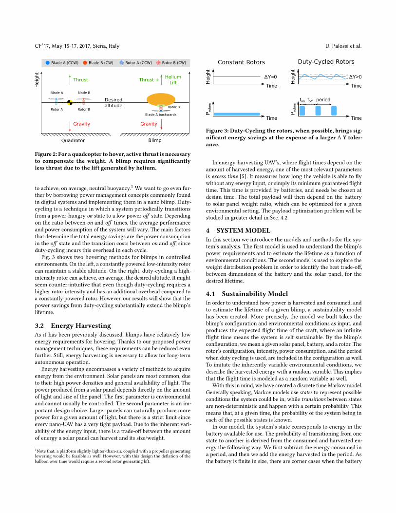
3.1 HoveringOne of the most basic tasks that non-airplane UAV’s need to performis hovering, which keeps the aircraft at a stable altitude. Fig. 2 showsa basic comparison between a hovering quadcoptor and blimp. Thequadcoptor needs to continuously generate thrust from its fourrotors to be able to counteract gravity. This results in an enormouspower requirement. A blimp, on the contrary, leverages a lighter-than-air gas like helium to generate lift passively. This signi�cantlyreduces the energy requirements since relatively little thrust isnecessary to counteract gravity.
Though in theory a blimp can passively hover with neutral buoy-ancy, this is very hard to achieve in practice. For starters, choosing apassive hovering altitude would require perfectly calibrated weightsto o�set a balloon’s lift in a given environment. Furthermore, anysmall change to the environmental conditions (e.g. temperature,pressure, humidity, etc.) will a�ect the balloon and its steady-statealtitude. But even in a controlled environment, the balloon’s de�a-tion rate will quickly result in slightly negative buoyancy, whichwill eventually drive the balloon to the ground. For a balloon tohover long term at a desired altitude, active control is thus required.The focus of this paper is to reduce the power requirements ofhovering in controlled environments to maximize the balloon’s life-time. Though a more realistic scenario includes environments withdynamic conditions, this would require adaptive control methodsthat simply adjust some parameters based on sensor readings (e.g.pressure sensor).
Our proposed blimp platform will be slightly a heavier-than-airsystem, such that it falls slowly and requires relatively little energy
CF’17, May 15-17, 2017, Siena, Italy D. Palossi et al.
Blade A (CCW) Blade B (CW) Rotor A (CCW) Rotor B (CW)
Heig
ht
Blade A Blade B
Rotor BRotor A
Desired
altitude
Gravity Gravity
Thrust Thrust +Helium
Lift
Quadrotor Blimp
Blade A backwards
Rotor B
Figure 2: For a quadcopter to hover, active thrust is necessaryto compensate the weight. A blimp requires signi�cantlyless thrust due to the lift generated by helium.
to achieve, on average, neutral buoyancy.1 We want to go even fur-ther by borrowing power management concepts commonly foundin digital systems and implementing them in a nano blimp. Duty-cycling is a technique in which a system periodically transitionsfrom a power-hungry on state to a low power o� state. Dependingon the ratio between on and o� times, the average performanceand power consumption of the system will vary. The main factorsthat determine the total energy savings are the power consumptionin the o� state and the transition costs between on and o�, sinceduty-cycling incurs this overhead in each cycle.
Fig. 3 shows two hovering methods for blimps in controlledenvironments. On the left, a constantly powered low-intensity rotorcan maintain a stable altitude. On the right, duty-cycling a high-intensity rotor can achieve, on average, the desired altitude. It mightseem counter-intuitive that even though duty-cycling requires ahigher rotor intensity and has an additional overhead compared toa constantly powered rotor. However, our results will show that thepower savings from duty-cycling substantially extend the blimp’slifetime.
3.2 Energy HarvestingAs it has been previously discussed, blimps have relatively lowenergy requirements for hovering. Thanks to our proposed powermanagement techniques, these requirements can be reduced evenfurther. Still, energy harvesting is necessary to allow for long-termautonomous operation.
Energy harvesting encompasses a variety of methods to acquireenergy from the environment. Solar panels are most common, dueto their high power densities and general availability of light. Thepower produced from a solar panel depends directly on the amountof light and size of the panel. The �rst parameter is environmentaland cannot usually be controlled. The second parameter is an im-portant design choice. Larger panels can naturally produce morepower for a given amount of light, but there is a strict limit sinceevery nano-UAV has a very tight payload. Due to the inherent vari-ability of the energy input, there is a trade-o� between the amountof energy a solar panel can harvest and its size/weight.
1Note that, a platform slightly lighter-than-air, coupled with a propeller generatinglowering would be feasible as well. However, with this design the de�ation of theballoon over time would require a second rotor generating lift.
Constant Rotors Duty-Cycled Rotors
Protors
Time
Height
Time
ΔY=0
Protors
Time
Height
Time
ΔY>0
ton toff period
Figure 3: Duty-Cycling the rotors, when possible, brings sig-ni�cant energy savings at the expense of a larger ∆ Y toler-ance.
In energy-harvesting UAV’s, where �ight times depend on theamount of harvested energy, one of the most relevant parametersis excess time [5]. It measures how long the vehicle is able to �ywithout any energy input, or simply its minimum guaranteed �ighttime. This time is provided by batteries, and needs be chosen atdesign time. The total payload will then depend on the batteryto solar panel weight ratio, which can be optimized for a givenenvironmental setting. The payload optimization problem will bestudied in greater detail in Sec. 4.2.
4 SYSTEM MODELIn this section we introduce the models and methods for the sys-tem’s analysis. The �rst model is used to understand the blimp’spower requirements and to estimate the lifetime as a function ofenvironmental conditions. The second model is used to explore theweight distribution problem in order to identify the best trade-o�,between dimensions of the battery and the solar panel, for thedesired lifetime.
4.1 Sustainability ModelIn order to understand how power is harvested and consumed, andto estimate the lifetime of a given blimp, a sustainability modelhas been created. More precisely, the model we built takes theblimp’s con�guration and environmental conditions as input, andproduces the expected �ight time of the craft, where an in�nite�ight time means the system is self sustainable. By the blimp’scon�guration, we mean a given solar panel, battery, and a rotor. Therotor’s con�guration, intensity, power consumption, and the periodwhen duty cycling is used, are included in the con�guration as well.To imitate the inherently variable environmental conditions, wedescribe the harvested energy with a random variable. This impliesthat the �ight time is modeled as a random variable as well.
With this in mind, we have created a discrete time Markov model.Generally speaking, Markov models use states to represent possibleconditions the system could be in, while transitions between statesare non-deterministic and happen with a certain probability. Thismeans that, at a given time, the probability of the system being ineach of the possible states is known.
In our model, the system’s state corresponds to energy in thebattery available for use. The probability of transitioning from onestate to another is derived from the consumed and harvested en-ergy the following way. We �rst subtract the energy consumed ina period, and then we add the energy harvested in the period. Asthe battery is �nite in size, there are corner cases when the battery

Self-Sustainability in Nano Unmanned Aerial Vehicles:A Blimp Case Study CF’17, May 15-17, 2017, Siena, Italy
consumption
harvesting
n − 2 n − 1 n n + 1
1
0.5
0.15
0.250.1
Figure 4: A transition from n to possible new states
is empty and full, and these will be discussed below. The time stepof this discrete model is one duty-cycle period. There is a compu-tational trade-o� between the number of states and the accuracyof the model. However, we found a satisfactory solution by havingthe di�erence between two consecutive energy states an order ofmagnitude smaller than the energies consumed or harvested in oneperiod.
Besides the many states representing di�erent energy levels,there is an additional error state. This state is entered when therotor fails to run due to insu�cient energy. This state is absorbing,meaning that once entered, the system stays in the error state.Because we assume that energy is �rst consumed during a transitionbetween two states, before being harvested, the whole analysis ispessimistic w.r.t. the error state. By observing the probability of thesystem being in the error state after running for an amount of time,we can understand whether the blimp is operating at that time ornot.
The state representing the battery fully charged is also notable.This is because the battery is �nite, and if too much energy isharvested, the battery saturates to the fully charged state.
Before formally de�ning the Markov model, we will present anillustrative example to familiarize the reader to the underlayingconcepts.
Example. The example in Figure 4 helps to understand the systemmodel. Let the system be in staten at time step τ , meaning its energylevel is n at that time. We will determine the state of the system atthe next time step τ + 1, after one period of operation.
During the period, we assume energy is �rst consumed and thenharvested. Assume that the di�erence between two energy levelsis one energy unit. Let the system consume 2 units of energy perperiod, and harvest some units of energy per period with the follow-ing probabilities:
(0 1 2 30.1 0.15 0.5 0.25
). In Figure 4, the two operations
that make up one transition are marked red (consumption) andgreen (harvesting). We see that the system moves to one of theseseveral states after the period:
(n−2 n−1 n n+10.1 0.15 0.5 0.25
). By continuing
this analysis and having more transitions, the possible states thesystem is in after an arbitrary number of periods can be obtained.Please note that we have not depicted the corner cases in the ex-ample: the error state, which is entered when there is not enoughenergy to supply the rotor; and the full battery state, after whichno more energy can be harvested. �
Formally, we de�ne the state vector as (1), where b(τ )i is the
probability that the system is in state i at time step τ , and∑i b
(τ )i =
1. There are N states representing di�erent energy levels in thebattery, and one error state.
b (τ ) = ( b (τ )1 b (τ )
2 ... b (τ )N b (τ )
err ) (1)
We de�ne the transition matrix T as a matrix whose elementTi jis the probability that the system transitions from state i to state jin one time step. As the time step of the model is one period, andwe assume the consumption of energy happens �rst, we can writethe transition matrix as T = Tconsume ×Tharvest. Here Tconsume rep-resents removing energy from the battery, the amount dependingon the energy consumed in a burst; whileTharvest represents addingenergy to the battery, the amount likewise depending on the energyharvested in one period.
Combining all of the above, we can write the state of the systemat time step τ as (2). Note that (τ ) in the superscript notes a statevector corresponding to time τ , while τ in the superscript denotesthe exponential.
b (τ ) = b (initial) × (Tconsume ×Tharvest)τ (2)
Finally, we can de�ne the system’s lifetime as (3). We see thatthe system’s lifetime is τ if, for some de�ned ϵ , the condition ismet. If this condition is never met, we say that the system is selfsustainable.
lifetime is τ ⇔ b(τ )err ≤ ϵ ∧ b
(τ+1)err > ϵ (3)
With the overall structure of the model in place, we can go intomore detail regarding the period, battery, and the consumption andharvesting of energy.
Period. When the rotor operates with duty cycling, the period isthe time between two consecutive bursts. Other behavior, the rotorrunning constantly and the harvesting of energy, is done constantly.To model these as periodic tasks, we take the period of the dutycycle, and assume that energy in added or removed once per period.
Ba�ery State. The battery is not a perfect power supply. As thebattery voltage level decreases below a certain point, the droneis unable to draw the amount of power required for the rotor. Ex-perimentally, we observed that this level depends on the rotorcon�guration. The minimum voltage level is lower for constantlypowered rotors than it is for duty cycling. We model the batteryas a perfect power supply, but its capacity is adjusted such that itre�ects the amount of usable energy it can provide to the rotor.
Blimp Power Consumption. The discharge rate depends on theway the rotor is con�gured to operate. When con�gured to con-stantly power the rotors, the energy consumption per period will becalled Econst . Eq. (4) shows this energy to be simply the system’sconstant power consumption times the period.
Econst = Pconst · Period (4)When duty-cycling, the energy consumption per period, called
Eduty , has several parameters. Eq. (5) shows it depends on thepower consumption during the on and o� periods (Pon and Pof frespectively) and their duration (Ton and Tof f respectively). Notethat Ton +Tof f = Period . There is one additional term, Estar tup ,which represents the overhead to turn on the motor in every period.This was omitted in the constant con�guration, since it is incurredonly once during the blimps entire lifetime.
EDC = Pon ·Ton + Pof f ·Tof f + Estar tup (5)As was mentioned in Sec. 3.1, the intensity of the rotor in duty-
cycle mode is higher than in continuous mode, thus Pon > Pconst .

CF’17, May 15-17, 2017, Siena, Italy D. Palossi et al.
Nonetheless, we have experimentally determined (see 6.1) thatEconst ≈ 3 · EDC . The energy consumption in each period is as-sumed to be constant. This means that each period, the batterystate will decrease for a constant amount. For battery states that donot have su�cient energy for consumption, the system transitionsto the error state.
Probabilistic Energy Harvesting. By probabilistic energy harvest-ing, we mean having the probability of adding an amount of energyto the battery during each time period. Note that the probabilitydistribution of energy can vary depending on the environment, andwe can analyze arbitrary probability distributions. This is especiallyuseful for modeling harvesting based on measured data.
4.2 Dimensioning an Energy Harvesting BlimpEvery aerial vehicle has a limited payload it can lift. To maximizea blimp’s lifetime requires solving a weight distribution problem,where the payload must be optimized to minimize the weight forboth solar panel and battery. Thus, a well con�gured system shouldbe able to harvest and store enough energy for the desired lifetime,saving as much weight as possible. Fundamental parameters to takeinto account are the target lifetime (τ ) and the illuminance (intensity,variance and duration). Naturally, such parameters depend on theapplication scenario we want to address, and can vary signi�cantlyfrom one environment to another (e.g. indoor vs. outdoor).
The total weight of the system (Wtot ) is then equal to the sumof each piece: the core frame (Wf rame ), the battery (Wbat ), and thesolar panel (Wpanel ). This total should be less than the maximumpayload (Wmax ). The average power consumption of the vehicle(Pload ) is supplied from both battery and solar panel. The inputenergy harvested from the solar panel (Ein ) depends on the panel’sarea (that is proportional to its weightWpanel ) and on the illumi-nance conditions (Liдht ). The energy supplied by the battery (Ebat )depends on its weightWbat . Thus we want maximize the lifetimeτ , and respect the following conditions:
τ · Pload ≤ Ein (Wpanel ,Liдht ) + Ebatt (Wbatt )
Wtot ≤Wmax(6)
Our proposed solution, to be discussed in detail in Sec. 6.1, willevaluate di�erent weight distributions, and estimate the blimp’slifetime for both optimistic and pessimistic lighting conditions.
5 SYSTEM IMPLEMENTATIONThe blimp prototype consists of three main components: the balloon,the rotorcraft, and the solar panel. Each of these components werecarefully selected to optimize the �ight time of the craft and willdescribed in the next Sec. 5.1. Then, in Sec. 5.2, we will describe thesoftware implementation of our power management.
5.1 Rotor Craft SetupThe solar panel is mounted to the top of the balloon and the rotor-craft is suspended from the balloon’s underside. This setup can beseen in Fig. 5. The suspended rotorcraft requires a sti� harness toavoid swinging during �ight and acting as a pendulum.
_
+
Blade A backwards
Rotor B
Helium Baloon
Battery Harvester
+
MCUs
Solar Panel
Blade A (CCW) Rotor B (CW)
A B
Figure 5: A: The blimp prototype during �ight. B: The blimpmodel with solar panel, MCU’s, battery, and rotor.
The rotorcraft is built using a modi�ed, open-source/open-hardware nano quadcopter, the Crazy�ie 2.02. The quadcopter orig-inally weighed 26д including battery and �ies for approximately 15minutes per charge, in standard conditions. This craft was chosendue to the form factor and the open source design allowing �exiblesoftware and hardware modi�cations.
The main hardware of the drone is built around two MCU’s, acollection of sensors, and four motors providing the lift. The frameof the craft is the circuit board itself and the motors attach to thePCB using plastic motor mounts. The radio communication andpower management for the system is controlled using a NRF51MCU 3. The motors are controlled by an ST STM32F405 MCU 4 bypulse-width modulation (PWM) signals.
The craft was modi�ed to provide lift to support the goal ofhovering. Fig. 5-A shows the �nal design of the prototype. Onlyone motor is attached to the craft and is pointed downward toprovide upward lift to the balloon. The single rotor was mountedin the center of mass, otherwise an oscillating movement wouldhave been generated, compromising the stability of the system. Theblade also had to be adjusted in order to have the desired thrust inthe downward direction. This can be achieved combining the clock-wise (CW) rotor with counter clockwise (CCW) airfoil mountedbackwards, as depicted in Fig.5-B. The system is extended with thetiny TI bq29205 power charger to convert the energy harvested fromthe solar panel. Finally, all the hardware components are attachedto the underside of the balloon using a lightweight frame.
The helium balloon used for the blimp is a commercially avail-able, round mylar balloon with a 91 cm diameter. Mylar balloons aresturdier than the common latex balloon and have a lower gas per-meability. This low permeability allows the balloon to stay in�atedfor longer than a latex balloon. Fig. 6 shows an empirical estimationof our balloon’s de�ation rate, starting with a fully in�ated balloonover a period of 40 days. The balloon looses on average 0.35д of liftper day, so even if a blimp has battery lifetimes of a few hundredhours, the helium lift can be assumed to be constant.
Experimentally we know the maximum lift of the balloon is about55д. All of the wires, battery, motor, solar panel, and hardwareneeds to �t under that weight budget. Our modi�ed rotorcraftweights 11д and the additional connections accounts for 4д, thus
2http://www.bitcraze.io/crazy�ie-23http://www.nordicsemi.com/Products/nRF51-Series-SoC4http://www.st.com/en/microcontrollers/stm32f405-4155http://www.ti.com/lit/gpn/bq29200

Self-Sustainability in Nano Unmanned Aerial Vehicles:A Blimp Case Study CF’17, May 15-17, 2017, Siena, Italy
0 100 200 300 400 500 600 700 800 900 1000
Hours
0
15
30
45
60
Lift [g
]
Measurement
Linear Regression
Figure 6: Lift decrease over 1000 hours due to helium leakagefrom the balloon.
the available payload left for both battery and solar panel is 40д.In Sec. 6.1 we will evaluate the change in lifetime under di�erentlight conditions and battery/solar panel weights.
5.2 Power Management in SoftwareIn the original �rmware the NRF51 is designated as the main pro-cessor. It controls the radio communication between the drone andthe base station, and it controls the power supply to the sensorsand the STM32 MCU. The developers system diagram [25] for theoriginal drone can be seen in Fig. 7.
At the system start-up the NRF51 turns on the STM32 MCU,enabling its power-domain. The STM32 �rmware is based on a realtime operating system. The operating system has a number of tasksthat govern sensor reading, motor control, and communicationbetween the two MCU’s.
NRF5182216Mhz Cortex-M0
16kB RAM, 256kB FlashBLE and NRF radio
Thin film solar panel
Power suppliesand TI bq2920
STM32F405168Mhz Cortex-M4
196kB RAM, 1MB FlashExpansion port
PWM motor driver
Wkup/OW/GPIOCharge/VBAT/VCC
UART
Always ON power domain Power switched by NRF51
Figure 7: Crazy�ie2.0 electronics diagram.
During normal operation the NRF51 consumes about 20mWof power without the radio communication, and the STM32 andsensors consume about 180mW of power. To enable power cyclingto conserve power during �ight, our �rmware version keeps onlythe functionality strictly required for our goal.
The proposed simpli�ed, low-power �rmware is presented inFig. 8. We kept the basic structure of the original �rmware andwe removed both the real-time operating system and the radiocommunication. The NRF51 and STM32 still govern the powerdistribution and the motor speed, respectively. The duty-cycling isenabled introducing in the NRF51 �rmware a state machine thatsets the on and o� mode of the STM32. A timer in the same �rmwareis set to the desired duty cycle frequency and a master boot �agis set inside the interrupt, that is triggered by the timer. This boot�ag controls the state machine. During the on phase it starts theSTM32 and during the o� phase it turns the STM32 o� and drivesthe NRF51 to sleep mode to conserve power.
The sleep portion of the code is critical to reducing the consumedpower of the system. The power consumed during the o� state is∼ 5µW and the power consumed during the on state is ∼4W whenthe rotor is set to full intensity.
NRF51
STM32
Turn OFFStart MotorBoot
int <ON>
int <OFF>
Sleep
Send STM32int <OFF>
Wait TON
Send STM32int <ON>
Wait TOFF
Figure 8: State diagram of the NRF51 and STM32MCU’s. The‘int <X>’ labels indicate an interrupt for event X .
As introduced in Sec. 3, both duty-cycle and continuous modeoperate with a static, prede�ned rotor intensity. The continuousmode can be enabled simply disabling the timer interrupt in theNRF51 �rmware and boot the system directly to the STM32.
6 SYSTEM EVALUATIONIn this section we provide all the experiments for a detailed compar-ison of our prototype with the Markov model presented in Sec. 4.For the sake of simplicity, our experimental results will be measuredusing one ratio and constant harvesting conditions. These will thenbe used to verify our model’s predictions.
6.1 Initial CharacterizationsTo get a better understanding of the basic parameters of a hov-ering blimp, and to be able to use them as input for our models,we have performed a set of initial tests to characterize our blimpimplementation.
Rotor Initialization Overhead. All electric motors, including ourblimp’s brushless motor, have a power curve that peaks initiallyand then settles. This incurs an activation overhead that was dis-cussed in Sec. 4.1. Fig. 9 shows the power consumption of a singlerotor running at 100% intensity for 2 seconds. It peaks to 5.75 Wand 220 ms later, reaches a ∼4.1W steady state. From our initialexperiment, we characterized this overhead as ∼1.65W for ∼220 mswith a total energy of ∼0.18 J .
25.5 26 26.5 27 27.5 28
Time [s]
0
2
4
6
Pow
er
[W]
Inst. Power
Avg. Power
Overhead Area
Figure 9: Power consumption of single rotor over two sec-onds @ 100% thrust.
Rotor Intensity and Duty-Cycle Selection. Our baseline hover-ing technique uses constant thrust to compensate for gravity, thus

CF’17, May 15-17, 2017, Siena, Italy D. Palossi et al.
maintaining the blimp at a constant altitude in a controlled envi-ronment. As was discussed in Sec. 3, the blimp requires relativelylittle rotor intensity to achieve this, thanks the lift provided bythe helium. From our experiments, it was determined that only 9%rotor intensity was required for hovering. This results in a powerconsumption Pconst =0.576 W.
To determine the optimal duty cycle we conducted �ight testsand measured the blimp’s vertical displacement for di�erent dutycycles. We have set our maximum height deviation, called ∆Y , tobe ±25 cm. Based on the collected data in Fig. 10, we can see thatone on period (i.e. Ton ) of 250ms will cause the blimp to rise 50 cm.This displacement takes longer than 250ms due to the balloon’sinertia. The o� period (i.e. Tof f ) needs to be long enough to allowthe balloon to reach its maximum height and return to its initialposition. This was experimentally determined to be 5 s . The selectedduty-cycle of Ton = 250ms and Tof f = 5 s , has an average powerconsumption PDC =0.198 W (including the initialization overhead)and consumes 1.14 J, as shown by the orange line in Fig. 10. Thoughour duty cycle Ton is within the motor’s current peak, our averagepower consumption is still be smaller Pconst , thanks to the 5 s Tof f .
0.1 0.2 0.3 0.4 0.5 0.6
ton
[s]
0
25
50
75
100
125
150
Y D
isp
lace
me
nt
[cm
]
0
0.5
1
1.5
2
2.5
3Y Displacement
Linear Regression
Duty-Cycle Energy
Linear Regression
Figure 10: Measured vertical displacement (Y) and energyper period in duty-cycled blimp.
Optimized Weight Distribution. In order to analyze the weightdistribution, we evaluate di�erent batteries and solar panels sizesw.r.t. the available payload. As stated in Sec. 5, the payload of ourblimp is of 55д, but the actual weight budget we can spend for solarpanel and battery is 40д, due to the 15д used for the rotorcraft andconnections. The evaluated weight combinations are reported onthe x-axis, with a growing step of 5д. The blimp’s lifetime in duty-cycling mode was calculated for each weight distribution undertwo di�erent environmental conditions: a constant insolation of 39kLux and 19.5kLux .
In Fig. 11-A we can see how, even with favorable lighting condi-tions, the blimp’s lifetime �rst decreases from con�guration 0/40 tothe 20/20 before increasing from con�guration 25/15 to 40/0. Thepeak, with an in�nite lifetime, is reached with the 40/0 con�gu-ration that represents the scenario where we use all the availablepayload for the solar panel. Although, this last case does not rep-resent a feasible option in a real scenario due to the absence ofany battery. The counterpart is represented by having only a 40дbattery without any solar panel and in this case the lifetime is 25hours. In Fig. 11-B, we can see how the limited insolation makesthe solar panel unable to extend the blimp’s lifetime. In fact, even
using the overall payload only for the solar panel, we would obtaina lifetime of 5 hours.
From the previous payload distribution results, it was determinedthat our nano blimp’s payload should be distributed in the followingway: 6 g for the battery, and 31 g for the solar panel. This distributioncoincides with commercially available products and ensures thatthe blimp can, under optimistic conditions, �y for possibly over ahundred hours. At the same time, the blimp will have a minimumguaranteed �ight time of several hours in pessimistic conditions.
6.2 Sustainability ModelThe sustainability model, described in Section 4.1, was used toevaluate our prototype in order to estimate its lifetime. The model’sestimates presented here are used to complement the experimentalmeasurements.
Setup. The blimp’s con�guration, meaning the battery and theenergy consumption, were based on the prototype. Two rotor’s con-�gurations were used, as introduced in the above sections. Theseare when the rotor is running constantly, and when it is duty cycledwith a 0.25 second on and 5 second o� time. For the environmentalconditions, two hypothetical scenarios were used: when the har-vested energy is constant, and when the harvested energy followsa probability distribution.
The Battery. It is, for the scope of the model, regarded as an idealstorage for energy. In reality the battery is not ideal, and we haveobserved, in Sec. 6.1, that only a certain amount of energy can bedrawn from a fully charged battery. The measurements show thatthe amount of energy that can be drawn depends on the rotor’scon�guration. We believe this di�erence to arise from the powerpeak necessary to turn on the rotors in the duty-cycling con�gura-tion. This requires a higher battery voltage and thus reduced theamount of available energy.
We thus have two ideal batteries in the model, the constant con-�guration battery and the duty cycle con�guration battery, andwe use one depending on the rotor’s con�guration. The capaci-ties of these two batteries were empirically obtained in the abovementioned measurements, and are 3156 Joules and 2767 Joulesrespectively. We assume in the model that the battery is alwaysinitially charged.
The Consumed Energy. It depends on the rotor’s mode of oper-ation as well. Experiments determining the rotor’s consumptionwere done in Section 6.1. Our sustainability model is a discretetime model where the time step is the duty cycling period, 5.25seconds. When the rotors run constantly, they consume 0.576W .Thus, the energy per period is Econst=3.024 J. Likewise, for dutycycling, we measured that the rotor consumes an average of 4.16W .This results in an energy per period of EDC=1.04 J .
Harvested Energy. It depends on the environmental conditions,and two hypothetical scenarios were used in the model. The �rstone was when the amount of energy harvested was the same eachtime step. This constant scenario is fairly simple, and is an obviouschoice for comparison with other results. The second environmentalscenario used was when harvested energy follows a logarithmic-normal distribution with a standard deviation of σ = 0.5. Thelog-normal distribution is the logarithm of a normal distribution.It was chosen for the scenario as a �rst approximation of variable

Self-Sustainability in Nano Unmanned Aerial Vehicles:A Blimp Case Study CF’17, May 15-17, 2017, Siena, Italy
Time [s]
0/40 5/35 10/30 15/25 20/20 25/15 30/10 35/5 40/0
0
5
10
15
20
25
30
35
40
Duty-Cycle Constant Input Power @ 39 kLux
Panel Battery
Panel Weight / Battery Weight [g/g]
Life
tim
e[h
]
156 ∞
0/40 5/35 10/30 15/25 20/20 25/15 30/10 35/5 40/0
0
5
10
15
20
25
30
35
40
Duty-Cycle Constant Input Power @ 19.5 kLux
Panel Battery
Panel Weight / Battery Weight [g/g]
Lifetim
e[h
]
A B
Figure 11: Weight distribution evaluation for constant input power. A - @ 39kLux and B - @ 19.5kLux
environment conditions. An example of a log-normal distributionused, with the mean value at 0.1 W and 0.5 standard deviation, isshown in Figure 12a.
Results. Using the sustainability model, we evaluated the tworotor modes of operation in two hypothetical environmental sce-narios.
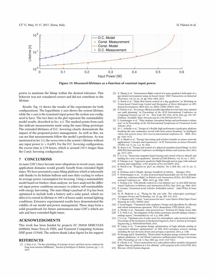
Constant Energy Harvesting. The blimp’s estimated lifetime,when the input energy was constant every time step, can be seenin Fig. 13. The lifetime when the rotor runs constantly is markedas ‘Const. Model’, and ‘D.C. Model’ is used to label duty cycling.Note that the �gure uses input power as the x-axis, so use that theperiod is 5.25 seconds to convert the power values to energy.
It should be noted that there is a vertical asymptote at x =0.198W, which is the point at which self sustainability is reached forD.C. hovering. Due to the increased power requirements of Const.hovering, this con�guration’s asymptote is located at x = 0.576W.
Probabilistic Energy Harvesting. To next scenario used was onethat approximates volatile lighting conditions, where the energyharvested follows a probabilistic distribution.
Before going into the results, we �rst need to comment on thede�nition of the lifetime, presented in (3). As stated in Section 4.1,the sustainability model provides us with the probability of thesystem being in a certain state after some time. Therefore, we needto de�ne a threshold ϵ , such that the system is de�ned not to workif the probability of the system being in the error state is larger thanϵ . As (3) shows, the lifetime is a function of the ϵ , so we estimatedthe lifetime using ϵ = 10−4. A lifetime with ϵ = 10−4 means that999 blimps out of a 1000 are estimated to be working after this time.We shall call this ϵ choice the pessimistic case.
The pessimistic case’s lifetime estimation is in�uenced by periodsthat harvest low amounts of energy, even though these cases happenless often. In Figure 12b, the relative di�erence between the averageand pessimistic lifetimes is shown. Recall that the absolute valuesfor these lifetimes can be seen in Fig. 13. What can be seen is thatthe pessimistic lifetime is estimated to be around 5% shorter thanthe lifetime when energy is added constantly, and this di�erenceincreases as the lifetime rises.
6.3 Experimental MeasurementsUsing the prototype’s speci�cation explained in Section 6.1, weevaluated our proposed power management techniques for nanoblimps. To this end, we use two con�gurations, one with constant
propulsion hovering (referred to as ‘Const.’) and another with dutycycling (referred to as ‘D.C.’). For each con�guration, we determinedhow di�erent input power levels a�ect the blimp’s lifetime.
Setup. Experiments with di�erent input powers were set up forboth con�gurations. The battery was initially charged for eachexperiment, and the blimp’s lifetime was recorded. The lifetime isde�ned as the point at which the rotors stop producing enough liftto keep the blimp within the desired ± 25 cm altitude window.
It should be noted that although the rotors continued to generatesome lift after that, the battery was unable to supply the necessary
0 0.1 0.2 0.3 0.4 0.5 0.6
Input Power [W]
0
0.05
0.1
0.15
Pro
babili
ty
(a) Harvested power distribution used in scenario
0 0.1 0.2 0.3 0.4 0.5 0.6
Mean Input Power [W]
0.8
0.85
0.9
0.95
1
Life
tim
e [
%]
Const. Model ( ǫ = 10-4
)
D.C. Model ( ǫ = 10-4
)
(b) Lifetimes for probabilistic harvesting, relative to constant har-vesting
Figure 12: Normalized lifetime results using the sustainabil-ity model and a scenario with variable input power
CF’17, May 15-17, 2017, Siena, Italy D. Palossi et al.
0 0.1 0.2 0.3 0.4 0.5 0.6
Input Power [W]
100
101
102
Lifetim
e [h]
D.C. Model
Const. Measurement
Const. Model
D.C. Measurement
Figure 13: Measured lifetimes as a function of constant input power.
power to maintain the blimp within the desired tolerance. Thisbehavior was not considered correct and did not contribute to thelifetime.
Results. Fig. 13 shows the results of the experiments for bothcon�gurations. The logarithmic y axis shows the system lifetime,while the x axis is the (constant) input power the system was con�g-ured to have. The two lines in the plot represent the sustainabilitymodel results, described in Sec. 6.2. The marked points from eachline indicate measurements made using the nano blimp prototype.The extended lifetimes of D.C. hovering clearly demonstrate theimpact of the proposed power management. As well as this, wecan see that measurements follow the model’s predictions. As wasmentioned in Sec 3.2, the excess time is the system’s lifetime withoutany input power (x = 0mW). For the D.C. hovering con�guration,the excess time is 3.78 hours, which is around 135 % longer thanthe Const. hovering con�guration.
7 CONCLUSIONSAs nano UAV’s have become more ubiquitous in recent years, manyapplication domains would greatly bene�t from extended �ighttimes. We have presented a nano blimp platform which is inherentlysafe thanks to its helium balloon and uses duty-cycling to reduceits average power consumption for hovering. Using a sustainabilitymodel based on Markov chain analysis, we have analyzed the di�er-ent input power conditions necessary to achieve self-sustainabilitywith energy harvesting. The nano blimp’s payload of 55 g has beenoptimized to include both a battery and a solar panel, which en-ables it to extend its lifetime to 100’s of hours under normal lightingconditions. Extensive experimental results have demonstrated thevalidity of our model and power management. These steps form asolid groundwork for future autonomous nano UAV’s which aresafe and have extended �ight times.
ACKNOWLEDGMENTSThis work has been funded by projects EC H2020 HERCULES(688860), Nano-Tera.ch YINS, and Transient Computing Systems(SNF grant 157048). The authors thank Lukas Sigrist for his support.
REFERENCES[1] J. Kim et al., “On the scheduling of systems of uavs and fuel service stations for
long-term mission ful�llment,” Journal of Intelligent & Robotic Systems, pp. 1–13,2013.
[2] X. Zhang et al., “Autonomous �ight control of a nano quadrotor helicopter in agps-denied environment using on-board vision,” IEEE Transactions on IndustrialElectronics, vol. 62, no. 10, pp. 6392–6403, 2015.
[3] A. Briod et al., “Optic-�ow based control of a 46g quadrotor,” in Workshop onVision-based Closed-Loop Control and Navigation of Micro Helicopters in GPS-denied Environments, IROS 2013, no. EPFL-CONF-189879, 2013.
[4] D. Palossi et al., “An energy-e�cient parallel algorithm for real-time near-optimaluav path planning,” in Proceedings of the ACM International Conference onComputing Frontiers, ser. CF ’16. New York, NY, USA: ACM, 2016, pp. 392–397.[Online]. Available: http://doi.acm.org/10.1145/2903150.2911712
[5] S. Leutenegger et al., “Solar airplane conceptual design and performance estima-tion,” in In Proceedings of the 3rd International Symposium on Unmanned AerialVehicles, 2010.
[6] M. C. Achtelik et al., “Design of a �exible high performance quadcopter platformbreaking the mav endurance record with laser power beaming,” in Intelligentrobots and systems (iros), 2011 ieee/rsj international conference on. IEEE, 2011,pp. 5166–5172.
[7] N. A. Bhatti et al., “Energy harvesting and wireless transfer in sensor networkapplications: Concepts and experiences,” ACM Transactions on Sensor Networks(TOSN), vol. 12, no. 3, p. 24, 2016.
[8] M. Burri et al., “Design and control of a spherical omnidirectional blimp,” in 2013IEEE/RSJ International Conference on Intelligent Robots and Systems, Nov 2013,pp. 1873–1879.
[9] P. Li et al., “Monocular snapshot-based sensing and control of hover, takeo�, andlanding for a low-cost quadrotor,” Journal of Field Robotics, vol. 32, no. 7, 2015.
[10] D. Falanga et al., “Aggressive quadrotor �ight through narrow gaps with onboardsensing and computing,” arXiv preprint arXiv:1612.00291, 2016.
[11] R. Wood et al., “Progress on ’pico’ air vehicles,” Int. J. Rob. Res., vol. 31, no. 11,2012.
[12] B. Siciliano and O. Khatib, Springer handbook of robotics. Springer, 2016.[13] P. Oettershagen et al., “A solar-powered hand-launchable uav for low-altitude
multi-day continuous �ight,” in Robotics and Automation (ICRA), 2015 IEEE Inter-national Conference on. IEEE, 2015, pp. 3986–3993.
[14] S. Verling et al., “Full attitude control of a vtol tailsitter uav,” in 2016 IEEE Interna-tional Conference on Robotics and Automation (ICRA), May 2016, pp. 3006–3012.
[15] R. Lozano, Unmanned aerial vehicles: Embedded control. John Wiley & Sons,2013.
[16] M. H. Shaheed et al., “Flying by the sun only: The solarcopter prototype,”Aerospace Science and Technology, vol. 45, pp. 209–214, 2015.
[17] T. J. Nugent and J. T. Kare, “Laser power for uavs,” Laser MotiveWhite Paper-PowerBeaming for UAVs, NWEN, 2010.
[18] S. Leutenegger, “Unmanned solar airplanes: Design and algorithms for e�cientand robust autonomous operation,” Ph.D. dissertation, ETH-Zürich, 2014.
[19] A. Weider et al., “Sunsailor: solar powered uav,” Technion IIT, Haifa, Israel, 2006.[20] T. E. Noll et al., “Investigation of the helios prototype aircraft mishap volume i
mishap report,” Downloaded on, vol. 9, p. 2004, 2004.[21] J. Li et al., “Optimum area of solar array for stratospheric solar-powered airship,”
Proceedings of the Institution of Mechanical Engineers, Part G: Journal of AerospaceEngineering, p. 0954410016670420, 2016.
[22] H. Liang et al., “Conceptual design optimization of high altitude airship inconcurrent subspace optimization,” in 50th AIAA aerospace sciences meetingincluding the new horizons forum and aerospace exposition, 2012, p. 1180.
[23] W. Knaupp and E. Mundschau, “Photovoltaic-hydrogen energy systems for strato-spheric platforms,” in 3rd World Conference onPhotovoltaic Energy Conversion,2003. Proceedings of, vol. 3, May 2003, pp. 2143–2147 Vol.3.
[24] K. Ghosh et al., “Power generation on a solar photovoltaic modules integratedlighter-than-air platform at a low altitude,” arXiv preprint arXiv:1610.07598, 2016.
[25] Bitcraze. (2016) System diagram.


![MQP Report Quadrotor Final[1]](https://static.fdocuments.in/doc/165x107/54362771219acdd95f8b5088/mqp-report-quadrotor-final1.jpg)