Self Powered Wind Sensor - Electrical engineeringelec499/2005b/group12/Projectreport_R1.pdf · ELEC...
25
University of Victoria Faculty of Engineering ELEC 499b Project Report Self Powered Wind Sensor http://web.uvic.ca/~darrenm/bss2home.htm April 08 th , 2005 In partial fulfillment of the requirements of the ELEC 499 Course Student’s Approval I approve the release of this report to the University of Victoria for evaluation purposes only. The report is to be considered: NOT CONFIDENTIAL CONFIDENTIAL Name Signature Date Paul Leslie Jean-Francois Jobidon Darren McElhinney If a report is deemed CONFIDENTIAL, a non-disclosure form signed by an evaluator will be faxed to the employer. The report will be destroyed following evaluation. If the report is NOT CONFIDENTIAL, it will be returned to the student following evaluation.
Transcript of Self Powered Wind Sensor - Electrical engineeringelec499/2005b/group12/Projectreport_R1.pdf · ELEC...
University of Victoria Faculty of Engineering
ELEC 499b Project Report
Self Powered Wind Sensor http://web.uvic.ca/~darrenm/bss2home.htm
April 08th, 2005 In partial fulfillment of the requirements of the
ELEC 499 Course
Student’s Approval I approve the release of this report to the University of Victoria for evaluation purposes only.
The report is to be considered:
NOT CONFIDENTIAL CONFIDENTIAL Name Signature Date
Paul Leslie
Jean-Francois Jobidon
Darren McElhinney
If a report is deemed CONFIDENTIAL, a non-disclosure form signed by an evaluator will be faxed to the employer. The report will be destroyed following evaluation. If the report is NOT CONFIDENTIAL, it will be returned to the student following evaluation.

University of Victoria Faculty of Engineering ELEC 499 Project Report
Self Powered Wind Sensor BSS2
Page 1
Summary BSS2 was given the challenge of producing a self-powered wind sensor by AXYS Environmental Systems. The idea behind making the sensor wireless was to eliminate power cables that from the base unit on the ground up to the sensor wherever it was located. After testing the sensor it was recognized that it simply couldn’t produce sufficient power. In order to maintain the “self-powered” concept BSS2 decided to use solar power as it will make the unit wireless and completely isolated from external systems. After receiving approval from AXYS, BSS2 immediately started investigating solar power as an alternate means. We began by purchasing a battery and from then everything fell into place as all the other components depend on the selection of the battery. After completing and design the circuit was built and tested to be up to our expectations. Since the circuit was working correctly with no flaws, the circuit was then to be set into a PCB. BSS2 used Camosun College's facilities to design, build and test the PCB, which unfortunately could not be made function correctly in time for the demo. Since the board is physically small (6cm x 3cm), it was difficult to troubleshoot and BSS2 had to use the breadboard for their project demonstration. This was not a big deal as the board was merely a prototype. The project demonstration day went well as the AXYS sponsor came out and was impressed with the results. Overall the project was a great learning experience as there was a lot of material in regards to charging systems and battery chemistries pros and cons that we didn’t know.

University of Victoria Faculty of Engineering ELEC 499 Project Report
Self Powered Wind Sensor BSS2
Page 2
Figure 1 System Schematic
University of Victoria Faculty of Engineering ELEC 499 Project Report
Self Powered Wind Sensor BSS2
TOC - 1
TABLE OF CONTENTS PAGE
1. INTRODUCTION.......................................................................................... 1
1.1 Objective................................................................................................ 1
2. DESIGN PROCEDURES ............................................................................. 2
2.1 Wind Sensor Test Results .................................................................... 2 2.2 Circuit Theory and Operation............................................................... 3 2.3 Components .......................................................................................... 5
2.3.1. Storage Device ........................................................................... 5 2.3.2. Charging Chip............................................................................. 7 2.3.3. Voltage Regulator....................................................................... 8 2.3.4. Charge Pumps .......................................................................... 10
3. TEST PROCEDURES AND ASSEMBLY RESULTS................................. 11
3.1 Testing ................................................................................................. 11
4. ASSEMBLY RESULTS.............................................................................. 12
5. DISCUSSION ............................................................................................. 18
5.1 Deviations from Original Specifications ........................................... 18 5.2 Future Improvements.......................................................................... 19 5.3 Pitfalls and Problems.......................................................................... 19
6. CONCLUSION ........................................................................................... 20
7. REFERENCES........................................................................................... 20
8. APPENDICES ............................................................................................ 21

University of Victoria Faculty of Engineering ELEC 499 Project Report
Self Powered Wind Sensor BSS2
Page 1
1. INTRODUCTION BSS2 met with Axys Environmental Systems at the beginning of the project to discuss the Self Powered Wind Sensor project. At this meeting, AXYS made it clear to BSS2 that the project may not be possible to complete, as the sensor had never been tested before for this purpose. BSS2 however looked at this as being a challenge and a first time occurrence, and accepted the project hoping that the sensor would supply adequate power, but knowing that they could use Solar Power as a back up plan.
1.1 OBJECTIVE To determine if the RM young model 05103 wind sensor has the capability of generating enough power from its internal system to become a self powered unit. If it has, then a charge storage device capable of storing enough power to run the microprocessor, potentiometer, and transceiver circuits for a specific period of time will be introduced. To accommodate the storage device, a charging and switching circuit will be designed to absorb as much energy from the power source while being as efficient as possible. The following specifications were given from AXYS to try to adhere to. It was explained at the meeting though that some of the specifications were “wishful thinking”. The specifications were as follows; • Self powered Operating Input Voltage off +5 Vdc - -5Vdc • Low Power Consumption (<10mA) • Packaged inside the RM Young Interface Box (~ 2”x1”x 1.2”) • Low production costs (<$25/unit) If the sensor does not have the capabilities to power itself, then other means of power will be investigated.

University of Victoria Faculty of Engineering ELEC 499 Project Report
Self Powered Wind Sensor BSS2
Page 2
2. DESIGN PROCEDURES 2.1 WIND SENSOR TEST RESULTS
The RM Young wind sensor has a 6-pole magnet located in its head unit. The magnet is not directly coupled to the coil though, as a normal generator would be. Instead the coil is placed orthogonal to the magnet. This design is used to reduce loading on the generator during sampling, which would affect the accuracy of the sensor as it would slow down as more load was introduced. The internal impedance of the sensor was 2000 ohms and to achieve maximum power transfer the load impedance has to equal the input impedance. A resistance of 2000 ohms was connected across the output of the generator and the following figure shows the power to wind speed relationship for average speed of wind in the Victoria region. The windsensor turning at 3000RPM is approximately 53km/hr windspeed.
Figure 2 Sensor Testing Results Unfortunately the positioning of the coil was solely the reason behind the sensor not being able to generate enough power to run the necessary components, therefore an alternate form of energy had to be used, as AXYS strictly said that the sensor could not be altered. Based on Industry standards, the most popular type of power supplied to wind sensors to be self-powered is Solar Power, therefore solar power will be used for this project.
University of Victoria Faculty of Engineering ELEC 499 Project Report
Self Powered Wind Sensor BSS2
Page 3
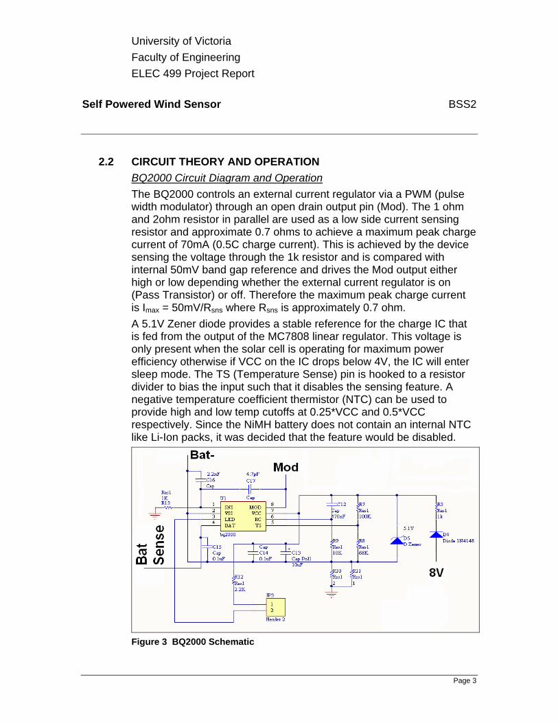
2.2 CIRCUIT THEORY AND OPERATION BQ2000 Circuit Diagram and Operation The BQ2000 controls an external current regulator via a PWM (pulse width modulator) through an open drain output pin (Mod). The 1 ohm and 2ohm resistor in parallel are used as a low side current sensing resistor and approximate 0.7 ohms to achieve a maximum peak charge current of 70mA (0.5C charge current). This is achieved by the device sensing the voltage through the 1k resistor and is compared with internal 50mV band gap reference and drives the Mod output either high or low depending whether the external current regulator is on (Pass Transistor) or off. Therefore the maximum peak charge current is Imax = 50mV/Rsns where Rsns is approximately 0.7 ohm. A 5.1V Zener diode provides a stable reference for the charge IC that is fed from the output of the MC7808 linear regulator. This voltage is only present when the solar cell is operating for maximum power efficiency otherwise if VCC on the IC drops below 4V, the IC will enter sleep mode. The TS (Temperature Sense) pin is hooked to a resistor divider to bias the input such that it disables the sensing feature. A negative temperature coefficient thermistor (NTC) can be used to provide high and low temp cutoffs at 0.25*VCC and 0.5*VCC respectively. Since the NiMH battery does not contain an internal NTC like Li-Ion packs, it was decided that the feature would be disabled.
Figure 3 BQ2000 Schematic
University of Victoria Faculty of Engineering ELEC 499 Project Report
Self Powered Wind Sensor BSS2
Page 4
In the schematic shown above in Figure 3, capacitor C12 and resistor R9 generate the RC circuit required to feed the internal system clock. These components values play the most important role in designing a charge system with the BQ2000. The maximum charge time is set by these components and the capacitor size determines if a top-off option will be used for NiMH batteries to maximize battery capacity. To enable this option the value of the cap must be greater than 0.13uF and the value or the resistor must be less than 15k. The max charge time is set as MTO = Rmto*Cmto*35988 where Rmto is in ohms, Cmto in Farads and MTO in minutes. The BQ2000 trickle charges at a 1 Hz rate and the pulse width is user selectable by the Rmto resistor value. The BQ2000 also trickle charges a battery if the cell voltage falls below 950mV to revive deeply discharged batteries before entering the fast charge state. The BQ2000 has an active low LED pin that turns a LED on by sinking current into the chip. The LED blinks at a 1 Hz rate for the pre-Fast charge trickle charge for depleted batteries and if there is a temperature fault. It stays continually lit during the fast charge cycle. The output goes into high impedance for the top-off and post-fast charge trickle charge states or when there is no battery present. Current Regulator Diagram and Operation The circuit shown below in figure 4 is a current regulator. It consists of a PNP transistor Q3 which is driven into saturation and cut-off modes via the NPN transistor Q2 which is driven by the Mod output from the BQ2000. Q2 operates in the linear region and Q1 is used for current limiting. The input diode D1 ensures current does not flow back into the 8V regulator and the solar cell when the regulator is off. When Q3 is on the capacitors across the battery charge up and then the transistor turns off and the inductor tries to maintain current flow which cause the caps to discharge through the low side current sense resistors back up through the Shottky diode (known as the freewheeling diode) and back thru the inductor. A resistor divider is used to drop the voltage of the multi-cell battery to the voltage of a single cell so that the charge IC can perform the correct algorithm. The input impedance to the resistor divider must be between 200k - 1M ohms. A 100k potentiometer is used to correct for the resistor tolerances and ensure a proper divide by 3 ratio.

University of Victoria Faculty of Engineering ELEC 499 Project Report
Self Powered Wind Sensor BSS2
Page 5
Figure 4 Current Regulator Schematic For a drawing of the complete circuit with all the components tied together see figure 1.
2.3 COMPONENTS The majority of our components were obtained from Texas Instruments, as they were helpful, cooperative and fast in shipping. The outline of a charging circuit was obtained, and we had to go through the circuit and determine what was doing what, and what could be eliminated. The components were sized differently as well as the parameters change depending on the size and type of battery being charged. 2.3.1. STORAGE DEVICE
BSS2 investigated numerous different types of storage devices, as they all have their pro’s and con’s. Supercapacitors are cheap and they work in extreme ambients almost as well as they do in normal ambients. They are cheaper than batteries, and have a quicker recharge time. Their major downfall is that they discharge much quicker than a

University of Victoria Faculty of Engineering ELEC 499 Project Report
Self Powered Wind Sensor BSS2
Page 6
battery, and to obtain the same storage capabilities the supercapacitor is physically much bigger than a battery. Lithium Ion batteries are the best in the battery family. They have the quickest recharge time, and they can hold charge the longest. Lithium Ion batteries must not be operated below their lower operating voltage of 1.8V, and because oft this reason a person cannot simply go to the store and purchase a Lithium Ion battery for personal use. If we used a Lithium Ion battery, we would have had to send our charging circuit away to get approved. These batteries are also the most expensive on the market. They can handle between 500-700 complete recharges (for the rating of battery we need). Nickel Metal Hydride (NiMH) batteries are much cheaper than Lithium Ion. Advances have been made with these batteries, as they have eliminated the memory problems. If these batteries were constantly charged after only being half discharged then they would loose their full charge capability and only be able to store half of the original charge. These batteries can handle between 500-700 complete recharges (for the rating of battery we need). The last type of battery investigated was Nickel Cadmium (NiCd). Out of all rechargable batteries these have the poorest performance and are the cheapest. They have the memory problems mentioned above for NiMH batteries, and because of this, they can only be recharged between 300-400 times (for the rating of battery we need). BSS2 decided to go with the NiMH battery because essentially the charging circuit that was built can accommodate both NiMH batteries and Lithion Ion. It was decided that NiCd would never be used simply because of their poor performance. Supercapacitors were not chosen as they are physically too big and we were limited to size. None of the batteries investigated were capable of the ambients that AXYS required however a military grade battery could be purchased which would cover a much wider range of temperature. These batteries are very expensive and outside the budget of BSS2. Again though the charging circuit produced could charge military grade batteries. For a picture and data sheet for the battery, see appendix 1.

University of Victoria Faculty of Engineering ELEC 499 Project Report
Self Powered Wind Sensor BSS2
Page 7
2.3.2. CHARGING CHIP One of the major components of the system is the BQ2000, a charge management integrated circuit (IC) from Texas Instruments. It is a multi-chemistry IC that controls the fast charge and trickle rates for NiMH, NiCd, and Li-Ion cells and has a built in battery insertion/removal detection system. It determines which battery chemistry is present because Li-Ion batteries rise to a max cell voltage (MCV) of 2V, while a NiMH or NiCd will not rise to this level. The IC then proceeds to charge the battery with the associated algorithms shown in the figure below.
Figure 5 Battery Chemistry Charge Algorithms The diagram below in figure 6 shows the overall general blocks that are incorporated in the BQ2000 design. The RC input feeds an oscillator circuit for the system clock while the bat pin is sent to an ADC for comparison in the ALU to the band gap reference voltages provided on-chip. Voltage comparators are used to compare the allowable operating temperature ranges through an external resistor divider as well as the battery voltage to the on-chip reference voltages. The sense input is used to sense current through either a high or low side current sense resistor. To see a datasheet for the BQ2000, see appendix 2.

University of Victoria Faculty of Engineering ELEC 499 Project Report
Self Powered Wind Sensor BSS2
Page 8
Figure 6 Block Diagram of BQ2000
2.3.3. VOLTAGE REGULATOR MC7808 The three terminal MC7808 linear voltage regulator is used to provide a fixed 8 V to the main circuit from the solar panel. As long as the solar cell is providing 8V to 30V, the regulator will be able to provide the necessary voltage for the charging system. Below 8V will limit the current for the charging the battery and eventually below 4V will put the BQ2000 in sleep mode as the this will not be enough voltage for the chip to function. Two external capacitors (0.33 uF and 0.1uF) are used to reduce noise with the device. The MC7808 can operate from 0o C to 125o C with current up to 1A. See appendix 3 for the datasheet.
Figure 7 8V Linear Voltage Regulator

University of Victoria Faculty of Engineering ELEC 499 Project Report
Self Powered Wind Sensor BSS2
Page 9
3.3 reg 101 The REG101-33 low dropout linear regulator was used to regulate the voltage to a fixed 3.3 V for the required CMOS standard. This integrated circuit from Texas Instruments came in a 5 pin SOT-23 package type which allows more room on the PCB than a DIP. This regulator was chosen for the low amount of pins and low noise configuration and the abillity to operate without an output capacitor. The Reg101-33 produces only 29µVrms in the 10 Hz to 100 kHz band. The noise can further be reduced by a factor of 2.8 if a 10nF noise reduction capacitor is used on the noise reduction pin. The IC has a TTL-CMOS compatible enable pin and any voltage under 0.5V will turn the device off and drops the IC current to the rest current of 10nA. Only one external 0.1uF capacitor is needed for proper operation and is placed at the input for proper analog design purposes. The REG101 supplies a max current of 100 mA and will drop no more than 60mV at full load and operates in temperatures ranging from -40o C to 85o C. Below figure 8 shows the configuration of REG101-33. The regulator is thermally protected (160 ºC) and utilizes an overcurrent protection including a foldback current limit. To see a data sheet for this regulator see appendix 4.
(1) Cout is optional
Figure 8 Low Dropout Linear Voltage Regulator

University of Victoria Faculty of Engineering ELEC 499 Project Report
Self Powered Wind Sensor BSS2
Page 10
2.3.4. CHARGE PUMPS TPS 60132 In addition to the using linear regulators, the TPS60132 charge pump from Texas Instruments was used to step up the battery voltage from 3.6 V to a fixed 5 V output. The package type for the IC was a 20 pin HTSSOP. Four external capacitors with low ESR (Equivalent Series Resistance) are needed for the device to have low noise and low output ripple as shown in figure 9 below. The two flying 2.2 uF capacitors are extremely important as they allow proper step up operation of the circuit. A power saving pulse skip mode and a low battery comparator are configuration options built into this I.C. This device was specifically chosen for working with a 3 cell NiMH/alkaline or 1 cell lithium ion battery. The I.C. can either multiply the input voltage by 1.5 or 2 depending on input voltage and load current. The TPS 60132 has a TTL-CMOS compatible enable pin which drops the maximum sleep current to 1uA and has an undervoltage lockout when the input drops below 1.6V. The TPS 60132 can allow a max output current 0f 150 mA and can operate in the temperature ranges of -55o C to 150o C. Figure 9 shows the typical configuration of the TPS 60132 charge pump. To see a data sheet for this component see appendix 5.
Figure 9 TPS60132 Charge Pump

University of Victoria Faculty of Engineering ELEC 499 Project Report
Self Powered Wind Sensor BSS2
Page 11
TPS 60400 The TPS 60400 is a charge pump inverter that was used from Texas Instruments. Its function is to invert the regulated 5 V output from the TPS 60132 to -5 V. The package type is a SOT-23 with only 5 pins. Only 3 external 1µF capacitors are required for the charge pump inverter. The charge pump inverter has a quiescent current of only 210µA with no load below 60ºC. This device was chosen for its low noise and low pin configuration and has a built in Schottky diode for start up under load conditions. The I.C. can operate in optimum temperature ranges of -55o C to 150o C at a maximum of 60 mA. Figure 10 show the TPS 60400 configuration used. To see a data sheet for this component see appendix 6.
Figure 10 TPS60040 Charge Pump Inverter 3. TEST PROCEDURES AND ASSEMBLY RESULTS
3.1 TESTING Circuitry functionality testing was performed on the breadboard, as it was a stright forward process to test all the regulators and charge pumps etc. All that has to be done is simply apply an input voltage or current and measure the corresponding output. Once the battery was introduced into the system, the charging chip was tested and made sure that it was doing everything it should have been doing. This confirmation was done with an ammeter and an LED. The most testing however went into trying to get the PCB working. It’s very difficult to troubleshoot a PCB, especially one with the dimensions

University of Victoria Faculty of Engineering ELEC 499 Project Report
Self Powered Wind Sensor BSS2
Page 12
we used. All that can be tested with a PCB this small is testing all the solder connections and make sure that nothing is shorted to another component or ground plane. We believe that the problem with our board is a trace that is shorted to another trace, or one of the chips wasn’t working correctly. Since the soldering was performed under a magnifying glass, it was very difficult trying to find it, and the conclusion was that we know the circuit works, and if AXYS wants to develop another board then they can send it away to be professionally done. The one we developed is just a prototype showing layout.
4. ASSEMBLY RESULTS Protel PCB design The schematic for the project was created with Protel DXP which has the capability to convert schematics to PCB layouts. The figure below displays the top layer of the PCB. The component outlines are shown in yellow and are various different types of packages including surface mount.
Figure 11 Top Layer PCB
University of Victoria Faculty of Engineering ELEC 499 Project Report
Self Powered Wind Sensor BSS2
Page 13
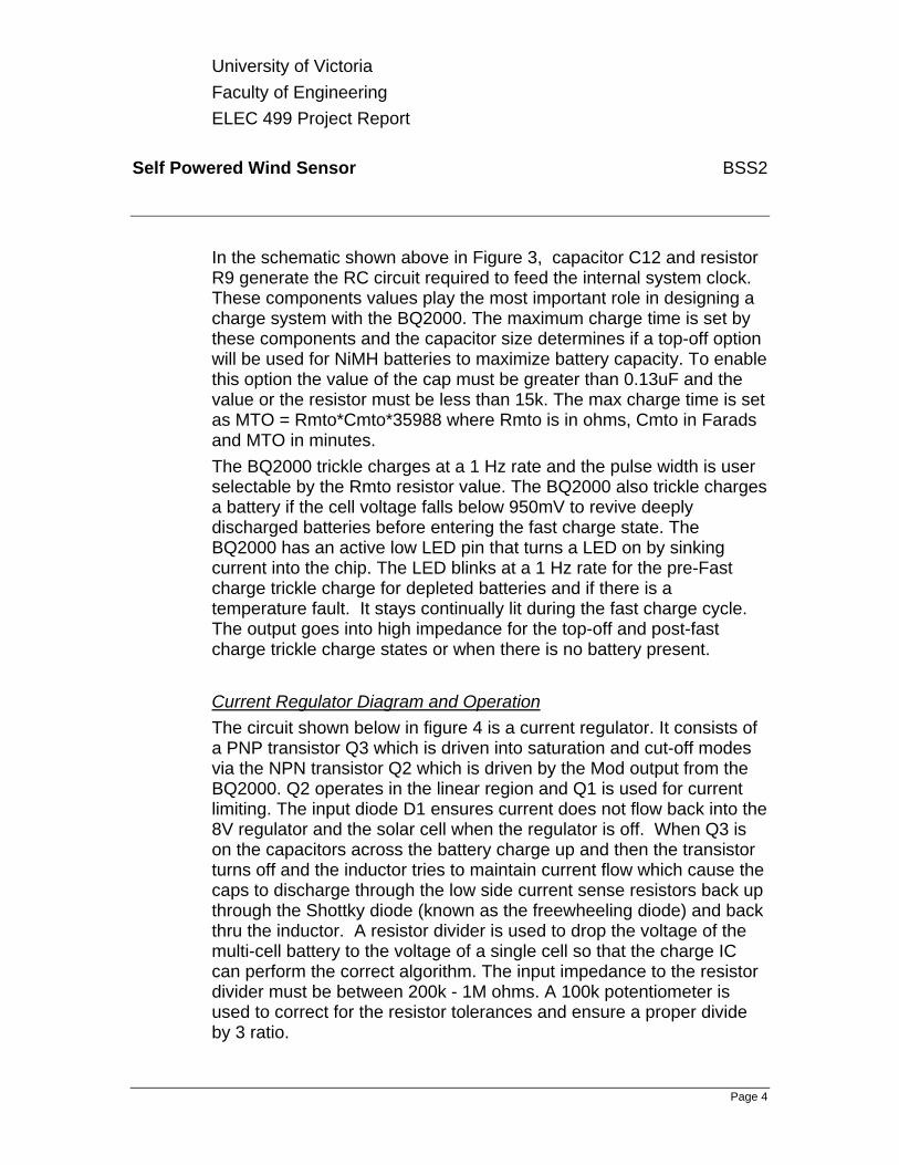
The figure below displays the bottom layer of the PCB. The footprints for the IC's were created from the datasheets to ensure the IC's would have the correct size pads and dimensions on the PCB (U1, U3 and U5). The bottom layer is seen looking down from the top view.
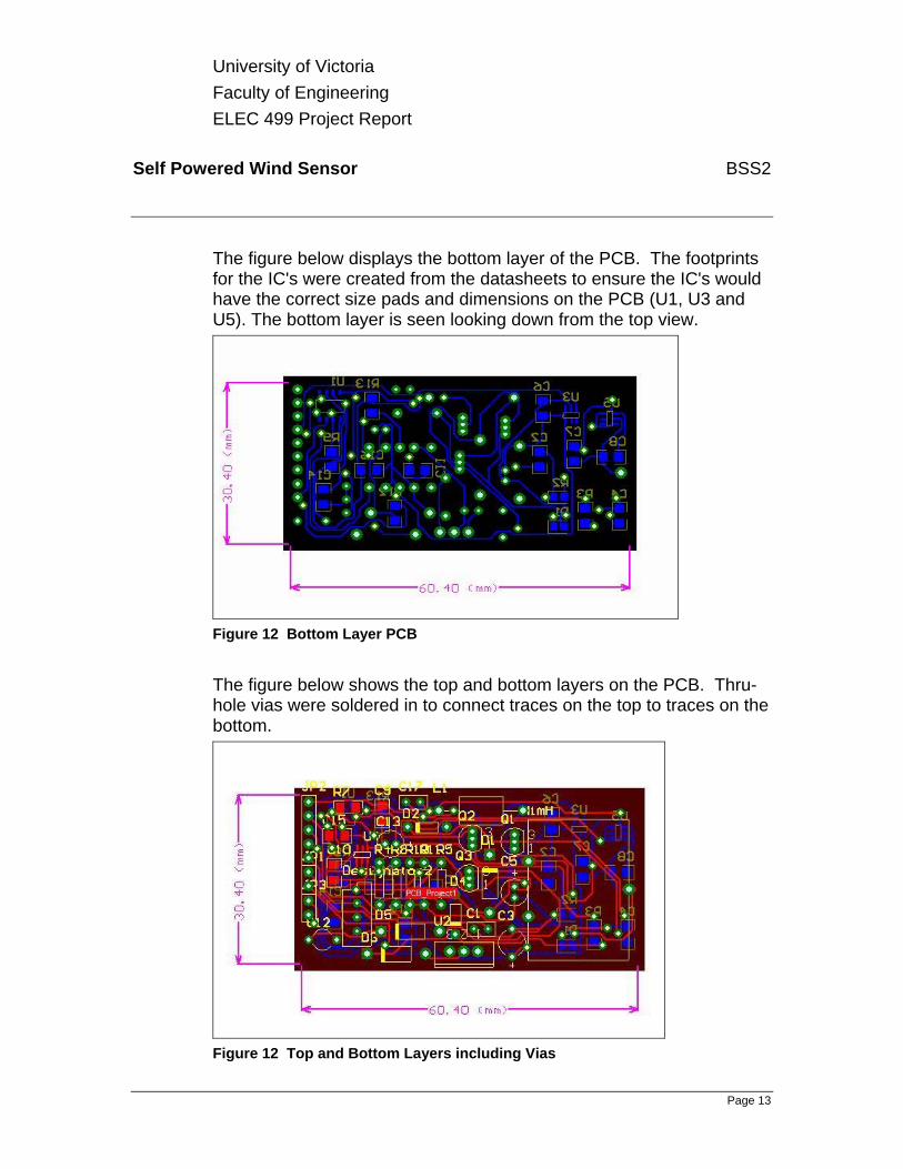
Figure 12 Bottom Layer PCB The figure below shows the top and bottom layers on the PCB. Thru-hole vias were soldered in to connect traces on the top to traces on the bottom.
Figure 12 Top and Bottom Layers including Vias
University of Victoria Faculty of Engineering ELEC 499 Project Report
Self Powered Wind Sensor BSS2
Page 14
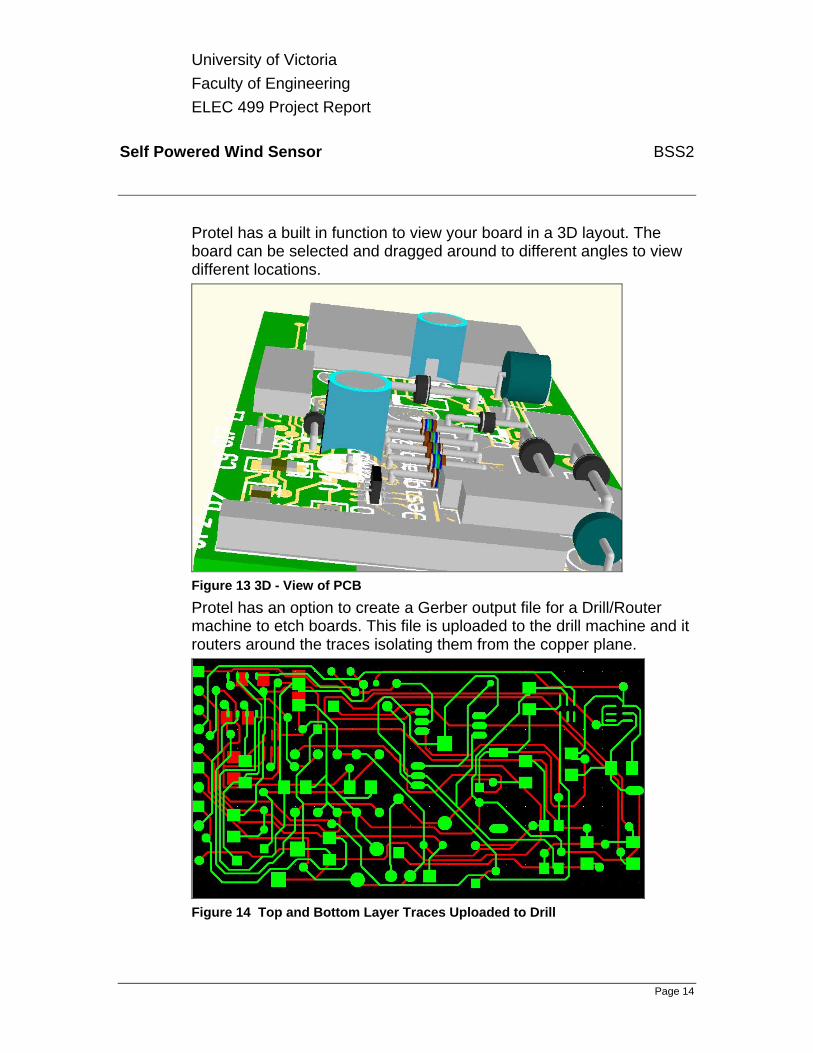
Protel has a built in function to view your board in a 3D layout. The board can be selected and dragged around to different angles to view different locations.
Figure 13 3D - View of PCB Protel has an option to create a Gerber output file for a Drill/Router machine to etch boards. This file is uploaded to the drill machine and it routers around the traces isolating them from the copper plane.
Figure 14 Top and Bottom Layer Traces Uploaded to Drill
University of Victoria Faculty of Engineering ELEC 499 Project Report
Self Powered Wind Sensor BSS2
Page 15
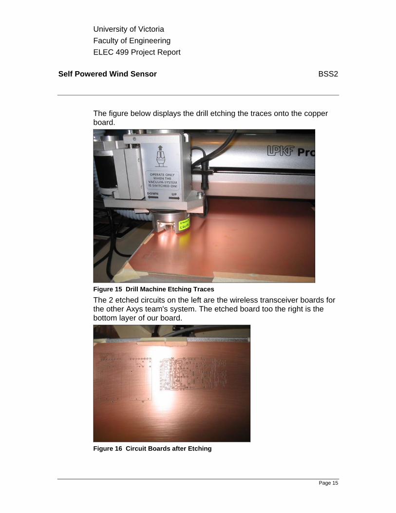
The figure below displays the drill etching the traces onto the copper board.
Figure 15 Drill Machine Etching Traces The 2 etched circuits on the left are the wireless transceiver boards for the other Axys team's system. The etched board too the right is the bottom layer of our board.
Figure 16 Circuit Boards after Etching
University of Victoria Faculty of Engineering ELEC 499 Project Report
Self Powered Wind Sensor BSS2
Page 16
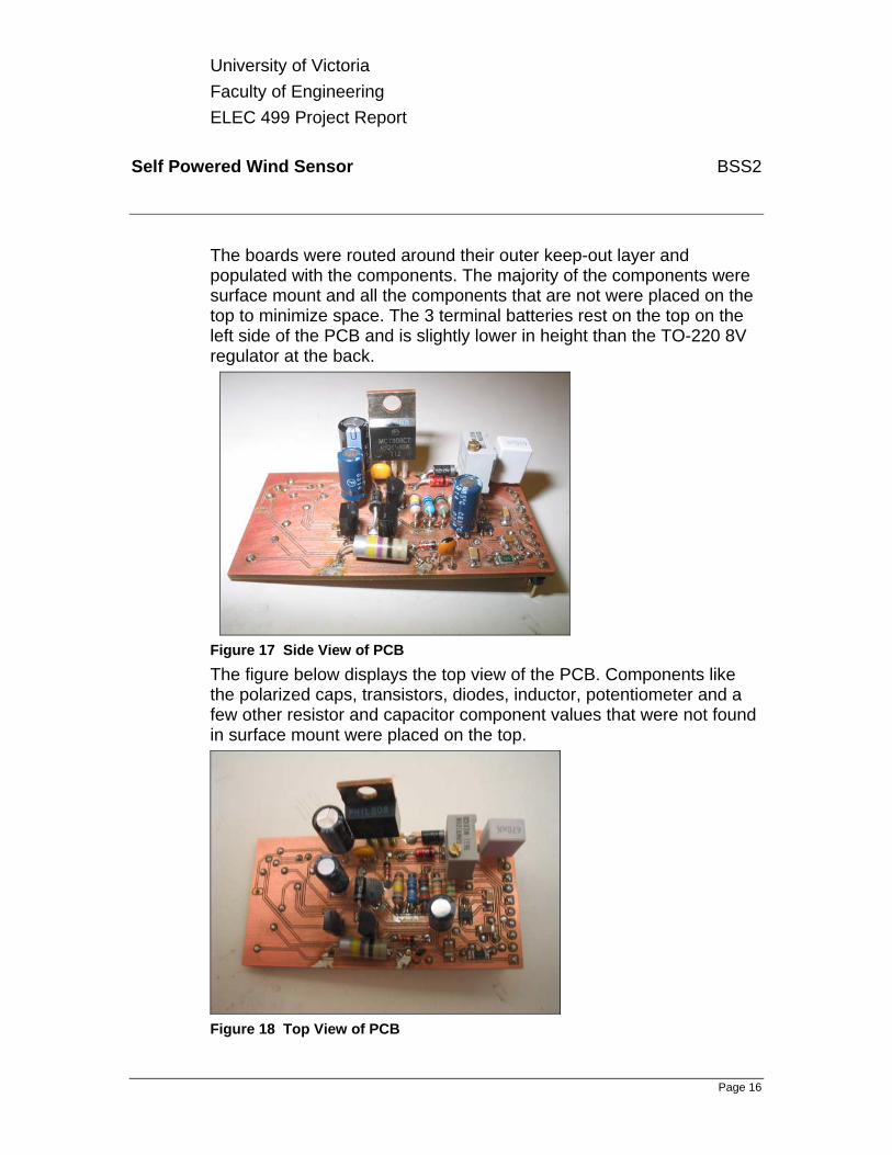
The boards were routed around their outer keep-out layer and populated with the components. The majority of the components were surface mount and all the components that are not were placed on the top to minimize space. The 3 terminal batteries rest on the top on the left side of the PCB and is slightly lower in height than the TO-220 8V regulator at the back.
Figure 17 Side View of PCB The figure below displays the top view of the PCB. Components like the polarized caps, transistors, diodes, inductor, potentiometer and a few other resistor and capacitor component values that were not found in surface mount were placed on the top.
Figure 18 Top View of PCB
University of Victoria Faculty of Engineering ELEC 499 Project Report
Self Powered Wind Sensor BSS2
Page 17
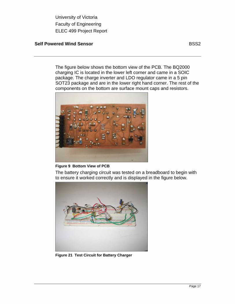
The figure below shows the bottom view of the PCB. The BQ2000 charging IC is located in the lower left corner and came in a SOIC package. The charge inverter and LDO regulator came in a 5 pin SOT23 package and are in the lower right hand corner. The rest of the components on the bottom are surface mount caps and resistors.
Figure 9 Bottom View of PCB The battery charging circuit was tested on a breadboard to begin with to ensure it worked correctly and is displayed in the figure below.
Figure 21 Test Circuit for Battery Charger

University of Victoria Faculty of Engineering ELEC 499 Project Report
Self Powered Wind Sensor BSS2
Page 18
On April 1, 2005, team BSS2 demoed the project in the Engineering building along with the other ELEC 499 projects. The solar cell is in the picture below along with the website, the breadboard circuit as well as the PCB.
Figure 22 Final setup for Project Demo
5. DISCUSSION 5.1 DEVIATIONS FROM ORIGINAL SPECIFICATIONS
The most significant deviation from the original specification outlined by AXYS, was using solar power instead of the sensor generated power. The deviation was unavoidable and accepted by AXYS. The ambient range expected by AXYS covered quite a wide range of temperature. To obtain an average battery to cover such temperatures is military grade and very expensive. Any NiMH battery can replace the one we used, therefore we simply used an average battery from battery world. The charging circuit is good down to –20 degrees Celcius although it is recomended to charge above 0 degrees. If a temperature below this is required batteries and components tend to get very expensive and into military grade material. If the size of the box was bigger, supercapacitors could have been used, and then the required temperature could have been achieved. BSS2 felt however that it was more important to adhere to the physical size requirements as that was something emphasized by AXYS.

University of Victoria Faculty of Engineering ELEC 499 Project Report
Self Powered Wind Sensor BSS2
Page 19
5.2 FUTURE IMPROVEMENTS Many future improvements can be done to improve the overall project. A few resistors and capacitors used for the project were not available for surface mount during the time frame. These components ended up taking up much room on the PCB. Only surface mount resistor and capacitors should be used to reduce the space needed on the PCB. This could reduce the dimensions of the PCB and possibly reduce the cost of components. Soldering surface mount components is also a much simpler process than working with axial resistors or radial capacitors. The three cell NiMH battery size may also need improvement, as it uses the most room on the PCB. A new battery with smaller dimensions could greatly reduce the space needed on the PCB. The PCB must fit into the RM Young sensor box, as well as two others boards from group 11( the other Axys team). To ensure that all the boards fit properly, a larger box could be used, or a multilayered board could be used instead of a dual layer board. This would minimize the space needed by combining all the circuitry from both groups (project 11 & 12) onto one board. This would also simplify the interface between the circuits of each group.
5.3 PITFALLS AND PROBLEMS One of the most significant problems for this project was the wind sensor’s inability to generate sufficient power from the original plan. Much time on the project was spent on extensive testing of the device to ensure our results. After several meeting with Dr. S Nandi, it was determined that it was not possible to obtain the necessary power without modifying the device itself. Much time was spent again to change the specifications to use a solar panel instead and to get a new plan approved. Another pitfall was the fact that most of the obtained chips were in TSSOP or SOT packages. Therefore testing the voltage regulators and charge pumps was nearly impossible on a regular breadboard. After discussing this with the electronic technicians, breakboard were ordered to remedy the situation as other groups had similar problems as well. However the recieved breakboards where designed for SOIC

University of Victoria Faculty of Engineering ELEC 499 Project Report
Self Powered Wind Sensor BSS2
Page 20
package type which made it much harder to solder the TSSOP and SOT voltage regulators and charge pumps for testing purposes.
6. CONCLUSION This project went very well but there were a few obstacles that were eventually overcome. We spent a great deal of time trying to find something that would allow us to use the sensor to generate its own power as we really had high hopes of making it work. We ended up leaving not much time to complete the project and we cut it close a few times trying to adhere to the deadlines involved with getting this project completed. We spent a lot of time performing research and we didn’t really want to do a project solely on charging a battery as we thought it would be simple. After getting underway with the battery charger we realized that there was a lot more complex than any of us thought. There current regulator part of the charging system was simulated in MicroCap to ensure the circuit was working the way we figured. Everything from the battery used to the charging chip selection required a lot of research to be completed. It was a great learning experience Our sponsor AXYS Environmental Systems was happy with what we developed and provided for them, so BSS2 is in turn happy with their project results as we did a good job.
7. REFERENCES 1. www.batteryuniversity.com 2. www.texasinstruments.com

University of Victoria Faculty of Engineering ELEC 499 Project Report
Self Powered Wind Sensor BSS2
Page 21
8. APPENDICES 1. Varda NiMH battery datasheet 2. TI BQ2000 Multi-Chemistry Battery Charging IC datasheet 3. MC7808 Linear 8V Regulator 4. TI REG101-33 Low Drop-Out Voltage Regulator datasheet 5. TI TPS 60132 Boost Charge Pump datasheet 6. TI TPS 60400 Charge Pump Inverter datasheet