Self-Organizing Software Architectures
125
Department of Computer Science Series of Publications A Report A-2013-13 Self-Organizing Software Architectures Pietu Pohjalainen To be presented, with the permission of the Faculty of Science of the University of Helsinki, for public criticism in Auditorium XV, University Main Building, on 13th December 2013, at noon. University of Helsinki Finland
Transcript of Self-Organizing Software Architectures

Department of Computer ScienceSeries of Publications A
Report A-2013-13
Self-Organizing Software Architectures
Pietu Pohjalainen
To be presented, with the permission of the Faculty of Scienceof the University of Helsinki, for public criticism in AuditoriumXV, University Main Building, on 13th December 2013, at noon.
University of HelsinkiFinland

SupervisorsJukka Paakki, University of Helsinki, FinlandJuha Taina, University of Helsinki, Finland
Pre-examinersGorel Hedin, Lund University, SwedenJyrki Nummenmaa, University of Tampere, Finland
OpponentKai Koskimies, Tampere University of Technology, Finland
CustosJukka Paakki, University of Helsinki, Finland
Contact information
Department of Computer ScienceP.O. Box 68 (Gustaf Hallstromin katu 2b)FI-00014 University of HelsinkiFinland
Email address: [email protected]: http://www.cs.helsinki.fi/Telephone: +358 9 1911, telefax: +358 9 191 51120
Copyright © 2013 Pietu PohjalainenISSN 1238-8645ISBN 978-952-10-9424-8 (paperback)ISBN 978-952-10-9425-5 (PDF)Computing Reviews (1998) Classification: D.2.11, D.1.2, D1.5, D.2.2,D.2.3, D.2.7, D.2.13Helsinki 2013Unigrafia

Self-Organizing Software Architectures
Pietu Pohjalainen
Department of Computer ScienceP.O. Box 68, FI-00014 University of Helsinki, [email protected]
PhD Thesis, Series of Publications A, Report A-2013-13Helsinki, December 2013, 114 + 71 pagesISSN 1238-8645ISBN 978-952-10-9424-8 (paperback)ISBN 978-952-10-9425-5 (PDF)
Abstract
Looking at engineering productivity is a source for improving the state ofsoftware engineering. We present two approaches to improve productivity:bottom-up modeling and self-configuring software components. Produc-tivity, as measured in the ability to produce correctly working softwarefeatures using limited resources is improved by performing less wasteful ac-tivities and by concentrating on the required activities to build sustainablesoftware development organizations.
Bottom-up modeling is a way to combine improved productivity with agilesoftware engineering. Instead of focusing on tools and up-front planning,the models used emerge, as the requirements to the product are unveiledduring a project. The idea is to build the modeling formalisms strongenough to be employed in code generation and as runtime models. Thisbrings the benefits of model-driven engineering to agile projects, where thebenefits have been rare.
Self-configuring components are a development of bottom-up modeling.The notion of a source model is extended to incorporate the software enti-ties themselves. Using computational reflection and introspection, depen-dent components of the software can be automatically updated to reflectchanges in the dependence. This improves maintainability, thus makingsoftware changes faster.
The thesis contains a number of case studies explaining the ways of applying
iii
iv
the presented techniques. In addition to constructing the case studies, anempirical validation with test subjects is presented to show the usefulnessof the techniques.
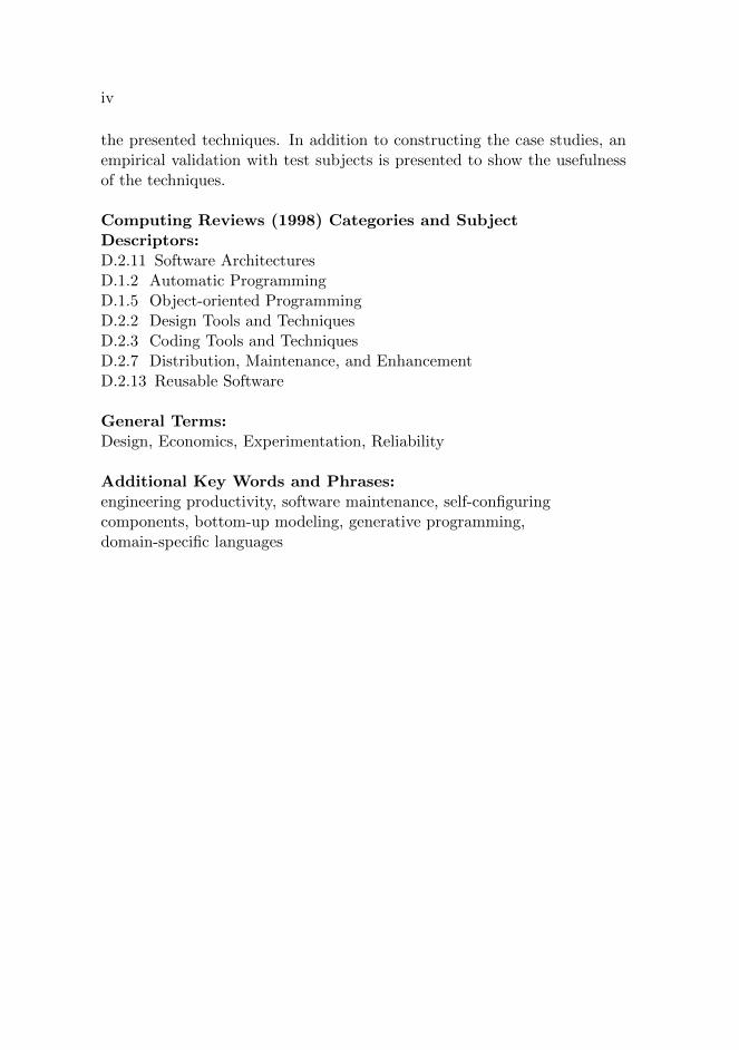
Computing Reviews (1998) Categories and SubjectDescriptors:D.2.11 Software ArchitecturesD.1.2 Automatic ProgrammingD.1.5 Object-oriented ProgrammingD.2.2 Design Tools and TechniquesD.2.3 Coding Tools and TechniquesD.2.7 Distribution, Maintenance, and EnhancementD.2.13 Reusable Software
General Terms:Design, Economics, Experimentation, Reliability
Additional Key Words and Phrases:engineering productivity, software maintenance, self-configuringcomponents, bottom-up modeling, generative programming,domain-specific languages

Acknowledgements
This work would not have been possible without the support from manypeople at the university, industry and in private life. First I would liketo thank Department of Computer Science, University of Helsinki for pro-viding the environment for completing this thesis and Graduate School onSoftware Systems and Engineering for providing financial support for at-tending to a number of scientific workshops and conferences. On personallevel, I would like to thank late professor Inkeri Verkamo for accepting meas a doctoral student regardless the unrealistic study plans. Dr. Juha Tainahelped a lot when translating my fuzzy ideas into formal, scientific text.Professor Jukka Paakki aided this text to gain its final form. I would alsolike to express my gratitude to Ph.Lic Juha Vihavainen for teaching me theinternals of compilers and MA Marina Kurten for helping with the Englishlanguage, often within tight deadlines.
Much of this work was done in context of industrial collaboration. Forthis reason, I would like to thank the companies involved, Digital Chocolateand Comptel Oyj. You have helped me to gain confidence that the things Iam working on have significance also outside the academia. I would also liketo thank people at National Institute for Health and Welfare for providingroom for finishing this thesis. Additionally, I would like to thank Applefor making easy-to-use backup systems installed on their computers. Onlythree Apple-branded computers were destructed during preparation of thisthesis.
Finally, I would like to thank my three girls, Eeva, Armi and Asta forgiving me alternative ways of spending my time.
Helsinki, November 11th 2013Pietu Pohjalainen
v

vi

Contents
1 Introduction 11.1 Summaries of original publications . . . . . . . . . . . . . . 3
1.1.1 Paper (I) . . . . . . . . . . . . . . . . . . . . . . . . 31.1.2 Paper (II) . . . . . . . . . . . . . . . . . . . . . . . . 31.1.3 Paper (III) . . . . . . . . . . . . . . . . . . . . . . . 31.1.4 Paper (IV) . . . . . . . . . . . . . . . . . . . . . . . 41.1.5 Paper (V) . . . . . . . . . . . . . . . . . . . . . . . . 41.1.6 Paper (VI) . . . . . . . . . . . . . . . . . . . . . . . 5
1.2 Thesis contributions . . . . . . . . . . . . . . . . . . . . . . 51.3 Thesis organization . . . . . . . . . . . . . . . . . . . . . . . 7
2 Preliminaries 92.1 Software engineering . . . . . . . . . . . . . . . . . . . . . . 92.2 Agile software engineering . . . . . . . . . . . . . . . . . . . 122.3 Non-functional requirements . . . . . . . . . . . . . . . . . . 142.4 Productivity in software engineering . . . . . . . . . . . . . 192.5 Economic model for investing in software development process 252.6 Recovering from the paradox . . . . . . . . . . . . . . . . . 31
3 Software architectures, models and product lines 333.1 Software architectures . . . . . . . . . . . . . . . . . . . . . 343.2 Model-driven software engineering . . . . . . . . . . . . . . 353.3 Modeling in agile software process . . . . . . . . . . . . . . 413.4 Software product lines . . . . . . . . . . . . . . . . . . . . . 423.5 Self-organizing and self-configuring software architectures . 49
4 Bottom-up modeling 534.1 Problems of top-down model engineering . . . . . . . . . . . 534.2 Bottom-up model-driven engineering . . . . . . . . . . . . . 544.3 An example . . . . . . . . . . . . . . . . . . . . . . . . . . . 564.4 When to use bottom-up modeling . . . . . . . . . . . . . . . 63
vii

viii Contents
4.5 Related work . . . . . . . . . . . . . . . . . . . . . . . . . . 64
5 Programs as models 675.1 Metaprogramming and generative programming . . . . . . . 675.2 Program annotations . . . . . . . . . . . . . . . . . . . . . . 705.3 Program fragments as the source models . . . . . . . . . . . 725.4 Related work . . . . . . . . . . . . . . . . . . . . . . . . . . 78
6 Conclusions 876.1 Contributions of the thesis . . . . . . . . . . . . . . . . . . . 876.2 Limitations of the thesis . . . . . . . . . . . . . . . . . . . . 896.3 Future directions of research . . . . . . . . . . . . . . . . . . 89
References 93
Reprints of the original articles 115

Contents ix
Original publications
This thesis consists of the following peer-reviewed publications and an intro-duction reviewing the area of study. In the thesis, the included publicationsare referred to by their Roman numerals.
I P. Pohjalainen: Restructuring optimizations for object-oriented mobileapplications. Proceedings of Workshop on New Horizons in CompilerAnalysis and Optimizations, Bangalore, India (2004).
II P. Pohjalainen: Object-Oriented Language Processing, Proceedings of7th Joint Modular Languages Conference, Oxford, UK (2006).
III P. Pohjalainen: Bottom-up modeling for a software product line: Anexperience report on agile modeling of governmental mobile networks.Proceedings of 15th Software Product Lines Conference, Munich, Ger-many (2011).
IV P. Pohjalainen: Self-configuring user interface components. Proceed-ings of 1st workshop on Semantic Models for Adaptive Interactive Sys-tems, Hong Kong, China (2010).
V P. Pohjalainen, J. Taina: Self-configuring object-to-relational mappingqueries, Proceedings of 6th International Symposium of Principles andPractice of Programming in Java, Modena, Italy (2008).
VI P. Pohjalainen: Transparent persistency seems problematic for soft-ware maintenance - A randomized, controlled experiment. Proceedingsof 8th International Conference on Evaluation of Novel Approaches toSoftware Engineering, Angers, France (2013).
In paper (V), J. Taina supported in formalization of the query inferencesystem’s description. The actual implementation was done by the author.

x Contents

Chapter 1
Introduction
Improving productivity is an everlasting quest in software engineering. Be-ing able to produce better software faster means opportunities to gain moreprofits for businesses, and to be able to serve customers better even whenno commercial interest is in place, such as in governmental organizations.In the past, this target has been approached in many ways, such as viadevelopment of different software process models, improving managerialproductivity, or by developments of e.g. better programming languagesand development environments, targeting programmer productivity.
Developments in programming languages have not improved productiv-ity much. The current mainstream of programming languages, such as Java[GJSB05] and C# [Mic07], have not been able to improve productivity inorder of magnitudes over older languages [BH12, McC04, p. 62]. Accordingto research, the way of using programming tools contributes more to pro-ductivity than the tool itself. Actually, it seems that software architectureis the driving force to alter productivity: well-suiting architecture is a boonfor productivity while an ill-suited architecture results in a major declinein productivity due to the required rework effort [TLB+09]. Empirically,one study found the average team size to be the most important factorwhen determining variance in productivity and the architecture used to bethe second in importance - while the programming language explains onlyone third of the variance compared to the architecture used [TMY+09]. Asanother example, the architecture of a given system, programmed in Java,can be monolithic or composed from modular pieces using a service-orientedarchitecture. In large systems, the service-oriented architecture can be agreat boost for productivity [Jon08, p. 220]. These reasons give us thefoundation to study software architectures in relation to software engineer-ing productivity. Overall, there are two main reasons to study better waysof organizing software architecture:
1

2 1 Introduction
1. Improved productivity enables cost savings and advantage in time-to-market.
2. Due to the specific nature of each software case, there is always roomfor improvement.
Reason number #1 deals with the competitive nature of the softwaremarket: unfit companies will be driven out of the market. Reason #2gives the inductive clause for development: since there is always room fordevelopment, not seizing these opportunities makes the company risk losingits fitness. For these reasons, we need to broadly chase all techniques thattake us further.
This thesis aims to improve engineering productivity by focusing onprogrammer productivity. The overall theme is characterized by the self-organization of software architecture on various levels. We describe variousmodel-based approaches that we have employed in real industrial projectswith real world constrains being applied. In many cases, we use advancedprogramming techniques, such as generative programming to achieve ourtarget. We explore the traditional model-based engineering and combinethose with program analysis techniques, producing a novel combination.In this thesis, we show that using the program under development as thesource model can benefit the programmer in ways of improved type safety,reduced effects of internal dependencies, and improved module compos-ability. These self-configuring components become architectural elementsof the software. In this thesis, these properties are examples of approachesfor making it easier to ship correctly working software in a shorter timeperiod.
We propose a new way to combine model-driven development and gen-erative programming. To increase industrial relevance, our solution takesthe limitations of agile development models into account. Our treatmentstems both from industrial experience and academic discussion of softwaredevelopment techniques. Although our goal is not to improve softwareengineering at the level of engineering processes or engineering team com-position, all our proposed engineering techniques can be and have beenimplemented in current agile industrial environments.
The techniques are presented in a form that describes specific problemsin specific programming environments. Our solutions of using specific toolsand techniques in specific contexts can be seen as examples or larger appli-cability in other contexts and using other tools. This is a way to demon-strate the wide applicability of our proposition of building long-lasting soft-ware systems via introduction of self-organizing software components.

1.1 Summaries of original publications 3
1.1 Summaries of original publications
In this section, we describe the included publications and show how theyare related to the subject of the thesis.
1.1.1 Paper (I)
In paper (I) we describe a technique for building a software product lineof mobile games for resource-constrained cell phones. In this context, theusual programming techniques, such as interfaces and abstract classes forbuilding modular software architecture are problematic due to the extraoverhead introduced by these classes. For this reason, many organizationsin the industry have abandoned object-oriented programming practices. Inthis paper, we present an algorithm for reducing the architectural overheadof interface classes and abstract classes by removing those architecturalclasses that are used due to software product line derivation. This way,the company does not need to compromise between maintainability of itsproduct line and single product resource consumption.
1.1.2 Paper (II)
Paper (II) discusses how a language processor can be implemented incre-mentally using a generative approach. The main contribution is an object-oriented construction, which allows parsing of object-oriented context-freegrammars within object constructors, despite the fact that in most object-oriented languages the object constructor is not polymorphic. We presentan incrementally extensible parser generator, which employs a variant of theVisitor pattern to improve the error messages produced by a strongly typedimplementation language in case of incompatible changes to the processedgrammar.
The paper can be seen as a traditional example of model-based gen-erative programming. A parser generator, which uses a grammar as itsinput, generates a part of the program. For language processing, actionsfor grammar productions can be hooked to the generator. This structureavoids the inherent problems of generative programming, where it is diffi-cult to interweave generated and handcrafted software parts.
1.1.3 Paper (III)
In paper (III), we document a case of building support for validating soft-ware product line instances. We approach the problem by re-using a well-known computational abstraction, regular expressions, to build a model

4 1 Introduction
in a known analysis technique of feature-oriented domain analysis. Wedocument application of a textual language as the source model and itsimplications in the context of an industrial software product line in thetelecommunication provisioning domain.
Here we present a theoretical bridge from regular expressions to featuremodeling. As a practical report, we also survey the model evolution thatwas experienced during development of a case study software product line.
1.1.4 Paper (IV)
In paper (IV) we explore the idea of using executable code as the modelin a model-based software engineering technique. In an industrial project,we had identified a problem of copy-paste coding in connection with Java’sstandard component-based user interface building technology. In the paper,we present a tool for reducing internal dependencies in architectures usingthe standard Java web development stack.
The resulting self-configuring component allows developers to build webapplications with fewer dependencies and improved support of producingmore precise messages to be shown to the user. This technique is use-ful when considering the maintenance tasks of the software, as possiblechanges to the user interface layer are automatically reflected in its depen-dent behavior. The automatic reconfigurations are also useful in the caseof product lines, where behavior changes based on the chosen configurationvariant.
1.1.5 Paper (V)
Paper (V) presents another example case of using software code as themodel for model-based software development. When using an object-to-relational mapping software component, a common problem is the depen-dency between a data-processing algorithm and its corresponding databasequery code. In this paper, we present a self-organizing database querycomponent that analyzes properties of the algorithm and constructs thecorresponding database query. This way, should the algorithm change, thefetching code is automatically updated as well.
Another benefit of this approach is that the need for re-defining thedatabase queries is reduced, since the automated query constructor com-ponent can analyze and create corresponding queries for multiple processingsites.

1.2 Thesis contributions 5
1.1.6 Paper (VI)
In paper (VI) we document the results of a randomized, controlled ex-periment of performing maintenance tasks using the technique presented inpaper (V). We assigned base software with a list of seven development tasksto randomly divided groups of students. The first group’s base software wasimplemented by using the traditional object-to-relational mapping imple-mentation. The second group’s software used the technique presented inpaper (V).
We used the number of correctly implemented maintenance tasks asthe measure of success. The result of the experiment shows that usingthe self-organizing database queries resulted in a statistically significantdifference between the groups with respect to code quality, as the membersof the second group produced 22 correct submissions while the control groupmembers were able to return only 5 correct submissions. Since the timeconsumed during the experiment did not vary between the two groups, it isevident that being able to produce four times as many correct submissionsin the same amount of time is a great boon for productivity.
1.2 Thesis contributions
The papers introduced in the previous section are manifestations of our ap-proach of building long-lasting software in practical settings. We have for-mulated our proposition to fit constraints mandated by e.g. agile softwareprocesses, since all the tools and techniques for productivity improvementcan be and have been implemented in a sprintable form.
Model-driven engineering is a recent movement with a promise for im-proved productivity. Productivity gains in limited domains, such as com-piler construction make the idea of raising the level of abstraction appealing.However, combining agile process with engineering approaches that includeany significant investment, or up-front planning, before the engineering dis-cipline can be employed can turn out to be problematic. Examples of thishave been discovered when combining agile processes with product-line en-gineering [McG08] and requirements engineering [PEM03], and when ap-plying architectural thinking with agile projects [ABK10, Mad10].
To fix these problems, we propose a flavor of model-driven engineeringthat takes into account the restrictions imposed by agile software devel-opment process models. This approach of bottom-up agile model-drivendevelopment recognizes smaller sub-domains within the software that areamenable for lightweight modeling. These small models can be used intraditional source-to-target generative programming or in some cases the

6 1 Introduction
source code itself can be treated as the source model, thus reducing redun-dancy. The bottom-up modeling approach entails lighter initial investmentthan domain-specific modeling, and thus allows fast experimentation cycleswithin the limits of tightly time-boxed agile iterations.
We pay special attention to self-configuring software components. Aself-configuring software component contains instructions for placing thecomponent in question into different contexts. The component knows howto adapt its parameters, up to a certain degree, when the context it isresiding in changes. The central idea is to reduce the harmful effects ofinternal dependencies, making it easier to maintain and further develop thesoftware. When the architecture of a software utilizes such self-configuringcomponents, the architecture can be said to be self-organizing.
Large software systems are full of interdependencies between modulesand other elements. For example, when using arrays as storage for holdingobjects, the size of the array must be large enough. This is a dependencybetween the size of the array and the number of elements placed in thearray. A self-configuring array analyzes its usage sites and automaticallydetermines the required size. This way, if the usage pattern changes dueto software evolution or for other reasons, the size of the created array isautomatically updated to reflect the changed reality. This kind of configu-ration cannot always be done automatically - the problem is unsolvable inthe general case. However, in many cases it is possible to automate the up-dating of dependencies, by using well-known software analysis techniquessuch as control flow graphs, variable def-use chains, class hierarchies, andother data structures that the compiler of a programming language alreadyuses during its compilation task. Currently the results of these analyses aretypically contained only within the compiler internals and are not availablefor application developers.
A self-configuring software component modularizes these kinds of anal-ysis tools and makes it possible to employ existing information to betterbenefit in improving software maintainability, improve software architec-ture’s support for implementing features and optimize established softwareproduct lines.
Our proposed techniques have long been used within homoiconic pro-gramming environments. Generative programming is a common practice inmany software products using functional languages as their implementationtool. Our results propose that many of these techniques are applicable ina non-homoiconic environment as well.
Our concrete contributions include a number of tools for generatingand optimizing architectural and code-level decisions in various domains,
1.3 Thesis organization 7
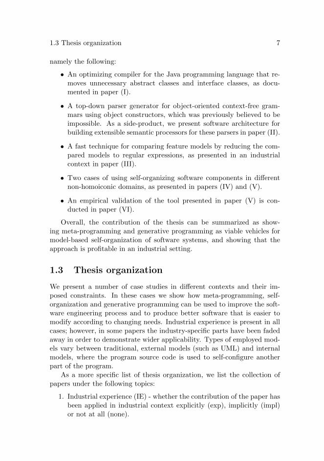
namely the following:
• An optimizing compiler for the Java programming language that re-moves unnecessary abstract classes and interface classes, as docu-mented in paper (I).
• A top-down parser generator for object-oriented context-free gram-mars using object constructors, which was previously believed to beimpossible. As a side-product, we present software architecture forbuilding extensible semantic processors for these parsers in paper (II).
• A fast technique for comparing feature models by reducing the com-pared models to regular expressions, as presented in an industrialcontext in paper (III).
• Two cases of using self-organizing software components in differentnon-homoiconic domains, as presented in papers (IV) and (V).
• An empirical validation of the tool presented in paper (V) is con-ducted in paper (VI).
Overall, the contribution of the thesis can be summarized as show-ing meta-programming and generative programming as viable vehicles formodel-based self-organization of software systems, and showing that theapproach is profitable in an industrial setting.
1.3 Thesis organization
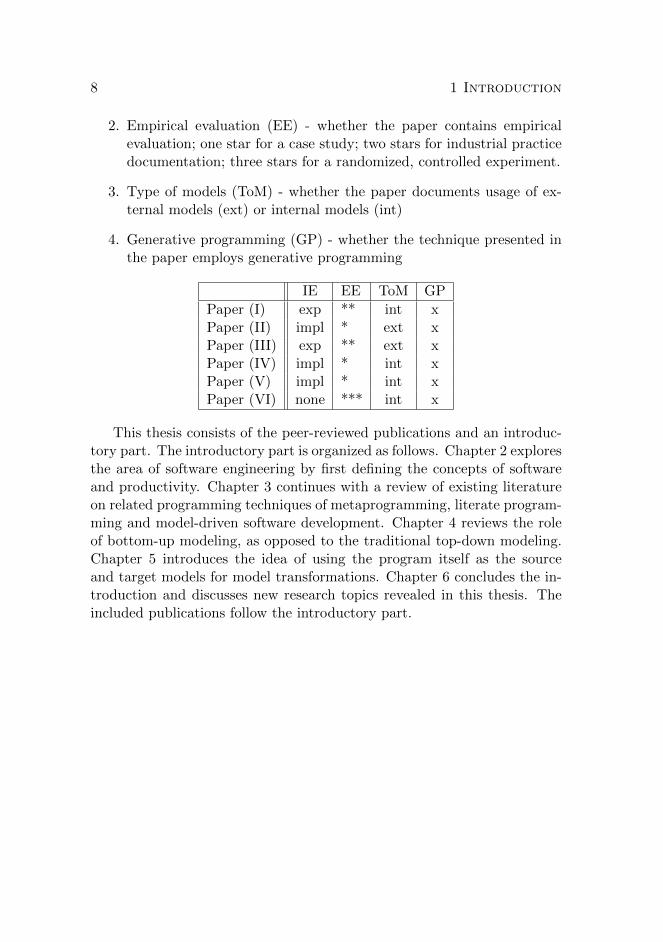
We present a number of case studies in different contexts and their im-posed constraints. In these cases we show how meta-programming, self-organization and generative programming can be used to improve the soft-ware engineering process and to produce better software that is easier tomodify according to changing needs. Industrial experience is present in allcases; however, in some papers the industry-specific parts have been fadedaway in order to demonstrate wider applicability. Types of employed mod-els vary between traditional, external models (such as UML) and internalmodels, where the program source code is used to self-configure anotherpart of the program.
As a more specific list of thesis organization, we list the collection ofpapers under the following topics:
1. Industrial experience (IE) - whether the contribution of the paper hasbeen applied in industrial context explicitly (exp), implicitly (impl)or not at all (none).
8 1 Introduction
2. Empirical evaluation (EE) - whether the paper contains empiricalevaluation; one star for a case study; two stars for industrial practicedocumentation; three stars for a randomized, controlled experiment.
3. Type of models (ToM) - whether the paper documents usage of ex-ternal models (ext) or internal models (int)
4. Generative programming (GP) - whether the technique presented inthe paper employs generative programming
IE EE ToM GP
Paper (I) exp ** int xPaper (II) impl * ext xPaper (III) exp ** ext xPaper (IV) impl * int xPaper (V) impl * int xPaper (VI) none *** int x
This thesis consists of the peer-reviewed publications and an introduc-tory part. The introductory part is organized as follows. Chapter 2 exploresthe area of software engineering by first defining the concepts of softwareand productivity. Chapter 3 continues with a review of existing literatureon related programming techniques of metaprogramming, literate program-ming and model-driven software development. Chapter 4 reviews the roleof bottom-up modeling, as opposed to the traditional top-down modeling.Chapter 5 introduces the idea of using the program itself as the sourceand target models for model transformations. Chapter 6 concludes the in-troduction and discusses new research topics revealed in this thesis. Theincluded publications follow the introductory part.

Chapter 2
Preliminaries
This chapter contains the required understanding of the background ofthis thesis. The preliminaries concentrate on various aspects of softwareengineering: agile engineering processes, non-functional requirements, pro-ductivity and the paradox of process improvement in an agile process. Therest of the thesis operates in the light cast in this chapter: we concentrateon the problems identified in this chapter.
The chosen viewpoints do not try to cover the full range of activitiesbeing done in software projects. Instead, these viewpoints are chosen fordiscussion because they tend to be sources of hard-to-fix problems for manysoftware projects.
Section 2.1 discusses the general state of software engineering. Sec-tion 2.2 extends the discussion to currently popular agile software engi-neering and presents the Scrum process model. Section 2.3 introducesnon-functional requirements with a special focus on maintainability andmodularity, as these -alities are in the core of building long-lasting soft-ware products productively. Section 2.4 changes the focus to productivityin software engineering, which is the key for companies and other softwareorganizations to be able to compete in the market place. In section 2.5,we develop a model for investing in software process improvement and in-troduce the paradox of process improvement in agile processes. Finally,section 2.6 explores the ways of resolving the paradox.
2.1 Software engineering
ISO/IEC/IEEE Standard 24765 defines software engineering as ”the ap-plication of a systematic, disciplined, quantifiable approach to the develop-ment, operation, and maintenance of software; that is, the application of
9

10 2 Preliminaries
engineering to software” [ISO10].
Software engineering as a discipline was born in the late 1960’s as aresponse to the software crisis, a term used to describe the phenomenonof software developers and software tools failing to keep up with the rateof hardware development [Nat68]. Advances in hardware allowed morecomplex software to be developed, but the means for handling the increasedcomplexity was lagging behind.
Since then, software engineers have explored ways to build larger andmore complex systems correctly and in predictable schedules. Generally,the final solution is yet to emerge.
However, in recent years, the area of software engineering has beenmaturing at a fast rate. In 1994, researchers of the Standish Group reportedthat only 16% of software projects were completed in time and in budget[Cha94]. In 2003, this number had doubled to 34%, as reported in a follow-up text [Cha03]. By 2009, the success rate had stayed in about the same,reporting 32% success in delivering projects on time, within budget, andwith required features and functions [Cha09]. Especially larger projectstend to be failure prone: according to productivity research, projects withover 10,000 function points1 have an alarming cancellation rate of almost50% with the remainder being delivered late and over budget [Jon08, p.216].
There has been an impressive improvement in success rates since theearly 1990’s. Still, much room exists for doing better. During recent years,one project out of three can be seen to be successful in these terms. Evenfor a success rate of 80% there is the other side of the coin: one projectout of five still exceeds its time or budget constraints. Although the Chaosreports have received negative feedback on their methodology and datavalidity [LEV10], the longitudinal data series is often cited as the definitivesource of high-level project success in software engineering.
Yet another viewpoint to this subject is that succeeding to meet timeand budget constraints is mainly the interest of the project manager ofa given project [AR06]. For other stakeholders, the primary interest canbe something else. For example, the client of the project is often happyto exceed the initial budget, when new opportunities for building betterfunctionality are discovered during the project [SAR12]. For this reason,whether a project meets its time and budget constraints cannot be con-sidered as the definitive success measure - but instead, the notion of suc-cess seems to be relative to the context and perception of the stakeholders[MM10].
1We will discuss the concept of function points in section 2.4

2.1 Software engineering 11
If we choose to dismiss the properties of project meeting its budgetand completing the features on time as a definitive source of project suc-cess, the next question is what is the alternative definition. One answer isthat we argue that small overcomes in budget and schedule do not mat-ter; and being slightly short of the functionality can be corrected at themaintenance phase. Another view is to regard software as a way of opera-tion; the software evolves along its surroundings. Then, the question is notabout meeting the budget and schedule, but about being able to respondto change requests in a timely manner.
Software process models
Great deal of attention in software engineering has been given to find outthe suitable process models for software construction. It was already quiteearly understood that software with any non-trivial complexity needs tobe developed iteratively [Roy70] instead of the one-way process from re-quirements to coding and operational use, which some people call ”thewaterfall”.
A classical way to characterize of different types of software systems isto divide them into three categories as follows [Leh80]:
• S-type programs, which are those that can be specified formally.
• P-type programs, which cannot be specified, but an iterative processis required for producing them.
• E-type programs, which interact with the real world, thereby chang-ing it. A feedback is needed to evolve the program according to newneeds.
The big majority of commercial software lies in the E-type category.New software enables new ways for organizations to work, which is reflectedin organizational structures. Changes in the organizational structures theninitiate changes to the software as well.
Scientific literature contains a number of different process models thattry to embed the requirements of the E-type category. Well-known ex-amples include the spiral model [Boe88] and the Rational Unified Process(RUP) model [Kru03]. Since nowadays the main use of these models ismainly limited to frightening sophomore-year students, we do not covertheir specifics further. The interested reader can see the standard softwareengineering textbooks, such as [Som10, Pre10, Sch05] for a more thoroughdiscussion of these software process models.

12 2 Preliminaries
During the last two decades, the mainstream of software developmenthas turned into using different kinds of agile processes.
2.2 Agile software engineering
The currently popular agile process methods help projects to avoid big mis-takes of producing the wrong product to the wrong customer at the wrongtime. Improved communication with the customer, learning effect withinagile iterations and time-boxed development all contribute as process-levelreinforcements to project work.
The agile manifesto [HF01] gives four high-level guidelines for agile soft-ware projects:
• Individuals and interactions over processes and tools.
• Working software over comprehensive documentation.
• Customer collaboration over contract negotiation.
• Responding to change over following a plan.
These preferences are not to be regarded as mutually exclusive choices,but rather as experience-shown preferences on which to give priority incase of conflict. For example, a study on developer perspectives in softwaredevelopment reported a case where the project that developers felt to bethe most successful was also reported to be most lacking in tool support[Lin99].
For a general overview of the various agile methodologies, the interestedreader can read a comparative survey by Abrahamsson et al. [AWSR03].Currently, the majority of agile development teams use the Scrum develop-ment model, with over 75% deployment rate reported in year 2011 [SS12].
Scrum
Scrum [Sch95] is an agile process model intended to fix deficiencies in itspredecessors, the waterfall, spiral and previous iterative models. The mainidea is to loosen the requirements for the process during iterative sprints:only preplanning and system architecture phases and the closure phasehave a defined process. Inside the sprints - when the heat is on - there isminimal bureaucratic overhead. The name Scrum was first used to describethe way how Rugby players change their playing style according to eventsin the play field: during the game, a player cannot ask directions from

2.2 Agile software engineering 13
the coach, but he needs to take his own initiative. The same is thoughtto apply to software development as well: for maintaining flexibility, notevery change needs to be accepted by the project management. Figure 2.1gives an overview of the activities in the Scrum methodology.
Figure 2.1: Scrum methodology [Sch95]
The interplay between well-defined, rigorous process and creativity-enabling freedom is balanced by having the planning and closure phases usedefined processes. Here all processes, inputs and outputs are well definedand knowledge of how to execute is explicit. The flow is linear, with someiteration in the planning phase. The sprint phase is a different beast: it isan empirical process. Many activities in the sprint phase are unidentifiedor uncontrolled. Management-wise, it is treated as a black box, with onlylimited controlling interfaces, such as risk management given to preventchaos, but otherwise targeting to maximizing flexibility [Sch95].
A sprint is a time-boxed set of development activities. The usual timelimit ranges from one to four weeks; based on product complexity, risk as-sessment and degree of required oversight. Within the sprint, one or moreteams concurrently execute phases of development, wrap-up, reviews andadjustment. Development consists of the actual doing: defining what isneeded to be done in order to fulfill the development items in the backlog:domain analysis, design, development, implementation, testing and docu-mentation. Wrap-up is the phase of building deliverable software. Reviewactivities are the parts that require team communication to present workand review progress. Adjusting activities are those adjustments that are

14 2 Preliminaries
discovered after reviews [Sch95].
It is important to note that these activities run sporadically within theiteration. During planning and system architecting, the general strategyfor the next iteration is defined. However, if the situation changes duringthe sprint, the plans need to be adjusted ’on-the-fly’.
In the beginning of this section we reviewed how only a small fraction ofsoftware projects are able to deliver the required functionality within sched-ule and budget. Achieving this target is easy in Scrum. This is because allthree components of this ’iron triangle’ of required functionality, scheduleand budget are defined in the project with the permission to redefine whenthe original estimates turn out to be overly optimistic.
Overall, the Scrum method promises throughout responsiveness to en-vironment with a permission to use unlimited creativity within sprints - asopposed to cookbook approaches in the predecessor process models. Theproblem of knowledge transfer is thought to be handled through teamworkduring the project.
From the productivity viewpoint, the Scrum model has been success-ful, especially in small projects. According to productivity research, Scrumand other agile software engineering methods are providing the best pro-ductivity rates amongst the compared technologies in applications of size1,000 function points. For example, Scrum combined with object-orientedprogramming is said to achieve three times higher productivity than thetraditional waterfall: Scrum+OO averages to 24 function points per staffmonth while the waterfall method averages to only 8 function points [Jon08,p. 220].
2.3 Non-functional requirements
When deciding whether a software product meets its specification, softwareprofessionals tend to primarily think about the functional scope of the prod-uct [AR06]. However, the causes for software to not meet its specificationis seldom related to not being able to provide the required functionality;more often the root cause is related to poor quality [Jon95] or other non-functional requirement.
Non-functional requirements document non-behavioral aspects and con-straints of the software. In addition to performance requirements, non-functional requirements include a number of ”abilities”, e.g. reliability,usability, security, availability, portability, and maintainability [Gli07].
The non-functional requirements are notoriously difficult to express incontracted software development [CdPL02, PKdWvV12]. In the view of

2.3 Non-functional requirements 15
agile productivity, the first five abilities mentioned above can be regardedas normal requirements: regarding these, the software can be iterativelydeveloped until the customer is happy. The last one, maintainability, hasa different nature. It is the degree of maintainability that dictates howefficiently all other abilities and emerging new functional requirements canbe implemented. For this reason, we will study maintainability a bit more.
Maintainability
According to Lehman’s first law on software evolution, software is a livingentity [BL76]. It is not enough to get a software product deployed intoproduction once; instead the time of deployment is when a new softwareentity is born. The newborn baby starts to grow through maintenancetasks, which adjust the functionality of the software to fit the changingenvironment it lives in.
Maintenance tasks often consume the majority of resources spent duringthe lifetime of a software product. Software engineering knowledge citesthe amount of maintenance effort to range from 66% to 90% of the overallspending in software projects [Pig96, Sch05, SPL03].
The importance of maintainability is especially relevant when operatingin the agile mode. The repeated iterations with the proposition of embrac-ing change can cause unbearable pressure if the software has not been builtto be maintainable. Actually, some professional programmers advocatethat programming should always be done in the maintenance mode [HT99,p. 27].
Evolvability has been mentioned as being on the top-level importancein computing [Den03]. Some researchers even argue that software evolu-tion is the most important factor to influence productivity in any softwaredevelopment project [Nie02]. Especially in the area of agile software de-velopment, this statement is true due to short iterations and the need forability to change the direction of development after any given iteration.
Maintenance-related tasks have a high relative weight in effort distribu-tion charts. Thus, applying techniques to make maintenance-related taskseasier should be a key priority for software designers and in software ar-chitectures. For example, a central problem in software maintenance isin understanding all the internal dependencies in the system. Systematicrefactoring can be applied to reduce the effort of changing the same code inmany places [Fea04, p. 269-287]. However, this kind of advice is targetedto the maintenance programmer, who needs to understand all the depen-dencies in order to be able to refactor a better design. It would be betterto design the system in the first place in such a way that the dependencies

16 2 Preliminaries
do not hurt the maintenance programmer at all.
In general, maintenance refers to all the tasks that are required to keepan already shipped software product to fit in its changing environments. Ausual classification of maintenance splits these tasks to corrective mainte-nance, adaptive maintenance and perfective maintenance [Swa76, LS80, p.68].
Corrective maintenance consists of the tasks required to fixing the soft-ware bugs; all the work that could not be billed if the software was stillunder warranty. Adaptive maintenance refers to tasks where there is a needto change the software due to changes in data input or requested changesin output formats or interfaces. Perfective maintenance in turn consistsof enhancements for users, improvements in software documentation andimprovements in software performance [LS80, p. 68]. At later times, therehas been a tendency to further classify parts of this effort into preventivemaintenance, it being included as the fourth maintenance factor in theIEEE standard on software maintenance [ISO06]. Preventive maintenanceconsists of those tasks that are not performed due to bug fixing or user-requested enhancement, but to prevent failures in the future or to make theother types of maintenance tasks easier. In software context, many preven-tive maintenance tasks can be thought of being code refactorings withoutobservable changes in functionality [Opd92].
Of all of these categories, the non-corrective maintenance tasks are theones where most of the effort is being spent. Non-corrective maintenancehas consistently accounted for over half of the effort spent in maintenance[AN93, DA10, LS80, p. 68]. In summary, this is the category of softwarework where the biggest share of software teams are spending their largestamount of time. A direct economic implication is that any techniques thatcan be used to reduce the absolute amount of effort spent in this share dosignificantly reduce overall software costs.
For maintaining existing software, there are textbooks that recognizecommon cases of maintenance-related refactoring tasks. Current devel-opment environments offer a range of automated refactoring tasks. E.g.[Fea04] documents 24 techniques for breaking dependencies in legacy object-oriented code that does not (yet) follow the current best practices of build-ing unit tests, test-harnesses and design for testability.
Modularity
Building modular systems is a way to reduce the required effort in mainte-nance. Using correct tools to solve the right problems can yield big benefits.An early study reports that 89% among users of structured programming

2.3 Non-functional requirements 17
reported improved maintainability of their code over unstructured program-ming [LS80, p. 7].
Programming languages contain a number of modularity techniquesto improve productivity in software construction. For example, object-oriented programming and aspect-oriented programming are essentiallyways to use suitable abstractions for developing reusable building blocks.
Program development by composing the program from a number ofsmaller building blocks is thought to be an efficient way of software engi-neering. However, the real problem is how to find the correct componentsand how to glue them together. Object-oriented programming introducesthe notion of object as the basic building block. Aspect-oriented program-ming supports different aspects to be introduced to the program, allowingthe functionality of the program to be defined from different angles. In bothof these approaches, the joining of different modules is still done manually.
Designing modular architectures is the key when planning to supportmaintainability of software. There are a number of obstacles to hurdle whenapproaching a good decomposition of software to modules. However, thechosen decomposition greatly affects how well the software is modifiable, aswas shown in an early study of two software implementations with differentmodular decompositions [Par72]. Although a good modular decompositionhelps in further maintenance, it should be noted that in many cases the”perfect” decomposition does not exist, but instead any chosen decompo-sition is a compromise that favors one maintainability aspect over another.Any chosen way to modularize the software will serve some purposes onthe expense of some other. This is known as the tyranny of the dominantdecomposition [TOHS99].
The term modularity is unfortunately rather overloaded and requiresclarification, since its meaning varies from one environment to other. Forthis section, we will use a metaphor of Lego® bricks to discuss modularityin a broad sense. These widely known plastic bricks can be seen as ametaphor for modularity. Each one of the little plastic bricks defines acertain connectivity interface through its upper and lower interfaces. Whentwo bricks are connected through these interfaces, they form a new element,which can be regarded as a single, larger element with its own connectivityinterface. Generation after generation, children’s creativity is tickled withthese simple but infinitely modifiable toys – there are hundreds of millionsof ways to connect six 2x4 bricks [DE05].
One can reason about these two bricks and their corresponding compo-sition algebra: two 2x2 bricks can be connected in 18 different positions2.
272 different ways if the cheeks of the bricks are considered to be distinct

18 2 Preliminaries
One of these combinations is shown in Figure 2.3 as an attempt to startbuilding an infinite stream of steps.
Figure 2.2: Two 2x2 Lego® bricks connected
Adding a third 2x2 brick makes the compound model even more compli-cated: now there are 729 different ways the three pieces can be connected.When continuing with the attempt of building the stairway to heaven, apreviously unknown force, gravity, steps in. Each object in our physicaluniverse has mass, which causes all objects attract each other in force pro-portional to their mass. When the structure in Figure 2.3 is placed on aneven surface, its center of gravity is outside the bottom surface area of theblue brick. Thus this structure crashes when no additional force is used tokeep it in balance.
Figure 2.3: A three-step model with its internal balance out of bounds
Working in software development often reveals similar forces in the soft-ware. The software and its structure can work well in one configuration, butafter a number of changes following the current architecture, its internal”center of gravity” is exceeded and the system crashes. Due to the natureof maintenance programming, the maintainers are not always fully awareof the forces defining the internal ”center of gravity” of the maintainedsoftware.
Software is full of these kinds of hidden dependencies, where a seem-ingly innocent change can cause malfunction or crashing. Programmershave learned to defend themselves and their colleagues and customers fromexcessive rework by designing their software in a way that is resilient tofuture changes. One way is to document the anticipated ways of future

2.4 Productivity in software engineering 19
modifications.
A pattern of documenting the maintenance tasks [HH04] can be usedto expose the software’s internal dependencies and to guide maintenancepersonnel to the right direction when modifying the software’s structure.For our bricks metaphor, a maintenance pattern would be stated as instruc-tions to maintain the center of gravity in the overall structure, possibly byadding counter-weighting bricks to any structure-modifying addition.
It is easy to confuse intentional and accidental maintainability. Pro-gram designers and programmers often use constructs that are primarilyintended to act as a functional construct, while their purpose is just to buildsafeguard constructs to improve maintainability. We can call this kind ofdesign a case of accidental maintainability. We need to distinguish thoseconstructs from intentional cases of a priori, explicitly designed maintain-ability.
In the Lego brick example, a case of accidental maintainability for main-taining the brick-structure’s balance could be to place a certain number,say five, of counter-weight bricks on the first step. This way, the structure’scenter of gravity would stay within its constrained limits when new stepsare added, up to five steps. However, this approach is problematic in twoways: first, it wastes resources when less than five steps is needed. Second,when there is a need for the sixth step, the system crashes.
A system of intentional maintainability in this example would identifythe dependency between the number of steps and its implications to inter-nal balance. Intentional maintainability would then instruct the stairwaybuilder to add the required counterweight for any number of steps.
2.4 Productivity in software engineering
Productivity is a key issue in professional software development. In manysoftware businesses, being able to produce more functionality in a giventimeframe is advantageous: in a productive environment customers gainmore value from software projects, and project professionals have higherjob satisfaction. However, relatively little attention has been paid to actualproductivity improvements in agile projects. This is surprising, given thefundamental nature of productivity and productivity improvement in thehistory of industrialized world.
The definition of productivity involves the ratio of outputs to inputs,such as material, labour, and capital. Thus, productivity is defined asfollows [Boe87]:
productivity = outputs/inputs (2.1)
20 2 Preliminaries
An organization that can produce more products with less resources ismore productive. Being able to produce more outputs with the same inputmakes an organization more productive; and producing the same outputwith less input again means better productivity. However, in the context ofsoftware engineering, the definition of productivity is problematic, mainlydue to the definition of output part of the equation.
In many cases, the inputs can be estimated. This variable includesthe resources consumed in the project. While some disagreement on theattribution of indirectly involved resources such as departmental secretaryservices is unavoidable, usually companies and organizations can settle toa rough agreement on division of these costs. The inputs can be in variousforms, such as computing resources, network resources in addition to humanresources. However, a conversion to present currency value can unify theconsumption to a single number [Boe87].
The output part is the problematic to define [Boe87]. One suggestion isto define the outputs as the delivered functionality at certain quality level[Nie02]. However, this attempt does not solve the measurement problem:what is the unit of functionality or quality? In order to measure, there needsto be units of measurement. In the following, we review few traditionallyused measures, the lines of code and function points.
Lines of code
Lines of code and its variants, such as source lines of code and deliveredlines of code are the easiest variables to measure. Even crude tools, suchas the wc utility can be used to give a crude estimate and more accuratetools can easily be obtained from open source software repositories. Forthis reason, lines of code is industrially used measure for software size.
Also some scientific studies, such as [AK04, MAP+08] use lines of codeas the output measure. However, lines of code is a notoriously bad mea-sure for productivity [FP98, pp. 405-412]. Actually, quite the contrary:researchers associate less code lines to be the key to productivity [TB03].
Bill Gates is quoted of saying, ”Measuring programming progress bylines of code is like measuring aircraft building progress by weight”, whichis a nice analogy in two ways: first, it emphasizes that the goal in buildinga good airplane is not to make it heavier, but to make it lighter. Thesecond interpretation of the analogy is that big aircraft are distinguishablydifferent from small aircraft; similarly, a software whose size is measured intens of millions of lines of code is different from a software whose size is intens of thousands.
In the micro scale, the measurement in lines of codes is irrelevant. As

2.4 Productivity in software engineering 21
an example, consider the code listing in Figure 2.4. This code loops fora specified number of times, and sleeps for one second. An equivalentcode could be written by unrolling the loop. This means to remove thefor-loop and to copy the loop body for the five times and substitutingthe loop variables with corresponding values and performing the stringconcatenations at coding time. In this case, the equivalent code would beas shown in Figure 2.5.
for(int i=1; i<=5; i++) {
Thread.sleep(1000);
System.out.println(i+" second" +(i==1?"":"s")+ " passed.");
}
Figure 2.4: Code for watching the time go by
Thread.sleep(1000);
System.out.println("1 second passed.");
Thread.sleep(1000);
System.out.println("2 seconds passed.");
Thread.sleep(1000);
System.out.println("3 seconds passed.");
Thread.sleep(1000);
System.out.println("4 seconds passed.");
Thread.sleep(1000);
System.out.println("5 seconds passed.");
Figure 2.5: Unrolled code for watching the time go by
The unrolled version is probably more efficient, since it does not spendtime in calculating the loop conditions and constructing the current messageobject. However, very few professionals would prefer the unrolled versionover the looping version in source code form: it violates the do not repeatyourself (DRY) principle, which has been found out to be a good guidelinein constructing easily modifiable software [HT99, p. 27]. If we were to useline count as the numerator of the productivity equation (2.1), the unrolledversion would yield a higher productivity index, since the first version linecount is 4, whereas the unrolled version contains 10 lines to produce thesame output.
The DRY-principle is not limited to this kind of mechanical loop un-rolling, but applies also to questions of code style. To illustrate this idea, let

22 2 Preliminaries
us consider a simple command interpreter, implemented in the C languageas shown in Figure 2.6.
struct command
{
char *name;
void (*function) (void);
};
struct command commands[] =
{
{ "quit", quit_command },
{ "help", help_command },
...
};
Figure 2.6: Interpreter implementation as an array of structs [SW11, p. 19]
The code in Figure 2.6 defines an interface for defining commands. Eachcommand has a name and a pointer to a function implementing the com-mand. By convention, each function is named after the command it imple-ments.
This is a violation against the DRY-principle: the prefix in the functionname in the command table repeats the name of the command [SW11, p.19]. Thus, it is considered to be cleaner to factorize the command namesas a common element, e.g. by using preprocessor directives. An equivalentcode, without repetition could be formed as shown in Figure 2.7.
#define COMMAND(NAME) { #NAME, NAME ## _command }
struct command commands[] =
{
COMMAND (quit),
COMMAND (help),
...
};
Figure 2.7: Interpreter implementation by preprocessor concatenation[SW11, p. 19]
In Figure 2.7 the code uses the C preprocessor token concatenationoperator [Ker88, p. 90] to define a macro for each of the commands. In

2.4 Productivity in software engineering 23
this example, after the preprocessing phase the source code is exactly thesame as the code in Figure 2.6. The latter version can be argued to becleaner and easier to understand.
Using line count as the productivity measure does not detect any differ-ence between these two alternatives. However, when programs get biggerand more complex, the quality of the code starts to make a difference. Acodebase with needless repetition and many dependencies can easily deteri-orate into an unmaintainable state. Using the line count as a productivitymetric can add great momentum to the demise of the project.
Function points
The problem with the number of lines as a measure of software developmentis well known. In order to better understand development progress andto be able to compare similar software written in different languages, theconcept of function points has been developed [Alb79].
The idea with function points is to estimate the functionality of thesoftware at higher level of abstraction than just the actual lines of code.When estimating the number of function points in a software, its function-ality is dissected into small pieces that can be explained by the functionpoint analysis method.
Function point analysis is based on estimating data functionality andtransaction functionality. There are two types of data functionality: in-ternal logical files (ILF) and external interface files (EIF). For transactionfunctionality, the estimation is based on three types of transactions: exter-nal inputs (EI), external outputs (EO) and external inquiries (EQ). Eachoccurrence is judged to be simple, average or complex. Figure 2.8 gives anoverview of how application logic is estimated
For a given feature or component of a software system, the complexity-adjusted data and transaction functionalities are charted through functionpoint analysis tables, which give out unadjusted function point values. Fi-nally, this value is translated to the final function point value by applyingthe value adjustment factor, which reflects the non-functional requirementsof the system. To get an estimate of the whole system, this process is re-peated for all of its components.
Function point analysis is a lengthy process. A necessary pre-requirementis the functionality of the software to be well understood, since otherwiseit would be impossible to enumerate all the components of the system.For this reason, function points are not widely used in software develop-ment methodologies that de-emphasize overly detailed upfront planning.Another problem with function points is that they suit only certain types

24 2 Preliminaries
Figure 2.8: Elements of function point analysis
of application software. When applied in an inappropriate domain, suchas operating systems, the result can be that functionally similarly lookingoperating systems targeted to the mobile phone and the desktop receiveequal amount of function points, as happened when estimating the AppleMac OS X full version and its mobile variant iOS [Jon08, p. 274].
Despite of not being a perfect measure, function points do provide abetter view on sizing of software than lines of code, especially in sizingform-based information systems. Function points can be applied acrossdifferent programming languages and development methodologies to gainunderstanding of whether investments to improved ways of working aredelivering the promised benefits. For different programming languages,there are statistics-based equations for finding crude correspondences be-tween lines of code and function points. These equations can be used toanticipate the software’s implemented size when its functionality is knownin function points; or to estimate the software’s functionality in functionpoints when its size in lines of code is known. However, it should be notedthat these estimates are rather crude, as the software’s architecture andthe applied conventions in an individual project can have big effect to theactual results.

2.5 Economic model for investing in software development process 25
2.5 Economic model for investing in software de-velopment process
When investing in process improvement in software development, the ob-vious question is how to estimate the return-on-investment. Return-on-investment (ROI) is calculated by dividing the difference of benefits andcosts of a change by the costs of the change [Phi94, pp. 12-13], as shownin formula (2.2).
ROI(%) =Gain− Cost
Cost∗ 100 (2.2)
In software development, the most important result is the working soft-ware system. As this result is abstract in nature, it is often hard to estimatecauses and effects in the work producing the software. For this reason, alsogiving exact figures for estimating whether process improvement is justi-fiable is problematic in many cases. However, the general principles ofeconomic thinking can be used to guide in decision making, although theexact numbers for a given decision might be impossible to calculate.
When a software development team is given a task to implement asoftware product, the total cost of the project can be calculated as statedin formula (2.3).
OC ∗OT (2.3)
In this formula, OC stands for operational cost and OT for operationaltime. In a single project scope, operational costs are usually mandatedby the organization. Operational time is the time that the project needsto produce the required functionality. The more efficient the developmentteam, the shorter time is spent in development. Equation (2.3) thus is de-pendent on total factor productivity [CROB05, p. 3], which is productivitymeasure that encompasses all the factors in consideration.
For example, if the average cost of one man-month in the project, in-cluding the salaries, office spaces, cost of computer leases and so on, is 10units, operating a software development team of ten people costs 100 unitsper month. If the software development project takes three months, thetotal cost of the project is 300 units.
Considering productivity improvement, the use of technologies for soft-ware development varies from organization to another. In traditional man-ufacturing context, the production frontier [CROB05, p. 3] refers to thecurve of how many output units can be produced per one input unit whenthe production is scaled and the organization is using the best technology

26 2 Preliminaries
for production. In production frontier, usually a larger scale yields less re-quired input per output. An organization that is at the production frontieris said to be technically efficient.
Software development projects are seldom technically efficient. CapersJones has presented an estimated an average of 35% efficiency in softwaredevelopment [Jon94, p. 228]. The requirements are typically defined dur-ing the project, which causes changes in the technologies for reaching theproduction frontier. Even if a project happened to be technically efficient,technical changes in development environment can cause the productionfrontier to move [CROB05, p. 4].
This is good news for productivity improvement: there is a lot of workto be done. However, application of technical changes and improvementproposals for moving towards the production frontier need to be justified.Seldom do these changes come for free: instead, all changes have an as-sociated cost, and they take time to be implemented. On abstract level,the economic decision criterion for performing an improvement, using anygiven technical change or by adjusting the development process can be ex-pressed as in equation (2.4), where the new term OT’ stands for the newoperational time after an investment to a changed way of working.
OC ∗OT > Cost + OC ∗OT ′ (2.4)
In other words, the initial investment to implement new practice oremploy new techniques within the project can be justified if the costs withnew operations amortized over total operational time are smaller than thealternative of running the operations without changes.
Let us have a hypothetical development practice that gives 25% im-provement on productivity with no other consequences to related variables.Implementing this practice has a fixed cost of 50 units and it is immedi-ately implementable whenever the project chooses to. If available at thebeginning of the project it should be employed, as the improvement on pro-ductivity shortens the required time to implement the project from threemonths to 2,4 months, thus promising an earlier delivery and overall sav-ings on expenses. However, if the given practice becomes available at thebeginning of the last month, it is no longer clear whether it is justifiableto employ the practice for this project. The improved productivity allowsthe work in the last month to be performed in 80% of the time. However,the saving of 20 units in operating cost does not warrant offsetting theinitial cost of 50 units for this practice - but instead causes the overall de-velopment bill to exceed the budget by 30 units3. However, the improved
3100+100+80+50 = 330

2.5 Economic model for investing in software development process 27
Figure 2.9: Expenditure graph
productivity allows to ship at a week earlier, so depending on the contextthe higher total cost might still be justified by faster time-to-market.
Figure 2.9 draws an expenditure graph for the three alternatives. Thebaseline spends all three months with linear spending curve. When theproductivity upgrade is obtained in the beginning of the project, the initialcost is higher, but the improved productivity gives faster completion timeand smaller expenses. The productivity upgrade, brought at near end ofthe project still gains faster shipping, but the overall cost is the highest.
In reality, this kind of reasoning for real software projects is very hard,maybe impossible. This reasoning does not take into account Parkinson’sobservation [Par57]. This observation refers to the phenomenon of work ex-panding to fill all the available time. Our example assumes a fixed amountof work, which seldom is the case. In practice, the 20% of the time savedin the last month would probably not be used to ship earlier, but insteadbe used in various, unaccountable ways, such as gold plating the software,which is a known anti-pattern of commercial software development [McC96,p. 65].
Another problem is that productivity rates vary between individualsand team mix-up in orders of magnitude [Gla02, pp. 14-15], and the hy-pothetical instant productivity boon option is just a project manager’sdaydream. Instead, various factors, such as the learning curve [Gla02, pp.23-24], suitability of improvement into context and scalability of the im-provement need to be taken into account. These are not easy to estimatebeforehand.
However, the basic principle behind equation (2.4) is often encountered
28 2 Preliminaries
in software development organizations: new practices and technologies arediscovered, and a return-on-investment justification needs to be found foremploying the practice in question. Unfortunately, most often the exacteffect of the practice is not well understood; but instead, practicing profes-sionals are faced with vague explanations of merits of the new technique.Even with a piloting implementation in the organization, it is very hardto measure the exact effect of the new technique, as distinguishing thenew technique’s effect from other productivity measures is mostly based onindividual feelings rather than objective measures.
Process improvement in agile processes
The example in previous section discussed an extremely simple processmodel with a fixed amount of work to be done. Real software projects,especially the ones employing agile principles, are by nature more chaotic:accepting the fact that requirements are not known beforehand and thefact that the direction of development might change at any iteration, agilesoftware teams agree with their customer on a time-boxed developmentmodel.
From the process development viewpoint, the principle of sudden changeis problematic, as intra-project improvement cannot be justified via amor-tizing the investment costs to future iterations. This is because the dealwith the customer does not last longer than to the end of the iteration: thenext iteration materializes only if the shipping product in the end of theprevious iteration pleases the customer well enough and assures him thatthe value brought by implementing the next iteration exceeds the cost. Forthis reason, all work in an agile project needs to be in sprintable form[Mad10].
This strict time-boxing of software development in agile process mod-els introduces an additional constraint to the economic decision criterionof equation (2.4). Given a two-week sprint cycle, as exercised by manycompanies following the Scrum model [Sch95], any process improvementinitiative needs to be fit in the same cycle. Traditional justification forreturn-on-investment calculations spans for the range of many months orup to a year [VS04].
At this point, we need to discuss about value of the work, i.e. whatis gained by assigning an engineering team to a given problem. Given abaseline productivity, the value of the work is
value = OT ∗ P (2.5)
In equation 2.5, P refers to the productivity of the team, which is 100%

2.5 Economic model for investing in software development process 29
for the baseline. Equation 2.4 discusses whether productivity improvementcan be justified by cost savings. Agile projects are more interested in deliv-ering value to the customer. Thus, the economic decision criterion in agileprocess models translates to the following format:
OC ∗OT ∗ P < Cost + OC ∗OT ∗ P ′ (2.6)
The difference between equations 2.4 and 2.6 is that in the former, aninvestment to software development process is justified by the shorteneddevelopment time indirectly brought by productivity improvement. In thelatter equation, the operating time is the same on both sides: regardless ofproductivity, the team commits to a single, time-boxed iteration at a time.Improved productivity brings more value to the customer: however, thereis a paradox in that tighter time-boxing reduces the room for productivityimprovement, since the cost of any improvement must be paid within thesame time-boxing unit where it is to be taken into use. Otherwise, theteam is not delivering full value to the customer.
It will be very hard for the suggested initiative to gain acceptance withinthe development team if it is not deliverable within agile iterations, ascommitting to the process improvement also endangers the continuity of thewhole project. This happens not only because the external environment issetting the team’s development tact to follow the time-boxed iterations, butalso due to the internal pressure within the team to follow agile principlesof meeting demands of the customer by the end of every iteration.
These reasons can be formulated as the paradox of agile process im-provement: In an agile project, the closer the customer is watching theproject, the harder it is to implement productivity improving practices.
On-site customer is a core extreme programming methodology princi-ple. However, on productivity improvements angle this principle is contra-dictory: any investment that is expected to pay off after more than oneiteration in improved productivity cannot be justified, because the agree-ment on the next iteration is based on the outcome of the current iteration.If the development team induces the customer to include additional processimprovement efforts to a single iteration, the team is steering away fromthe agile principles of delivering value at the end of each iteration.
The paradox of agile process improvement is also related to issues ofarchitectural problems in agile projects. As the agreed scope for a givenproject does not last over the end of the ongoing iteration, any effort spenton improving the internal working methods is perceived as lessening theavailable effort for value creating activities. Lack of time to consider designalternatives has been recognized to be a problem for many agile projects

30 2 Preliminaries
[Bab09].For this reason, the process improvement schemes available to a project
using an agile process are limited to well-matured techniques with proventool support. Examples of agile-associated techniques are e.g continuousintegration, unit testing and version controlling. Each of these process tech-niques are clearly initially implementable within a very short timeframe,thus not endangering the value delivery promise within the iteration. Still,e.g the documentation for Selenium, a well-known web software test au-tomation tool raises the question [HISMP+13]:
”Is automation always advantageous? When should one decideto automate test cases? It is not always advantageous to auto-mate test cases. There are times when manual testing may bemore appropriate.”
For Selenium, the authors find two example cases in which investmentfor building test automation is not beneficial: If it is known beforehandthat the application structure is going to change considerably, building testcases would be wasted effort. Another case is that sometimes there simplyis not enough wall-clock time or developer time to do this:
”[S]ometimes there simply is not enough time to build test au-tomation. For the short term, manual testing may be moreeffective. If an application has a very tight deadline, there iscurrently no test automation available, and it’s imperative thatthe testing get done within that time frame, then manual testingis the best solution.”
This viewpoint emphasizes the need to balance between short-term andlong-term goals. Due to the fact that in agile projects the next deadlineis always very soon, it is difficult to justify much investment in buildinge.g. test automation, as it does not bring direct value to the customerby the end of the on-going iteration. However, this kind of investment ismandatory when efficiency in development is a target goal.
In the running example at the beginning of this section, the hypotheticalproductivity implementation was assumed to be available immediately andat a fixed cost. In reality, this is a rare case to happen. Instead, newpractices take time for the development team to get accommodated to, andbenefits are often non-linear. For these reasons, project managers are oftenmore reluctant to add new practices to projects when the next deadline isapproaching. Which is always too soon.
The requirement to time-boxing forces the improvements to reside withinthe time-box as well. The unfortunate consequence of this requirement is

2.6 Recovering from the paradox 31
that the available improvement techniques are those that are well under-stood, general principles with proven tool support. No room for exper-imentation limits the possibilities to trivial projects that are executableregardless of the used process model.
2.6 Recovering from the paradox
Several authors have proposed ideas for shaping the state of software engi-neering in the future.
First of all, there is a tendency to relax the view that all activities shouldbe financially or technically justified before implementation. On generallevel, even the most prominent proponents of measurement and control arenow suggesting that all measuring is not reflected with an associated benefit[DeM09]. Despite the author’s earlier motto of ”You can’t control what youcan’t measure” [DeM86, p. 1], now the cost of measurement needs to betaken into account: the benefits of control should overweight the costs ofmeasurement. According to the author, there are many projects where thissituation does not hold.
The lean software engineering movement also walks in the same direc-tion [PP03]. Instead of giving fine-grained advice of e.g. how to organizethe development work into pair programming and 40 hour working week, asis done in the extreme programming literature [BA04], the emphasis is onhow to eliminate waste on a more general level. The important change inthe mindset is that once a source of waste, such as too much resources be-ing spent on repetitive manual testing, has been recognized, the repetitiveparts should be automated.
In a tightly time-boxed iteration, deploying an automated test environ-ment does not make economical sense, given the economic decision criterionof equation 2.6; for that given iteration, doing testing manually providesmore value. But for the long run, automating the thing is the key forefficiency, since automating the tests reduces the unit-cost of executing atesting cycle to a fracture. So, the transition to post-agile, lean softwaredevelopment can be observed to happen in many software developmentorganizations today.
This transition can be characterized by the swift of focus from intra-iteration optimization to a longer-term planning. Optimization target ischanging to long-term efficiency, although it can mean that the customerdoes not get full, short-term value at all times. Lean development advocatestake this idea even so far that they propose that results are not the point insoftware development [PP09, p. 199]. In this thinking the idea is to build

32 2 Preliminaries
efficient teams whose overall productivity greatly surpasses the short-termoptimizing team’s performance.

Chapter 3
Software architectures, modelsand product lines
Discussing software development productivity is fruitless if concrete ap-proaches to structure development work are not brought into the discussion.In this chapter, we review software architecture, software modeling and soft-ware product lines as tools for building better software faster, cheaper andwith better quality.
Software architecture defines the bounding box for any given productto succeed: when the architecture is fit for its purpose, building the actualproduct becomes much easier. On the other hand, when the chosen archi-tecture does not support the product, most of the effort will be spent incircumventing the deficiencies in the architecture [TLB+09].
Software modeling is a key tool in designing architecture. When model-ing is combined with generative programming, parts of the software can beautomatically generated, thus reducing the manual effort needed to com-plete the project.
Finally, software product lines are a way to scale software developmentfrom a single project to a number of similar projects, enabling productivityincrease via shared components that encapsulate commonalities betweenthe different products.
The rest of this chapter is organized as follows. Section 3.1 discussessoftware architecture and the difficulty of its exact definition. Section 3.2reviews software modeling and model-driven engineering. Section 3.3 castsa view on software modeling in the context of agile processes. Section 3.4relates software product line engineering to software architecture and soft-ware modeling. Section 3.5 elaborates on how self-configuring componentscan be employed to form self-configuring software architectures in model-driven software engineering and in software product lines.
33
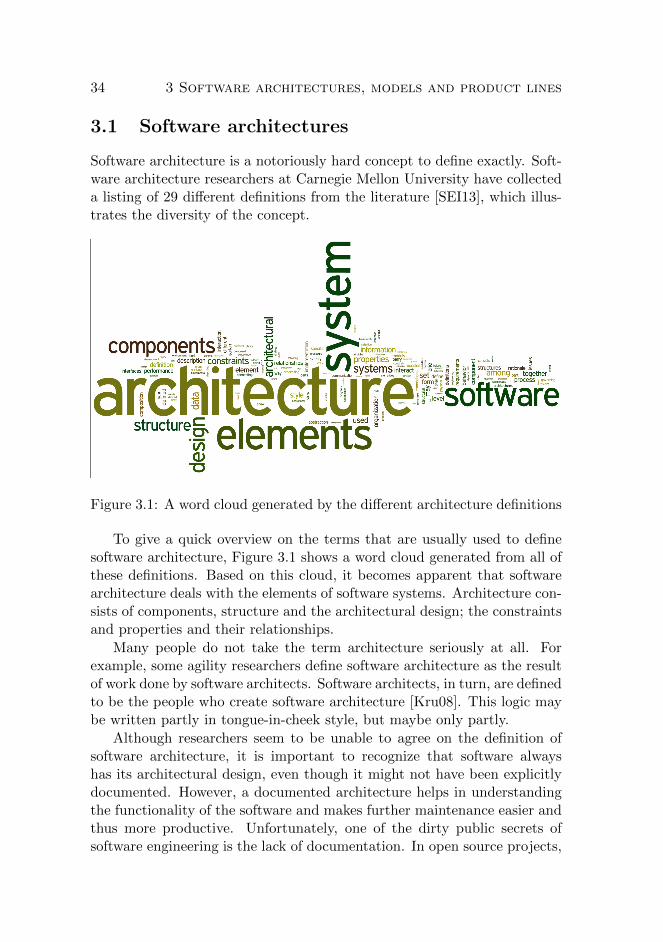
34 3 Software architectures, models and product lines
3.1 Software architectures
Software architecture is a notoriously hard concept to define exactly. Soft-ware architecture researchers at Carnegie Mellon University have collecteda listing of 29 different definitions from the literature [SEI13], which illus-trates the diversity of the concept.
Figure 3.1: A word cloud generated by the different architecture definitions
To give a quick overview on the terms that are usually used to definesoftware architecture, Figure 3.1 shows a word cloud generated from all ofthese definitions. Based on this cloud, it becomes apparent that softwarearchitecture deals with the elements of software systems. Architecture con-sists of components, structure and the architectural design; the constraintsand properties and their relationships.
Many people do not take the term architecture seriously at all. Forexample, some agility researchers define software architecture as the resultof work done by software architects. Software architects, in turn, are definedto be the people who create software architecture [Kru08]. This logic maybe written partly in tongue-in-cheek style, but maybe only partly.
Although researchers seem to be unable to agree on the definition ofsoftware architecture, it is important to recognize that software alwayshas its architectural design, even though it might not have been explicitlydocumented. However, a documented architecture helps in understandingthe functionality of the software and makes further maintenance easier andthus more productive. Unfortunately, one of the dirty public secrets ofsoftware engineering is the lack of documentation. In open source projects,

3.2 Model-driven software engineering 35
people asking for documentation are usually answered ’RTSL’ 1.
The problem lies in the area of duplication: when software is beingchanged, the primary locus of activity is to get the software working in theanticipated way. Updating of the documentation might get done, if timepermits. Most often it does not.
In the past, a number of attempts to salvage the situation have beendone. For instance, literate programming [Knu84] was proposed as a wayto write such clean code that the documentation could automatically begenerated from it. A more recent attempt is to make the artifacts previouslyintended primarily for documentation to be the actual source code. Thisturns our attention to model-driven software engineering.
3.2 Model-driven software engineering
In the past, raising the level of abstraction has been a successful approachto many software engineering problems. Model-driven software engineer-ing is a further step in this direction. The idea is to allow majority ofdevelopers to concentrate on the task at hand, without the need to need-lessly pay attention to technical, low-level details. This is supposed to yieldimprovements in three areas [BCT05]:
1. Productivity – developers can solve business problems faster.
2. Quality – use of automation results in more consistent outcomes.
3. Predictability – standardized transformations help to build a pre-dictable development process.
Models are used in various forms. The most obvious form is the tra-ditional boxes-and-arrows type of modeling, in which graphical notation isused to present concepts or ideas and relationships between them. In soft-ware engineering, currently UML is the most often used language for graph-ical representations of the developed software [Kro03, GKR+07]. However,the concept of modeling is not limited to drawing pretty pictures to thewhiteboard or into a CASE tool - actually the opposite. Some academicsdare even to say that UML is the worst thing to happen to model-drivendevelopment [Coo12] due to a number of reasons: It works on the same levelof abstraction as program code; the fixed number of diagram types does notprovide enough coverage; the language is too complex, but not expressiveenough; the division of platform-independent models and platform-specific
1read the source, Luke

36 3 Software architectures, models and product lines
models is misguided and finally UML makes people to believe that modelsmust be graphical [Coo12].
Models can also be presented in a textual form [GKR+07]. A num-ber of benefits for both the language user and the language developer havebeen identified, including denser information content, speed of model devel-opment, easier integration between languages, platform independence andeasier interoperability with version control systems, to name a few. Anempirical study comparing the use of textual and graphical models foundthat participants who predominantly used text scored significantly betterin communicating software architecture design decisions [HKC11].
The choice between graphical and textual modeling languages is nota mutually exclusive question. Both can be used at the same time. Forexample, the UML standard includes an XML-based format for model inter-change called XMI [OMG07]. Although the graphical elements of UML areoften first cited, the language’s constraint rules language OCL [WK03] isprimarily a text-based language. Thus, UML is actually a hybrid language.Researchers have produced prototypes for other kinds of graphical/textualmodel interaction as well [EvdB10].
Another, important architectural choice is the division between externaland internal models. The normal interpretation is that models are externalto the architecture of a software. In external modeling, the model artifactsare developed in an external tool and are incorporated into the software bythe means of manual, semiautomatic or automatic translation.
When using internal modeling, the model is built as part of the soft-ware’s architecture. For example, object-oriented modeling being done onthe abstraction level of a programming language, using the programminglanguage as the sole notation is an example of using an internal model-ing language. One example of this approach is well documented as thedomain-driven design paradigm [Eva03]. Other examples of internal mod-eling include the use of domain-specific languages.
Model-Driven Architecture
Model-driven architecture [MM03] approaches reusability by separatingconcepts into three layers: platform independent model (PIM), platform-specific model (PSM) and program code. Traversal between these layersis done via transformers: a platform independent model is translated to aplatform-specific model by using a transformer, which augments the modelwith platform-specific attributes. A similar transformation is applied whentranslating the PSM into program code.
A typical platform independent model is expressed as a UML class di-

3.2 Model-driven software engineering 37
Transform2Javapublic class Customer { private int ID; private Date creation; public String name; public String address; ...Transform2SQLDDL
CREATE TABLE customer ( ID INTEGER primary key, CREATION TIMESTAMP not null, NAME VARCHAR(30), ADDRESS VARCHAR(45));
+Name: String+Address: String
Customer
Customer(ID)getName: StringsetName(String)getAddress: StringsetAdderss(String)
- ID: integer- Creation: Date+Name: String+Address: String
CustomerTransform2EJB
PIM PSM Code
Figure 3.2: A UML model with transformations to Java and SQL
agram which contains only class attributes, possibly with programminglanguage-level visibility information and data type annotations. A trans-formation creates corresponding programming language, e.g. Java classes,with accessing methods for each of the public attributes, or data-definitionstatements for a relational database.
Figure 3.2 represents a typical case, in which a highly abstracted classmodel (PIM) expressed in UML is first transformed to a platform-specificclass model (PSM). In this transformation, the class is augmented withplatform-specific features, such as accessor methods and constructors. Thismodel is then further transformed to programming language code by thenext transformation. Yet another transformation generates the correspond-ing database definition.
These transformations contain target-specific parametrization, as thetransformation contains information about the target platform. In theUML-to-Java transformation, UML standard visibility rules are followed,but a data type transformation from UML integer to Java int is performed.In the UML-to-SQL transformation, similar platform-specific knowledge isbeing encoded. Most notably, the transformations also contain informationabout the system that is not shown in the source model. For example,the knowledge about different field sizes for Name and Address that havethe same data type in the source model is encoded into the UML-to-SQLtransformation.
Two distinct interpretations of using model-driven architecture toolshave been identified. The first is the elaborationist approach [KWB03], inwhich the idea is not to even try to provide a complete set of operationaltransformations. Instead, the models are used as an initial kickstarting set,and the transformers produce a skeleton of the produced software. After

38 3 Software architectures, models and product lines
the initial generator run, programmers take over and do further modifica-tions by hand. Obviously, this approach entails the round-trip engineeringproblem, since the initial models are useless after a few modifications tothe generated code.
The second interpretation is the translationist approach [MB02], inwhich the target is to have the human modeler to work only in the modelworld and translations then generate the whole application. This is done,for instance, by introducing a new UML profile with a defined action se-mantics that is used in the application generation. This approach highlightsone of the most fundamental problems with model-driven architecture: theinflexibility of toolsets and the (morbid) rigidity of extensions.
A notable shortcoming in using UML class diagrams to express theplatform independent models is lack of extensibility [FGDTS06, SB05]. Aclass diagram can directly express only a limited set of parameters, suchas visibility, data types, and default values. Further extensions requireusing UML profiles. A number of proposals for using profiles to expressvariability have been presented, e.g. [PFR02, KL07].
The problem with UML profiles relate to tool support and decreasedinteroperability and the dominance of chosen modularity. First, profilesmay or may not be supported by the used toolset; toolset immaturity isone of the problems identified in the model-driven engineering literature[MD08]. This leads to decreased interoperability, as transferring modelsfrom one tool to another may lead to very unexpected results.
Poor interoperability between different tools is a problem related totoolset immaturity. The model interchange format XMI does specify howto define elements on the abstract level, but e.g. diagram layout is stillbeing implemented via vendor-specific extensions [SB05]. Currently, toolinteroperability is being built as point-to-point connections, e.g. by buildinga bridge from Eclipse to Microsoft modeling tools [BCC+10].
Other problems rise when trying to find the correct level of abstraction.For example, not all semantic connections in the source models are suitablefor automatic transformations [BCT05]. Lack of automatic transformationsis a big problem, since the initial promise of improved productivity is builton top of automation shoulders. Some researchers overcome this limitationby extending the base programming language to better accommodate formodel-code interaction [SKRS05].
Another problem identified in the literature is the change in applicationstructure: with the introduction of models, model transformations andcode generation, the application logic is scattered to various places in thearchitecture [SB05]. This is argued to hinder general understandability of

3.2 Model-driven software engineering 39
the system, and thus to hinder maintenance.
Yet another problem is that given the current fast rate of change intechnology choices and architectural evolution in software engineering, themodel transformations provided by the chosen toolset probably do notmatch the current architectural needs of the developed software [SB05].When this occurs, the development team has two choices: try to find an al-ternative, better suiting toolset or try to improve the existing toolset. Thefirst option basically stalls development work, as the focus has changed tofinding the right tool for the job instead of actually doing the job. Thesecond alternative, if viable at all due to copyright reasons, requires spe-cialized personnel who have the ability to modify the transformations usedby the toolset. Since the development of the actual software cannot bedelayed, the software’s architecture evolves in parallel to transformationdevelopment. This reason gives a good chance that any given set of modeltransformations is already obsolete at its completion time.
It is also noted that in practice model-to-model mappings are complexand require careful design and implementation [BCT05]. While all softwareengineering needs careful design and implementation, it seems to be an evenmore relevant problem in the context of model-driven software engineering.
In conclusion, given these reasons, unconstrained usage of model-drivenarchitecture cannot be considered to be a good match for current agile de-velopment environments. However, we do not propose to canonically rejectsoftware development based on model-driven architecture. Our critiqueprimarily bases on the combination of short-lived sprints of agile develop-ment and the uncertainty of toolsets and practices promised by MDA toolvendors. In cases where a toolset’s abilities and limits are well known inadvance, using the toolset-driven approach can be beneficial even in tightlytime-framed situations.
Support for evolution in model-driven engineering
Support for evolution is often a recurring question in different flavors ofmodel-driven engineering (MDE). Model-driven engineering is a larger con-cept than the model-driven architecture discussed in the previous chapter:MDA refers to the reference implementation that is trademarked by ObjectManagement Group. Model-driven engineering refers to the general idea ofusing higher level models to drive software engineering.
The first rule in the MDE context is that developers are not supposedto modify the artifacts generated from models [SB05]. This is conceptuallynot a new idea, since in the classical edit - compile - run developmentcycle, engineers are not supposed to manually modify the assembler code

40 3 Software architectures, models and product lines
generated by the compiler. However, since some model transformationsgenerate high-level programming language code, it seems to raise someconfusion about the role of the generated artifacts.
Why would there be need to manually modify generated code in a soft-ware project? The reasons can be manyfold. Examples include the lack ofsemantical expressiveness in the source modeling language; non-optimizingtransformations that produce sub-optimal target code with the consequenceof performance problems; or just plain lack of required expertise in theproject personnel.
For any tools that are targeted to real-world use, the need to supportsoftware evolution is not a new requirement. However, tools support thisneed using different approaches. For example, the AndroMDA tool empha-sizes the use of subclassing for modifications [SB05]. This approach followsthe ”Generation Gap” pattern [Vli98, p. 85-101]. In some cases, this canbe adequate, but a number of cases can be identified where inheritance isnot good enough. For example, a study on scalable extensibility presentscases where inheritance is not a good choice for extending a set of classeswhen the corresponding objects interact in a certain way [NCM04]. Otherexperts complain about the lack of inheritance expressiveness [Lie86] andabout the potential misuse of inheritance hierarchies [Tai96]. Also, it can beproblematic to use inheritance when reusing and extending interdependentclasses. It can be argued that the class hierarchies become unnecessarilybig if all the generated classes have automatically generated base class, andthe corresponding editable subclass.
In Paper (II) we describe an extension of the Visitor pattern [GHJV95,p. 331-344] for a set of generated classes. The Walkabout pattern [PJ98]uses reflection facilities to adjust the orchestration of visited nodes. Weuse its more efficient version called Runabout [Gro03] to generate a cor-responding Visitor base class hierarchy for the corresponding model, andthen rely on the type checking rules in the implementation language forfinding inconsistencies introduced by evolutionary changes in the system.
Although the principle of not manually modifying generated code iswell accepted in general, many researchers in the model-driven engineeringcommunity fail to take evolution into account. For example, a recent studydescribes a system for generating web applications based on a self-grownmodeling language [BLD11]. The description does not support further evo-lution of the system: any changes to the system require a full re-generationof the produced software. As such, the approach can be classified to fall intothe translationist category of the two model-driven engineering approaches.However, combined with the lack of expressiveness in the source modeling
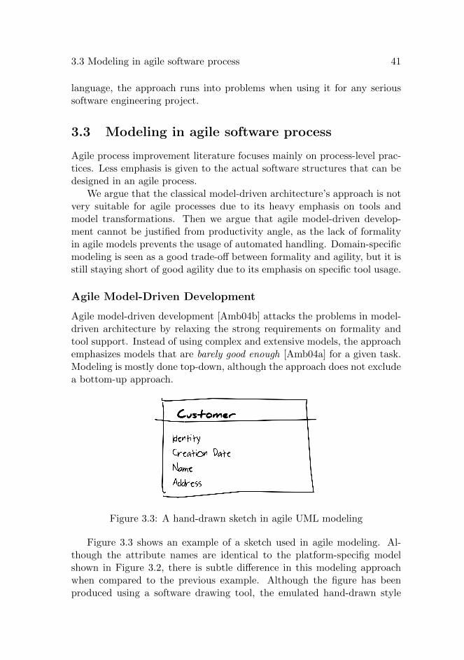
3.3 Modeling in agile software process 41
language, the approach runs into problems when using it for any serioussoftware engineering project.
3.3 Modeling in agile software process
Agile process improvement literature focuses mainly on process-level prac-tices. Less emphasis is given to the actual software structures that can bedesigned in an agile process.
We argue that the classical model-driven architecture’s approach is notvery suitable for agile processes due to its heavy emphasis on tools andmodel transformations. Then we argue that agile model-driven develop-ment cannot be justified from productivity angle, as the lack of formalityin agile models prevents the usage of automated handling. Domain-specificmodeling is seen as a good trade-off between formality and agility, but it isstill staying short of good agility due to its emphasis on specific tool usage.
Agile Model-Driven Development
Agile model-driven development [Amb04b] attacks the problems in model-driven architecture by relaxing the strong requirements on formality andtool support. Instead of using complex and extensive models, the approachemphasizes models that are barely good enough [Amb04a] for a given task.Modeling is mostly done top-down, although the approach does not excludea bottom-up approach.
Figure 3.3: A hand-drawn sketch in agile UML modeling
Figure 3.3 shows an example of a sketch used in agile modeling. Al-though the attribute names are identical to the platform-specifig modelshown in Figure 3.2, there is subtle difference in this modeling approachwhen compared to the previous example. Although the figure has beenproduced using a software drawing tool, the emulated hand-drawn style

42 3 Software architectures, models and product lines
suggests that the intent of the model is to enable communication and col-laboration. This is in contrast to the technical representation used in theprevious example.
According to this philosophy, created models should not affect theagility principles of a given process. As long as a model can be createdand exploited within a production cycle (usually 1-3 weeks), it is suitablefor agile modeling. This is a promising approach, but it does not state muchabout the possible modeling tools - actually, the approach de-emphasizesthe need for tools, and focuses on people.
Due to this requirement, most modeling is based on high-level abstractmodeling languages with little formalism. They are easy to learn, simpleto use and fit well within a given time period. However, they offer more toeasier problem domain abstraction than to automatic productivity increase.To our best knowledge, no productivity-related empirical validation hasbeen done for agile model-driven development.
Model-driven architecture is a top-down approach to software engineer-ing. Due to its heavy emphasis on tools and process, the approach is nota good fit for agile time-boxed iterations. Light-weight models are often abetter alternative in agile development. Boxes and arrows on a whiteboardis a good start. However, we argue that in order to realize productivitygains, these models can and should be brought into software architecturelevel entities.
3.4 Software product lines
One answer to demands for easier utilization of software assets in reuse isthe usage of software product lines. In a software product line, the idea isto organize software development into components that can be combinedin defined, different ways. Domain analysis identifies core assets of a prod-uct line, which form a software platform. When needed, product-specificcomponents can be included into a single product [LSR07, p. 6-8].
The aim of a software product line is to be able to support a number ofdifferent software products that share certain commonality between them.Typical examples of software product lines have emerged in areas of embed-ded software, such as cell phones [LSR07, Chapter 12] or avionics software[DBT11].
The starting point for defining the ways of possible combinations is themodeling of variability. Many variability modeling formalisms are built ontop of feature-oriented domain analysis, FODA [KCH+90].

3.4 Software product lines 43
Modeling variability
Feature modeling [KCH+90] is a formalized way of building option spaces.The formalism allows to define structures with mandatory features, optionalfeatures and combinations of them.
A canonical example of using feature modeling was presented in [CE00].The example elaborates on all basic operators in basic feature modeling.The model defines an option space for a car, which is shown in Figure 3.4.The car needs to have the body, the transmission, and the engine. Thetransmission can alternatively be automatic or manual. The engine can beelectric or gasoline driven, or both. Optionally, there can be a trailer pullinghook. The original explanation of the formalism is mathematically rigorous.Fortunately, other introductory texts such as [AK09] kindly remind readersof the practical implications of the constructs, by associating the words xorand or to the optionality operators, as shown in the figure.
Figure 3.4: A feature model of a car [AK09]
Given this option space, the following 12 distinguishing configurationssatisfy the model:
1. Transmission: Automatic Engine: Gas2. Transmission: Automatic Engine: Electric3. Transmission: Automatic Engine: Gas+Electric4. Transmission: Automatic Engine: Gas Pulls Trailer5. Transmission: Automatic Engine: Electric Pulls Trailer6. Transmission: Automatic Engine: Gas+Electric Pulls Trailer7. Transmission: Manual Engine: Gas8. Transmission: Manual Engine: Electric9. Transmission: Manual Engine: Gas+Electric10. Transmission: Manual Engine: Gas Pulls Trailer11. Transmission: Manual Engine: Electric Pulls Trailer12. Transmission: Manual Engine: Gas+Electric Pulls Trailer
More advanced feature modeling variations allow the use of cardinalityconstraints, cross-tree constraints [Bat05], default values [SBKM09] and

44 3 Software architectures, models and product lines
other extensions.
In the example of Figure 3.4, a natural cross-tree constraint could bethat when the trailer pulling option is selected, there needs to be a gasengine - a pure electric engine would not suffice for the added load ofpulling the trailer. This could be expressed as Pulls Trailer implies GasolineEngine. This constraint would rule out the configurations #5 and #11, thusreducing the number of valid configurations to ten.
The usage of default values allows the model to be augmented withguides on which values should be chosen if no additional information isgiven. In the example, the default values could be Manual Transmissionand Gasoline Engine, which would result the configuration #7 to act asthe starting point of engineering.
The example in Figure 3.4 represents a case where the software’s datais modeled using feature modeling. However, the internal features of asoftware can also be modeled with the same mechanism. For example, theLinux kernel contains a domain-specific language, Kconfig, for configuringthe features to be used. An example of the Kconfig model is given in Figure3.5.
The excerpt of the actual kernel file linux-3.6/arch/mips/Kconfig is usedto configure the kernels targeted to the MIPS processor architecture. Thedefault target is the IP22 prompt, which was used in the once-popular SGIIndy machines. The alternative in the figure is IP27, which was used in alater models of Origin 200 and Origin 2000.
This small fragment of the feature model shows how the Kconfig lan-guage can be used to express alternation (choice), defaults (default), datatypes (bool), and cross-tree dependencies (depends) when configuring thekernel options to be used. The expressive power of the language providesfor feature models with cross-tree constraints and default values [SLB+10].However, as models in the language are involved with end-user interactiveconfiguration software, it also contains instructions for displaying user helptexts and other usability aiding tools.
To help in seeing what kind of support variability modeling can bringfor software developers, researchers have started collecting an on-line repos-itory of published variability models [MBC09]. This repository contains atthe time of writing a collection of over 300 known, published models ofvariability in different domains and can be used to get a concrete feeling ofhow software variability modeling is currently being done.
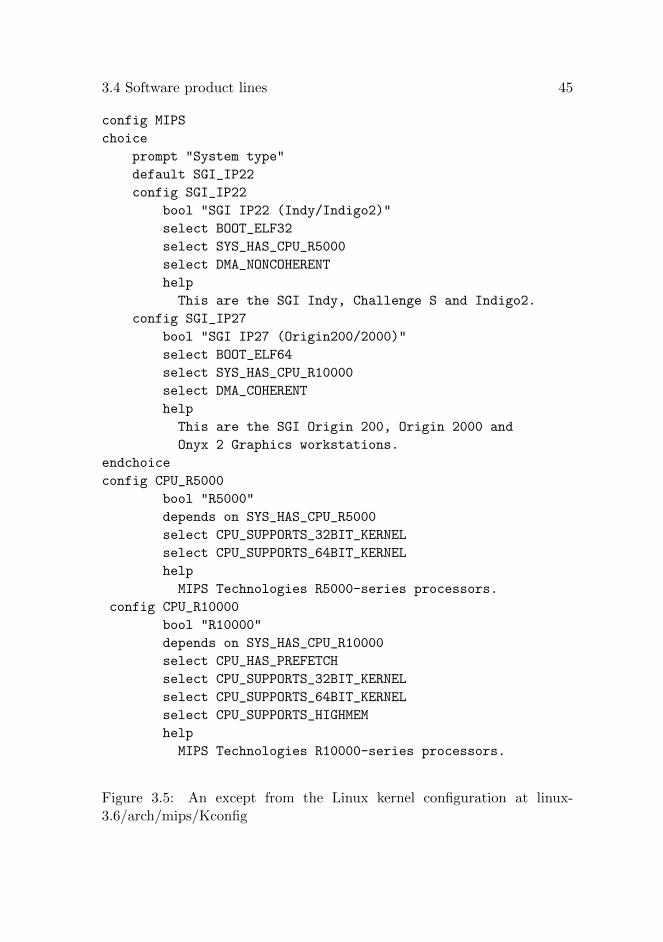
3.4 Software product lines 45
config MIPS
choice
prompt "System type"
default SGI_IP22
config SGI_IP22
bool "SGI IP22 (Indy/Indigo2)"
select BOOT_ELF32
select SYS_HAS_CPU_R5000
select DMA_NONCOHERENT
help
This are the SGI Indy, Challenge S and Indigo2.
config SGI_IP27
bool "SGI IP27 (Origin200/2000)"
select BOOT_ELF64
select SYS_HAS_CPU_R10000
select DMA_COHERENT
help
This are the SGI Origin 200, Origin 2000 and
Onyx 2 Graphics workstations.
endchoice
config CPU_R5000
bool "R5000"
depends on SYS_HAS_CPU_R5000
select CPU_SUPPORTS_32BIT_KERNEL
select CPU_SUPPORTS_64BIT_KERNEL
help
MIPS Technologies R5000-series processors.
config CPU_R10000
bool "R10000"
depends on SYS_HAS_CPU_R10000
select CPU_HAS_PREFETCH
select CPU_SUPPORTS_32BIT_KERNEL
select CPU_SUPPORTS_64BIT_KERNEL
select CPU_SUPPORTS_HIGHMEM
help
MIPS Technologies R10000-series processors.
Figure 3.5: An except from the Linux kernel configuration at linux-3.6/arch/mips/Kconfig

46 3 Software architectures, models and product lines
Implementing variability
Implementing variability in a software product or system has many alterna-tives. However, before discussing about variability implementation mecha-nisms, the target of variability needs to be clarified. The model shown inFigure 3.4 represents a domain-analysis part of feature modeling: it couldbe contained for instance in a software system that manages purchase or-ders to a car factory. Another way of using feature modeling is to modelthe software structure, as is done in Figure 3.5.
In Paper (I) we present a case where software variability for differentplatforms is implemented by the means of object-oriented interfaces. InPaper (III) the discussion targets to implementing domain-analysis part ofthe model.
On software architecture level, the variability can be implemented witha number of techniques. Alternatives for implementation include at leastthe following:
• conditional compilation
• object-oriented composition
• aspect-oriented composition
• external rules engines
• generative scripting
In the following, we will shortly review these techniques.
Conditional compilation
Conditional compilation, also known as #ifdef s, is a widely used imple-mentation mechanism of variability. In conditional compilation, the sourcecode contains various preprocessor directives that are used to select outsome parts of the unpreprocessed source. The variability-processed sourceis then fed to the regular compiler.
In the Kconfig context, this works as follows. Each configuration direc-tive in the Kconfig files is exposed to the preprocessor by setting the CON-FIG - variables where the name of the configuration directive is appended tothe preprocessor variable name. e.g. CONFIG DMA NONCOHERENT.Not all configuration directives are used in the source code, but some ofthem act as purely variables for guiding the configurational structure. Forexample, the SYS HAS CPU R5000 preprocessor variable does not appearanywhere in the source code.

3.4 Software product lines 47
For example in the Linux kernel 3.6, a part of the file arch/mips/mm/c-4k.c reads as shown in Figure 3.6.
void __cpuinit r4k_cache_init(void)
{
[..]
#if defined(CONFIG_DMA_NONCOHERENT)
if (coherentio) {
_dma_cache_wback_inv = (void *)cache_noop;
_dma_cache_wback = (void *)cache_noop;
_dma_cache_inv = (void *)cache_noop;
} else {
_dma_cache_wback_inv = r4k_dma_cache_wback_inv;
_dma_cache_wback = r4k_dma_cache_wback_inv;
_dma_cache_inv = r4k_dma_cache_inv;
}
#endif
build_clear_page();
build_copy_page();
coherency_setup();
}
Figure 3.6: Excerpt from the Linux kernel source file arch/mips/mm/c-4k.c
In the excerpt, the DMA NONCOHERENT selection in the configura-tor tool is shown as a compiler preprocessor directive variable. Choosingthe R5000 processor implies the DMA NONCOHERENT selection to bechosen as well, which leads to inclusion of the #ifdef part in the actualcompilation cycle. In the case of the R10000 processor, this part is left out.
Using preprocessor directives has been the way to do parameterizedcompilation long before software product lines were invented. However,since conditional compilation is well supported in toolchains and the con-cept is well understood among software developers, it is an often used tech-nique for implementing software product lines as well.
On the other hand, the simultaneous handling of configuration timeand compilation time constructs hinders code understandability. Labeledas #ifdef hell [LST+06], software developed to be parameterized throughconditional compilation is known to be harder to understand than soft-ware that does not use it. If not attributed by using other implementationmechanisms, the problem can be relaxed e.g. by improving tool support

48 3 Software architectures, models and product lines
[FKA+12].
Object-oriented composition
In object-oriented composition, interfaces are a natural point of variation.An interface class represents a variation point, and variability is imple-mented by changing the concrete implementation of the interface.
In paper (I) we demonstrated and empirically tested an optimizing com-piler that works on a software product line using interfaces and abstractclasses as the means to differentiate between mobile phone models. Inthe research setting, the overhead introduced by object-oriented constructswas feared to become preventive for employing good software architectureprinciples with suitable abstractions.
Some researchers believe that this kind of support for program evolu-tion cannot be supported in resource-constrained environments [ZHKH07,ZHK07]. However, this view is based on incomplete understanding of theapplication building process: variability that is resolved before deploymenttime does not bring any runtime overhead.
Aspect-oriented composition
In aspect-oriented programming [KLM+97], the base software augmentedwith optional aspects. Specific weaving expressions that define the joiningpoints are used to guide where the optional aspects should be inserted atcompilation time or at runtime.
These join points can be used as the variation points: when an op-tional feature should be present by the product line configuration, the cor-responding aspect is woven to the base software. Examples of this kind ofimplementation can be found at [AM04] and [GV09].
External rules engines
In some cases, the software product line is not implemented in the coresoftware’s architecture at all. Instead, the variation is outsourced to anexternal rule engine: all variation is expressed by changing the rules in theengine.
This approach has the benefit of moderating the changes to softwarearchitecture required by different customers and variations of the software.All the changes are encapsulated to their own environment.
The drawback in this approach is that the degree of variation is limited:the number of variation points is limited to the points where the basesoftware transfers control to the external engine. Variation obviously is not

3.5 Self-organizing and self-configuring software architectures 49
a first class entity in the architecture. Also, the question of how well theexternal engine supports variation is not answered in this approach: shouldthe rules in the engine follow some variation approach presented in thischapter, or is all the variation implemented using ad hoc implementationtechniques?
Generative scripting
Generative scripting is another approach to implementing product lines. Inthis approach, the idea is to use a higher level model as the product linedefinition. Scripts are then used to generate corresponding lower-level code,very much in the style of model-driven engineering presented in Section 3.2.Much of the discussion from that section applies to using models to drivesoftware product line engineering as well.
An example of this kind of architecture is the generation of the NH90 he-licopter product line, which has customers in several countries and military-grade restrictions in letting one country’s version to interact with anothercountry’s version [DBT11]. In this environment, the big boost for pro-ductivity is the standard certification requirement in the avionics softwaredevelopment. In avionics software development, the created software needsto be certified by aviation authorities before it can be included in a type-certified aircraft. Standard object-oriented techniques, such as dynamicdispatching based on late binding, are known to be problematic to get cer-tified due to their unknown runtime properties. In the NH90’s case, thedevelopers were able to certify the code generating Perl script as a way todo static dispatching at development-time binding.
3.5 Self-organizing and self-configuring softwarearchitectures
Both model-driven engineering and software product lines are approachesto resolve problems introduced by software variation. Variability can hap-pen over time – i.e. software evolution – and over different contexts, such asvariations tailored to different customers or product models. These tech-niques can help to manage the complexity introduced by variability, butmany open problems still reside.
Self-organization is a way to reduce or minimize the need of explic-itly managing the organized elements. For software architectures, self-organization has been applied in context of dynamic component discov-ery [MK96] and distributed systems development [GMK02] while ensuring
50 3 Software architectures, models and product lines
overall system structure consistency.
In this thesis, we propose that using self-organizing software architec-tures is a way to improve productivity and maintainability. These goalsare even more important when addressing problems in several differentcontexts. For example, feature interaction is a core problem in softwareproduct lines: how to understand program behaviour in all possible config-urations in different contexts and how to make sure that the chosen featuresdo not interact in a wrong way.
However, using self-organizing software architectures is not limited tosoftware product lines. They can be used, in general, as a simplifyingtechnique for the architecture. Since the self-configuring components canbe used to remove or reduce duplication, the architecture of a softwarebecomes simpler. Before giving examples of how this is done, we will reviewwhat is meant by self-configuring software components and self-organizingsoftware architectures.
Various kinds of self-something properties have been described for soft-ware systems. For a compact review, a dissection of the different self-*properties can be found in [BG09]. For our discussion, the definitions forself-organizing and self-configuring are the most interesting ones.
For self-organizing systems, a few different definitions exist. Andersonet al. define self-organization to require the system to maintain, or mono-tonically improve a function value involving the neighbors of the joining orthe departing process in-between process joins and leaves [ADGR05]. Asso-ciated properties of self-organization are that the self-organization shouldhappen in sublinear time and process joins and leaves should cause onlylocal changes [DT09].
Now the question is that how does this relate to software architecture?Some parts of distributed software are targeted to handling process joinsand leaves, but certainly it is in the core of software architecture only in fewof the above mentioned definitions. To transfer these process-centered defi-nitions, we should focus on the concepts in the software architecture: com-ponents, structure, design, constraints, properties and their relationships.For an architecture to be self-organizational, there should be a mechanismfor maintaining or monotonically improving the software when new archi-tectural elements are added, or old ones are removed or modified.
Self-configuration of a software system, in turn, refers to the ability to”change its configuration to restore or improve some [safety] property de-fined over configuration space” [BG09]. When comparing self-configurationand self-organization, the former requires the system to change its config-uration when restoring, maintaining or improving some property of the
3.5 Self-organizing and self-configuring software architectures 51
system after a change. The latter handles joining or removal of archi-tectural elements. Thus, it follows that every self-organizing system isself-configuring, but the reverse is not true [BG09].
When discussing the joining and leaving of architectural elements, weneed to think about the binding time of decisions. A usual division ofbinding times is to talk about design-time, coding-time, compilation-time,deployment-time and runtime decisions. For example, overall architecturaldesign is clearly a design-time decision while the dynamic binding of methodcalls in an object-oriented language is a runtime decision. Choosing thedatabase connection parameters is a typical deployment-time decision andtuning of the database engine to perform with a given workload is oftenruntime work.
Another dimension to the discussion is the amount of human interac-tion needed for making these decisions: fully automated decisions can bemade without human intervention – but often, some kind of human inter-action is needed. For example, in the world of refactorings [Opd92] wecan see a continuum from manual refactorings to automated refactorings[KEGN01]. To be able to safely make automated decisions, they need tobe formally specified: under certain conditions, a certain refactoring canbe made. Stricter formality requirements lead to limited applicability, andoften to a local scope. On the other hand, the amount of possible collateraldamage is also limited. In manual refactorings, there is high possibility forcollateral damage, but they can be widely applied and the human opera-tor (the programmer) can use human judgement to make global changes.Often a high cost is involved due to high wages of programmers, at leastwhen compared to electricity price. When the refactoring steps cannot bespecified with enough precision, maintenance patterns [HH04] can be usedto give the maintenance programmer some guidance on the workings of thesystem.
Figure 3.7 shows a few approaches on formality and binding time axis.Self-organizing software architectures are such software architectures thatcan adjust their functionality to changes in the architecture, such as addingor removal of components in the software. By definition, self-organizationhappens at late binding time: adjustments to the architecture at designand coding time are refactorings rather than examples of self-organization.
Application-level self-organization can be implemented by using self-configuring components. A self-configuring component contains programlogic for adjusting the functionality of the component according to its localenvironment. In Paper (V) we show an example of a self-configuring com-ponent of database queries. Without such self-configuring component, the

52 3 Software architectures, models and product lines
Form
ality
Binding time
Fullyautomatable
Humandecisioninvolved
Designtime
Codingtime
Deploymenttime
Runtime
Manual refactoring
Automatedrefactoring
Database tuning
Maintenancepatterns
Self-organizing software
Compilationtime
Figure 3.7: Chart of formality and binding time applicability of differentmodifications
database querying layer would need its own components for all databasequery contexts. These can be replaced by one self-configuring componentwhich adjusts its functionality according to each context, thus simplifyingthe architecture.
These kinds of improved modularity and maintainability properties areuseful in all software engineering, but they are especially useful when the re-sulting software experiences regular modifications, e.g. as is done in model-driven engineering when changing the model and in software product lineswhen deriving different variations out of the product line.
When designing a self-configuring component, the implementation needsreflectional access (self-description) to the context that the component isadjusting itself to. When the access is implemented via source code orother low-level access mechanisms, it can become cumbersome to design ef-ficient self-configuration. If the accessed software exposes its functionalityin higher level models, this task can become easier. In the next chapter wewill explore bottom-up modeling, which can be used to overcome an oftenexperienced conflict between high-level models and low-level implementa-tion details.

Chapter 4
Bottom-up modeling
Model-driven architecture in its various forms gives a principle for increas-ing software development productivity by raising the level of abstraction.Model-driven development concentrates on models of the domain, thus al-lowing developers to concentrate on the actual domain instead of fightingagainst the compiler on the programming language level. However, tra-ditional model-driven approaches are rather heavy-weight, as they requireintensive support from various tools before meta and meta- meta-level con-structs are defined precisely enough to be used. The end result appealsto architectural enthusiasts, also known as architectural astronauts [Spo04,pp. 111-114], but is seldom good enough for real software development.
The following sections are organized as follows. Section 4.1 briefly dis-cusses why top-down modeling is problematic, especially in agile context.Section 4.2 represents the alternative: modeling in a bottom-up way. Sec-tion 4.3 explains the bottom-up modeling concept with an example in con-text of building a data model for general aviation maintenance application.Section 4.4 discusses when the bottom-up modeling approach is applicablein software development. Section 4.5 reviews related work.
4.1 Problems of top-down model engineering
When starting modeling in a top-down fashion, it is often unclear whetherthe chosen modeling formalism can handle the task. If the formalism is tooweak, modelers cannot express their intentions well enough. For example, ina critique of MDA, researchers found out that plain UML is not expressiveenough for software development. Tools use vendor-specific profiles, whichlimits interoperability and can cause vendor lock-in [SB05]. On the otherhand, if the formalism is too strong, it is probably also too complex. This
53

54 4 Bottom-up modeling
steepens the learning curve and makes modeling less lucrative.
The top-down approach assumes a complete and correct understandingof the system being developed. This is seldom the case in software devel-opment. An early advice for software engineering once stated that buildone to throw away [Bro95]. Following this route can help in building un-derstanding of what is needed to build the system. Unfortunately, withthe current demands of faster time-to-market, only few teams can afford tospend extra time in the beginning to build something that is going to bethrown away anyway.
Another problem is that with the top-down approach, the referred de-signs are treated as ’black boxes’ that are to be further specified and de-veloped in the following step-wise refinements. The black boxes may fail toclarify the internal workings of fundamental elements in the lower abstrac-tion level [EHS10, p. 34]. For an uninitiated designer, the seemingly simplestructure can then turn out to be unimplementable at the lower level.
4.2 Bottom-up model-driven engineering
To overcome difficulties with the top-down approach, it is often possible tochange to a bottom-up approach. Traditional model-driven engineering isessentially a top-down method, which recursively decomposes the problemto smaller pieces, until any given piece is small enough to be solved withavailable tools. The alternative to top-down methods is to use a bottom-upapproach which identifies smaller sub problems and develops solutions tothese. When this cycle is repeated, gradually the solution for the wholeemerges. Given a problem domain, the bottom-up approach identifies sub-domains that are amenable to modeling.
Bottom-up model driven development [BS13] recognizes the problemsof working with abstract artifacts that hide the concrete results of the mod-eling work. They propose to change the point of view from fully synthesiz-ing model-driven software development to use partial models and partialsynthesis. Where-ever a model is recognized to be useful, based on un-derstanding gained from working with concrete code elements, higher levelmodels can be developed. Since the models do not comprise the wholesoftware, the generated code is also based on partial synthesis.
Agile bottom-up modeling constrains the model identification processto such tools and techniques that can be applied in an agile process model.The application of bottom-up modeling is thereby limited to a small numberof tools, which can be evaluated and applied within a tightly time-boxediteration. Yet, although this search-and-discover approach theoretically

4.2 Bottom-up model-driven engineering 55
produces non-optimal solutions, it guarantees that progress is not stalledwhile searching for the optimal solution. This way, a bottom-up approachto modeling can avoid the heavy up-front planning phase associated withtraditional model-driven engineering. The need to build complex modelinglanguages with associated tool support can be avoided or the impact of thetool-building effort can be damped to be included within the time-boxedsprints. To further help, existing languages can be reused or a domain-specific modeling tool can be used. The obvious downside of the approachis that repetitive application of ad-hoc modeling constructs might graduallyerode the software’s overall architecture.
The main message with bottom-up modeling is to constantly look forsub-domains that are amenable to lightweight formalization. Crafting meta-models and tools for such a small domain is definitely easier than buildingan all-inclusive supermodel of the whole world, which is argued to be neededin the case of top-down model-driven engineering [BJV04].
We argue that productivity gains chased with model-driven engineer-ing should be combined with agile development models by examining theproductivity problems that are encountered on project level. If a given pro-ductivity problem gives a feeling that its root cause is associated with theproblem of lack of abstraction, or incorrect level of abstraction, then thatparticular part of the software could be a possible candidate for building ahigher level model.
We call this approach as bottom-up agile model-driven development(BUAMDD). In this approach bottom-up models are a way to introducelight-weight (possibly formal) modeling to an agile development process.
Traditional model building deals with object-oriented models, repre-sented in the source code using the implementation language’s abstractionmechanisms. The Model-View-Controller [Ree79] design pattern, maybedecorated with the Fluent Interfaces pattern [Fow10], is a classical exam-ple of this approach. The problem with object-oriented modeling residesin the lack of increased abstraction: the level of handling is essentially thesame as the implementation language’s level of abstraction – and breakingthe productivity barriers induced lack of abstraction is the primary reasonfor applying formalized modeling.
An essential requirement of bottom-up modeling in an agile project isthat the building of model languages and models can be decomposed intosprintable form. We mention both model languages and models becausethe essence of bottom-up modeling is to find suitable abstractions to theproblem at hand, and often this means inventing a new language or reusingan existing language for modeling. This notion is contradictory to the com-

56 4 Bottom-up modeling
mon wisdom of using the best existing tool for the job at hand. However,given the large number of different tools and techniques available on themarket, it is not possible to carry out a thorough tool evaluation withinthe time frame of an iteration. For this reason, agile teams often need tobuild their own abstractions for modeling.
These abstractions or languages are not necessarily complex, meaningthat there is no mandatory need to building complex modeling languageswith associated tool support. Instead, existing languages can be piggy-backed and reused as is common with domain-specific languages [MHS05].Preliminary research shows that this can be the most efficient way to im-plement domain-specific languages [KMLBM08], meaning that it can bea good fit in an agile environment. Also a domain-specific modeling toolcan be employed, once an initial understanding of the problem at hand hasemerged.
Bottom-up modeling does not limit the format of source models, as longas they are expressible in machine-readable form. This means that themodeling language does not need to be a graphical boxes-and-arrows -typetool. Actually, although the traditional boxes-and-arrows kind of modelingcan be beneficial in the drafting board, the lack of exact interpretation forthe used symbols hinders productivity when forwarding these models toany type of automatic code generation or runtime interpretation.
External domain-specific languages are often used, but an interestingalternative is to use the source code as the source model. In practice,this option is viable because using the source code as the source model forfurther transformations increases robustness against modifications into thesoftware. This option is investigated further in Chapter 5.
4.3 An example
In order to illustrate the idea of using the bottom-up approach to modeling,we build an example case of a general aviation operations software. In thisexample, we have a hypothetical aircraft operator who wants to improveits business efficiency by building an operation supporting software suite.The software suite handles various aircraft of different type that are beingoperated by this business. In the first iteration, we build the data modelfor the aircraft database. In a subsequent iteration we then build a newmodule for handling different configurations of individual aircraft.
Although this section carries on with the motivational example, we referto essential literature along the discussion.
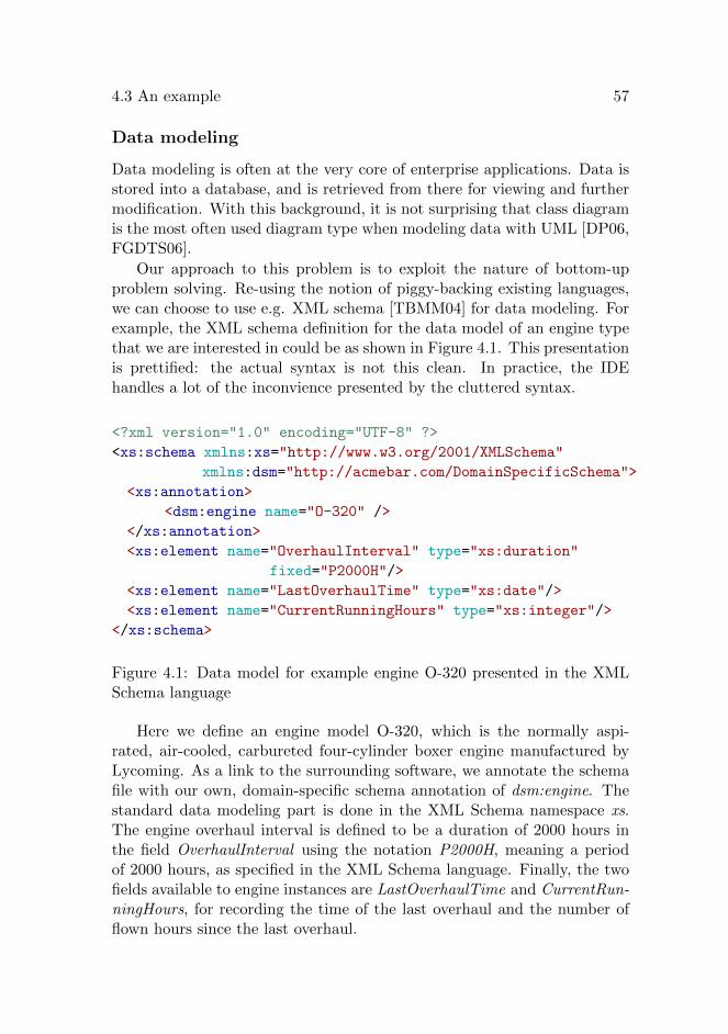
4.3 An example 57
Data modeling
Data modeling is often at the very core of enterprise applications. Data isstored into a database, and is retrieved from there for viewing and furthermodification. With this background, it is not surprising that class diagramis the most often used diagram type when modeling data with UML [DP06,FGDTS06].
Our approach to this problem is to exploit the nature of bottom-upproblem solving. Re-using the notion of piggy-backing existing languages,we can choose to use e.g. XML schema [TBMM04] for data modeling. Forexample, the XML schema definition for the data model of an engine typethat we are interested in could be as shown in Figure 4.1. This presentationis prettified: the actual syntax is not this clean. In practice, the IDEhandles a lot of the inconvience presented by the cluttered syntax.
<?xml version="1.0" encoding="UTF-8" ?>
<xs:schema xmlns:xs="http://www.w3.org/2001/XMLSchema"
xmlns:dsm="http://acmebar.com/DomainSpecificSchema">
<xs:annotation>
<dsm:engine name="O-320" />
</xs:annotation>
<xs:element name="OverhaulInterval" type="xs:duration"
fixed="P2000H"/>
<xs:element name="LastOverhaulTime" type="xs:date"/>
<xs:element name="CurrentRunningHours" type="xs:integer"/>
</xs:schema>
Figure 4.1: Data model for example engine O-320 presented in the XMLSchema language
Here we define an engine model O-320, which is the normally aspi-rated, air-cooled, carbureted four-cylinder boxer engine manufactured byLycoming. As a link to the surrounding software, we annotate the schemafile with our own, domain-specific schema annotation of dsm:engine. Thestandard data modeling part is done in the XML Schema namespace xs.The engine overhaul interval is defined to be a duration of 2000 hours inthe field OverhaulInterval using the notation P2000H, meaning a periodof 2000 hours, as specified in the XML Schema language. Finally, the twofields available to engine instances are LastOverhaulTime and CurrentRun-ningHours, for recording the time of the last overhaul and the number offlown hours since the last overhaul.

58 4 Bottom-up modeling
In top-down engineering, using a predefined data modeling languagehas the consequence of a need to implement corresponding support for thelanguage at the implementation level. For example, UML does not providea concise way of defining the simple options modeled in the XML schemadocument above. By using an existing language, with known implementa-tions, the implementation part is easier since the modeling language alreadydefines the available data types [BM04].
With this approach, the data modeling is done by defining XML Schemamodels. The expressive power of the schema language greatly overpassesthe one offered by standard UML class diagrams [MNSB06]. Another ben-efit is that standard XML tools can be used to validate data transmissions.The semantics of the XML Schema language is well understood. As a formallanguage, the source documents can also be used for further model trans-formations; the schema language contains a well-defined variation pointholder for defining new features for the data modeling tool.
Similarly to traditional model-driven engineering, the data model can bea subject to model transformations, for example to define the correspondingdatabase creation clauses as shown in Figure 4.2.
<?xml version="1.0" encoding="UTF-8" ?><xs:schema> <xs:element name="Name" fixed="O-320" /> <xs:element name="OverhaulInterval" fixed="P2000H" /> <xs:element name="LastOverhaulTime" /> <xs:element name="CurrentRunningHours" /></xs:schema>
Transform2DDL
CREATE TABLE O320 ( ID INTEGER primary key, CREATION TIMESTAMP not null, NAME CHAR(5) not null, OVERHAULINTERVAL INTERVAL not null, LASTOVERHAULTIME DATE, CURRENTRUNNINGHOURS INTEGER);
Figure 4.2: Transformation from XML schema to SQL DDL
However, the use of the model is not limited to development time trans-formations. Since the model is expressed in programmatically accessibleform, it can also be used to drive e.g. user interface generation and inputform validation at runtime.
In Section 3.2 we argued that the limited extensibility of UML classdiagrams is a problem for developing domain-specific semantics. In thisapproach, this limitation can be relieved. The XML Schema language con-tains a specifically designed variation point place in the annotation field.This can be used to elaborate the model with arbitrary extensions, basedon domain-specific needs.
However, the approach is not without downsides either. We argue thatthe predefined set of data types is good for implementation. Now thequestion is what if these data types are not good enough for the given need?

4.3 An example 59
At that point the implementation runs into the same problem as whenusing the top-down approach; the situation needs to be handled separately.Fortunately, given the stronger expressiveness, this case does not happenas often and therefore is less problematic in practice.
Feature modeling
For our discussion, the interest lies in how to implement functionality tohandle these kinds of models. In model-driven architecture, the standardapproach is to use transformations to bring the source model into thestreamline of standard modeling languages. Thus, a transformation fortranslating the feature model into an UML model is needed. Literaturepresents various ways for doing this. Several researchers [CJ01, Gom04,GFd98, CCC+11] have presented different flavours of using stereotypes forrepresenting variability in UML. [VS06] suggests that changes in the UMLmetamodel are needed to fully support variability.
These studies contain many fine points for implementing beautiful mod-els of variability using the standard technologies. However, for practicalsoftware development cases, variability is just one of the dozens, hundredsor thousands issues that a development team needs to tackle. It can beimpractical to start discussing about the academically correct way of im-plementing this variability, since it can be hard to demonstrate how thisdiscussion brings value to the end customer. Due to the economic reasonsdiscussed in Section 2.5, it probably never will.
An alternative is to work with this specific problem, using the standardtools offered by the implementation environment. For the variability ex-ample, in Paper (III) we have documented a way of using standard regularexpressions for modeling variability. This approach tries to combine goodparts from both formal modeling and agile product development. The ap-proach has the benefit that the customer can be shown steady progress,since modeling is concentrated on small subdomains. On the other hand,since the models are implemented using the standard implementation en-vironment structures, the mismatch between modeling environments andimplementation is kept at minimum.
In our example, next we define the semantics of the software conceptaircraft. As an implementation vehicle, we use regular expressions to definethe variability model as shown in Figure 4.3. In this definition, we definewhat different parts can form an airplane. The definition reads as follows:
• The fuselage can be either pressurized or unpressurized.
• There are always two wings, the empennage and the tail.

60 4 Bottom-up modeling
• The propeller is either a fixed pitch or variable pitch.
• The engine type is one of: O-320, TSIO-360 or TAE-125.
• There can be up to 3 radio (COM) units, each with the optional VHFnavigation (NAV) ability.
• There can be navigation equipment group for automatic directionfinder (ADF), distance measuring equipment (DME), VHF omnidi-rectional range (VOR) and global positioning system (GPS).
• The avionics is either the traditional six-pack avionics or a glass-panelG1000 model.
• The landing gear can be either conventional or tricycle.
• The landing gear can optionally be a retractable undercarriage.
aircraft consists of:
(pressurized | unpressurized) fuselage
left wing right wing empennage tail
(fixed pitch propeller | variable pitch propeller)
(O-320 | TSIO-360 | TAE-125) engine
(no | (COM NAV?){0-3}) radio
(no | (ADF | DME | VOR | GPS)+) navigation
(G1000 | traditional) avionics
(conventional | tricycle) gear
(retractable undercarriage)?
Figure 4.3: Variability model of aircraft
In the case of radio and navigation equipment, there is the option ofthe aircraft not having any of these: in that case the ’no radio’ and ’nonavigation’ options are chosen. Each of these elements can contain the cor-responding data model definition. For example, the data model definitionfor the engine O-320 was given in Figure 4.1.
This is a very concise way of using higher level abstraction to bringbenefits of modeling into implementation level. For example, if we wantto validate a given aircraft configuration, we can feed the proposed config-uration to a regular expression matcher, which is available in all modernprogramming languages.
However, using this kind of modeling language specific translation tothe implementation language raises some questions. For example, many

4.3 An example 61
feature modeling formalisms allow the definition of cross-tree constraints.In the example model, we could not specify the linkage between a VHFomnidirectional range equipment and a navigational radio. In a generalaviation aircraft, the VOR display receives navigational signals from theNAV radio. If the aircraft does not contain a NAV radio, the VOR dis-play cannot function either. When using regular expressions to representfeature models, these kind of cross-tree constraints are problematic. Manyprogramming language implementations offer the use of back referencesthat can be used up to some degree. Another option is to implement thecross-tree constraints in general programming language code. One of themain ideas in BUAMDD is to iteratively find the optimal, desired balancebetween the models and the code.
Using UML models gives the possibility to scale the scope of modelingto include also the attributes of modeled entities, for example, if there isa need to specify the size or power of the engine being modeled. In aclass diagram, it is very straightforward to add the attribute in questionto the class model. But using regular expressions to model even five toten different engines would soon prove to be cumbersome. However, thisdoes not mean that we could not extend our little language to a biggerone. Quite the contrary: when we identify the need for such a semanticextension to regular expressions, we can choose to adopt e.g. attributegrammars [Paa95] to handle our increased needs.
How in practice that extension would be implemented depends on theenvironment and individual preferences of the designer. In Section 3.2 wediscussed the difference between internal and external modeling. Usingan external modeling with a dedicated generator/extension suite, such asJastAdd [EH07] could be a good choice in a Java-based environment. Ifthe operating environment happens to have a good support for internalimplementation of attribute grammars, such as the Kiama library in aScala environment [SKV11], the lightweightness of a pure embedding couldwork well in practice.
Emerging modeling support
This way, bottom-up modeling can use a mix-and-match approach for se-lecting the suitable tools for situations rising in development projects. Inthe example in this section, the developers chose to use regular expressionsfor modeling variability and the XML schema for data modeling. Combin-ing these two allowed the developers to use models as first-class artefacts intheir product, since both of the used modeling languages were supportedin the programming environment. Equally important, the developers were

62 4 Bottom-up modeling
able to show steady progress towards the customer, since there were nodelays due to the team doing tool evaluations and comparisons.
<?xml version="1.0" encoding="UTF-8" ?><xs:schema xmlns:xs="http://www.w3.org/2001/XMLSchema" xmlns:dsm="http://acmebar.com/DomainSpecificSchema"> <xs:annotation> <dsm:engine name="O-320" /> </xs:annotation> <xs:element name="OverhaulInterval" type="xs:duration" fixed="P2000H"/> <xs:element name="LastOverhaulTime" type="xs:date"/> <xs:element name="CurrentRunningHours" type="xs:integer"/></xs:schema>
aircraft consists of: (pressurized | unpressurized) fuselage left wing right wing empennage tail (fixed pitch propeller | variable pitch propeller) (O-320 | TSIO-360 | TAE-125) engine (no | (COM NAV?){0-3}) radio (no | (ADF | DME | VOR | GPS)+) navigation (G1000 | traditional) avionics (conventional | tricycle) gear (retractable undercarriage)?
data modeling
varia
bility
modeli
ngdata
modeling + variability modeling
Figure 4.4: Combining two modeling languages
Figure 4.4 shows a conceptual picture of the idea of combining twomodeling languages into a meaningful entity. On the right hand side, theschema language defines the data model, and on the left hand side, thevariability is modeled using regular expressions. In the middle, these chosenmodeling formalisms are merged to a meaningful whole. Should furthermodeling needs emerge, the structure is open for extension by new modelingformalisms and their combinations.
In Paper (III) we have documented a case of using bottom-up modelingto build a telecommunication provisioning software product. A crucial fea-ture of the developed software was to ensure that only valid combinations ofnetwork services were provisioned to the network. We used piggybacking onthe regular expressions language to build a validator for checking whethera given combination of telecommunications network services is valid. This

4.4 When to use bottom-up modeling 63
solution can be characterized as a use of a specialized expression languageto handle the network models in format of regular expression, but using spe-cialized semantics of feature-oriented domain expressions. This was drivenby a feature model, which was used to configure the network service com-bination validator.
In another part of the software, each of the network services’ internalswere implemented using XML Schema. Again, we used piggybacking on anexisting, well-documented language as a base formalism. The user interfaceon the product was built based on the model expressed in XML Schema;and user input validations for each specific service were partly implementedby using out-of-box XML validator tools.
4.4 When to use bottom-up modeling
Although we have shown a few cases where bottom-up modeling can beused, it should not be considered as the silver bullet to software engineer-ing problems. Introducing new abstractions always creates initial mentalburden to developers and raises the barrier of entry to newcomers into theproject. Users of this approach should be aware that they have a home-grown, ad hoc modeling environment, which can cause problems when newpeople are introduced to the project and/or when the project transits fromdevelopment to maintenance. For these reasons, it is worthwhile to care-fully analyze whether the increased complexity on modeling level can bejustified by savings in implementation, documentation and maintenance.
In general, the use of bottom-up approaches involves the drawback ofhaving limited overall vision [EHS10, p. 34]. Since each component isspecified and implemented in its own sandbox, there is no overall guid-ance on how the models should be formulated and whether the models canseamlessly interoperate with each other.
The strength of bottom-up modeling lies in the ability to flexibly adoptsuitable modeling tools by embracing new formalisms or by extending exist-ing, well-known formalisms. When the programming environment supportsthe formalism, such as regular expressions, it can be lightweight to add anew way to use modeling formalism, since there is no requirement for overallstructure changes. Also, existing formalisms can be extended or adjustedas needed.
However, if these features are not needed in a project, it is not wise touse bottom-up modeling. For example, if the project already has deployeda suitable MDA toolset that supports all the required technologies and hasenough expressiveness for the needs of that project, then there is no need
64 4 Bottom-up modeling
for the added flexibility and extensibility. Project personnel’s (dis-)abilitycan also be a barrier to adoption: if the project staff does not includepersonnel with sufficient theoretical knowledge, it can be hard to introduceany improvements.
Another case when bottom-up modeling should not be employed is whenthe given environment already supports modeling and/or implementationwork on sufficient level. For example, in Paper (IV) we show a case ofbuilding self-configuring user interface components using Java Server Faces(JSF) [HS07], the standard user interface building technology for Java En-terprise. JSF offers good support for modeling page navigation, i.e. thetransitions between different pages in a web application. In that case, itwould not be useful to re-invent a new modeling mechanism for handling acase that is already supported by the environment. In general, when givena problem, it is a good idea first to evaluate whether it can be solved byyour existing tools: don’t reinvent the wheel just because you can.
Designers need to be aware of the fact that after building a bottom-upmodeled solution, they have a homegrown, ad hoc modeling environment.Meticulous attention is needed to be prepared to refactor back to main-stream technologies. In the case of refactoring, the good news is that therealready is an implemented set of models and an idea of semantics of ar-tifacts in your model. It might be that these models can automaticallyor semi-automatically migrated to the mainstream solution. For example,many automated tools can transform XML schema documents to UML.
4.5 Related work
Other researchers have also proposed various forms of composing softwarecomponents in a bottom-up way. In this section, we review some rela-tives to bottom-up modeling, namely the framelet approach to frameworkconstruction and the aggregation of modeling languages.
Frameworks and framelets
The quest for finding reusable solutions to building software has resultedin an uncountable number of frameworks being developed to all possiblesoftware domains. The main idea in a software framework is to collectan abstract design of a solution into a coherent set of classes, providingthe desired service [JF88]. When the framework needs to be varied, it isdone by parametrizing the framework with situation-specific classes thatthe framework calls at specified points. This is called inversion of control,or the Hollywood Principle of ”do not call us, we will call you” [Swe85].
4.5 Related work 65
Using frameworks to build software is essentially a top-down approach:the framework defines the overall structure (top) and the application devel-oper fills in the missing pieces by providing his own classes (down). Whenthe framework supports the task at hand, this can be a good boost forproductivity.
However, in practice we seldom find frameworks that fit exactly to thetask and environment [Cas94, MB97, KRW05, LATaM09]. Instead, soft-ware is typically composed from a number of frameworks, each handlingdifferent domains of the software. A basic web application can containframeworks for HTTP communications, user interface building, security,and persistency just to name a few. When each one of these wants to bethe one who defines the control, problems are bound to be born.
One solution to this problem is to source full application developmentstacks instead of individual frameworks with the presumption that the stackdeveloper has a thought out framework hierarchy to provide a consistentfunctionality. The downside is that the scope of a software stack is evenmore focused that of the individual framework’s.
A bottom-up alternative can be called framelets [PK00]. A framelet isa small solution to a specific problem that does not assume main controlof the application. Framelets have a defined interface, and they providevariation points for application-specific functionality. They can be seenas a midway between framework-related design patterns and full-fledgedframeworks.
Domain-specific modeling
Domain-specific modeling is an activity of recognizing the relevant entitiesof the problem domain and to use a dedicated editor to model the softwaresystem’s behavior, by the terms used in the domain [SLTM91, KT08]. Onsurface level, it might seem that bottom-up modeling is the same approachas domain-specific modeling. However, a number of differences exist.
First of all, domain-specific modeling is a tool-specific activity. Theprinciple is to use a special tool for crafting models that precisely describethe target domain. Introducing new tools to a project can sometimes beproblematic for many reasons. Sources of problems can be in the areas ofcompatibility to existing toolset, licensing politics, and increased complex-ity to understand the new tool, to name a few.
The bottom-up approach, on the contrary, can be applied without ex-ternal tool support, as was shown in the example in Section 4.3. However,evidence from previous experience, such as the case reported in Paper (III),suggests that a home-grown modeling language introduces its own com-

66 4 Bottom-up modeling
plexity. In this case, when the number of modeling elements grew over 20,developers would have benefited from improved tool support. Thus, thesemodels without tool support should probably be used only for prototypingand for bootstrapping development.
Second, domain-specific modeling concentrates on specialized modelsthat are positioned in the target domain. The aim is often to help non-project people to comprehend the models and to allow better collaborationbetween technical and non-technical people. In contrast, in bottom-upmodeling the idea is to find existing, general-purpose formalisms. Ratherthan giving tools to the customer, as is done in domain-specific modeling,the idea is to give tools for efficient implementation of target domain con-structs. However, these models can be used to communicate to non-projectpeople as well. Depending on the communication target, prettifying trans-formations to simplified graphs and reports can prove to be beneficial.
Aggregated modeling languages
While framelets are an answer to modeling the structure of a software in abottom-up way, they do not cover data and functionality modeling. Otherresearch has concentrated on reusing existing computational formalisms tobuild complete modeling environments. Combining aggregated modelinglanguages from a set of base formalisms, using automation to produce acoherent modeling environment, is a related concept [LV02].
Using these ideas, a demonstration of building an Android applicationfrom a set of base formalisms has been done. The base formalisms in-clude modular definitions of the execution platform’s properties, such asthe device’s features and screen navigation model, and the application’sfunctionality model encoded in a state chart. These models are combinedto produce a complete application that is executable on the correspondingmobile device [MV12].
Chapter 5
Programs as models
In the previous two chapters we discussed the notion of models in soft-ware engineering. We distinguished external models, where the model is anexternal entity to the software, from internal models, where the model isplaced inside the software by terms of object-oriented modeling, languagebinding, or by other means. In this chapter, we further extend the notionof internal modeling to include also the software itself. We do this in orderto show how it can be beneficial to create internal model-driven transfor-mations in order to build resilient software that is easy to change since theresiliency features reduce the effort needed in updating software’s internaldependencies in case of changes.
In Section 5.1 we discuss metaprogramming and generative program-ming as tools of building resilient software. Section 5.2 views program an-notations as hooks for attaching external semantics to program fragments.Section 5.3 extends the notion of software models to include the softwareitself as a model. Section 5.4 reviews related work to the idea of regardingsoftware code as the model in model-driven engineering.
5.1 Metaprogramming and generative program-ming
In advanced software engineering, experienced programmers use metapro-gramming and generative programming as their tools. Generative program-ming is a discipline of creating programs that produce other programs astheir output. The term metaprogramming refers to the task of creatingprograms that use and modify other programs as their input and/or out-put.
Many authors in the literature claim that efficient use of these tools is
67

68 5 Programs as models
the key to enormous gains in productivity [TB03, BSST93, JJ05, SS03]. Forexample, it is claimed that the success of the first commercially successful e-commerce web-based startup company, Viaweb, is mostly explained by theuse of the LISP programming language and its metaprogramming facilities[Gra04].
LISP is an example of language that has a low barrier for metapro-gramming. It is a homoiconic language, meaning that the programs in thelanguage are represented as data structures in the language itself, using itsnative data types. This property has made it natural for LISP programsto generate parts of the program at runtime.
In non-homoiconic environments, the means of metaprogramming varyfrom environment to environment. Many modern languages provide somesupport for computational reflection, meaning that programs can accesstheir structure and execution state through a reflectional interface. Whenthe program only observes its structure and state, it is called to be anintrospective program. If the program also modifies its structure, it is saidto be an intercessing program. Both of these reflectional ways require thatthe program’s structures are reified for runtime access.
When the environment (e.g. programming language) lacks proper sup-port for computational reflection, program designers have developed a num-ber of techniques to overcome the limitations of the environment. For exam-ple, implementing automated memory management in systems not nativelysupporting such notion is a good example.
Automated memory management
Automated memory management is a term for employing techniques thatallow the program to be designed without explicitly considering the memoryallocation and deallocation sites in the program flow. Often, the use of au-tomated memory management causes certain runtime overhead. However,since manual memory management is error prone and tedious, automatedmemory management can provide more a secure way to manage allocationsand de-allocations. In many business sectors programmer productivity isof higher importance, and thus automated memory management gets de-ployed to practice.
Software engineering wisdom states that in order to build complex sys-tems efficiently, the two most important issues to handle are abstractionand modularity. A given system can be decomposed into modules usingdifferent criteria, each decomposition resulting in different properties forperformance and maintainability [Par72]. Researchers in garbage collec-tion techniques argue that explicit memory management is an unnecessary
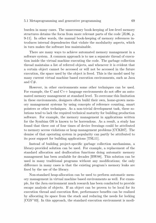
5.1 Metaprogramming and generative programming 69
burden in many cases. The unnecessary book-keeping of low-level memorystructures detains the focus from more relevant parts of the code [JL96, p.9-11]. In other words, the manual book-keeping of memory references in-troduces internal dependencies that violate the modularity aspects, whichin turn makes the software less maintainable.
There are many ways to achieve automated memory management in asoftware system. A common approach is to use a separate thread of execu-tion inside the virtual machine executing the code. The garbage collectionthread maintains a list of referred objects, and whenever it is evident thata certain object cannot be accessed or will not be accessed in the futureexecution, the space used by the object is freed. This is the model used bymany current virtual machine based execution environments, such as Javaand C#.
However, in other environments some other techniques can be used.For example, the C and C++ language environments do not offer an auto-mated memory management at standard level. To overcome this limitationin these environments, designers often build their own, home-grown mem-ory management systems by using concepts of reference counting, smartpointers or other techniques. As a non-trivial development task, these so-lutions tend to lack the required technical maturity for building productionsoftware. For example, the memory management in applications writtenfor the Symbian OS is known to be horrendous. As a result, a study hasfound that three out of four times of device freezings could be attributedto memory access violations or heap management problems [CCKI07]. Thedemise of that operating system in popularity can partly be attributed toits poor support for building applications [TSL11].
Instead of building project-specific garbage collection mechanisms, alibrary-provided solution can be used. For example, a replacement of thestandard allocation and deallocation functions doing automatic memorymanagement has been available for decades [BW88]. This solution can beused in many traditional programs without any modifications; the onlydifference in many cases is that the existing program’s memory leaks arefixed by the use of the library.
Non-standard heap-allocation can be used to perform automatic mem-ory management in virtual machine based environments as well. For exam-ple, for the Java environment much research has been conducted to provideescape analysis of objects. If an object can be proven to be local for itsexecution thread and execution flow, performance benefits can be realizedby allocating its space from the stack and reducing the needs for locking[CGS+03]. In this approach, the standard execution environment is modi-

70 5 Programs as models
fied to analyze the program flow, and to use a different allocation schemefor local objects.
The analysis of program’s code can also be done with external tools.For example, researchers have documented a case of a Scheme compilerwhich instruments the generated code with functionality to detect memoryleaks and to visualize the heap state [SB00].
As can be seen from this section, by just scratching the surface of theresearch done for a small sub-area of software engineering, we have iden-tified a number of approaches for implementing automated memory man-agement. The prevailing virtual machine based approach is complementedby a number of other techniques that use the source program as the modelfor configuring the way how memory is allocated and deallocated. Thesesolutions range from project-specific ones, which tend to be poorly general-izable, to generic, library-based solutions. As a bottom line, this discussionshows that it is actually not very uncommon for a software structure tocontain self-configuring components.
5.2 Program annotations
Annotating programs to provide hooks for different viewpoints is a popularway to embrace multiple meanings for software components. For example,the Scala program in Figure 5.1 is a tail recursive way for deciding whetherits input is a balanced list of parentheses.
@tailrec
def balance(chars: List[Char], level: Int): Boolean = {
if (level < 0) return false
if (chars.isEmpty) return level == 0
if (chars.head == ’)’)
return balance(chars.tail, level - 1)
else if (chars.head == ’(’)
return balance(chars.tail, level + 1)
else
return balance(chars.tail, level);
}
Figure 5.1: Compiler-enforced annotation to tail-recursiveness
In this example, the @tailrec annotation ensures that the program re-

5.2 Program annotations 71
ally is tail recursive - it tells the compiler to reject the code if it cannot becompiled to be executed in constant stack space.
Annotations are not limited for the compiler use only. Actually, oftenthe primary target of annotating programs is to guide the software’s frame-works and external tools about the meaning of the program. For example,when using an object-to-relational mapping (ORM) component to build apersistency layer, it is convenient to annotate class members with instruc-tions to the ORM tool on how to persist the member to the database. Thealternative is to use external configuration files to do the same.
Using an external configuration file decouples the actual definitions andcorresponding semantic guides. This alternative is a good idea when thereare many possible semantic interpretations in the given aspect, e.g. due toreconfiguration needs. However, when there is only one meaningful inter-pretation, it probably is a better idea to place the instructing guide as aprogram annotation.
Programming environments usually support a standardized way to useannotations with external tools. For example, the Java 5 platform pro-vides a possibility to annotate classes, class members, interfaces and otherlanguage constructs (but not all, e.g. local variables). An external tool[Sun04] provides hooks for external projects to plug into the processing ofannotations. The external tools can be used to modify the structure of theprocessed source code, based on the purpose of the plug-in in question.
Program annotations can be seen as a complementary way of providingprogram reification. In addition to the program’s dominant meaning, thealternate aspects can be guided via annotations. This way, program anno-tations can be used to decouple different aspects of the software’s structureinto meaningful modules. For example, consider the code fragment in Fig-ure 5.2 written in Scala:
@Entity
class PersistentBean = {
@BeanProperty
@Id
var id;
}
Figure 5.2: A class with multi-aspect annotations
The code introduces the class PersistentBean. The class is annotated tobe an @Entity, which tells the persistency framework that this class is to bepersisted. The class has a single attribute, id. There are two annotations

72 5 Programs as models
to this attribute: @BeanProperty and @Id. The former annotation tellsthe Scala compiler to automatically add getter and setter functions for theattribute. The latter annotation tells the persistency framework to treatthe attribute as the identity field of the objects belonging to this class.
Although the persistency framework advocates the use of transparentpersistency and the Scala language tries to avoid unnecessary introductionof get and set methods to all public attributes, the presence of persistencyand the tradition of Scala’s predecessor have ”sneaked” into this design.This kind of mixup, known as annotation hell [RV11] when unrestrictedlyused for larger number of annotated domains is not uncommon in largesoftware systems. Sometimes this kind of rectifying from the past is justconvenient, but sometimes we wish to have better means to control theforces that drive us to use annotations.
5.3 Program fragments as the source models
Although program annotations can be useful in many situations, there area number of cases where the use of annotations cannot be justified.
First of all, the annotations were originally developed to help in inject-ing aspect-specific processing instructions to program elements. As pro-moted in aspect-oriented programming [KLM+97], different aspects shouldbe modularized into decomposable units. The use of annotations injectsaspect-specific instrumentation to the target site, which breaks the princi-ple of modularity apart since the dependence target needs to be modifiedaccording to the needs to the dependent.
Another scenario where annotations are problematic is the case of mul-tiple aspects being attached to a single entity. In this case, each aspectwould inject its own semantic instructions to the instrumented site, whichcan prove to cause more problems than the injection mechanism can actu-ally solve.
Fortunately, there is an alternative: to build the software architectureto be aware of its own structure. By building self-organizing software com-ponents into the software architecture, there is no need to use artificialannotations to guide the different components into their semantic mean-ing.
As an example, we will build a simple command processor. Let usconsider the Java code in Figure 5.3. It first registers three objects forhandling different commands, and then repeatedly reads in a commandand dispatches following arguments to the given command.
For our discussion, the interesting property in this code lies in how the
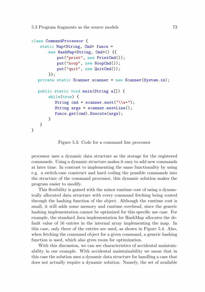
5.3 Program fragments as the source models 73
class CommandProcessor {
static Map<String, Cmd> funcs =
new HashMap<String, Cmd>() {{
put("print", new PrintCmd());
put("noop", new NoopCmd());
put("quit", new QuitCmd());
}};
private static Scanner scanner = new Scanner(System.in);
public static void main(String a[]) {
while(true) {
String cmd = scanner.next("\\w+");
String args = scanner.nextLine();
funcs.get(cmd).Execute(args);
}
}
}
Figure 5.3: Code for a command line processor
processor uses a dynamic data structure as the storage for the registeredcommands. Using a dynamic structure makes it easy to add new commandsat later time. In contrast to implementing the same functionality by usinge.g. a switch-case construct and hard coding the possible commands intothe structure of the command processor, this dynamic solution makes theprogram easier to modify.
This flexibility is gained with the minor runtime cost of using a dynam-ically allocated data structure with every command fetching being routedthrough the hashing function of the object. Although the runtime cost issmall, it still adds some memory and runtime overhead, since the generichashing implementation cannot be optimized for this specific use case. Forexample, the standard Java implementation for HashMap allocates the de-fault value of 16 entries in the internal array implementing the map. Inthis case, only three of the entries are used, as shown in Figure 5.4. Also,when fetching the command object for a given command, a generic hashingfunction is used, which also gives room for optimization.
With this discussion, we can see characteristics of accidental maintain-ability in our example. With accidental maintainability we mean that inthis case the solution uses a dynamic data structure for handling a case thatdoes not actually require a dynamic solution. Namely, the set of available

74 5 Programs as models
0 null1 null2 null3 null4 null5 null6 NoopOb7 null8 null9 null10 null11 null12 null13 QuitOb14 PrintOb15 null
Figure 5.4: HashMap default layout
commands is a property that is bound at design time, but implementedusing a structure that employs runtime binding. There are a number ofreasons for implementing the command processor in this way. The mapimplementation is available in the standard class library, its use is wellknown and understood among programmers and usually the induced over-head is negligible. Yet another reason can be the lack of viable alternatives.In cases where any overhead should be minimized, introducing this dynamicstructure purely due to comfort of the implementer would not be good useof scarce resources.
An alternative solution to this example is to create a specific imple-mentation of the map interface that is statically populated to contain allthe required elements. This would make it possible to use context-specificknowledge of the structure in implementing the command fetching system:instead of using a fully generic hashing table, more memory and runtimeefficient, specific hash table and hashing functions for the three commandscould be implemented.
The self-configurator component resolves this problem by introducinga configurator component to this structure. Figure 5.5 illustrates the con-figuration process. The self-configuring component reads the static listof commands and generates a specific hashing function, using e.g. gperf[Sch90] for this set of commands to be used. Now the runtime and memory

5.3 Program fragments as the source models 75
Figure 5.5: Self-configuring function for the command processor
overhead of generic hashing is avoided. The hash generation function isbound (i.e. executed) at the same time as all other parts are compiled.This way, the runtime overhead can be minimized. However, the design-time allocation of command names and associated functions still enjoys theflexibility of defining the command mapping as a well-understood, standardMap interface.
There is a degree of freedom in placing this generative part in the bind-ing time continuum. The hash generating function and associated hashmap generation can take place as part of the normal compilation process,or they can be delayed up until first use of the command processor object.As usual, earlier binding time gives opportunities for optimizing for thatspecial case, while dynamic binding gives more flexibility and possibilitiesto use contextual information to determine the behavior.
Applicability
There are many situations where self-configuring components can prove tobe useful. First of all, the pattern is applicable when you are using dy-namic structures to guard against changes that a future developer mightbe performing. In the example in the previous section, the dynamic map-ping structure defines a clear place for implementing additional commands.However, this flexibility is gained by introducing additional runtime cost.
Another scenario where you can find this pattern useful is when thereis a need to provide characteristics of one code site to parameterize anotherroutine. An example of this case can be e.g. a dependency between a setof different algorithms performing a computation upon data that is held inthe database. Each algorithm requests certain set of data, but you want toseparate the database fetching code from the algorithm’s processing code.In this case, you can introduce a self-configuring component to analyze eachspecific algorithm and to automatically produce optimized queries for eachof them without introducing a dependency between the query site and thealgorithm.

76 5 Programs as models
These types of applications have a dependency between the data thatis read from the database and the algorithm performing the calculations.Within the object-oriented style of programming, an additional object layeris built on top of a relational database, creating an additional problem ofobject/relational mismatch. An approach of building object-to-relationalmapping frameworks, such as Hibernate [BK06], proved to be popular as abridge between object-oriented application code and relational persistencestructures. In order to provide a fluent programming environment for theobject-oriented design, transparent persistence is one of the key phrases.The promise of transparent persistence means that objects can be pro-grammed as objects, without paying attention to the underlying relationaldatabase.
One of the tools for achieving transparent persistence is the usage of theProxy design pattern [GHJV95, pp. 207-217] to hide if an object’s internalstate is stored in the database, or whether it is already loaded to the mainmemory. However, in many cases this delayed fetching hides symptoms ofbad design: the program relies on the slow, runtime safety net implementedwith the proxy. A better design would be to explicitly define which objectshould be fetched. If the objects to be processed within a certain algorithmcan be known beforehand, the usage of the Proxy pattern can be classifiedas a design fault.
Optionally, the pattern can also expose details of the processed depen-dency via a dependency interface, which allows programmatic access tocharacteristics of this dependency. In the previous example, this kind ofdependency lies between the statically allocated list of commands and thecommand-line processing loop.
Implementation
In order to analyze a code site for configuring its dependents, there needs tobe a way to access the source data. When using compilation-time configura-tion, all the source code is available for analysis. For instantiation time andruntime configurations the analysis interface is defined by the execution en-vironment characteristics: some environments, known as homoiconic, suchas the LISP language, expose the full structure of the program for furtheranalysis; but many current environments do not. In the latter case, theimplementor needs to use his own reification strategy. Popular alternativesrange from byte-code analysis, such as the BCEL library [Dah99] in theJava environment, to standardized API access to program definition, asimplemented in .NET Expression trees, a data structure available in C#since its third version [Mic07].

5.3 Program fragments as the source models 77
Regardless of the used access method, the configurator component an-alyzes the dependent source. Based on this analysis, the dependent isconfigured to adhere to the form that is required by the source site. Inthe previous example, a possible configuration could be a generation of aminimal perfect hashing table for the different registered commands.
Often the required target configuration varies from one context to an-other. What is common in different variations is the built-in ability for thearchitecture to adapt to changes between architectural elements, which helpboth in maintenance and in gaining understanding of the overall system.
Drawbacks
Fred Brooks has asserted that ”There is no single development, in eithertechnology or management technique, which by itself promises even oneorder of magnitude [tenfold] improvement within a decade in productivity,in reliability, in simplicity” [Bro87]. This work does not claim to be such,either.
When building self-configuring software architectures, there are prob-lems in pre-emphasizing the future needs. The self-configurator ought tobe able to adjust its structure to meet the needs of future enhancements.Unfortunately, those people who have been gifted with clairvoyance abilitydo not end up being software developers. So, the main bulk of architecturalwork is done based on best guesses.
For example, the self-configurator component presented in Paper (V)can automatically reorganize database queries based on the algorithm ac-cessing the database as long as the component can recognize the analyzedalgorithm’s structure. If the implementation changes from the structureexpected by the self-configurator, then it obviously fails in its job.
Another problem is that writing self-aware code is often considered dif-ficult. In many cases, it seems to be outside the scope of project personnel.Although we have argued that in the past we have been able to implementself-organizing components in agile projects with strict time-boxing limits,it might be the case that this property is not generalizable over all softwareengineering organizations. In many places, even the term metaprogram-ming might be unknown concept. In these kinds of organizations, it can bebetter to start improvements by employing the more classical, well-maturedproductivity improving techniques.

78 5 Programs as models
Empirical results
The roots of self-configuring components are based on industrial softwareengineering setting: a software product line developed in telecom sectorneeded improved configurability. Papers (III), (IV) and (V) discuss differ-ent aspects of building these components. As this work was done in onecompany, in one development team using one set of technologies, one canargue that the success of the techniques relied upon the skilled engineerswho were doing extraordinary work in that one particular environment.To prove wider applicability, the techniques should be able to demonstrateusefulness in other contexts as well.
Controlled experiments are a way to gain insights to this kinds of phe-nomena. Widely used in many fields of science, they can be employed incomputer science as well. One of the most straightforward ways of per-forming controlled experiments is the A/B testing. The idea is to dividethe test population to two groups: the first group acts as the control group:they experience a traditional, or baseline treatment. The second group isexposed to an alternative, slightly varied treatment. Finally, changes inoutcomes is observed.
In order to understand how well the self-configuring components workin new contexts, we performed a randomized, controlled experiment as doc-umented in Paper (VI). Although the number of test subjects was low, theinitial results were impressive: test subjects using the self-configuring com-ponents outperformed the traditional object-to-relational mapping users bya factor of three in number of functionally correct submissions. As the re-sult is statistically significant, we have a reason to believe the approach tobe useful in other contexts as well.
5.4 Related work
The theme of reducing maintenance effort via metaprogramming supportcan be seen in many existing software projects. In the context of self-configuring software components, the special interest lies in the area ofintrospective metaprogramming that allows the software to reconfigure itscomponents as maintenance changes are being made.
Self-configuring components by reflection
Using reflection to build self-configuring components has long been knownas a way to build resilient software. For example, the standard class libraryin Java since version 1.3 has included the concept of dynamic proxy classes

5.4 Related work 79
for interfaces. Other people have also proposed extending this functionalityto classes as well [Eug03].
Similar techniques can be applied to arbitrary code entities. For exam-ple, in section 4.5 we discussed framelets as a bottom-up way to buildingframeworks. Using reflectional access to the interface of a framelet has beenshown to be a viable way of automating component gluing [PAS98].
Automatic compiler generation
Generative programming has long been used in constructing the front-endof a compiler: lex [LS75], yacc [Joh78], and their descendents and look-alikes are routinely used in building the front-end. However, this solvesonly a fraction of the problem; some estimate the scanning and parsingphases to account for 15% of the whole task [Wai93].
Tim Barners-Lee is quoted of saying: ”Any good software engineer willtell you that a compiler and an interpreter are interchangeable”. The ideabehind this quote is that since the interpreter executes code in the inter-preted language, it necessarily has the required knowledge for producing theequivalent lower level code. Also the other way applies: the compilationroutines for a given language can also be harnessed to build an equivalentinterpreter.
The top-down approach to increasing the amount of automatically gen-erated parts of a compiler is to introduce stronger formalisms for describingthe functionality of the compiler. Larger parts of the compiler can be gener-ated by using e.g. attribute grammars to describe the compiler’s semantics[KRS82] .
This interchanging process can also be seen as a self-configuration com-ponent. This has been applied e.g. to build compilers for embeddeddomain-specific languages [EFM00] and to produce portable execution en-vironments for legacy binaries [YGF08].
For example, consider the code in Figure 5.6 as an interpreter of alanguage. The interpreter is given a list of function pointers to the instruc-tions of the executed program. After each function pointer invocation, theinstruction pointer is incremented to point to the next memory locationwhere the next instruction resides. When the instruction pointer becomesnull, execution terminates.
This is a compact way to implement an interpreter. However, the realproblem resides in implementing the actual instructions. The usual wayfor implementing semantics of the language, as employed e.g. in Paper (II)is to hand-write a code generator to emit the lower-level instructions. Theexample used in the Paper shows an implementation for generating code
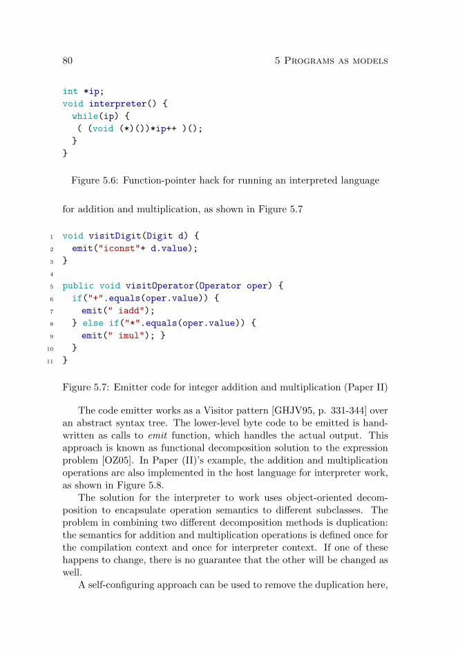
80 5 Programs as models
int *ip;
void interpreter() {
while(ip) {
( (void (*)())*ip++ )();
}
}
Figure 5.6: Function-pointer hack for running an interpreted language
for addition and multiplication, as shown in Figure 5.7
1 void visitDigit(Digit d) {
2 emit("iconst"+ d.value);
3 }
4
5 public void visitOperator(Operator oper) {
6 if("+".equals(oper.value)) {
7 emit(" iadd");
8 } else if("*".equals(oper.value)) {
9 emit(" imul"); }
10 }
11 }
Figure 5.7: Emitter code for integer addition and multiplication (Paper II)
The code emitter works as a Visitor pattern [GHJV95, p. 331-344] overan abstract syntax tree. The lower-level byte code to be emitted is hand-written as calls to emit function, which handles the actual output. Thisapproach is known as functional decomposition solution to the expressionproblem [OZ05]. In Paper (II)’s example, the addition and multiplicationoperations are also implemented in the host language for interpreter work,as shown in Figure 5.8.
The solution for the interpreter to work uses object-oriented decom-position to encapsulate operation semantics to different subclasses. Theproblem in combining two different decomposition methods is duplication:the semantics for addition and multiplication operations is defined once forthe compilation context and once for interpreter context. If one of thesehappens to change, there is no guarantee that the other will be changed aswell.
A self-configuring approach can be used to remove the duplication here,

5.4 Related work 81
abstract eval();
expression lhs, rhs;
operator() {
if (token == ’+’) { eval <- plus.eval; }
else if (token == ’*’) { eval <- times.eval; }
}
// methods plus.eval and times.eval
plus.eval() {
return lhs.eval() + rhs.eval();
}
times.eval() {
return lhs.eval() * rhs.eval();
}
Figure 5.8: Interpreter code for integer addition and multiplication (PaperII)
as is shown in [YGF08]. When we examine the code produced by thestandard compiler for the method plus.eval, as shown in Figure 5.9, wesee clear correspondence to the Visitor method in Figure 5.7. The iaddinstruction on the line 7 in the Java listing corresponds to the byte codeinstruction at index #2 in the reverse engineered version of the class.
$ javap -c Plus
Compiled from "Plus.java"
public class Plus extends java.lang.Object{
[..]
public int eval(int, int);
Code:
0: iload_1
1: iload_2
2: iadd
3: ireturn
}
Figure 5.9: Compiled code for method plus.eval
The instructions at indices 0 and 1 in the compiled code load their argu-ments. The instruction 2 is correspondent to the emit-method call in Figure

82 5 Programs as models
5.7. Finally, the instruction 3 returns the result back to the caller. To builda self-configured version of the interpreter/compiler, the self-configuratorcan build a compiler from the interpreter by analyzing each opcode defini-tion of the interpreter and by emitting each opcode’s corresponding codeas the code generation step. This is a way to treat software’s methods asthe source model of a model-driven compiler engineering.
Software renewal via code transformations
In the heart of software maintenance justification lies the fact that rewritingsoftware is a dangerous business decision. Existing software investmentencodes countless special cases and their handling rules in its correspondingenvironment. Evolution can happen via modular changes, but full systemchanges are rare and inherently dangerous. This is why the text in flighttickets is still written in upper case letters.
Sometimes, in cases of low competition, companies might be able torenew their main operating software. An example of a documented sur-vival case for a company transiting from a mainframe-based software to anewer Windows-based system can be found from Finnish Agricultural DataProcessing Centre [NJGG10]. In this case, the transition from the 30-yearold mainframe-based legacy information processing environment to mod-ernized relational database system was made possible only by low pressurefrom competition.
In environments of higher competition, software businesses very seldomcan enjoy the liberty of rewriting their old codebase. For example, the mainreason for Netscape to lose the so-called ”browser war” and ultimately itsindependence is attributed to the business decision to rewrite their oldcode [Spo04, p. 183-187]. Based on this example, companies are usuallyreluctant to make business decisions to a full-rewrite, and they probablyare wise in that.
Figure 5.10 draws a picture of what customers experience when a com-pany decides to rewrite its software from scratch. The company can shipthe old version of the software while work is undergoing to produce the newversion (old version functionality). Customers experience no new featuresor other development while development of the new version is in progress.It is going to be a long time before the recoding achieves the level of func-tionality provided by the old version (recode progress). It should be notedthat unlike people often assume, the total effort in redoing the softwareprobably is not smaller than when doing the previous version [Spo04, p.186].
The next option is not to throw the old codebase away, but place it in

5.4 Related work 83
Features
Time!
Recode progress!
Old version functionality!
Figure 5.10: Rewriting the software from scratch: time-to-market is long[KB12]
maintenance mode until the new version has been completed. The split-versions strategy can work for companies with large resources to throw ata given renewal project. Depending on competition situation, the time-to-market can be shortened by selecting only the most important features ofthe software to be implemented first. This strategy is what Apple usedwhen transitioning the QuickTime software from 32-bit version 7 to the64-bit version QuickTime X. The initial release of version X was severelylimited: it allowed only the very basic video playback operations, and theolder version was still offered for any serious work [Sir09].
This strategy is shown in Figure 5.11. Customers experience a slowed-down development of the old codebase, and the new development is sloweddown due to the need to support the old codebase. It can be questionedwhether the rewrite will ever get ready in this case.
Unfortunately, not all companies have similar resources and strong gripof their customers, and they also need to renew their software offeringwithout such major disruptions that QuickTime users experienced. Codetransformations can be used to help in code renewal in a similar way toself-configuring components.
An example case of using code transformations for code renewal hasbeen presented in industrial context [KB12]. In this case, the companyhas built a ship structural modeling software NAPA, based on Fortran andself-developed BASIC-flavour, with the total line count ranging in 2 millionsource lines of code in Fortran and about the same in the in-house BASIC.The company developers have estimated the existing codebase to accountfor 150 man years of work.

84 5 Programs as models
Features!
Time!
Recode progress!
Old version functionality!
Figure 5.11: Recode on the side: split focus hinders all development [KB12]
Since not many computer science curricula include Fortran as a ma-jor educational building block and the used BASIC language is company-specific, the company is experiencing a major struggle in driving softwaredevelopment. The business environment gives a continuos pressure to keepadding features to the product, mandates maintenance development for ex-isting customers and requires custom projects of special features for keycustomers. Competition ensures that ”freezing” of feature development isnot an option for a major technology overhaul [KB12].
Using code transformations similar to self-configuring components canbe used to build a roadmap of technological transition. In the NAPAcase, the work consisted of a BASIC-parser written in ANTLR [PQ94]and few thousand lines of pattern matching code, written in Mathematica[Wol03]. In this kind of renewal the idea is to iteratively find generic rulesfor translating from the legacy system to the modern technology [Bro10].Similar approaches have been used previously in legacy system renovations,for example in renewal of COBOL-based banking systems [vD99].
In principle, the renewal progresses as shown in Figure 5.12. The cover-age of translation rules can be supposed to experience a law of diminishingreturns: initially few basic rules can handle large amounts of legacy sourcecode. The leftovers are harder and harder to handle using systematic pat-tern matching rules. When the gap between legacy functionality and thecode covered with transformations is deemed small enough, the develop-ment team makes a ”jump of faith” to generate a modernized version ofthe legacy code, and all further development stays in that version.
In this version, customers see development continuing with normal, ora bit slower pace in the legacy codebase. With iterative enhancements to

5.4 Related work 85
Features!
Time!
Normal development!
Transformed features!
Transformation rules!
Figure 5.12: Code transformations are iteratively developed [KB12]
the transformation rules and legacy codebase refactoring, the amount ofcorrectly transformed code in the legacy platform grows. After the trans-formation rules is deemed good enough, all development is transitioned tothe renewed platform, which consists of automatically generated code fromthe legacy codebase.
However, it should be noted that the development speed charts in Fig-ures 5.10, 5.11, and 5.12 are hypothetical, generated by using a pseudo-random number generator. It should be investigated whether this kind ofapproach works in practice. Initial reports suggest that in the examplecase company the transformation has been successful [Bro13], but morerigorous studies should be performed to gain better understanding of codetransformation mechanics in practice.
Software productivity via code transformations
Code transformations can be useful not only in modernizing legacy code,but in building multi-platform software as well. For example, when produc-ing software to be run on both Android and iOS platforms, several teamsat Google use a Java-to-ObjC translator tool, J2ObjC [Bal13].
The tool has implemented a semantic translation from business-levelJava code to corresponding Objective C constructs. This way, the businesscode can be written only once in Java for the Android platform, and thentranslated to iOS. By automating this translation, the development teamsdo not encounter synchronization problems between two code bases, butinstead can be sure that the business functionality is based on the samesource. Figure 5.13 shows a schema of this tool usage.

86 5 Programs as models
Business logic (Java)
Android UI(Java)
Business Logic (ObjC)
iOS UI(ObjC)
J2ObjC
Android stack iOS stack
Figure 5.13: Semantic translation from Java to ObjC used to synchronizebusiness logic to two platforms
The tool tackles the problems of full code translation by limiting itselfpurely to the business domain, meaning that the user interface level needsto be written separately to both of the platforms. This is understandablesince the user interface principles are different in the platforms.
Contrary to the one-time translation approach used in renewing tech-nology as presented in the previous section, the target of J2ObjC is toprovide a continuous integration between the two platforms. This is a wayto provide programming productivity in the case of multi-platform devel-opment. Projects can complete faster because they do not need to dupli-cate the business logic to both platforms. When a new, previously onlyAndroid-based project wants to join in, the translator tool usually needsto adjust to handle the new special cases introduced by the joining project.This way, over time the translator tool evolves to handle larger and morecomplex cases. Projects can meanwhile enjoy improved productivity andconcentrate to polish the user experience on the different platforms.
The difference between the examples in this and the previous sectionresemble the difference between translationalist and elaborationalist ap-proaches to model-driven engineering discussed in Section 3.2. The ap-proach to build an initial code transformation suite to lessen the gap whenjumping from the legacy codebase to a modern platform resembles the elab-orationistic approach. The code transformation suite is being incompleteand can be compensated by manual coding. On the other hand, introduc-ing the code translation tool as a part of everyday build cycle resemblesthe translationalistic approach: the target is to support all possible sourcecode constructs.

Chapter 6
Conclusions
Improving programming productivity is the main theme of this thesis. Wehave focused on two related approaches: first by using bottom-up modelingto build project-specific modeling environments, and second by using thesoftware’s own source components as source models in model translationsto build improved resilience. Resilience in software means that changescan be made locally, without dependency-based rippling effects breakingits overall structure. In this chapter, we discuss the implications of theseapproaches.
This chapter proceeds as follows. Section 6.1 relates the material inthis introductory part to the papers that follow the introductory part andreview contributions of the thesis. Section 6.2 reviews the limitations ofthe thesis. Section 6.3 outlines possible future research.
6.1 Contributions of the thesis
In Papers (I) and (II) we deploy the traditional software engineering tech-niques to build an optimizing compiler and a language generator. In thesepapers, we show incremental evolution to existing approaches.
In Paper (III) we build a project-specific modeling language with abinding to the existing body of computational knowledge. The modelinglanguage is exposed as a runtime entity to the project structure, allowingcomputational access in other parts of the software. This leads to theidea of using the software’s own structures as computational elements aswell. This is called the self-configurator component, as the self-configuratorreads in the software’s definition and uses its characteristics to configuresome other part of the software. In Papers (IV) and (V) we have applied theself-configurator component in two different contexts. Paper (VI) conducts
87

88 6 Conclusions
an empirical experiment in a randomized, controlled environment with theresult of finding the self-configurator variant to be more effective in buildingworking code.
In Paper (IV) we express the case of component-based software engi-neering that is widely employed in the area of user interface composition.User interface widgets can be developed as stand-alone components, andthe interface of a new application can be built by composing from a paletteof these ready-made components. Pioneered in Visual Basic, the approachhas been adapted to numerous application areas.
One of the drawbacks in component-based user interface composing isthe need for duplicated binding expressions when programmatically defin-ing multiple properties of user interface components. For example, whendefining whether a user interface component is active or not, a corre-sponding tooltip should be placed. Without sufficient support for cross-referencing to other binding expressions, providing this kind of conceptualcoherence in the user interface requires cloning of the behavior definingexpressions.
We have built a prototype for analyzing these binding expressions inthe standard Java environment for building web interfaces. By exposingthe structure of the binding expressions to backend code, we were able toreduce the amount of cloned binding expressions by a factor of 3 in a demoapplication presented in Paper (IV).
In Paper (V) we consider typical database applications: they read datafrom a database to the main memory, perform an algorithm on the data,and then write the result back into the database. In the paper we havedocumented the usage of self-configured database queries as a tool to im-prove the runtime properties of this case. In this design, a code analyzerreads in the byte-code of a given algorithm and deducts the required queriesfor prefetching the needed data from the database. This design improvesmaintainability: should the algorithm change for some reason, the fetchingcode is automatically updated to reflect the change. Another benefit is thaton the architectural level, the number of database-accessing components isreduced, since this one component can configure itself for multiple cases.
In Paper (VI) we report a controlled, randomized experiment on stu-dents to determine whether the self-configurator component is useful forperforming maintenance tasks. We built two versions of a simple databaseapplication. The first version uses the self-configuring component presentedin Paper (V), and the second version uses the transparent persistency. Al-though the two versions differ only in a few lines of code, based on theresults the few lines seem to be crucial for performing maintenance tasks.

6.2 Limitations of the thesis 89
The result suggests that unlimited separation of concerns might be harm-ful for rapid maintenance tasks: the members in a control group, usingthe self-configuring query component, performed statistically significantlybetter in the experiment in terms of correct submissions.
6.2 Limitations of the thesis
In the included papers, we have contributed to software engineering tech-niques in a number of areas, including mobile software development, object-oriented grammar implementation, mobile network development, databasedevelopment, and user interface development. The usefulness of one of thecontributions, the database component, was empirically validated.
It can be seen as a limitation of the thesis that not all of the con-tributions have been rigorously validated, but their applicability is basedon observations of industrial practice rather than randomized, controlledexperiments. Unfortunately, performing controlled trials is expensive andtime-consuming. Thus, more thorough empirical evaluation was not possi-ble in the scope of this work.
The empirical validation presented in Paper (VI) was performed byusing students of the conducting university as test subjects. The test groupcan be argued to be small, since only 16 students attended the test. Formore reliable results, larger populations should have been used.
6.3 Future directions of research
The main message of this thesis can be summarized as follows: in orderto build maintainable software, an increasing number of software entitiesmust be addressable by software.
This means that existing abstractions need to be made more accessi-ble through introspective and reflective interfaces. For new abstractions,designers should think ahead how the new abstractions would be program-matically accessed - can the entity in question be a so-called first-classcitizen in the system.
This is an everlasting quest, since both academia and the industry seemto be endlessly creative in creating new structures, frameworks and systemsto be used. Since the number of possible combinations is unlimited, we haveno fear that maintenance work of these would come to an end.
For the short term, the work could expand to cover new application ar-eas for self-configurative components. It would be best to start in domainsthat involve a high frequency of application and are currently manually

90 6 Conclusions
done. The work presented in this thesis concentrated on a traditional soft-ware engineering setting, where teams of programmers, designers and archi-tects work on a software product, using general-purpose languages. Usingself-configurative components could be employed in this area to speed up de-velopment work and to allow clever programmers to concentrate on harderproblems, instead of wasting their time in doing bulk, automatable work.In order to validate the usefulness of these efforts, longitudinal studies onproductivity would be needed.
We could also broaden the viewpoint from pure software engineeringto all software creation. Most of software creation lies outside of softwareengineering scope: for every professional programmer, there are at least tenbusiness majors who are doing scripting in their spreadsheet programs. Iferrors in enterprise software are bad, the errors in spreadsheet-based busi-ness decisions can be disastrous. For example, famous economists havestudied the relation between a nation’s gross domestic product and thedebt. Their main result is that median growth rates for countries withpublic debt over 90 percent of GDB are roughly one percent lower thanotherwise and average growth rates are several percent lower [RR10]. Thisall makes sense, except that the conclusion is based on errors in the re-searchers’ spreadsheet: they forgot to include a number of countries thathappened to have high public debt and better GDB growth rates [HAP13].
These kinds of problems could be mitigated with self-configuring extract-transform-load (ETL) components. When extracting data from a datasource, the current transformations usually evaluate the possible sourcestatements. Often the target system could as well evaluate the expressions,but successfully carrying the semantic transformations from the source sys-tem to the target system can be cumbersome. By using self-configuringprograms, the transformations could be automatically carried to the targetsystem, e.g. to be used in a spreadsheet. This kind of improvement wouldbe a good target, since ETL programs are widely used in the industry,and are known to be tedious to build and cumbersome to modify. Thus, aself-configuring Excel-sheet is the next thing to do.
In the long term, building improved resilience as a routine work of soft-ware engineering is needed. More complex software is being produced withthe need to address more specific customer needs. Software product lines,mass customized software and software factories make the space of possi-ble software configurations much larger than programmers, designers andarchitects have used to handle. Software engineers are so busy with pro-viding value that there is no room for any activities that will be wasted:in the future, less time will be spent on formal reviews, using the UML or

6.3 Future directions of research 91
using sophisticated metrics to understand productivity. Customers wanttheir software and they want it now. Cheaply. The key to achieving thisis to building in quality assurance: continuous, automated testing is imple-mented to reduce waste.
The logical next step is to change the software’s configuration frommanually handled configuration management to automatically managed.Self-configuring software components are a tool for implementing automat-ically configuring, change-resilient software architectures within the tightlybudgeted projects that are today’s norm in the software industry.
When self-configuration as a tool to provide self-organization in softwarearchitectures is common knowledge, the next steps take us higher: how doself-configuring components interact and how should they interact. Canthere be self-configuring components that configure other self-configuringcomponents? Will there be a need for higher-order self-configuration?Questions like this are to be answered in the future.

92 6 Conclusions

References
[ABK10] Pekka Abrahamsson, Muhammad Ali Babar, and PhilippeKruchten. Agility and architecture: Can they coexist? IEEESoftware, 27(2):16–22, 2010.
[ADGR05] Emmanuelle Anceaume, Xavier Defago, Maria Gradinariu,and Matthieu Roy. Towards a theory of self-organization.In James H. Anderson, Giuseppe Prencipe, and Roger Wat-tenhofer, editors, 9th International Conference on Principlesof Distributed Systems OPODIS 2005, Revised Selected Pa-pers, volume 3974 of Lecture Notes in Computer Science,pages 191–205. Springer, 2005.
[AK04] Pekka Abrahamsson and Juha Koskela. Extreme program-ming: A survey of empirical data from a controlled casestudy. In Proceedings of the 2004 International Symposiumon Empirical Software Engineering, ISESE ’04, pages 73–82,Washington, DC, USA, 2004. IEEE Computer Society.
[AK09] Sven Apel and Christian Kastner. An overview of feature-oriented software development. Journal of Object Technology(JOT), 8(5):49–84, July/August 2009. Refereed Column.
[Alb79] Aj Albrecht. Measuring application development productiv-ity. In I. B. M. Press, editor, IBM Application DevelopmentSymposium, pages 83–92, October 1979.
[AM04] Michalis Anastasopoulos and Dirk Muthig. An evaluation ofaspect-oriented programming as a product line implementa-tion technology. In Proceedings of the International Confer-ence on Software Reuse (ICSR), pages 141–156, 2004.
[Amb04a] Scott Ambler. Agile model driven development is goodenough. IEE Software, 21(5):71–73, 2004.
93

94 References
[Amb04b] Scott Ambler. The Object Primer: Agile Model-Driven De-velopment with UML 2.0. Cambridge University Press, 3rdedition, 2004.
[AN93] Alain Abran and Hong Nguyenkim. Measurement of themaintenance process from a demand-based perspective.Journal of Software Maintenance: Research and Practice,5(2):63–90, 1993.
[AR06] Nitin Agarwal and Urvashi Rathod. Defining ’success’ forsoftware projects: An exploratory revelation. InternationalJournal of Project Management, 24(4):358 – 370, 2006.
[AWSR03] Pekka Abrahamsson, Juhani Warsta, Mikko T. Siponen, andJussi Ronkainen. New directions on agile methods: a com-parative analysis. In Proceedings of the 25th InternationalConference on Software Engineering, ICSE ’03, pages 244–254, Washington, DC, USA, 2003. IEEE Computer Society.
[BA04] Kent Beck and Cynthia Andres. Extreme Programming Ex-plained: Embrace Change (2nd Edition). Addison-WesleyProfessional, 2004.
[Bab09] Muhammad Ali Babar. An exploratory study of architec-tural practices and challenges in using agile software devel-opment approaches. In WICSA/ECSA, pages 81–90. IEEE,2009.
[Bal13] Tom Ball. Personal communication, 2013.
[Bat05] Don Batory. Feature models, grammars, and propositionalformulas. In Proceedings of the 9th international conferenceon Software Product Lines, SPLC’05, pages 7–20, Berlin,Heidelberg, 2005. Springer-Verlag.
[BCC+10] Hugo Bruneliere, Jordi Cabot, Caue Clasen, FredericJouault, and Jean Bezivin. Towards model driven tool inter-operability: Bridging Eclipse and Microsoft modeling tools.In Thomas Kuhne, Bran Selic, Marie-Pierre Gervais, andFrancois Terrier, editors, ECMFA, volume 6138 of LectureNotes in Computer Science, pages 32–47. Springer, 2010.
[BCT05] Alan Brown, Jim Conallen, and Dave Tropeano. Practi-cal insights into model-driven architecture: Lessons from
References 95
the design and use of an MDA toolkit. In Sami Beydeda,Matthias Book, and Volker Gruhn, editors, Model-DrivenSoftware Development, pages 403–431. Springer Berlin Hei-delberg, 2005.
[BG09] Andrew Berns and Sukumar Ghosh. Dissecting self-* prop-erties. In 2012 IEEE Sixth International Conference onSelf-Adaptive and Self-Organizing Systems, pages 10–19, LosAlamitos, CA, USA, 2009. IEEE Computer Society.
[BH12] Andrew Binstock and Peter Hill. The comparative pro-ductivity of programming languages. Dr. Dobb’s Jour-nal, 2012. http://www.drdobbs.com/jvm/the-comparative-productivity-of-programm/240005881.
[BJV04] Jean Bezivin, Frederic Jouault, and Patrick Valduriez. Onthe need for megamodels. In Proceedings of the OOPSLA/G-PCE: Best Practices for Model-Driven Software Develop-ment workshop, 19th Annual ACM Conference on Object-Oriented Programming, Systems, Languages, and Applica-tions, 2004.
[BK06] Christian Bauer and Gavin King. Java Persistence with Hi-bernate. Manning Publications Co., Greenwich, CT, USA,2006.
[BL76] Laszlo Belady. and Meir Lehman. A model of large pro-gram development. IBM Systems Journal, 15(3):225–252,September 1976.
[BLD11] Mario Bernardi, Giuseppe Di Lucca, and Damiano Distante.A model-driven approach for the fast prototyping of webapplications. In Proceedings of 13th IEEE InternationalSymposium on Web Systems Evolution (WSE), pages 65–74,Sepember 2011.
[BM04] Paul V. Biron and Ashok Malhotra, editors. XML SchemaPart 2: Datatypes. W3C Recommendation. W3C, secondedition, October 2004.
[Boe87] Barry W. Boehm. Improving software productivity. Com-puter (IEEE), 20(9):43–57, September 1987.

96 References
[Boe88] Barry W. Boehm. A spiral model of software developmentand enhancement. Computer, 21(5):61–72, May 1988.
[Bro87] Frederick Brooks. No silver bullet: Essence and accidents ofsoftware engineering. Computer, 20(4):10–19, April 1987.
[Bro95] Frederick Brooks. The mythical man-month (anniversaryed.). Addison-Wesley Longman Publishing Co., Inc., Boston,MA, USA, 1995.
[Bro10] Robert Brotherus. Transforming a legacy GUI to WPF andIronRuby. Chapter 10 in Porto Carrero / IronRuby In Ac-tion (unpublished), 2010.
[Bro13] Robert Brotherus. Personal communication, 2013.
[BS13] Hamid Bagheri and Kevin J. Sullivan. Bottom-up model-driven development. In David Notkin, Betty H. C. Cheng,and Klaus Pohl, editors, Proceedings of 35th InternationalConference on Software Engineering, ICSE’13, pages 1221–1224. IEEE / ACM, 2013.
[BSST93] Don Batory, Vivek Singhal, Marty Sirkin, and Jeff Thomas.Scalable software libraries. SIGSOFT Software EngineeringNotes, 18(5):191–199, December 1993.
[BW88] Hans-Jurgen Bohm and Mark Weiser. Garbage collection inan uncooperative environment. Software, Practice & Expe-rience, 18(9):807–820, 1988.
[Cas94] Eduardo Casais. An experiment in framework develop-ment - issues and results. In Architectures and Processesfor Systematic Software Construction. FZI-Publication,Forschungszentrum Informatik, 1994.
[CCC+11] Antonio Contieri, Guilherme Correia, Thelma Colanzi, Itanade Souza Gimenes, Edson Oliveira, Sandra Ferrari, PauloMasiero, and Alessandro Garcia. Extending UML compo-nents to develop software product-line architectures: Lessonslearned. In Ivica Crnkovic, Volker Gruhn, and MatthiasBook, editors, Proceedings of 5th European Conference onSoftware Architecture, volume 6903 of Lecture Notes in Com-puter Science, pages 130–138. Springer, 2011.

References 97
[CCKI07] Marcello Cinque, Domenico Cotroneo, Zbigniew Kalbarczyk,and Ravishankar K. Iyer. How do mobile phones fail? Afailure data analysis of Symbian OS smart phones. In 37thAnnual IEEE/IFIP International Conference on DependableSystems and Networks, DSN ’07, pages 585–594, June 2007.
[CdPL02] Luiz Marcio Cysneiros and Julio Cesar Sampaiodo Prado Leite. Non-functional requirements: Fromelicitation to modelling languages. In Proceedings of the24th International Conference on Software Engineering,ICSE ’02, pages 699–700, New York, NY, USA, 2002. ACM.
[CE00] Krzysztof Czarnecki and Ulrich W. Eisenecker. Genera-tive Programming: Methods, Tools, and Applications. ACMPress/Addison-Wesley Publishing Co., New York, NY, USA,2000.
[CGS+03] Jong-Deok Choi, Manish Gupta, Mauricio J. Serrano, Vu-granam C. Sreedhar, and Samuel P. Midkiff. Stack alloca-tion and synchronization optimizations for Java using escapeanalysis. ACM Transactions on Programming Languagesand Systems, 25(6):876–910, November 2003.
[Cha94] The CHAOS report. Technical report, Standish Group In-ternational, 1994.
[Cha03] The CHAOS report. Technical report, Standish Group In-ternational, 2003.
[Cha09] The CHAOS report. Technical report, Standish Group In-ternational, 2009.
[CJ01] Matthias Clauß and Intershop Jena. Modeling variabilitywith UML. In GCSE 2001 Young Researchers Workshop,2001.
[Coo12] William Cook. UML is the worst thing to ever happen toMDD. Fortunately many people now realize this ... shouldI list the reasons? UML was created to model OO designs.It effect you are modeling the code of a system, not thesystem’s behavior. UML is at wrong level. 2) the idea that7 (or 13) diagram formats in UML can cover everything iscrazy. What about GUIs, web wireframes, authorization, etc.??? 3) UML has encouraged the idea that models must be

98 References
graphical. Ridiculous! Text and graphic models are bothuseful and often interchangeable. 4) UML is at once too largeand complex and at the same time very limiited. stereotypeand profiles are not effective for usable extensions. 5) thePIM/PSM distinction is misguided. The purpose of high-level models is not platform independence. It is about ”what”versus ”how”. Tweet, Jun 2012.
[CROB05] Timothy J. Coelli, D. S. Prasada Rao, Christopher J.O’Donnell, and George E. Battese. An introduction to ef-ficiency and productivity analysis. Springer, New York, NY,second edition, 2005.
[DA10] Jean-Marc Desharnais and Alain April. Software mainte-nance productivity and maturity. In Proceedings of the11th International Conference on Product Focused Software,PROFES ’10, pages 121–125, New York, NY, USA, 2010.ACM.
[Dah99] Markus Dahm. Byte code engineering. In Clemens H. Cap,editor, Java-Informations-Tage 1999 JIT’99, Informatik ak-tuell, pages 267–277. Springer Berlin Heidelberg, 1999.
[DBT11] Frank Dordowsky, Richard Bridges, and Holger Tschope.Implementing a software product line for a complex avionicssystem. In Proceedings of the 15th International SoftwareProduct Line Conference, SPLC ’11, pages 241–250, Wash-ington, DC, USA, 2011. IEEE Computer Society.
[DE05] Bergfinnur Durhuus and Soren Eilers.On the entropy of LEGO, April 2005.http://arxiv.org/abs/math.CO/0504039.
[DeM86] Tom DeMarco. Controlling Software Projects: Management,Measurement, and Estimates. Prentice Hall PTR, UpperSaddle River, NJ, USA, 1986.
[DeM09] Tom DeMarco. Software engineering: An idea whose timehas come and gone? IEEE Software, 26(4):96, 95, 2009.
[Den03] Peter J. Denning. Great principles of computing. Commu-nications of the ACM, 46(11):15–20, November 2003.

References 99
[DP06] Brian Dobing and Jeffrey Parsons. How UML is used. Com-munications of the ACM, 49(5):109–113, May 2006.
[DT09] Shlomi Dolev and Nir Tzachar. Empire of colonies: Self-stabilizing and self-organizing distributed algorithm. Theo-rerical Computer Science, 410(6-7):514–532, 2009.
[EFM00] Conal Elliott, Sigbjorn Finne, and Oege de Moor. Compilingembedded languages. In Proceedings of the InternationalWorkshop on Semantics, Applications, and Implementationof Program Generation, SAIG ’00, pages 9–27, London, UK,UK, 2000. Springer-Verlag.
[EH07] Torbjorn Ekman and Gorel Hedin. The JastAdd system -modular extensible compiler construction. Science of Com-puter Programming, 69(1-3):14–26, 2007.
[EHS10] Basem S. El-Haik and Adnan Shaout. Software Design forSix Sigma: A Roadmap for Excellence. Wiley Publishing,1st edition, 2010.
[Eug03] Patrick Th. Eugster. Dynamic proxies for classes: Towardstype-safe and decoupled remote object interaction. Tech-nical Report IC 200317, Ecole Polytechnique Federale deLausanne, 2003.
[Eva03] Eric Evans. Domain-Driven Design: Tacking Complexity Inthe Heart of Software. Addison-Wesley Longman PublishingCo., Inc., Boston, MA, USA, 2003.
[EvdB10] Luc Engelen and Mark van den Brand. Integrating tex-tual and graphical modelling languages. Electronic Notesin Theoretical Computer Science (ENTCS), 253(7):105–120,September 2010.
[Fea04] Michael Feathers. Working Effectively with Legacy Code.Prentice Hall PTR, Upper Saddle River, NJ, USA, 2004.
[FGDTS06] Robert B. France, Sudipto Ghosh, Trung Dinh-Trong, andArnor Solberg. Model-driven development using UML 2.0:promises and pitfalls. Computer, 39(2):59–66, February2006.

100 References
[FKA+12] Janet Feigenspan, Christian Kastner, Sven Apel, JorgLiebig, Michael Schulze, Raimund Dachselt, Maria Pa-pendieck, Thomas Leich, and Gunter Saake. Do backgroundcolors improve program comprehension in the #ifdef hell?Empirical Software Engineering, pages 1–47, May 2012.
[Fow10] Martin Fowler. Domain-Specific Languages. Addison-WesleyProfessional, first edition, October 2010.
[FP98] Norman E. Fenton and Shari Lawrence Pfleeger. SoftwareMetrics: A Rigorous and Practical Approach. PWS Publish-ing Co., Boston, MA, USA, 2nd edition, 1998.
[GFd98] Martin Griss, John Favaro, and Massimo d’Alessandro. In-tegrating feature modeling with the RSEB. In Proceedings ofthe 5th International Conference on Software Reuse, ICSR’98, pages 76–85, Washington, DC, USA, 1998. IEEE Com-puter Society.
[GHJV95] Erich Gamma, Richard Helm, Ralph Johnson, and JohnVlissides. Design patterns: elements of reusable object-oriented software. Addison-Wesley Longman Publishing Co.,Inc., Boston, MA, USA, 1995.
[GJSB05] James Gosling, Bill Joy, Guy Steele, and Gilad Bracha.Java(TM) Language Specification, The (3rd Edition) (Java(Addison-Wesley)). Addison-Wesley Professional, 2005.
[GKR+07] Hans Gronniger, Holger Krahn, Bernhard Rumpe, MartinSchindler, and Steven Volkel. Text-based modeling. In 4thInternational Workshop on Software Language Engineering(ATEM 2007), 2007.
[Gla02] Robert L. Glass. Facts and Fallacies of Software Engineer-ing. Addison-Wesley Professional, October 2002.
[Gli07] Martin Glinz. On non-functional requirements. In Proceed-ings of 15th IEEE International Requirements EngineeringConference, RE ’07., pages 21–26, 2007.
[GMK02] Ioannis Georgiadis, Jeff Magee, and Jeff Kramer. Self-organising software architectures for distributed systems. InProceedings of the first workshop on Self-healing systems,WOSS ’02, pages 33–38, New York, NY, USA, 2002. ACM.

References 101
[Gom04] Hassan Gomaa. Designing Software Product Lines withUML: From Use Cases to Pattern-Based Software Architec-tures. Addison Wesley Longman Publishing Co., Inc., Red-wood City, CA, USA, 2004.
[Gra04] Paul Graham. Beating the averages. In Hackers andPainters: Big Ideas from the Computer Age, pages 165–180.O’Reilly Media, Inc., 2004.
[Gro03] Christian Grothoff. Walkabout revisited: The runabout. InLuca Cardelli, editor, ECOOP 2003 - Object-Oriented Pro-gramming, volume 2743 of Lecture Notes in Computer Sci-ence, pages 103–125. Springer Berlin Heidelberg, 2003.
[GV09] Iris Groher and Markus Volter. Aspect-oriented model-driven software product line engineering. In Shmuel Katz,Harold Ossher, Robert France, and Jean-Marc Jezequel, ed-itors, Transactions on Aspect-Oriented Software Develop-ment VI, volume 5560 of Lecture Notes in Computer Science,pages 111–152. Springer Berlin Heidelberg, 2009.
[HAP13] Thomas Herndon, Michael Ash, and Robert Pollin. Doeshigh public debt consistently stifle economic growth? A cri-tique of Reinhart and Rogoff. Working paper 322, Politi-cal Economy Research Institute, University of MassachusettsAmherst, April 2013.
[HF01] Jim Highsmith and Martin Fowler. The agile manifesto. Soft-ware Development Magazine, 9(8):29–30, 2001.
[HH04] Imed Hammouda and Maarit Harsu. Documenting main-tenance tasks using maintenance patterns. In Proceedingsof 8th European Conference on Software Maintenance andReengineering, CSMR’04, pages 37–47, 2004.
[HISMP+13] Dave Hunt, Luke Inman-Semerau, Mary Ann May-Pumphrey, Noah Sussman, Paul Grandjean, Peter Newhook,Santiago Suarez-Ordonez, Simon Stewart, and Tarun Ku-mar. Selenium documentation [15.06.2013]. Technical re-port, 2013. http://seleniumhq.org/docs/index.html.
[HKC11] Werner Heijstek, Thomas Kuhne, and Michel R. V. Chau-dron. Experimental analysis of textual and graphical repre-sentations for software architecture design. In Proceedings

102 References
of the 2011 International Symposium on Empirical SoftwareEngineering and Measurement, ESEM’11, pages 167–176,2011.
[HS07] James Holmes and Chris Schalk. JavaServer Faces: TheComplete Reference. McGraw-Hill, Inc., New York, NY,USA, 1 edition, 2007.
[HT99] Andrew Hunt and David Thomas. The pragmatic program-mer: From journeyman to master. Addison-Wesley Long-man Publishing Co., Inc., Boston, MA, USA, 1999.
[ISO06] ISO/IEC/IEEE. International Standard ISO/IEC 14764IEEE Std 14764-2006 - Software Engineering - Software LifeCycle Processes – Maintenance. pages 1–46, 2006.
[ISO10] ISO/IEC/IEEE. International Standard ISO/IEC/IEEE24765 - Systems and software engineering - Vocabulary. 2010.
[JF88] Ralph E. Johnson and Brian Foote. Designing ReusableClasses. Object-Oriented Programming, 1(2), 1988.
[JJ05] Yang Jun and Stan Jarzabek. Applying a generative tech-nique for enhanced genericity and maintainability on theJ2EE platform. In Robert Gluck and Michael Lowry, edi-tors, Generative Programming and Component Engineering,volume 3676 of Lecture Notes in Computer Science, pages237–255. Springer Berlin Heidelberg, 2005.
[JL96] Richard Jones and Rafael D Lins. Garbage Collection: Algo-rithms for Automatic Dynamic Memory Management. Wi-ley, 1996.
[Joh78] Stephen C. Johnson. Yacc: Yet another compiler-compiler.Technical Report 32, Bell Telephone Laboratories, MurrayHill, NJ, 1978.
[Jon94] Capers Jones. Assessment and control of software risks.Yourdon Press, Upper Saddle River, NJ, USA, 1994.
[Jon95] Capers Jones. Patterns of large software systems: Failureand success. Computer, 28(3):86–87, mar 1995.
[Jon08] Capers Jones. Applied Software Measurement: Global Anal-ysis of Productivity and Quality. McGraw-Hill Companies,Incorporated, 2008.

References 103
[KB12] Antti Karanta and Robert Brotherus. Renewal of Napa soft-ware GUI technologies and architecture with language legacytransformation and architectural refactoring. In IndustryDay presentation at WICSA/ECSA 2012 Conference, 2012.
[KCH+90] Kyo C. Kang, Sholom Cohen, James Hess, William No-vak, and Spencer Peterson. Feature-oriented domain analy-sis (FODA) feasibility study. Technical Report CMU/SEI-90-TR-21, Carnegie-Mellon University Software EngineeringInstitute, November 1990.
[KEGN01] Yoshio Kataoka, Michael D. Ernst, William G. Griswold, andDavid Notkin. Automated support for program refactoringusing invariants. In ICSM 2001, Proceedings of the Interna-tional Conference on Software Maintenance, pages 736–743,Florence, Italy, November 6–10, 2001.
[Ker88] Brian W. Kernighan. The C Programming Language. Pren-tice Hall Professional Technical Reference, 2nd edition, 1988.
[KL07] Birgit Korherr and Beate List. A UML 2 profile forvariability models and their dependency to business pro-cesses. In Proceedings of the 18th International Conferenceon Database and Expert Systems Applications, DEXA ’07,pages 829–834, Washington, DC, USA, 2007. IEEE Com-puter Society.
[KLM+97] Gregor Kiczales, John Lamping, Anurag Mendhekar, ChrisMaeda, Cristina Lopes, Jean-Marc Loingtier, and John Ir-win. Aspect-oriented programming. In Mehmet Aksit andSatoshi Matsuoka, editors, ECOOP’97 - Object-OrientedProgramming, volume 1241 of Lecture Notes in ComputerScience, chapter 10, pages 220–242. Springer Berlin / Hei-delberg, Berlin/Heidelberg, 1997.
[KMLBM08] Toma Kosar, Pablo E. Martinez Lopez, Pablo A. Barrientos,and Marjan Mernik. A preliminary study on various imple-mentation approaches of domain-specific language. Informa-tion and Software Technology, 50(5):390–405, April 2008.
[Knu84] Donald E. Knuth. Literate programming. The ComputerJournal, 27:97–111, 1984.

104 References
[Kro03] John Krogstie. Evaluating UML using a generic qualityframework. In Liliana Favre, editor, UML and the Uni-fied Process, pages 1–22. IGI Publishing, Hershey, PA, USA,2003.
[KRS82] Kai Koskimies, Kari-Jouko Raiha, and Matti Sarjakoski.Compiler construction using attribute grammars. In Proceed-ings of the 1982 SIGPLAN Symposium on Compiler Con-struction, SIGPLAN ’82, pages 153–159, New York, NY,USA, 1982. ACM.
[Kru03] Philippe Kruchten. The Rational Unified Process: An Intro-duction. Addison-Wesley, Boston, 3 edition, 2003.
[Kru08] Philippe Kruchten. What do software architects really do?Journal of Systems and Software, 81(12):2413–2416, 2008.
[KRW05] Douglas Kirk, Marc Roper, and Murray Wood. Identifyingand addressing problems in framework reuse. In Proceedingsof 13th International Workshop on Program Comprehension,IWPC’05, pages 77–86, 2005.
[KT08] Steven Kelly and Juha-Pekka Tolvanen. Domain-SpecificModeling: Enabling Full Code Generation. Wiley-IEEEComputer Society, March 2008.
[KWB03] Anneke Kleppe, Jos Warmer, and Wim Bast. MDA Ex-plained: The Model Driven Architecture: Practice andPromise. The Addison-Wesley Object Technology Series.Addison-Wesley, 2003.
[LATaM09] Sergio Lopes, Francisco Afonso, Adriano Tavares, and Joao Monteiro. Framework characteristics - A starting pointfor addressing reuse difficulties. In Fourth International Con-ference on Software Engineering Advances, ICSEA ’09, pages256–264, 2009.
[Leh80] Meir M. Lehman. Programs, life cycles, and laws of soft-ware evolution. Proceedings of the IEEE, 68(9):1060 – 1076,September 1980.
[LEV10] Johan Laurenz Eveleens and Chris Verhoef. The rise andfall of the chaos report figures. IEEE Software, 27(1):30–36,January 2010.

References 105
[Lie86] Henry Lieberman. Using prototypical objects to implementshared behavior in object-oriented systems. In Conferenceproceedings on Object-oriented programming systems, lan-guages and applications, OOPLSA ’86, pages 214–223, NewYork, NY, USA, 1986. ACM.
[Lin99] Kurt R. Linberg. Software developer perceptions about soft-ware project failure: a case study. Journal of Systems andSoftware, 49(2-3):177 – 192, 1999.
[LS75] Michael. E. Lesk and Eric Schmidt. Lex – a Lexical AnalyzerGenerator. Technical report, Bell Laboratories, 1975. CSTechnical Report No. 39.
[LS80] Benent Lientz and Burton Swanson. Software mainte-nance management: a study of the maintenance of computerapplication software in 487 data processing organizations.Addison-Wesley, Reading (MA), 1980.
[LSR07] Frank J. van der Linden, Klaus Schmid, and Eelco Rommes.Software Product Lines in Action: The Best Industrial Prac-tice in Product Line Engineering. Springer-Verlag New York,Inc., Secaucus, NJ, USA, 2007.
[LST+06] Daniel Lohmann, Fabian Scheler, Reinhard Tartler, OlafSpinczyk, and Wolfgang Schroder-Preikschat. A quantita-tive analysis of aspects in the eCos kernel. In Proceedingsof the 1st ACM SIGOPS/EuroSys European Conference onComputer Systems 2006, EuroSys ’06, pages 191–204, NewYork, NY, USA, 2006. ACM.
[LV02] Juan de Lara and Hans Vangheluwe. Computer aided multi-paradigm modelling to process Petri-nets and statecharts. InProceedings of the First International Conference on GraphTransformation, ICGT ’02, pages 239–253, London, UK,UK, 2002. Springer-Verlag.
[Mad10] James Madison. Agile architecture interactions. IEEE Soft-ware, 27(2):41–48, March 2010.
[MAP+08] Raimund Moser, Pekka Abrahamsson, Witold Pedrycz, Al-berto Sillitti, and Giancarlo Succi. A case study on the im-pact of refactoring on quality and productivity in an agileteam. In Bertrand Meyer, Jerzy R. Nawrocki, and Bartosz

106 References
Walter, editors, Balancing Agility and Formalism in Soft-ware Engineering, pages 252–266. Springer-Verlag, Berlin,Heidelberg, 2008.
[MB97] Michael Mattsson and Jan Bosch. Framework composition:Problems, causes and solutions. In Proceedings of the Tools-23: Technology of Object-Oriented Languages and Systems,TOOLS ’97, pages 203–214, Washington, DC, USA, 1997.IEEE Computer Society.
[MB02] Stephen Mellor and Marc Balcer. Executable UML: A Foun-dation for Model-Driven Architecture. Addison-Wesley Ob-ject Technology Series. Addison-Wesley, 2002.
[MBC09] Marcilio Mendonca, Moises Branco, and Donald Cowan.S.P.L.O.T.: software product lines online tools. In Proceed-ings of the 24th ACM SIGPLAN conference companion onObject oriented programming systems languages and appli-cations, OOPSLA ’09, pages 761–762, New York, NY, USA,2009. ACM.
[McC96] Steve McConnell. Rapid development: Taming wild softwareschedules. Microsoft Press, 1996.
[McC04] Steve McConnell. Code Complete, Second Edition. MicrosoftPress, 2004.
[McG08] John D. McGregor. Agile software product lines, decon-structed. Journal of Object Technology, 7(8):7–19, 2008.
[MD08] Parastoo Mohagheghi and Vegard Dehlen. Where is theproof? - A review of experiences from applying MDE inindustry. In Proceedings of the 4th European conference onModel Driven Architecture: Foundations and Applications,ECMDA-FA ’08, pages 432–443, Berlin, Heidelberg, 2008.Springer-Verlag.
[MHS05] Marjan Mernik, Jan Heering, and Anthony M. Sloane. Whenand how to develop domain-specific languages. ACM Com-puting Surveys, 37(4):316–344, December 2005.
[Mic07] Microsoft Ccorporation. C# standard, version 3.0. Technicalreport, 2007.

References 107
[MK96] Jeff Magee and Jeff Kramer. Self organising software ar-chitectures. In Joint proceedings of the second internationalsoftware architecture workshop (ISAW-2) and internationalworkshop on multiple perspectives in software development(Viewpoints ’96) on SIGSOFT ’96 workshops, ISAW ’96,pages 35–38, New York, NY, USA, 1996. ACM.
[MM03] Joaquin Miller and Jishnu Mukerji. MDA Guide version1.0.1. Technical report, Object Management Group (OMG),2003.
[MM10] Laurie McLeod and Stephen MacDonell. Stakeholder percep-tions of software project outcomes: An industry case study.In Proceedings of the 2010 ACM-IEEE International Sympo-sium on Empirical Software Engineering and Measurement,ESEM ’10, pages 32:1–32:4, New York, NY, USA, 2010.ACM.
[MNSB06] Wim Martens, Frank Neven, Thomas Schwentick, andGeert Jan Bex. Expressiveness and complexity ofXML Schema. ACM Transactions on Database Systems,31(3):770–813, September 2006.
[MV12] Raphael Mannadiar and Hans Vangheluwe. Modular arti-fact synthesis from domain-specific models. Innovations inSystems and Software Engineering, 8(1):65–77, March 2012.
[Nat68] NATO Software Engineering Conference, 1968.
[NCM04] Nathaniel Nystrom, Stephen Chong, and Andrew C. Myers.Scalable extensibility via nested inheritance. In Proceedingsof the 19th annual ACM SIGPLAN conference on Object-oriented programming, systems, languages, and applications,OOPSLA ’04, pages 99–115, New York, NY, USA, 2004.ACM.
[Nie02] Oscar Nierstrasz. Software evolution as the key to produc-tivity. In Proceedings Radical Innovations of Software andSystems Engineering in the Future, pages 274–282. Springer-Verlag, 2002.
[NJGG10] Uolevi Nikula, Christian Jurvanen, Orlena Gotel, and Don-ald C. Gause. Empirical validation of the classic change

108 References
curve on a software technology change project. Informationand Software Technology, 52(6):680 – 696, 2010.
[OMG07] OMG. XML Metadata Interchange (XMI). OMG, 2007.
[Opd92] William F. Opdyke. Refactoring object-oriented frameworks.PhD thesis, University of Illinois at Urbana-Champaign,Champaign, IL, USA, 1992. UMI Order No. GAX93-05645.
[OZ05] Martin Odersky and Matthias Zenger. Independently ex-tensible solutions to the expression problem. In Proceed-ings of the 12th International Workshop on Foundationsof Object-Oriented Languages, FOOL 12, January 2005.http://homepages.inf.ed.ac.uk/wadler/fool.
[Paa95] Jukka Paakki. Attribute grammar paradigms - a high-levelmethodology in language implementation. ACM ComputingSurveys, 27(2):196–255, June 1995.
[Par57] C. Northcote Parkinson. Parkinson’s Law Or The Pursuitof Progress. Penguin business library. Penguin, 1957.
[Par72] David Lorge Parnas. On the criteria to be used in decom-posing systems into modules. Communications of the ACM,15(12):1053–1058, December 1972.
[PAS98] Wolfgang Pree, Egbert Althammer, and Hermann Sikora.Self-configuring components for client/server applications.In Proceedings of 9th International Workshop on Databaseand Expert Systems, pages 780–783, 1998.
[PEM03] Frauke Paetsch, Armin Eberlein, and Frank Maurer. Re-quirements engineering and agile software development. InProceedings of the Twelfth International Workshop on En-abling Technologies: Infrastructure for Collaborative Enter-prises, WETICE ’03, pages 308–313, Washington, DC, USA,2003. IEEE Computer Society.
[PFR02] Wolfgang Pree, Marcus Fontoura, and Bernhard Rumpe.Product line annotations with UML-F. In Lecture Notesin Computer Science, pages 188–197. Springer-Verlag, 2002.
[Phi94] J.J. Phillips. In Action: Measuring Return on Investment.In Action. American Society for Training and Development,1994.

References 109
[Pig96] Thomas M. Pigoski. Practical Software Maintenance: BestPractices for Software Investment. John Wiley & Sons, Inc.,1996.
[PJ98] Jens Palsberg and C. Barry Jay. The essence of the visi-tor pattern. In Proceedings of the 22nd International Com-puter Software and Applications Conference, COMPSAC’98, pages 9–15, Washington, DC, USA, 1998. IEEE Com-puter Society.
[PK00] Wolfgang Pree and Kai Koskimies. Framelets - small andloosely coupled frameworks. ACM Computing Surveys,32(1es), March 2000.
[PKdWvV12] Eltjo Poort, Andrew Key, Peter de With, and Hans vanVliet. Issues dealing with non-functional requirements acrossthe contractual divide. In Proceedings of 2012 Joint Work-ing Conference on Software Architecture and 6th EuropeanConference on Software Architecture, WICSA-ECSA.212.52,pages 315–319. IEEE, 2012.
[PP03] Mary Poppendieck and Tom Poppendieck. Lean SoftwareDevelopment: An Agile Toolkit. Addison-Wesley LongmanPublishing Co., Inc., Boston, MA, USA, 2003.
[PP09] Mary Poppendieck and Tom Poppendieck. Leading LeanSoftware Development: Results Are Not the Point. Addi-son Wesley Signature Series. Addison-Wesley, 2009.
[PQ94] Terence J. Parr and Russell W. Quong. ANTLR: Apredicated-LL(k) parser generator. Software Practice andExperience, 25:789–810, 1994.
[Pre10] Roger Pressman. Software Engineering: A Practitioner’sApproach. McGraw-Hill, Inc., New York, NY, USA, 7 edi-tion, 2010.
[Ree79] Trygve Reenskaug. Models-views-controllers. Technical note,Xerox PARC, December, 1979.
[Roy70] Winston W. Royce. Managing the Development of LargeSoftware Systems. In Proceedings of IEEE Wescon, pages1–9, August 1970.

110 References
[RR10] Carmen M. Reinhart and Kenneth S. Rogoff. Growth ina time of debt. Working Paper 15639, National Bureau ofEconomic Research, January 2010.
[RV11] Henrique Rocha and Marco Tulio Valente. How annotationsare used in Java: An empirical study. In SEKE, pages 426–431. Knowledge Systems Institute Graduate School, 2011.
[SAR12] Paula Savolainen, Jarmo J. Ahonen, and Ita Richardson.Software development project success and failure from thesupplier’s perspective: A systematic literature review. In-ternational Journal of Project Management, 30(4):458 – 469,2012.
[SB00] Manuel Serrano and Hans-Jurgen Bohm. Understandingmemory allocation of scheme programs. In Proceedings ofthe 5th ACM SIGPLAN International Conference on Func-tional Programming, ICFP ’00, pages 245–256, New York,NY, USA, 2000. ACM.
[SB05] Tilman Seifert and Gerd Beneken. Model-Driven SoftwareDevelopment. Springer, 2005.
[SBKM09] Juha Savolainen, Jan Bosch, Juha Kuusela, and TomiMannisto. Default values for improved product line man-agement. In Proceedings of the 13th International SoftwareProduct Line Conference, SPLC ’09, pages 51–60, Pitts-burgh, PA, USA, 2009. Carnegie Mellon University.
[Sch90] Douglas C. Schmidt. GPERF: a perfect hash function gener-ator. In USENIX C++ conference proceedings: C++ Con-ference, San Francisco, California, pages 87–102, 1990.
[Sch95] Ken Schwaber. SCRUM development process. In Proceedingsof OOPSLA’95 Workshop on Business Object Design andImplementation, pages 117–134, 1995.
[Sch05] Stephen R. Schach. Classical and Object-Oriented SoftwareEngineering. McGraw-Hill, 6 edition, 2005.
[SEI13] SEI, Software Engineering Institute. Publishedsoftware architecture definitions, May 2013.sei.cmu.edu/architecture/start/glossary/published.cfm.

References 111
[Sir09] John Siracusa. Mac OS X 10.6 SnowLeopard: the Ars Technica review. 2009.http://arstechnica.com/apple/2009/08/mac-os-x-10-6/6/.
[SKRS05] Stefan Sarstedt, Jens Kohlmeyer, Alexander Raschke, andMatthias Schneiderhan. A new approach to combine modelsand code in model driven development. In InternationalConference on Software Engineering Research and Practice,International Workshop on Applications of UML/MDA toSoftware Systems, SERP’05, 2005.
[SKV11] Anthony M. Sloane, Lennart C. L. Kats, and Eelco Visser. Apure embedding of attribute grammars. Science of ComputerProgramming, 2011.
[SLB+10] Steven She, Rafael Lotufo, Thorsten Berger, Andrzej Wa-sowski, and Krzysztof Czarnecki. The variability model ofthe Linux kernel. In Proceedings of 4th International Work-shop on Variability Modelling of Software-intensive Systems,VAMOS’10, Linz, Austria, January 2010.
[SLTM91] Kari Smolander, Kalle Lyytinen, Veli-Pekka Tahvanainen,and Pentti Marttiin. MetaEdit – A flexible graphical envi-ronment for methodology modelling. In Advanced Informa-tion Systems Engineering, pages 168–193. 1991.
[Som10] Ian Sommerville. Software Engineering. Addison-Wesley,Harlow, England, 9. edition, 2010.
[SPL03] Robert C. Seacord, Daniel Plakosh, and Grace A. Lewis.Modernizing Legacy Systems Software Technologies, Engi-neering Processes, and Business Practices. Addison-Wesley,2003.
[Spo04] Joel Spolsky. Joel on Software: And on Diverse and Occa-sionally Related Matters That Will Prove of Interest to Soft-ware Developers, Designers, and Managers, and to ThoseWho, Whether by Good Fortune Or Ill Luck, Work withThem in Some Capacity. Apress Series. Apress, 2004.
[SS03] Raul Silaghi and Alfred Strohmeier. Better generative pro-gramming with generic aspects. In OOPSLA 2003 Workshopin Generative Techniques in the Context of Model DrivenArchitecture, 2003.

112 References
[SS12] Jeff Sutherland and Ken Schwaber. The Scrum papers: Nuts,Bolts, and Origins of an Agile Process, Version 1.1, April2012.
[Sun04] Sun Microsystems. Annotation Processing Tool (apt), 2004.
[SW11] Richard M. Stallman and Zachary Weinberg. The C Prepro-cessor for GCC version 4.7.2, 2011.
[Swa76] E. Burton Swanson. The dimensions of maintenance. InProceedings of the 2nd International Conference on SoftwareEngineering, ICSE ’76, pages 492–497, Los Alamitos, CA,USA, 1976. IEEE Computer Society Press.
[Swe85] Richard E. Sweet. The Mesa programming environment.SIGPLAN Notices, 20(7):216–229, June 1985.
[Tai96] Antero Taivalsaari. On the notion of inheritance. ACMComputing Surveys, 28(3):438–479, September 1996.
[TB03] Dave Thomas and Brian M. Barry. Model driven develop-ment: The case for domain oriented programming. In Com-panion of the 18th annual ACM SIGPLAN conference onObject-oriented programming, systems, languages, and ap-plications, OOPSLA ’03, pages 2–7, New York, NY, USA,2003. ACM.
[TBMM04] Henry S. Thompson, David Beech, Murray Maloney, andNoah Mendelsohn. XML Schema Part 1: Structures. WorldWide Web Consortium, Recommendation REC-xmlschema-1-20041028, October 2004.
[TLB+09] Thomas Tan, Qi Li, Barry W. Boehm, Ye Yang, Mei He,and Ramin Moazeni. Productivity trends in incremental anditerative software development. In Proceedings of 3rd Inter-national Symposium on Empirical Software Engineering andMeasurement, ESEM’09, pages 1–10, 2009.
[TMY+09] Masateru Tsunoda, Akito Monden, Hiroshi Yadohisa, Na-homi Kikuchi, and Kenichi Matsumoto. Software develop-ment productivity of Japanese enterprise applications. In-formation Technology and Management, 10(4):193–205, De-cember 2009.

References 113
[TOHS99] Peri Tarr, Harold Ossher, William Harrison, and StanleySutton. N degrees of separation: Multi-dimensional sepa-ration of concerns. In Proceedings of the 21st InternationalConference on Software Engineering, ICSE ’99, pages 107–119, New York, NY, USA, 1999. ACM.
[TSL11] David Tilson, Carsten Sorensen, and Kalle Lyytinen. Theparadoxes of change and control in digital infrastructures:The mobile operating systems case. In Proceedings of the2011 10th International Conference on Mobile Business,ICMB ’11, pages 26–35, Washington, DC, USA, 2011. IEEEComputer Society.
[vD99] Arie van Deursen. Software renovation. ERCIM News, 36,1999.
[Vli98] John Vlissides. Pattern hatching: design patterns applied.Addison-Wesley Longman Ltd., Essex, UK, 1998.
[VS04] Rini Van Solingen. Measuring the ROI of software processimprovement. IEEE Software, 21(3):32–38, 2004.
[VS06] Valentino Vraniae and Jan Snirc. Integrating feature model-ing into UML. In Robert Hirschfeld et al., editors, Proceed-ings of NODe 2006, LNI P-88, pages 3–15, Erfurt, Germany,September 2006. GI.
[Wai93] William M. Waite. Beyond lex and yacc: How to gener-ate the whole compiler. Technical report, University of Col-orado, 1993.
[WK03] Jos Warmer and Anneke Kleppe. The Object ConstraintLanguage: Getting Your Models Ready for MDA. Addison-Wesley Longman Publishing Co., Inc., Boston, MA, USA,second edition, 2003.
[Wol03] Stephen Wolfram. The Mathematica book (5. ed.). Wolfram-Media, 2003.
[YGF08] Alexander Yermolovich, Andreas Gal, and Michael Franz.Portable execution of legacy binaries on the Java virtual ma-chine. In Proceedings of the 6th International Symposium onPrinciples and Practice of Programming in Java, PPPJ ’08,pages 63–72, New York, NY, USA, 2008. ACM.

114 References
[ZHK07] Weishan Zhang, Dong Han, and Thomas Kunz. Object-orientation is evil to mobile game: Experience from indus-trial mobile RPGs. In Yann-Hang Lee, Heung-Nam Kim,Jong Kim, Yongwan Park, Laurence Tianruo Yang, andSung Won Kim, editors, ICESS, volume 4523 of LectureNotes in Computer Science, pages 1–12. Springer, 2007.
[ZHKH07] Weishan Zhang, Dong Han, Thomas Kunz, and Klaus Mar-ius Hansen. Mobile game development: Object-orientationor not. In Computer Software and Applications Confer-ence, 2007. COMPSAC 2007. 31st Annual International,volume 1, pages 601 –608, July 2007.

Reprints of original publications