An optimized routing algorithm for data collection in IoT ...

Self-optimized Routing in a Network-on-a-Chip
Wolfgang Trumler, Sebastian Schlingmann, Theo Ungerer, Jun Ho Bahn, NaderBagherzadeh
Abstract Many-cores are on the cusp of becoming state-of-the-art processor tech-nology for the next decade. To guarantee efficient communication between multiplecores, a Network-on-a-Chip (NoC) is considered as an alternative to overcome thelimitations of the ubiquitous bus technology.
In this paper, we present an approach to further improve the routing in an NoCwith a self-optimized routing strategy. We extended the routers of a network to mea-sure their load and to send an appropriate load information to their direct neighbors.The load information is used to decide in which direction a packet should be routedto avoid hot-spots. Evaluation results show a significant increase in the networkthroughput. With the self-optimized routing, the NoC is capable of routing up totwo times more packets compared to the original routing algorithm proposed byLee and Bagherzadeh, 2006.
1 Introduction
In 2007 Intel announced a prototype 80-core tera-scale processor [11] using Network-on-a-Chip (NoC) [7] technology. NoC is used as an alternative to the ubiquitous bustechnology in order to facilitate communication among many cores. As the processtechnology shrinks and more cores are integrated on the same chip, the current busapproach for communication among cores will not be sufficient and a technologysuch as NoC is needed.
Wolfgang Trumler, Sebastian Schlingmann, Theo UngererDepartment of Computer Science, University of Augsburg, Eichleitnerstr. 30, 86159 Augsburg,Germany, e-mail: {trumler, schlingmann, ungerer}@informatik.uni-augsburg.de
Jun Ho Bahn, Nader BagherzadehDepartment of Electrical Engineering and Computer Science, University of California, Irvine, Cal-ifornia, USA, e-mail: {jbahn, nader}@uci.edu
1

2 W. Trumler, S. Schlingmann, T. Ungerer, J. Ho Bahn, N. Bagherzadeh
In an NoC system, processor cores exchange messages using a network as trans-portation system that is constructed from multiple point-to-point data links inter-connected by routers such that messages can be relayed from any source module toany destination module over several links by making routing decisions at the localrouters. NoCs apply message passing communication networks similar to massivelyparallel systems. For NoCs, the advantage of a low latency communication, com-pared to the off chip communication on high-speed channels among processors,offers new possibilities but also new challenges for the routing in such networks.
There is only limited room for improvements to the topology of an NoC com-pared to the 2D-mesh due to space and energy constraints on a chip. Therefore,most NoCs employ a simple 2D-mesh for communication infrastructure. On theother hand, significant efforts have been spent on the optimization of routing forNoCs concerning both, the overall throughput and the average latency.
The O1TURN algorithm [18] for example has a provable near-optimal worstcase throughput. Another routing algorithm with good performance and deadlockfree routing is ROMM [14].
In this paper, we present an approach to increase the network throughput andto lower the average latency based on the local load information of the nodes. Thenodes exchange their local load values with their neighboring nodes, which routeincoming packets based on this information. The basic idea of this self-organizing,adaptive routing algorithm is inspired by the self-optimization algorithm [20] forload balancing in large scale networks, which is based on the notion of the humanhormone system. The underlying architecture [13] for our algorithm, which doesnot rely on virtual channels, has been developed at the University of California inIrvine.
The artificial hormone system described in [20] piggy backs load information onthe outgoing messages. This information is extracted by the receiving node, whichdecides wether to transfer load, in form of a service, to the origin of the message.In this scenario the communication was constrained by the uniquely identified com-munication partners of each service. We assumed that one service will not send themessage to all other services, but only one of its communication partners at a time.This simulates the way information flows in object oriented software, where oneobject can call methods of only a few other objects. Furthermore, it is similar to theway hormones distribute their information to only those parts of the tissue whichhave receptors for these specific hormones and thus can act on this information.
The communication pattern of the self-optimizing algorithm in this paper is morerelated to the way information is distributed known from the process of morpho-genese [21], first described by Turing in 1952. Turing mathematically described hisidea of messengers that diffuse into neighboring regions in the tissue of animals andplants, used to organize the creation of regular structures. The concentrations of dif-ferent messengers are responsible for the creation of the patterns of a zebras or theregular leaf structure of woodruff for example.
The communication pattern of the NoC routers does not change over time nordoes the structure or the layout of the routers on the die change. In this sense theself-optimization is more related to the findings of Turing. On the other hand, the

Self-optimized Routing in a Network-on-a-Chip 3
simple approach of local load values, without the complicated differential equationsof the morphogeneses, is more related to the artificial hormone system as desribedin [20].
The remainder of this paper is structured as follows. The next section describesthe architecture of the underlaying hardware. In Section 3, the calculation of thelocal load is described and the routing algorithm is explained in detail. Simulationresults are presented in Section 4 and related work is discussed in Section 5. Thepaper closes with a conclusion and the description of future work in Section 6.
2 Basic router architecture
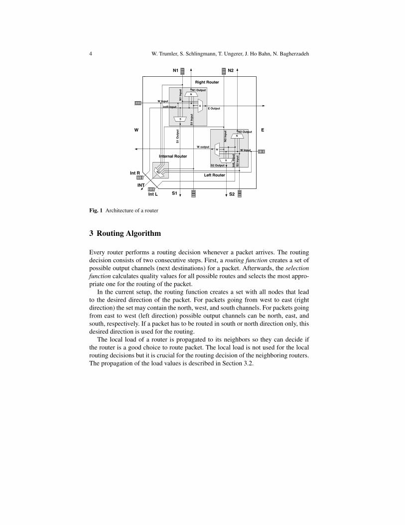
The network topology of the NoC is a 2D-mesh with NxM routers. Figure 1 showsthe architecture of a single router. The router consists of three subsections, the left,the right, and the internal router.
The task of the internal router is to inject packets into the network. Packets thatarrived at their destination are also ejected by the internal router. The left router isused to route packets to the left (west) and the right router routes packets to the right(east), respectively. Both routers can route packets to the north as well as to the southbut there is no connection between the east and west direction. This assumptiondivides the network into two separate networks where packets can go either to theeast or the west of a router, but there is no turning back in the horizontal routingdirection. This architectural approach guarantees the NoC to be dead-lock free [5].
Clock boosting was introduced to improve the performance of the NoC. A packetconsisting of multiple flits (flow control digits) can be transmitted at different clockspeeds. With clock boosting only the routing decision for the head flit is done atnormal clock speed. After the route for the packet is chosen, the body flits can berouted with an increased clock speed. By multiplying the clock frequency morethan one body flit can be routed during a normal clock cycle. The clock boostingcan double or quadruple the basic clock frequency, allowing two or four body flitsto be routed at the same time.
The routing decision of a router is straight forward using a clockwise priorityscheme to select the packets for routing. Starting from the north (top) input channelthe router examines the head flit from the buffer and tries to set the route for thispacket if possible. If there is no head flit in front of the buffer or if the route can notbe set because the output channel is already occupied by another packet, the routerpicks the next buffer in a clockwise order and repeats the aforementioned steps.More details about the clock boosting and the routing decision can be found in [13].
The internal FSM of the router is easy to implement but does not take the currentload situation of the network into account. Our approach is to improve the routingdecision by considering the current load of the neighboring routers, finding routesto avoid hot-spots. Furthermore, when the original algorithm stops routing due to acongested network, our algorithm can use alternative routes, bypassing the heavilyloaded routers, which leads to a higher overall network throughput.
4 W. Trumler, S. Schlingmann, T. Ungerer, J. Ho Bahn, N. Bagherzadeh
W Input N1 In
put
S1 In
put
IntR Input
S1 O
utpu
t
E Output
N1 Output
W Input
S2 In
put
N2 In
put
IntL
Inpu
t
N2 Output
W output
S2 Output
N
W
S
E
N
S
N1 N2
W
INT
E
S1 S2
Int R
Int L
INT
Internal Router
Right Router
Left Router
Figure 3: Adaptive router architecture.
router. The second term is serialization latency, the time fora packet of length L to cross a channel with bandwidth b.The proposed mechanism reduces the serialization latencyby boosting clock frequency during the body flit transfer.The boosting of clock frequency results in increasing thebandwidth and reduces the zero-load latency. To evaluatethe upper bound of average latency between the proposedmechanism and the original one, average latency versus of-fered traffic curves are obtained by the discrete event simu-lation in Section 6, demonstrating the performance improve-ment with the proposed mechanism.
4. BASELINE ADAPTIVE ROUTERWe propose an adaptive routing algorithm and architec-
ture for a flexible on-chip interconnection. This techniqueuses a wormhole switching technique with a deadlock- andlivelock- free algorithm for 2D-mesh topology. The pro-posed router demonstrated near-optimal performance withcomparison to O1TURN [5] in terms of average latency.Moreover the bandwidth and the total area overhead of therouter enabled the router as a feasible alternative to existingrouters for NoC. In this paper, we use the adaptive router asa baseline router and improve the throughput by adoptingthe proposed clock boosting mechanism.
4.1 OverviewWe assume the network topology in 2D-mesh which is
N×M routers. The overall block diagram of a single routeris shown in Figure 3. There is an input FIFO queue pereach input channel and each output port has an associatedarbiter to choose the proper packet among the given incom-ing packet from each candidate input port. We consider arouter with seven interfaces, suitable for a 2D-mesh with anadditional interface to an integrated processing element. Weassume that a packet coming through an input port does notloop back, thus each input port is connected to four outputports.
The router is composed of three architectural blocks: RightRouter, Left Router, and Internal Router. The Right Router
11 63
transType X-dir Y-dir No. of transfer data 61 56 55 52 51 48 31 0
DestinationPE_addr
sorucePE_addr Subdata_ID 40 39 32
Data_ID
47 groupPE_addr
15 16
data [N-1] or data[N-2] data [N-1] or null
data [0] data [1]
data [2] data [3]
Head Flit
Body Flit 1
Body Flit n
Body Flit 2
. . .
63 31 0 32
63 31 0 32
63 31 0 32
Figure 4: Packet format.
serves the port set {W-in, N1, E-out, S1}. On the contrary,the Left Router serves the port set {E-in, N2, W-out, S2}.The Internal Router supports the additional interface to anintegrated processing element. The separated routing pathsfor vertical direction and unidirectional path for horizon-tal direction allow the network avoid cycles in its channel-dependency-graph, resulting a dead lock-free operation [7,8]. Also by choosing the shortest path in routing, a livelockfree operation is guaranteed.
4.2 Packet FormatThe Figure 4 shows the packet format. Each packet has
the DestPE addr field to indicate the destination node in thehead flit. The address of the destination node is representedby relative distance of horizontal and vertical direction. Apositive value represents southern and eastern direction invertical and horizontal direction, respectively. Each relativedistance is signed magnitude value, i.e. MSB of each X-dirand Y-dir field represents its sign and the rest of bits repre-sent its magnitude. For instance, if destPE addr has 0x91 inhexadecimal format, it represents that the destination nodeis located at western 1 hop and southern 1 hop from thecurrent node. Its vectorized representation in X − Y coor-dinate is (-1, 1). The head flit also has the No of Flits fieldto represent the number of body flits followed by the headflit.
4.3 PriorityFor outgoing channel allocation, the router applies a fixed
priority scheme to the incoming packets that have reachedthe corresponding node simultaneously. For each outgoingchannel, the possible incoming channels have a descendingorder of priority in a clock-wise direction. Similarly, eachoutput port has a descending order of priority in clock-wisedirection from N1. The incoming packets and output portof an internal router have the lowest priority.
4.4 Router ArchitectThe detail block diagram of the Right Router is shown in
Figure 5. The routers for each output port are placed ac-cording to their priority level from the highest router (N1 ) tothe lowest router (S1 ). Each incoming packet is directed tothe Header Parsing Unit (HPU ) per each output port. TheHPU generates a set of possible incoming packets, whichcould be routed to the corresponding output port, in or-der of the input priority level by looking up the destinationaddress in the head flit.
When the output port is available(by referencing FULLsignal), the router chooses the input packet for the corre-sponding output port among the set of routable incomingentries provided by the HPU. If two or more packets arrivesimultaneously, the arbiter will choose a packet according totheir priority.
Fig. 1 Architecture of a router
3 Routing Algorithm
Every router performs a routing decision whenever a packet arrives. The routingdecision consists of two consecutive steps. First, a routing function creates a set ofpossible output channels (next destinations) for a packet. Afterwards, the selectionfunction calculates quality values for all possible routes and selects the most appro-priate one for the routing of the packet.
In the current setup, the routing function creates a set with all nodes that leadto the desired direction of the packet. For packets going from west to east (rightdirection) the set may contain the north, west, and south channels. For packets goingfrom east to west (left direction) possible output channels can be north, east, andsouth, respectively. If a packet has to be routed in south or north direction only, thisdesired direction is used for the routing.
The local load of a router is propagated to its neighbors so they can decide ifthe router is a good choice to route packet. The local load is not used for the localrouting decisions but it is crucial for the routing decision of the neighboring routers.The propagation of the load values is described in Section 3.2.
Self-optimized Routing in a Network-on-a-Chip 5
3.1 Self-Optimization-Algorithm
3.1.1 Selection Function
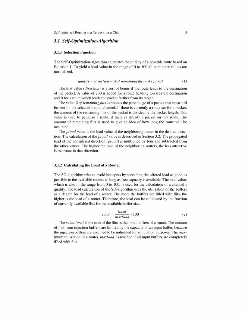
The Self-Optimization-algorithm calculates the quality of a possible route based onEquation 1. To yield a load value in the range of 0 to 100 all parameter values arenormalized.
quality = direction−%of remaining flits−4∗ pload (1)
The first value (direction) is a sort of bonus if the route leads to the destinationof the packet. A value of 200 is added for a route heading towards the destinationand 0 for a route which leads the packet farther from its target.
The value %of remaining flits expresses the percentage of a packet that must stillbe sent on the selected output channel. If there is currently a route set for a packet,the amount of the remaining flits of the packet is divided by the packet length. Thisvalue is used to penalize a route, if there is already a packet on that route. Theamount of remaining flits is used to give an idea of how long the route will beoccupied.
The pload value is the load value of the neighboring router in the desired direc-tion. The calculation of the pload value is described in Section 3.2. The propagatedload of the considered direction (pload) is multiplied by four and subtracted fromthe other values. The higher the load of the neighboring routers, the less attractiveis the route in that direction.
3.1.2 Calculating the Load of a Router
The SO-algorithm tries to avoid hot-spots by spreading the offered load as good aspossible to the available routers as long as free capacity is available. The load value,which is also in the range from 0 to 100, is used for the calculation of a channel’squality. The load calculation of the SO-algorithm uses the utilization of the buffersas a degree for the load of a router. The more the buffers are filled with flits, thehigher is the load of a router. Therefore, the load can be calculated by the fractionof currently available flits for the available buffer size.
load =local
maxload∗100 (2)
The value local is the sum of the flits in the input buffers of a router. The amountof flits from injection buffers are limited by the capacity of an input buffer, becausethe injection buffers are assumed to be unlimited for simulation purposes. The max-imum utilization of a router, maxload, is reached if all input buffers are completelyfilled with flits.
6 W. Trumler, S. Schlingmann, T. Ungerer, J. Ho Bahn, N. Bagherzadeh
South
North
West
pload
pload
pload
pload
Input
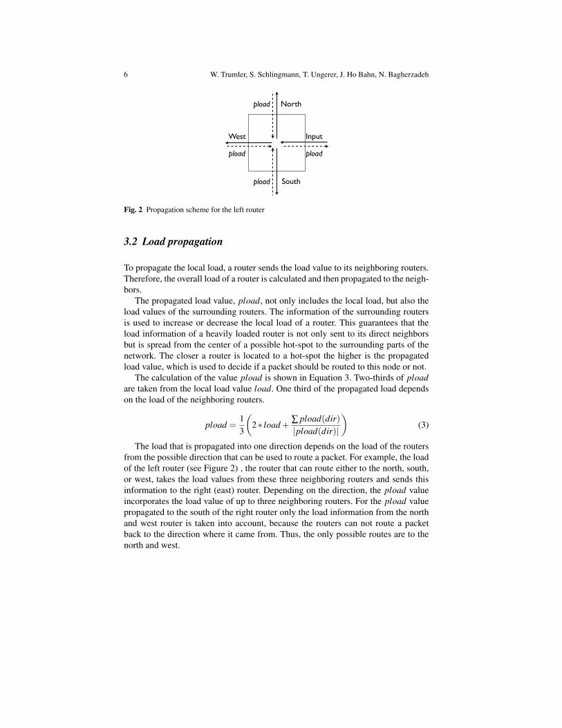
Fig. 2 Propagation scheme for the left router
3.2 Load propagation
To propagate the local load, a router sends the load value to its neighboring routers.Therefore, the overall load of a router is calculated and then propagated to the neigh-bors.
The propagated load value, pload, not only includes the local load, but also theload values of the surrounding routers. The information of the surrounding routersis used to increase or decrease the local load of a router. This guarantees that theload information of a heavily loaded router is not only sent to its direct neighborsbut is spread from the center of a possible hot-spot to the surrounding parts of thenetwork. The closer a router is located to a hot-spot the higher is the propagatedload value, which is used to decide if a packet should be routed to this node or not.
The calculation of the value pload is shown in Equation 3. Two-thirds of ploadare taken from the local load value load. One third of the propagated load dependson the load of the neighboring routers.
pload =13
(2∗ load + ∑ pload(dir)
|pload(dir)|
)(3)
The load that is propagated into one direction depends on the load of the routersfrom the possible direction that can be used to route a packet. For example, the loadof the left router (see Figure 2) , the router that can route either to the north, south,or west, takes the load values from these three neighboring routers and sends thisinformation to the right (east) router. Depending on the direction, the pload valueincorporates the load value of up to three neighboring routers. For the pload valuepropagated to the south of the right router only the load information from the northand west router is taken into account, because the routers can not route a packetback to the direction where it came from. Thus, the only possible routes are to thenorth and west.
Self-optimized Routing in a Network-on-a-Chip 7
4 Evaluations
We conducted extensive experiments with different network sizes ranging from 4x4up to 16x16. Next, we will describe the traffic patterns used for the generation ofthe network load and discuss the results for a 4x4 and 8x8 2D-mesh network incomparison to the results of the design from the University of California in Irvine.Afterwards, we compare the performance gain of the network in terms of increasednetwork throughput.
4.1 Traffic generation
We evaluated our algorithms with four different traffic patterns as proposed in [7](Chapter 9). We used the same four traffic patterns as they did at the UCI to have abasis for a direct comparison of the results.
The traffic patterns used are matrix transpose, bit reverse, bit complement, anduniform random. The target address of a packet is generated out of the source ad-dress of a node by applying one of the aforementioned traffic patterns. For thesesimulations, the width and height of the 2D-mesh network is assumed to be a powerof two. Without this assumption some of the traffic patterns might produce invaliddestination addresses.
For every simulation setup, we conducted multiple runs and calculated the aver-age network latency to minimize the impact of possibly good circumstances in onesimulation run. The network had a warm-up phase of 1000 cycles at the beginning ofevery simulation. The measurement was done during 100,000 cycles following thewarm-up phase. The simulation stopped if the average delay of the packets exceededa threshold of 200 cycles.
The injection of the flits was chosen to be the worst case, which means, that allnodes inject their flits at the same time resulting in a high network load. Assumingthat the nodes would distribute the flit injection over time, the results are even betterthan shown in the charts.
The packet injection rate can be calculated from the injection rate of the flits. Inour simulations, we used a fixed packet length of nine flits (one head flit and eightbody flits). Therefore, the packet injection rate can be calculated by dividing the flitinjection rate by nine.
4.2 4x4 NoC
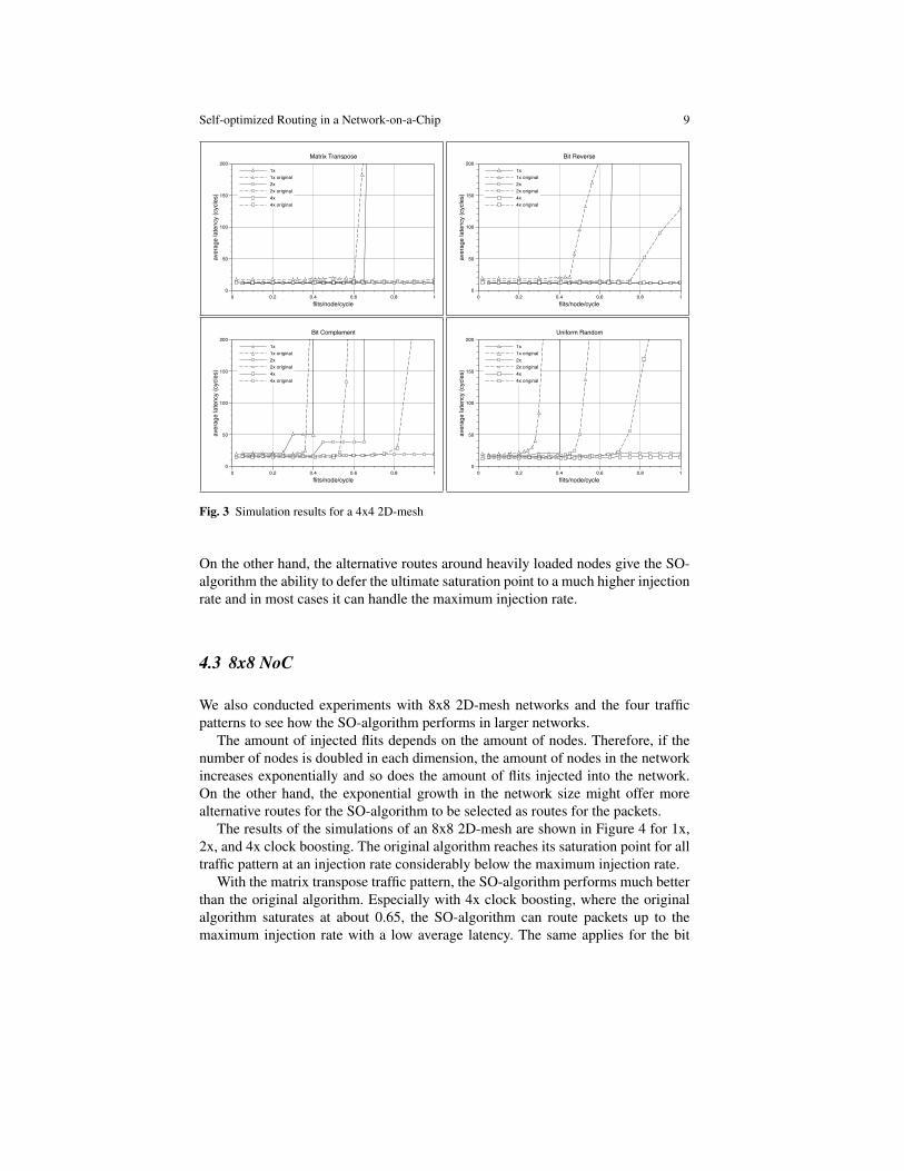
The first simulations were done on a 4x4 2D-mesh with the aforementioned trafficpatterns. The results are shown in Figure 3. The charts show the generated trafficon the x-axis and the measured average latency on the y-axis. The generated trafficis given in flits per node per cycle which is a value ranging from 0.05 to 1. If the

8 W. Trumler, S. Schlingmann, T. Ungerer, J. Ho Bahn, N. Bagherzadeh
generated traffic is 1, a new flit is injected into the internal buffer of the routersat every node in every cycle. If the traffic is below 1, there are a few cycles delaybetween the injection of new flits, e.g. at 0.5 a new flit is injected every second cycle.
For a direct comparison of the results from Irvine and our results, we plottedall the data into one chart. Every chart shows the results with 1x, 2x, and 4x clockboosting for both.
Concerning the matrix transpose traffic pattern there is hardly any improvementof the SO-algorithm compared with the original algorithm. Both can route all pack-ets with a nearly constant delay up to the maximum load, if the clock boosting isused. The saturation point of the network seems to be about the same for both algo-rithms.
The bit reverse traffic pattern first shows considerable differences. The saturationpoint for the SO-algorithm is about 0.65 and about 0.45 for the original algorithmwithout clock boosting. The maximum throughput of the SO-algorithm is even bet-ter for the 2x clock boosting. While the original algorithm begins to saturate at about0.8, the SO-algorithm routes all packets with nearly the same delay up to the maxi-mum injection rate. The results with 4x clock boosting are again the same for bothalgorithms.
Bit complement traffic shows interesting results in terms of the algorithms sat-uration points. The original algorithm has a saturation point of 0.35, 0.5, and 0.85,respectively. The SO-algorithm first increases the latency, which creates a kind ofplateau phase. This plateau has a different length for different clock boosting values.The plateau also appears at the 4x clock boosting, but the SO-algorithm can routeall the packets with only a slight latency increase up to the maximum injection rateand does not reach the saturation point.
The uniform random traffic pattern seems to be the hardest of all four trafficpatterns, because the saturation point of the original algorithm is reached earliest.The SO-algorithm shows very good behavior especially for the 2x and 4x clockboosting. In both cases, the SO-algorithm does not reach the saturation point butcan route all packets up to the maximum injection rate. The uniform random trafficpattern shows similar behavior for the SO-algorithm than in the previous trafficpattern. There are two plateaus for the 1x and 2x clock boosting at different injectionrates. The first plateau is also visible for the 4x clock boosting but the second onedoes not appear.
The explanation for the appearance of the plateaus can be derived from the waythe SO-algorithm selects the routes for the destination of a packet. As long as thereare enough good alternative routes to the destination, the SO-algorithm automati-cally selects the next best (shortest) path. For example, a packet at the node (1,1)should be routed to (3,2) and if the buffers of the router to the east (2,1) are filled,the SO-algorithm routes the packet to (1,2) instead. If the injection rate increases,more buffers are completely filled and more congestions arise in the network. Atthe same time, since the quality of the alternative routers are also getting worse, theSO-algorithm selects routes by avoiding both shortest but heavily loaded routes.
If the SO-algorithm starts routing packets not on one of the shortest paths, theaverage latency increases due to the additional hops and the possible congestions.
Self-optimized Routing in a Network-on-a-Chip 9
0 0.2 0.4 0.6 0.8 1flits/node/cycle
0
50
100
150
200
aver
age
late
ncy
(cyc
les)
1x1x original2x2x original4x4x original
Matrix Transpose
0 0.2 0.4 0.6 0.8 1flits/node/cycle
0
50
100
150
200
aver
age
late
ncy
(cyc
les)
1x1x original2x2x original4x4x original
Bit Reverse
0 0.2 0.4 0.6 0.8 1flits/node/cycle
0
50
100
150
200
aver
age
late
ncy
(cyc
les)
1x1x original2x2x original4x4x original
Bit Complement
0 0.2 0.4 0.6 0.8 1flits/node/cycle
0
50
100
150
200
aver
age
late
ncy
(cyc
les)
1x1x original2x2x original4x4x original
Uniform Random
Fig. 3 Simulation results for a 4x4 2D-mesh
On the other hand, the alternative routes around heavily loaded nodes give the SO-algorithm the ability to defer the ultimate saturation point to a much higher injectionrate and in most cases it can handle the maximum injection rate.
4.3 8x8 NoC
We also conducted experiments with 8x8 2D-mesh networks and the four trafficpatterns to see how the SO-algorithm performs in larger networks.
The amount of injected flits depends on the amount of nodes. Therefore, if thenumber of nodes is doubled in each dimension, the amount of nodes in the networkincreases exponentially and so does the amount of flits injected into the network.On the other hand, the exponential growth in the network size might offer morealternative routes for the SO-algorithm to be selected as routes for the packets.
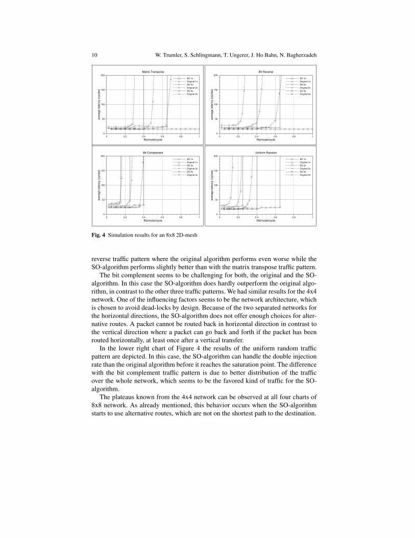
The results of the simulations of an 8x8 2D-mesh are shown in Figure 4 for 1x,2x, and 4x clock boosting. The original algorithm reaches its saturation point for alltraffic pattern at an injection rate considerably below the maximum injection rate.
With the matrix transpose traffic pattern, the SO-algorithm performs much betterthan the original algorithm. Especially with 4x clock boosting, where the originalalgorithm saturates at about 0.65, the SO-algorithm can route packets up to themaximum injection rate with a low average latency. The same applies for the bit
10 W. Trumler, S. Schlingmann, T. Ungerer, J. Ho Bahn, N. Bagherzadeh
0 0.2 0.4 0.6 0.8 1flits/node/cycle
0
50
100
150
200
aver
age
late
ncy
(cyc
les)
SO 1xOriginal 1xSO 2xOriginal 2xSO 4xOriginal 4x
Matrix Transpose
0 0.2 0.4 0.6 0.8 1flits/node/cycle
0
50
100
150
200
aver
age
late
ncy
(cyc
les)
SO 1xOriginal 1xSO 2xOriginal 2xSO 4xOriginal 4x
Bit Reverse
0 0.2 0.4 0.6 0.8 1flits/node/cycle
0
50
100
150
200
aver
age
late
ncy
(cyc
les)
SO 1xOriginal 1x SO 2xOriginal 2xSO 4xOriginal 4x
Bit Complement
0 0.2 0.4 0.6 0.8 1flits/node/cycle
0
50
100
150
200
aver
age
late
ncy
(cyc
les)
SO 1xOriginal 1xSO 2xOriginal 2xSO 4xOriginal 4x
Uniform Random
Fig. 4 Simulation results for an 8x8 2D-mesh
reverse traffic pattern where the original algorithm performs even worse while theSO-algorithm performs slightly better than with the matrix transpose traffic pattern.
The bit complement seems to be challenging for both, the original and the SO-algorithm. In this case the SO-algorithm does hardly outperform the original algo-rithm, in contrast to the other three traffic patterns. We had similar results for the 4x4network. One of the influencing factors seems to be the network architecture, whichis chosen to avoid dead-locks by design. Because of the two separated networks forthe horizontal directions, the SO-algorithm does not offer enough choices for alter-native routes. A packet cannot be routed back in horizontal direction in contrast tothe vertical direction where a packet can go back and forth if the packet has beenrouted horizontally, at least once after a vertical transfer.
In the lower right chart of Figure 4 the results of the uniform random trafficpattern are depicted. In this case, the SO-algorithm can handle the double injectionrate than the original algorithm before it reaches the saturation point. The differencewith the bit complement traffic pattern is due to better distribution of the trafficover the whole network, which seems to be the favored kind of traffic for the SO-algorithm.
The plateaus known from the 4x4 network can be observed at all four charts of8x8 network. As already mentioned, this behavior occurs when the SO-algorithmstarts to use alternative routes, which are not on the shortest path to the destination.
Self-optimized Routing in a Network-on-a-Chip 11
4.4 Performance comparison
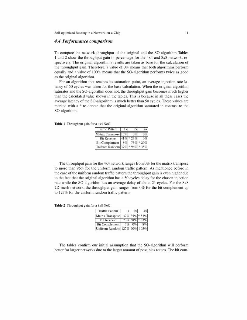
To compare the network throughput of the original and the SO-algorithm Tables1 and 2 show the throughput gain in percentage for the 4x4 and 8x8 network, re-spectively. The original algorithm’s results are taken as base for the calculation ofthe throughput gain. Therefore, a value of 0% means that both algorithms performequally and a value of 100% means that the SO-algorithm performs twice as goodas the original algorithm.
For an algorithm that reaches its saturation point, an average injection rate la-tency of 50 cycles was taken for the base calculation. When the original algorithmsaturates and the SO-algorithm does not, the throughput gain becomes much higherthan the calculated value shown in the tables. This is because in all these cases theaverage latency of the SO-algorithm is much better than 50 cycles. These values aremarked with a * to denote that the original algorithm saturated in contrast to theSO-algorithm.
Table 1 Throughput gain for a 4x4 NoC
Traffic Pattern 1x 2x 4xMatrix Transpose 13% 0% 0%
Bit Reverse 41% * 23% 0%Bit Complement 8% 75% * 20%Unifrom Random 37% * 96% * 35%
The throughput gain for the 4x4 network ranges from 0% for the matrix transposeto more than 96% for the uniform random traffic pattern. As mentioned before inthe case of the uniform random traffic pattern the throughput gain is even higher dueto the fact that the original algorithm has a 50 cycles delay for the chosen injectionrate while the SO-algorithm has an average delay of about 21 cycles. For the 8x82D-mesh network, the throughput gain ranges from 0% for the bit complement upto 127% for the uniform random traffic pattern.
Table 2 Throughput gain for a 8x8 NoC
Traffic Pattern 1x 2x 4xMatrix Transpose 37% 35% * 53%
Bit Reverse 73% 58% * 63%Bit Complement 7% 0% 8%Unifrom Random 127% 90% 103%
The tables confirm our initial assumption that the SO-algorithm will performbetter for larger networks due to the larger amount of possibles routes. The bit com-
12 W. Trumler, S. Schlingmann, T. Ungerer, J. Ho Bahn, N. Bagherzadeh
plement is the sole exception to this assumption. Further investigations are neededto better understand the reasons for the poor throughput gain in this case.
5 Related Work
In designing Network-on-a-Chip (NoC) systems, there are several issues to be con-sidered, such as topology, routing algorithm, performance, latency, and complexity.Because of its flexibility, architectures based on NoC are getting more attention. Asa feasible topology in NoC systems, the mesh is getting popular for its modularity;it can be easily expanded by adding new nodes and links without any modificationof the existing node structure.
Another issue in NoC environment is the routing algorithm. In terms of deliver-ing mechanism, wormhole routing has increasingly been advocated as a method ofreducing message routing latency. In wormhole routing, a packet is decomposed intoflits or flow control units, and the packet follows through the network one flit afteranother. On the other hand, in terms of the way of selecting a path among the setsof possible paths from source to destination, the routing algorithms are classified asdeterministic/oblivious and adaptive ones [5]. The oblivious/deterministic routingalgorithms choose a route without considering any information about the network’spresent condition, resulting in relatively simple design complexity. Adaptive rout-ing algorithms use the state of the network such as the status of a node or link,the status of buffers for network resources, or history of channel load information.Even though the adaptive routing algorithms utilize the flexibility in routing paths,the hardware design complexity is usually increased. Depending on the degree ofadaptivity, minimal adaptive and fully adaptive routing algorithms are refined. DOR(dimension-ordered routing) [19], ROMM [14], and O1TURN [18] are examples ofdeterministic or oblivious algorithms. Some researchers have developed better per-formance routing algorithms using adaptive routing algorithms [10, 4, 6, 2, 9, 8].The SO-algorithm is an adaptive routing algorithm that does not use virtual chan-nels.
The adoption of virtual channel (abbreviated to VC) has been prevailing becauseof its versatility. By adding virtual channels and proper utilization of their chan-nels, deadlock-freedom can be easily accomplished. Network throughput can beincreased by dividing the buffer storage associated with each network channel intoseveral virtual channels. By proper control of virtual channels, network flow controlcan be easily implemented [3]. Also to increase the fault tolerance in a network, theconcept of virtual channel has been utilized [1, 12]. However, in order to maximizeits utilization, allocation of virtual channels is a critical issue in designing routingalgorithms [22, 16]. Furthermore, the buffers of the virtual channels are very ex-pensive in terms of chip size. The extra chip size needed for the additional logic ofour SO-algorithm is negligible compared to the chip size needed for the buffers ofvirtual channels and the logic for the channel allocation.
Self-optimized Routing in a Network-on-a-Chip 13
A similar approach, using stress values, is described in [15]. The stress valuesare exchanged between the direct neighbors in the network. With our calculationsthe load value is not only exchanged with the direct neighbors, but diffuses to thesurrounding area of load value’s source. Furthermore, there are less choices for ouralgorithm to chose the best routes due to the two separated networks, which guar-antee deadlock free routing by design.
6 Conclusion and Future Work
In this paper we presented a routing algorithm for an Network-on-a-Chip that yieldsa significant throughput gain for 2D-mesh networks. The SO-algorithm calculatesthe load of a router based on the amount of flits in the buffers. With this approachthe network throughput can be significantly increased. The throughput gain is upto 127% compared to the original algorithm. The throughput gain is highest for theuniform random traffic pattern, which in our opinion is especially relevant for ourcurrent research where we will investigate task allocation mechanisms on an NoC.The expected traffic in such a dynamic and steadily changing environment will leadto a traffic pattern comparable to the uniform random.
Based on our latest results, we have plenty of ideas to improve the SO-algorithm.The first will be to combine the SO-algorithm with another approaches that is de-scribed in [17]. The idea is to use the SO-algorithm as a base value for the local loadand to increase or decrease it by the amount of I/O operations a router can processduring a cycle. If the input channels of a router are filled with flits, the router isloaded to a level of 100% (concerning the SO-algorithm) but the situation is aggra-vated if the router is blocked and cannot perform any read or write operations. Onthe other hand, if the router is full but can transfer a maximum number of flits, itmight be a better choice.
References
1. S. Chalasani and R. V. Boppana. Fault-tolerant wormhole routing algorithms for mesh net-works. IEEE Trans. Comput., 44(7):848–864, 1995.
2. G.-M. Chiu. The odd-even turn model for adaptive routing. IEEE Trans. Parallel Distrib.Syst., 11(7):729–738, 2000.
3. W. J. Dally. Virtual-channel flow control. In 17th annual international symposium on Com-puter Architecture (ISCA ’90), pages 60–68, New York, NY, USA, 1990. ACM.
4. W. J. Dally and C. L. Seitz. Deadlock-free message routing in multiprocessor interconnectionnetworks. IEEE Trans. Comput., 36(5):547–553, 1987.
5. W. J. Dally and B. Towles. Principles and Practices of Interconnection Networks. MorganKaufmann Publishers, 2004.
6. J. Duato. A new theory of deadlock-free adaptive routing in wormhole networks. IEEE Trans.Parallel Distrib. Syst., 4(12):1320–1331, 1993.
7. J. Duato, S. Yalamanchili, and L. Ni. Interconnection Networks – An Engineering Approach.Morgan Kaufmann Publishers, 2003.
8. C. J. Glass and L. M. Ni. Maximally fully adaptive routing in 2D meshes. In Proceedingsof the 1992 International Conference on Parallel Processing, volume I, Architecture, pagesI:101–104, Boca Raton, Florida, 1992. CRC Press.
14 W. Trumler, S. Schlingmann, T. Ungerer, J. Ho Bahn, N. Bagherzadeh
9. C. J. Glass and L. M. Ni. The turn model for adaptive routing. J. ACM, 41(5):874–902, 1994.10. J. Hu and R. Marculescu. Dyad - smart routing for network-on-chip. In 41-st Annual Conf.
on Design and Automation, pages 260–263, 2004.11. Intel Corporation. Intel’s teraflops research chip. http://download.intel.com/research/platform/
terascale/teraflops/ FINAL TeraflopsResearchChip Overview.pdf, November 2007.12. F. Jipeng Zhou; Lau. Adaptive fault-tolerant wormhole routing with two virtual channels in
2d meshes. Parallel Architectures, Algorithms and Networks, 2004. Proceedings. 7th Interna-tional Symposium on, pages 142–148, 10-12 May 2004.
13. S. E. Lee and N. Bagherzadeh. Increasing the throughput of an adaptive router in network-on-chip (noc). In 3rd International Conference on Hardware-Software Codesign and SystemSynthesis (CODES+ISSS), Seoul, Korea, Oktober 22-25 2006. ACM.
14. T. Nesson and S. L. Johnsson. ROMM routing on mesh and torus networks. In Proc. 7thAnnual ACM Symposium on Parallel Algorithms and Architectures SPAA’95, pages 275–287,Santa Barbara, California, 1995.
15. E. Nilsson, M. Millberg, J. Oberg, and A. Jantsch. Load distribution with the proximity con-gestion awareness in a network on chip. In DATE ’03: Proceedings of the conference onDesign, Automation and Test in Europe, pages 11126–11127, Washington, DC, USA, March2003. IEEE Computer Society.
16. H. Rezazad, M.; Sarbazi-azad. The effect of virtual channel organization on the performanceof interconnection networks. Parallel and Distributed Processing Symposium, 2005. Proceed-ings. 19th IEEE International, pages 8 pp.–, 4-8 April 2005.
17. S. Schlingmann. Selbstoptimierendes routing in einem network-on-a-chip. Master’s thesis,University of Augsburg, September 2007.
18. D. Seo, A. Ali, W.-T. Lim, and N. Rafique. Near-optimal worst-case throughput routing fortwo-dimensional mesh networks. In 32nd International Symposium on Computer Architecture,2005. ISCA ’05, pages 432–443, Madison, Wisconsin USA, 4-8 June 2005.
19. H. Sullivan and T. R. Bashkow. A large scale, homogeneous, fully distributed parallel ma-chine, i. In ISCA ’77: Proceedings of the 4th annual symposium on Computer architecture,pages 105–117, New York, NY, USA, 1977. ACM.
20. W. Trumler, T. Thiemann, and T. Ungerer. An artificial hormone system for self-organizationof networked nodes. In IFIP Conference on Biologically Inspired Cooperative Computing,pages 85–94, Santiago de Chile, August 2006. Springer-Verlag.
21. A. M. Turing. The chemical basis of morphogenesis. Philosophical Transactions of the RoyalSociety of London. Series B, Biological Sciences, 237(641):37–72, August 1952.
22. A. S. Vaidya, A. Sivasubramaniam, and C. R. Das. Impact of virtual channels and adaptiverouting on application performance. IEEE Trans. Parallel Distrib. Syst., 12(2):223–237, 2001.


![[OER] Cisco IOS Optimized Edge Routing Configuration.](https://static.fdocuments.in/doc/165x107/5532f4c74a7959ae4b8b479d/oer-cisco-ios-optimized-edge-routing-configuration.jpg)