
Self-modelling organizer for interior storage
106
DIVISION OF PRODUCT DEVELOPMENT FACULTY OF ENGINEERING LTH • LUND UNIVERSITY • 2017 MASTER THESIS Shuang Hansen Self-modelling organizer for interior storage
Transcript of Self-modelling organizer for interior storage

DIVISION OF PRODUCT DEVELOPMENT
FACULTY OF ENGINEERING LTH • LUND UNIVERSITY • 2017
MASTER THESIS
Shuang Hansen
Self-modelling organizer for interior storage
Self- modelling organizer for interior storage
Shuang Hansen

Self- modelling organizer for interior storage Copyright © 2017
Published by
Division of product development, Department of Design Science Faculty of Engineering LTH, Lund University
P.O. Box 118 SE-221 00 Lund, Sweden
Subject: Product Development (MMKM05)
Supervisor: Damien Motte
Examiner: Olaf Diegel

Abstract
Today's urbanization creates big cities. More and more people are facing the problem with the increasing housing prices, and they had often to live in small or shared apartments. Most of the kitchens in those apartments are often small, which leads to a increasing need to use the available space in a more efficient way.
An investigation conducted for the existing solutions in the market, has revealed a potential need of more flexible and customer - adapted organising products.
A concept idea was caught my interest, which use a pegboard at the bottom of a deep drawer with wood dowels or walls as dividers and guides, to keep items from shifting and chipping each other. In that way, the user can organise the items after their own needs. However, there is not a existing product use the similar concept or can be purchased in the market.
The objective of the thesis work is to develop the concept idea to a product with a production and custom friendly design, material solution and flexible using areas by using the knowledge of the production development.
The initial phase began with a market investigation, where identified the market potential, existing solutions and universal kitchen dimensions, and then an experimental prototype was built and tested by interviewee to collect needs and feedbacks for further developing. After the main features were defined (fixation and assembly solution), the first initial prototype was sketched in a CAD model and used to execute the mechanical, moulding and cost analysis to optimize the design in a cost-efficient way and fulfil the necessary requirements. However, due to limitation of time and resources, some of requirements such as price, appearance were not fulfilled in the end of the project, and the prototype is still in need of improvements before manufacturing. An example is a retail price for a small cutlery holder came up 160 kr, which cost 2, 5 times more than the target price.
Keywords: Interior organiser, Self-modelling, Dowel, Dimension, Pegboard.

Acknowledgments
I wish to express my most sincere thanks to my supervisor Damien Motte who gave me patient guidance and support throughout the duration of my master thesis and was always willing to make time for me when I encountered issues. It was both an honour and a pleasure to learn from such knowledgeable yet approachable man.
I would also like to extend my gratitude to my examiner Professor Olaf Diegel. His insightful contributions to the direction of the thesis were greatly appreciated. I am also indebted to him for helping me get into right track with this thesis when I was confused and uncertain about the idea.
Lastly, I would like to thank my family and my fiancé for supporting me through good times and bad during my time at Lund. In particular, my fiancé who lovingly believed in me and very generously gave me all the support I need under my study time.
Lund, October 2017
Shuang Hansen
Table of contents List of abbreviations 10
1 Introduction 11
1.1 Background 11
1.2 Starting point 12
1.3 Description of the concept idea 13
1.4 Objectives and aims 13
1.5 User 14
1.6 Methods 14
1.6.1 The development processes 14
1.6.2 Project plan 14
1.7 Structure of the thesis 16
2 Prestudy 18
2.1 Patents search 18
2.1.1 Conclusion of the patents search 18
2.2 Market investigation 19
2.2.1 Modern kitchen manufacture 19
2.2.2 Conclusion of market investigation 22
2.3 The dimension of base drawer 22
2.3.1 Kitchen manufactures 23
2.3.2 Student apartments and private rental company 24
2.4 The first experimental prototypes 25
3 Concept testing 27
3.1 Define the purpose of the concept test 27
3.2 Choose a survey population 28
3.3 Choose a survey format 29
3.3 Communicate the concept 30
3.4 Measure customer response 30
3.5 Interpret the results 30
3.5.1 The results of the testing 30
3.6 The final specifications 33

4 System level design 34
4.1 Develop product architecture 34
4.1.1 The arrangement of functional elements 34
4.1.2 Mapping from functional elements to physical components 35
4.1.3 Determine the interfaces among interacting physical components 36
4.2 Refine industrial design 37
4.2.1 The walls 37
4.2.2 The bottom plank 39
4.2.3 The dowels 40
5 Detail design 41
5.1 Fixation solution 41
5.1.1 Research 42
5.1.2 Concepts for fixation solution 44
5.2 Edge assembly 46
6 Material selection 47
6.1 Establishing the requirement specifications 47
6.1.1 MUST requirements 47
6.1.2 Want requirements 48
6.2 Specify and sort the material candidates 48
6.3 Further valuation of the material candidates 51
7 Define Parts geometry 52
7.1 Final fixation solution 52
7.1.1 Material input 52
7.1.2 Part’s geometry changes for testing 53
7.1.3 Contact strain and mesh setting 53
7.1.4 Testing environment 55
7.1.5 Results of simulation 56
7.1.6 Define final fixation solutions 60
7.2 Design challenges of straight beam cantilever snap fit 61
7.3 Design for manufacturing 66
7.3.1 Wall thickness 66
7.3.2 Uniform walls 66

7.3.3 Corner design 66
7.4 Assign tolerances 67
7.5 The bottom plank 68
7.6 The dowel 69
7.7 The wall 70
8 Testing and refinement 71
8.1 Parts testing in Ansys 71
8.2 Testing environment 71
8.3 Results of the testing 75
8.4 Moulding 76
8.4.1 Mounding process 76
8.4.2 Moulding analysis 76
8.5 Cost analysis 78
8.5.1 Background of input parameters 78
8.5.2 Parts price 79
9 Prototyping 80
9.1 3D print 80
9.2 Valuation of the prototype 82
9.3 Render prototype in Creo 83
10 Conclusion and discussion 84
10.1 Fulfilment of specifications and requirements 84
10.2 Further work 85
10.2.1 The sale unit 85
10.2.2 Better and smarter assembly solutions 85
10.2.3 Reduce parts cost 85
10.2.4 Further end user test 86
10.2.5 Integral the walls solutions 86
10.2.6 More advanced mould analysis 86
10.3 Reflection 87
References 88
Appendix A Work time plan 91
Appendix B The interview templates 92

Appendix C Calculations 94
Appendix D Drawing for parts 97
Appendix E Results of the testing 101
Appendix F Tool cost detail 104

10
List of abbreviations
SMO Self modelling organizer
WPS Work breakdown structure
CAD Computer aided design
FEM Finite element method
ABS Acrylonitrile butadiene styrene
POM Polyoxymethylene
DIN German Institute for Standardization
UV Ultraviolet
PE Polyethylene

11
1 Introduction
The first chapter is an introduction describing the underlying conditions and problem definition of the thesis work, user, purpose, aims and the structure.
1.1 Background
The urbanization creates big cities and towns where people get better and more diverse jobs. However, the pricing for living increases dramatically, which makes rentals and small apartments popular. One of the biggest problems faced in modern day homes is the lack of storage space [1]. This is particularly true in the kitchen where a lot of gadgets and appliances are used.
The idea started when I had difficulties with organising my lunch boxes, they take a lots space and it is difficult to find the right cover. The same problem occurred with the plates and others dinner set see figure 1.1. The issues recognized even by many of the closed family and friends. An investigation started to search solutions or existing products to deal with the issue, a concept idea came into notice.
Figure 1.1 Some examples of organising issues.

12
The concept idea come from a website [2] where many public kitchen organiser tricks are presented. The idea is using a pegboard at the bottom of a deep drawer with wood dowels or walls as dividers and guides, to keep items from shifting and chipping each other. In this way, the user can organise the items after their own needs see figure 1.2.
1.2 Starting point
The starting point for this project is a concept idea, can be further developed into a end and flexible product which meet the custom and manufacturing demand with right material, quality and low cost. Therefore, the focus of this thesis isn’t generating new concepts, but the process of how a concept converts into a manufacturing purpose.
Figure 1.2 The organizer tricks

13
1.3 Description of the concept idea
The concept idea named self-modelling organiser, SMO, can be described as two main parts, a bottom plank with fixation solution like holes and several partition applications with attachment like a pegboard. The bottom plank has assembly pattern so that several bottom planks can be putted together to fit different sizes of the drawers or cabinet. The partition application can have various shapes to easier partition area on the bottom plank. For instants, a box shape, where the cutlery and small items can be fitted in. A dowel, can provide support to items to keep them in the desired place. Or maybe a dowel with angle, which used to provide support to plates so the plates can stand and fit into lower cabinet. Furthermore, a wall which can create a bigger organising area at one time. An illustration of the concept idea is presented figure 1.3.
1.4 Objectives and aims
The purpose of this thesis is to test and further develop the concept to a real product which is ready for manufacturing. The objectives of the thesis are also to provide an opportunity for low income group and apartment rental group to organize their interior storage, to be able to use more of their kitchen area in an affordable way.
Figure 1.3 The concept, inspired from tricks.
14
1.5 User
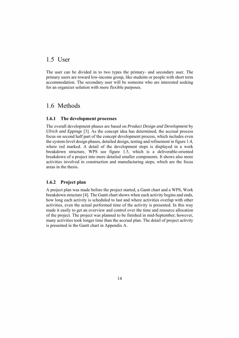
The user can be divided in to two types the primary- and secondary user. The primary users are toward low-income group, like students or people with short term accommodation. The secondary user will be someone who are interested seeking for an organizer solution with more flexible purposes.
1.6 Methods
1.6.1 The development processes
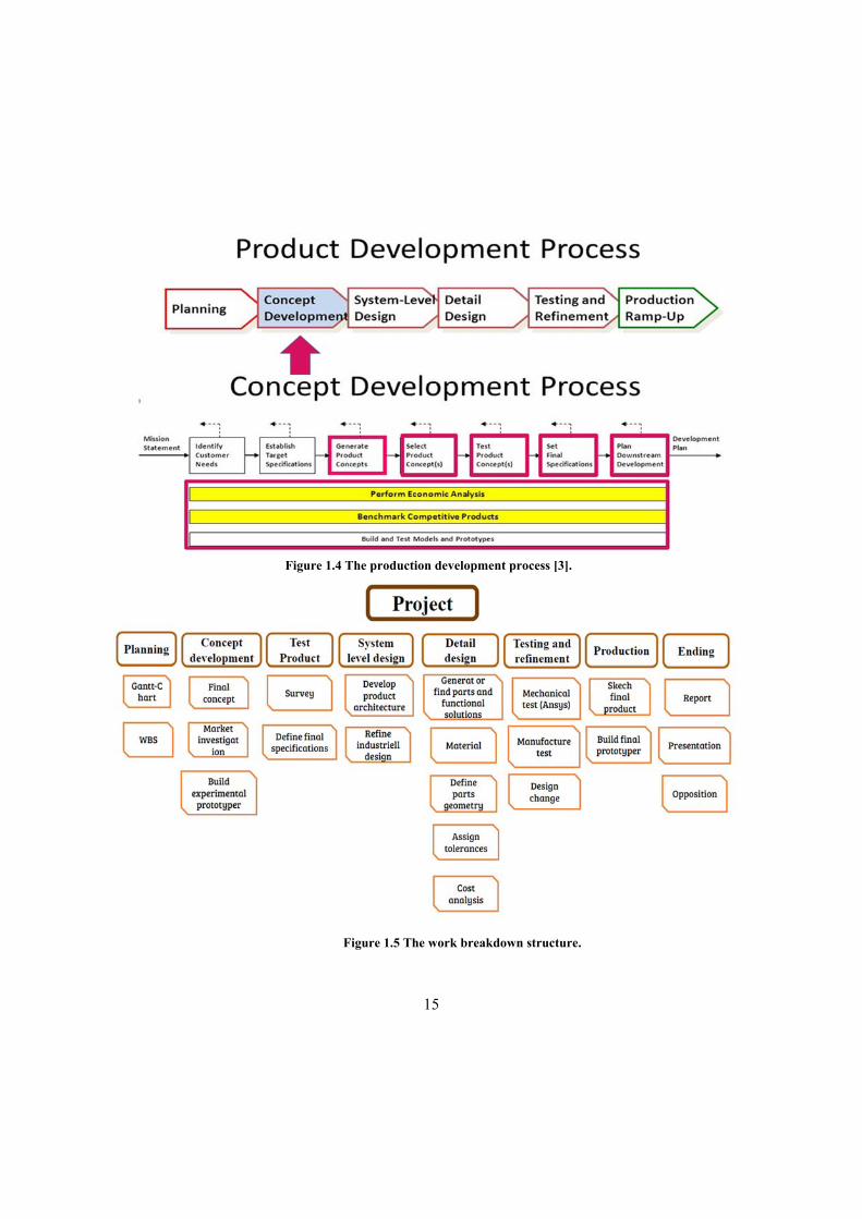
The overall development phases are based on Product Design and Development by Ulrich and Eppinge [3]. As the concept idea has determined, the accrual process focus on second half part of the concept development process, which includes even the system-level design phases, detailed design, testing and refinement in figure 1.4, where red marked. A detail of the development steps is displayed in a work breakdown structure, WPS see figure 1.5, which is a deliverable-oriented breakdown of a project into more detailed smaller components. It shows also more activities involved in construction and manufacturing steps, which are the focus areas in the thesis.
1.6.2 Project plan
A project plan was made before the project started, a Gantt chart and a WPS, Work breakdown structure [4]. The Gantt chart shows when each activity begins and ends, how long each activity is scheduled to last and where activities overlap with other activities, even the actual performed time of the activity is presented. In this way made it easily to get an overview and control over the time and resource allocation of the project. The project was planned to be finished in mid-September; however, many activities took longer time than the accrual plan. The detail of project activity is presented in the Gantt chart in Appendix A.
15
Figure 1.4 The production development process [3].
Figure 1.5 The work breakdown structure.

16
1.7 Structure of the thesis
Ch.1 Introduction
Background of the project, aims, user and method.
Ch.2 Prestudy
Patent search - to research similar products.
Market investigation - to research similar products and the need of the
market.
Dimension research of drawers for both kitchen manufacture and end users.
Build the first experimental prototype.
Ch.3 Test experimental prototype
Collect feedbacks from end user.
Collect the experimental results.
Interpret the results and define the final specifications.
Ch.4 System level design
Define and functional elements and their relationship.
First hand sketch different elements of the SMO.
Choose the industrial design of every parts of the SMO.
Ch.5 Detail design
Research and generate solutions of fixation and edge assembly.
Ch.6 Material selection
Establishing must and want requirements.
Research and comparing potential materials

17
Ch.7 Define part geometry
Testing and define final fixations solution.
Research and calculate snap fit parameters.
Introduce the first cad-sketch parts of the SMO.
Ch.8 Testing and refinement
Mechanical testing of several assembly parts by using FEM program
ANSYS and indicate changes.
Introduce use of moulding process, design rules and tolerances.
Present mould analysis and gain parameters for cost analysis.
Calculate the cost of manufacture and sale price of every parts.
Ch. 9 Production
Present final production
Build new prototyper
Ch. 10 Conclusion and discussion
Improvements and recommendations.
Further work

18
2 Prestudy
This chapter contains basic insight to get better understanding the project and the potential of the market. It included patents search and a market investigation of several big kitchen manufactures.
2.1 Patents search
A patent search has conducted in patent databases available to check the inventions already exists, but also gains new ideas and solutions for the concept generating. There are many patents search tools available in the web. In this thesis used mainly three databases which recommended by Olaf Diegel [5]. Those will be able to cover for the use of the thesis.
European Patent Office
U.S. Patent Office
Google Patents
2.1.1 Conclusion of the patents search
Under patents search process some similar idea was found but with different using area, design and partition solutions. After search with keyword: drawers, pegboard, kitchen. A of patents named Selectively configurable household accessory holder, which capable of being customized through adding and removing a variety of containers to a base. See figure 2.1, left. It has similar functionaries as the SMO but serves with different purposes. Another relevant patent named Expandable drawer organizer after search keyword: drawers, slidable, organizer. The organizer utilizes one or several trays maintained in slidable agreement with another a tray, providing for the expandable drawer organizer to be varied to approximate the dimensional constraints of the subject drawer see figure. 2.1, right.
The results of the patent search revealed that patents of similar applications are not existing and did not cause a threat for the legal rights of the product development

19
2.2 Market investigation
2.2.1 Modern kitchen manufacture
After many failures of trying to contact kitchen manufactures which use pegboard solutions as their interior organizer, a further investigation has been conducted. Searching some of biggest kitchen manufacturer in Sweden to get information about the similar products, dimension of the modern kitchens and the existed organizer solutions. The stores that were visited were in following:
● IKEA, Kulthusgatan 1, 215 86 Malmö
● HTH kök, Avtalsvägen 3, 227 61 Lund
● Elgianten, Avtalsvägen 3, 227 61 Lund
● Kvik, Företagsvägen 36, 227 61 Lund
Figure 2.1 Selectively configurable household accessory holder [6] at the left, Expandable drawer
organizer [7] at the right.

20
IKEA is the one of the leading furniture manufacture in world. It takes business actions to boost profits by offering smart and affordable home furnishing products, which gains customers in different society level [8]. In Sweden, IKEA is one of most popular place of purchasing kitchenware for students and low-income group. They are thousands of products which provides one stop shopping. The ideology of the IKEA products is very similar for idea of self-modeling organizer. Therefore, IKEA is chosen to be my first place for the investigation. IKEA offers many other smart solutions for helping fit inside drawers and cabinets to give everyone an organized home. All the solutions keeping in a series of productions named VARIERA [9]. One of the product named MAXIERA. See figure 2.2, which design to adjust storage area depends on the need.
Several kitchen manufacturers in Lund have also been visited during the data collection to find more information about the organize solutions. All the personal in the kitchen retailer are friendly and helpful. They showed me the solutions they offer and the categories magazine, which contains all the detail about the price and size of their kitchen organizer. All the kitchen retailer offers solutions for inner organizer for drawers, which are compatible with their kitchen. The stores are allowing private purchasing for the inner organizer but, it is unusual, according to the personal in the retailers.
The interior organizer solution used in the other three kitchen stores are shown in figure 2.3. They offer very similar solutions. The solution uses long walls, which have same length as drawers to partition area. The fixation is on the both side of the drawer and the differences between them are Elgiganten use pegged attachment on the drawer’s side. HTH and Kvik use slidable cylinder or rectangular pathway. The material of the walls used is often ABS plastic.
Figure 2.2 MAXIERA [8] from IKEA

21
The cutlery holder used to hold the knife, fork and other small items. The solution of the cutlery uses mainly one size solution which means the manufactures have pre-decided the size. The material used is often ABS plastic or wood see figure 2.4 below.
Elgigantan not only offer a one size type but also a partly adjustable solution for cutlery holder see figure 2.5. The holder offers standard set which can be purchased separately. There are three sizes of box choose between depend on the need of customer. The set is mainly made by steel and very pricey.
Figure 2.4 One size cutlery holder solutions [12]
Figure 2.3 shown the pegged side [10] used by Elgiganten and slidable side by HTH, Kvik.

22
2.2.2 Conclusion of market investigation
By comparing those solutions, there are all very practical and easy to use. However, the solution for interior organise are only accommodate for their drawer’s figure and size. It can’t integral with another kitchen storage. From the results of the market investigation, the market for selling the SMO consider good due to its peculiarity and few competitors.
2.3 The dimension of base drawer
To be able to design and define the SMO, it is important it can fit not only in old kitchen but also modern kitchen drawer so that the product will continue sever their purpose even the old kitchen has changed. In this paragraph contains the collection of the dimension data of the drawers from the end user, kitchen manufacture and some theoretic rules.
Most of kitchen manufacture offer pre-order and personally planning for meet customer’s kitchen requirement, which often more expensive. In another hand, kitchen manufacture has so called standard kitchen, are available from the store shelf with no special-order requirements, and the sizes are very basic to satisfied low budget customer’s needs. Those are often first choice for used in rental accommodator, which confirmed by Linda who work as property assistant in Lunds Kommuns Fastighets AB and by Patrik Norgren, house overman in Stiftelsen Michael Hansens Kollegium, One of student rental agency in Lund.
Figure 2.5 The adjustable organizer [13]

23
2.3.1 Kitchen manufactures
In this section, the dimensions of the drawers from the four kitchen manufactures has been collected and shown in table 2.1. Under the collection focused on two type drawers. Base drawer is often quite short and it used to keep the cutlery or species. High base drawer can be different height and used to store all kind of kitchen items. see figure 2.6, left. As the manufactures have different way naming the dimensions of the drawers, a general name system used here shown in see figure 2.6, right.
Table 2.1 Base drawer dimensions from the kitchen manufactures.
Name Brand Width [cm] Deepth[cm] Height [cm]
Base drawer (height)
IKEA 40, 60, 80 56.4 Up to 80
HTH 36.5, 46.5, 56.5 56.5 Up to 80
Elgigantan 30,40,50,60,80,120 52.3 Up to 80
Kivik 30,40,50,60,80,100,120 56 Up to 80
Base drawer
(low, cutlery holder)
IKEA 40, 60, 80 56.4 7.8
HTH- 36.5, 46.5, 56.5 56.5 8.5
Elgigantan 30,40,50,60,80,120 52.3 8
Kivik 30,40,50,60,80,100,120 56 8.2
Figure 2.6 The base drawer and the naming system [14]
24
2.3.2 Student apartments and private rental company
As the product is designed to sell low budget groups, it is important to understand how their kitchen condition are. To obtain that information from customers, several visits to student apartments and local council rental apartments in Lund were performed. Under the interview, the organising behaviour of the interviewee and the dimension of the drawers and cabinet have observed and noted.
The following persons have participle the interview for data collections. The interview template can be found in Appendix B. The data shown in appendix b were only four interviewee, which represented and covered all the important informations.
Delphi, one room apartment Kämnärsvägen 20A, Haoming Wang
Parentesen, corridor room with collective kitchen,Södra Esplanaden 32,
Erik wollter
Vildanden,one room apartment,Ällingavägen 9B, Herninanjati
Paramawardhani
Stiftelsen Michael Hansens Kollegium,two room and kitchenette, Dag
Hammarskjölds väg 4A,Hannes Carlson
Sparta, corridor room with collective kitchen, Tunavägen 39, Yuwei Xiao
LKF, two room with kitchen,Stiftsvägen 12 , Cecilia Fröberg
Private company, Three room and kitchen,Svangatan 20A, Mikael Rudner

25
Figure 2.7 The base drawers in student apartment in MHK and Delphi
The visit of several student apartments has revealed, many kitchens have short width of drawers see figure 2.7 above. Most of them have the width shorter than 35 cm.
2.4 The first experimental prototypes
To be able to get more feedback and improvement from user, the first experimental prototype was built see figure 2.8. As many details have not been defined, the prototype was built only using the experience from the original concept and designer knowledge. The experimental prototype is consisting of three parts. The bottom plate, dowels and walls. The bottom plate is built by using laser cutter and the dowel use a standard treenail in JULA and chopsticks. To test different length of the dowel, some treenail has glued together and cut it to desirable length. The wall used a black foamed board with tree dowel as fixture solutions. The detail of the experimental prototype is shown in table 2.2.

26
Table 2.2 Dimensions of the first experimental prototype.
Item name Dimension [mm]
Pegboard 260 *200 *4
Distance between holes 15
Treenail 6*30
Wall 1 200*50*8
Wall 2 60*50*8
The length of tree nail 30,60,90
Figure 2.8 the first experimental prototype.

27
3 Concept testing
This chapter starts the process of testing the experimental concept and get feedback from end user, then define the final specifications of the SMO.
As the original concept is easier and cheap to build, it is wise to test the concept for real with responses from potential customers in the target market. The testing is helping to get information from customers for improvement of the concept and design idea. We can break down the testing process into 7 steps.
1) Define the purpose of the concept test 2) Choose a survey population 3) Choose a survey format 4) Communicate the concept 5) Measure customer response 6) Interpret the results 7) Reflect on the results and the process
3.1 Define the purpose of the concept test
The first step of the concept test is to define what kind of information need to be collected? Is all the information from customers reliable? What question should be asked?
As those questions are crucial for the result of the concept test even for future refinement of the concept, it is important to searching some approaches around this. The approach of Anthony Ulwick named outcome-driven approach point out today's the drawback of the customer driven approach mentioned in a citation in the book what customers want?[15].
‘I have discovered one factor that stands out above all others in derailing the customer-driven approach and in introducing process variability. Ironically, it is the inputs that come from the customer— that’s right, the customer’s requirements. When companies gather customer requirements they do not know what types of inputs they need to obtain from the customer. Neither does the customer.
28
The right customer inputs are one major factor to success, therefore the questions of the survey made based on the outcome driven approach, which means it focus on in following areas.
Which jobs their customers are trying to get done?
1. How well the self-modeling organizer helping you organize staffs in kitchen?
What are the outcomes customers are trying to achieve? And what are the outcomes that are unwanted?
1. How well the SMO helping to organize the plates or lunch boxes?
2. How well the SMO helping to organize the cutlery?
3. How easy is it modeling the SMO?
4. How good is the fixture solution of the SMO?
5. The size of the SMO.
6. Other dissatisfactions.
What are the constraints that may prevent customers from adopting or using a new product or service?
1. The SMO must fit most of the drawers.
2. The SMO must be easy to model.
3.2 Choose a survey population
The product targets consumers that do not have a permanent living situation such as students or people moving to big city while seeking job and even for them who interested in keeping things well organized. Most of them are quite young, seeking often a product with low price. The interviews were conducted using 20 different persons. The background of the persons from the interviews is following:

29
Figure 3.1 The age, gender, living type and family number distribution of the interviewee.
3.3 Choose a survey format
This thesis used two common methods to collect the information, face to face interview and observation. Observation requires precise analysis by the researcher and often produces most accurate results although it is very time consuming. Interviewing is easier but suffers from the fact that participants may not come up with honest replies [16]. By integrating both methods can gain information by different perspective. During the interview, an audio recorder was used to avoid missing important data.
The interview and observation took place in the same time. It starts the interviewee showing around their kitchens, where the cookware, plate, cups storage. What the problem they have. The dimension of drawers and cabinet have been collected.

30
3.3 Communicate the concept
The experimental prototype was brought in place where the interview took place. The interviewee was asked to modeling organizer for their own needs. Some of the ideas of modeling were showed for the interviewee.
3.4 Measure customer response
The survey participants were asked to give degree of satisfaction for how the SMO performed, by using a scale of 1 to 5, where 5 means totally satisfied and 1 means not satisfied at all.
3.5 Interpret the results
The purposes of this step are slightly different from Karl T.Ulrich approach, where the focus is comparison and understanding concepts from various perspective. For instant, cost of manufacturing or estimating the future demand. As the design and features of the concept idea were not defined yet, interpreted the feedbacks of the interviews and observation was made. The interpretation could be useful to definition of the final specifications and the industrial design.
3.5.1 The results of the testing
The experimental prototype was put into real test, carry plates, organize cutlery and lunch boxes see figure.3.2 and 3.3. At the same time note the performance of the prototype to discover improvements areas.

31
There are many issue and underperformance have appeared during the test. According to Karl, the expression of the interviewee about of testing the prototype in previous step must interpret to more specifically and positive terms to avoid translate the collected data into different requirements. Some of the expressions are overlapping and therefore the answers were merged. The interpretation shown in table.3.1.
Figure 3.3 Testing of the first experimental prototype in the drawers and bearing the plates.
Figure 3.2 Organizing the lunch boxes by using the prototype.

32
Table 3.1 Interpretation of the customer statements.
No Customers and test statements Interpretation to needs
1 It is difficult to put the dowels into holes and it feels not stable.
The fixture solution must be easily to install and stable.
2 The holes do not look so nice. The fixture has a good appearance.
3 The distance of the holes is too little. The holes’ distances are too short.
4 The product is too small The size has to increase.
5 How to put pieces together The SMO has an assembly solutions
6 The height of wall is too short if I want to use to create area for organise staffs.
Solution for general organisation.
7 There is gap between the walls. It has to avoid gaps between the walls connections.
8 It takes too long time to modelling The modelling time must decrease.
9 It should not be expensive The price must be low.
10 The bottom is not stable in the drawers It has to be fastening on the drawer or cabinet bottom.
11 It should not be easily damaged It must be tough, anti-scratch
12 It can carry plate for vertically and horizontally
The dowels have to be stiff.
13 I can clean it with water. It must be water resist.

33
3.6 The final specifications
After the interview and the observation of the prototype, the final specifications table 3.2 can be established. However, many of the specifications were hard to provide a metric value duo to the product architecture and some solutions has not finally determined. Therefore, it is given a subjective metric.
Table 3.2 The final specifications
No. Metric Unit Target value
1 Dimension mm Maximal breadth is 350 mm
2 Toughness Shore D -
3 Tensile strength MPa -
4 Maximal temperatur °C 80
5 Friction and wearing properties
Sjub
6 Stiffness MPa -
7 Stress and cracking concentration
- Sjub
8 Adhesion - Sjub
9 Weight kg Less than 1,5
10 Moisture resist Yes/No Yes
11 Easy to use Subj Yes
12 Environment friendly Yes/No Yes
13 Pris SEK Less than 60

34
4 System level design
This chapter presented the functions and functional relationships between the components of the SMO. The initial industrial design of each components will also be shown.
4.1 Develop product architecture
In informal terms, the architecture of the product is the scheme by which the function of the product is allocated to physical components. Ulrich and Eppinger define product architecture more precisely as [17]:
The arrangement of functional elements; The mapping from functional elements to physical components; The specification of the interfaces among interacting physical
components.
4.1.1 The arrangement of functional elements
The functional requirements of the SMO is displayed and expressed as linguistic terms like 'convert energy', connected by links indicating the exchange of signals, materials, forces and energy see figure 4.1 The functional requirements can be abbreviated for short.
Partition areas - requires that can create and rearrange the area for different organizer purposes
Immobilize - requires that it can keep the items in the desired places.
Provide support - requires that it gives supports for the items and keep it in certain desired position.
Fixation - requires both for the partition tools like dowels, walls need be strongly fastening on the bottom plank and the bottom plank needs to be stabilized on the drawer’s bottom.
Assembly - requires for partition tools can be easily installed and taken apart from the bottom plank. Even for assembly between the bottom planks.

35
Figure 4.1 The arrangement of functional elements
The functional elements in the left side, fixation and assembly need to apply before the functional elements at the right.
4.1.2 Mapping from functional elements to physical components
For clarity, a component defined as a separable physical part. However, a physical component can implement one many functions of the production at the same time. The mapping see figure 4.2 between functional elements and components may be one to-one, many-to-one, or one-to-many.
Both the dowel and wall can provide functions as partition, immobility, support, which need to be contacted with the bottom plank by fixation solution. The assembly occur only between the bottom planks.

36
Figure 4.2 Mapping from functional elements to physical components.
4.1.3 Determine the interfaces among interacting physical components
As it shows if the dimension of the dowel changes, the bottom plank must change to a response dimension to get the dowel fastened. This phenomenon called the coupled interface. The coupled interface of the component was shown by line in figure 4.3.

37
Figure 4.3 The interfaces among interacting physical components.
4.2 Refine industrial design
Industrial design is one of the key factors that attracts customers to buy a product, or leads them to prefer using one product over another. By search inspirations in the internet and literature about the aesthetic need. The initial design sketch of the concepts of each component started forming. There are five goals according to Ulrich and Eppinger should the designer helping the product to achieve: Utility, Appearance, ease of maintenance, low costs and communication. As those goals are often interrupt with each other, somethings a tradeoff need to be considered depend on the situation. After the brainstorming, the sketches presented below.
4.2.1 The walls
Design 1
The original design used walls as partition tool, but it has changed to a complete piece with three walls with fixation solution under the walls. By combination two pieces with or no with gap in between, a single cutlery holder is created. As it designs to keeping cutlery or small long items, this cutlery holder can adjust the length by adjusting length of the gap. One of reasons of the design changes is consideration of reducing the installation time. The cutlery holder can have presented in figure 4.4

38
Figure 4.4 The first concept of the cutlery holder.
Design 2
Design 2 inherited the wall concept from the original prototype and developed to some new features, a adjustable middle wall to partition area for the horizontal direction with the vertical support of the walls see figure 4.5. Both the walls and the middle wall can be removed from the bottom plank. The middle wall is assembly directly to the wall by the ruts.
Figure 4.5 The second concept of the cutlery holder

39
Chosen of the designs
There are advantages and disadvantages in both designs, but the design 2 are more superior in many areas than design 1. Firstly, efficiency of partition area. It partitions the entire area and create many organize units in both directions by adjusting the distances between the walls instead of only single organize unit. Secondly, the long wall design easier made and cheaper to package with other components and less transportation area. Finally, the design 2 has a higher usage of the material for its functionalities than the design 1 when it creates several organize unit. The most cases, the customers want to store different types of cutleries separately. The side wall of the design 2 creates a lot overlapping area when it creates more than one organizes units.
4.2.2 The bottom plank
To increase the aesthetic of the product and make it more attractive looking, the bottom plank changed design to use track to lock the fixation solutions of the partition applications instead of using the pegboard. There are end lock to both side of the tracks see figure 4.6. The merit of the track design is it gives more freedom to move in the vertical direction instead of the limitation of the hole’s position. To be able to minimize the use of material and make it easier to cut to fit the drawer, a cuboid has inserted between the tracks. The weakness of this design is the decreasing stability of the fixation solutions in vertical side.
Figure 4.6 The design concept of the bottom plank and a section view of the middle.

40
4.2.3 The dowels
The dowels are redesigned to have more supporting dowels at it sides, see figure 4.7. The reasons of the design change are to increase possibility to separate areas and to increase stability. The distance between the dowels can be used to organize plates vertically and the convex bottom design creates a supporting force to stabilize the plate’s position. The two extra dowels and convex draft stabilize the whole system from the side forces. The dowels in the middle has longer length than two others, to make it easier to be grid in ergonomic point of view, this design helps to keep the neutral posture [18] of the fingers during the installation. The appearance dowels use the original cylinder shape, has a smooth arc curve which fits to the functionally requirements.
Figure 4.7 The dowel design view at the front and at the left.

41
5 Detail design
Chapter 5 presents the process of finding and deciding the details design of the SMO, the fixation solutions and the assembly solution between the bottom planks.
5.1 Fixation solution
The lock solutions of the bottom plank for the fixture of the dowels and cutlery holder can be explained in detail as a concave- convex track of the bottom plank see figure. 5.1. The principle is to design a solution that keeps the fixture solid in this track and at the same time, it should be easily and smoothly assembly and disassembly.
Figure 5.1 The cross section of the bottom plank track

42
5.1.1 Research
Curtain track
One of the usual example of holding a carry in a track is curtain track see figure.5.2. There are normally a track and many carries (The wheel) move back and forth within the track. The advantages of this solutions are it is strongly securing the track and it is easily to move the dowels. However, it fastens inside the track and cannot be removed until the end stops of the track. Furthermore, it will need end stops for both track direction for secure slipping out, which may increase the manufacture cost.
Figure 5.2 The curtain track
Snap rivet and lock pin
Snap rivet and lock pin are simplest, quickest and most cost-effective method of assembling two parts, which used widely in industrial. They are normally made by thermoplastic. There are hundreds of types with different purposes and lengths.
Figure 5.3 Snap rivet

43
The most popular of any type of rivet is the one is easiest to install see figure 5.3. By simply pushing the head in, the grommet expands to lock into a secure place. Removing is also easy by pulling on the head to release it [19]. The drawback of this solution is the difficulty to implement the head into the track.
The lock pins
Lock pin uses the spring characteristic of the thermoplastic to shrink and expand the hook part into a head. There are various designs depend on the use area see figure.5.4.
Figure 5.4 Design examples of the lock pins

44
5.1.2 Concepts for fixation solution
Combine the research solutions, a series of fixation concepts has been developed to stabilize the organise applications into the bottom plank. There will only present the design of the solutions, more detail will reveal gradually through the developing process.
Concept 1
Concept 1 fixation use a two floors ellipse shape with different size in the top and in the bottom. The small size of the ellipse made easily to slide vertically into the tracks see figure 5.5. When it turns 180 degrees, the ellipse lock into the track. The top ellipse creates large fixation area so that the dowel can be keep stabilized in both directions. The drawback of this solution is can’t be used in fasten the wall into the track.
Figure 5.5 The fixation concept slides into the track.

45
Concept 2
The idea of the concept 2 is like the snap lock pin, where instead of using four support pins to lock the cylinder dowel into the track. The cross section of the pins is chosen to be square to providing maximal grip area and avoiding gaps. The head of the pins are squared with draft see figure 5.6.
Figure 5.6 The concept 2 in and out of the track.
Concept 3
The concept 3 is based on a further development of the concept 2. By using two wider support pins. The advantage of this concept is it has better grip and can withstand more stress but it uses more material than concept 2 see figure 5.7.
Figure 5.7 The concept 3 in and out of the track
46
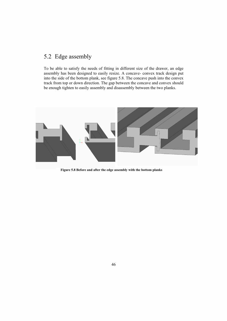
5.2 Edge assembly
To be able to satisfy the needs of fitting in different size of the drawer, an edge assembly has been designed to easily resize. A concave- convex track design put into the side of the bottom plank, see figure 5.8. The concave push into the convex track from top or down direction. The gap between the concave and convex should be enough tighten to easily assembly and disassembly between the two planks.
Figure 5.8 Before and after the edge assembly with the bottom planks

47
6 Material selection
In this chapter presents the material selection process for the SMO. It describes the definition of the material, the requirements and further valuation of several candidates to choose a material meeting the product requirements.
Material selection is a step in the process of designing of any physical object. In the context of product design, the main goal of material selection is to minimize cost while meeting product performance goals. Systematic selection of the best material for a given application begins with analysing the properties and costs of candidate materials. As the primary user groups are low income, the price of the product need to be reasonable and suitable to apply different features. Thermoplastic is known as a material with high form flexibilities and low price. The material selection process follows User’s guide to plastic by Bruder [20].
6.1 Establishing the requirement specifications
To establish a complete requirement specification, we need to take many considerations in mind such the market-, functionality-, environmental- and manufacturing-requirements. However, not all the requirements have the same importance and there are often needs of some trade-offs between them. The requirements can be mainly divided into two categories, the MUST requirements and WANT requirements.
6.1.1 MUST requirements
The must requirements are the ones with the highest priority and it must be fulfilled before releasing the product into production.
● Excellent mechanical (stiffness strength, stress, creep and fatigue) properties in a range of temperature between 15 to 80 °C.
● Scratch resistent
● Food grade approved
● Low material and manufacture cost

48
● Excellent friction and wear properties
● Spring properties
6.1.2 Want requirements
In the other hand, the want requirements have a lower priority and it will be pleasant to have those features but it is not necessary.
● Solvent resistance
● Easy to colour and to paint
● Not absorb moisture
● Self extinguishing
● Environmental friendly
6.2 Specify and sort the material candidates
After the MUST and WANT requirements to have been set up, several plastic material candidates have been sorted out. The information of the material properties obtained in some of the official polymer databases, Omnexus [21], Matweb and Campus polymer. The properties filtrate after the requirements, like the price and required mechanical properties. An additional material information about the properties ranking of designing snap fits from BASF can be found in table 6.1 and figure 6.1.
The coefficient of friction and wear - contributes to how easy or difficult it is to assemble or disassemble a given joint design. The SMO has many tracks design, which requires the surfaces that the plastic slide smoothly against each other. The coefficient of friction can be improved by adding lubricant or fluoropolymer. The incompressible lubricant fills the gaps between the asperities and acts as a fluid bearing surface to allow smoother movement of the two materials.
Tensile, stiffness strength and hardness - affects the product will either break or undergo permanent deformation, how well it withstands impact, surface scratch and elongation. The SMO is designed to organise cookware, plates and cutlery etc. The dowels and the bottom plank need to withstand at least equine to 8 ceramics plates’ weight (high secure factor). One plate weighs around 0.64 kg. The plates will totally produce estimated 0, 192 MPa stress to a circular ring area as the bottom support of a plate with diameter 28 cm, which estimated around 20,8 cm2. The detailed calculation can be founded in Appendix C. Most of the plastic reinforced stress and stiffness ability by adding different fibre, the most common and cheapest being glass fibre.

49
Modulus of Elasticity - Modulus affects the degree of stiffness or rigidity and determines firmness of the assembly. The SMO demands assembly conform to tighter tolerances, which requires a material with higher modulus and greater stiffness. In applications with more dynamic and repetitive demands, lower modulus could potentially result in more noise (or BSR: buzz, squeak and rattle) from loose joints. The tightness of an assembly with a higher modulus material also helps establish the “feel” of a product, in some cases contributing to a tangible sense of quality[22].
Fatigue Strength - the ability of a material to withstand a given level of repetitive loading (or cyclic stress) until the point of failure from fatigue – number of cycles until breaking.
Creep Behaviour and Stress Relaxation - creep behaviour describes plastic components exposed to a constant stress or load will be deformed over time. The relaxation means a plastic component is subjected to a constant deformation, over time stresses will emerge and decrease to a stress- free state [24].
Table 6.1 Comparing the properties of the materials candidates
Name
Min temp
Max temp
Food approved
Modul min [MPa]
Modul max [MPa]
Hardness [J/m]
Stiff.
[GPa]
Price [sek/kg]
PA 6 -20 80 Yes 800 2000 50 2 24
PA 66 -65 80 Yes 1000 3500 50 3 35
PE -30 67 Yes 300 600 999 1.5 15
PET G -40 63 Yes 2800 3500 10 3.5 22.5
PP -10 100 Yes 1100 1600 20 1.6 15
POM homo
-40 80 Yes 2800 3700 60 3.7 26
PPE -40 80 No 2100 2800 130 2.8 20
ABS -25 86 No 1790 3200 200 2.4 23
PVC plasticized filled
-5 50 No 10 1800 20 1.8 20

50
Figure 6.1 Material properties performance comparing of BASF [23]

51
6.3 Further valuation of the material candidates
After some considerations and comparing how well the materials meet the MUST and WANT requirements, four potential materials stand out into the final valuation. Obviously, it is impossible in the scope of this paragraph to provide a comprehensive analysis of all the material candidates, because there are so many different qualities and brand. With limitation of available properties database, can only introduce representative grades from the major resin families and provide a rough, rule-of-thumb rating of relative performance. As the table 6.2 revealed Polyoxymethylene (POM) have fulfilled with the most requirements. It will be used as the material for the SMO.
Table 6.2 Comparing material candidates.
Requirements
Weight
factor
PE-UHMW
(GUR 2122)
(Reference)
PET
(Rynite®530 NC010)
PP
(POLYFORT® AFP 2934)
POM
(ALCOM POM 770/1.1 CF10
Load and impact resistance
0,15 3 0,45 5 0,75 3 0,45 4 0,6
Surface scratch 0,15 3 0,45 3 0,45 3 0,45 4 0,6
Friction and wear 0,15 3 0,45 2 0,3 2 0,3 4 0,6
Stiffness 0,1 3 0,3 4 0,4 3 0,3 5 0,5
Creep or fatigue 0,1 3 0,3 4 0,4 3 0,3 3 0,3
Color 0,075 3 0,225 4 0,3 3 0,225 3 0,225
Environmental friendly
0,075 3 0,225 3 0,225 3 0,225 2 0,15
Price* 0,2 3 0,6 2 0,4 3 0,6 2 0,4
Rank 3 3,225 2,85 3,375
Material chosen No No No Yes
*The price is only material cost.
52
7 Define Parts geometry
Chapter 7 presents the process of how the final parts geometry and detailed solutions like snap fits, fixations defined by using finite element method (FEM) based simulation program Ansys.
7.1 Final fixation solution
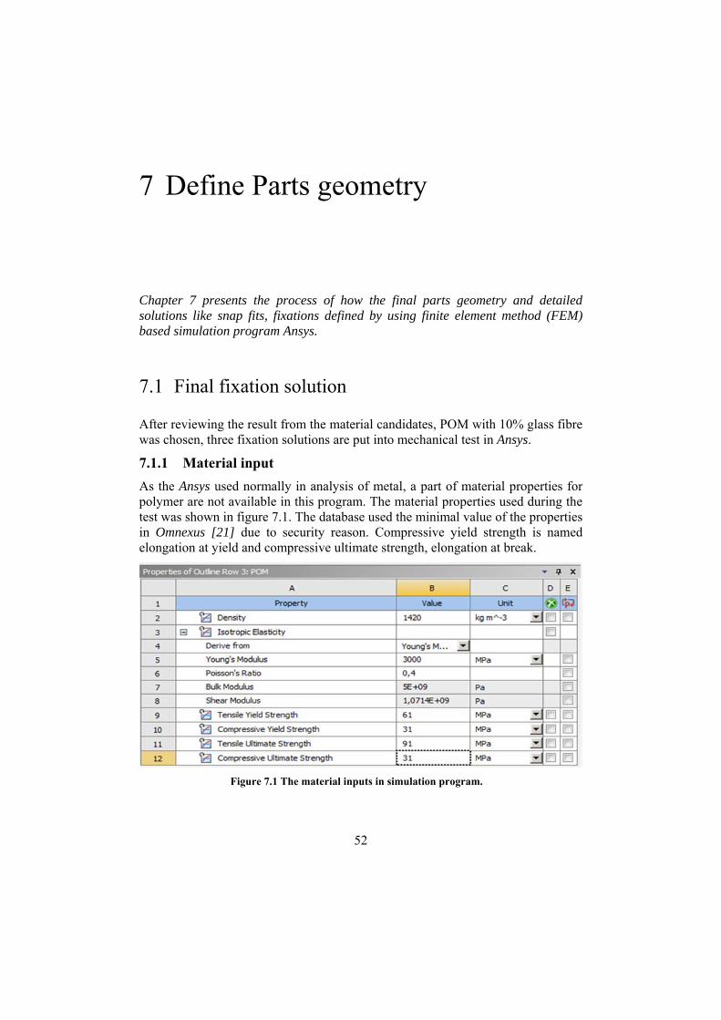
After reviewing the result from the material candidates, POM with 10% glass fibre was chosen, three fixation solutions are put into mechanical test in Ansys.
7.1.1 Material input
As the Ansys used normally in analysis of metal, a part of material properties for polymer are not available in this program. The material properties used during the test was shown in figure 7.1. The database used the minimal value of the properties in Omnexus [21] due to security reason. Compressive yield strength is named elongation at yield and compressive ultimate strength, elongation at break.
Figure 7.1 The material inputs in simulation program.

53
7.1.2 Part’s geometry changes for testing
The purpose of this paragraph is to find the most suitable fixation solution, to minimise the simulation time, only the important parts have taken into the simulation. As the simulation program is limited for where the force can be applied, a little area of 1 mm2 convex was sketched in the both testing surface 35 mm from the dowel bottom, where the testing force will apply see figure 7.2 left. The testing diameter of the dowel is 6 mm and the test length of the dowel is 40 mm. The testing bottom plank part use a single track with a length of 20 mm see figure 7.2 right. All the three fixation concepts were tested in the same condition.
Figure 7.2 The testing-adopted bottom plank.
7.1.3 Contact strain and mesh setting
The contact strain between the fixation solution and the track define as friction contact with a coefficient 0.2 [27]. In finite element method, the quality of the mesh has great impact on how accurate the analysis results are. The finer mesh is, the more accurate results but, the finer mesh causes longer simulation time. The overall mesh size was defined to be 1 mm. The contact areas in the track and surfaces contact between the dowel and the bottom plank are more interested and therefore, a finer mesh with edge size 0, 5 mm applied in those areas in all the three fixation concepts see figure 7.3 and 7.4.

54
Figure 7.3 shows where the contact surface applied and the friction coefficient.
Figure 7.4 Contact areas applied with finer mesh in left and a test-adapted pathway in right.

55
7.1.4 Testing environment
The purpose of the testing environment is to compare the three-fixation concept’s ability to withstand mechanical loads. Therefore, the effect of thermal loads and vibration will be negligible. The testing condition designed to corresponds to a real user situation, which exposed to force in different directions. In this case, we chose to simulate the two most frequent case, the vertical and horizontal direction see figure 7.5. To have the same moment, the force applied in 35 mm distance from the dowel bottom. The magnitude of the force totalling the weight of eight 28 cm plates pulling out from a drawer with an acceleration 0,5 m/s. The acceleration assumed quite strong to secure the safety and quality of the dowel. The detail calculation of the force can be found in Appendix C. The test conditions are following.
● Force_1 2, 56 N in a small surface of 1 mm 2 Z-axel of the dowel see fig-ure 7.5 left.
● Force_2 2, 56 N in a small surface of 1 mm 2 X-axel of the dowel see fig-ure 7.5 right.s
● Fixed support in the bottom of the plank.
Figure 7.5 The pressure applied long x-direction and z-direction of surface of the concept 1.

56
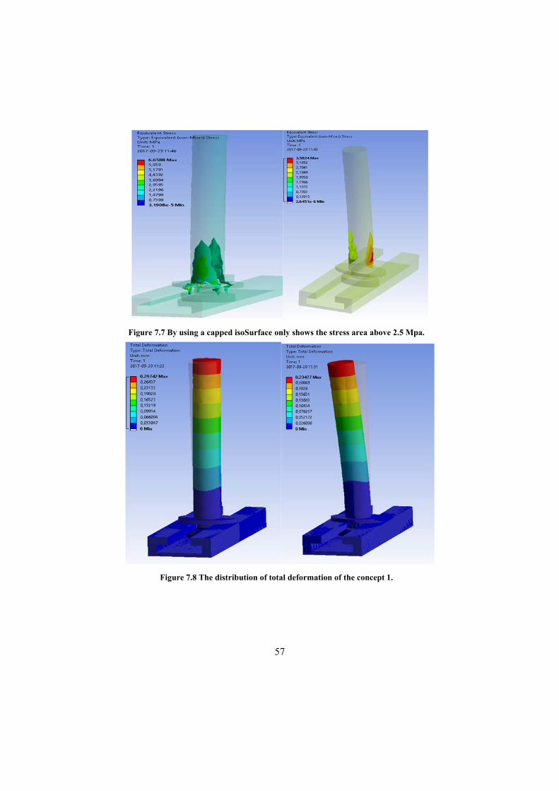
7.1.5 Results of simulation
The magnitude and areas of stress concentration and total deformation of the three fixation concepts shown in Figure 7.6 – 7.13. The first two concepts shown also capped isosurface figures about the stress, which can display the stress area above or under certain value to be able to explore areas hided by other components. The table 7.1 summarizes the results of the simulation. It shows there are no larges differences between the concepts when it withstands the loads.
Table 7.1 Simulation results of the three fixation concepts.
Properties Concept 1 Concept 2 Concept 3
Force _1 Force_2 Force _1 Force_2 Force _1 Force_2
Total deformation [mm]
0,29
0,23
0,34
0,29
0,25
0,25
Maximal stress [MPa]
6,6588 3,59 8,6138 4,87 3,85 4,14
Factor of the safety
9,16 Above 15 7,08 12,504 15 14,73
Figure 7.6 The stress distribution for concept 1.
57
Figure 7.7 By using a capped isoSurface only shows the stress area above 2.5 Mpa.
Figure 7.8 The distribution of total deformation of the concept 1.

58
Figure 7.9 The stress distribution for concept 2
Figure 7.10 The distribution of total deformation of the concept 2

59
Figure 7.11 The stress concentration areas above 4 MPa in concept 2.
Figure 7.12 The stress distribution for concept 3

60
Figure 7.13 The distribution of total deformation of the concept 3
7.1.6 Define final fixation solutions
To define the final fixation needs a holistic consideration of performances of many perspectives. The table 7.2 listed some of the most important requirements and how well the three-fixation solution performed in those areas. To assess how easy the fixation solutions are being installed or removed based on the ergonomic principle of keep the natural position of the hand [18] and how much force need to install and remove. The performance of stability valuated base on the results of simulation model. Flexibility means how easy the solution can be integrating or used in other partition applications without encountering complexity. The results of the table 7.2 shown the concept 2 is the best candidate and therefore chosen to be the final fixation solution.

61
Table 7.2 Comparing the three fixation concepts.
Requirements
Weight
factor
Concept 1
(Reference)
Concept 2 Concept 3
Easily install and remove 0,2 3 0,6 2 0,4 2 0,4
Install and remove in both directions
0,3 3 0,9 5 1,5 3 0,9
Stability 0,2 3 0,6 2 0,4 5 1
Flexibility * 0,3 3 0,9 4 1,2 3 0,9
Rank 3 3,5 3,2
Chosen No Yes No
*Flexibility means its ability to be integrated with other solutions.
7.2 Design challenges of straight beam cantilever snap fit
As the previous step has determined use snap fit as joints between the track and partition applications. A straight beam cantilever with simple cantilever snaps of rectangular [24] with incorporating a 90° return angle seen to be a good choose see figure 7.14. A wider return angel will make it easy for the action of removing, but it effects the stability, which a more critical for the SMO, furthermore, the 90-return angel minimize the effects of creep and stress relaxation [25], which increase the sever time of the product. One of the most common cause of failure in snap-fits is stress concentration due to a sharp corner between the snap-fit beam and the wall to which it is attached. Since this location normally coincides with the point of maximum stress, a sharp corner can increase the stress beyond the strength of the material, causing point yielding or breakage. See figure. 7.15 graphically represents the effect the root radius has on stress concentration. One solution to deal with the sharp corn is to incorporate a fillet radius at the juncture between the beam and the wall, so that the ratio of radius to wall thickness (R/t) is at least 50%.

62
Figure 7.14 Snap fit with 90 degrees return-
Figure 7.15 Effects of a fillet radius on stress concentration.

63
The parameters need for the calculation of the snap fit illustrated in figure7.16
Figure 7.16 The Symbols of the parameters
W = Push-on Force
P = Perpendicular Force
µ = 0,2 (Coefficient of Friction)
α = Lead Angle (Assume 10 degrees)
b = 2 mm (Beam Width)
t = 2 mm (Beam Thickness)
L = 8,5 mm (Beam Length)
E = 2800 Mpa (Flexural Modulus)
∈o = 5,33 % (Allowable Material Strain Table)
Y = 1,2 mm Deflection
The calculation was made by using a Snap fit calculator [26] see figure 7.18. The parameters of the snap fit needed to use a thickness t = 1.2 mm and Ymax = 1 mm. to be able to get a strain around 5, 33 %, which estimated by using figure 7.17 to comparing the difference of the allowable strain value between the unfilled and the 30 % GF 30 % Acetal (POM) to calculate the value for Acetal (POM) GF10%, To be able to a strain below 5, 33 % requires a Length enquired to 8.5 mm, between the root and hook. A detail computation example can be found in Snap-fit Design Manual [27].

64
Figure 7.18 The coefficient of friction of different plastic and allowable strain for design snap fit
Figure 7.17. The strain calculated by input parameters.

65
The mating forces During the installation of the snap fit into the track, the deflection force P and friction force F had to be overcome. The force (P) and the mating force calculated by followed equations. The calculation is made in Matlab.
6
tan1
The calculation is shown it will take 2,24 N for mating one snap into assemble parts with a beam width of 2 mm, totally 8,96 N for the one entire fixation solutions with four separated snap fits.

66
7.3 Design for manufacturing
Design is a key factor that affect a product can be easily and economically manufactured. About 70% of manufacturing costs of a product are determined by design decisions. Those principle as designer should bear in mind when a part need to be designed. The design rules used in the development of the SMO can be found in Dupont engineering polymer [28] and, which can be used designing another manufacturer's polymer as well. The consideration of those design rules in below when the components was designed presents in figure 7.19
7.3.1 Wall thickness
A minimum wall thickness can increase cost savings enormously, if the thickness is consistent with the part’s function and meets all mould filling considerations. As would be expected, parts cool faster with thin wall thicknesses, which means that cycle times are shorter, resulting in more parts per hour. Further, thin parts weigh less, using less plastic per part. On average, the wall thickness of an injection moulded part ranges from 2 mm to 4 mm.
7.3.2 Uniform walls
Parts with walls of uniform thickness allow the mould cavity to fill more easily since the molten plastic does not have to be forced through varying restrictions as it fills. If the walls are not uniform the thin section cools first, then as the thick section cools and shrinks it builds stresses near the boundary area between the two. Because the thin section has already hardened, it doesn’t yield. As the thick section yields, it leads to warping or twisting of the part, which, if severe enough, can cause cracks. As rule, the change in thickness should be as gradual as possible. A triangle convex designed in the bottom plank a dimension of the thickest is 0, 5 mm, which made easier to be cut the plank to fit the size of drawer.
7.3.3 Corner design
Sharp corners greatly increase stress concentration, which, when high enough, can lead to part failure. Sharp corners often come about in non-obvious places, such as a boss attached to a surface, or a strengthening rib. The radius of sharp corners needs to be watched closely because the stress concentration factor varies with radius for a given thickness. At corners, the suggested inside radius should be at least 0, 5 times of the wall thickness, 0, 6 used in the internal corners. The external radius is best at 0,6t + t times the material thickness. Currently, the wall thickness is 2 mm, which means Ro = 3, 2 mm and Ri = 1, 2 mm for the bottom plank.

67
Figure 7.19 Some of the design changes according to design principles.
7.4 Assign tolerances
When designing the SMO, the ultimate goals are correct functioning and long wear, as well as parts that are cost-effective. To find the appropriate tolerance for the plastic components are quite complex. It depends on company you select has the equipment that will provide consistent pressure, position and temperature to successfully turn out the quality parts. Therefore, it is unnecessarily put more time and resource in those areas. However, some of the tolerance are important, which shown in appendix E 2D drawing of parts. The areas for instants in assembly edges and bottom plank’s tracks. Areas wasn’t being indicated use tolerance class DIN 16901-140 [29] for POM.

68
7.5 The bottom plank
Figure 7.20 The entire view of the bottom plank and the assembly edge.
The bottom planks dimension is 520*30*6 mm for one pieces. There is assembly track in the both side of the plank to be able to enlarger size without noticing the gap see figure 7.19. Between every two tracks, there are a thick cutting convex link, which highlight the cut track with a dimension 0, 5 mm. The opening of the tracks is entirely through the vertical direction instead of lock ending. The 2D drawing is presented in Appendix D.

69
7.6 The dowel
The design of the dowel has developed and sketched in Creo. Some features have been added in order to creating more practical user experience and increasing stability. For instance, the extension of the snap beam see figure 7.20 to total 8.5 mm internal to reach the spring requirement for the snap. The distance of the snap fit is adopted to the bottom plank, which means it can be used install both vertically and horizontally. The small convex patterns increase the friction between the fingers and surface when it holds. The shape of the two small support dowels use a semi ring shape in order to smoothly connect another half support dowel into an entire dowel support when the customer want to build more areas and increase the ability of stiffness. Furthermore, a rectangular convex is designed attached in the side of main dowel, which reinforce the abilities for withstand side forces. The two support dowels will not have this feature duo to the shape complexity and manufacture cost. The 2D drawing is presented in Appendix D.
Figure 7.21 The spring section inside of the dowel support
8.5
70
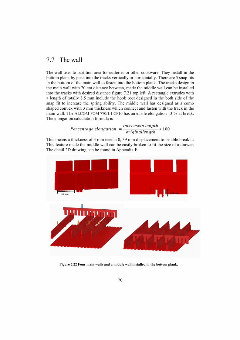
7.7 The wall
The wall uses to partition area for cutleries or other cookware. They install in the bottom plank by push into the tracks vertically or horizontally. There are 5 snap fits in the bottom of the main wall to fasten into the bottom plank. The tracks design in the main wall with 20 cm distance between, made the middle wall can be installed into the tracks with desired distance figure 7.21 top left. A rectangle extrudes with a length of totally 8.5 mm include the hook root designed in the both side of the snap fit to increase the spring ability. The middle wall has designed as a comb shaped convex with 3 mm thickness which connect and fasten with the track in the main wall. The ALCOM POM 770/1.1 CF10 has an ensile elongation 13 % at break. The elongation calculation formula is
∗ 100
This means a thickness of 3 mm need a 0, 39 mm displacement to be able break it. This feature made the middle wall can be easily broken to fit the size of a drawer. The detail 2D drawing can be found in Appendix E.
Figure 7.22 Four main walls and a middle wall installed in the bottom plank.

71
8 Testing and refinement
Chapter 8 presents the testing process of the product and the design changes.
8.1 Parts testing in Ansys
Parts has been put into testing for control the designs can meet the requirements of the product. The material input and contact, mesh setting will be the same as previous test of fixation in Cha. 7.1.1 and 7.1.3, where the contact area between the parts applied finer mesh. The thermal and vibration load will be negligible.
8.2 Testing environment
The different parts have put into different loads test, which can be brief introduced in table 8.1. The bottom plank was tested in contact pressure 0,192 MPa explained in the Cha. 6.2. However, the testing parts are too big, which required a very long simulation time. Therefore, the bottom plank has been changed to a small size 100 *100 mm and a part shaped like the one of four parts of the circle ring see figure 8.1. The conduct pressure load changed to 0, 048 MPa. The dowels tested by estimated the weight of 8 plates and the middle wall estimated the weight of 60 pieces cutlery with a pull acceleration 0,5 m/s. The main wall designed to install vertically, it uses often with the middle wall, which keeps the main wall in a solid position. Therefore, it assumes only need to withstand a minimal load with 30% of the weight of the cutlery set. The side dowel used to keep one plates vertically, which means the force loads estimated 1/8 of the support dowel loads. As the force was distributed applied in the dowel when it partitions several plates. Squares with 1 mm2 with a little depth were sketched to conduct force load. See figure 8.2 green marked area.

72
Figure 8.1 The testing part of the bottom plank.
Figure 8.2 The testing part of the dowel

73
Table 8.1 Magnitude and areas of testing loads.
Parts Loads Area Fig No.
The bottom plank 0,048 MPa Contact surface between the circle ring and the bottom plank*
8.3
The main wall 0,825 N One sides of the wall * 8.6
The middle wall 1,65 N One side of the middle wall install in the main wall*
8.4
The support dowel 1 2,56 N Outside of the support dowel* 8.5
The support dowel 2 2,56N The rectangle support 8.5
The side dowel 0,32 N Into the side of the main dowels* 8.6
* With a fixed support under the down surface of the bottom plank figure 8.3.
Figure 8.3 The testing load of the bottom plank and the fixed support

74
Figure 8.4 The testing load of the middle wall.
Figure 8.5 The test load for the middle wall.

75
Figure 8.6 The testing of side force of the dowel and the main wall.
8.3 Results of the testing From the result of table 8.2, the design have great performance for the testing loads and there are no need to further changes.
Table 8.2 Results of testing and suggested design change areas
Properties Total deformation [mm]
Maximal stress [MPa]
Factor of the safety
Withstand loads?
Refinement
The bottom plank 0,001 0,54 Above 15 Yes No
The main wall 0,00089 0,018 Above 15 Yes No
The middle wall 0,13 0,072 Above 15 Yes No
The main dowel 1 0,15 2,28 Above 15 Yes No
The main dowel 2 0,23 2,47 Above 15 Yes No
The support dowel 1,34 3,98 Above 15 Yes No

76
8.4 Moulding
8.4.1 Mounding process
Injection Moulding is a manufacturing process used widely for producing thermoplastic parts in large volume. It is most typically used in mass-production processes where the same part is being created. This method can keep the production in a low price which is a Must requirement. Duo to the 3-dimensional shaper geometry in variant direction, the dowel and the walls must use injection mould, but the bottom plank has a two-dimensional form in the side, which are continuous in some linear shapes [30]. It could use extrusion as the manufacture process, and later be cut by infrared laser to desired length. However, it needs extra investment for sheet extruder machine, which costs 46000 $[31]. Therefore, chooses to use injection mould as well.
8.4.2 Moulding analysis
After some design change and the final geometry has defined, every part has made a mould analysis in Creo Parametric, where make the simulation of injection moulding. The program will indicate the eventual problems under mould process, suggestion of gate locations and solutions for problems and moulding. It even indicates some important parameters like distribution of the melting time, cooling time and temperatures and so on. A part of the parameters will be used in the cost analysis for calculate the price of every single part of the SMO.
The results revealed the cycle time of the dowel is very long, which will cause a increased manufacture cost and production lead time.

77
Table 8.3 Results of parts molding analysis
Properties The bottom plank The main wall The middle wall The dowel
Moldability Good Low Good Good
Gate number 2 2 2 2
Filling time[s] 2,72 1,46 0,21 0.8
Packing time[s] 13 13 4,83 13
Cooling time[s] 11 6 7,5 14
Mold open time[s] 4 4 4 4
Total cycle time [s] 30,72 26,46 17,54 35,8
Mold temperature range [°C]
60 ~ 120 °C 60 ~ 120 °C 60 ~ 120 °C 60 ~ 120 °C
Cavities 1 1 1 1
Cavity (Part) volume [cc]
405.894 85.928 3.851 11.067
Mold_dimension [mm]
300 x 9.00 x 520.00 7.00x49.00x520.00 57.00x34.00x5.00 92.00 x 54.00 x 18.00
Weight [g] 707 122 5,56 16
Problem Description
Air traps found inside the cavity. This may cause voids or surface defect.
Model is incompletely filled at the end of filling. Short shot may occur.
Air traps Air traps found inside the cavity. This may cause voids or surface defect.
Solution Increase the filling time. Change the gate location. Reduce the injection speed. Modify the size or location of the vents.
Increase the mould temperature or melt temperature. Change the gate locations. Add more gates.
Increase the filling time. Change the gate location. Reduce the injection speed. Modify the size or location of the vents.
Increase the filling time. Change the gate location. Reduce the injection speed. Modify the size or location of the vents.

78
8.5 Cost analysis
The cost of a product has great impact for the popularities of a product. In our case, it is essential that the price is kept on a low level. In this paragraph, a part cost calculator [32] of moulding has used to helping estimate the price of every parts of the SMO and potential areas to be improved to saving cost.
8.5.1 Background of input parameters
In this paragraph, will explain the reason how some of the parameters for part cost calculator have been chosen or estimated.
Annual sale - the more produce, the cheaper becomes to manufacture a product. As lack of the information of the purchase intention, the start production will be 50,000 for bottom plank, 4 times for the middle wall and 9 times more for other parts. The product will be manufactured in China and delivery 2 times a year.
Reject - estimated in calculator 1%.
Material price - The price of the material has many varieties with different qualities. Here used the price list of Katarina [33].
No of parts per packaging box - use 800*600 mm packing box with max 500 kg [34]
Tool cost to be amortised - estimated by a online calculator [35] which developed by a mould tool company in China. The detail cost of moulding tool is shown in Appendix F. The lifetime of the moulding tool is usually 10 years. The cost should be a ten part of the total mould cost.
Masterbatch - used for colouring plastics 1%. Use cheap red with natural UV protection, 21 kr /kg.
Freight per delivery - The mid-range price alternative from China railway express to berlin includes an estimated shipping time to Sweden of 4 days and costs of 10 SEK/kg.

79
8.5.2 Parts price
From table 8.4, we can see a total price for a cutlery holder with 2 bottom planks, 4 main walls and 2 middle walls will cost around 160 kr, which is 62,5% more expensive than the total target price 60 kr was defined in Cha. 3.7 The final specifications. To achieve the total target price, every parts price must be decreased. The target price of the parts based on the quantity of the material use during the molding.
Table 8.4 Estimated parts sale price.
Cost [sek] The bottom plank
The main wall The middle wall The dowel
Manufacturing cost
20,4 6,293 2,49 10,279
Administration cost
1,020 0,315 0,125 0,514
Total cost of production 21,42 6,608 2,615 10,793
Retail price with 30 % profit. 27,846 8,5904 3,3995 14,0309
Target price 15 5 2 2
Deviation 12,846 3,5904 1,3995 12,0309

80
9 Prototyping
In this chapter presents the process of making the prototyping
9.1 3D print
As the bottom plank and the walls are quite big, it only printed out a testing prototype to give a feeling about the tolerance, size and ergonomic for the hands etc. The bottom plank and the main have been printed out with an area of 100 *100 mm and the wall length 100 mm.
Figure 9.1 3D printed bottom plank and main wall.

81
Figure 9.2 3D printed dowel

82
Figure 9.3 The assembly of the walls
9.2 Valuation of the prototype
By observing and testing of the prototype, revealed both good and bad side of the design. The positive of the design are the wall and bottom plank have a attractive design and the fixation solution made you feel free to install in both directions, However, there are also many issues revealed and need to be improved. The design of the dowel doesn’t look attractive, the support dowels are not stable and the size seems too small to get a feeling of quality or long-life time. The snap fits seem too small.

83
9.3 Render prototype in Creo
Figure 9.3 Rendering picture of use of SMO as cutlery holder.
Figure 9.4 Exhibition for other using area.

84
10 Conclusion and discussion
In this Chapter presents concluding of the fulfilment of requirements and even furthering developing work recommendations of the SMO.
10.1 Fulfilment of specifications and requirements The mechanical analysis of the Cad geometry of the SMO indicates the test of the parts abilities of withstand loads with high safety factor, which provides the information that the SMO functioned as intended.
Table 10.1 Fulfillment of customer requirements.
No Customer requirements Fulfillment
1 The fixture solution must be easily to install and stable. Yes
2 The fixture has good appearance. No
3 The size must increase. Yes
4 The SMO must include assembly solutions Yes
5 Solution for general organize. Yes
6 It must avoid gaps between the walls connections. Yes
7 The modelling time must decrease. Yes
8 The price of the SMO must be lower than 60 kr. No
9 It must fasten on the drawer or cabinet bottom. No
10 It must be tough, anti-scratch Yes
11 The dowels must be stiff. Yes
12 It must be water resist. Yes
85
10.2 Further work
While this thesis has addressed a variety of issues regarding the SMO, there is still scope for further investigation in the following areas.
10.2.1 The sale unit
As the SMO can be used for many organiser purposes, but quite often the end user doesn’t have or willing spend a long time to explore. One or two standard sale packages with several partition applications for organising plates or cutleries may raising the purchase interest for giving customer some smart organising ideas.
10.2.2 Better and smarter assembly solutions
The bottom plank has a standard dimension, which can be enlarged by assembling another bottom plank. However, it still needs to be cut to achieve another dimension. When a bottom plank has been cut, it wouldn’t be able reversed back to the intimal part, which cause unnecessary waste. A better solution can be implemented in this case for instant, a foldable edge design so the redundant edge can stand beside a drawer interior edge. Or it can be improved with more flexible and user-friendly solution such as snap fit.
10.2.3 Reduce parts cost
From Table 8.4 is shown the sale price of each part of the SMO are substantially exceed the target prices, which indicates a part of simplifications need to make in both design and construction. The dowel may start reconsidering whether need to keep the support dowels, as it increases the cost of moulding tool and production cycle time. Using extrusion as moulding method for the bottom plank can be further investigated if there are company can manufacture in both injection and extrusion method with low price. Furthermore, the material selection analysis includes the mould cost and mechanical testing can be taken into consideration in the research if there are better material alternatives. The currently material has very high safety factor during the mechanical test, a cheaper alternative like Polyethylene (PE) with 30 % glass fibre or ABS may be a more economic choice.

86
10.2.4 Further end user test
The final prototype is not tested with the end user due to the time elimination. By interviewing and testing the final product again can collect many good suggestions and improvements, even the purchase intention can also be estimated and used later for ordering.
10.2.5 Integral the walls solutions
The current solution of creating cutlery holder needs both the main and middle wall. The middle wall can’t be used without supporting from the main wall. If the two walls can be integral with one solution, it will reduce the start investment. 10.2.6 More advanced mould analysis
From the tabell 8.2 indicates the moldability of the main wall is low, and the model will be incompletely filled under the injection. The figure 10.1 shows the contribution of the gates are near 0% and the red area means plastic filled only with one gate with 0, 01 %. In this case, a more advanced mould analysis needed to be made to calculate and find the eventually problems or design changes.
Figure10 1 The moldabilty and gate contribution

87
10.3 Reflection
Once the thesis is close to the end is time for a self-evaluation of the work done in this period. This project started at the middle April with an investigation of potential market and the patens for the concept idea. When a clear signal got from the patens research, a thoughtful product development process was being made duo to the fact that the concept idea was already defined in the beginning.
The project was planned to be finished at the end of the September, but the time has been delay several times. During the execution of the thesis, many of the issues had been underestimate the complexity of working with the design, construction testing and cost. Those actions have strong link with each other, and a change of any of them will need a responds adjustment in several areas, which are time consuming. However, it teaches me the importance of the communication between engineer, designer and economist, which is useful experience for my further work.
Duo the limitation of the time, the SMO has only finished a part of the work, many areas still need to be improved before it can be mass produced. Despite this, I am satisfied with the achieved results during this thesis and appreciate the great opportunity and experience to bring my idea into reality.

88
References
[1] The gardian (2014). Are tiny houses and micro-apartments the future of urban homes? Retrieved October 10, 2017, from https://www.theguardian.com/sustainable-business/2014/aug/25/tiny-houses-micro-living-urban-cities-population-newyork-hongkong-tokyo
[2] AyA kitchen.(n.d.). Retrieved October 10, 2017, from http://www.ayakitch-ens.com/design/form_function/organization_cutlerytray.html
[3] Ulrich, K, T & Eppinger, S, D (2014). Produktutveckling Konstruktion och Design. Studentliteratur AB, Lund, Sverige
[4] Eriksson M. & Lilliesköld, J. (2004). Handbok för mindre projekt. Stockholm: Liber AB.
[5] Diegel, O. (2016). Patents [PowerPoint slides]. Division of Machine Design, Department of Design Sciences LTH, Lund University, Lund, Sweden.
[6] Charlane, M. C. (2002). Selectively configurable household accessory holder. Google patents US6769538
[7] Andrew L. B. (2003). Expandable drawer organizer. Google patents US7066563
[8] IKEA, (2012-2013). Retrieved October 10, 2017, from http://www.itcdeganutti.org/attivita/lingue/2012-13/IKEA.pdf
[9] IKEA köphjälper, (2016) Retrieved October 10, 2017, from http://www.ikea.com/ms/sv_SE/pdf/kophjalp/fy16/IKEA_Kophjalp_METOD_2016.pdf
[10] MIXIMERA. (n.d.). Retrieved October 10, 2017, from http://www.ikea.com/au/en/catalog/products/10271251/
[11] Duowing avdelare. (n.d.). [Online] https://epoq.se/produkter/duowing-avdelare/
[12] HTH katalogen. (n.d.). Retrieved October 10, 2015, from http://ipaper.ipapercms.dk/Nobia/HTH/SE/En_extra_krydda/
[13] Sorto färdiganpassade set 50 cm, Eqop. Elgigantan . (n.d.). Retrieved October 10, 2015, from https://epoq.se/produkter/sorto-fardiganpassade-set-50-cm/
[14] Drawer from Ikea. (n.d.). Retrieved October 10, 2015, from http://www.ikea.com/au/en/catalog/products/80271115/
[15] Anthony, U. (2005), “What Customers want”, McGrew Hill
[16] Olivia, (2011). Difference between Observation and Interviewing as Methods of Data Collection. Retrieved October 10, 2017, from http://www.differencebetween.com/difference-between-observation-and-vs-inter-viewing-as-methods-of-data-collection/

89
[17] Ulrich. K.T. (1996). The role of product architecture in the manufacturing firm. Massachusetts Institute of Technology, Cambridge, USA
[18] Mark. M., 8 Fundamental Ergonomic Principles for Better Work Performance. Retrieved October 10, 2017, from http://ergo-plus.com/fundamental-ergonomic-principles/
[19] DIGI key product. Retrieved October 10, 2017, from https://www.digikey.com/en/product-highlight/e/essentra-components/snap-rivets
[20] Ulf, B. (2015). User’s guide to plastic. Hanser Publishers
[21] Omnexus, polymer properties Retrieved October 10, 2015, from http://omnexus.specialchem.com/polymer-properties/properties/max-continuous-ser-vice-temperature
[22] Chul Lee (n.d.) BASF Retrieved October 10, 2017, from https://knowledge.ulprospector.com/1235/pe-snapfit-1/
[23] Chul, L. (2009). Materials Selection. Retrieved October 10, 2017, from https://knowledge.ulprospector.com/1258/pe-snapfit-4/
[24] Bayer, Material science, Retrieved October 10, 2017, from http://fab.cba.mit.edu/classes/S62.12/people/vernelle.noel/Plastic_Snap_fit_de-sign.pdf
[25] Chul, L. (2009). Improving Snapfit Design. Retrieved October 10, 2017, from https://knowledge.ulprospector.com/1248/pe-snapfit-3/
[26] Calculator. (n.d.). Retrieved October 10, 2015, from https://www.polyplastics.com/Calc/snapfit.do?_LOCALE=ENGLISH
[27] BASF. (2010). Snap-Fit Design Manual. Retrieved October 10, 2017, from http://web.mit.edu/2.75/resources/random/Snap-Fit%20Design%20Manual.pdf
[28] DuPont. (2000). General Design Principles for DuPont Engineering Polymers. Re-trieved October 10, 2015, from http://www.dupont.com/content/dam/dupont/products-and-services/plastics-poly-mers-and resins/thermoplastics/documents/General%20Design%20Principles/Gen-eral%20Design%20Principles%20for%20Engineering%20Polymers.pdf
[29] Deutsches Institut für Normung (DIN). (1982) 16901 Engineering plastics Tolerance
[30] Engineered Profiles (2016) Retrieved October 10, 2015, from http://www.engineeredprofiles.com/plastic-extrusion-vs-injection-molding/
[31] Nanjing Haisi Extrusion Equipment Co. Sheet extruder machine. (n.d.). Retrieved October 10, 2015, from http://hsextruder.en.made-in-china.com/product/gKxmUTXcOPWq/China-PLA-PLC-Biodegradable-Plastic-Sheet-Extrusion-Machine.html
[32] Brucon. (n.d.) Part cost analysis. [Download]www.brucon.se
[33] Katarina. E. H. (2017). Material pris [PDF] Division of Machine Design, Department of Design Sciences LTH, Lund University, Lund, Sweden.
[34] Packaging Handbook for Suppliers, Schaeffer group.

90
Retrieved October 10, 2017, from http://www.schaeffler.hu/remotemedien/media/_shared_media/12_suppliers/ship-ping_and_transport_instructions/packaginghandbook/VHB_201103_en.pdf
[35] Injection Mould Price Estimator. Retrieved October 10, 2017, from http://www.sourcing-cn.com/moldcalc_input.asp

91
Appendix A Work time plan
Figure A.2 Planned and performed activities.
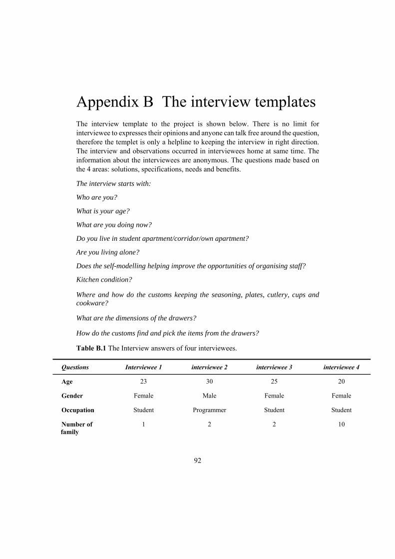
92
Appendix B The interview templates The interview template to the project is shown below. There is no limit for interviewee to expresses their opinions and anyone can talk free around the question, therefore the templet is only a helpline to keeping the interview in right direction. The interview and observations occurred in interviewees home at same time. The information about the interviewees are anonymous. The questions made based on the 4 areas: solutions, specifications, needs and benefits.
The interview starts with:
Who are you?
What is your age?
What are you doing now?
Do you live in student apartment/corridor/own apartment?
Are you living alone?
Does the self-modelling helping improve the opportunities of organising staff?
Kitchen condition?
Where and how do the customs keeping the seasoning, plates, cutlery, cups and cookware?
What are the dimensions of the drawers?
How do the customs find and pick the items from the drawers?
Table B.1 The Interview answers of four interviewees.
Questions Interviewee 1 interviewee 2 interviewee 3 interviewee 4
Age 23 30 25 20
Gender Female Male Female Female
Occupation Student Programmer Student Student
Number of family
1 2 2 10

93
Living type Student apartment First-hand rental apartment
Student apartment Corridor
Kitchen condition
Old kitchen Quite new kitchen
Very old kitchen More than 10 years
How many lunch boxes?
More than 10 More than 10 More than 10 More than 30
Difficult to organize
Yes. sometimes I need to take out most of the boxes to find right cover or boxes
I do not know. I would like to see some new ways to organise the
boxes
Yes. I have so many lunch boxes. I can find right cover. I
often cannot close the drawer.
We share lunch boxes. People just put it in the cabinet. It is falling all the time.
Where do you keep it?
Cabinet Drawers Drawers Cabinet
Where do you buy organiser?
Ikea Ikea Ikea, second hand, Öob
Ikea
Did you buy Variare Serie?
Yes, a cutlery tray. I have Ikea kitchen. The
cutlery tray is included.
No. It does not fit my kitchen
No
It fits well? No. I cut it to fit the drawers
Yes. No No
It is difficult to find tableware?
Yes No No Sometimes
Some problem?
Too many things in cabinet.
The cookwares take too much
space
The cabinet is too deep
I do not know
Interesting to modeling organizer self?
Yes Yes Yes It depends how it is. If it does not
take so long time
Reuse? Important It would be nice. Important Important
Price Under 100 kr Cheap as possible
Cheap Cheap with good quality

94
Appendix C Calculations The stress load for bottom plank
Total mass of ten plates: 0.64 ∗ 8 5,12
Total mass produces to the top surface of the bottom plank:
5,12 ∗ 9,81 50,22
(The friction force is negligible for the worst-case scenario. If the product withstands the load without the friction, then it will withstand it with the friction)
Figure C.1 The circle ring support under a plate.
Stress for total force apply on the circler ring area of a plate with 28 cm diameter estimated:
∗ 8.5 8.1 20,8
50,220,00208
0,024
Stress for total force apply on the circler ring area of 8 plates:
0,024 ∗ 8 0,192

95
Calculation of force load for testing
Figure C. 2 The force illustration.
Assumption
The friction stands the plates and the bottom plank move with the pull force, in order to provide high safety ratio, the friction is negligible.
The drawer’s depth is 60 cm and it can put out maximal the 50 cm.[C1] and it takes 1 second.
A plate weights 0, 64 kg. [C2] A cutlery weights 0, 06 kg. Totally 3, 13 kg for 60 pieces. [C3] The right is positive direction Only calculate the static to pull dynamic action The force applied from the plates to the dowel will be the same from
static to pull action or pull action to static. The weight of the bottom plank is negligible
The pull force acceleration: .
0,5 / ^2
If the friction is negligible, the plate will move to negative direction 1, and it is the same force applied for the dowel with opposite direction see figure C.1.
1
In normal case, it will keep around 8 plates. 0,64 ∗ 8 5,12
1 0,5 ∗ 5,12 2,56
The cutlery set with 60 pieces m= 3, 31 kg
3,31 ∗ 0,5 1,655

96
[C1] IKEA, base drawer. (n.d.). Retrieved October 10, 2017, from http://www.ikea.com/aa/en/catalog/products/30271113/ [C2] IKEA, plate. (n.d.).Retrieved October 10, 2017, from http://www.ikea.com/se/sv/catalog/products/80289182/ [C3] IKEA, cutlery. (n.d.).Retrieved October 10, 2017, from http://www.ikea.com/se/sv/catalog/products/80188654/

97
Appendix D Drawing for parts
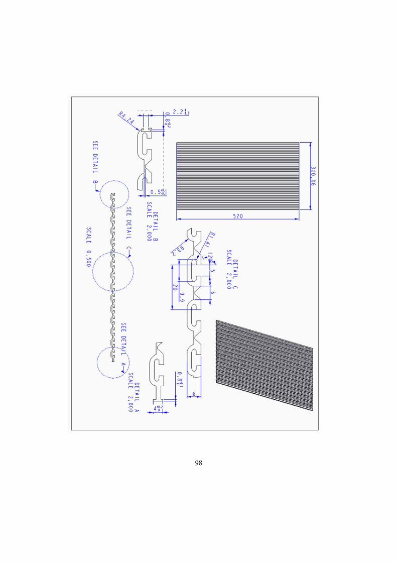
98

99

100

101
Appendix E Results of the testing
.
Figure E.1 The equivariant stress and the total deformation of the bottom
Figure E.2 The force applied in the middle wall.

102
Figure E.3 The equivariant stress and the total deformation of testing the main dowel 1.
Figure E.4 The equivariant stress and the total deformation of testing the main dowel 2.
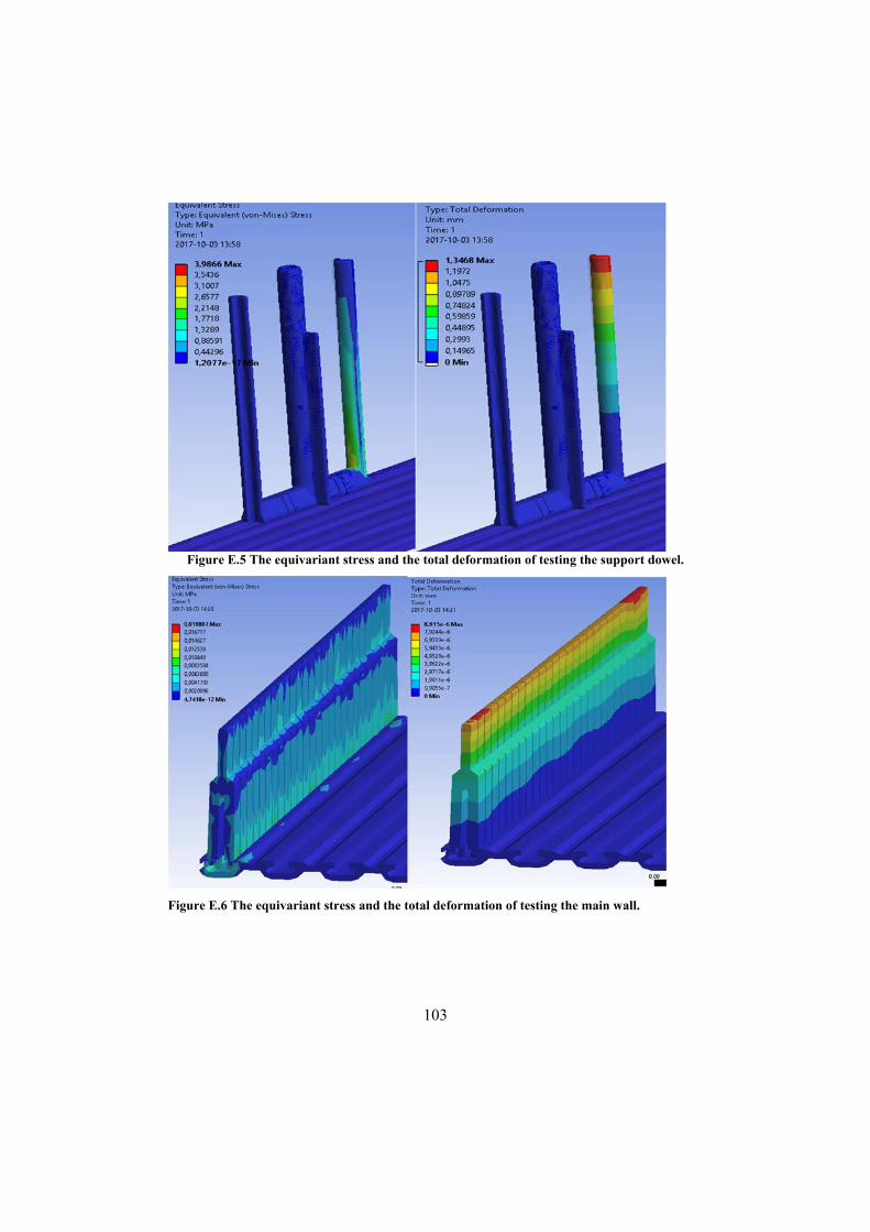
103
Figure E.5 The equivariant stress and the total deformation of testing the support dowel.
Figure E.6 The equivariant stress and the total deformation of testing the main wall.

104
Appendix F Tool cost detail
Table F.1 The price estimated for aluminum injection molding tool in Swedish krona.
Items The bottom plank
The main wall
The middle wall
The dowel
Mold core 3024 4508 127 258
Mould frame 4078 5517 1022 1145
Other material cost
2933 4259 293 410
CNC machining
8429 11999 1212 1523
Laboring 4000 4000 4000 4000
Electrode machining
1210 1803 51 103
Wire cutting 907 1352 38 77
Mould design cost
2158 3044 374 452
Mould testing design
2018 2018 2018 2018
Factory overhead and
profit
8500 11715 2025 2305
Tax 5824 8027 1387 1579
Total mould price
40080 55242 9548 10870
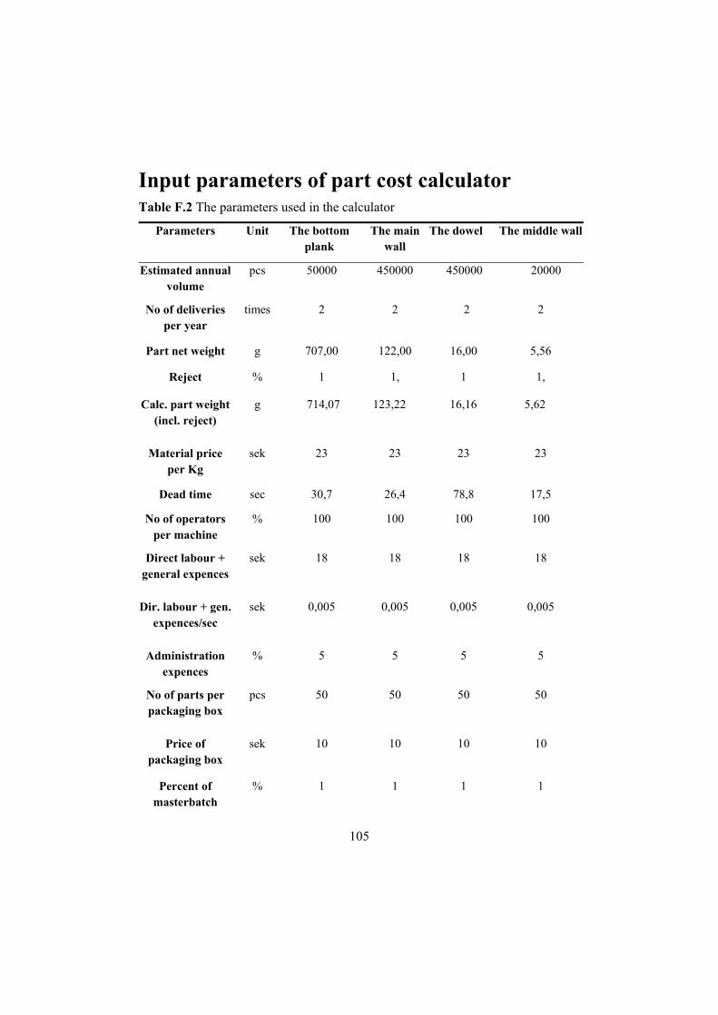
105
Input parameters of part cost calculator Table F.2 The parameters used in the calculator
Parameters Unit The bottom plank
The main wall
The dowel The middle wall
Estimated annual volume
pcs 50000 450000 450000 20000
No of deliveries per year
times 2 2 2 2
Part net weight g 707,00 122,00 16,00 5,56
Reject % 1 1, 1 1,
Calc. part weight (incl. reject)
g 714,07 123,22 16,16 5,62
Material price per Kg
sek 23 23 23 23
Dead time sec 30,7 26,4 78,8 17,5
No of operators per machine
% 100 100 100 100
Direct labour + general expences
sek 18 18 18 18
Dir. labour + gen. expences/sec
sek 0,005 0,005 0,005 0,005
Administration expences
% 5 5 5 5
No of parts per packaging box
pcs 50 50 50 50
Price of packaging box
sek 10 10 10 10
Percent of masterbatch
% 1 1 1 1

106
Masterbatch price per Kg
sek 21, 21 21 21
Net cycle time (measured)
sec 30,7 26,4 78,8 17,5
No of cavities pcs 1 1 1 1
Parts per hour (theoretical)
pcs 117,2 136,4 45,74 205,2
Parts per hour (real)
pcs 110,2 128,3 43,042 193,0
Usability % 95 95 95 95
Time per part (theoretical)
sec 30,72 26,40 78,80 17,54
Time per part (real)
sec 32,66 28,07 83,79 18,65
Machine cost per hour
sek 400 400 400 400
Tool cost to be amortised
sek 4008 5524 955 1087
Tooling change time per delivery
hours 1 1 1 1
Cost for tooling change
sek 418 418 418 418
Sales price (gross) sek 30 15 15 5
Freight per delivery
sek 350000 459000 72000 25200