
Self-Leveling Tabs
8
SLT6 & SLT10 KITS OWNER’S MANUAL AND INSTALLATION INSTRUCTIONS SAVE AND KEEP WITH BOAT OWNER’S INFORMATION SLT6 SLT10 Self-Leveling Tabs
Transcript of Self-Leveling Tabs

SLT6 & SLT10 KITS
OWNER’S MANUAL AND INSTALLATION INSTRUCTIONS
SAVE AND KEEP WITH BOAT OWNER’S INFORMATION
SLT6
SLT10
Self-Leveling Tabs

Congratulations on your purchase of a Bennett SLT System — an affordable, simple solution for small boats from 10 to 20 feet (3 m to 6 m). Now you have the durability of a Bennett trim tab system with a quick and easy installation. Your new Self-Leveling Tabs (SLT) will improve your ride and boost your boat’s performance:
How they workThe SLT reacts instantly to boat speed and water pressure by adding trim when it’s needed. At slower speeds, when the boat is trying to get on plane, the actuators hold the trim tabs down, which lifts the stern and simultaneously puts the boat at planing attitude. On plane, and as the boat’s speed increases, water pressure pushes the tabs up. You get a better ride while the SLT does all the work.
Quick and easy installationAs you will see on the following pages, installing a Bennett SLT Sys-tem can be done with just a few tools and in less than an hour. You can also change the position of the actuator on the tab with adjust-able mounting options.
Part # Tab Size Tab Boat SizeSLT6 6" x 8"
(15 cm x 20 cm)10' - 14'(3 m x 4.5 m)
SLT10 10" x 10"(25 cm x 25 cm)
14' - 20'(4.5 m x 6 m)
You selected your kit using this guideline:
If you have any questions about your kit, please contact Bennett client service at 954.427.1400 (8 a.m. to 5 p.m. Eastern time) or email [email protected].
2
• Plane at lower speeds
• Improve your hole shot
• Improve fuel efficiency
• Reduce engine laboring
• Reduce pounding
• Eliminate porpoising and chine walking

Complete SLT Parts List and Diagram
SLT6 SLT10Trim Tab Only TPOSLT6 - Qty 2 TPOSLT10 - Qty 2
Hinge Plate HPSLT6 - Qty 2 HPSLT10 - Qty 2
Backing Plate BPSLT6 - Qty 2 BPSLT10 - Qty 2
Complete Actuator A1200SSLT50 - Qty 2
A1200SSLT80 - Qty 2
Actuator Pin SLT500 - Qty 2 SLT500 - Qty 2
Hardware BagIncludes parts below:
H1170SLT H1170SLT
Actuator Upper Hinge Screw
(#14 x 1 ½" Screw)
H1174 - Qty 6 H1174 - Qty 6
Trim Tab Screw(#10 x ¾" Screw)
H1198 - Qty 10 H1198 - Qty 10
Mounting Bracket SLT501 - Qty 2 SLT501 - Qty 2
Actuator Lower Hinge Screw
(1/4-20 x ¾" Philips Head Machine Screw)
H1175 - Qty 4 H1175 - Qty 4
123
4
1
5
6
2
3
4
5
98
7
6
7
8
9
3
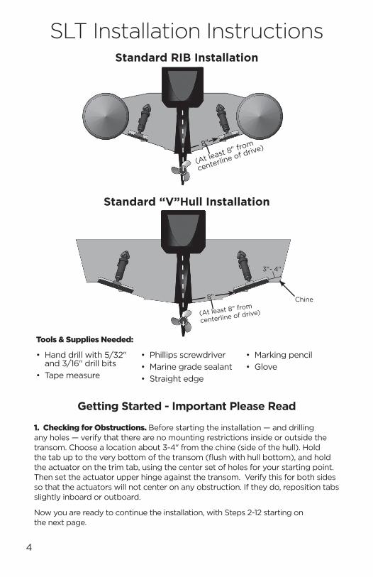
Standard RIB Installation
Standard “V”Hull Installation
4
Getting Started - Important Please Read
1. Checking for Obstructions. Before starting the installation — and drilling any holes — verify that there are no mounting restrictions inside or outside the transom. Choose a location about 3-4" from the chine (side of the hull). Hold the tab up to the very bottom of the transom (flush with hull bottom), and hold the actuator on the trim tab, using the center set of holes for your starting point. Then set the actuator upper hinge against the transom. Verify this for both sides so that the actuators will not center on any obstruction. If they do, reposition tabs slightly inboard or outboard.
Now you are ready to continue the installation, with Steps 2-12 starting on the next page.
SLT Installation Instructions
(At least 8" from
centerline of drive)8"
(At least 8" from
centerline of drive)
8" Chine
3"- 4"
• Hand drill with 5/32" and 3/16" drill bits
• Tape measure
• Phillips screwdriver• Marine grade sealant• Straight edge
• Marking pencil• Glove
Tools & Supplies Needed:
SLT Installation Instructions cont.
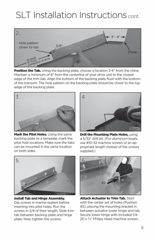
2.
Position the Tab. Using the backing plate, choose a location 3-4" from the chine. Maintain a minimum of 8" from the centerline of your drive unit to the closest edge of the trim tab. Align the bottom of the backing plate flush with the bottom of the transom. The hole pattern on the backing plate should be closer to the top edge of the backing plate.
Mark the Pilot Holes. Using the same backing plate as a template, mark the pilot hole locations. Make sure the tabs can be mounted in the same location on both sides.
3. 4.
Drill the Mounting Plate Holes, using a 5/32" drill bit. (For aluminum boats, use #10-32 machine screws of an ap-propriate length instead of the screws supplied.)
Install Tab and Hinge Assembly. Dip screws in marine sealant before inserting into pilot holes. Run the screws in 3/4 of their length. Slide trim tab between backing plate and hinge plate. Now, tighten the screws.
5. 6.
Attach Actuator to Trim Tab. Start with the center set of holes (Position #2), placing the mounting bracket in between actuator lower hinge and tab. Secure lower hinge with included 1/4-20 x ¾" Philips Head machine screws.
5
Hole pattern closer to top
Chine
3"- 4"
At least
8" from
centerline of drive
5/8"
#2
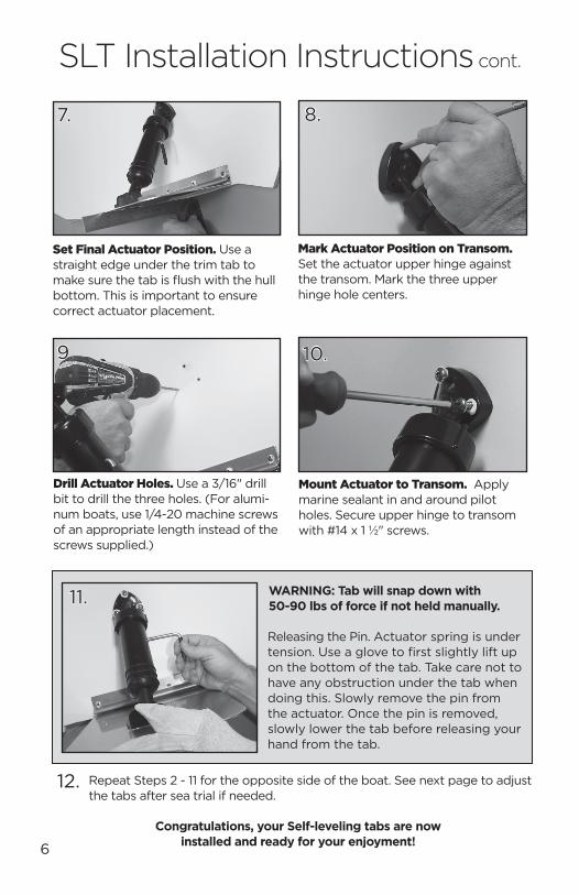
Mark Actuator Position on Transom. Set the actuator upper hinge against the transom. Mark the three upper hinge hole centers.
8.
Drill Actuator Holes. Use a 3/16" drill bit to drill the three holes. (For alumi-num boats, use 1/4-20 machine screws of an appropriate length instead of the screws supplied.)
11.
Releasing the Pin. Actuator spring is under tension. Use a glove to first slightly lift up on the bottom of the tab. Take care not to have any obstruction under the tab when doing this. Slowly remove the pin from the actuator. Once the pin is removed, slowly lower the tab before releasing your hand from the tab.
7.
Set Final Actuator Position. Use a straight edge under the trim tab to make sure the tab is flush with the hull bottom. This is important to ensure correct actuator placement.
Mount Actuator to Transom. Apply marine sealant in and around pilot holes. Secure upper hinge to transom with #14 x 1 ½" screws.
10.
WARNING: Tab will snap down with 50-90 lbs of force if not held manually.
Congratulations, your Self-leveling tabs are now installed and ready for your enjoyment!6
Repeat Steps 2 - 11 for the opposite side of the boat. See next page to adjust the tabs after sea trial if needed.
12.
9.
SLT Installation Instructions cont.
Saving the Pin: This allows you to put your SLT tabs in the retracted position when not on the water. You may wish to do this for beaching, trailering or rack storage. Reinsert the pin following the reversed method used in Step #11 on page 6.
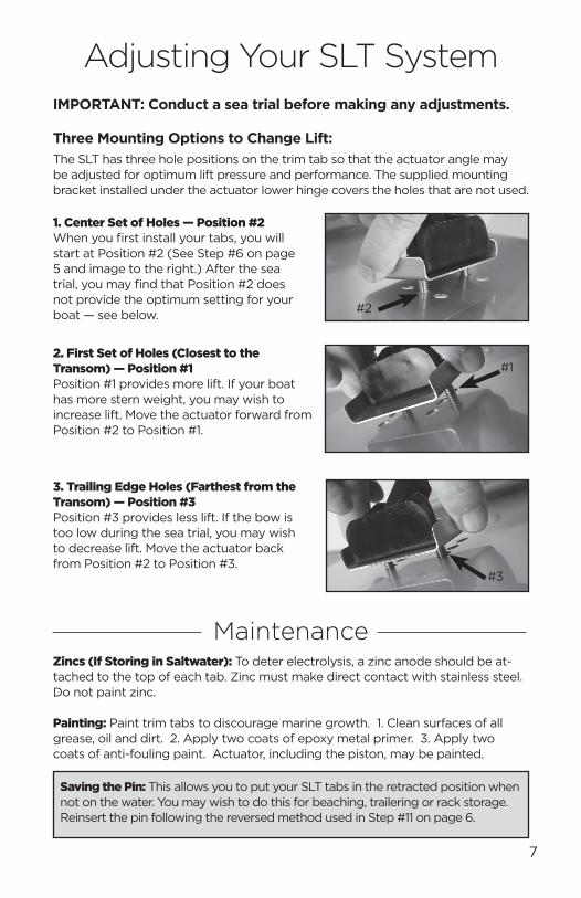
Three Mounting Options to Change Lift:
IMPORTANT: Conduct a sea trial before making any adjustments.
1. Center Set of Holes — Position #2 When you first install your tabs, you will start at Position #2 (See Step #6 on page 5 and image to the right.) After the sea trial, you may find that Position #2 does not provide the optimum setting for your boat — see below.
2. First Set of Holes (Closest to the Transom) — Position #1 Position #1 provides more lift. If your boat has more stern weight, you may wish to increase lift. Move the actuator forward from Position #2 to Position #1.
The SLT has three hole positions on the trim tab so that the actuator angle may be adjusted for optimum lift pressure and performance. The supplied mounting bracket installed under the actuator lower hinge covers the holes that are not used.
3. Trailing Edge Holes (Farthest from the Transom) — Position #3 Position #3 provides less lift. If the bow is too low during the sea trial, you may wish to decrease lift. Move the actuator back from Position #2 to Position #3.
Zincs (If Storing in Saltwater): To deter electrolysis, a zinc anode should be at-tached to the top of each tab. Zinc must make direct contact with stainless steel. Do not paint zinc. Painting: Paint trim tabs to discourage marine growth. 1. Clean surfaces of all grease, oil and dirt. 2. Apply two coats of epoxy metal primer. 3. Apply two coats of anti-fouling paint. Actuator, including the piston, may be painted.
Maintenance
7
#2
#1
#3
Adjusting Your SLT System
BENNETT WARRANTY
SLT7 r052417
Bennett SLT actuators in the United States carry a Limited Lifetime Warranty against manufacturing defects. Limited Lifetime Warranty refers to the life of the product, not the boat, or the owner. Limited Lifetime Warranty ends when the product becomes unusable for reasons other than manufacturing defects.
PLEASE NOTE: Damage to the trim tabs due to electrolysis is not covered by warranty. No labor costs of replacement, haulout, or miscellaneous charges are covered. Contacting Bennett Marine first may save considerable time, trouble and expense.
The foregoing is in lieu of any and all other warranties, expressed or implied, in-cluding any warranty of merchantability or fitness for a particular purpose. There are no other warranties which extend beyond that set forth above.
Warranty Return Procedure: We recommend that you contact us first to troubleshoot your system and determine the best solution. We take great pride in providing the best client service. Simply call 954.427.1400 or send an email to [email protected]. We will be glad to assist you.
U.S. Customers: Simply return the faulty part to Bennett Marine along with our Quick and Easy Product Return Form found on the Warranty page of our web-site: www.BennettTrimTabs.com/warranty. Parts covered under warranty will be repaired or replaced without charge.
Customers Outside the USA: Please contact your local Bennett Marine distributor for warranty and return procedures in your respective country.
550 Jim Moran Blvd • Deerfield Beach, FL 33442 USAPh: 954.427.1400 • Fax: 954.480.2897www.BennettTrimTabs.com