Self Closing & Electric Operation - Ready Access · Model BO-10 Bump Out 10 Self Closing & Electric...
40
Model BO-10 Bump Out 10 Self Closing & Electric Operation Pass-Thru Window
Transcript of Self Closing & Electric Operation - Ready Access · Model BO-10 Bump Out 10 Self Closing & Electric...

Model BO-10Bump Out 10
Self Closing & Electric Operation
Pass-Thru Window

2
TABLE OF CONTENT
Topic Page
Disclaimer 3
Serial Number Identification 3
Contact Sheet 3
Introduction 4
Product Information
Description 4
Specifications 6
Dimensions 6
Safety Information 6
Installation Procedures
Tools needed 7
Materials Needed 7
Physical Installation 8
Electrical Installation 13
Initial Operations and Testing 15
Adjustments and Calibrations 16
Operational Procedures
Modes of Operation 21Operations 21Control Identification, Explanation and Function 22
Maintenance
Maintenance Schedule 23Daily 23Monthly 23Yearly 23
Service
Troubleshooting Guide (Cause and Effect) 24Parts Lists
Common Replacement Parts (Description/Part Number) 27Complete Parts List (Description/Part Number) 28
Drawings - Exploded Views / Schematics 31Appendix A – Adjusting or Re-Hanging the Doors 39

3
DISCLAIMER
READY ACCESS DISCLAIMS ANY LIABILITY FOR ANY DAMAGE OR HARM CAUSED TO THE BO-10 DRIVE-THRU WINDOW, IT’S OPERATOR OR ANY OTHER EQUIPMENT HOWEVER CAUSED IF THE BO-10 DRIVE-THRU WINDOW IS REPAIRED OR SERVICED BY ANYONE OTHER THAN AN AUTHORIZED SERVICE ENGINEER OR CONTRARY TO THE MANUFACTURERS WRITTEN INSTRUCTION CONTAINED HEREIN.
THIS MANUAL IS INTENDED FOR USE BY THE IN-HOUSE OR AUTHORIZED FIELD SERVICE ENGINEERS AND SALES REPRESENTATIVES
The manufacturer maintains the right to update, add or issue a new service manual at any time without notice, thereby rendering all previous issues obsolete.
Please write the Serial Number and Installation Date for your drive-thru window in the spaces provided.
Serial Number
Date of Installation
The serial numbernameplate is locatedon the post
CONTACT INFORMATION FOR SALES AND SERVICE CONTACT
Ready Access Tel: 630-876-7766 1815 Arthur Drive Tel: 800-621-5045 West Chicago, Illinois 60185 Fax: 630-876-7767 Email: [email protected] Website: www.ready-access.com

4
INTRODUCTION
The Ready Access window is quality designed to give you years of reliable, trouble-free service. Each window is shipped pre-assembled, fully glazed and ready for installation. All Ready Access windows are thoroughly tested prior to shipping.
The BO-10 Bi-Parting Window is the perfect enhancement to the drive-thru concept, offering unobstructed views of customer and crew.
The BO-10 comes in two versions, manual/Self Closing and electric. The electric version is fully automatic with a manual override in case of a power outage. The doors will open and close by stepping into an out of the light beam sensor. Both models meet health department requirements for self-closing units.
This classic bump out design offers a panoramic view of cars and outside activity. Convenience is key with over four feet of inside usable counter space and a large 18"W x 23"H (483mm W x 584mm H) service opening. Available in manual or electric operations, the Bump Out 10 is a practical choice for any business.
PRODUCT INFORMATION
• Large 18"W x 23"H (483mm W x 584mm H) Service OpeningPerfect for virtually any size order, the Bump-Out 10 features a bi-parting door openingfor operating convenience.
• Panoramic ViewThis original bump-out design offers the operator a 3-sided view of cars and outsideactivity.
• Counter SpaceThe Bump-out 10 has over 4 feet of usable inside counter space for condiments andother necessities.
• Quality ConstructionAnodized aluminum extrusions, stainless steel and 1/4" tempered glass combine to giveyou an attractive window that not only enhances building exteriors, but will not rust, pit orweather. Track free bottom sill provides for a contaminant free surface.
• Double Security LocksBump-Out 10 Windows automatically lock each time the doors close, providing securitywhen the window is unattended. When the drive-thru is closed, manual security lockshelp to prevent outside entry. An optional security bar set is available for high risk areas.
• Fully Assembled, Ready to InstallReady Access windows are shipped completely preassembled, and fully glazed for lowerinstallation costs. Normal installation takes less than two hours.

5
• Five Day Shipping
Ready Access will typically ship any standard window order 5 days from receipt of order.
• Warranty and Service SupportYour Bump-Out 10 comes with a one year limited warranty on parts and labor. Inaddition, each unit is backed by a world-wide service organization.
MANUAL/SELF CLOSING OR FULLY-AUTOMATIC SERVICE OPENINGS
• Manual/Self ClosingIn a Manual / Self Closing operation, simply release the self latching handle and pullopen the door. Both doors part from the center and easily slide open. To close thewindow simply let go and gravity will close the window.
• Fully-AutomaticThe operator simply steps into an electronic light beam which opens the door panelsautomatically. The door panels automatically close when the operator steps away fromthe electronic light beam. By the push of a button, operators can easily adjust thewindow opening size to either 12"W or 18"W.
AVAILABLE OPTIONS
• The Bump-out 10 is available in statuary bronze or clear anodized aluminum.
• Tinted glass is available upon request.
• Powder coat painting is available in a wide range of custom colors.

6
SPECIFICATIONS AND PERFORMANCE
Unit Voltage Model
Number USA International
Actual Unit
Amps
Dimensions In Inches
W X H x D
Weight In Shipping
Carton
BO-10 - E 110/120 VAC 60Hz
220/240 VAC 60Hz
15 A (US) 8 A (Int’l)
53½” x 48¾” x 14¼” 180 lbs
Dimensions
SERVICE OPENING18"W x 23"H
5312"
[1358.9mm]
4834"
[1238.3mm]
1414"
[362mm]
Figure 1
Safety Information
WARNING: To avoid the risk of fire, Electric Shock or injury to persons, observe the following:
1. Before servicing or cleaning the unit, switch the power off at the mechanical switch near the unit(Installed by an Electrician) or the electrical entry service panel/circuit breaker. (Load Center)
• OSHA LOCK OUT – TAG OUT procedures are to be observed to prevent power from beingswitched on accidentally.
2. Any Installation and / or Electrical work must be done by QUALIFIED persons in accordance withall applicable codes / standards and manufacturers recommendations and specifications.
3. DO NOT insert fingers and / or foreign objects into the Drive-Thru Window.DO NOT block or tamper with the unit in any manner while it is in operation.
4. This product must not be used in Potentially Dangerous locations such as Flammable, Explosiveor Chemical – laden environment.

7
Installation Procedures
Tools required to perform the installation
• Electric Drill
• Metal Drill bits –
⅛” (3mm)¼” (6mm)½” (13mm)1” (25mm)
• Screwdrivers – Slotted and Phillips
• Hacksaw
• Jack / Utility Knife
• Flat File – Coarse
• Caulking gun
• ¼” Nut Driver
• Extension Cord
• Masonry drill bit –
¼” (6mm)1” (25mm)1½” (38mm)
• Masonry Hole Saw – 1” (25mm)
• Channel Lock Pliers
• Tape Measurer
• Wire Cutter
• Step Ladder
• Level
Materials required for installation
• Window framing, architect specified and installed in building.(Ready Access recommended material is ⅛“ (3mm) x 1 ¾” (44.5mm) x 4” (102mm) hollowaluminum tubing or glazing channel)
• Electrical Tape
• Wire Nuts
• Caulking – silicone (Color specific to the color of window)
• Connectors for conduit as required
• Shingle type shims – as required to level and plum the window

8
Physical Installation
Before you begin installing your Ready Access Drive-Thru Window, you must determine what type of installation
will be required. Wood Frame, Masonry Framing, etc.
Please refer to the details below and on the next page to pick which one bests fits your application.
13" [330.3mm]
3414"
[870.3mm]
50"[1270.5mm]
54"[1372.0mm]
FIGURE 2A
Internal framing by contractor
ae
Line
ae
Line

9
5312"
[1359.44mm]
4834"
[1238.74mm]
1414"
[362.09mm]
1414"
[362.09mm]
36" [914.76mm]
2312"
[597.14mm]
1212"
[317.63mm]
1014"
[260.45mm]
36"
[914.76mm]
2312"
[597.14mm]
1212"
[317.63mm]
FIGURE 2B

10
WARNING:
TWO PEOPLE ARE REQUIRED FOR THE LIFTING AND INSTALLATION OF THE WINDOW.
1. Confirm that the customer-supplied frame is made to accommodate the dimensions as illustrated onpage 9.
2. Confirm that AC power has been run and is ready for connection to the window.3. Check shipping carton for any shipping damage and remove window from the carton.4. Check window for any shipping damage.
NOTE: There are two wall-mounting applications. The mounting space can be surrounded either by sidelights (windows) or masonry. The illustrations will show both configurations. (Figure 3)
(870mm) ID
49 1/4" (1251mm)
ID50" (1270mm)
34 1/4"
Glass Store Front
Daylight Opening
54" (1372mm)
14 1/4 (362mm)
34 1/4" (870mm)34 1/4" (870mm)
*36" (914mm)*36" (914mm)10 1/4" (260mm)
MASONRY WALLROUGH OPENING
SECTION THRUMASONRY WALL
*MIN. DISTANCE FROM TOPOF COUNTER TO FLOOR
SECTION THRUGLASS STORE FRONT
Figure 3
RECESS MOUNTILLUSTRATION
90%+ of installs are recess mount.
rough opening 54" W x 49.25" H
SURFACE MOUNTILLUSTRATION
ae
Rectangle
ae
Line
ae
Line
ae
Line

11
5. Once the application has been determined, check the daylight opening of the frame being used.The opening dimensions should be 50” wide x 34-1/2” high.
6. For a Fully-Automatic installation, check for the electrical hook-up. The AC electric should beinstalled from the breaker box (Load Center) to the window opening before the installation of thewindow.
7. Using the paper mounting template, drill a quantity of 5, ¼” diameter pilot holes for mounting. (SeeFigure 5) OUTSIDE ONLY – DO NOT DRILL THROUGH THE FRAME.
PaperMountingTemplate
Figure 5
8. Remove the template and drill 5, ½” holes using the ¼” pilot holes.OUTSIDE ONLY – DO NOT DRILL THROUGH THE FRAME.
9. For Fully-Automatic installations, Drill a 1½” hole through the wall as illustrated in Figure 6.(The dimensions shown are from the inside of the building.)
5.50
7" (178mm)
Figure 6
10. Requiring 2 people, remove Ready Access Window from carton and place on top of carton lid toprevent scratching.
Rough Opening Shown from
the Inside looking Out.
Dimensions are taken from the
inside daylight opening of the
frame.

12
11. Person number 1 should remove the bottom cover from the window and organize the mountinghardware.
Person number 2 should apply a bead of caulk to the outside surface of the building window frame.(Reference 1/2" drilled holes for mounting window.)
12. Mount the mullion mounting strip provided to the underneath side of the header frame of the window.Pilot holes are provided in the header frame of the window unit.
Figure 7
13. Requiring 2 people, stand window upright. With one person on each side of the window, lift thewindow into position, aligning the counter top with the building frame sill and the mullion mountingstrip going underneath the rough opening header.
With one person holding the front of the window from falling forward, the other person from theinside will start inserting mounting screws through the mullion strip that has been mounted to thewindow in step 12.
From the outside, insert the 5 well nuts and fasten with the bolts and washers provided, through thebottom, underneath the counter, into the building frame.(Mounting into wood, use lag bolts. Mounting into masonry, use mason anchors.)
Figure 8 14. DO NOT TIGHTEN - Shim unit to be square and plum. Once this has been done, tighten mounting
hardware and snap on mullion mounting strip cover.
15. When the window is fully secured, seal the outside of the window to the frame or building usingsilicone caulk.
.

13
Fully-Automatic Instructions
Electrical Installation
All power must be connected and wired by a qualified electrician and must be in compliance with all state and local codes.
The incoming AC power line must be connected to the receptacle located underneath the counter top. (Per Standard electrical code.) The green “grounding” wire is to be attached to the frame of the unit.
WARNING: Use only 110/120VAC – 60Hz source with a dedicated 15Amp circuit. International power: 220/240VAC – 60Hz with a dedicated 8amp branch circuit.
WARNING: This must be a dedicated circuit. Other electrical equipment must not share the same line from the 15Amp circuit breaker.
WARNING: Turning off the front panel rocker switches does not remove the AC voltage form the unit
WARNING: To disconnect the power completely from this unit, turn OFF the mechanical switch near the unit (Installed by an Electrician) or the electrical entry service panel/circuit breaker panel (Load Center) for this unit.
• OSHA LOCK OUT – TAG OUT procedures are to be observed to prevent power frombeing switched on accidentally.
1. Remove the screws holding on the front cover.2. Wire the AC source line to the receptacle. (See Figure 9)
Figure 9
Receptacle

14
Mounting Electric Eye Housing
1. Position eye housing on the interior wall covering the 1-1/2" hole drilled through for electric cablepassage way.
2. Align the wall mounting brackets on inside finished wall. Use as a template to scribe holes for drilling1/4" holes for plastic mounting anchors.
3. Drill 4 - ¼” (6.5mm) holes using the masonry drill bit.
4. Insert the plastic anchors and mount the brackets with the #10 or #12 screws.
5. Attach electric eye mounting channel to the wall mounting brackets with the (4) 8-32 x 1/2" screwsprovided.
6. Attach the sensor to the brackets and secure.
7. Take electric eye cable and pass through 1" hole into the bottom of the window unit and connect tothe cable marked "ELEC.EYE".
8. Assemble plastic electric eye housings to the electric eye mounting channel.
The inside wall is pictured
for the purpose of illustrationonly. (Not a part of the window)
Figure 10
9. Turn “ON” the power to the unit. (Load center circuit breaker and power switch on the “Control unit”.)
10. Test window operations. See “Testing Procedures”.

15
Initial Window Operation
Testing Procedures
Action Reaction
Turn the power “OFF” at the rocker switch located on the controller unit. Manually open and close the doors several times.
When the doors are opening, the “MOTOR RUN” lamp will illuminate green. When the doors are closing, “MOTOR RUN” lamp will illuminate red. The “POWER” lamp must illuminate during both operations. If neither of these lamps illuminate during any of the processes, proceed to the “Troubleshooting” section.
Turn the power “ON” at the rocker switch located on the controller unit. Break the electric eye beam to open the door.
The doors will open to either a 12” (304.8mm) opening or to an 18” (457.2mm) opening.
With the power “ON” press the opening size button located on the controller unit once and break the electric eye beam to open the doors.
The opening size of the doors will change from the previous setting. (12” to 18” or 18” to 12”)
With the power “ON” break the electric eye beam momentarily to open and close the doors.
The doors will open. They will remain in the open position for either approximately 1.5 or 3.0 seconds before closing. NOTE: The DC-3 PCB allows for longer close delay times. (See the Adjustments and Calibration Section)
With the power “ON” press the “CLOSE DELAY” button located on the controller unit once and break the electric eye beam to open the doors.
The doors will open and the length of time that the doors remain open will toggle between 3 and 6 seconds before closing.
With the power “ON” break the electric eye beam momentarily to open and close the doors. Insert an object at least 4” (101.6mm) wide between the doors as they are closing.
The doors will automatically reverse their action (the doors will open), when an object is caught between or restricting the closing of the doors.

16
Adjustments and Calibrations
Door Alignment
Adjustments to the door’s height and alignment are accomplished by turning one or both of the eccentric adjusting nuts located at the top of the doorframe where it mounts to the slide track. (Figure 11)
Eccentric Nuts
Figure 11
Eccentric Adjusting nut

Universal DC3 Window controller
Installation Instruction 1) Determine what model window you have.
2) Set 4 pin dip switch that corresponds with window see chart on control board
(please note on/off directional arrows on dip switches.)
(Do not confuse 5 pin dip switch as this is the time delay for the door to close.
3) Turn Power off on window unit.
4) Remove control panel and or cover.
Note: on window models 275&131 the controller needs to be removed before
disconnecting the conectors.
5) Remove connectors from controller, try to organize and or label the connectors to
prevent any damage to the new controller TIP: remove one connector at a time
from the old controller to the new controller, CAUTION: if power is plugged into
eye sensor connector you will destroy controller.
6) Remove defective controller
7) Reinstall the new controller making sure that all the wires are not in the way of
the doors and or track system.
8) Turn power on.
9) Test and check operation of the door (adjust potentiometer by turning dial
clockwise or counter clockwise to find the ideal door movement operation).
10) Observe operation of window unit being operated by store personnel before
leaving.
17

CLOSE DELAY TIMER INFORMATION
The close delay timer is used to adjust the amount of time that the door will stay open
after stepping out of the sensor range. The factory preset is 3 seconds. The range of
setting is from 0 to 45 seconds. If the close delay button is activated on the control panel.
this time will be doubled. Example: Timer setting is 5 seconds, press close delay button
and the new time is 10 seconds. Press the close delay button again and the time is
restored back to 5 seconds. The following diagrams are examples of timer settings:
Equals 3 second delay Equals 13 second delay Equals 35 second delay
THE FOLLOWING WIRING DIAGRAMS ARE FOR REFERENCE FOR THE
DIFFERENT MODELS OF READY ACCESS PASS THRU WINDOWS.
Micro-switch Micro-switch Sensor Cable Sensor Cable
Connector for the Connector for the Connector 3 wires Connector 4 wires
275 BO10 & 131 Black,White,Red Pink,Brown,Black,Blue
3 Wire Instruction:
Connect wires for eye to wires on eye cable
Eye Eye Cable
Brown Black
Black White
Pink/Blue Red
18

19
Calibration:
The only calibration available on the DC-3 PC board is setting the close delay timer using the dip switch package mounted near the ribbon cable connector.
The CLOSE DELAY TIMER is default set at 3 seconds
CLOSE DELAY
TIMER
AA100
CONNECTION
MOTOR
CONNECTION
SOLENOID
CONNECTION
SENSOR
CONNECTION
MICRO-SWITCH
CONNECTION
The DC-2 PCB has two potentiometers
Adjusts the power to the motor.
Choose settings by window style
Window Select
Current Adjustment
The Window Select Dial is used to set the type of door
configuration for the model of window.
The Current Dial is used to increase or decrease the
power to the motor. This is adjusted to insure proper
operation.
Follow the Chart Below for Changing the Close Delay Time Settings
Dip Switch Settings
Switch Position Time in Seconds 1 2 3 4 5
1 ON OFF OFF OFF OFF
2 OFF ON OFF OFF OFF
3 OFF OFF ON OFF OFF
4 OFF OFF OFF ON OFF
5 OFF OFF OFF OFF ON
12 ON ON OFF OFF OFF
13 ON OFF ON OFF OFF
14 ON OFF OFF ON OFF
15 ON OFF OFF OFF ON
23 OFF ON ON OFF OFF
24 OFF ON OFF ON OFF
25 OFF ON OFF OFF ON
34 OFF OFF ON ON OFF
35 OFF OFF ON OFF ON
45 OFF OFF OFF ON ON

20
Preliminary Information: The P1 potentiometer (Pot) is used to adjust the point of detection of the motor current. When the motor current detection occurs, the “Current Detect” lamp on the front panel will illuminate. If the “Close Detect” is lit when the “Current Detect” lamp turns on, the closing of the doors will be halted and the doors will auto-reverse and re-open.
Properly adjusting the pot allows the doors to close completely and shuts off the power to the motor the moment the doors make contact with each other.
If improperly set, the doors will respond in one of the two separate and distinctive manors.
1. If the pot is set too far clockwise, the doors willclose and come together completely. The motorwill continue to run for about a second or two after.
2. If the pot is set too far counter-clockwise, thedoors will start to close. Stop anywhere from 2 to 6inches apart then auto reverse and reopen thedoor.
Adjustment Procedure: The adjustment procedure begins by carefully turning the pot to the stop position in the full clockwise position. Then turn the pot in a counter clockwise direction until the screwdriver slot is about halfway.
Turn the power “ON” and break the beam. The window will probably operate properly. Continue the adjustments as follows.
1. Continue to cycle the window and with each opening, turn the pot clockwise in small incrementsuntil the doors come together completely while closing and the motor continues to run for about ahalf of a second. (MAKE A MENTAL NOTE OF THIS POSITION.)
2. Return the screwdriver slot back to the approximate halfway position.
3. Continue to cycle the window and with each opening, turn the pot counter-clockwise in smallincrements until the doors start to close and then stop anywhere from 2 to 6 inches apart thenauto reverse and reopen the door. (MAKE A MENTAL NOTE OF THIS POSITION.)
4. Now position the screwdriver slot to a position approximately halfway between the two positionsnoted in steps 1 and 3. The potentiometer is now properly adjusted.
P1

21
Operation Procedures
Modes of Operation: The BO-10 bi-parting window has two modes of operation, Manual/Self Closing and Fully-Automatic.
Manual The Manual/Self Closing Mode: To open the window pull both doors evenly, to close simply let go and gravity will close. (DO NOT OPEN OR CLOSE THE DOORS WITH ANY UNDUE FORCE)
Manual/Self Closing Operations:
1. Unlock the Thumb-Turn Lock on the door.
2. Release the manuals latch and push the door open.
3. Let go of the doors and gravity will close.
4. Relock the Thumb-Turn Lock.
Fully-Automatic The Manual Mode is reached by turning “OFF” the main power to the window. The opening and closing of the window is done by hand. (DO NOT OPEN OR CLOSE THE DOORS WITH ANY UNDUE FORCE.)
The Automatic Mode is reached by turning “ON” the main power to the window. Stepping in and out of the sensor’s range opens and closes the doors.
Operations
After installation of the model #BO-10 Manual or Electric Sliding window, completion of the testing procedures and the installation of the decorative covers, the window is ready for normal use.
1. On the controller unit, turn the power rocker switch to the “ON” position.
2. Check that the red portion of the rocker switch is visible and that the red power lamp isilluminated.
3. Break the electronic eye beam or step into the sensor beam path. The red beam break and greenmotor run lamps go on.
4. Step out of the beam path and wait 3 to 6 seconds for the doors to close. The red motor run lampand red close detect lamps will illuminate. After the doors close note that the red power lamp andthe current detect lamps are “ON”.
5. If the doors do not operate correctly, go to the troubleshooting guide in this manual. If the doorsstill do not operate properly, then call Ready Access at
1-800-621-5045
6. The doors can be operated manually by pulling the manual release located at the top of the door.
NOTE: Turn the power off to the window to prevent any damage to the PCB.
Each operator must read the operations manual before operating the unit.

22
Controls Identification, Explanation and Function
Lamps and Switches
Function
Power Lamp This lamp indicates that the power rocker switch is on and the controller is receiving power.
Motor Run Lamp
The “MOTOR RUN” lamp indicates that power is being applied to the motor. When the doors are opening, lamp will illuminate green. When the doors are closing, the lamp will illuminate red.
The lamp also allows for the diagnostic checking of the motor and motor wiring. To test, turn the power “OFF” at the rocker switch and manually open and close the doors. This will cause the lamp to illuminate either green or red. The “POWER” lamp must illuminate during both operations. If neither of these lamps illuminate during any of the processes, proceed to the “Troubleshooting” section.
Beam Break Lamp
This lamp indicates that the electric eye beam or presence sensor beam has been broken and/or the “CLOSE DELAY” timer is still timing out.
Close Detect Lamp
This lamp is red and indicates that a “CLOSE” sequence has been initiated. It will always light during a door closure and will go out just before the doors come together. When the lamp is out, the automatic reverse feature is disabled.
Current Detect Lamp
This lamp is red and indicates an overload has been detected. This lamp may light on opening but is automatically disabled. The lamp will come on when the doors are fully closed or when an obstruction has been encountered.
Beam Test Switch
Pressing the “BEAM TEST” button once will test the operations of the doors without using the electric eye or presence sensor. To test, the operator should not be in the path of the light beam or presence sensor.
Standing in the light beam while pressing the button will put the window into a test mode. This will make the window continuously operate (open and close) automatically. You must turn the power off and back on to reset the window.
Close Delay Switch
Pressing this button will toggle the length of time that the doors remain open between 1.5 and 3.0 seconds before closing.
Opening Size Switch
Pressing this button will toggle the opening size of the doors from 12” to 18” or 18” to 12”.
Controller Unit

23
Maintenance
Maintenance Schedule Scheduled maintenance should be performed on a regular basis. This is to assure proper operation and performance of the BO-10 windows.
Daily
Check the sill for foreign materials and/or syrup. (Anything that might cause the window to bind up and not operate smoothly).
Use warm soapy water or carbonated water to clean the window.
Monthly
Follow safety procedures before opening the unit.
Check the interior of the unit for any build up of any foreign materials using a dry cloth.
NOTE: KEEP ANY LIQUIDS OFF THE INTERIOR COMPONENTS.
Clean moving parts and lubricate with silicone or Teflon spray.
NOTE: Do NOT use Grease or Oils. Do NOT lubricate the motor clutch assembly.
Yearly Have a service technician come in and perform a maintenance check on the unit.

Problem: Window is sluggish
Solution:-Is the Cable sheathing or tearing?
Replace cable/ chain and pulley. The pulley is not turning correctly
causing the cable to move against the pulley. This causes friction,
ruining the cable and causing a sluggish window. Replacement Parts:
Pulley- 20200142
Cable and chain-85153600
Problem: The Chain or cable is dangling below the header cover
Solution: http://www.ready-access.com/Videos.htmlThe Chain hopped off the sprockets of the motor due to being rushed open or closed. Follow video link above to reinstall.
Replacement parts:
Problem: Window opens and closes by itself.
Solution: 1. There is a video to Adjust striker plate at http://www.ready-
access.com/Videos.html
Replacement Parts:
Problem: Window won’t open. When it does open works fine, but sometimes it doesn’t
do anything
Solution:1. Our windows need a dedicated circuit. Something else may be plugged
in to its circuit. This pulls power from the window. Turn everything
you have on and shut down the breaker to window. What else shuts
off?
2. Adjustment of Doors3. Clean weather stripping under window pane.
Replacement Parts:
24
Trouble Shooting
KLG
Line
KLG
Line
KLG
Line
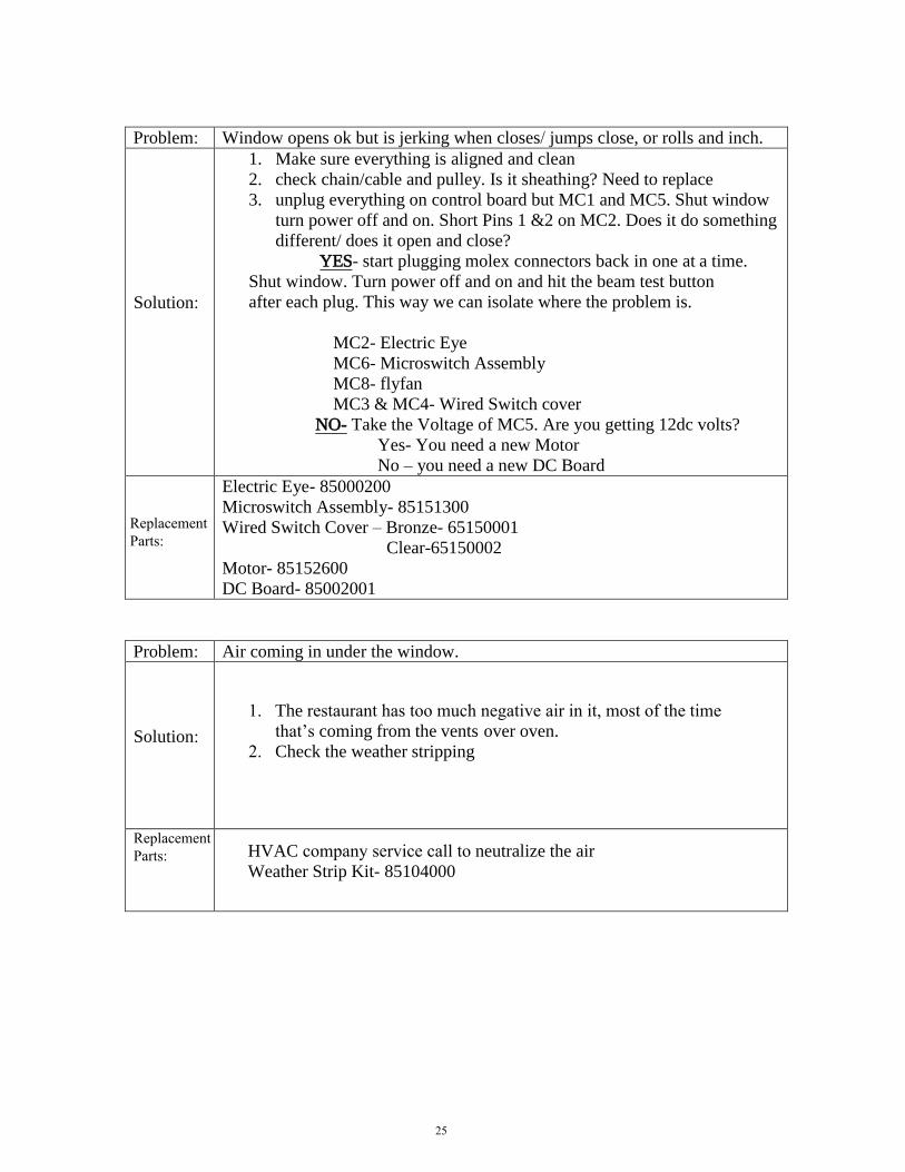
Problem: Window opens ok but is jerking when closes/ jumps close, or rolls and inch.
Solution:
1. Make sure everything is aligned and clean
2. check chain/cable and pulley. Is it sheathing? Need to replace
3. unplug everything on control board but MC1 and MC5. Shut window
turn power off and on. Short Pins 1 &2 on MC2. Does it do something
different/ does it open and close?
YES- start plugging molex connectors back in one at a time.
Shut window. Turn power off and on and hit the beam test button
after each plug. This way we can isolate where the problem is.
MC2- Electric Eye
MC6- Microswitch Assembly
MC8- flyfan
MC3 & MC4- Wired Switch cover
NO- Take the Voltage of MC5. Are you getting 12dc volts?
Yes- You need a new Motor
No – you need a new DC Board
Replacement Parts:
Electric Eye- 85000200
Microswitch Assembly- 85151300
Wired Switch Cover – Bronze- 65150001
Clear-65150002
Motor- 85152600
DC Board- 85002001
Problem: Air coming in under the window.
Solution:1. The restaurant has too much negative air in it, most of the time
that’s coming from the vents over oven.
2. Check the weather stripping
Replacement Parts: HVAC company service call to neutralize the air
Weather Strip Kit- 85104000
25

Problem: Door opens fine and closes ok but stops about an inch short
Solution:1. Check to make sure door is not dragging/ or there is a blockage
2. take header cover off and pull down on cable to release some tension
in the spring.
3. turn blue dial on control board counter clockwise all the way to reduce
amp draw- if applicable
Replacement Parts:
Problem: Window is opening, then stays open.
Solution:
The electric eye is not getting its signal back to itself.
Check if reflector is still there.
Check if reflector and eye are lined up
Adjust electric eye by taking off bracket (make sure there isn’t dirt or
grim on lens). Screw eye tight
Replacement Parts:
26

27
Parts Lists
Common Parts (Description/Part Number) Description Part Number Notes
Bracket – Handle - Manual 85002600 Door Handle Kit including all parts needed
Cable & Chain Assy 85153600 Dome - Acrylic Atrium - Brz 85000601 (Bronze Caulk) Dome - Acrylic Atrium - Clr 85000602 (Gray Caulk) Door Assy - Left Br Call for part #
Door Assy - Left Cl Call for part # Door Assy - Right Br Call for part # Door Assy - Right Cl Call for part #
Electric Eye / Reflector Replacement Kit
85000200 Waist level operation
Electric Eye w/housing 85099000 Handle Kit – Manual Release 85002600 Hanging Hardware Kit 85183400 One set to mount and adjust one door
Housing - Electric eye 00650929
Latch - Lock-Dead Vertical Position
85004200
Latch - Thumb Turn - Long - 85004500 Latch Catch Assy 85152100
Motor & Sprocket Assy 85152600 Power Supply - 120V Call for # Provide Serial #
Pulley - Kilrol (cable) 20200142 Slide Replacement Kit 85000100 Solenoid & Hook Assy R/L 85150510 R/L Style Only In the Bi-Part windows
Spring & Ball Knob Kit 85000300 3 in sets in each kit Spring - Ext (Chain & Cable) 20060025 Striker - Sensor 65151101
Switch - Eye - Retrofit Kit 84000300 Switch - Rocker 20110214 (for PCBA Cover) 8/99 to after 2/27/02 Switch Assy - Micro 85151300
Universal Control Board 85002001

28
Complete Parts List (Description/Part Number) Description Part Number Notes
Bracket - Cable Clamp 95151001
Bracket - Solenoid 95150301 Bracket - Solenoid - 65150301 w/Bracket - Order 65150501
Bumper - 1x1 w/blk Lvl 40010003 Bumper - w/washer Gry 40010023 Cable & Chain Assy 85153600
Cable Assembly - Auto Latch 20112141 (Solenoid). ( Electric)
Cable Assembly - BEA Sensor (Electric)
20112148
Cable Assembly - Eye 20112143 (Waist High) (Electric) Cable Assembly - Motor 20112144 (Electric)
Cable Assembly - Power 20112142 (Electric) Cable Assembly - Sensor 20112147 Bi-Parting Units (Electric) Caulk - Silicone - Aluminum 80050029 8oz Tube
Caulk - Silicone - Bronze 80050020 8oz Tube Caulk - Silicone - Clear 80050021 8oz Tube Channel - Rubber Glass 65028601
Channel - Slide 65130301 (Housing Slide) Clamp - Cable 95150900 Cover - Front 65149601 - (10-1/2") New BronzeCover - Front 65149602 - (10-1/2") New Clear
Cover - Motor 65152201 Cover - Slide - Manual - Brz 65163201 (BO-10 Manual) Cover - Slide - Manual - Clr 65163202 (BO-10 Manual)
Cover - Slide Channel - Brz 65151801 (BO-10 Electric) Cover - Slide Channel - Clr 65151802 (BO-10 Electric) Cover - Wired PCBA -Brz 65150001
Cover - Wired PCBA -Clr 65150002 Dome - Acrylic Atrium - Brz 85000601 (Bronze Caulk) Dome - Acrylic Atrium - Clr 85000602 (Gray Caulk)
Door Assy - Left Br Call for Part # Door Assy - Left Cl Call for Part # Door Assy - Right Br Call for Part #
Door Assy - Right Cl Call for Part # Electric Eye / Reflector Kit 85000200 Waist level operation - Repl Electric Eye w/housing 85099000

29
Description Part Number Notes Fuse - .250 AMP 20110524
Guide Kit - Door 85003500 Contains guides for both doors.
Handle Kit – Manual 85002600 BO-10M Hanging Hardware Kit 85183400 (Adj. Nut) (2) Hook - S 20240016
Housing - Electric eye 00650929 Latch - Lock-Dead Vertical Position
85004200 After 2/97
Latch - Thumb Turn - Long - 85004500 After 2/97 Latch Catch Assy 85152100
Latch Spring 00650269 Motor & Clutch Assy 85152600 Nut - "J" - Repl Kit 85078900 Nut - Well 10300007 Panel - Left Side 65149501 (10-1/2") New Style Bronze
Panel - Left Side 65149503 (10-1/2") New Style Clear Panel - Right Side 65149502 (10-1/2") New Style Bronze Panel - Right Side 65149504 (10-1/2") New Style Clear
Power Supply - 120V Cable Drive
Call for # Provide Serial #
Power Supply - 220 Cable Drive - Int'l
Call for # Provide Serial #
Pulley - Kilrol (cable) 20200142 Receptacle - Power 20110241
Reflector - Mini Call for Part # Reinforcement Angle 95119900 Rivet - Bearing Slides - Long Shank
10180010
Rivet - Door Guide 10180024
Rivet - Pop 10180009 Screw 10010061 Screw - Motor to Bracket 10010039
Screw - PCB Cover 10010033 Screw for Cable Clamp 10010026 Screw for inside cover - sensor striker
10010114

30
Description Part Number Notes Slide Replacement Kit 85000100
Solenoid & Hook Assy R/L 85150510 Spring & Ball Knob Kit 85000300 (3 ea. kit) - Repl Spring - Ext (Chain & Cable) 20060025 Standoff - 1/4 OD Hex 20110283 x m.f 6-32 THRD (Electric) Striker - Sensor 65151101
Switch - Eye - Retrofit Kit 84000300 Switch - Micro 20110281
Switch - Rocker 20110214 (for PCBA Cover) 8/99 to after 2/27/02 Switch Assy - Micro 85151300 Template - Drill - Door Slide 65134401
Universal Control Board 85002001
Washer 10230017 Washer - Flat (Electric) 10230108 Weather Strip Kit 85104000

31
Drawings Exploded Views
Part Number If Applicable
Description Page
N/A Header Assembly (Automatic) – Exploded View
30
N/A Header Assembly (Manual) – Exploded View
30
N/A Door and Slide Channel – Exploded View 31
85178200 Motor 31
85150510 Solenoid and Hook Assembly 31
N/A Window Assembly (Less Doors and Header)
Exploded View
32
Schematics
Part Number If Applicable
Description Page
N/A Electrical Schematic 33
N/A Wiring Layout (New Style PCB) 34
N/A Wiring Layout (Old Style PCB) 35
N/A Electric Eye Wiring 36

32
1
5
6
8
15
1011
12
85152100
KIT Part #
4
79 13
16
14
1A
9A
BO-10 MANUAL/SELF CLOSE & ELECTRIC
HEADER ASSEMBLY EXPLODED VIEW
17
BO-10E Header Parts Listing
REF
ID #
PART
NUMBER DESCRIPTION
REF
ID #
PART
NUMBER DESCRIPTION
1 85000100 Door Slide Kit ( 2 Slide
Channels)
10 85150510 Solenoid and Hook Assy
4 85152700 Clutch Assy 11 95151001 Cable Clamp Bracket
5 85152600 Motor & Sprocket Assy 12 95150900 Cable Clamp
6 20110281 Micro switch 13/14 85152100 (Handle and Bracket in a Kit)
7 85151300 Micro switch Assy 15 65151101 Striker Plate (Sensor)
8 20200142 Kilrol Pulley 16 20060025 Tension Spring
9 85153600 Cable and Chain Assy
BO-10 Manual & Self Close Header Parts Listing
REF
ID #
PART
NUMBER DESCRIPTION
REF
ID #
PART
NUMBER DESCRIPTION
1A 85000150 Door TRACK Kit 12 95150900 Cable Clamp
8 20200142 Kilrol Pulley 16 20060025 Extension Spring
9A 85153700 SC Cable Assembly PVC 17 95151700 Cable Connector Bracket
11A 95151300 SC Cable Clamp Bracket
33
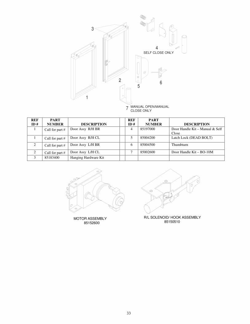
3
1
2 65
4
7 MANUAL OPEN/MANUAL
CLOSE ONLY
SELF CLOSE ONLY
REF
ID #
PART
NUMBER DESCRIPTION
REF
ID #
PART
NUMBER DESCRIPTION
1 Call for part # Door Assy R/H BR 4 85197000 Door Handle Kit – Manual & Self
Close
1 Call for part # Door Assy R/H CL 5 85004200 Latch Lock (DEAD BOLT)
2 Call for part # Door Assy L/H BR 6 85004500 Thumbturn
2 Call for part # Door Assy L/H CL 7 85002600 Door Handle Kit – BO-10M
3 85183400 Hanging Hardware Kit
MOTOR ASSEMBLY85152600
R/L SOLENOID/ HOOK ASSEMBLY85150510
KLG
Line
KLG
Line
KLG
Pencil

34
REF
ID #
PART
NUMBER DESCRIPTION
REF
ID #
PART
NUMBER DESCRIPTION
1 85000601 Dome Atrium - BR 5 65149501 Side Panel – L/H
10-1/2” BR -New
1 85000602 Dome Atrium - CL 5 65149503 Side Panel – L/H
10-1/2” CL -New
2 65149601 Front Cover – BR
10 1/2” New Style
65152201 Motor Cover
2 65149602 Front Cover – CL
10 1/2” New Style
7 85002001 Universal Control Board
4 65149502 Side Panel – R/H 10-1/2” BR -New
8 65150001 Cover – Wired
PCBA
4 65149504 Side Panel – R/H 10-1/2” CL -New
4
5
6
6
78

35

36

37

38
ELECTRIC EYE
WIRING DIAGRAM
TOGETHER WITH RED WIRE
PINK & BLUE CONNECTED
DESIGN BY:
DATE:
DRAWN BY:
DATE:
MATERIAL:
GAUGE:
USED IN PRODUCTS:
REVISION:
REVISION DATE:
MATERIAL SPEC:
DESCRIPTION:
PART. NO.:
LATEST REVISION NOT E:
WORK TO DIMENSIONS-DO NOT SCALE
XXXX TOL. NOT REQ'D
TOL. CLASS ± .030
TOL. UNLESS SPECIFIED
ANGULAR TOL. ± 1° 800-621-5045 630-876-7766 Fax 63 0-876-7767
R
1815 Arthur Drive West Chicago, IL
WAIST HIGH BEAM BREAK
OMRON ELECTRIC EYESC
11/08/05
SC
11/08/05
OR
11/8/05
BLUE
BLACK
BROWNBROWN
BLACK
BLUE
ELECTRIC EYE
SENSOR
BLACK
WHITE
REDPINK
BROWN
BLACK
BLUE
SENSOR
ELECTRIC EYE
PINK PINK

39
Appendix A
Adjusting or Re-hanging the Doors
The distance of the door(s) above the mullion or counter top is adjusted by turning the eccentric nuts
located in the corners at the top of each door. (See figure 11 – page 16) The exploded view of the
assembly is shown in Figure 1 below.
When a door has dropped, such that it impedes the movement of the doors, it is necessary to re-
adjust both doors to a given distance above the counter top. This is accomplished by loosening the
two Locking / Eccentric Nut combinations at the top of each door. Loosening the small locking nuts
allows both doors to drop down and rest on the counter top.
Slide the doors inward to the closed position and lock using the night lock. Insert two shims about
0.100” in thickness under each door. One at each end of the doors is suggested. A standard coffee
stir or a tongue depressor is a bout 0.100” thick. This allows the doors to set at a preset distance off
the counter top.
Starting with one of the Locking / Eccentric Nut combinations turn the eccentric nut with until you
feel resistance and/or notice that the door is beginning to rise. Keeping the eccentric nut in that
position, tighten the locking nut down to approximately 30 lbs/in2 of torque.
Repeat the above step for each of the remaining Locking / Eccentric Nut combinations. Remove the
shims. The doors should now be at the proper height as well as being square with each other.

Ready Access, 1815 Arthur Drive, West Chicago, Illinois 60185, Tel: 630-876-7766, Tel: 800-621-5045 Fax: 630-876-7767, Email: [email protected], Website: www.ready-access.com
40BO-10 INSTALLATION SERVICE OPERATIONS MANUAL 02/22/17