Self Balancing Transportation Platform (A.K.A. Magic Plank) Report (Super Duper Complete...
109
Magic Plank Senior Design - Group 2 1 Senior Design 1 Group 2 Self Balancing Transportation Platform (A.K.A. Magic Plank) Stephen Colby Fraser II Brian Jacobs Kenneth Santiago Jr.
Transcript of Self Balancing Transportation Platform (A.K.A. Magic Plank) Report (Super Duper Complete...
Magic Plank Senior Design - Group 2
1
Senior Design 1
Group 2
Self Balancing Transportation Platform
(A.K.A. Magic Plank)
Stephen Colby Fraser II
Brian Jacobs
Kenneth Santiago Jr.

Magic Plank Senior Design - Group 2
2
Table of Contents
1. Executive Summary................................................................................................................. 4
2. Project Description................................................................................................................... 5
2.1. Motivation ........................................................................................................................................ 5
2.2. Objectives, Goals, and Milestones .............................................................................................. 6
3. Initial Research....................................................................................................................... 10
3.1. Robotics Club ................................................................................................................................ 10
3.2. Skycraft .......................................................................................................................................... 12
3.3. Initial Research of Coding Implementation ............................................................................... 13
3.4. Power Supply ................................................................................................................................ 15
3.5. Steering Implementation ............................................................................................................. 20
3.6. Switching Voltage Regulator ....................................................................................................... 23
4. Prototype ................................................................................................................................. 25
4.1. Prototype Test Environment ....................................................................................................... 25
4.1.1. Test Environment ..................................................................................................... 25
4.1.2. Test Goals ................................................................................................................. 25
4.1.3. Test Stages ............................................................................................................... 26
4.1.4. Test Data and Expectations ................................................................................... 28
4.1.5. Test Conclusion ........................................................................................................ 28
4.2. Hardware Selection ...................................................................................................................... 28
4.2.1. IMU (Inertial Measurement Unit) ............................................................................ 28
4.2.2. Motor Controller ........................................................................................................ 30
4.2.3. Microcontroller .......................................................................................................... 31
4.3. Hardware Implementation ........................................................................................................... 32
4.3.1. Remote Control ........................................................................................................ 32
4.3.2. IMU ............................................................................................................................. 40
4.4. Software Prototyping .................................................................................................................... 41
4.4.1. Using Bluetooth with a Wiimote ............................................................................. 41
4.4.2. Using the Motor Controller ...................................................................................... 45

Magic Plank Senior Design - Group 2
3
4.5. Prototype Implementation ........................................................................................................... 46
5. Final Implementation ............................................................................................................. 51
5.1. Hardware Design .......................................................................................................................... 51
5.1.1. Circuit Design ............................................................................................................ 51
5.1.2. Motor Controller: Sabertooth 2x25 ........................................................................ 58
5.1.3. Body Design .............................................................................................................. 59
5.2. Software System: Overview ........................................................................................................ 61
5.2.1. Operational Concepts: Needs, Scenarios, Limitations, and Risks ................... 61
5.2.2. Project Management ................................................................................................ 62
5.2.3. Software Architecture and Design Issues ............................................................ 63
5.2.4. Development Environment and Hardware Interfacing ....................................... 65
5.3. Software Design ........................................................................................................................... 66
5.3.1. Motor Controller ........................................................................................................ 66
5.3.2. IMU – Raw Data Fetching ....................................................................................... 68
5.3.3. IMU – Raw Data Processing .................................................................................. 72
5.3.4. RC Coding Implementation .................................................................................... 74
5.3.5. Top Level – PID Control .......................................................................................... 89
5.4. Final Parts Selection .................................................................................................................... 91
5.4.1. Platform Materials .................................................................................................... 91
5.4.2. Motors ........................................................................................................................ 96
5.4.3. Wheels ....................................................................................................................... 97
5.4.4. Chain .......................................................................................................................... 98
5.4.5. Power Supply ............................................................................................................ 98
6. Bill of Materials ..................................................................................................................... 101
6.1. Initial Design Cost Estimates .................................................................................................... 101
6.2. Prototype Bill of Materials ......................................................................................................... 102
6.3. Final Design Bill of Materials .................................................................................................... 103
Works Cited ............................................................................................................................... 105

Magic Plank Senior Design - Group 2
4
1. Executive Summary This document details plans for a two wheeled self balancing transportation platform. Inspiration for the project comes from Segway’s line of Personal Transporters. There is something compelling about a personal transportation vehicle that can balance itself on just two wheels without any sort of stabilization mechanism other than the motors themselves. While the concept itself is fascinating, a Segway Personal Transporter can cost thousands of dollars, so the foremost strategic part of this project is to make something similar but at a significantly lower price range.
Development of this project led to some interesting conclusions. Originally, the plan was to make a transporter in the traditional manner of the Segway PT: front facing platform with a scooter-like steering column, but after some research on interesting control methods, an innovative steering solution was reached. This balancing platform’s steering control is completely wirelessly via Bluetooth control from the Nintendo Wii wireless remote controller. Handling a bulky and awkward steering column is replaced by an intuitive control scheme using a largely familiar console game controller. Since the steering column is removed, the orientation of the platform is altered from the traditional front-facing design to a side-facing design where the driver leans side to side in order to move, much like riding a skateboard. This design set this platform apart from other self balancing platforms, both significantly reducing the price of the design and giving the platform a unique look and feel.
Features:
Two-Wheeled Balancing
Bluetooth Navigation System
Unique Look and Feel
Intuitive Control
Affordable
This design is done to prove that anyone, given enough time, enough research, and enough determination, can make their own self balancing transporter at a fraction of the cost of commercial products.

Magic Plank Senior Design - Group 2
5
2. Project Description
2.1. Motivation The primary motivation for this senior design project comes from the intended nature of engineering and implementing a challenging, yet feasible and rewarding senior design project. Each senior has individually spent many hours researching various previous senior design projects from various universities across the nation. After drawing conclusive individual research, several meetings were scheduled and further discussed the various multitude of senior design projects individually researched; a mutual concern was shared, that there appeared to be a pattern of senior design projects being done across the nation: alternative power supply solutions, robots, motion capture, and imaging processing to name a few. The main goal of this project was to be very unique, something that has not been explored yet; what this senior design project has to offer is distinctiveness and a diverse set of challenges, thus making a very intriguing conversational topic with fellow engineers or with prospective employers. Furthermore, a two wheeled balancing platform is completely impractical when compared to a three or four wheel platform; therefore presenting an impeccable challenge and a rewarding senior design project before graduating UCF’s College of Computer Science and Engineering. One highly appealing aspect of designing and creating a two wheeled balancing platform, is in its self, very unique and distinguishing; therefore, leading this senior design group to believe that this may be the first group at UCF’s College of Computer Science and Engineering to actually engineer and implement this two wheeled balancing platform. It is strongly believed that future prospective employers are going to want engineers who are able to approach a problem outside the normal constraints of problem solving. This particular creative design thinking is the way complicated tribulations are solved and new innovative technological advancements are produced. This senior design project is an excellent way to become distinguished from other more common fields of research such as robotic or image processing. Engineering and implementing this two wheeled balancing platform provides the perfect amount of challenge for four seniors in the College of Computer Science and Engineering; furthermore, the high level of complexity involved will inspire zeal and eagerness to research and work on such a significant senior design project. It is helpful to have previous experience with the electronic hardware and understanding how the different communication busses talk to one another. An important set of skills would prove to be invaluable especially when dealing with the microcontroller and motor controller systems. The quandary can be surpassed with expressed and demonstrated knowledge in adjusting motor output via hall sensors and back electromotive force; furthermore, it is pertinent to be able to identify and make the necessary adjustments to the motors.

Magic Plank Senior Design - Group 2
6
There is a very high amount of expectation and a very positive forward thinking of how this senior design project will turn out. However, it is understandable that this project will not be easy; this project will be a worthy challenge and will test the knowledge base and understanding to the limit. It has been discussed in immense detail, and recognized that this is new and unexplored territory. Nevertheless, it still pays to have persistence to push forward with the current engineering and implementation. No matter the challenge and obstacle that will be faced during this senior design project, perseverance will lead through to completion.
2.2. Objectives, Goals, and Milestones This senior design group has set very concise objectives and goals; it will serve for the betterment to insure each step processed is deliberate and tangible. The outlook is to be able to build upon each step while making as little adjustment as possible to each previous objective and goal. This will allow for a productive and efficient use of research and man power. The first objective set out is to have the microcontroller operating. Microcontroller work involves understanding the pin configurations of the microcontroller, setting up a working development environment, working cross compiler, and configuring the correct libraries for the microcontroller. Once basic configuration is complete, the device must be able to configure on multiple platforms, but at the same time remain consistent between the different platforms via a centralized code base from which to refer. After, the first goal is met, the microcontroller has to be capable of responding to test programs, and it is affirmatively known of how to continue development. The second goal is to identify the correct pin connections needed for all the peripheral hardware to communicate with the microcontroller. Establishing lines of communication with the correct hardware pin addresses will allow for easy identification on how each individual piece of hardware will transmit and process data to and from the microcontroller. Equally important is the establishment of a power supply to each electronic component.
From the completion of first and second objective, the first milestone status is accomplished. The first milestone after guaranteeing communication with the microcontroller hardware pin addresses is to build the complete circuit consisting of the inertial measurement/moment unit, motor controller, and the power supply. Here it is tested for proper power supply distribution and make the fine calibrations to insure peak performance and efficiency, while at the same time safeguarding against any potential power surges that could damage one of the valuable electrical components, such as using avalanche diodes for surge protection, or a potential power over draw from any of the electrical components. Any one of the two would most certainly cause irreversible damage to the power supply. Moreover, authentication can process through the Arduino – compiler each major electronic component properly establishing a line of communication
Magic Plank Senior Design - Group 2
7
with the proper hardware address pins. Meeting this milestone will also assist with development of future software functions and methods, as well as potential hardware changes. Once the system is properly configured, the next objective is ready to be attacked, which is the beginning of software development.
The first software objective is to communicate with the motor controller via the microcontroller. This involves rudimentary control commands such as moving the motors forward, backward, and turning. This will allow for a better feel for the motor response and allow software configuration to handle a particular new wheel set. The second software objective is to obtain raw data readings from the Inertial Moment Unit (IMU) and process that data inside the microcontroller. The idea is to simply read the data and calibrate it such that the IMU outputs motion data that can then be used for the control mechanism that will ultimately balance the platform. The next objective is to integrate the processed IMU data into a rudimentary control scheme. This will show how the motors respond to the IMU’s data and how to approach the refinement of polling and calibration mechanisms in order to create a smoother control scheme.
Completion of these objectives leads to the second milestone, which is the finalization of a platform that can balance itself in a stationary position. In the second milestone, movement refinement will be in process for the motors to be more fluid and smooth through the use of software. The software will do the necessary calculations to adjust the acceleration and angle of incline at a gradual level; moreover, there is a need to possess a polished transition when decelerating or accelerating, as well as smooth transitions when increasing and decreasing angle of incline. The continuation with this project relies on the balancing control mechanisms abilities to smoothly and efficiently balance the platform, which will entail much tweaking and testing. In order to have the best product results, this device must be tested for its control scheme limitations to pinpoint which conditions are possible leading causes for a system failure. Besides checking for possible system failure, the system’s power draw will be determined on whether or not the current power solution is sufficient to progress production.
After completion of the second milestone, software development continues by incorporating navigation into the control scheme, which is the fifth objective. The first step in this process requires an established interactive method between navigation mechanism and microcontroller: what signals are sent, how the data should be interpreted, and the frequency of data obtained by the microcontroller. The goal is maintaining the platform’s balance while in a stationary position. The main mechanism planned for this control scheme utilizes communication via a Bluetooth device. Bluetooth enabled video game controllers can handle the basic commands such as: forward, backward, left and right; the current paradigm for accelerating and decelerating is by leaning, this factor will have to be figured out in a whole new method followed with a unanimous decision to control the scaled down prototype’s acceleration and deceleration. Certain Bluetooth enabled video

Magic Plank Senior Design - Group 2
8
game controllers recognize changes in pitch and yaw; controllers’ sensitivity to these types of changes can allow development towards a free flowing navigational system that will essentially enable the user to be the steering device. Each Bluetooth enabled video game controller manufacturer has released programming code which will permit users, programmers, and engineers to take advantage of the unique functionalities that each Bluetooth enabled video game controller possesses. Once, effectively harnessing the code for the particular Bluetooth enabled video game controller, only then can it be attempted to create a customized control mechanism that would work seamlessly and specifically for the designed navigational purposes. Followed by control scheme calibration for the platform’s abilities to operate smooth turns corresponding intuitively with the input device being used by the driver. After the platform can successfully turn in the stationary position, the third milestone is completed.
The next move is to the eighth objective, which is to make the platform capable of moving forward and backward. Along with the platform’s turning operations is being able to move forward or backward; which is considered a principle movement of this platform. Software governors will be coded into place as a safety measure to prevent steep angles of incline and unsafe acceleration and speeds for correction purposes in the balancing platform’s stability. If there were no governors in place, then the sudden possible corrections that platform may enact to insure its equilibrium may make the platform unstable and therefore unsafe for the user. As a result, testing and refining software based governors are desired, as well as the more complex mathematical equations to guarantee stability and equilibrium. Moreover, at this point in the objective, goals and milestones the group will further refine methods and functions of steering to gradually turn, accelerate, and decelerate the platform. Followed up with improved calibration and refinement will be done to determine when and if the status needs to be updated. Data from the inertial measurement/moment unit must be taken and compared to the current status of the balancing platform as well as the safety parameters and governors that will be instantiated in the code. In order to accurately gather data readings via proper data sampling rates, which will provide accurate output calculations that, will adjust balancing platform’s overall status. It is necessary for this platform to make gradual movements, while simultaneously providing adequate response times; indemnifying the inertial measurement/moment unit will process the proper amount of data for the platform to remain in a balanced state of equilibrium. There will be a fair amount of calibration needed in order to balance sampling rates of data to insure the smoothest and quickest physical response times. The remaining objectives seven and eight now completed and the final adjustments made to the platform, then the balancing platform will be fully functional and operational. The platform will be able, whether static or non-static positions to turn and preserve its equilibrium, including in its active state, capable of handling the different angles of incline and sufficiently readjust itself whilst the inertial measurement/moment unit detects the angles of inclination are too

Magic Plank Senior Design - Group 2
9
severe; concurrently occurring when the inertial measurement/moment unit distinguishes any instance of moving at an unsafe speed and/or the acceleration of the balancing platform is too high. When with this stage of development is finished, entails a completed fourth and final milestone: a fully functional self balancing platform.

Magic Plank Senior Design - Group 2
10
3. Initial Research Without any prior knowledge of how a self balancing platform would work, further research was required to get an idea of what was possible for this project. Supplementary investigation was necessary in projecting plausible routes to power the system, how to approach and which direction to take towards designing the software, what hardware would be proficient to run the software, how the platform would accomplish its main task of balancing, and how one could control the platform’s movement. This section details several trips and interviews that were an integral part in setting this project in motion.
3.1. Robotics Club In order to better understand how to go about building a self balancing platform, it was decided to visit UCF’s Robotics Club to gain better insight from people who have had experience with building similar projects. Accessing UCF’s Robotics Club to learn as much as possible about what motors could be utilized, what battery technologies were available, what sensors ought to be used, and any other tips about getting started. During visitation, Cassie Puklavage was interviewed, treasurer for the Robotics Club and member of the submersible team. The submersible, named Hippocamp, was designed to participate in the International RoboSub Competition by the Association for Unmanned Vehicle Systems International (AUVSI). When asked what Hippocamp used to keep its bearings underwater, Cassie pointed to a little black box fixed to the inside of the submersible. She stated that is an Inertial Measurement Unit (IMU) used to provide feedback for roll, pitch and yaw of the system through the application of gyroscopes and accelerometers packaged into a convenient single unit. For a self balancing platform such as this project, some combination of accelerometers and gyroscopes would be needed to keep the microprocessor informed as to its tilted position and make corrections accordingly.
Cassie also happened to be doing budgeting at the time and was kind enough to show the prices of some of the parts used in the Robotics Club’s vehicles. While the submersible uses a full 3-axis IMU that costs about $350, it was decisively concluded the projected self balancing platform would only need a dual-axis gyroscope that would only sense pitch and yaw. However, there was still a need of an accelerometer to measure acceleration, so considerations on either purchasing the gyroscope and accelerometer separately or obtaining a single IMU board. Cassie referred a website: Sparkfun.com, where the Robotics Club buys many of its parts. Sparkfun provides many options for IMUs, accelerometers, and gyroscopes. Some options included ST Microelectronics’s gyroscope line such as the LPY503AL gyro with breakout board for $301, or the $8 LPY5150AL bare gyro2. The gyroscope would have to be coupled with an accelerometer such as Freescale’s MMA7361 3-axis accelerometer for $83 or with breakout board for $124. Buying separate gyroscope and accelerometer boards would be a combined $42 investment or more depending upon the

Magic Plank Senior Design - Group 2
11
boards used. Another option would be to buy an IMU board such as the Analog Devices/Invensense accelerometer and gyroscope combo board for $605. The full 3-axis IMU would be more than enough and it would cost more than designing a custom-made and unique IMU from the individual accelerometer and gyroscope, so tailoring an IMU seems to be the more cost effective option. However, for prototyping, it would be advantageous to have the IMU combo board for a modular, easy to assemble, easy to debug system. Sparkfun also offers the PCB schematics for their combo boards, which is very helpful when it comes to designing couture IMUs in the future.
In addition to the IMU, Cassie informed about DC motors and motor controllers. She shared about dual-channel motor controllers, which can drive motors either completely independently or at the same time with differential drive mode, which would be the preferred method of control for the projected platform, since the motors would be moving at the same rate except for when making a turn. The Robotics Club’s currently under development ground vehicle utilizes two dual-channel RoboteQ motor controllers for the front and back wheel sets. These high end motor controllers drive 24V DC motors scrapped from a power wheelchair and run in the range of about $500 each. The self balancing platform would only need to drive two motors and would require a much less powerful motor controller. RoboteQ’s low end dual-channel motor controllers (20A) are priced at $175 each6. Over at DimensionEngineering.com, Sabertooth provides comparable 25A motor controllers for about $125 and also offers lower amperage controllers, 12A and 5A, for $80 and $60 respectively7. The lower end motors of course have a lower maximum voltage rating, so the motors chosen for the self balancing platform would determine which controllers would be adaptable.
While browsing the club’s scrap bins and examining the robots sitting in the lab, several batteries were examined that was used to power their miscellaneous vehicles. The ground vehicle was powered using a car battery, but the smaller robots were powered via lithium polymer batteries; lithium provides the lightest and most dense form of energy storage, which will be very advantageous for projects such as this; which, requires a battery to have good constant energy draw and charge, ample battery life, and a low profile. After talking with Cassie and inquiring about the different power options and the manufactures that produce them, she introduced Thunder Power RC. Thunder Power RC sells lithium polymer batteries designed and used for custom built RC vehicles. Cassie navigated through their many different battery series, and with each series she provided a brief explanation of application; Cassie did suggest one particular series that is likely be explored. The “G6 Pro Performance 45C Series Batteries,” which is described by their website as An incredible combination of performance, power and price8. It turns out that the “incredible price” part did not exactly meet budget expectations. While the price for batteries on Thunder Power RC was cheaper relative to other sites, they were still very expensive. For example, it costs $69.99 for a 2250 mAh 4-Cell/4S 14.8V battery9. This does not

Magic Plank Senior Design - Group 2
12
include the price of a charger and balancer that is needed in order to maintain proper battery health, which alone can cost upwards of $100. Considering lithium battery technology being quite pricy, having elected to explore other alternative battery technologies. The best advantage was to talk with other members of the robotics club to get their input. One member mined for knowledge designed a motor controller for the Arduino based of specifications from Arduino’s website. He designed it in CadSoft’s Eagle PCB design software, noting that the free version of Eagle PCB was very restrictive and would probably be useless on any fairly complex design. Fortunately, UCF offers computers that have the full licensed software, so access to the full version of Eagle PCB will not be an issue. This led to a conversation with some of the leaders of the robotics club, namely faculty advisor Daniel Barber and Robotics Club President Jonathan Mohlenhoff. They were informed of the intent to design a Segway-like balancing platform, which was met with some concern. They forewarned that, while designing a balancing platform was a solid concept, there were a couple major problems with the idea. First, the ability to carry human weight was a mechanical engineering problem rather than an electrical or computer engineering problem. Dealing with the ability to support 200 or more pounds is a design problem in and of itself, which distracts from the computer and electrical engineering concept of sensor fusion, circuit board design, and software design. Second, the problem is not very scalable. The first major landmark is to get the vehicle to balance. If it does not balance, the project does not work. Throwing some ideas around, they seemed to think that doing a smaller scale project was a much more reasonable decision. They reasoned that it would eliminate the headache of designing a platform robust enough to carry human weight, which would also be cheaper due to smaller motors and smaller batteries. Taking this advice under consideration, it was decided that the best move forward would be to make a small prototype that would give a better idea on the feasibility of scaling up this project. Depending upon the results of the prototype, the decision to make a full scale self balancing platform will be reassessed. At the moment, it moving forward with the full scale design is still the plan.
3.2. Skycraft During research and development of this senior design project prototype for the self balancing platform, several trips were made to Skycraft Parts and Surplus, which sells a wide selection of electronic parts and miscellaneous items suitable for any hobbyist or any scale of homemade projects. The first visit to Skycraft was to initially gain ideas and look for potential items for the small scale prototype and possibly move ahead to make a purchases on some usable parts and electronics. Initial entertaining thoughts of purchasing and implementing stepper motors, which offer very deliberate and precise movements. However, controlling these stepper motors is fairly complicated and requires a completely different and unique control method altogether, or on the other hand; a counter approach adapting an alternative motor, which would be brushed Direct Current

Magic Plank Senior Design - Group 2
13
motors. Skycraft offered both motors, but the Direct Current brushed motors were cheaper, larger, and more robust.
Decisively purchasing some 6 - 12 volt Direct Current brushed motors that appeared to be suitable enough for implementation of the prototype. The motors then needed to be attached to wheels, so acquiring two sets of wheels: one set of 6 inch wheels and one set of 3.5 inch wheels. Two different wheel-set sizes were purchased for the purposes of scalability, especially when dealing with the software side of the prototype implementation. The code needs to be specifically custom engineered for each individual size wheel size, so it is imperative to isolate any dependencies on a specific wheel set so that ease switching between wheels with minimal impact to the code. In addition to motors and wheels, possible platforms on which to place the whole system were perused. There were various materials available for the platform ranging from thin stainless steel plates to acrylic squares to lexan sheets. Final results concluded with obtaining a small sheet of aluminum honeycomb, which was the best material in terms of weight versus tensile strength that surfaced. Furthermore, some quantifiable time was spent examining power supply solutions and charging solutions as well. Consequently there only seemed to be a very limited selection of batteries at the time.
After the first trip, the prototype was deemed ready for building, which is described in detail later under the prototyping section. Skycraft was visited a second time to make specific purchases after designs of the prototype was under way, most notably including a Lithium Ion battery pack, which is described further under the Power Supply subsection of this initial research section.
3.3. Initial Research of Coding Implementation Software implementation for the self balancing platform requires much research and even more testing to see what will and will not work for this project. The software development for the self balancing platform will be accomplished using the C and C++ programming languages, since it is readily apparent that higher level languages just simply do not work on the embedded level and doing the development in straight assembly is purely unmanageable. The microcontroller initially chosen for the project, Texas Instruments’ Stellaris, is an ARM Cortex-M3 based processor1, so finding an ARM compiler and development suite is the first step in the process.
The GCC and G++ compilers do compile for ARM architectures, but the compilers themselves lack libraries and development environments, so the actual compiler is relatively useless without libraries to support it. Texas Instruments provides its own software, Code Composer Studio, for development of its products. However, the software is not free, and there are other development environments to explore, such as Keil SDK, which is a set of embedded development tools for multiple ARM products. While the Keil SDK has many features for embedded development, it is a very expensive software suite that

Magic Plank Senior Design - Group 2
14
probably does not fit the budget. The cheaper alternative to Keil SDK is the Sourcery CodeBench by Mentor Graphics2, which is a full set of embedded development C/C++ development tools developed from the GCC/G++ compilers. There are several options for Sourcery CodeBench, most notably the Academic Edition for $99 and the lite edition, which is a free command line version of the core development tools. While it may not offer as much and may not be as easy to use as other products out there, the free Sourcery CodeBench lite seems to be the best decision financially.
Although the Stellaris is a powerful microcontroller with high performance and versatile functionality, configuring the development environment and getting feedback from the board is an excruciating process. Despite TI’s attempts to provide examples for code use and software development, these resources dwindle in comparison to the community support provided by Arduino, the open source prototyping platform that utilizes microcontrollers from Atmel and combines them with a powerful and easy to use Integrated Development Environment that allows the ease of coding and debugging the system. One such product in the Arduino line is the Arduino 328, which utilizes the Atmel ATmega3283. The smaller 32 pin ATmega328 AVR RISC-based microcontroller may be a step down from the mighty 100 pin Stellaris ARM microcontroller, but from a software development perspective, the ATmega series provides free and easy to use development tools that have seemingly endless amounts of documentation and community support. Developing on ATmega processors with the Arduino boot loader installed is intentionally easy and takes the pain out of configuring a device. Under the Microcontroller subsection of the Prototyping section later in this document, details further decisions regarding decisions in choosing between the Stellaris and ATmega microprocessors for full scale development by experimenting with software development in both prototyping platforms.
Development environments aside, the software development really boils down to the programming techniques used on this project. Creating a balancing platform with the use of a gyroscope requires that the program keep track of the gyroscope’s orientation and attempt to keep the gyroscope level. The conventional motor control method for keeping sensor readings within a certain threshold is the proportional integral derivative, or PID, control loop. PID control typically provides smooth control with minimal overshoot on corrective action. Although there are easier control methods like bang-bang, proportional (P), and Proportional-Derivative (PD), taking the extra time to factor in a smooth integral will be the best payoff for a smooth and efficient system.
Other areas of concern besides the main PID control loop are obtaining sensor data from the gyroscopes and accelerometers and communicating with the motor controller. Analog output accelerometers and gyroscopes communicate with a Pulse-Width Modulation (PWM) signal, which most microcontrollers support. Digital output accelerometers and gyroscopes, such as the ones found on
Magic Plank Senior Design - Group 2
15
sparkfun.com, communicate using standard I2C protocol. There are a few different ways to communicate with motor controllers, which can be categorized by either analog or digital input. Analog input is done via PWM. Digital input can be done a couple ways. The first is by simulating an R/C signal that sets the speed and direction of the motor until specified at another time. The second is to use serial data to communicate the speed and direction of the motors. The main advantage to using serial data is that the microcontroller can communicate with the motor controller with just one serial port. In the prototyping development section, different ways of controlling the motor controller were explored and make use of what is available on the motor controller that was purchased.
3.4. Power Supply Researching and designing the power supply for this senior design project took serious discussions and considerations on what exactly to look for as far as how to layout the power supply to affect the rest of the system. Power supply was discussed and considered the many different types of power supplies, what types of power supplies would be more common and readily available, and the what exact voltage and milliamp hours needed. Furthermore, with each different power supply type, different distinguishable physical specifications followed suit. Most important of these physical specifications are the mass and size; since the senior design project chosen addresses the “Inverted Pendulum Problem,” mass and size could make the calculations and eventual building relatively simple, or more complicated with more equations and counter weights to compensate for the increased mass and size of the power supply. Since this project is funded by personal means, finding power supply solutions that are readily available, simple to implement, cost effective, and easily replaceable a top priority. In the midst of researching the most common power supplies currently available; the most common are nickel – cadmium (NaCd), nickel – metal hydride (NiMH), lithium – ion (Li – ion), and lithium – ion polymer (Li – poly). Theses power supplies are listed, in order, from the most size, mass, and cost effective to least size, mass, and cost inefficiency. After reviewing all physical specifications of each different power supply, nickel-cadmium power supply solutions were by far the cheapest choice, but unfortunately these power supplies also have the most mass and size; additionally, for these particular power supply solution, nickel-cadmium is a power supply that is comprised of a heavy metal. By their nature, heavy metals are very toxic and require special care for using this particular power supply solution; moreover due to the general composition of the nickel-cadmium power supply, it suffers from the effect know as the “memory effect.” This means that as the nickel – cadmium power supply becomes older it “forgets” its charge, and therefore drains much quicker; unfortunately they maintenance to prevent this is not simple, and could either be damaging to the power supply and/or a very involved process1. Needless to say, a nickel – cadmium power supply solution

Magic Plank Senior Design - Group 2
16
disadvantages, physical specifications and built in hardware flaws make nickel – cadmium a less than ideal power supply solution; therefore it is best to no longer pursuing this particular power supply solution as a viable choice. Advantages:
Cheapest Power Supply Currently Available on Market Disadvantages:
Most Mass and Size
Must Be Completely Discharged before Recharging
Comprised of a Heavy Metal
Suffers from “Memory Effect” A lot more focus was poured into research and design theory with nickel – metal hydride power supply solutions; nickel – metal hydride is currently replacing nickel – cadmium power supply solutions, for nickel – metal hydride is not manufactured with any heavy metals, therefore making handling and usage of these power supplies safer to handle and use. Moreover, nickel – metal hydride power supply solutions do not suffer from the “memory effect,” and as a result nickel – metal hydride power supply solution do not have to fully discharged, which in the cause of a nickel – cadmium power supply solution would damage the power supply. Instead nickel – metal hydride power supplies can be used and charged without any worry of negative effects, affecting the overall health of the power supply solution2. In addition, the way the power supply is manufactured allows the nickel metal hydride power supply to charge rapidly and effective, once it has completed it charge cycle it enters a trickle charge state; as a result this allows the power supply solution to go longer periods of time without a charge, again with a nickel – cadmium power supply this would cause negative effects to the overall health of the power supply3. Advantages:
Good Balance Between Mass and Size
Cost Effective
Can be Charged Regardless of Charge Level
Provides More Power Than Nickel – Cadmium Supplies Disadvantages:
Slightly Less Efficient Than Nickel – Cadmium
Has a Risk of Becoming Overcharged
Less Number of Charge Cycle Times Than Nickel - Cadmium Another major focus of research and design theory is with lithium – ion power supply; lithium – ion is one of the most popular and widely used and easily acquirable in many different configurations. Lithium – ion power supply solutions are low maintenance, compared to both nickel – cadmium and nickel – metal

Magic Plank Senior Design - Group 2
17
hydride power supply solutions. In addition, the way lithium – ion power supplies are manufactured they provide little impact in the environment; moreover lithium – ion power supplies have typically twice the energy density of nickel – cadmium, nickel – metal hydride power supply solutions share the same power densities of lithium – ion. Furthermore, the self – discharge is less than half compared with nickel – cadmium; therefore making lithium – ion power supply solutions more suited to modern electronics4. Over all lithium power supply solutions have smaller sizes and masses; this due to the inherent nature of lithium being know as a light metal and highly reactive, being highly reactive means that the lithium ions will store large amounts of energy; and coupled with carbon, allows lithium – ion produced in a very light and compact nature5. As a result lithium – ion power supply solutions are perfect choice for high energy draw electronic systems with a very low impact on power supply profile and weight. Advantages:
Small Mass and Size
Twice the Energy Density of Nickel – Cadmium and Nickel – Metal Hydride
High Energy Efficiency Disadvantages:
Dangerous, Overcharging or Over Depleting May Cause Damage
Expensive Along with lithium – ion power supply research and design theory, the group noticed another lithium – ion polymer power supply solutions; lithium – ion polymer power supply solutions are the newest type of power supply solutions that entered the market of portable power supplies. Lithium – ion polymer power supply solutions act very similar to lithium – ion as far as operation and application; however, lithium – ion polymer power supply solutions are indeed a very different than lithium – ion. Lithium – ion polymer use a thin layer of plastic instead of the porous separator soaked in electrolytes, this allows the exchange of lithium ions without causing electrical conductivity4,6. Furthermore, in more commercial production of lithium – ion polymer power supply solutions gelled electrolytes are used; this eliminates the need for a metal shell around the cells. Moreover, the gelled electrolytes enhance the overall capacity of the lithium – ion polymer power supply4,6.Lithium – ion polymer power supply solutions manufacturing process is not confined by standard cell formats, coupled with the lack of a hard metal shell allows the lithium – ion polymer power solutions free form factor. The free form factor allows lithium – ion polymer power supplies to achieve profiles that resemble credit cards; cells can achieve thicknesses of one millimeter4,6. The ability to use lithium – ion polymer would provide great advantages with is extremely low impact on size and mass to the overall design; unfortunately, lithium – ion polymer power supply solutions are relatively new on

Magic Plank Senior Design - Group 2
18
the market, they are expensive and using new technology can have potential risks. Advantages:
Small Mass and Size
Very Thin Profile
Twice the Energy Density of Nickel – Cadmium and Nickel – Metal Hydride
High Energy Efficiency Disadvantages:
Dangerous, Overcharging or Over Depleting May Cause Damage
Expensive After all the initial research and design theory for the most common power supply solutions available, whittling down to a three way between nickel – metal hydride, lithium – ion, and lithium – ion polymer power supplies. Nickel – metal hydride, because this power supply solution is readily available, a well all around balance of size and mass, manufactured to be used in various applications. The group would not have any issues looking for nickel – metal hydride power supply of voltages and milliamp hours; moreover nickel – metal hydride power supply solutions are inexpensive and reasonably easy to procure replacements. Lithium – ion power supply solutions, because of very high power density couple size and mass, very low impact on mass and size to overall build and calculations, and excellent idle/self discharge; similarly, to nickel – metal hydride power supply solutions, lithium – ion power supply solutions are readily available and manufactured to be used in various applications. However, lithium - ion power supply solutions are more expensive that nickel – metal hydride; yet, coupled with all the advantages of using a lithium – ion an increase in cost is acceptable trough cost analysis. Lithium – ion polymer power supply solution, because the low profile and thin each power cell can be, the higher energy density per cell over lithium – ion power supplies, and overall enhanced capacity of lithium – ion polymer power supply solutions. Nevertheless, lithium – ion polymer carries a higher cost just like lithium – ion, and through cost analysis with all the advantages lithium polymer power supply solutions have the price per cell make this power supply a viable choice. Prior research began by looking online as the main way of purchasing and procuring necessary power supply solution. From advice given by Cassie Puklavage, a treasurer with the Robotics Club, an option looked at was Thunder Power RC as a primary choice for lithium – ion polymer power supply needs7. More specifically scrutinized at their G6 Pro Performance 45C Series LiPo Batteries. Thunder Power RC offered a very large variety to select from, and it took some time reading and analyzing all the viable power supply solutions, but after some time found TP2250-4SPP45, a 2250 milliamp hours/4 cell 14.8 volts

Magic Plank Senior Design - Group 2
19
lithium – ion power solution. This met the required specifications nicely, with extra volts for some extra breathing room. The nickel – metal hydride power supply solution was found through Lynxmotion10 via Dimension Engineering8, the same location where the motor controller was purchased9. Lynxmotion has an ample supply of nickel – metal hydride power supply solutions to choose from; however, due to current standards for manufacturing nickel – metal hydride power supplies, there is less subtle variations and more pronounced distinctions between power supply. Luckily the necessity for a power supply, is a standard variation in nickel – metal hydride power supply solutions. The BAT – 06 nickel – metal hydride power supply would provide 2800 milliamp hours/10 cell 12.0 volts of sustained power11. This nickel – metal hydride power supply would provide more than enough milliamp hours; however, since the voltage is the exact amount needed we need to double check all mathematical calculations and physical connections to verify no possibility of over draw on the nickel – metal hydride power supply. The lithium – ion power supply resolved initial intended to purchase online via eBay or Amazon; however, on one particular purchase run for parts from Skycraft12, a local store that purchases and sells parts and surplus, a quick pass through their power supply and batteries section and were pleasantly surprised to find some lithium – ion power supplies being sold. This particular lithium – ion power supply, 2400 milliamp hour 14.4 volts would provide the perfect balance power density and run life coupled with all the amazing advantages of lithium – ion power supply solutions. It would permit for more than adequate power in the initial prototype implementation and as well as the possible final design implementation, without any fear of over drawing power and damaging the lithium – ion power supply solution. After debating the advantages and disadvantages of all the power supply technologies that were explored, and satisfactorily choosing nickel – metal hydride as a preferred power supply solution. Since nickel – metal hydride is a decent middle ground of price vs size and mass performance. Nickel – metal hydride energy density ranges from 60-120 Wh/kg(12), which can be expected as a typical large supply to perform at around 70 Wh/kg. While it under performs the 110-160 Wh/kg lithium – ion power supply solutions, a typical lithium - ion power supply runs at a significantly steeper price. The TP2250-4SPP45 lithium – ion polymer power supply found at Thunder Power RC costs around $70; moreover, this price does not include the charger, which would cost another $100. Comparing this to the BAT – 06 nickel – metal hydride power supply with $25 charger found at Lynxmotion, nickel – metal hydride is the clear winner in the price battle. However, while searching for parts at Skycraft, taking a quick pass through their power supply and batteries section and were pleasantly surprised to find a few Li-ion power supplies being sold. The group acquired a 2400 milliamp hour 14.4 volts power supply, charger, and appropriate connective wiring for the

Magic Plank Senior Design - Group 2
20
combined cost of around $15, a price that is impossible to ask from anything but a surplus store. While being fortunate enough to obtain this rare find and intend to use this battery at least in the prototyping stage, there may still be a result in buying a nickel – metal hydride power supply in the event that something happens to this battery or it is not sufficient to power the final design implementation. Table 3.4-1 provides a summarization of the researched power supplies and their properties.
Model Number
Type Cells #
Voltage V
Battery Life mAh
Price $
TP2250-4SPP45
LiPO 4 14.8 2250 $69.99
BAT-06 NiMH 10 12 2800 $39.99
CGA18650/4 Li-Ion 4 14.4 2400 $12.50
Table 3.4-1: Summarization of power supplies and properties.
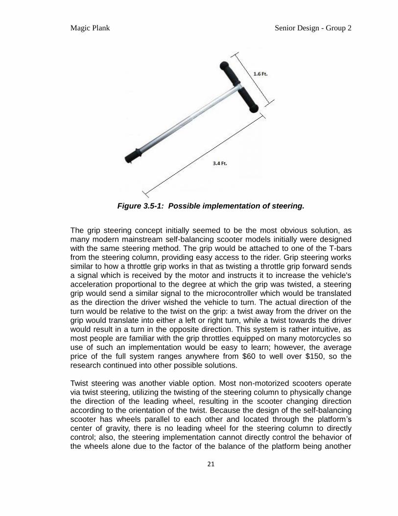
3.5. Steering Implementation In order to insure that the rider on the motorized self-balancing scooter is able to control the direction that the scooter is moving in an effective but still creative manner, several different approaches were considered to implementing the steering system. Because of the general complexity of the project being miles above that of a standard scooter, a simple implementation which would have the steering mechanism directly control either the wheels or the motor controller is simply just not plausible. It was important to make sure that the method chosen was both practical and affordable, but still had enough flare in it to make it a worthy endeavor. Another point necessary to factor in was that the steering method implemented can’t be too complex that it would overly complicate the scooter’s self-balancing design when the two algorithms are integrated together. To this end, three different methods explored to successfully implementing the scooter’s steering: grip steering, twist steering, and tilt steering. All three different implementations initially narrowed the search to include for steering would involve some modification of the self-balancing scooter’s steering column. The steering column is nearly identical to what is seen on many modern scooters, motorized or otherwise. As depicted in Figure 3.5-1 in a similar design, the steering column’s design is a general ‘T’ shape which provides grips on the upper bars to assist with the personal balancing of the rider. The actual connection of the steering column to the self-balancing scooter would vary based on the design of the selected solution to satiate steering needs.
Magic Plank Senior Design - Group 2
21
Figure 3.5-1: Possible implementation of steering.
The grip steering concept initially seemed to be the most obvious solution, as many modern mainstream self-balancing scooter models initially were designed with the same steering method. The grip would be attached to one of the T-bars from the steering column, providing easy access to the rider. Grip steering works similar to how a throttle grip works in that as twisting a throttle grip forward sends a signal which is received by the motor and instructs it to increase the vehicle's acceleration proportional to the degree at which the grip was twisted, a steering grip would send a similar signal to the microcontroller which would be translated as the direction the driver wished the vehicle to turn. The actual direction of the turn would be relative to the twist on the grip: a twist away from the driver on the grip would translate into either a left or right turn, while a twist towards the driver would result in a turn in the opposite direction. This system is rather intuitive, as most people are familiar with the grip throttles equipped on many motorcycles so use of such an implementation would be easy to learn; however, the average price of the full system ranges anywhere from $60 to well over $150, so the research continued into other possible solutions. Twist steering was another viable option. Most non-motorized scooters operate via twist steering, utilizing the twisting of the steering column to physically change the direction of the leading wheel, resulting in the scooter changing direction according to the orientation of the twist. Because the design of the self-balancing scooter has wheels parallel to each other and located through the platform’s center of gravity, there is no leading wheel for the steering column to directly control; also, the steering implementation cannot directly control the behavior of the wheels alone due to the factor of the balance of the platform being another

Magic Plank Senior Design - Group 2
22
variable that the microcontroller must account for and be able to alter the steering and throttle accordingly for. While it is possible utilizing the gyroscope on board the Inertial Measurement Unit to detect the twist of the steering column and report that information to the Arduino Atmel processor development board in order to communicate the desired steering directions, this path seemed rather troublesome for system that was well overdone. It is a possible solution to our steering initiative as it is both cheap and effective, but it was decided to continue searching to see if something fit our design a bit better. Tilt steering is the system used by the more recent designs of balancing scooters. This design, just like the previous two, utilizes a steering column which will be used to transmit the driver’s steering decisions. The way the driver of the self-balancing scooter would operate the steering in this design is similar to that of the twist steering design. Both tilt steering and twist steering involve the physical manipulation of the steering column rather than through some other electronic medium such as the grip steering; however, unlike with twist steering, tilt steering operates by having the steering column able to pivot to the left and right, affectively allowing the user to “tilt” the steering column in the direction that he/she would have the self-balancing scooter turn. Implementing the steering column’s ability to pivot left and right is as simple as attaching it to a stationary joint mounted to the platform which the driver will be standing on. With the steering column correctly attached to the mount joint, the task of communicating the direction that the column has been tilted is as simple as physically attaching the Inertial Measurement Unit to the steering column. Because the gyroscope on the Inertial Measurement Unit is capable of detecting and communicating three degrees of movement, it would be able to detect both the movement of the steering column and the change in the tilt of the standing platform, as the joint that the steering column is attached to is mounted directly to the platform; because of this, any change in the tilt of the standing platform directly affects the tilt of the steering column. This implementation is not only cheap and plausible but, because it utilizes the gyroscope aboard the Inertial Measurement Unit which is already reading information from the tilt of the standing platform, coding it to interpret the data it receives will be a relatively simple task. Because of these factors, tilt steering was the steering system that was initially decided on to implement on this project. Upon researching the possible steering implementations for prototype balancing board, however, stumbling upon the idea of simply using the same steering system for the full-scale project as was done for the prototype. Doing so would not only be less expensive, as it would not require purchasing any additional parts or engineer any new type of pivot devices, but permitting the project to have the majority of the work already completed ahead of time as implemented it with the prototype. Because the prototype’s design was to test out the core mechanics of the steering and throttle of the full-scale project, the transition from
Magic Plank Senior Design - Group 2
23
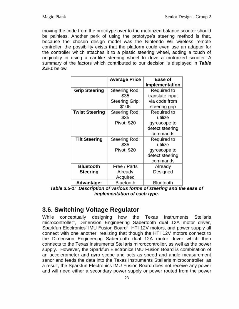
moving the code from the prototype over to the motorized balance scooter should be painless. Another perk of using the prototype’s steering method is that, because the chosen design model was the Nintendo Wii wireless remote controller, the possibility exists that the platform could even use an adapter for the controller which attaches it to a plastic steering wheel, adding a touch of originality in using a car-like steering wheel to drive a motorized scooter. A summary of the factors which contributed to our decision is displayed in Table 3.5-1 below.
Average Price Ease of Implementation
Grip Steering Steering Rod: $35
Steering Grip: $105
Required to translate input via code from steering grip
Twist Steering Steering Rod: $35
Pivot: $20
Required to utilize
gyroscope to detect steering
commands
Tilt Steering Steering Rod: $35
Pivot: $20
Required to utilize
gyroscope to detect steering
commands
Bluetooth Steering
Free / Parts Already
Acquired
Already Designed
Advantage: Bluetooth Bluetooth
Table 3.5-1: Description of various forms of steering and the ease of implementation of each type.
3.6. Switching Voltage Regulator While conceptually designing how the Texas Instruments Stellaris microcontroller1, Dimension Engineering Sabertooth dual 12A motor driver, Sparkfun Electronics’ IMU Fusion Board3, HTI 12V motors, and power supply all connect with one another; realizing that though the HTI 12V motors connect to the Dimension Engineering Sabertooth dual 12A motor driver which then connects to the Texas Instruments Stellaris mircrocontroller, as well as the power supply. However, the Sparkfun Electronics IMU Fusion Board is combination of an accelerometer and gyro scope and acts as speed and angle measurement senor and feeds the data into the Texas Instruments Stellaris microcontroller; as a result, the Sparkfun Electronics IMU Fusion Board does not receive any power and will need either a secondary power supply or power routed from the power
Magic Plank Senior Design - Group 2
24
supply, then stepped down so not to over load the Sparkfun Electronics IMU Fusion Board.
The first approach to this problem by considering to attach a second lead to the positive lead of the power supply, then using a voltage step down to reduce the input voltage to prevent overloading the Sparkfun Electronics IMU Fusion Board. Unfortunately, this particular method would have to be custom tailored for our implementation; consequently the cost and the time to research would otherwise place valuable finances and man power required for our senior design project. Therefore, as a group decision voted on to explore other options to address our current power supply and the Sparkfun Electronics IMU Fusion Board problem.
During a senior design group sessions it was suggested that additional exploration of linear voltage switches. Through a major electronics part distributor, Digi-Key Corporation, the group found LM7805CT-ND linear voltage switch. The LM7805CT-ND could take an input voltage up to 35 volts and step it down to a constant 5 volts. At first, the group thought a LM7805CT-ND switch was a possible solution to our power diversion problem; indecently, this also an inefficient solution when considering how the LM7805CT-ND takes care of the excess power from the power supply. The LM7805CT-ND takes the extra power from the power supply and using the integrated heat sink, the power is bleed off as heat. This particular solution would be an acceptable when deal with alternating current, but when using a direct current power supply, trying to save and recycle as much power as possible is a top priority.
Two of the Computer Engineers on the team, Stephen Fraser and Brian Jacobs, found that Dimension Engineering manufactures, recommends, and sells a switching voltage regulator, DE-SW050 5V 1A Switching voltage regulator6. A voltage switch acts very similar to a linear voltage, except it siphons small amounts of energy at set intervals. This allows the DE-SW050 5V 1A Switching voltage regulator to efficiently use the power from the power supply in small amounts to minimize the bleed of the excess power as heat. The DE-SW050 can handle up to 30 volts input and output a constant 5 volts. The DE-SW050 makes the perfect choice for using a Direct Current power supply, without worry of any inefficiency
Using the equation, “Power Wasted = (Input voltage – output voltage) * load current7.” The group found DE-SW050 5V 1A Switching voltage regulator to be a more efficient choice. The obvious choice was made clear to purchase the DE-SW050 5V 1A Switching voltage regulator. The initial concerns of power supply life, efficiency and over all synergy of circuit implementation are now laid to rest, and now, research and design with software can begin.

Magic Plank Senior Design - Group 2
25
4. Prototype In order to answer some pertinent questions about designing the self balancing platform, it was decided to first design a small scale prototype. This section details findings on hardware selection, high level design decisions, and software approaches to solving the problem at hand. The initial concept was to build a platform that basically resembled Segway’s line of Personal Transporters. As detailed in this section, much more than the traditional style was explored beyond the Segway’s line of PT’s front-facing orientation with scooter-like steering column. In particular, steering and acceleration mechanisms are explored in-depth with a few innovative variations on the conventional handlebar style steering mechanism. In addition to the control scheme, the hardware selection was reevaluated and re-imagined at almost every aspect of the hardware selection. From high level conceptual design to the low level hardware and software design, the group has undergone several important revisions that have helped obtain a better understanding for designing the final product. Although there are some uncertainties still looming, the prototype has answered the most important questions and gained group confidence in the final design implementation.
4.1. Prototype Test Environment
4.1.1. Test Environment
The test environment will have a UART coded specifically for the ATMEGA 328P Arduino Uno Development Board. Since this project utilizes the Bluetooth RN – 42 and have access to a laptop with Bluetooth capability. The mathematical results, from the software UART of the Arduino Uno, and positional data, from the hardware UART of the Bluetooth RN -42, will be displayed on the Bluetooth enabled laptop. At the this time documentation will be compiled and comparing both sets of data to make real time adjustments to the software, angle of incline governor, speed governor, and acceleration governor and project the change in results; additionally, determine any fine – tuning that may need to be done to the platform. The code, done in a variation of C++ will be cross – compiled loaded into the ATMEGA 328P Arduino Uno Development Board to run.
4.1.2. Test Goals
With a completed prototype implementation, testing begins entailing how the prototype could handle forced stationary movements, such as simply turning either to a clockwise motion or a counter – clockwise motion while not having to achieve true independent balance. After completion of forced stationary trials move forward to test the platform in a stationary position without any assistance to keep the plat form upright. After successfully turning the platform clockwise and counter – clockwise with any balancing assistance, the project moves forward to the second round of testing.
Magic Plank Senior Design - Group 2
26
Second round of testing consists of very similar trials, except trial runs of the platform ability to move forward and to move backward. As before, with the initial test round experimenting with the platform’s balancing assistance. Once sufficient data is gathered from the first test the balancing assistance will be removed, and test the platform’s ability to move forward and backward. During this time the group will gather test data; after completing all test data collection. The data collection will be cross referenced and any necessary calibrations will be made. The third and final test round will combine both first and second round testing; in addition, this testing round will be further evaluated for final calibrations. Spending much time in the prototype test phase will allow evaluation of very similar problems to building the final implementation. Furthermore, the test data gathered during this test phase can and will be carried on to our final implementation build.
4.1.3. Test Stages
Test one of the round one tests will test the effectiveness and responsiveness of the platforms ability to turn in a clockwise motion and in a counter – clockwise motion. During this initial test balancing assistance will be provided; this test is not to test the balancing capabilities, but the turning itself. The platform reactions to the command physically will be under observation; additionally observing the results of the UARTS to see how software is processing the data as well as the commands given to transition turns. During the observations test data will be collected, these tests assess effectiveness and responsiveness of the platform. After assessing the platform’s results, use the assessments, in fine – tuning the timing of the turns. Having the platform properly tuned is extremely important. For instance, if the platform responds to slow, it will turn in a similar manner. This sluggish response to turning commands may not provide the “First In First Out” buffer with enough data in the Inertial Measurement/Moment Unit Fusion Board for the ATMEGA 328P Arduino Development Board to process. Therefore, sending insufficient data to the motor controller will provide less than acceptable turning. Moreover, having the platform turn too fast will place to much measured data into the “First In First Out” buffer an overload the Inertial Measurement/Moment Unit Fusion Board. This will cause important measured data to drop from the buffer, and the Arduino Uno Development Board will suffer from data loss as a result of the buffer being overloaded. This in turn, will cause improper data results to be relayed through the UARTS. Once we have perfected the timing, the balancing assistance will be removed and we will perform the second test. The second test is exactly the same as the first test; we will again test the effectiveness and responsiveness of the platform as it turns in a clockwise and counter – clockwise. We will observe and gather test data and rate the effectiveness and responsiveness while the platform balances itself. With the data gathered from both tests in this stage, we will review and compare both sets of results to determine if further tuning and calibration is required.

Magic Plank Senior Design - Group 2
27
With the successful conclusion of round one tests we venture forward into second round of tests. Here we test the performance and sensitivity of the platform ability to move forward and to move backward. As before we will attach balancing assistance to record and document base test data; analyzing this data will determine if further calibration must be done. Again the platform must move and accelerate at an optimal speed for the Inertial Measurement/Moment Unit Fusion Board to measure data to store in the “First In First Out” buffer. If the platform accelerates/decelerates or moves in either direction to slow the buffer will not have take enough data readings and this would negatively affect the performance; additionally, with the buffer not having enough important packets of data the sensitivity of the platform will severely suffer causing much dismay to the user and overall performance of the platform. On the opposite side of the spectrum, if the platform sensitivity is too high, this will cause the platform to accelerate/decelerate or move in either direction to fast. As a result, too much data will be measure and therefore an overload of data will be present in the “First In First Out” buffer. Consequently, this will cause the buffer to drop important packets on measured data; this will negatively affect the performance of the platform. For example, if the platform is accelerating/decelerating too fast in either direction and the platform is at an angle of incline where correcting it could cause the platform to over correct and lose equilibrium. This would be caused because the rate at which the Inertial Measurement/Moment Unit Fusion Board is measuring data faster than the buffer is sending to the ATMEGA 328P Arduino Uno Development Board for processing. Hence, any data measured by the Inertial Measurement/Moment Unit Fusion Board will be dropped for the “First In First Out” buffer will be full. In our third and final round of testing we combine clockwise, counter – clockwise, forward and backward movements. In the previous rounds of testing, we specifically tested each individual movement with balancing assistance, documented the results, process and refine the data to make final modifications to each movement. These modifications and documented data will permit to gain the foresight and ability to assess potential problems we will face in this stage of testing as well as in our final implementation. To gather our base test data for our third and final state, we will enable balancing assistance with the platform. Here we will conduct extended maneuvers that will test both the platforms ability to turn in clockwise and counter – clockwise, as well as accelerate/decelerate forward and backward. Extended maneuvers will consist of combination of making gradual clockwise and counter – clockwise turns while moving forward and backward. Moreover, the maneuvers will also comprise of immediate clockwise and counter – clockwise turns while moving forward and moving backward. The extended maneuvers will test the modifications we have made in the previous first and second stages; additionally we document the performance of the platform when both sets of movements. Once we conclude our data documentation we will cross reference results and rate performance and
Magic Plank Senior Design - Group 2
28
responsiveness; we will make the final major calibration to software and tuning to the motors. Following the conclusions of first test of the final stage, we will remove the balancing assistance and conduct the same tests of combination of making gradual clockwise and counter – clockwise turns while moving forward and backward and immediate clockwise and counter – clockwise turns while moving forward and moving backward. During the last test we take our final documentations and refinements.
4.1.4. Test Data and Expectations
Within each stage, within each test, we record and document the results. The results are then used assist in the process of refinement and enhancement to the balancing platform. Each stage, each test will be of assisted trial and error and require multiple runs. The data gathered will provide the foresight and ability to anticipate problems that we will face with building our final implementation. Furthermore the data we gather and document can project how changing environmental variables in our software, angle of incline governor, speed governor, and acceleration governor will interact with the larger capacity electronic and physical hardware. We expect that keeping the documented test data from the prototype build will provide a great advantage come time for our final implementation.
4.1.5. Test Conclusion
The three stage processed proved to be highly effective in diagnosing and addressing both software and hardware issues of our balancing platform. Through each stage, and each tests we were able to identify a immediate problem as well as a potential problem that would arise later in the prototype tests and prototype implementation. However, the trials were not free from frustrations; we would experience having to run a state test multiple times to try narrow down a problem and multiple tests in order to test weather our solutions and corrections would work effectively. Moreover, we would find ourselves during more than one occasion solving a problem in stage test, and then having to revert back to a previous step in order to identify another problem that had arisen; as the saying goes “One step forward, two steps back.” Fortunately, we found that when faced with a situation as such that approaching the problem in a different mindset and implement a different calibration, or solution would solve both problems at the same time. From our combined experience and data collected from the various state tests’ we are confident that we are going to be able to work through the final implementation build with no fear of being ill – prepared.
4.2. Hardware Selection
4.2.1. IMU (Inertial Measurement Unit)
During development of our prototype, we have come to some conclusions for some of the individual components of our self balancing platform. Since the
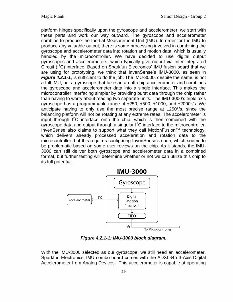
Magic Plank Senior Design - Group 2
29
platform hinges specifically upon the gyroscope and accelerometer, we start with these parts and work our way outward. The gyroscope and accelerometer combine to produce the Inertial Measurement Unit (IMU). In order for the IMU to produce any valuable output, there is some processing involved in combining the gyroscope and accelerometer data into rotation and motion data, which is usually handled by the microcontroller. We have decided to use digital output gyroscopes and accelerometers, which typically give output via Inter-Integrated Circuit (I2C) interface. Based on Sparkfun Electronics’ IMU fusion board that we are using for prototyping, we think that InvenSense’s IMU-3000, as seen in Figure 4.2.1-1, is sufficient to do the job. The IMU-3000, despite the name, is not a full IMU, but a gyroscope that takes in an off-chip accelerometer and combines the gyroscope and accelerometer data into a single interface. This makes the microcontroller interfacing simpler by providing burst data through the chip rather than having to worry about reading two separate units. The IMU-3000’s triple axis gyroscope has a programmable range of ±250, ±500, ±1000, and ±2000°/s. We anticipate having to only use the most precise range at ±250°/s, since the balancing platform will not be rotating at any extreme rates. The accelerometer is input through I2C interface onto the chip, which is then combined with the gyroscope data and output through a singular I2C interface to the microcontroller. InvenSense also claims to support what they call MotionFusion™ technology, which delivers already processed acceleration and rotation data to the microcontroller, but this requires configuring InvenSense’s code, which seems to be problematic based on some user reviews on the chip. As it stands, the IMU-3000 can still deliver both gyroscope and accelerometer data in a combined format, but further testing will determine whether or not we can utilize this chip to its full potential.
Figure 4.2.1-1: IMU-3000 block diagram.
With the IMU-3000 selected as our gyroscope, we still need an accelerometer. Sparkfun Electronics’ IMU combo board comes with the ADXL345 3-Axis Digital Accelerometer from Analog Devices. This accelerometer is capable at operating
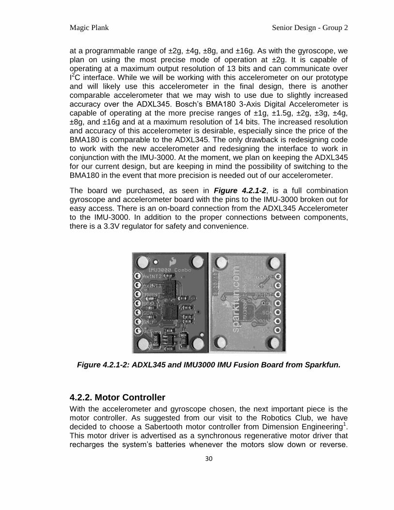
Magic Plank Senior Design - Group 2
30
at a programmable range of ±2g, ±4g, ±8g, and ±16g. As with the gyroscope, we plan on using the most precise mode of operation at ±2g. It is capable of operating at a maximum output resolution of 13 bits and can communicate over I2C interface. While we will be working with this accelerometer on our prototype and will likely use this accelerometer in the final design, there is another comparable accelerometer that we may wish to use due to slightly increased accuracy over the ADXL345. Bosch’s BMA180 3-Axis Digital Accelerometer is capable of operating at the more precise ranges of ±1g, ±1.5g, ±2g, ±3g, ±4g, ±8g, and ±16g and at a maximum resolution of 14 bits. The increased resolution and accuracy of this accelerometer is desirable, especially since the price of the BMA180 is comparable to the ADXL345. The only drawback is redesigning code to work with the new accelerometer and redesigning the interface to work in conjunction with the IMU-3000. At the moment, we plan on keeping the ADXL345 for our current design, but are keeping in mind the possibility of switching to the BMA180 in the event that more precision is needed out of our accelerometer.
The board we purchased, as seen in Figure 4.2.1-2, is a full combination gyroscope and accelerometer board with the pins to the IMU-3000 broken out for easy access. There is an on-board connection from the ADXL345 Accelerometer to the IMU-3000. In addition to the proper connections between components, there is a 3.3V regulator for safety and convenience.
Figure 4.2.1-2: ADXL345 and IMU3000 IMU Fusion Board from Sparkfun.
4.2.2. Motor Controller
With the accelerometer and gyroscope chosen, the next important piece is the motor controller. As suggested from our visit to the Robotics Club, we have decided to choose a Sabertooth motor controller from Dimension Engineering1. This motor driver is advertised as a synchronous regenerative motor driver that recharges the system’s batteries whenever the motors slow down or reverse.

Magic Plank Senior Design - Group 2
31
The Sabertooth 2x12 Dual 12A Motor Driver is capable of driving two brushed motors with up to 12A of continuous current and 25A in bursts. It is capable of providing up to 18V to each motor and comes with a built in 1A switching 5V Battery-Elimination Circuit (BEC) which is capable of powering the microcontroller. It has a lithium cutoff mode that allows it to operate with lithium power supplies, but this mode is optional, which allows for this controller to be powered using a wide range of different power supply solutions. The Sabertooth features its own microcontroller, the ATmega88PA, for handling commands from the main control device. There are four modes of operation for this controller: Mode 1- analog input via PWM; Mode 2 – R/C input using two standard R/C channels to set the speed and direction of the motor; Mode 3 – simplified serial using RS-232 serial data to set the speed and direction; Mode 4 – packetized serial using RS-232 serial data packetized into an address byte, a command byte, a data byte, and 7 bit checksum. During the development of the prototype, we explored the usage of PWM control, simplified serial control, and packetized serial control with both the Texas Instruments Stellaris LM3S8962 and Arduino Uno R3 prototyping boards.
4.2.3. Microcontroller
The first microcontroller chosen for this project was initially the Texas Instruments Stellaris 8962. This ARM Cortex M-3 RISC microcontroller is capable of operating at up to 100 Million Instructions Per Second (MIPS). The primary reason for choosing this microcontroller was due to the TI workshop held at UCF where each person who attended was given a Stellaris LM3S8962 evaluation board free of charge. This 100 pin microcontroller is a very powerful solution with an I2C interface, three Pulse Width Modulation generatorsm two UART interfaces, and a seemingly endless amount of fully programmable digital input pins. Even though this is a very powerful choice, using the development environments needed to program the microcontroller was a confusing process that seemed to be going nowhere. Hours of work configuring TI’s development environment Code Composer Studio followed by hours of work trying to understand the chip led us to the reconsider our microcontroller choice and choice of development environment.
During our reevaluation, we looked toward Arduino, the Italian based open source prototyping platform. Arduino uses Atmel microcontrollers in conjunction with a free and open source Integrated Development Environment (IDE)5. Arduino’s prototyping platforms are designed specifically for easy and rapid prototyping right out of the box with plenty of documentation and community support for all Arduino products. There are two main microcontrollers that Arduino supports: the ATmega328 and ATmega2560. The ATmega2560 is the most comparable microcontroller to the TI Stellaris 8962. They are both 100 pin microcontrollers with plenty of options for I2C, UART, and PWM interfaces, but the ATmega2560 underperforms the Stellaris by a wide margin, operating at 1 MIPS per MHz up to a frequency of 16 MHz giving a maximum instruction

Magic Plank Senior Design - Group 2
32
throughput of 16 MIPS6. This may be only a fraction of the performance of the Stellaris 8962, but it is still sufficient for the main task of reading accelerometer and gyroscope data, processing it, and outputting it to the motor controller. In fact, we can even look at the lower performing ATmega328, which is a 32 pin microcontroller with just a single I2C port and a single UART port. Our design really only requires interfacing through one I2C port to communicate with the Inertial Measuremenr Unit (IMU) and a UART port for serial communication with our steering mechanism. The ATmega328 is capable of operating at a maximum frequency of 20 MHz at the same 1 MIPS per MHz rate, giving it a maximum throughput of 20 MIPS7. The Arduino Uno operates the ATmega328 at a frequency of 16 MHz8, giving us 16 MIPS, so for prototyping purposes, the microcontroller would be operating at this frequency. While analyzing our needs, we decided that the larger ATmega2560 was too much processing power for our purposes, making the ATmega328 our Atmel microcontroller of choice. With our new evaluation of our bare minimum needs for this project, it is clear that the previous choice of the TI Stellaris 8962 is much more than what we need, and in the end, is simply wasteful both from a power consumption perspective and from a development time perspective. The ATmega328 in conjunction with Arduino’s IDE and development libraries make the development process much simpler, which will allow us to more aptly achieve our goals. Based on these factors, we have acquired the Arduino Uno R3 for further development of our balancing platform prototype.
4.3. Hardware Implementation
4.3.1. Remote Control
Because the prototype balance board was constructed primarily for the purpose of proof of concept, it was scaled down to a size which would render the steering and acceleration controls of the full scale model impractical to implement. To control the general movement of the prototype, it was decided to operate the vehicle via remote control. By implementing remote control, it allowed the ability to easily test the prototype's self-correction algorithm through varying speeds and turning rates without needing any direct contact with the device and whilst avoiding any potential complications that could arise from having to follow it around with a wired controller. Controlling the prototype via remote control also provides the project with another challenge, however, as it was another area of unfamiliar ground which needed to be researched. The first task was to narrow down the different types of remote control solutions that could be implemented into the prototype that were compatible with the design that had been envisioned. A primary difficulty that was encountered was the fact that a fair amount of the remote control implementations that were encountered were very inflexible, as they were designed with a specific type of product in mind. Because of this, these devices are built in such a way that they would only interface directly with a motor controller. While this would normally be

Magic Plank Senior Design - Group 2
33
ideal since, conceptually, one would want the remote controller to be able to directly influence the throttle and steering of the prototype balancing board, this is not a viable solution to this particular design since the board has several other factors it needs to consider which dictate the speed of the prototype other than just the input from the controller. To this end, it was needed to narrow the search down to remote control receivers which could interface directly with the Arduino development board so that the information the receiver would have received from the controller could be read in, interpreted and translated into the correct directions, combined with the information received from the gyroscope and accelerometer on the Inertial Measurement Unit, and analyzed so that the micro-controller can make an informed decision as to the correct course of action to take. Our initial idea in the process of implementing a remote control system on the prototype was to use a radio control device. Radio control seemed to be the obvious option, as the technology is relatively simple and is something that everyone in the group is familiar with. To this extent, the Futaba 3PRKA 2.4GHz S-FHSS 3-Channel Radio System was acquired. This appeared to be a viable solution to the task, as the system included all the necessary components required for the operation of a generic R/C car (which, since all that was required of the system was the ability to accelerate, decelerate, and turn, seemed to be a perfect fit). The system included a 2.4GHz 3-channel receiver which could interface directly with the Arduino development board, an intuitive transmitter which allowed for the fine tuning of both the steering and the throttle, and a fail-safe which disables the device should it move out of range of the transmitter. The only flaw with using the Futaba 3PRKA 2.4GHz S-FHSS 3-Channel Radio System is the fact that, because it is an entire kit designed specifically for use with standard hobby shop R/C cars, it is difficult to interface with it as there is little to no information available on the protocols it uses to communicate with. Without this information it would have been difficult, if not impossible, to use it to fit the needs of the prototype. Because most of the radio control alternatives that were researched would either stretch the finances too thin or be unusable due to the lack of information on their communication protocols, a Bluetooth-based solution was instead implemented to the remote control initiative. Utilizing the Bluetooth SMD Module – RN – 42 enables the ability to control the balance board through any Bluetooth-enabled device with the proper software that supports SPP, from a cell phone to a laptop. The SMD Module – RN – 42 is an ideal wireless communication device for the prototype, as it provides an acceptable transmission range of 60 feet for the prototype1. Another perk of the device is its low power consumption, consuming only 26 uA while in sleep mode and a maximum of 30 mA while transmitting1. The low power consumption makes this solution perfect for the battery-powered design. The SMD Module – RN – 42 also supports multiple interface protocols (including UART), making it flexible enough to give options as to how to have it

Magic Plank Senior Design - Group 2
34
communicate with the Arduino development board. The SMD Module – RN – 42 also comes with built-in error correction for its data transfers, guaranteeing packet delivery1. Finally, the SMD Module – RN – 42 comes equipped with auto-discovery and auto-pairing with other Bluetooth devices, making its process of connecting with the chosen controller require no additional software configurations1. A summary of the comparison between the Bluetooth implementation and the radio control implementation is shown in Table 4.3.1-1 below.
Average Observed
Price Range
Communication Protocol
Availability
Bluetooth $15 - $40 for receiver
$30 - $50 for transmitter
Unknown / Unique to each
device
Widely Available
Radio Control $15 - $50 for receiver
UART Serial, USB
Widely Available
Advantage: Bluetooth Bluetooth Tie
Table 4.3.1-1: Description of control implementations and their advantages.
Fitting the SMD Module – RN – 42 into the design is a simple enough task, given the versatility of the Arduino development board. The SMD Module – RN – 42 can interface directly with the Arduino development board, allowing it to provide the feedback it receives from the remote controller directly to the board. The Arduino development board is then able to interpret the information via the UART interface protocol and output these commands to the motor controller, effectively allowing the SMD Module – RN – 42 to control the behavior of the motor controller as intended while not requiring direct control of the motor controller. In order to interface with the Arduino development board, it was required to research the correct pins that would be required to both communicate input and receive output from the board, which pins were required to provide power and ground sources, and which pins would need to be shorted in order to avoid confusion while the Arduino development board is trying to communicate with the SMD Module – RN – 42. Because the ability of the SMD Module – RN – 42 to communicate via the UART protocol available on the Arduino development board is going to be utilized, the first objective was to establish that communication channel. As it turned out, the research showed that the connections were much more intuitive than had been initially thought. Ports 13 and 14 on the SMD Module – RN – 42 (UART_RX and UARD_TX, respectively) connect directly to the ports TX and RX on the Arduino development board, with UART_RX pairing
Magic Plank Senior Design - Group 2
35
with the TX and UART_TX pairing with RX. Pins 15 and 16, UART_RTS and UART_CTS, are to be tied together to enable hardware flow control5. All that is left for communicating with the Arduino board is to connect one of the ground pins 1, 12, 28, or 29 all to a common ground and a 3.3V power source to pin 11. An issue that was stumbled upon while designing the Bluetooth implementation was that while the Arduino development board was capable of sending the 3.3V signal required to power the SMD Module – RN – 42, the SMD Module – RN – 42’s pins are intolerant to the 5V supplied by the Arduino board, requiring a 3.3V signal to operate. Without the proper voltage, the UART_TX and UART_RX pins would be unusable. To counteract this, it was needed to implement some method which would be able to step the 5V output of the Arduino development board down to a usable 3.3V. A few methods to accomplish this were. One of the solutions that was considered for this issue was simply to purchase a Logic Level Converter. A Logic Level Converter, available from SparkFun.com, is a small device that can be used to step down a 5V signal to a 3.3V signal, or it can be used to step a 3.3V signal up to a 5V signal. Using the device is rather simple, as it requires only that the UART_TX, UART_RX, UART_CTS, UART_RTS, GND and VDD pins of the SMD Module – RN – 42 be connected to the correct corresponding locations on the Logic Level Converter for it to correctly step up or step down the voltage. The other alternative was to simply purchase two additional MOSFET transistors (2N7000) and four more 10k ohm resistors in order to utilize the same solution that had been deployed for a similar issue with the Inertial Measurement Unit. As shown in Figure 4.3.2-1 the four 10k ohm resistors and the two MOSFET transistors can be arranged in such a way as to step down the 5V signal being provided by the Arduino development board to a 3.3V signal, allowing it to be used by the SMD Module – RN – 42. While this method would require the constant use of a breadboard, its simplistic design, cheap components, and availability made it an ideal solution to the voltage requirements. Because of these factors, it was decided to use the voltage converter. There were several different options considered when the decision of what medium should be chosen to actually transmit the commands to the SMD Module – RN – 42 was brought up. A clear and obvious prerequisite is that whatever device would be used must be Bluetooth compatible. Beyond the Bluetooth compatibility, the controller would also need to be able to be operated intuitively, as it would be cumbersome to have to learn to drive the balancing platform if it is more complex than something as simple as “up means go forward”. With this in mind, the decision was narrowed to the following possible devices which could control the Bluetooth-enabled balancing platform: an Android-powered cellular phone, a Sony PlayStation 3 wireless controller, a laptop computer with Bluetooth capabilities, and a Nintendo Wii wireless remote controller.
Magic Plank Senior Design - Group 2
36
Using an Android-powered cellular phone to control the balance board seemed a rather intuitive solution to the problem, as an Android cellular phone (just like many other cellular phones) has software built in to its core programming with allows it to pair up with other Bluetooth-enabled devices within its area of discovery. With the SMD Module – RN – 42 installed, all that's required of the Android cellular phone is to have the proper software installed which would allow it to communicate the commands to the Bluetooth module. There is a featured File/Application Manager which can a explore a phone's Bluetooth files called ES File Explorer that, when installed onto an Android cellular phone, allows a user more control over the interactions between the cellular phone and whatever device it has been paired with other than the simple transmission of files2. The Android-powered cellular phone then can utilize a software toolkit known as Amarino. The Amarino toolkit was designed specifically to streamline the interactions between Android-powered cellular phones and Arduino development boards and processors3. With the Amarino application and plugins installed onto the Android-powered cellular phone, the setup for the Android is completed. With the Android-powered cellular phone set up with the proper software to allow it to communicate with the SMD Module – RN – 42, the only thing that would be left to be configured would be the Arduino development board. To accomplish this, all that is required is to simply download the Arduino Library to any available computer. Once the Arduino Library has been downloaded, it can then be extracted to a libraries folder. With the libraries successfully extracted, all that's left is to connect the Arduino development board to the computer via USB to the computer with all of the files and to upload them, along with the behavioral code, to the board2. The Android-powered cellular phone would then control the balancing platform through the orientation of the phone, where tilting the phone to either the left or the right would command the balancing platform to turn to the respective direction, while tilting it either forward or backward would command the platform to either accelerate forward or to drive in reverse. With the ready availability of the files required to properly set up an Android-powered cellular phone to act as the remote control device for the balancing platform, the idea of using an Android-powered cellular phone quickly became a strong contender for the device of choice; however, the research continued regardless. The next device that was considered was a Sony PlayStation 3 wireless controller. This device, while not providing the simplicity of implementation of simply downloading and transferring some files and libraries as the Android-powered cellular phone controller would, offers a far more familiar control scheme than the previously researched implementation method. While the Android-powered cellular phone would require either the twisting of the phone to communicate when to turn or accelerate in which direction or the pressing of an arrow button on a programmed GUI interface which would steer the balance board in the direction of the arrow, utilizing a PlayStation 3 wireless controller would provide familiar controls with the directional pad. The PlayStation 3

Magic Plank Senior Design - Group 2
37
wireless controller was already designed to fit comfortably in the user's hands, with the directional pad located comfortably in reach of the thumb. The directional pad is very simplistic, in that the left arrow would indicate a left turn, the up arrow would indicate a desire to accelerate forward, the right arrow would indicate a right turn, and the down arrow would indicate a desire to drive in reverse. Setting up the Sony PlayStation 3 wireless controller to be able to send commands to the SMD Module – RN – 42 involves a bit more configuring than using an Android-powered cellular phone, but still involves doing the majority of the configuration from an available desktop or laptop computer. The device and configuration descriptors can be acquired through plugging the Sony PlayStation 3 wireless controller into a USB port on the computer and running a program such as USBView4. This is important, as while it is possible that this information could have been previously documented and provided, it is rather unlikely. One could then install the USB Host Shield and download the USB_Desc sketch in order to read the device and configuration descriptors using the Arduino development board4. With the information derived from the previous USB descriptors the USB library can be modified to be configured specifically to the Sony PlayStation 3 wireless controller’s specifications. With the communication established, the Arduino development board can then be set up to receive commands in the format that the PlayStation 3 wireless controller sends them. There are plenty of software solutions available through which one could “sniff” the connection that is held between the PlayStation 3 wireless controller in order to distinguish the commands that are to be sent between the controller and the Bluetooth module. The previously mentioned software will also produce reports of the values generated by the PlayStation 3 wireless controller. The accelerometer and gyroscope values that are detected can be used from their report as soon as some minor formatting is performed on their type structures. The PlayStation 3 wireless controller’s USB library contains support for interfacing the controller and the Arduino development board. The USB library contains the majority of the information that would be used to determine the user’s commands when controlling the balancing platform, including recognizing the pressing of the game controller’s buttons, movements of the joystick in any direction, as well as being able to detect the game controller’s physical movements through its built-in accelerometers. Of equal importance is the USB library’s providing of the Bluetooth addresses for reading and writing for use in pairing when the devices are in Bluetooth mode. With the information provided, all that would be required would be configuring the data provided from the reports to integrate the PlayStation 3 wireless controller’s Bluetooth data with the SMD Module – RN – 42 attached to the Arduino development board to allow communication between the two once they’ve been paired. With the steps laid out in advance, further means of communication to the SMD Module – RN – 42 could be explored to make sure the decision was the best available.

Magic Plank Senior Design - Group 2
38
The next potential controller that was explored was simply controlling the balancing platform from a nearby laptop with Bluetooth capabilities. Implementing this method is the easiest of the three discussed so far as, unlike with the Android-powered cellular phone, the software available and the sheer processing power of a laptop is far more vast; also, the adjustments and configurations done to the acquired software and libraries which would allow it to communicate correctly with the SMD Module – RN – 42 would be done directly to the laptop, unlike like the PlayStation 3 wireless controller which used a laptop or desktop computer to detect its Bluetooth settings and make changes to its configurations. Much like an Android-powered cellular phone, a laptop is also capable of detecting any other nearby Bluetooth-enabled devices when in a discovery mode. To this end, a laptop would only need to have the proper software and firmware downloaded and installed which would allow it to communicate to the SMD Module – RN – 42. This software is just as, if not more, available to download as the Android-powered cellular phone equivalent solution. An example of such software is Bluetooth Remote Control which, as its name suggests, is designed in such a way to make the configuring of a Bluetooth controlled device via laptop almost simple enough that a novice could make progress with a similar project. The process of configuring the Arduino development board to be able to communicate with a Bluetooth-enabled laptop is also a relatively simple process as it is nearly identical to the process used to interface it with an Android-powered cellular phone. With the Arduino Library downloaded to the laptop being used, all that is required is to connect the laptop to the Arduino development board via a USB connection to upload it, along with the behavioral code, to the development board in order to fine tune the interfacing between the two devices. The behavioral code would be able to determine just how the laptop will issue the commands to be received by the SMD Module – RN – 42 onboard the Arduino development board, be it through a WASD command system, through the arrow directional keys, through a GUI developed specifically for the project, or through any other developed means. The final method that was researched was the ability to control the balance board through the Nintendo Wii wireless remote controller. Because of the nature of the Nintendo Wii wireless remote controller, the process of configuring the controller is very similar to that of the PlayStation 3 wireless controller. The primary difference between the two is in how the controllers actually connect to the SMD Module – RN – 42. The PlayStation 3 wireless controller initiates the connection with the Arduino development board, as the controller does not respond to requests for inquiry or connection4. Because of this, the PlayStation 3 wireless controller must first know the Bluetooth address of the Arduino development board in order to establish a connection to it. The Nintendo Wii wireless remote controller, however, operates in an opposite fashion: the method that would be utilized, known as soft connect, requires that the Arduino development board
Magic Plank Senior Design - Group 2
39
makes the connection to the controller using a previously discovered Bluetooth address of the Nintendo Wii wireless remote controller. There is a sketch available known as BlueUtils which can be run to discover the device’s Bluetooth address which, when notified that the process is searching for devices, allows the user to simultaneously press the “1” and “2” buttons on the controller to receive an output of information about the controller which includes its Bluetooth address. The pros and cons of the four researched methods would be the ultimate deciding factor for which device would be the one to operate the balance board prototype. While utilizing an Android-powered cellular phone would make pairing the device with the SMD Module – RN – 42 a simple task, the SMD Module – RN – 42 comes standard with an auto-pairing feature which renders that convenience obsolete. Establishing a control system via an Android app which would interact with the Arduino development board would be an unnecessary burden, and the system of relying on the tilt of the Android phone to steer and control the throttle of the balance platform is clunky as the detection of angle changes in the phone isn’t as smooth as would be required to comfortably control the balance platform; because of these two factors, it was decided against implementing the Android-powered cellular phone alternative. The laptop-based solution comes with a high degree of flexibility in terms of fine-tuning how we’d like to control the balance board. Maintaining the system also becomes rather easy as the device through which the balance board is being controlled also happens to be the means through which the code can be adjusted, making transitioning between testing and troubleshooting rather simple. The main perceived drawback of using a laptop controller is the lack of mobility. The previously considered options were all small, lightweight devices designed for hand-held use, while a laptop is a relatively heavy piece of hardware designed to be used while atop a flat, stationary surface. While this isn’t a huge drawback, it does limit the environments and situations through which the balance platform could be tested. Because of this limitation, it was decided to forgo the laptop design and instead continue looking at the wireless video game controller options. The decision between the Sony PlayStation 3 wireless controller and the Nintendo Wii wireless controller, due to their similar implementations and configurations, came down to a very simple factor: there was access to Wii remote controllers, but there was no ready access available to a PlayStation 3 controller. Because the implementation of either device would be nearly identical, this was not a large disadvantage; therefore, it was decided that the Nintendo Wii wireless controller would be used as the controller of choice to transmit the steering and throttle choices of the user to the SMD Module – RN – 42. The final comparisons between the possible remote control implementations are summarized in Table 4.3.1-2 below.
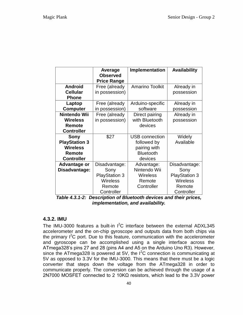
Magic Plank Senior Design - Group 2
40
Average Observed
Price Range
Implementation Availability
Android Cellular Phone
Free (already in possession)
Amarino Toolkit Already in possession
Laptop Computer
Free (already in possession)
Arduino-specific software
Already in possession
Nintendo Wii Wireless Remote
Controller
Free (already in possession)
Direct pairing with Bluetooth
devices
Already in possession
Sony PlayStation 3
Wireless Remote
Controller
$27 USB connection followed by pairing with Bluetooth devices
Widely Available
Advantage or Disadvantage:
Disadvantage: Sony
PlayStation 3 Wireless Remote
Controller
Advantage: Nintendo Wii
Wireless Remote
Controller
Disadvantage: Sony
PlayStation 3 Wireless Remote
Controller
Table 4.3.1-2: Description of Bluetooth devices and their prices, implementation, and availability.
4.3.2. IMU
The IMU-3000 features a built-in I2C interface between the external ADXL345 accelerometer and the on-chip gyroscope and outputs data from both chips via the primary I2C port. Due to this feature, communication with the accelerometer and gyroscope can be accomplished using a single interface across the ATmega328’s pins 27 and 28 (pins A4 and A5 on the Arduino Uno R3). However, since the ATmega328 is powered at 5V, the I2C connection is communicating at 5V as opposed to 3.3V for the IMU-3000. This means that there must be a logic converter that steps down the voltage from the ATmega328 in order to communicate properly. The conversion can be achieved through the usage of a 2N7000 MOSFET connected to 2 10KΩ resistors, which lead to the 3.3V power
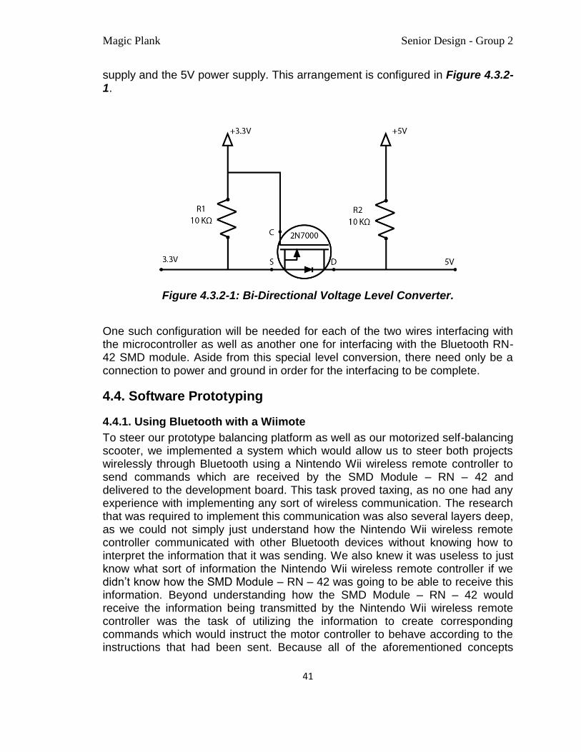
Magic Plank Senior Design - Group 2
41
supply and the 5V power supply. This arrangement is configured in Figure 4.3.2-1.
Figure 4.3.2-1: Bi-Directional Voltage Level Converter.
One such configuration will be needed for each of the two wires interfacing with the microcontroller as well as another one for interfacing with the Bluetooth RN-42 SMD module. Aside from this special level conversion, there need only be a connection to power and ground in order for the interfacing to be complete.
4.4. Software Prototyping
4.4.1. Using Bluetooth with a Wiimote
To steer our prototype balancing platform as well as our motorized self-balancing scooter, we implemented a system which would allow us to steer both projects wirelessly through Bluetooth using a Nintendo Wii wireless remote controller to send commands which are received by the SMD Module – RN – 42 and delivered to the development board. This task proved taxing, as no one had any experience with implementing any sort of wireless communication. The research that was required to implement this communication was also several layers deep, as we could not simply just understand how the Nintendo Wii wireless remote controller communicated with other Bluetooth devices without knowing how to interpret the information that it was sending. We also knew it was useless to just know what sort of information the Nintendo Wii wireless remote controller if we didn’t know how the SMD Module – RN – 42 was going to be able to receive this information. Beyond understanding how the SMD Module – RN – 42 would receive the information being transmitted by the Nintendo Wii wireless remote controller was the task of utilizing the information to create corresponding commands which would instruct the motor controller to behave according to the instructions that had been sent. Because all of the aforementioned concepts

Magic Plank Senior Design - Group 2
42
were foreign to the team, this particular challenge proved to be very research intensive.
Writing a sketch for the Arduino development board required first researching the basic skeleton of what the sketch requires. We learned that there are two primary functions which must exist in any Arduino development board sketch, regardless of the functionality of the sketch: setup() and loop(). The setup() function is the first function which is called when a sketch is started either by initially being powered on or by having the Arduino development board’s reset button pressed1. The function’s name is very indicative of what its purpose is, since it is used to initialize variable, pin modes, start using libraries, and any other processes or functions which must be initiated prior to the loop() function being run. This function, while essential to the execution of the sketch’s code, is only run once per power-up or reset toggle1.
After the setup() function has been created with all of the necessary beginnings of the sketch, the loop() function is required. We discovered that the loop() function is very similar to the main() function in many coding languages in that it houses the code which will essentially be performing what the sketch is meant to perform. The loop() function, unlike the more common main() function, does exactly what its name suggests: it loops endlessly and consecutively, allowing the program to actively change and respond1. It is the loop function that will be controlling the Arduino board and allowing it to respond and adapt according to our coding specifications in Table 4.4.1-1.

Magic Plank Senior Design - Group 2
43
Button Number (dec)
Value (hex)
Two 1 0x0001
One 2 0x0002
B 3 0x0004
A 4 0x0008
Minus 5 0x0010
? motion ? 6 0x0020
? motion ? 7 0x0040
Home 8 0x0080
Left 9 0x0100
Right 10 0x0200
Down 11 0x0400
Up 12 0x0800
Plus 13 0x1000
? motion ? 14 0x2000
? motion ? 15 0x4000
? Reading Mii ? 16 0x8000
Table 4.4.1-1: Nintendo Wii Wireless Controller Bit Assignments.
With a basic understanding of the structure required for an Arduino development board script, the next endeavor was to understand how to allow the Nintendo Wii wireless remote controller to communicate with our Arduino development board through the SMD Module – RN – 42. Understanding how to develop the communication between the Nintendo Wii wireless remote controller and the SMD Module – RN – 42 required an understanding of the basic functionality of the Wii controller itself. Our research revealed that the Nintendo Wii wireless remote controller possesses twelve buttons total (including four buttons for each of the buttons on the directional pad). Straight out of the package, the Nintendo Wii wireless remote controller is set up so that whenever a button is pressed or released a packet will be sent to the paired receiver, through the Bluetooth Human Interface Device standard, with “a payload containing a 2-byte bitmask with the current state of all the buttons.”2 An example of this would be when a button on the Nintendo Wii Wireless remote controller is pressed, a Bluetooth Human Interface Device data input packet is transmitted from the controller of
Magic Plank Senior Design - Group 2
44
“(a1) 30 00 08”. “(a1)” indicates that the packet sent was a data input packet (0xa1), “30” indicates the data was sent on channel 0x30, and the data sent was a two byte payload of 0x00 and 0x08. According to Table 4.4.1-1, which displays bit assignments in big endian order, 0x0008 corresponds to the pressing of the ‘A’ button which indicates that the ‘A’ button is currently being held down. When the button is released, another packet of “(a1) 30 00 00” is sent, indicating that the ‘A’ button is no longer being held down. Contrary to what we had initially assumed, what data the Nintendo Wii wireless remote controller sent out had to be set manually, as there simply are not enough available bytes for the controller to send out all of the possible data types with any given data packet transmission. The reason for the unavailability of bytes to transmit all available information is due to the fact that each of the controller’s peripherals generate and determine the data formats themselves, leaving the controller to simply have to transmit the data. To handle this, the Nintendo Wii wireless remote controller has several different data reporting modes.3 Each mode is able to send a unique combination of the controller’s core data features to the host through one of the report IDs which are determined by the specific mode the controller is configured in. We will be able to toggle between the data reporting modes by sending a two-bye command to the specific report 0x12 in the format of “(a2) 12 TT MM”. The TT bits default to only forcing the Nintendo Wii wireless remote controller to send an output report when there has been a change in data. We will be able to change the reporting mode by changing the bits represented by MM. The mode that we will be using is 0x31, which will output a report containing data for the core buttons and the accelerometer included in the Nintendo Wii wireless remote controller, as our project has no need for any of the controller’s infrared sensors or its expansion port. Learning how to set up the SMD Module – RN – 42 to be able to receive the information from the Nintendo Wii wireless remote controller proved to be a simpler task than translating the information from the controller. Out of the box, the SMD Module – RN – 42 is set up to be able to receive information from any Bluetooth-enabled device due to it being set up in slave mode by default. The pairing process of the SMD Module – RN – 42 is quite simple as well, as it only requires our Nintendo Wii wireless remote controller to begin searching for a device to pair with (this is accomplished by the pressing and holding of the controller’s “1” and “2” buttons) and the subsequent entering of the default pin code of “1234”. With the two devices paired, the general setup of the SMD Module – RN – 42 is complete enough for our purposes. Understanding how the commands transmitted from the Nintendo Wii wireless remote controller would be utilized to influence the steering of our prototype balancing platform involved at least a basic understanding of basic coding practices. Our research revealed that there were several different libraries available online that previous developers had created in the past which could be used to set up a foundation for storing the various data that would be transmitted
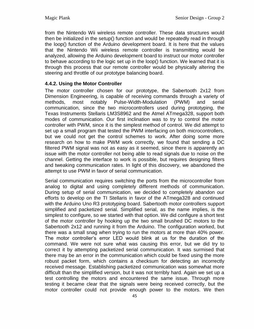
Magic Plank Senior Design - Group 2
45
from the Nintendo Wii wireless remote controller. These data structures would then be initialized in the setup() function and would be repeatedly read in through the loop() function of the Arduino development board. It is here that the values that the Nintendo Wii wireless remote controller is transmitting would be analyzed, allowing the Arduino development board to instruct our motor controller to behave according to the logic set up in the loop() function. We learned that it is through this process that our remote controller would be physically altering the steering and throttle of our prototype balancing board.
4.4.2. Using the Motor Controller
The motor controller chosen for our prototype, the Sabertooth 2x12 from Dimension Engineering, is capable of receiving commands through a variety of methods, most notably Pulse-Width-Modulation (PWM) and serial communication, since the two microcontrollers used during prototyping, the Texas Instruments Stellaris LM3S8962 and the Atmel ATmega328, support both modes of communication. Our first inclination was to try to control the motor controller with PWM, since it is the simplest method of control. We did attempt to set up a small program that tested the PWM interfacing on both microcontrollers, but we could not get the control schemes to work. After doing some more research on how to make PWM work correctly, we found that sending a DC filtered PWM signal was not as easy as it seemed, since there is apparently an issue with the motor controller not being able to read signals due to noise on the channel. Getting the interface to work is possible, but requires designing filters and tweaking communication rates. In light of this discovery, we abandoned the attempt to use PWM in favor of serial communication.
Serial communication requires switching the ports from the microcontroller from analog to digital and using completely different methods of communication. During setup of serial communication, we decided to completely abandon our efforts to develop on the TI Stellaris in favor of the ATmega328 and continued with the Arduino Uno R3 prototyping board. Sabertooth motor controllers support simplified and packetized serial. Simplified serial, as the name implies, is the simplest to configure, so we started with that option. We did configure a short test of the motor controller by hooking up the two small brushed DC motors to the Sabertooth 2x12 and running it from the Arduino. The configuration worked, but there was a small snag when trying to run the motors at more than 40% power. The motor controller’s error LED would blink at us for the duration of the command. We were not sure what was causing this error, but we did try to correct it by attempting packetized serial communication. It was surmised that there may be an error in the communication which could be fixed using the more robust packet form, which contains a checksum for detecting an incorrectly received message. Establishing packetized communication was somewhat more difficult than the simplified version, but it was not terribly hard. Again we set up a test controlling the motors and encountered the same issue. Through more testing it became clear that the signals were being received correctly, but the motor controller could not provide enough power to the motors. We then

Magic Plank Senior Design - Group 2
46
proceeded to disconnect one of the motors, giving us a larger power range of up to 60%. It was clear that a 9V supply was not sufficient to power our motors. The reasons for failure were twofold: first, the motors were rated for 12V each and supplied by a 9V battery, so the voltage supply was not sufficient to power both motors. Second, the motors were rated at a current draw of 3A1, which the battery could not support. It was capable of supplying high current in short bursts, but had difficulty doing so consistently. Our initially alarming issue turned out to be no issue at all, as a larger power supply could easily provide the power needed to drive these motors. The 9V alkaline battery had served its purposes for initial testing.
Continuing with testing, we found that during usage of packetized serial mode, there was a small lag time in between the two motors responding. This could have been due to the transmission and processing time between the two separate packets for each motor. Although it was not a functionally critical issue, it was slightly annoying that one motor lagged behind the other at a noticeable rate. Two solutions to this problem were to switch to simplified serial or operate in differential drive mode. This seemed to be a road block, since we were not sure how the platform would handle balancing in differential drive mode, so coming to a conclusion on the better method would have to wait until we could test the input from the accelerometer and gyroscope. Initial tests in differential drive mode did seem promising, though. Using differential drive commands means less data sent and both motors update synchronously. Without the input from external sensor data, however, it was impossible to know which control method was truly superior.
4.5. Prototype Implementation
We approached our prototype implementation with the mindset of mimicking the way we are going to set up all our electrical and physical hardware. Basically we all had ideas on how all the electrical and physical hardware should be arranged on the platform, so after so discussion and reworking of the concept sketches of layout and arrangement, we were able to come up with a design that we could not only use on our prototype implementation, but also use on our final implementation. The logic behind this decision is we wanted to be able to troubleshoot and problem solve much of the potential issues we would face during the final implementation build process. That way we would be prepared to handle the build process with as little stress as possible. In addition, this would allow us more time to work on refining and calibrating our system critical functions. Since we are using small twelve Volt motors that came with no mount housing or bolts we are going to have to attach them directly to our platform. We addressed this problem by mounting the motors with U – bolts with a rubber washer between the motor and platform. The rubber washer limits the vibrations from
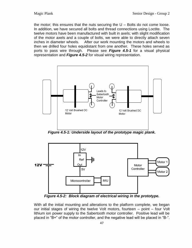
Magic Plank Senior Design - Group 2
47
the motor; this ensures that the nuts securing the U – Bolts do not come loose. In addition, we have secured all bolts and thread connections using Loctite. The twelve motors have been manufactured with built in axels; with slight modification of the motor axels and a couple of bolts, we were able to directly attach seven inches in diameter wheels. After our work mounting the motors and wheels to then we drilled four holes equidistant from one another. These holes served as ports to pass wire through. Please see Figure 4.5-1 for a visual physical representation and Figure 4.5-2 for visual wiring representation.
Figure 4.5-1: Underside layout of the prototype magic plank.
Figure 4.5-2: Block diagram of electrical wiring in the prototype.
With all the initial mounting and alterations to the platform complete, we began our initial stages of wiring the twelve Volt motors, fourteen – point – four Volt lithium ion power supply to the Sabertooth motor controller. Positive lead will be placed in “B+” of the motor controller, and the negative lead will be placed in “B-”.

Magic Plank Senior Design - Group 2
48
Next we placed the first motor’s leads in to slots “M1A” and “M1B”; the same is done for the second motor in the respective slots labeled “M2A” and “M2B”. Pins “S2” and “S1” of the Sabertooth interface and communicate with twelve and 13 with the ATMEGA 328P Arduino Uno development board, as seen in Figure 4.5-3 and Table 4.5-1. The power supply and the motor controller are then mounted to the top side of the platform. Once mounting is completed the power supply will be disconnected from the main platform until all mounting and securing has been completed.
Figure 4.5-3: Block diagram of the connections between the Sabertooth
2x12 and Arduino Uno R3.
Arduino Uno R3 Pin Connection Summary
12 Sabertooth 2x12 s1
13 Sabertooth 2x12 s2
Table 4.5-1: Description of pin connection between the Sabertooth 2x12 and Arduino Uno R3.
After all connections are secured and double checked we move to mounting the ATMEGA 328P Arduino Uno development board, as well as the Bluetooth RN - 42. Once we have completed the mounting and securing process we proceed to set pin connections between both the pieces of electronic hardware. Pins zero and one on the ATMEGA 328P Arduino Uno development board communicate with pins thirteen and fourteen on the Bluetooth RN – 42, as seen in Figure 4.5-3 and Table 4.5-1 This pin communication setup allows us to send signals Wii – mote, a Bluetooth device. Then Bluetooth RN – 42 translate those signals and relays the commands to the ATMEGA 328P Arduino Uno. This pin set is directly translatable to our final implementation; pin zero and one are directly from the ATMEGA 328P.
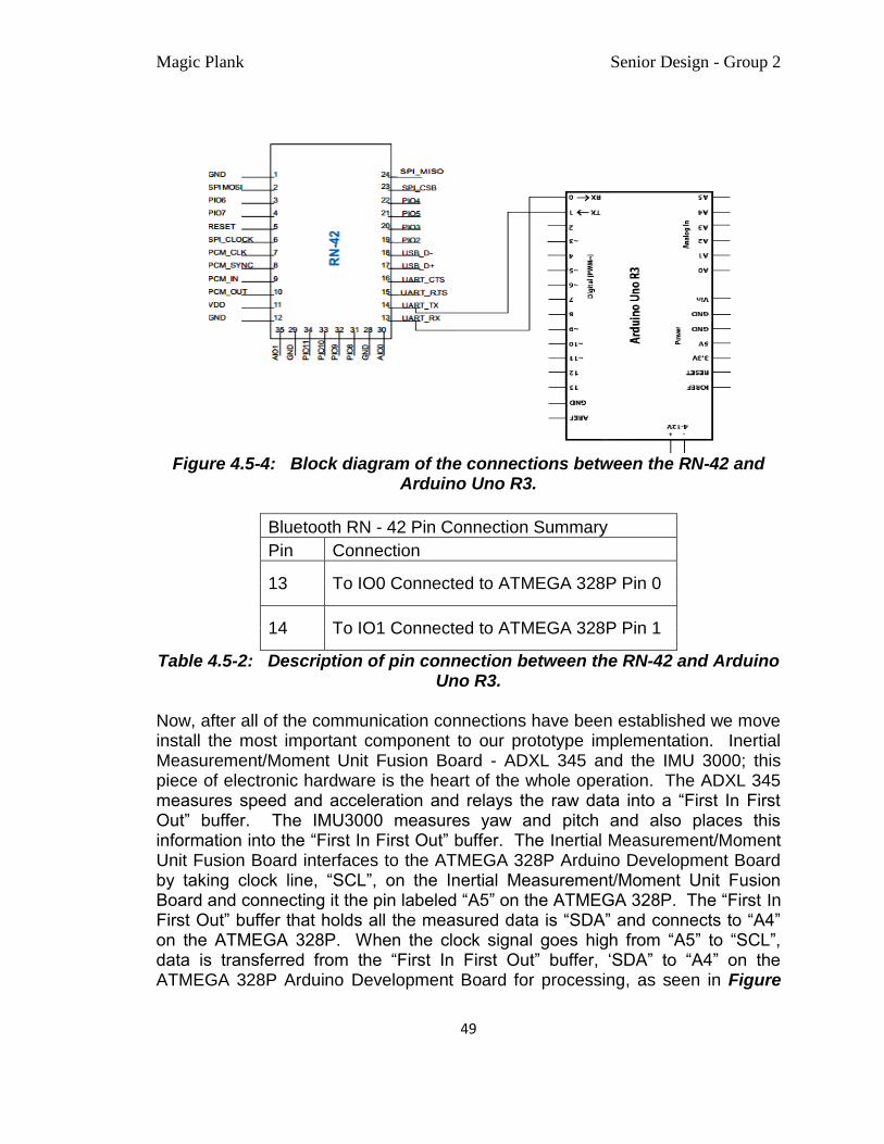
Magic Plank Senior Design - Group 2
49
Figure 4.5-4: Block diagram of the connections between the RN-42 and
Arduino Uno R3.
Bluetooth RN - 42 Pin Connection Summary
Pin Connection
13 To IO0 Connected to ATMEGA 328P Pin 0
14 To IO1 Connected to ATMEGA 328P Pin 1
Table 4.5-2: Description of pin connection between the RN-42 and Arduino Uno R3.
Now, after all of the communication connections have been established we move install the most important component to our prototype implementation. Inertial Measurement/Moment Unit Fusion Board - ADXL 345 and the IMU 3000; this piece of electronic hardware is the heart of the whole operation. The ADXL 345 measures speed and acceleration and relays the raw data into a “First In First Out” buffer. The IMU3000 measures yaw and pitch and also places this information into the “First In First Out” buffer. The Inertial Measurement/Moment Unit Fusion Board interfaces to the ATMEGA 328P Arduino Development Board by taking clock line, “SCL”, on the Inertial Measurement/Moment Unit Fusion Board and connecting it the pin labeled “A5” on the ATMEGA 328P. The “First In First Out” buffer that holds all the measured data is “SDA” and connects to “A4” on the ATMEGA 328P. When the clock signal goes high from “A5” to “SCL”, data is transferred from the “First In First Out” buffer, ‘SDA” to “A4” on the ATMEGA 328P Arduino Development Board for processing, as seen in Figure
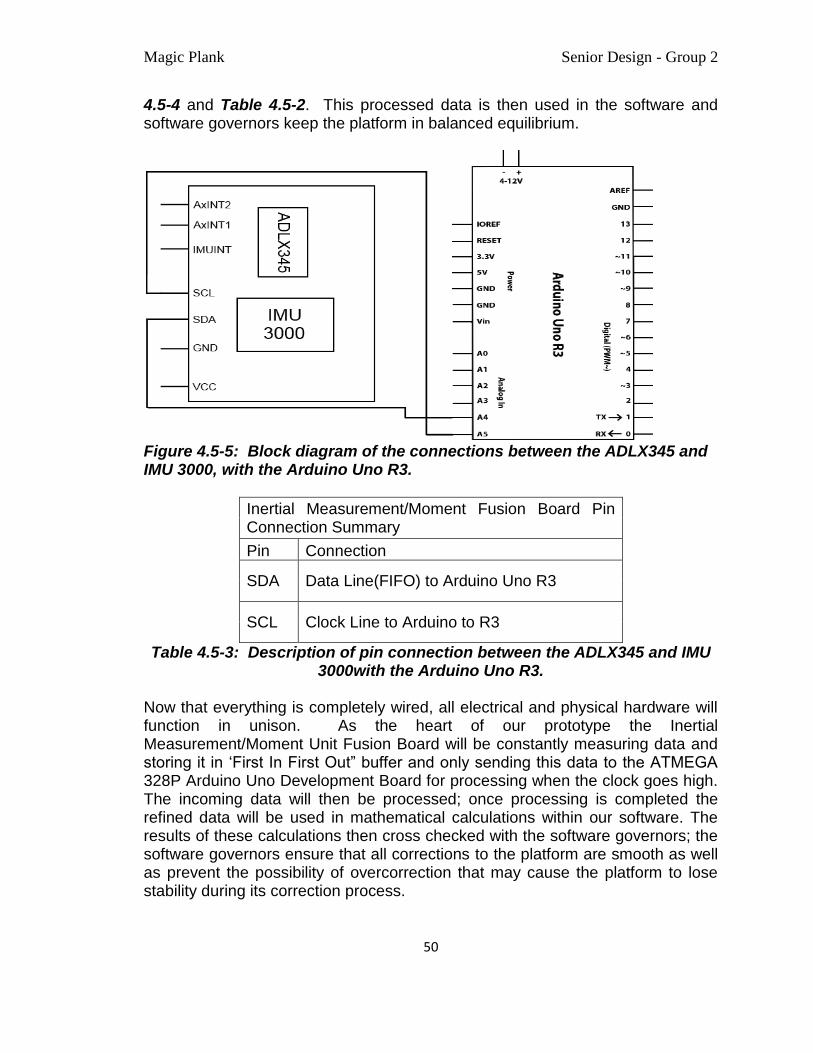
Magic Plank Senior Design - Group 2
50
4.5-4 and Table 4.5-2. This processed data is then used in the software and software governors keep the platform in balanced equilibrium.
Figure 4.5-5: Block diagram of the connections between the ADLX345 and IMU 3000, with the Arduino Uno R3.
Inertial Measurement/Moment Fusion Board Pin Connection Summary
Pin Connection
SDA Data Line(FIFO) to Arduino Uno R3
SCL Clock Line to Arduino to R3
Table 4.5-3: Description of pin connection between the ADLX345 and IMU 3000with the Arduino Uno R3.
Now that everything is completely wired, all electrical and physical hardware will function in unison. As the heart of our prototype the Inertial Measurement/Moment Unit Fusion Board will be constantly measuring data and storing it in ‘First In First Out” buffer and only sending this data to the ATMEGA 328P Arduino Uno Development Board for processing when the clock goes high. The incoming data will then be processed; once processing is completed the refined data will be used in mathematical calculations within our software. The results of these calculations then cross checked with the software governors; the software governors ensure that all corrections to the platform are smooth as well as prevent the possibility of overcorrection that may cause the platform to lose stability during its correction process.

Magic Plank Senior Design - Group 2
51
Now adding in the steering controller, The Inertial Measurement/Moment Unit Fusion Board continues taking data on speed, acceleration, yaw, and pitch. The Bluetooth RN – 42 will receive the steering commands from the Wii - mote and relay them through the ATMEGA 328P Arduino Uno Development board to the Sabertooth motor controller; to turn left or right, accelerate or decelerate, or move forward of go in reverse. During this command process the Inertial Measurement/Moment Unit Fusion Board will send the buffered data trough the ATMEGA 328P. Coupling the Bluetooth RN – 42 commands with the data from the buffer; processing them both together will smooth out the control commands from the user and ensure the platform remain in balanced equilibrium. This is achieved by cross checking both sets of data with the software governors. For example, if a command control signal pushes the current acceleration, speed, or angle over the limits of the hardcoded values in the governors; the governors will only allow the maximum values that have been hardcoded.
5. Final Implementation
5.1. Hardware Design
5.1.1. Circuit Design
The circuit design for the self balancing platform is derived from the Arduino Uno R31 as seen in Figure 5.1.1-1. Since the Arduino is an open source platform, anyone is free to modify it. The Uno R3 contains two Atmel microcontrollers: the ATmega328p, which is the main microcontroller, and the ATmega16U2 that functions as a USB transceiver and on-chip debugger for interfacing between the ATmega328p and a computer. The initial plan was to strip this entire interface from the design, which would save money and power consumption, but there are a couple disadvantages to eliminating this interface. First, uploading code via USB would be rendered impossible, forcing us to program the chip on a separate interface and moving it to the main design. Second, it would render all debugging impossible as there would be no ability to echo the status of the microcontroller to a computer screen. With this in mind, the ATmega16U2 will remain on the design because the potential utility of the interface far outweighs the slight extra cost and power draw. Details of the interface between the ATmega16U2 and the ATmega328p are detailed in Figure 5.1.1-2.
The Uno R3 does come equipped with many connectors built for solderless pin connections to the ATmega328p, so many of these will be stripped in favor of either on-board connections to some of the sensors or soldered pin connections to outputs such as the motor controller. Additionally, the Uno R3 features a 2.1mm center-positive power plug for drawing auxiliary power from a battery or other DC power source, but since the Sabertooth 2x25 motor controller will be supplying power via the VCC input pin, there is no need for this power adapter, so it too has been completely removed from the design. Finally, all unnecessary

Magic Plank Senior Design - Group 2
52
pin outs are completely removed from the design. Details for this section of the design are shown in Figure 5.1.1-3.
In addition to the Arduino Uno R3, other references include breakout boards courtesy of Sparkfun Electronics. The first reference design is the ADXL345 and IMU-3000 combo board2, which was the same chip used in the prototyping section. The second is the Bluetooth Mate Silver, which is a breakout board for the Bluetooth RN-42 SMD module. Sparkfun provides their designs under the Creative Commons license, which means that, like the Arduino, their designs are free to use and modify. Additional features for this overall design were based on discoveries made during prototyping and circuit building on a solderless breadboard.
The ADXL345 and IMU-3000 combo board is a breakout board designed to combine the IMU-3000 gyroscope and processor with the ADXL345 auxiliary accelerometer. This is a breakout board that is designed for easily accessible off-board connecting, so the breakouts must be removed and replaced with on-board connections. The SDA and SCL lines 23 and 24 leading into the IMU-3000 are connected to the ATmega328p’s pins 27 and 28. The extra interrupt pins ACCEL_INT1 and ACCEL_INT2 leading directly to the accelerometer are unnecessary, so these connections will be stripped from the final design. This also applies to the IMU_INT interrupt pin leading to the IMU-3000. In addition, the included 3.3V voltage regulator is removed and all power inputs are connected to the 3.3V regulator already present on the Uno R3. It does not feature any logic-level converters for communicating between the ATmega328p at 5V and the IMU-3000 at 3.3V, so two regulators must be added: one for the SDA line and one for the SCL line. Detailed schematics for the IMU unit lie in Figure 5.1.1-4.
The reference for the Bluetooth RN-42 SMD module came from Sparkfun Electronics’ Bluetooth Mate board. It was designed specifically for easily interfacing with the Arduino, which means that it breaks out the pins necessary for establishing a connection as well as featuring a built-in 5V to 3.3V logic level converter. There are a few modifications to be made, however. The first and biggest change is that pins 15 (RTS) and 16 (CTS) are broken out, but there is no need to use these pins, so the connection is severed and the RTS and CTS pins are looped back to each other. Along with this change, the 5V to 3.3V logic level converter for these pins is removed. Another major change is the removal of the 5V to 3.3V voltage regulator, since this is already included on the Uno R3 board, so additional parts would be redundant. Connections to the regulator are redirected to the one present on the Uno R3. Next, since this is a breakout board, the breakouts are removed in favor of on-board connections. Notably, the RN-42’s TX pin 14 and RX pin 15 are connected to the ATmega328p’s RX/TX pins 2 and 3 respectively. Otherwise, the default pin groundings remain the same on the design. Figure 5.1.1-5 details the design of the Bluetooth module as it connects to the ATmega328p.

Magic Plank Senior Design - Group 2
53
Figure 5.1.1-1: Starting Reference Design – Arduino Uno R3

Magic Plank Senior Design - Group 2
54
Figure 5.1.1-2: Part 1 of the Arduino R3 Redesign – Atmega 16U2
This section of the design contains the ATmega16U2 USB interface and input power filters. This section remains largely unchanged from the original Arduino Uno R3 reference.

Magic Plank Senior Design - Group 2
55
Figure 5.1.1-3: Part 2 of the Arduino R3 Redesign – Atmega328p
This section of the design contains significant modifications to the Uno R3. First note the removal of the power supply and pin breakouts for the unused pins. Pins 18 and 19 are broken out for interaction with the motor controller. Pins 2 and 3 lead to the Bluetooth module (Figure 5.1.1-5), and pins 27 and 28 lead to the IMU-3000 (Figure 5.1.1-4). Interface to the ATmega16U2 remains unchanged.
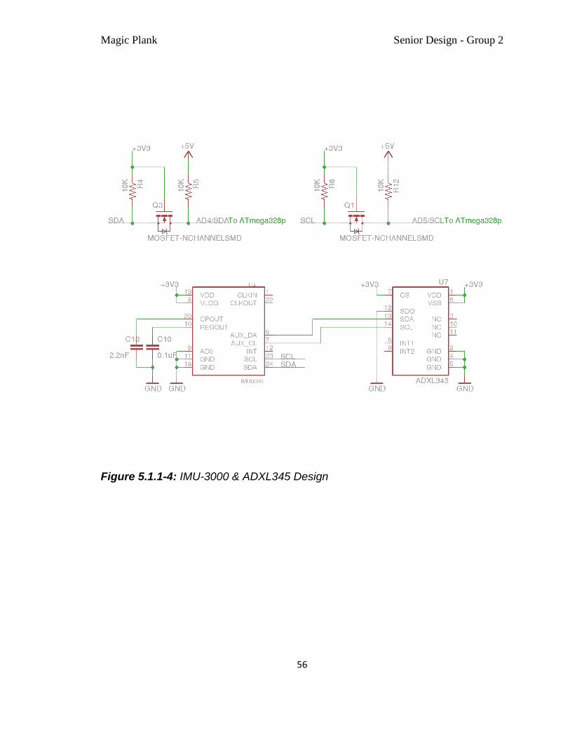
Magic Plank Senior Design - Group 2
56
Figure 5.1.1-4: IMU-3000 & ADXL345 Design

Magic Plank Senior Design - Group 2
57
Figure 5.1.1-5: Bluetooth RN-42 Design

Magic Plank Senior Design - Group 2
58
5.1.2. Motor Controller: Sabertooth 2x25
Our motor controller, the Sabertooth 2x25 Regenerative Motor Driver from Dimension Engineering, is the larger equivalent to our prototype’s 2x12 Regenerative Motor Driver. The main difference between the two is that the 2x25 is able to support up to 25A continuous current at 50A peaks with 24V nominal voltage up to a 30V maximum voltage versus the 2x12’s 12A continuous, 25A peak current with 18V nominal, 24V maximum voltage. The reason for switching to a larger motor controller is due to the larger power draw from the motors. The motor controller needs to be able to handle at least 250W motors operating at up to 24V with up to 18A current draw.
From a software perspective, both Sabertooth motor controllers use the same communication protocols, so any software design that applies to one naturally applies to the other. Configuration of the motor controller is done via the 6 Dual In-line Packages (DIP switches) located on the controller. DIP switch configuration is identical for all Sabertooth motor controllers. Switches 1 and 2 determine which mode in which to operate the motor controller: mode 1 for analog input using Pulse-Width-Modulation (PWM) signals, mode 2 for R/C input, mode 3 for simplified serial, and mode 4 for packetized serial. Switch 3 is for lithium cutoff mode: down when using lithium supplies and up when using other conventional battery supplies such as Lead-acid, NiCd, or NiMH. Lithium cutoff mode is used to prevent the lithium battery from being depleted too much and causing potential damage. The functions of switches 4-6 vary depending on the configuration of switches 1 and 2. For reasons explained in the Motor Controller subsection of the Software Design section, we will be using serial communication. There are 2 supported types of serial communication: simplified serial and packetized serial. Simplified serial mode is done by configuring switch 1 to the up position and switch 2 to the down position. Switches 4 and 5 determine the baud rate at which to operate, which can be 2400, 9600, 19200, or 38400. Switch 6 is either up or down for either standard mode or slave mode, respectively. Packetized serial mode is achieved by setting switches 1 and 2 to the down position. In packetized serial mode, switches 4-6 determine the address of the motor controller ranging from 128 to 135. The address can be configured so that multiple motor controllers can share the same serial transmitter. In terms of wiring, the motor controller is powered directly from the battery and contains a built in 5V 1A regulator capable of powering the microcontroller. Since it is a dual channel motor controller, it has dedicated terminals to each of the two motors. Input commands are obtained from the controller’s inputs S1 and S2, where, in the case of simplified serial input, S1 receives commands from the microcontroller. S2 is not used, but it is still necessary in order to establish a connection. S1 will be running to the ATmega328’s digital pin 19, while S2 will be connected to digital pin 18. Power is obtained through the 5V regulator’s

Magic Plank Senior Design - Group 2
59
connections to VCC pin 7 and GND pin 8. An illustration of the interface between the motor controller and microcontroller is detailed below in Figure 5.1.2-3.
Figure 5.1.2-3: Wiring configuration between the Sabertooth 2x25 - ATmega328
5.1.3. Body Design
The main body design for this platform is fairly simple on the surface: A piece of material to stand upon with 2 chain driven wheels on the bottom driven by 2 250W brushed DC electric motors. The motor controller and other electronics described in the previous sections are housed in the center of the board in between the 2 12V 7mAh batteries. The batteries are connected to each other via a high load power switch, which turns the entire system on or off, as seen in Figure 5.1.3-1 and Figure 5.1.3-2. Unlike the traditional style design of the Segway Personal Transporter, there is no scooter-like steering column because steering has been replaced by wireless control from the Nintendo Wii wireless remote controller. Removal of this steering column lightens the load and cuts down on cost significantly, but reduces the driver’s ability to stand on the platform comfortably. With this in mind, the orientation has been shifted from front-facing to side-facing in the style of a skateboard. Instead of leaning forward or backward to move, the driver leans side to side, allowing the driver to more easily balance on top of the platform while it is in motion.

Magic Plank Senior Design - Group 2
60
Figure 5.1.3-1: Main body diagram, top view
Figure 5.1.3-2: Main body diagram, bottom view

Magic Plank Senior Design - Group 2
61
5.2. Software System: Overview
5.2.1. Operational Concepts: Needs, Scenarios, Limitations, and Risks
Our self balancing transportation platform’s software system will have to address the issues brought forth when solving both an inverted pendulum problem and a locomotion problem. The most basic need satisfied by the system is that of balancing itself on two wheels, which is done by analyzing input from the accelerometer and gyroscope, processing it, and telling the motor controller how to react. The microcontroller must make updates to the motor controller in a timely fashion; otherwise the balance correction would occur too late and cause the platform to collapse. These corrections need to also be accurate, lest the platform collapse due to dramatically overshooting or undershooting the ideal state of being level. The secondary problem addressed by this system is the problem of motion. The platform must be able to move forward, backward, and make turns while still satisfying the primary need of staying balanced. The basic control scheme is achieved wirelessly via input commands from a Bluetooth device that feeds directional data to the microcontroller. The system must, in addition to preserving its own balance, must also serve the driver, who will be standing on the self balancing platform. This means that the system must be user friendly, so the control mechanisms must be smooth enough to not throw the driver off of the platform during operation. As a precautionary safety measure, we may also include a switch that the driver must always have pressed down; in the event that the driver falls off, this “dead man’s switch” is rendered inactive, causing the system to shut down.
Implementing this software system requires us to account for several operational scenarios. The first scenario is that of idle balancing, where the platform has nothing to worry about except keeping balance. There are no external forces attempting to throw it off equilibrium and the platform simply tries to achieve the ideal state of being level. This is the simplest scenario and the first step in development of the system. The second scenario is the case where either the driver or something else is imparting an external force upon the platform, thus changing its center of gravity and upsetting its equilibrium. In this event, the system must attempt to keep its equilibrium and counteract the upsetting force. This requires a more refined control scheme that will keep the platform from either over- or undercompensating, which would have resulted in either the upsetting of the driver or the collapsing of the platform altogether. Another scenario is the scenario where the driver tries to input motion commands to make the platform either move or make turns. This carries the added challenge of fusing the balancing control scheme with the motion control scheme. This may be counter-productive to the primary objective of simply maintaining balance, but the second goal of locomotive ability supersedes the first goal and imposes the offsets necessary to create movement. This means that we must limit the ability of the secondary control scheme to upset the system’s absolute equilibrium by introducing governors that prevent the system from causing the platform to
Magic Plank Senior Design - Group 2
62
collapse. Should we choose to adopt the added safety measure of a “dead man’s switch” attached to the platform, there is the scenario where the driver lets go of the switch. In this scenario, the switch would no longer be active, signaling for the system to halt all operations of the platform. The mechanism handling this scenario would be considered a top priority safety mechanism, and as such it supersedes the lower goals at all times. There are still other scenarios such as hardware failures or physical shortcomings where balancing the platform is impossible, but these external failures are beyond the control of the software system, and the best attempt to account for these scenarios lies in the use of the “dead man’s switch” as a catch-all safety mechanism.
The features present in this system could be ranked in terms of priority and in terms of whether or not the feature is either essential or desirable. The first and most important feature of the system is the ability to balance while idle. Without this feature, the self balancing platform is not much of a self balancing platform. The second most important feature is the ability to balance while moving or when an external force attempts to upset its equilibrium. The third most important goal is the ability to process user input and produce motion output. These two goals are still considered essential to the operation of the platform, since the entire purpose of the platform is to move things from one point to another. The fourth goal is the implementation of the “dead man’s switch”. Although it increases safety for the driver, the platform is still able to function without it. As such, it is labeled as a desirable feature.
Our system does have its limitations. It cannot keep balance in absolutely every situation and it cannot recover from hardware failures. We can attempt to recover balance through the implementation of governors, but there is still a physical limitation of the hardware that prevents the platform from balancing under extreme conditions. Other hardware limitations involve the speed of the microcontroller, the speed at which the accelerometer and gyroscope send commands, and the speed at which the motor controller can receive commands. However, since hardware failures are beyond the scope of the software system and impossible to circumvent, we have no need or ability to develop measures of addressing said failures. The system also has some shortcomings that produce a risk for the user. Even though we plan to implement governors and a possible “dead man’s switch” for safety, it is not guaranteed that the control mechanism is smooth enough to keep the driver balanced on the platform. In this event, the driver could fall off and be injured. With this possibility in mind, we will strive to make the software system as user friendly as possible in order to take every possible measure to prevent injury from occurring.
5.2.2. Project Management
This software system will be co-developed by our Senior Design team’s software designers Brian Jacobs and Kenneth Santiago Jr. There is no hierarchical structure, rather the team works in parallel on individual software implementation

Magic Plank Senior Design - Group 2
63
and combines the work into a framework that will form the entire system. Division of responsibilities is as follows:
Brian Jacobs:
Development of drivers for the motor controller
Development of drivers for the Accelerometer and Gyroscope
Creating a control scheme that balances the platform based on processed data
Incorporation of the “dead man’s switch”
Kenneth Santiago Jr.:
Development of drivers for the Bluetooth device
Development of drivers for the control device that is input via Bluetooth
Modifying existing control scheme to make the platform move based on the control device’s input.
While the other member Stephen C Fraser II may contribute to the development of the project, his primary responsibility is hardware design, and as such, he will spend the majority of his time configuring the physical aspects of the platform. In addition to the explicitly defined roles of the team, we have an explicit definition of communication between developers. The team will meet in person at least twice weekly to discuss code modifications and to keep each other understanding how the code works. They will test each other’s work during these meetings in order to maintain a high standard at all times.
This leads us to our software implementation process, which is commonly known as the waterfall model. The waterfall model calls for each previous stage to be completed before moving on to the next stage. After completion of a coding stage, the work “flows down” to the next stage, building on the previous stage which does not change. This may seem like a rigid structure to adopt, but design of this system is an inherently rigid process. We must be confident that the system will work, and if the initial stages of the project are not complete and thoroughly tested, we cannot move on to the next part of the process. Following this implementation process will allow us to create a reliable system with minimal backtracking, thus minimizing the time spent redoing old code that should have worked in the first place.
5.2.3. Software Architecture and Design Issues
Our architectural approach is to use a layered approach to create basic control structures for each of our devices. The idea is to work from the bottom up, starting with modules that have no dependencies, then building on top of those modules to create another layer of functionality. There are only three main layers to this code: the bottom layer of drivers that have direct interaction with the hardware devices, the middle layer of processing modules that take the hardware interfacing modules and interpret them to create valuable data, and the top layer,

Magic Plank Senior Design - Group 2
64
which is the control structure for the whole system. The bottom layers can be grouped into three main blocks: Motor Controller, Inertial Measurement Unit (IMU), and Bluetooth Controller. The Motor Controller block, which is the only output of the system, handles commands from the main control and converts them into commands understandable to the motor controller. The IMU block contains the Accelerometer and Gyroscope drivers that read the raw data from the hardware, which is then passed into the module on the next level up for processing. The upper level of the IMU block then processes the data into a useful format for the main control loop on the top level. The Bluetooth Controller block contains two pieces: the bottom level driver module, which handles the connection with the device and relays the connection to the upper level for interpretation, and the upper level interpreter module, which takes the input and parses commands from the controller that is wirelessly connected to the device. Once the commands are parsed, they are sent to the top level control in a format readable to the main control. Below, in Figure 5.2.3-1 is an illustration of the architectural design of the system.
Figure 5.2.3-1: Overall Architectural Layout
The main reason for a small number of layers is that of performance, since performance is our utmost concern for this system. Using more layers with complex structures makes the code easier to comprehend and easier to implement, but it comes at the cost of more overhead, and since we are developing in a restricted environment with the limitations of the ATmega328, we need to make our code run as efficiently as possible. Efficient code of course means that the system is able to respond quickly by doing fewer instructions over less time, which also translates into improved power efficiency. However, performance is not our only goal; we also need to make the code maintainable. This is where the layers come in. With each subsection of the system isolated into its own library, we can parse through the code more easily than we could

Magic Plank Senior Design - Group 2
65
one large jumbled master file, which makes both writing and understanding the code much easier.
In addition to our performance and maintainability interest, we chose this architectural style because it is easily testable due to its parallel nature. Each of the lower level modules can be tested independently and can be verified without reliance on the other systems. This allows us to develop multiple modules simultaneously, or develop a module while testing another. Since we share a single hardware device, being able to work on one code section while someone else uses the hardware to test another code section is a significant time saver. Once the module has been tested thoroughly, it can then be incorporated into the design, creating a building block on which the upper levels can rest. This continues until we are ready to code the main control loop, which can depend on the lower level modules to do their jobs.
One unfortunate drawback of the design is that it is not very portable to other platforms should we choose to abandon development on the ATmega328 and switch to another microcontroller with little notice. The hardware drivers are specific to our particular configuration and are difficult to generalize. Generalization can be done, but at an increased performance hit due to adding another layer of functionality that basically takes all the hardware specifics and puts them into a module or series of modules. However, we are relatively confident in our decision to use the ATmega328 and do not see this portability issue as cause for concern.
5.2.4. Development Environment and Hardware Interfacing
Software for our self balancing platform will be developed using the Arduino programming language, which is a Wiring-based language that is syntax compatible with the ISO/IEC C and C++ programming languages. The Arduino Integrated Development Environment (IDE) will be compiling and loading code onto the ATmega328 microcontroller from Atmel. We intend to use this environment to develop a series of control schemes that will allow us to realize our balancing platform. During prototyping, the microcontroller is mounted on the Arduino Uno R3 development board. Since pin numbers in the code correspond to the Arduino’s pin numbers and not the microcontroller’s, translation of pin locations is necessary in order to understand which pin we will be actually connecting to on our custom developed board.
In order to interface with our three devices, we will be using the ATmega328’s UART pins 2 and 3 (Arduino pins 0 and 1) for interfacing with the Bluetooth module, digital pins 18 and 19 (Arduino pins 12 and 13) for interfacing with the motor controller, and I2C pins 27 and 28 (Arduino pins A4 and A5) for interfacing with the accelerometer and gyroscope. Further details regarding the physical connections are located in the Hardware Design section, while the reasons behind these particular pin choices are in the following subsections for software
Magic Plank Senior Design - Group 2
66
design of each individual component. With the physical pin addresses known, we can now move on to the development of our individual components.
5.3. Software Design
5.3.1. Motor Controller
The most basic part of the software control scheme is developing drivers that deliver commands to the motor controller. The Sabertooth 2x12 and 2x25 motor controllers use a variety of control schemes, most notably including the digital packetized serial mode and analog Pulse-Width-Modulation (PWM). Our microcontroller, the ATmega328, supports both PWM and standard serial input ports. Our first inclination is to use PWM, since this control mechanism is the simplest to implement. However, after researching further details on how to use PWM to interface with the motor controller, we discovered that PWM suffers from noise errors due to interference from the motors. In light of this discovery, we have decided to stick with the more reliable digital serial input to drive the motor controller. Sabertooth motor controllers are configurable via Dual In-line Packages, (DIP switches). The DIP switch configuration is detailed further in the Motor Controller subsection of the Hardware Design section. In short, the motor controller is configured in either mode 3: simplified serial or in mode 4: packetized serial. Serial communication to the Sabertooth motor controller is done using 8-N-1 protocol: 8 data bits, no parity bits, and 1 stop bit.
Arduino already provides us with a powerful set of tools for use in serial communication, among which are the HardwareSerial and SoftwareSerial libraries1. The HardwareSerial library establishes a connection via UART input and output pins RX and TX, while the SoftwareSerial library is capable of utilizing any of the digital pins to establish a serial connection. In the case of the motor controller, we can use either of these libraries. However, the ATmega328 is limited to only a single set of hardware UART pins, and since we intend to use those pins on the Bluetooth module, we will be using a software serial connection for the motor controller. The SoftwareSerial library works by establishing a virtual UART connection across the desired digital input and output pins. A connection can be established by making an object of type SoftwareSerial. The constructor takes in a receive pin and a transmit pin. To connect with our motor controller, we will be using pins 18 and 19 (pins 12 and 13 on the Arduino Uno R3).
The first mode we will be exploring is simplified serial2. In simplified serial mode, the commands are in the form of single bytes. The value of the byte determines the command: sending the value 0 shuts down both motors; sending a value from 1-127 controls motor 1; sending a value from 128-255 controls motor 2. The lower values (1 for motor 1 and 128 for motor 2) signal the motors to go in full reverse, while the upper values (127 for motor 1 and 255 for motor 2) signal the motors to go full forward. Before sending any information, the baud rate must be configured on the Sabertooth’s on-board DIP switches 4-6 in a range from 2400 baud to 38400 baud. We intend to use 9600 baud, which lies in the middle of this

Magic Plank Senior Design - Group 2
67
range. Baud is set on the software side using the “begin” command described in the above code segment and passing in the baud rate. After establishing connection, Dimension Engineering recommends waiting for a short amount of time before sending serial commands to the controller. We can write to the connection using either the “print” command and specifying the data type as a byte, or the “write” command which will take a single raw byte of data and write it to the connection.
After initialization, sending commands to the motor controller is as simple as sending single bytes corresponding to a motor command. The byte is split in half, reserving the lower half for motor 1 and the upper half for motor 2. Each half is then split in half again, the lower extreme being the command for full reverse and the upper extreme for full forward. For instance, to drive both motors full forward, we would simply write a speed value of 127 for motor 1 and a value of 255 for motor 2. Similarly, full reverse would be 1 for motor 1 and 128 for motor 2. Writing a command to the motor controller is as simple as using the “write” command and using the corresponding values detailed above. This property makes simplified serial a very easy and efficient option.
The second mode of serial communication is packetized serial2,3. A packet consists of an address byte, command byte, a data byte, and a checksum of 7 bits. The Address byte ranges from 128 to 135, which allows for multiple controllers to be connected on the same serial line. However, we only have need for a single controller, so the address 128 is sufficient. The command byte interprets 17 different commands. Sending a command of 0 or 1 will drive motor 1 forward or backward, respectively. The same applies for a command of 4 or 5 for motor 2. Command 2 sets a minimum voltage for the battery connected to the Sabertooth. If the voltage drops below a certain value, the controller shuts down. There are also mixed mode commands, which affect both motors in a single command. Command 8 is for driving forward, command 9 is for driving backward, and commands 10 and 11 are for turning right and left, respectively. Commands 3, 6, 7, and 12-17 are irrelevant for our purposes. The third byte in the packet, the data byte, contains data relevant to the command. For driving forward, backward, or turning in mixed mode, data ranges from 0 for full stop to 127 for maximum speed. For setting minimum voltage, data ranges from 0 to 120, where value = (desired voltage – 6) * 5. The final packet is the checksum, which is sent to prevent data corruption. The checksum can be calculated as checksum = address byte + command byte + data byte. The checksum is a 7 bit value, and since the ATmega328 is an 8 bit system, the checksum must be ANDed with 0b01111111. Baud rate in packetized serial mode, unless otherwise specified, is at a default of 9600. Establishing communication is relatively the same for both packetized and simplified mode, but now we can no longer simply use the “write” command to send a command to the motors. We now have to send it in the form of a packet by sending the address, the command, the data, and the checksum all sequentially.

Magic Plank Senior Design - Group 2
68
Regardless of the serial mode, the properties of moving a motor can be encapsulated into a single object that handles direct communication with the motor controller and provides an easier interface for higher level processes. Sparing the details behind the process, the final interfacing function for writing to the motor controller can be configured to take in a char for each motor ranging from -127 to 127, which would correspond to a range from full reverse to full forward. This could be represented as a function called “MoveMotors” for example. Note that there is a loss of resolution using simplified serial mode. Even though the function takes in a range of 255, the motor controller is only capable of working with a range of 127 for each motor. In this case, packetized serial has the advantage of being able to operate within the larger range, producing a more granular control scheme. With the control method encapsulated as this singular function, we have something that is easily usable to the top level control module. Now all we have to do is bind these functions into a single object.
Now the top level control mechanism is able to easily communicate with the Sabertooth motor controller by simply instantiating a new Sabertooth object and calling the movement function to move each motor. From the upper level module’s perspective, it is irrelevant whether or not the Sabertooth class is communicating via simplified serial or packetized serial; all backend functionality is handled within the class. This completes our design of the Motor Controller module, which satisfies the most basic needs of the main control scheme.
Before continuing, though, we must analyze which serial mode we should use. Simplified serial is very easy to implement and very lightweight. There is little overhead in communicating with the motor controller, as the information is sent as a single byte. However, there are two main disadvantages for this mode. First, there is no error checking, so corrupted data can still be interpreted as an undesired command. This is opposed to packetized serial’s checksum, which causes the packet to be thrown out if it is corrupted, causing the motor controller to simply continue with the previous command. Second, the commands sent in simplified serial suffer from reduced resolution in an attempt to accommodate commands for both motors in a single byte. Packetized serial is capable of sending a byte reserved for one motor with full range for either a forward or backward command. Packetized serial also has the advantage of differential drive mode, which operates both motors simultaneously. This is potentially advantageous for the upper level control module, which can operate using more simplistic commands. Despite the increased overhead of sending commands via packetized serial, the increased granularity of commands seems to place packetized mode as our preferred method of communicating with the motor controller.
5.3.2. IMU – Raw Data Fetching
The ATmega328 and IMU-3000 will be communicating via I2C interface, which is supported on pins 27 and 28 (Arduino pins A4 and A5). I2C communication is set up in the Arduino development environment using the Wire library1. This creates

Magic Plank Senior Design - Group 2
69
a Two Wire Interface (TWI) establishing a data line (SDA) and a clock line (SCL). Unlike the SoftwareSerial library, we do not instantiate any new data types. There is already an object ready called “Wire”. Establishing communication is done with the “begin” command. Sending a transmission requires initialization via “beginTransmission”, which sends the initial address for transmission, using “send” to send data, and ending with “endTransmission”, which sends the NACK on the I2C bus to terminate communication. Since this is such a common task, future code references will refer to this function as “write_I2C” for any necessary writing.
Now, to receive information from the interface, we can start by requesting information with the function “requestFrom” and specifying the address of the device along with a quantity of information. We also must test to see if the wire is available for use, so we use the “available” function. If the wire is open for use, we can then obtain data via the “read” command. This is also a common task that future code references will simply refer to as “read_I2C”. With transmission and receiving established, we must now determine how to communicate to the accelerometer and gyroscope, which requires that we know the addresses of the items with which we wish to communicate. The relevant addresses are described in Table 5.3.2-1.
Device Description Type Address (hex)
IMU-3000 Gyro address R 0x68
ADXL345 Accelerometer address R 0x53
X_OFFS_USRH / X_OFFS_USRL Gyro X offset high / low R/W 0x0C / 0x0D
Y_OFFS_USRH / Y_OFFS_USRL Gyro Y offset high / low R/W 0x0E / 0x0F
Z_OFFS_USRH / Z_OFFS_USRL Gyro Z offset high / low R/W 0x10 / 0x11
FIFO_EN FIFO enable R/W 0x12
INT_STATUS Interrupt status R 0x1A
GYRO_XOUT_H / GYRO_XOUT_L Gyro X out high / low R 0x1D / 0x1E
GYRO_YOUT_H / GYRO_YOUT_L Gyro Y out high / low R 0x1F / 0x20
GYRO_ZOUT_H / GYRO_ZOUT_L Gyro Z out high / low R 0x21 / 0x22
AUX_XOUT_H / AUX_XOUT_L Accel X out high / low R 0x23 / 0x24
AUX_YOUT_H / AUX_YOUT_L Accel Y out high / low R 0x25 / 0x26
AUX_ZOUT_H / AUX_ZOUT_L Accel Z out high / low R 0x27 / 0x28
FIFO_COUNTH / FIFO_COUNTL Number of bytes in FIFO R 0x3A / 0x3B

Magic Plank Senior Design - Group 2
70
FIFO_DATA FIFO data R 0x3C
USER_CNTRL User control (resets, enables) R/W 0x3D
PWR_MGM Power management R/W 0x3E
Table 5.3.2-1: IMU-3000 & ADXL345 Addresses2,3
We are presented with several options in interfacing with the IMU-3000. First, the gyroscope and accelerometer data are always available through the outputs at addresses 0x1D-0x28, which is the most direct way of accessing these values, so we will explore this option first. We can start by requesting 12 bytes of data starting at address 0x1D, which is the start of GYRO_XOUT_H, and ending with AUX_ZOUT_L at address 0x28. This begins by transmitting to address 0x68 (IMU-3000’s I2C address) and setting the start address to 0x1D. Once we initialize the register value to start from, we can start fetching the values from the device. These values can be stored into a buffer until we are finished reading. Reading is done in the format of the most significant byte (high) followed by the least significant byte (low). We can continue reading until the device is done sending the requested data, upon which we end transmission.
After the 12 byte fetch is complete, we can read those values from the buffer and combine the bytes into integers. This formats the 12 byte sequence into relevant data for each axis of the gyroscope and accelerometer. Data comes in the order it was requested, starting with 0x1D for the MSB of the x axis of the gyroscope, 0x1E for the LSB, etc. Reading the data in this way is simple, but there is yet another way to do it: the FIFO
Utilizing the FIFO requires a slightly more advanced approach. The first thing we must do is become familiar with the FIFO_EN, or FIFO enable register, at address 0x12. It contains 8 bits that correspond to an output value to be stored in the FIFO. Setting each of these bits controls what data gets put into the FIFO by the IMU-3000. For example, writing a value of 0b01111111 enables all data except the temperature.
Bit7 Bit6 Bit5 Bit4 Bit3 Bit2 Bit1 Bit0
TEMP_OUT GYRO_XOUT GYRO_YOUT GYRO_ZOUT AUX_XOUT AUX_YOUT AUX_ZOUT FIFO_FOOTER
Table 5.3.2-2: FIFO Enable Register 0x123
Second is the usage of the User Control register at address 0x3D. This register, when written to, will enable or reset certain parts of the IMU-3000. We must set both the FIFO_EN and FIFO_RST bits by writing the value 0b01000010. Setting the reset bit then allows us to write to the FIFO_EN register and change the value to output the desired data. We must then disable the reset bit once we have configured the FIFO_EN register.

Magic Plank Senior Design - Group 2
71
Bit7 Bit6 Bit5 Bit4 Bit3 Bit2 Bit1 Bit0
DMP_EN FIFO_EN AUX_IF_EN - AUX_IF_RST DMP_RST FIFO_RST GYRO_RST
Table 5.3.2-3: User Control Register 0x3D3
Initializing the IMU-3000 for FIFO reading would be similar to the following:
write( 0x68 , 0x3D , 0b01000010 ); //Write to User Control: FIFO_EN / FIFO_RST write( 0x68 , 0x12 , 0b01111111 ); // Enable all data except temperature write( 0x68 , 0x3D , 0b01000000 ); // Write to User Control: disable FIFO_RST
The next register we must familiarize ourselves with is the FIFO_COUNT registers 0x3A and 0x3B. These registers store the number of bytes of valid data that are in the FIFO, which is a maximum of 512. In the event that the FIFO fills up, the length reads 512. Old FIFO data is pushed out to make room for new data, so data is never too old. A FIFO reset should be considered if there is an overflow. Getting this value will allow us to burst read data from the FIFO, which saves computation time.
Register Bit7 Bit6 Bit5 Bit4 Bit3 Bit2 Bit1 Bit0
0x3A - - - - - - FIFO_COUNT_H
0x3B FIFO_COUNT_L
Table 5.3.2-4: FIFO Count Registers 0x3A and 0x3B3
Data is read from the FIFO in the following order:
TEMP_OUT 2 bytes Temperature high/low GYRO_XOUT 2 bytes Gyroscope X high/low GYRO_YOUT 2 bytes Gyroscope Y high/low GYRO_ZOUT 2 bytes Gyroscope Z high/low AUX_XOUT 2 bytes Accelerometer X high/low AUX_YOUT 2 bytes Accelerometer Y high/low AUX_ZOUT 2 bytes Accelerometer Z high/low FIFO_FOOTER 2 bytes Footer, last read operation
The Gyro and accelerometer readings are the same as reading directly from the registers. (MSB first, followed by LSB), but here we have two extra pieces of data: TEMP_OUT, which is the temperature reading, and FIFO_FOOTER, which is just a spacer in between FIFO data blocks that is left over when a read occurs. There is one advantage to setting up the FIFO, which is the ability to toggle which inputs we need. We can completely eliminate the axes that are irrelevant to us, saving time that would otherwise have been wasted reading useless data. Since we have disabled temperature readings, we need only fetch 14 bytes of data per block. With knowledge of the FIFO size through the use of FIFO_COUNT, we can burst read all the data at once. However, before doing a complete FIFO read, it is recommended that the FIFO input be halted, followed by a complete read of 512 bytes, then re-enabling the FIFO.

Magic Plank Senior Design - Group 2
72
Now we must address the issues associated with utilizing simplified output or using the FIFO to get burst readings. Getting burst readings is potentially advantageous and could save valuable computation time if implemented correctly, but it is a radically different programming approach than using sampling when needed. Using large amounts of cached data is an intensive process that is likely beyond the scope of our 16MIPS ATmega328 microcontroller. The microcontroller could theoretically handle burst processing, but at the instruction throughput rate, it is likely that the data could be too old and therefore rendered irrelevant by the time it needs to be used. With regular sampling, the microcontroller is always getting the most current values and therefore has a more reliable output. Keeping this in mind, we have still decided to move forward with the standard sampling directly from the registers, but still keep in mind the possibility of doing burst reading through the FIFO. At this stage in development, it is too early to entirely rule out one possibility. However, since we will initially be doing standard sampling, we can now develop a class that fully encapsulates this design. It is capable of initializing the IMU-3000 and reading its inputs, storing them into integer representations that are easily and readily accessible by the upper level module.
Now that this module is encapsulated into something that is usable to an upper level, the bare hardware interfacing between the microcontroller and the IMU-3000 is no longer a concern. The upper level module only has to worry about processing this data and making it usable to the top level control module.
5.3.3. IMU – Raw Data Processing
Now that the raw data has been extracted from the accelerometer and gyroscope, all that is needed is to process the data into a usable format. The ADXL accelerometer gives data in the form of gravitational force at a precision of +/- 2g’s in the form of a 16 bit 2s complement binary number. Although it is represented as 16 bits for convenience of the processor, its maximum resolution is 14 bits. The gyroscope located inside the IMU-3000 measures data in the form of degrees per second, of which it will be configured for +/- 250 deg / sec expressed as a 16 bit 2s compliment binary number. The basic idea behind processing this raw data is to fuse the accelerometer’s gravitational force rating with the gyroscope’s degree reading so that the data processed corresponds to the state of motion of the system in terms of angle and angular velocity. The raw data output by the hardware must first be normalized pre-processing. This simply involves taking some samples while the IMU is level and at rest, then figuring out a constant at which to multiply the raw readings such that the data zeroes out. The 16 bit integers are thereby converted into floats during this process. After offsetting comes filtering; there are two main approaches to processing the data: the complementary filter and the Kalman filter1.
The first and simplest approach, the complementary filter, is one of the most common ways to process the raw data. A complimentary filter works by managing both a low pass filter for high frequency signals from the
Magic Plank Senior Design - Group 2
73
accelerometer and a high pass filter for low frequency signals from the gyroscope. A low pass filter is needed due to the nature of the accelerometer. Vibration causes small spikes in acceleration that are not desirable, so a low pass filter generally takes care of the small insignificant spikes and only cares about the changes caused by true acceleration. A high pass filter is needed for the gyroscope due to a problem known as gyroscopic drift where the gyroscope outputs small changes reflected by imperfect sensors. Filtering begins with the definition of a constant K (which is simply determined to be a nice number that is specific to the design) and a loop time L (which is the time it takes to sample the data in seconds). There are two different techniques for doing a complimentary filter: the first order filter and the second order filter.
In the first order filter, K is usually a small number between 0 and 1. Calculation on the first order can be done in a couple lines, first by averaging out the constant K and loop time L into filter constant F, then by multiplying F with the sum of the current angle, new accelerometer rate, and L and adding it to the complement of F times the new gyroscope angle2. The resulting calculation is a simple low and high pass filter that smoothes much of the undesired raw data values.
The second order filter is accomplished by setting constant K to some number not necessarily between 0 and 1. The difference of the new angle and the current angle is multiplied with the square of K, then loop time L is summed with the difference of the new angle and the current angle multiplied by 2K and then added to the new rate. These values are multiplied by L and added to the current angle. This results in a slightly more complicated low and high pass filter that delivers slightly better results.
The second approach is the Kalman filter, which is largely regarded as the best approach to the problem. The only drawback is that this is a very complex algorithm that is not easily understood. This means that a pre-defined library must be extensively utilized. In addition to reliance on libraries, this filtering technique requires a large amount of processing power, and since the ATmega328p is limited in its instruction throughput, the filter’s theoretically superior results could be outweighed by its performance impact. Creating a Kalman filter requires configuration of three main constants: The 2nd moment E(α2), E(bias2) and measurement process noise covariance Sz.
3,4 These constants are processed through matrix math in addition to the current filter value, the new acceleration rate measurement, and the new gyroscope angle measurement. In short, comprehending the particulars about the filter are irrelevant so long as the library is general enough to be usable. There is a wealth of knowledge on Kalman filter libraries, including free to use Arduino code that is readily accessible, so building a Kalman filter from the ground up is completely unnecessary.

Magic Plank Senior Design - Group 2
74
In order to decide which filtering method is superior requires some analysis on the filtering values. According to analysis done by Walter T. Higgins Jr. of Arizona State University, the complementary filter performs comparably to the Kalman filter, though the Kalman filter does strictly give the best performance due to reduced response to vibration noise. However, due to increased computational complexity, real-time performance on a restricted system is potentially lower than the simpler and faster complementary filter. The overall consensus seems to be that the complementary filter is a “good enough” approach that saves a lot of valuable computation time, so at this point in time, the current approach will be using a complementary filter. The Kalman filter will still be supported and developed in the event that the complementary filter does not perform well enough.
Regardless of the filtering method, this module can be summarized with the creation of a function taking in the accelerometer’s newest angle and the gyroscope’s newest rate. The function would also need constants that vary depending on the filtering method used. Constants and background methods can be summarized in a single class.
With these operations summarized into a single module, the top level control module can easily operate the filter without any knowledge of the lower level’s backend functions. This modular approach provides an easy way to modify the filtering method without interfering with or invalidating the rest of the code.
5.3.4. RC Coding Implementation
The communication between the Nintendo Wii wireless remote controller and the development board being used (be it the Arduino development board for the prototype or the Atmel ATmega328p processor development for the final project) will only need to be one way, as the Nintendo Wii wireless remote controller will only be needing to transmit the data relating to the orientation of the controller from the internal accelerometer and the pressing of any of the buttons to the development board and will not be required to receive any information in order to perform that task. The Nintendo Wii wireless remote controller is set up to be defaulted in a mode (0x30) which will transmit only the output of the status of the core buttons. For use in the project at hand, the mode represented by the bits (0x31) will be used, which will transmit output from both the core buttons and the accelerometer. This mode will be accessed through a SET_REPORT request through channel 0x12 via the following command:
(a1) 12 00 31
There have been many different libraries that have been developed specifically for developing programs revolving around the Nintendo Wii wireless remote control due to the uniqueness of its design, as well as how simple the device is to interface with due to its basic Bluetooth transmission capabilities. The library pack which has been utilized is known as LibWiiMote-0.4, developed by Joel

Magic Plank Senior Design - Group 2
75
Andersson. The library is very vast, as it contains a basic setup for whether the application would be reading information from the Nintendo Wii wireless remote controller or if would be sending information to the controller; however, what it contains regarding the ability to read information from the controller was designed in such a way that would make it suitable to the prototype’s and project’s needs. A flowchart of the interaction between the header files and source files is seen in Figure 5.3.4-1.
The physical link structure that the Nintendo Wii wireless remote controller will utilize to connect with the SMD Module – RN – 42 will have its own specific structure called wiimote_link_t. For the sake of convenience, both the Bluetooth address of the Nintendo Wii wireless remote controller and the Bluetooth address of the local host with which it will be connected to are stored in separate char arrays in the wiimote_link_t struct. Along with the Bluetooth addresses are variables representing the current connection status of the Nintendo Wii wireless remote controller, the local host, the Bluetooth device number, the Human Interface Device interrupt socket, and the Human Interface Device control socket.
The library contains an enumerator list which details the different modes which are supported by the Nintendo Wii wireless remote controller, as was briefly mentioned earlier. The enumerator list can be used both when setting the mode which the Nintendo Wii wireless remote control will be using to transmit data, as well as in the debugging process to be sure that the mode doesn’t change through either faulty code or through an unexpected hiccup. The enumerator names are very intuitive, with WIIMOTE_MODE_ACC representing the value of “0x31” (the mode which contains the addition of the accelerometer data), WIIMOTE_MODE_ACC_IR representing the value of “0x33” (the mode which contains the addition of both the accelerometer data as well as the infrared reports), and similar naming schemes for the remaining mode types. To complete the definition of the different modes of the Nintendo Wii wireless remote controller, the library also contains the definition of a structure specific to the modes. The basic structure for the modes of the Nintendo Wii wireless remote controller contains enable bits for the three non-button outputs of the controller: the accelerometer, the infrared camera, and the extension port.

Magic Plank Senior Design - Group 2
76
Figure 5.3.4-1: Header and source interaction
The other enumerator list that the LibWiiMote-0.4 library pack houses contains values which are used to determine the status of the Nintendo Wii wireless remote controller’s connection to its host. This list is of particular importance, as it not only serves as a way to establish when the controller is able to send commands, but it also provides a method to establish a kill condition which would halt the balancing platform project should the controller no long be linked up.

Magic Plank Senior Design - Group 2
77
Because the Nintendo Wii wireless remote controller only sends new packets of data when the data has changed in some form from the previously sent packet, the throttle of the prototype balance board and the steering of both the prototype balance board and the final balancing platform will continue to be controlled by the last data packet to be sent. While this is convenient in terms of power conservation since the development board will not be required to waste processing time to repeat a command that hasn’t changed, it could also prove to be a rather problematic issue should the Nintendo Wii wireless remote controller suddenly disconnect after sending a command. An example of this potential issue would be if the user had commanded the self-balancing motorized platform to turn to the left at the maximum rate just prior to the Nintendo Wii wireless remote controller running out of batteries, the driver of the scooter would be left spinning in circles as fast as the code allows until the controller either reestablishes a connection via an emergency battery replacement or until the self-balancing motorized scooter is powered off. This potential design flaw further emphasizes the convenience of the enumerated list included in the LibWiiMote-0.4 library pack.
Because the data packet transmitted by every mode available to the Nintendo Wii wireless remote controller includes bytes related to the change in the state of the controller’s button presses, the library contains a structure specific to the controller’s multiple buttons. The format of the data transmitted by the button presses of the Nintendo Wii wireless remote controller is similar to the following example:
(a1) 30 BB BB
As shown above, the state of each button press (represented by the variables BB) is contained within two bytes of data. Each state is then capable of being stored in the wiimote_keys structure by simply defining each state as having a two byte (or 16 bit) data type.
Because the majority of the data that will be processed from the Nintendo Wii wireless remote controller will be information regarding the changes in the orientation of the controller from its internal accelerometer, there will be a need to make heavy use a method in which to keep track of different sets of coordinates existing in 3D space. To accomplish this, the program will be storing the values in structures of type wiimote_point3_t. This particular structure inside the library contains three variables, each representing a different attribute of a location in 3D space. The three variable types are unit8_t x, unit8_t y, and unit8_t z, with each representing a different axis.
The final structure in the library that will be utilized is that which is for the Nintendo Wii wireless remote controller’s data structure which is simply titled wiimote_t. This structure was built to be read directly from a Human Interface Device report. The order in which the variables inside the structure were specifically designed to match up with the order in which they appear from the

Magic Plank Senior Design - Group 2
78
data packet sent out from the Nintendo Wii wireless remote controller, with the first entry being mode of type wiimote_mode_t which contains the current report mode of the controller, the second entry being keys of type wiimote_keys_t in order to house the current key state, the third entry being axis of type wiimote_point3_t, and so forth. This structure will be the core structure through which the data read in from the Nintendo Wii wireless remote controller will be stored, as it will be utilizing the previously mentioned structure types which have been defined above. The wiimote_t structure will also house the previously stored data in another structure called old which will be used in order to detect the change in the data to determine whether the previously transmitted data packet should continue to be followed or if it should be altered to match a more recent packet.
The second library that will be utilized is the wiimote_event.h library. As the name suggests, this library sets the stage for the reception of each data packet transmitted by the Nintendo Wii wireless remote controller. This particular library contains definitions for the bytes which represent all of the buttons on the Nintendo Wii wireless remote controller, as well as definitions which will be used to recognize the masks of the keys and whether they are being pressed down or if they have just been released. These definitions will be able to be used to translate the bits that are transmitted from the Nintendo Wii wireless remote controller as they are parsed into their individual parts so that each command can be deciphered and the appropriate instruction can be sent.
The modes which the Nintendo Wii wireless remote controller can be in which do not include information regarding anything plugged into the extension port in the rear of the controller are referred to as the standard modes. Because these modes all have a similar base of information which they are transmitting with each data packet, it makes sense to have them all contained within the same structure. While there exists a structure within the previously mentioned library, wiimote.h, which will be used to house the specific data pertaining to the activation of any particular output from the Nintendo Wii wireless remote controller, this particular structure, wiimote_std_state_t, will be used to contain the state of each of these features. This structure also utilizes the data types that had been defined in the wiimote.h library in order to be able to properly store the current state of each of the Nintendo Wii wireless remote controller's output.
The final structure that exists in the wiimote_event.h library that the self-balancing motorized scooter project and the balancing platform prototype will be utilizing to allow the Nintendo Wii wireless remote controller to be used as the steering implementation of choice is the wiimote_state_t structure. This structure will be used to house all of the information stored in the previously mentioned library, wiimote_std_state_t.h, for each of the different information transmission modes. This particular data type also happens to be a union, allowing it to be tailored specifically to whatever mode the Nintendo Wii wireless remote controller

Magic Plank Senior Design - Group 2
79
while still being able to be flexible enough to handle any other modes it should be required to utilize.
With the libraries established, the source files could then be created to use these predefined data structures and types. A source file of particular note is wiimote_api.c, which handles the application programming interface used by the Nintendo Wii wireless remote controller. The source file consists of functions which set up the Nintendo Wii wireless remote controller variable, referred to as wiimote and being of type wiimote_t. The source file first establishes the controller’s side of the connection between the Nintendo Wii wireless remote controller and the development board in use. It accomplishes this through several functions. The first of these functions is wiimote_open, which returns data of type wiimote_t.
The function establishes a variable of type wiimote_t called wiimote and then checks for whether the variable was correctly created or not through a simple ‘if’ statement. Should the variable have been incorrectly created or not created at all, the function will return an error of WIIMOTE_NONE to indicate that the variable for the Nintendo Wii wireless remote controller had failed to be created. If the variable was successfully created, the function next checks if there is an active connection between the Nintendo Wii wireless remote controller and the host by comparing the output of the wiimote_connect function with input variables of the newly created wiimote and host with the number zero. Should the output be less than zero, it is indicative of a failure to connect to the host and will result in the return of an error of WIIMOTE_NONE. Should the function managed to get past the two previously mentioned error checks, the bits of the mode attribute of the wiimote variable is initialized to the default mode of reading only in the button values of the controller through the following command:
wiimote->mode.bits = 0x30;
As mentioned earlier, the 0x30 bits are unique to the default, button-only configuration of the Nintendo Wii wireless remote controller’s modes. Following this final declaration of the controller’s default mode, the function then returns the newly updated wiimote.
Another function contained within the wiimote_api.c source file serves the express purpose of simply closing the connection between the Nintendo Wii wireless remote controller and its host, as well as ending the entire session. This function, named wiimote_close of type int, begins with a check to see if there exists a connection between the Nintendo Wii wireless remote controller and a host by simply calling a previously defined function intuitively named wiimote_is_open. If there does exist a connection, the function continues to attempt to close the connection, reporting a WIIMOTE_ERROR if the return value of the function wiimote_disconnect is a negative number when the wiimote variable is passed in as a parameter. If the open connection had been successfully closed or if there never was an open connection to a host to begin

Magic Plank Senior Design - Group 2
80
with, the function concludes by freeing up wiimote so as to completely end the data transfer session, returning a value of WIIMOTE_OK to signify that the transaction to close out the session was a success.
The final function of note in the wiimote_api.c source file, wiimote_copy, is able to copy the data from one wiimote structure into another wiimote structure when the source and destination structures are entered as parameters. The function is simplistic in design, as it simply calls a memcpy on the passed in source and destination in order to make the copy. The function then checks to see if the memcpy call was successful, returning a WIIMOTE_ERROR if the process failed and returning WIIMOTE_OK if everything checked out.
The source file which handles all of the events prompted by the data packets sent by the Nintendo Wii wireless remote controller to its host connection is named wiimote_event.c. This source file is in charge of not only handling the events that occur, but it is also in charge of doing the calculations required to translate the data packets transmitted by the Nintendo Wii wireless remote controller into usable data that’s capable of being used directly to control the steering and throttle of the self-balancing motorized scooter project and The prototype balancing board. The functions described in this source file rely heavily upon the data acquired from the previous source files as most of the data required for its functions are required to already be interpreted; however, raw data taken straight from a transmission from the Nintendo Wii wireless remote controller can still be utilized here.
The first function of this source file is named wiimote_get_state. As the name implies, this function’s purpose is to read in the state (or mode) of the Nintendo Wii wireless remote controller and to save the corresponding bit representation (0x30, 0x31, etc.). The function accomplishes this by checking the Serial port of the development board to see if there’s any data ready to be received and acquiring it if there is. The data is then parsed for the first two bytes of data, which contain the mode of the Nintendo Wii wireless remote controller, and stores the mode in the state variable which had been passed into the function. Upon attempting to acquire the data packet, the function makes a check to see if the acquisition was successful and returns WIIMOTE_ERROR if it failed to do so. If an error didn’t occur, then the function simply returns WIIMOTE_OK.
The function update_mode performs an update on the current information output mode of the Nintendo Wii wireless remote controller in the event that the user wishes to change the mode whilst the device is in use. The function begins with a check to be sure that the mode has actually changed by comparing the last stored bit values of the most recently used mode, stored in wiimote->old.mode.bits, with the newly read bits. Should these two byte values match up, the function simply ends there, returning an indication of WIIMOTE_OK since there is no longer any need to alter the mode of the Nintendo Wii wireless remote controller. Should the case be where the old mode bits do not match up with the

Magic Plank Senior Design - Group 2
81
newly read bits, indicating that a change in the output mode is desired, the function continues to make the necessary changes to the mode based on what the new mode should be.
Following the updating of the mode, the function continues to change the data types stored in the wiimote structure. For example, should the new mode that was chosen be one which includes feedback from the Nintendo Wii wireless remote controller’s infrared camera (indicated by simply checking if both the new mode has the defined bits of ir and the old mode does not), the function proceeds to enable the infrared sensor by checking if the bits representing the WIIMOTE_MODE_ACC_IR mode are set in the current mode in order to determine if the infrared mode should be set to WIIMOTE_IR_MODE_EXP or if it should be set to WIIMOTE_IR_MODE_STD. This same function is also capable disabling the Nintendo Wii wireless remote controller’s infrared sensor. It accomplishes this by first checking to be sure that the old mode stored in old.mode in the wiimote structure is set to the value defined by ir and then checking that the new mode doesn’t have the same value. If both of the previously mentioned conditions have been met, then the function calls the wiimote_enable_ir function but passes through the value WIIMOTE_IR_MODE_OFF, signaling the disabling of the infrared sensor.
The function calc_tilt requires only the input of wiimote structure in order to calculate the tilt of the Nintendo Wii wireless remote controller. It accomplishes this through the use of some trigonometry and the output data from the Nintendo Wii wireless remote controller’s internal accelerometer. The function first begins by establishing a ratio for each of the three 3D plane coordinates x, y, and z, by subtracting the specific calibrated zero standard from the scale factor of each coordinate as shown in the calculation for the x coordinate below:
float xs = wiimote->cal.x_scale - wiimote->cal.x_zero;
Once the ratio has been established, the values of the current accelerometer data for each of the coordinates can then be utilized. The raw values of the data from the Nintendo Wii remote controller’s internal accelerometer are seen in a similar format to those of the standard buttons. An example string is shown below:
(a1) 31 40 20 86 8a a5
It is already know from previous examples that byte zero is the channel through which the information will be transmitted, also referred to as the mode. Bytes one and two are the bitmask for the buttons. Bytes three, four, and five are the related to the x, y, and z axis measurements, respectively. It is this data that is utilized by the next part of the calc_tilt function. The function takes the value from the accelerometer that had been stored in the axis attribute of the wiimote structure and subtracts from it the previously used zero location for the coordinate. The
Magic Plank Senior Design - Group 2
82
resulting number is then divided by the ratio that had been established earlier and is then casted as a float for further calculations, as seen below:
float x = (float) (wiimote->axis.x - wiimote->cal.x_zero) / xs;
The final step of the calculation of the tilt of the Nintendo Wii wireless remote controller is where the trigonometric functions mentioned earlier are put into use. The trigonometric calculation consists of calculating the arcsine of each of the three coordinate values that were derived in the previous equation and converting this answer into degrees by multiplying it by 180 degrees and then dividing it by the value of pi. The equation used is seen in the example below:
wiimote->tilt.x = (asin(x) * 180.0f / M_PI);
As seen in the above equation, these values are then stored directly in the wiimote structure for use in determining how to translate these values into directions which the development board can use.
Similar to the last function, the calc_force function proceeds to calculate the force of the movement of the Nintendo Wii wireless remote controller. The function accomplishes this by simply calculating the difference between a coordinate’s location on its plane of existence and the zero value attributed to that coordinate and dividing that value by the difference between the scale factor for that coordinate and the zero value. An example of this equation is reproduced below.
float force_x = (float) (wiimote->axis.x - wiimote->cal.x_zero) /
(wiimote->cal.x_scale - wiimote->cal.x_zero);
With this new value calculated it is then stored into a variable of type float. This new value is then stored in the wiimote structure in the attributes created specifically to store the force of each of the three coordinates in 3D space.
The next function in the source file wiimote_event.c is the process_state function. This function is responsible for utilizing all of the previously mentioned functions residing within wiimote_event.c in order to put the correct information into the passed in wiimote structure and its accompanying data transmission mode. It accomplishes this through a massive switch statement, varying each case based on the channel which the information shall be traveling (thus dictating the mode). In the case where the channel is the bits defined by WIIMOTE_RID_ISTATUS, the function first initializes the device plugged into the Nintendo Wii wireless remote controller’s extension port. It does this by writing the bytes which the Nintendo Wii wireless remote controller recognizes as then initialization of the extension port, ‘0x04a40040’. Should this process fail, the function then displays an error and returns a value of WIIMOTE_ERROR. The function then reads which type of device is plugged in and stores the information in the wiimote structure, displaying a message if it fails to do so.

Magic Plank Senior Design - Group 2
83
The function continues by decoding the Nintendo Wii wireless remote controller’s Nunchuk attachment if it’s currently attached to the controller. It accomplishes this by calling the nunchuk_decode function prototyped in the wiimote_nunchuk.h library and defined in the wiimote_nunchuk.c source file; however, if the function had previously detected that there was no device currently plugged into the Nintendo Wii wireless remote controller’s extension port, the previous steps are skipped and the wiimote structure is notified of the lack of an extension port device by setting the wiimote’s mode.ext attribute to zero and its ext.id to negative one. The function then concludes the case by resetting the report mode, as the Nintendo Wii wireless remote controller will not send any more data immediately after a status report has been received otherwise. This is accomplished by setting the bits of the old mode stored in the wiimote structure to zero ad then calling the update_mode function and passing in the wiimote
structure to finish the update.
The next four cases in the switch statement, WIIMOTE_MODE_ACC_IR, WIIMOTE_MODE_IR, WIIMOTE_MODE_ACC, and WIIMOTE_MODE_DEFAULT, execute the same code due to their similar outputs. Should the case statement match one of the modes mentioned above, the function starts by handling all of the possible types of data that could be read in those modes. The function begins by converting the infrared data currently stored in the passed in wiimote structure into a standard which can be utilized by a more simplistic function via the conv_ir_std function. Once the potential infrared data has been handled, the function proceeds to copy over the data from the ev structure’s axis attribute to the attribute of the same name in the wiimote structure. The function continues to copy over data from the ev structure to the wiimote structure by transferring the data related to the bits of the buttons recently pressed on the Nintendo Wii wireless remote controller. With the values of the buttons, infrared, and accelerometer copied over, the function then uses the accelerometer data to calculate the tilt and the force of the recent movements of the Nintendo Wii wireless remote controller through the two previously mentioned functions calc_tilt and calc_force before breaking out of the code applied to those specific mode cases.
In the case of the channel being WIIMOTE_MODE_EXT, or having a bit value of 0x34, the function begins by updating the bits of the key attribute of the wiimote structure with those of the passed in ev structure. With the bits updated, the function proceeds to decode the extension data, whose presence is indicated by the bit value of the channel being WIIMOTE_MODE_EXT, held in the ev structure. The decoding is accomplished by simply calling the nunchuk_decode function with the extension data of the ev structure passed in along with the bit size of the data. The function then proceeds to determine which extension is currently plugged in to the Nintendo Wii wireless remote controller through a series of if statements. The first statement checks if a Nintendo Wii Nunchuk is currently attached by comparing the extension identifier attribute, which was recently updated in the wiimote structure, with the bit identifier

Magic Plank Senior Design - Group 2
84
WIIMOTE_NUNCHUK_ID. If the check comes out true, the function simply copies over the data inside the ev structure’s extension data attribute to the wiimote structure’s Nunchuk extension attribute, as well as modifying the bits of the Nunchuk attribute by performing the XNOR operation on it with the value of 0xff. If the channel is WIIMOTE_CLASSIC_ID instead of WIIMOE_NUNCHUK_ID, the function needs only update the extension data of the wiimote structure with that of the ev structure.
If the channel is represented by the bit definition of WIIMOTE_MODE_ACC_EXT, or having a bit value of 0x35, the function is tasked with handling the information received from both the extension port as well as the Nintendo Wii wireless remote controller’s internal accelerometer. The function begins this specific case by transferring the bit data held in the ev structure’s key attribute to the wiimote structure’s same attribute. The function then copies the information in the ev structure’s accelerometer information from the axis attribute to the axis attribute of the wiimote structure. The tilt and force are then both calculated via the calc_tilt and calc_force functions. With the accelerometer data successfully calculated, the function then decodes the ext2 attribute’s data via the nunchuk_decode function. If the extension identifier for the wiimote structure has a value of WIIMOTE_NUNCHUK_ID, the function will then decode the ext1 attribute’s data, followed by copying the newly decoded data into the wiimote structure’s extension specified for the Nintendo Wii wireless remote controller and then modifying the data by once again performing an XNOR operation on it with the value of 0xff. If the extension identifier for the wiimote structure is instead having a value of WIIMOTE_CLASSIC_ID, the function instead updates the wiimote structure’s extension data with that of the ev structure’s.
The next case in the switch statement handles the event where the channel’s bit representation is WIIMOTE_MODE_IR_EXT, indicating that the current mode includes data from the core buttons, ten infrared bytes, and nine extension port bytes. This case begins, much like the other cases, by updating the bits of the wiimote structure’s keys attribute with those of the ev structure’s. Following the bit update, the ev structure’s extension data is once again updated via the nunchuk_decode function. With the extension data decoded and the extension’s bit data transferred over into the wiimote structure, the function begins its check for the type of device plugged into the extension port. If the identifier for the wiimote structure’s extension attribute is the bit definition WIIMOTE-_MODE_IR_EXT, the function proceeds by performing a memory copy from the data in the ev structure’s extension data attribute to the wiimote structure’s Nunchuk extension attribute. Inside the same constraints of the of the ‘if’ statement, the function proceeds to perform an XNOR operation on the stored bits of the Nunchuk keys attribute of the wiimote structure with the 0xff value. The statement is concluded by converting the infrared data once again via the conv_ir_ext function. If the wiimote structure’s extension identifier is

Magic Plank Senior Design - Group 2
85
WIIMOTE_CLASSIC_ID, however, the function updates the wiimote structure’s extension data to reflect the state.
The following case handles the situation where the Nintendo Wii wireless remote controller’s bit identification is the bit definition WIIMOTE_MODE_IR_EXT. This case is handled nearly identically to the previous cases, starting off by updating the bits of the wiimote structure’s key attribute with those from the ev structure. Following that command, the function once again decodes the data in the ext2 attribute of the ev structure for use by the wiimote structure. If the wiimote structure’s extension identifier is the bit identifier WIIMOTE_NUNCHUK_ID, the function copies the data in the ext2 attribute of the ev structure over to that of the wiimote structure pertaining to the Nunchuk attribute. After the data has been copied over, it is once again modified by having an XNOR operation performed on it with the bits 0xff. After the data has been modified, the infrared data in the ev structure is converted via the conv_ir_ext function and moved to the wiimote structure. If the wiimote structure’s extension identifier is, instead, the bits represented by WIIMOTE_CLASSIC_ID, the function instead simply updates the wiimote structure’s data with the ev structure’s.
The final case in the process_state function is where the chosen channel is the bits defined by WIIMOTE_MODE_ACC_IR_EXT, or the bits 0x34. This case begins, just as most of the other cases began, with transferring the bits from the keys attribute of the ev structure into the keys attribute of the wiimote structure. This process is followed by the ext3 attribute’s axis bits from the ev structure being copied over to the bits of the keys attribute of the wiimote structure. The next step this case takes is the function calculating the tilt of the newly copied axis values in the wiimote structure through the use of the calc_tilt function. With the tilt calculated, the function then utilizes the calc_force function to calculate the force of the last movement read through the Nintendo Wii wireless remote controller’s internal accelerometer. Afterwards, the function proceeds to convert the infrared extension data from the ev structure and copy it into the wiimote structure via the conv_ir_ext function. Next, the extension data in the ev structure is decoded through the nunchuk_decode function. The function then makes a check for which extension is being used by first comparing the byte identifier in the ext attribute of the wiimote structure with the byte value defined by WIIMOTE_NUNCHUK_ID. If the two values match, the function then copies the data from the ext3 attribute of the ev structure into the Nunchuk extension data in the wiimote structure. Afterwards, like before, the bits of the Nunchuk extension in the wiimote structure have an XNOR operation performed on them with the bits 0xff. If the two values did not match, the function then compares the byte identifier in the ext attribute of the wiimote structure with the byte value defined by WIIMOTE_CLASSIC_ID. If the two values match in this case, the wiimote_classic_update function is called to bring updated information to the wiimote structure via the ev structure’s data. In the event that none of the cases’ conditions were met, the function assumes that an error has occurred. This situation is handled by setting the default case to a calling of the
Magic Plank Senior Design - Group 2
86
wiimote_set_error function, citing that the mode that was received was invalid and therefore unusable, and returning the value defined by WIIMOTE_ERROR. If a case had been met, however, the function closes out by returning the value defined by WIIMOTE_OK.
The next function described in the wiimote_event.c source file is named wiimote_pending. The purpose of this function is to keep track of how long input from the Nintendo Wii wireless remote controller has been waiting to be received and to establish a timeout in case it isn’t received in time. Through this function the system can detect if something is causing the algorithm to hang and not receive the commands as they are being sent by the controller. The function accomplishes this task by first establishing a struct timeout of type timeval which will be used to keep track of how long a data packet has been waiting to be received. The function then uses the variable retval to determine which sockets are waiting to send additional data, returning an error if it detects that either the returned value is negative or if the waiting input has exceeded the predetermined timeout value.
The next function, wiimote_update, checks to see if there are any changes that have been made to the wiimote structure that should be forwarded to the Nintendo Wii wireless remote controller. This is accomplished by first establishing a structure of type wiimote_state_t with which to temporarily store any new states that need to be used to update the device. The function first checks to see if the bits of the mode attribute are up to date in the Nintendo Wii wireless remote controller by comparing the values of the bits in the old mode attribute with those of the recent mode attribute in the wiimote structure to see if the values are the same. If the values are not equal, the update_mode function is called on the wiimote structure in order to normalize the data. The function them performs a similar process in order to check to see if the light emitting diodes (LEDs) are properly updated by comparing the bits of the led attribute of the wiimote structure are the same as those in the old attribute’s mode. The function then runs the update_leds_rumble function on the wiimote structure if the two values are not the same. If the values match up, the function proceeds to run another similar check on the status of the Nintendo Wii wireless remote controller’s rumble feature. Following the same pattern that the function has with the previous two checks, the rumble attribute of the wiimote structure is then compared to the older input from the Nintendo Wii wireless remote controller housed in the old attribute of the wiimote structure, calling the update_leds_rumble function if the two values are not the same.
The function proceeds by backing up the current key state. It accomplishes this by transferring the data bits from the keys attribute of the wiimote structure’s old and setting them equal to those of the current keys attribute’s bits data. After the data has been backed up, the function then checks if there is any pending data to be retrieved from the Nintendo Wii wireless remote controller. It does this by checking the return value of the wiimote_pending function with the wiimote
Magic Plank Senior Design - Group 2
87
structure as its parameter to determine if the value is zero; if so, the function returns a zero, indicating that there is no data pending at that point in time.
The function finishes off by receiving the next event being transmitted by the Nintendo Wii wireless remote controller. This process begins with a check of the return value of the wiimote_get_state function when given the wiimote structure and the address of the ev structure as parameters. Should the function return a negative value, an error is returned via the wiimote_set_error and the function ends prematurely with a return of WIIMOTE_ERROR. Should the function return a positive value, however, the process_state function is then called in order to receive the next event.
The last of the source files utilized from the LibWiiMote-0.4 library pack is the wiimote_io.c file. This source file could be described as the most crucial of those utilized thus far, as it is responsible for the functions which read in the data from either the Nintendo Wii wireless remote controller or from the development board, as well as the functions when write the data to their address destination. The functions are also in charge of making sure the values which they are writing are the correct data type for transmitting, as transmitting the wrong data type would greatly disrupt the calculations later performed.
The first function of this source file is wiimote_read, which is responsible for reading a number of size bytes at address addr into the buffer data from the specified wiimote, where size is the number of bytes to read as a multiple of sixteen, addr is the start of the address range to read, data is the output buffer to write data to, and wiimote is the Nintendo Wii wireless remote control from which data is to be read. Then function begins by establishing two structures, r and p, of type req_read_out and req_read_in, respectively, to store the initial read data from the Nintendo Wii wireless remote controller. The function then prepares the read request through which it was called by first setting the header and channel attributes of the r structure to the bit values defined by WIIMOTE_HID_HEADER and WIIMOTE_RID_READ, respectively, and the addr and size attributes to the returns of the ntohl and ntohs functions.
The function next sends the read request. It does this through the send function, using the wiimote structure’s link attribute and the r structure as parameters. Should the send call fail (indicated by a return of negative one), the function reports an error and closes out. Following this, the function then enters a loop which continues until all of the bytes have been read or until an error occurs which ends the loop prematurely. The loop begins by collecting the data returned from the Nintendo Wii wireless remote controller via the wiimote structure. It does this by calling the wiimote_recv function, using the wiimote structure and the bits defined by WIIMOTE_RID_READ_IN as parameters. Should that function call return an error, the while loop also returns an error for the wiimote_read function. If the data was collected successfully, the function then checks for errors in the returned report. Should there have been a denial of access, the err attribute of
Magic Plank Senior Design - Group 2
88
the p structure would report a value of seven; likewise, an invalid address is shown by a reported value of eight. If no errors were reported, the data is then copied to the output buffer. This is accomplished through copying the data from the p structure’s data attribute over to the previously passed in data buffer at a location indicated by the offset which had been initialized to zero at the start of the function. So long as the previous copy runs successfully, the function continues by updating the size of the offset for further use. Once all of the bits have been read, the function verifies that the request was successful by comparing the offset with the size to be sure that the two values are not equal, reporting an error of WIIMOTE_ERROR if they are.
The next step the function takes is to, once again, write a number of size bytes at address addr into the buffer data from the specified wiimote, where size is the number of bytes to write, addr is the start of the address range to write, data is the output buffer to read data from, and wiimote is the Nintendo Wii wireless remote control from which data is to be written to. It accomplishes this through the wiimote_write function which takes in the previously mentioned structures and variables as parameters. The function begins, much like wiimote_read, by establishing two structures, r and p, to store the write data for the Nintendo Wii wireless remote controller. The function then prepares the write request by setting the header attribute of the r structure to the bits defined by WIIMOTE_HID_HEADER and the channel attribute to WIIMOTE_RID_WRITE. Next, the function checks to be sure that the size that was passed in is a valid size by comparing it with the WIIMOTE_BLK_SIZE. If it is concluded that the size is valid, the function then updates the addr attribute and the size attribute of the r structure with the corresponding values that were passed in.
The function then proceeds to initialize the data attribute of the r structure to all zero values via the memset function. If this action returns a false value, the function then returns a value of WIIMOTE_ERROR. If the memset succeeded, the function then copies that data from the passed in data parameter into the data attribute of the r structure. Following this, the function then sends the request to write through the send function, using the link.s_ctrl attribute of the wiimote structure as the parameter. If the value returned by the send function is negative, the function then returns a WIIMOTE_ERROR, indicating that the action was unsuccessful. If the request to write was sent successfully, the function then awaits a reply. It does this through a calling of the wiimote_recv function with the parameters of the wiimote structure and the bits represented by WIIMOTE_RID_WRITE_IN.
The loop to write the data to the Nintendo Wii wireless remote controller begins with first setting the addr and size attributes of the r structure through the addr and size parameters. The function then initializes the data attribute of the r structure to all zero values, returning a WIIMOTE_ERROR should that procedure fail. The function, much like in the read function, then copies the data parameter into the data attribute of the r structure based on the current status of the offset,

Magic Plank Senior Design - Group 2
89
also returning a WIIMOTE_ERROR should that command fail. Following this, a write request is then sent in order to be sure the writing process will not be conflicting with any other currently running processes. This is accomplished by calling the send function, using the address of the r structure and the wiimote structure’s link attribute as parameters. Should this function call return a negative value, another error is returned and the function is completed. With the write request completed, the function then must wait for a reply. This is done through a simple wiimote_recv function call with the wiimote structure as a parameter, along with the bits indicating WIIMOTE_RID_WRITE_IN. The statement will return an error should the result of the call return a negative value.
5.3.5. Top Level – PID Control
With all the previous lower level modules defined, it is time to identify the control mechanism used for the top level control scheme, which is Proportional Integral Derivative control, or PID. The PID controller will be implemented in the governor subroutines. These subroutines are responsible for maintaining the balancing platform’s equilibrium. The governor subroutines will focus on three important aspects of maintaining equilibrium, angle of incline, current speed, and acceleration. The first aspect is angle of incline, the subroutine responsible for angle position will insure that the angle of incline will remained as close to zeroed out when in a static position. Additionally, when the balancing platform is dynamically moving, the angle of incline governor will limit the angle in which the balancing platform will bend forward or backward. The limitation is implemented to prevent the platform from over correcting and therefore, causing the platform to lose equilibrium. Second, the current speed of the balancing platform in either moving forward or backward must be monitored. Speed is monitored to prevent the balancing platform from moving faster than it can compensate and make corrections. Essentially if the platform moves to fast the governing subroutine can not accurately compensate and correct the balancing platform. In addition, the governing platform may try to over compensate and over correct therefore causing the balancing platform to lose equilibrium. Lastly, acceleration must be checked at the start of any movement change, and compared. The acceleration process is also intertwined with both angle of incline and speed. The angle in which the platform is leaning will determine the speed and acceleration; the initial acceleration must be capped, because just like in the speed governor, if the balancing platform accelerates forward or backward too fast, compensation and corrections cannot be accurately made; consequently this will cause a lack of equilibrium for the platform.
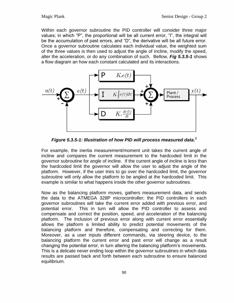
Magic Plank Senior Design - Group 2
90
Within each governor subroutine the PID controller will consider three major values; in which “P”, the proportional will be all current error, “I”, the integral will be the accumulation of past errors, and “D”, the derivative will be all future error. Once a governor subroutine calculates each individual value, the weighted sum of the three values is then used to adjust the angle of incline, modify the speed, alter the acceleration, or do any combination of such. Bellow, Fig 5.3.5-1 shows a flow diagram an how each constant calculated and its interactions.
Figure 5.3.5-1: Illustration of how PID will process measured data.1 For example, the inertia measurement/moment unit takes the current angle of incline and compares the current measurement to the hardcoded limit in the governor subroutine for angle of incline. If the current angle of incline is less than the hardcoded limit the governor will allow the user to adjust the angle of the platform. However, if the user tries to go over the hardcoded limit, the governor subroutine will only allow the platform to be angled at the hardcoded limit. This example is similar to what happens inside the other governor subroutines. Now as the balancing platform moves, gathers measurement data, and sends the data to the ATMEGA 328P microcontroller; the PID controllers in each governor subroutines will take the current error added with previous error, and potential error. This in turn will allow the PID controller to assess and compensate and correct the position, speed, and acceleration of the balancing platform. The inclusion of previous error along with current error essentially allows the platform a limited ability to predict potential movements of the balancing platform and therefore, compensating and correcting for them. Moreover, as a user inputs different commands, via steering device, to the balancing platform the current error and past error will change as a result changing the potential error, in turn altering the balancing platform’s movements. This is a delicate never ending loop within the governor subroutines in which data results are passed back and forth between each subroutine to ensure balanced equilibrium.
Magic Plank Senior Design - Group 2
91
With this balancing control scheme defined, the last piece of the puzzle is to incorporate the data sent to this module via the steering control module. Since the PID control takes care of balancing the platform, all that is needed is to specify an offset to the command that drives the motors such that it turns but is still in equilibrium. This would require that the offset be split in half and distributed equally to each wheel. For example, if the steering command is to move 50% to the left, the corresponding offset would be to move the right motor forward 25% and the left motor backward 25%. This ensures that the movement of the platform remains aligned on the center axis, thus preserving equilibrium. Now that both balancing and steering control are established, the software design is complete. The balancing platform is now capable of reading and processing raw accelerometer and gyroscope data, reading and processing raw data from the Bluetooth device and from the Nintendo Wii wireless remote controller, combining these data values into a master balancing and steering control mechanism, and outputting decisions to the motor controller.
5.4. Final Parts Selection
5.4.1. Platform Materials
The very first step in building the balancing platform was to choose a medium on which to attach, bolt, and secure all of the electronic and physical hardware. The group discussed and shared rough sketches of how the setup would be like, and after comparing ideas, it was concluded that the platform should be twenty four inches long and twelve inches wide. However, the thickness of the platform would vary on the material chosen for implementation in the final design. These minimum requirements on dimensions ensure that there will be enough space to have all the hardware secured in order for unhindered operation. First considerations included the most common materials used in everyday construction as a starting point of what material or composite to use as a platform. After some careful consideration and research it was concluded that the most common types are stainless steel, aluminum, acrylics, and polycarbonates. Each material and composite offered many advantages as well as disadvantages, and much time was spent in the consideration of the final material to be used. Stainless steel was the first consideration for a viable platform. Stainless steel offers a very rugged, stable, and durable platform to secure all the electrical and physical hardware. Unfortunately, immediate drawbacks arise from using stainless steel. It is a conductive metal, and connecting electrical hardware to this platform can pose a very possible short circuit threat. In addition, the extra time required ensuring no electrical charge build up or possible short circuits will cause unnecessary resources and man power hours. Furthermore, specialty tools will have to be used in order to perform any alterations to the stainless

Magic Plank Senior Design - Group 2
92
steel, which the tools themselves are costly. The major disadvantage of using stainless steel is a very expensive composite to use; a sheet that is 24 inches in length,12 inches wide, 0.12 inches thick, costs $61.37 making stainless steel a very cost inefficient material to use. Table 5.4.1-1 displays some physical data of Stainless Steel, as well as a recap on the cost.
Material Length Width Thickness Price
in In in $
Stainless Steel 24 12 0.120 61.37
Table 5.4.1-1: Table displaying physical data and cost of Stainless Steel.
Advantages
Rugged
Stable
Durable Disadvantages
Electrical Hardware Hazard
Requires Special Tools for Alterations
Very Expensive While wanting to continue exploring metal materials, aluminum was considered, specifically nonconductive aluminum. The nonconductive aluminum would remove the issue of potential of short circuit that stainless steel poses. Furthermore, the nonconductive aluminum is a cheaper and lighter solution than the stainless steel. As with stainless steel, the aluminum would prove to be a stable platform. Unfortunately, nonconductive aluminum is not as rugged and durable as stainless steel. In addition, aluminum cannot handle heat very well. The Sabertooth motor controller will be conducting a significant amount of heat due to an approximate 20A current flow in addition to heat from power supplies and motors. This in turn would compromise the non-conductivity of the aluminum as well as cause the aluminum to become more malleable, similarly causing internal stress within the aluminum alloy. Heat has been accounted for in the design by incorporating cooling and exhaust fans, but the risk associated with heat is still a large concern. Table 5.4.1-2 displays some physical data and cost of Nonconductive Aluminum.
Material Length Width Thickness Price
in In in $
Nonconductive Aluminum 24 12 0.125 29.35
Table 5.4.1-2: Table displaying physical data and cost of Nonconductive Aluminum.

Magic Plank Senior Design - Group 2
93
Advantages
Stable
Lightweight
Non – Conductive
Cheaper than Stainless Steel Disadvantages
Not as Rugged as Stainless Steel
Not as Durable as Stainless Steel
Heat Susceptible With metals explored, the next step is to research acrylics and polycarbonates. The first nonmetallic material to be investigated was Lexan polycarbonate; this particular polycarbonate has a high impact resistance, therefore, making Lexan polycarbonate a stable and durable material. Additionally, Lexan polycarbonate is considered a thermoplastic and can handle heat a lot better than some alloyed metals. Likewise, the amount of heat the polycarbonate can handle depends on its thickness. When heated, Lexan polycarbonate does not show signs of internal stress and crumpling observed in aluminum alloys. Standard polycarbonate sheets are 0.118 inches thick; unfortunately, because of this standard thickness, these polycarbonate sheets are not rigid. In turn, to handle the weight of all the electronic and physical hardware, thicker sheets of polycarbonate must be found or multiple sheets must be fused together to achieve desired rigidness. Both methods can prove to be time consuming; thicker sheets of polycarbonate will have to ordered and the process of fusing multiple sheets of polycarbonate can be tedious and lengthy. Table 5.4.1-3 displays some physical data and cost of Lexan Polycarbonate.
Material Length Width Thickness Price
in in In $
Lexan Polycarbonate 24 12 0.118 26.95
Table 5.4.1-3: Table displaying physical data and cost of Lexan Polycarbonate.

Magic Plank Senior Design - Group 2
94
Advantages
Lightweight
Stable
Durable
Thermoplastic Disadvantages
Not Initially Ridged
Thicker Sheets Must be Custom Ordered
Orders are Time Consuming At the same time we were investigating Lexan polycarbonate we were assessing OPTIX acrylic. Though acrylics are considered the more economic choice over polycarbonates, they share very many of the same properties of polycarbonates. In the case of OPTIX acrylic, this acrylic has a higher thermoplastic rating than Lexan polycarbonate. Additionally, this acrylic is more stable and rugged than the polycarbonate; unfortunately, because of its ruggedness it prevents the acrylic from being durable. This is because acrylic is more brittle making the acrylic more ridged than the polycarbonate; however, when enough force is applied to the acrylic is will just cause a clean snap. Consequently, this does cause complications when it comes times to attach, bolt, and secure all of the electronic and physical hardware. If care is not exercised when working with the acrylic, damage could be done to the acrylic or worse yet, irreparable damage could be done. Table 5.4.1-4 displays some physical data and cost of OPTIX Acrylic.
Material Length Width Thickness Price
in in in $
OPTIX Acrylic 24 12 0.118 22.80
Table 5.4.1-4: Table displaying physical data and cost of OPTIX Acrylic. Advantages
More cost effective than Lexan Polycarbonate
Shares many similar features and properties of Lexan Polycarbonate
Higher thermoplastic rating than Lexan Polycarbonate
More Ridged than Lexan Polycarbonate Disadvantages
OPTIX Acrylic is Brittle
Higher Risk of Breaking
Extra Care Must be Taken When Working with OPTIX Acrylic Once the investigation was completed and assessment of Lexan polycarbonate and OPTIX acrylic, the decision was not so strong on using either composite,

Magic Plank Senior Design - Group 2
95
thereby leading to the most widely used building material used today: plywood, specifically pressure treated grade A yellow pine. The first distinct major advantage of plywood is that it a very cost effective building material that can be acquired locally at any hardware store and lumberyard. The process in which pressure treated grade A yellow pine is manufactured makes it a very durable, rugged, and stable building material, that has been tested by time and nature. In addition, plywood can handle a very large weight load, which more than handles all our electrical and physical hardware needs. Moreover, pressure treated plywood can withstand very high temperatures short of a fire. Furthermore, making alterations with plywood require no special tools or requires any special care. With no immediate disadvantages in sight, the decision has been made to purchase a 24 inches long, 12 inches wide board of pressure treated grade A yellow pine plywood for the main platform. Table 5.4.1-5 displays some physical data and cost of Pressure Treated Pine Plywood.
Material Length Width Thickness Price
in in in $
Pressure Treated Pine Plywood
24 12 0.719 11.00
Table 5.4.1-5: Table displaying physical data and cost of Pressure Treated Pine Plywood.
Advantages
Most Cost Effective Building Material
Very Durable
Very Stable
Very Rugged
High Tolerance of Heat
Low Maintenance Disadvantages
None When choosing a vendor for the parts of the final implementation of this project, this dilemma was approached with a mindset of convince. Essentially, one vendor was needed who could supply all the fundamental physical hardware without having to deal with varying shipping times and cost. Time was spent talking to various people and reading online forums and discussion boards. Trough various recommendations and suggestions the vendor of choice was narrowed down to Monster Scooter Parts1; Monster Scooter Parts is a massive parts depot for various types of scooters of all purposes.

Magic Plank Senior Design - Group 2
96
When first looking, a decision had to be made on what type of scooter would provide the most cost effective parts as well as be easy to use, easy to integrate, and easy to replace. After some light research and brief discussions among the group between mobility scooters, recreational scooters, and street scooters, the general consensus was that recreation scooters would be cost effective and meet the needs of the balancing platform.
5.4.2. Motors
When first looking at motors, the initial computation was that the platform would require two twenty four Volt two hundred Watt motors. These motors would provide the proper amount of power required to maintain its own weight as well as the weight of all the electrical and physical hardware while at the same time still maintaining balanced equilibrium. When first looking at motors through Monster Scooter Parts, a twenty four Volt two hundred Watt Electric Motor with #25 Chain Sprocket (MY1016) by United Motor Co. Ltd. was found. As the name would suggest, the motor is chain driven; and to tell the truth there was no initial accounting for a motor that would drive a chain; but after a quick re-evaluation of the plans it was presently discovered that this motor would work very much so to the advantage of the system. Unfortunately, the twenty four Volt two hundred Watt Electric Motor with #25 Chain Sprocket (MY1016)2 is currently in back order with Monster Scooter Parts, and would not be available until June 08, 2012. This proves to be problematic due to the time constraint of the summer semester; therefore a suitable substitute had to be found to replace the backordered twenty four Volt two hundred Watt Electric Motor with #25 Chain Sprocket (MY1016), as seen below in Table 5.4.2-1.
Model Voltage Rated Speed Rated
Current Sprocket Power
V RPM +/- 5% A Gage W
MY 1016 by Unite Motor Co. Ltd
24 DC 2750 11 #25
Chain 200
Table 5.4.2-1: Table displaying physical data of the MY1016 motor. Keeping close to the original computed standard, the search continued for 24 Volt two hundred Watt motors. A second company by the name of Currie Technologies creates 24 Volt 200 Watt Motor with an 11 Tooth #25 Chain Sprocket, as seen in Table 5.4.2-2. The motor produced by Currie Technologies underperforms the motor by Unite Motor Co. Ltd in the rotations per minute aspect, but stays fairly the same with the rest of the attributes. This would not pose a significant problem. In fact, having a slower speed motor could prove advantages to the platform when balancing. The slower motor by Currie Technologies would actually be easier for the software speed and acceleration governors to handle. Unfortunately, the motor is also more expensive than the

Magic Plank Senior Design - Group 2
97
Unite Motor Co. Ltd motor; therefore, justifying a reason to pay more money for a motor that under performs the primary choice is impractical. Since no motor with the same power draw could be found, the search was expanded by looking for motors in the two hundred fifty Watt range. We came across another motor manufactured by Currie Technologies: the 24 Volt 250 Watt Motor with 11 Tooth #25 Chain Sprocket5, as seen in Table 5.4.2-2. Currie Technologies motor provides more power, though the increased wattage would not be a hindrance. In fact, the increase in wattage would prove to be advantageous in providing more leeway with the motors. However, compared to other motors in the same class, Currie Technologies motor still underperforms. Moreover, the price climb for the motor is much steeper than the others in its class. The cost effectiveness of Currie Technologies motors when compared to the motor attributes and power output, make choosing and implementing this particular model a last choice.
Model Voltage Rated Speed Rated
Current Sprocket Power
V RPM +/- 5% A Gage W
Currie Technologies
24 DC 2650 10.5 #25
Chain 200
Currie Technologies
24 DC 2650 - 2800 13.2 - 13.5 #25
Chain 250
Table 5.4.2-2: Table displaying physical data of Currie Technologies motor. The search continued for twenty four Volt two hundred fifty Watt motors. After looking through some different models for various scooter chassis, a motor by the same manufacture Unite Motor Co. Ltd motor was found: the 24 Volt 250 Watt Electric Motor with #25 Chain Sprocket (My1016)3. Just the Currie Technologies motor the increased wattage would prove to be advantageous in providing more room with the motors setup. As with the previous Unite Motor Co. Ltd motor all the rest of the motor attributes, including rotations per minute, proved to be superior while at the same time still maintaining cost effectiveness. Moreover, at this time the decision has been made to purchase two of the twenty four Volt two hundred fifty Watt Electric Motor with #25 Chain Sprocket (MY1016).
5.4.3. Wheels
With a motor identified from Monster Scooter Parts, the decision must now be made for wheels for the balancing platform. Since the motor drives a #25 gage chain, a wheel must be purchased that is chain driven and is of the same #25 gage chain. Since, most chain driven or belt driven wheels are part of a rear wheel assembly, there were compatible rear wheels for the 24 Volt 250 Watt Electric Motor with #25 Chain Sprocket (MY1016). Monster Scooter Parts sells a Razor rear wheel assembly that is compatible with the chain gage of the motors:

Magic Plank Senior Design - Group 2
98
the Chain Drive Rear Wheel Assembly for Razor E100, E125, E150, E175, & eSpark4, as seen in Table 5.4.3-1. Using a rear wheel assembly offers very many advantages. For one, the rear wheels will offer a wider surface than a front wheel. The wider surface will help stabilize the platform and better ensure balanced equilibrium. Furthermore, with the rear wheels being chain driven, adjustments can be made to the response of the balancing platform by either adding links to the chain to increase the slack or removing links to increase the tension.
Model Diameter Width Sprocket
Sprocket Offset Bearings Price
Mm mm Gage
and teeth mm Type # $
Razor E100, E125, E150, E175, and
eSpark
143.5 56.3 #25
Chain, 47
27 6068Z $19.99
Table 5.4.3-1: Table displaying physical data for the wheel assembly.
5.4.4. Chain
Both the motor and the rear wheel assembly require the #25 gage chain. Monster Scooter Parts sells #25 gage chain in variable length. There were a couple of different link sizes to choose from; the first link size was 52 links. 52 links is a common size, and for this link size the rear wheel assembly is located close to the motor. In the final implementation, the motor and rear wheel assemblies will be set up in a very similar manner to that of most recreational scooters. In addition, the 72 Link #25 Chain for Razor E100, E125, E150, E175, & eSpark5 is another viable #25 gage chain to use with the motor and rear wheel assembly. Though the 72 link #25 gage chain is longer, this chain can still serve its primary purpose as well as provide advantages. The longer chain can be modified to address the needs of the balancing platform. Moreover, spare chains can be created, so in a rare chance that the #25 gage chain breaks or has any other unforeseen unfortunate accident, the chain is replaceable on the fly.
5.4.5. Power Supply
During the planning phase for the final implementation of the balancing platform, it became clear that the initial decision of using a lithium or nickel metal hydride battery was insufficient for a 24 Volt motor. It was decided that using a sealed lead acid power supply solution is the better decision. While the other power supply solutions that were researched during the initial prototype design and implementation, they all posed a couple of major drawbacks. One major drawback was that those power supplies manufactured to work in portable devices. This would not in itself pose a problem, however, since the physical
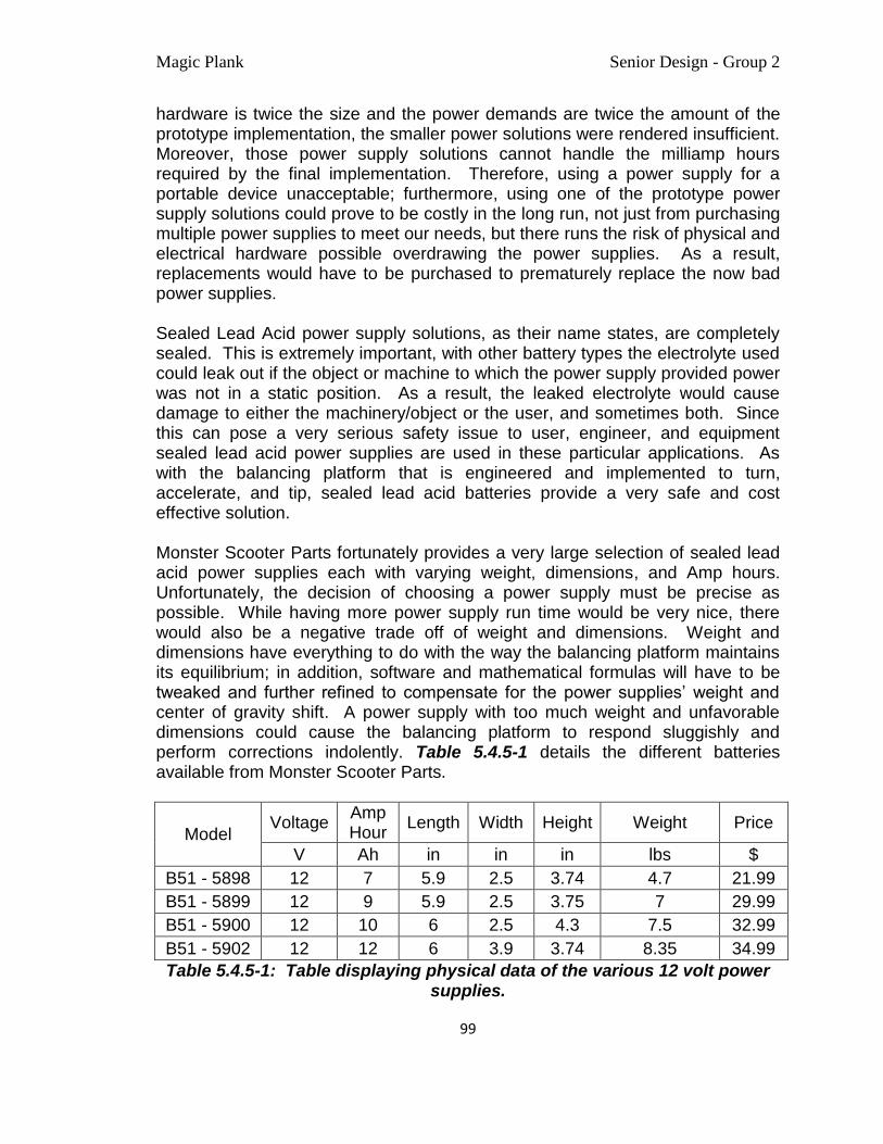
Magic Plank Senior Design - Group 2
99
hardware is twice the size and the power demands are twice the amount of the prototype implementation, the smaller power solutions were rendered insufficient. Moreover, those power supply solutions cannot handle the milliamp hours required by the final implementation. Therefore, using a power supply for a portable device unacceptable; furthermore, using one of the prototype power supply solutions could prove to be costly in the long run, not just from purchasing multiple power supplies to meet our needs, but there runs the risk of physical and electrical hardware possible overdrawing the power supplies. As a result, replacements would have to be purchased to prematurely replace the now bad power supplies. Sealed Lead Acid power supply solutions, as their name states, are completely sealed. This is extremely important, with other battery types the electrolyte used could leak out if the object or machine to which the power supply provided power was not in a static position. As a result, the leaked electrolyte would cause damage to either the machinery/object or the user, and sometimes both. Since this can pose a very serious safety issue to user, engineer, and equipment sealed lead acid power supplies are used in these particular applications. As with the balancing platform that is engineered and implemented to turn, accelerate, and tip, sealed lead acid batteries provide a very safe and cost effective solution. Monster Scooter Parts fortunately provides a very large selection of sealed lead acid power supplies each with varying weight, dimensions, and Amp hours. Unfortunately, the decision of choosing a power supply must be precise as possible. While having more power supply run time would be very nice, there would also be a negative trade off of weight and dimensions. Weight and dimensions have everything to do with the way the balancing platform maintains its equilibrium; in addition, software and mathematical formulas will have to be tweaked and further refined to compensate for the power supplies’ weight and center of gravity shift. A power supply with too much weight and unfavorable dimensions could cause the balancing platform to respond sluggishly and perform corrections indolently. Table 5.4.5-1 details the different batteries available from Monster Scooter Parts.
Model Voltage
Amp Hour
Length Width Height Weight Price
V Ah in in in lbs $
B51 - 5898 12 7 5.9 2.5 3.74 4.7 21.99
B51 - 5899 12 9 5.9 2.5 3.75 7 29.99
B51 - 5900 12 10 6 2.5 4.3 7.5 32.99
B51 - 5902 12 12 6 3.9 3.74 8.35 34.99
Table 5.4.5-1: Table displaying physical data of the various 12 volt power supplies.

Magic Plank Senior Design - Group 2
100
Calculations revealed that the electronic components would only take up a small portion of the battery life: approximately 90mA from the IMU, 100mA from the main microcontroller, and 60mA from the Bluetooth device. This power draw is well under a single ampere compared to the 250W electric motors, which are rated to draw 18-19A each. After carefully discussing the power needs of each individual electronic components, double checking calculations and reviewing all viable power supply solutions from Monster Scooter Parts, the decision was made to move on the 7 Ah 12 Volt AGM Battery (Premium)8. Based on the current draw, the platform would have roughly a half hour of battery life under high load conditions. While this is not admirable by any means, it is sufficient. This vendor brand power supply is the lightest power supply, sporting close to five pounds compared to the rest of the other power supplies currently offered. The power supplies will be placed on top of the balancing platform equidistant from each other will continue to ensure a low center of gravity. With these properties in mind, the decision has been made to purchase two of these batteries as the primary supplier of power to the balancing platform.

Magic Plank Senior Design - Group 2
101
6. Bill of Materials
6.1. Initial Design Cost Estimates
The initial cost estimate of the overall design before any significant research had been conducted is displayed below in Table 6-1. As seen when compared the final bill of materials in Table 6-3, the final implementation’s cost estimates were shifted around significantly. The motors, along with the accelerometer and gyroscope, were significantly less expensive than had been previously estimated. The estimates for the price of the power supply were also shown to be higher than what was actually required. While many of the assumed prices that were included in the initial estimate proved to be much higher than reality, the initial estimate took neither the price of the microcontroller nor the price of the printed circuit board into account. It also did not include any price for the steering mechanism. Table 6.4 summarizes the disparity between the initial and final estimates.
Item Cost (Min)
Cost (Max)
Motors $100 $500
Motor Controllers $20 $200
Power Supply $80 $250
Gyroscope & Accelerometer $60 $350
Mechanical Structure $0 $100
Software $0 $0
Total $260 $1,400
Average Cost $830
Table 6-1: Price projections for Magic Plank.

Magic Plank Senior Design - Group 2
102
6.2. Prototype Bill of Materials
The following table, Table 6-2, details the parts purchased for the prototype. All of the listed parts and tools have since been acquired.
Item Source # Price Tax/S&
H Total
IMU Fusion Board - ADXL345 & IMU3000 Sparkfun 1 $59.95 $3.64 $63.59
Arduino Uno R3 Sparkfun 1 $29.95 $3.34 $33.59
Bluetooth Mate Silver Sparkfun 1 $39.95 $17.14 $57.09
Logic Level Converter Sparkfun 1 $1.95 $3.64 $5.59
Bluetooth SMD Module RN - 42 Sparkfun $15.95 $3.64 $19.95
Sabertooth 2X12 dual 12A Motor Driver
Dimension Engineering 1 $79.99 $2.50 $82.49
5V 1A switching Voltage Regulator
Dimension Engineering 1 $15.00 $1.25 $16.25
13700RPM 6-12VDC Motor Skycraft 3 $5.95 $1.25 $21.60
Desolder pump Skycraft 1 $5.50 $0.36 $5.86
Solder Wick Skycraft 2 $1.95 $0.25 $4.15
14.4V 24mAh Li-Ion Battery Skycraft 3 $19.95 $4.19 $72.42
2.5" Wheel Skycraft 2 $0.75 $0.11 $1.71
N-7000 Transistor Skycraft 8 $0.25 $0.14 $3.12
Wire Strippers Skycraft 1 $7.95 $0.52 $8.47
Bernzomatic Butane The Home Depot 2 $3.97 $0.52 $8.46
Betnzomatic Butane Flame Torch and
Accessory Kit The Home Depot 1 $15.97 $1.12 $17.09
Bernzomatic 4 oz. Leaded Solid Wire Solder
The Home Depot 1 $9.97 $0.65 $10.62
CAT IV 600V Auto - Range Digital Multimeter
The Home Depot 1 $62.95 $4.09 $67.04
Duracell 9V 2 - Pack The Home Depot 1 $7.47 $0.49 $7.96
Total $507.04
Table 6-2: Table displaying cost of prototyping materials and supplies.

Magic Plank Senior Design - Group 2
103
6.3. Final Design Bill of Materials
Table 6-3, displayed below, details the bill of materials for the final design. These parts, while all essential to the design of the project, have not all yet been acquired and include some price estimates as a result.
Item Source Q Price Total
ADXL345 accelerometer Sparkfun 1 $14.95 $14.95
IMU-3000 gyroscope Component
Distributors Inc 1 $12.00 $12.00
Bluetooth RN-42 Sparkfun 1 $15.95 $15.95
Nintendo Wii wireless remote controller - 1 - $0.00
ATmega328P-PU Newark 1 $2.24 $2.24
ATmega16U2 Digi-Key 1 $3.82 $3.82
Sabertooth 2x25 Motor Controller
Dimension Engineering 1 $125.00 $125.00
B51-5898 Sealed Lead Acid Battery 12V
Monster Scooter Parts 2 $21.99 $43.98
Razor E100 Sprocketed Wheels
Monster Scooter Parts 2 $19.99 $39.98
Currie Technologies 24V DC Sprocketed Motor 250W
Monster Scooter Parts 2 $36.95 $73.90
#25 Roller Chain - 10' Amazon 1 $28.00 $28.00
Pressure Treated Plywood Lowes 1 $15.00 $15.00
Miscellaneous Circuit Parts - 1 $20.00 $20.00
Miscellaneous Platform Parts - 1 $20.00 $20.00
PCB Cost Estimate - 1 $40.00 $40.00
Subtotal $454.82
Shipping / Tax Estimates $50.00
Estimated Total $504.82
Table 6-3: Table displaying projected cost of final implementation materials and supplies.
To summarize the disparity between what the predicted financial requirements for the project were and what it is now seen to be, Table 6-4, shown below, displays a comparison between the initial cost estimate and the cost actual implementation. The total money spent was higher than the average initial estimate, but the cost for final implementation is shown to be significantly less.

Magic Plank Senior Design - Group 2
104
Prototype Cost
Final Implementation Estimate
Total Final Estimate
Initial Cost Estimate (Avg)
$507.04 $504.82
$1011.86 $830
Table 6-4: Table summarizing all projected costs.

Magic Plank Senior Design - Group 2
105
Works Cited
3. Initial Research
3.2. Robotics Club
1. LPY503AL Dual 30°/s Gyro Breakout Board. http://www.sparkfun.com/products/9424
2. LPY5150AL 1500°/s Dual Axis Gyro. http://www.sparkfun.com/products/9445
3. MMA7361L Triple Axis Accelerometer. http://www.sparkfun.com/products/854
4. MMA7361 Triple Axis Accelerometer Breakout http://www.sparkfun.com/products/9652
5.IMU Digital Combo Board IMU3000/ADXL345 http://www.sparkfun.com/products/10252
6. RoboteQ SDC2150 2x20A (50V) motor controller.
http://www.roboteq.com/brushed-dc-motor-controllers/sdc2130-sdc2150-dual-20a-
brushed-dc-motor-controller
7. Sabertooth 2X25, 2X12, 2X5 motor drivers. http://dimensionengineering.com/
8. Thunder Power RC http://www.thunderpowerrc.com/
9.G6 Pro Performance 45C Series Batteries.
http://www.thunderpowerrc.com/G6ProPerformance45CSeriesLiPoBatteries.htm
3.3. Initial Research of Coding Implementation
1. Texas Instruments Stellaris LM3S8962 http://www.ti.com/product/lm3s8962
2. Sourcery CodeBench - http://www.mentor.com/embedded-software/sourcery-
tools/sourcery-codebench/overview/
3. Arduino Uno - http://arduino.cc/en/Main/ArduinoBoardUno
3.4. Power Supply
1. http://www.hardwaresecrets.com/article/The-Truth-About-NiCd-Batteries/292/1
2. http://www.servocity.com/html/nicad_vs__nimh_batteries.html 3. http://www.greenbatteries.com/bachfa.html 4. http://batteryuniversity.com/learn/article/is_lithium_ion_the_ideal_battery

Magic Plank Senior Design - Group 2
106
5. http://electronics.howstuffworks.com/everyday-tech/lithium-ion-battery.htm 6. http://www.batteryeducation.com/2006/04/what_is_the_dif.html
7. http://www.thunderpowerrc.com/ 8. http://www.dimensionengineering.com/ 9. http://www.dimensionengineering.com/Sabertooth2X12.htm 10. http://www.lynxmotion.com/default.aspx 11. http://www.lynxmotion.com/p-727-120-volt-ni-mh-2800mah-battery-pack.aspx 12. http://batteryuniversity.com/learn/article/whats_the_best_battery
13. http://www.skycraftsurplus.com/index.aspx
3.5. Steering Implementation
1. Scooter Picture - http://www.worx-scooters.com/stunt-scooter-pro/
3.6 Switching Voltage Regulator
1. http://www.ti.com/lsds/ti/microcontroller/arm_stellaris/overview.page
2. http://www.dimensionengineering.com/Sabertooth2X12.htm
3. http://www.sparkfun.com/products/10252
4. http://www.digikey.com/us/en/info/Company-Profile.htm
5. http://search.digikey.com/scripts/DkSearch/dksus.dll?WT.z_header=search_go&lang=en
&site=us&keywords=LM7805CT-ND&x=13&y=14
6. http://www.dimensionengineering.com/de-sw050.htm
7. http://www.dimensionengineering.com/switchingregulators.htm
4. Prototype
4.1. Macroscopic Design
4.2. Hardware Selection

Magic Plank Senior Design - Group 2
107
4.2.1. IMU (Inertial Measurement Unit)
1. IMU-3000 Triple Axis Gyroscope: http://www.invensense.com/mems/gyro/imu3000.html
2. ADXL345 Triple Axis Accelerometer: http://www.sparkfun.com/products/9045
3. BMA180 Triple Axis Accelerometer: http://www.sparkfun.com/products/9630
4.2.2. Motor Controller
1. Sabertooth 2X12 Motor Driver: http://dimensionengineering.com/Sabertooth2X12.htm
4.2.2. Microcontroller
1. LM3S8962 Datasheet V.G, p. 659
2. LM3S8962 Datasheet V.G, p. 514
3. LM3S8962 Datasheet RevG, p. 434
4. StellarisWare Workshop workbook, p. 1-13
5. Arduino - http://www.arduino.cc/
6. ATmega2560 Datasheet, p. 5
7. ATmega328 Datasheet, p. 5
8. Arduino Uno - http://arduino.cc/en/Main/ArduinoBoardUno
4.3. Hardware Implementation
4.3.1. Remote Control
1. SMD Module – RN – 42 – http://www.sparkfun.com/products/10253
2. Android ES File Explorer – http://www.estrongs.com/products/es-file-explorer.html
3. Amarino Toolkit – http://www.amarino-toolkit.net/
4. PlayStation 3 and Wii Game Controllers on the Arduino –http://www.circuitsathome.com/mcu/ps3-and-wiimote-game-controllers-on-the-arduino-
host-shield-part-3/
5. BlueZ Bluetooth Protocol Stack – http://www.bluez.org/
6. SMD Module – RN – 42 Design Details –http://beaversource.oregonstate.edu/projects/44x201125/wiki/WirelessCommunication

Magic Plank Senior Design - Group 2
108
4.4. Software Prototyping
4.4.1. Using Bluetooth With a Wiimote
1. Arduino Coding Tutorial – http://www.arduino.cc/ 2. Nintendo Wii Game Controller Button Layout – http://homepage.mac.com/ianrickard/wiimote/wiili_wimote.html 3. Nintendo Wii Game Controller Button Layout Configuration – http://wiibrew.org/wiki/Wiimote
5. Final Implementation
5.1. Hardware Design
5.1.1. Circuit Design
1. Arduino Uno R3 - http://arduino.cc/en/Main/ArduinoBoardUno
2. IMU Fusion Board – ADXL345 & IMU3000 - http://www.sparkfun.com/products/10252
3. Bluetooth Mate Silver - http://www.sparkfun.com/products/10393
5.1.2. Motor Controller
1. Sabertooth 2x25 guide, used with permission -http://www.dimensionengineering.com/
5.3. Software Design
5.3.1. Motor Controller: Sabertooth 2x25
1. Arduino Code references: http://arduino.cc/en/Reference/Libraries
2. Sabertooth 2x25 guide - http://www.dimensionengineering.com/products/sabertooth2x25
3. Packetized Serial guide - http://psurobotics.org/wiki/index.php?title=SyRen_10
5.3.2. IMU – Raw Data Reading
1. Arduino Code references - http://arduino.cc/en/Reference/Libraries
2. ADXL345 Datasheet - Register Map, p. 14.
3. IMU-3000 Datasheet – Register Map, p. 29.

Magic Plank Senior Design - Group 2
109
4. Code reference for interfacing - www.hobbytronics.co.uk/arduino-adxl345-
imu3000
5.3.3. IMU – Processing Raw Data
1. Using a Kalman Filter with Arduino - http://arduino.cc/forum/index.php/topic,58048.0.html
2. Kalman vs Complimentary - http://robottini.altervista.org/tag/complementary-filter
3. Kalman Filtering – http://www.x-firm.com/?page_id=145
4. Kalman Filtering - http://tom.pycke.be/mav/71/kalman-filtering-of-imu-data
5. Higgins, Walter T. – A Comparison of Complementary and Kalman Filtering
5.3.5. Top Level – PID Control
1. PID loop - http://en.wikipedia.org/wiki/File:PID_en.svg
5.4. Final Parts Selection
1. http://www.monsterscooterparts.com/ 2. http://www.monsterscooterparts.com/24vo200wamow.html 3. http://www.monsterscooterparts.com/24v250wmotor.html 4. http://www.monsterscooterparts.com/24-volt-200-watt-motor-currie.html 5. http://www.monsterscooterparts.com/24-volt-250-watt-motor-currie.html
6. http://www.monsterscooterparts.com/rae1rewhasch.html 7. http://www.monsterscooterparts.com/rae1ch72li25.html
8. http://www.monsterscooterparts.com/12vo7amphoba.html