Application of Cellulose and Cellulose Derivatives in Pharmaceutical Industries

ORIGINAL PAPER
Self-assembled optically transparent cellulose nanofibrilfilms: effect of nanofibril morphology and drying procedure
Yan Qing • Ronald Sabo • Yiqiang Wu •
J. Y. Zhu • Zhiyong Cai
Received: 23 September 2014 / Accepted: 26 January 2015 / Published online: 4 February 2015
� Springer Science+Business Media Dordrecht (outside the USA) 2015
Abstract Cellulose nanofibril (CNF) films currently
provide great opportunity in many applications with
advantages of excellent mechanical strength, high
light transmittance, and good barrier properties.
However, processes for preparing CNFs are typically
tedious and vary, along with their properties. Here,
five preparation methods using various combinations
of filtration, freeze-drying, and casting are applied to
produce CNF films, and their major properties are
compared. Three different types of CNFs having a
range of fiber diameter and aspect ratio were examined
using each of these five preparation methods. Because
of limited hydrogen bonds and nanofibril arrangement,
the freeze-dried CNF films displayed reduced mechan-
ical strength and light transmittance compared to the
other methods, although freeze-drying was relatively
fast. Some effects of film production methods on
measured crystallinity were also observed with freeze-
dried samples having lower crystallinity than films
similarly produced by filtration and drying. Free-
standing CNF films produced by casting at room
temperature required long times and mold growth was
sometimes observed, but cast films made from 2,2,6,6-
tetramethylpiperidine-1-oxyl radical-oxidized CNFs
had the highest light transmittance of any samples.
Filtration of CNF suspensions followed by air- or
oven-drying produced films with minimal defects,
high mechanical strength, and good light transmit-
tance with relatively little effort. Therefore, this
filtration procedure is recommended for producing
CNF films.
Keywords Cellulose nanofibrils � Self-assembled
films � Filtration � Freeze-drying � Casting �Mechanical and optical properties
Introduction
Because it has become increasingly desirable to
develop materials from sustainable resources, ligno-
cellulosics and cellulose nanomaterials in particular
have recently received a great deal of attention for their
potential to replace materials created from nonsustain-
able resources. Among the promising characteristics of
cellulosic nanomaterials is their high strength, with the
crystalline region of cellulose having an elastic mod-
ulus of about 150 GPa (Cheng and Wang 2008;
Iwamoto et al. 2009). Cellulose nanofibrils (CNFs),
Y. Qing � Y. Wu
School of Materials Science and Engineering,
Central South University of Forestry and Technology,
498 Shaoshan South Road, Changsha 410004, China
Y. Qing � R. Sabo (&) � J. Y. Zhu � Z. Cai (&)
Forest Products Laboratory, United States Department of
Agriculture, 1 Gifford Pinchot Drive, Madison,
WI 53726-2398, USA
e-mail: [email protected]
Z. Cai
e-mail: [email protected]
123
Cellulose (2015) 22:1091–1102
DOI 10.1007/s10570-015-0563-9

one type of cellulose nanomaterial, were first reported
in the early 1980s (Herrick et al. 1983; Turbak et al.
1983). CNFs are typically isolated using high-intensity
mechanical fibrillation of coarse lignocellulosic fibers
typically in combination with chemical or enzymatic
pretreatment (Paakko et al. 2007; Saito et al. 2009;
Qing et al. 2013b). CNFs are typically entangled
networks of nanoscale cellulose fibrils, having high
aspect ratio and a large specific surface area, and they
have been shown to have interesting and useful
properties. For example, CNF nanofibrils uniformly
dispersed in the aqueous suspension present as stable
gels even at solids concentrations as low as 0.3 %
(Paakko et al. 2007), and films formed from CNFs have
been reported as having low coefficients of thermal
expansion, good mechanical strength, and high trans-
parency. Therefore, many attempts have been devoted
to develop green and high-quality CNF products with
applications including barrier and transparent films,
engineering polymeric composites, and functional
aerogels (Capadona et al. 2007; Okahisa et al. 2009;
Aulin et al. 2010; Olsson et al. 2010).
Films made from CNFs are of particular interest
because of their properties and because of their analogy
to papermaking in which the fiber suspensions can be
dewatered and formed into sheets. When removing the
water (or other solvent) from a CNF suspension, the
adjacent individual nanofibrils initially collapse by the
capillary force and later form strong hydrogen bonds
between hydroxyl groups, which are abundant on the
fiber surface (Nystrom et al. 2010). The obtained films
are dense, stiff, and transparent and exhibit layered and
possibly even porous structures, depending on the
properties of the raw nanofibrils and the dewatering
process. The tensile strength and elastic modulus for
the films reported in the literature ranged from
100–230 MPa to 8–15 GPa, respectively, and varied
depending on fiber resources and processing condi-
tions. Notably, orientated 2,2,6,6-tetramethylpiperi-
dine-1-oxyl radical- (TEMPO-)oxidized CNF films
with the degree of fiber orientation more than 80 %
showed tensile strength and modulus as high as
400 MPa and 33 GPa, respectively (Sehaqui et al.
2012). Because of extremely small diameters (usually
much less than 100 nm) of CNFs, the scattering and
absorption of visible light by the nanofibrils is limited,
which leads to highly transparent CNF films. A 20-lm-
thick TEMPO-oxidized CNF film prepared with fiber
diameters of 3–4 nm is reported to achieve 90 %
transmittance at the wavelength of 600 nm (Fukuzumi
et al. 2009). Nanofibrils are randomly deposited into
layered structures with small pores that are not
interconnected, resulting in films with porosities on
the order of 10 %. Thus, low molecular weight
substances like oxygen, carbon oxidation, and oil are
limited to permeate through the networked films
(Fukuzumi et al. 2009; Aulin et al. 2010; Qing et al.
2013a, b). The good barrier performance makes it
possible to be regarded as a potential substitution for
conventional fossil-derived plastic products in pack-
age and carrier. Since then, the widely demonstrated
applications for CNF films range from coating, pack-
age, medical carrier, to loudspeaker membranes,
transparent LED substrate, battery electrodes, and
flexible electronics (Henriksson and Berglund 2007;
Okahisa et al. 2009; Aulin et al. 2010; Nystrom et al.
2010; Sabo et al. 2012).
Two predominant approaches are reported in the
literature for preparing CNF films. One popular
method is solution casting, by which nanofibril
suspensions are kept in open containers, and the
solvent, usually water, is allowed to gradually evap-
orate (Aulin et al. 2010). Casting is a time-consuming
process, typically taking days or weeks. For example,
Sehaqui et al. (2010) reported that preparing 40-lm-
thick films with a diameter of 80 mm under atmo-
spheric conditions starting with CNF concentration of
0.2 wt% took more than 120 h. To accelerate the
processing, the castings are sometimes carried out with
slight heating under vacuum (Spence et al. 2010;
Xhanari et al. 2011; Rodionova et al. 2012). A second
popular and relatively fast method to produce CNF
films involves the filtration of CNF solutions and
drying the obtained hydrogels (Henriksson et al. 2008;
Qing et al. 2013b). In this method, which is similar to a
paper-making process, CNF suspensions are filtered
under vacuum or pressure using membranes with pores
typically hundreds of nanometers in diameter (Fukuz-
umi et al. 2009; Sehaqui et al. 2010; Qing et al. 2013b).
Various methods have been used to dry the resulting
hydrogels including air-drying (Qing et al. 2013b),
oven drying (Henriksson et al. 2008; Fukuzumi et al.
2009), and hot-pressing (Nakagaito and Yano 2005).
Sehaqui et al. (2010) even reported a processing
technique in which a CNF gel ‘‘cake’’ was vacuum- and
hot-dried in a special apparatus resulting in a drying
time of about 1 h. Freeze-drying, which allows aque-
ous solvents in the suspension to directly sublimate
1092 Cellulose (2015) 22:1091–1102
123

from a solid to gas phase of dilute CNF suspensions, is
a popular method to prepare CNF aerogels having high
porosity (Paakko et al. 2008; Svagan et al. 2010). In the
current work, freeze-drying is explored as an alterna-
tive route for drying the wet CNF hydrogels. Freeze-
drying reduces the collapse between neighboring
nanofibrils and largely limits shrinkage, especially
wrinkling at the edge of CNF films. The properties of
films from these different methods vary significantly,
although the contribution of the processing conditions
on these property variations is not clear.
Variations in microstructure of CNFs and their films
are known to significantly impact the performance of the
films. For example, Henriksson et al. (2008) reported
that mechanical strength of CNF films was strongly
dependent on the degree of polymerization (DP) of raw
nanofibrils and on the porosity of films. Similarly,
Retegi et al. (2010) prepared bacterial cellulose (another
kind of cellulose nanofiber) films with controlled
density by varying compression pressures. They found
that the tensile modulus was linearly enhanced with
increasing mold pressure, which also led to slight
increases in tensile strength. CNF film preparation
procedures affect the films’ shrinkage, appearance,
strength, vapor permeability, and opacity (Dalmas et al.
2007; Retegi et al. 2010; Sehaqui et al. 2010). However,
the effect of preparation methods on the final properties
of CNF films has not been studied in detail.
Therefore, in the current work we prepared CNF
films using various processing conditions, namely
casting and filtration followed by either air- or freeze-
drying. In addition, the effect of hot-pressing on the
properties of CNF films was examined to produce flat,
wrinkle-free films. Three kinds of cellulose nanofibrils
having different morphologies were used to create films
using multiple processing techniques to further eluci-
date the roles of raw materials and processing on the
physical and mechanical properties of the films. The
appearance, morphology, porosity, mechanical proper-
ties, and visible light transmittance of the obtained films
were characterized and are reported here.
Materials and methods
Preparation of CNFs
Three kinds of cellulose nanofibrils were used in this
study to prepare CNF films; they are TEMPO-oxidized
nanofibrils, nanofibrils refined with multiple enzyme
pretreatments (MER) and the MER nanofibrils fol-
lowed by microfluidization (MERM). The starting
cellulose fibers were fully bleached kraft eucalyptus.
Detailed descriptions of the preparation procedures
were previously reported by Qing et al. (2013a, b) and
are briefly described here. TEMPO-oxidized CNFs
were produced according to the method reported by
Saito et al. (2009). Enzyme-treated CNFs (MER and
MERM) were prepared by pretreating the pulp fiber
suspensions at a solid consistency of 1.5 % with
commercial enzymes with trade names FiberCare�
Cellulclast 1.5 L from Novozymes (Franklinton, NC,
USA). The enzyme pretreated fibers were then
mechanically refined for 6 h using a MKZA6-2
SuperMass-Colloider (Masuko Sangyo Co., Ltd., Sai-
tama, Japan) at 15,000 rmp with a disk gap of -5 lm,
and these samples were labeled as MER. A portion of
the obtained MER nanofibrils were subjected to further
intense fibrillation in a M-110EH-30 Microfluidizer
(Microfluidics, Newton, MA, USA). The fiber suspen-
sion was diluted to 1 % solids and passed through an
87-lm chamber 15 times at pressure of 138 MPa, and
these samples were labeled as MERM.
Preparation of CNF films
CNF films were prepared by either solution casting or
by filtering CNF suspensions followed by air-, oven-
or freeze-drying the wet hydrogel films. In some cases,
the films were also hot-pressed. Altogether, five
different processing methods were examined, and
these processing methods are illustrated in Fig. 1.
Four of the five methods involved first filtering CNF
suspensions to obtain a hydrogel film, which could then
be further dried using various conditions. The filtration
procedure was performed by first diluting the CNF
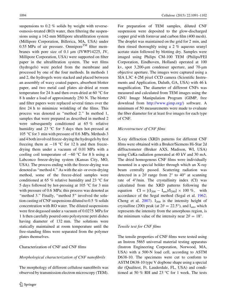
Fig. 1 Various processing methods for preparation of self-
assembled CNF films
Cellulose (2015) 22:1091–1102 1093
123
suspensions to 0.2 % solids by weight with reverse-
osmosis-treated (RO) water, then filtering the suspen-
sions using a 142-mm Millipore ultrafiltration system
(Millipore Corporation, Billerica, MA, USA) under
0.55 MPa of air pressure. OmniporeTM filter mem-
branes with pore size of 0.1 lm (JVWP14225, JV,
Millipore Corporation, USA) were supported on filter
paper in the ultrafiltration system. The wet films
(hydrogels) were peeled from the membrane and
processed by one of the four methods. In methods 1
and 2, the hydrogels were stacked and placed between
an assembly of waxy coated papers, absorbent blotter
paper, and two metal caul plates air-dried at room
temperature for 24 h and then oven-dried at 60 �C for
8 h under a load of approximately 250 N. The blotter
and filter papers were replaced several times over the
first 24 h to minimize wrinkling of the films. This
process was denoted as ‘‘method 2.’’ In method 1,
samples that were prepared as described in method 2
were subsequently conditioned at 65 % relative
humidity and 23 �C for 5 days then hot-pressed at
105 �C for 3 min with pressure of 0.6 MPa. Methods 3
and 4 both involved freeze-drying the hydrogels by first
freezing them at -18 �C for 12 h and then freeze-
drying them under a vacuum of 0.01 MPa with a
cooling coil temperature of -60 �C for 8 h using a
Labconco freeze-drying system (Kansas City, MO,
USA). The process ending with the freeze-drying was
denoted as ‘‘method 4.’’ As with the air- or oven-drying
method, some of the freeze-dried samples were
conditioned at 65 % relative humidity and 23 �C for
5 days followed by hot-pressing at 105 �C for 3 min
with pressure of 0.6 MPa; this process was denoted as
‘‘method 3.’’ Finally, ‘‘method 5’’ involved the solu-
tion casting of CNF suspensions diluted to 0.5 % solids
concentration with RO water. The diluted suspensions
were first degassed under a vacuum of 0.0275 MPa for
1 h then carefully poured onto polystyrene petri dishes
having diameter of 132 mm. The solutions were
statically maintained at room temperature until the
free-standing films were separated from the polymer
plates themselves.
Characterization of CNF and CNF films
Morphological characterization of CNF nanofibrils
The morphology of different cellulose nanofibrils was
observed by transmission electron microscopy (TEM).
For preparation of TEM samples, diluted CNF
suspension were deposited to the glow-discharged
copper grid with formvar and carbon film (400 mesh).
The droplet was maintained on the grid for 2 min, and
then rinsed thoroughly using a 2 % aqueous uranyl
acetate stain followed by blotting dry. Samples were
imaged using Philips CM-100 TEM (Philips/FEI
Corporation, Eindhoven, Holland) operated at 100
kv, spot 3,200-lm condenser aperture, and 70-lm
objective aperture. The images were captured using a
SIA L3C 4-2M pixel CCD camera (Scientific Instru-
ments and Application, Duluth, GA, USA) with 46 k
magnification. The diameter of different CNFs was
measured and calculated from TEM images using the
GNU Image Manipulation Program (GIMP, free
download from http://www.gimp.org/) software. A
minimum of 50 measurements were made to evaluate
the fiber diameter for at least five images for each type
of CNF.
Microstructure of CNF films
X-ray diffraction (XRD) patterns for different CNF
films were obtained with a Bruker/Siemens Hi-Star 2d
diffractometer (Bruker AXS, Madison, WI, USA)
using CuKa radiation generated at 40 kV and 30 mA.
The dried homogenous CNF films were individually
mounted in a special holder through which an X-ray
beam centrally passed. Scattering radiation was
detected in a 2h range from 2� to 40� at scanning
rate of 4�/min. The crystallinity index (CI) was
calculated from the XRD patterns following the
equation CI = [(I200 - Iam)/I200] 9 100 %, with
accordance of the Segal method (Segal et al. 1962;
Cheng et al. 2007). I200 is the intensity height of
crystalline (200) peak (at 2h = 22.5�), and Iam, which
represents the intensity from the amorphous region, is
the minimum value of the intensity near 2h = 18�.
Tensile test for CNF films
The tensile properties of CNF films were tested using
an Instron 5865 universal material testing apparatus
(Instron Engineering Corporation, Norwood, MA,
USA) with a 500-N load cell, according to ASTM
D638-10. The specimens were cut to conform to
ASTM D638-10 type V dogbone shape using a special
die (Qualitest, Ft. Lauderdale, FL, USA) and condi-
tioned at 50 % RH and 23 �C for 1 week. The tests
1094 Cellulose (2015) 22:1091–1102
123

were conducted at a cross-head speed of 1 mm/min in
a room conditioned at 50 % RH and 23 �C, and a pre-
load of 5 N was applied to remove slack. At least six
specimens were tested for each condition. An LX 500
laser extensometer (MTS Systems Corporation, Eden
Prairie, MN, USA) was used to determine the
displacement with sampling frequency of 10 Hz.
The laser recorded the displacement between two
strips of reflective tape initially placed approximately
8 mm apart on the necked-down region of the dog-
bone specimens. Strain was calculated from the
determined extension and initial gauge length. Film
density was calculated gravimetrically by measuring
the dimension and weight of well-defined sections of
each film. The corresponding porosity was estimated
by the following equation:
Porosity ¼ 1� qfil
qcel
� �� 100 %
Here qfil and qcell are the densities of the obtained CNF
film and neat cellulose (1,500 kg/m3), respectively.
UV–Vis light transmittance
The visible light transmittance for CNF films was
measured at a wavelength range from 400 to 800 nm
using an U-4100 ultraviolet–visible (UV–Vis) spec-
trometer (Hitachi High Technologies America Inc.,
Schaumburg, IL, USA). Rectangular specimens with
size of 40 mm 9 9 mm (length 9 width) were placed
in a quartz cuvette and measured by placing it 25 cm
away from the entrance port of the integrating sphere.
The specimens were conditioned at 50 % RH and
23 �C for 2 days prior to testing, and two tests were
performed for each sample.
Results and discussion
Morphological characteristic of nanofibrils
Transmission electron micrographs of the CNFs
(Fig. 2) reveal that all the nanofibrils are of fine
widths less than 100 nm. The diameters of the CNFs
were evaluated from the TEM images, and their
distributions are shown in Fig. 2. The network struc-
ture of the interconnected nanofibrils makes it
extremely difficult to detect the length of individual
fibrils from the images, so these are not reported here.
For the most part, the three types of CNFs are
networked, although MERM CNFs appear to be less
networked and contain some discreet rod-shaped
particles. The TEMPO-oxidized CNFs have uniform
diameters in the range of 3–8 nm, are highly net-
worked, and have high aspect ratios (fiber length/
diameter). The chemical oxidation reaction to produce
Fig. 2 TEM images (up) and size distributions (below) of different CNFs. a MER; b MERM; and c TEMPO. The scale bars are
100 nm
Cellulose (2015) 22:1091–1102 1095
123

these fibers creates repulsive forces that contribute to
the separation of individual microfibrils (Saito et al.
2009). This chemo-mechanical fibrillation also pri-
marily conserves the original cellulose structure
further resulting in good physical and mechanical
properties (Siro and Plackett 2010). The enzymatically
and mechanically treated MER and MERM CNFs
appear wider and shorter than the TEMPO CNFs. The
MER CNFs have a significant number of fiber bundles
with diameters ranging from about 15 to 85 nm.
Further refining in a Microfluidizer resulted in
decreased diameters (5–30 nm) and a reduction in
the number of fibril aggregates. Similar results were
shown in our previous work (Qing et al. 2013a, b), in
which extensive enzymatic and mechanical treatments
resulted in CNFs containing predominantly discreet
rod-shaped particles. However, in the current work,
MERM appears somewhat more networked than the
fibers undergoing treatment similar to that in the
previous report. Nonetheless, the Microfluidizer clear
results in CNFs with reduced diameters and breaks
apart some of the network structure.
Film appearance and preparation time
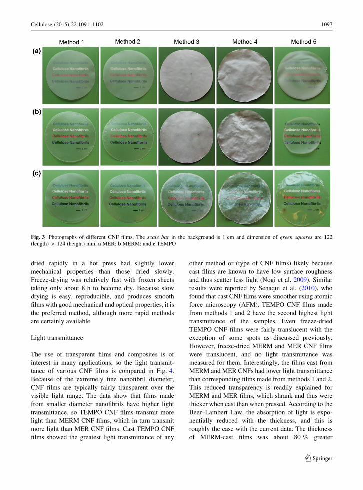
Photographs of CNF films prepared by the different
processing conditions are shown in Fig. 3. The freeze-
dried films are clearly more opaque than the cast or
pressed films. The freeze-dried films created from
enzymatic and mechanical treatments are completely
opaque and appear white, whereas the freeze-dried
TEMPO CNF films are translucent with some spots
more opaque than others. Freeze-drying reduces the
capillary forces responsible for collapsing fibers, thus
preventing them from hydrogen bonding as they
would when cast or dried under pressure (Paakko
et al. 2008; Peng et al. 2012). Therefore, microgaps
generated among interconnected nanofibrils signifi-
cantly increase the light scattering because of the
difference in refractive index between the nanofibrils
(1.54) and air (1.0) (Mark 2007). This limitation of
capillary force collapse during freeze-drying subse-
quently conserves the initial state of loose nanofibrils.
Okamoto and Meshisuka (2010) showed that wood
pulp fiber dried by freeze-drying (or supercritical
drying) were more swollen than when dried by
conventional air-drying.
Significant moisture gradients are created between
the surface and core of the films during drying,
especially in the freeze-drying and casting process.
This moisture gradient creates residual stresses, which
result in deformation of the films, which can be clearly
seen as rough films for methods 4 and 5 in Fig. 3.
Further conditioning, which allows for moisture
absorption and subsequent hot-pressing, resulted in
much smoother surfaces for the freeze-dried films (as
shown for method 3 in Fig. 3). On the other hand, the
constrained drying between absorbent papers (method
2) resulted in smooth surfaces without further condi-
tioning and hot-pressing. Interestingly, the cast
MERM CNF films shrank significantly compared to
all other types of CNFs and process conditions. This
happened for each of the three replicates, and the
phenomena is not readily understood. During the
casting process, the center of the drying films was
observed to become solid-like before the outer
regions. Perhaps the smaller, more discreet CNFs in
the MERM samples were more likely to move and
displace water than the more networked CNFs in the
other samples. However, further investigation of this
phenomenon is warranted as it may have implications
in processing and properties of materials containing
these types of CNFs. Another observation worthy of
note is that cast CNF films sometimes developed mold
growth. Overall, films prepared by methods 1 and 2
appear to have the most consistent and desirable
appearance.
Efficient preparation of CNF films is one concern-
ing issue for industrial scalability as dewatering and
drying require a great deal of time and energy. The
preparation times for producing CNF films in this
study varied from about 30 h to more than 2 weeks.
Solution casting took the longest amount of time with
films of about 100-lm thicknesses taking at least
2 weeks to dry under ambient conditions. The filtra-
tion process for TEMPO CNFs was slower than for the
enzymatically treated CNFs, but all samples reported
here were left in the filtration apparatus for 10 h. The
process could be sped up dramatically by using
filtration membranes with larger pores in a method
similar to that reported by Sehaqui et al. (2010), in
which pore sizes of about 650 nm were used instead of
the 100-nm pore sizes used in this study. Rapid drying
of the films is possible, such as in a hot press at
elevated temperatures. However, rapid drying often
results in deformation or blow-out of the sheet
resulting in holes or sheets with undesirable appear-
ance. Sehaqui et al. (2010) also reported that films
1096 Cellulose (2015) 22:1091–1102
123
dried rapidly in a hot press had slightly lower
mechanical properties than those dried slowly.
Freeze-drying was relatively fast with frozen sheets
taking only about 8 h to become dry. Because slow
drying is easy, reproducible, and produces smooth
films with good mechanical and optical properties, it is
the preferred method, although more rapid methods
are certainly available.
Light transmittance
The use of transparent films and composites is of
interest in many applications, so the light transmit-
tance of various CNF films is compared in Fig. 4.
Because of the extremely fine nanofibril diameter,
CNF films are typically fairly transparent over the
visible light range. The data show that films made
from smaller diameter nanofibrils have higher light
transmittance, so TEMPO CNF films transmit more
light than MERM CNF films, which in turn transmit
more light than MER CNF films. Cast TEMPO CNF
films showed the greatest light transmittance of any
other method or (type of CNF films) likely because
cast films are known to have low surface roughness
and thus scatter less light (Nogi et al. 2009). Similar
results were reported by Sehaqui et al. (2010), who
found that cast CNF films were smoother using atomic
force microscopy (AFM). TEMPO CNF films made
from methods 1 and 2 have the second highest light
transmittance of the samples. Even freeze-dried
TEMPO CNF films were fairly translucent with the
exception of some spots as discussed previously.
However, freeze-dried MERM and MER CNF films
were translucent, and no light transmittance was
measured for them. Interestingly, the films cast from
MERM and MER CNFs had lower light transmittance
than corresponding films made from methods 1 and 2.
This reduced transparency is readily explained for
MERM and MER films, which shrank and thus were
thicker when cast than when pressed. According to the
Beer–Lambert Law, the absorption of light is expo-
nentially reduced with the thickness, and this is
roughly the case with the current data. The thickness
of MERM-cast films was about 80 % greater
Fig. 3 Photographs of different CNF films. The scale bar in the background is 1 cm and dimension of green squares are 122
(length) 9 124 (height) mm. a MER; b MERM; and c TEMPO
Cellulose (2015) 22:1091–1102 1097
123

(160 lm) than those made using method 1 (90 lm),
and the thickness of MER cast films was about 10 %
greater (100 lm) than those made using method 1
(90 lm). Therefore, even though cast MERM and
MER films appeared smoother than some of the others
(Fig. 3), they had lower light transmittance, primarily
because of their increased thickness compared to films
dried under constraint. Obviously, both the nanofibril
and film processing procedures have a significant
impact on the optical properties of CNF films.
CNF film structure
Because the microstructures of cellulose nanomateri-
als have significant influence on their mechanical
properties (Uddin et al. 2011; Sehaqui et al. 2012), the
films in this study were examined using a 2-D XRD
diffractometer. Ring patterns (not shown here) per-
pendicular to the film plane showed no preferential
alignment of the cellulose crystals, suggesting that the
nanofibrils were randomly oriented. This random
orientation is in agreement with other studies showing
CNFs are irregularly connected and form random in-
plane orientation upon drying (Henriksson et al. 2008;
Sehaqui et al. 2012).
The XRD patterns and calculated crystallinity for
the films are shown in Fig. 5. The strong and sharp
diffraction peak at 2h = 22.3� corresponds to the
(200) lattice plane of cellulose I (Tonoli et al. 2012),
which is characteristic of natural plant cellulose. For
all three types of CNFs, the measured crystallinity
index (CI) was higher for films, which were hot-
pressed, especially for freeze-dried films. Previous
studies (Kummar and Kothari 1999; Retegi et al. 2010;
Qing et al. 2013a, b) found similar results, and those
authors concluded the compression led to reorienta-
tion of the fibrils. Heat and moisture has also been
reported to increase the cellulose crystallinity of wood
and pure cellulose (Bhuiyan et al. 2000). Therefore,
the increase in measured crystallinity is believed to be
Fig. 4 Visible light transmittance of different CNF films. a MER; b MERM; c TEMPO
Fig. 5 Typical XRD patterns for various CNF films. a MER;
b MERM; c TEMPO
1098 Cellulose (2015) 22:1091–1102
123

real and not simply an artifact of the measurement
technique.
In addition, measured density and calculated
porosity values for the various CNF films are shown
in Fig. 6. Although some trends are apparent, the
density measurements had relatively high variability,
so many of the values are statistically similar. For
example, freeze-dried films often, but not always, had
lower densities than filtered and hot-pressed films.
Freeze-dried MER and MERM CNF films from
methods 3 and 4 both had significantly lower densities
than their respective films filtered and hot-pressed
(method 1) or cast (method 5). However, freeze-dried
and hot-pressed TEMPO CNF films (method 3) had
statistically lower density than filtered and hot-pressed
(method 1) TEMPO CNF films. The densities of all
other TEMPO CNF films were statistically similar. In
this work, the densities were measured gravimetrically
by measuring the weight and dimensions of the
samples. The thickness was measured using a caliper,
and freeze-dried samples seemed to deform more than
other samples. Therefore, the density values reported
here for freeze-dried specimens may be artificially
high. Similar results were reported by Sehaqui et al.
(2010), who revealed that the density of CNF films
estimated gravimetrically is slightly higher than when
immersing samples into mercury (Henriksson et al.
2008). Because of large variability in density mea-
surements, the effect of hot-pressing on air- or oven-
dried CNF films was not seen to be statistically
significant. However, note that in many cases only the
hot-pressed CNF films (method 1) were revealed to be
statistically denser than freeze-dried films. Perhaps a
more accurate method for evaluating density would
reveal that hot-pressing increases the density of
filtered and dried films as reported by Retegi et al.
(2010). Finally, MER CNF films generally had
significantly lower density values than MERM or
TEMPO CNF films. This is likely due to the larger size
of the MER CNFs, which would likely not pack as well
and have less surface area for bonding.
Mechanical properties
Differences in the tensile strength of the various CNF
films were observed as shown in Fig. 7. Clearly, films
prepared from TEMPO-oxidized nanofibrils have supe-
rior strength to the films prepared from enzymatically
treated nanofibrils. The tensile stress at break of the
TEMPO CNF films was in the range of 175–225 MPa,
whereas the tensile stress at break for MER and MERM
CNF films was in the range of 60–120 MPa. However,
no difference in tensile strength between MER and
MERM CNFs was observed. These results are similar to
previously reported results (Qing et al. 2013a, b) and are
likely a result of the morphology of the nanofibrils,
which is known to significantly impact the mechanical
properties of CNF films (Henriksson et al. 2008).
TEMPO CNFs formed strong nanofibril hydrogen bonds
because of sufficient carboxyl groups, uniform diame-
ters, high aspect ratio, and significant entanglement,
Fig. 6 Density (a) and porosity (b) of different CNF films Fig. 7 Tensile strength of CNF films
Cellulose (2015) 22:1091–1102 1099
123
resulting mostly in films with good mechanical proper-
ties (Saito et al. 2009; Qing et al. 2013a, b).
The processing method for producing the CNF
films also significantly affected the tensile strength of
the films. Cast films for all three types of CNF films
had lower strength than the other methods of produc-
ing films from the same type of nanofibrils. The reason
that cast films had lower tensile strength is not clear,
but one explanation is that these cast films sometimes
exhibited visible mold growth, which may have
deteriorated the integrity of the films. The addition
of biocides to these CNF suspensions would prevent
mold growth, but this was not the practice for the
current study. However, Sehaqui et al. (2010) also
reported that cast films had slightly lower mechanical
properties than films produced by filtering and oven-
drying. Hot-pressing the CNF films did not signifi-
cantly improve the tensile strength, unlike the results
reported by Retegi et al. (2010) in which hot-pressing
bacterial CNFs resulted in increased mechanical
properties. However, in that case, the pressure applied
was extremely high (100 MPa) compared to less than
1 MPa in the current study. MER CNF films produced
by freeze-drying (methods 3 and 4) had lower tensile
strength than MER CNF films produced by filtering
and air- or oven-drying (methods 1 and 2), and MERM
CNF films produced by freeze-drying had lower
tensile strength than MERM CNF films produced by
method 2. However, freeze-dried and air- or oven-
dried TEMPO CNF films did not have significantly
different tensile strength. One plausible explanation
for the reduced tensile strength of some of the freeze-
dried films is due to decreased density, although the
correlation between density and tensile strength is
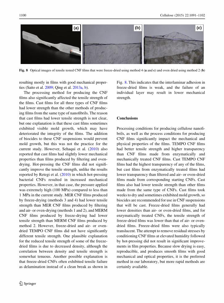
somewhat tenuous. Another possible explanation is
that freeze-dried CNFs often exhibited tensile failure
as delamination instead of a clean break as shown in
Fig. 8. This indicates that the interlaminar adhesion in
freeze-dried films is weak, and the failure of an
individual layer may result in lower mechanical
strength.
Conclusions
Processing conditions for producing cellulose nanofi-
brils, as well as the process conditions for producing
CNF films significantly impact the mechanical and
physical properties of the films. TEMPO CNF films
had better tensile strength and higher transparency
than CNF films made from enzymatically and
mechanically treated CNF films. Cast TEMPO CNF
films had the highest transparency of any of the films,
but cast films from enzymatically treated films had
lower transparency than filtered and air- or oven-dried
films made from corresponding starting CNFs. Cast
films also had lower tensile strength than other films
made from the same type of CNFs. Cast films took
weeks to dry and sometimes exhibited mold growth, so
biocides are recommended for use in CNF suspensions
that will be cast. Freeze-dried films generally had
lower densities than air- or oven-dried films, and for
enzymatically treated CNFs, the tensile strength of
freeze-dried films was lower than that of air- or oven-
dried films. Freeze-dried films were also typically
translucent. The attempt to remove residual stresses by
conditioning CNF films at elevated humidity followed
by hot-pressing did not result in significant improve-
ments in film properties. Because slow drying is easy,
reproducible, and produces smooth films with good
mechanical and optical properties, it is the preferred
method in our laboratory, but more rapid methods are
certainly available.
Fig. 8 Optical images of tensile tested CNF films that were freeze-dried using method 4 (a and c) and oven dried using method 2 (b)
1100 Cellulose (2015) 22:1091–1102
123

Acknowledgments This work was financially supported by
Agriculture and Food Research Initiative Grant (No.
2011-67009-20056) from the USDA National Institute of
Food and Agriculture the Forestry, Industry Research Special
Funds for Public Welfare Project of China (201404604), and
Hunan Provincial Innovation Foundation for Postgraduate
(CX2014A013) from China. The authors gratefully
acknowledge Rick Reiner of the Forest Products Laboratory
for preparing and supplying TEMPO-oxidized cellulose
nanofibrils. Debby Sherman of DS Imaging is kindly
acknowledged for TEM imaging.
References
Aulin C, Gallstedt M, Lindstrom T (2010) Oxygen and oil
barrier properties of microfibrillated cellulose films and
coatings. Cellulose 17(3):559–574
Bhuiyan MTR, Hirai N, Sobue N (2000) Changes of crystallinity
in wood cellulose by heat treatment under dried and moist
conditions. J Wood Sci 46(6):431–436
Capadona JR, Berg OVD, Capadona LA, Schroeter M, Rowan
SJ, Tyler DJ, Weder C (2007) A versatile approach for the
processing of polymer nanocomposites with self-assem-
bled nanofiber templates. Nat Nanotechnol 2(12):765–769
Cheng Q, Wang S (2008) A method for testing the elastic
modulus of single cellulose fibrils via atomic force
microscopy. Compos A 39(12):1838–1843
Cheng Q, Wang S, Rials TG, Lee SH (2007) Physical and
mechanical properties of polyvinyl alcohol and polypro-
pylene composite materials reinforced with fibril aggre-
gates isolated from regenerated cellulose fibers. Cellulose
14(6):593–602
Dalmas F, Cavaile JY, Gauthier C, Chazeau L, Dendievel R
(2007) Viscoelastic behavior and electrical properties of
flexible nanofiber filled polymer nanocomposites. Influ-
ence of processing conditions. Compos Sci Technol
67(5):829–839
Fukuzumi H, Saito T, Iwata T, Kumamoto Y, Isogai A (2009)
Transparent and high gas barrier films of cellulose nanof-
ibers prepared by TEMPO-mediated oxidation. Biomac-
romolecules 10(1):162–165
Henriksson M, Berglund LA (2007) Structure and properties of
cellulose nanocomposite films containing melamine
formaldehyde. J Appl Polym Sci 106(4):2817–2824
Henriksson M, Berglund LA, Isaksson P, Lindstrom T, Nishino
T (2008) Cellulose nanopaper structure of high toughness.
Biomacromolecules 9(6):1579–1585
Herrick FW, Casebier RL, Hamilton JK, Sandberg KR (1983)
Microfibrillated cellulose: morphology and accessibility.
J Appl Polym Sci Appl Polym Symp 37(9):797–813
Iwamoto S, Kai W, Isogai A, Iwata T (2009) Elastic modulus of
single cellulose microfibrils from tunicate measured by
atomic force microscopy. Biomacromolecules 10(9):
2571–2576
Kummar V, Kothari SH (1999) Effect of compressional force on
the crystallinity of directly compressible cellulose excipi-
ents. Int J Pharm 177(2):173–182
Mark JE (ed) (2007) Physical properties of polymers handbook,
2nd edn. Springer, New York, pp 825–850
Nakagaito AN, Yano H (2005) Novel high-strength biocom-
posites based on micro fibrillated cellulose having nano-
order-unit web-like network structure. Appl Phys A
80(1):155–159
Nogi M, Iwamoto S, Nakagaito AN, Yano H (2009) Optically
transparent nanofiber paper. Adv Mater 21(16):1595–1598
Nystrom G, Mihranyan A, Razaq A, Lindstrom T, Nyholm L,
Strømme M (2010) A nanocellulose polypyrrole composite
based on microfibrillated cellulose from wood. J Phys
Chem B 114(12):4178–4182
Okahisa Y, Yoshida A, Miyaguchi S, Yano H (2009) Optically
transparent wood-cellulose nanocomposite as a base sub-
strate for flexible organic light-emitting diode displays.
Compos Sci Technol 69(11–12):1958–1961
Okamoto T, Meshisuka G (2010) The nanostructure of kraft
pulp 1: evaluation of various mild drying methods using
field e scanning electron microscopy. Cellulose
17(6):1171–1182
Olsson RT, Azizi Samir MAS, Salazar-Alvarez G, Belova L,
Strom V, Berglund LA, Ikkala O, Nogues J, Gedde UW
(2010) Making flexible magnetic aerogels and stiff mag-
netic nanopaper using cellulose nanofibrils as templates.
Nat Nanotechnol 5(8):584–588
Paakko M, Ankerfors M, Kosonen H, Nykanen A, Ahola S,
Osterberg M, Ruokolainen J, Laine J, Larsson PT, Ikkala
O, Lindstrom T (2007) Enzymatic hydrolysis combined
with mechanical shearing and high pressure homogeniza-
tion for nanoscale cellulose fibrils and strong gels. Bio-
macromolecules 8(6):1934–1941
Paakko M, Vapaavuori J, Silvennoinen R, Kosonen H, An-
kerfors M, Lindstrom T, Berglund LA, Ikkala O (2008)
Long and entangled native cellulose I nanofibers allow
flexible aerogels and hierarchically porous templates for
functionalities. Soft Matter 4(12):2492–2499
Peng Y, Gardner DJ, Han Y (2012) Drying cellulose nanofibrils:
in search of a suitable method. Cellulose 19(1):91–102
Qing Y, Sabo R, Wu Y, Cai Z (2013a) Resin impregnation of
cellulose nanofibril films facilitated by water swelling.
Cellulose 20(1):303–313
Qing Y, Sabo R, Zhu JY, Agarwal U, Cai Z, Wu Y (2013b) A
comparative study of cellulose nanofibrils disintegrated via
multiple processing approaches. Carbohydr Polym
97(1):226–234
Retegi A, Gabilondo N, Pena C, Zuluaga R, Castro C, Ganan P,
de la Caba K, Mondragon I (2010) Bacterial cellulose films
with controlled microstructure–mechanical property rela-
tionship. Cellulose 17(3):661–669
Rodionova G, Eriksen Ø, Gregersen Ø (2012) TEMPO-oxidized
cellulose nanofiber films: effect of surface morphology on
water resistance. Cellulose 19(4):1115–1123
Sabo R, Seo JH, Ma Z (2012) Cellulose nanofiber composite
substrates for flexible electronics. In: 2012 TAPPI inter-
national conference on nanotechnology for renewable
materials, Montreal, QC
Saito T, Hirota M, Tamura N, Kimura S, Fukuzumi H, Heux L,
Isogai A (2009) Individualization of nano-sized plant cel-
lulose fibrils by direct surface carboxylation using TEMPO
catalyst under neutral conditions. Biomacromecules
10(7):1992–1996
Segal L, Creely JJ, Martin AE Jr, Conrad CM (1962) An
empirical method for estimating the degree of crystallinity
Cellulose (2015) 22:1091–1102 1101
123

of native cellulose using the X-ray diffractometer. Text Res
J 29(10):786–794
Sehaqui H, Liu A, Zhou Q, Berglund LA (2010) Fast preparation
procedure for large, flat cellulose and cellulose/inorganic
nanopaper structures. Biomacromolecules 11(9):2195–
2198
Sehaqui H, Mushi NE, Morimune S, Salajkova M, Nishino T,
Berglund LA (2012) Cellulose nanofiber orientation in
nanopaper and nanocomposites by cold drawing. ACS
Appl Mater Interfaces 4(2):1043–1049
Siro I, Plackett D (2010) Microfibrillated cellulose and new
nanocomposites materials: a review. Cellulose 17(3):459–
494
Spence KL, Venditti RA, Habibi Y, Rojas OJ, Pawlak JJ (2010)
The effect of chemical composition on microfibrillar cel-
lulose films from wood pulps: mechanical processing and
physical properties. Bioresour Technol 101(15):5961–
5968
Svagan AJ, Jensen P, Dvinskikh SV, Furo I, Berglund LA
(2010) Towards tailored hierarchical structures in cellulose
nanocomposite biofoams prepared by freezing/freeze-
drying. J Mater Chem 20(32):6646–6654
Tonoli GHD, Teixeira EM, Correa AC, Marconcini JM, Caixeta
LA, Pereira-da-Silva MA, Mattoso LHC (2012) Cellulose
micro/nanofibers from eucalyptus kraft pulp: preparation
and properties. Carbohyd Polym 89(1):80–88
Turbak A, Snyder FW, Sandberg KR (1983) Microfibrillated
cellulose, a new cellulose product: properties, uses, and
commercial potential. J Appl Polym Sci Appl Polym Symp
37(9):815–827
Uddin AJ, Araki J, Gotoh Y (2011) Toward ‘‘strong’’ green
nanocomposites: polyvinyl alcohol reinforced with extre-
mely oriented cellulose whiskers. Biomacromolecules
12(3):617–624
Xhanari K, Syverud K, Chinga-Carrasco G, Paso K, Stenius P
(2011) Reduction of water wettability of nanofibrillated
cellulose by adsorption of cationic surfactants. Cellulose
18(2):257–270
1102 Cellulose (2015) 22:1091–1102
123