SELECTRONIC AUSTRALIA WM1200-12V OWNERS MANUAL · WM1200-12V OWNERS MANUAL Contents: Page ... this...
17
SELECTRONIC AUSTRALIA WM1200-12V OWNERS MANUAL Contents: Page INTRODUCTION ............................................................................................................................... 2 WARRANTY CARD ............................................................................................................................ 2 INSTALLATION ................................................................................................................................. 2 SYSTEM DIAGRAM .......................................................................................................................... 3 BATTERIES ............................................................................................................................................................. 3 CONNECTION OF AC AND DC WIRING .......................................................................................................... 4 OPERATION ....................................................................................................................................... 5 MODE BUTTON & LED’s ..................................................................................................................................... 5 STATUS & ALARM INDICATORS - LED 5 (green) OFF ................................................................................. 6 DEMAND START ADJUST - LED 5 (green) ON................................................................................................. 6 LOW VOLTS ADJUST - LED 5 (green) FLASHING.......................................................................................... 7 HANDY HINT ..................................................................................................................................... 7 FAULT FINDING .............................................................................................................................. 8 SYSTEM MAINTENANCE ................................................................................................................ 9 WM1200 MAINTENANCE..................................................................................................................................... 9 BATTERY MAINTENANCE ................................................................................................................................. 9 WM1200 ELECTRICAL SPECIFICATIONS ................................................................................. 10 RADIO FREQUENCY INTERFERENCE ...................................................................................... 11 USING A SELECTRONIC KEYPAD WITH THE WM1200-12 .................................................... 12 SERIAL PORT WIRING ...................................................................................................................................... 12 KEYPAD WIRING ................................................................................................................................................ 12 KEYPAD FRONT PANEL (Display not shown for clarity) ............................................................................... 12 STATUS .................................................................................................................................................................. 13 READINGS (Keypad Grey Keys) ......................................................................................................................... 13 SETTINGS (Keypad Light Blue Keys) ................................................................................................................. 14 OPTIONS (Keypad Light Blue Keys) ................................................................................................................... 15 DIAGNOSTICS (Keypad Light Blue Keys) ......................................................................................................... 15 INVERTER ALARMS........................................................................................................................................... 15 WARNING ......................................................................................................................................... 16 PRODUCT WARRANTY and CONDITIONS ................................................................................. 16 SELECTRONIC AUTHORISED SERVICE NETWORK .............................................................. 17 1
-
Upload
truonghuong -
Category
Documents
-
view
214 -
download
0
Transcript of SELECTRONIC AUSTRALIA WM1200-12V OWNERS MANUAL · WM1200-12V OWNERS MANUAL Contents: Page ... this...

SELECTRONIC AUSTRALIA
WM1200-12V OWNERS MANUAL
Contents: Page
INTRODUCTION ...............................................................................................................................2
WARRANTY CARD ............................................................................................................................2
INSTALLATION.................................................................................................................................2
SYSTEM DIAGRAM ..........................................................................................................................3 BATTERIES .............................................................................................................................................................3 CONNECTION OF AC AND DC WIRING..........................................................................................................4
OPERATION.......................................................................................................................................5 MODE BUTTON & LED’s .....................................................................................................................................5 STATUS & ALARM INDICATORS - LED 5 (green) OFF .................................................................................6 DEMAND START ADJUST - LED 5 (green) ON.................................................................................................6 LOW VOLTS ADJUST - LED 5 (green) FLASHING..........................................................................................7
HANDY HINT.....................................................................................................................................7
FAULT FINDING ..............................................................................................................................8
SYSTEM MAINTENANCE................................................................................................................9 WM1200 MAINTENANCE.....................................................................................................................................9 BATTERY MAINTENANCE .................................................................................................................................9
WM1200 ELECTRICAL SPECIFICATIONS.................................................................................10
RADIO FREQUENCY INTERFERENCE......................................................................................11
USING A SELECTRONIC KEYPAD WITH THE WM1200-12 ....................................................12 SERIAL PORT WIRING ......................................................................................................................................12 KEYPAD WIRING ................................................................................................................................................12 KEYPAD FRONT PANEL (Display not shown for clarity)...............................................................................12 STATUS ..................................................................................................................................................................13 READINGS (Keypad Grey Keys) .........................................................................................................................13 SETTINGS (Keypad Light Blue Keys).................................................................................................................14 OPTIONS (Keypad Light Blue Keys)...................................................................................................................15 DIAGNOSTICS (Keypad Light Blue Keys).........................................................................................................15 INVERTER ALARMS...........................................................................................................................................15
WARNING.........................................................................................................................................16
PRODUCT WARRANTY and CONDITIONS.................................................................................16
SELECTRONIC AUTHORISED SERVICE NETWORK ..............................................................17
1

INTRODUCTION Thank you for your purchase of the Selectronic Sine wave inverter, model WM1200-12V. Your WM1200 is a state-of-the-art high performance TRUE SINE WAVE DC-AC Inverter.
Many hours of development time have been invested in the WM1200 so that we can provide you with a reliable high quality inverter. The output from your WM1200 is as good as, if not better than mains power. If looked after properly, the WM1200 will give you many years of reliable service.
WARRANTY CARD Before proceeding any further, it is extremely important that you complete your warranty card NOW. This will enable us to immediately register your 5 year warranty period. By accurately completing your warranty card, you will provide us with valuable information that will assist us in keeping up with your alternative energy needs. Please take a few moments to fill in the warranty card. Your efforts will be greatly appreciated.
INSTALLATION The installation of your inverter is extremely important. Failure to follow the recommended installation instructions may void your warranty. If in doubt, ask your supplier.
After unpacking, check for any damage that may have occurred during transit. If there are any signs of damage, contact your supplier immediately.
The Inverter must be installed in a dry, cool, dust-free environment.
Please leave at least 300mm clearance around the sides and top of the Inverter and approximately 200mm at the base as this will aid the natural cooling of the Inverter. The air vents on the underside of the WM1200 also need to be kept clear of obstructions.
BASE
300mm
300mm
Mode
PROUDLY DESIGNED & MADE IN AUSTRALIA
Demand Start Adjust
Low Volts Adjust
Alarms
DC POWER
4 Watts
DC Volts Low/High
TEMP Over load
8 Watts
DC TO AC POWER
STATUSAC Vo lts ON
AC Overload12 Watts
16 Watts
Off
ONDEMAND START
30mm
160mm
385mm
We suggest that you house your Inverter and other power generating equipment in a purpose built shed sited remotely from the home, and as far away as possible from any radio transmitters or receivers. Also make sure that the exhaust from your generator or other sources of heat or fumes are kept well away from the WM1200. SEIA (Sustainable Energy Industry Association (Australia) Ltd) installation guidelines must be followed. You must have a suitable 12V DC battery bank that is maintained and operated to the battery manufacturer’s recommendation. To ensure operation to WM1200 specification, the battery bank should have a minimum capacity of 500 ampere hours at the 100 hour discharge rate 12V systems (ask your supplier if in doubt). Smaller capacity batteries can be used but may result in degraded performance of the WM1200 under heavy surge conditions.
2

SYSTEM DIAGRAM
Inverter
Solar Panel
Diesel Generator
Wind Turbine
Battery Bank
Regulator
Regulator
Regulator
Installation Example
BatteryBank
System Fuse
RFI Ground
Mains Earth
Fuse / CBANE
Main Switch Earth Leakage CBA
N
EELCB ProtectedCircuits
+
+ -
-
*SYSTEM FUSE A system fuse is an extremely important part of any power system, this fuse is designed to give one point of complete disconnect in case of a serious fault. The fuse should have a sufficient rating so as not to blow under heavy load conditions. Your inverter will normally be the biggest load in your system, if this is the case a motor start fuse equal to or slightly higher than the maximum continuous current of the inverter should be used. If in any doubt see your supplier or installer.
BATTERIES High quality deep-cycle batteries offer good performance and are available in a wide variety of sizes. DO NOT USE ordinary car batteries or engine starting batteries. If a battery is rated only in Cold Cranking Amps (CCA) and reserve capacity, it is designed to start an engine. Most hybrid type, wet cell batteries will have a limited life if deeply discharged. These batteries are described as suitable for engine starting or deep-cycle applications. Do not use maintenance free, wet cell batteries. They will not hold up well to deep discharging and repeated cycling.
3

CONNECTION OF AC AND DC WIRING IMPORTANT: Before making any wiring connections, check that the circuit breaker on the front panel is in the OFF position, i.e.; LEVER DOWN.
Your electrician should firstly connect the AC wiring via the three terminal junction box. Carefully observe the correct connections. Please refer to the diagram on page 4. BROWN ACTIVE (red dot, right connector) GREEN/YELLOW EARTH (E, centre connector) BLUE NEUTRAL (left connector)
The lid of the junction box has knockouts to allow conduit entry. Make sure this connection is tight and safe. Re fit junction box cover.
NOTE: ALL AC WIRING MUST BE CARRIED OUT BY A LICENSED ELECTRICIAN AND MUST
CONFORM TO AS3000 WIRING REGULATIONS, OR RELEVANT STANDARDS.
Verify that the circuit breaker on the front panel is in the OFF position, LEVER DOWN. Now connect the battery cables. RED BATTERY POSITIVE (+) BLACK BATTERY NEGATIVE (-) These connections should be tight. If using nuts, bolts and washers, they should be stainless steel. At this point re-check the connections before proceeding any further.
WARNING:
IF THE WM1200 EMITS A VERY LOUD TONE, THE BATTERY LEADS HAVE BEEN CONNECTED IN REVERSE POLARITY. IMMEDIATELY DISCONNECT THE LEADS AND RECONNECT WITH THE CORRECT POLARITY. DO NOT, UNDER ANY CIRCUMSTANCES, TURN ON THE BREAKER WHEN THE BUZZER IS SOUNDING, AS PERMANENT DAMAGE TO THE WM1200 WILL RESULT. If all is well you can now switch the circuit breaker ON.
Mode
PROUDLY DESIGNED & MADE IN AUSTRALIA
Demand Start Adjust
Low Volts Adjust
Alarms
DC POWER
4 Watts
DC Volts Low/High
TEMP Overload
8 Watts
DC TO AC POWER
STATUSAC Volts ON
AC Overload12 Watts
16 Watts
Off
ON
DEMAND START
Front Panel
SERIAL JUNCTION BOX
RATINGS LABEL
N E A
Base
4
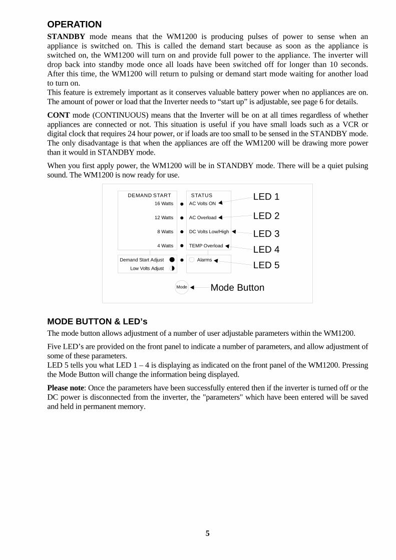
OPERATION STANDBY mode means that the WM1200 is producing pulses of power to sense when an appliance is switched on. This is called the demand start because as soon as the appliance is switched on, the WM1200 will turn on and provide full power to the appliance. The inverter will drop back into standby mode once all loads have been switched off for longer than 10 seconds. After this time, the WM1200 will return to pulsing or demand start mode waiting for another load to turn on. This feature is extremely important as it conserves valuable battery power when no appliances are on. The amount of power or load that the Inverter needs to “start up” is adjustable, see page 6 for details.
CONT mode (CONTINUOUS) means that the Inverter will be on at all times regardless of whether appliances are connected or not. This situation is useful if you have small loads such as a VCR or digital clock that requires 24 hour power, or if loads are too small to be sensed in the STANDBY mode. The only disadvantage is that when the appliances are off the WM1200 will be drawing more power than it would in STANDBY mode.
When you first apply power, the WM1200 will be in STANDBY mode. There will be a quiet pulsing sound. The WM1200 is now ready for use.
Mode
Demand Start Adjust
Low Volts Adjust
Alarms
4 Watts
DC Volts Low/High
TEMP Overload
8 Watts
STATUSAC Volts ON
AC Overload12 Watts
16 Watts
DEMAND START LED 1
LED 2
LED 3LED 4LED 5
Mode Button
MODE BUTTON & LED’s The mode button allows adjustment of a number of user adjustable parameters within the WM1200.
Five LED’s are provided on the front panel to indicate a number of parameters, and allow adjustment of some of these parameters. LED 5 tells you what LED 1 – 4 is displaying as indicated on the front panel of the WM1200. Pressing the Mode Button will change the information being displayed.
Please note: Once the parameters have been successfully entered then if the inverter is turned off or the DC power is disconnected from the inverter, the "parameters" which have been entered will be saved and held in permanent memory.
5

STATUS & ALARM INDICATORS - LED 5 (green) OFF
When power is first applied LED 1 should flash.
When LED 5 is OFF, this indicates the LED (1) – (4) is showing the inverters STATUS, as per written notation to the right of the LED’s. In this mode there are no adjustments to be made.
LED 1 Flashing indicates the WM1200 is in Auto Start mode, this indicates that no power is being drawn from the inverter so it has gone to SLEEP to save power. If no power is used within 12 minutes, LED 1 will flash at a slower rate therefore saving more power.
LED 1 Stays ON, the inverter has been commanded to provide power to the load (e.g. a light switch has been turned on) so it has gone from SLEEP mode to ON. Once the load has been removed (e.g. the light switch is turned off) the inverter will wait 10 seconds and return to SLEEP mode. • It is good practice to have your WM1200 in SLEEP mode as often as possible. When the
WM1200 is in SLEEP mode it uses 0.055 amps from the battery, when the inverter is in the ON mode it uses at least 0.6 amps from the battery.
The amount of power required to go from SLEEP to ON is adjustable and is described on below.
LED 2, AC Overload should normally remain OFF. If the inverter shuts down due to too much AC load being drawn from it then LED 2 will come ON. The WM1200 will remain in this condition for 2 minutes after the AC load has been decreased to a safe level. LED 2 will flash if the inverter shuts down due to “time to shutdown”, see page 11. • If the inverter remains in this condition after two minutes, the main DC Power Switch should be
turned OFF and then back ON.
LED 3 DC Volts Low / High should normally remain OFF. If the inverter shuts down because the battery volts are too high then this LED will come ON. It will remain ON until normal battery volts are restored. • If the inverter shuts down due to not enough battery volts, then LED 3 will flash. • LED 3 will continue to flash until the battery volts have risen sufficiently. In this case, charge the
battery by starting the vehicle or using a battery charger. The low voltage point that the inverter will cut out is adjustable to suit your particular battery.
LED 4, Temperature Overload should normally remain OFF. If the inverter shuts down due to the heatsink getting too hot, then this LED will come ON. If the inverter shuts down due to the transformer getting too hot, then this LED will FLASH. The inverter will remain shut down until the temperature has lowered to a safe level; the inverter will then come back ON. • If this LED is coming on regularly, either reduce the amount of load on the inverter or try to move
the inverter to a cooler location.
DEMAND START ADJUST - LED 5 (green) ON It is sometimes necessary to adjust the auto start sensitivity to overcome what is called “Phantom Loads”. A phantom load is a load that tricks the inverter into thinking it should be ON instead of in SLEEP mode. The wiring of a house or a portable stereo system in standby are good examples of a phantom load. These loads serve no purpose but can increase battery drain by bringing the inverter ON. Hold the Mode button down, (approximately 1 second), LED 5 will turn ON indicating you are ready to adjust this setting. The WM1200 will leave the factory with a setting of 4 Watts. Now press the Mode button until the desired value is sought. LED’s 1 – 4 will return to Status Indication after 10 seconds if a key is not pressed. • Each press of the Mode Button will increment the Demand Start Level. The adjustment starts from
the previously stored setting.
6

LED 1 - 4, Demand Start Adjustment is indicated by LEDS 1 – 4. Demand Start Wattage LED 1 LED 2 LED 3 LED 4 4 Watts ON 5 Watts Slow flash ON 6 Watts Medium flash ON 7 Watts Fast flash ON 8 Watts ON 9 Watts Slow flash ON 10 Watts Medium flash ON 11 Watts Fast flash ON 12 Watts ON 13 Watts Slow flash ON 14 Watts Medium flash ON 15 Watts Fast flash ON 16 Watts ON Continuous ON ON ON ON
After “continuous”, the next button press “rolls back” the demand start setting to 4 Watts
LOW VOLTS ADJUST - LED 5 (green) FLASHING To avoid total discharging of your battery the WM1200 shuts down at a pre-set low voltage. As all batteries are different, so too is the minimum voltage they should be discharged to. The WM1200 will leave the factory with a setting of 11.0 Volts, change this setting if required. From Demand Start Adjust, page 6, hold the Mode button down, (approximately 1 second), until LED 5 is FLASHING, indicating you are ready to adjust this setting. Now press the Mode button until the desired value is sought. LED’s 1 – 4 will return to Status Indication after 10 seconds if a key is not pressed.
Low Volts Cut-out LED 1 LED 2 LED 3 LED 4 10.0 Volts ON 10.1 Volts Slow flash ON 10.2 Volts Medium flash ON 10.3 Volts Fast flash ON 10.4 Volts Fastest flash ON 10.5 Volts ON 10.6 Volts Slow flash ON 10.7 Volts Medium flash ON 10.8 Volts Fast flash ON 10.9 Volts Fastest flash ON 11.0 Volts ON 11.1 Volts Slow flash ON 11.2 Volts Medium flash ON 11.3 Volts Fast flash ON 11.4 Volts Fastest flash ON 11.5 Volts ON
After “11.5 Volts”, the next button press “rolls back” the Low DC Volts Cut-out setting to “10.0 Volts”
HANDY HINT It is very important that you become familiar with the functioning of your Inverter. Since most Inverters are not within sight, it is not always easy to know what STATUS your inverter is in. An easy way to determine this is to plug a small child's night-light (neon type) into a power point that is easily visible, or replace any power point with a neon indicator type. This will indicate the inverter's operation by flashing when the inverter is pulsing and remaining on when the inverter is brought on by a load.
7

FAULT FINDING 1. INVERTER STAYS ON EVEN WHEN NO APPLIANCE IS BEING USED. Some appliances such as Microwave Cookers or Video Recorders still draw current when not in use. This is to power their displays. This is a common problem known as a "phantom load", but it can be easily overcome with the WM1200. When trying to isolate a phantom load these appliances will need to be switched off at the power point. Sequentially switch off appliances at their power points while checking to see if the inverter returns to demand start mode after a 10 second delay. See “Handy Hint” on page 7 if your inverter is located remotely. Once you have found the offending appliance, adjust the sensitivity of the demand start up (see page 6) until the Inverter turns off. Once this is done re check that small loads will still bring the Inverter on when required. 2. INVERTER WILL NOT COME ON WHEN SMALL APPLIANCE IS SWITCHED ON. This means that your demand start sensitivity is set too high. With the appliance in question switched on, adjust the demand start sensitivity (see page 6) until the WM1200 turns on. 3. INVERTER SHUTS DOWN DURING MIDDLE OF THE DAY AND COMES BACK ON LATE AFTERNOON. This is more than likely caused by high battery volts during peak charging times from solar panels. Battery volts should never exceed 17 volts. If this is the case, have your Solar Regulator checked. This could be potentially dangerous so we advise you to consult your system designer immediately. 4. INVERTER SHUTS DOWN WITH LOW VOLTS. If your WM1200 has shut down because of low DC volts it could be due to the following: (1) A sustained large load could be causing the battery volts to drop below the cut out voltage.
(a) The Battery Bank is too small for the loads you wish to use - consult your system designer. (b) A bad connection between the batteries and inverter due to a loose or corroded terminal. In
this case, please refer to the maintenance section of this manual. (c) One or more battery cells could be faulty - consult your battery supplier.
(2) If your battery volts are below 12.0V with no loads connected, the batteries may require charging. Use a hydrometer to check the specific gravity of each cell. Consult your battery manual for the correct specific gravity (SG) readings.
5. INVERTER SHUTS DOWN DUE TO HS TOO HOT This is likely under sustained heavy load conditions since the WM1200 shuts down to protect its internal components. If you believe that the load is not excessive, check around the Inverter case and heatsink for obstructions to airflow as this will cause the Inverter to heat up much quicker and shut down sooner than normal. Also check that the clearances around the WM1200 are as specified in the INSTALLATION section of this manual. 6. INVERTER PULSES SLOWER THAN NORMAL WHEN IN STANDBY This means that the inverter has not been switched on for approximately 20 minutes and has gone into a power saving mode, thus pulsing at about half the normal rate.
8

SYSTEM MAINTENANCE To get the optimum performance from your WM1200 power inverter, particularly under heavy appliance loads, it is essential that the battery bank and the DC wiring are all in good condition. The small amount of time spent on the maintenance tasks below will maximise the reliability of your system.
WM1200 MAINTENANCE Periodic maintenance of the WM1200 inverter involves little more than checking for unobstructed operation of the cooling fans, which are located on the sides of the inverter. Note that cooling air is drawn in through the vents in the side of the inverter. Suggested inverter maintenance should include: 1. Check for unobstructed fan operation:
Clear away any dust or foreign matter from the fan grill using a soft bristled brush. (Do not direct high-pressure compressed air at the fan blades) Note that the fan is designed to come on during heavy power demand.
2. Check between fins of the heatsink and clean out any accumulated foreign objects, for example,
insect nests.
BATTERY MAINTENANCE IMPORTANT: When working on batteries of such high capacity it is essential that you wear protective clothing, some form of eye protection and rubber-soled work boots. Please regard your batteries with a great deal of caution, and if in any doubt, entrust this work to your installer. 1. Every week, carry out a thorough visual inspection of all battery wiring, taking particular note
of the condition of inter-connections between cells. 2. Check that the stainless steel inter-connecting bolts are tight and have minimal corrosion. If
corrosion is evident, carefully follow the following procedure.
(a) Disconnect the system battery fuse before working on the battery bank.
(b) Unbolt the stainless steel bolts and nuts of any corroded connections and thoroughly clean the joint with a wire brush or file, taking extreme care not to short circuit any battery cells with any tools.
(d) Re-assemble and smear a small amount of Vaseline or similar grease over the surface of the joint to slow down any future corrosion.
3. Every month or as directed in your battery instruction manual, measure the specific gravity (SG)
of each cell using your hydrometer, to ensure that all cells are performing correctly. Any serious imbalance should be reported to your system designer in case remedial action needs to be taken.
9

WM1200 ELECTRICAL SPECIFICATIONS INVERTER TYPE PWM Full Bridge power stage, with true sine wave AC output.
SELECTRONIC WM1200 INVERTER SPECIFICATIONS ELECTRICAL PARAMETER WM1200 CONDITION Output Power @ 25 °C Ambient
1,400 watts 1,800 watts 3,600 watts
Max Continuous 1/2 Hour Rating Max Surge
Output Power @ 40 °C Ambient
1,200 watts 1,600 watts 3,600 watts
Max Continuous 1/2 Hour Rating Max Surge
Voltage Input Range 10 - 17V DC Range Input Current 0.05A DC
0.7A DC 136A DC 349A DC
Stand By Inverter ON – No Load Max Continuous 25°C Max Surge 25°C
Demand Start Sensitivity Response Time Factory Setting
4-16W 1 Second Max
4W
User Adjustable Factory Setting
Low Voltage Shutdown High Voltage Shutdown Factory Setting (Low Voltage Shutdown)
10 – 11.5V DC 17V DC
11.0V DC
User Adjustable Fixed Factory Setting
Output Voltage 240V AC +/- 4% @ Nominal DC Input, No Load to Full Load
Output Current 5.8A AC 15A AC
Max Continuous Max Surge
Output Wave Shape Output Frequency Total Harmonic Distortion Efficiency
True Sine Wave 50Hz +/- 0.01%
< 4% Peak 91% Full load 85%
Power Factor Limitations Nil Input / Output Isolation 1,875VAC Memory Retention Permanent Operating Temperature Range -10 °C to 50 °C Conforms to standards AS 3100 (wiring), AS 3108, C tick MECHANICAL Size 410mm wide x 175mm high x 342mm deep Weight 14kg Weight Packed 17kg Input Lead Length 1.5 metres Output Wiring Method Three terminal junction box with conduit knock outs Chassis Powder coated zinc steel (Wedgwood Blue) DC Isolation Single Pole Circuit Breaker ( Non auto ) Warranty 5 year parts and labour (Conditions apply) Notes: The above specifications are based on unity power factor. The DC Input is electrically isolated from the AC Output. Through a policy of continued development, specifications are subject to change without notice
10

RADIO FREQUENCY INTERFERENCE Radio Frequency Interference (RFI) can be a problem for owners of inverters. RFI in a domestic situation may produce noise or interference on a radio or TV receiver. Considerable development time has resulted in a reduction of the RFI generated by the inverter to a level that complies with C-tick requirements. Compliance to this standard means RFI is low, but how well the inverter performs in a particular installation can vary. Below are some suggestions to help reduce the effects of RFI in your installation;
• It is recommended that the power system, including the inverter, be housed at least 15 metres from the home.
• Ensure an earth stake is placed as close to the inverter as possible and connected to the inverter
via a short length of wire. See the “INSTALLATION” section of this manual for wiring.
• Avoid running DC cables into the home, if at all possible. If this cannot be avoided, run DC and AC in separate conduits separated by as much distance as practicable. All DC wiring cables should be kept together and be as short as possible.
• If your inverter is to be installed in a Mobile Home or similar, try to keep your inverter at least
one metre away from your radio or audio equipment. The further the better.
11

USING A SELECTRONIC KEYPAD WITH THE WM1200-12
SERIAL PORT WIRING Serial Port
Pin Number Data Cable Wire Colour Function
1 White with green stripe Transmit + 2 Green Transmit - 3 White with orange stripe Receive + 4 Blue +15V 5 White with blue stripe 0V 6 Orange Receive - 7 White with brown stripe 8 Brown
RATINGS LABEL
Serial Port
1
8
KEYPAD WIRING
Serial Port(looking at the base of the inverter)
12345678Keypad (from rear)
123456
KEYPAD FRONT PANEL (Display not shown for clarity)
NEXTDISPLAY UP DOWN
SETTINGS OPTIONS DIAG-NOSTICS
CURRENTSHUNT 1
CURRENTSHUNT 2
CURRENTSHUNT 3
AC LOADREADINGS
INPUTREADINGS
GENERATORCONTROL
INVERTERSTATUS TIME BATTERY
READINGS
ALARM
Remote KeypadEnergy Management MkII
Keypad Grey Keys
Keypad Light Blue Keys
Keypad Dark Blue Keys
12

STATUS When you turn on the WM1200 with a keypad installed, the keypad screen will be displayed. Press NEXT DISPLAY twice.
Press NEXT twice WM1200 1.00 2000
The inverter STATUS will be displayed. The inverter can have one of three status conditions. When first turned on it will show STANDBY mode.
Status: STANDBY Inverter: ON
Status: CONT Inverter: ON
Status: RESET Inverter: OFF
When this screen is displayed, the Status can be changed by pressing the UP or DOWN arrow keys. Each time the UP key is pressed, the status will change from STANDBY to CONT to RESET and back to STANDBY where the DOWN key will change the Status in the reverse order. The second line indicates if the inverter is ON or OFF. When ON the inverter is supplying 240V mains power. During standby, OFF is displayed on the second line, reverting to ON when a load is sensed and the inverter starts. STANDBY mode means that the WM1200 is producing pulses of power to sense when an appliance is switched on. This is called the demand start because as soon as the appliance is switched on, the WM1200 will turn on and provide full power to the appliance. The inverter will drop back into standby mode once all loads have been switched off for longer than 10 seconds. After this time, the WM1200 will return to pulsing or demand start mode waiting for another load to turn on. This feature is extremely important as it conserves valuable battery power when no appliances are on. The amount of power or load that the Inverter needs to “start up” is adjustable, see page 5 for details. CONT mode (CONTINUOUS) means that the Inverter will be on at all times regardless of whether appliances are connected or not. This situation is useful if you have small loads such as a VCR or digital clock that requires 24 hour power, or if loads are too small to be sensed in the STANDBY mode. The only disadvantage is that when the appliances are off the WM1200 will be drawing more power than it would in STANDBY mode. RESET mode electronically shuts down the inverter. When placed in this mode, any overload or shutdown conditions are also reset. This situation will be explained in more detail in a later section.
READINGS (Keypad Grey Keys) The displays provide the following information: Press the indicated Keypad Grey Key. Battery Readings
Displays the DC Battery volts. This provides you with an indication of the condition of your battery bank. Time of Day
DC Volts:13.7V --- Readings ---
AC Load readings This reading gives an indication of the AC voltage produced by the inverter. This reading will vary depending on how large a load is connected or if the battery voltage is very low. Pressing the AC LOAD READINGS button again will move you to the next “AC Amps” screen.
AC Volts : 240V --- Readings ---
AC Load readings (second button press)
13

The AC Amps reading shows the total current drawn from the AC output by the appliances connected to the inverter. This reading is also handy for knowing how much power a particular appliance draws. Pressing the AC LOAD READINGS button again will move back to the previous “AC Volts” screen.
AC Amps : 2.5A --- Readings ---
Other Keypad grey keys Pressing any of the keys “TIME”, “GENERATOR CONTROL”, “INPUT
READINGS”, “CURRENT SHUNT 1”, “CURRENT SHUNT 2”, “CURRENT SHUNT 3”, will result in this screen being displayed. The functions are not available on the WM1200
Not Installed
SETTINGS (Keypad Light Blue Keys) Press the Keypad SETTINGS Light Blue Key, then the ENTER Dark Blue Key. Please note: Once the parameters have been successfully entered (i.e. you have stepped right through the set parameters menu) then if the inverter is turned off or the DC power is disconnected from the inverter, the "parameters" which have been entered will be saved and held in permanent memory. KEYPAD BUZZER
This display allows you to select whether the keypad audio alarm will sound during an overload or other alarm condition. Use the UP or DOWN keys to toggle between ON or OFF state. This is set to ON at the factory.
Buzzer : ON -Set Parameters-
DS SENSE
DS Watts :12W -Set Parameters-
Demand Start: When in STANDBY mode the inverter will require a load of 4 watts or greater to turn on to full 240V power. This setting can be adjusted between 4 to 16 watts. In most cases the default setting of 4W would be suitable. If there is a load which the WM1200 won't sense then increase this value until the WM1200 goes into demand start (pulsing mode). You may need to try a few different settings to find the most appropriate value for your installation. Use the UP or DOWN keys.
LO DC VOLTS The WM1200 will cut out and a message will be displayed if the battery
voltage falls below this setting for more than 10 seconds. The inverter will restart if reset, or when the battery volts rise above 11.5V. Use the UP or DOWN keys to change the value. Default values are 11.0 volts for 12V operation.
Lo DC Volts:11.0 -Set Parameters-
AC OUTPUT VOLTS Allows the AC output voltage to be set in a range of 220V to 240V if an
output voltage other than 240V is required. Users outside Australia should check with their system designer for the correct setting. Use the UP or DOWN keys to change the value. This value is set to 240V at the factory.
AC Volts : 240V -Set Parameters-
END SETTINGS -End- -Set Parameters-
Indicates the end of the set parameters menu. Press any grey keypad key to return you to the STATUS menu and save your settings.
14

OPTIONS (Keypad Light Blue Keys) Press the Keypad OPTIONS Light Blue Key. This display allows access to logged alarms.
Press the OPTIONS key to scroll through logged alarms. If there are no logged alarms, only this screen will be displayed. When in this END ALARMS screen, press any grey keypad key to return you to the STATUS menu.
-END- --Alarms--
Logged alarms are: • Low DC Volts • High DC Volts • AC Current Overload • Current Limit • High Transformer Temperature • High Heatsink Temperature
DIAGNOSTICS (Keypad Light Blue Keys) Press the Keypad DIAGNOSTICS Light Blue Key. The following screens allow the user to look at various internal inverter values. These are not able to be changed from the keypad.
Press NEXT key ..Diagnostics..
Press the NEXT key to access diagnostics screens.
Tx Temp.: 1 ..Diagnostics..
Indicates transformer temperature. Note the reading is NOT in degrees Celsius.
HS Temp: 53C ..Diagnostics..
Indicates Heatsink temperature. Note the reading IS in degrees Celsius.
D/S I: 2 ..Diagnostics..
Indicates Demand Start current level.
Selectronic C WM1200 1.00 2000
Indicates the Inverter model, microprocessor code revision and year. Press any grey keypad key to return you to the STATUS menu.
INVERTER ALARMS Inverter Alarms are not indicated on the keypad screen. The status of the inverter can be checked, along with the output voltages and currents. The Keypad LED will flash and the buzzer will sound on an Inverter Alarm.
15

WARNING
THE OUTPUT VOLTAGE FROM AN INVERTER IS JUST AS LETHAL AS LANDLINE POWER.
It is necessary for your safety to ensure that all Remote Area power system installations meet and comply with the relevant provisions and requirements of AS3000 wiring standards and AC wiring is installed by a Registered Electrical Contractor.
PRODUCT WARRANTY and CONDITIONS
Warranty
Selectronic Australia Pty Ltd warrants your inverter to be free from defects in materials and workmanship under normal use and service, for a period of five (5) years. Defective parts will be replaced or repaired free of charge within this period.
Conditions
This warranty is applicable only from the date of original purchase.
The provision of this warranty shall not apply if the unit has been subject to misuse, neglect, act of God, accidental damage or has been used for a purpose for which it is not intended.
Unauthorised modification or repair will void your warranty.
To ensure a smooth and speedy response to your warranty claim, please complete and return your reply paid warranty card within 30 days from date of purchase.
Within Australia & New Zealand
The inverter must be returned, at the owner’s cost, to an authorised service centre listed in this manual. There will be no charge for the return of the inverter.
Outside Australia & New Zealand
Product purchased for use outside Australia & New Zealand may only be returned to Selectronic Australia’s Service Centre to enable warranty claims to be processed. Freight cost to be borne by the customer. No charge will be made for the product return.
16
SELECTRONIC AUTHORISED SERVICE NETWORK
Selectronic Australia 25 Holloway Drive
Bayswater Victoria 3153
Australia Ph: 03 9762 4822 Fax: 03 9762 9646
Burley TV Service Rainbow Power Company 278 Edmondson Ave. 1 Alternative Way
Austral Nimbin NSW 2171 NSW 2480
Australia Australia Ph: 02 9606-0279 Ph: 02 6689 1430
Fax: 02 6689 1109 Reid Technology Ltd 3-5 Auburn Street
Solar Inverter Services Takapuna 13 Thirteenth Ave. North Shore City
Sawtell Auckland NZ NSW Ph: 9 489-8100 2452 Fax: 9 489-8585
Ph: 02 66581733 [email protected]
SELECTRONICAUSTRALIA
25 Holloway Drive Bayswater, Victoria 3153 AustraliaPhone 03 9762 4822 Fax 03 9762 9646 Email [email protected]
Part No ST-MWM1212 REV 2 24/02/04


![Untitled-2 [suntracbatteries.com]suntracbatteries.com/suntrac.pdf · capacity 12v 20ah 12v 40ah 12v 60ah 12v b40ah 12v b60ah 12v b80ah 12v biooah 12v 80ah 12v iooah 12v 130ah 12v](https://static.fdocuments.in/doc/165x107/603efb7aa12c32391f5484d1/untitled-2-capacity-12v-20ah-12v-40ah-12v-60ah-12v-b40ah-12v-b60ah-12v-b80ah.jpg)