Selective measurement of high frequency electro- … · SRM-3006 Selective measurement of high...
19
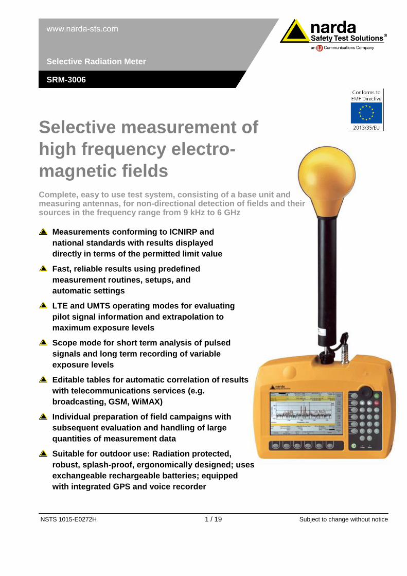
NSTS 1015-E0272H 1 / 19 Subject to change without notice Selective Radiation Meter SRM-3006 Selective measurement of high frequency electro- magnetic fields Complete, easy to use test system, consisting of a base unit and measuring antennas, for non-directional detection of fields and their sources in the frequency range from 9 kHz to 6 GHz Measurements conforming to ICNIRP and national standards with results displayed directly in terms of the permitted limit value Fast, reliable results using predefined measurement routines, setups, and automatic settings LTE and UMTS operating modes for evaluating pilot signal information and extrapolation to maximum exposure levels Scope mode for short term analysis of pulsed signals and long term recording of variable exposure levels Editable tables for automatic correlation of results with telecommunications services (e.g. broadcasting, GSM, WiMAX) Individual preparation of field campaigns with subsequent evaluation and handling of large quantities of measurement data Suitable for outdoor use: Radiation protected, robust, splash-proof, ergonomically designed; uses exchangeable rechargeable batteries; equipped with integrated GPS and voice recorder
-
Upload
dinhkhuong -
Category
Documents
-
view
217 -
download
2
Transcript of Selective measurement of high frequency electro- … · SRM-3006 Selective measurement of high...
NSTS 1015-E0272H 1 / 19 Subject to change without notice
Selective Radiation Meter
SRM-3006
Selective measurement of
high frequency electro-
magnetic fields Complete, easy to use test system, consisting of a base unit and measuring antennas, for non-directional detection of fields and their sources in the frequency range from 9 kHz to 6 GHz
Measurements conforming to ICNIRP and
national standards with results displayed
directly in terms of the permitted limit value
Fast, reliable results using predefined
measurement routines, setups, and
automatic settings
LTE and UMTS operating modes for evaluating
pilot signal information and extrapolation to
maximum exposure levels
Scope mode for short term analysis of pulsed
signals and long term recording of variable
exposure levels
Editable tables for automatic correlation of results
with telecommunications services (e.g.
broadcasting, GSM, WiMAX)
Individual preparation of field campaigns with
subsequent evaluation and handling of large
quantities of measurement data
Suitable for outdoor use: Radiation protected,
robust, splash-proof, ergonomically designed; uses
exchangeable rechargeable batteries; equipped
with integrated GPS and voice recorder
NSTS 1015-E0272H 2 / 19 Subject to change without notice
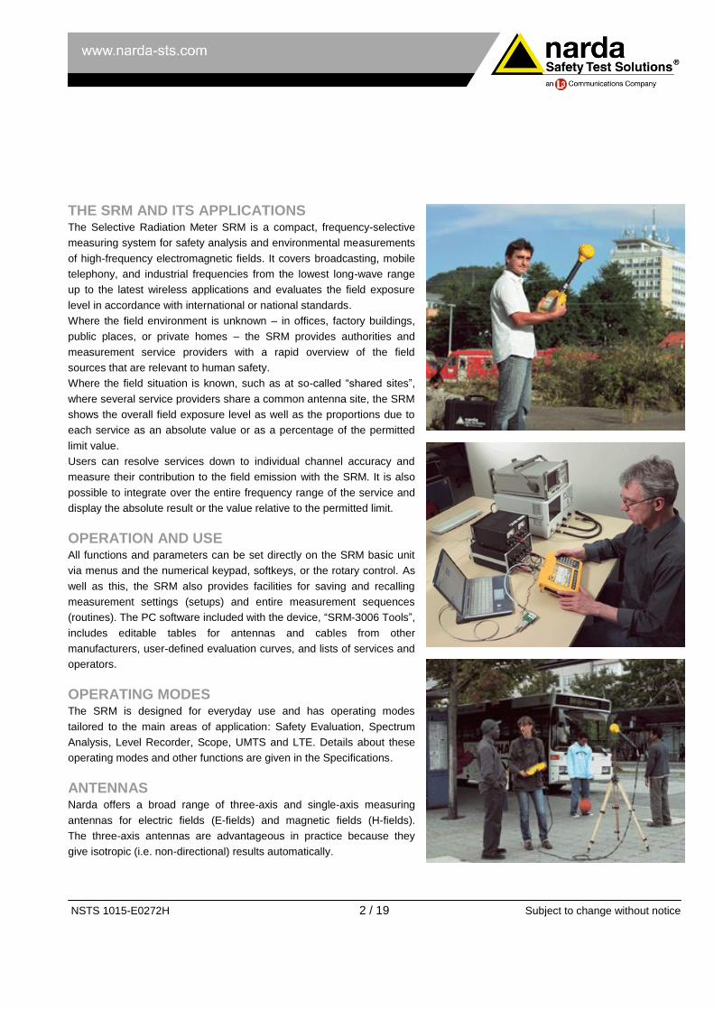
THE SRM AND ITS APPLICATIONS The Selective Radiation Meter SRM is a compact, frequency-selective
measuring system for safety analysis and environmental measurements
of high-frequency electromagnetic fields. It covers broadcasting, mobile
telephony, and industrial frequencies from the lowest long-wave range
up to the latest wireless applications and evaluates the field exposure
level in accordance with international or national standards.
Where the field environment is unknown – in offices, factory buildings,
public places, or private homes – the SRM provides authorities and
measurement service providers with a rapid overview of the field
sources that are relevant to human safety.
Where the field situation is known, such as at so-called “shared sites”,
where several service providers share a common antenna site, the SRM
shows the overall field exposure level as well as the proportions due to
each service as an absolute value or as a percentage of the permitted
limit value.
Users can resolve services down to individual channel accuracy and
measure their contribution to the field emission with the SRM. It is also
possible to integrate over the entire frequency range of the service and
display the absolute result or the value relative to the permitted limit.
OPERATION AND USE All functions and parameters can be set directly on the SRM basic unit
via menus and the numerical keypad, softkeys, or the rotary control. As
well as this, the SRM also provides facilities for saving and recalling
measurement settings (setups) and entire measurement sequences
(routines). The PC software included with the device, “SRM-3006 Tools”,
includes editable tables for antennas and cables from other
manufacturers, user-defined evaluation curves, and lists of services and
operators.
OPERATING MODES The SRM is designed for everyday use and has operating modes
tailored to the main areas of application: Safety Evaluation, Spectrum
Analysis, Level Recorder, Scope, UMTS and LTE. Details about these
operating modes and other functions are given in the Specifications.
ANTENNAS Narda offers a broad range of three-axis and single-axis measuring
antennas for electric fields (E-fields) and magnetic fields (H-fields).
The three-axis antennas are advantageous in practice because they
give isotropic (i.e. non-directional) results automatically.
NSTS 1015-E0272H 3 / 19 Subject to change without notice
DEFINITIONS AND CONDITIONS
Conditions
Unless otherwise noted, specifications apply after 30 minutes warm-up
time within the specified environmental conditions. The product is within
the recommended calibration cycle.
Specifications with limits
These describe product performance for the given parameter covered
by warranty. Specifications with limits (marked as <, ≤, >, ≥, ±, max.,
min.) apply under the given conditions for the product and are tested
during production taking measurement uncertainty into account.
Specifications without limits
These describe product performance for the given parameter covered
by warranty. Specifications without limits represent values with negligible
deviations which are ensured by design (e.g. dimensions or resolution of
a setting parameter).
Typical values (typ.)
These characterize product performance for the given parameter that is
not covered by warranty. When stated as a range or as a limit (marked
as <, ≤, >, ≥, ±, max., min.), they represent the performance met by
approximately 80 % of the instruments. Otherwise, they represent the
mean value. The measurement uncertainty is not taken into account.
Nominal values (nom.)
These characterize expected product performance for the given
parameter that is not covered by warranty. Nominal values are verified
during product development but are not tested during production.
Uncertainties
These characterize an interval for a given measurand estimated to have
a level of confidence of approximately 95 percent. Uncertainty is stated
as the standard uncertainty multiplied by the coverage factor k=2 based
on the normal distribution. The evaluation has been carried out in
accordance with the rules of the "Guide of the Expression of Uncertainty
in Measurement" (GUM).
NSTS 1015-E0272H 4 / 19 Subject to change without notice
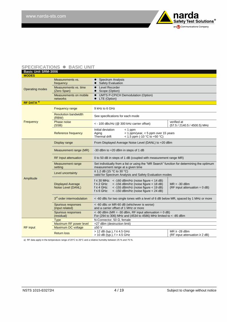
SPECIFICATIONS BASIC UNIT Basic Unit SRM-3006 MODES
Operating modes
Measurements vs. frequency
Spectrum Analysis Safety Evaluation
Measurements vs. time (Zero Span)
Level Recorder Scope (Option)
Measurements on mobile networks
UMTS P-CPICH Demodulation (Option) LTE (Option)
RF DATA a)
Frequency
Frequency range 9 kHz to 6 GHz
Resolution bandwidth (RBW)
See specifications for each mode
Phase noise
(SSB) < - 100 dBc/Hz (@ 300 kHz carrier offset)
verified at (57.5 / 2140.5 / 4500.5) MHz
Reference frequency Initial deviation < 1 ppm Aging < 1 ppm/year, < 5 ppm over 15 years Thermal drift < 1.5 ppm (-10 °C to +50 °C)
Amplitude
Display range From Displayed Average Noise Level (DANL) to +20 dBm
Measurement range (MR) -30 dBm to +20 dBm in steps of 1 dB
RF Input attenuation 0 to 50 dB in steps of 1 dB (coupled with measurement range MR)
Measurement range setting
Set individually from a list or using the “MR Search” function for determining the optimum measurement range at a given time
Level uncertainty ≤ 1.2 dB (15 °C to 30 °C) valid for Spectrum Analysis and Safety Evaluation modes
Displayed Average Noise Level (DANL)
f ≤ 30 MHz: < -160 dBm/Hz (noise figure < 14 dB) f ≤ 2 GHz: < -156 dBm/Hz (noise figure < 18 dB) f ≤ 4 GHz: < -155 dBm/Hz (noise figure < 19 dB) f ≤ 6 GHz: < -150 dBm/Hz (noise figure < 24 dB)
MR = -30 dBm (RF input attenuation = 0 dB)
3rd order intermodulation < -60 dBc for two single tones with a level of 6 dB below MR, spaced by 1 MHz or more
Spurious responses (input related)
< -60 dBc or MR-60 dB (whichever is worse) and a carrier offset of 1 MHz or more
Spurious responses (residual)
< -90 dBm (MR = -30 dBm, RF input attenuation = 0 dB) For (294 to 306) MHz and (4534 to 4586) MHz limited to < -85 dBm
RF input
Type N-Connector, 50 Ω, female
Maximum RF power level +27 dBm (destruction limit)
Maximum DC voltage ±50 V
Return loss > 12 dB (typ.), f ≤ 4.5 GHz
> 10 dB (typ.), f > 4.5 GHz MR ≥ -28 dBm (RF input attenuation ≥ 2 dB)
a) RF data apply in the temperature range of 20°C to 26°C and a relative humidity between 25 % and 75 %.

NSTS 1015-E0272H 5 / 19 Subject to change without notice
SPECTRUM ANALYSIS MODE
Measurement principle Spectrum analysis
Resolution bandwidth RBW, (-3 dB nominal) 10 Hz to 20 MHz (in steps of 1, 2, 3, 5, 10, 20, …)
Video bandwidth VBW Off, 0.2 Hz to 2 MHz (in steps of 1, 2, 3, 5, 10, 20, … coupled with selected RBW)
Filter Type Gaussian
Shape factor (-60 dB/ -3 dB) 3.8 typical
Result types
Individually selectable traces for: Act: Displays instantaneous (actual) spectrum Max: Maximum hold function Avg: Average over a selectable number of spectra (4 to 256) or a selectable time period of 1 to 30 minutes Max Avg: Maximum hold function after averaging Min: Minimum hold function Min Avg: Minimum hold function after averaging Standard: Display of the selected safety standard
SAVG: Spatial Averaging; Types: „continuous“ or „discrete“
Marker functions
Highest peak, next peak right, next peak left, next higher peak, next lower peak Information provided by Marker: frequency, level, service name according to the selected service table. Delta marker to measure difference in level and frequency of the same trace or to display the difference between two different traces e.g. average and maximum at the same frequency.
Evaluation functions Peak table (list of up to ,50 highest peaks) Integration over a user-specified frequency range (channel power)
Axis X, Y, Z axis selection for single-axis measurements using a Narda Three-Axis Antenna or selection of isotropic measurements
Display functions Y-scale range: 20, 40, 60, 80, 100 or 120 dB Y-scale reference: MR-100 dB to MR+20 dB (-130 dBm to +40 dBm) Screen arrangement: help line, status lines on/off
Zoom
Zoom Min: Sets the lower frequency limit of the zoom window Zoom Max: Sets the upper frequency limit of the zoom window Zoom Cent: Moves the zoom window along the frequency axis Zoom Span: Changes the scale of the zoom window Execute Zoom: Sets the zoom window limits to the selected frequency values
Extras (transfer of parameters) “Go to: mode“ changes the operating mode with automatic parameter transfer for Fcent and Fspan. “Select Service“ allows easy frequency settings by means of predefined service tables
NSTS 1015-E0272H 6 / 19 Subject to change without notice
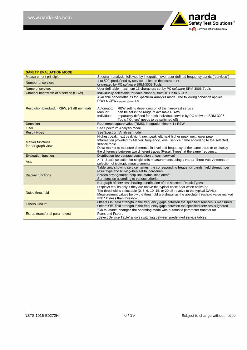
SAFETY EVALUATION MODE
Measurement principle Spectrum analysis, followed by integration over user-defined frequency bands (“services”)
Number of services 1 to 500, predefined by service tables on the instrument or created by PC software SRM-3006 Tools
Name of services User definable, maximum 15 characters set by PC software SRM-3006 Tools
Channel bandwidth of a service (CBW) Individually selectable for each channel, from 40 Hz to 6 GHz
Resolution bandwidth RBW, (-3 dB nominal)
Available bandwidths as for Spectrum Analysis mode. The following condition applies: RBW ≤ CBW(narrowest service) / 4 Automatic: RBW setting depending on of the narrowest service Manual: can be set in the range of available RBWs Individual: separately defined for each individual service by PC software SRM-3006
Tools (“Others” needs to be switched off)
Detection Root mean square value (RMS), integration time = 1 / RBW
Filter See Spectrum Analysis mode
Result types See Spectrum Analysis mode
Marker functions for bar graph view
Highest peak, next peak right, next peak left, next higher peak, next lower peak Information provided by Marker: frequency, level, service name according to the selected service table. Delta marker to measure difference in level and frequency of the same trace or to display the difference between two different traces (Result Types) at the same frequency.
Evaluation function Distribution (percentage contribution of each service)
Axis X, Y, Z axis selection for single-axis measurements using a Narda Three-Axis Antenna or selection of isotropic measurements
Display functions
Table view showing service names, the corresponding frequency bands, field strength per result type and RBW (when set to individual) Screen arrangement: help line, status lines on/off Sort function according to various criteria
Bar graph of services showing contribution of the selected Result Types
Noise threshold
Displays results only if they are above the typical noise floor when activated. The threshold is selectable (0, 3, 6, 10, 15, or 20 dB relative to the typical DANL). Measurement values below the threshold are shown as the absolute threshold value marked with “<” (less than threshold)
Others On/Off Others On: field strength in the frequency gaps between the specified services is measured Others Off: field strength in the frequency gaps between the specified services is ignored
Extras (transfer of parameters) “Go to: mode“ changes the operating mode with automatic parameter transfer for Fcent and Fspan. „Select Service Table“ allows switching between predefined service tables
NSTS 1015-E0272H 7 / 19 Subject to change without notice
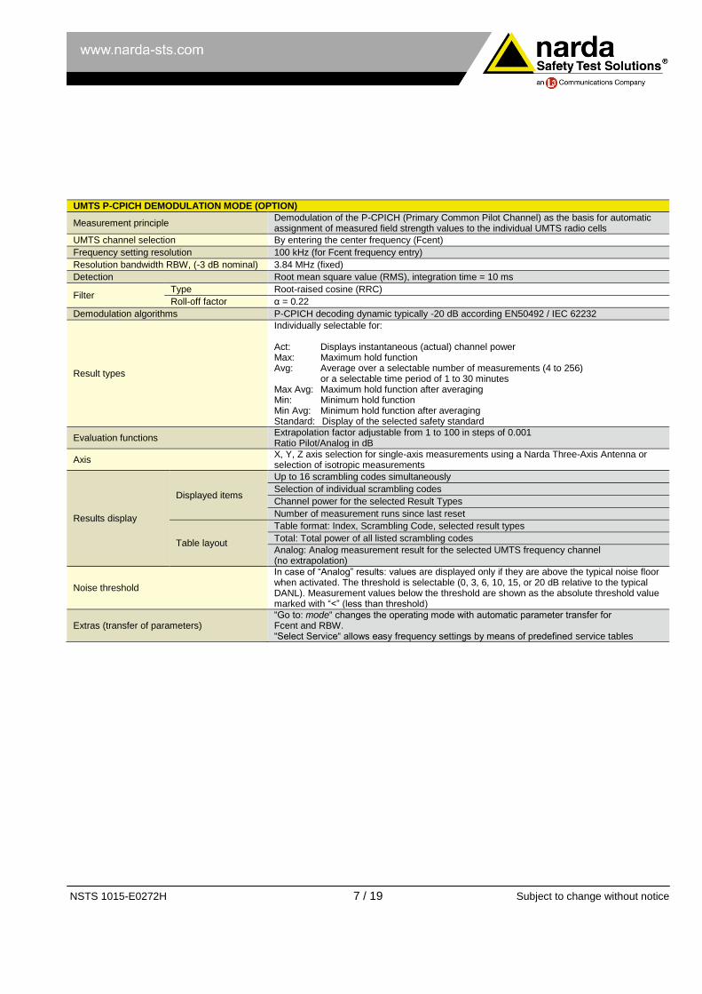
UMTS P-CPICH DEMODULATION MODE (OPTION)
Measurement principle Demodulation of the P-CPICH (Primary Common Pilot Channel) as the basis for automatic assignment of measured field strength values to the individual UMTS radio cells
UMTS channel selection By entering the center frequency (Fcent)
Frequency setting resolution 100 kHz (for Fcent frequency entry)
Resolution bandwidth RBW, (-3 dB nominal) 3.84 MHz (fixed)
Detection Root mean square value (RMS), integration time = 10 ms
Filter Type Root-raised cosine (RRC)
Roll-off factor α = 0.22
Demodulation algorithms P-CPICH decoding dynamic typically -20 dB according EN50492 / IEC 62232
Result types
Individually selectable for: Act: Displays instantaneous (actual) channel power Max: Maximum hold function Avg: Average over a selectable number of measurements (4 to 256) or a selectable time period of 1 to 30 minutes Max Avg: Maximum hold function after averaging Min: Minimum hold function Min Avg: Minimum hold function after averaging Standard: Display of the selected safety standard
Evaluation functions Extrapolation factor adjustable from 1 to 100 in steps of 0.001 Ratio Pilot/Analog in dB
Axis X, Y, Z axis selection for single-axis measurements using a Narda Three-Axis Antenna or selection of isotropic measurements
Results display
Displayed items
Up to 16 scrambling codes simultaneously
Selection of individual scrambling codes
Channel power for the selected Result Types
Number of measurement runs since last reset
Table layout
Table format: Index, Scrambling Code, selected result types
Total: Total power of all listed scrambling codes
Analog: Analog measurement result for the selected UMTS frequency channel (no extrapolation)
Noise threshold
In case of “Analog” results: values are displayed only if they are above the typical noise floor when activated. The threshold is selectable (0, 3, 6, 10, 15, or 20 dB relative to the typical DANL). Measurement values below the threshold are shown as the absolute threshold value marked with “<” (less than threshold)
Extras (transfer of parameters) “Go to: mode“ changes the operating mode with automatic parameter transfer for Fcent and RBW. “Select Service“ allows easy frequency settings by means of predefined service tables
NSTS 1015-E0272H 8 / 19 Subject to change without notice
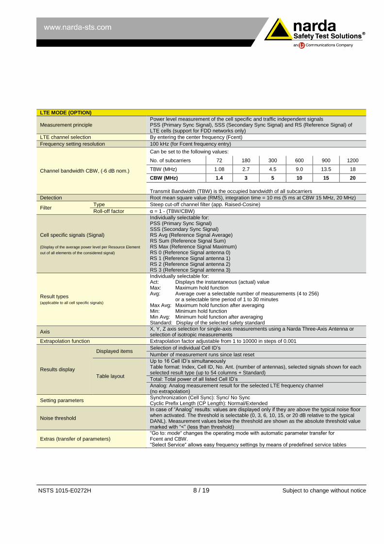
LTE MODE (OPTION)
Measurement principle Power level measurement of the cell specific and traffic independent signals PSS (Primary Sync Signal), SSS (Secondary Sync Signal) and RS (Reference Signal) of LTE cells (support for FDD networks only)
LTE channel selection By entering the center frequency (Fcent)
Frequency setting resolution 100 kHz (for Fcent frequency entry)
Channel bandwidth CBW, (-6 dB nom.)
Can be set to the following values:
No. of subcarriers 72 180 300 600 900 1200
TBW (MHz) 1.08 2.7 4.5 9.0 13.5 18
CBW (MHz) 1.4 3 5 10 15 20
Transmit Bandwidth (TBW) is the occupied bandwidth of all subcarriers
Detection Root mean square value (RMS), integration time = 10 ms (5 ms at CBW 15 MHz, 20 MHz)
Filter Type Steep cut-off channel filter (app. Raised-Cosine)
Roll-off factor α = 1 - (TBW/CBW)
Cell specific signals (Signal) (Display of the average power level per Resource Element
out of all elements of the considered signal)
Individually selectable for: PSS (Primary Sync Signal) SSS (Secondary Sync Signal) RS Avg (Reference Signal Average) RS Sum (Reference Signal Sum) RS Max (Reference Signal Maximum) RS 0 (Reference Signal antenna 0) RS 1 (Reference Signal antenna 1) RS 2 (Reference Signal antenna 2) RS 3 (Reference Signal antenna 3)
Result types (applicable to all cell specific signals)
Individually selectable for: Act: Displays the instantaneous (actual) value Max: Maximum hold function Avg: Average over a selectable number of measurements (4 to 256) or a selectable time period of 1 to 30 minutes Max Avg: Maximum hold function after averaging Min: Minimum hold function Min Avg: Minimum hold function after averaging Standard: Display of the selected safety standard
Axis X, Y, Z axis selection for single-axis measurements using a Narda Three-Axis Antenna or selection of isotropic measurements
Extrapolation function Extrapolation factor adjustable from 1 to 10000 in steps of 0.001
Results display
Displayed items Selection of individual Cell ID’s
Number of measurement runs since last reset
Table layout
Up to 16 Cell ID’s simultaneously Table format: Index, Cell ID, No. Ant. (number of antennas), selected signals shown for each selected result type (up to 54 columns + Standard)
Total: Total power of all listed Cell ID’s
Analog: Analog measurement result for the selected LTE frequency channel (no extrapolation)
Setting parameters Synchronization (Cell Sync): Sync/ No Sync Cyclic Prefix Length (CP Length): Normal/Extended
Noise threshold
In case of “Analog” results: values are displayed only if they are above the typical noise floor when activated. The threshold is selectable (0, 3, 6, 10, 15, or 20 dB relative to the typical DANL). Measurement values below the threshold are shown as the absolute threshold value marked with “<” (less than threshold)
Extras (transfer of parameters) “Go to: mode“ changes the operating mode with automatic parameter transfer for Fcent and CBW. “Select Service“ allows easy frequency settings by means of predefined service tables
NSTS 1015-E0272H 9 / 19 Subject to change without notice
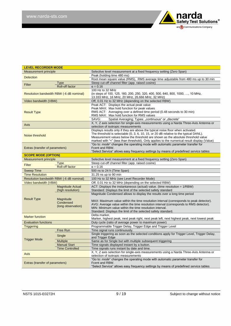
LEVEL RECORDER MODE Measurement principle Selective level measurement at a fixed frequency setting (Zero Span)
Detection Peak (holding time 480 ms)
Root mean square value (RMS), RMS average time adjustable from 480 ms up to 30 min
Filter Type Steep cut-off channel filter (app. raised cosine)
Roll-off factor α = 0.16
Resolution bandwidth RBW (-6 dB nominal) 100 Hz to 32 MHz (in steps of 100, 125, 160, 200, 250, 320, 400, 500, 640, 800, 1000, …, 10 MHz, 13.333 MHz, 16 MHz, 20 MHz, 26.666 MHz, 32 MHz)
Video bandwidth (VBW) Off, 0.01 Hz to 32 MHz (depending on the selected RBW)
Result Type
Peak ACT: Displays the actual peak value Peak MAX: Max hold function for peak values RMS ACT: Averaging over a defined time period (0.48 seconds to 30 min) RMS MAX: Max hold function for RMS values
SAVG: Spatial Averaging; Types: „continuous“ or „discrete“
Axis X, Y, Z axis selection for single-axis measurements using a Narda Three-Axis Antenna or selection of isotropic measurements
Noise threshold
Displays results only if they are above the typical noise floor when activated. The threshold is selectable (0, 3, 6, 10, 15, or 20 dB relative to the typical DANL). Measurement values below the threshold are shown as the absolute threshold value marked with “<” (less than threshold). Only applies to the numerical result display (Value)
Extras (transfer of parameters) “Go to: mode“ changes the operating mode with automatic parameter transfer for Fcent and RBW. “Select Service“ allows easy frequency settings by means of predefined service tables
SCOPE MODE (OPTION) Measurement principle Selective level measurement at a fixed frequency setting (Zero Span)
Filter Type Steep cut-off channel filter (app. raised cosine)
Roll-off factor α = 0.16
Sweep Time 500 ns to 24 h (Time Span)
Time Resolution 31.25 ns up to 90 min
Resolution bandwidth RBW (-6 dB nominal) 100 Hz to 32 MHz (see Level Recorder Mode)
Video bandwidth (VBW) Off, 0.01 Hz to 32 MHz (depending on the selected RBW)
Result Type
Magnitude Actual (high resolution)
ACT: Displays the instantaneous (actual) value. (time resolution = 1/RBW) Standard: Displays the limit of the selected safety standard
Magnitude Condensed (long observation)
Magnitude Condensed allows to display the results over a long time period MAX: Maximum value within the time resolution interval (corresponds to peak detector). AVG: Average value within the time resolution interval (corresponds to RMS detector). MIN: Minimum value within the time resolution interval. Standard: Displays the limit of the selected safety standard.
Marker function Delta marker, Marker, highest peak, next peak right, next peak left, next highest peak, next lowest peak
Evaluation functions Duty cycle (ratio of average power to maximum power)
Triggering Programmable Trigger Delay, Trigger Edge and Trigger Level
Trigger Mode
Free Run Time signal runs continuously.
Single Single triggering as soon as the selected conditions apply for Trigger Level, Trigger Delay, and Trigger Edge
Multiple Same as for Single but with multiple subsequent triggering
Manual Start Time signals displayed instant by a button.
Time Controlled Time signals runs instant by date and time.
Axis X, Y, Z axis selection for single-axis measurements using a Narda Three-Axis Antenna or selection of isotropic measurements
Extras (transfer of parameters) “Go to: mode“ changes the operating mode with automatic parameter transfer for Fcent and RBW. “Select Service“ allows easy frequency settings by means of predefined service tables

NSTS 1015-E0272H 10 / 19 Subject to change without notice
MEASUREMENT FUNCTIONS
Detection of Narda measurement antennas Automatic consideration of antenna parameters after antenna is plugged in: antenna type, serial number, calibration date and antenna factors (see below). Automatic frequency range adjustment according to the connected antenna
Antenna factors
Used to display measurement results in field strength units Stored in all Narda antennas during calibration Antenna factor lists for antennas from other manufacturers can be created and transferred to the instrument using the PC software SRM-3006 Tools/TS
Detection of Narda Cables Automatic consideration of cable parameters after cable is plugged in: Cable type, serial number, calibration date and loss factors (see below) Automatic frequency range adjustment according to the connected cable
Cable loss factors
Used for frequency response compensation of the power level display Stored in all Narda cables during calibration Cable loss lists for cables from other manufacturers can be created and transferred to the instrument using the PC software SRM-3006 Tools/TS
Units With antenna:
% (of the standard), V/m, A/m, W/m², mW/cm², dBV/m, dBmV/m, dBA/m, dBµV/m, dBm, dBV, dBmV, dBµV
Without antenna: dBm, dBV, dBmV, dBµV
Isotropic Measurements
Automatic switching of the antenna axes when using one of Narda’s three-axis measurement antennas followed by computation of the isotropic result. Support for sequential measurements using single-axis antennas with subsequent computation of the isotropic result. Both results are directly displayed as a spectrum curve or as numerical values
Weighted Display In % of standard for human safety standards like ICNIRP, IEEE, FCC etc. New lists of exposure limits can be created and transferred to the instrument using the PC software SRM-3006 Tools/TS
Correlation of results with telecom services
Service Tables specify the used frequency band, the name and the required resolution bandwidth (RBW) of up to 500 individual services in a single list. Thus measurement results can be easily assigned to a service even without the knowledge of the frequency (marker functions, peak table evaluation function, Safety Evaluation mode). Service Tables can be created either directly on the instrument or conveniently created and transferred to the instrument using the PC software SRM-3006 Tools/TS
Setups
Complete device configurations provide fast switching between different measurement tasks. Saved setups can be downloaded to a PC for archiving and uploaded back to the instrument using the PC software SRM-3006 Tools/TS
Measurement Routines Automated sequences of setups (created using the PC software SRM-3006 Tools/TS)
Results Memory
Memory modes
Result stored as: Spectrum in Spectrum Analysis mode(SPECTRUM), Table in Safety Evaluation mode (SAFETY), Values in UMTS P-CPICH Demodulation mode (UMTS) as well as for LTE mode (LTE) Values for Level Recorder (LEVEL) and Scope (SCOPE)
Conditional Storing Conditional storing of results exceeding a specified threshold value (in all operating modes except “Scope”) with individual storage rates and reset function
Time Controlled Storing Long term monitoring up to 99 hours (in all operating modes except “Scope”). Settings for: start date, start time, duration and time interval (6 s to 60 min)
Memory capacity 128 MB (up to 8000 spectra, 4000 screen shots)
Hold Button that “Freezes” the display; the measurement continues in the background.
Operating language Selectable: English (Default), French, Spanish, Turkish, Simplified Chinese
NSTS 1015-E0272H 11 / 19 Subject to change without notice
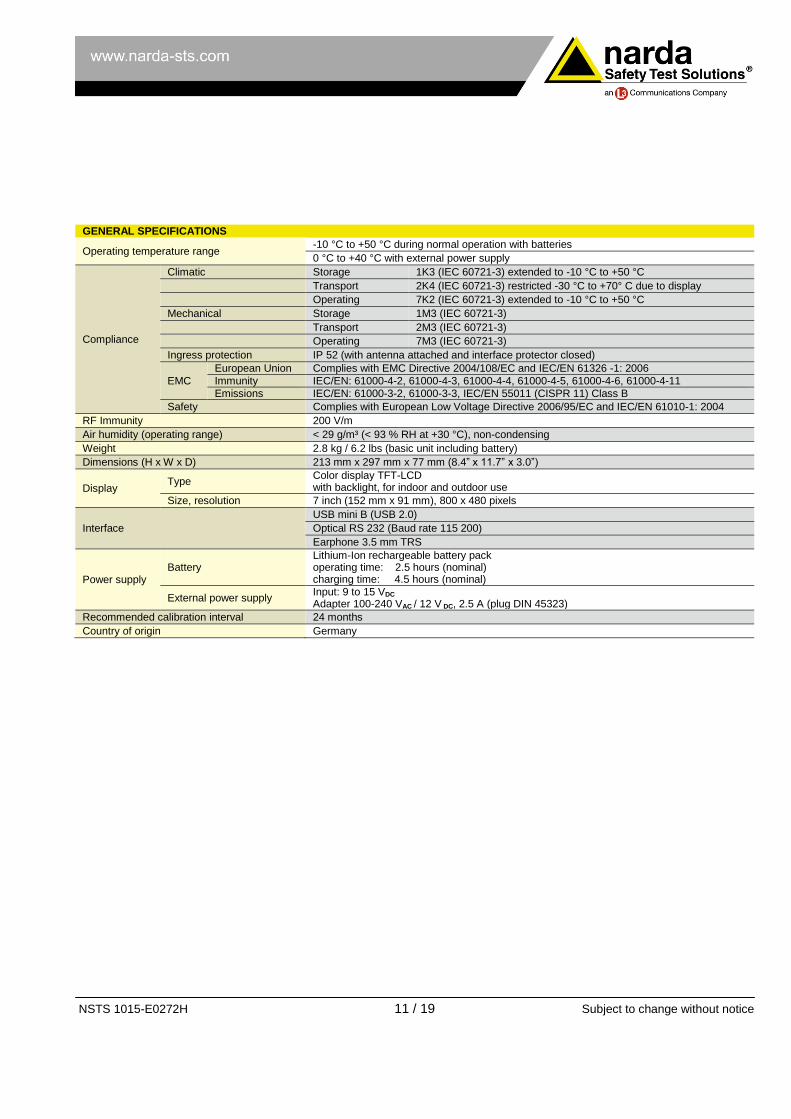
GENERAL SPECIFICATIONS
Operating temperature range -10 °C to +50 °C during normal operation with batteries
0 °C to +40 °C with external power supply
Compliance
Climatic Storage 1K3 (IEC 60721-3) extended to -10 °C to +50 °C
Transport 2K4 (IEC 60721-3) restricted -30 °C to +70° C due to display
Operating 7K2 (IEC 60721-3) extended to -10 °C to +50 °C
Mechanical Storage 1M3 (IEC 60721-3)
Transport 2M3 (IEC 60721-3)
Operating 7M3 (IEC 60721-3)
Ingress protection IP 52 (with antenna attached and interface protector closed)
EMC
European Union Complies with EMC Directive 2004/108/EC and IEC/EN 61326 -1: 2006
Immunity IEC/EN: 61000-4-2, 61000-4-3, 61000-4-4, 61000-4-5, 61000-4-6, 61000-4-11
Emissions IEC/EN: 61000-3-2, 61000-3-3, IEC/EN 55011 (CISPR 11) Class B
Safety Complies with European Low Voltage Directive 2006/95/EC and IEC/EN 61010-1: 2004
RF Immunity 200 V/m
Air humidity (operating range) < 29 g/m³ (< 93 % RH at +30 °C), non-condensing
Weight 2.8 kg / 6.2 lbs (basic unit including battery)
Dimensions (H x W x D) 213 mm x 297 mm x 77 mm (8.4” x 11.7” x 3.0”)
Display Type
Color display TFT-LCD with backlight, for indoor and outdoor use
Size, resolution 7 inch (152 mm x 91 mm), 800 x 480 pixels
Interface
USB mini B (USB 2.0)
Optical RS 232 (Baud rate 115 200)
Earphone 3.5 mm TRS
Power supply Battery
Lithium-Ion rechargeable battery pack operating time: 2.5 hours (nominal) charging time: 4.5 hours (nominal)
External power supply Input: 9 to 15 VDC Adapter 100-240 VAC / 12 V DC, 2.5 A (plug DIN 45323)
Recommended calibration interval 24 months
Country of origin Germany

NSTS 1015-E0272H 12 / 19 Subject to change without notice
SPECIFICATIONS ISOTROPIC ANTENNAS Three-axis antenna (E-Field) 3501/03
Frequency range
27 MHz to 3 GHz The correction factors determined individually during calibration are stored in an EEPROM and are applied automatically when used in conjunction with the SRM basic unit.
Antenna type E-field
Sensor type Three-axis design with scanned axes
Dynamic range a) 0.2 mV/m to 200 V/m (typ.)
Maximum field strength (destruction limit) 435 V/m or 50 mW/cm² (nom.)
Displayed Average Noise Level (DANL) in conjunction with the SRM basic unit
Frequency range Single-axis measurement with isotropic antenna
Isotropic measurement
900 MHz (RBW = 1 kHz) 25 µV/m (typ.) 40 µV/m (typ.)
2.1 GHz (RBW = 1 kHz) 40 µV/m (typ.) 70 µV/m (typ.)
Measurement range limit (for single CW signal)
300 V/m (typ.) 1000 V/m (typ.) for f ≤ 110 MHz
RF connector
N-Connector, 50 Ω, male
MEASUREMENT UNCERTAINTY
Expanded measurement uncertainty b)
(in conjunction with SRM basic unit and 1.5 m RF cable)
Frequency range Single-axis measurement with isotropic antenna
Isotropic measurement
27 – 85 MHz +2.4 / -3.3 dB + 3.2 / -4.7 dB
> 85–900 MHz +2.4 / -3.4 dB +2.5 / -3.6 dB
> 900-1400 MHz +2.3 / -3.1 dB +2.5 / -3.4 dB
> 1400-1600 MHz +2.3 / -3.1 dB +2.6 / -3.8 dB
> 1600-1800 MHz +1.8 / -2.3 dB +2.2 / -3.0 dB
> 1800-2200 MHz +1.8 / -2.3 dB +2.4 / -3.3 dB
> 2200-2700 MHz +1.9 / -2.4 dB +2.7 / -3.8 dB
> 2700-3000 MHz +1.9 / -2.4 dB +3.3 / -5.3 dB
GENERAL SPECIFICATIONS
Operating temperature range -10 °C to +50 °C (same as SRM basic unit)
Compliance
Climatic Storage 1K3 (IEC 60721-3) extended to -10 °C to +50 °C
Transport 2K4 (IEC 60721-3) -40 °C to +70 °C
Operating 7K2 (IEC 60721-3) extended to -10 °C to +50 °C
Mechanical Storage 1M3 (IEC 60721-3)
Transport 2M3 (IEC 60721-3)
Operating 7M3 (IEC 60721-3)
Ingress protection IP 52 (antenna connected)
EMC
European Union Complies with EMC Directive 2004/108/EC and IEC/EN 61326 -1: 2006
Immunity IEC/EN: 61000-4-2, 61000-4-3, 61000-4-4, 61000-4-5, 61000-4-6, 61000-4-11
Emissions IEC/EN: 61000-3-2, 61000-3-3, IEC/EN 55011 (CISPR 11) Class B
Safety Complies with European Low Voltage Directive 2006/95/EC and IEC/EN 61010-1: 2004
Air humidity (operating range) < 29 g/m³ (< 93 % RH at +30 °C), non-condensing
Weight 450 g
Dimensions 450 mm length; 120 mm antenna head diameter
Calibration 20 reference points: (26; 45; 75; 100; 200; 300; 433; 600; 750; 900) MHz (1; 1.2; 1.4; 1.6; 1.8; 2; 2.2; 2.45; 2.7; 3) GHz The SRM basic unit applies linear interpolation between reference points
Recommended calibration interval 24 months
Country of origin Germany a) For a signal to noise ratio of 10 dB (RBW = 1 kHz); 800 MHz to 1.8 GHz
b) Valid for the temperature range +15 °C to +30 °C, according to the definition on page 3
NSTS 1015-E0272H 13 / 19 Subject to change without notice
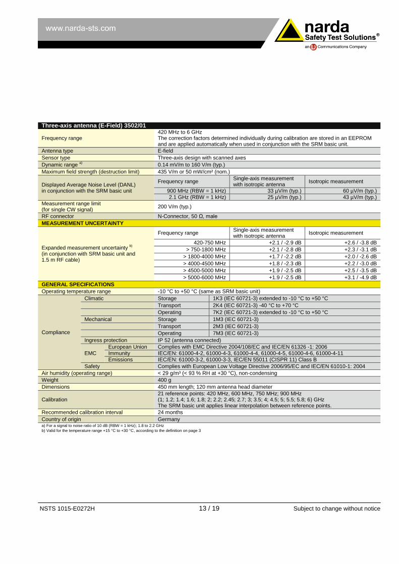
Three-axis antenna (E-Field) 3502/01
Frequency range
420 MHz to 6 GHz The correction factors determined individually during calibration are stored in an EEPROM and are applied automatically when used in conjunction with the SRM basic unit.
Antenna type E-field
Sensor type Three-axis design with scanned axes
Dynamic range a) 0.14 mV/m to 160 V/m (typ.)
Maximum field strength (destruction limit) 435 V/m or 50 mW/cm² (nom.)
Displayed Average Noise Level (DANL) in conjunction with the SRM basic unit
Frequency range Single-axis measurement with isotropic antenna
Isotropic measurement
900 MHz (RBW = 1 kHz) 33 µV/m (typ.) 60 µV/m (typ.)
2.1 GHz (RBW = 1 kHz) 25 µV/m (typ.) 43 µV/m (typ.)
Measurement range limit (for single CW signal)
200 V/m (typ.)
RF connector
N-Connector, 50 Ω, male
MEASUREMENT UNCERTAINTY
Expanded measurement uncertainty b)
(in conjunction with SRM basic unit and 1.5 m RF cable)
Frequency range Single-axis measurement with isotropic antenna
Isotropic measurement
420-750 MHz +2.1 / -2.9 dB +2.6 / -3.8 dB
> 750-1800 MHz +2.1 / -2.8 dB +2.3 / -3.1 dB
> 1800-4000 MHz +1.7 / -2.2 dB +2.0 / -2.6 dB
> 4000-4500 MHz +1.8 / -2.3 dB +2.2 / -3.0 dB
> 4500-5000 MHz +1.9 / -2.5 dB +2.5 / -3.5 dB
> 5000-6000 MHz +1.9 / -2.5 dB +3.1 / -4.9 dB
GENERAL SPECIFICATIONS
Operating temperature range -10 °C to +50 °C (same as SRM basic unit)
Compliance
Climatic Storage 1K3 (IEC 60721-3) extended to -10 °C to +50 °C
Transport 2K4 (IEC 60721-3) -40 °C to +70 °C
Operating 7K2 (IEC 60721-3) extended to -10 °C to +50 °C
Mechanical Storage 1M3 (IEC 60721-3)
Transport 2M3 (IEC 60721-3)
Operating 7M3 (IEC 60721-3)
Ingress protection IP 52 (antenna connected)
EMC
European Union Complies with EMC Directive 2004/108/EC and IEC/EN 61326 -1: 2006
Immunity IEC/EN: 61000-4-2, 61000-4-3, 61000-4-4, 61000-4-5, 61000-4-6, 61000-4-11
Emissions IEC/EN: 61000-3-2, 61000-3-3, IEC/EN 55011 (CISPR 11) Class B
Safety Complies with European Low Voltage Directive 2006/95/EC and IEC/EN 61010-1: 2004
Air humidity (operating range) < 29 g/m³ (< 93 % RH at +30 °C), non-condensing
Weight 400 g
Dimensions 450 mm length; 120 mm antenna head diameter
Calibration 21 reference points: 420 MHz, 600 MHz, 750 MHz; 900 MHz (1; 1.2; 1.4; 1.6; 1.8; 2; 2.2; 2.45; 2.7; 3; 3.5; 4; 4.5; 5; 5.5; 5.8; 6) GHz The SRM basic unit applies linear interpolation between reference points.
Recommended calibration interval 24 months
Country of origin Germany a) For a signal to noise ratio of 10 dB (RBW = 1 kHz); 1.8 to 2.2 GHz
b) Valid for the temperature range +15 °C to +30 °C, according to the definition on page 3
NSTS 1015-E0272H 14 / 19 Subject to change without notice
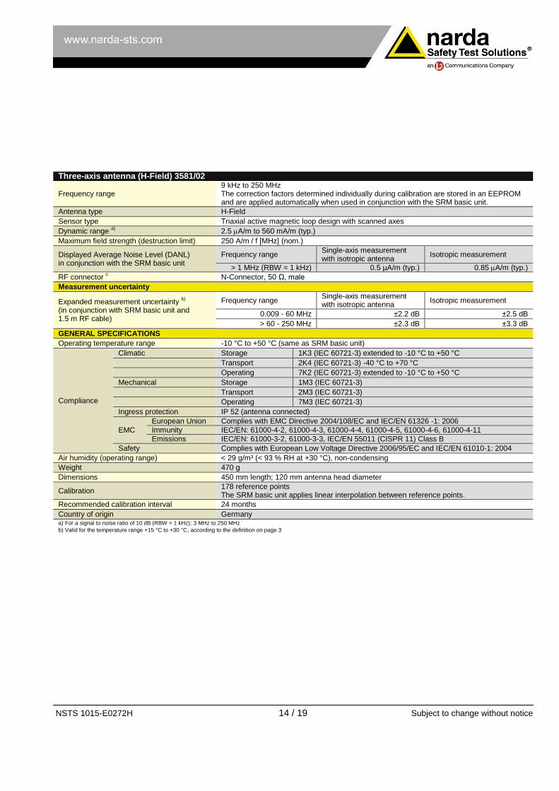
Three-axis antenna (H-Field) 3581/02
Frequency range
9 kHz to 250 MHz The correction factors determined individually during calibration are stored in an EEPROM and are applied automatically when used in conjunction with the SRM basic unit.
Antenna type H-Field
Sensor type Triaxial active magnetic loop design with scanned axes
Dynamic range a) 2.5 A/m to 560 mA/m (typ.)
Maximum field strength (destruction limit) 250 A/m / f [MHz] (nom.)
Displayed Average Noise Level (DANL) in conjunction with the SRM basic unit
Frequency range Single-axis measurement with isotropic antenna
Isotropic measurement
> 1 MHz (RBW = 1 kHz) 0.5 µA/m (typ.) 0.85 A/m (typ.)
RF connector c
N-Connector, 50 Ω, male
Measurement uncertainty
Expanded measurement uncertainty b)
(in conjunction with SRM basic unit and 1.5 m RF cable)
Frequency range Single-axis measurement with isotropic antenna
Isotropic measurement
0.009 - 60 MHz ±2.2 dB ±2.5 dB
> 60 - 250 MHz ±2.3 dB ±3.3 dB
GENERAL SPECIFICATIONS
Operating temperature range -10 °C to +50 °C (same as SRM basic unit)
Compliance
Climatic Storage 1K3 (IEC 60721-3) extended to -10 °C to +50 °C
Transport 2K4 (IEC 60721-3) -40 °C to +70 °C
Operating 7K2 (IEC 60721-3) extended to -10 °C to +50 °C
Mechanical Storage 1M3 (IEC 60721-3)
Transport 2M3 (IEC 60721-3)
Operating 7M3 (IEC 60721-3)
Ingress protection IP 52 (antenna connected)
EMC
European Union Complies with EMC Directive 2004/108/EC and IEC/EN 61326 -1: 2006
Immunity IEC/EN: 61000-4-2, 61000-4-3, 61000-4-4, 61000-4-5, 61000-4-6, 61000-4-11
Emissions IEC/EN: 61000-3-2, 61000-3-3, IEC/EN 55011 (CISPR 11) Class B
Safety Complies with European Low Voltage Directive 2006/95/EC and IEC/EN 61010-1: 2004
Air humidity (operating range) < 29 g/m³ (< 93 % RH at +30 °C), non-condensing
Weight 470 g
Dimensions 450 mm length; 120 mm antenna head diameter
Calibration 178 reference points The SRM basic unit applies linear interpolation between reference points.
Recommended calibration interval 24 months
Country of origin Germany a) For a signal to noise ratio of 10 dB (RBW = 1 kHz); 3 MHz to 250 MHz
b) Valid for the temperature range +15 °C to +30 °C, according to the definition on page 3

NSTS 1015-E0272H 15 / 19 Subject to change without notice
SPECIFICATIONS SINGLE-AXIS ANTENNAS Single-axis antenna (E-field) 3531 / 01
Frequency range 27 MHz to 3 GHz The correction factors determined individually during calibration are stored in an EEPROM and are applied automatically when used in conjunction with the SRM basic unit.
Antenna type E-Field
Sensor type Single-axis passive wide band dipole
Dynamic range a) 60 µV/m to 80 V/m (typ.)
Maximum field strength (destruction limit) > 300 V/m or 25 mW/cm² (nom.)
Displayed Average Noise Level (DANL) in conjunction with the SRM basic unit
20 µV/m (typ.) from 100 MHz to 2.2 GHz with RBW = 1 kHz
Measurement range limit (for single CW signal)
160 V/m (typ.)
RF connector N-Connector, 50 Ω, male
UNCERTAINTY
Expanded measurement uncertainty b)
(in conjunction with SRM basic unit and 1.5 m RF cable)
Frequency range Single-axis measurement
26 - 300 MHz ±2.1 dB
> 301 - 433 MHz ±2.4 dB
> 434 - 1600 MHz ±2.2 dB
> 1601 - 3000 MHz ±1.9 dB
GENERAL SPECIFICATIONS
Operating temperature range -10 °C to 50 °C (same as SRM basic unit)
Compliance
Climatic Storage 1K3 (IEC 60721-3) extended to -10 °C to +50 °C
Transport 2K4 (IEC 60721-3) -40 °C to +70 °C
Operating 7K2 (IEC 60721-3) extended to -10 °C to +50 °C
Mechanical Storage 1M3 (IEC 60721-3)
Transport 2M3 (IEC 60721-3)
Operating 7M3 (IEC 60721-3)
Ingress protection IP 52 (antenna connected)
EMC
European Union Complies with EMC Directive 2004/108/EC and IEC/EN 61326 -1: 2006
Immunity IEC/EN: 61000-4-2, 61000-4-3, 61000-4-4, 61000-4-5, 61000-4-6, 61000-4-11
Emissions IEC/EN: 61000-3-2, 61000-3-3, IEC/EN 55011 (CISPR 11) Class B
Safety Complies with European Low Voltage Directive 2006/95/EC and IEC/EN 61010-1: 2004
Air humidity (operating range) < 29 g/m³ (< 93 % RH at +30 °C), non-condensing
Weight 450 g
Dimensions 460 mm length; 135 mm x 90 mm antenna head dimensions
Calibration
24 reference points (26, 30, 40, 50, 60, 75, 100, 200, 300, 433, 600, 750, 900) MHz (1, 1.2, 1.4, 1.6, 1.8, 2, 2.2, 2.45, 2.6, 2.8 , 3) GHz The SRM applies linear interpolation between reference points.
Recommended calibration interval 24 months
Country of origin Germany
a) For a signal to noise ratio of 10 dB (RBW = 1 kHz); 100 MHz to 2.2 GHz
b) Valid for the temperature range +15 °C to +30 °C, according to the definition on page 3

NSTS 1015-E0272H 16 / 19 Subject to change without notice
Single-axis antenna (E-field) 3531/04
Frequency range 9 kHz to 300 MHz The correction factors determined individually during calibration are stored in an EEPROM and are applied automatically when used in conjunction with the SRM basic unit.
Antenna type E-field
Sensor type Single-axis active broadband dipole
Dynamic range a)
50 µV/m to 16 V/m (typ.) for 300 kHz to 10 MHz 50 µV/m to 36 V/m (typ.) for > 10 MHz to 300 MHz
Maximum field strength (destruction limit) > 1000 V/m (nom.)
Displayed Average Noise Level (DANL) in conjunction with the SRM basic unit
20 µV/m (typ.) for each frequency > 1 MHz with RBW = 1 kHz
Measurement range limit (for single CW signal)
50 V/m (typ.)
RF connector N-Connector, 50 Ω, male
UNCERTAINTY
Expanded measurement uncertainty b)
(in conjunction with SRM basic unit and 1.5 m cable)
Frequency range Single-axis measurement
0.009 - 300 MHz ±2.0 dB
GENERAL SPECIFICATIONS
Operating temperature range -10 °C to 50 °C (same as SRM basic unit)
Compliance
Climatic Storage 1K3 (IEC 60721-3) extended to -10 °C to +50 °C
Transport 2K4 (IEC 60721-3) -40 °C to +70 °C
Operating 7K2 (IEC 60721-3) extended to -10 °C to +50 °C
Mechanical Storage 1M3 (IEC 60721-3)
Transport 2M3 (IEC 60721-3)
Operating 7M3 (IEC 60721-3)
Ingress protection IP 52 (antenna connected)
EMC
European Union Complies with EMC Directive 2004/108/EC and IEC/EN 61326 -1: 2006
Immunity IEC/EN: 61000-4-2, 61000-4-3, 61000-4-4, 61000-4-5, 61000-4-6, 61000-4-11
Emissions IEC/EN: 61000-3-2, 61000-3-3, IEC/EN 55011 (CISPR 11) Class B
Safety Complies with European Low Voltage Directive 2006/95/EC and IEC/EN 61010-1: 2004
Air humidity (operating range) < 29 g/m³ (< 93 % RH at +30 °C), non-condensing
Weight 550 g
Dimensions 460 mm length; 135 mm x 90 mm antenna head dimension
Calibration 183 reference points The SRM applies linear interpolation between reference points.
Recommended calibration interval 24 months
Country of origin Germany a) For a signal to noise ratio of 10 dB (RBW = 1 kHz)
b) Valid for the temperature range +15 °C to +30 °C, according to the definition on page 3
NSTS 1015-E0272H 17 / 19 Subject to change without notice
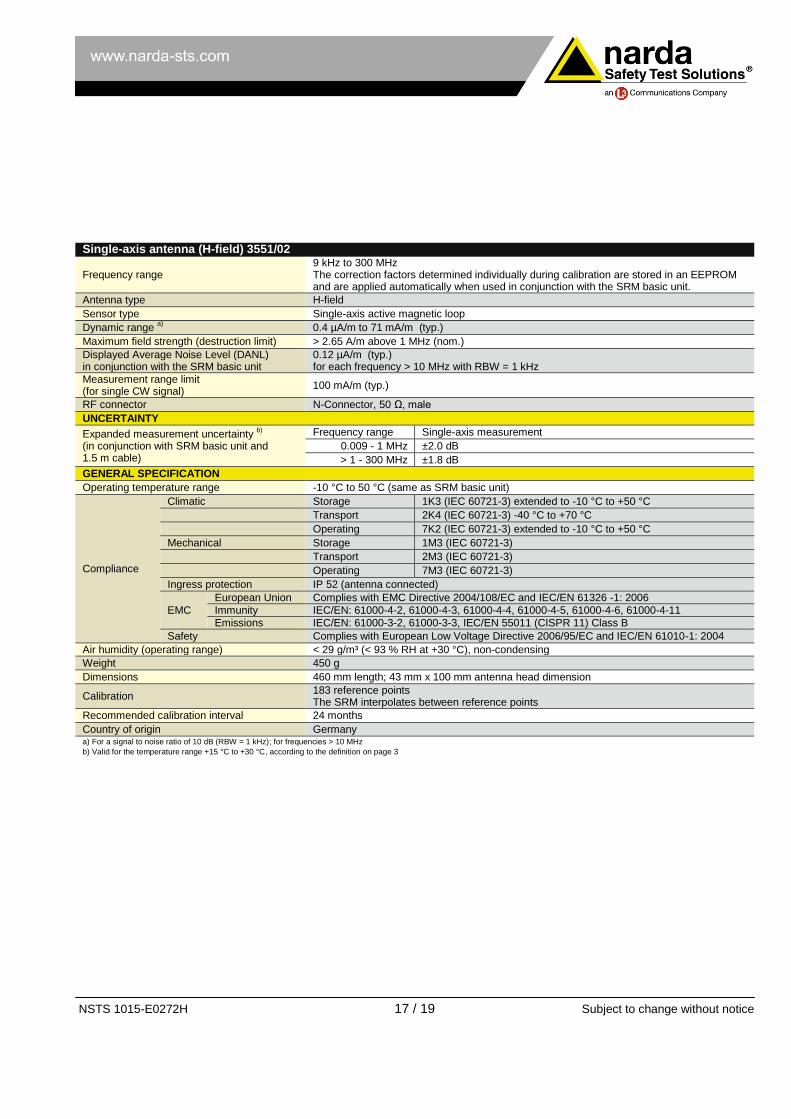
Single-axis antenna (H-field) 3551/02
Frequency range 9 kHz to 300 MHz The correction factors determined individually during calibration are stored in an EEPROM and are applied automatically when used in conjunction with the SRM basic unit.
Antenna type H-field
Sensor type Single-axis active magnetic loop
Dynamic range a) 0.4 µA/m to 71 mA/m (typ.)
Maximum field strength (destruction limit) > 2.65 A/m above 1 MHz (nom.)
Displayed Average Noise Level (DANL) in conjunction with the SRM basic unit
0.12 µA/m (typ.) for each frequency > 10 MHz with RBW = 1 kHz
Measurement range limit (for single CW signal)
100 mA/m (typ.)
RF connector N-Connector, 50 Ω, male
UNCERTAINTY
Expanded measurement uncertainty b)
(in conjunction with SRM basic unit and 1.5 m cable)
Frequency range Single-axis measurement
0.009 - 1 MHz ±2.0 dB
> 1 - 300 MHz ±1.8 dB
GENERAL SPECIFICATION
Operating temperature range -10 °C to 50 °C (same as SRM basic unit)
Compliance
Climatic Storage 1K3 (IEC 60721-3) extended to -10 °C to +50 °C
Transport 2K4 (IEC 60721-3) -40 °C to +70 °C
Operating 7K2 (IEC 60721-3) extended to -10 °C to +50 °C
Mechanical Storage 1M3 (IEC 60721-3)
Transport 2M3 (IEC 60721-3)
Operating 7M3 (IEC 60721-3)
Ingress protection IP 52 (antenna connected)
EMC
European Union Complies with EMC Directive 2004/108/EC and IEC/EN 61326 -1: 2006
Immunity IEC/EN: 61000-4-2, 61000-4-3, 61000-4-4, 61000-4-5, 61000-4-6, 61000-4-11
Emissions IEC/EN: 61000-3-2, 61000-3-3, IEC/EN 55011 (CISPR 11) Class B
Safety Complies with European Low Voltage Directive 2006/95/EC and IEC/EN 61010-1: 2004
Air humidity (operating range) < 29 g/m³ (< 93 % RH at +30 °C), non-condensing
Weight 450 g
Dimensions 460 mm length; 43 mm x 100 mm antenna head dimension
Calibration 183 reference points The SRM interpolates between reference points
Recommended calibration interval 24 months
Country of origin Germany a) For a signal to noise ratio of 10 dB (RBW = 1 kHz); for frequencies > 10 MHz
b) Valid for the temperature range +15 °C to +30 °C, according to the definition on page 3

NSTS 1015-E0272H 18 / 19 Subject to change without notice
ORDERING INFORMATION INSTRUMENT SETS
SRM – Set Overview Part Number
SRM-3006, Selective Radiation Meter, Set 1/2, Basic Unit, no Antenna Set includes:
- Selective Radiation Meter, Basic Unit, SRM-3006 - RF-Cable SRM, 9kHz-6GHz, N 50 Ohm, 1.5m (3602/01) - Carrying Strap for SRM (Basic Unit) (3001/90.02) - Holding Strap for SRM-3006 Basic Unit (3001/90.12) - Operating Manual SRM-3006, English - Power Supply 12VDC, 100V-240VAC, all Plugs (2259/92.04) - Software, SRM-3006 Tools (3006/93.01) - Cable, USB 2.0, Master/Slave - A/B mini (2260/90.55)
Set with Hardcase 3006/101 Set with Softcase 3006/102
SRM-3006, Selective Radiation Meter, Set 3/4, Basic Unit plus one Isotropic Antenna (420MHz-6GHz) Set includes:
- Selective Radiation Meter, Basic Unit, SRM-3006 - Antenna, Three-Axis, E-Field, 420 MHz-6GHz (3502/01) - RF-Cable SRM, 9kHz-6GHz, N 50 Ohm, 1.5m (3602/01) - Carrying Strap for SRM (Basic Unit) (3001/90.02) - Holding Strap for SRM-3006 Basic Unit (3001/90.12) - Operating Manual SRM-3006, English - Power Supply 12VDC, 100V-240VAC, all Plugs (2259/92.04) - Software, SRM-3006 Tools (3006/93.01) - Cable, USB 2.0, Master/Slave - A/B mini (2260/90.55)
Set with Hardcase 3006/103 Set with Softcase 3006/104
SRM-3006, Selective Radiation Meter, Set 5/6, Basic Unit plus two Isotropic Antennas Set includes:
- Selective Radiation Meter, Basic Unit, SRM-3006 - Antenna, Three-Axis, E-Field, 420 MHz-6GHz (3502/01) - Antenna, Three-Axis, E-Field, 27 MHz-3GHz (3501/03) - RF-Cable SRM, 9kHz-6GHz, N 50 Ohm, 1.5m (3602/01) - Carrying Strap for SRM (Basic Unit) (3001/90.02) - Holding Strap for SRM-3006 Basic Unit (3001/90.12) - Operating Manual SRM-3006, English - Power Supply 12VDC, 100V-240VAC, all Plugs (2259/92.04) - Software, SRM-3006 Tools (3006/93.01) - Cable, USB 2.0, Master/Slave - A/B mini (2260/90.55)
Set with Hardcase 3006/105 Set with Softcase 3006/106
SRM-3006, Selective Radiation Meter, Set 7/8, Basic Unit plus one Isotropic Antenna (27MHz-3GHz) Set includes:
- Selective Radiation Meter, Basic Unit, SRM-3006 - Antenna, Three-Axis, E-Field, 27MHz-3GHz (3501/03) - RF-Cable SRM, 9kHz-6GHz, N 50 Ohm, 1.5m (3602/01) - Carrying Strap for SRM (Basic Unit) (3001/90.02) - Holding Strap for SRM-3006 Basic Unit (3001/90.12) - Operating Manual SRM-3006, English - Power Supply 12VDC, 100V-240VAC, all Plugs (2259/92.04) - Software, SRM-3006 Tools (3006/93.01) - Cable, USB 2.0, Master/Slave - A/B mini (2260/90.55)
Set with Hardcase 3006/107 Set with Softcase 3006/108
NSTS 1015-E0272H 19 / 19 Subject to change without notice
® Names and Logo are registered trademarks of Narda Safety Test Solutions GmbH and L3 Communications Holdings, Inc. – Trade names are trademarks of the owners.
Narda Safety Test Solutions GmbH
Sandwiesenstraße 7
72793 Pfullingen, Germany
Tel. +49 7121 97 32 0
Fax +49 7121 97 32 790
www.narda-sts.com
Narda Safety Test Solutions
435 Moreland Road
Hauppauge, NY 11788, USA
Phone +1 631 231-1700
Fax +1 631 231-1711
www.narda-sts.us
Narda Safety Test Solutions Srl
Via Leonardo da Vinci, 21/23
20090 Segrate (Milano), Italy
Phone +39 02 26 998 71
Fax +39 02 26 998 700
www.narda-sts.it
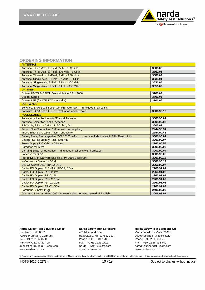
ORDERING INFORMATION ANTENNAS
Antenna, Three-Axis, E-Field, 27 MHz - 3 GHz 3501/03
Antenna, Three-Axis, E-Field, 420 MHz - 6 GHz 3502/01
Antenna, Three-Axis, H-Field, 9 kHz - 250 MHz 3581/02
Antenna, Single-Axis, E-Field, 27 MHz - 3 GHz 3531/01
Antenna, Single-Axis, E-Field, 9 kHz - 300 MHz 3531/04
Antenna, Single-Axis, H-Field, 9 kHz - 300 MHz 3551/02
OPTIONS
Option, UMTS P-CPICH Demodulation SRM-3006 3701/04
Option, Scope 3701/05
Option, LTE (for LTE FDD networks) 3701/06
SOFTWARE
Software, SRM-3006 Tools, Configuration SW (included in all sets) -
Software, SRM-3006 TS, PC Evaluation and Remote 3006/93.10
ACCESSORIES
Antenna Holder for Uniaxial/Triaxial Antenna 3501/90.01
Antenna Holder for Triaxial Antenna 3501/90.02
RF-Cable, 9 kHz – 6 GHz, N 50 ohm, 5m 3602/02
Tripod, Non-Conductive, 1.65 m with carrying bag 2244/90.31
Tripod Extension, 0.50m, Non-Conductive 2244/90.45
Battery Pack, Rechargeable, 7V4 / 5100 mAh (one is included in each SRM Basic Unit) 3001/90.01
Charger Set for Battery Pack, External 3001/90.07
Power Supply DC Vehicle Adapter 2260/90.56
Hardcase for SRM 3001/90.03
Carrying Strap for Hardcase (included in all sets with hardcase) 3001/90.04
Softcase for SRM 3001/90.05
Protective Soft Carrying Bag for SRM-3006 Basic Unit 3001/90.13
N-Connector Saver for SRM 3001/90.14
O/E Converter USB, RP-02/USB 2260/90.07
Cable, FO Duplex, F-SMA to RP-02, 0.3m 2260/91.01
Cable, FO Duplex, RP-02, 2m 2260/91.02
Cable, FO Duplex, RP-02, 5m 2260/91.09
Cable, FO Duplex, RP-02, 10m 2260/91.07
Cable, FO Duplex, RP-02, 20m 2260/91.03
Cable, FO Duplex, RP-02, 50m 2260/91.04
Earphone, 3.5mm Plug 2400/90.03
Operating Manual SRM-3006, German (select for free instead of English) 3006/98.01