Selective compositional mixing in GaAs/AlGaAs superlattice … · 2004-01-02 · Selective...
9
Selective compositional mixing in GaAs/AIGaAs superlattice induced by low dose Si focused ion beam implantation P. Chen and A. J. Steckla) Nanoelectronics L.aboratoory Department of Electrical and Computer Engineering, University of Cincinnati, Cincinnati, Ohio 45221-0030 -. (Received 26 August 1994; accepted for publication 6 February 1995) The Al-Ga interdiffusion induced by Si focused ion beam implantation and subsequent rapid thermal annealing (RTA) was investigated in an A1,,Gac7As/GaAs superlattice structure with equal 3.5 nm barrier and well widths. Si++ was accelerated to either 50 or 100 kV -and implanted parallel to sample normal at doses ranging from lOI to 10t5/cm2. The effect of rapid thermal anneal of 10 s at, 950 “C was characterized by the secondary ion mass spectrometry technique. In the implanted region, the interdiffusion causing compositional mixing was significantly enhanced by the Si implantation. An ion dose as low as 1 X 10’4/cm2 results in a two-order of magnitude increase in the interdiffusion coefficient, to a value of 4.5X lo-l4 cm2/s, producing a mixing effectiveness of -90%. In contrast, the RTA-only case produces an interdiffusion coefficient of 1.3X1O-‘6 cm2fs and very little mixing. A strong depth dependence of the mixing process was observed at 100 keV implantation energy, with a “pinch-off” (more heavily mixed) region being formed at a certain depth. It is noticed that the depth.where this enhancement occurred is not associated with either the maximum concentration of Si ions or of vacancies. Instead, it coincides with the positive maximum of the second derivative of the vacancy profile, which in turn represents a maxirnum in the vacancy injection generated by the presence of a transient vacancy concentration gradient. Based on these findings, a theoretical model was developed using vacancy injection as responsible for mixing. 0 1995 American Institute of Physics. I. INTRODUCTION It is known that the compositional intermixing of AlGaAs/GaAs superlattice structures can be significantly en- hanced by introducing certain species such as Si, Zn, Al, and Ga.’ The energy band gap and the index of refraction, as well as other material properties, are altered in the mixed region to correspond to an alloy of the appropriate composition. Using this effect, optical devices such as distributed Bragg reflector (DBR) and distributed feedback (DFB) lasers, chan- nel waveguides, quantum wires, and quantum dots can be fabricated by locally mixing the superlattice. Among the various approaches to implementing localized mixing, Si ion implantation in conjunction with subsequent thermal anneal- ing has been proven to be one of the most efficient methods for inducing mixing. Focused ion beam (FIB) implantation technology has been especially attractive in this application, since it provides a maskless process with high spatial resolution.2 Many applications of superlattice mixing demand highly sophisticated control in both horizontal and vertical direc- tions. Usually, minimal lateral spreading of the mixed region is required for implementation of fine features. For instance, a first order laser grating in the AlGaAs/GaAs material sys- tem requires a grating period of about 120 nm. Thus, the mixed region should not exceed 60 nm in width. Another example is quantum wires whose width is expected to be smaller than 20 nm. Therefore, the minimization of the lat- eral dimension of the mixed region is a serious consider- “)Author to whom correspondence should be addressed; Electronic mail: [email protected] ation. In general, the lateral resolution is limited by the pre- cision of the pattern generation and/or transfer technology, the lateral profiles of the ion beam (and of the ions implanted in the solid), and by diffusion during the post-implantation annealing. The precision of pattern generation and/or transfer technology relies on the capability of the equipment. With FIB technology, fairly high spatial resolution can be achieved. However, the ultimate resolution is greatly depen- dent on ion beam profile and processing conditions such as ion energy, dose, and thermal annealing. To obtain a high resolution pattern, a low dose is preferred because it results in a laterally narrower mixed region and it reduces the implantation-induced damage. Rapid thermal annealing is, frequently employed in order to minimize lateral diffusion, to preserve the sharpness of the heterointerface, and to sim- plify the process. Finally, a short period superlattice, which is more readily mixed, is advantageous for the same reasons. In addition to optimization in the lateral direction, depth control of the mixed region in the vertical direction is also critical for a number of applications, for instance the gain- coupled grating in a DFB laser. Hence, a thorough under- standing of the mixing mechanism is essential for precise control of the mixing process. The occurrence of AlGaAs/GaAs intermixing results from Ga-Al interdiffusion during the thermal process. The interdiffusion of column IlI atoms is known to proceed through point defects of the crystal. Therefore, the presence of extra vacancies will enhance the interdiffusion and, in turn, the intermixing. Furthermore, as charged point defects are introduced via doping, the interdiffusion will be further enhanced due to the interaction between impurities and charged point defects. Under conditions of thermal equilib- 5616 J. Appl. Phys. 77 (ii), 1 June 1995 0021-8979/95/77(11)/5616/9/$6.00 0 1995 American Institute of Physics Downloaded 13 Dec 2002 to 129.137.194.214. Redistribution subject to AIP license or copyright, see http://ojps.aip.org/japo/japcr.jsp
Transcript of Selective compositional mixing in GaAs/AlGaAs superlattice … · 2004-01-02 · Selective...
Selective compositional mixing in GaAs/AIGaAs superlattice induced by low dose Si focused ion beam implantation
P. Chen and A. J. Steckla) Nanoelectronics L.aboratoory Department of Electrical and Computer Engineering, University of Cincinnati, Cincinnati, Ohio 45221-0030
-.
(Received 26 August 1994; accepted for publication 6 February 1995)
The Al-Ga interdiffusion induced by Si focused ion beam implantation and subsequent rapid thermal annealing (RTA) was investigated in an A1,,Gac7As/GaAs superlattice structure with equal 3.5 nm barrier and well widths. Si++ was accelerated to either 50 or 100 kV -and implanted parallel to sample normal at doses ranging from lOI to 10t5/cm2. The effect of rapid thermal anneal of 10 s at, 950 “C was characterized by the secondary ion mass spectrometry technique. In the implanted region, the interdiffusion causing compositional mixing was significantly enhanced by the Si implantation. An ion dose as low as 1 X 10’4/cm2 results in a two-order of magnitude increase in the interdiffusion coefficient, to a value of 4.5X lo-l4 cm2/s, producing a mixing effectiveness of -90%. In contrast, the RTA-only case produces an interdiffusion coefficient of 1.3X1O-‘6 cm2fs and very little mixing. A strong depth dependence of the mixing process was observed at 100 keV implantation energy, with a “pinch-off” (more heavily mixed) region being formed at a certain depth. It is noticed that the depth.where this enhancement occurred is not associated with either the maximum concentration of Si ions or of vacancies. Instead, it coincides with the positive maximum of the second derivative of the vacancy profile, which in turn represents a maxirnum in the vacancy injection generated by the presence of a transient vacancy concentration gradient. Based on these findings, a theoretical model was developed using vacancy injection as responsible for mixing. 0 1995 American Institute of Physics.
I. INTRODUCTION
It is known that the compositional intermixing of AlGaAs/GaAs superlattice structures can be significantly en- hanced by introducing certain species such as Si, Zn, Al, and Ga.’ The energy band gap and the index of refraction, as well as other material properties, are altered in the mixed region to correspond to an alloy of the appropriate composition. Using this effect, optical devices such as distributed Bragg reflector (DBR) and distributed feedback (DFB) lasers, chan- nel waveguides, quantum wires, and quantum dots can be fabricated by locally mixing the superlattice. Among the various approaches to implementing localized mixing, Si ion implantation in conjunction with subsequent thermal anneal- ing has been proven to be one of the most efficient methods for inducing mixing. Focused ion beam (FIB) implantation technology has been especially attractive in this application, since it provides a maskless process with high spatial resolution.2
Many applications of superlattice mixing demand highly sophisticated control in both horizontal and vertical direc- tions. Usually, minimal lateral spreading of the mixed region is required for implementation of fine features. For instance, a first order laser grating in the AlGaAs/GaAs material sys- tem requires a grating period of about 120 nm. Thus, the mixed region should not exceed 60 nm in width. Another example is quantum wires whose width is expected to be smaller than 20 nm. Therefore, the minimization of the lat- eral dimension of the mixed region is a serious consider-
“)Author to whom correspondence should be addressed; Electronic mail: [email protected]
ation. In general, the lateral resolution is limited by the pre- cision of the pattern generation and/or transfer technology, the lateral profiles of the ion beam (and of the ions implanted in the solid), and by diffusion during the post-implantation annealing. The precision of pattern generation and/or transfer technology relies on the capability of the equipment. With FIB technology, fairly high spatial resolution can be achieved. However, the ultimate resolution is greatly depen- dent on ion beam profile and processing conditions such as ion energy, dose, and thermal annealing. To obtain a high resolution pattern, a low dose is preferred because it results in a laterally narrower mixed region and it reduces the implantation-induced damage. Rapid thermal annealing is, frequently employed in order to minimize lateral diffusion, to preserve the sharpness of the heterointerface, and to sim- plify the process. Finally, a short period superlattice, which is more readily mixed, is advantageous for the same reasons.
In addition to optimization in the lateral direction, depth control of the mixed region in the vertical direction is also critical for a number of applications, for instance the gain- coupled grating in a DFB laser. Hence, a thorough under- standing of the mixing mechanism is essential for precise control of the mixing process.
The occurrence of AlGaAs/GaAs intermixing results from Ga-Al interdiffusion during the thermal process. The interdiffusion of column IlI atoms is known to proceed through point defects of the crystal. Therefore, the presence of extra vacancies will enhance the interdiffusion and, in turn, the intermixing. Furthermore, as charged point defects are introduced via doping, the interdiffusion will be further enhanced due to the interaction between impurities and charged point defects. Under conditions of thermal equilib-
5616 J. Appl. Phys. 77 (ii), 1 June 1995 0021-8979/95/77(11)/5616/9/$6.00 0 1995 American Institute of Physics
Downloaded 13 Dec 2002 to 129.137.194.214. Redistribution subject to AIP license or copyright, see http://ojps.aip.org/japo/japcr.jsp

rium, the charged point defect concentraticn is dependent on the crystal Fermi level.f*3 In this case, only the presence of the dopant, instead of its motion, is of importance.
Si implantation has proven to be one of the most effi- cient techniques for enhancing mixing. An appreciable re- search effort has addressed both the technique and the mechanisms of Si implantation enhanced mixing.4-20 Most of the early investigations were performed in conjunction with furnace annealing (FA) at temperatures of about 850 “C for a period of hours. Under this annealing process, the Si impurities diffuse significantly. This impurity diffusion was suggested7-% 1242021 to be responsible for the enhancement of Al-Ga interdiffusion under As overpressure. Despite the fact that the Fermi-level theory”3 is a steady state model, it can still be applied to the Si impurity diffusion process3 dur- ing furnace annealing because the diffusion is relatively slow and therefore a dynamic equilibrium can be attained. With either the Fermi-level model or impurity diffusion model, the degree of interdiffusion is decided by the Si concentration which can be translated into a concentration of point defects. The diffusion due to furnace annealing is quite significant, usually resulting in a large lateral profile.
In conjunction with ion implantation, rapid thermal an- nealing is capable of producing efficient intermixing and provides a quick, simple, and localized process. In the rapid thermal anneal (RTA) time scale, impurities do not move appreciably. 17-1g Hence, the impurity diffusion theory cannot be applied. Meanwhile, the condition of steady-state required for the Fermi-level effect model is usually not suitable in the RTA time frame, wherein thermal equilibrium may not be attained. Furthermore, the intermixing obtained after RTA does not occur in the region where Si concentration reaches its maximum, indicating that the impurity concentration is no longer the decisive factor in RTA. Evidently, the conclusions drawn from furnace annealing cannot explain the interdiffu- sion mechanism during the RTA process. Therefore, an inter- diffusion model valid within the RTA time frame was pro- posed by Lee et aZ.‘6-‘8 This model attributes the enhancement of interdiffusion to excess vacancies during the transient process rather than to Si diffusion. While this model is much more relevant to short-time annealing, it still has a major short-coming in that it could not accurately predict the depth-dependence of mixing displayed in the experiments of the authors.
In previous ion mixing studies, the typical period of the superlattice structures employed was 20-40 rmr. This type of “long period” superlattice requires a relatively high critical dose to achieve mixing. Consequently, the lateral mixing ex- tent is significant and a higher thermal budget is needed to recover the lattice damage induced during implantation. Ob- viously, neither high dose nor strong annealing condition is favorable for optimizing the spatial resolution and for pre- serving the crystal quality. Thus, in this investigation, a “short period” superlattice (7 nm) is employed so that opti- mization in terms of both low dose and minimal annealing can be achieved. The focused ion beam implantation used in this study features much higher current density than a con- ventional broad ion beam. It is therefore interesting to deter- mine whether FIB-induced mixing has properties which are
/f’f’//f Sup&lattice stack: 1” Al GaAs - 3.5nm
G&s - 3.5nm 29 periods
GaAs Buffer
Substrate
FIG. 1. Schematic of the superlattice structure used in this study. Period of superlattice: 7 mn (3.5 nm+3.5 nm). Al composition in AlGaAs: 0.3. Thick- ness of superlattice stack: 203 mn (29 periods).
quantitatively different from that with a conventional broad ion beam.
II. EXPERIMENTAL CONDITIONS
The superlatticelquantum structures used in this study were grown by molecular beam epitaxy. The basic structure of the grown samples is shown in Fig. 1. The orientation of the substrates is (100). The GaAs buffer layer was grown first, followed by an Al,Gat-,As cladding layer of 1 pm thickness, a 30 nm GaAs quantum well, a GaAs/Al,Gat -,As superlattice with 7 nm period (2X3.5 nm) and an Al,Gat -,As cap layer. The Al composition, x, was approxi- mately 30%.
FIB implantations were performed with a MicroBeam- 150 FIB system. The species and energies used for FIB im- plantation were Si+ + at 200 and 100 keV. The -100 nm beam diameter and -50 pA ion current yielded a current density of 0.5 Alcm2, which is much higher than that of conventional broad ion beams. The beam incident angle was 90” with respect to the sample surface and various doses were chosen. Square regions of 280 ,umX280 pm were im- planted in order to be characterized by secondary ion mass spectroscopy (SIMS). Subsequent RTA was performed at 950 “C! for 10 s with proximity protection. During RTA, the superlattice samples were sandwiched between two GaAs wafers in a graphite pill box. Forming gas, containing 96% N2 and 4% H2, was introduced during the annealing. This RTA condition was verified to be sufficient for localized mix- ing in the implanted region, while preserving the original superlattice structure in the unimplanted region.22 The depth profiles of the Al and Si distributions were precisely mea- sured with SIMS.
Ill. RESULTS
Representative SIMS depth profiles of the Al composi- tion are shown in Figs. 2-4. A comparison of Al concentra- tion depth profiles is shown in Fig. 2 for an as-grown sample, a sample after RTA-only and a sample implanted at 200 keV but not annealed. In principle, the reduction in peak-to-valley ratio of the Al mole fraction in the superlattice beyond that of the as-grown sample reflects the degree of mixing due to either annealing or implantation, or (as shown later) to their combined effect. It is important to point out that the three
J. Appl. Phys., Vol. 77, No. 11, 1 June 1995 P. Chen and A. J. Steckl 5617
Downloaded 13 Dec 2002 to 129.137.194.214. Redistribution subject to AIP license or copyright, see http://ojps.aip.org/japo/japcr.jsp

1”“1”“,““,““,““,“” as-grown
PC ‘a)
0 50 100 1.50 200 250 300 350 Depth (nm)
FIG. 2. SIMS depth profiles of Al in superlattices: (a) as-grown, (b) RTA only at 950 ‘C for 10 s, (c) as-implanted after Si FIB at 200 keV with a dose of 1 X 1014 cm-‘.
depth profiles share a less than complete excursion (which should go from zero to 30% mole fraction) of the Al concen- tration within the superlattice region as well as a tapering of the Al peak-to-valley variation. Both of these effects are thought to be due to limitations of the SIMS technique. The depth resolution of the SIMS profile is around 20 A. Since the superlattice structure has a period of 70 A, only a few data points per period are possible. This explains the fact that the maxima and minima of the Al concentration obtained from SIMS are not accurate within the SL layer. In addition, the sputtering process utilized to remove material for depth profiling has the side-effect of gradually exposing fractions of both the GaAs and the AlGaAs sublayers because of film thickness and ion beam nonuniformities over the area ana- lyzed. In turn, this results in the tapered profile observed by us as well as by most workers in the field. The mixing in- duced by 200 keV Si implantation (Fig. 3), which has a projected range (R,) deeper than the superlattice stack, is
s 0.3 .-
2 ii 0.2 E z
0-i
Energy: 200keV Dose. 3x1 Oi3cm-* Annealed
(a) :
I!!~!!!!~!!!!~!!!!~!!!!~ Energy: 200keV (b) : Dose* 1x1 014crnm2 Anneiled
4!!~!!!!~!!!!~!!!!~!!!!~,.!!~!!!! Energy: POOkeV (4 : Dose: 3.5x1014cm-2 Annealed
0 50 100 150 200 250 300 350 Depth(nm)
F’IG. 3. SIMS depth profiles of Al in superlattices after 200 keV Si FIB implantation and RTA at 950 “C for 10 s with various doses: (a) 3X 1.013 cm-‘, (bj 1X lOI cm-‘, (c) 3.5X1014 cm-‘.
quite uniform over the entire superlattice region. In contrast, the mixing caused by 100 keV Si ions (Fig. 4), whose R, is in the middle of the superlattice, is much more depth depen- dent.
For uniformly mixed samples (those implanted at 200 keV), a statistical calculation was carried out in order to exclude effects introduced during SIMS measurement and to accurately assess the degree of mixing. For these samples, the standard deviation of the Al composition over the entire SL depth was calculated to provide a more accurate measure of the average peak-to-valley ratio. By normalizing the Al standard deviation of an implanted sample to that of its as- grown condition, the degree of mixing can be quantitatively evaluated. A normalized standard deviation (NSD) of 1 rep- resents the as-grown superlattice, while an NSD of zero in- dicates complete mixing. For convenience, a mixing param- eter (MP) was also defined as: MP= 1 -NSD.22 Based on this definition, a MP of zero corresponds to as-grown material and a MP of 1 represents complete mixing. For uniformly
5618 J. Appl. Phys., Vol. 77, No. 11, 1 June 1995 P. Chen and A. J. Steckl
Downloaded 13 Dec 2002 to 129.137.194.214. Redistribution subject to AIP license or copyright, see http://ojps.aip.org/japo/japcr.jsp
t’: .‘I” “I” *z’s’ ..I.’ .*I” -.I.* “: Energy: 1 OOkeV (4 Dose: 4x1 O’%mm2 Annealed
5 ‘3 3 ; 0.2 .-
E 3
0.1 -
0.3
0.2
0.1
0.3
0.2
0.1
0
,mttIt,,,l,,,vl,,,, ,mttIt,,,l,,,vl,,,, ,,~‘~,,..,,“,,I:!.:I~! ,,~‘~,,..,,“,,I:!.:I~!
Energy: 1 OOkeV Energy: 1 OOkeV 04 : 04 :
Dose: 1x1 014cm” Dose: 1x1 014cm”
Energy: Energy: 1 OOkeV 1 OOkeV (4 : (4 :
0 50 100 150 200 250 300 350 Depth(nm)
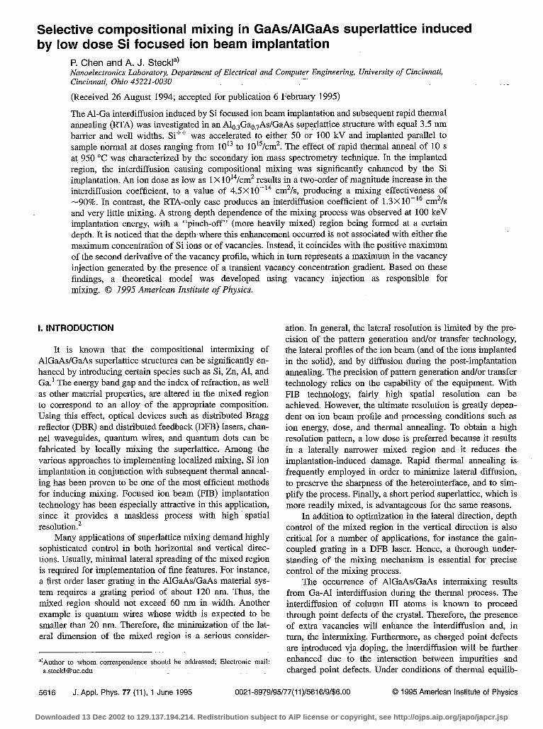
FIG. 4. SIMS depth profiles of Al in superlattices after 100 keV Si F’D implantation and RTA at 950 “C for 10 s with various doses: (a) 4X1013 cm-‘, (b) 1X1014 cm-‘, (c) 3X lOI cm-*.
mixed samples, the normalized standard deviation, as well as the mixing parameter, were computed over the superlattice region as a function of ion dose, as shown in Fig. 5(a). No significant mixing was induced solely by thermal annealing or ion implantation. However, after implantation and subse- quent annealing, the degree of mixing was dramatically en- hanced. Even a dose as low as 1 X lOi cm-’ could generate 72% mixing. A dose of 1 X10¹⁴ cmm2 produced a mixing parameter of 0.89. This is the lowest ion dose necessary for nearly complete mixing reported to date for either FIB or broad beam implantation. This result could be due to the combined effect of FIB implantation, which usually creates more point defects than conventional ion beam implantation, and to the short period superlattice which is more readily mixed. Tripling the dose to 3 X 10¹⁴ cmW2 results in an in- crease in mixing by only 0.05 to a value of 0.94.
In the samples subjected to 100 keV ion implantation, the degree of mixing after RTA is visibly dependent upon the
2 1.0 ? ‘Z .crr 06 5 0.8 - -p ‘“0 $? 0.6 - sa,
3 .83 0.4 -
Tijz E 5 0.2 - z
as grown -_ Y I I I I , ,
RTA-only /a) $O.O o Im lant-only
8 0.2 FIB+RTA
1x~o’~x,013 0.6 ’ 0 14
‘“:o 2$!o’;x,01 0.8 R
$1.0 0123456789
Processing Condition
Ls E e
I I 04 -
200keV FIB +RTA
/:
RTA-only a I I
1013 lOI lOi Dose (cm”)
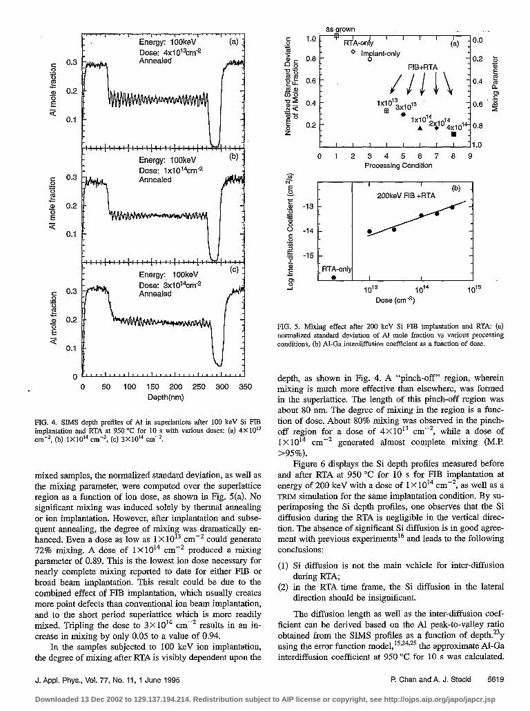
lJIG. 5. Mixing effect after 200 keV Si FIEF tiplantation and RTA: (a) normalized standard deviation of Al mole fraction vs various processing conditions, (b) Al-Ga interdiffusion coefficient as a function of dose.
depth, as shown in Fig. 4. A “pinch-off” region, wherein mixing is much more effective than elsewhere, was formed in the superlattice. The length of this pinch-off region was about 80 nm. The degree of mixing in the region is a func- tion of dose. About 80% mixing was observed in the pinch- off region for a dose of 4X10¹³ cmb2, while a dose of 1 X 10¹⁴ cme2 generated almost complete mixing (ME >95%).
Figure 6 displays the Si depth profiles measured before and after RTA at 950 Y! for 10 s for FIB implantation at energy of 200 keV with a dose of 1 X 10¹⁴ cmm2, as well as a TRIM simulation for the same implantation condition. By su- perimposing the Si depth profiles, one observes that the Si diffusion during the RTA is negligible in the vertical direc- tion. The absence of significant Si diffusion is in good agree- ment with previous experiments16 and leads to the following conclusions:
(1) Si diffusion is not the main vehicle for inter-diffusion during RTA;
(2) in the RTA time frame, the Si diffusion in the lateral direction should be insignificant.
The diffusion length as well as the inter-diffusion coef- ficient can be derived based on the Al peak-to-valley ratio obtained from the SIMS profiles as a function of depth.23y using the error function mode1,‘5,24P25 the approximate Al-Ga interdiffusion coefficient at 950 “C for 10 s was calculated.
J. Appl. Phys., Vol. 77, No. 11, 1 June 1995 P. Chen and A. J. Steckl 5619
Downloaded 13 Dec 2002 to 129.137.194.214. Redistribution subject to AIP license or copyright, see http://ojps.aip.org/japo/japcr.jsp

(a) As-implanted (SIMS)
=&s..+@--‘-+*““~~~ s - 0
(c) TRIM Simulation
L~1~1~l~Ll~l~1 0 50 100 150 200 250 300 350 400
Depth (nm)
FIG. 6. Comparison of Si depth distributions before and after RTA for Si FLB implantation at 200 keV with dose of 1 X 1014 cm-*. RTA condition: 950 “C, 10 s. The Si profiles were measured with SIh4S and simulated with TFUM.
Despite the fact that the period of the superlattice used in this work does not fulfill the condition of thick cladding layer assumed for this model, the calculated interdiffusion coeffi- cient from the RTA-only sample (1.3 X lo-l6 cm’/s) is in good agreement with previously published results (9X lo-l7 cm2/s) obtained at the same temperature with furnace anneal- ing in a structure with the same composition but with much thicker barrier layers. l5
19
G- E
s 5 .- P
18
E @
6 G
17
$ 1
16
c? E 2.
O’ .- P
18
E 8 5
0 17 iii E -I
16
~‘““““““““““““““““‘I 2OOkeV (-4 0.3
!+ E
0.2 g l+i a, it
0.1 3
0 50 100 150 200 250 300 ‘350
Depth (nm)
FIG. 7. Si and Al depth profiles of annealed superlattice produced by Si FIB implantation with 1 X 1014 cm-* dose at energy of : (a) 200 keV, (b) 100 keV.
5620 J. Appl. Phys., Vol. 77, No. 11, 1 June 1995
For uniform mixing (200 keV), the average interdiffu- sion coefficients are only a function of dose and the results are shown in Fig. 5(b). As an example, the dose of 1X10f4 cm -2 results in a two-order of magnitude increase in the diffusion coefficient, to a value of 4.5X lo-l4 cm2/s, in con- trast to 1.3X lo-l6 cm2/s from RTA-only. Similar calcula- tions were made for depth-dependent mixing produced by Si FIB implantation at 100 keV. Si and Al depth profiles for implantation energies of 100 and 200 keV are shown in Fig. 7 for an implantation dose of 1X10¹⁴ cme2. Interdiffusion coefficient calculations were performed based on these pro- files: As shown. in Fig. 8, for 100 keV implantation with a dose of 1X lOI cmm2 , the interdiffusion coefficient in the pinch-off region, is approximately ten times larger than that obtained in the rest of the superlattice structure. For compari- son, the interdiffusion coefficient of uniform mixing pro- duced by implantation at 200 keV with that same dose is also presented in Fig. 8.
IV. ANALYSIS AND MODEL
Based on the experimental results presented above, an understanding of the mechanisms involved in Si implantation-enhanced-mixing has been pursued in order to optimize and precisely control the process of locally selec- tive mixing.
The interdiffusion between AlGaAs and GaAs layers proceeds through point defects.’ In our case, we assume that the As pressure is high enough to provide an As-rich anneal- ing environment. In this condition, the major point defect associated with Si ion implantation has been suggested2’ to be the triply charged vacancy on the Ga site, VC,’ . Usually, these vacancies are concentrated in the GaAs instead of the AlGaAs layers, since the bond between Al and As is more . difficult to break. At annealing temperatures, these defects are mobile and are able to diffuse through the heterointerface in a multi-step process summarized’ in the following expres- sion:
~G,*~G,+(z,l+,)~(~Ga+zAl)+~AI*~VAI~ (1)
where VA1 and IAl are the Al vacancy and interstitial, respec- tively.
The attractive interaction between an impurity ion and a charged point defect provides an additional contribution to this process. By using the charged vacancy as a vehicle, the Al-Ga atomic interdiffusion can be significantly enhanced. Three elements play key roles in this process: (1) the As vapor pressure, (2) the doping, (3) the point defect nonequi- librium concentration induced by chemical or physical pro- cesses.
Usually, the As vapor pressure affects the interdiffusion process a great deal. The diffusion coefficient for column III atoms (Ga, Al, etc.) can be expressed as:*
Dm=f,Dv(P*,~)“4+f2DI(PAsq)-1’4, (2)
where D, and D, represent the diffusion coefficient for the column III vacancy and interstitial, respectively. PAs4 repre- sents the As vapor pressure. This expression indicates that D, is governed by V,, for sufficiently high As pressure and
P. Chen and A. J. Steckl
Downloaded 13 Dec 2002 to 129.137.194.214. Redistribution subject to AIP license or copyright, see http://ojps.aip.org/japo/japcr.jsp

by Io, for sufficiently low As pressures. The GaAs sandwich structure which we have used in the RTA process provides an As-rich condition and, therefore, the diffusion is column III vacancy dominated diffusion.
Previous studies show that the thermal equilibrium con- centration of charged point defects is enhanced by doping, the so-called Fermi-level effect.“3 Those enhanced charged point defects in turn make a significant contribution to the Ga-Al interdiffusion coefficient DGamAI, which is approxi- mate equal to D, and D,, According to the Fermi-level effect model, the presence of the dopant (and not necessarily its motion) is the factor enhancing the Ga-Al interdiffusion process. For n-doped material under thermal equilibrium, the equilibrium Al diffusivity3 is given by:
5 $! b E E .a, g $ 0 c .P 2 -z d S
150 Depth(nm)
D A&q= (3)
where n and ni are the free electron concentrations of ,doped and intrinsic material, respectively. In the Fermi-level model, the maximum impurity concentration is associated with the maximum vacancy concentration and hence will induce maximum mixing. This model describes a steady state pro- cess and requires a thermal equilibrium circumstance.
In the RTA time frame (t-10-30 s), a large portion of the thermal process has experienced a nonequilibrium state. During this period, the vacancies diffuse in their own sublat- tice due to the gradient of vacancy concentration created by ion implantation. The Al-Ga interdiffusion is enhanced not only by the presence of excess vacancies but also by the motion of point defects. In order to describe the Al-Ga inter- diffusion process during RTA, a model of the transient Al interdiffusion coefficient was proposed by Kahen and Rajeswaran:t8
C” DAI=DA~,~ 7'
where C, and C,,, represent the total transient and thermal equilibrium vacancy concentration at the annealing tempera- ture. The transient defect model described in Eq. (4) suggests that the excess vacancy concentration controls the interdiffu- sion coefficient, which in turn determines the degree of in- termixing.
However, the transient diffusion model of Kahen and Rajeswaran does not correctly predict18 some aspects of in- terdiffusion, especially at depths greater than R, . From the SIMS profiles for 100 keV Si implanted superlattice (see Fig. 4), the mixing at depths from -150 nm to 220 nm is much more effective than elsewhere in the superlattice structure. With increasing dose, the peak-to-valley ratio in this region is significantly decreased and eventually a complete pinch- off is formed at depth of 170 nm. It is important to note that the depth of this maximum mixing did not coincide with the maximum of either the Si (at -100 nm) or vacancy concen- trations. The vacancy, as well as the impurity, concentration is clearly still an important factor here because the average degree of mixing over the entire superlattice is proportional to the dose. However, it is evident that in the pinch-off re- gion the mixing is no longer exclusively dominated by either the impurity concentration or the vacancy concentration.
FIG. 8. Al-Ga interdiffusion coefficient as function of depth for FIB implan- tation with dose of 1X1014 cm-* at 100 and 200 keV after 950 “C, 10 s RTA.
Similar depth-dependent phenomena have been observed by a number of groups’3>‘6-‘8 from various superlattice struc- tures and processing conditions, including the authors of the transient model. In the results reported by Kahen et a1.,25-27 the mixing abruptly increases in the region that is beyond the Ri, and cannot be interpreted by the transient defect model they proposed for the RTA situation.
The depth distribution of Si atoms and vacancies pro- duced by the implantation experiments were simulated with the TRIM27 program. An example for a dose of 1 X 10¹⁴ cmM2 is shown in Fig. 9(a). Si depth profiles computed by TRIM were in good agreement with those measured by SWIS. To explore the mechanism of the enhanced mixing in the pinch- off region, we have calculated the second derivative of the vacancy concentration (SDVC)
SDVC= J2C”(XJ)
dx2 .
The calculated SDVC depth distribution and the correspond- ing interdiffusion coefficient are shown in Figs. 9(b) and 9(c) for the dose of 1 X 10¹⁴ cmw2. From Fig. 9(b), one can clearly note that the pinch-off mixing takes place in the region where SDVC is positive. Furthermore, the pinch-off point coincides with the peak SDVC level. In another aspect, Fig. 9(c) shows that interdiffusion is greatly enhanced by a posi- tive SDVC.
Following the approach of Kahen et &,‘6-18 the vacancy concentration time- and space-dependence are interrelated by
JC,(x,t> ~2~,(w) rc,(w>-C,,e,l dt =D, ax2 - , 7 (6)
where r is the decay time constant of vacancies. The first term on the right side of the equation represents the vacancy gradient (the cause of diffusion) and the second term repre- sents the vacancy recombination. The recombination term will always cause a reduction of the vacancy concentration. Near the top surface, where SDVC is large and negative and (C,-Cc, q) is al so very large, the sign of dC,ldt is negative and its amplitude is large. This would indicate a rapid de-
J. Appl. Phys., Vol. 77, No. 11, 1 June 1995 P. Chen and A. J. Steckl 5621
Downloaded 13 Dec 2002 to 129.137.194.214. Redistribution subject to AIP license or copyright, see http://ojps.aip.org/japo/japcr.jsp

m^ 22 ‘E 2.
L111’,1”‘,1’11 InI, ,.S *.‘- . ..-----. -_sm,*,,u _
, - *__ . . si + (a) --._._
-. ‘. -..
-“‘\ -
4- Vat. “?,
1.. : : : ? ::’
I ” “I” g ‘I”” 04 1
SDVC
Iii-
k ‘, 2.
Y 2:
19
‘? E 9
18 .g L ti 2
17 8 ii5 m 4
16
5 E -0.2 i
CL a,
0.1 E” 3
50 100 150 200 250
Depth (nm)
FIG. 9. Mechanism analysis of depth-dependent mixing in superlattice after Si FIB (100 keV, 1 X 1014 cm-‘) implantation and RTA: (a) vacancy and Si ions depth profiles, (b) SDVC and Al profiles, (c) SDVC and interdiffusion coefficient.
crease in the vacancy concentration in this region. At values of depth for which SDVC is positive, the sign of dC,(x,t)ldt is determined by the subtraction in the right side of Eq. (6). When D,[a20,(x,t)ldx2]-[C,(x,t)- CU,eq]/rBO. a positive dC,(x,t)ldt is obtained, indicating that the vacancies are in- jected into the region. This is presumably the pinch-off re- gion, where SDVC is large and positive and a high level of mixing occurs, as shown in Fig. 9(b). As one proceeds deeper into the SL stack, SDVC continues to be positive but its amplitude decreases, as does that of the vacancy concen- tration. Since an absence of mixing is observed in the pinch- off region, it is assumed that here Xl& is determined by the decreasing SDVC.
The vacancy decay time constant is of the order of a few seconds.17 Therefore, in the context of rapid thermal anneal- ing, increasing the anneal time beyond 10 s will not signifi-
cantly increase the level of mixing. However, this conclusion does not apply to furnace annealing because of significant impurity diffusion’~3*2* which occurs during a much longer time frame.
Turning our attention again to the comparison between SDVC and the interdiffusion coefficient as a function of depth [Fig. 9(c)], we assume that the more sharply peaked profile of the interdiffusion coefficient is due to the reducing effect of vacancy recombination on vacancy injection.
Based on these assumptions, our analysis suggests that the AI-Ga interdiffusion is enhanced by the vacancy injection that takes place in the region where SDVC is positive and sufficiently large. This injection, generated by the presence of a gradient in the transient vacancy concentration (and modified by the recombination of excess vacancies) is pre- sumably responsible for the enhanced mixing occurring in the pinch-off region.
Through curve fitting, an exponential form of the inter- diffusion coefficient is derived as a function of SDVC:
D,,=pexp( f2 ‘?$7t)) 1 (7)
where Q is a constant. p includes the nonequilibrium effect of transient-enhanced interdiffusion’* during RTA which was previously considered. The exponential term represents the enhanced interdiffusion effect of vacancy injection. D (Al,eq) is the interdiffusion coefficient under equilibrium condition and is proportional to the impurity concentration.
Considering the experimental model described by Eq. (7) and the conventional transient defect model given in Eq. (4), we propose the following expression for the Al-Ga inter- diffusion coefficient in the time frame of RTA:
(8)
where the term cp represents the influence of vacancy recom- bination.
Equation (8) indicates that the Al-Ga interdiffusion is significantly affected by the motion of vacancies that occurs during the early period of rapid thermal annealing due to the implantation-induced gradient. In this period, nonequilibrium processes take place. Point defects, presumably charged va- cancies, diffuse quickly in their own sublattice, while Si dif- fusion is not yet significant. The interdiffusion is enhanced at all the depths by excess charged vacancies (V,:) due to dop- ing, and it is most strongly enhanced in the region into which the vacancies are injected. The vacancy injection greatly en- hances the Al-Ga interdiffusion and becomes a decisive fac- tor in the nonequilibrium period of annealing. However, this vacancy injection process will be saturated in a few seconds because a thermal equilibrium of the vacancy concentration profile will be established. Therefore, the mixing usually does not increase appreciably as the annealing time is in- creased beyond a certain point.16 When the annealing time is long enough (as in furnace annealing), the mixing process is under dynamic equilibrium and it is dominated by the impu- rity concentration as well as impurity diffusion, as described in the Fermi-level effect and impurity diffusion models.
5622 J. Appl. Phys., Vol. 77, No. 11, 1 June 1995 P. Chen and A. J. Steckl
Downloaded 13 Dec 2002 to 129.137.194.214. Redistribution subject to AIP license or copyright, see http://ojps.aip.org/japo/japcr.jsp
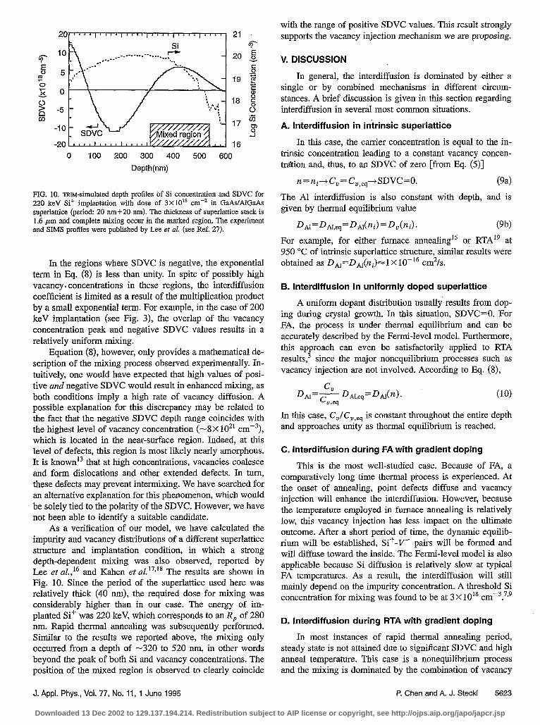
with the range of positive SDVC values. This result strongly supports the vacancy injection mechanism we are proposing.
20
19
18
17
16
67 k s 0’ ‘Z E E $ c 8 iiti 8 -I
0 100 200 300 4qo 500 600
Depth(nm)
FIG. 10. IruM-simulated depth profiles of Si concentration and SDVC for 220 keV Si’ implantation with dose of 3x10” cm-* in GaAs/AlGaAs superlattice (period: 20 nm+20 nm). The thickness of superlattice stack is 1.6 pm and complete mixing occur in the marked region. The experiment and SIMS profiles were published by Lee et al. (see Ref. 27).
In the regions where SDVC is negative, the exponential term in Eq. (8) is less than unity. In spite of possibly high vacancy. concentrations in these regions, the interdiffusion coefficient is limited as a result of the multiplication product by a small exponential term. For example, in the case of 200 keV implantation (see Fig. 3), the overlap of the vacancy concentration peak and negative SDVC values results in a relatively uniform mixing.
Equation (S), however, only provides a mathematical de- scription of the mixing process observed experimentally. In- tuitively, one would have expected that high values of posi- tive and negative SDVC would result in enhanced mixing, as both conditions imply a high rate of vacancy diffusion. A possible explanation for this discrepancy may be related to the fact that the negative SDVC depth range coincides with the highest level of vacancy concentration (-8X 10²* cmv3), which is located in the near-surface region. Indeed, at this level of defects, this region is most likely nearly amorphous. It is knownI that at high concentrations, vacancies coalesce and form dislocations and other extended defects. In turn, these defects may prevent intermixing. We have searched for an alternative explanation for this phenomenon, which would be solely tied to the polarity of the SDVC. However, we have not been able to identify a suitable candidate.
As a verification of our model, we have calculated the impurity and vacancy distributions of a different superlattice structure and implantation condition, in which a strong depth-dependent mixing was also observed, reported by Lee et al,*’ and Kahen et al.‘7~‘8 The results are shown in Fig. 10. Since the period of the superlattice used here &as relatively thick (40 nm), the required dose for mixing was considerably higher than in our case. The energy of im- planted Sif was 220 keV, which corresponds to an R, of 280 nm. Rapid thermal annealing was subsequently performed. Similar to the results we reported above, the mixing only occurred from a depth of -320 to 520 run, in other words beyond the peak of both Si and vacancy concentrations. The position of the mixed region is observed to clearly coincide
V. DISCUSSION
In general, the interdiffusion is dominated by either a single or by combined mechanisms in different circum- stances. A brief discussion is given in this section regarding interdiffusion in several most common situations.
A. lnterdiff usion in intrinsic superlattice
In this case, the carrier concentration is equal to the in- trinsic concentration leading to a constant vacancy concen- tration and, thus, to an SDVC of zero [from Eq. (5)]
Tl=ni--+C,=C ,,,tSDVC=O. Pa>
The Al interdiffusion is also constant with depth, and is given by thermal equilibrium value
DAI=DAI,~~ =DAl(ni)=D,(ni). (9b) For example, for either furnace annealing15 or RTA” at 950 “C of intrinsic superlattice structure, similar results were obtained as D,1=DA,(ni)~l X lo-l6 cm2/s.
B. interdiffusion in uniformly doped superlattice
A uniform dopant distribution usually results from dop- ing during crystal growth. In this situation, SDVC=O. For FA, the process is under thermal equilibrium and can be accurately described by the Fermi-level model. Furthermore, this approach can even be satisfactorily applied to RTA results,3 since the major nonequilibrium processes such as vacancy injection are not involved. According to Eq. (8),
C” DAI=C D~l,e~ =D,,(n).
u,eq (10)
In this case, CJC,,,, is constant throughout the entire depth and approaches unity as thermal equilibrium is reached.
C. Interdiffusion during FA with gradient doping
This is the most well-studied case. Because of FA, a comparatively long time thermal piocess is experienced. At the onset of annealing, point defects diffuse and vacancy injection will enhance the interdiffusion. However, because the temperature employed in furnace annealing is relatively low, this vacancy injection has less impact on the ultimate outcome. After a short period of time, the dynamic equilib- rium will be established, Sif-V- pairs will be formed and will diffuse toward the inside. The Fermi-level model is also applicable because Si diffusion is relatively slow at typical FA temperatures. As a result, the interdiffusion will still mainly depend on the impurity concentration. A threshold Si concentration for mixing was found to be at 3 X 101’ cm-3.7T9
D. Interdiffusion during RTA with gradient doping
In most instances of rapid thermal annealing period, steady state is not attained due to significant SDVC and high anneal temperature. This case is a noneqtiilibrium process and the mixing is dominated by the combination of vacancy
J. Appl. Phys., Vol. 77, No. 11, 1 June 1995 P. Chen and A. J. Steckl 5623
Downloaded 13 Dec 2002 to 129.137.194.214. Redistribution subject to AIP license or copyright, see http://ojps.aip.org/japo/japcr.jsp

injection, transient vacancy concentration, and impurity con- centration. At all depths within the superlattice, the interdif- fusion is enhanced with respect to the undoped superlattice case. The greatest enhancement takes place in the vacancy injection region. Equation (8) provides the description of this most complex interdiffusion process. The effectiveness of this equation is verified by the depth-dependent mixing pre- sented in Sec. III of this article and the results published by other group~.‘~*‘~-‘~
VI. OPTIMIZATION OF MIXING PROCESS
The optimization of selective mixing with minimal lat- eral profile can be achieved under the following consider- ations:
employing a short period superlattice; using rapid thermal annealing with minimal thermal bud- get; using low dose impurity implantation; minimizing the dose by properly utilizing the enhance- ment in vacancy injection region.
In our experiments, the short period superlattice with a 7 nm period is proven to be quite effective in terms of mixing with low dose. Meanwhile, the RTA condition of 10 s at 950 “C is capable of rendering the implanted superlattice re- gion mixed and removing the damage induced by implanta- tion with moderate dose.22 The dose of 1 X lOI4 cm-’ at an energy of 200 keV provides a satisfactory mixing result throughout the entire depth of the superlattice. The same dose at an energy of 100 keV leads to a complete mixing in the pinch-off region. The selection of ion energy and dose is based on several considerations:
(4
64
(4
trade-off between more complete mixing with higher dose and smaller lateral profile with lower dose; smaller lateral ion straggling at lower energy and finer focused ion beam at higher energy;
more complete mixing but relatively small mixing depth with lower energy and less complete but more uniform mixing with higher energy.
The optimization can therefore be carried out with re- spect to the requirement of a specific application. As an ex- ample, we have demonstrated the fabrication of a DBR laser grating structure by periodically mixing the superlattice us- ing a focused Si ion beam at 200 keV with dose of a 1 X lOI4 cmm2 and subsequent RTA. The details of this result were presented elsewhere.lg
VII. SUMMARY
In summary, we have studied the Sif+ FIB-induced mix- ing of an AlO.,GaeYAs/GaAs superlattice structure. A fairly complete mixing can be achieved with a relatively low dose at a certain depth. This result can be utilized to minimize lateral spread, reduce damage, and achieve depth control.
The mechanism for the depth-dependence and pinch-off mix- ing effect were discussed. Nonequilibrium vacancy injection has been suggested as being responsible for the high degree of mixing in the pinch-off region. Based on experimental results, a theoretical model has been proposed to describe the inter-diffusion as well as the mixing process in the time scale of RTA.
ACKNOWLEDGMENTS
The authors would like to thank R. Kolbas for the MBE growth, S. Novak for the SIMS measurement and many re- lated discussions, and A. G Choo, J. T. Boyd, and H. E. Jackson for many useful discussion. Partial support for this work from the National Science Foundation and the Materi- als Directorate, Wright Laboratory at the Wright-Patterson Air Force Base is acknowledged.
‘D. G. Deppk and N. Holonyak, Jr., J. Appl. Phys. 64, R93 (1988). 2K. Ishida, E. Miyauchi, T. Morita, T. Takamori, T. Fukunaga, H. Hash-
imoto, and H. Nakashima, Jpn. J. Appl. Phys. 26, L285 (1987). 3T. Y. Tan, U. Gosele, and S. Yu, Crit. Rev. Solid State Mater. Sci. 17, 47
(1991). 4E. Dobisz, R. Marrian, H. Craighead, S. Schwarz, and J. Harbison, J. Vat.
Sci. Technol. B 7, 2053 (1989). ‘K. Ishida, K. Matsui, T. Fukunaga, J. Kobayashi, T. Morita, E. Misauchi,
and H. Nakashima, Appl. Phys. Lett. 51, 109 (1987). 6J. Kobayashi, T. Fukunaga, K. Ishida, H. Nakashima, J. Flood, G. Bahir,
and L. Men, Appl. Phys. Lett. 50, 519 (1987). 7 J. Kobayashi, M. Nakajima, Y. Bamba, T. Fukunaga, K. Matsui, K. Ishida,
H. Nakashima, and K. Ishida, Jpn. J. Appl. Phys. 25, L385 (1986). ‘J Kobayashi; M. Nakajima, T. Fukunaga, T. Takamori, K. Ishida, H. Na-
kashima, and K. Ishida, Jpn. J. Appl. Phys. 25, L736 (1986). ’ K. Matsui, J. Kobayashi, T. Fukunaga, K. Ishida, and H. Nakashima, Jpn.
J. Appl. Phys. 25, L651 (1986). ‘Oh? Kawabe N. Matsuura, N. Shin&u, F. Hasegawa, and Y. Nannichi, Jpn.
J. Appl. Ph;s. 23, L623 (1984). “Y. Hirayama, Y. Horikoshi, and H. Okamoto, Jpn. J. Appl. Phys. 23, 1568
(1984). “T. Venkatesan, S. Schwarz, D. Hwang, R. Bhat, M. Koza, H.Yoon, P. Mei,
Y. Arakawa, and A. Yariv, Appl. Phys. Lett. 49,701 (1986). 13S A. Schwarz T. Venkatesan, R. Bhat, M. Koza, H. Yoon, Y. Arakawa,
and P. Mei, Mater. Res. Sot. Symp. Proc. 56, 321 (1986). t4S Schwarz*T. Venkatesan, D. Hwang, H. Yoon, R. Bhat, andY. Arakawa,
Appl. Phys: Lett. 50, 281 (1987). “T. E. Schlesinger and T. Kuech, Appl. Phys. Lett. 49, 519 (1986). 16S. T. Lee, G. Braunstein, P. Fellinger, K. Kahen, and G. Rajeswaran, Appl.
Phys. Lett. 53, 2531 (1988). t7K. Katten, G. Rajeswaran, and S. Lee, Appl. Phys. Lett. 53, 1635 (1988). “K. Kahen and G. Rajeswaran, J. Appl. Phys. 66, 545 (1989). “A. J. Steckl, P. Chen, A. Choo, H. Jackson, 5. Boyd, A. Ezis, R Pronko, S.
Novak, and R. Kolbas, Mater. Res. Sot. Symp. Proc. 281, 319 (1993). “M. Greiner and F. Gibbons, Appl. Phys. lett. 44, 751 (1984). “M. Greiner and J. Gibbons, J. Appl. Phys. 57, 5181 (1985).\ *‘A Steckl, P. Chen, A. Choo, H. Jackson, J. Boyd, P. Pronko, A. Ezis, and
R: Kolbas, Mater. Res. Sot. Symp. Proc. 240, 703 (1992). 23P. Mei, Y. Yoon, T. Venkatesan, S. Schwarz, and J. Harbison, Appl. Phys.
Lett. 50, 1823 (1987). %K. Kash, B. Tell, P. Grabbe, E. Dobisz, H. Craighead, and M. Tamargo, J.
Appl. Phys. 63, 190 (1987). 25L. Chang and A. Koma, Appl. Phys. Lett. 29, 138 (1976). %L. Pavesi, N. Ky, J. Ganiere, F. Reinhart, N. Baba-Ali, I. Harrison, B.
Tuck, and M. Henini, J. Appl. Phys. 71, 2225 (1992). 27 J F Ziegler, J. P. Biersack, and U. Littmark, Stopping and Range of Ions . .
in Mutter (Pergamon, New York, 1988), Vol. 1.
5624 J. Appl. Phys., Vol. 77, No. 11, 1 June 1995 P. Chen and A. J. Steckl
Downloaded 13 Dec 2002 to 129.137.194.214. Redistribution subject to AIP license or copyright, see http://ojps.aip.org/japo/japcr.jsp