Selection Guide for electronic components …...Electronic reliability modelling has been improved...
92
This document is the property of the Risk management Institute (Institut pour la Maîtrise des Risques) Its contents cannot be reproduced nor disclosed in whole or in part without written authorisation Selection Guide for electronic components predictive reliability models Copyright IMdR – Octobre 2009
Transcript of Selection Guide for electronic components …...Electronic reliability modelling has been improved...

This document is the property of the Risk management Institute (Institut pour la Maîtrise des Risques) Its contents cannot be reproduced nor disclosed in whole or in
part without written authorisation
Selection Guide for electronic components predictive reliability
models
Copyright IMdR – Octobre 2009


S E L E C T I O N G U I D E F O R E L E C T R O N I C
C O M P O N E N T S P R E D I C T I V E R E L I A B I L I T Y
M O D E L S
October 2009
Page 3
S U M M A R Y
1. GENERAL INFORMATION ........................................................................................ 5
1.1. Selection guide objectives ................................................................................................................ 5
1.2. Referenced Documents ..................................................................................................................... 5
1.3. Selection guide elaboration context ................................................................................................ 6
1.3.1. General context ............................................................................................................................. 6
1.3.2. Needs of the reliability handbooks users ...................................................................................... 6
1.3.3. Selection criteria elaboration method ............................................................................................ 7
1.4. Selection guide organisation ............................................................................................................ 8
2. ELECTRONIC RELIABILITY HANDBOOKS STUDIES ............................................. 9
2.1. General description ............................................................................................................................ 9
2.1.1. Chronology .................................................................................................................................... 9
2.1.2. MIL-HDBK-217 ............................................................................................................................ 10
2.1.3. RDF93 ......................................................................................................................................... 13
2.1.4. UTE-C 80810 .............................................................................................................................. 14
2.1.5. FIDES .......................................................................................................................................... 17
2.1.6. 217Plus ....................................................................................................................................... 20
2.2. Comparison of generic aspects ...................................................................................................... 22
2.2.1. Operational feedback used for the handbooks construction ....................................................... 22
2.2.2. Operating hours and calendar hours failure rate ........................................................................ 22
2.2.3. Comparison of the equipment failure rate ................................................................................... 23
2.2.4. Consistency of the modellings .................................................................................................... 24
3. PRINCIPLES OF RELIABILITY MODELS SELECTION .......................................... 26
3.1. Selection criteria related to generic aspects ................................................................................. 27
3.1.1. Selection criteria related to the contextual constraints ................................................................ 27
3.1.2. Selection criteria in regard to the operational constraints ........................................................... 32
3.1.3. Selection criteria in regard to the methodological constraints ..................................................... 38
3.2. Selection criteria related to technical constraints ........................................................................ 43
3.2.1. Unmodeled components ............................................................................................................. 44
3.2.2. Non operating phase not modelized ........................................................................................... 45
3.2.3. Early failure period not taken into account .................................................................................. 46
3.2.4. Influence of thermal cycles modelling ......................................................................................... 46
3.2.5. Sensitivity with the assumptions ................................................................................................. 48
3.2.6. Induced stresses ......................................................................................................................... 48
3.2.7. Modelling of complex environment ............................................................................................. 49
3.2.8. Implicit taking into account of monitoring and improvement policy ............................................. 49
3.2.9. Process minimising without justification the failure rate .............................................................. 49
3.3. Selection criteria related to the components technology ............................................................ 49
3.3.1. Passive components ................................................................................................................... 50
3.3.2. Discrete active components ........................................................................................................ 58
3.3.3. Integrated circuits digital and linear ............................................................................................. 62
3.3.4. Hybrid Circuits ............................................................................................................................. 69
3.3.5. Electro-mecanical components ................................................................................................... 71

S E L E C T I O N G U I D E F O R E L E C T R O N I C
C O M P O N E N T S P R E D I C T I V E R E L I A B I L I T Y
M O D E L S
October 2009
Page 4
3.3.6. Miscellaneous components ......................................................................................................... 76
4. USE OF THE IMDR SELECTION HANDBOOK ....................................................... 77
4.1. STEP 1 Ranking of the reference handbooks ............................................................................... 80
4.2. STEP 2 Analysis of the overall limits of the handbook ................................................................ 82
4.3. STEP 3 Identification of the recommendations/solutions in relation with the constraints of use of the reference handbook (s) ............................................................................................................ 83
4.4. STEP 4 Reference Document for reliability analysis constitution .............................................. 84
4.5. Examples of using this Selection guide ........................................................................................ 85
4.5.1. Example 1 ................................................................................................................................... 85
1.1.1. Example 2 ................................................................................................................................... 90

S E L E C T I O N G U I D E F O R E L E C T R O N I C
C O M P O N E N T S P R E D I C T I V E R E L I A B I L I T Y
M O D E L S
October 2009
Page 5
1. GENERAL INFORMATION
1.1. SELECTION GUIDE OBJECTIVES
This selection guide aims at suggesting a recognized electronic reliability handbook selection method. Justification information used for project modelling is also provided.
For that purpose, this selection guide:
- defines the needs and the industrial constraints in the achievement of an electronic predictive reliability assessment,
- presents a reliability handbook analysis for each of these needs and identifies the one or those that best correspond(s),
- identifies each reliability handbook constraints and limitations that could prevent on its erroneous use,
- carries out a comparative analysis of the main components families according to the different reliability handbooks and synthesises the user needs with regards to these components families.
1.2. REFERENCED DOCUMENTS
The main documents used to constitute this selection guide are the following ones:
[1] MIL HDBK 217 F + N2 – Rome Air Center. - 28 February 1995
[2] RDF 93 - CNET– June 1993
[3] UTE 80-810 - August 2005
[4] FIDES 2004A – Issue A
[5] 217Plus– 26 May 2006
[6] REVISION OF ENVIRONMENTALFACTORS FOR MIL-HDBK-217B – TR-80-229
[7] IMPACT OF NONOPERATING PERIODS ON EOUIPMENT RELIABILITY – TR-85-91
[8] RELIABILITY PREDICTION MODELS FOR DISCRETE SEMICONDUCTOR DEVICES – TR-88-97
[9] RELIABILITY ANALYSIS/ASSESSMENT OF ADVANCED TECHNOLOGIES – TR-90-72
[10] RELIABILITY ASSESSMENT OF CRITICAL ELECTRONIC COMPONENTS – TR-92-197
[11] NAVSEA
[12] GIFAS 26 March 2006 workshop
[13] Modélisation des coûts de cycle de vie : prévision des coûts de maintenance et de la fiabilité Application à l’aéronautique N°2005-1 M. GLADE
[14] Application Note AN-1078 – An Examination of Changes Imposed by Revised Hybrid Models When Calculating MTBF Values using MIL-HDBK 217F, Notice 1 & 2 – International Rectifier
[15] Journal of the Reliability Information Analysis Center from 1998 to 2008

S E L E C T I O N G U I D E F O R E L E C T R O N I C
C O M P O N E N T S P R E D I C T I V E R E L I A B I L I T Y
M O D E L S
October 2009
Page 6
[16] Dossier projet IMdR P07-05 “Constitution du référentiel de sélection des guides de fiabilité prévisionnelle des composants électroniques“
1.3. SELECTION GUIDE ELABORATION CONTEXT
1.3.1. GENERAL CONTEXT
This selection guide was worked out in the framework of the project IMdR P07-5.
This project aiming at the creation of a selection guide for the electronic components reliability predictive models grouped together the following companies:
- AREVA
- CNES,
- DGA/LRBA,
- EADS ASTRIUM,
- ZODIAC AEROSPACE,
- EDF,
- PSA,
- SNCF,
- TOTAL,
The complete work performed and achieved during this project is presented in project file IMdR P07-05 “Constitution du référentiel de sélection des guides de fiabilité prévisionnelle des composants électroniques “. This document can be bought at IMdR in accordance with the subscription conditions of this project.
1.3.2. NEEDS OF THE RELIABILITY HANDBOOKS USERS
The users' needs were determined on the basis of an investigation to a large sample of contributors representative of the main activity domains (civil and military aeronautics, space systems (satellites and ground segments), automotive, ground military, nuclear, petro-chemistry, railway).
The objective was to have a feedback on the use of the various reliability handbooks in terms of:
- identification of the needs for reliability assessment,
- used reliability handbooks and their selection constraints,
- disadvantages and advantages of their use,
- lacks and difficulties encountered,
- investment in terms of cost and skill.
This investigation confirmed the problems related to the electronic reliability prediction assessment handbooks and highlighted many selection criteria.

S E L E C T I O N G U I D E F O R E L E C T R O N I C
C O M P O N E N T S P R E D I C T I V E R E L I A B I L I T Y
M O D E L S
October 2009
Page 7
1.3.3. SELECTION CRITERIA ELABORATION METHOD
The users’ needs enabled to identify the constraints influencing the choice of a handbook.
The identified constraints are:
- Contextual constraints
- Operational constraints
- Methodological constraints
- Technical constraints
The selection criteria resulting from these constraints are presented at the beginning of each related section of the document.
Each reliability handbook (covered by this selection guide) has been analysed for each selection criterion in order to identify its responses.
The analyses carried out to constitute this selection guide are included in the analysis document "Dossier projet IMdR P07-5".

S E L E C T I O N G U I D E F O R E L E C T R O N I C
C O M P O N E N T S P R E D I C T I V E R E L I A B I L I T Y
M O D E L S
October 2009
Page 8
1.4. SELECTION GUIDE ORGANISATION
The general selection guide organisation is:
1. General information: this section presents the context in which this selection guide was developed and briefly describes the methodology used,
2. Electronic reliability handbooks studies
2.1. General description: this section presents the various reliability handbooks studied in this guide and identifies for each one of them the basic assumptions, models data sources and the models elaboration method.
2.2. Comparison of generic aspects : this section presents a comparative analysis of the reliability handbooks results for the same equipment in various environments. It also presents a consistency analysis of the models proposed by each reliability handbook.
3. Principles of reliability models selection:
3.1. Selection criteria related to generic aspects: this section presents the selection criteria corresponding to the selection of a reference reliability handbook for one project or more by considering the reliability handbooks in their globality compared to a large set of criteria.
3.2. Selection criteria related to technical constraints: this section presents the different constraints or difficulties that can be encountered when using a handbook.
3.3. Selection criteria related to the components technology: this section presents a comparative analysis of the reliability handbooks for the main families of electronic components performing for each one of them a summary compared to the various users needs.
4. Use of the IMdR selection guide: This section points out the principles of use of this selection guide and presents some practical examples.

S E L E C T I O N G U I D E F O R E L E C T R O N I C
C O M P O N E N T S P R E D I C T I V E R E L I A B I L I T Y
M O D E L S
October 2009
Page 9
2. ELECTRONIC RELIABILITY HANDBOOKS STUDIES
2.1. GENERAL DESCRIPTION
2.1.1. CHRONOLOGY
The studied reliability handbooks date back from the early 1990s to 2006.
Electronic reliability modelling has been improved within that time. The former handbooks handle the intrinsic random electronic components failures only, excluding the impact of either the design or the integration process which has to be considered in another way. The recent models propose various level approaches (component or equipment/system levels) with methods allowing taking into account the impact of the design or the integration on the product final reliability.
Moreover, the modelling of the electronic components intrinsic failures was subject to major changes. Former handbooks model a global failure mechanism of the component to which the acceleration factors apply. Recent handbooks model several failure mechanisms with individualised acceleration factors. At that time a model built on the physics of failures has been created (FIDES) whereas the other models keep on with an empirical approach.
The following diagram presents the release dates of the various electronic components predictive reliability handbooks:
Figure 1 : Reliability handbooks release dates
Nota: The figure 1 is not exhaustive in terms of reliability handbooks.
1965
M
IL-H
DB
K-2
17A
1973
M
IL-H
DB
K-2
17B
1979
M
IL-H
DB
K-2
17C
1982
M
IL-H
DB
K-2
17D
1986
M
IL-H
DB
K-2
17E
1991
M
IL-H
DB
K-2
17F
1992
M
IL-H
DB
K-2
17F
N1
1993
R
DF
93
1995
M
IL-H
DB
K-2
17F
N2
1997
U
TE
-C 8
0-8
10 (
1997
)
1998
R
DF
93 -
1998
2000
U
TE
-C 8
0810 (
RD
F20
00)
1999
P
RIS
M 1
.0
2005
P
RIS
M 1
.5
2006
217
Plu
s
2004
F
IDE
S
1960 1970 1980 1990 2000
2006
U
TE
-C 8
0811(F
IDE
S)
2005
IEC
62
380 (
UT
E-C
8081
0)

S E L E C T I O N G U I D E F O R E L E C T R O N I C
C O M P O N E N T S P R E D I C T I V E R E L I A B I L I T Y
M O D E L S
October 2009
Page 10
Main electronic evolutions since the 1990s are:
– Components reliability growth through production processes improvement.
– General improvement of the semiconductors performance with regards to:
� power components,
� performances in frequency,
� components integration level.
– Increase in surface mounted components proportion.
– Lead removal in the soldering.
Note that the current electronic components physical functioning principles already existed in the early 1990s disregarding the fact that their application areas have dramatically expanded since.
2.1.2. MIL-HDBK-217
Origin
The MIL-HDBK-217 (A issue) reliability handbook was first developed in the 1960s by the US Navy. It was at the time rather a reliability data base than a predictive model. The changes (from B to F) were developed by the RAC (Reliability Analysis Centre) of the US Air Force.
The last version of the handbook (F issue) dates back to 1990 with an overhaul in 1995 (Notice 2). It has not been updated since, and is not maintained anymore. In spite of that, it is nowadays considered as an international reference.
Nota: the CRANE division of the US navy is said to work on a G issue of the Mil-HDBK-217.

S E L E C T I O N G U I D E F O R E L E C T R O N I C
C O M P O N E N T S P R E D I C T I V E R E L I A B I L I T Y
M O D E L S
October 2009
Page 11
Models construction method and the operation feedback used
The MIL-HDBK-217 reliability handbook models were built according to an empirical approach. The influence factors were identified via the statistical samples analysis. Then they were modelled in an empirical way in order to match as much as possible the source data.
The operation feedback data used to build the models contained in this reliability handbook come from, by order of importance:
– US army maintenance data, – test results, – public information (literature), – information collected from electronic components manufacturers.
The data resulting from the US army maintenance services correspond to electronic items in service data collected between 1988 and 1990 from systems that were in service since the early 80s. Furthermore these equipment items are mainly on-board electronics items embedded on military aircrafts.
Mathematical modelling
The generic mathematical model type used in the MIL-HDBK-217 reliability handbook is a multiplicative one. This model frame is:
λ = λb.πS.πQ.πE
This multiplicative type component failure rate model consists in a basic failure rate λb to which influence corrective factors are applied.
This model corresponds to the general case. Some components such as integrated circuits use a different formula (λ = (C1.πT+C2.πE) .πQ.πL). This enables to make the difference between the temperature sensitive part of the component and the environment sensitive one .
Components families covered by the MIL-HDBK-217
The electronic or electromechanical components families covered by the reliability handbook MIL-HDBK-217 are:
– semiconductors : � Integrated circuits, � Hybrids, � Diodes, Thyristors, � Transistors, � Optoelectronics,
– Passive components: � Resistances, Potentiometers, � Capacitors, � Inductors (coils, transformers), � Quartz, � Filters,
– Active components (except from semiconductors) :
� Tubes, � Lasers,
– Electromechanical components: � Relays, � Switches, � Rotating devices (motors, resolvers…), � Meters (voltmeter, amperemeter…),
– Miscellaneous � Fuses, � Lamps,
– Printed circuit board (PCB)

S E L E C T I O N G U I D E F O R E L E C T R O N I C
C O M P O N E N T S P R E D I C T I V E R E L I A B I L I T Y
M O D E L S
October 2009
Page 12
Summary table:
MIL-HDBK-217
Gene
ral in
form
ation
Emitter RAC (Department of Defence – USA)
Principle of construction Statistic on operational feedback
Privileged application domain Military
Modelled failures Intrinsic
Unit of the modelling Failures per hour
Date of the last issue 1995
Handbook still maintained No
Software tools Integrated in almost all the reliability calculation software packages
Price (paper handbook) Free
Modelli
ng
Mathematical formula λ = λb.πS.πQ.πE
Methods - Part count - Part stress
Environment modelling - Environment categories
Generic parameters (part count)
- Technology of the component - Category of environment
Generic parameters (part stress)
- Technology of the component - Environment - Thermal stress – Electrical stress - Quality
Excluded parameters -
Remarks
- Internationally known handbook - Easy appropriation - Only one element in the mathematical formula (except
for the integrated circuits) - No explicit consideration of the non operating phases - Soldering not integrated into the failure rate of the
component (separate calculation)

S E L E C T I O N G U I D E F O R E L E C T R O N I C
C O M P O N E N T S P R E D I C T I V E R E L I A B I L I T Y
M O D E L S
October 2009
Page 13
2.1.3. RDF93
Origin
The RDF93 reliability handbook (Recueil de Fiabilité 93) was developed by the CNET (France Telecom) on the initiative of the French telephone operator France Telecom. This reliability handbook was published in 1993 and was overhauled in 1998. It has not been maintained since.
Its approach of the reliability is similar to the one proposed in the MIL-HDBK-217 reliability handbook.
Models construction method and operational feedback used
The various models contained in RDF93 reliability handbook were built according to an empirical approach like for the MIL-HDBK-217 reliability handbook.
The operational feedback used to build its models contained is not accessible. However, in its introduction, the following application fields are indicated as source of the field experience:
- Telecom – ground fixed not protected (Public phones), - Telecom / computers – ground fixed protected, - Railway – ground mobile
The operational feedback covers the period from the late 1980s to the early 1990s. The representativeness of the statistical samples as well as the number of operating hours used for the models construction has not been identified at the time of the study of this guide.
Mathematical modelling
The generic mathematical model used in the RDF93 reliability handbook is of multiplicative type. It consists in:
λ = λb.πS.πQ.πE
The RDF93 reliability handbook general model is identical to that of the reliability handbook MIL-HDBK-217 .
This model corresponds to the general case. As for the MIL-HDBK-217 reliability handbook, some components such as the integrated circuits use a different equation.
Components families covered
Compared to the components families covered by MIL-HDBK-217 reliability handbook, the RDF93 reliability handbook presents the following differences:
– Additional components: � LED, � Accumulators, � Arrestors, � Keyboards,
– Not modelled components: � Tubes, � Lasers, � Rotating devices (motors, resolvers…), � Meters (voltmeter, amperemeter…), � Lamps.
The RDF93 reliability handbook covers almost all the components families used nowadays (2009).

S E L E C T I O N G U I D E F O R E L E C T R O N I C
C O M P O N E N T S P R E D I C T I V E R E L I A B I L I T Y
M O D E L S
October 2009
Page 14
Summary table
RDF 93
Ge
nera
l info
rma
tion
Emitter CNET and French companies
Principle of construction Empirical
Privileged application domain Ground installation (telecom) and railway equipment
modelled failures Intrinsic
Unit of the modelling Failure rate per hour in the calculation environment
Date of the last issue 1998
Handbook still maintained No
Software tools Not many
Price (paper handbook) Non available
Mod
elli
ng
Mathematical equation λ = λb.πS.πQ.πE
Environment modelling Environment categories
Methods - Part stress
Generic parameters (part stress)
- Technology of the component - Environment - Thermal stress – Electrical stress - Quality
Excluded parameters -
Remarks
- Very similar to the MIL-HDBK-217 handbook. - Easy to handle - Only one element in the components reliability
models(except for the integrated circuits) - No explicit consideration of the non operating phases - Soldering not integrated into the failure rate of the
component (separate calculation)
2.1.4. UTE-C 80810
Origin
The UTE-C 80810 reliability handbook is the major overhaul of the RDF93 reliability handbook and was emitted by the CNET (France Telecom).
The first version of this reliability handbook was published in 2000 under designation RDF2000. An update of the document was published in 2005. The IEC defined it as an international standard under the designation IEC TR62380.
In this document, this reliability handbook is identified under the reference UTE-C 80810.

S E L E C T I O N G U I D E F O R E L E C T R O N I C
C O M P O N E N T S P R E D I C T I V E R E L I A B I L I T Y
M O D E L S
October 2009
Page 15
Models construction method and the operation feedback used
As well as for the MIL-HDBK-217 or RDF93 reliability handbooks, the various models contained in the UTE-C 80810 reliability handbook were built according to an empirical approach.
The influence factors were identified through the statistical samples analysis. Then they were modelled in an empirical way in order to match as much as possible to the data extracted from the operational feedback.
As well as for the reliability handbook RDF93, the operational feedback used to build the models is not accessible. However, in the handbooks introduction, the following areas of application are indicated as sources of the operational feedback:
- Telecom – ground fixed not protected (Public phones and GSM beacons), - Telecom / computers – ground fixed protected, - Aeronautic – civil aircraft - civil avionics equipments, - Automotive – ground mobile - Military – ground mobile (portative radio)
The field experience used was collected over the period 1992-1998 for the 2000 version. The 2005 update takes into account a wider operational feedback which was collected over the period 1992-2001.
Mathematical modelling
The generic mathematical model used in the UTE-C 80810 reliability handbook is of additive type. It consists in:
λ = λ1.π11.π12.Σπi.τi + λ2.π21.π22.Σπni. ∆Ti + πi.λEOS
This additive standard mathematical approach corresponds to a major change in the modelling of the electronic components reliability. The reliability handbooks more recent than the UTE-C 80810 (FIDES and 217Plus described further) also use an additive modelling type.
The additive type modelling enables to differentiate the main independent categories of failure mechanisms and to model their acceleration coefficients.
Families of components covered
Compared to the families of components covered by the MIL-HDBK-217 reliability handbook, the UTE-C 80810 reliability handbook presents the following differences:
– Additional components: � LED, � Laser diode modules
(optoelectronic), � Passive optical components
(optoelectronic), � accumulators, � CRT, LCD displays, � Arrestors, � Clavier, � Disk drive, � Converters,
– Not modelled components: � Tubes, � Lasers, � Rotating devices (motors, resolvers…), � Meters (voltmeter, amperemeter…), � Lamps.
Die casing overstress

S E L E C T I O N G U I D E F O R E L E C T R O N I C
C O M P O N E N T S P R E D I C T I V E R E L I A B I L I T Y
M O D E L S
October 2009
Page 16
The UTE-C 80810 reliability handbook covers almost all the components families used nowadays (2009).
The soldering of the components is included in the components reliability mathematical models and reveals a specific parameter.
Summary table
UTE-C 80810
Genera
l in
form
atio
n
Emitter UTE and French companies
Principle of construction Empirical
Privileged application domain Ground installation (telecom) automotive and aircraft equipments
modelled failures Intrinsic and residual overloads
Unit of the modelling Failure rate per calendar hour
Date of the last issue 2005
Handbook still maintained No
Software tolls Main reliability calculation software
Price (paper handbook) 160€
Mod
elli
ng
Mathematical equation λ = λdie + λcasing + λoverstress
Environment modelling Parameterised
Methods - Part stress
Generic parameters (part stress)
- Technology of the component - Annual environment (thermal cycles, ambient
temperature, operating phases) - Thermal stress – Electrical stress
Excluded parameters - Mechanical stresses - Stresses related to humidity - Stresses related to chemical aggressions
Remarks
- Failure rate per calendar hour - Consideration of the non operating phases - Distinction in the models of the die and the casing - Some parameters (thermal cycling) seem to contain
some mistakes - Component's quality influence not taken into account

S E L E C T I O N G U I D E F O R E L E C T R O N I C
C O M P O N E N T S P R E D I C T I V E R E L I A B I L I T Y
M O D E L S
October 2009
Page 17
2.1.5. FIDES
Origin
Reliability handbook FIDES was developed by various French companies of the aeronautical and military sectors under the aegis of the "Délégation Générale pour l'Armement" (DGA). These companies are: AIRBUS France - Eurocopter - GIAT Industries - MBDA missile systems - Thales Airborne Systems - Thales Avionics - Thales Research & Technology - Thales Underwater Systems.
This reliability handbook was published for the first time at the beginning of 2004. An update was issued later that year in order to correct some minor defects.
The FIDES reliability handbook is the reference handbook for the electronic components reliability assessment of the DGA and AIRBUS (since October 2007) projects. However, it does not enjoy an international recognition to date and is not often used in the industrial sectors.
Note that FIDES is recognised as a French standard since 2006 under the name UTE-C 80811.
Method of construction of the models and operational feedback used
Contrary to all the models presented in the previous reliability handbooks for electronic reliability prediction, the models presented in reliability handbook FIDES were built starting from the physics of the failures and not from an empirical modelling of the operational feedback. The construction of the models is founded on the physics of the failures and supported by test data analyses, operational feedback and existing modelling. After perfecting, the models have been calibrated from the operational feedback.
This methodological approach enables to limit the influence of the operational feedback areas of application or that of the industrial fields at the origin of the reliability handbook on the modelled parameters. Indeed, the failure mechanisms are intrinsic to the component and thus independent of its operating conditions, but the operating conditions environments can favour the appearance of certain mechanisms and mask others.
.
Considering the activity domains of the companies having taken part in the construction of this reliability handbook, the following areas of application can be regarded as source of the operational feedback:
- Military aeronautic (aircrafts, helicopters and missiles), - Civil aeronautic (aircrafts, helicopters), - Military automotive, - Military naval.
The operational feedback span is from the late 1990s - to the early 2000s.

S E L E C T I O N G U I D E F O R E L E C T R O N I C
C O M P O N E N T S P R E D I C T I V E R E L I A B I L I T Y
M O D E L S
October 2009
Page 18
Mathematical modelling
The mathematical model used in the FIDES reliability handbook is of additive type for the physical contribution assessment and of the multiplicative type for the influence of the πProcess on the total reliability.
It consists in:
λ = Σ [(λ.π)TH+(λ.π)TCyboitier+(λ.π)TCyjoints+(λ.π)RH+(λ.π)Méca ].τphase .πinduit . πProcess
The modelling type used is additive. As well as for the UTE-C 80810 reliability handbook, this modelling enables to dissociate the independent failure mechanisms categories.
Families of components covered
Compared to the families of components covered by the MIL-HDBK-217 reliability handbook, the FIDES reliability handbook presents the following differences:
– Additional components: � Accumulators, � CRT, LCD displays, � Disk drive,
– Not modelled components: � Tubes, � Lasers, � Filters � Rotating devices (motors, resolvers…), � Meters (voltmeter, amperemeter…), � Fuses, � Lamps.
It should be noted that the soldering is directly included in the component reliability mathematical models.
Moreover, although it covers the majority of the components families used nowadays (2009), the number of modelled components is smaller than in the other reliability handbooks. However, an update of the FIDES reliability handbook is under way and should extend its coverage in terms of modelled components.
Thermoelectrical cycling/casing cycing/soldering humidity mechanical overstress
Physical contribution Process contribution

S E L E C T I O N G U I D E F O R E L E C T R O N I C
C O M P O N E N T S P R E D I C T I V E R E L I A B I L I T Y
M O D E L S
October 2009
Page 19
Summary table
FIDES
Gene
ral in
form
ation
Emitter DGA and French companies (AIRBUS, GIAT, THALES, MBDA, EUROCOPTER)
Principle of construction Modelling of the failures and calibrations using the operational feedback
Privileged application domain Military and aeronautic equipment
modelled failures Intrinsic and design/manufacturing processes
Unit of the modelling Failure rate per calendar hour
Date of the last issue 2004
Handbook still maintained Yes – V2 in progress
Software Limited number
Price (paper handbook) Free
Mo
delli
ng
Mathematical equation λ = Σ(λthermal+λcasing+λsoldering+λhumidity+λmechanical)phase .πinduced
Environment modelling - Parameterised
Methods - Part stress
Generic parameters (part stress)
- Component technology - Annual environment (thermal cycles, ambient
temperature, operating phases, humidity, vibration level)
- Thermal stress – Electrical stress
Excluded parameters -
Remarks
- Failure rate per calendar hour - Consideration of the non operating phases - Modelling based on the physics of failure - Requires a fine definition of the environment (suggest
however some default parameters for some typical environments)
- Covers COTS - Takes into account external failures related to the
design or the manufacturing

S E L E C T I O N G U I D E F O R E L E C T R O N I C
C O M P O N E N T S P R E D I C T I V E R E L I A B I L I T Y
M O D E L S
October 2009
Page 20
2.1.6. 217PLUS
Origin
The 217Plus reliability handbook prediction was developed by the Reliability Information Analysis Centre (RIAC), formerly Reliability Analysis Centre (RAC), after the last version of the MIL-HDBK-217 reliability handbook.
The 217Plus reliability handbook was worked out in order to answer the obsolescence problems of the MIL-HDBK-217 reliability handbook which is no longer maintained since the publication of the F version note 2 in 1995.
The 217Plus reliability handbook corresponds to the update of version 1.5 of the electronic reliability evaluation software called PRISM.
Models construction method and operational feedback used
As well as for the MIL-HDBK-217, RDF93 or UTE-C 80810 reliability handbooks, the various models contained in the 217Plus reliability handbook were built according to an empirical approach.
The operational feedback used to build the models is not directly described in the reliability handbook. However, according to available information, it seems that the operational feedback used to build the models is largely based on the RIAC database.
In addition, considering the relation between the RIAC and the US army, it seems probable that a big part of the operational feedback used to build the 217Plus reliability handbook comes from the military field. However, this point could not be checked with the RIAC.
Mathematical modelling
The mathematical model used in the 217Plus reliability handbook is of additive type for the physical contribution assessment and of multiplicative type for the influence of the πProcess on the total reliability.
It consists in:
λ = (λ.π)O + (λ.π)E + (λ.π)C + λi + (λ.π)Sj . πProcess
The modelling used is of additive type. As well as for the UTE-C 80810 or FIDES reliability handbooks, this modelling enables to dissociate the independent failure mechanisms categories.
operating environment soldering induced cycling
Physical contribution Process contribution

S E L E C T I O N G U I D E F O R E L E C T R O N I C
C O M P O N E N T S P R E D I C T I V E R E L I A B I L I T Y
M O D E L S
October 2009
Page 21
Components families covered
In comparison to the families of components covered by the MIL-HDBK-217 reliability handbook, the 217Plus reliability handbook does not introduce additional families. The main non modelled components are:
� Tubes, � Lasers, � Filter, � Rotating devices (motors, resolvers…), � Meters (voltmeter, amperemeter…), � Lamps.
Summary table
217Plus
Gene
ral in
form
ation
Emitter RIAC (DoD – USA)
Principle of construction Empirical
Privileged application domain Military issued from the MIL-HDBK-217F
Modelled failures Intrinsic and design/manufacturing processes
Unit of the modelling Failure rate per calendar hour
Date of the latest issue 2006
Handbook still maintained Yes
Software Limited number
Price (paper handbook) 180$
Modelli
ng
Mathematical equation λ = λoperating+λenvironment+λcycling+λindced+λsoldering
Environment modelling Parameterised
Methods - Part count - Part stress
Generic parameters (part count)
- Technology of the component - Category of environment
Generic parameters (part stress)
- Component technology - Annual environment (thermal cycles, ambient
temperature, operating phases, humidity, vibration level)
- Thermal stress – Electrical stress
Excluded parameters - Stresses related to chemical aggressions
Remarks
- Failure rate per calendar hour - Consideration of the non operating phases - Considers a growth of the reliability with time (growth
factor) - The handbook is to be updated regularly - Takes into account external failures related to the
design or the manufacturing - Requires less information than FIDES to characterise
the environment

S E L E C T I O N G U I D E F O R E L E C T R O N I C
C O M P O N E N T S P R E D I C T I V E R E L I A B I L I T Y
M O D E L S
October 2009
Page 22
2.2. COMPARISON OF GENERIC ASPECTS
2.2.1. OPERATIONAL FEEDBACK USED FOR THE HANDBOOKS CONSTRUCTION
The following table presents, for each handbook covered by this selection guide, the origins of the operational feedback used for their construction/calibration:
Handbook REX of construction Size of the REX Generation of technology
MIL-HDBK-217 Military aeronautics, military automobile, military ground installation
10 to 500 billion of hours
Equipments designed between 1975 and 1980
RDF93 Ground installation (telecom-data processing) and railway equipment items
Not communicated Equipments in service at the end of the 80’s
UTE-C 80810 Ground installation (telecom-data processing), automobile and civil aeronautics, military transportable equipment items
Not communicated Equipments in service between 1992 and 2001
FIDES Civil aeronautics (aircraft, helicopter, missile), soldier (aircraft), military automobile, military naval equipment items
Not communicated Equipments in service at the beginning of the 2000’s
217Plus Not communicated Not communicated Not communicated
Note: the RDF93, UTE-C 80810 and FIDES handbooks indicate in their foreword their operational feedback source sectors without any additional precision. The documents referenced in the handbook MIL-HDBK-217 give precisions on its operational feedback sources.
2.2.2. OPERATING HOURS AND CALENDAR HOURS FAILURE RATE
The failure rates calculated by the various reliability handbooks are not all expressed in the same unit or with the same time reference.
Indeed, the MIL-HDBK-217 and RDF93 handbooks calculate the failure rates for one hour of operation in a given environment whereas the UTE-C 80810, FIDES and 217Plus handbooks calculate the calendar average failure rate for one typical year of use. The average failure rate per calendar hour corresponds to the failure rate of one typical year failure divided by the number of hours in a year (1/8760). Hence, this failure rate is representative of the complete year and takes into account any life phase.
This difference can cause important errors and confusions in the use of the results provided by the handbooks.
Thus, it is advisable to bring the greatest readiness for the unit in which the failure rate is given in order to avoid these errors.
Within the framework of this selection guide, all of the failure rates were converted to correspond to average calendar failure rates for one typical year of use to achieve the comparisons.

S E L E C T I O N G U I D E F O R E L E C T R O N I C
C O M P O N E N T S P R E D I C T I V E R E L I A B I L I T Y
M O D E L S
October 2009
Page 23
2.2.3. COMPARISON OF THE EQUIPMENT FAILURE RATE
This section presents a comparative analysis of the handbooks results for the same equipment in various environments.
The failure rate comparison cannot be considered as a selection criterion from a technical or a scientific point of view.
However, the user of this handbook can use this comparison to:
- Identify the handbook proposing the values closest to its operational feedback,
- Assess the differences between the handbooks,
- Assess the variations from one environment to another
The equipment used for the handbooks comparison is representative of a present design made up of a digital processing unit associated to digital and analog interfaces.
The following chart presents the failure rates of an equipment modelled by each handbooks according to various environments:
Figure 2 : Equipment failure rate
of various environments
It is important to note that the equipment failure rate is a calendar average failure rate for one typical year of use and not a failure rate per hour of operation.
Comparaison des guides - λ moyen calendaire
100
1000
10000
100000
PC b
ureau
Inst
rastuc
ture
sol
Auto.
Avion
civil
Avion
cha
sse
Hél
icopt
ère
Satellite
GEO
Satellite
LEO
Train b
anlie
ueTG
V
Infra
. Fer
roviaire
Mun
ition
Environnement
217F RDF93 UTE-C 80810 FIDES 217Plus
Handbooks comparison – average early λ
P
C
Gro
un
d
infr
ast
ruct
ure
A
uto
motive
C
ivil
air
craft
F
ighte
r air
craft
H
elic
opte
r S
ate
llite
GE
O
Sa
telli
te L
EO
S
ubu
rbs
train
T
GV
R
ailw
ay
infr
ast
ruct
ure
A
mm
unitio
n
Environment

S E L E C T I O N G U I D E F O R E L E C T R O N I C
C O M P O N E N T S P R E D I C T I V E R E L I A B I L I T Y
M O D E L S
October 2009
Page 24
This explains why the λ in environments such as “fighter” (low rate of use) is lower than in the civil aircraft environment (strong rate of use).
This comparison highlights the fact that for a system, the different handbooks generally give results comprised in the same region (within a 1 to 10 factor range).
This comparison also shows that the 217Plus handbook gives lower failure rates for the majority of the environments in case of low amplitudes between environments.
Caution: this comparison corresponds to the general case of digital/analogue equipment made up of 2008 current technologies. In the case of equipment using new technologies, or for which some component types are largely prevalent, this report is not applicable.
2.2.4. CONSISTENCY OF THE MODELLINGS
The failure mechanisms modelled by all the reliability handbooks covered by this selection guide were compared for a great number of families of components. This comparison enabled to analyse their relative behaviours and to identify possible defaults in their modelling.
The mechanisms which were analysed are:
– thermoelectric failure mechanism
– failure mechanism linked with the thermal cycling
– failure mechanism linked with the thermo-chemical stresses (specific constraints with the non-operational phases)
– other mechanisms (mechanics, induced,…)
These comparisons related to failure mechanisms modelling showed that all have a similar behaviour in spite of the differences with regards to the equations used, their level, or to their amplitude in variation.

S E L E C T I O N G U I D E F O R E L E C T R O N I C
C O M P O N E N T S P R E D I C T I V E R E L I A B I L I T Y
M O D E L S
October 2009
Page 25
Some differences however were noticed. The most significant one concerns the thermal modelling of cycling in the UTE-C 80810 handbook. It shows an unexplained discontinuity. This discontinuity appears when the thermal number of cycles is close to 1 cycle per hour (8760 cy/year).
Figure 3 : Thermal cycles number influence on the related failure mechanism as the
UTE-C 80810 handbook model
Except for this thermal cycling influence modelled in UTE-C 80810 handbook, all the other handbooks present coherent modelling :
The influence of this discontinuity on the use of the guide is treated in the section “Selection criteria compared to the technical stresses”.
πCy
0,00
200,00
400,00
600,00
800,00
1000,00
1200,00
150
012
5020
0027
5035
0042
5050
0057
5065
0072
5080
0087
5095
00
1025
0
1100
0
1175
0
1250
0
1325
0
1400
0
Nombre de cycles / anUTE-C 80810 Number of cycles/year

S E L E C T I O N G U I D E F O R E L E C T R O N I C
C O M P O N E N T S P R E D I C T I V E R E L I A B I L I T Y
M O D E L S
October 2009
Page 26
3. PRINCIPLES OF RELIABILITY MODELS SELECTION
The principles of reliability models selection are defined according to two distinct needs:
- selection of a reference reliability handbook,
- selection of a reliability model for a specific component.
The reference reliability handbook corresponds to the handbook used in the frame of one or several projects. Its selection has to be achieved by taking into account the overall handbooks modelling principles compared to a broad set of criteria.
This selection guide defines these criteria through:
- the contextual constraints
- the operational constraints
- the methodological constraints
- the technical constraints
These criteria are described in the part “3.1 Selection criteria related to generic aspects” and in “3.2 Selection criteria related to technical constraints”.
The reliability model selection for a specific component is made when a reference handbook does not permits to model a component or models it in a unsatisfactory way. It is then necessary to seek an alternative solution enabling to assess the reliability of the component with another handbook.
The selection criteria associated with this approach are described in the part “3.3 Selection criteria related to the components technology ”.
It is important to note that for each selection criteria, the recommendations are formulated by analysing the criterion disregarding any other criteria.

S E L E C T I O N G U I D E F O R E L E C T R O N I C
C O M P O N E N T S P R E D I C T I V E R E L I A B I L I T Y
M O D E L S
October 2009
Page 27
3.1. SELECTION CRITERIA RELATED TO GENERIC ASPECTS
3.1.1. SELECTION CRITERIA RELATED TO THE CONTEXTUAL CONSTRAINTS
The contextual selection criteria are defined mainly by:
- the sector of activity for which the reliability assessment is performed,
- the customer or supplier points of view.
The selection criteria associated with the branch of industry are developed in this chapter. The selection criteria associated with the customer or supplier points of view are closely linked with the operational and methodological criteria. They are treated in the corresponding sections.
3.1.1.1. Adequacy with the operational feedback of the handbook
In order to perform the best fitting between the reliability assessment and reality, it is recommended to take into account the adequacy between the operational feedback of the handbook and the activity domain of the assessment.
This adequacy is defined according to the following parameters:
- domain of the operational feedback,
- size of the operational feedback ,
- components technology of the operational feedback .
Indeed, each handbook was built or calibrated from a more or less important operational feedback coming from various areas. Thus, for each of them there are some types of applications for which they should be closer to reality.
To get a higher confidence level in the correspondence between the predictive result and reality, it is necessary that the handbook operational feedback be in adequacy with the components technology.
The table in section 2.2.1 Operational feedback used for the handbooks construction presents the operational feedback used to build each handbook.

S E L E C T I O N G U I D E F O R E L E C T R O N I C
C O M P O N E N T S P R E D I C T I V E R E L I A B I L I T Y
M O D E L S
October 2009
Page 28
Recommendations:
From each particular context of the user, the choice of a handbook compared to the only criterion of adequacy with the operational feedback of models construction, can be recommended as specified below:
Context Recommended handbook
Military aeronautics - technology of the years 75-80 - technology of the years 2000
MIL-HDBK-217 FIDES
Civil aeronautics (aircraft) - technology of the years -2000 - technology of the years 2000
UTE-C 80810 FIDES
Equipment items civil aeronautics (helicopter) - technology of the years 2000
FIDES
Military automobile - technology of the years 75-80 - technology of the years 2000
MIL-HDBK-217 FIDES
Civil automobile - technology of the years 90
UTE-C 80810
Railway - technology of the years 80-90
RDF93
Military ground installation - technology of the years 75-80
MIL-HDBK-217
Ground installation (telecom-data processing) - technology of the years 80-90 - technology of the years 90-2000
RDF93 UTE-C 80810
Military portable - technology of the years 90-2000
UTE-C 80810
Naval military - technology of the years 2000
FIDES
For any other context not mentioned above, no recommendation for the choice of a handbook can be specified.
3.1.1.2. Modelling of the environment
The environment is a major factor on the reliability. Indeed, the reliability of the same product can vary a lot according to the type of environment in which it will be placed.
The way the environment is taken into account in the handbooks is thus an important selection criterion to be analysed very carefully.
The key points to model the environment are:
- the general approach of the environment, i.e. the way in which an environment is defined,
- the stresses taken into account to define the environment parameters,
- the modelling of non operating phases

S E L E C T I O N G U I D E F O R E L E C T R O N I C
C O M P O N E N T S P R E D I C T I V E R E L I A B I L I T Y
M O D E L S
October 2009
Page 29
General approach of the environment
The reliability handbooks model the environment according to two opposite approaches:
- - definition of categories of environments (MIL-HDBK-217, RDF93)
- - parameter setting of environment (UTE-C 80810, FIDES, 217Plus)
The approach that defines the environments by category has the advantage to facilitate the implementation. In that case, it is necessary to validate the similarity between the selected category and the actual environment of use. For that purpose, the categories of environment of handbook RDF93 are defined in its foreword and inside the document TR-80-229 for handbook MIL-HDBK-217.
Contrary to the environments defined by category, the parameterisable environments allow to refine them and adjust the stress levels taken into account nearest to reality. This approach requires on the other hand a more precise knowledge of the stresses of the in-service environment. For this reason, this approach can present a significant level of uncertainty in preliminary phase. Major variations on the results can be observed on the result according to the assumptions.
Recommendations:
If the in-service environment of the product corresponds to a predefined category of environment defined in handbooks MIL-HDBK-217 or RDF93 and if it is not necessary to model more finely the variations of environment, the use of these handbooks is recommended.
In the opposite case, the use of the UTE-C 80810, FIDES and 217Plus handbooks is recommended.
Stresses taken into account
The following table presents the stresses taken into account in the modelling of the environments:
Constraints MIL-HDBK-
217 RDF93
UTE-C 80810
FIDES 217Plus
Thermal stress X X X X X
Environment categories (πE) X X
Thermal cycling stress X X X
Mechanical stress X X
Thermo-chemical stress X X
Chemical stress X
Induced stress X X X
In the case of environments defined by category (πE), it is impossible to act on the characterisation of the stresses except for the thermal constraints. This is why it is necessary to validate their similarity with the actual environment of use.

S E L E C T I O N G U I D E F O R E L E C T R O N I C
C O M P O N E N T S P R E D I C T I V E R E L I A B I L I T Y
M O D E L S
October 2009
Page 30
The parameterisable environments present the advantage of being able to modulate or even to remove the influence of each stress individually, as close as possible to the in-service environment. It is however necessary to control their limits or characteristics in order not to leave their operating envelope.
The environments for which parameters can be set also present the advantage to model the thermal cyclings which represent a significant speeding-up of the failure emergence.
Recommendations:
According to the dominating environmental stresses a product meets, the choice of a handbook with regard to the only criterion of stresses taken into account can be recommended as specified below :
Dominating stress recommended handbook
Thermal stress all
Thermal cycling stress UTE-C 80810, FIDES, 217Plus
Mechanical stress FIDES, 217Plus
Thermo-chemical stress FIDES, 217Plus
Chemical stress FIDES
Induced stress UTE-C 80810, FIDES, 217Plus
Taking into account of the non operating phases
In the case of systems with dominating non-operating phases, these phases can have a significant influence on the reliability of the studied product. It is thus necessary to be able to model their influence on the final reliability.
The parametrisable environments make it possible to take into account the non-operating phases, which is not the case of the handbooks defining the environments by category. For these latter, the non-operating phases are often considered as operating phases decreasing the failure rate of a definite factor (generally 10 or 20).
The handbooks which model the non-operating phases give a calendar average failure rate. This point often causes confusion with regard to result of the handbooks defining the environments by category for which the failure rate is calculated per hour of operation in the environment considered.
Recommendations:
- If the duration of non-operation phases is significant, the use of the handbooks UTE-C 80810, FIDES and 217Plus is recommended.
- In the opposite case, all the handbooks are appropriate.

S E L E C T I O N G U I D E F O R E L E C T R O N I C
C O M P O N E N T S P R E D I C T I V E R E L I A B I L I T Y
M O D E L S
October 2009
Page 31
Weighting of the categories of environment
This point applies only to the handbooks defining the categories of environment. i.e. handbooks MIL-HDBK-217 and RDF93.
Each category of environment includes all the operating phases of the system (this is due to the empirical construction of the handbooks).
In other words, and for example, the environment GM (“Ground Mobile“- ground vehicle) of handbook MIL-HDBK-217 includes all of the operating phases associated with a ground vehicle. i.e.:
- Storage,
- Ground fixed,
- Ground mobile
The weighting of the λ calculated in several environments is only recommended by the MIL-HDBK-217 handbook for systems subjected to very distant environments during their mission such as for example a satellite (launch/orbit).
Recommendations:
No recommendation.

S E L E C T I O N G U I D E F O R E L E C T R O N I C
C O M P O N E N T S P R E D I C T I V E R E L I A B I L I T Y
M O D E L S
October 2009
Page 32
3.1.2. SELECTION CRITERIA IN REGARD TO THE OPERATIONAL CONSTRAINTS
The operational stresses are those associated to the use of these handbooks.
The selection criteria identified from these stresses are as follows:
- Re-use of the results,
- Fineness of the modelling
- Taking into account the influences development processes/manufacturing
- Cost/delays/difficulty
3.1.2.1. Re-use of the results
Whatever the context of use of a reliability handbook, it can be interesting to be able to re-use its results in the case of new projects or amendment of existing products.
The re-use of results generally implies new assumptions and new parameters of calculations. MIL-HDBK-217 and RDF93 handbooks require less parameters and are less sensitive than the other handbooks. The re-use of their results is thus less risky in terms of variation of the result.
For the other handbooks, it is necessary to calculate the reliability from the new mission profile. FIDES and 217Plus handbooks, which involve the influence of the process, require a new assessment of the mission profile if it is different (re-industrialisation, redesign, change of supplier…).
For these handbooks, the re-use of results requires the intervention of a specialist to model the new mission profile and to assess the process if required. On the other hand, MIL-HDBK-217 and RDF93 handbooks do not necessarily require the intervention of a specialist.
It should be noted that with UTE-C 80810, FIDES and 217Plus handbooks, the reliability of equipment can vary for the same environmental context but with different thermal cycling.
Recommendations:
- If the re-use of previous results must be achieved simply and quickly, the use of MIL-HDBK-217 and RDF93 handbooks is recommended.
- If the re-use of previous results must present a limited risk of variation when assumptions change, the use of the MIL-HDBK-217 and RDF93 handbooks is recommended.
- In case of the re-use of previous results is done for the same environment and same conditions of use, all the handbooks are adapted.
- For any different context not mentioned above, no recommendation for the choice of a guide can be made from the viewpoint of this criterion.

S E L E C T I O N G U I D E F O R E L E C T R O N I C
C O M P O N E N T S P R E D I C T I V E R E L I A B I L I T Y
M O D E L S
October 2009
Page 33
3.1.2.2. Granularity of the modelling
The capacity of a guide to model more or less finely the reliability according to all of the influence factors constitutes a selection criterion of the various handbooks.
Up to now, FIDES is the only handbook presenting an important detail level in the modelling. It makes it possible to refine calculation starting from a significant number of parameters. On the other hand, for some families of components, this fineness is not justified because of its low impact on the reliability of the component.
This detail level of FIDES requires a significant number of parameters and presents an important sensitivity to the assumptions.
Recommendations:
- If a large smoothness of modelling compared to the influence factors of the reliability is required, FIDES handbook is recommended.
- For the other cases, no recommendation of choice of a handbook can be specified from the viewpoint of this criterion.
3.1.2.3. Taking into account of the influence of the development / manufacturing processes
FIDES and 217Plus handbooks model the influence of the process on the final reliability of the equipment. According to these handbooks the impact of the process is significant: factors ranging from 1 to 8 for FIDES and from 1 to 30 (TBC) for 217Plus. It is thus necessary to have a good confidence level on this assessment to reach a good confidence level in the final result.
The involvements of the process consideration are different between the customer and the manufacturer and are detailed below.
Involvement of the process for the customer:
As the process is specific to each company, the reliability performance of the same equipment manufactured by 2 companies can be significantly different. Conversely, the technical comparison of two equipment items/architectures in regard to their reliability can be completely distorted by the impact of the process. It is thus important for the contractor to take into account these aspects and to implement the needed and adapted means.
Recommendations:
The recommendations following these involvements are as follows:
– Comparison of technical solutions: to be able to compare the technical performances independently of the quality of the manufacturing processes, it is recommended to break up the results into:
– Total with the influence of the process,

S E L E C T I O N G U I D E F O R E L E C T R O N I C
C O M P O N E N T S P R E D I C T I V E R E L I A B I L I T Y
M O D E L S
October 2009
Page 34
– Value without the influence of the process,
– Value of the influence of the process
– Retrofit, redesign, change of manufacturing: For all these operations, it is necessary to pay a particular attention to the impact of the new process on the performances of reliability and thus on the compliance with requirements.
– To impose a level of process performances: this method can have significant repercussions on a financial point of view for the manufacturers.
– Verification audit: because of the very important impacts of the πprocess of FIDES and 217Plus handbooks on the reliability, it is an essential requirement for the customers to implement audits for verification of its assessment.
– Behaviour of the πprocess of the handbook 217Plus: the methodology of assessment of the impact of the process, allows, under specific conditions, to nullify (or nearly) the final failure rate of the product. Thus the audit of verification must be performed with a high accuracy.
Involvement of the process for the manufacturer:
The value of the πprocess for a manufacturer can have important effects on the performances of reliability prediction of its equipment items. Moreover this value of πprocess may have some commercial repercussions with regard to competition.
For that, it is strongly recommended to the suppliers using FIDES or 217Plus handbooks, to implement a process of assessment and optimisation of their process of development and manufacturing.
Recommendations:
In this case, it may be necessary to assess:
– The value of the “nominal” πprocess corresponding to the methods and the knowledge of the supplier.
– The efforts (methodological, financial) to be implemented in order to reach a higher value to anticipate the requirements of the customers.

S E L E C T I O N G U I D E F O R E L E C T R O N I C
C O M P O N E N T S P R E D I C T I V E R E L I A B I L I T Y
M O D E L S
October 2009
Page 35
3.1.2.4. Cost/delays/difficulty
The reliability handbook can be selected according to financial criteria, delays of achievement of the studies or complexity of implementation.
The costs related to the use of a handbook break up into:
– Purchase of the reliability handbook,
– Analysis tools,
– Training/appropriation of methodologies of the handbook,
– Length of the analysis,
– Management of a library and databases,
– Re-use of the results.
Acquisition of the reliability handbook:
The cost of acquisition of a handbook is cheap (less than 200€) and thus it does not constitute a selection criterion. However MIL-HDBK-217 and FIDES handbooks are accessible for free (a computational FIDES tool can be downloaded free).
Analysis tools:
All the handbooks are modelled in tools facilitating their implementation. Their utility compared to their functionalities and their limits are variable according to use. Thus it is not possible to achieve a generic assessment of this point. It is advisable for each user to make his own assessment according to his requirements.
Training/appropriation of methodologies of the handbook:
This point corresponds to the time necessary for understanding and using:
– the methodologies of assessment proposed by the handbook
– the mathematical structures of the models
– the principle of use
It is important to note that the investment associated with the training intervenes only once.

S E L E C T I O N G U I D E F O R E L E C T R O N I C
C O M P O N E N T S P R E D I C T I V E R E L I A B I L I T Y
M O D E L S
October 2009
Page 36
The following table presents the level of difficulty of training of the handbooks:
Global method.
Mission profile
Math. model Techno. param
Component quality
Process
MIL-HDBK-217 Easy Easy Easy Intermediate Easy -
RDF93 Easy Easy Easy Intermediate Easy -
UTE-C 80810 Intermediate Difficult Difficult Difficult - -
FIDES Difficult Difficult Difficult Difficult Difficult Intermediate
217Plus Intermediate Intermediate Intermediate Easy - Intermediate
The difficulty is defined in 3 levels: easy, intermediate and difficult.
Time of achievement of the analysis:
The time of achievement of an analysis is directly linked with the complexity and the level of difficulty associated with each step of the analysis.
These steps are as follows:
– Definition of the mission profile,
– Identification of the parameters for each component,
– Identification of the quality level of each component,
– Assessment of the influence of the process.
The following table presents the level of difficulty associated with each step with the analysis:
Definition of the mission profile
Identification of components parameters
Identification of the quality level of the components
Identification of the influence of
the process
Repetition project component P/N* project*
MIL-HDBK-217 Easy Difficult Intermediate -
RDF93 Easy Difficult Intermediate -
UTE-C 80810 Intermediate Difficult - -
FIDES Difficult Easy Intermediate Easy
217Plus Easy Easy - Intermediate
* The quality level and the influence of the process can be defined and re-used between several projects.
Note: the level of difficulty indicated does not take into account the phase of training.

S E L E C T I O N G U I D E F O R E L E C T R O N I C
C O M P O N E N T S P R E D I C T I V E R E L I A B I L I T Y
M O D E L S
October 2009
Page 37
Management of a library and databases
The management of a library or a database associated with a guide depends mainly on the management tool (often included in the analysis tool of the guide) and on the number of parameters needed.
Moreover requirements in terms of a library management or a data base vary a lot according to users'. Thus it is not possible to make a generic assessment of this point. It is advisable for each user to make his own assessment according to his requirements.
Re-use of the results
This point is treated in the section 3.1.2.1.
In synthesis:
The criterion of cost and time achievement of an analysis is very subjective. Information above only makes it possible to advise the reader.
However, the following general information can be given:
– the FIDES and UTE-C 80810 handbooks require a longer/expensive training than for the other handbooks.
– the introduction of the influence of the process into the modelling of FIDES and 217Plus handbooks generates an additional activity (audit), no recurrent activity for one manufacturing, potentially recurrent for a customer (selection new supplier).
– the re-use of existing calculations at preliminary phase of a new project is simple and fast with data resulting from MIL-HDBK-217 and RDF93 handbooks (use of corrective factors). For the data resulting from the other handbooks, calculation must be carried out again with assumptions.
Recommendations:
The criterion of cost and time achievement is the function of several parameters whose importance is variable according to the cases and contexts. Knowing that the recommended handbook(s) will depend on the importance granted with each criterion, it is not possible to make a general recommendation. It is advisable for each user to make his own assessment according to his requirements.

S E L E C T I O N G U I D E F O R E L E C T R O N I C
C O M P O N E N T S P R E D I C T I V E R E L I A B I L I T Y
M O D E L S
October 2009
Page 38
3.1.3. SELECTION CRITERIA IN REGARD TO THE METHODOLOGICAL CONSTRAINTS
The methodological constraints are defined in regard to specific requirements on reliability calculations.
The selection criteria identified from these constraints are as follows:
– Aim of the reliability assessment
– Preliminary assessment
– Taking into account the quality level of the components
– Support for the reliability improvement:
• Precautions of use of the components
• Improvement of the processes
3.1.3.1. Aim of the reliability assessment
According to the use which will be made of the results of the reliability assessment, the needs for the characteristics of the result can vary significantly.
The generic aims of a reliability assessment are as follows:
– Comparison of architectures,
– Demonstration of performances (MTBF, safety analysis, of availability,…) associated with probability assessments,
– Dimensioning of stock.
Comparison of architectures
In this case, the objective of the reliability is to achieve a comparison between several architectures without the value of reliability presented being a selection criterion by itself. It is then not necessary to have very detailed information. It is on the other hand fundamental to have assessments achieved in the same baseline in order to guarantee the coherency of information. However, if the value of reliability presented is used to define a level of redundancy for example, it is then necessary to have as precise and detailed information as possible.
In the first case, the MIL-HDBK-217 and 217Plus guides presenting approaches simplified for the preliminary assessments (methods “Part Count”) have the advantage of facility and speed of execution of the analysis.
In the second case, all of the handbooks are equivalent due to the use of the method of complete assessment (contrary to the simplified methods used in the 1
st case)

S E L E C T I O N G U I D E F O R E L E C T R O N I C
C O M P O N E N T S P R E D I C T I V E R E L I A B I L I T Y
M O D E L S
October 2009
Page 39
Demonstration of performances
In this case, the objective of the reliability is to perform a measurement of reliability performance and to compare it with a threshold in order to rule on a compliancy. A pessimistic handbook should be preferred in order to increase the confidence level in the results.
Due to its sensitivity to the assumptions, FIDES presents significant risks compared to the demonstration of conformity of performance in the case of mission profile amendment If FIDES is used, it is recommended to perform a sensitivity analysis on the calculation assumptions in order to improve the confidence level of the results.
In the case of the demonstration of performances, it is necessary to assess some reliability objectives associated to each operational phase.
In this case, it is necessary to be able to break up the failure rate by phase. The MIL-HDBK-217, RDF93 and FIDES handbooks allow this breakdown. The handbook 217Plus distinguishes only the operating and non-operating phases. The UTE-C 80810 handbook does not distinguish the operational phases directly.
Dimensioning of stock
In the case of assessment or dimensioning of stocks, it is necessary to have an assessment as close to reality as possible. Indeed, over-estimating reliability will cause under sizing of stocks with risks of rupture and the associated financial repercussions. An under-estimating reliability will have the effect of an over sizing of stocks increasing their costs.
It is thus recommended to use a detailed handbook with best fineness possible of modelling. In this case, the FIDES handbook may be very appropriate.
Recommendations:
- If the aim is a comparison between several architectures without requirement of detailed information, the use of the MIL-HDBK-217 and 217Plus handbooks is recommended.
- If the aim is to define an architecture on the basis of performance of reliability, all of the handbooks are appropriate.
- If the aim is a demonstration of performance, the use of the MIL-HDBK-217 and RDF93 handbooks is recommended preferentially to the other handbooks due to their rather pessimistic character.
- If the aim is a demonstration of performance and an analysis of sensitivity on assumptions, all handbooks are appropriate.
- If the aim of the assessment of reliability requires to be able to distinguish the reliability by phase, the use of the MIL-HDBK-217, RDF93 and FIDES handbooks is recommended.
- If the aim is an assessment of stocks, the use of the FIDES handbook is recommended.
Beyond these recommendations leading to a choice of a handbook, the achievement of sensitivity analysis on the calculation assumptions is recommended in order to increase the confidence level in the results and to better control the limits and uncertainties associated with the values presented.

S E L E C T I O N G U I D E F O R E L E C T R O N I C
C O M P O N E N T S P R E D I C T I V E R E L I A B I L I T Y
M O D E L S
October 2009
Page 40
3.1.3.2. Preliminary assessment
In preliminary design phases, it can be useful to have assessment of the reliability based on information limited in number and precision. The different handbook capacities to propose results from this information would be taken into account to select one.
In this context, when it is not possible to re-use results from previous analyses, the MIL-HDBK-217 and 217Plus handbooks propose a method called “Part Count“. This method allows, with limited information, to get a rough assessment of the reliability of the components.
It should be noted that the results suggested by this method are voluntarily pessimistic. The objective is to limit the projects risks linked with a degradation of the assessed reliability during the detailed design phases compared to the preliminary phases.
If the FIDES handbook is used in preliminary phase of a project, it is important to take into account its sensitivity with the assumptions. For this reason, it is necessary to perform a sensitivity analysis to consolidate the result and to control the project risks associated with this reliability assessment.
Recommendations:
- The use of the MIL-HDBK-217 and 217Plus handbooks is recommended due to the presence of methods of assessment dedicated to these contexts.
3.1.3.3. Taking into account of the quality levels of components
Existence of quality factors allows to differentiate the suppliers and to justify through their reliability, the cost due to the components quality level. According to the needs, the capacity of the handbooks to take into account these parameters constitutes a criterion of differentiation and selection between the handbooks.
The UTE-C 80810 and 217Plus handbooks do not make it possible to take into account the components quality level. Thus they do not make it possible to bring justifications in terms of choice of supplier and impact (quantifiable) of quality on reliability.
In 217Plus handbook, the quality of components is assessed totally at this process level. UTE-C 80810 handbook considers by assumption that the components quality level is adapted to the need.
MIL-HDBK-217, RDF93, FIDES handbooks consider the quality level which is assessed from:
– Tests in productions described in MIL-STD-883b standard for MIL-HDBK-217 handbook,
– CECC standards for RDF93 handbook,
– ISO, EIA, JES,… International standards for FIDES
In addition to these parameters, FIDES handbook also makes it possible to take into account the experience between the supplier and the manufacturer of the equipment.

S E L E C T I O N G U I D E F O R E L E C T R O N I C
C O M P O N E N T S P R E D I C T I V E R E L I A B I L I T Y
M O D E L S
October 2009
Page 41
Recommendations:
- If it is necessary to differentiate the suppliers and to justify, through their reliability, the cost due to the components quality level, the use of MIL-HDBK-217, RDF93 and FIDES handbooks are recommended.
- If the influence of the component quality level is considered with another level, the use of the UTE-C 80810 and 217Plus handbooks is recommended.
- For any other context not mentioned above, no recommendation regarding the choice of a handbook can be specified from this criterion.
3.1.3.4. Support for the reliability improvement
Reliability handbooks can be used in a more or less direct way as support to improve the reliability in terms of:
– precautions of use of components (aid to designers),
– influence of the process on the final reliability of the product
In this case, handbooks can be selected according to their capacity to bring support to the designers for processes improvement.
Precautions of use of the components:
Only the UTE-C 80810 and FIDES handbooks specify for some components the stress levels not to be exceeded.
That makes it possible for designers to define rules for components use which guarantee good reliability levels. Moreover this information make it possible to facilitate some tasks of verification.
It should be noted that the rules of a handbook can be used even if it is another handbook which is used for the reliability assessment.
Improvement of the processes
For the handbooks which model the influence of the process on the final reliability of the product, it is possible to use the methodology of assessment to optimise the process. Indeed, the assessment of the process allows identifying its weaknesses and recommendations to improve it.
It should be noted that in the case of the FIDES handbook, recommendations are identified for each phase of the process, which facilitates its use in the context of optimisation of the processes.

S E L E C T I O N G U I D E F O R E L E C T R O N I C
C O M P O N E N T S P R E D I C T I V E R E L I A B I L I T Y
M O D E L S
October 2009
Page 42
Recommendations:
- In the case of the objective is to optimise the use of the component, the use of the UTE-C 80810 and FIDES handbooks is recommended.
- In the case of the objective is to optimise the processes in order to improve their influence on the reliability, the use of the FIDES and 217Plus handbooks is recommended.
- For different contexts not mentioned above, no recommendation of choice of a handbook can be specified from this criterion.

S E L E C T I O N G U I D E F O R E L E C T R O N I C
C O M P O N E N T S P R E D I C T I V E R E L I A B I L I T Y
M O D E L S
October 2009
Page 43
3.2. SELECTION CRITERIA RELATED TO TECHNICAL CONSTRAINTS
This section treats various constraints or technical difficulties that may occur when handbook is used. These constraints constitute overall discriminating criteria with regard to each handbook. For each of these constraints /difficulties, some approaches are proposed in order to facilitate their access.
However, according to the requirements and the specific context, these constraints will not have the same impact and the approaches suggested will not have the same applicability. It is thus not possible to achieve a generic assessment of these points. It is advisable for each user to make his own assessment according to his requirements.
The technical constraints are divided into 2 sub-groups:
- Unmodeled components,
- Limits and constraints of the various models
o Non operating phase not modeled
o Early failure period not taken into account
o Influence of the thermal cycles modelling
o Sensivity with the assumptions
o Modelling of complex environment
o Monitoring and improvement taken into account
The recommendations related to the no modelling of these components are described in the corresponding parts of the paragraph “3.3 Selection criteria related to the components technology ”.
The following table summarises for each handbook the limits and the constraints of the models:
Handbook Limits and constraints
MIL-HDBK-217 - EEPROM parameters difficult to assess (treated in the paragraph 3.3.3), - Limits of complexity of the integrated circuits (treated in the paragraph 3.3.3)
RDF93 - Period of youth - Not justified rise of the failure rate for negative temperatures for the passive components
(treated in the paragraph 3.3.1) - Not justified degradation of the reliability for some resistance values (treated in the paragraph
3.3.1)
UTE-C 80810 - Discontinuity of the modelling of the thermal cycling - Induced constraints for the semi-conductors
FIDES - Period of youth - Sensitivity with the assumptions
217Plus - Modelling of complex environments - Implicit taking into account of a policy of monitoring and improvement of the product - Case of environment with a reduced number of thermal cycles - Process too minimising the failure rate of the components - Model of the general inductances with a failure rate significantly lower (treated in the
paragraph 3.3.1) - Model of the insulation transformers with a failure rate significantly higher (treated in the
paragraph 3.3.1) - Induced stresses – diodes, thyristors, transistors (treated in the paragraph 3.3.2)
S E L E C T I O N G U I D E F O R E L E C T R O N I C
C O M P O N E N T S P R E D I C T I V E R E L I A B I L I T Y
M O D E L S
October 2009
Page 44
Note: the limits of modelling which do not concern all of the models but only one specific family of components are treated in the corresponding parts the section “3.3 – Selection criteria related to the components technology ”. This section only deals with limits applicable to all the models of a specific handbook.
3.2.1. UNMODELED COMPONENTS
The following table summarises for each handbook the components:
MIL-HDBK-217 RDF93 UTE-C 80810 FIDES 217Plus
Passive components
- Resistor - network - variables
wirewound, - variables
composition, - variables film
Resistor - variables
wirewound, - variables
composition, - variables film
Resistor - composition - variables
wirewound, - variables
composition, - variables film - Thermistor
-
Capacitor - variables FEP, - Glass, - Mica, - Paper,
Capacitor - variables Piston, - variables trimmer, - variables Air, - variables FEP, - variables Glass, - variables Mica, - variables Paper, - vacuum
Capacitor - tantalum liquid
electrolyte, - variables Piston, - variables trimmer, - variables Air, - variables FEP, - variables Glass, - variables Mica, - variables Paper, - vacuum
Capacitor - Mica/glass, - plastique, - papier - variables, - vacuum
-
Active discrets - Transistors - unijonction
Transistors - unijonction
Transistors - unijonction, - gallium arsenide
-
Integrated circuits
Integrated circuits - mixted - with BGA casing,
Integrated circuits - Processeur
Integrated circuits - with CANS casing
Integrated circuits - Processors - MMIC - with CANS casing
Integrated circuits - PLD
Electro-mechanical components
-Connectors - PCB,
- Static relays - Connectors
- Static relays - Connectors
- Static relays - Connectors
-Connectors - Components - PCB
Caution: this table represents only the no modelling of passive, discrete, active components and integrated circuits.
Recommendations corresponding to unmodeled components are detailed in each corresponding parts of "§3.3 Selection criteria related to the component technology"

S E L E C T I O N G U I D E F O R E L E C T R O N I C
C O M P O N E N T S P R E D I C T I V E R E L I A B I L I T Y
M O D E L S
October 2009
Page 45
3.2.2. NON OPERATING PHASE NOT MODELIZED
As the MIL-HDBK-217, RDF93 handbook does not model explicitly the non-operating phase. The calculated failure rate corresponds to the number of failures per hour of operation in the considered environment.
The handbooks studied in the present guide were compared using an arbitrary corrective factor (1/10) for the MIL-HDBK-217 and RDF93 handbooks in order to model the influence of non-operating phase in a given environment.
The following chart presents the calendar average failure rate calculated by the various handbooks in various environments:
In this comparison, no abnormal behaviour of these handbooks has been identified due to this factor.
Consequently, if the non-operating phase is not prevalent, it is possible to use a factor 1/10 to model its influence in a given environment as it is commonly allowed.
In the opposite case, where the non-operating phase is prevalent (missile, munitions,…), the use of this factor can involve a significant error on the result which can justify the use of another handbook.
.
Comparaison des guides - λ moyen calendaire
100
1000
10000
100000
PC bur
eau
Instra
stuc
ture
sol
Autom
obile
Avion
civil
Avion cha
sse
Hélicop
tère
Sate
llite GEO
Sat
ellite LE
O
Train ban
lieue
TGV
Infra
. Fer
roviaire
Mun
ition
Environnement
217F RDF93 UTE-C 80810 FIDES 217Plus
Comparison of the handbooks – average λ
P
C
Gro
und
in
frastr
uctu
re
Auto
motive
C
ivil
air
craft
F
ighte
r air
craft
H
elic
opte
r S
ate
llite
GE
O
Sa
telli
te L
EO
S
ubu
rbs
train
T
GV
R
ailw
ay
infr
astr
uctu
re
Am
munitio
n
Environment

S E L E C T I O N G U I D E F O R E L E C T R O N I C
C O M P O N E N T S P R E D I C T I V E R E L I A B I L I T Y
M O D E L S
October 2009
Page 46
3.2.3. EARLY FAILURE PERIOD NOT TAKEN INTO ACCOUNT
The RDF93 and FIDES handbooks indicate explicitly that early failures period are not taken into account
The RDF93 handbook is only applicable to the useful lifetimes of components. i.e. period of youth and end of life are excepted. It is thus not possible to assess the reliability of equipment at the time of its start-up (except after burn-in).
The FIDES handbook considers only the useful lifetimes of the component. i.e. except period of youth and end of life. It is thus not possible to assess the reliability of equipment at the time of its start-up.
If reliability is an essential requirement to assess the reliability during the start-up phase, it is recommended either to use the 217Plus handbook which makes it possible to assess the reliability during this period of life of the product, or to refer to the foreword of UTE-C 80810 handbook considering that in most cases the reliability to the start-up is three times greater than noticed during the life phase known as “mature” of the product.
3.2.4. INFLUENCE OF THERMAL CYCLES MODELLING
The thermal cycle constraints correspond to the influence of the thermal variations for a given phase. They impact on the failure mechanisms of the casing and of the soldering and do not depend on the operating periods of the equipment.
The thermal cycles are characterised by:
- their annual number,
- their average amplitude.
The influence of the thermal cycles is directly taken into account in the components reliability (no weighting).

S E L E C T I O N G U I D E F O R E L E C T R O N I C
C O M P O N E N T S P R E D I C T I V E R E L I A B I L I T Y
M O D E L S
October 2009
Page 47
Discontinuity of the thermal cycling modelling in UTE C80-810
The influence of the thermal cycling has a discontinuity of about 1 cycle/hour (8760 cycles/an) illustrated by the following figure:
Figure 4 : UTE-C 80810: Influence of thermal cycles number
This discontinuity corresponding to a brutal improvement of the reliability when the number of cycles thermal passes from 8760 to 8761 cycles per year can not be physically explained. This anomaly leads to consider that the modelling of the cycles of the UTE-C 80810 handbook is not realistic particularly for a number of cycles close to 8760 cycles per year.
Consequently, it is strongly recommended not to use this handbook for environmental conditions with a number of thermal cycles close to 1 cycle per hour.
Moreover, for many components, the thermal cycling is a dominating parameter on the reliability. It is thus necessary to precisely validate the assumptions on the thermal cycling due to their strong influence on the reliability.
Case of environment with a reduced number of thermal cycles in the 217Plus handbook
The 217Plus handbook takes into account the influence of the thermal stresses of cycling through the number of thermal cycles and their influence. The fact that in this taking into account, an environment with 1 cycle per year of 20°C of amplitude has the same impact as the same environment with 1 cycle per hour encourages considering this modelling not adapted in the case of environment with a reduced number of thermal cycles.
πCy
0,00
200,00
400,00
600,00
800,00
1000,00
1200,00
150
012
5020
0027
5035
0042
5050
0057
5065
0072
5080
0087
5095
00
1025
0
1100
0
1175
0
1250
0
1325
0
1400
0
Nombre de cycles / anUTE-C 80810

S E L E C T I O N G U I D E F O R E L E C T R O N I C
C O M P O N E N T S P R E D I C T I V E R E L I A B I L I T Y
M O D E L S
October 2009
Page 48
Consequently when the thermal cycle number is low, the use of anyone other handbook is recommended
3.2.5. SENSITIVITY WITH THE ASSUMPTIONS
Sensitivity with the assumptions
The FIDES handbook, allows defining very precisely the environmental stresses for various phases of equipment use. This requires a detailed knowledge of the operational environmental conditions. If these conditions are not precisely known, it is necessary to make assumptions on parameters influencing significantly the components reliability. These assumptions can be important sources of variation compared to the final reliability.
Consequently, if the conditions of use cannot be assessed, it is necessary to take precautions when using the FIDES handbook or even to perform a sensitivity analysis compared to the environmental stresses.
3.2.6. INDUCED STRESSES
Induced constraints in UTE C-80-810 :
The failure rate associated to the induced constraints (λEOS) of the models of the UTE-C 80810 handbook (corresponding to the failure rate linked with the accidental overloads) is added to the failure rate of the intrinsic mechanisms by taking only into account the type of interface (data-processing, telecom, avionics civil, railway,…,) if any.
In the case of semiconductors (discrete active or integrated circuits) especially dimensioned or protected for this type of condition of use, it is recommended to take precautions when using this handbook or even to use another handbook.
Induced stresses in the 217Plus handbook for diodes, thyristors, transistors
The 217Plus handbook considers the induced stresses (corresponding to the extrinsic failure rate linked in particular with the accidental overloads) in an inclusive way for each component without it being necessary to characterise the environment. This approach seems not very realistic in particular in the case of components for which these stresses are dominating on their reliability.
In the case of the models of the actives discrete (diodes, thyristors and transistors), the contribution of this mechanism is very dominating on the calculated failure rate. Therefore, calculated failure rates in various environments are not so different (variations smaller than a factor 2) and are almost identical in the operating and non operating phases.
Consequently the 217Plus handbook is not well adapted to the fine modelling of the variations of reliability for various used categories; the use of this handbook is thus not recommended.
If this handbook is used, the parameters of the diodes, thyristors and transistors can be roughly filled due to their very low influence on the result. The ‘part-count’ value can also be used.

S E L E C T I O N G U I D E F O R E L E C T R O N I C
C O M P O N E N T S P R E D I C T I V E R E L I A B I L I T Y
M O D E L S
October 2009
Page 49
If a fine modelling of the influence of the stresses on the reliability of these components is necessary, it is recommended to use another handbook.
3.2.7. MODELLING OF COMPLEX ENVIRONMENT
Modelling of complex environments in the 217Plus handbook
The 217Plus handbook characterises the environments through the mean stresses of the operating and non-operating phases. This approach presents the practical advantage to require a more restricted number of parameters and thus assumptions, reducing the associated risk of error.
On the other hand, this modelling does not make it possible to characterise complex environments for which the environmental stresses can vary significantly apart from the phases ON/OFF.
The 217Plus handbook is thus not adapted to the modelling of complex environments for which the variations of stresses can affect the reliability of electronic components. In this case, the use of any other handbook is recommended.
3.2.8. IMPLICIT TAKING INTO ACCOUNT OF MONITORING AND IMPROVEMENT POLICY
The 217Plus handbook :Implicit consideration of a policy of monitoring and improvement of the product
The time consideration in the influence of the processes, in particular that linked with the design, implies a policy of monitoring and improvement of the product. This policy cannot be implemented in all the cases of application (space for example). In these cases the use of any other handbook is recommended
3.2.9. PROCESS MINIMISING WITHOUT JUSTIFICATION THE FAILURE RATE
Process excessively minimising the failure rate of the components in the 217Plus handbook.
The modelling of the influence of the processes of the 217Plus handbook allows in the case of a “perfect” process to reduce the failure risk of the equipment until returning it almost nothing. This point is surprising and appears not easily justifiable.
It is consequently recommended to consider with prudence the influence of a process minimising to the failure rate of the components.
3.3. SELECTION CRITERIA RELATED TO THE COMPONENTS TECHNOLOGY

S E L E C T I O N G U I D E F O R E L E C T R O N I C
C O M P O N E N T S P R E D I C T I V E R E L I A B I L I T Y
M O D E L S
October 2009
Page 50
3.3.1. PASSIVE COMPONENTS
The selection guide treats the following passive components:
- resistors,
- capacitors,
- inductors (coils and transformers)
3.3.1.1. General information
To build the models of the passive components, the MIL-HDBK-217 handbook deals with a very important operational feedback based on military aeronautical environments and old technologies (around 30 years). When the technologies or the environments are similar to the MIL-HDBK-217 operational feedback, this handbook is strongly recommended according to its representativeness and its high confidence level.
3.3.1.2. Coverage/Exhaustiveness of the subfamilies
Components which are not modelled by all the handbooks:
- Resistors
� network (RDF93),
� composition (FIDES),
� wirewound variables (RDF93, UTE-C 80810, FIDES),
� variables composition (RDF93, UTE-C 80810, FIDES),
� variables film (RDF93, UTE-C 80810, FIDES)
� thermistors (FIDES).
- Capacitors
� tantalum with liquid electrolyte (UTE-C 80810),
� Mica/Glass (UTE-C 80810, FIDES),
� plastic (FIDES),
� paper (FIDES),
� variables FEP (MIL-HDBK-217, RDF93, UTE-C 80810),
� variables Mica/Glass (MIL-HDBK-217, RDF93, UTE-C 80810),
� variables Paper (MIL-HDBK-217, RDF93, UTE-C 80810),
� variables Piston, trimmer (RDF93, UTE-C 80810),
� variables Air, trimmer (RDF93, UTE-C 80810),
� variables (FIDES),
� vacuum (RDF93, UTE-C 80810, FIDES).

S E L E C T I O N G U I D E F O R E L E C T R O N I C
C O M P O N E N T S P R E D I C T I V E R E L I A B I L I T Y
M O D E L S
October 2009
Page 51
Common resistors, capacitors and inductive components are modelled by all handbooks except thermistors, resistive network and film variable capacitors.
The presence of generic models in the 217Plus handbook enables it to ensure a maximum coverage compared to the types of modelled components. Furthermore, in a preliminary approach, it offers the possibility to perform simplified calculations by considering a limited number of types of resistors.
The pieces of advice associated with the non modelling of components are presented below.
Non modelling of resistive network - RDF93
Due to similarity of modelling, it is possible to use the handbook MIL-HDBK-217 model of “RZ”.
However, the UTE-C 80810 and FIDES handbooks, which explicitly model this type of resistor and consider that its reliability depends on the square root of the network resistors number. Consequently, it is also possible to apply this relation to the RDF93 handbook resistors network model.
Non modelling of agglomerate composition resistors - FIDES
The MIL-HDBK-217, RDF93, UTE-C 80810 and 217Plus handbooks propose modellings for this type of little current resistance in the current assemblies.
It is recommended to use the UTE-C 80810 handbook models for this type of resistor.
Non modelling of wirewound variable resistors, composition, film - RDF93, UTE-C 80810, FIDES
The MIL-HDBK-217 and 217Plus Handbooks (generic model) propose modelling for these uncommon components in the current assemblies.
If the RDF93 handbook is the reference, it is recommended to use preferentially the MIL-HDBK-217 handbook models due to similarity of the modelling.
If one of the UTE-C 80810 or FIDES handbook is the reference, it is recommended to use preferentially the 217Plus handbook models due to the annual average failure rate modelling.
Non modelling of thermistors - FIDES
Thermistors are modelled in MIL-HDBK-217, RDF93, UTE-C 80810 and 217Plus handbooks.
For these handbooks, the failure rate of a thermistor is smaller than 10-7
/H.

S E L E C T I O N G U I D E F O R E L E C T R O N I C
C O M P O N E N T S P R E D I C T I V E R E L I A B I L I T Y
M O D E L S
October 2009
Page 52
Consequently, if it is preferable and possible to use a pessimistic approach, this default value can be used.
Otherwise, the UTE-C 80810 or 217Plus handbooks models are recommended due to the equivalent calculation model using an annual average failure rate, as the FIDES handbook.
Non modelling tantalum liquid electrolyte capacitors - UTE-C 80810
The MIL-HDBK-217 and RDF93 handbooks: the two tantalum capacitors types, liquid electrolyte and solid electrolyte are distinctly modelled.
For these two handbooks, reliability performances of these types of capacitors are very close as the figure below shows:
Capacitors Tantalum - comparaison of the average annual λ
0,1
1
10
100
GB GF GM AIC AIF AUC AUF ARW SF
User defined environment
λ (
FIT
)
217F CSR 217F CL, CLR, CRL RDF93 Tantale: électro lyte so lide
RDF93 Tantale: électro lyte liquide UTE-C 80810 Tantale: électro lyte so lide 217Plus Tantalum
The 217Plus (most recent handbook) does no longer distinguish the type of electrolyte as an influence factor for these capacitors reliability. For this reason, it is thus possible to consider tantalum capacitors with liquid electrolyte like tantalum capacitors with solid electrolyte for UTE-C 80810 handbook.
Non modelling of Mica/Glass capacitors - UTE-C 80810, FIDES
These capacitors are modelled in the MIL-HDBK-217, RDF93 and 217Plus handbooks.

S E L E C T I O N G U I D E F O R E L E C T R O N I C
C O M P O N E N T S P R E D I C T I V E R E L I A B I L I T Y
M O D E L S
October 2009
Page 53
The model of the 217Plus handbook is recommended because of the same unit modelling failure rate than the MIL-HDBK-217 and RDF93 handbooks.
Non modelling of plastic, paper capacitors - FIDES
The plastic, paper capacitors are modelled in the MIL-HDBK-217, RDF93, UTE-C 80810 and 217Plus handbooks.
The UTE-C 80810 handbook is recommended due to (larger) FIDES similarity.
Non modelling of variable capacitors (FEP, Glass, Mica, Paper)- MIL-HDBK-217, RDF93, UTE-C 80810
These capacitors are not modelled by any handbook of this guide. It is thus not possible to use a dedicated model from another handbook.
However, the 217Plus handbook proposes a generic model “variable Capacitor” which may cover these types of capacitor.
In absence of information on their reliability by manufacturers, it is thus possible to use the 217Plus handbook variable capacitor “part count” values.
Non modelling of variable capacitors (Piston trimmer, Air trimmer) - RDF93, UTE-C 80810, and FIDES
These capacitors are not modelled by the RDF 93, UTE-C-80-810 and FIDES handbooks, the MIL-HDBK-217 and 217Plus (generic model) handbooks propose a common modellings for these components in current assemblies.
In case of the RDF93 handbook used as reference, it is recommended to use preferentially the MIL-HDBK-217 handbook models due to similarity of the modelling.
If the reference is one of the UTE-C 80810 or FIDES handbooks, it is recommended to use preferentially the 217Plus handbook models due to the annual average failure rate modelling.
S E L E C T I O N G U I D E F O R E L E C T R O N I C
C O M P O N E N T S P R E D I C T I V E R E L I A B I L I T Y
M O D E L S
October 2009
Page 54
Non modelling variable capacitors - FIDES
Variable capacitors are not modelled in the FIDES handbook.
For variable capacitors which are modelled in UTE-C 80810, this handbook is recommended due to its (larger) similarity with FIDES.
For the other types of variable capacitors, the 217Plus handbook models are recommended due to because of the same unit modelling failure rate.
Non modelling of vacuum capacitors - MIL-HDBK-217, RDF93, UTE-C 80810, FIDES
No handbook models this uncommon type of capacitor in current assemblies.
However, the generic model “variable Capacitor” of the 217Plus handbook is liable to cover these types of capacitor.
In absence of reliability information from manufacturers, it is thus possible to use the 217Plus handbook variable capacitor “leaves count” values.
To note : the presence of generic models in 217Plus handbook enables it to ensure a maximum coverage compared to the capacitors types of models, on the one hand and on the other hand offers the possibility to simplify and accelerate calculations by considering a limited number of capacitors types in the frame for a preliminary approach .

S E L E C T I O N G U I D E F O R E L E C T R O N I C
C O M P O N E N T S P R E D I C T I V E R E L I A B I L I T Y
M O D E L S
October 2009
Page 55
3.3.1.3. Required parameters for calculation
The required parameters for calculations vary according to handbooks (excluded mission profiles). These variations are limited and affect parameters simple to assess (Stress, dissipated power, supported maximum temperature)in the majority of the cases.
There is thus no generic item of selection for passive components due to handbooks complexity parameters models.
Only aluminium liquid electrolyte capacitor modelling of the RDF93 and UTE-C 80810 handbooks requires the internal temperature rise as well as the peak value of pulses. The assessment of these parameters presents a high difficulty level.
By using one of these handbooks, it is necessary to take into account the additional workload due to the assessment of these parameters if the equipment contains many capacitors of this type.
3.3.1.4. Limits of modelling
The limits of modelling are as follows:
- Negative temperature (MIL-HDBK-217, RDF93),
- Non justified reliability degradation for some resistances values (RDF93),
- Atypical components behaviour within the same family (217Plus),
- Load current of tantalum and aluminium capacitors (MIL-HDBK-217, RDF93).
The associated recommendations with the limits of components modelling are presented below.
Negative temperature - MIL-HDBK-217, RDF93
The mathematical equation, the RDF93 handbook models a rise of the failure rate for the negative temperatures contrary to all the others. This realistic behaviour in principle for very negative temperatures is not so realistic for negative temperatures close to 0°C.
The MIL-HDBK-217 Handbook indicates that its models are no longer usable for negative temperatures.
By using negative temperatures, it is consequently necessary to use another reliability handbook.

S E L E C T I O N G U I D E F O R E L E C T R O N I C
C O M P O N E N T S P R E D I C T I V E R E L I A B I L I T Y
M O D E L S
October 2009
Page 56
Unjustified reliability degradation for some resistances values(RDF93)
This degradation is due to the technical control of the extreme values resistors manufacturing. This point is noncritical due to the 1,5 limited amplitude variation in the majority of the cases and does not constitute a selection criterion.
Atypical behaviour for same family components- 217Plus
Except the 217Plus handbook, the others distinguish transformers and coils reliability for inductive components. These 2 sub-groups are not identifiable with the 217Plus handbook.
Insulation transformers failure rate is significantly greater than the one of other inductors family component. If this model is used, it is recommended to take precautions, for demonstrations of performances or even to use another handbook for this component type.
General inductances failure rate is significantly smaller than the one of other inductors family components. If this model is used, it is recommended to take precautions, for demonstrations of performances or even to use another handbook for this component type.
Load current of the tantalum and aluminium capacitors
Tantalum capacitors models of the MIL-HDBK-217 (the oldest) and RDF93 handbooks consider the component damage by the load current. The absence of justification for this influence factor taking into account does not make a possible justification of its not being taken into account in the other handbooks (more recent).
By using this capacitors type with important load currents, these handbooks (MIL-HDBK-217 or RDF93) are more suitable by them reliability degradation modelling. .
3.3.1.5. Behaviour compared to failure mechanisms
Reminder: Thermal cycling failure mechanisms are not modelled explicitly by the MIL-HDBK-217 and RDF93 handbooks. In the same way the thermo-chemical stresses are neither modelled by these handbooks nor the UTE-C 80810 handbook. These points are however common for all handbooks and thus do not constitute a technological selection criterion.
Thermo-electrical failure mechanisms

S E L E C T I O N G U I D E F O R E L E C T R O N I C
C O M P O N E N T S P R E D I C T I V E R E L I A B I L I T Y
M O D E L S
October 2009
Page 57
All of the handbooks model the thermo-electrical stresses by considering the internal or surface component temperature. The other influence factors vary according to handbooks. These differences however did not permit to identify a selection item.
Failure mechanisms linked with the thermal cyclings
The UTE-C 80810, FIDES and 217Plus handbooks model different behaviours from this failure mechanism:
- - 217Plus: Resistors reliability is not impacted by the number of thermal cycles,
- - UTE-C 80810 and FIDES: the failure rate of this mechanism increases proportionally with the number of thermal cycles
However, for an average stress level, these 3 handbooks model this failure mechanism in the same order of magnitude (factor 10).
Consequently, for a average thermal cycling stress level, there is no selection criterion between these three handbooks.
On the other hand, in the case of not very constraining thermal cycling, the 217Plus handbook will present pessimistic values whereas optimistic for constraining thermal cycling. In these cases, the use of UTE-C 80810 and 217Plus handbooks are recommended.
Thermo-chemical failure mechanisms
The FIDES and 217Plus handbooks model a different behaviour from this mechanism compared to the action from temperature and humidity. However, in both cases, the impact on all the component reliability is negligible compared to the other mechanisms.
There is no technological selection criterion compared to this failure mechanism.
S E L E C T I O N G U I D E F O R E L E C T R O N I C
C O M P O N E N T S P R E D I C T I V E R E L I A B I L I T Y
M O D E L S
October 2009
Page 58
3.3.1.6. Synthesis
The principal recommendations related to passive components models are:
- In the case of environments and technologies similar to its operational feedback, the MIL-HDBK-217 handbook is recommended,
- In case of negative temperatures, the UTE-C 80810, FIDES and 217Plus handbooks are recommended ,
- In case of need to model the thermal influence for the one average stress level UTE-C 80810 and FIDES and 217Plus handbooks are recommended. Apart from this case average, the UTE-C 80810 and FIDES handbooks are to be preferred with the 217Plus handbook.
- The inductors general models and insulation transformers present atypical values in 217Plus handbook. The equivalent models of UTE-C 80810 and FIDES handbooks are recommended for these components.
3.3.2. DISCRETE ACTIVE COMPONENTS
The selection guide treats the following discrete active components:
:
- diodes and thyristors,
- transistors.
3.3.2.1. General information
To build the models of the passive components, the MIL-HDBK-217 handbook deals with a very important operational feedback based on military aeronautical environments and old technologies (around 30 years). When the technologies or the environments are similar to the MIL-HDBK-217 operational feedback, this handbook is strongly recommended according to its representativeness and its high confidence level.
The models of the MIL-HDBK-217, RDF93 and FIDES handbooks have similar behaviours. The large field experience used by the MIL-HDBK-217 handbook, allows to validate these behaviours and to consider these handbooks representative in terms of behaviour between environments. RDF93 and FIDES handbooks are thus recommended compared to their modelling between environments.
The 217Plus handbook models the discrete active component reliability as being mainly due to extrinsic failures (see limits of modellings), making them less sensitive to environmental stresses and during operation. This behaviour is in opposition with those modelled in the MIL-HDBK-217 (32 billion hours of field experience), RDF93 and FIDES handbooks lead not to recommend 217Plus handbook in the case of a fine assessment of the reliability.

S E L E C T I O N G U I D E F O R E L E C T R O N I C
C O M P O N E N T S P R E D I C T I V E R E L I A B I L I T Y
M O D E L S
October 2009
Page 59
3.3.2.2. Coverage/Exhaustiveness of the subfamilies
Components which are not modelled by all the handbooks:
- Transistors
� double-base diode (RDF93, UTE-C 80810, FIDES),
� gallium arsenide (FIDES)
Each handbook models all the common diodes and thyristors.
Generic models in the 217Plus handbook enables it on the one hand to ensure a maximum coverage compared to the types of discrete actives modelled, and on the other hand offers the possibility of simplifying calculations by considering a limited number of type of discrete credits in the frame of an preliminary approach.
The pieces of advice associated with the non modelling of components are presented below.
Non modelling of uni-junction transistors - RDF93, UTE-C 80810, FIDES
The MIL-HDBK-217 and 217Plus handbooks propose modelling for this transistors family.
If the RDF93 handbook is the reference, it is recommended to use preferentially the models of the MIL-HDBK-217 handbook due to modelling similarity.
If the UTE-C 80810 or FIDES handbooks are the reference, it is recommended to use preferentially the 217Plus handbook models due to the annual average failure rate modelling.
Non modelling of gallium arsenide transistors - FIDES
This type of transistor is modelled by MIL-HDBK-217, RDF93, UTE-C 80810 and 217Plus handbooks.
Due to greater similarity ith FIDES, the model of UTE-C 80810 handbook is recommended

S E L E C T I O N G U I D E F O R E L E C T R O N I C
C O M P O N E N T S P R E D I C T I V E R E L I A B I L I T Y
M O D E L S
October 2009
Page 60
3.3.2.3. Required parameters for calculation
The parameters used for calculations vary between the handbooks (excluded mission profiles). These variations are limited and relate to parameters simple to assess (Stress, power applied, type of application,…).
Consequently, there is no item of selection regarding this criterion.
3.3.2.4. Limits of modelling
The limits of modelling are as follows:
- Induced stresses (UTE-C 80810, 217Plus)
The advices associated with the non modelling of components are presented below.
Induced stresses - 217Plus
The λInduced (corresponding to the extrinsic failure rate notably linked with the accidental overloads) of discrete credits models 217Plus handbook is very dominating for the calculated failure rate. This causes a very slightly calculated failure rates varying according to various environments (variations smaller than a factor 2) and are almost identical in operation or not.
Consequently 217Plus handbook is badly adapted for a fine reliability variations modelling of the diodes and of the thyristors due to various use categories, this handbook is not recommended.
If 217Plus handbook is used, the diodes and thyristors parameters can be indicated using a approach due to their very low influence on the result. The values part-count can also be used.
Induced stresses - UTE-C 80810
The UTE-C 80810 handbook failure rate linked to induced stresses (λEOS) (failure rate linked with the accidental overloads) is added to the intrinsic mechanisms failure rate taking into account only the interface type (data-processing, telecom, avionics civil, railway,…, not interface).
In the case of components especially dimensioned or protected for this condition of use type , it is recommended to take precautions by using this handbook or even to use another handbook.
3.3.2.5. Behaviour compared to the failure mechanisms
Reminder: Thermal cycling failure mechanisms are not modelled explicitly by the MIL-HDBK-217 and RDF93 handbooks. In the same way the thermo-chemical stresses are neither modelled by

S E L E C T I O N G U I D E F O R E L E C T R O N I C
C O M P O N E N T S P R E D I C T I V E R E L I A B I L I T Y
M O D E L S
October 2009
Page 61
these handbooks nor the UTE-C 80810 handbook. These points are however common for all handbooks and thus do not constitute a technological selection criterion.
.
Thermo-electrical failure mechanisms
All of the handbooks model the thermo-electrical stresses by considering the junction temperature. Other influence factors vary according to handbooks. These differences did not allow identifying the item of selection between the various handbooks.
Consequently, except the practical aspect (less input data necessary for the RDF93, UTE-C 80810 and FIDES handbooks), there is no selection criterion compared to this failure mechanism.
Failure mechanisms linked with the thermal cyclings
The UTE-C 80810, FIDES and 217Plus handbooks model the same behaviour with regard to thermal cycling.
The modelling of these mechanisms failure linked with the thermal cycling is very different between these handbooks.UTE-C 80810 and FIDES consider that these failure mechanisms depend on the type of box independently of the type of the component whereas the 217Plus handbook considers that they depend on the component type independently of the casing type.
Although the approach of the UTE-C 80810 and FIDES handbooks is a priori more easily justifiable than the one of the 217Plus handbook. Without item information it is not possible to make a selection criterion.
However, if a fine stresses influence modelling are necessary, the UTE-C 80810 and FIDES handbooks are recommended.
Thermo-chemical failure mechanisms
FIDES and 217Plus handbooks model a different behaviour from this mechanism compared to the action from temperature and humidity. However, in both cases, the impact on all the component reliability is negligible compared to the other mechanisms.
There is no technological selection criterion compared to this failure mechanism.

S E L E C T I O N G U I D E F O R E L E C T R O N I C
C O M P O N E N T S P R E D I C T I V E R E L I A B I L I T Y
M O D E L S
October 2009
Page 62
3.3.2.6. Synthesis
Main recommendations for discrete active components are:
- In the case of environments and technologies similar to its operational feedback the MIL-HDBK-217 handbook is recommended.
- In case of different behaviour of modellings between environment MIL-HDBK-217 RDF93 and FIDES handbooks are recommended.
- For components especially dimensioned or protected to be used in interface, the FIDES handbook models are recommended.
- In the case where the modelling has to be finely modelled according to variation of environmental stresses, the FIDES and UTE-C 80810 handbooks are recommended.
3.3.3. INTEGRATED CIRCUITS DIGITAL AND LINEAR
3.3.3.1. General information
No generic technological selection criterion was identified for the components of this family.
3.3.3.2. Coverage/Exhaustiveness of the subfamilies
Components which are not modelled by all handbooks:
� Mixed integrated circuits (MIL-HDBK-217)
� Integrated circuits with BGA casing (MIL-HDBK-217)
� Processor (RDF93, FIDES)
� Integrated circuits with CANS casing (UTE-C 80810, FIDES)
� Integrated circuits MMIC (FIDES)
� Integrated circuits PLD (217Plus)
The pieces of advice associated with the non modelling of components are presented below.

S E L E C T I O N G U I D E F O R E L E C T R O N I C
C O M P O N E N T S P R E D I C T I V E R E L I A B I L I T Y
M O D E L S
October 2009
Page 63
Mixed integrated circuits – MIL-HDBK-217
The mixed integrated circuits are not directly modelled by the MIL-HDBK-217 handbook. The hybrid circuits’ model which may propose an alternative modelling for these circuits is not appropriate according to the fact that it is necessary to determine whether the circuit is of the digital or linear type.
However, mixed circuits are considered (by the handbooks which model them) in terms of reliability as being intermediate between the digital and linear circuits.
If a pessimistic modelling is appropriate, it is possible to consider these circuits as linear circuits with having same parameters.
In the opposite, it is necessary to use another handbook for these components.
Integrated circuits with a BGA casing – MIL-HDBK-217
BGA casing are explicitly modelled by the RDF93, UTE-C 80810 and FIDES handbooks. For each one, this casing is considered more reliable than the QFP casing (also modelled in the MIL-HDBK-217 handbook) with same number of pins.
Consequently, if a pessimistic model is acceptable, BGA casing can be considered as a QFP casing. In the opposite, it is necessary to use another handbook for integrated circuits with this casing type.
Integrated circuits - Processors (RDF93, FIDES)
Processors are not explicitly modelled in RDF93 handbook. However, this component being a specific digital circuit, the digital model of the circuits may cover it.
The following image presents the RDF93 handbook digital circuits failure rate compared to the equivalent models of the other handbooks:

S E L E C T I O N G U I D E F O R E L E C T R O N I C
C O M P O N E N T S P R E D I C T I V E R E L I A B I L I T Y
M O D E L S
October 2009
Page 64
Processor - comparaison du λ moyen annuel
0,1
1
10
100
1000
GB GF GM AIC AIF AUC AUF ARW SF
Environnements prédéfinis
λ (
FIT
)
217F M icroprocesso r B ipolar 217F M icroprocessor M OS
RDF93 Circuits numériques (BICM OS) RDF93 Circuits numériques (bip)
RDF93 Circuits numériques (M OS) UTE-C 80810 Digital circuits, M icros, DSP (M OS)
FIDES Processeur (M OS) FIDES Processeur (BICM OS)
217Plus M emory/M icro-processor, plastic 217Plus M emory/M icro -processor, hermetic
This chart illustrates the use of the FIDES and RDF93 handbooks digital circuit models which does not present a strong anomaly compared to the others.
If it is possible or preferable to use a pessimistic approach, a factor 5 can be used with the RDF93 handbook and 10 with the FIDES handbook to obtain failure rates close to those of the MIL-HDBK-217 handbook proposing the most conservative values.
In the opposite, the RDF93 or FIDES handbooks digital circuits model can be used.
Integrated circuits with CANS casing – UTE-C 80810, FIDES
Only the MIL-HDBK-217 handbook considers explicitly this casing type. The 217Plus handbook considers its implicit way in the family of the circuits with hermetic casing.
Taking into account the fact that the 217Plus handbook models the annual average failure rate as the UTE-C 80810 or FIDES handbook, it is recommended preferentially to use this handbook models.
RDF93 FIDES
Processor - comparison of the average early λ
Predefined environment

S E L E C T I O N G U I D E F O R E L E C T R O N I C
C O M P O N E N T S P R E D I C T I V E R E L I A B I L I T Y
M O D E L S
October 2009
Page 65
MMIC integrated circuits – FIDES
Integrated circuits MMIC are modelled by the MIL-HDBK-217, RDF93, UTE-C 80810 and 217Plus (generic models) handbooks.
Due to similarity between these handbooks, the models of UTE-C 80810 handbook are recommended rather than the ones of the 217Plus handbook which models them through the generic linear and digital categories.
PLD integrated circuits – 217Plus
Integrated circuits PLD are not explicitly modelled by the 217Plus handbook. However, taking into account the fact that these circuits are digital circuit type, it is recommended to use this model for these components.
3.3.3.3. Required parameters for calculation
FIDES and 217Plus handbooks are the ones which require less parameters with the simplest parameters to determine.
MIL-HDBK-217, RDF93 and UTE-C 80810 handbook, required to assess the complexity of the integrated circuit (mainly the number of transistors). If this information is not available, it is recommended to take precautions in use of these handbooks.
The models of EEPROM memories and circuits VHSIC of MIL-HDBK-217 handbook require parameters rarely available and difficult to assess. In the case where these circuits significantly do not take part in the total system to study reliability, it is possible to consider these default parameters with a mean value. In the opposite, it is necessary to take into account the additional workload linked with research and the identification of these parameters in their validation.
3.3.3.4. Limits of modelling
- Age of components (all handbooks)
- Complexity limit of integrated circuits (MIL-HDBK-217)
Age of the components - all handbooks
Taking into account the age of the handbook and the change of the integrated circuits, it is recommended preferentially to use a handbook whose age agrees with the one of the circuits to analyse. In other words, according to this selection criterion, FIDES and 217Plus handbooks are recommended for recent components, the UTE-C 80810 handbook for 1990s components, and the MIL-HDBK-217 and RDF93 handbooks for 1980's components.

S E L E C T I O N G U I D E F O R E L E C T R O N I C
C O M P O N E N T S P R E D I C T I V E R E L I A B I L I T Y
M O D E L S
October 2009
Page 66
Complexity limit of the integrated circuits
Due to its age, the MIL-HDBK-217 handbook models integrated circuits with limits in terms of complexity which are lower than of many current components.
These limits are as follows: – Memories: 1Mbit, – Processors: 32bits, – PLD: 20.000 gates, – Logics: 60.000 gates, – Linear: 10.000 transistors.
The failure rate of the integrated circuits of the MIL-HDBK-217 handbook modelled with their maximum level of complexity has been compared with the one of the most recent FIDES and 217Plus handbooks.
The following image presents this comparison for the SRAM memories type:
It should be noted that the recent handbooks do not consider complexity as a significant influence factor on the reliability of integrated circuits.
Consequently, taking into account the fact that models of the MIL-HDBK-217 handbook present higher failure rates than those proposed by the recent handbooks, the use of the models to their maximum complexity level for recent components is conservative.
However, if it is not possible to use a pessimistic model, it is necessary to use another handbook for the integrated circuits over the limits of the MIL-HDBK-217 handbook.
Volatil Memories - comparaison du λ en fonctionnement
1
10
100
1000
GB GF GM AIC AIF AUC AUF ARW SF
Environnement défini
λ (
FIT
)
217F M OS DRAM 217F M OS SRAM
217F bipolar SRAM FIDES SILICIUM M OS CIRCUITS / SRAM
FIDES SILICIUM M OS CIRCUITS / DRAM 217Plus M emory/M icro-processor, plastic
217Plus M emory/M icro-processor, hermetic
MIL-HDBK-217
Volatil memories - comparison of the average early λ
Predefined environment

S E L E C T I O N G U I D E F O R E L E C T R O N I C
C O M P O N E N T S P R E D I C T I V E R E L I A B I L I T Y
M O D E L S
October 2009
Page 67
3.3.3.5. Behaviour compared to the failure mechanisms
Reminder: Thermal cycling failure mechanisms are not modelled explicitly by the MIL-HDBK-217 and RDF93 handbooks. In the same way the thermochemical stresses are not modelled by these handbooks and UTE-C 80810 handbook. These points are however common for all handbooks and thus do not constitute a technological selection criterion..
Thermo-electrical failure mechanisms
All of the handbooks model the thermo-electrical stresses by considering the junction temperature. Other influence factors vary according to handbooks. These differences did not allow identification of selection items between the various handbooks.
Consequently, except the practical aspect (less input data necessary for the RDF93, UTE-C 80810 and FIDES handbooks), there is no selection criterion compared to this failure mechanism.
Failure mechanisms linked with the thermal cycling
All the handbooks consider that the stresses linked with the thermal cyclings affects the integrated circuits casing.
The modelling of these mechanisms failure linked with the thermal cyclings is very different according to handbooks. MIL-HDBK-217, RDF93, UTE-C 80810 and FIDES handbooks consider that these failure mechanisms depend on the type of casing independently of component type whereas 217Plus handbook considers that they depend on the component type independently of the casing type.
Although the approach of MIL-HDBK-217, RDF93, UTE-C 80810 and FIDES handbooks is a priori more easily justifiable than the one of the 217Plus handbook, the absence of item information does not make a possible a selection criterion of it.
Moreover, 217Plus handbook models are not sensitive to the number of thermal cycles: Only the amplitude of the thermal cycles has a significant influence. For this reason, an integrated circuit is considered as having the same reliability with 1 cycle of 20°C of amplitude per year or 3 cycles per hour. However, for an average stress level, these 3 handbooks model this failure mechanism in the same order of magnitude (factor 10).
Consequently, for a level of average thermal cycling stress, there is no selection criterion between the handbooks.
On the other hand, in case of thermal cyclings not very constraining, the 217Plus handbook will present pessimistic values whereas they are optimistic for constraining thermal cyclings. In these cases, the use of UTE-C 80810 or FIDES handbooks are recommended.

S E L E C T I O N G U I D E F O R E L E C T R O N I C
C O M P O N E N T S P R E D I C T I V E R E L I A B I L I T Y
M O D E L S
October 2009
Page 68
In another aspects, the model of RDF93 handbook is not sensitive to the thermal cyclings (soldering included). This approach is difficult to justify for the components with CMS casings taking into account the fact that all the other handbooks model the influence of these stresses. If the influence of the stresses of thermal cycling must be modelled, the use of MIL-HDBK-217 handbook is recommended to handbook RDF93.
Thermochemical failure mechanisms
FIDES and 217Plus Handbooks model a different behaviour from this mechanism compared to the action from the temperature and the humidity. However, in both cases, the impact on the total reliability of the component is negligible compared to the other mechanisms.
There is no technological selection criterion compared to this failure mechanism
3.3.3.6. Synthesis
Taking into account the age of the handbook and the change of the integrated circuits, it is recommended preferentially to use a handbook whose age agrees with the one of the circuits to analyse. In other words, according to this selection criterion, the FIDES and 217Plus handbooks are recommended for recent components, UTE-C 80810 handbook for 1990’s components, and the MIL-HDBK-217 and RDF93 handbooks for 1980’s.
The precautions before use as for the mock ups of the integrated components are as follows:
- In the case of the use of te MIL-HDBK-217 handbook with components exceeding the limits of the models, it is possible to use the models with their maximum value.
- In the case of components especially dimensioned or protected to be used in interface, the models of the FIDES handbook are recommended to the UTE-C 80810 handbook.
- He FIDES and 217Plus handbooks are recommended if little information is available on the components,
- In the case of the use of the MIL-HDBK-217 handbook, and if the EEPROM memories and VHSIC circuits do not take part significantly in the total reliability of the system to study, it is possible to consider these default parameters with a mean value. In the opposite case, it is necessary to take into account the additional workload linked with research and the identification of these parameters as with their validation.
- In the case where the modelling has to be able to model finely the variation of environmental stresses, the FIDES and UTE-C 80810 handbooks are recommended.

S E L E C T I O N G U I D E F O R E L E C T R O N I C
C O M P O N E N T S P R E D I C T I V E R E L I A B I L I T Y
M O D E L S
October 2009
Page 69
3.3.4. HYBRID CIRCUITS
3.3.4.1. Generalities
Hybrid circuits are not modelled by the FIDES and 217Plus handbooks, in this case the use of any other handbooks is recommended.
3.3.4.2. Coverage / Exhaustiveness of the subfamilies
No subfamilies for hybrid circuits modelling.
3.3.4.3. Required parameters for calculation
The RDF 93 and UTE-C-80-810 handbooks require specific parameters related to substrate and drop components which are not needed by the MIL HDBK 217 handbook
3.3.4.4. Limits of modelling
The hybrid circuit model limitation are identical than those of internal components which are analysed in corresponding paragraph of this document
Substrate and drop components
In case of field experience showing that substrate or drop component is involved in reliability concerns, RDF93 or UTE-C-80-810 handbooks are recommended.
Take into account of internal component quality factor.
In case of necessity to take into account specific internal component quality factor, the RDF93 handbook is recommended

S E L E C T I O N G U I D E F O R E L E C T R O N I C
C O M P O N E N T S P R E D I C T I V E R E L I A B I L I T Y
M O D E L S
October 2009
Page 70
3.3.4.5. Behaviour compared to the failure mechanisms
Thermo-electrical failure mechanisms
Due to their intrinsic complexity, these failures mechanisms are not modelled
Failure mechanisms induced by thermal cycling
This failure mechanism is only taken into account by the UTE-C-80-810 handbook.
In case of important thermal cycling,the UTE-C-80-810 is recommended
Thermo-chemical failure mechanisms
These failures mechanisms are not modelled
3.3.4.6. Synthesis
There is no generic selection criterion for hybrid components.
The modelling of hybrid circuits recommendations are:
- In case of detailed information on substrate or drop component not available, the MILHDBK 217 handbook is recommended.
- In case of return experience showing importance of taking into account substrate or drop component the RDF93 or UTE-C-80-810 are recommended.
- In case of necessity to take into account of internal component specific quality factor, the RDF93 is recommended.
- In case of important thermal cycling to be taken into account, the UTE-C-80-810 is recommended.

S E L E C T I O N G U I D E F O R E L E C T R O N I C
C O M P O N E N T S P R E D I C T I V E R E L I A B I L I T Y
M O D E L S
October 2009
Page 71
3.3.5. ELECTRO-MECANICAL COMPONENTS
The family of the electro-mechanical components treated by this selection guide includes:
- relays,
- connectors,
- printed circuit boards.
3.3.5.1. Généralities
The operational feedback used to build the models of the passive components of the MIL-HDBK-217 handbook is very important for a military aeronautical environment and old technologies (since 30 years). In the case of technologies or environments similar to those of the operational feedback of the MIL-HDBK-217, this handbook is strongly recommended taking into account the confidence level raised compared to its representativeness.
3.3.5.2. Coverage/Exhaustiveness of the subfamilies
The following components are not modelled by all the handbooks:
- Relays
� Solid state (RDF93, UTE-C 80810, FIDES),
- Connectors
� Phone connector (RDF93, UTE-C 80810, FIDES),
� Hexagonal (RDF93, UTE-C 80810, FIDES),
� Elastomeric (MIL-HDBK-217, RDF93, UTE-C 80810, FIDES),
� Component support (217Plus),
- Printed circuit boards (MIL-HDBK-217, FIDES).
All of the common relays and connectors are modelled in each handbook.
The recommendations associated with the absence with modelling with the components are presented below.
Non modelling of the solid state relays – RDF93, UTE-C 80810, FIDES
This kind of relay is not modelled in the handbooks RDF93, UTE-C 80810 and FIDES. This kind of relays can be considered as a specific power transistor, and therefore being modelled with the related models.

S E L E C T I O N G U I D E F O R E L E C T R O N I C
C O M P O N E N T S P R E D I C T I V E R E L I A B I L I T Y
M O D E L S
October 2009
Page 72
Non modelling of the Phone connectors – RDF93, UTE-C 80810, FIDES
This kind of connector is not modelled in the handbooks RDF93, UTE-C 80810 and FIDES. The handbooks MIL-HDBK-217 and 217Plus whose model these connectors consider them with a lower failure rate than the rectangular connectors which have the closest values. Therefore, when a pessimistic approach is possible, telephone connectors can be assessed as rectangular connectors.
Non modelling of the hexagon connectors– RDF93, UTE-C 80810, FIDES
This kind of connector is not modelled in the handbooks RDF93, UTE-C 80810 and FIDES. The handbooks MIL-HDBK-217 and 217Plus whose model these connectors consider them as the less reliable connector (with a failure rate 2 to 8 time more than Rack & panel connectors). When a pessimistic approach is possible, hexagon connectors can be assessed as Rack & panel connectors with a failure rate increased of a factor 10.
Non modelling of the component support connectors – 217Plus
Component support connectors are not modelled in the handbook 217Plus. Other handbooks consider them (using the same parameters – number of contacts…) more reliable than PCB edge connectors. Therefore, when a pessimistic approach is possible, support connectors can be assessed as PCB edge connectors.
Non modelling of the elastomeric connectors– MIL-HDBK-217, RDF93, UTE-C 80810, FIDES
This kind of connector is not modelled in the handbooks MIL-HDBK-217, RDF93, UTE-C 80810 and FIDES. The 217Plus handbook is the only one to model these connectors. It considers they have a failure rate twice more than rectangular connectors. Therefore, when a pessimistic approach is possible, elastomeric connectors can be assessed as rectangular connectors with a failure rate increased of a factor 5.
Non modelling of the printed circuit boards – MIL-HDBK-217, 217Plus
The MIL-HDBK-217 and 217Plus handbooks do not model the printed circuit boards. These handbooks consider their contribution to the whole reliability not to be significant. This low contribution is confirmed by the modelling of the RDF93 and FIDES handbooks.
In the case of the use of the MIL-HDBK-217 or 217Plushandbooks, this absence is not considered as penalising.

S E L E C T I O N G U I D E F O R E L E C T R O N I C
C O M P O N E N T S P R E D I C T I V E R E L I A B I L I T Y
M O D E L S
October 2009
Page 73
3.3.5.3. Required parameters for calculation
The required parameters for calculations vary between the handbooks (mission profiles excluded). Disregarding RDF93 and UTE-C 80810 relay modelling, these variations are limited and related in most of the case to parameters simple to assess.
The RDF93 and RDF2000 handbooks require the voltage stress and commutation transient current level. These parameters are related to the commuted circuit and can present a significant difficulty level for their assessment or identification.
In the case of use of these handbooks, it is necessary to take into account the additional workload linked with research and the identification of these parameters and their validation in the case of equipment with many relays.
3.3.5.4. Limits of modelling
The limits of modelling are as follows:
- Negative temperature (MIL-HDBK-217, RDF93),
- Relays with an important number of contacts (217Plus),
- Commutation frequency – 217Plus,
- Electrical stress (MIL-HDBK-217, RDF93),
- Atypical behaviour of circular connectors (217Plus)
- Induced stresses (UTE-C 80810, 217Plus)
- Contribution of the PCB to the overall reliability of a board – UTE-C 80810
The recommendations associated with the limits of modellings with the components are presented below.
Negative temperature - MIL-HDBK-217, RDF93
Due to the mathematical equation used, handbook RDF93 models a rise of the failure rate for the negative temperatures contrary to all the other handbooks. This realistic behaviour a priori for very negative temperatures is not so for negative temperatures close to 0°C.
The MIL-HDBK-217 handbook indicates that its models are no longer usable for negative temperatures.
In case of an application with negative temperatures, it is consequently necessary to use another reliability handbook.

S E L E C T I O N G U I D E F O R E L E C T R O N I C
C O M P O N E N T S P R E D I C T I V E R E L I A B I L I T Y
M O D E L S
October 2009
Page 74
Relays with an important number of contacts – 217Plus
The behaviour of the 217Plus model of the relays diverges from that of the other handbooks when the number of contacts is important (>6).
If this handbook is imposed with relays having an important number of contacts (>6), it is recommended to take precautions on its use or even to use another handbook for the relays.
Commutation frequency – 217Plus
This influence factor is not taken into account in the model of the handbook 217Plus. In the case of its use, it is necessary to validate the adequacy between the relays and the switching frequency.
Electrical Stress– MIL-HDBK-217 et FIDES
Only these handbooks model the influence of these stresses. For a stress level smaller than 0.7, their influence on the total reliability is limited.
If the electric stress of the relays is important (>0,7), the use of these handbooks is recommended.
Atypical behaviour of circular connectors – 217Plus
The circular connectors’ model of the handbook 217Plus presents a failure rate significantly smaller than other connectors. This behaviour is opposed to that modelled by other analysed handbooks.
The use of optimistic values can be unsuited according to the aim of calculation (demonstration of performances, commercial issues, dimensioning of stock,…).
If this model is used, it is recommended to take precautions on its use in particular in the case of demonstrations of performances or even to use another handbook for this kind of connector.
Induced stresses - 217Plus
The λInduced (corresponding to the extrinsic failure rate linked in particular with the accidental overloads) of the models of the discrete credits of the handbook 217Plus is very dominating on the calculated failure rate. In consequences the calculated failure rates vary very slightly between the various environments (variations less than 2) and are almost identical in operation and in stand-by modes.
Consequently the handbook 217Plus is badly adapted to the fine modelling of relays reliability for various use categories, the use of this handbook is thus not recommended.

S E L E C T I O N G U I D E F O R E L E C T R O N I C
C O M P O N E N T S P R E D I C T I V E R E L I A B I L I T Y
M O D E L S
October 2009
Page 75
Contribution of the PCB to the overall reliability of a board – UTE-C 80810
The UTE-C 80810 handbook models a contribution of the printed circuits which strongly varies between the environments: from 2% to 30%. The RDF93 and FIDES handbooks (which also model the printed circuit boards) do not present such a level of variation between the environments.
Moreover, the contribution modelled by the UTE-C 80810 handbook is significantly more important than that modelled by the other handbooks (smaller than 5%).
If a pessimistic approach of the reliability is not desirable (dimensioning of stock), the use of the UTE-C 80810 model for the printed circuits is not recommended.
3.3.5.5. Behaviour compared to the failure mechanisms
Reminder: The failure mechanisms linked with the thermal cycling are not modelled explicitly by the MIL-HDBK-217 and RDF93 handbooks. In the same way the thermo-chemical stresses are not modelled by these handbooks as with the UTE-C 80810 handbook. These points are however common to the assembly of the models of these handbooks and thus do not constitute a technological selection criterion.
Thermo-electrical failure mechanisms
All of the handbooks model the thermo-electrical stresses by considering the temperature (internal or surface) of the component. The other influence factors considered vary according to handbooks. These differences however did not allow identifying the item of selection between the various handbooks.
Failure mechanisms linked with the thermal cycling
Disregarding the general behaviour of the handbook UTE-C 80810 with respect to the number of the thermal cycling, no selection criteria has been identified with respect to this failure mechanism.
Thermo-chemical failure mechanisms
Unlike the other electronic components, the handbook 217Plus considers that for the relays this mechanism prevalent on the other failure mechanisms when the non operating temperature exceeds the 30°C. This approach opposed to that of the FIDES handbook which considers this failure mechanism non-prevalent, is difficult to justify.
Consequently, the 217Plus model of the influence of these stresses on the reliability of the relays must be considered with prudence and more particularly if these stresses are dominating (high non-operation temperature, important non-operation period).

S E L E C T I O N G U I D E F O R E L E C T R O N I C
C O M P O N E N T S P R E D I C T I V E R E L I A B I L I T Y
M O D E L S
October 2009
Page 76
For the connectors, unlike the 217Plus handbook, FIDES considers that in addition to the humidity, the purely chemical stresses (pollution saline, industrial pollution…) also influence the reliability of the connectors when they are not protected (hermetic).
These handbooks are also opposed on the weight this mechanism in the total reliability of the connectors: FIDES considers it dominating whereas the 217Plus handbook considers it with a minor influence.
Consequently, in the case of environments for which these stresses are important or known to be significant, the use of the FIDES handbook is recommended for the modelling of the connectors.
3.3.5.6. Synthesis
The precautions before use for the models of the discrete components are as follows:
- The MIL-HDBK-217 handbook is recommended in the case of environments and technologies similar to its operational feedback,
- The UTE-C 80810, FIDES and 217Plus handbooks are recommended in the case of negative temperatures.
- The MIL-HDBK-217, RDF93, UTE-C 80810 and FIDES handbooks are recommended in the case of relays with an important number of contacts (>6)
- The MIL-HDBK-217 and FIDES handbooks are recommended in the case of relays with important electrical stress (>0.7)
- MIL-HDBK-217, UTE-C 80810 and FIDES are recommended in the case important thermal constraints
- MIL-HDBK-217, UTE-C 80810 and FIDES for connectors
- The FIDES handbook is recommended in the case of environment with important chemical constraints or known to be significant
- In the case of the use of the 217Plus adbook, it is recommended to validate the adequacy between the relays and the switching frequency
- In the case of the use of the UTE-C 80810 handbook, it is recommended to use it with precaution with respect to the contribution of the printed circuit board to the whole board reliability
3.3.6. MISCELLANEOUS COMPONENTS
This family of components is not treated in this version of the selection guide.

S E L E C T I O N G U I D E F O R E L E C T R O N I C
C O M P O N E N T S P R E D I C T I V E R E L I A B I L I T Y
M O D E L S
October 2009
Page 77
4. USE OF THE IMDR SELECTION HANDBOOK
The purpose of this section is to allow selecting one or several electronic reliability handbooks.
Considering the very wide range of use possibilities of a guide with regard to the context, hereafter is proposed a logics of choice for one or several electronic reliability handbooks flexible enough to adapt to most of the cases.
The selection principle of one handbook consists in three steps:
- Ranking of the handbooks in relation to the generic modelling constraints introduced in chapter 3.1,
- Ranking of the handbooks in relation to their technical limitations (introduced in chapter 3.2),
- Identification of the recommendations and solutions in relation to the constraints of use of the handbook, introduced in chapter 3.3.
When one reference handbook is imposed, the guide can be used to check the adequacy between that handbook and the needs and constraints. In that case it will be put on top of the list of handbooks.

S E L E C T I O N G U I D E F O R E L E C T R O N I C
C O M P O N E N T S P R E D I C T I V E R E L I A B I L I T Y
M O D E L S
October 2009
Page 78
The following diagram illustrates the procedure :
Step 1 :
A user of this guide wishing to define one or several reference handbooks has to identify at first how his generic constraints are taken into account by all the reliability handbooks.
Thus the first step corresponds to the analysis of all the whole selection criteria defined in chapter 3.1. Chapter 4.1 proposes a method to structure and justify this analysis which allows determining a ranking of the reliability handbooks proposed.
Handbooks following their limits analysis
No reference handbook Imposed reference handbook
1 Ranking of the handbooks according to
generic aspects §3.1
3 : Identification of the recommendations/solutions in relation to the constraints of use of the handbook by
components family §3.3
Handbooks ranked
2 : Analysis of the technical constraints of
the handbooks §3.2
4 -Constitution of the frame of reference to
apply
Acceptable recommendations ?
Yes
Last handbook ?
Yes
No
No
Selection of the handbook
ranked the first
Following handbook
Acceptable recommendations ?
3 : Identification of the recommendations/solutions in relation to the constraints of use of the handbook by
components family §3.3
Yes
2 : Analysis of the general limits of the imposed
reference handbook §3.2
Definition of an alternate solution
Acceptable limits?
Yes
No
No

S E L E C T I O N G U I D E F O R E L E C T R O N I C
C O M P O N E N T S P R E D I C T I V E R E L I A B I L I T Y
M O D E L S
October 2009
Page 79
Step 2 :
After this first ranking of handbooks, it is necessary to check if the technical constraints of each handbook (ie limitations applicable to all modelling) are acceptable or compatible with the needs. Indeed, even though a handbook may present an interesting compromise, it is nevertheless possible that some of its limits are particularly penalizing. Chapter 4.2 proposes a method to structure and justify this analysis. Hence a new assessment of the reliability handbooks ranking is obtained.
At the end of this step, a new ranking of the handbooks depending on their advantages and limits of use is obtained: the handbook(s) presenting the best compromise(s) is (are) considered as the preferential handbook(s).
Step 3 :
For the preferential handbook(s), it is necessary to validate the constraints and limits specific to each component family model:
This third step corresponds to the analysis of the whole selection criteria defined in the chapter 3.3. It is performed by the constitution of a table of strengths for each handbook.
The technological limits and constraints are described in chapter 3.3 where can also be found recommendations for each of them. If the recommendations are not applicable, the same analysis shall be performed for the following preferential handbook.
Chapter 4.3 presents a method to structure and justify this analysis.
If no solution to a major technological problem can be found after the analysis of all the preferential handbooks, it is possible for each industrialist to determine his own alternate solutions.
Step 4 :
This last step consists in performing a synthesis of the analyses in order to constitute a reference document for the reliability analysis indicating:
- Either the handbook to use,
- Or the preferential handbook to use, associated with:
• one or more modelling from one or several complementary handbooks,
• and if necessary, alternate actions peculiar to each industrialist.
Several examples illustrating these steps are introduced in chapter 4.5 Examples of using this selection guide.

S E L E C T I O N G U I D E F O R E L E C T R O N I C
C O M P O N E N T S P R E D I C T I V E R E L I A B I L I T Y
M O D E L S
October 2009
Page 80
4.1. STEP 1 RANKING OF THE REFERENCE HANDBOOKS
In the search for a reference handbook, it is recommended to follow the following steps:
– identification of this guide selection criteria applicable to the project(s),
– weighting of each selection criterion to note their importance,
– analysis of each selection criterion and identification for each one of them of the recommended handbook(s),
– identification/selection of the handbook(s) presenting the best compromise.
No weighting by default is proposed in this guide because of the too many different cases.
The following table presents a possible approach to summarize in a given context, all of the recommendations made in the chapter 3.1:
Criterion Weight Context of selection 217F RDF93 UTE-C 80810
FIDES 217Plus
Contextual constraints
Adequacy with the operational feedback of the handbook
See § 3.1.1
Modelling of the environment See §3.1.1.2
Operational constraints
Re-use of the results See § 3.1.2.1
Granularity of the modellings See § 3.1.2.2
Taking into account of the influence of the development / manufacturing processes
- for the contractor See § 3.1.2.3
- for the manufacturer
See §3.1.2.3
Cost/delays/difficulty
- Purchase of the reliability handbook
See § 3.1.2.4
- Analysis tools See § 3.1.2.4
- Training/appropriation of methodologies of the handbook
See § 3.1.2.4
- Length of the analysis See § 3.1.2.4
- Management of a library and Data bases
See § 3.1.2.4
- Re-use of the results See § 3.1.2.4
Methodological constraints
Aim of the reliability assessment
- Comparison of architecture See § 3.1.3.1
- Demonstration of performances
See § 3.1.3.1
- Dimensioning of stock See § 3.1.3.1
Preliminary assessment See § 3.1.3.2
Taking into account of the quality levels of components
See § 3.1.3.3
Support for the reliability improvement
- Precautions of use of the components
See § 3.1.3.4
- Improvement of the processes See § 3.1.3.4
Total number of points for the handbooks

S E L E C T I O N G U I D E F O R E L E C T R O N I C
C O M P O N E N T S P R E D I C T I V E R E L I A B I L I T Y
M O D E L S
October 2009
Page 81
Table 1: Step 1
The column “Criterion” points out all the criteria taken into account.
The column “Weight” indicates for each criterion the importance it was affected during the weighting. (NB: it is recommended to apply to the environment related criteria a non negligible weight)
The column “Context of selection” indicates the items (linked with each selection criterion) taken into account to identify the applicable recommendations.
In the remaining columns, one can identify by crosses the handbooks recommended for each criterion. It is also possible to complete these columns with marks in order to modulate the handbook to be privileged for a given criterion.
The last line of the table indicates the number of points collected by the handbooks. The handbook having the highest sum is the one presenting the best compromise compared to the requirements and constraints of the user.

S E L E C T I O N G U I D E F O R E L E C T R O N I C
C O M P O N E N T S P R E D I C T I V E R E L I A B I L I T Y
M O D E L S
October 2009
Page 82
4.2. STEP 2 ANALYSIS OF THE OVERALL LIMITS OF THE HANDBOOK
This step allows the handbooks ranking adjustment according to their overall limits based on the technical constraints defined in chapter 3.2. These overall limits correspond to the limits that affect all the modelling of a handbook. They are not linked to a specific components family.
It is recommended to follow the following steps :
- identification of the overall limits of the handbooks,
- analysis of the limits in order to validate their compatibility with the needs,
- identification of the best suitable handbook for the needs.
At the end of this step, only the handbooks whose overall limits are compatible with the needs remain. In that case, all the limits have the same importance. A single incompatibility of limit with the needs prevents from using the handbook.
It is also possible to use this step as another ranking means in the case one considers intermediate levels between the incompatible limit and the compatible one. Then, the importance of the limits must be weighted as well as the handbooks compatibility level.
The table below presents an example of this second step approach.
Overall limits Context of analysis 217F RDF93 UTE-C 80810
FIDES 217Plus
Modelling of the non operating phase
Early failures period taken into account
Influence of the modelling of the thermal cycling
Sensitivity with the assumptions
Induced stresses
Modelling of complex environments
Implicit consideration of a policy of monitoring and improvement of the product
Influence of the process modelling on the failure rate of components
Product of the limits
Step 1 results
Total
Table 2 : Step 2
The column “Overall limits” recalls all the criteria to take into account.
The column “Context of selection” indicates the items taken into account in the limits analysis.

S E L E C T I O N G U I D E F O R E L E C T R O N I C
C O M P O N E N T S P R E D I C T I V E R E L I A B I L I T Y
M O D E L S
October 2009
Page 83
The remaining columns indicate whether the overall limits are compatible or not with the industrial context. This indication is given with values ranging from 0 to 1 in order to modulate the handbook to be privileged for a given criterion. 0 is to be given if a limit is considered to be totally incompatible.
The line “Product of limits” corresponds to the product of the cell values for each handbook.
The line “Step 1 Results” recalls the rankings after step 1.
The line “Total” corresponds for each handbook to the product of “products of limits” and “Step 1 Results”.
The shaded cells in the table correspond to the cases for which the limit is not applicable to the handbook treated in the column.
4.3. STEP 3 IDENTIFICATION OF THE RECOMMENDATIONS/SOLUTIONS IN RELATION WITH THE CONSTRAINTS OF USE OF THE REFERENCE HANDBOOK (S)
This third step consists in validating the constraints and limits linked to the modelling of each component family for the handbook(s) selected after step 2.
These limits are described in chapter 3.3, in which are also proposed recommendations for each of these limits. If the recommendations are not applicable, and no alternate solution can be found, another reference reliability handbook has to be chosen and this step performed again.
The table below presents an example of this third step approach.
Constraints of use Solution / recommendation Acceptable ? Justification
Passive components
First constraints for passive components Recommendation taken from § 3.3.1 Yes / No
Discrete active components
First constraints for active components Recommendation taken from § 3.3.2
Analog integrated components
First constraints for analog integrated components
Recommendation taken from § 3.3.3
Digital integrated components
First constraints for digital integrated components
Recommendation taken from § 3.3.3
HYbrid components
First constraints for hybrid components Recommendation taken from § 3.3.4
Electro mechanical components
First constraints for electro-mechanical components
Recommendation taken from § 3.3.5

S E L E C T I O N G U I D E F O R E L E C T R O N I C
C O M P O N E N T S P R E D I C T I V E R E L I A B I L I T Y
M O D E L S
October 2009
Page 84
Constraints of use Solution / recommendation Acceptable ? Justification
Other components
Table 3 : Step 3
The column “Constraints of use” recalls all the constraints for each components family .
The column “Solution/Recommendation” indicates for each constraint the solution(s) identified in chapter 3.3
The column “Acceptable?” indicates if the solutions/recommendations of the previous column are acceptable or not.
The column “Justification” indicates the motivations leading to the decision of applicability/non applicability of the solutions/recommendations.
4.4. STEP 4 REFERENCE DOCUMENT FOR RELIABILITY ANALYSIS CONSTITUTION
This step consists in writing a document synthesising the previous steps. This document will constitute the reference document for the reliability analyses of the industrialist. It will indicate:
- Either the handbook to use,
- Or the preferential handbook to use, associated with:
• one or more modelling of one or several complementary handbooks,
• if necessary, alternates actions specific to each industrialist.

S E L E C T I O N G U I D E F O R E L E C T R O N I C
C O M P O N E N T S P R E D I C T I V E R E L I A B I L I T Y
M O D E L S
October 2009
Page 85
4.5. EXAMPLES OF USING THIS SELECTION GUIDE
4.5.1. EXAMPLE 1
The example below considers the case of a limited size equipment manufacturer of the aeronautical sector designing and producing noncritical equipment items. Due to its limited size, this company has no expertise in reliability calculations.
In the framework of the project used for this example, the equipment manufacturer must demonstrate the reliability performances of its equipment through its MTBF and some safety requirements.
Step 1: Ranking of the reference handbooks
Criterion Weight Context of selection 217F RDF93 UTE-C 80810
FIDES 217Plus
Contextual constraints
Adequacy with the operational feedback of the handbook
50 Civil aircraft environment
0 0 0.5 1 0
Modelling of the environment
100
Equipment environment very close to handbooks MIL-HDBK-217 and RDF93 categories. Non operating period negligible.
1 1 0 0.5 0
Operational constraints
Re-use of the results
50
According to the absence of competence specialized in the reliability calculation, it is necessary that the reuse of prior calculation being easy with a limited risk during request for answer phases.
1 1 0.5 0 0
Granularity of the modellings 20
FIDES shows the best level of fineness.
0.5 0 0.5 1 0
Taking into account of the influence of the development / manufacturing processes
- for the contractor 0 Not applicable
- for the manufacturer 10
The taking into account of process are not considered with a high level of priority
0 0 0 1 0.5
Cost/delays/difficulty
- Purchase of the reliability handbook
50 Not applicable
1 1 1 0 0
- Analysis tools 20
Excluded from the selection criterion
1 0 1 0 0
- Training/appropriation of methodologies of the handbook
80
Small design office without service specialised in the reliability calculations. Rather turned towards the speed and the facility of achievement of a study.
1 1 0.5 0 0
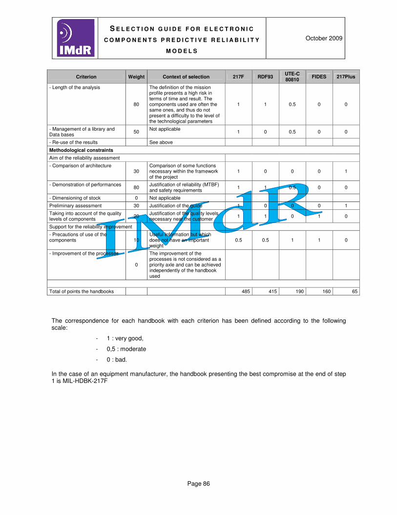
S E L E C T I O N G U I D E F O R E L E C T R O N I C
C O M P O N E N T S P R E D I C T I V E R E L I A B I L I T Y
M O D E L S
October 2009
Page 86
Criterion Weight Context of selection 217F RDF93 UTE-C 80810
FIDES 217Plus
- Length of the analysis
80
The definition of the mission profile presents a high risk in terms of time and result. The components used are often the same ones, and thus do not present a difficulty to the level of the technological parameters
1 1 0.5 0 0
- Management of a library and Data bases
50 Not applicable
1 0 0.5 0 0
- Re-use of the results See above
Methodological constraints
Aim of the reliability assessment
- Comparison of architecture 30
Comparison of some functions necessary within the framework of the project
1 0 0 0 1
- Demonstration of performances
80 Justification of reliability (MTBF) and safety requirements
1 1 0.5 0 0
- Dimensioning of stock 0 Not applicable
Preliminary assessment 30 Justification of the guide 1 0 0 0 1
Taking into account of the quality levels of components
20 Justification of the quality levels necessary near the customer
1 1 0 1 0
Support for the reliability improvement
- Precautions of use of the components 10
Useful information but which does not have an important weight
0.5 0.5 1 1 0
- Improvement of the processes
0
The improvement of the processes is not considered as a priority axle and can be achieved independently of the handbook used
Total of points the handbooks 485 415 190 160 65
The correspondence for each handbook with each criterion has been defined according to the following scale:
- 1 : very good,
- 0,5 : moderate
- 0 : bad.
In the case of an equipment manufacturer, the handbook presenting the best compromise at the end of step 1 is MIL-HDBK-217F

S E L E C T I O N G U I D E F O R E L E C T R O N I C
C O M P O N E N T S P R E D I C T I V E R E L I A B I L I T Y
M O D E L S
October 2009
Page 87
Step 2 : Analysis of the overall limits of the handbooks
Overall limits Context of analysis 217F RDF93 UTE-C 80810
FIDES 217Plus
Modelling of the non operating phase Non operating phases are not the most important ones and their modelling is not a priority
0.5 0.5
Early failures period taken into account It is not necessary to model the reliability during early failures period
1 1 1
Influence of the modelling of the thermal cycling
0.5 1
Sensitivity with the assomptions 0.5
Induced stresses 1 1
Modelling of complex environments 0.5
Implicit consideration of a policy of monitoring and improvement of the product
1
Influence of the process modelling on the failure rate of components
1
Product of the notation limits 0.5 0.5 0.5 0.5 0.5
Marks from step 1 485 415 190 160 65
Total 243 208 95 80 33
For each handbook it's compatibility with each limit has been quantified according to the following scale:
- 1 : compatible / acceptable limit,
- 0,5 : limit moderately acceptable
- 0 : un compatible limit.
In the case of a equipment manufacturer, the handbook presenting the best compromise at the end of step 2 is still MIL-HDBK-217F, This handbook is chosen as reference handbook

S E L E C T I O N G U I D E F O R E L E C T R O N I C
C O M P O N E N T S P R E D I C T I V E R E L I A B I L I T Y
M O D E L S
October 2009
Page 88
Stage 3: Identification of the recommendations/solutions compared to the operational requirements for the reference handbook
MIL-HDBK-217 reference Handbook
Operational requirements Recommendation of the
guide Acceptable? Justification Alternative solution
Passive components
Absence of modelling of the variable capacitors FEP, Knell, Mica, Paper
To use the values “leaves count” the general capacitor of the 217Plus
Yes This kind of components is not used in the equipment
Absence of modelling of the capacitors vacuum
To use the values “leaves count” the general capacitor of the 217Plus
N/A This kind of components is not used in the equipment
Parameters of the capacitors aluminium to liquid electrolyte
To take into account the additional workload linked with the assessment of the parameters associated with these components
N/A This kind of components is not used in the equipment
Negative temperatures To use the mocks up are equivalent of theUTE-C 80810, FIDES or 217Plus handbooks
N/A The equipment is not subjected to negative temperatures
Discrete active components
No the specific constraint with this family
-
Integrated components
Absence of modelling of the mixed integrated circuits
To use the mock up of the linear circuits if a pessimistic modelling can be appropriate. If not, to use another handbook for these components.
Yes
Absence of modelling of the integrated circuits with case BGA
To use the mock up of cases QFP if a pessimistic modelling can be appropriate. If not, to use another handbook for the circuits with this kind of box.
Yes
Parameters of the mock up of memories EEPROM and circuits VHSIC
To use default values for components for the parameters unavailable if these components do not have a significant contribution on the reliability. If not, to take into account the additional workload linked with research and the identification of the parameters like with their validation.
Yes These components are used little. The adverbial phrase of time for the identification of the associated parameters is not problematic

S E L E C T I O N G U I D E F O R E L E C T R O N I C
C O M P O N E N T S P R E D I C T I V E R E L I A B I L I T Y
M O D E L S
October 2009
Page 89
MIL-HDBK-217 reference Handbook
Operational requirements Recommendation of the
guide Acceptable? Justification Alternative solution
Old of the components Preferentially to use the FIDES and 217Plus handbooks are recommended for recent components, the UTE-C 80810 hanbook for components dating from the 90s, and MIL-HDBK-217 and RDF93 handbooks for components of the 80s.
Yes
Technical limits of the modelized components
To use the mocks up with their level of maximum complexity if a conservative approach is possible, if not to use another handbook for the integrated circuits beyond the limits of handbook MIL-HDBK-217
Yes/Not If the important number of circuits what can induce a unacceptable error
The mocks up of the UTE-C 80810 or FIDES handbooks can be used if the results need to be refined
Hybrid components
Support and components deposited
To use theRDF93 and UTE-C 80810 handbooks if the support and the components deposited are known to have a significant influence on the reliability of the hybrid circuit
N/A This kind of components is not used in the equipment
Taking into account of the quality of components of the hybrid circuit
To use RDF93 handbook if it is necessary to be able to take into account the influence of the quality of components on the total reliability of the hybrid circuit
N/A This kind of components is not used in the equipment
Electromechanical components
Absence of modelling of the elastomeric connectors
To use the mock up of the rectangular connectors with a degraded failure rate of a factor 5 if a pessimistic approach is possible
N/A This kind of components is not used in the equipment
Absence of modelling of the printed circuit boards
To use the handbook such as it was envisaged without modeling the printed circuit boards
Yes
Negative temperatures To use the mocks up are equivalent of the UTE-C 80810, FIDES or 217Plus handbooks
N/A The equipment is not subjected to negative temperatures
Other components
N/A
There exists a solution for each operational requirement of the MIL-HDBK-217 handbook.

S E L E C T I O N G U I D E F O R E L E C T R O N I C
C O M P O N E N T S P R E D I C T I V E R E L I A B I L I T Y
M O D E L S
October 2009
Page 90
Stage 4: Constitution of the baseline to be implemented
The provisional assessments of reliability will be achieved starting from the Mil-HDBK-217 handbook the following rules of use:
- Use of the values manufacturer or “share count” of the variable capacitor of the 217Plus handbook for the variable capacitors FEP, Knell, Mica, Paper
- the mixed integrated circuits are considered as linear circuits having the same parameters,
- Boxes BGA are considered as cases QFP,
- The integrated circuits having a level of complexity greater than the limits indicated will be modelled by using the high limits of the mocks up if their number and their contribution to the total reliability are acceptable. In the opposite case, the mocks up of FIDES or UTE-C 80810 handbooks will be used.
- The printed circuit board is not modelled.
1.1.1. EXAMPLE 2
The example below considers the case of a customer of the sector space systems wishing to define a baseline of reliability calculation in the case of a satellite (orbital life phase) in sight constellation (15 satellites envisaged but different electric architectures of the equipment items). The environment is similar between the satellites similar life profile with much of thermal cycles and ON/OFF.
Step 1: Reference handbooks classification
Criteria Ref. Weigh
t Context of selection 217F RDF93
UTE-C 80810
FIDES 217Plus
Contextual stresses
Adequacy of the experience feedback
§ 3.1.1.1
10
Space systems (aeronautical equivalent civil /military)
1 0 1 1 0
Modelling of the environment § 3.1.1.2
80
Parameter setting of the life profile, stresses of thermal cycles
0 0 1 1 1
Operational stresses
Re-use of the results § 3.1.2.1
50
Identical environment, equipment manufacturers qualified ASF for space systems (thus pi known process FIDES)
1 1 1 1 0
Smoothness of the modellings § 3.1.2.2 20
Fides presents the best level of smoothness 0 0 0 1 0

S E L E C T I O N G U I D E F O R E L E C T R O N I C
C O M P O N E N T S P R E D I C T I V E R E L I A B I L I T Y
M O D E L S
October 2009
Page 91
Criteria Ref. Weigh
t Context of selection 217F RDF93
UTE-C 80810
FIDES 217Plus
Taking into account of the influences development processes/manufacturing
for the customers § 3.1.2.3 0
Taken into account in approvals ASF 0 0 0 0 0
for the suppliers § 3.1.2.3 0
Taken into account in approvals ASF 0 0 0 0 0
Cost/schedule/difficulty
Acquisition of the handbook § 3.1.2.4 0 Unapplicable 0 0 0 0 0
Operating tools § 3.1.2.4 0 Unapplicable 0 0 0 0 0
Training/appropriation of methodologies of the handbook
§ 3.1.2.4 0
Unapplicable 0 0 0 0 0
Time of achievement of the analysis
§ 3.1.2.4 0
Unapplicable 0 0 0 0 0
Management of a library and Data bases
§ 3.1.2.4 0
Unapplicable 0 0 0 0 0
Re-use of the results § 3.1.2.4 0
See operational stresses 0 0 0 0 0
Methodological stresses
Aim of the assessment of reliability
Comparison of architecture § 3.1.3.1 100 1 1 1 1 0
Demonstration of performances § 3.1.3.1 30 Breakdown by phase 1 1 1 1 0
Assessment of stocks § 3.1.3.1 0 0 0 0 0 0
Assessment upstream preliminary § 3.1.3.2 50 1 0 0 0 1
Taking into account of the quality level of the components
§ 3.1.3.3 80
1 1 0 1 0
Support for the reliability improvement
Precautions of use of the components
§ 3.1.3.4 10
Taken into account in approvals ASF 0 0 1 1 0
Improvement of the processes § 3.1.3.4 0
Taken into account in approvals ASF 0 0 0 0 0
Total of points of the handbooks 430 320 260 280 380 130
The MIL-HDBK-217, UTE-C 80810 and FIDES handbooks are selected for the analysis of the limits.

S E L E C T I O N G U I D E F O R E L E C T R O N I C
C O M P O N E N T S P R E D I C T I V E R E L I A B I L I T Y
M O D E L S
October 2009
Page 92
Step 2: Global limits analyses of the handbooks
Total limits Context of analysis 217F RDF93 UTE-C 80810 FIDES 217Plus
Modelling of failure no the non-operation period 1 NA
Taking into account of the periods of youth
No the requirement: screening of components
1 NA 1
Influence the modelling of the thermal cycles
Strong stress REJECTION NA
Sensitivity with the assumptions
Information on the environment does not make it possible to inform the mission profile without making assumptions requiring a study of sensitivity: made study
1
Induced stresses UTE-C 80810: The equipment items in general have many electric interfaces with associated protections
1 NA
Modelling of complex environments
It is not necessary to model complex environments
NA
Taking into account of a policy of monitoring and reliability improvement
It is possible to set up a policy of monitoring and reliability improvement
NA
Influence modelling of the process on failure rate
The influence of the processes will be modeliled by using the default values proposed in the handbooks
NA
Product of the limits 1 0 0 1 0
Notes of stage 1 320 260 280 380 130
Total 320 0 0 380 0
In the case of this customer, the handbook which presents the best compromise at the end of the first step is FIDES.
Step 3: Identification of the recommendations/solutions compared to the operational requirements of the reference handbook
The technological stresses are not known (not list of components) apart from the integrated components (new technologies with strong integration) for which the FIDES handbook is recommended to the MIL-HDBK-217handbook.
It is thus not achieved a complete analysis of this stage.
Step 4: Constitution of the baseline to be implemented
The provisional assessments of reliability will be achieved starting from the FIDES handbook: