Selection and Performance - Power Transmission … · Principal application ar-eas of rigid...
10
00 powertransmissionengineering october 2008 www.powertransmission.com 2 2 0 2 00 Introduction Power transmission couplings are widely used for modification of stiffness and damping in power transmission systems, both in torsion and in other directions (misalignment compensa- tion). Technical literature on connect- ing couplings is scarce and is dominated by trade publications and commercial coupling catalogs. Many coupling de- signs use elastomers in complex load- Selection and Performance CRITERIA FOR POWER TRANSMISSION COUPLINGS— PART I Eugene I. Rivin compared to the machines it connects, is a critical aspect of any shaft system, and a good deal of attention must be paid to its choice at the design stage.” —from the Resolution of the First International Conference on Flexible Couplings ing modes; some couplings have joints with limited travel distances between the joint components accommodated by friction; often, couplings have severe limitations on size and rotational inertia, etc. ese factors make a good coupling design a very difficult task, which can be helped by a clearer understanding of the coupling’s functions. Stiffness values of couplings in both torsional and mis- alignment directions, as well as damping
Transcript of Selection and Performance - Power Transmission … · Principal application ar-eas of rigid...
00 powertransmissionengineering october 2008 www.powertransmission.com 2200200200200
IntroductionPower transmission couplings are
widely used for modifi cation of stiff ness and damping in power transmission systems, both in torsion and in other directions (misalignment compensa-tion). Technical literature on connect-ing couplings is scarce and is dominated by trade publications and commercial coupling catalogs. Many coupling de-signs use elastomers in complex load-
Selection and
Performance CRITERIA FOR POWER
TRANSMISSION COUPLINGS—
PART IEugene I. Rivin
“A flexible coupling, although it is relatively small and cheap compared to the machines it connects, is a critical aspect of any shaft system, and a good deal of attention must be paid to its choice at the design stage.” —from the Resolution of the First International Conference on Flexible Couplings
ing modes; some couplings have joints with limited travel distances between the joint components accommodated by friction; often, couplings have severe limitations on size and rotational inertia, etc. Th ese factors make a good coupling design a very diffi cult task, which can be helped by a clearer understanding of the coupling’s functions. Stiff ness values of couplings in both torsional and mis-alignment directions, as well as damping

www.powertransmission.com october 2008 powertransmissionengineering 211221221321321
continued
Figure 1. (Editor’s note: AGMA 510.02 has been superseded by ANSI/AGMA 9009 - D02- Nomenclature for Flexible Cou-plings, and the newer standard uses slight-ly diff rent terminology. Th e older version is used here for illustrative purposes.) If the misaligned shafts are rigidly connected, this leads to their elastic deformations, and thus to dynamic loads on bear-ings, to vibrations, to increased friction losses, and to unwanted friction forces in servo-controlled systems. Purely misalignment-compensating couplings have torsional deformations and mis-alignment-compensating deformations decoupled from movements associated with misalignments.
3. Torsionally Flexible Couplings.
of couplings in the torsional direction, have a substantial, often determining, eff ect on the drive system dynamics. Torsionally fl exible couplings are often used for tuning dynamic characteristics (natural frequencies and/or damping) of the drive/transmission by intentional change of their stiff ness and damping.
Th e purpose of this article is to dis-tinctly formulate various couplings’ roles in machine transmissions, as well as to formulate criteria for comparative as-sessment, optimization and selection of coupling designs. To achieve these goals, a classifi cation of connecting cou-plings is given and comparative analyses of commercially available couplings are proposed.
General Classifi cation of CouplingsAccording to their role in transmis-
sions, couplings can be divided into four classes:
1. Rigid Couplings. Th ese couplings are used for rigid connection of pre-cisely aligned shafts. Besides the torque, they also transmit bending moments and shear forces if any misalignment is present, as well as axial force. Th e bending moments and shear forces may cause substantial extra loading of the shaft bearings. Principal application ar-eas of rigid couplings are: long shafting; space constraints preventing use of mis-alignment-compensating or torsionally fl exible couplings; and inadequate dura-bility and/or reliability of other types of couplings.
2. Misalignment-Compensating Cou-plings. Th ese are required for connecting two members of a power transmission or motion transmission system that are not perfectly aligned. “Misalignment” means that components—coaxial by de-sign—are not actually coaxial, due either to assembly errors or to deformations of subunits and/or foundations. Th e latter factor can be of substantial importance for large turbine installations (thermal/creep deformations leading to drastic load redistribution between the bear-ings) and for power transmission sys-tems on non-rigid foundations (such as ship propulsion systems). Various types of misalignment as they are defi ned in AGMA standard 510.02 are shown in
Such couplings are used to change dy-namic characteristics (natural frequency, damping and character/degree of non-linearity) of a transmission system. Th e changes are desirable or necessary when severe torsional vibrations are likely to develop in the transmission system, leading to dynamic overloads. Designs of torsionally fl exible couplings usually are not conducive to compensating mis-alignments.
4. Combination Purpose Cou-plings. Th ese combine signifi cant com-pensating ability with signifi cant tor-sional fl exibility. Th e majority of the commercially available connecting cou-plings belong to this group. Since the torsional deformations and deforma-
Nomenclature
D External diameter
d Internal diameter
L Length
Fcom
Radial force, or bending moment
Ft
Tangential force
Ref
Effective radius
T Transmitted torque
µ Friction coefficient
k Stiffness factor
kcom
Combined stiffness of elastic connectors
E Radial misalignment
Dp
Pitch Diameter
θ Angular misalignment
Leq
Sound pressure level
η Efficiency
ksh
ksh
k Shear stiffness
ψ Relative energy displacement
V Potential energy
Pt
Tangential force
W Energy per coupling revolution
β Loss factor of rubber

00 powertransmissionengineering october 2008 www.powertransmission.com 24002400
A L I G N M E N T
Y
P A R A L L E L O F F S E T M I S A L I G N M E N T
A = B
A B
�
SYMMETRICAL ANGULAR MISALIGNMENT
A > B
A B
�
NON-SYMMETRICAL ANGULAR MISALIGNMENT
�
Y
COMBINED ANGULAR-OFFSET MISALIGNMENT
Figure 1— Types of coupling misalignment.
tions due to misalignments are not sep-arated/decoupled by design, changes in torsional stiff ness may result in changes in misalignment-compensating stiff -ness, and vice versa. Th ese couplings will be discussed in detail in Part II of this article, which will appear next issue.
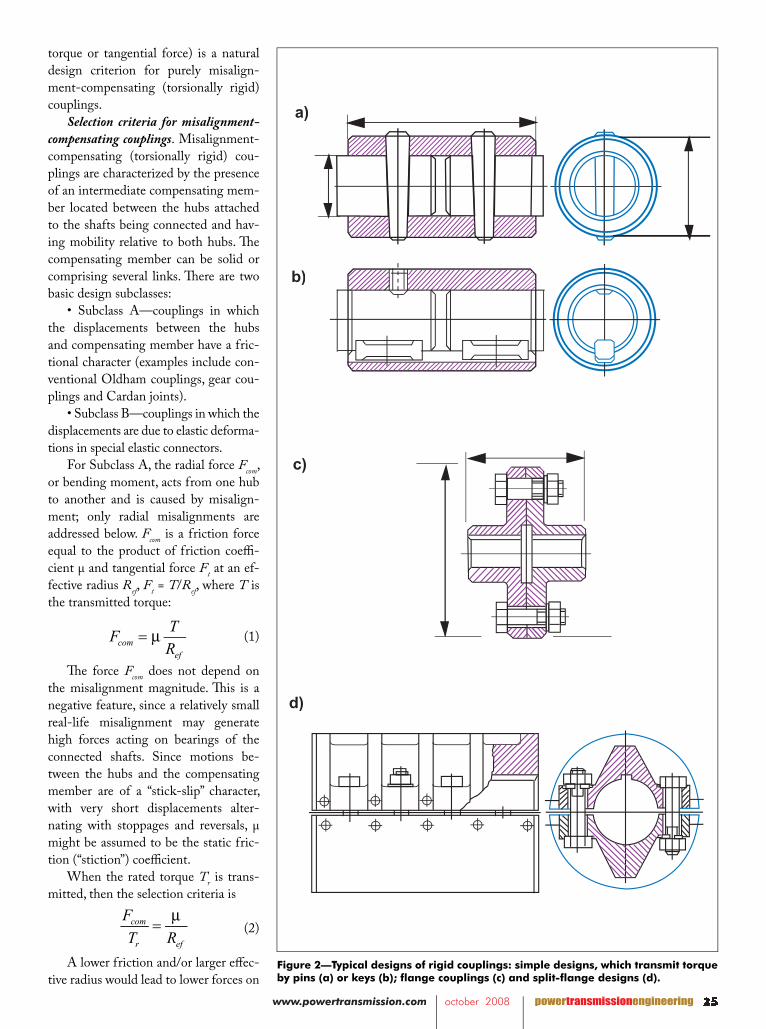
Rigid CouplingsTypical designs of rigid couplings
are shown in Figure 2.Sleeve couplings as in Figures 2a
and 2b are the simplest and the slim-mest ones. Such a coupling transmits
torque by pins (Fig. 2a) or by keys (Fig. 2b). Th e couplings are diffi cult to as-semble/disassemble, as they require sig-nifi cant axial shifting of the shafts to be connected/disconnected. Usually, exter-nal diameter D = (1.5–1.8) d, and length L = (2.5–4.0) d.
Flange couplings (Fig. 2c) are the most widely used rigid couplings. Two fl anges have machined (reamed) holes for precisely machined bolts inserted into the holes without clearance (no backlash). Th e torque is transmitted by
friction between the contact surfaces of the fl anges and by shear resistance of the bolts. Usually, D = (3–5.5) d, and L= (2.5–4.0) d.
A split-sleeve coupling (Fig. 2d) transmits torque by friction between the half-sleeves and the shafts and, in some cases, also by a key. Th eir main advan-tage is ease of assembly/disassembly.
Misalignment-Compensating Couplings
Misalignment-compensating cou-plings are used to radically reduce the eff ects of imperfect alignment by allow-ing a non-restricted or a partially re-stricted motion between the connected shaft ends in the radial and/or angular directions. Similar coupling designs are sometimes used to change bending nat-ural frequencies/modes of long shafts. When only misalignment compensa-tion is required, high torsional rigid-ity and, especially, absence of backlash in the torsional direction, are usually positive factors, preventing distortion of dynamic characteristics of the transmis-sion system. Th e torsional rigidity and absence of backlash are especially im-portant in servo-controlled systems.
To achieve high torsional rigidity together with high compliance in mis-alignment directions (radial or parallel off set, axial, angular), torsional and mis-alignment-compensating displacements in the coupling have to be separated by using an intermediate compensat-ing member. Typical torsionally rigid, misalignment-compensating couplings are Oldham couplings, which compen-sate for radial misalignments (Fig. 3a); gear couplings, which compensate for small angular misalignments (Fig. 3b); and universal or Cardan joints, which compensate for large angular misalign-ments (Fig. 3c). Frequently, torsion-ally rigid “misalignment-compensat-ing” couplings, such as gear couplings, are referred to in the trade literature as “fl exible” couplings.
Usually, transmissions designed for greater payloads can tolerate higher misalignment-induced loads. Accord-ingly, the ratio between the load gener-ated in the basic misalignment direction (radial or angular) to the payload (rated
www.powertransmission.com october 2008 powertransmissionengineering 21
torque or tangential force) is a natural design criterion for purely misalign-ment-compensating (torsionally rigid) couplings.
Selection criteria for misalignment-compensating couplings. Misalignment-compensating (torsionally rigid) cou-plings are characterized by the presence of an intermediate compensating mem-ber located between the hubs attached to the shafts being connected and hav-ing mobility relative to both hubs. Th e compensating member can be solid or comprising several links. Th ere are two basic design subclasses:
• Subclass A—couplings in which the displacements between the hubs and compensating member have a fric-tional character (examples include con-ventional Oldham couplings, gear cou-plings and Cardan joints).
• Subclass B—couplings in which the displacements are due to elastic deforma-tions in special elastic connectors.
For Subclass A, the radial force Fcom, or bending moment, acts from one hub to another and is caused by misalign-ment; only radial misalignments are addressed below. Fcom is a friction force equal to the product of friction coeffi -cient µ and tangential force Ft at an ef-fective radius Ref, Ft = T/Ref, where T is the transmitted torque:
(1)
Th e force Fcom does not depend on the misalignment magnitude. Th is is a negative feature, since a relatively small real-life misalignment may generate high forces acting on bearings of the connected shafts. Since motions be-tween the hubs and the compensating member are of a “stick-slip” character, with very short displacements alter-nating with stoppages and reversals, µ might be assumed to be the static fric-tion (“stiction”) coeffi cient.
When the rated torque Tr is trans-mitted, then the selection criteria is
(2)
A lower friction and/or larger eff ec-tive radius would lead to lower forces on
125212521
A L I G N M E N T
Y
P A R A L L E L O F F S E T M I S A L I G N M E N T
A = B
A B
�
SYMMETRICAL ANGULAR MISALIGNMENT
A > B
A B
�
NON-SYMMETRICAL ANGULAR MISALIGNMENT
�
Y
COMBINED ANGULAR-OFFSET MISALIGNMENT
Figure 2—Typical designs of rigid couplings: simple designs, which transmit torque by pins (a) or keys (b); flange couplings (c) and split-flange designs (d).
a)
b)
c)
d)
com
r ef
F
T R
µ=
comef
TF
Rµ=

00 powertransmissionengineering october 2008 www.powertransmission.com
the bearings.For Subclass B, assuming linearity
of the elastic connectors,
(3)
Where e = radial misalignment val-ue, and kcom = combined stiff ness of the elastic connectors in the radial direction. In this case,
(4)
Unlike the Subclass A couplings, Subclass B couplings develop the same radial force for a given misalignment, regardless of the transmitted torque; thus they are more eff ective for large Tr. Of course, a lower stiff ness of the elastic connectors would lead to lower radial forces.
Conventional Oldham couplings, gear couplings and u-joints (Subclass A). Mis-alignment-compensating couplings are used in cases where a signifi cant torsional compliance can be an undesirable factor and/or a precise alignment of the con-nected shafts cannot be achieved. Univer-sal joints (u-joints or Cardan joints) are used in cases where the dominant type of shaft misalignment is angular misalign-ment. Use of a single joint results in a non-uniform rotation of the driven shaft, which can be avoided by using double joints or specially designed “constant ve-locity” joints. Compensation of a radial misalignment requires using two Cardan joints and relatively long intermediate shafts. If bearings of the u-joint are not preloaded, the joint has an undesirable backlash, but preloading of the bearings increases frictional losses and reduces ef-fi ciency. More sophisticated linkage cou-plings are not frequently used, due to the specifi c characteristics of general-purpose machinery, such as limited space, limited amount of misalignment to compensate for, and cost considerations.
While u-joints use sliding or roll-ing (needle) bearings, both Oldham and gear couplings compensate for mis-alignment of connected shafts by means of limited sliding between the hub sur-faces and their counterpart surfaces on the intermediate member. Th e sliding
26002600
Y X
c (D-e)
P
(D-e)
e
P
D
a)
(D-e)
e
P
D
b)
P
SPIDER TRUNNIONYOKEYOKE
YOKE
a
1
a
b
3
2
d
101
106
103a108a
105
111 112
108b
103b
107
102
125
118
a)
b)
c)
Figure 3—Torsionally rigid, misalignment-compensating couplings: Oldham couplings (a), gear couplings (b) and universal joints or Cardan joints (c).
1ef
TF
Rµ=1
ef
TF
Rµ=1
ef
TF
Rµ=
Y X
c (D-e)
P
(D-e)
e
P
D
a)
(D-e)
e
P
D
b)
P
SPIDER TRUNNIONYOKEYOKE
YOKE
a
1
a
b
3
2
d
101
106
103a108a
105
111 112
108b
103b
107
102
125
118
Y X
c (D-e)
P
(D-e)
e
P
D
a)
(D-e)
e
P
D
b)
P
SPIDER TRUNNIONYOKEYOKE
YOKE
a
1
a
b
3
2
d
101
106
103a108a
105
111 112
108b
103b
107
102
125
118
Fcom
= kcom
e
com com
r r
F ke
T T=

www.powertransmission.com october 2008 powertransmissionengineering 2127212721
continued
Y X
c (D-e)
P
(D-e)
e
P
D
a)
(D-e)
e
P
D
b)
P
SPIDER TRUNNIONYOKEYOKE
YOKE
a
1
a
b
3
2
d
101
106
103a108a
105
111 112
108b
103b
107
102
125
118
Y X
c (D-e)
P
(D-e)
e
P
D
a)
(D-e)
e
P
D
b)
P
SPIDER TRUNNIONYOKEYOKE
YOKE
a
1
a
b
3
2
d
101
106
103a108a
105
111 112
108b
103b
107
102
125
118
Figure 4—Stress distribution between the contacting surfaces a and b of hub and intermediate member of the Oldham coupling shown in Figure 3a, assembled without clearance (a) and with clearance (b).
Figure 6—A torsionally rigid, misalignment-compensating coupling.
Figure 5—Kudriavetz coupling.
has a cyclical character, with double am-plitude of displacement equal to radial misalignment e for an Oldham coupling and Dpθ for a gear coupling (Ref. 5), where Dp is the pitch diameter of the gears and θ is the angular misalign-ment. If a radial misalignment e has to be compensated by gear couplings, then two gear couplings spaced by distance L are required, and θ = e/L. Such a motion pattern is not conducive to good lubri-cation, since at the ends of the relative travel, where the sliding velocity is zero, a metal-to-metal contact is very prob-able. Th e stoppages are associated with increasing friction coeffi cients, close to the static friction values. Th is is the case for low-speed gear couplings and for Oldham couplings; for high-speed gear couplings, the high lubricant pressure due to centrifugal forces alleviates the problem (Ref. 5).
Figure 3a shows a compensating (Oldham) coupling, which—at least theoretically—allows the connection of shafts with a parallel misalignment between their axes without induc-ing nonuniformity of rotation of the driven shaft and without exerting high loads on the shaft bearings. Th e cou-pling comprises two hubs, (1) and (2), connected to the respective shafts and an intermediate disc (3). Th e torque is transmitted between driving member (1) and intermediate member (3), and between intermediate member (3) and driven member (2), by means of two orthogonal sliding connections, a-b and c-d. By decomposition of the mis-alignment vector into two orthogonal components, this coupling theoretically assures ideal radial compensation while being torsionally rigid. Th e latter feature may also lead to high torque-to-weight ratios. However, this ingenious design fi nds only an infrequent use, usually for noncritical, low-speed applications. Some reasons for this are as follows.
For the Oldham coupling, radial force from one side of the coupling (one hub-to-intermediate member connec-tion) is a rotating vector aimed in the direction of the misalignment and with the magnitude

00 powertransmissionengineering october 2008 www.powertransmission.com
(5)
whose direction reverses abruptly twice during a revolution. Th e other side of the coupling generates another radial force of the same amplitude, but shifted 90 degrees. Accordingly, the amplitude of the resultant force is
(6)
Its direction changes abruptly four times per revolution. Similar eff ects oc-cur in gear couplings. An experimental Oldham coupling (Tr = 150 N-m, exter-nal diameter Dex = 0.12 m, e = 1 mm and n = 1,450 rpm) exerted radial force on the connected shafts Fcom = 720 N.
Th e frequent stoppages and direc-tion reversals of the forces lead to the high noise levels generated by Oldham and gear couplings. A gear coupling can be the noisiest component of a large power-generation system (Ref. 6). A sound pressure level Leq = 96 dBA was measured at the experimental Oldham coupling described above.
Since a clearance is needed for normal functioning of the sliding con-nections, the contact stresses are non-uniform with high peak values (Fig.
rial (usually heat-treated steel) since the same material is used both for the hub and the intermediate disc structures and for the sliding connections. Friction can be reduced by making the intermedi-ate member from a low-friction plastic, such as ultra-high molecular weight (UHMW) polyethylene, but this may result in a reduced rating due to lowered structural strength.
Because of high misalignment-compensating forces, deformations of the coupling assembly itself can be very substantial. If the deformations become equal to the shafts’ misalignment, then no sliding will occur and the coupling behaves as a solid structure, being ce-mented by static friction forces. It can happen at misalignments below e ≈ 10-3Dex. Th is eff ect seems to be one of the reasons for the trend toward replacing misalignment-compensating couplings by rigid couplings, such as the rigid fl ange coupling in Figure 1c, often used in power generating systems.
Due to internal sliding with high friction, Oldham and gear couplings demonstrate noticeable energy losses. Th e effi ciency of an Oldham coupling for e/Dex ≤ 0.04 is
(7)
For µ = 0.4 and e = 0.01Dex, η = 0.987 and for µ = 0.3, η = 0.99. Similar (slightly better due to better lubrication) effi ciency is characteristic for single-gear couplings.
Th is inevitable backlash in the gear and Oldham connections is highly un-desirable for servo-controlled transmis-sions.
Oldham couplings and u-joints with elastic connections (Subclass B). Th e basic disadvantages of conventional Oldham and gear couplings (high radial forces, jumps in the radial force direction, en-ergy losses, backlash, nonperformance at small misalignments, noise) are all associated with reciprocal, short travel, poorly lubricated sliding motion be-tween the connected components. Th ere are several known techniques of chang-ing friction conditions. Rolling friction bearings in u-joints greatly reduce fric-
28002800 28 6
Figure 7—A large u-joint with thin-layered, rubber-metal bearings.
39
33
4437
3831
32
41
40
35
4334
35
6
7
9
11
7 10
6
10
1 3.2ex
e
Dη µ= −
2ref
TF
Rµ=
1ef
TF
Rµ= 4). Figure 4a shows stress distribution
between the contacting surfaces a and b of hub (1) and intermediate member (3) of the Oldham coupling shown in Fig-ure 3a assembled without clearance. Th e contact pressure in each contact area is distributed in a triangular mode along the length 0.5(D – e) ≈ 0.5D. However, the clearance is necessary during assem-bly, and it increases due to inevitable wear of the contact surfaces. Presence of the clearance changes the contact area as shown in Figure 4b, so that the contact length is l ≈ 0.3(D – e) ≈ 0.3D (or the contact length is 0.5c(D – e), c ≈ 0.68), thus signifi cantly increasing the peak contact pressures and further increasing the wear rate. Th is leads to a rapid increase of the backlash, unless the initial (design) contact pressures are greatly reduced. Such non-uniform contact loading also results in very poor lubrication conditions in the stick-slip motion. As a result, friction coeffi cients in gear and Oldham couplings are quite high, especially in the latter.
Experimental data for gear cou-plings show µ = 0.3–0.4. Similar friction coeffi cients are typical for Oldham cou-plings. Th e coupling components must be made from a wear-resistant mate-

www.powertransmission.com october 2008 powertransmissionengineering 21
and energy dissipated per cycle of de-formation is
(9)
Each of the two connections experi-ences two deformation cycles per revo-lution; thus the total energy dissipated per revolution of the coupling is
(10)
Total energy transmitted through the coupling per revolution is equal to
(11)
where Pt = T/Dex is tangential force re-ex is tangential force re-exduced to the external diameter Dex and T is the transmitted torque. Effi ciency T is the transmitted torque. Effi ciency Tof a coupling is therefore equal to
(12)
where β is the loss factor of the rubber.For the experimentally tested cou-
pling (Dex = 0.12 m), the parameters are: ex = 0.12 m), the parameters are: exa laminate with rubber layers 2 mm in thickness; ψ = 0.2; ksh = 1.8 x 10⁵ N/m; T= 150 N-m; T= 150 N-m; T e = 0.001 m; thus e = 0.001 m; thus e η = 1 – (0.2 x 1.8 x 105 x 10-6)/150π = 1 – 0.75 x 10-4 = 0.999925, or the losses at full torque are reduced 200 times as compared to the conventional coupling.
Test results for the conventional and modifi ed Oldham couplings having Dex= 0.12 m have shown that the maxi-mum transmitted torque was the same, but there was a 3.5 times reduction in the radial force transmitted to the shaft bearings with a modifi ed coupling. Ac-tually, the coupling showed the lowest radial force for a given misalignment compared with any commercially avail-able compensating coupling, including couplings with rubber elements. In ad-dition to this, the noise level at the cou-pling was reduced by 13 dBA to Leq = 83 dBA. Using ultra thin-layered laminates for the same coupling would further increase its rating by at least one order
129212921
continued
2 2tan1 1 1sh shk kV
e eW T T
ψ βη
π∆
= − = − = −
2 2tan1 1 1sh shk kV
e eW T T
ψ βη
π∆
= − = − = −
2
1 2sh
eV k=
∆V = 2V = 2V ∆ = 2∆ = 2 V1 = 2ψ = 2ψ = 2 kshe
kshe
k 2
W =PtπD
ex = 2πT T T
2
1 2sh
eV kψ∆ =
tion forces. However, they do not per-form well for small-amplitude recipro-cal motions. In many applications, shafts connected by u-joints are installed with an artifi cial 2–3° initial misalignment to prevent jamming of the rolling bodies.
Another possible option is using hy-drostatic lubrication. Th is technique is widely used for rectilinear guide ways, journal and thrust bearings, screw and worm mechanisms, etc. However, this technique seems impractical for rotat-ing systems with high loading intensity (and thus high required oil pressures).
Replacement of sliding and rolling friction by elastically deformable con-nections can resolve the above problems. Figure 5 shows a “K” or “Kudriavetz” coupling made from a strong, fl exible material (polyurethane) connected with the hubs by two “tongues” each. If the connected shafts have a radial off set, it is compensated by bending of the tongues, thus behaving like an Oldham coupling with elastic connections between the intermediate member and the hubs. If the connected shafts each have an an-gular misalignment, the middle mem-brane behaves as a “cross,” while twist-ing deformations of the tongues create kinematics of a u-joint. As a result, this coupling can compensate large radial misalignments (∼2.4 mm for a coupling with external diameter of D = 55 mm), D = 55 mm), Das well as angular misalignments of ±10 degrees. Th e torque ratings of such cou-plings are obviously quite low; e.g., a coupling with outside diameter D = 55 D = 55 Dmm has a rated torque Tr = 4.5 N-m.
Since displacements in the sliding connections a-b and c-d in Figure 3a are small (equal to the magnitude of the shaft misalignment), the Oldham cou-pling is a good candidate for application of the thin-layered rubber metal lami-nates (Ref. 1). Some of the advantages of using laminates are their very high compressive strength, up to 100,000 psi (700 MPa), and insensitivity of their shear stiff ness to the compressive force. Th is property allows the preloading of the fl exible element without increasing deformation losses.
Figure 6 (from Ref. 2) shows such an application. Hubs 101 and 102 have
slots 106 and 107, respectively, whose axes are orthogonal. Th e intermediate disc can be assembled from two iden-tical halves 103a and 103b. Slots 108a and 108b in the respective halves are also orthogonally oriented. Holders 105 are fastened to slots 108 in the interme-diate disc and are connected to slots 106 and 107 via thin-layered rubber-metal laminated elements 111 and 112 as de-tailed in Figure 6b. Th ese elements are preloaded by sides 125 of holders 105, which spread out by moving preloading roller 118 radially toward the center.
Th is design provides for all kine-matic advantages of the Oldham cou-pling without creating the above-listed problems associated with conventional Oldham couplings. Th e backlash is to-tally eliminated since the coupling is preloaded. For the same rated torque, the coupling is much smaller than the conventional one due to the high load-carrying capacity of the laminates and the absence of stress concentrations like ones shown in Figure 4b. Th e interme-diate disc (the heaviest part of the cou-pling) can be made from a light, strong material, such as aluminum, since it is not exposed to contact loading. Th is makes the coupling suitable for high-speed applications.
Th e misalignment compensation stiff ness and the rated torque can be varied by proportioning the laminated elements (their overall dimensions, thickness and number of rubber layers, etc.). Th e loads on the connected shafts are greatly reduced and are not depen-dent on the transmitted torque since the shear stiff ness of the laminate does not depend on the compression load.
To derive an expression for effi cien-cy of the Oldham coupling with lami-nated connections, let the shear stiff ness of the connection between one hub and the intermediate member be denoted by ksh and the relative energy dissipation in the rubber for one cycle of shear defor-mation by ψ. Th en, maximum potential energy in the connection (at maximum shear e) is equal to
(8)

00 powertransmissionengineering october 2008 www.powertransmission.com
the elastomeric bearing sleeve. To per-form assembly operation, the tapered bearing sleeve is inserted into the wider opening of the tapered annular space between the internal surface of the bore and the external surface of the trunnion and pressed into this space by a punch shaped to contact simultaneously both end surfaces. Wedge action of the ta-pered connection between the conform-ing inner surface of metal layer 40 and outer surface of trunnion33 results in expansion of metal layer 40, in compres-sion (preloading) of rubber layers and in gradual full insertion of the bearing sleeve into the annular space between the yoke and trunnion. Th e simultane-ous contact between the pressing punch and both end surfaces of inner metal layer 40 and outer metal layer 41 assures insertion of the bearing sleeve without inducing axial shear deformation inside the bearing sleeve, which can cause dis-tortion or even damage of the bearing sleeve.
To disassemble the connection, bolts attaching the cover to the yoke are re-moved, and then a bolt is threaded into a hold until contacting the end surface of the trunnion. Th e further threading of the bolt pushes the outside cover to-gether with the outer metal layer of the bearing sleeve, to which the cover is at-tached by bolts. Th e initial movement causes shear deformation in the rub-ber layers until disassembly protrusions engage with the inner metal layer, thus resulting in a uniform extraction of the bearing sleeve.
It is highly benefi cial that u-joints with the rubber-metal laminated bear-ings do not need sealing devices and are not sensitive to environmental contami-nation (dirt, etc.).
Th e effi ciency analysis for such u-joints is very similar to the analysis for the modifi ed Oldham coupling. Th e ef-fi ciency of the joint is
(13)
where ktor is the torsional stiff ness of the connection between the intermediate member and one yoke. It can be com-
30003000 30 6
39
33
4437
3831
32
41
40
35
4334
35
6
7
9
11
7 10
6
10
Figure 8—A modified spider coupling.
2 2tan1 1 1tor tork kV
W T T
ψ βη α α
π∆
= − = − = −
2 2tan1 1 1tor tork kV
W T T
ψ βη α α
π∆
= − = − = −
of magnitude, and may even require a redesign of the shafts to accommodate such a high transmitted load in a very small coupling.
U-joints transmit rotation between two shafts whose axes are intersecting but not coaxial (Fig. 3c). A u-joint also has an intermediate member (“spider” or “cross”) with four protruding pins (“trunnions”) whose intersecting axes are located in one plane at 90° to each other. As in the Oldham coupling, two trunnions having the same axis are mov-ably engaged with journals machined in the hub (“yoke”) mounted on one shaft, and the other two trunnions, with the yoke attached to the other connected shaft. However, while the motions be-tween the intermediate member and the hubs in the Oldham coupling are trans-lational, in the u-joint these motions are revolute. Th is design is conducive to using rolling friction bearings, but the small reciprocating travel regime un-der heavy loads requires derating of the bearings.
A typical embodiment of the u-joint with thin-layered rubber-metal bear-ings (Ref. 3) is illustrated in Figure 7 for a large-size joint. Figure 7 shows two basic units (out of four constitut-ing the universal joint): yoke-trunnion-elastomeric bearing sleeve (parts 31, 33 and 35 respectively) and yoke-trun-nion-elastomeric bearing sleeve (parts 32, 34 and 35, respectively). Sleeves (35) comprise rubber-metal laminates
(37) having sleeve-like rubber layers (38). Separating them and bonded to them are sleeve-like thin, reinforcing, intermediate metal layers (39) and inner (40) and outer (41) sleeve-like material layers bonded to the extreme inner and outer sleeve-like rubber layers. Th e inner and outer metal layers of the laminated bearing sleeve are made thicker than the intermediate metal layers, since they de-termine the overall shape of elastomeric bearing sleeves.
Th e inner surface of the inner layer (40) is made tapered and conforming with the tapered outer surfaces of trun-nions 33 and 34. Th e outer surface of the outer layer (41) is made cylindrical and conforming with the internal cylindri-cal surface of the bore in yoke 31. Each bearing sleeve (35) is kept in place by a cover (44) abutting the end surface (43) of the outer metal layer (41). Th e cover is fastened to the outer metal layer and to the yoke by bolts. A threaded hole is provided in the center of the cover.
Before assembly, the wall thickness of the elastomeric bearing sleeve (a sum of total thickness of rubber layers, inter-mediate metal layers and inner and outer metal layers) is larger than the annular space between the inside surface of the bore in the yoke (31) and the respective outside surface of the trunnion (33). Th e diff erence between the wall thickness of the bearing sleeve and the available annular space is equal to the specifi ed preloading compression deformation of

www.powertransmission.com october 2008 powertransmissionengineering 21
pared with effi ciency of a conventional u-joint where d is the eff ective diameter of the trunnion bearing, 2R is the dis-tance between centers of the opposite trunnion bearings, and µ is the friction coeffi cient in the bearings.
(14)
A comparison of Equations 7 and 14 with Equations 12 and 13, respectively, shows that while effi ciencies of conven-tional Oldham couplings and u-joints for a given e, α are constant, effi ciency of the modifi ed designs using rubber-metal laminated connections increases with increasing load (when the energy losses are of the greatest importance). Th e losses in an elastic Oldham coupling and u-joint at the rated torque can be 1–2 decimal orders of magnitude lower than the losses for conventional units. Due to high allowable compression loads on the laminate (in this case, high radial loads), the elastic Oldham couplings and u-joints can be made smaller than the conventional units with sliding or rolling friction bearings for a given rated torque. Th e laminates are preloaded to eliminate backlash, to enhance uniformity of stress distribution along the load-transmitting areas of the connections, and to increase torsional stiff ness. Since there is no actual sliding between the contacting surfaces, the expensive surface preparation neces-sary in conventional Oldham couplings and u-joints (heat treatment, high-fi n-ish machining, etc.) is not required. Th e modifi ed Oldham coupling in Figure 6 and the u-joint in Figure 7 can trans-mit very high torques while eff ectively compensating large radial and angular misalignments, respectively, and having no backlash since their laminated fl ex-ible elements are preloaded. However, for small-rated torques, there are very eff ec-tive and inexpensive alternatives to these designs whose kinematics are similar. Th ese alternatives are also backlash-free.
One is a Kudriavetz coupling, shown in Figure 5. Another alternative is a modifi ed spider or jaw coupling whose cross section by the mid-plane of the
six-legged spider is shown in Figure 8 (Ref. 4). In this design the elastomeric spider of the conventional jaw coupling shown in Figure 10a is replaced with a rigid spider (9, 11) carrying tubular sleeves or coil springs (10) supported by spider pins (11) and serving as fl exible elements radially compressed between cams (6 and 7) protruding from the re-spective hubs. If the number of spider legs is four, at 90° to each other, then the hubs have relative angular mobility, and the coupling becomes a u-joint with angular mobility greater than 10°, but with much higher rated torque than an equivalent size Kudriavetz coupling.
Purely misalignment compensating couplings described in this section have their torsional and compensating prop-erties decoupled by introduction of the intermediate member. Popular bellows couplings have high torsional stiff ness and much lower compensating stiff ness, but their torsional and compensating properties are not decoupled, so they are representatives of the “combination purpose couplings” group, which will be discussed in detail in Part II of this article, which will appear next issue.
References1. Rivin, E.I. Stiff ness and Damping in Mechanical Design, 1999, Marcel Dekker, Inc., NY. 2. “Torsionally Rigid Misalignment Compensating Coupling,” U.S. Patent 5,595,540.3. “Universal Cardan Joint with Elasto-meric Bearings,” U.S. Patent 6,926,611.4. “Spider Coupling,” U.S. Patent 6,733,393.5. “Torsional Connection with Radially Spaced Multiple Flexible Elements,” U.S. Patent 5,630,758.6. Rivin, E.I. “Shaped Elastomeric Components for Vibration Control Devices, ”Sound and Vibration, 1999, Vol. 33 No. 7, pp. 18–23.
131213121
Eugene I. Rivin was a Prin-cipal Staff Engineer at Ford Motor Co., from 1976-1981. Since 1981 he has been professor at Wayne State Univ. Major professional achieve-ments of Dr. Rivin are in transmission dynamics, vibration/noise control, machine tools/tooling, robotics, advanced machine elements, creative problem solving. He pub-lished many monographs, book chapters and articles. Most recent books: “Mechanical Design of Robots,” 1988; “Stiff ness and Damping in Mechanical Design,” 1999; “Passive Vibration Isolation,” 2003; “In-novation on Demand,” 2005 (with V. Fey). He authored/co-authored 60+ patents, with some inventions widely implemented world-wide. Out of this number, 18 patents relate to power transmission components (gears, fl exible and rigid couplings, keys and other rigid interfaces/connections for machine tools and other mechanical systems). He is an elected Fellow of the International Academy of Production Engineering Research (CIRP), of ASME, and of SME.
11 2 tan tan ,
2
d
R
αη µ απ = − +
11 2 tan tan ,
2
d
R
αη µ απ = − +