Selection and Application Guide Low Voltage WL Circuit...
127
Selection and Application Guide Low Voltage WL Circuit Breakers usa.siemens.com/circuitbreakers
Transcript of Selection and Application Guide Low Voltage WL Circuit...

Selection and Application Guide
Low Voltage WL Circuit Breakers
usa.siemens.com/circuitbreakers


These instructions do not purport to cover all details or variations in equipment, or to provide for every possible contingency to be met in connection with installation, operation or maintenance. Should further information be desired or should particular problems arise which are not covered sufficiently for the purchaser’s purpose, the matter should be referred to the local Siemens sales office. The contents of this catalog shall not become part of or modify any prior or existing agreement, commitment or relationship. The sales contract contains the entire obligation of Siemens. The warranty contained in the contract between the parties is the sole warranty of Siemens. Any statements contained herein do not create new warranties or modify the existing warranty.
For additional information, please visit our website, www.usa.siemens.com/circuitbreakers, or contact your local Siemens Sales Office.
For technical support, please contact the Technical Support Hotline at 1-800-333-7421, or submit a request through Online Support: http://support.automation.siemens.com/US
For order entry, logistics, or customer service issues, please contact the Customer Support hotline: 1-866-663-7324.
Low Voltage Circuit BreakerGuidelines

Features and benefits 4Breaker assembly view 5Product overview 6Draw-out cradle assembly view 7
Electronic trip units (ETUs) 8 - 14 ETU models and features 8 ETU communication 10 ETU metering function 11 Alarm parameters 12 Extended relaying 12 Function overview of the ETU 13 - 14
Factory installed options 15 - 19 Ground fault module 15 Key lock-out 15 Operation counter 15 Auxiliary contacts 15 Breaker status sensor (BSS) 15 Bell alarm contact and reset coil 16 Racking handle key lock 16 Breaker push-button locks 16 Close coil 16 Spring charging handle lock 17 Rating plugs 17 Ready-to-close contact 17 Shunt trip 17 Shunt trip (continuous duty) 17 Status contact 18 Spring charging motor 18 Undervoltage release 18 Secondary disconnect 19 Isolation shutters 19 PROFIBUS or MODBUS communications 19 Dual key breaker locking 19
Cradle accessories and options 20 Arc chute cover 20 TOC (truck operated contacts) 20 MOC (mechanism operated contacts 20
Accessories 20 - 23 Communication power supplies 21 Handheld test device 21 Breaker display adapter (BDA) 21 Mechanical breaker interlocks 21 Metering current transformer – 3-phase window 22 Metering current transformer – single phase 22 Neutral current sensor – 4-wire residual 23 Breaker door cover 23 Door sealing frame 23 Breaker lifting device 23 Remote breaker racking device 23 Breaker hoist 23 CubicleBus modules 24 Digital input module 24 ZSI module 24 Analog output module 24 Pre-assembled CubicleBus communication cables 24
Fixed-mounted breaker bus connectors 25 Primary lug connector kits 25
WL Catalog Numbering Overview 26
UL 489 Ratings 27 - 28 Ratings for UL 489 27 Ratings for UL 489 (non-automatic) 28
UL 489 assembled breaker catalog number 29 - 33 Interrupting rating, frame size, breaker type and frame rating 29 Rating plug 30 Electric trip unit 30 Bell alarm, ready-to-close contacts 31 Shunt trip 31 Undervoltage release 32 Charging motor, motor switch, operations counter 32 Close coil, power metering and communications 33 Breaker locks 33 Miscellaneous options 33
UL 489 assembled breaker catalog number (non-automatic) 34 - 37 Breaking capacity, frame size, switch type and frame rating 34 Ready-to-close auxiliary contacts 34 Shunt trip 35 Undervoltage release 35 Charging motor switch and operation counter 36 Close coil communications 36 Switch locks 37 Miscellaneous options 37
UL 489 accessories 38 External breaker accessories 38
UL 489 cradle catalog numbers 39 - 40
UL 489 cradle accessories 41
UL 1066 ratings 42 - 43 Ratings for UL 1066 42 - 43 Ratings for UL 1066 (non-automatic) 43
UL 1066 assembled breaker catalog number 44 - 48 Interrupting rating, frame size, breaker type and frame rating 44 Rating plug 45 Electronic trip units 45 Bell alarm, auxiliary contacts 46 Shunt trip 46 Undervoltage release 47 Charging motor 47 Close coil power metering and communications 48 Breaker locks 48 Miscellaneous options 48
WL Circuit BreakerTable of Contents
UL 1066 non-automatic assembled breakercatalog numbers 49 - 52 Breaker capacity, frame size, switch type and frame rating 49 Auxiliary contacts 50 Shunt trip 50 Undervoltage release 50 Charging motor, motor switch, operations counter 51 Close coil, communications 51 Switch locks 52 Miscellaneous options 52
UL 1066 breaker external accessories 52UL 1066 cradle catalog numbers 53UL 1066 accessories 54Secondary terminal assignments 55General wiring schematic 56 - 57Ground fault setting 58Metering voltage details 59
UL 489 Fixed breaker dimensions 60 - 75UL 489 Draw-out breaker dimensions 76 - 89UL 489 Door sealing frame dimensions 90
Ul 1066 Draw-out breaker dimensions 91 - 101UL 1066 Draw-out fuse carriage dimensions 102 - 103UL 1066 Door sealing frame dimensions 104UL 1066 Draw-out dimensions 105
Spare/Replacement Parts
Trip unit options 106 - 107 Rating plugs 106 Trip unit test equipment 107 24Vdc power supply 107
Draw-out cradle assembly 108 - 110 Secondary disconnects 108 Stationary primary bus-bar disconnect terminals 109 Cradle arc chute cover 109 MOC (mechanism operated aux. contacts) 109 TOC (truck operated aux. contacts) 109 Isolation shutters 109 Locking devices 110 Mechanical interlock devices 110
Metering CT units 111 3-phase metering CTs 111 Single phase metering CTs 111
Ground fault and current sensors 112
Circuit breaker accessories 113 - 116 Shunt trip releases 113 Auxiliary switches 113 Bell Alarm switches 113 Ready to close switch 113 Operation counter 113 Undervoltage trip release 114 Signal cont actor for UV trip 114 Closing coil 114 Spring charging motor 115 UL 1066 Internal contact replacement kit 115 Internal phase sensor 115 UL1066 Circuit breaker arc chute replacement kit 115 Circuit breaker finger cluster replacement kit 116 Circuit breaker bus connectors (fixed mounted) 116 Circuit breaker fix mount optional metric hardware 116
Options and accessories 117 - 118 Locking devices/sealing caps & padlocking provisions 117 Breaker locking devices 118
Fuse kitsWL fuse replacement kits 118
Options and accessories 119 Mushroom head emergency open button Door sealing frame Plexiglass breaker cover Breaker lifting device Breaker manual charging handle replacement Breaker shaft extension Breaker maintenance grease Breaker replacement feet WL Circuit Breaker certified test report Wire for N + GF CTs from X8.11 & 12 to electronic trip Cubicle-bus internal wiring Return to factory shipping cartons for breaker only
Communication components 120 Breaker communications module Breaker status sensor External I/O CubicleBus module Cables for CubicleBus modules External communications devices Technical support literature Typical certified test report Quick reference guide
WL Circuit BreakerTable of ContentsWL Circuit BreakerTable of Contents

4 WL Circuit Breaker Selection and Application Guide
Businesses are becoming increasingly more intelligent about the way they consume energy. Industrial and Commercial energy consumers are continuously looking for practical and efficient methods of measuring their energy usage while simultaneously ensuring any possible downtime is minimized. At Siemens we understand those needs and we have developed products and solutions to help energy consumers achieve their goals.
One of our solutions begins with our world-class WL Circuit Breakers. The WL line-up of breakers developed by Siemens combines decades of patented circuit breaker protection experience with the latest technology in circuit breaker performance and communication.
A good example of our innovative technology is, Dynamic Arc-Flash Sentry® (DAS). DAS is a solution that allows users the ability to automatically lower the down-stream available fault current when facility personnel are nearby the electrical equipment. Helping our customers provide a safer work-place environment is an important part to our overall solutions.
Other valuable aspects that complement our solutions are the WL circuit breaker’s ability to gather energy and environmental data and send it to a central or remote monitoring network system. You’ll find these capabilities and more when you take a closer look at WL circuit breakers features within this guide.
WL Circuit Breaker features and benefits
• 3 frame sizes: Three frame sizes that cover a wide range of continuous current ratings allow for flexible exchange of breakers to other compartments and reducing the footprint of the breaker enclosures.
• Ready-to-close indication: Built-in check points of the breakers mechanical operator provide an additional layer of safety and external controls by inhibiting the breaker from closing until certain conditions are satisfied.
• 100% rating: All model breakers are designed for continuous operation at their maximum current ratings without de-rating the frame.
• High-efficiency: Low loss of energy flowing through the breaker reduces the operating costs.
• Bi-directional feed: Top or bottom supply feed without any hardware configuration changes.
• Rogowski coil sensing: Full range sensing without tap terminals or exchanging sensors to match load change requirements.
• Modular trip unit: Upgrading to a higher or lower current rating, adding ground fault, power monitoring or communication is cost effective and expandable using separately available modules.
• Common accessories: Interchangeable accessories for all frame sizes makes upgrading easy and readily available.
Practical solution ApplicationsThe WL line of power breakers are protecting electrical distribution applications like waste water treatment, industrial plants, hospitals, transportation systems and data centers just to name a few. Yes, mission critical applications trust the Siemens WL circuit breakers to operate safe and reliably. The compact modular design provides higher power density in a section orline-up of distribution gear. Components like spring-charging motor, shunt trips, and trip units are common across the entire line of breakers. That allows users the ability to stock fewer spare parts or exchange options if necessary. Common options and accessories also make learning how to order, maintain and operate the WL much easier than most breakers on the market today.
WL circuit breakers are manufactured and performance tested to comply with UL489 and UL1066 standards for listed products.
UL/CSA 489 Listed type WL low voltage insulated case circuit breakers are generally intended to provide service entrance, feeder, and branch circuit protection in accordance with UL/CSA 489 Standard for Safety for Molded-Case Circuit Breakers, Molded-Case Switches, and Circuit-Breaker Enclosures. This versatile family of insulated case circuit breakers is acceptable for use within low-voltage switchboards (i.e. UL 891), low-voltage motor control centers (i.e. UL 845), and other types of industrial control equipment (i.e. UL 508 series). Certain options and maintenance capability may be limited in comparison to the UL1066 Listed circuit breakers. UL file numbers E231263, E236091 and E236299 apply.
UL 1066 Listed type WL low voltage power circuit breakers are generally intended to provide main and feeder circuit protection in accordance with UL1066 Standard for Safety for Low-Voltage AC and DC Power Circuit Breakers Used in Enclosures. Presently, there is not an equivalent CSA standard to UL 1066, and therefore these circuit breakers do not carry a CSA listing mark. These circuit breakers are constructed in compliance with ANSI/IEEE C37.13, and performance tested in accordance with ANSI C37.50. Throughout this document any reference to UL1066 will also mean ANSI C37 Certified. This versatile family of power circuit breakers is acceptable for use within low voltage switchgear (i.e. ANSI/IEEE C37.20.1, ANSI/IEEE C37.20.7, and UL 1558), low voltage switchboards (i.e. UL 891), low voltage motor control centers (i.e. UL 845), and other types of industrial control equipment (i.e. UL 508 series). Certain options and ratings may be limited in comparison to the UL/CSA 489 Listed circuit breakers. UL file numbers E240124, E240232, E240233 and E236299 apply.
WL Circuit BreakerIntroduction

5WL Circuit Breaker Selection and Application Guide
WL Circuit BreakerBreaker Assembly View
1
2
3
4
6
Exterior breaker features1. Secondary contacts2. Charging handle3. Centralized operator panel
4. Integral racking handle with position indicator5. Trip unit with LCD6. Arc chutes
1
2
3
4
5
6
1312
11
10
9
8
7
5
Interior breaker features1. Remote closing coil 2. Second shunt trip or UV release 3. Auxiliary switch 4. Automatic charging motor5. Operation counter 6. Operating mechanism 7. Electronic trip unit (ETU)
8. Optional ground fault module with alarm and trip functions 9. Interchangeable current rating plug10. Breaker status sensor (BSS) 11. Bell alarm contact with remote reset12. Shunt trip coil 13. Ready-to-close-contact

6 WL Circuit Breaker Selection and Application Guide
WL Circuit BreakerSuperior individual products for low-voltage power distribution systems
3 2 6 7
8
9
1121
22
23
24
2017 15
16 14
13
12
25 1019
18
4 5
1
1.Guide Frame (for drawout version only)2. Vertical to Horizontal BUS Connector3. Position Signaling Switch4. Breaker / Guide Frame Grounding Contact5. Shutter (locking)6. MODBUS or PROFIBUS Communications7. External CubicleBUS I/O Module8. Plug-In Open and Closed Solenoids)9. Multiple Secondary Connections
10. Auxiliary Switch Block11. Door Sealing Frame12. Interlocking Set Base Plate13. Protective Cover for OPEN/CLOSE Buttons14. Multiple Key Locking Accessories15. Single Bolt Motor Operator Installation16. Operations Counter17. Breaker Status Sensor (BSS)18. Complete Trip Unit Family
19. Remote Reset20. Breaker Data Adapter (BDA) for Internet Connection21. Multi Angle LCD Module22. Ground Fault Protection Module23. Rating Plug24. Metering Function (+ wave forms and harmonics)25. Circuit Breaker

7WL Circuit Breaker Selection and Application Guide
WL Circuit BreakerDraw-out Cradle Assembly View
Cradle accessories1. Mechanical interlock (not shown) 2. Isolation shutters 3. Mechanism operated contact switches (MOC) 4. Dual key-lock location
5. Breaker position switches (TOC)6. Communication module location (COM 16 or COM 15)7. Optional arc chute cover (not shown)
Standard cradle1. Stationary secondary disconnect2. Primary disconnects 3. Cradle frame assembly for draw-out breakers
1
3 2
1
7
6
5
4
2
1
3
8 WL Circuit Breaker Selection and Application Guide
WL Circuit BreakerElectronic Trip Unit (ETU)
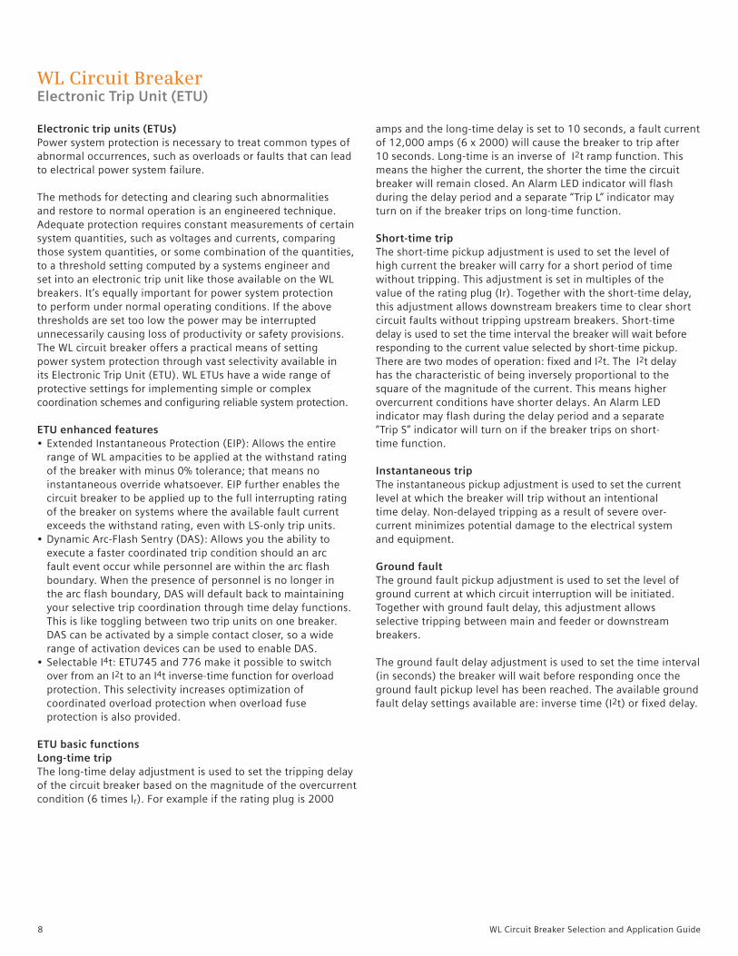
Electronic trip units (ETUs)Power system protection is necessary to treat common types of abnormal occurrences, such as overloads or faults that can lead to electrical power system failure.
The methods for detecting and clearing such abnormalities and restore to normal operation is an engineered technique. Adequate protection requires constant measurements of certain system quantities, such as voltages and currents, comparing those system quantities, or some combination of the quantities, to a threshold setting computed by a systems engineer and set into an electronic trip unit like those available on the WL breakers. It’s equally important for power system protection to perform under normal operating conditions. If the above thresholds are set too low the power may be interrupted unnecessarily causing loss of productivity or safety provisions.The WL circuit breaker offers a practical means of setting power system protection through vast selectivity available in its Electronic Trip Unit (ETU). WL ETUs have a wide range of protective settings for implementing simple or complex coordination schemes and configuring reliable system protection.
ETU enhanced features• Extended Instantaneous Protection (EIP): Allows the entire range of WL ampacities to be applied at the withstand rating of the breaker with minus 0% tolerance; that means no instantaneous override whatsoever. EIP further enables the circuit breaker to be applied up to the full interrupting rating of the breaker on systems where the available fault current exceeds the withstand rating, even with LS-only trip units.• Dynamic Arc-Flash Sentry (DAS): Allows you the ability to execute a faster coordinated trip condition should an arc fault event occur while personnel are within the arc flash boundary. When the presence of personnel is no longer in the arc flash boundary, DAS will default back to maintaining your selective trip coordination through time delay functions. This is like toggling between two trip units on one breaker. DAS can be activated by a simple contact closer, so a wide range of activation devices can be used to enable DAS.• Selectable I4t: ETU745 and 776 make it possible to switch over from an I2t to an I4t inverse-time function for overload protection. This selectivity increases optimization of coordinated overload protection when overload fuse protection is also provided.
ETU basic functionsLong-time tripThe long-time delay adjustment is used to set the tripping delay of the circuit breaker based on the magnitude of the overcurrent condition (6 times lr). For example if the rating plug is 2000
amps and the long-time delay is set to 10 seconds, a fault current of 12,000 amps (6 x 2000) will cause the breaker to trip after 10 seconds. Long-time is an inverse of I2t ramp function. This means the higher the current, the shorter the time the circuit breaker will remain closed. An Alarm LED indicator will flash during the delay period and a separate “Trip L” indicator may turn on if the breaker trips on long-time function.
Short-time tripThe short-time pickup adjustment is used to set the level of high current the breaker will carry for a short period of time without tripping. This adjustment is set in multiples of the value of the rating plug (Ir). Together with the short-time delay, this adjustment allows downstream breakers time to clear short circuit faults without tripping upstream breakers. Short-time delay is used to set the time interval the breaker will wait before responding to the current value selected by short-time pickup. There are two modes of operation: fixed and I2t. The I2t delay has the characteristic of being inversely proportional to the square of the magnitude of the current. This means higher overcurrent conditions have shorter delays. An Alarm LED indicator may flash during the delay period and a separate “Trip S” indicator will turn on if the breaker trips on short-time function.
Instantaneous tripThe instantaneous pickup adjustment is used to set the current level at which the breaker will trip without an intentional time delay. Non-delayed tripping as a result of severe over- current minimizes potential damage to the electrical system and equipment.
Ground faultThe ground fault pickup adjustment is used to set the level of ground current at which circuit interruption will be initiated. Together with ground fault delay, this adjustment allows selective tripping between main and feeder or downstream breakers.
The ground fault delay adjustment is used to set the time interval (in seconds) the breaker will wait before responding once the ground fault pickup level has been reached. The available ground fault delay settings available are: inverse time (I2t) or fixed delay.

9WL Circuit Breaker Selection and Application Guide
WL Circuit BreakerElectronic Trip Unit (ETU)
ETU models and features
Features and characteristics ETU745 ETU748 ETU776
Long-time overcurrent protection (L) X X X Short-time delayed overcurrent protection (S) X X X Instantaneous overcurrent protection (I) X X Neutral conductor protection (N) X X X Ground fault protection (G) O O O Selectable neutral protection X X X Defeatable short-time protection X X Defeatable instantaneous protection X X Selectable thermal memory X X X Zone selective interlocking X X X Selectable I2t or fixed short-time delay X X X Adjustable instantaneous pick-up X X X Selectable I2t or I4t long-time delay X X X Adjustable short-time delay and pick-up X X X Selectable and adjustable neutral protection X X X Dual protective setting capability X Dynamic arc-flash sentry (DAS) X Extended instantaneous protection (EIP) X X X Parameterization by rotary switches X X Parameterization by communication (absolute values) X Parameterization by menu/keypad (absolute values) X Remote parameterization of the alarm functions X Remote parameterization of the relay functions X Alphanumeric display O O X Graphical display X Power metering function O O O Communication via PROFIBUS-DP O O O Communication via the MODBUS O O O Communication via the Ethernet (BDA) O O O
(X) = standard feature, (O) = optional feature

10 WL Circuit Breaker Selection and Application Guide
ETU communicationThe ETU uses a Siemens proprietary communication network called CubicleBus. The CubicleBus network ensures all Siemens devices are able to transmit data reliably and efficiently. The ETU can not be connected directly any other network so the use of converters are necessary to allow communication between the ETU and the outside world. The WL has three types of converters to allow communication between the ETU and computer type equipment. The three converts are:• PROFIBUS (COM15)• ModBus (COM16)• HTML or TCP/IP (BDA)
The WL PROFIBUS converter is model ‘COM15.’ The COM15 device acts as an interface between the WL breaker and the information environment. A joint device master file (GSD) can be used for integrating WL circuit breakers in a PROFIBUS-DP network. The advantage of this joint communication profile is that the same software can be used for automation, monitoring and control systems.
The WL ModBus converter is model ‘COM16’. The COM16 device enables the WL breaker to be connected to any Modbus master network. Universal Modbus mapping can be used to allow custom monitoring and controls with a centralized monitoring system. The Modbus port is configured for RS485 connectivity and can easily be daisy-chained to several WL breakers to create a serial-network suitable for connecting to a LAN or WAN network.
The WL HTML or TCP/IP converter is called ‘BDA.’ The BDA is a microcomputer with an embedded Linux operating system running a web server application. The HTML pages and JAVA codes are stored internal to the BDA and can be accessed with an external PC web browser. All of the viewable web pages are stored in the BDA. The BDA communicates to the ETU through a front connected ribbon-cable. The PC accesses the BDA through an integral DB-9 serial port or an RJ45 Ethernet port.
All three converters require a 24VDC Class 2 power supply. See External Accessories for more information on available power supplies.
WL Circuit BreakerElectronic Trip Unit (ETU)

11WL Circuit Breaker Selection and Application Guide
WL Circuit BreakerElectronic Trip Unit (ETU)
Power metering functionIn addition to excellent protection capabilities, the WL ETU has unparalleled power metering functionality. True RMS current sensing for metering is obtained from the same current sensors
used for overload protection. ETU power metering can measure the following:
Potential transformers (PTs) are required to step down the supply voltage to a level that is suitable for local input connection to the breaker. PTs must be wired to the secondary connections of the breaker and configured for three-phase, three-wire or three-phase, four-wire supply system. The measured values can be sent to a central database for future power analysis or consumption reports.
Metering is not field installable – it must be configured in the initial breaker purchase.
Event logThe event log is very extensive. Information regarding the list of events can be found in the WL operation manual or communication guide. Some of the event log categories are:• Warnings• Trip Logs• Set-points• Maintenance Detail• CubicleBus Conditions• Waveform Displays
Measured value Value range Accuracy Currents Ia, Ib, Ic, In 30 ... 8000A ± 1% Ground-fault current Ig (measure with external Gnd transformer) 100 ... 1200A ± 5% Line-to-line voltages Vab, Vbc, Vca 80 ... 120% Vn ± 1% Line-to-neutral voltages Van, Vbn, Vcn 80 ... 120% Vn ± 1% Average value of phase-to-phase voltages V L-L AVG 80 ... 120% Vn ± 1% Apparent power kVA per phase 13 ... 8000kVA ± 2% Total apparent power KVA 13 ... 24000kVA ± 2% Active power kW per phase -8000 ... 8000kW ± 3% (power factor > 0.6) Total active power kW total -24000 ... 24000kVA ± 3% (power factor > 0.6) Reactive power kvar -6400 ... 6400kvar ± 4% (power factor > 0.6) Total reactive power kvar -20000 ... 20000kvar ± 4% (power factor > 0.6) Power factor per phase -0.6 ... 1 ... 0.6 ± 0.04 Power factor total -0.6 ... 1 ... 0.6 ± 0.04 Demand of currents Ia, Ib, Ic 30 ... 8000A ± 1% Average demand of 3-phase current 30 ... 8000A ± 1% Demand kWD per phase 13 ... 8000kW ± 3% (power factor > 0.6) kW demand 3-phase active power kWD total 13 ... 8000kW ± 3% (power factor > 0.6) kVA demand kVA total 13 ... 8000kVA ± 2% kVAR demand kVAR per phase 13 ... 8000kVA ± 2% kVAR demand total -24000 ... 24000kvar ± 4% (power factor > 0.6) kWhr imported 1 ... 10000MWh ± 2% kWhr exported 1 ... 10000MWh ± 2% kVARh imported 1 ... 10000Mvarh ± 4% kVARh exported 1 ... 10000Mvarh ± 4% Frequency 15 ... 440 Hz ± 0.1 Hz Total harmonic distortions for current and voltage 2 ... 100% ± 3% from the meas. range up to the 29th harmonic Phase unbalance for current and voltage 2 ... 150% ± 1%

12 WL Circuit Breaker Selection and Application Guide
Alarm parametersThe metering function includes the following alarm set-point functions:
Extended relayingProtective relays included with the metering function can monitor the following criteria and initiate a trip if the valuesare exceeded.
Protective relay function ANSI device number Setting range Possible delay
Current unbalance 46 5 ... 50% 1 ...15 s
Total harmonic distortion - current 81 THDC 0 ... 50% 5 ...15 s Voltage unbalance 47 5 ... 50% 1 ...15 s Undervoltage 27 100 ... 1100V 1 ...15 s Overvoltage 59 200 ... 1200V 1 ...15 s Total harmonic distortion - voltage 81 THDV 0 ... 50% 5 ...15 s Direction of phase rotation 47N Active power in normal direction 32 1 ... 10000kW 1 ...15 s Active power in reverse direction 32R 1 ... 10000kW 1 ...15 s Under frequency 81U 40 ... 70 Hz 1 ...15 s Over frequency 81O 40 ... 70 Hz 1 ...15 s
Alarm function Setting range Possible delay
Overcurrent 3 ... 10000A 0 ... 255 s
Overcurrent – ground fault 3 ... 10000A 0 ... 255 s Overcurrent – N-conductor 3 ... 10000A 0 ... 255 s Phase unbalance – current 5 ... 50% 0 ... 255 s Demand – current 3 ... 10000A 0 ... 255 s Total harmonic distortion – current 0 ... 50% 5 ... 255 s Undervoltage 100...1200V 0 ... 255 s Overvoltage 200...1200V 0 ... 255 s Phase unbalance – voltage 5 ... 50% 0 ... 255 s Total harmonic distortion – voltage 0 ... 50% 5 ... 255 s Crest factor 0.01 ... 25.5% 0 ... 255 s Form factor 0.01 ... 25.5% 0 ... 255 s Active power in normal direction 1 ... 10000kW 0 ... 255 s Active power in reverse direction 1 ... 10000kW 0 ... 255 s Leading power factor -0.999 ... 1 0 ... 255 s Lagging power factor -0.999 ... 1 0 ... 255 s Demand – active power 1 ... 10000kW 0 ... 255 s Apparent power 1 ... 10000kVA 0 ... 255 s Reactive power in normal direction 1 ... 10000kvar 0 ... 255 s Reactive power in reverse direction 1 ... 10000kvar 0 ... 255 s Demand – apparent power 1 ... 10000kVA 0 ... 255 s Demand – reactive power 1 ... 10000kvar 0 ... 255 s Underfrequency 40 ... 70 Hz 0 ... 255 s Overfrequency 40 ... 70 Hz 0 ... 255 s
WL Circuit BreakerElectronic Trip Unit (ETU)

13WL Circuit Breaker Selection and Application Guide
WL Circuit BreakerETU Function Overview
1 Extended Instantaneous Protection (EIP) allows the WL breaker to be applied at the withstand rating available of the breaker with minus 0% tolerance; that means no instantaneous override whatsoever. EIP further – not available enables the circuit breaker to be applied up to the full instantaneous rating of the breaker on systems optional where the available fault current exceeds the withstand rating.2 Ground Fault Module cannot be removed after installation.
Basic functions ETU745
Long-time overcurrent protection Function can be disabled – Setting range IR = In x ... 0.4, 0.45, 0.5, 0.55, 0.6, 0.65, 0.7, 0.8, 0.9, 1 Switch-selectable overload protection (I2t or I4t dependent function) Setting range of time delay class tR at I2t (seconds) 2, 3.5, 5.5, 8, 10, 14, 17, 21, 25, 30 Setting range of time delay tR at I4t (seconds) 1, 2, 3, 4, 5
Thermal memory (via slide switch) Phase loss sensitivity set tsd =20 ms (M) Neutral protection Function can be disabled (via slide switch) N-conductor setting range IN = In x ... 0.5 ... 1 Short-time overcurrent protection Function can be disabled (via rotary switch) Setting range Isd = In x ... 1.25, 1.5, 2, 2.5, 3, 4, 6, 8, 10, 12 Setting range of time delay tsd, fixed (constant time in seconds) 0.02 (M), 0.1, 0.2, 0.3, 0.4, OFF Setting range of time delay Isd at I2t (seconds) 0.1, 0.2, 0.3, 0.4
Zone Selective Interlocking (ZSI) function per CubicleBUS module Instantaneous overcurrent protection Function can be disabled Extended Instantaneous Protection Instantaneous is active when disabled Setting range Ii = In x ... 1.5, 2.2, 3, 4, 6, 8, 10, 12 0.8 x Icw = Max, Ground fault protection 2 O (field installable module) Trip and alarm function Detection of the ground fault current by residual summing method Detection of the ground fault current by direct sensing method Setting range of the Ig for trip A, B, C, D, E (100 ... 1200A) Setting range of the Ig for alarm A, B, C, D, E (100 ... 1200A) Setting range of the time delay tg
(fixed seconds) 0.1, 0.2, 0.3, 0.4, 0.5 Setting range time delay tg at I2t 0.4, 0., 0.3, 0.4, 0.5 ZSI ground function per CubicleBUS module
L
N
S
I
G

14 WL Circuit Breaker Selection and Application Guide
WL Circuit BreakerETU Function Overview
2 Extended Instantaneous Protection (EIP) allows the WL breaker to be applied at the withstand rating available of the breaker with minus 0% tolerance; that means no instantaneous override whatsoever. EIP further – not available enables the circuit breaker to be applied up to the full instantaneous rating of the breaker on systems o optional where the available fault current exceeds the withstand rating.3 Ground Fault Module cannot be removed after installation.4 Notes: M = indicates phase loss sensitivity is enabled. LT pick-up reduced 80% when phase unbalance > 50%. ST = 20 ms Key pad = Direct input at the trip unit.
L
N
S
I
G
1 Note: ETU776 settings via WLBDA, Modbus, or Profibus: 1A steps Via ETU Keypad: Below 1000A: 10A steps 1000A-1600A: 50A steps 1600A-10000A: 100A steps Above 10000A, 1000A steps
Basic functions ETU748 ETU776
Long-time overcurrent protection Function can be disabled – – Setting range IR = In x ... 0.4, 0.45, 0.5, 0.55, 40-100% of In (Adjustable in Amps1) 0.6, 0.65, 0.7, 0.8, 0.9, 1 Switch-selectable overload protection (I2t or I4t dependent function) Setting range of time delay class tR at I2t (seconds) 2, 3.5, 5.5, 8, 10, 2...30 (step; 0.1s) 14, 17, 21, 25, 30
Setting range of time delay tR at I4t (seconds) 1, 2, 3, 4, 5 1...5 (step; 0.1s) Thermal memory (via slide switch) (on/off via keypad or communications) Phase loss sensitivity at tsd =20 ms (M) (on/off via keypad or communications) Neutral protection Function can be disabled (via slide switch) (on/off via keypad or communications) N-conductor setting range IN = In x ... 0.5 ... 1 OFF 0.5 ... 2 OFF Short-time delayed overcurrent protection Function can be switched ON/OFF (via rotary switch) (on/off via keypad or communications)
Setting range Isd = In x ... 1.25, 1.5, 2, 2.5, 1.25... 0.9 x Icw = max 3, 4, 6, 8, 10, 12 (step: 10A) Setting range of time delay tsd, fixed (seconds) M, 0.1, 0.2, 0.3, 0.4 M, 0.08... 04, OFF (step: 0.001s)
Switch-selectable short-time delay short-circuit protection (I2t dependent function) (via rotary switch) (via keypad or communications) Setting range of time delay Isd at I2t (seconds) 0.1, 0.2, 0.3, 0.4 0.1... 0.4 (step 0.001s)
Zone Selective Interlocking (ZSI) function per CubicleBUS module per CubicleBUS module
Instantaneous overcurrent protection 2 Function can be disabled, Extended Instantaneous Protection is enabled when OFF – (via keypad or communications)
Setting range Ii = In x ... Ii = Icw = EIP 1.5 ... 0.8 x Ics = MAX OFF = Icw = EIP
Ground fault protection 3 O (field installable module) O (field installable module) Trip and alarm function Detection of the ground fault current by residual summing method Detection of the ground fault current by direct sensing method
Setting range of the Ig for trip A, B, C, D, E A... E (step: 1A) Setting range of the Ig for alarm A, B, C, D, E A... E (step: 1A) Setting range of the time delay tg
(seconds) 0.1, 0.2, 0.3, 0.4, 0.5 0.1...0.5 (step: 0.001s) Switch-selectable ground fault protection (I2t / fixed) Setting range time delay tg at I2t 0.1, 0.2, 0.3, 0.4, 0.5 0.1...0.5 (step: 0.001s) ZSI ground function per CubicleBUS module per CubicleBUS module

15WL Circuit Breaker Selection and Application Guide
Ground fault moduleThe ground fault module (GFM) is used to detect current flowing through the grounding conductors which may present a hazardous condition. The module can be field installed but can’t be removed once installed. Residual sensing by phase vector summation or direct sensing can be selected on the module or via the setup of the ETU776. Ground fault modules may be ordered as alarm only or as alarm and trip. Alarm will provide a visual and communication notification. Alarm and trip model will trip the breaker in addition to alarm notification.
Key lock-outTo lock the WL breaker in the “Open” position, an optional keylock can be installed in the breaker. The key cylinder and lock-out assembly are mounted in the breaker and accessible through a knockout in the breaker front cover. The key is removable only when the breaker is locked open. If a custom, coordinated key/cylinder is required, order the lock provision-only. The lock cylinder and matched key must then be ordered separately from the respective lock manufacturer.
The compatible Kirk cylinder lock part number is C-900-301.The compatible Superior cylinder lock part number is C-900.
Operation counterFor monitoring the number of breaker operations (open and close) a numerical operations counter is available. This counter is only suitable for breakers equipped with the spring-charging motor option. The counter mounts to the motor assembly and will register manual and electrical breaker operations. Counter is non-resettable up to 100,000 operations. Counter ships with available pre-service operations for field setting to zero.
1 See page 106 for field install part numbers.
WL Circuit BreakerFactory Installed Options1
Auxiliary contacts Auxiliary contacts can be used to provide interlocking control or remote indication of the breakers main contact position (open or closed breaker). The Normally Open (NO) contacts are open when the breakers main contacts are open. The Normally Closed (NC) contacts are closed when the breakers main contacts are open. The contacts are wired individually to the secondary disconnects for user connectivity. See breaker wiring diagram for supply terminal locations.
Breaker status sensor (BSS)BSS is an integrated circuit device that measures the internal breaker temperature, monitors breaker main contact position (open or closed), bell alarm status, shunt trip status, breaker ready-to-close and closing spring charged status. All status conditions and information is transmitted through the CubicleBus network as real-time data. A COM16 (Modbus), COM15 (PROFIBUS) or a BDA (breaker display adapter) accessory can be used to export the BSS CubicleBus data to external computer or monitoring equipment. See breaker wiring diagram for supply terminal locations. Included with COM15 and COM16.
Characteristics table
Available Contact Configurations 2NO and 2NC or 4NO and 4NC
AC Operation Voltage 240VAC 50/60Hz Continuous Current 10A Making Current 30A Breaking Current 3ADC Operation Voltage 24, 125, 250VDC Continuous Current 5A Making Current 1.1A @ 24 or 125VDC, .55A @250VDC Breaking Current 1.1A @ 24 or 125VDC, .55A @250VDC
Characteristics tableOperating Voltage 24VDCPeak Inrush Current 110mAMax. Continuous Current 40mAAmbient Operation Temperature -25 to 70ºC
Breaker mounted options

16 WL Circuit Breaker Selection and Application Guide
1 See page 106 for field install part numbers.
Bell alarm contact and reset coilThe bell alarm contacts are mechanically activated by the trip unit solenoid. If a breaker trip condition occurs, the bell alarm form-C contacts will change state closing or opening a user circuit wired to the secondary terminal block. The contacts can be locally reset to their original position by manually resetting the breaker trip button or through the use of a reset coil that resets the contacts remotely. See breaker wiring diagram for supply terminal locations. Non-automatic (manual) reset trip units can not be used with the reset coil option.
Characteristics table
WL Circuit BreakerFactory Installed Options 1
Close coilTo remotely close the WL breaker, a close coil must be used with a momentary electrical source. Only one close coil can be used per breaker. Charging springs must be charged and breaker open prior to activating the close coil. See breaker wiring diagram for supply terminal location.
Breaker push button lock-outsA finger or hand tool shroud option can be added to thebreaker front cover to isolate the open and close buttons from unintentional use. Shrouds may be used in combination or like configuration.
To isolate the open and close buttons from unintentional use, transparent padlock covers can be installed in lieu of the shroud option. Two padlocks may be used with a latch diameter of 3/8 inch maximum (padlocks by others).
Racking handle key lockA draw-out breaker can be key locked (optional) or padlocked (standard not shown) in three racking positions; connect, test or disconnect. Key lock cylinders are available in Kirk or Superior types and uniquely keyed.
Characteristics table
120VAC Range 104 - 127VACClose Coil 240VAC Range 208 - 254AC Operation Power Consumption 120W for 50ms (5% duty cycle) Breaker closing time 50ms from point of signal 24VDC 14 - 28VDC 48VDC 28 - 56VDCClose Coil 125VDC 70 - 140VDCDC Operation 250VDC 140 - 280VDC Power Consumption 120W for 50ms (5% duty cycle) Breaker closing time 50ms from point of signal
Available contact configurations Coil ratings
Remote Voltage 240VAC 50/60HzReset Coil Continuous Current 5AAC Operation Making Current 8A Breaking Current 5ARemote Voltage 24, 48,125 or 250VDC Reset Coil Continuous Current 5ADC Operation Making Current .4A @ 24, 48,125VDC, .2A @250VDC Breaking Current .4A @ 24, 48,125VDC, .2A @250VDC
17WL Circuit Breaker Selection and Application Guide
1 See page 85 for field install part numbers.
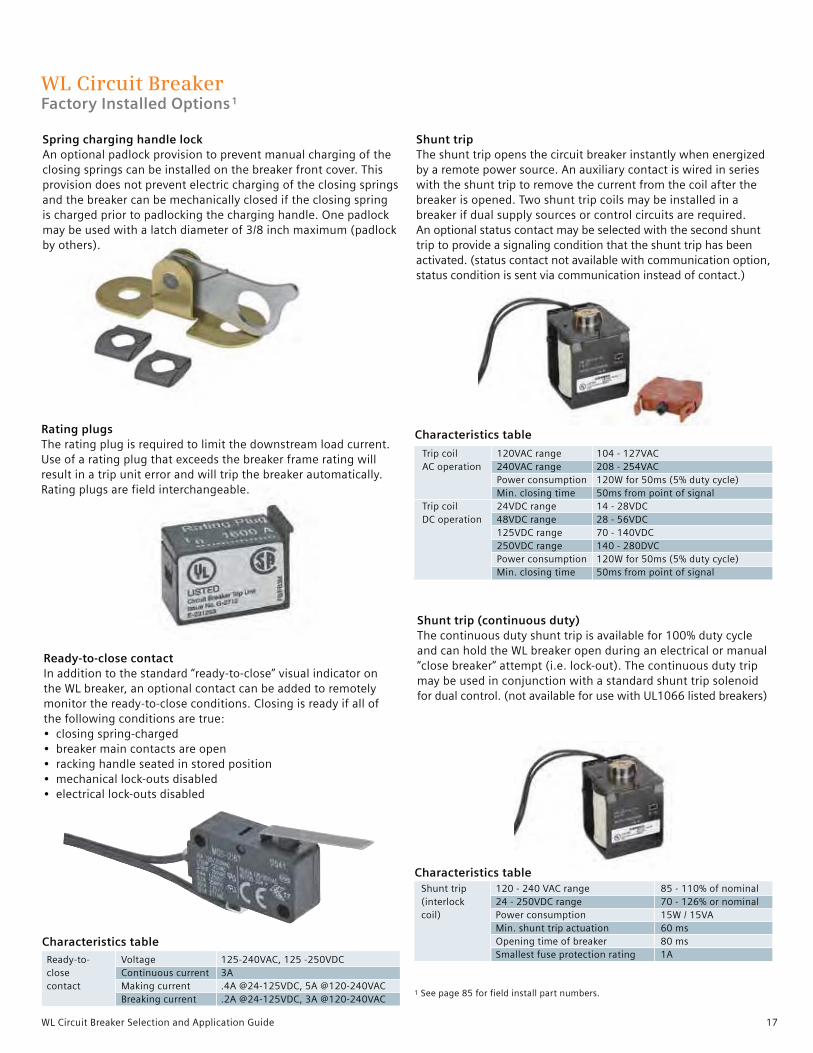
Spring charging handle lockAn optional padlock provision to prevent manual charging of the closing springs can be installed on the breaker front cover. This provision does not prevent electric charging of the closing springs and the breaker can be mechanically closed if the closing spring is charged prior to padlocking the charging handle. One padlock may be used with a latch diameter of 3/8 inch maximum (padlock by others).
Ready-to-close contactIn addition to the standard “ready-to-close” visual indicator on the WL breaker, an optional contact can be added to remotely monitor the ready-to-close conditions. Closing is ready if all of the following conditions are true:• closing spring-charged• breaker main contacts are open• racking handle seated in stored position• mechanical lock-outs disabled• electrical lock-outs disabled
WL Circuit BreakerFactory Installed Options1
Characteristics table
Trip coil 120VAC range 104 - 127VACAC operation 240VAC range 208 - 254VAC Power consumption 120W for 50ms (5% duty cycle) Min. closing time 50ms from point of signalTrip coil 24VDC range 14 - 28VDCDC operation 48VDC range 28 - 56VDC 125VDC range 70 - 140VDC 250VDC range 140 - 280DVC Power consumption 120W for 50ms (5% duty cycle) Min. closing time 50ms from point of signal
Shunt trip (continuous duty)The continuous duty shunt trip is available for 100% duty cycle and can hold the WL breaker open during an electrical or manual “close breaker” attempt (i.e. lock-out). The continuous duty trip may be used in conjunction with a standard shunt trip solenoid for dual control. (not available for use with UL1066 listed breakers)
Shunt trip 120 - 240 VAC range 85 - 110% of nominal(interlock 24 - 250VDC range 70 - 126% or nominalcoil) Power consumption 15W / 15VA Min. shunt trip actuation 60 ms Opening time of breaker 80 ms Smallest fuse protection rating 1A
Characteristics table
Ready-to- Voltage 125-240VAC, 125 -250VDCclose Continuous current 3Acontact Making current .4A @24-125VDC, 5A @120-240VAC Breaking current .2A @24-125VDC, 3A @120-240VAC
Shunt tripThe shunt trip opens the circuit breaker instantly when energized by a remote power source. An auxiliary contact is wired in series with the shunt trip to remove the current from the coil after the breaker is opened. Two shunt trip coils may be installed in a breaker if dual supply sources or control circuits are required. An optional status contact may be selected with the second shunt trip to provide a signaling condition that the shunt trip has been activated. (status contact not available with communication option, status condition is sent via communication instead of contact.)
Rating plugsThe rating plug is required to limit the downstream load current. Use of a rating plug that exceeds the breaker frame rating will result in a trip unit error and will trip the breaker automatically. Rating plugs are field interchangeable.
Characteristics table
18 WL Circuit Breaker Selection and Application Guide
1 See page 106 for field install part numbers.
Characteristics table
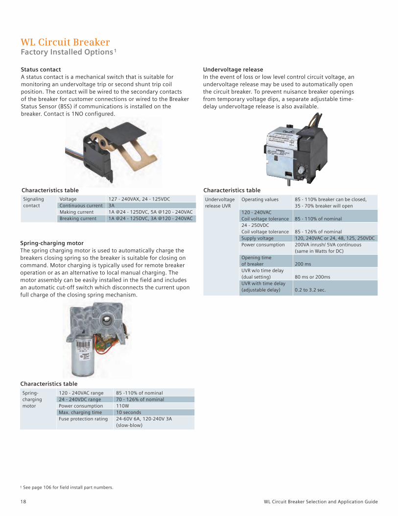
Spring-charging motorThe spring charging motor is used to automatically charge the breakers closing spring so the breaker is suitable for closing on command. Motor charging is typically used for remote breaker operation or as an alternative to local manual charging. The motor assembly can be easily installed in the field and includes an automatic cut-off switch which disconnects the current upon full charge of the closing spring mechanism.
Characteristics table
Spring- 120 - 240VAC range 85 -110% of nominalcharging 24 - 240VDC range 70 - 126% of nominalmotor Power consumption 110W Max. charging time 10 seconds Fuse protection rating 24-60V 6A, 120-240V 3A (slow-blow)
Signaling Voltage 127 - 240VAX, 24 - 125VDCcontact Continuous current 3A Making current 1A @24 - 125DVC, 5A @120 - 240VAC Breaking current 1A @24 - 125DVC, 3A @120 - 240VAC
Characteristics table
Undervoltage Operating values 85 - 110% breaker can be closed, release UVR 35 - 70% breaker will open 120 - 240VAC Coil voltage tolerance 85 - 110% of nominal 24 - 250VDC Coil voltage tolerance 85 - 126% of nominal Supply voltage 120, 240VAC or 24, 48, 125, 250VDC Power consumption 200VA inrush/ 5VA continuous (same in Watts for DC) Opening time of breaker 200 ms UVR w/o time delay (dual setting) 80 ms or 200ms UVR with time delay (adjustable delay) 0.2 to 3.2 sec.
Undervoltage releaseIn the event of loss or low level control circuit voltage, an undervoltage release may be used to automatically open the circuit breaker. To prevent nuisance breaker openings from temporary voltage dips, a separate adjustable time-delay undervoltage release is also available.
Status contactA status contact is a mechanical switch that is suitable for monitoring an undervoltage trip or second shunt trip coil position. The contact will be wired to the secondary contacts of the breaker for customer connections or wired to the Breaker Status Sensor (BSS) if communications is installed on the breaker. Contact is 1NO configured.
WL Circuit BreakerFactory Installed Options1

19WL Circuit Breaker Selection and Application Guide
Characteristics table
Wire connection type Number of wires and sizes
Secondary Screw compression 1 x 14AWG or 2 x 16AWGdisconnects Tension spring compression 2 x 14AWG Ring lug terminal 2 x 14AWG or 2 x 16AWG
PROFIBUS or MODBUS communicationPROFIBUS or MODBUS communication requires a COM15 or COM16 converter to transmit WL breaker data to external PCs or PLC monitoring systems. External communication connection to either module is through a DB-9F connector.
Characteristics tableOperating voltage 24VDCPeak inrush current 280mAMax. continuous current 125mAAmbient temperature -25 to 70ºC
WL Circuit BreakerFactory Installed Options1
The following items are available for WL cradles. Items are described to highlight the functional characteristics of these factory installed cradle options.
Secondary disconnectsSecondary disconnects are used to interconnect external breaker control and signaling circuitry to the WL breakers factory wired circuitry. Three types of external connection terminals are available. 1. Screw connection, 2. Tension spring connection and, 3. Ring lug connection. (tension spring connection terminals are standard for fixed mounted breakers)
1 See page 106 for field install part numbers.
Isolation shuttersWhen removing a draw-out breaker from its connected position the primary contacts become exposed and more accessible to personnel in the breaker compartment. Isolation shutters reduce that accessibility to the primary terminals by automatically closing the access ports to the primary terminals wheneverthe breaker is disconnected or withdrawn. After removal of the breaker from its compartment, the shutters may be padlocked to inhibit manual shutter opening while breaker is not in the compartment.
Dual key breaker lockingFor draw-out breakers, a cradle-mounted breaker lockout device can be installed with either one or two independent key cylinders. The key is removable only when the breaker is locked open. Cradle-mounted key locks are commonly utilized for interlocking in open transition schemes, where paralleling certain sources is not desirable. Siemens offers the choice of unique, uncoordinated, Kirk and Superior key lock types. If a custom, coordinated key/ cylinder is required, order the lock provision-only. The lock cylinder and matched key must then be ordered separately from the respective lock manufacturer.
The compatible Kirk cylinder lock part number is C-900-301.The compatible Superior cylinder lock part number is C-900.

20 WL Circuit Breaker Selection and Application Guide
1 See page 106 for field install part numbers.
Arc chute coverThe arc chute cover is available for isolating enclosure material or parts located above the circuit breaker where heat and exhaust gases may exit from the breakers arc chutes. (arc chute covers are limited to select draw-out breaker types)
TOC (Truck Operated Contacts)For draw-out breaker applications a TOC device is available to provide remote indication of the circuit breakers primary and secondary contact connections (racking positions). When the breaker is racked into a connected, test or disconnected position, it activates TOC switches for external user circuits.
WL Circuit BreakerCradle Factory Installed Options1
MOC (Mechanism Operated Contacts)Mechanism Operated Contacts (MOC) are a cradle mounted accessory which indicate the state of the breaker’s internal contacts (open or closed). MOCs are typically utilized when additional auxiliary contacts are necessary – above and beyond the number configurable in the circuit breaker – although they may also be used in lieu of the internal auxiliary switches. Each MOC assembly includes 4 ‘a’ and 4 ‘b’ contacts. Two different MOC assemblies are available. One version operates when the circuit breaker is in both the “TEST” and “CONNECTED” positions, and the other version operates only when the circuit breaker is in the “CONNECTED” position.
Note per ANSI C37.100:‘a’ contact: a contact that is open when the main device is in the standard reference position and that is closed when the device is in the opposite position.
‘b’ contact: a contact that is closed when the main device is in the standard reference position and that is open when the device is in the opposite position.
Characteristics table
MOC contact configurations 4NO and 4NC
AC operation Voltage 240VAC 50/60Hz Continuous current 10A Making current 30A Breaking current 3ADC operation Voltage 24, 125, 250VDC Making current 1.1A @ 125VDC, .55A @250VDC Breaking current 1.1A @ 125VDC, .55A @250VDC
TOC Switch Breaker disconnected = primary Breaker in test = primary Breaker connected = primary and secondary contacts contacts disconnected and and secondary contacts are disconnected secondary contacts connected are connected
Option 1 1 form C contacts 1 form C contacts 1 form C contacts
Option 2 1 form C contacts 2 form C contacts 3 form C contacts Option 3 0 form C contacts 0 form C contacts 6 form C contacts
AC voltage 120, 240VAC AC continuous current 10A TOC Contact Ratings AC making/breaking current 6A@120V, 3A@240VAC DC voltage 24, 48, 125, 250VDC DC continuous current 6A, 1A, 1A DC making/breaking current 6A, 0.22A, 0.11A

21WL Circuit Breaker Selection and Application Guide
Breaker Data Adapter PLUSThe BDAP can be used to read or modify the breaker ETU and Cubiclebus parameters using a laptop, pocket PC or remote desktop PC. Circuit breakers can be parameterized individually using one BDA with similar or different parameters. No software is required as the embedded software interface is through a PC browser. Connectivity to a PC or network can be serial (RS232) or Ethernet (TCP/IP) address. If the breaker ETU is energized with 24VDC control power the BDA can be powered through the interconnecting ribbon cable. Order part number WLBDAP
WL Circuit BreakerAccessories
Handheld test deviceTo test the WL breakers ETU trip functions we offer a hand-held tester that checks:• Sensor continuity• Long-time function• Short-time function• Instantaneous function• Neutral and ground fault function
During a test, the device will electrically trip the circuit breaker performing a full function test of the ETU and the trip actuator. Cables for 120VAC power supply and ETU connection is included with the tester. Order part number WLTS
Communication power suppliesFor WL devices that require a 24VDC input we offer the Siemens SITOP power supply. The SITOP power supply is a class 2 rated devices suitable for supporting loads of 2.5 or 3.8 amps. DIN rail mounting provision and compression wire connections included.For loads of 2.5A maximum order part number WLSITOP25 or WLSITOP1 for 3.8A maximum loads.
Mechanical breaker interlocksMechanical interlock options are available for fixed or draw-out breakers. Interlocking is managed through cable connections between two or three breakers less than 6 meters apart. Lock kit includes 2.0 meter interlocking cable and mechanism for mounting to a single breaker.
For fixed breaker frame size 1 order part number WLNTLKF1For fixed breaker frame size 2 or 3, order part number WLNTLKF23
For draw-out breaker frame size 1, 2, or 3,order part number WLNTLK
For alternate cable lengths, order part number
3.0 meter WLNTLWRE3 4.5 meter WLNTLWRE4
6.0 meter WLNTLWRE5

22 WL Circuit Breaker Selection and Application Guide
WL Circuit BreakerAccessories
Metering current transformer 3-phase window (cradle mounting only)For draw-out breaker applications, a three phase metering CT is available. Termination screws are integral to the mold for point-to-point wiring without the use of terminal blocks or wire couplers. Metering ratios range from 800:5 to 5000:5. CTs include mounting hardware.
For frame size 3 order part numbers:
3200:5 Rating WLG32005MCT3 4000:5 Rating WLG40005MCT3 5000:5 Rating WLG50005MCT3
Metering current transformer – single phaseA single piece housing that is compact and designed to fit around phase or neutral bussing. Termination screws are integral to the mold for point-to-point wiring without the use of terminal blocks or wire couplers. Metering ratios range from 800:5 to 5000:5.
For frame size 1 and 2 order part numbers:
800:5 Rating WLG8005MCT2 1200:5 Rating WLG12005MCT2 1600:5 Rating WLG16005MCT2 2000:5 Rating WLG20005MCT2 2500:5 Rating WLG25005MCT2 3200:5 Rating WLG32005MCT2
For frame size 1, 2 or 3, order part numbers:
800:5 Rating WLG800NMCT23 1200:5 Rating WLG1200NMCT23 1600:5 Rating WLG1600NMCT23 2000:5 Rating WLG2000NMCT23 2500:5 Rating WLG2500NMCT23 3000:5 Rating WLG3000NMCT23 3200:5 Rating WLG3200NMCT23 4000:5 Rating WLG4000NMCT23 5000:5 Rating WLG5000NMCT23
4W Modified Differential Ground Fault (MDGF)For MDGF draw-out breaker applications, a three phase iron-core CT is available. The MDGF CTs are physically the same as the above metering CTs but the current ratio is 1200:1.
For frame size 2, breakers order part number: 1200:1 rating WLGMDGFCT2 Phase CT
For frame size 3, breakers order part number: 1200:1 rating WLGMDGFCT3 Phase CT
For frame size 2 and 3, neutral CT order part number: 1200:1 rating WLGNMDGCT23 Neutral CT
A typical application for modified differential ground fault is ‘Main-Tie-Main’ where all breakers require 3 Phase CTs and a neutral CT.

23WL Circuit Breaker Selection and Application Guide
WL Circuit BreakerAccessories
Neutral current sensor – 4-wire residual ground faultFor 4-wire residual ground fault protection we offer neutral current sensors with or without bus bar coupling. The sensors are comparable to the sensors used within the breaker and connected to the ETU. This sensor must also be wired to the ETU through designated secondary disconnects on the breaker.
Without copper bus adapters: 3” max bus bar width order part number WLNCT2 3 - 5” bus bar width order part number WLNCT3With copper bus adapters: 3” max bus bar width order part number WLNCT2CB 3 - 5” bus bar width order part number WLNCT3CB
Breaker door coverA transparent hinged door cover is available to provide IP55 protection. Provision for padlocking included. Fits frame size 2 and 3 breakers. Order part number WLPGC
Door sealing frameFor openings around the door cutout of the breaker, this rubber door trim is available. For frame size 2 and 3 breakers only.Order part number WLDSF
Breaker lifting The breaker lifting yolk is designed to transport the WL breaker when using a hoist or other lifting equipment. The device is expandable to conform to all three WL frame sizes and easily attaches to specified lift points on the breaker. Order part number WLLFT
Remote Breaker Racking DeviceProvides the ability to safely rack WL breakers into the Connect, Test and Disconnect positions from 30 feet away from the breaker, allowing the operator to be outside the arc flash boundary which provides additional personnel protection. WLRBRD
Door Bracket Kit, Remote Breaker Racking Device In order to mount the remote breaker racking device on existing gear, this retrofit door bracket kit and the WLRBRDTEMPL must be ordered. WLRBRDKIT
Remote Breaker Racking Device Door Bracket Install Template In order to mount the remote breaker racking device on existing gear, this mounting template and the WLRBRDKIT must be ordered. WLRBRDTEMPL
Breaker HoistThis device acts as a hoist for the WL breaker, allowing it to be carried using a forklift or similar device. WLHOIST

24 WL Circuit Breaker Selection and Application Guide
Analog output moduleThe analog output module can be used to output the most important measured values sent via the CubicleBUS to analog indicators (e.g. analog meters) in the switchgear cubicle door. Each analog output module has four channels for this purpose. The signals are available at two physical interfaces: a 4 ... 20mA and a 0 ... 10V interface.
Analog output module: order part number WLANLGCUB
Pre-assembled CubicleBUS communication cables (RJ45-M connections)
1 meter length: order part number WLCBUSCABLE1 2 meter length: order part number WLCBUSCABLE2 4 meter length: order part number WLCBUSCABLE4 9 meter length: order part number WLCBUSCABLE9
WL Circuit BreakerAccessories
Digital input moduleThe digital input module enables up to six additional binary signals (24V DC) to be connected. Signals, such as breaker status, arc-flash current reduction, over-temperature conditions or control circuit status switchgear, can be transmitted directly to the power monitoring network.
A total of 6 inputs are available in the “BUS Input” Switch position. Six inputs are also available if the rotary switch is in the “Parameter Switch” position, although the first input causes the active parameter set to change. If the connected ETU does not have two parameter set capability (e.g. ETU745 or ETU748), this input can also be used without any restrictions.
Digital Input Module: Order part number WLDGNCUB
CubicleBUS modulesExternal CubicleBUS modules enable the WL Circuit Breaker a way to interface with external switchgear controls or building management systems. They can be used, for example, to activate analog displays or devices, transmit circuit breaker status and cause of trip, or read external device control signals. One module is suitable for zone-selective interlocking main and branch breakers.
Three different CubicleBUS modules can output data from the CubicleBUS system (two digital output modules and one analog output module). A digital input module can transmit data from the switchgear or system to a PROFIBUS/MODBUS master device like a power meters or logic controllers.
Digital Output Module with Rotary Switch – The digital output module can be used to output six events. These events can be warnings or trips and can be used for external annunciation or control. The load shedding and load restoring signals can enable a load to be switched ON or OFF automatically. Voltages of up 250V AC/DC are possible. The relay contacts are isolated.
Relay Digital Output Module: Order part number WLRLYCUB
ZSI moduleTo use the ZSI function with the WL Circuit Breaker, the external CubicleBUS ZSI module must be implemented. The zone selective interlocking (ZSI) module provides the complete range of selectivity with the short delay time of tZSI = 50 ms, irrespective of the number of levels and the location of the short-circuit in a distribution system. Its benefits become even more apparent, the higher the number of levels in large systems and the longer the resulting delay times. By shortening the time, the ZSI module significantly reduces stress and damage in the event of a short-circuit in the switchgear.
Zone Selective Interlocking Module: Order part number WLZSIMD

25WL Circuit Breaker Selection and Application Guide
Frame size 1, 1200A max, 65 kAIC at 480V, order part number WLS2P12CONUL
Frame size 2, 1600 to 2000A max, 65kA 65 kAIC at 480V, order part number
WLS2P20CONUL
WL Circuit BreakerAccessories
Mechanical lug connector kits are available for connecting 800 to 2000A WL front connector bus kits (sold separately) to power cables.
Fixed mounted breaker rear bus connector kits are available for adapting WL breaker primary mounting stabs to a standard NEMA bussing and bolt-hole pattern. Adapters also rotate the primary breaker connections by 90° for vertical bus arrangement. Bolted connections are accessible from the rear of the breaker. Kit includes the required bus and hardware for mounting one 3-pole set of adapters to a breaker.
Fixed-mounted breaker front bus connectorsFront connector bus kits are available for adapting WL breaker primary mounting stabs to a standard NEMA bussing and bolt-hole pattern. NEMA bolt connection is accessible from the front of the breaker for ease of installation or removal of breaker inside an enclosure. Kit includes the required bus and hardware for mounting one 3-pole set of adapters to a breaker.
Frame size 1, 1200A frame, 85 kAIC at 480V, order part number WLH1F12CONUL Frame size 2, 1600A frame, 100kAIC at 480V, order part number WLL2F16CONUL Frame size 2, 2000A frame, 100kAIC at 480V, order part number WLL2F20CONUL Frame size 2, 2500A frame, 100kAIC at 480V, order part number WLL2F25CONUL Frame size 2, 3000A frame, 100kAIC at 480V, order part number WLL2F30CONUL Frame size 3, 4000 to 5000A frame, 100kAIC at 480V, order part number WLL3F50CONUL
Frame size 1, 1200A frame, 85 kAIC at 480V, order part number WLH1R12CONUL Frame size 2, 1600A frame, 100 kAIC at 480V, order part number WLL2R16CONUL Frame size 2, 2000A frame, 100 kAIC at 480V, order part number WLL2R20CONUL Frame size 2, 3000A frame, 100 kAIC at 480V, order part number WLL2R30CONUL Frame size 2, 800A to 3000A frame, 150 kAIC at 480V rated breaker only order part number WLC2R30CONUL Frame size 3, 4000A to 5000A frame, 100 kAIC at 480V order part number WLC3R50CONUL

26 WL Circuit Breaker Selection and Application Guide
WL Power Circuit BreakerWL Catalog Numbering Overview
1 2 3 4 5 6 7 8 9 10 11 12 13 14 15Digit Number
Interrupting Class
Frame Size
Breaker Type
Number of Poles
Frame Ampere Rating
Rating Plug
Electronic Trip Unit (ETU)
Bell Alarm, Breaker Ready-to-Close, Auxiliary Contacts
Shunt Trip
Undervoltage Release (with or without time delay) or 2nd Shunt Trip
Charging Motor, Motor Switch, Operations Counter
Close Coil, Power Metering and Communications
Breaker Locks
Miscellaneous Options
27WL Circuit Breaker Selection and Application Guide
Note: Frame Size 1 H-Class only for switches
WL Insulated Case Circuit BreakerRatings for UL489 Listed Breakers
WL frame ratings – frame size 1 800A 1200A 1600A 2000A
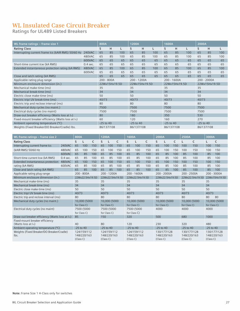
Rating Class S H L S H L S H L S H L Interrupting current frame Ics (kAIR RMS) 50/60 Hz 240VAC 65 85 100 65 85 100 65 85 100 65 85 100 480VAC 65 85 100 65 85 100 65 85 100 65 85 100 600VAC 65 65 65 65 65 65 65 65 65 65 65 65 Short-time current Icw (kA RMS) 0.4 sec. 65 65 65 65 65 65 65 65 65 65 65 65 Extended instantaneous protection rating (kA RMS) 480VAC 65 85 100 65 85 100 65 85 100 65 85 100 600VAC 65 65 65 65 65 65 65 65 65 65 65 65 Close and latch rating (kA RMS) 65 65 65 65 65 65 65 65 65 65 65 65 Applicable rating plug range 200 - 800A 200 - 1200A 200 - 1600A 200 - 2000A Minimum enclosure dimension (in.) 22Wx15Hx19.5D 22Wx15Hx19.5D 22Wx15Hx19.5D 22Wx15Hx19.5D Mechanical make-time (ms) 35 35 35 35 Mechanical break-time (ms) 34 34 34 34 Electric close make-time (ms) 50 50 50 50 Electric trip/ UV break-time (ms) 40/73 40/73 40/73 40/73 Electric trip and reclose interval (ms) 80 80 80 80 Mechanical duty cycles (no maint.) 7500 7500 7500 7500 Electrical duty cycles (no maint) 7500 7500 7500 7500 Draw-out breaker efficiency (Watts loss at In) 80 180 350 530 Fixed-mount breaker efficiency (Watts loss at In) 60 120 160 270 Ambient operating temperature (ºC) -25 to 40 -25 to 40 -25 to 40 -25 to 40 Weights (Fixed Breaker/DO Breaker/Cradle) lbs. 86/137/108 86/137/108 86/137/108 86/137/108
WL frame ratings – frame size 2 800A 1200A 1600A 2000A 2500A 3000A
Rating Class S L C S L C S L C S L C L C L C Interrupting current frame Ics 240VAC 65 100 150 65 100 150 65 100 150 65 100 150 100 150 100 150
(kAIR RMS) 50/60 Hz 480VAC 65 100 150 65 100 150 65 100 150 65 100 150 100 150 100 150 600VAC 65 85 100 65 85 100 65 85 100 65 85 100 85 100 85 100 Short-time current Icw (kA RMS) 0.4 sec. 65 85 100 65 85 100 65 85 100 65 85 100 85 100 85 100 Extended instantaneous protection 480VAC 65 100 150 65 100 150 65 100 150 65 100 150 100 150 100 150 rating (kA RMS) 600VAC 65 85 100 65 85 100 65 85 100 65 85 100 85 100 85 100 Close and latch rating (kA RMS) 65 85 100 65 85 100 65 85 100 65 85 100 85 100 85 100 Applicable rating plug range 200 - 800A 200 - 1200A 200 - 1600A 200 - 2000A 200 - 2500A 200 - 3000A Minimum enclosure dimension (in.) 22Wx22.5Hx19.5D 22Wx22.5Hx19.5D 22Wx22.5Hx19.5D 22Wx22.5Hx19.5D 22Wx22.5Hx19.5D 22Wx15Hx19.5D Mechanical make-time (ms) 35 35 35 35 35 35 Mechanical break-time (ms) 34 34 34 34 34 34 Electric close make-time (ms) 50 50 50 50 50 50 Electric trip/ UV break-time (ms) 40/73 40/73 40/73 40/73 40/73 40/73 Electric trip and reclose interval (ms) 80 80 80 80 80 80 80 Mechanical duty cycles (no maint.) 10,000 (5000 10,000 (5000 10,000 (5000 10,000 (5000 10,000 (5000 10,000 (5000 for Class C) for Class C) for Class C) for Class C) for Class C) for Class C) Electrical duty cycles (no maint) 7500 (5000 7500 (5000 7500 (5000 4000 4000 4000 for Class C) for Class C) for Class C) Draw-out breaker efficiency (Watts loss at In) 85 150 320 500 680 1000 Fixed-mount breaker efficiency (Watts loss at In) 40 80 120 230 320 480 Ambient operating temperature (ºC) -25 to 40 -25 to 40 -25 to 40 -25 to 40 -25 to 40 -25 to 40 Weights (Fixed Breaker/DO Breaker/Cradle) 124/159/112 124/159/112 124/159/112 130/177/128 130/177/128 130/177/128 lbs. 148/220/163 148/220/163 148/220/163 148/220/163 148/220/163 148/220/163 (Class C) (Class C) (Class C) (Class C) (Class C) (Class C)
28 WL Circuit Breaker Selection and Application Guide
WL Insulated Case Circuit BreakerRatings for UL489 Listed Breakers
WL frame ratings – Frame size 3 4000A 5000A
Rating Class L C L C
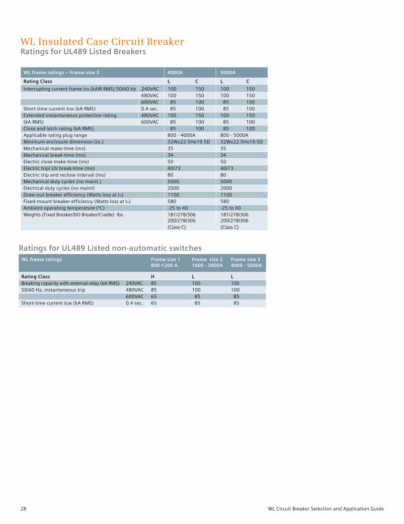
Interrupting current frame Ics (kAIR RMS) 50/60 Hz 240VAC 100 150 100 150 480VAC 100 150 100 150 600VAC 85 100 85 100 Short-time current Icw (kA RMS) 0.4 sec. 85 100 85 100 Extended instantaneous protection rating 480VAC 100 150 100 150 (kA RMS) 600VAC 85 100 85 100 Close and latch rating (kA RMS) 85 100 85 100 Applicable rating plug range 800 - 4000A 800 - 5000A Minimum enclosure dimension (in.) 32Wx22.5Hx19.5D 32Wx22.5Hx19.5D Mechanical make-time (ms) 35 35 Mechanical break-time (ms) 34 34 Electric close make-time (ms) 50 50 Electric trip/ UV break-time (ms) 40/73 40/73 Electric trip and reclose interval (ms) 80 80 Mechanical duty cycles (no maint.) 5000 5000 Electrical duty cycles (no maint) 2000 2000 Draw-out breaker efficiency (Watts loss at In) 1100 1100 Fixed-mount breaker efficiency (Watts loss at In) 580 580 Ambient operating temperature (ºC) -25 to 40 -25 to 40 Weights (Fixed Breaker/DO Breaker/Cradle) lbs. 181/278/306 181/278/306 200/278/306 200/278/306 (Class C) (Class C)
Ratings for UL489 Listed non-automatic switches WL frame ratings Frame size 1 Frame size 2 Frame size 3 800-1200 A 1600 - 3000A 4000 - 5000A Rating Class H L L Breaking capacity with external relay (kA RMS) 240VAC 85 100 100 50/60 Hz, instantaneous trip 480VAC 85 100 100 600VAC 65 85 85 Short-time current Icw (kA RMS) 0.4 sec. 65 85 85

29WL Circuit Breaker Selection and Application Guide
WL Insulated Case Circuit BreakerUL 489 Listed Catalog Number
Breaker catalog number 1 1 2 3 4 5 6 7 8 9 10 11 12 13 14 15 Class Interrupt rating (kA) Frame Frame size Breaker type 240VAC Max ampere Fixed Fixed 480VAC 600VAC rating (A) 1 2 3 mount Drawout
S 65 65 800 X X S 1 F 3 0 8 S 65 65 800 X X S 2 F 3 0 8 S 65 65 800 X X S 1 D 3 0 8 S 65 65 800 X X S 2 D 3 0 8 S 65 65 1200 X X S 1 F 3 1 2 S 65 65 1200 X X S 2 F 3 1 2 S 65 65 1200 X X S 1 D 3 1 2 S 65 65 1200 X X S 2 D 3 1 2 S 65 65 1600 X X S 1 F 3 1 6 S 65 65 1600 X X S 2 F 3 1 6 S 65 65 1600 X X S 1 D 3 1 6 S 65 65 1600 X X S 2 D 3 1 6 S 65 65 2000 X X S 1 F 3 2 0 S 65 65 2000 X X S 2 F 3 2 0 S 65 65 2000 X X S 1 D 3 2 0 S 65 65 2000 X X S 2 D 3 2 0 L 100 65 800 X X L 1 F 3 0 8 L 100 85 800 X X L 2 F 3 0 8 L 100 65 800 X X L 1 D 3 0 8 L 100 85 800 X X L 2 D 3 0 8 L 100 65 1200 X X L 1 F 3 1 2 L 100 85 1200 X X L 2 F 3 1 2 L 100 65 1200 X X L 1 D 3 1 2 L 100 85 1200 X X L 2 D 3 1 2 L 100 65 1600 X X L 1 F 3 1 6 L 100 85 1600 X X L 2 F 3 1 6 L 100 65 1600 X X L 1 D 3 1 6 L 100 85 1600 X X L 2 D 3 1 6 L 100 65 2000 X X L 1 F 3 2 0 L 100 85 2000 X X L 2 F 3 2 0 L 100 65 2000 X X L 1 D 3 2 0 L 100 85 2000 X X L 2 D 3 2 0 L 100 85 2500 X X L 2 F 3 2 5 L 100 85 2500 X X L 2 D 3 2 5 L 100 85 3000 X X L 2 F 3 3 0 L 100 85 3000 X X L 2 D 3 3 0 L 100 85 4000 X X L 3 F 3 4 0 L 100 85 4000 X X L 3 D 3 4 0 L 100 85 5000 X X L 3 F 3 5 0 L 100 85 5000 X X L 3 D 3 5 0 C 150 100 800 X X C 2 F 3 0 8 C 150 100 800 X X C 2 D 3 0 8 C 150 100 1200 X X C 2 F 3 1 2 C 150 100 1200 X X C 2 D 3 1 2 C 150 100 1600 X X C 2 F 3 1 6 C 150 100 1600 X X C 2 D 3 1 6 C 150 100 2000 X X C 2 F 3 2 0 C 150 100 2000 X X C 2 D 3 2 0 C 150 100 2500 X X C 2 F 3 2 5 C 150 100 2500 X X C 2 D 3 2 5 C 150 100 3000 X X C 2 F 3 3 0 C 150 100 3000 X X C 2 D 3 3 0 C 150 100 4 000 X X C 3 F 3 4 0 C 150 100 4000 X X C 3 D 3 4 0 C 150 100 5000 X X C 3 F 3 5 0 C 150 100 5000 X X C 3 D 3 5 0
Interrupting rating, frame size, breaker type and frame ratingNote: Cradle must be ordered separately for drawout breaker types (see page 36) 1 2 3 4 5 6 7 8 9 10 11 12 13 14 15

30 WL Circuit Breaker Selection and Application Guide
WL Insulated Case Circuit BreakerUL 489 Listed Catalog Number
Rating Plug
Electronic trip unit (ETU)1)
Protective Trip unit function LCD display Ground fault models L S I Alpha num. Alarm Trip ETU745 X (X) (X) C ETU745 X (X) (X) X D ETU745 X (X) (X) X E ETU745 X (X) (X) X X F ETU745 X (X) (X) X X G ETU745 X (X) (X) X X X H ETU748 X X J ETU748 X X X K ETU748 X X X L ETU748 X X X X N ETU748 X X X X P ETU748 X X X X X Q ETU776 X (X) (X) V ETU776 X (X) (X) X W ETU776 X (X) (X) X X Y (X) Indicates function can be disabled by user
1 Neutral protection “N” is available as standard.
Breaker catalog number
A B C D E F G H J K L M N P Q R T U V W Z 1
1 2 3 4 5 6 7 8 9 10 11 12 13 14 15
1 Maximum For use with
continuous frame size current rating 1 2 3
200 X X 225 X X 250 X X 300 X X 315 X X 350 X X 400 X X 450 X X 500 X X 600 X X 630 X X 700 X X 800 X X X 1000 X X X 1200 X X X 1250 X X X 1600 X X X 2000 X X X 2500 X X 3000 X X 4000 X 5000 X

31WL Circuit Breaker Selection and Application Guide
Bell alarm, breaker ready-to-close, auxiliary contacts
Bell alarm Remote reset Breaker Breaker open/close coil voltage Form C ready-to-close auxiliary switches AC DC contacts 1b contact 2a + 2b 4a + 4b None X X A X B X C X D X X E X X F X X G X X H X X I X X X J X X X K 24 X L 48 X M 120 125 X N 240 250 X O 24 X X P 48 X X Q 120 125 X X R 240 250 X X S 24 X X T 48 X X U 120 125 X X V 240 250 X X W 24 X X Y 48 X X Z 120 125 X X 1 240 250 X X 2 24 X X X 3 48 X X X 4 120 125 X X X 5 240 250 X X X 6 24 X X X 7 48 X X X 8 120 125 X X X 9 240 250 X X X 0
WL Insulated Case Circuit BreakerUL 489 Listed Catalog Number
Breaker catalog number
Operation voltage Status Continuous duty coil AC DC contact (electrical interlock) None X 24 A 48 B 120 125 C 240 250 D 24 X E 48 X F 120 125 X G 240 250 X H 24 X J 48 X K 120 125 X L 240 250 X M 24 X X N 48 X X P 120 125 X X R 240 250 X X S
Shunt trip
1 2 3 4 5 6 7 8 9 10 11 12 13 14 15

32 WL Circuit Breaker Selection and Application Guide
Undervoltage Release (with or without time delay) or 2nd Shunt Trip
Operation voltage UVR UVR UVR status1 2nd AC DC without delay with delay contact (1NO) shunt trip None X 24 X A 48 X B 120 125 X C 240 250 X D 48 X E 120 125 X F 240 250 X G 24 X H 48 X J 120 125 X K 240 250 X L 24 X X M 48 X X N 120 125 X X P 240 250 X X Q 48 X X R 120 250 X X S 240 250 X X T
WL Insulated Case Circuit BreakerUL 489 Listed Catalog Number
Breaker catalog number
Charging motor operation voltage Motor cut-off Operations
AC DC switch counter None X 24 A 48 B 120 125 C 240 250 D 24 X E 48 X F 120 125 X G 240 250 X H 24 X J 48 X K 120 125 X L 240 250 X M 24 X X N 48 X X P 120 125 X X Q 240 250 X X R
1 Status contact is only available when Communications is not installed on breaker. Signal is sent via communications in lieu of status contact.
Charging motor, motor switch, operations counter
1 2 3 4 5 6 7 8 9 10 11 12 13 14 15

33WL Circuit Breaker Selection and Application Guide
WL Insulated Case Circuit BreakerUL 489 Listed Catalog Number
1 2 3 4 5 6 7 8 9 10 11 12 13 14 15 Close coil, power metering and communications
Breaker locks Key lock breaker Key lock breaker Padlock provisions for Padlock provisions OPEN position (lock OPEN position (lock OPEN and CLOSE for charging type – KIRK) 1 type – SUPERIOR) 1 push buttons 2 handle 2
None X X A X C X E X F X X G X X J X X S X X U X X V X X X W X X X Z
1 Custom key locks are not available and must be supplied by others. Order key lock provision if custom if keyed alike locks are required.2 Locks provided by others.
Miscellaneous options
Key lock breaker Manual trip reset ETU OPEN position (provision only)2 (Automatic trip reset is standard)
None N X B X C X X D
Breaker catalog number 1 1
Close coil Power metering operation voltage capable MODBUS 2 PROFIBUS 2 AC DC None X 24 A 48 B 120 125 C 240 250 D X G X H 24 X N 24 X P 48 X S 48 X T 120 125 X W 120 125 X Y 240 250 X 2 240 250 X 3 24 X X Q 48 X X U 120 125 X X Z 240 250 X X 4 24 X X R 48 X X V 120 125 X X 1 240 250 X X 5 X X L X X M X F 24 X 6 48 X 7 120 125 X 8 240 250 X 9

34 WL Circuit Breaker Selection and Application Guide
WL Insulated Case SwitchUL 489 Listed Non-automatic Catalog Number
Breaking capacity, frame size, switch type and frame rating 1 2 3 4 5 6 7 8 9 10 11 12 13 14 15 Switch catalog number 1 Class Breaking capacity (kA) Frame Frame size Switch type 240VAC Max ampere Fixed 480VAC 600VAC rating (A) 2 3 mounted drawout
L 100 85 1600 X X L 2 Y 3 1 6 S S L 100 85 1600 X X L 2 Z 3 1 6 S S L 100 85 2000 X X L 2 Y 3 2 0 S S L 100 85 2000 X X L 2 Z 3 2 0 S S L 100 85 2500 X X L 2 Y 3 2 5 S S L 100 85 2500 X X L 2 Z 3 2 5 S S L 100 85 3000 X X L 2 Y 3 3 0 S S L 100 85 3000 X X L 2 Z 3 3 0 S S L 100 85 4000 X X L 3 Y 3 4 0 S S L 100 85 4000 X X L 3 Z 3 4 0 S S L 100 85 5000 X X L 3 Y 3 5 0 S S L 100 85 5000 X X L 3 Z 3 5 0 S S
Ready-to-close and auxiliary contacts Ready-to-close Breaker open/close auxiliary switches 1b contact 2a + 2b 4a + 4b None X X B X C X D X X H X X I

35WL Circuit Breaker Selection and Application Guide
1 2 3 4 5 6 7 8 9 10 11 12 13 14 15
WL Insulated Case SwitchUL 489 Listed Non-automatic Catalog Number
Switch catalog number
Operation voltage Status Shunt Continuous duty rated AC DC contact1 trip (electrical interlock) None X 24 X A 48 X B 120 125 X C 240 250 X D 24 X X E 48 X X F 120 125 X X G 240 250 X X H 24 X J 48 X K 120 125 X L 240 250 X M 24 X X N 48 X X P 120 125 X X R 240 250 X X S
Shunt trip
Undervoltage release (with or without time delay) or 2nd shunt trip
Operation voltage UVR UVR UVR status 1 2nd shunt AC DC without delay with delay contact (1NO) trip None X 24 X A 48 X B 120 125 X C 240 250 X D 48 X E 120 125 X F 240 250 X G 24 X H 48 X J 120 125 X K 240 250 X L 24 X X M 48 X X N 120 125 X X P 240 250 X X Q 48 X X R 120 250 X X S 240 250 X X T
1 Status contact is only available when communication is not installed. Signal is sent via communications in lieu of status contact.

36 WL Circuit Breaker Selection and Application Guide
1 Requires 24VDC power supply. Power metering not available on non-automatic switches and BSS is included.
WL Insulated Case SwitchUL 489 Listed Non-automatic Catalog Number
Switch catalog number Charging motor, motor switch and operation counter 1 2 3 4 5 6 7 8 9 10 11 12 13 14 15
Charging motor operation voltage Motor cut-off Operations
AC DC switch counter
None X 24 A 48 B 120 125 C 240 250 D 24 X E 48 X F 120 125 X G 240 250 X H 24 X J 48 X K 120 125 X L 240 250 X M 24 X X N 48 X X P 120 125 X X Q 240 250 X X R
Close coil, communications Close coil operation voltage
AC DC Modbus 1 PROFIBUS 1
None X X G 24 A 24 X N 48 B 48 X S 120 125 C 120 125 X W 240 250 D 240 250 X 2 X H 24 X P 48 X T 120 125 X Y 240 250 X 3

37WL Circuit Breaker Selection and Application Guide
WL Insulated Case Circuit SwitchUL 489 Listed Non-automatic Catalog Number
Switch locks 1 2 3 4 5 6 7 8 9 10 11 12 13 14 15
1 Custom key locks are not available and must be supplied by others. Order Key Lock Provisions if custom keys or keyed alike locks are required. 2 Padlock provided by others.
Switch catalog number
Key lock breaker Key lock breaker Padlock provisions for Padlock provisions OPEN position (lock OPEN position (lock OPEN and CLOSE for charging type – KIRK) 1 type – SUPERIOR) 1 push buttons 2 handle
None X X A X C X E X F X X G X X J X X S X X U X X V X X X W X X X Z
Miscellaneous options
Key lock breaker OPEN position (provision only) 2
None N X B

38 WL Circuit Breaker Selection and Application Guide
WL Insulated Case Circuit BreakerUL 489 Listed Accessories
External breaker accessories
Description Catalog number
Front mount connectors for fixed breakers FS1, 85kAIC at 480V max. 800A, 1200A WLHF12CONUL FS2, 100kAIC at 480V max. 1600A WLL2F16CONUL FS2, 100kAIC at 480V max. 2000A WLL2F20CONUL FS2, 100kAIC at 480V max. 3000A WLL2F30CONUL FS3, 100kAIC at 480V max. 4000A, 5000A WLL3F50CONUL Mechanical lug FS1, FS2, 65kAIC at 480V max 800A, 1200A WLS2P12CONUL FS2, 65kAIC at 480V max 1600A, 2000A WLS2P20CONUL Rear vertical connectors FS1, 85kAIC at 480V max 800A, 1200A WLH1R12CONUL FS2, 100kAIC at 480V max 1600A WLL2R16CONUL FS2, 100kAIC at 480V max 2000A WLL2R20CONUL FS2, 1100kAIC at 480V max 2500A, 3000A WLL2R30CONUL FS2, 150kAIC at 480V max 1600A, 2000A, 2500A, 3000A WLC2R30CONUL FS3, 150kAIC at 480V max 4000A, 5000A WLC3R50CONUL Single phase CTs for metering, 5A secondary Rating: 800:5 WLG800NMCT23 Rating: 1200:5 WLG1200NMCT23 Rating: 1600:5 WLG1600NMCT23 Rating: 2000:5 WLG2000NMCT23 Rating: 2500:5 WLG2500NMCT23 Rating: 3000:5 WLG3000NMCT23 Rating: 4000:5 WLG4000NMCT23 Rating: 5000:5 WLG5000NMCT23 Modified differential ground fault (MDGF) CTs Modified differential GF (FS2 1200:1) Phase CT WLGMDGFCT2 Modified differential GF (FS3 1200:1) Phase CT WLGMDGFCT3 Modified differential GF (FS2 and FS3 1200:1) Neutral CT WLGNMDGFCT23 4-wire residual ground fault sensor Without copper bus adapters (pass-thru mount) - for 3” max bus bar WLNCT2 Without copper bus adapters (pass-thru mount) - for 3 - 5” max bus bar WLNCT3 With copper bus adapters for bus bar connection - for 3” max bus bar WLNCT2CB With copper bus adapters for bus bar connection - for 3 - 5” max bus bar WLCNMDGCT23 Mechanical interlocks Fixed mounted breaker (FS1) WLNTLKF1 Fixed mounted breaker (FS2 and FS3) WLNTLKF23 Miscellaneous external accessories Crimp lugs for 10# AWG secondary wiring (package of 70) WL10RL Auxiliary contact on drawout breaker (knife block) WLCNMD 24V DC trip unit and communications power supply, 2.5A SITOP power, Class 2 WLSITOP25 24V DC trip unit and communications power supply 3.8A SITOP power, Class 2 WLSITOP1 Optional metric inserts and bolts for breaker mains (4 each) M8x25 for FS1 and FS2 WLMETRC Optional metric inserts and bolts for breaker mains (4 each) M10x25 for FS2 and FS3 WLMETRC3 Secondary disconnect coding kit for UL 489 fixed mounted breaker WLCODEKITUL Pull apart terminal block with 1 meter leads for UL 489 fix mounted breakers WLTERMBLKUL
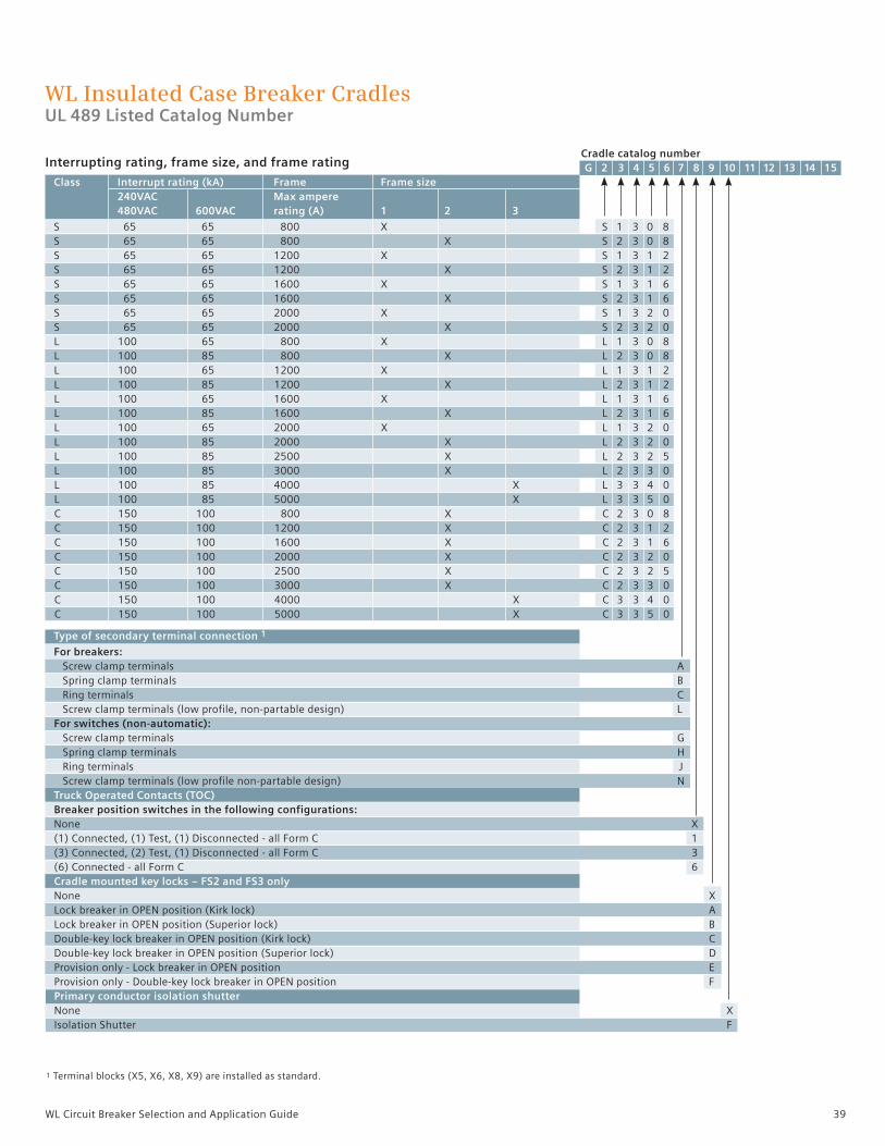
39WL Circuit Breaker Selection and Application Guide
WL Insulated Case Breaker CradlesUL 489 Listed Catalog Number
Cradle catalog number 1 G G 2 3 4 5 6 7 8 9 10 11 12 13 14 15 Class Interrupt rating (kA) Frame Frame size 240VAC Max ampere 480VAC 600VAC rating (A) 1 2 3
S 65 65 800 X S 1 3 0 8 S 65 65 800 X S 2 3 0 8 S 65 65 1200 X S 1 3 1 2 S 65 65 1200 X S 2 3 1 2 S 65 65 1600 X S 1 3 1 6 S 65 65 1600 X S 2 3 1 6 S 65 65 2000 X S 1 3 2 0 S 65 65 2000 X S 2 3 2 0 L 100 65 800 X L 1 3 0 8 L 100 85 800 X L 2 3 0 8 L 100 65 1200 X L 1 3 1 2 L 100 85 1200 X L 2 3 1 2 L 100 65 1600 X L 1 3 1 6 L 100 85 1600 X L 2 3 1 6 L 100 65 2000 X L 1 3 2 0 L 100 85 2000 X L 2 3 2 0 L 100 85 2500 X L 2 3 2 5 L 100 85 3000 X L 2 3 3 0 L 100 85 4000 X L 3 3 4 0 L 100 85 5000 X L 3 3 5 0 C 150 100 800 X C 2 3 0 8 C 150 100 1200 X C 2 3 1 2 C 150 100 1600 X C 2 3 1 6 C 150 100 2000 X C 2 3 2 0 C 150 100 2500 X C 2 3 2 5 C 150 100 3000 X C 2 3 3 0 C 150 100 4000 X C 3 3 4 0 C 150 100 5000 X C 3 3 5 0
Type of secondary terminal connection 1
For breakers: Screw clamp terminals A Spring clamp terminals B Ring terminals C Screw clamp terminals (low profile, non-partable design) L For switches (non-automatic): Screw clamp terminals G Spring clamp terminals H Ring terminals J Screw clamp terminals (low profile non-partable design) N Truck Operated Contacts (TOC) Breaker position switches in the following configurations: None X (1) Connected, (1) Test, (1) Disconnected - all Form C 1 (3) Connected, (2) Test, (1) Disconnected - all Form C 3 (6) Connected - all Form C 6 Cradle mounted key locks – FS2 and FS3 only None X Lock breaker in OPEN position (Kirk lock) A Lock breaker in OPEN position (Superior lock) B Double-key lock breaker in OPEN position (Kirk lock) C Double-key lock breaker in OPEN position (Superior lock) D Provision only - Lock breaker in OPEN position E Provision only - Double-key lock breaker in OPEN position F Primary conductor isolation shutter None X Isolation Shutter F
Interrupting rating, frame size, and frame rating
1 Terminal blocks (X5, X6, X8, X9) are installed as standard.

40 WL Circuit Breaker Selection and Application Guide
WL Insulated Case Breaker CradleUL 489 Listed Catalog Number
Cradle catalog number G 2 3 4 5 6 7 8 9 10 11 12 13 14 15 Arc chute covers
None X Arc chute cover s (FS1 only) C Arc chute covers (FS2 only) D Arc chute covers (FS3 only – except Class C) B Door locks and mechanical interlocks
1. Mechanical interlock with 2.0 meter Bowden cable 2. Locks cubicle door, when breaker is in connect position (FS2 and FS3) 3. Locks cubicle door, when breaker is in connect position (FS1 only) 4. Locks against racking breaker if the cubicle door is open (FS2 and FS3) 1 2 3 4 None X X M X A X B X C X X D X X X E X X F X X G X X H Mechanism Operated Contacts (MOC) Breaker open/close auxiliary switches (4a & 4b) in the following positions: None X Test and Connect position (FS1 and FS2 only) M Connect position (FS1 and FS2 only) N Test and Connect position (FS3 only) P Connect position (FS3 only) Q Connector and heater options Standard rear connectors X Standard rear connectors and a cradle heater (FS2 and FS3) H Rotatable rear connector (FSI and FS2 2000A and below, S Class) J Rotatable rear connectors and a cradle heater (FS2 2000A and below, S Class) K Future use Placeholder (required) N

41WL Circuit Breaker Selection and Application Guide
WL Insulated Case Breaker CradlesUL 489 Listed Accessories
Cradle accessories Catalog number 3-phase metering CTs, cradle mounted (3 windows per CT) FS1 and FS2 Rating – 800:5 WLG8005MCT2 Rating – 1200:5 WLG12005MCT2 Rating – 1600:5 WLG16005MCT2 FS2 Rating – 2500:5 WLG25005MCT2 Rating – 3000:5 WLG30005MCT2 FS3 Rating – 4000:5 WLG40005MCT3 Rating – 5000:5 WLG50005MCT3

42 WL Circuit Breaker Selection and Application Guide
1 Maintenance means: replacing main contacts and arc chutes (see operating instructions). M-Class main contacts can be replaced by Siemens personnel only.
WL Power Circuit BreakerRatings for UL 1066 Listed (ANSI C37) Breakers
WL frame ratings – Frame size 2 800A 1600A
Rating Class N S H L F N S H L F Interrupting current frame Ics (kAIC RMS) 50/60 Hz 254VAC 50 65 85 100 200 50 65 85 100 200 508VAC 50 65 85 100 200 50 65 85 100 200 600VAC — — — — 200 — — — — 200 635VAC 50 65 65 85 — 50 65 65 85 — Short-time current Icw (kA RMS) 1 sec. 50 65 65 85 — 50 65 65 85 — Close and latch rating (kA RMS) 50 65 65 85 — 50 65 65 85 — Applicable rating plug range 200 - 800A 200 - 1600A Mechanical make-time (ms) 35 35 Mechanical break-time (ms) 34 34 Electric close make-time (ms) 50 50 Electric trip/ UV break-time (ms) 40/73 40/73 Electric trip and reclose interval (ms) 80 80 Mechanical duty cycles (with maint.) 1 15,000 15,000 Electrical duty cycles (with maint.) 1 15,000 15,000 Draw-out breaker efficiency (Watts loss at rated In) 85 320 Draw-out fused breaker efficiency (Watts loss at rated In) Consult factory Consult factory Ambient operating temperature (ºC) -25 to 40 -25 to 40 Weights (Fused Breaker/Breaker/Cradle) lbs. 227/159/112 227/159/112
WL frame ratings – Frame size 2 2000A 3200A
Rating Class S H L F S H L
Interrupting current frame Ics 254VAC 65 85 100 200 65 85 100 (kAIC RMS) 50/60 Hz 508VAC 65 85 100 200 65 85 100 600VAC — — — 200 — — — 635VAC 65 65 85 — 65 65 85 Short-time current Icw (kA RMS) 1 sec. 65 65 85 — 65 65 85 Close and latch rating (kA RMS) 65 65 85 — 65 65 85 Applicable rating plug range 200 - 2000A 200 - 3200A Mechanical make-time (ms) 35 35 Mechanical break-time (ms) 34 34 Electric close make-time (ms) 50 50 Electric trip/ UV break-time (ms) 40/73 40/73 Electric trip and reclose interval (ms) 80 80 Mechanical duty cycles (with maint.) 1 15,000 15,000 Electrical duty cycles (with maint.) 1 15,000 15,000 Draw-out breaker efficiency (Watts loss at rated In) 700 1650 Draw-out fused breaker efficiency (Watts loss at rated In) Consult factory Consult factory Ambient operating temperature (ºC) -25 to 40 -25 to 40 Weights (Fused Breaker/Breaker/Cradle) lbs. 227/209/152 227/209/152

43WL Circuit Breaker Selection and Application Guide
1 Maintenance means: replacing main contacts and arc chutes (see operating instructions). M-Class main contacts can be replaced by Siemens personnel only. Do not apply switch or breaker rated at 635VAC to a system with fault current > 85kA RMS.2 Short-time withstand current (Icw) at 635 VAC is kAIC RMS.3 Max. 600 VAC.4 3200A frame rating is only available in L-Class in Frame Size 2. 3200A frame rating is not available in L-Class in Frame Size 3.
WL Power Circuit BreakerRatings for UL 1066 Listed (ANSI C37) Breakers
1
Ratings for UL 1066 Listed Non-automatic Switches WL frame ratings Frame size 2 Frame size 3
800A - 3200A 4 3200 - 5000A 4
Rating Class F L F L Breaking capacity with external relay (kA RMS) 254VAC 200 100 200 100 50/60 Hz, instantaneous trip 508VAC 200 100 200 100 635VAC 200 85 200 85 Short-time current Icw (kA RMS) 1 sec. N/A 65 N/A 100
WL frame ratings – Frame size 3 3200A 4000A 5000A
Rating Class M F H L M F H L M F Interrupting current frame Ics 254VAC 150 200 85 100 150 200 85 100 150 200 (kAIC RMS) 50/60 Hz 508VAC 150 200 85 100 150 200 85 100 150 200 600VAC — 200 — — — 200 — — — 200 635VAC 85 — 85 85 85 — 85 85 85 — Short-time current Icw (kA RMS) 1 sec. 100 — 85 100 100 — 85 100 100 — Close and latch rating (kA RMS) 100 — 85 100 100 — 85 100 100 — Applicable rating plug range 800 - 3200A 800 - 4000A 800 - 5000 A Mechanical make-time (ms) 35 35 35 Mechanical break-time (ms) 34 34 24 Electric close make-time (ms) 50 50 50 Electric trip/ UV break-time (ms) 40/73 40/73 40/73 Electric trip and reclose interval (ms) 80 80 80 Mechanical duty cycles (with maint.) 1 10,000 10,000 10,000 Electrical duty cycles (with maint.) 1 10,000 10,000 10,000 Draw-out breaker efficiency (Watts loss at rated In) 700 1100 1650 Draw-out fused breaker efficiency (Watts loss at rated In) Consult factory Consult factory Consult Factory Ambient operating temperature (ºC) -25 to 40 -25 to 40 -25 to 40 Weights (Fused Carriage/Breaker/Cradle) lbs. 225/260/306 225/260/306 225/260/306
2
33
2
2
2
2
2
2
2
2
2
2

44 WL Circuit Breaker Selection and Application Guide
WL Power Circuit BreakerUL 1066 Listed Catalog Number
Interrupting rating, frame size, breaker type and frame ratingNote: Cradle must be ordered separately (see page 49) 1 2 3 4 5 6 7 8 9 10 11 12 13 14 15 Breaker catalog number Class Interrupt rating (kA) Frame Frame size Fuse (A) 254VAC Max ampere 508VAC 635VAC rating (A) 2 3 N 50 50 800 X N 2 A 3 0 8 N 50 50 1600 X N 2 A 3 1 6 S 65 65 800 X S 2 A 3 0 8 S 65 65 1600 X S 2 A 3 1 6 S 65 65 2000 X S 2 A 3 2 0 S 65 65 3200 X S 2 A 3 3 2 H 85 65 800 X H 2 A 3 0 8 H 85 65 1600 X H 2 A 3 1 6 H 85 65 2000 X H 2 A 3 2 0 H 85 65 3200 X H 2 A 3 3 2 H 85 85 4000 X H 3 A 3 4 0 H 85 85 5000 X H 3 A 3 5 0 L 100 85 800 X L 2 A 3 0 8 L 100 85 1600 X L 2 A 3 1 6 L 100 85 2000 X L 2 A 3 2 0 L 100 85 3200 X L 2 A 3 3 2 L 100 85 4000 X L 3 A 3 4 0 L 100 85 5000 X L 3 A 3 5 0 M 150 85 3200 X M 3 A 3 3 2 M 150 85 4000 X M 3 A 3 4 0 M 150 85 5000 X M 3 A 3 5 0 F 200 200 800 X 400 F 2 A 3 0 A F 200 200 800 X 600 F 2 A 3 0 B F 200 200 800 X 800 F 2 A 3 0 C F 200 200 800 X 900 F 2 A 3 0 D F 200 200 800 X 1000 F 2 A 3 0 E F 200 200 800 X 1200 F 2 A 3 0 F F 200 200 800 X 1600 F 2 A 3 0 G F 200 200 800 X 2000 F 2 A 3 0 H F 200 200 800 X 2500 F 2 A 3 0 J F 200 200 800 X 3000 F 2 A 3 0 K F 200 200 1600 X 400 F 2 A 3 1 A F 200 200 1600 X 600 F 2 A 3 1 B F 200 200 1600 X 800 F 2 A 3 1 C F 200 200 1600 X 900 F 2 A 3 1 D F 200 200 1600 X 1000 F 2 A 3 1 E F 200 200 1600 X 1200 F 2 A 3 1 F F 200 200 1600 X 1600 F 2 A 3 1 G F 200 200 1600 X 2000 F 2 A 3 1 H F 200 200 1600 X 2500 F 2 A 3 1 J F 200 200 1600 X 3000 F 2 A 3 1 K F 200 200 2000 X 400 F 2 A 3 2 A F 200 200 2000 X 600 F 2 A 3 2 B F 200 200 2000 X 800 F 2 A 3 2 C F 200 200 2000 X 900 F 2 A 3 2 D F 200 200 2000 X 1000 F 2 A 3 2 E F 200 200 2000 X 1200 F 2 A 3 2 F F 200 200 2000 X 1600 F 2 A 3 2 G F 200 200 2000 X 2000 F 2 A 3 2 H F 200 200 2000 X 2500 F 2 A 3 2 J F 200 200 2000 X 3000 F 2 A 3 2 K F 200 200 3200 X 6000 F 3 A 3 3 2 F 200 200 4000 X 6000 F 3 A 3 4 0 F 200 200 5000 X 6000 F 3 A 3 5 0
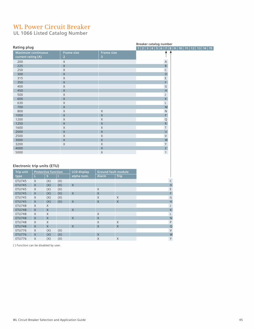
45WL Circuit Breaker Selection and Application Guide
WL Power Circuit BreakerUL 1066 Listed Catalog Number
Breaker catalog number
Maximum continuous Frame size Frame size current rating (A) 2 3
200 X A 225 X B 250 X C 300 X D 315 X E 350 X F 400 X G 450 X H 500 X J 600 X K 630 X L 700 X M 800 X X N 1000 X X P 1200 X X Q 1250 X X R 1600 X X T 2000 X X U 2500 X X V 3000 X X W 3200 X X Y 4000 X Z 5000 X 1
Rating plug 1 2 3 4 5 6 7 8 9 10 11 12 13 14 15
Electronic trip units (ETU)
Trip unit Protective function LCD display Ground fault module type L S I alpha num. Alarm Trip
ETU745 X (X) (X) C ETU745 X (X) (X) X D ETU745 X (X) (X) X E ETU745 X (X) (X) X X F ETU745 X (X) (X) X X G ETU745 X (X) (X) X X X H ETU748 X X J ETU748 X X X K ETU748 X X X L ETU748 X X X X N ETU748 X X X X P ETU748 X X X X X Q ETU776 X (X) (X) V ETU776 X (X) (X) X W ETU776 X (X) (X) X X Y ( ) Function can be disabled by user.

46 WL Circuit Breaker Selection and Application Guide
Control voltage Status AC DC contact None X 24 A 48 B 120 125 C 240 250 D 24 X E 48 X F 120 125 X G 240 250 X H
Shunt trip
WL Power Circuit BreakerUL 1066 Listed Catalog Number
Breaker catalog number 1 2 3 4 5 6 7 8 9 10 11 12 13 14 15
Bell alarm, breaker ready-to-close, auxiliary contacts
Bell alarm Remote reset Breaker Breaker open/close coil voltage Form C ready-to-close auxiliary switches AC DC contacts 1b contact 2a + 2b 4a + 4b None X X A X B X C X D X X E X X F X X G X X H X X I X X X J X X X K 24 X L 48 X M 120 125 X N 240 250 X O 24 X X P 48 X X Q 120 125 X X R 240 250 X X S 24 X X T 48 X X U 120 125 X X V 240 250 X X W 24 X X Y 48 X X Z 120 125 X X 1 240 250 X X 2 24 X X X 3 48 X X X 4 120 125 X X X 5 240 250 X X X 6 24 X X X 7 48 X X X 8 120 125 X X X 9 240 250 X X X 0

47WL Circuit Breaker Selection and Application Guide
Undervoltage release (with or without time delay) or 2nd shunt trip
Control voltage UVR UVR UVR 2nd shunt AC DC without delay with delay status contact 1 trip None X 24 X A 48 X B 120 125 X C 240 250 X D 48 X E 120 125 X F 240 250 X G 24 X H 48 X J 120 125 X K 240 250 X L 24 X X M 48 X X N 120 125 X X P 240 250 X X Q 48 X X R 125 X X S 120 250 X X T
WL Power Circuit BreakerUL 1066 Listed Catalog Number
Breaker catalog number 1 2 3 4 5 6 7 8 9 10 11 12 13 14 15
Charging motor operation voltage Motor cut-off Operations
AC DC switch counter None X 24 A 48 B 120 125 C 240 250 D 24 X E 48 X F 120 125 X G 240 250 X H 24 X J 48 X K 120 125 X L 240 250 X M 24 X X N 48 X X P 120 125 X X Q 240 250 X X R
Charging motor, motor switch, operations counter
1 Status contact is only available when communication is not installed on breaker. Signal is sent via communication in lieu of status contact.

48 WL Circuit Breaker Selection and Application Guide
WL Power Circuit BreakerUL 1066 Listed Catalog Number
Breaker catalog number 1 2 3 4 5 6 7 8 9 10 11 12 13 14 15
Close coil, power metering and communications
Breaker locks
Miscellaneous options 5
Key lock breaker Manual trip reset ETU OPEN position (provision only) 4 (Automatic trip reset is standard)
None N X B X C X X D
Key lock breaker Key lock breaker Padlock provisions for Padlock provisions OPEN position (lock OPEN position (lock OPEN and CLOSE for charging type – KIRK) 3 type – SUPERIOR) 3 pushbuttons 4 handle 4
None X X A X C X E X F X X G X X J X X S X X U X X V X X X W X X X Z
1 Requires External PTs for voltage input and 24VDC power supply.2 Includes BSS device and requires 24VDC power supply.3 Custom key locks are not available and must be supplied by others. Order key lock provision if custom if keyed alike locks are required.4 Locks provided by others.5 If a breaker lock is chosen for Digit 14, a provision need not be ordered in Digit 15.
1
Close coil Power metering operation voltage capable 1 Modbus 2 PROFIBUS 2
AC DC None X 24 A 48 B 120 125 C 240 250 D X G X H 24 X N 24 X P 48 X S 48 X T 120 125 X W 120 125 X Y 240 250 X 2 240 250 X 3 24 X X Q 48 X X U 120 125 X X Z 240 250 X X 4 24 X X R 48 X X V 120 125 X X 1 240 250 X X 5 X X L X X M X F 24 X 6 48 X 7 120 125 X 8 240 250 X 9
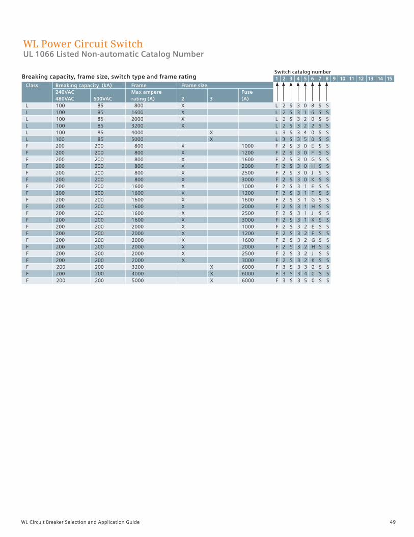
49WL Circuit Breaker Selection and Application Guide
Breaking capacity, frame size, switch type and frame rating
WL Power Circuit SwitchUL 1066 Listed Non-automatic Catalog Number
Switch catalog number 1 2 3 4 5 6 7 8 9 10 11 12 13 14 15 Class Breaking capacity (kA) Frame Frame size 240VAC Max ampere Fuse 480VAC 600VAC rating (A) 2 3 (A) L 100 85 800 X L 2 S 3 0 8 S S L 100 85 1600 X L 2 S 3 1 6 S S L 100 85 2000 X L 2 S 3 2 0 S S L 100 85 3200 X L 2 S 3 2 2 S S L 100 85 4000 X L 3 S 3 4 0 S S L 100 85 5000 X L 3 S 3 5 0 S S F 200 200 800 X 1000 F 2 S 3 0 E S S F 200 200 800 X 1200 F 2 S 3 0 F S S F 200 200 800 X 1600 F 2 S 3 0 G S S F 200 200 800 X 2000 F 2 S 3 0 H S S F 200 200 800 X 2500 F 2 S 3 0 J S S F 200 200 800 X 3000 F 2 S 3 0 K S S F 200 200 1600 X 1000 F 2 S 3 1 E S S F 200 200 1600 X 1200 F 2 S 3 1 F S S F 200 200 1600 X 1600 F 2 S 3 1 G S S F 200 200 1600 X 2000 F 2 S 3 1 H S S F 200 200 1600 X 2500 F 2 S 3 1 J S S F 200 200 1600 X 3000 F 2 S 3 1 K S S F 200 200 2000 X 1000 F 2 S 3 2 E S S F 200 200 2000 X 1200 F 2 S 3 2 F S S F 200 200 2000 X 1600 F 2 S 3 2 G S S F 200 200 2000 X 2000 F 2 S 3 2 H S S F 200 200 2000 X 2500 F 2 S 3 2 J S S F 200 200 2000 X 3000 F 2 S 3 2 K S S F 200 200 3200 X 6000 F 3 S 3 3 2 S S F 200 200 4000 X 6000 F 3 S 3 4 0 S S F 200 200 5000 X 6000 F 3 S 3 5 0 S S

50 WL Circuit Breaker Selection and Application Guide
Breaker ready-to-close auxiliary contacts
Shunt trip
sUndervoltage release (with or without time delay) or 2nd shunt trip
Breaker ready-to-close Breaker open/close auxiliary switches 1b contact 2a + 2b 4a + 4b 4NO+4NC
None X X B X C X D X X H X X I
Switch catalog number
Operation voltage Status AC DC contact None X 24 A 48 B 120 125 C 240 250 D 24 X E 48 X F 120 125 X G 240 250 X H
Operation voltage UVR UVR UVR 2nd shunt AC DC without delay with delay status contact 1 trip None X 24 X A 48 X B 120 125 X C 240 250 X D 48 X E 120 125 X F 240 250 X G 24 X H 48 X J 120 125 X K 240 250 X L 24 X X M 48 X X N 120 125 X X P 240 250 X X Q 48 X X R 125 X X S 120 250 X X T
WL Power Circuit SwitchUL 1066 Listed Non-automatic Catalog Number
1 2 3 4 5 6 7 8 9 10 11 12 13 14 15
1 Status contact only available when communication is not installed. Signal is sent via communication in lieu of status contact.

51WL Circuit Breaker Selection and Application Guide
WL Power Circuit SwitchUL 1066 Listed Non-automatic Catalog Number
Close coil, communications Close coil operation voltage
AC DC Modbus 1 PROFIBUS 1
None X X G 24 A 24 X N 48 B 48 X S 120 125 C 120 125 X W 240 250 D 240 250 X 2 X H 24 X P 48 X T 120 125 X Y 240 250 X 3
Charging motor operation voltage Motor cut-off Operations
AC DC switch counter None X 24 A 48 B 120 125 C 240 250 D 24 X E 48 X F 120 125 X G 240 250 X H 24 X J 48 X K 120 125 X L 240 250 X M 24 X X N 48 X X P 120 125 X X Q 240 250 X X R
Charging motor, motor switch, operations counterSwitch catalog number 1 2 3 4 5 6 7 8 9 10 11 12 13 14 15
1 Requires 24VDC power supply. BSS is included.

52 WL Circuit Breaker Selection and Application Guide
WL Power Circuit SwitchUL 1066 Listed Non-automatic Catalog Number
Switch catalog number 1 2 3 4 5 6 7 8 9 10 11 12 13 14 15
UL 1066 Listed Accessories External accessories Catalog number Single phase CTs for metering, 5A secondary Ratings – 800:5 WLG800NMCT23 Ratings – 1600:5 WLG1600NMCT23 Ratings – 2000:5 WLG2000NMCT23 Ratings – 3200:5 WLG3200NMCT23 Ratings – 4000:5 WLG4000NMCT23 Ratings – 5000:5 WLG5000NMCT23 Modified differential ground fault Modified differential GF (FS2 1200:1) Phase CT WLGMDGFCT2 Modified differential GF (FS3 1200:1) Phase CT WLGMDGFCT3 Modified differential GF (FS2, FS3 1200:1) Neutral CT WLNCT3CB 4-wire residual ground fault sensor Without copper bus adapters (pass-thru mount) - for 3” max bus bar WLNCT2 Without copper bus adapters (pass-thru mount) - for 3 - 5” max bus bar WLNCT3 With copper bus adapters for bus bar connection - for 3” max bus bar WLNCT2CB With copper bus adapters for bus bar connection - for 3 - 5” max bus bar WLNCT3CB Internal replacement current sensor kit Frame Size 2 Breaker WLCT2 Frame Size 3 Breaker WLCT3 Miscellaneous external accessories Crimp lugs for 10#AWG secondary wiring (package of 70) WL10RL Auxiliary contact on drawout breaker (knife block) WLCNMD 24V DC trip unit and communications power supply, 2.5A SITOP power, class 2 WLSITOP25 24V DC trip unit and communications power supply, 3.8A SITOP power, class 2 WLSITOP1
Key lock breaker Key lock breaker Padlock provisions for Padlock provisions OPEN position (lock OPEN position (lock OPEN and CLOSE for charging type – KIRK) 1 type – SUPERIOR)1 pushbuttons2 handle
None X X A X C X E X F X X G X X J X X S X X U X X V X X X W X X X Z
Switch locks
Miscellaneous options 3
Key lock breaker OPEN position (provision only) 2
None N X B
1 Custom key locks are not available and must be supplied by others. Order Key Lock Provisions if custom keys or keyed alike breakers are required. 2 Lock provided by others.3 If a breaker lock is chosen for Digit 14, a provision does not need to be ordered in Digit 15.
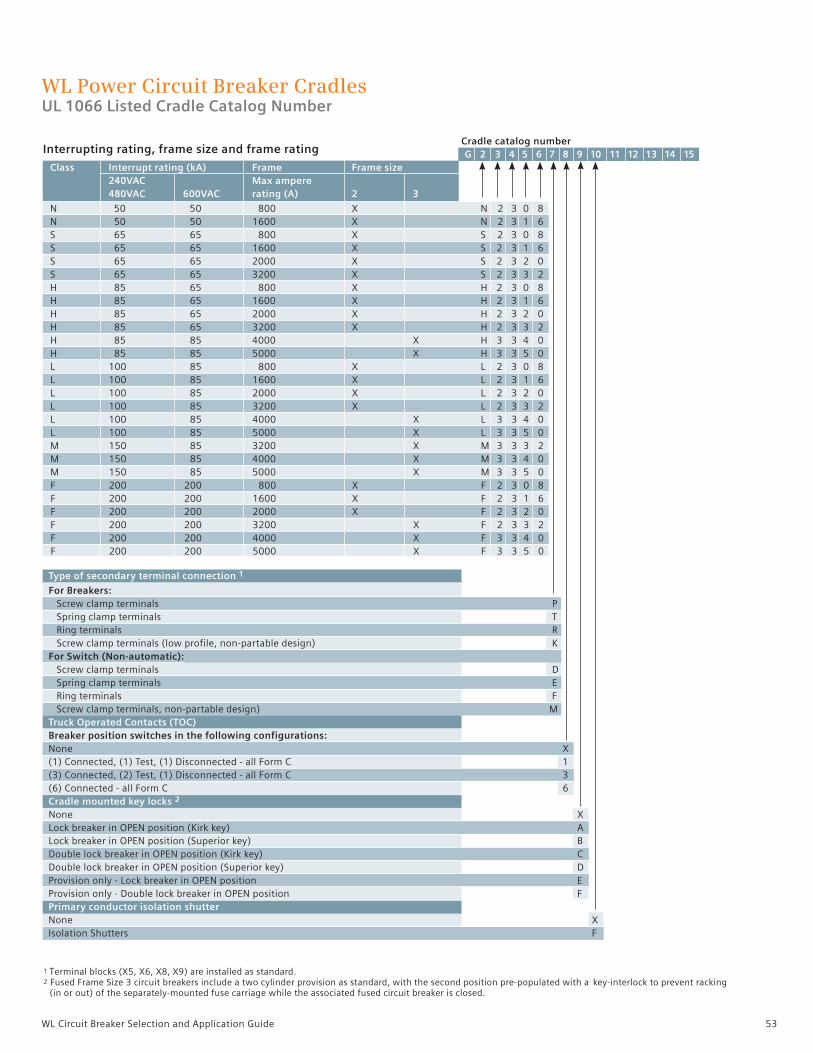
53WL Circuit Breaker Selection and Application Guide
WL Power Circuit Breaker CradlesUL 1066 Listed Cradle Catalog Number
Type of secondary terminal connection 1
For Breakers: Screw clamp terminals P Spring clamp terminals T Ring terminals R Screw clamp terminals (low profile, non-partable design) K For Switch (Non-automatic): Screw clamp terminals D Spring clamp terminals E Ring terminals F Screw clamp terminals, non-partable design) M Truck Operated Contacts (TOC) Breaker position switches in the following configurations: None X (1) Connected, (1) Test, (1) Disconnected - all Form C 1 (3) Connected, (2) Test, (1) Disconnected - all Form C 3 (6) Connected - all Form C 6 Cradle mounted key locks 2 None X Lock breaker in OPEN position (Kirk key) A Lock breaker in OPEN position (Superior key) B Double lock breaker in OPEN position (Kirk key) C Double lock breaker in OPEN position (Superior key) D Provision only - Lock breaker in OPEN position E Provision only - Double lock breaker in OPEN position F Primary conductor isolation shutter None X Isolation Shutters F
Cradle catalog number G 2 3 4 5 6 7 8 9 10 11 12 13 14 15 Class Interrupt rating (kA) Frame Frame size 240VAC Max ampere 480VAC 600VAC rating (A) 2 3
N 50 50 800 X N 2 3 0 8 N 50 50 1600 X N 2 3 1 6 S 65 65 800 X S 2 3 0 8 S 65 65 1600 X S 2 3 1 6 S 65 65 2000 X S 2 3 2 0 S 65 65 3200 X S 2 3 3 2 H 85 65 800 X H 2 3 0 8 H 85 65 1600 X H 2 3 1 6 H 85 65 2000 X H 2 3 2 0 H 85 65 3200 X H 2 3 3 2 H 85 85 4000 X H 3 3 4 0 H 85 85 5000 X H 3 3 5 0 L 100 85 800 X L 2 3 0 8 L 100 85 1600 X L 2 3 1 6 L 100 85 2000 X L 2 3 2 0 L 100 85 3200 X L 2 3 3 2 L 100 85 4000 X L 3 3 4 0 L 100 85 5000 X L 3 3 5 0 M 150 85 3200 X M 3 3 3 2 M 150 85 4000 X M 3 3 4 0 M 150 85 5000 X M 3 3 5 0 F 200 200 800 X F 2 3 0 8 F 200 200 1600 X F 2 3 1 6 F 200 200 2000 X F 2 3 2 0 F 200 200 3200 X F 2 3 3 2 F 200 200 4000 X F 3 3 4 0 F 200 200 5000 X F 3 3 5 0
Interrupting rating, frame size and frame rating
1 Terminal blocks (X5, X6, X8, X9) are installed as standard. 2 Fused Frame Size 3 circuit breakers include a two cylinder provision as standard, with the second position pre-populated with a key-interlock to prevent racking (in or out) of the separately-mounted fuse carriage while the associated fused circuit breaker is closed.

54 WL Circuit Breaker Selection and Application Guide
WL Power Circuit Breaker CradlesUL 1066 Listed Cradle Catalog Number
Cradle catalog number G 2 3 4 5 6 7 8 9 10 11 12 13 14 15 15
Arc chute covers
None X Arc chute covers (FS2 only – Except Class F) A Arc chute covers (FS3 only – Except Class F and M) B Door locks and mechanical interlock 1. Mechanical interlock with 2.0 meter Bowden cable 2. Locks cubicle door, when breaker is in connect position (FS2 and FS3) 3. Locks against racking breaker if the cubicle door is open (FS2 and FS3) 1 2 3 None X X M X A X C X X D X X X E X X G X X H Mechanism Operated Contacts (MOC) Breaker open/close auxiliary switches (4a & 4b) in the following positions: None X Test and Connect position (FS2 only) M Connect position (FS2 only) N Test and Connect position (FS3 only) P Connect position (FS3 only) Q Connector and heater options Standard rear connectors X Standard rear connectors and a cradle heater H Rotatable rear connectors (FS2, 2000A and below, N, S, & H Class) J Rotatable rear connectors and a cradle heater (FS2, 2000A and below, N, S, & H Class) K Future use Placeholder (required) N
UL 1066 Listed accessories Cradle accessories Catalog Number 3-phase metering CTs, cradle mounted (3 windows per CT) FS2 Ratings – 800:5 WLG8005MCT2 Ratings – 1600:5 WLG16005MCT2 Ratings – 2000:5 WLG20005MCT2 Ratings – 3200:5 WLG32005MCT2 FS3 Ratings – 3200:5 WLG32005MCT3 Ratings – 4000:5 WLG40005MCT3 Ratings – 5000:5 WLG50005MCT3

55WL Circuit Breaker Selection and Application Guide
WL BreakerApplication data
WL Secondary Terminal Assignments

56 WL Circuit Breaker Selection and Application Guide
WL Breaker General Wiring Schematic
X8 - 10
X8 9 -
BREAKER
L1
L2
L3
N
LINE (TOP FED)
LOAD (BOTTOM FED)
BONDING MUST BE UPSTREAM OF SENSOR
600V AC 3P, 4W:
WL CIRCUIT
TWISTED PAIR
P1
P2
NS
WL GF
S1-
S2+ TRIP UNIT
X8-10
X8-9
3P, 4W: 480V AC
- OR -
SEE DETAIL TOTHE RIGHT
X8-10 X8-9
N
NEUTRAL SENSOR
TWISTED PAIR
P1
P2
BO
TTO
M F
ED
SOU
RCE
TOP
FED
SOU
RCE
3P, 4W: 480V OR 600V AC
ETU745, ETU748, ETU776
METERING MODULE
BREAKER STATUS SENSOR (BSS) MODULE
0VDC
CUB-
CUB+
24VDC
Cu
bic
leB
us
A B C N
POTENTIAL TRANSFORMER INPUTS
X8-
8, N
X8-
7, L
3
X8-
6, L
2
X8-
5, L
1
INTERNAL WIRING INTERNAL WIRING
INTERNAL WIRING
S43 S42 S45
S40 S41 S44
WIRING IS CONTINUOUS IF NO METERING MODULE IS INSTALLED
WIRING IS CONTINUOUS IF NO BSS MODULE IS INSTALLED
CU
B+
CU
B-
24V
DC
0VD
C
CubicleBus
INTE
RNA
L W
IRIN
G
X8-
1
X8-
2
X8-
3
X8-
4

57WL Circuit Breaker Selection and Application Guide
WL
3. ALL GROUND FAULT WIRING TO BE SHIELDED TWISTED PAIR4. SHUNT TRIP CLEARING CONTACT ONLY WITH INTERMITTENT-DUTY SHUNT TRIPS ON FIRST SHUNT TRIP ONLY
2. ALL DEVICES SHOWN IN OPEN AND/OR DE-ENERGIZED STATE.1. COMPONENT PLACEMENT PER PANEL, SWITCHGEAR, OR SWITCHBOARD DRAWINGS.
NOTES:
F2
F6
24VDC
F7
S26
S22
X8-12
X9-7 X9-8 X9-9
X9-10 X9-11
X9-13 X9-14
X9-12
+
S23
S24
X8-14 X8-13
X9-1 X9-2 X9-3 X9-4 X9-5 X9-6
+
-
-
+
-
+
X8-11 X8-10 X8-9 X8-8 X8-7 X8-6 X8-5 X8-4 X8-3
+
-
0VDC
S1- S2+
X8-2 X8-1 -
+ CUB+
CUB-
X6-3
F4 "UVR td" F3 "UVR",
"QUICK OFF" F4 ONLY
X5 X9
MS12
S3/b
S4/b
S4/a
X5-7 X5-8
X5-5 X5-6
X5-3 X5-4
X5-1 X5-2
-
+
S2/b
S3/a
X5-14 X5-13 X5-12 X5-11 X5-10 X5-9
X6-1 X6-2
X6
TRIP UNIT POWER
POTENTIAL TRANSFORMER INPUTS120VAC SECONDARY EXTERNAL
X8
X7-
4
X7-
1 X
7-2
X7-
3
X7-
5 X
7-6
X7-
7 X
7-8
X7
-
+
S1/a
Y1
S1/b
S20
S2/a X6-4 X6-5
X6-7 X6-8
X6-6
X6-10 X6-9
X6-12 X6-11
-
+
X7-
9
F1 X6-14 X6-13
1 5
6 9
NEUTRAL SENSOR INPUTS
-
+ S1- S2+
GF SENSOR INPUTS
+
- (N)
(L) REMOTE RESET BELL ALARM AND TRIPPED INDICATOR 79
(N) - + (L)
FIRST SHUNT TRIP 52TC/86
AUX. SWITCH S4, NC, 52b
AUX. SWITCH S4, NO, 52a
AUX. SWITCH S3, NC, 52b
AUX. SWITCH S3, NO, 52a
OPTIONAL SWITCH BY CUSTOMER
+ (L)
- (N) UNDERVOLTAGE RELEASE (62/27)
EMERGENCY OPEN VIA UNDERVOLTAGE RELEASE (OPENS BREAKER ONLY WHEN UVR IS INSTALLED)
+ (L)
(N) - ELECTRIC SPRING CHARGING MOTOR 52M
+ (L) REMOTE CLOSING COIL 52CC
AUX. SWITCH S2, NO, 52a
AUX. SWITCH S2, NC, 52b
AUX. SWITCH S1, NC, 52b
AUX. SWITCH S1, NO, 52a
(N) -
"READY TO CLOSE" SIGNALING SWITCH 52LC
+ -
(L)
(N) SECOND SHUNT TRIP 52TC
MAG-LATCH FOR OPEN FUSE LOCKOUT (TO FUSE CARRIAGE)
OPEN FUSE LOCKOUT SWITCH S26
FIRST SHUNT TRIP SIGNALING SWITCH 52CS
SECOND SHUNT TRIP SIGNALING SWITCH S2CS
BELL ALARM/TRIP SIGNALING SWITCH 30, NC
BELL ALARM/TRIP SIGNALING SWITCH 30, NO
COM15 OR 16 COMM. MOD
COMM. MODULE LEAD WIRE FROM RJ45 PLUG
MODBUS OR PROFIBUS CONN.
FREE
CLO
SE 0
VD
C -
FREE
24V
DC
+
FREE
0V
DC
-
CLO
SE 2
4VD
C +
O
PEN
0V
DC
-
OPE
N 2
4VD
C +
CO
MM
ON
EN
AB
LE
DP
WRI
TE
INTERPOSING RELAYS FOR TRIP/CLOSE CONTROL VOLTAGES OTHER THAN 24VDC
K1 K2 X6-
7
X6-
8
X6-
14
X6-
13
DIRECT CONNECTION TO X6 TERMINAL STRIP FOR 24VDC
TRIP/CLOSE CONTROL VOLTAGE
K2 K1
+ (L) (N) - TRIP/CLOSE
CONTROL VOLTAGE
(N) -
CubicleBus MODULES
RJ45 X1 X2
RJ45
X3
1 2 3 4
RJ45 X1 X2
RJ45
X3
2 1 4 3
RJ45 X1
RJ45 X2
1 2 3 4
X3 X3
2 1 4 3
RJ45 X1 X2
RJ45 RJ45 X1
RJ45 X2
X3
1 2 3 4
INSTALL TERMINATING RESISTOR
(ZSI) ZONE SELECTIVE INTERLOCKING MODULE
MUST BE FIRST MODULE
0VDC (-)
24VDC (+)
0VDC (-)
24VDC (+) 24VDC (+)
0VDC (-)
24VDC (+)
0VDC (-)
0VD
C
CU
B-
CU
B+
24
VD
C
X8-
4
X8-
1 X
8-2
X8-
3
WHEN COM MODULE RJ45 CABLE IS CONNECTED TO FIRST CUBICLEBUS MODULE, X3-2 AND X3-3 CONNECTIONS ARE NOT REQUIRED, X3-1 AND X3-4 CONNECTIONS ONLY REQUIRED WHEN MORE THAN 2 CUBICLEBUS MODULES ARE INSTALLED. WITH NO COM MODULE, ALL X3 CONNECTIONS ARE REQUIRED.
DIGITAL OUTPUT MODULE WITH ROTARY SWITCH
DIGITAL OUTPUT MODULE CONFIGURABLE MODULE
ANALOG OUTPUT DIGITAL INPUT MODULE
WL BREAKER(SECONDARY TERMINALS)
4)
WL Breaker General Wiring Schematic

58 WL Circuit Breaker Selection and Application Guide
Ground Fault ProtectionWhen optional ground fault is selected, the trip unit detects fault currents that flow to ground and represent a fire hazard to the system. The adjustable time delay allows selective staggering of consecutively arranged circuit breakers.
When setting the parameters of the trip unit, a selection can be made between alarm and trip if the set current value is exceeded. The cause of the trip is displayed on an LED when the query button is pressed.
ModulesThe trip unit versions ETU745, ETU748, and ETU776 can be retrofit-ted with a ground fault protection module.
Two versions of the optional ground fault module can be ordered:• Trip and Alarm• Alarm only
Ground Fault Measuring MethodsResidual sensing of the ground fault current
The trip unit calculates the ground fault current by vectorial current summation of the 3- phase currents and the neutral conductor current.
Direct measurement of the ground fault current
A current transformer with the transformer ratio 1200A : 1A is used to measure the ground fault current. The transformer can be installed directly in the grounded star point of a transformer.
SettingThe ground fault module can be set depending on the measuring method (see above):
Measuring method 1: in position sum IMeasuring method 2: in position G.
With trip unit ETU776, this setting is implemented via the display and key pad or communications.
Ground Fault Protection with I2t Characteristic CurveAll versions of the ground fault modules are delivered with an I2t or fixed delay.
Modules are available in either Alarm only or Alarm and Trip functions.
Residual sensing of the ground fault current
Direct measurement of the ground fault current
Ground fault module GFM A 745-748 Ground fault module GFM AT 745-748
Ground fault module GFM A 776 Ground fault module GFM AT 776
WL Breaker Ground Fault Setting
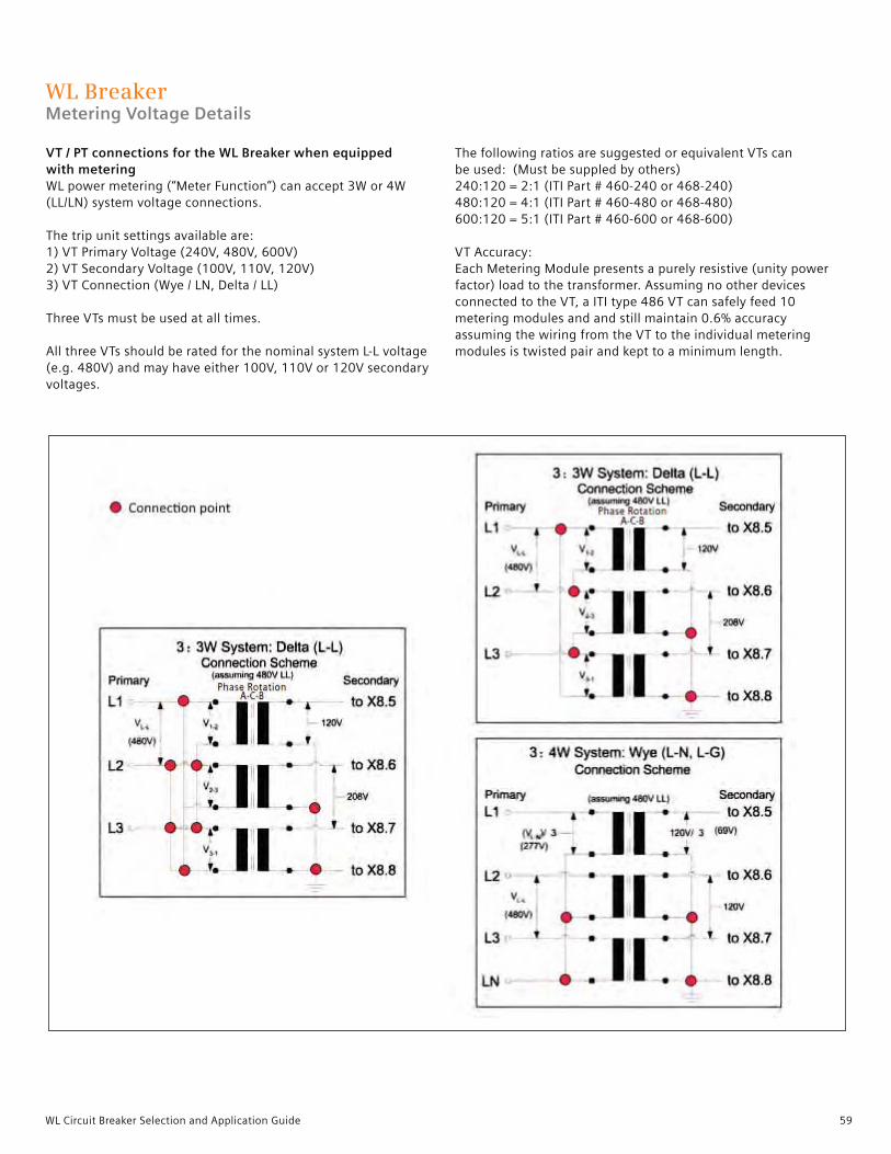
59WL Circuit Breaker Selection and Application Guide
VT / PT connections for the WL Breaker when equipped with metering WL power metering (“Meter Function”) can accept 3W or 4W (LL/LN) system voltage connections.
The trip unit settings available are:1) VT Primary Voltage (240V, 480V, 600V)2) VT Secondary Voltage (100V, 110V, 120V)3) VT Connection (Wye / LN, Delta / LL)
Three VTs must be used at all times.
All three VTs should be rated for the nominal system L-L voltage(e.g. 480V) and may have either 100V, 110V or 120V secondaryvoltages.
The following ratios are suggested or equivalent VTs can be used: (Must be suppled by others)240:120 = 2:1 (ITI Part # 460-240 or 468-240)480:120 = 4:1 (ITI Part # 460-480 or 468-480)600:120 = 5:1 (ITI Part # 460-600 or 468-600)
VT Accuracy:Each Metering Module presents a purely resistive (unity powerfactor) load to the transformer. Assuming no other devicesconnected to the VT, a ITI type 486 VT can safely feed 10metering modules and and still maintain 0.6% accuracyassuming the wiring from the VT to the individual meteringmodules is twisted pair and kept to a minimum length.
WL Breaker Metering Voltage Details

60 WL Circuit Breaker Selection and Application Guide
Low Voltage Circuit Breaker UL489 Fixed-mount Breaker Dimensions
Frame size 1

61WL Circuit Breaker Selection and Application Guide
Frame size 1 Horizontal Connectors
Top view
Bottom view
Low Voltage Circuit Breaker UL489 Fixed-mount Breaker Dimensions

62 WL Circuit Breaker Selection and Application Guide
Low Voltage Circuit Breaker UL489 Fixed-mount Breaker Dimensions
Frame Size 1 Rear Vertical Connectors
Top view
Rear view

63WL Circuit Breaker Selection and Application Guide
Low Voltage Circuit Breaker UL489 Fixed-mount Breaker Dimensions
Frame Size 1 Front Connectors
Top view
Front view

64 WL Circuit Breaker Selection and Application Guide
Low Voltage Circuit Breaker UL489 Fixed-mount Breaker Dimensions
Frame Size 1 Front Connectors and Lugs
Top view
Front view

65WL Circuit Breaker Selection and Application Guide
Low Voltage Circuit Breaker UL489 Fixed-mount Breaker Dimensions
Fixed Size 1 Door Cut-outs

66 WL Circuit Breaker Selection and Application Guide
Low Voltage Circuit Breaker UL489 Fixed-mount Breaker Dimensions
Frame Size 2
Interrupting class Dimension B Dimension C Dimension D
S/L 15.85 [402.5] 18.70 [475.0] 22.30 [566.5]
C 17.80 [452.10] 18.70 [475.0] 25.20 [640.0]
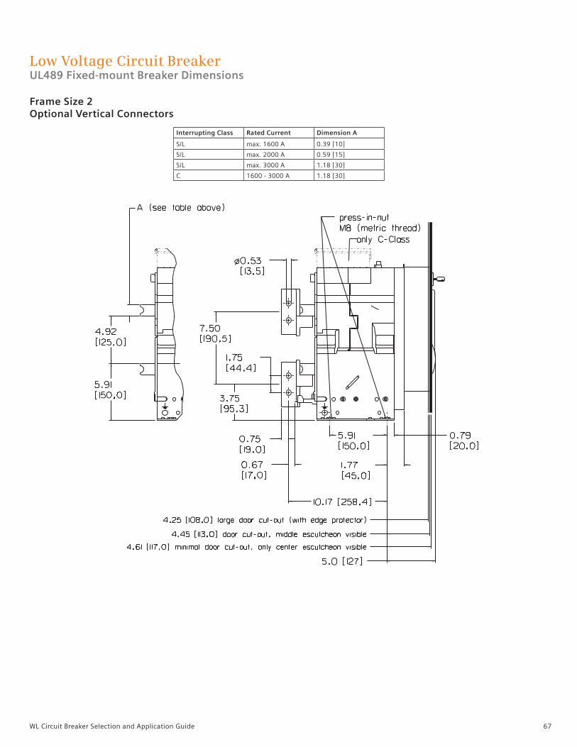
67WL Circuit Breaker Selection and Application Guide
Low Voltage Circuit Breaker UL489 Fixed-mount Breaker Dimensions
Frame Size 2Optional Vertical Connectors
Interrupting Class Rated Current Dimension A
S/L max. 1600 A 0.39 [10]
S/L max. 2000 A 0.59 [15]
S/L max. 3000 A 1.18 [30]
C 1600 - 3000 A 1.18 [30]

68 WL Circuit Breaker Selection and Application Guide
Low Voltage Circuit Breaker UL489 Fixed-mount Breaker Dimensions
Frame Size 2 Optional Vertical Connectors
Top view
Rear view
Rated Current Dimension A
max. 1600 A 0.39 [10]
max. 2000 A 0.59 [15]
max. 3000 A 1.18 [30]
C-class always 1.18 [30]

69WL Circuit Breaker Selection and Application Guide
Low Voltage Circuit Breaker UL489 Fixed-mount Breaker Dimensions
Frame Size 2 Front Connectors
Front view
LH side view
Rated Current Dimension A
max. 1600 A 0.39 [10]
max. 2000 A 0.79 [20]
max. 2500 A 0.79 [20]

70 WL Circuit Breaker Selection and Application Guide
Low Voltage Circuit Breaker UL489 Fixed-mount Breaker Dimensions
Frame Size 2 3000A Front Connectors

71WL Circuit Breaker Selection and Application Guide
Low Voltage Circuit Breaker UL489 Fixed-mount Breaker Dimensions
LH side view
Frame Size 3

72 WL Circuit Breaker Selection and Application Guide
Low Voltage Circuit Breaker UL489 Fixed-mount Breaker Dimensions
Frame Size 3 Vertical Connectors and Horizontal Stabs
Top view
Top view
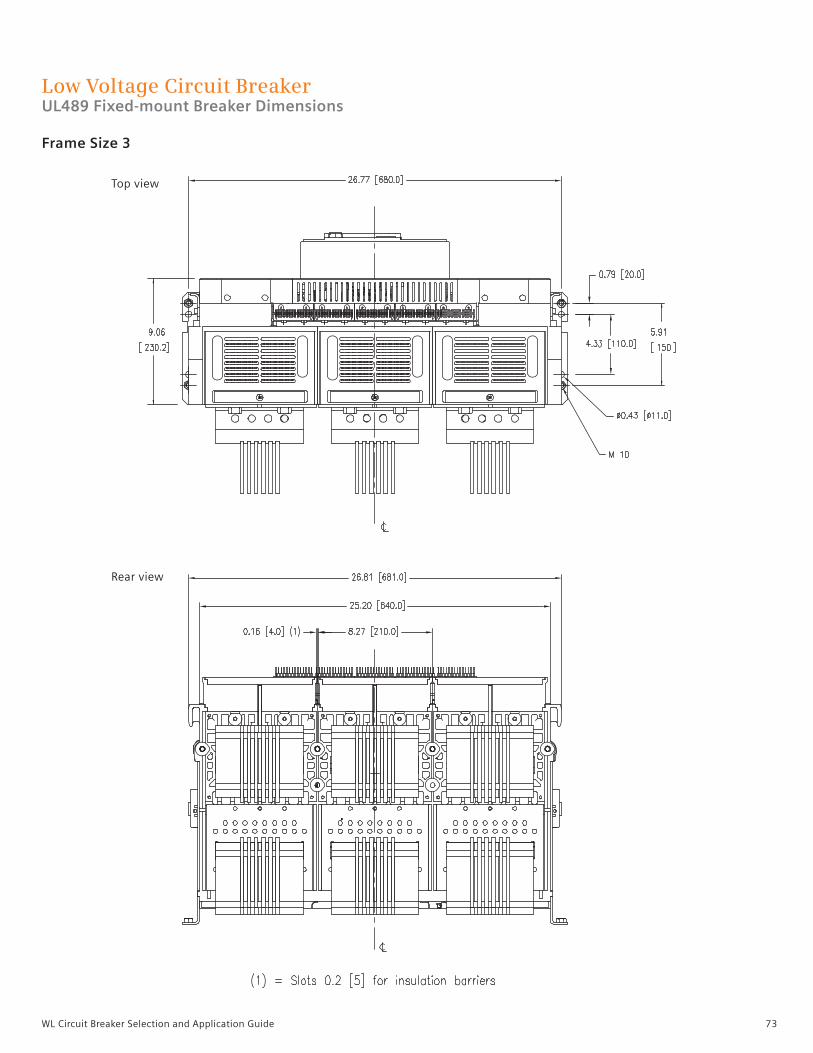
73WL Circuit Breaker Selection and Application Guide
Low Voltage Circuit Breaker UL489 Fixed-mount Breaker Dimensions
Frame Size 3
Top view
Rear view

74 WL Circuit Breaker Selection and Application Guide
LH side view
Front view
Frame Size 3 5000A Vertical Connectors
Low Voltage Circuit Breaker UL489 Fixed-mount Breaker Dimensions

75WL Circuit Breaker Selection and Application Guide
Frame Size 2 and 3 Door Cut-outs
Low Voltage Circuit Breaker UL489 Fixed-mount Breaker Dimensions
Door cut-out and mounting holes for Door Sealing Frame
Door cut-out (Middle escutcheon visible)
1) Breaker mounting surface. 2) Center of breaker front panel.3) Drill eight holes for mounting door sealing frame.
Door cut-out (after mounting Door Sealing Frame)
Minimal door cut-out (Only center eustcheon visible)

76 WL Circuit Breaker Selection and Application Guide
Low Voltage Circuit Breaker UL489 Draw-out Breaker Dimensions
Frame Size 1

77WL Circuit Breaker Selection and Application Guide
Rear view
Top view
Low Voltage Circuit Breaker UL489 Draw-out Breaker Dimensions
Frame Size 1Vertical Connectors

78 WL Circuit Breaker Selection and Application Guide
Low Voltage Circuit Breaker UL489 Draw-out Breaker Dimensions
Frame Size 1
Bottom view
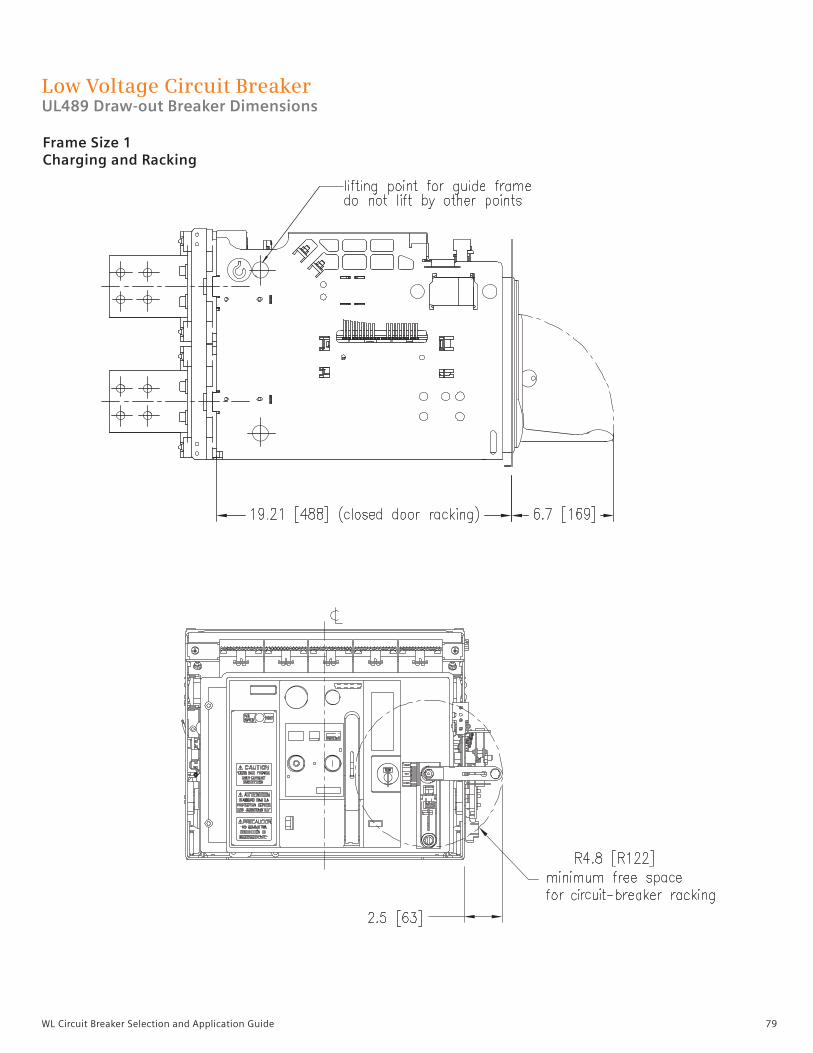
79WL Circuit Breaker Selection and Application Guide
Low Voltage Circuit Breaker UL489 Draw-out Breaker Dimensions
Frame Size 1 Charging and Racking

80 WL Circuit Breaker Selection and Application Guide
Low Voltage Circuit Breaker UL489 Draw-out Breaker Dimensions
Frame Size 1 Plexiglass Cover

81WL Circuit Breaker Selection and Application Guide
Low Voltage Circuit Breaker UL489 Draw-out Breaker Dimensions
Frame Size 1 Door Cut-outs

82 WL Circuit Breaker Selection and Application Guide
Low Voltage Circuit Breaker UL489 Draw-out Breaker Dimensions
Frame Size 2

83WL Circuit Breaker Selection and Application Guide
Low Voltage Circuit Breaker UL489 Draw-out Breaker Dimensions
Frame Size 2
2500/3000A 2000A 800/1200/1600A

84 WL Circuit Breaker Selection and Application Guide
Note:Rotatable main bus connectors are only available under the following conditions:(1) Only acceptable for FS II 800A-2000A Frame Sizes(2) Only acceptable for short circuit ratings of 85KAIC or less
Frame Size 2 Vertical Connectors and Optional Horizontal Connectors
Low Voltage Circuit Breaker UL489 Draw-out Breaker Dimensions
Horizontal Main Bus Connectors
Horizontal Main Bus Connectors
Vertical Main Bus Connectors
Vertical Main Bus Connectors

85WL Circuit Breaker Selection and Application Guide
Low Voltage Circuit Breaker UL489 Draw-out Breaker Dimensions
Frame Size 2 Charging, Racking and Draw-out
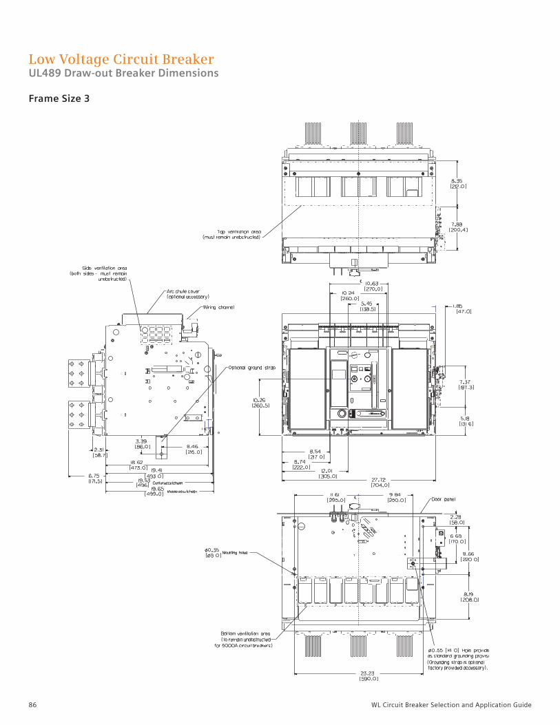
86 WL Circuit Breaker Selection and Application Guide
Low Voltage Circuit Breaker UL489 Draw-out Breaker Dimensions
Frame Size 3
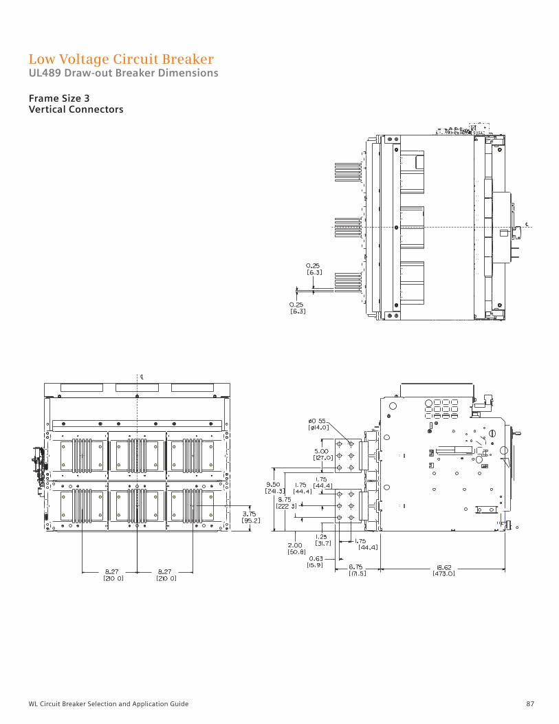
87WL Circuit Breaker Selection and Application Guide
Low Voltage Circuit Breaker UL489 Draw-out Breaker Dimensions
Frame Size 3 Vertical Connectors

88 WL Circuit Breaker Selection and Application Guide
Low Voltage Circuit Breaker UL489 Draw-out Breaker Dimensions
Frame Size 3 Charging, Racking and Draw-out

89WL Circuit Breaker Selection and Application Guide
Low Voltage Circuit Breaker UL489 Draw-out Breaker Dimensions
Frame Size 2 and 3 Door Cut-outs
1
71 1
Door cut-out and mounting holes for Door Sealing Frame
Door cut-out (Middle escutcheon visible)
1) Mounting surface of the circuit breaker or cradle. 2) Center of breaker front panel.3) Drill eight holes for mounting door sealing frame.
Door cut-out (after mounting Door Sealing Frame)
Minimal door cut-out (Only center eustcheon visible)
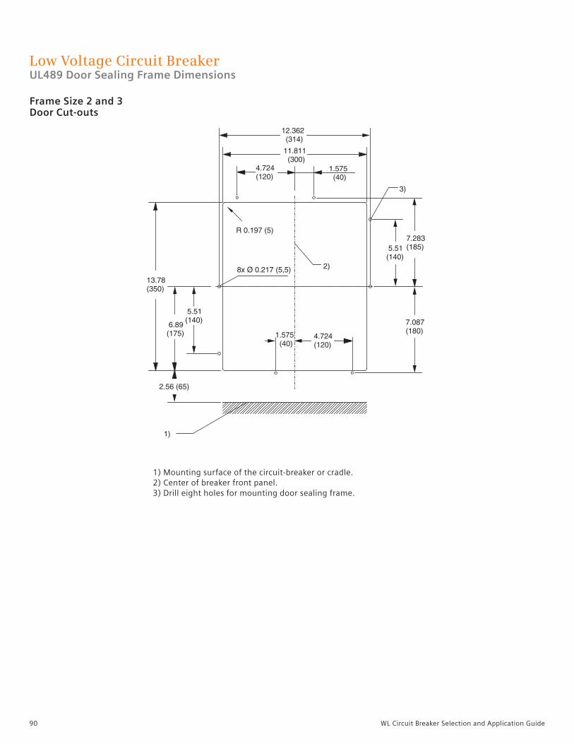
90 WL Circuit Breaker Selection and Application Guide
Low Voltage Circuit Breaker UL489 Door Sealing Frame Dimensions
Frame Size 2 and 3 Door Cut-outs
1) Mounting surface of the circuit-breaker or cradle. 2) Center of breaker front panel.3) Drill eight holes for mounting door sealing frame.

91WL Circuit Breaker Selection and Application Guide
Low Voltage Circuit Breaker UL 1066 Draw-out Non-fused Breaker Dimensions
Frame Size 2

92 WL Circuit Breaker Selection and Application Guide
Low Voltage Circuit Breaker UL 1066 Draw-out Non-fused Breaker Dimensions
Frame Size 2
3200A 2000A 800/1600A

93WL Circuit Breaker Selection and Application Guide
Low Voltage Circuit Breaker UL 1066 Draw-out Non-fused Breaker Dimensions
Frame Size 2
Note:Rotatable main bus connectors are only available under the following conditions:(1) Only acceptable for FS2 800A – 2000A Frame Sizes(2) Only acceptable for short circuit ratings of 85kAIC or less
Horizontal MainBus Connectors
Horizontal MainBus Connectors
Vertical MainBus Connectors
Vertical MainBus Connectors

94 WL Circuit Breaker Selection and Application Guide
Low Voltage Circuit Breaker UL 1066 Draw-out Non-fused Breaker Dimensions
Frame Size 2 Charging, Racking and Draw-out

95WL Circuit Breaker Selection and Application Guide
Low Voltage Circuit Breaker UL 1066 Draw-out Fused Breaker Dimensions
Frame Size 2

96 WL Circuit Breaker Selection and Application Guide
Low Voltage Circuit Breaker UL 1066 Draw-out Fused Breaker Dimensions
Frame Size 2

97WL Circuit Breaker Selection and Application Guide
Low Voltage Circuit Breaker UL 1066 Draw-out Fused Breaker Dimensions
Frame Size 2 Charging, Racking and Draw-out
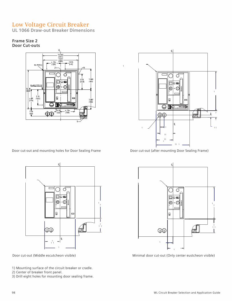
98 WL Circuit Breaker Selection and Application Guide
Low Voltage Circuit Breaker UL 1066 Draw-out Breaker Dimensions
Frame Size 2 Door Cut-outs
11 1
711
1
11
1
1
1
1 1
7
1
11 1
1
1
17
71 1
17
71 1
Door cut-out and mounting holes for Door Sealing Frame
Door cut-out (Middle escutcheon visible)
1) Mounting surface of the circuit breaker or cradle. 2) Center of breaker front panel.3) Drill eight holes for mounting door sealing frame.
Door cut-out (after mounting Door Sealing Frame)
Minimal door cut-out (Only center eustcheon visible)

99WL Circuit Breaker Selection and Application Guide
Low Voltage Circuit Breaker UL 1066 Draw-out Non-fused Breaker Dimensions
Frame Size 3

100 WL Circuit Breaker Selection and Application Guide
Low Voltage Circuit Breaker UL 1066 Draw-out Non-fused Breaker Dimensions
Frame Size 3

101WL Circuit Breaker Selection and Application Guide
Low Voltage Circuit Breaker UL 1066 Draw-out Non-fused Breaker Dimensions
Frame Size 3
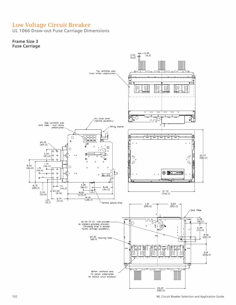
102 WL Circuit Breaker Selection and Application Guide
Low Voltage Circuit Breaker UL 1066 Draw-out Fuse Carriage Dimensions
Frame Size 3Fuse Carriage

103WL Circuit Breaker Selection and Application Guide
Low Voltage Circuit Breaker UL 1066 Draw-out Fuse Carriage Dimensions
Frame Size 3Fuse Carriage Racking

104 WL Circuit Breaker Selection and Application Guide
Low Voltage Circuit Breaker UL 1066 Door Sealing Frame Dimensions
Frame Size 3 Door Cut-outs
Door cut-out and mounting holes for Door Sealing Frame
Door cut-out (Middle escutcheon visible)
1) Mounting surface of the circuit breaker or cradle. 2) Center of breaker front panel.3) Drill eight holes for mounting door sealing frame.
Door cut-out (after mounting Door Sealing Frame)
Minimal door cut-out (Only center eustcheon visible)

105WL Circuit Breaker Selection and Application Guide
Low Voltage Circuit Breaker UL 1066 Draw-out Dimensions
Frame Size 2 and 3 Door Cut-outs
1) Mounting surface of the circuit-breaker or cradle. 2) Center of breaker front panel.3) Drill eight holes for mounting door sealing frame.

106 WL Circuit Breaker Selection and Application Guide
WL Spare/Replacement PartsTrip Units and Rating Plugs
1 Optional GF module sold separately.2 Metering function and ETU776 requires 24VDC supply.
ETU 745 ETU 748 ETU 776
Rating plug
Catalog Ampere Catalog Ampere Catalog Ampere Catalog Ampere number rating number rating number rating number rating
WLRP200 200A WLRP400 400A WLRP800 800A WLRP2500 2500A WLRP225 225A WLRP450 450A WLRP1000 1000A WLRP3000 3000A WLRP250 250A WLRP500 500A WLRP1200 1200A WLRP3200 3200A WLRP300 300A WLRP600 600A WLRP1250 1250A WLRP4000 4000A WLRP315 315A WLRP630 630A WLRP1600 1600A WLRP5000 5000A WLRP350 350A WLRP700 700A WLRP2000 2000A
ETU catalog Trip unit Protective Replacement Ground Ground fault number functions settings LCD displays fault alarm alarm and trip
WLETU745 LSI WLTUSC55 WLLCD48 WLGFA48 WLGFM48 WLETU748 LS WLTUSC55 WLLCD48 WLGFA48 WLGFM48 WLETU776 LSI WLTUSC76 Not replaceable WLGFA76 WLGFM76 Trip unit with metering function WLETU745MP LSI WLTUSC76 WLLCD48 WLGFA48 WLGFM48 WLETU748MP LS WLTUSC76 WLLCD48 WLGFA48 WLGFM48 WLETU776MP LSI WLTUSC76 Not replaceable WLGFA76 WLGFM76
Overload ProtectionL – Long Time Pick-up and Delay S – Short Time Pick-up and DelayI – Instantaneous Trip G – Ground Fault Pick-up and Delay (Accessory sold separately)
Rating plug
GFM A 745-748 GFM AT 745-748 GFM A 776 GFM AT 776
1
1
1
2
1
2
1
2
2
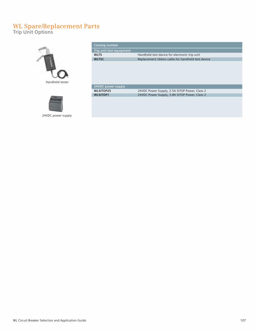
107WL Circuit Breaker Selection and Application Guide
WL Spare/Replacement PartsTrip Unit Options
Handheld tester
24VDC power supply
Catalog number
Trip unit test equipment WLTS Handheld test device for electronic trip unit WLTSC Replacement ribbon cable for handheld test device
24VDC power supply WLSITOP25 24VDC Power Supply, 2.5A SITOP Power, Class 2 WLSITOP1 24VDC Power Supply, 3.8A SITOP Power, Class 2

108 WL Circuit Breaker Selection and Application Guide
WL Spare/Replacement PartsSecondary Disconnects
1
1
1
1
1
1
Trip Units
Catalog number
WLGAUXPLUGP Screw connection for bare wire WLGAUXPLUGL Low Profile screw connection base wire Draw-out breaker only WLGAUXPLUGT Tension spring connection for bare wire WLGAUXPLUGR Screw connection for ring terminals Secondary disconnect breaker frame mount WLCNMD Knife blade contact block WLTERMBLKUL Pull Apart Terminal Block (UL 489 only) w/1.0mm leads WLCNMDA Extends height of secondary disconnect Secondary disconnect coding kit (UL489 only) WLCODEKITUL Secondary disconnect coding kit for fixed mounted breaker WL crimp lugs
WL10RL For use with WLGAUXPLUGR
1
Compression screwconnector
WLGAUXPLUGP
Spring loadconnector
WLGAUXPLUGT
Ring lugconnector
WLGAUXPLUGR
Low-profile screw connectorWLGAUXPLUGL
Knife Blade Contact BlockWLCNMD
Extends Height of WLCNMDWLCNMDA
Coding KitWLCODEKITUL
WLTERMBLKUL
1

109WL Circuit Breaker Selection and Application Guide
WL Spare/Replacement PartsCradle Frame Accessories
1
1
3
4
2
Catalog number
Stationary primary bus-bar disconnect terminals consists of 1 bus-bar pole only) WLGST15123LI FS1 800/1200A Line side stab tip WLGST10163LL FS2 800/1200/1600A Line and load side stab tip WLGST15203LL FS2 1200A Line and load side stab tip – FS1 800/1200 Load Side WLGST30323LL FS2 C-Class 1600/2000/2500/3000A Line and load stab tip WLGST30503LL FS3 4000/5000A Line and load side stab tip WLGST10163LD FS2 800/1200/1600A Load side stab tip WLGST15203LD FS2 2000A – 800/1200A Load side stab tip Cradle arc chute cover WLGARC1UL UL489 FS1, S, H, L WLGARC2UL UL489 FS2, S, L (not for Class C) WLGARC2 ANSI FS2, N, S, H, L WLGARC3 ANSI/UL489 FS2, H, L, F WLGARCF2 ANSI/UL489 FS2, Fused cradle MOC – Mechanism operated contacts (for draw-out breaker) WLMOC 4NO + 4NC Test and connect position FS1 and FS2 WLMOCC 4NO + 4NC Connect position only FS1 and FS2 WLMOC3 4NO + 4NC Test and connect position FS3 WLMOCC3 4NO + 4NC Connect position only FS3 (for fixed mounted circuit breakers) WLMOCUL1 4NO + 4NC FS1 WLMOCUL 4NO + 4NC FS2 TOC – Truck operated contacts WLGSGSW111 1 form C Disconnect, test and connect positions WLGSGSW321 1 form C Disconnect, 2 form C in test, 3 form C in connect WLGSGSW6 6 form in connect position Isolation shutters WLG3SHUT1L FS1 3-Pole Shutter for Class S,H,L WLG3SHUT2L FS2 3-Pole Shutter for Class N,S,H,L WLG3SHUT2F FS2 3-Pole Shutter for Class F WLG3SHUT2M FS2 3-Pole Shutter for Class C WLG3SHUT3L FS3 3-Pole Shutter for Class L,F,H WLG3SHUT3M FS3 3-Pole Shutter for Class C,M WLG3SHUT3FC FS3 3-Pole Shutter for Fuse Carriage WLG4SHUT2L FS2 4-Pole Shutter for Class S,H,L WLG4SHUT3L FS3 4-Pole Shutter for Class H,L
23
4
Arc Chute Louvers
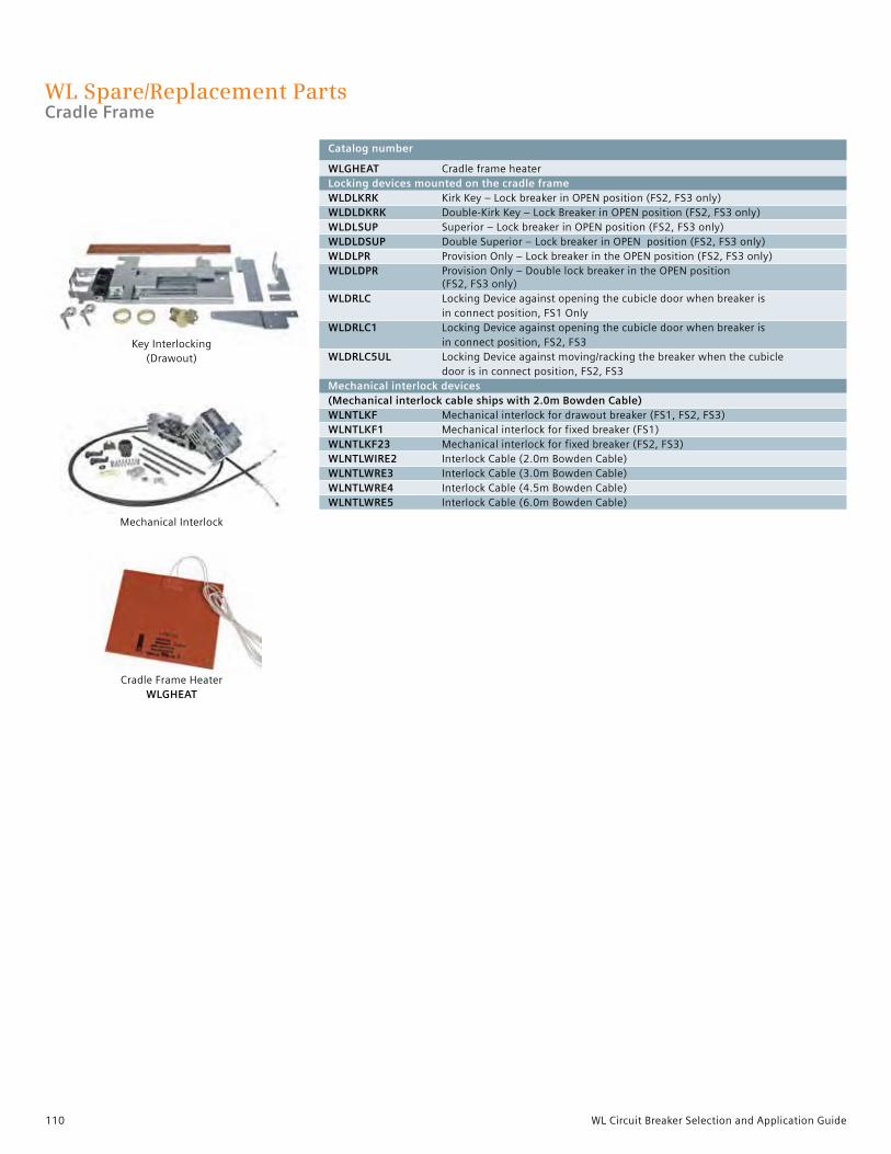
110 WL Circuit Breaker Selection and Application Guide
WL Spare/Replacement PartsCradle Frame
Catalog number
WLGHEAT Cradle frame heater Locking devices mounted on the cradle frame WLDLKRK Kirk Key – Lock breaker in OPEN position (FS2, FS3 only) WLDLDKRK Double-Kirk Key – Lock Breaker in OPEN position (FS2, FS3 only) WLDLSUP Superior – Lock breaker in OPEN position (FS2, FS3 only) WLDLDSUP Double Superior – Lock breaker in OPEN position (FS2, FS3 only) WLDLPR Provision Only – Lock breaker in the OPEN position (FS2, FS3 only) WLDLDPR Provision Only – Double lock breaker in the OPEN position (FS2, FS3 only) WLDRLC Locking Device against opening the cubicle door when breaker is in connect position, FS1 Only WLDRLC1 Locking Device against opening the cubicle door when breaker is in connect position, FS2, FS3 WLDRLC5UL Locking Device against moving/racking the breaker when the cubicle door is in connect position, FS2, FS3 Mechanical interlock devices (Mechanical interlock cable ships with 2.0m Bowden Cable) WLNTLKF Mechanical interlock for drawout breaker (FS1, FS2, FS3) WLNTLKF1 Mechanical interlock for fixed breaker (FS1) WLNTLKF23 Mechanical interlock for fixed breaker (FS2, FS3) WLNTLWIRE2 Interlock Cable (2.0m Bowden Cable) WLNTLWRE3 Interlock Cable (3.0m Bowden Cable) WLNTLWRE4 Interlock Cable (4.5m Bowden Cable) WLNTLWRE5 Interlock Cable (6.0m Bowden Cable)
Mechanical Interlock
Cradle Frame HeaterWLGHEAT
Key Interlocking(Drawout)

111WL Circuit Breaker Selection and Application Guide
WL Spare/Replacement PartsMetering CT Units
Catalog number Frame Ratio
WLG8005MCT1 FS1 800:5 WLG12005MCT1 FS1 1200:5 WLG8005MCT2 FS2 800:5 WLG10005MCT2 FS2 1000:5 WLG12005MCT2 FS2 1200:5 WLG16005MCT2 FS2 1600:5 WLG20005MCT2 FS2 2000:5 WLG30005MCT2 FS2 3000:5 WLG32005MCT2 FS2 3200:5 WLG20005MCT3 FS3 2000:5 WLG30005MCT3 FS3 3000:5 WLG32005MCT3 FS3 3200:5 WLG40005MCT3 FS3 4000:5 WLG50005MCT3 FS3 5000:5
Single phase metering CT
Catalog number Ratio
WLG800NMCT23 800:5 WLG1200NMCT23 1200:5 WLG1600NMCT23 1600:5 WLG2000NMCT23 2000:5 WLG3000NMCT23 3000:5 WLG3200NMCT23 3200:5 WLG4000NMCT23 4000:5 WLG5000NMCT23 5000:5
3 phase metering CT, guide frame mounted

112 WL Circuit Breaker Selection and Application Guide
WL Spare/Replacement PartsGround Fault and Current Sensors
Catalog number
Modified differential ground fault for source ground return
WLGMDGFCT2 FS2 1200:1 3 phase cradle mount WLGMDGFCT3 FS3 1200:1 3 phase cradle mount WLGNMDGCT23 Iron core neutral sensor 1200:1 1 phase bus mount
External neutral CT for 4 wire residual ground fault
WLNCT2 3” Without copper bus adapter (pass-thru mount) WLNCT3 3 – 5” max. bus-bar size Without copper bus adapter (pass-thru mount)
WLNCT2CB For 3” With copper bus adapter for bus connection WLNCT3CB For 3” – 5” max. bus-bar size With copper bus adapter for bus connection
Neutral Sensor
Neutral Sensor withBus Connector
Modified differential CT

113WL Circuit Breaker Selection and Application Guide
WL Spare/Replacement PartsCircuit Breaker Accessories
Catalog number
Shunt trip release WLST24 Shunt trip 24VDC, 3-cycle, momentary duty WLST48 Shunt trip 48VDC, 3-cycle, momentary duty WLST120 Shunt trip 125VDC / 120VAC, 3-cycle, momentary duty WLST240 Shunt trip 250VDC / 240VAC, 3-cycle, momentary duty WLSTCD24 Shunt trip 24VDC, continuous duty WLSTCD48 Shunt trip 48VDC, continuous duty WLSTCD120 Shunt trip 125VDC / 120VAC, continuous duty WLSTCD240 Shunt trip 250VDC / 240VAC, continuous duty (signal contactor 1st Shunt Trip) WLSTC Shunt trip “NO” switch - 3A @ 240VAC (signal contactor second Shunt Trip ) WLUVRC Undervoltage trip “NO” switch - 3 @ 240VAC Auxiliary signaling switch WLAS2 2 NO & 2 NC contacts WLAS4 4 NO & 4 NC contacts
Ready-to-close signal switch WLRTCS Ready-to-close contact, 1 NO, 4A @ 240VAC
Bell alarm Remote reset solenoid for bell-alarm and trip indicator WLRSET24 Bell alarm reset coil 24VDC WLRSET48 Bell alarm reset coil 48VDC WLRSET120 Bell alarm reset coil 125VDC / 120VAC WLRSET240 Bell alarm reset coil 250VDC / 240VAC WLBA Bell alarm - Form “C” - 1NO/1NC contact
Operation Counter Available ONLY w/ spring charging motor option WLNUMCNT Mechanical operation counter
Auxiliary Contact
Shunt Trip Coil
Ready-to-Close Contact
Bell Alarm Reset Coil
Bell Alarm Contacts
Operations Counter
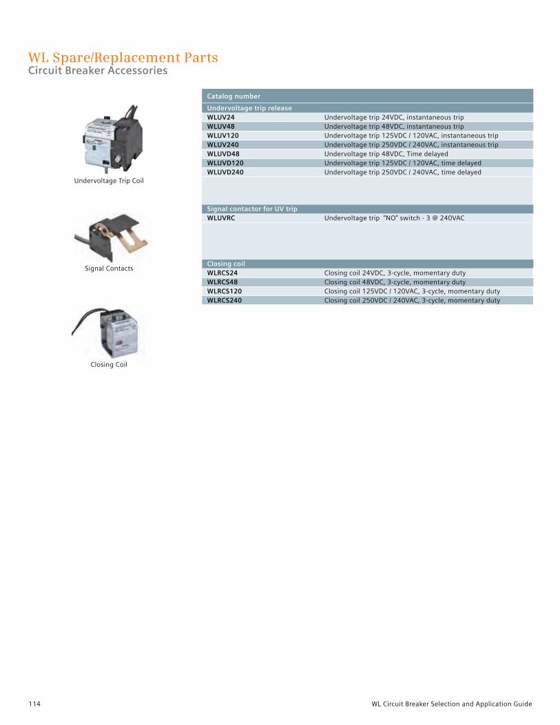
114 WL Circuit Breaker Selection and Application Guide
WL Spare/Replacement PartsCircuit Breaker Accessories
Catalog number
Undervoltage trip release WLUV24 Undervoltage trip 24VDC, instantaneous trip WLUV48 Undervoltage trip 48VDC, instantaneous trip WLUV120 Undervoltage trip 125VDC / 120VAC, instantaneous trip WLUV240 Undervoltage trip 250VDC / 240VAC, instantaneous trip WLUVD48 Undervoltage trip 48VDC, Time delayed WLUVD120 Undervoltage trip 125VDC / 120VAC, time delayed WLUVD240 Undervoltage trip 250VDC / 240VAC, time delayed
Signal contactor for UV trip WLUVRC Undervoltage trip “NO” switch - 3 @ 240VAC
Closing coil WLRCS24 Closing coil 24VDC, 3-cycle, momentary duty WLRCS48 Closing coil 48VDC, 3-cycle, momentary duty WLRCS120 Closing coil 125VDC / 120VAC, 3-cycle, momentary duty WLRCS240 Closing coil 250VDC / 240VAC, 3-cycle, momentary duty
Undervoltage Trip Coil
Signal Contacts
Closing Coil
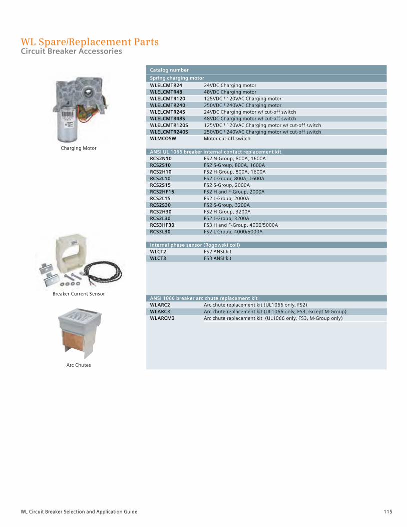
115WL Circuit Breaker Selection and Application Guide
Catalog number
Spring charging motor
WLELCMTR24 24VDC Charging motor WLELCMTR48 48VDC Charging motor WLELCMTR120 125VDC / 120VAC Charging motor WLELCMTR240 250VDC / 240VAC Charging motor WLELCMTR24S 24VDC Charging motor w/ cut-off switch WLELCMTR48S 48VDC Charging motor w/ cut-off switch WLELCMTR120S 125VDC / 120VAC Charging motor w/ cut-off switch WLELCMTR240S 250VDC / 240VAC Charging motor w/ cut-off switch WLMCOSW Motor cut-off switch ANSI UL 1066 breaker internal contact replacement kit RCS2N10 FS2 N-Group, 800A, 1600A RCS2S10 FS2 S-Group, 800A, 1600A RCS2H10 FS2 H-Group, 800A, 1600A RCS2L10 FS2 L-Group, 800A, 1600A RCS2S15 FS2 S-Group, 2000A RCS2HF15 FS2 H and F-Group, 2000A RCS2L15 FS2 L-Group, 2000A RCS2S30 FS2 S-Group, 3200A RCS2H30 FS2 H-Group, 3200A RCS2L30 FS2 L-Group, 3200A RCS3HF30 FS3 H and F-Group, 4000/5000A RCS3L30 FS2 L-Group, 4000/5000A Internal phase sensor (Rogowski coil) WLCT2 FS2 ANSI kit WLCT3 FS3 ANSI kit
ANSI 1066 breaker arc chute replacement kit WLARC2 Arc chute replacement kit (UL1066 only, FS2) WLARC3 Arc chute replacement kit (UL1066 only, FS3, except M-Group) WLARCM3 Arc chute replacement kit (UL1066 only, FS3, M-Group only)
WL Spare/Replacement PartsCircuit Breaker Accessories
Arc Chutes
Breaker Current Sensor
Charging Motor

116 WL Circuit Breaker Selection and Application Guide
WL Spare/Replacement PartsCircuit Breaker Accessories
Fixed Breaker Connectors
1
1
Catalog number Units
Circuit breaker finger cluster replacement kit
WLFNGR1UL For FS1 UL489 800A, 1200A 1 piece WLFNGR10UL For FS2 UL489 800, 1200, 1600A Class S&L 1 piece WLFNGR15UL For FS2 UL489 2000A, S&L 1 piece WLFNGR30UL For FS2 UL489 2500/3000A Class S&L 1 piece WLFNGR30ULC For FS2 UL489 1600/2000/2500/3000A 1 piece Class C only WLFNGR10 For FS2 ANSI 800A, 1200A 1 piece WLFNGR15 For FS2 ANSI 2000A 1 piece WLFNGR30 For FS2 ANSI 3200A 1 piece WLFCK3 For FS3 ANSI 4000A, 5000A 1 piece WLFC6X1A For FS1 UL489 800A, 1200A 6 pieces WLFC6X10 For FS2 ANSI 800, 1600A 6 pieces WLFC6X15 For FS2 ANSI 1200A 6 pieces WLFC6X1B For FS2 Fused 6 pieces WLFC6X30 For FS2 ANSI, 3200A 6 pieces WLFC6X3C For FS2 C-Class 6 pieces WLFC6X3A For FS3 ANSI 4000A, 5000A 6 pieces WLFC6X3B For FS3 Fuse Carriage 6 pieces Circuit breaker bus connectors
UL 489 Fixed Mount (Front mount Bus Connector) WLH1F12CONUL FS1, 800-1200AF, 85kAIC at 480V maximum 6 pieces WLL2F16CONUL FS2, 1600AF, 100kAIC at 480V maximum 6 pieces WLL2F20CONUL FS2, 2000AF, 100kAIC at 480V maximum 6 pieces WLL2F25CONUL FS2, 2500AF, 100kAIC at 480V maximum 6 pieces WLL2F30CONUL FS2, 2500-3000AF, 100kAIC at 480V maximum 6 pieces WLL3F50CONUL FS3, 4000-5000AF, 100kAIC at 480V maximum 6 pieces (Rear Vertical Bus Connector) WLH1R12CONUL FS1, 800-1200AF, 100kAIC at 480V maximum 6 pieces WLL2R16CONUL FS2, 1600AF, 100kAIC at 480V maximum 6 pieces WLL2R20CONUL FS2, 2000AF, 100kAIC at 480V maximum 6 pieces WLL2R25CONUL FS2, 2500AF, 100kAIC at 480V maximum 6 pieces WLL2R30CONUL FS2, 2500-3000AF, 100kAIC at 480V maximum 6 pieces WLC2R30CONUL FS2, 1000-3000AF, 150kAIC at 480V maximum 6 pieces WLC3R50CONUL FS3, 4000-5000AF, 150kAIC at 480V maximum 6 pieces Circuit breaker fix mount optional metric hardware WLMETRC FS1 and FS2 M8x25 bolts and 6.3 washers WLMETRC3 FS3 M10x25 bolts and 6.3 washers

117WL Circuit Breaker Selection and Application Guide
WL Spare/Replacement PartsCircuit Breaker Accessories
Locking Devices and Sealing Caps
Padlocking Provisions
Breaker OPENLocking Device in OPEN Position(WLLKOFFKRK or WLLKOFFSUP)
Mechanical CLOSEKey Operation(WLLKT)
Mechanical OPENKey Operation(WLLKT)
Racking HandlePrevents withdrawal ofthe Racking Handle(WLLKCLKRK or WLLCLSUP)
Breaker OPENCradle-mounted(WLDLKRK, WLDLPR,WLDLSUP, WLDLDKRKor WLDLDSUP)UP)
Breaker OPENUp to 4 PadlocksAll Breakers Ship with WLLKNP(WLLKNP)
Mechanical OPENPadlockable SealingCover, Up to 3 Padlocks(WLLKKT)
Mechanical CLOSEPadlockable SealingCover, Up to 3 Padlocks(WLLKKT)
Shutter(Standard)
Guide Rails(Standard)
ManualChargingLever(Standard)
Racking HandleUp to 3 Padlocks(Standard)

118 WL Circuit Breaker Selection and Application Guide
WL Spare/Replacement PartsOptions and Accessories
Breaker Open LockWLLKOFFKRK
Pushbutton Lock OutsWLLKKT
Charge Handle LockWLHANDLC
Catalog number
Breaker Locking Devices WLLKOFFDRUL1 FS1 UL489 Fixed motor (Door locking mechanism) WLLKOFFDRUL3 FS2, FS3 UL489 Fixed mount door (Door locking mechanism) (Locking device against opening the cubicle door when breaker is closed) WLLKOFFKRK FS1, FS2, FS3 – ANSI/UL489 – Kirk Key (lock in open position) WLLKOFFSUP FS1, FS2, FS3 – ANSI/UL489 – Superior (lock in open position) WLLKNP FS1, FS2, FS3 – ANSI/UL489 – Locking bracket for 4 padlock position WLLKOFFPR FS1, FS2, FS3 – ANSI/UL489 – Key lock provision (Lock breaker in the OPEN position) WLLKKT Transparent plastic cover (access block) (for OPEN or CLOSE buttons (2) padlock or sealable option or OPEN or CLOSE button covers with cheat-hole) WLLKCLFRK1 FS1 UL489 – Kirk Key racking handle locking device WLLKCKRK FS2, FS3 ANSI/UL489 Kirk Key Racking handle locking device WLLKCLSUP1 FS1 UL489 – Superior Racking Handle Locking Device WLLKCSUP FS2, FS3 ANSI/UL489 Superior racking handle locking device WLLKCKPR FS2, FS3 ANSI/UL489 Key lock provision (Racking handle locking device to prevent moving a draw-out breaker in all 3 positions) WLHANDLC 1 padlock provision (Charging handle locking device to prevent charging the springs)
Fuse Kits
Catalog number WL fuse replacement kits
WLCLF0400 WL FS2 breaker fuse kit 400A (3 fuses) WLCLF0600 WL FS2 breaker fuse kit 600A (3 fuses) WLCLF0800 WL FS2 breaker fuse kit 800A (3 fuses) WLCLF0900 WL FS2 breaker fuse kit 900A (3 fuses) WLCLF1000 WL FS2 breaker fuse kit 1000A (3 fuses) WLCLF1200 WL FS2 breaker fuse kit 1200A (3 fuses) WLCLF1600 WL FS2 breaker fuse kit 1600A (3 fuses) WLCLF2000 WL FS2 breaker fuse kit 2000A (3 fuses) WLCLF2500 WL FS2 breaker fuse kit 2500A (3 fuses) WLCLF3000 WL FS2 breaker fuse kit 3000A (3 fuses) WLCLF6000 WL FS3 breaker fuse kit 6000A (3 fuses)

119WL Circuit Breaker Selection and Application Guide
WL Spare/Replacement PartsOptions and Accessories
Catalog number
WLEPEN Mushroom head emergency OPEN button WLDSF Door sealing frame – For FS2 and FS3 only WLPGC WL plexiglass breaker cover IP55 protection WLLFT Breaker lifting device WLHOIST Circuit breaker lift truck WLCHANDLE WL breaker manual charging handle replacement WLCLUTCH WL breaker shaft extension WLBGREASE WL circuit breaker maintenance grease WLDMNT1 Replacement breaker foot, FS1 drawout WLDMNT2 Replacement breaker foot, FS2 drawout WLDMNT3 Replacement breaker foot, FS3 drawout WLFMNT1 Replacement breaker foot, FS1 fixed mounted WLFMNT2 Replacement breaker foot, FS2 fixed mounted WLFMNT3 Replacement breaker foot, FS3 fixed mounted WLBCERTEST WL circuit breaker certified test report WLINTWIRE1 Wire for N + GF CTs from X8.11 and 12 to electronic trip WLINTWIRE2 CubicleBus internal wiring Should it become necessary for the customer to return a WL circuit breaker frame for any reason, proper packaging is to be used to prevent damage to the product while in shipment. WLPFS1B Packaging for WL FS1 breaker WLPFS2B Packaging for WL FS2 breaker WLPFS3B Packaging for WL FS3 breaker WLPFS2FB Packaging for WL FS2 fused breaker
Sealing FrameWLDSF
Plexiglass CoverWLPGC
Lift DeviceWLLFT

120 WL Circuit Breaker Selection and Application Guide
WL Spare/Replacement PartsCommunication Components
Catalog number
Breaker communication module WLCM15M COM 15 PROFIBUS module WLCM15RET COM 15 PROFIBUS module with BSS (for new install) WLCM16MD COM 16 Modbus module WLCM16RET COM 16 Modbus module with BSS (for new install) WLCOMBOARD COM16 RS485 adapter board (Modbus only) Breaker status sensor WLBSS Breaker status sensor for communications
External I/O CubicleBus Modules WLZSIMD Zone selective interlocking (ZSI) module WLANLGCUB Analog output module WLRLYCUB Digital output relay module with rotary switch WLRLYCCUB Digital output relay module, configurable WLDGNCUB Digital input module Cables for CubicleBus modules WLCBUSCABLE02 0.2 Meter long WLCBUSCABLE1 1.0 Meter long WLCBUSCABLE2 2.0 Meters long WLCBUSCABLE4 4.0 Meters long WLCBUSCABLE9 9.0 Meters long External communication devices WLBDAP BDA plus, electronic trip unit parameterization interface for PC and Ethernet connection WLBDAPWR BDA power supply WLBDAPMNT BDA perm mount cable to X8 Technical support literature WLULOPMAN1 WL Operations Manual UL489 WLOPMAN1 WL Operation Manual UL1066 TYZ:WL_RET_REP Breaker return, repair and RGA
COM Device
BSS
CubicleBus Devices
BDA
WLCOMBOARD

121WL Circuit Breaker Selection and Application Guide
WL Spare/Replacement PartsCommunication Components
Catalog #:
Breaker Type:
CBID: FS: Frame Rating:
Base Frame ID: Interrupt Cap:
Trip Unit ID:
Test Station: Rating Plug:
Test Date: 7/15/2014
WL Low VoltagePower Circuit BreakerCertified Test Report
Ft. Worth, TX
Production Order:
Sold To:
Ship To:
Identify Test Performed - Incl. Programming, Labeling, Catalog Order Check Mechanical Accessory Tests Performed - Incl. Manual Mechanism Charging, Anti-Pumping, Trip/Close Solenoids, UVR, Motor, Aux. Switch Bell Alarms etc. (as per installed)
Dielectric / Hi-Pot Tests Performed - Incl. @2.65 kV: Open x A,B,C; Closed: AB, BC, AC, AG, BG, CG @1.80 kV: Accessories to Ground @1.20kV: Motor connection to Ground
Primary Injection Settings Results Acceptable Range Test ETU Initial settings / Test Current etc.; See Note 3 A B C * Min Max
Long TIme Pickup (A) IR(xIn): PU A: tR(s):
Long Time Delay (S) Test Current:
Short Time Pickup (A) Isd (xIn): PU A: Tsd(s):
Short Time Delay (S) Tsd(s): Test Current:
Instantaneous Pickup (A) Ii (xIn): PU A:
Ground Fault Pickup (A) Trip: Alarm: Tg(s):
Neutral Delay (S)tR(s): IN (xIn): ON / IN = 0.5 x InPU A: Test Current:
UVR Drop-out Voltage: 0
Notes:1. This WL Low Voltage Power Circuit Breaker was tested in accordance with ANSI C37.50-19892. The above tests were carried out according to controlled Siemens-Ft. Worth test inspection plans and standards on calibrated equipment. This process and documentation is controlled and audited by UL in accordance with ISO9001:2008. Certification available upon request.3. All delay test settings are the same as for the preceding pickup test unless otherwise noted. PU A = Function pickup setting in Amperes.4. All WL Circuit Breaker ETUs are set to factory default safety settings prior to shipment. [Lowest Pickups, Shortest Delays, N-protection off, Memory Off, GF=sumI]5. The above product identification information [ETU, Catalog Number etc.] is accurate as of the test date. Any changes to this configuration are not covered by the above test results.6. For product support, please contact your sales representative or customer service at: [email protected]. DNT indicates ‘Did Not Test’ and represents a test not applicable to this configured breaker.
(signed)
Quality Manager, Siemens - Ft. Worth ModCenter
Source: Ft. Worth ModCenter Product Traceability System Date Printed:Page: 1 of 1 Ft. Worth
Typical certified test report

122 WL Circuit Breaker Selection and Application Guide
WL Spare/Replacement PartsCommunication Components
Task Accessories
Manual charging circuit breaker to electrically operated circuit breaker…
• WLELCMTRXX
• WLMCOSW Motor Cut-off switch (Optional)
Remote operation of circuit breaker
• WLELCMTRXX
• WLMCOSW Motor Cut-off switch (Optional)
• Shunt Trip (WLSTXX)
• Close coil (WLRCSXX)
• Control Power
Remote operation of circuit breaker via communications
• WLELCMTRXX
• WLMCOSW Motor Cut-off switch (Optional)
• Shunt Trip (WLSTXX)
• Close coil (WLRCSXX)
• Com15/Com 16 (WLCMXX)
• 24V DC Power Supply
• Power supply for electric motor, shunt trip etc, should be separate than the one used for trip unit.
Dynamic Arc Sentry (DAS)
• WLDGNCUB (Digital Input Cubicle)
• 24V DC Class 2 Power Supply
Add the following to obtain tangible verification of the parameter switching
• WLRLYCCUB (Configurable Relay output)
Add the following for use with communications
• WLCM15M for PROFIBUS
• WLCM16MD for MODBUS
PROFIBUS Addition
To a circuit breaker:
• WLCM15M + WLBSS
• WLCM15RET includes (WLCM15M+WLBSS). This uses the 24VDC Class 2 power supply used for the ETU.
To a switch:
• WLCM15M + WLBSS + External 24VDC Class 2 UL Power Supply (WLSITOP25)
MODBUS Addition
To a circuit breaker:
• WLCM16MD + WLBSS
• WLCM16RET includes (WLCM15M+WLBSS). This uses the 24VDC Class 2 power supply used for the ETU.
To a switch:
• WLCM16MD + WLBSS + External 24VDC Class 2 UL Power Supply (WLSITOP25)
Power Supply Requirements
For ETU, COMM and Cubicle bus modules, the power supply should be UL Listed Class 2 24VDC
• WLSITOP25 (2.5A) : good for 2 breakers (2ETUs, COMM Cubicle bus Modules)
• WLSITOP1 (3.8A): good for up to 4 breakers (4ETUs, COMM Cubicle bus Modules)
Quick reference guide

123WL Circuit Breaker Selection and Application Guide
WL Spare/Replacement PartsCommunication Components
Accessory Description
WLELCMTRXX • Charging motor
• 24VDC/48VDC/125VDC/250VDC/120VAC/240VAC
WLMCOSW • Motor cut-off switch
WLSTXX
• Shunt trip
• 3-cycle or continuous duty
• 24VDC/48VDC/125VDC/250VDC/120VAC/240VAC
WLRCSXX
• Closing coil
• 3-cycle
• 24VDC/48VDC/125VDC/250VDC/120VAC/240VAC
WLBSS • Breaker Status Sensor (BSS Board)
WLSITOP25
• Power supply for trip unit and communications
• 24VDC
• 2.5A SITOP Power, Class 2
WLSITOP1
• Power supply for trip unit and communications
• 24VDC
• 3.8A SITOP Power, Class 2
WLCM15M • COM 15 PROFIBUS Communication Module
WLCM15RET • COM 15 PROFIBUS Communication Module with BSS
WLCM16MD • COM 16 MODBUS Communication Module
WLCM16RET • COM 16 MODBUS Communication Module with BSS


Subject to changes and errors. The information given in this document only contains general descriptions and/or performance features which may not always specifically reflect those described, or which may undergo modification in the course of further development of the products. The requested performance features are binding only when they are expressly agreed upon in the concluded contract.
Published by Siemens Industry, Inc. 2016.
Siemens Industry, Inc. 5400 Triangle Parkway Norcross, GA 30092
For more information, please contact our Customer Support Center. Phone: 1 (800) 241-4453 E-mail: [email protected]
www.usa.siemens.com/circuit breakers
Ordedr No.CBSA-00001-1114 Printed in U.S.A. © 2016 Siemens Industry, Inc.