Selecting the correct lubricant for element bearings 4 | Viscosity Selection Chart ... grease...
5
ll machines with moving parts have bearings of some type. The bearings may be as simple as flat surfaces working against other flat surfaces, such as the slideway in a machine tool, or they may have sophisticated geometries like a ball screw. Plain and element bearings supporting rotating shafts are found in nearly every machine type you might imagine. Machine designers use sophisticated tools and techniques to create element and plain bearings that provide a specific function for the machine within which they are found. This article provides reliability engineers and managers with simple but dependable guidelines that may be followed to select lubricants with the correct chemical and vis- cometric qualities necessary for long-term reliable operation. This month we discuss element bearings. Next month we’ll address plain bearings. bEARING TYPES Element bearings could be categorized by the function they are designed to provide. As- suming that the axis of the shaft is parallel to the ground, some bearings offer support for shafts with only radial (up and down directional) load, while others provide support for both radial and axial (side-to-side directional) load. Figure 1 shows the types and shapes of five common element bearings. Roller bearings and deep groove ball bearings have elements shaped to support a load that is primarily in one direction—perpendicular to the axis off the shaft. Comparing the shape of the inner and outer rings (races) for the deep groove ball bearings to that 20 • AUGUST 2008 TRIBOLOGY & LUBRICATION TECHNOLOGY WWW.STLE.ORG BEST PRaCTiCES Mike Johnson / Contributing Editor These simple but dependable guidelines allow you to choose lubricants that support long-term, reliable operation. Selecting the correct lubricant for element bearings A KEY CONCEPTS: • All machines with moving parts have some type of bearing. Some are simple while others have sophisticated geometries. • Lubricant viscosity changes with tempera- ture and pressure. As temperature increases, viscosity decreases. As pressure increases, viscosity increases. The two factors are independent. • You can select the correct lubricant using a model to appropriately answer questions without exact details and a computer-aided design program. Figure 1 | Types and Shapes of Five Common Element Bearings (Courtesy of Lubcon, Inc.) Radial and Axial Load Bearings Thrust Ball Cylindrical Roller Spherical Roller Radial Load Bearings Deep Groove Ball Roller TLT Single 08-08.indd 20 7/21/08 6:07:08 PM
Transcript of Selecting the correct lubricant for element bearings 4 | Viscosity Selection Chart ... grease...

ll machines with moving parts have bearings of some type. The bearings may be as simple as fl at surfaces working against other fl at surfaces, such as the slideway
in a machine tool, or they may have sophisticated geometries like a ball screw. Plain and element bearings supporting rotating shafts are found in nearly every machine type you might imagine.
Machine designers use sophisticated tools and techniques to create element and plain bearings that provide a specifi c function for the machine within which they are found.
This article provides reliability engineers and managers with simple but dependable guidelines that may be followed to select lubricants with the correct chemical and vis-cometric qualities necessary for long-term reliable operation. This month we discuss element bearings. next month we’ll address plain bearings.
bEARING TYPESelement bearings could be categorized by the function they are designed to provide. As-suming that the axis of the shaft is parallel to the ground, some bearings offer support for shafts with only radial (up and down directional) load, while others provide support for both radial and axial (side-to-side directional) load.
Figure 1 shows the types and shapes of fi ve common element bearings.
Roller bearings and deep groove ball bearings have elements shaped to support a load that is primarily in one direction—perpendicular to the axis off the shaft. Comparing the shape of the inner and outer rings (races) for the deep groove ball bearings to that
2 0 • A U G U S T 2 0 0 8 T R I B O L O G Y & L U B R I C A T I O N T E C H N O L O G Y W W W . S T L E . O R G
BEST PRaCTiCESMike Johnson / Contributing Editor
These simple but dependable guidelines allow you to choose lubricants that support long-term, reliable operation.
Selecting the correct lubricant for element bearings
AKeY CONCePTS:
• All machines with moving parts have some type of bearing. Some are simple while others have sophisticated geometries.
• Lubricant viscosity changes with tempera-ture and pressure. As temperature increases, viscosity decreases. As pressure increases, viscosity increases. The two factors are independent.
• You can select the correct lubricant using a model to appropriately answer questions without exact details and a computer-aided design program.
Figure 1 | Types and Shapes of Five Common element Bearings (Courtesy of Lubcon, Inc.)
Radial and Axial Load BearingsThrust Ball Cylindrical Roller Spherical Roller
Radial Load BearingsDeep Groove Ball Roller
TLT Single 08-08.indd 20 7/21/08 6:07:08 PM

W W W . S T L E . O R G T R I B O L O G Y & L U B R I C A T I O N T E C H N O L O G Y A U G U S T 2 0 0 8 • 2 1
of the thrust ball bearings, one can see from the difference in curvature of the race contact area around the ball (element) that the thrust ball type of bearing should be capable of with-standing more axial force than the deep groove bearing.
Figure 2 shows the orientation of the force relative to the shape of the race in a radial thrust bearing. All bearings are designed to accommodate a given type (direction) and amount of thrust by the designer.
The OeM is responsible for installing the bearing into the machine in the proper orientation. In some instances the machine designer may choose to specify two thrust ball bear-ings with their respective thrust orientation turned opposite to one another to support a shaft with a load that moves back and forth. For machines that operate with a signifi cant amount of directional force along one or more shafts, the ma-chine builder may select bearings designed to accommodate
force in both directions. Cylindrical and spherical roller bearings are designed to
support shafts with both radial and axial (directional) forces. Again, comparing the differences in the shapes of the ele-ments and the races, one can obviously see how the shape of the element conforms to the shape of the race, accom-modating thrust from one or both directions. One may also observe a large difference in the amount of contact surface areas between the races and elements of the deep groove ball bearing and the thrust and roller bearings. An increase in element surface area increases the load potential for the ele-ment bearing.
oIL FILMS & ELEMENT bEARINGSThe type of oil fi lm produced by mechanical components in dynamic interaction is dictated by the type of surface interac-tion that the components experience. In the March TLT we explained how sliding surface interactions create hydrody-namic fi lms, and rolling surface interactions create elastohy-drodynamic (eHd) oil fi lms.
element bearings exhibit rolling contact characteristics and, therefore, are characterized as forming and operating in eHd fi lm conditions. eHd fi lms are exceedingly thin, rang-ing between one-half and one and one-half microns thick. To put this into some perspective, there are 25.4 microns in 1/1,000th of an inch. Figure 3 provides an array of com-monly recognized items categorized by their respective mi-cron dimension. The dimensions of the oil fi lm thicknesses representative of the eHd fi lm are on par with the dimension of a bacteria.
despite the thinness of the eHd fi lm condition, a prop-erly established oil fi rm demonstrates remarkable durabil-ity when the lubricant is maintained in a healthy, clean, dry state.
Figure 2 | Direction of Applied Force for Thrust Ball Type Bearing
Close-up view
Figure 3 | Micron Dimensions of Commonly Recognized Items (Courtesy of Schroeder Filter Corp.)
Element bearings could be categorized by the function that they are designed to provide.
TLT Single 08-08.indd 21 7/21/08 6:07:16 PM

The dynamic thickness of the eHd film is influenced by many design parameters, including (1.) bearing material hardness, (2.) material pliability, (3.) dynamic loading, (4.) dynamic temperature, (5.) contact surface area, (6.) the lu-bricant pressure viscosity response (pressure viscosity coeffi-cient), (7.) the initial oil viscosity and (8.) other parameters.
In the selection process, the reliability engineer is keenly interested in making sure that the lubricant selected meets the minimum acceptable operating limit to assure that eHd film condition can be achieved. The reliability engineer can do so by systematically following a few key principles, begin-ning with establishing an acceptable operating viscosity.
VISCoSITY SELECTIoNThe viscosity of the lubricant at operating temperature is the single most important characteristic to establish. Viscosity changes with temperature and pressure. As temperature in-creases, viscosity decreases, and as pressure increases, vis-cosity increases. These factors are interdependent.
The pressure viscosity relationship is dependent on the type of raw materials used to construct the lubricant. For any given lubricant selection, this characteristic cannot be changed by the reliability engineer, so we will focus on the process for selecting the correct oil thickness regardless of the type of lubricant.
The central questions for selecting the correct lubricant grade for a given brand and product type are:
• What will the viscosity of the lubricant be at the normal-ized machine operating temperature?
• What are the allowable, minimum and optimum viscosi-ties for a given element bearing regardless of operating temperature? The first question begs for knowledge of the machine’s
operating state. Temperature is influenced by machine speed, machine load, process temperatures, oil viscosity and fric-tional conditions at the element contact area. If the machine is already in operation, then the answer may be evident from machine observation and measurement. If not, then the reli-ability engineer must consult with the OeM and production personnel and collect sufficient information to project a safe answer to the question.
For this exercise assume that the temperature is known; we’ll use a figure of 154 F (70 C). We also will assume the shaft speed is 2,000 RPM and the bearing has been properly selected for the application.
An exact number can be produced if every incremental de-tail is known (speeds, loads, forces, material compositions and strengths, VP responses, etc.). As most plant circumstances afford only estimates of these details, this article provides a model that can be followed by plant personnel to appropri-ately answer questions without the requirement for a full set of exact details and a computer-aided design program.
Step 1. Locate a viscosity selection reference chart for element bearings. Fortunately, most bear-ing manufacturers provide suitable tables and charts in their respective lubrication reference guidebooks. Figure 4 is provided by FAG Bearings and is appropriate for this task1.
Step 2. Use the following formula estimate bearing pitch diameter, dm, where:
dm = (Od + Id)/2Od = Bearing Outer diameterId = Bearing Bore
Assuming you wish to lubricate the bearings in a 254-frame-size motor containing bearings with a bore diameter (Id) of 45 mm and an outer diam-eter (Od) of 85 mm, the pitch diameter is 65 mm. Locate this value on the chart’s x axis (bottom of the chart), and plot a vertical line from this point to the top of the chart.
This line is referenced on the chart as item .
Step 3. determine shaft rotation speed (noted above as 2,000 RPM). Locate the diagonal line la-beled with this value on the chart.
Step 4. Using the chart similar to the one in
2 2 • A U G U S T 2 0 0 8 T R I B O L O G Y & L U B R I C A T I O N T E C H N O L O G Y W W W . S T L E . O R G
Figure 4 | Viscosity Selection Chart (Courtesy of FAG Bearings)
TLT Single 08-08.indd 22 7/21/08 6:07:17 PM
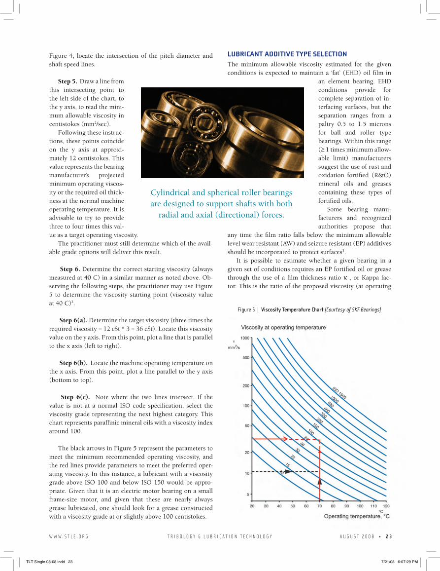
Figure 4, locate the intersection of the pitch diameter and shaft speed lines.
Step 5. draw a line from this intersecting point to the left side of the chart, to the y axis, to read the mini-mum allowable viscosity in centistokes (mm2/sec).
Following these instruc-tions, these points coincide on the y axis at approxi-mately 12 centistokes. This value represents the bearing manufacturer’s projected minimum operating viscos-ity or the required oil thick-ness at the normal machine operating temperature. It is advisable to try to provide three to four times this val-ue as a target operating viscosity.
The practitioner must still determine which of the avail-able grade options will deliver this result.
Step 6. determine the correct starting viscosity (always measured at 40 C) in a similar manner as noted above. Ob-serving the following steps, the practitioner may use Figure 5 to determine the viscosity starting point (viscosity value at 40 C)2.
Step 6(a). determine the target viscosity (three times the required viscosity = 12 cst * 3 = 36 cst). Locate this viscosity value on the y axis. From this point, plot a line that is parallel to the x axis (left to right).
Step 6(b). Locate the machine operating temperature on the x axis. From this point, plot a line parallel to the y axis (bottom to top).
Step 6(c). note where the two lines intersect. If the value is not at a normal IsO code specification, select the viscosity grade representing the next highest category. This chart represents paraffinic mineral oils with a viscosity index around 100.
The black arrows in Figure 5 represent the parameters to meet the minimum recommended operating viscosity, and the red lines provide parameters to meet the preferred oper-ating viscosity. In this instance, a lubricant with a viscosity grade above IsO 100 and below IsO 150 would be appro-priate. Given that it is an electric motor bearing on a small frame-size motor, and given that these are nearly always grease lubricated, one should look for a grease constructed with a viscosity grade at or slightly above 100 centistokes.
LubRICANT ADDITIVE TYPE SELECTIoNThe minimum allowable viscosity estimated for the given conditions is expected to maintain a ‘fat’ (eHd) oil film in
an element bearing. eHd conditions provide for complete separation of in-terfacing surfaces, but the separation ranges from a paltry 0.5 to 1.5 microns for ball and roller type bearings. Within this range (≥ 1 times minimum allow-able limit) manufacturers suggest the use of rust and oxidation fortified (R&o) mineral oils and greases containing these types of fortified oils.
some bearing manu-facturers and recognized authorities propose that
any time the film ratio falls below the minimum allowable level wear resistant (AW) and seizure resistant (eP) additives should be incorporated to protect surfaces3.
It is possible to estimate whether a given bearing in a given set of conditions requires an eP fortified oil or grease through the use of a film thickness ratio κ , or Kappa fac-tor. This is the ratio of the proposed viscosity (at operating
W W W . S T L E . O R G T R I B O L O G Y & L U B R I C A T I O N T E C H N O L O G Y A U G U S T 2 0 0 8 • 2 3
Cylindrical and spherical roller bearings are designed to support shafts with both
radial and axial (directional) forces.
Figure 5 | Viscosity Temperature Chart (Courtesy of SKF Bearings)
TLT Single 08-08.indd 23 7/21/08 6:07:29 PM
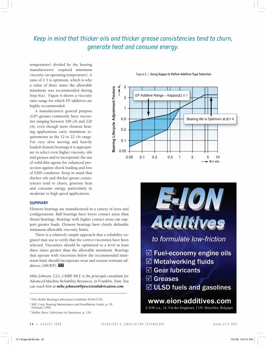
temperature) divided by the bearing manufacturers’ required minimum viscosity (at operating temperature). A ratio of ≥ 3 is optimum, which is why a value of three times the allowable minimum was recommended during step 6(a). Figure 6 shows a viscosity ratio range for which eP additives are highly recommended.
A manufacturer’s general purpose (GP) greases commonly have viscosi-ties ranging between 100 cst and 220 cst, even though most element bear-ing applications carry minimum re-quirements in the 12 to 22 cst range. For very slow moving and heavily loaded element bearings it is appropri-ate to select even higher viscosity oils and greases and to incorporate the use of solid-film agents for enhanced pro-tection against shock loading and loss of eHd condition. Keep in mind that thicker oils and thicker grease consis-tencies tend to churn, generate heat and consume energy, particularly in moderate to high speed applications.
SuMMARYelement bearings are manufactured in a variety of sizes and configurations. Ball bearings have lower contact areas than thrust bearings. Bearings with higher contact areas can sup-port greater loads. element bearings have clearly definable minimum allowable viscosity limits.
There is a relatively simple approach that a reliability en-gineer may use to verify that the correct viscosities have been selected. Viscosities should be optimized to a level at least three times greater than the allowable minimum. Bearings that operate with viscosities below the recommended mini-mum limit should incorporate wear and seizure resistant ad-ditives (AW/eP).
Mike Johnson, CLS, CMRP, MLT, is the principal consultant for Advanced Machine Reliability Resources, in Franklin, Tenn. You can reach him at [email protected].
1 FaG Roller Bearing Lubrication Guideline WL81115E.2 sKF Corp. Bearing Maintenance and Installation Guide, p. 29.
February 1992. 3 Moller, Boor. Lubricants in Operation, p. 116.
2 4 • A U G U S T 2 0 0 8 T R I B O L O G Y & L U B R I C A T I O N T E C H N O L O G Y W W W . S T L E . O R G
Keep in mind that thicker oils and thicker grease consistencies tend to churn, generate heat and consume energy.
Figure 6 | Using Kappa to Refine Additive Type Selection
TLT Single 08-08.indd 24 7/21/08 6:07:31 PM