
Selected Solar-to-heat/Solar-to-electricity · PDF fileD4.8 Selected...
54
SOL2HY2 - Solar To Hydrogen Hybrid Cycles Contract n. 325320 D4.8 Selected Solar-to-heat/Solar-to-electricity concept SOL2HY2_ D4.8.doc Page. 1 SEVEN FRAMEWORK PROGRAMME FCH-JU-2012-1 SP1-JTI-FCH.2012.2.5 : Thermo-electrical-chemical processes with solar heat sources Contract for: Collaborative project D4.8 Selected Solar-to-heat/Solar-to-electricity concept Project acronym: SOL2HY2 Project full title: Solar To Hydrogen Hybrid Cycles Contract no.: 325320 Date of issue: 11 th July 2014 Revision: 1 Category: PU Start date of contract: June 1 st , 2013 Duration of the project: 36 months Project coordinator name: Stefano Odorizzi Project coordinator organisation name: ENGINSOFT S.p.A.
Transcript of Selected Solar-to-heat/Solar-to-electricity · PDF fileD4.8 Selected...

SOL2HY2 - Solar To Hydrogen Hybrid Cycles
Contract n. 325320
D4.8 Selected Solar-to-heat/Solar-to-electricity concept
SOL2HY2_ D4.8.doc Page. 1
SEVEN FRAMEWORK PROGRAMME
FCH-JU-2012-1
SP1-JTI-FCH.2012.2.5 :
Thermo-electrical-chemical processes with solar heat sources
Contract for:
Collaborative project
D4.8 Selected Solar-to-heat/Solar-to-electricity concept
Project acronym: SOL2HY2
Project full title: Solar To Hydrogen Hybrid Cycles
Contract no.: 325320
Date of issue: 11
th July 2014
Revision: 1
Category: PU
Start date of contract: June 1st, 2013
Duration of the project: 36 months
Project coordinator name: Stefano Odorizzi
Project coordinator organisation name: ENGINSOFT S.p.A.

SOL2HY2 - Solar To Hydrogen Hybrid Cycles
Contract n. 325320
D4.8 Selected Solar-to-heat/Solar-to-electricity concept
SOL2HY2_ D4.8.doc Page. 2
D 4.8 Selected Solar-to-heat/Solar-to-electricity concept
Table of Contents:
1. Introduction Page 3
2. Deliverable main contents Page 5
3 Conclusions
4 Acronyms
5 References
Page 49
Page 50
Page 51

SOL2HY2 - Solar To Hydrogen Hybrid Cycles
Contract n. 325320
D4.8 Selected Solar-to-heat/Solar-to-electricity concept
SOL2HY2_ D4.8.doc Page. 3
1. Introduction
1.1. Generalities
The present report deals with the theoretical work carried out in the field of thermal storage of the
CSP and its coupling with the plant to produce hydrogen, according to SOL2HY2 project.
ENEA, DLR, AALTO, Erbicol and EnginSoft have collaborated to realize this report.
In particular DLR focused its attention on the High Temperature heat production and storage
providing its experience on Solar Tower applications.
ENEA applied its experience on the molten salts (NaNO3-KNO3 mixtures) utilization as thermal
storage mean and thermal fluid to find the best solutions to couple the Hydrogen production plant with
the Medium Temperature Solar source and analysing different solutions.
AALTO focused its attention on the Phase Change Materials (PCM) as alternative solution for the
heat storage.
ERBICOL supplied some solutions concerning materials and structures for HT heat storage.
ENGINSOFT introduced the MCDM options to be considered to suggest the most promising
integration schemes for coupling the solar plants (including thermal storage) with the Hydrogen
production plant.
1.2. Objectives
The WP4 is focused on the design of the interface between the power source (CSP plants) and the
thermo-chemical plant. This involves the identification/selection/design/scale up of the most suitable
components for the high- (~800-1000°C) and medium- (300-550°C) temperature applications,
including: solar collectors, solar receiver, heat transfer fluid, heat storage system, heat exchangers and
interfaces with the chemical sections developed in other WPs and possible solar/thermo-electrical
systems.
In particular the task 4.1 is focused on the optimization of the coupling of the thermo-electrochemical
plant with the power source, i.e. the Concentrated Solar Power (CSP) plant. The results of the first
analysis incorporate the specifications of the potential selected layouts for the solar/thermo-
electrochemical plant matching.
In fact, the results of this task will contribute to the realization of the virtual plant and to realize the
necessary hardware to provide a suitable coupling between the CSP and the hydrogen production
plant.
Concerning the realization of the real plant, only some critical equipments will be realized at
demonstrative scale and in this case the thermal storage and the heat transfer equipments are already
available but need integration with direct current (DC) and, heat balance and new material solutions,
mainly for the HT aspects.
Nevertheless for the virtual plant, it is necessary to integrate all the involved parts: H2SO4
concentration, H2SO4 vaporization, SDE, H2SO4 cracking and so on. Some of these must work in
continuous and other not, but need high temperature or electricity.

SOL2HY2 - Solar To Hydrogen Hybrid Cycles
Contract n. 325320
D4.8 Selected Solar-to-heat/Solar-to-electricity concept
SOL2HY2_ D4.8.doc Page. 4
In this field the correct integration between HT and MT plant, the optimized use of energy and storage
is essential and this deliverable contributes to give a panorama of possible solutions, analyses some
critical aspects and contributes to give a first solution to the realization of the whole virtual plant and
to design and run some field tests of key blocks, especially for the production of thermal and electrical
energy.
The results and the solutions individuated in this work package will be also important to the Techno-
economic analysis of the WP6 (T6.3).
With this aim the possibility to assess the mirror surface or thermal storage for different sites or the
implications to vary the percentage of energy provided by MT solar plant on the total is analysed.
Concerning the MT CSP plant, the solution using parabolic solar trough with molten salts as thermal
vector and thermal storage is mostly analysed, because at present guarantees a maximum operating
temperature of 550 °C, modularity, high efficiency of heat to electricity transformation, no toxicity, no
environmental problems, availability of the technology and good integration in the SOL2HY2 system;
nevertheless the use of alternative solutions including PCM systems, mixtures with inclusions,
particular kinds of storage systems are analysed.
The present report initially presents a State of Art on CSPs, in particular Solar Tower and Solar
Trough and makes available the DLR experience on the Julich facilities and the ENEA one for the
Solar Trough.
Successively it describes the principal aspects which affect the solar collection efficiency, in order to
optimize the system, taking into consideration the irradiance available in the analysed sites.
It describes the heat storage concepts concerning the utilization of molten salts in two tanks (the hot
and the cold one), in one tank (exploiting the difference in density with temperature) and in form of
PCM (Phase Change Material with the addition of inclusions as TIO2) and the heat storage concepts
suitable for high temperature storage and suitable for the Solar Tower technology.
Some descriptions on the cycle and the equipments to be used for the electrical energy production and
the related efficiency are also provided.
Finally some important concepts on the material and structures for the heat temperature storage and
the options to be considered to suggest the most promising integration schemes for coupling the solar
with the hydrogen production plant are provided.

SOL2HY2 - Solar To Hydrogen Hybrid Cycles
Contract n. 325320
D4.8 Selected Solar-to-heat/Solar-to-electricity concept
SOL2HY2_ D4.8.doc Page. 5
2. Deliverable main contents
2.1 CSP introduction
Concentrated solar power has been under investigation for several decades. In the CSP, direct solar
radiation is concentrated to heat a so-called heat transfer fluid, which runs an engine connected to a
generator, producing thus electricity. This heat can also be transferred to a receiver-reactor and be
used for thermo-chemical reactions.
CSP is a variable energy source, like solar photovoltaics and wind, but contrary to these last ones, it
can easily be coupled with thermal energy storage (TES) making it dispatchable. Recently, a lot of
improvements and efforts have been done in order to make CSP more cost effective. Ongoing research
works are in the areas of reflector and collector design and materials, heat absorption as well as
thermal storage [R 1].
CSP plants use mirrors to concentrate the sun rays and produce heat and steam for electricity
generation via a conventional thermodynamic cycle.
Unlike solar photo‐voltaic, CSP uses only the direct component of sunlight, namely the direct normal
irradiance (DNI) and provides carbon‐free, cost‐effective heat and power only in regions and countries
with sufficient level of DNI (DNI>2000 kWh/m2‐yr). DNI represents up to 90% of the total sunlight
during sunny days but is negligible on cloudy days
Countries with high DNI level typically include sunny and dry regions between 15°and 40° latitude
North or South of the Equator. Equatorial regions are not particularly suited to CSP because of
frequent clouds and rain. In contrast, high DNI can also be available at high altitude above the sea
level where the light scattering is lower. In most favorable regions the DNI can be as higher as 2800
kWh/m2‐y.
In these regions, the CSP electricity generation potential can reach 100‐130 GWhe/km2/y. This is the
same electricity amount generated annually by a 20 MW coal‐fired power plant, with a 75% capacity
factor.
Best world's regions for CSP installation include the Middle East and North Africa (MENA), South
Africa, Southwestern United States, Mexico, Chile, Peru, Australia, India, Western China, Southern
Europe and Turkey.
However, latitude and altitude alone are not sufficient to characterize a site for CSP installation. Other
key factors include general and local meteorological conditions (e.g. raining, fog, velocity of
dominant winds, general meteorological stability), and site flatness to facilitate the installation of CSP
components, which require significant land use in comparison with conventional power technologies.
CSP plants can be equipped with a heat storage system to generate electricity even when the sky is
cloudy or after sunset. During sunny hours, solar heat can be stored in high thermal‐capacity media
(e.g. fluids). It is then released upon demand (e.g. after sunset) to produce electricity. Thermal storage
can significantly improve the economic competitiveness and the grid integration of CSP plants
because it increases the plant capacity factor, reduces the electricity cost, and improve the
dispatchability of the CSP electricity, namely the ability of the plant to provide electricity on the
operator’s demand.

SOL2HY2 - Solar To Hydrogen Hybrid Cycles
Contract n. 325320
D4.8 Selected Solar-to-heat/Solar-to-electricity concept
SOL2HY2_ D4.8.doc Page. 6
Plant Capacity Factor is usually given as a percentage (%) of operating hours in a year. Conventional
base‐load power plants, in fact, are usually operated at full (nominal) power. Therefore, the capacity
factor is usually defined as the number of hours per year the plant produces electricity at full
(nominal) power. In the solar plants, the power level and the electricity production depend on solar
irradiance. Therefore, the capacity factor is often referred to as the ratio of the actual electricity
generation in a year to the electricity that the plant could in theory produce annually by operating
continuously at full (nominal) power.
To provide the required heat storage capacity, the solar field (i.e. solar heat collectors) of the CSP
plant must be appropriately oversized with respect to the nominal electric capacity (MW) of the power
plant. For this purpose, solar multiple (SM) is the ratio of the actual size of the solar field to the solar
field size needed to feed the turbine at nominal design capacity with maximum solar irradiance. To
cope with thermal losses, plants with no storage have a solar multiple between 1.1‐1.5 and up to 2.0
for the Linear Fresnel Reflectors (LFR) while plants with thermal storage may have solar multiples up
to 3‐4.
There is a trade‐off between the incremental cost associated with the thermal storage and the
economic benefit from increased electricity production. Significant research efforts focus on thermal
storage for CSP plants because this is one of most cost‐effective options for large‐scale energy (and
electricity) storage.
While CSP plants produce primarily electricity, they can also produce high‐temperature heat which
can be used for industrial processes, space heating (and cooling), and other processes such as water
desalination.
The first commercial CSP plants (with no thermal storage) were built in California between 1984 and
1991, with a total capacity of 354 MW distributed in nine units (i.e. SEGS project). After a period of
stagnation due to the low price of fossil fuels, the interest in CSP resumed in the 2000s, mainly in the
United States and Spain, as a consequence of energy policies to mitigate CO2 emissions and diversify
the energy supply.
At present, Spain and the United States are leading countries for CSP development and deployment,
while Germany and Italy contribute significantly into the CSP development. Other countries (e.g.
Saudi Arabia) have announced ambitious CSP deployment plans.
CSP plants are now in operation, under construction or planned in a number of countries. In 2012 the
global installed CSP capacity amounted to about 2 GW up from 1.3 GW in 2010, and an additional
15‐20 GW are currently under construction or planned all over the world.
The available operational experience suggests that a CSP plant can be built in 1‐3 years (depending on
its size), can be operated for more than 30 years and returns the energy used for its construction in
about six months of full‐power operation. The gross CSP land‐use is estimated at approximately 2 ha
per MWe.
Although CSP is not yet economically competitive with conventional coal and gas‐based power, the
CSP industry has been growing rapidly over the past decade. In comparison with other renewable
power sources (e.g. PV and wind power) the competitiveness of CSP plants should be assessed taking
into account two key elements: the important role of the energy storage and the significant potential
SOL2HY2 - Solar To Hydrogen Hybrid Cycles
Contract n. 325320
D4.8 Selected Solar-to-heat/Solar-to-electricity concept
SOL2HY2_ D4.8.doc Page. 7
for reduction of the CSP investment cost due to technology and industrial learning. CSP technology
includes four variants: Solar Tower (ST), Parabolic Trough (PT), Fresnel Reflector (FR), and Solar
Dish (SD).
2.1.1 State of the art of solar tower technology
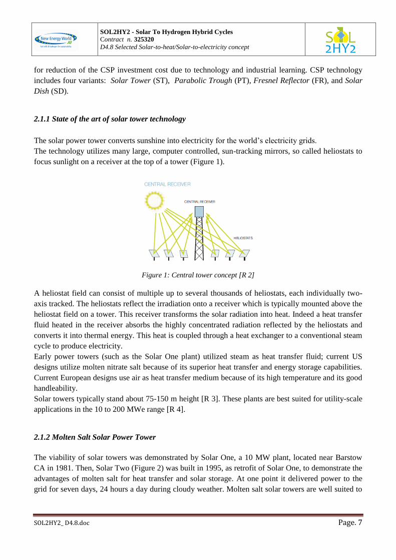
The solar power tower converts sunshine into electricity for the world’s electricity grids.
The technology utilizes many large, computer controlled, sun-tracking mirrors, so called heliostats to
focus sunlight on a receiver at the top of a tower (Figure 1).
Figure 1: Central tower concept [R 2]
A heliostat field can consist of multiple up to several thousands of heliostats, each individually two-
axis tracked. The heliostats reflect the irradiation onto a receiver which is typically mounted above the
heliostat field on a tower. This receiver transforms the solar radiation into heat. Indeed a heat transfer
fluid heated in the receiver absorbs the highly concentrated radiation reflected by the heliostats and
converts it into thermal energy. This heat is coupled through a heat exchanger to a conventional steam
cycle to produce electricity.
Early power towers (such as the Solar One plant) utilized steam as heat transfer fluid; current US
designs utilize molten nitrate salt because of its superior heat transfer and energy storage capabilities.
Current European designs use air as heat transfer medium because of its high temperature and its good
handleability.
Solar towers typically stand about 75-150 m height [R 3]. These plants are best suited for utility-scale
applications in the 10 to 200 MWe range [R 4].
2.1.2 Molten Salt Solar Power Tower
The viability of solar towers was demonstrated by Solar One, a 10 MW plant, located near Barstow
CA in 1981. Then, Solar Two (Figure 2) was built in 1995, as retrofit of Solar One, to demonstrate the
advantages of molten salt for heat transfer and solar storage. At one point it delivered power to the
grid for seven days, 24 hours a day during cloudy weather. Molten salt solar towers are well suited to

SOL2HY2 - Solar To Hydrogen Hybrid Cycles
Contract n. 325320
D4.8 Selected Solar-to-heat/Solar-to-electricity concept
SOL2HY2_ D4.8.doc Page. 8
peaking power applications, being able to generate power when most needed, day or night, cloudy or
sunny. In a molten-salt power tower, the molten nitrate salt, which is a clear liquid with properties like
water at temperatures above its 240°C melting point, is pumped from a large storage tank to the
receiver, where it is heated in tubes to temperatures of 565°C [R 5]. The salt is then returned to a
second large storage tank, where it remains until needed by the utility for power generation. At that
time, the salt is pumped through a steam generator to produce the steam to power a conventional,
high-efficiency steam turbine to produce electricity. The salt at 285°C then returns to the first storage
tank to be used in the cycle again.
Figure 3 is a schematic diagram of the primary flow paths in a molten-salt power plant.
Figure 2: Solar Two, Barstow, CA
Figure 3: Molten salt power tower system schematic
The 17 MWel Gemasolar plant (see Figure 4) developed by Torresol Energy and connected to the grid
in 2011 uses also molten salt as heat transfer fluid and for thermal storage. This plant is designed to
operate round-the-clock in summertime [R 6].
Figure 4: Gemasolar plant of torresol Energy in Andalucia, Spain

SOL2HY2 - Solar To Hydrogen Hybrid Cycles
Contract n. 325320
D4.8 Selected Solar-to-heat/Solar-to-electricity concept
SOL2HY2_ D4.8.doc Page. 9
2.1.3 Air solar power tower
The 1.5 MWe solar thermal experimental and demonstration power plant in Jülich, Germany (Figure
5) was declared operational in December 2008. It is the world’s first solar thermal power plant erected
which uses air as the medium for heat transport. Air was chosen as the heat transfer medium, since it
is freely available, non-toxic, and does not require freeze protection during times of non-operation.
Over 2,000 movable mirrors concentrate the solar radiation onto the receiver at the top of the 60-metre
tower. The receiver is a volumetric receiver consisting in porous ceramic structure on which the solar
radiation is focused and through which incoming ambient air flows. This receiver was developed and
patented by DLR. The volumetric effect increases the efficiency. The air cools the outer parts of the
receiver and is heated up gradually to the design temperature level at the inner surface. In passing
through the receiver, the air is heated to around 700°C and this heat is delivered to the water-steam
cycle in a heat recovery boiler. Steam parameters may be up to 100 bar and 500°C, which is in the
typical range for medium-sized conventional power plants. The steam generated there drives a
turbine/generator and returns in form of condensate to the steam generator (Figure 5). The receiver
can be a tube receiver or a volumetric receiver, consisting of porous ceramic structures, e.g.
honeycombs or foams, which are heated by the concentrated solar radiation. In such a case air is
sucked through the ceramic structures and hence heated.
Figure 5: Jülich Solar tower plant (left) and plant layout (right) [R 7]
2.2. Solar Trough Technology and ENEA experience
As already mentioned, CSP technology includes four variants: Parabolic Trough (PT), Fresnel
Reflector (FR), Solar Tower (ST) and Solar Dish (SD). In PT and FR plants, mirrors concentrate the
sun’s rays on a focal line, with concentration factors of 60‐80 and maximum operating temperatures of
about 550°C. In ST and SD plants, mirrors concentrate the sunlight on a single focal point, with
higher operating temperatures and concentration factors (up to 10‐fold higher).

SOL2HY2 - Solar To Hydrogen Hybrid Cycles
Contract n. 325320
D4.8 Selected Solar-to-heat/Solar-to-electricity concept
SOL2HY2_ D4.8.doc Page. 10
At present, Parabolic Trough is the most mature and cost effective CSP technology accounting for
more than 90% of the current installed CSP capacity.
It is based on linear parabolic mirrors that concentrate the sun’s rays on heat receivers (i.e. steel tubes)
placed on their focal line.
Receivers have a special coating to maximize the energy absorption and minimize the infrared
re‐irradiation. The receiver tubes are placed inside an evacuated glass envelope to avoid convection
heat losses.
Solar heat is removed by a heat transfer fluid (e.g. synthetic oil, molten salt) flowing in the receiver
tube. It is then transferred to a steam generator to produce super‐heated steam and run the turbine.
Mirrors and receivers (i.e. the solar collectors) track the sun along a single axis (usually, East to
West).
Most PT plants that are currently in operation have capacities between 15 and 100 MWe, efficiencies
of around 14‐16% (i.e. the ratio of net electric output to solar energy input) and a maximum operating
temperature of 390°C, which is limited by the degradation of the synthetic oil that is used as the heat
transfer fluid. Some of these plants have a thermal storage system based on the use of molten salt as a
storage fluid, which storage temperature is also limited by the oil maximum temperature.
Apart from the SEGS project, recent major PT projects in operation include two 70‐MW units in the
United States (i.e. Nevada Solar One and MNGSEC‐Florida), a number of 50‐MW units in Spain and
smaller units in a number of countries. As mentioned, some 50‐MW power plants in Spain use
synthetic oil as the heat transfer fluid and molten salt as the thermal storage fluid, with a thermal
storage capacity of around 7.5 hours and a capacity factor of up to 40%.
As of January 2013, large PT plants under construction include the Mojave project (250 MW,
California, 2013), the Solana project (280 MW, Arizona, 2013), the Shams 1 project (100 MW,
United Arab Emirates, 2012), the Godawari project (50 MW, India, 2013) and further 50‐MW plants
in Spain.
CSP plants are designed for electricity generation, but they can also produce high‐temperature heat
that can be used for industrial heating, water desalination, production of synthetic fuels (e.g syngas),
oil refinery, and enhanced oil recovery (EOR) in mature oil fields.
The use of CSP plants for production of electricity and heat, and water desalination is of particular
interest in arid regions where CSP can provide either electricity for desalination by reverse‐osmosis or
heat for desalination by thermal distillation. CSP can also be integrated into hybrid CSP/fossil fuel
plants in order to produce fully dispatchable electricity.
In this case, the solar field provides steam to the thermodynamic cycle of the conventional power
plant.
Projects based on this concept are in operation in Algeria, Australia, Egypt, Italy and the United
States.
In the period 2001‐2010 ENEA has developed a novel concept of CSP PT plant using
high‐temperature (550°C) molten salt either for heat transfer and heat storage purposes. The use of
high‐temperature molten salt not only increases the efficiency of the plant but also increases
significantly the capacity of the thermal storage system and/or reduces its costs.

SOL2HY2 - Solar To Hydrogen Hybrid Cycles
Contract n. 325320
D4.8 Selected Solar-to-heat/Solar-to-electricity concept
SOL2HY2_ D4.8.doc Page. 11
However, the use of high‐temperature molten salt requires new technologies for key components of
the CSP plant such as solar collectors, heat receivers, and the heat storage system. These new
components and systems have been developed and patented by ENEA, and tested at the full‐scale CSP
test facility (Figure 6) that was built since 2004 at the ENEA Casaccia Labs in Rome and has been
working now for more than 20,000 hours. Of particular importance are the high‐temperature
heat‐receiver tubes working under vacuum at 550°C, with a special coating to maximise heat
absorption and minimise losses. Italian companies have been involved in the R&D programme and
currently produce the receiver tubes and other components under ENEA license.
A 5‐MWe demonstration plant (Archimede Solar Plant) with about 6.5 h thermal storage was built by
ENEL, the largest Italian utility, in Sicily (Italy) based on ENEA patents. The plant started the
operation in July 2010 and was the first one in the world using molten salt as either heat transfer and
storage fluid. The novel technology is expected to improve significantly the storage performance and
the capacity factor of CSP plants up to more than 60%.
The Archimede power plant is intended to test components and systems of the new technology under
real operating conditions. The solar plant is part of a 760 MW gas‐fired combined cycle power station
and uses the same steam turbine of the conventional power block. This arrangement allows the
demonstration to focus only on innovative components, i.e. solar field, solar collectors, heat receivers,
storage system, molten salt operation and piping.
The hot tank provides heat to the steam generator to produce superheated steam at 535°C. ENEL is in
charge of the plant demonstration programme.
The use of high‐capacity storage systems improves the flexibility of CSP plants, which can provide
either dispatchable electricity and high‐temperature heat for industrial or residential use. Moreover,
molten salt (a 60‐40% mix of KNO3‐NaNO3) is safer (non‐flammable), cheaper and more
environmentally friendly in comparison with synthetic oil.
ENEA is currently involved in further optimization of the CSP technology, including alternative heat
transfer/storage fluids, streamlined heat storage systems, improved heat receivers, as well as CSP
applications based on the use of high‐temperature solar heat (e.g. production of synthetic fuels via
reforming and thermo‐chemical processes, water desalination via thermal process or reverse osmosis).

SOL2HY2 - Solar To Hydrogen Hybrid Cycles
Contract n. 325320
D4.8 Selected Solar-to-heat/Solar-to-electricity concept
SOL2HY2_ D4.8.doc Page. 12
Figure 6: Solar collector s' tests at the ENEA Casaccia Labs (Rome)
2.3 Efficiency evaluation
2.3.1 Efficiency evaluation of solar tower technology
Optical efficiency of heliostat field
The solar collector field of central receiver systems is of particular importance as it accounts for the
largest cost fraction of a solar power plant. Several loss mechanisms affect the optical efficiency of
the heliostat field. Most importantly is the cosine effect annually varying between 0.9 and 0.7 [R 4]
which arises from the angle between incoming radiation from the sun and reflected radiation to the
solar receiver. Other losses are attributed to shading (mirror surface shadowed by other heliostats),
reflectivity of the mirror, blocking (reflected radiation hitting other heliostats), atmospheric
attenuation (radiation absorbed by the atmosphere between heliostat and receiver), spillage (reflected
radiation missing the receiver) and, if applicable, transmission losses of secondary optics.
Depending on the geographic latitude and the use of secondary concentrators a surround field or a
north/south field can be favourable. Generally, surround field have advantages close to the equator,
while north (on the northern hemisphere) or south (on the southern hemisphere) fields become

SOL2HY2 - Solar To Hydrogen Hybrid Cycles
Contract n. 325320
D4.8 Selected Solar-to-heat/Solar-to-electricity concept
SOL2HY2_ D4.8.doc Page. 13
beneficial at higher latitudes. A study of Schmitz et al. [R 8] found that surrounding fields can also
become favourable for large fields if secondary optics are required.
Secondary concentrators are necessary for the clustering of cavity receivers, especially, if windows
are required which is the case for the receiver-reactor for sulphuric acid cracking developed in the
SOL2HY2 project. Particularly for large power plants high towers are required which, however,
increase optical losses due to atmospheric attenuation and spillage. Schmitz et al. [R 8] find that
systems with a single aperture using a north field have optimal tower heights which are about 30 %
higher than for multi aperture receivers using a surround field.
Typical optical efficiencies are reported by Kolb et al. [R 9]: a particle receiver for sulphuric acid
cracking in a hybrid sulphur cycle hydrogen plant is found to have an annual optical efficiency of
57 % resulting from a cosine efficiency of 85 %, a shading and blocking efficiency of 96 %, an
atmospheric attenuation efficiency of 88 % and an intercept efficiency of 90 %.
Thermal efficiency of receivers
The thermal efficiency of solar receivers is mainly determined by the fraction of radiative losses
which can never be fully avoided due to the required opening towards the solar collector field.
Generally, receivers for solar towers can be categorized into those with a cavity design and others
with an external design. In the first concept the area of the aperture is smaller than the absorbing
surface reducing radiative losses while in the latter case aperture and absorber have the same surface
limiting the achievable thermal efficiency. Solar receivers can either be directly irradiated using
volumetric absorbers being porous or consisting of particles with the heat transfer fluid flowing
through the open volume; or the receiver is indirectly irradiated so that the heat has to be conducted
through the wall of a tubular absorber before transferring it to the working fluid. Generally, higher
temperatures and thermal efficiencies are achievable with volumetric designs; however, pressuring
these systems requires the use of windows limiting the operating pressure.
Typical temperature and solar flux ranges of receivers for solar towers are given in Table 1.
Fluid Water steam Liquid sodium Molten salt
(nitrates)
Air
(volumetric)
Solar flux (MW/m2)
Average 0.1-0.3 0.4-0.5 0.4-0.5 0.5-0.6
Peak 0.4-0.6 1.4-2.5 0.7-0.8 0.8-1.0
Fluid outlet
temperature (°C) 490-525 540 540-565 700 to >1000
Table 1: Temperature and solar flux ranges of solar receivers for solar towers [R 4]
Thermal efficiencies of more than 80 % are possible with solar tower receivers. In a screening
analysis of various concepts for thermochemical hydrogen production Kolb et al. [R 9] report an

SOL2HY2 - Solar To Hydrogen Hybrid Cycles
Contract n. 325320
D4.8 Selected Solar-to-heat/Solar-to-electricity concept
SOL2HY2_ D4.8.doc Page. 14
annual thermal efficiency of 76 % for a solid particle receiver to decompose sulphuric acid in a hybrid
sulphur cycle hydrogen plant.
2.3.2 Solar Trough efficiency
Concerning solar trough efficiency due to plant geometry and design, it includes the optical efficiency
of the overall collector structure and the thermal efficiency of the receiver tube. The optical efficiency
of the solar collectors depends on the mechanical design (collector's geometry, interception factor),
quality of materials (reflectance of the mirrors,) and the accuracy of alignment. Thermal efficiency of
the receiver tube instead depends on the absorbance of the selective coating (emissivity as a function
of temperature), transmittance of tube glass, and intensity of the solar radiation.
However, an important factor is mirror and glass tube fouling during operation. Reflectivity declines
by some 14 percentage points in a month, corresponding to a 0.5% per day reduction.
Degradation rate depends on the site. In any case, periodical washing is needed to restore the design
reflectivity. A trade‐off exist between washing costs (frequency) and efficiency reduction. Weekly
cleaning determines a reflectivity mean value of about 90%. In the absence of fouling site‐relevant
data, an average reduction of the absorbed energy of about 5.5% could be considered, based on 26
cleaning cycle per year, with a water consumption of 0.7 L/m2.
Thermal energy collected by the solar field and efficiency of the heat capture is the key to assess the
annual electricity production and the overall efficiency of the CSP plant. This efficiency, also referred
to as optical efficiency, depends on the optical performance of solar collectors and the thermal
performance of the receiver tubes. Key parameters for solar collectors and receiver tubes, which
determine the optical efficiency are given in Table 2 where the fouling factor is derived from
available operating experience with CSP plants. Based on Table 2, the optical efficiency is 0.756
including the fouling effect. This means that 75.6% of the solar thermal power available at collector's
surface is absorbed by the receiver tube. The actual thermal power that is absorbed by the heat transfer
fluid depends on the thermal efficiency of the receiver tube, which in turn depends on the selective
coating of the tube, its emittance, the operating temperature, and the intensity of the solar irradiance.
As solar collectors are grouped into strings including 6-8 SCA (Solar Collector Assembly) with
in‐series connection, thermal efficiency and optical efficiency refer to the string and are also a
function of the intensity of the solar irradiance.
If the solar irradiance is suitable, thermal fluid in the tubes can flow at a speed such that the turbulence
to have a good thermal exchange, assures at the same time the requested salt warming (from 290 to
550 °C) and an high solar energy absorption by salts. In this case the efficiency will be the highest
possible.
On the contrary, if the solar irradiance decreases, in order to assure the same salt warming gradient (it
is a constraints for the users), it is necessary reduce the salt flow, in fact the absorbed energy depends
on flow, heat capacity and temperature gradient (Q ~ W*cp*DT ). Nevertheless, in this last case, the
turbulence and consequently the heat exchange lower.

SOL2HY2 - Solar To Hydrogen Hybrid Cycles
Contract n. 325320
D4.8 Selected Solar-to-heat/Solar-to-electricity concept
SOL2HY2_ D4.8.doc Page. 15
Obviously, it is not possible to reduce the salt flow endlessly, because flow would become laminar
and heat exchange too low, with salt solidification risks too. The red line in Figure 7 represents the
trend when the flow must be kept to the minimum flow constantly, but in this case it is not possible to
assure the nominal outlet temperature (550 °C) and under a certain exit temperature the heat collected
will be used to compensate the heat losses.
Therefore, the total collector efficiency ranges from 0.4 and 0.69 (see Figure 7). It should be noted that
this analysis includes a molten salt flow rate in the string ranging between 2.5 kg/s and 7.9 kg/s for
solar irradiance between 380 W/m2 and 1000 W/m
2, respectively, in order to obtain a constant outlet
temperature of 550°C. It should also be noted that in the case of no solar irradiance, the minimum
mass flow rate is setup at 2.5 kg/s . In some cases, it is possible to arrive at 2 kg/s in order to collect
solar irradiance up to 320 kW/m2 (Figure 8).
Parametrs Value
Interception Factor 0.986
Sun tracking Factor 0.99
Mirror Reflectance Factor 0.96
Tube Glass Fouling Factor 0.97
Bellows Shading effect on tube receiver 0.96
Mirror Fouling Factor 0.95
Glass Tube Transmittance Factor 0.96
Receiver Tube Absorbance Factor 0.95
Table 2 : Key Parameters for Solar Collector Performance
‐
Figure 7 : Total Collectors' Efficiency of the String example
0
0,1
0,2
0,3
0,4
0,5
0,6
0,7
0,8
0,9
1
0 0,1 0,2 0,3 0,4 0,5 0,6 0,7 0,8 0,9 1
Tota
l Eff
icie
ncy
Irradiance [kW/m2]
M = 2.5 kg/s M > 2.5 kg/s
Poli. (M > 2.5 kg/s)

SOL2HY2 - Solar To Hydrogen Hybrid Cycles
Contract n. 325320
D4.8 Selected Solar-to-heat/Solar-to-electricity concept
SOL2HY2_ D4.8.doc Page. 16
The overall energy balance of the CSP plant includes the solar field, the molten salt distribution
network, the heat storage system, the steam generator, and the thermodynamic cycle.
The energy absorbed by the heat transfer fluid is calculated based on the hourly profile of the effective
solar irradiance (Aperture Normal Irradiance - ANI), the total mirrors surface in the solar field, and
the average efficiency of solar collector strings. The energy absorbed by the fluid minus the network
loss is the energy available for storage.
Figure 8: molten salts flow into the loop.
The energy balance of the storage system takes into account the maximum storage capacity, the
profile of the useful energy to supply to the steam generator in order to produce electricity. If sunlight
is not available (overnight or under cloudy sky), molten salt needs to be re‐circulated through the solar
field and the storage cold tank to keep the required molten salt temperature with a certain safety
margin. This involves (re)circulation loss.
The basic assumption to assess the plant performance is that the power plant works if thermal energy
is available in the storage system, otherwise the steam generator is in the stand‐by condition, with no
electricity production. Actual annual operation of the power plant includes periods with different
power level depending on solar irradiance availability. Based on a nominal thermal power of the
steam generator, the operating window is between 36% (typically, December and January) and 110%
(May to August) of the nominal thermal power. As the efficiency of the power block with low load
level is about 90% of its nominal value, the thermal power that is needed to produce electricity is
about 40% of the nominal thermal power.
The annual energy balance also accounts for the average thermal losses of the solar field including
connection piping (i.e. about 100 W/m) and the thermal losses of main headers and manifolds of the
molten salt distribution network (i.e. about 150 W/m); the weighted average of the total thermal losses
is estimated at about 104 W/m (solar field and network) or 18 W/m2 of reflecting surface.
Given the maximum capacity of the storage system, a part of storable energy can be discharged when
the hot storage tank is full (discharged energy). In this case, some strings of solar collectors can be

SOL2HY2 - Solar To Hydrogen Hybrid Cycles
Contract n. 325320
D4.8 Selected Solar-to-heat/Solar-to-electricity concept
SOL2HY2_ D4.8.doc Page. 17
misaligned from the focal line in order not to capture further thermal power. In contrast, if the hot tank
is empty and sunlight is not available, an energy addition from an external source may be needed to
ensure molten salt circulation (e.g. overnight circulation).
2.4 Thermal storage
A big advantage of the CSP technology is the capability to provide dispatchable power – by storing
solar energy in thermal reservoirs and releasing it as and when it's needed i.e. during periods of peak
power demand, during cloudy weather or even at night. So storage can eliminate intermittency as well
as extend energy production past sun-set.
Solar heat collected during the day can be stored in liquid or solid media such as molten salts,
ceramics, concrete, phase-changing salt mixtures or in saturated water. At night, the heat can be
extracted from the storage medium to keep the turbine running.
2.4.1 High temperature storage
High temperature heat storage with molten salts
Molten salt is in current applications. This heat storage medium retains thermal energy effectively
over time and matches well with the most efficient steam turbines. Moreover molten salt is a non-
toxic, readily-available material. Molten salt can act as both Heat Transfer Fluid and Thermal Energy
Storage, which improves the overall plant efficiency and lowers the cost.
These first systems employed molten salts in an indirect two-tank design (see Figure 9). For example
the Solar Two receiver was comprised of a series of panels (each made of 32 thin-walled, stainless
steel tubes) through which the molten salt flowed in a serpentine path. The salt storage medium was a
mixture of 60 percent sodium nitrate and 40 percent potassium nitrate [R 10].
The thermal storage system was a two-tank system designed to deliver thermal energy at full rated
duty of the steam generator for three hours at the defined hot and cold salt temperatures of 565 °C and
288 °C, respectively. So after the first cycle, the salt from the cold tank is heated from 288 °C to the
hot tank temperature of 565 °C during charging, and the process is reversed during discharging.

SOL2HY2 - Solar To Hydrogen Hybrid Cycles
Contract n. 325320
D4.8 Selected Solar-to-heat/Solar-to-electricity concept
SOL2HY2_ D4.8.doc Page. 18
Figure 9: Two-tank indirect thermal energy storage system
More recently, the Torresol, Gemasolar Power Tower in Seville, Spain uses a molten salts storage
system in a direct two-tank design (see R 10). The storage medium acts also as heat transfer fluid,
removing the need for a heat exchanger and hence redusing cost and increasing overall efficiency [R
11]. The storage capacity is 15 hours for a plant capacity 12 MWe [R 12].
Figure 11 shows molten salts storage tanks of Gemasolar.
Figure 10: Two- tank direct storage system
Figure 11: Gemasolar molten salts storage tank
Determining the optimum storage size to meet power-dispatch requirements is an important part of the
system design process. Storage tanks can be designed with sufficient capacity to power a turbine at
full output for up to 15 hours.
The heliostat field that surrounds the tower is laid out to optimize the annual performance of the plant.
The field and the receiver are also sized depending on the needs of the utility. In a typical installation,
solar energy collection occurs at a rate that exceeds the maximum required to provide steam to the
SOL2HY2 - Solar To Hydrogen Hybrid Cycles
Contract n. 325320
D4.8 Selected Solar-to-heat/Solar-to-electricity concept
SOL2HY2_ D4.8.doc Page. 19
turbine. Consequently, the thermal storage system can be charged at the same time that the plant is
producing power at full capacity. The ratio of the thermal power provided by the collector system (the
heliostat field and receiver) to the peak thermal power required by the turbine generator is, as said, the
solar multiple. With a solar multiple of approximately 2.7, a molten-salt power tower located in the
California Mojave desert can be designed for an annual capacity factor of about 65%. Consequently,
a power tower could potentially operate for 65% of the year without the need for a back-up fuel
source. Without energy storage, solar technologies are limited to annual capacity factors near 25%.
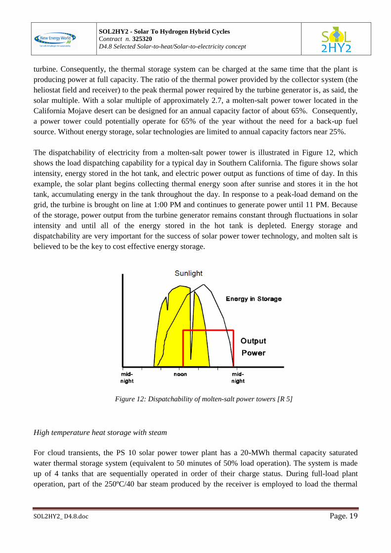
The dispatchability of electricity from a molten-salt power tower is illustrated in Figure 12, which
shows the load dispatching capability for a typical day in Southern California. The figure shows solar
intensity, energy stored in the hot tank, and electric power output as functions of time of day. In this
example, the solar plant begins collecting thermal energy soon after sunrise and stores it in the hot
tank, accumulating energy in the tank throughout the day. In response to a peak-load demand on the
grid, the turbine is brought on line at 1:00 PM and continues to generate power until 11 PM. Because
of the storage, power output from the turbine generator remains constant through fluctuations in solar
intensity and until all of the energy stored in the hot tank is depleted. Energy storage and
dispatchability are very important for the success of solar power tower technology, and molten salt is
believed to be the key to cost effective energy storage.
Figure 12: Dispatchability of molten-salt power towers [R 5]
High temperature heat storage with steam
For cloud transients, the PS 10 solar power tower plant has a 20-MWh thermal capacity saturated
water thermal storage system (equivalent to 50 minutes of 50% load operation). The system is made
up of 4 tanks that are sequentially operated in order of their charge status. During full-load plant
operation, part of the 250ºC/40 bar steam produced by the receiver is employed to load the thermal

SOL2HY2 - Solar To Hydrogen Hybrid Cycles
Contract n. 325320
D4.8 Selected Solar-to-heat/Solar-to-electricity concept
SOL2HY2_ D4.8.doc Page. 20
storage system. When energy is needed to cover a transient period, the energy is recovered from the
saturated water at 20 bar to run the turbine at 50% load.
Figure 13 represents the steam storage plant concept.
Figure 13: Plant concept with steam storage [R 10]
Figure 14 shows the steam storage tanks for the PS10 power tower.
Figure 14: heat storage tanks for the PS10 power tower
PS 10 and PS 20 have each a storage capacity of 60 minutes [R 13].
High temperature heat storage with concrete
In the air-cooled solar tower from Jülich, Germany, a thermal storage is connected parallel to the
boiler. The storage system consists of a rectangular housing of 7 m*7 m*6 m size. The storage is
partitioned into four chambers of identical size, connected in parallel through a dome and connecting
SOL2HY2 - Solar To Hydrogen Hybrid Cycles
Contract n. 325320
D4.8 Selected Solar-to-heat/Solar-to-electricity concept
SOL2HY2_ D4.8.doc Page. 21
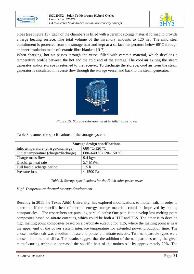
pipes (see Figure 15). Each of the chambers is filled with a ceramic storage material formed to provide
a large heating surface. The total volume of the inventory amounts to 120 m3. The mild steel
containment is protected from the storage heat and kept at a surface temperature below 60°C through
an inner insulation made of ceramic fibre blankets [R 7].
When charging, hot air passes through the vessel filled with ceramic material, which develops a
temperature profile between the hot and the cold end of the storage. The cool air exiting the steam
generator and/or storage is returned to the receiver. To discharge the storage, cool air from the steam
generator is circulated in reverse flow through the storage vessel and back to the steam generator.
Figure 15: Storage subsystem used in Jülich solar tower
Table 3 resumes the specifications of the storage system.
Storage design specifications
Inlet temperature (charge/discharge) 680 °C/120 °C
Outlet temperature (charge/discharge) 680–640 °C/120–150 °C
Charge mass flow 9.4 kg/s
Discharge heat rate 5.7 MWth
Full load discharge period 1.5 h
Pressure loss < 1500 Pa
Table 3: Storage specifications for the Jülich solar power tower
High Temperature thermal storage development
Recently in 2011 the Texas A&M University, has explored modifications to molten salt, in order to
determine if the specific heat of thermal energy storage materials could be improved by adding
nanoparticles. The researchers are pursuing parallel paths: One path is to develop low melting point
composites based on nitrate eutectics, which could be both a HTF and TES. The other is to develop
high melting point composites based on a carbonate eutectic for TES, where the melting point is near
the upper end of the power system interface temperature for extended power production time. The
chosen molten salt was a sodium nitrate and potassium nitrate eutectic. Two nanoparticle types were
chosen, alumina and silica. The results suggest that the addition of the nanoparticles using the given
manufacturing technique increased the specific heat of the molten salt by approximately 20%. The

SOL2HY2 - Solar To Hydrogen Hybrid Cycles
Contract n. 325320
D4.8 Selected Solar-to-heat/Solar-to-electricity concept
SOL2HY2_ D4.8.doc Page. 22
silica and the alumina improved the specific heat by nearly the same amount over the base material [R
14].
A more long-term research programme is underway at the National Renewable Energy Laboratory
(NREL), where researchers are looking to develop a new class of TES materials and increase the heat
capacities by a factor of 5. The researchers at NREL are developing nano-scale ‘encapsulated’
structures of 50 to 500 atoms that can then be suspended in fluids. These nano-clusters have
embedded metals with a ceramic-like outer coating. The research direction is to have clusters which
can provide tuneable parameters to improve the TES functionality and at the same time withstand the
repeated cycling between states. The overall concept is to use a family of nano-particles with different
transition points to smooth out the phase transitions and achieve a simple linear dependence between
energy and temperature. The most success was obtained with noble metals, but those are also the most
expensive materials. They are looking to other less expensive metals too [R 14].
Presently the development of TES materials is very much in an R&D phase, and lagging the collection
hardware development. Although there are very few commercial suppliers, there are now several
strong R&D programmes in place including the USA, Spain, Germany and France.
Table 4 shows a representative layout of the current development activities:
TES
Now Steam accumulator
Molten salts
Near term Phase change
Improved molten salts
Nanoscale molten salts
Solid materials storage
Emerging concepts Thermo-chemical
Nano fluids
Table 4: current TES development activities [R 14]
2.4.2 Medium temperature storage
The realization of thermal storage in CSP type solar trough, in the version adopted by ENEA, foresees
both in the field that in the solar storage system the use of binary salts.
In this way there is "direct" storage. Unlike, systems that use oil as thermal fluid and salt as storage
mean show an indirect storage because an heat exchanger is interposed between the two circuits. Since
the binary mixture of the salts cannot fall below 238 ° C for freezing problems, a minimum
temperature of the cold reservoir equal to 290 ° C is generally set; the temperature of the hot reservoir,
instead, is fixed at 550 ° C, upper working limit of the binary salts. A boiler integration based on fossil
fuels is expected to compensate for the loss of the solar field.

SOL2HY2 - Solar To Hydrogen Hybrid Cycles
Contract n. 325320
D4.8 Selected Solar-to-heat/Solar-to-electricity concept
SOL2HY2_ D4.8.doc Page. 23
Because of the upper limit on the operating temperature of the binary salts, it will be necessary to
control the flow within the solar field as a function of the intensity of the radiation.
Figure 8 shows the trend of the salts mass flow rate in the loop of the solar field; it was limited
inferiorly to a value equal to 2 kg/s in such a way as to reach 550 ° C even in the presence of low solar
radiation equal to about 320 W/m2. The loop is a series of collectors where the warm up of thermal
fluid happens. Generally 6 collectors in series are necessary to reach 550 °C from 290°C. In order to
better manage the flow variations and efficiency, 8 collectors can be used for each loop.
To describe the system working, first hours of the day have low solar radiations, the hot tank is empty
and the cold one is full; so the flow leaving the solar field is equal to the minimum value required by
circuit and it is sent to the cold tank even if it has a temperature above 290 °C.
During the day, solar irradiation increases and consequently also molten salt flow in the solar field;
when the molten salts output temperature is greater than the threshold vale (e.g. 520 °C), the salts are
sent to the hot tank to be stored and/or to produce thermal energy.
Otherwise, if the fluid temperature is inferior than the threshold, the salt is sent back to the cold tank
to store solar energy to be used for the thermal losses compensations.
During the storage loading phase, the level of the hot tank is controlled in such a way that the inlet
flow rate is not greater than the capacity available in the reservoir.
In this way, during the solar irradiation time, the hot tank fills up, a part of collected energy directly
feeds the users while the remaining fraction of the stored heat will be used when there is not enough
solar irradiation. In fact, in this last case, the hot stored fluid is withdrawn and sent to the users,
emptying the hot tank and filling up the cold one.
A possible problem that may arise during the annual operation of the plant is related to the summer
months when there is a very high solar radiation, so it can happen that by recirculating hot salts (Tref
<520 ° C) in the cold tank there is an excessive raising of its temperature with consequent rising in the
temperature of the fluid entering the solar field. In these circumstances the output salts would reach
temperatures above 550 ° C, with harmful consequences for the integrity of the system. To avoid this
dangerous condition it is necessary to put out fire one or more collectors, losing energy.
From the above, it is clear the storage size significantly affects the productivity of the plant, in fact, if
the mass of stored salt is lower than the amount able to absorb the power that may be accumulated
during the day, part of this should be wasted. On the other hand, it is reasonable to arrive at a
compromise between storage costs and lost power.
So it is possible to establish the storage size and make an assessment of the thermal inputs.
From the curve of the daily time solar radiation, using the total collecting surface of the solar field and
the efficiency curve of the string manifolds, it is possible to evaluate the thermal energy absorbed by
the fluid (energy consumption).
This, purified by thermal losses represents the energy that can potentially be stored in the storage
system (energy accumulated).
ENEA has been also studying an alternative way to store thermal energy by molten salts through a
system based on a single tank containing a thermal storage liquid material (HSM: heat storage
material) where energy is stored (during the charging phase) as sensible heat, and, during thermal
SOL2HY2 - Solar To Hydrogen Hybrid Cycles
Contract n. 325320
D4.8 Selected Solar-to-heat/Solar-to-electricity concept
SOL2HY2_ D4.8.doc Page. 24
discharging, the energy is transferred to another fluid by a heat exchanger immersed into the HSM
bulk. The working concept is based on maintaining a vertical thermal stratification profile in the
HSM fluid (thermocline), which is due to the layers difference of density with temperature.
At the ENEA solar energy test facility (PCS), a binary mixture of nitrate salts (60% NaNO3 and 40%
KNO3 in weight percentage) has been tested as HSM at this aim. This mixture, in general known as
“solar salt”, because its large employment in CSP plants, presents a solidus point (that is, the
temperature where the liquids starts forming a solid phase by cooling) of about 240 °C, but, for
practical reason is employed above 290 °C (cold temperature); the upper temperature limit can be
considered at around 600 °C, though, at the ENEA test rig 550°C is the higher (hot) temperature
value.
The experimental work has shown that the thermal stratification of the molten salts mixture can be
maintained quite constant for several hours and the presence of the integrated steam generator actively
guarantees and maintains the stratification during the operation time, avoiding mixing of the stratified
layers. This behaviour is also favoured, in absence of perturbative phenomena, by the low temperature
value of the solar salt thermal conductivity (about 0.5 W/K m). Another characteristic of the nitrate
mixture which enhances the thermocline stability against the homogenization due to convection is
related to the dynamic viscosity trend respect to temperature: this value increases of about 60% from
550°C to 290°C, hindering the mass transfer from the cold layers towards the hotter ones [R 15].
In Figure 16 is shown a scheme of the ENEA test facility, consisting of a 300 kWth SG inserted in a 8
m³ molten salts storage tank. Also the position of the thermocouples, positioned at different heights, is
indicated.

SOL2HY2 - Solar To Hydrogen Hybrid Cycles
Contract n. 325320
D4.8 Selected Solar-to-heat/Solar-to-electricity concept
SOL2HY2_ D4.8.doc Page. 25
Figure 16 : Scheme of the experimental set-up
Medium temperature storage alternatives
Thermal energy can be stored as well as sensible heat, also by means of latent heat fusion (using
PCM, phase change material as storage media) and as thermo-chemical reactions or a combination of
these in order to increase the total amount of stored heat [R 16].
In terms of storage media there are a wide variety of organic and inorganic pure compounds, mixtures,
and eutectic mixtures, depending on the temperature range and application. In literature [R 17-R 20] a
classification of PCM (paraffin waxes, fluorides, chlorides, hydroxides, alkali nitrates, carbonates,
other salts, and metal alloys) is made according to the melting temperature (°C), heat of fusion (kJ/kg)
and the thermo-physical properties such as density (kg/m3), specific heat (kJ/kg K), and thermal
conductivity (W/m K).
There are many different types of paraffins, fatty acids, and inorganic salt hydrates that could be used
like PCM for domestic uses with temperatures below 120°C, salt-hydrated eutectic mixtures for solar
water heaters [R 21], and the sodium nitrates for industrial application in the temperature range 120-
350° C, such as direct steam-generating parabolic troughs [R 22, R 23].
SOL2HY2 - Solar To Hydrogen Hybrid Cycles
Contract n. 325320
D4.8 Selected Solar-to-heat/Solar-to-electricity concept
SOL2HY2_ D4.8.doc Page. 26
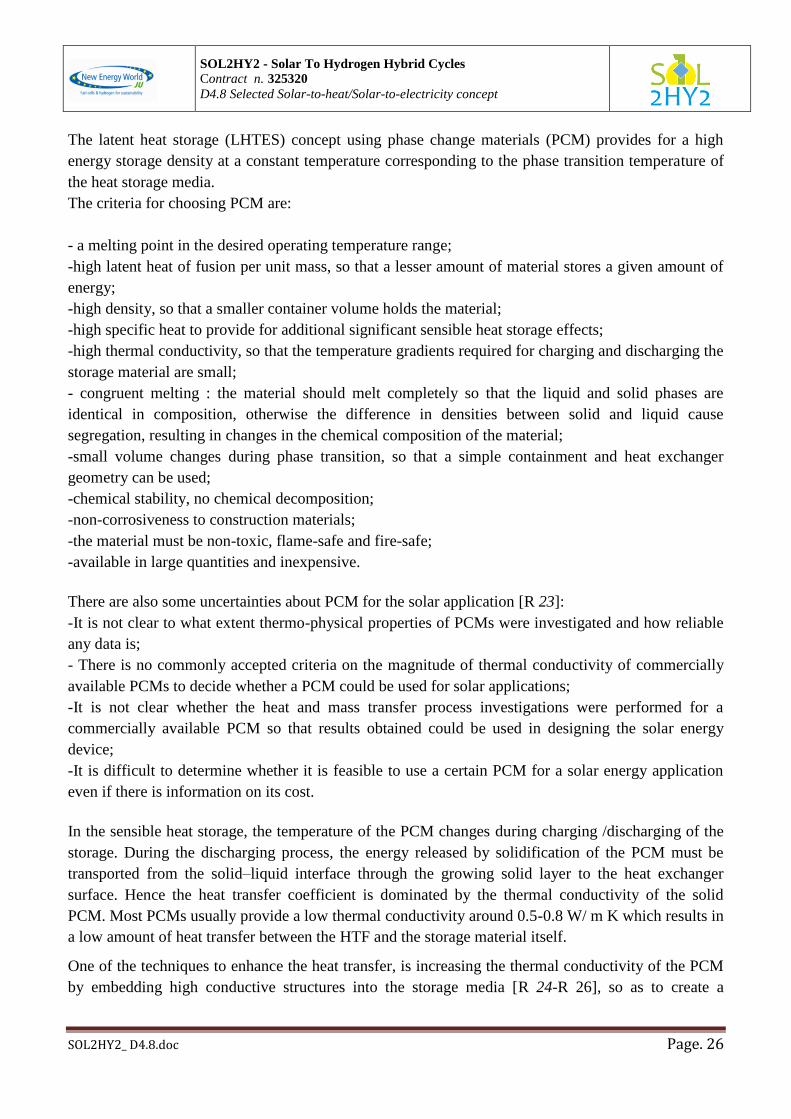
The latent heat storage (LHTES) concept using phase change materials (PCM) provides for a high
energy storage density at a constant temperature corresponding to the phase transition temperature of
the heat storage media.
The criteria for choosing PCM are:
- a melting point in the desired operating temperature range;
-high latent heat of fusion per unit mass, so that a lesser amount of material stores a given amount of
energy;
-high density, so that a smaller container volume holds the material;
-high specific heat to provide for additional significant sensible heat storage effects;
-high thermal conductivity, so that the temperature gradients required for charging and discharging the
storage material are small;
- congruent melting : the material should melt completely so that the liquid and solid phases are
identical in composition, otherwise the difference in densities between solid and liquid cause
segregation, resulting in changes in the chemical composition of the material;
-small volume changes during phase transition, so that a simple containment and heat exchanger
geometry can be used;
-chemical stability, no chemical decomposition;
-non-corrosiveness to construction materials;
-the material must be non-toxic, flame-safe and fire-safe;
-available in large quantities and inexpensive.
There are also some uncertainties about PCM for the solar application [R 23]:
-It is not clear to what extent thermo-physical properties of PCMs were investigated and how reliable
any data is;
- There is no commonly accepted criteria on the magnitude of thermal conductivity of commercially
available PCMs to decide whether a PCM could be used for solar applications;
-It is not clear whether the heat and mass transfer process investigations were performed for a
commercially available PCM so that results obtained could be used in designing the solar energy
device;
-It is difficult to determine whether it is feasible to use a certain PCM for a solar energy application
even if there is information on its cost.
In the sensible heat storage, the temperature of the PCM changes during charging /discharging of the
storage. During the discharging process, the energy released by solidification of the PCM must be
transported from the solid–liquid interface through the growing solid layer to the heat exchanger
surface. Hence the heat transfer coefficient is dominated by the thermal conductivity of the solid
PCM. Most PCMs usually provide a low thermal conductivity around 0.5-0.8 W/ m K which results in
a low amount of heat transfer between the HTF and the storage material itself.
One of the techniques to enhance the heat transfer, is increasing the thermal conductivity of the PCM
by embedding high conductive structures into the storage media [R 24-R 26], so as to create a

SOL2HY2 - Solar To Hydrogen Hybrid Cycles
Contract n. 325320
D4.8 Selected Solar-to-heat/Solar-to-electricity concept
SOL2HY2_ D4.8.doc Page. 27
composite material using nanoparticles (SiO2, TiO2, Al2O3, graphite) embedded in a molten salt base.
The addition of nanoparticles to a base salt results in an increase of PCM specific heat, thermal
conductivity and thermal diffusivity. ENEA characterized the thermo physical properties of the
composite material made of the binary mixture base (64NaNO3/36KNO3, %mol) by adding
nanoparticles in order to improve the solar contribution in terms of sensible heat storage (2-tank
storage trough systems) [R 27].
In the following are shortly described the experiments carried out, at laboratory scale, at the ENEA
Casaccia Labs.
Two different sized nanoparticles were dispersed in binary mixture base (64NaNO3/36KNO3, %mol),
the nitrates salts mixtures with the addition of nanoparticle are all prepared in the same manner. About
1 g of binary mixture base was dissolved in 13 ml of water (7ml) and ethanol (6ml) which contains a
specific amount (% by weight) of silica (SiO2) and titanium dioxide (TiO2) nanoparticles, the amount
of nanoparticles for each mixture is list in the Table 5. This solution was sonicated using a ultra
sonicator at 20 Hz for 30 min to obtain homogeneous dispersion of the nanofluids, after that the
water-ethanol solution was then rapidly evaporated. The SiO2 and TiO2 nanoparticles have dimensions
5 nm and 21 nm respectively. The heat capacity value of all the nanofluids and mixture base in the
liquid state were measured using a Differential scanning calorimeter (DSC), see Figure 17, with a
heating rate of 10 °C/min, the sample mass was about 50 mg and aluminium cruicibles with a lid were
used. The results in terms of heat capacity value are collected in table, in the temperature range 280-
400°C for binary mixture base and 260-400°C for the nanofluids. The measurement uncertainty in the
experiments is estimated to be in the range 1–17%. This shows further studies are needed.
In the case of samples with TiO2 (Figure 18) on the grain surface of salt, nanoparticles appear
relatively dispersed with aggregates of a few hundred nm.
Mixtures Heat capacity [J∙g∙°C] Enhancement
binary 1.6 ±0.17 /
binary base 1%TiO2 2 ±0.077 25%
binary base 3 %TiO2 1.6 ±0.01 0.6%
binary base 1 %SiO2 1.9 ±0.064 19%
binary base 3 %SiO2 1.9 ±0.038 19%
binary base 2%SiO2 2%TiO2 1.8 ±0.018 13%
Table 5: Average heat capacity values of the binary mixture base and nanofluids with SiO2 and TiO2.

SOL2HY2 - Solar To Hydrogen Hybrid Cycles
Contract n. 325320
D4.8 Selected Solar-to-heat/Solar-to-electricity concept
SOL2HY2_ D4.8.doc Page. 28
Figure 17: Average heat capacity values vs. temperature, on the left side nanofluid with 1%TiO2 (blu dots)
and nanofluid with 3% di TiO2 (black dots) in the temperature range 260-400°C, on the right side binary
mixture base in the temperature range 280-400°C.
Figure 18: Sem images of TiO2 nanoparticles on the grain surface, the dimension of aggregates are around
hundreds nm as order of magnitude, and the nanoparticles appear to be relatively dispersed.
Nevertheless some theoretical evaluations carried out by AALTO using FACTsage SW showed
addition of particles such as TiO2 might cause extra reactions, and it also shifts the liquidus line
(Figure 19), while addition of CaO particles should not present this advantage (Figure 20).

SOL2HY2 - Solar To Hydrogen Hybrid Cycles
Contract n. 325320
D4.8 Selected Solar-to-heat/Solar-to-electricity concept
SOL2HY2_ D4.8.doc Page. 29
Figure 19: phase diagram of NaNO3-KNO3 mixtures with TiO2 inclusions.
Figure 20: phase diagram of NaNO3-KNO3 mixtures with CaO inclusions.
Heat storage with hydrides
Hydrogen forms metal hydrides (MHn) with some metals and alloys leading to solid-state storage
under temperature and pressure, in general form the reaction is
SOL2HY2 - Solar To Hydrogen Hybrid Cycles
Contract n. 325320
D4.8 Selected Solar-to-heat/Solar-to-electricity concept
SOL2HY2_ D4.8.doc Page. 30
where M is metal, metal alloy, intermetallic compound.
The majority of metals, metal alloys and intermetallic compounds react directly with gaseous
hydrogen (reaction 1 from left to right) to form metal hydrides in an exothermal way, that is, with
release of heat (ΔH<0, heat recovery phase), backward there is the dissociation into metal and
hydrogen by heat absorption (ΔH>0, heat storage phase). This way thermal energy can be reversibly
stored as the heat of reaction of reversible chemical reactions. In order to apply this thermochemical
method to heat storage application [R 29] the magnesium hydride/magnesium system is particularly
suitable for this purpose, thus the reaction is
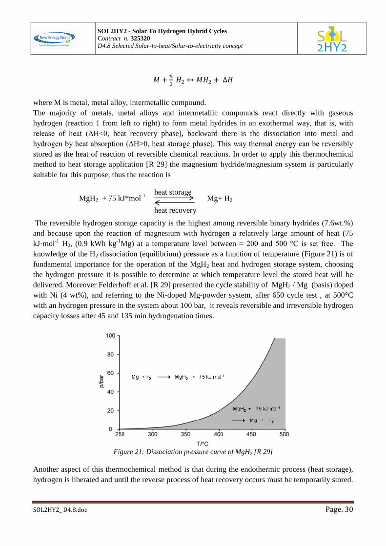
MgH2 + 75 kJ*mol-1
Mg+ H2
The reversible hydrogen storage capacity is the highest among reversible binary hydrides (7.6wt.%)
and because upon the reaction of magnesium with hydrogen a relatively large amount of heat (75
kJ·mol-1
H2, (0.9 kWh kg-1
Mg) at a temperature level between ≈ 200 and 500 °C is set free. The
knowledge of the H2 dissociation (equilibrium) pressure as a function of temperature (Figure 21) is of
fundamental importance for the operation of the MgH2 heat and hydrogen storage system, choosing
the hydrogen pressure it is possible to determine at which temperature level the stored heat will be
delivered. Moreover Felderhoff et al. [R 29] presented the cycle stability of MgH2 / Mg (basis) doped
with Ni (4 wt%), and referring to the Ni-doped Mg-powder system, after 650 cycle test , at 500°C
with an hydrogen pressure in the system about 100 bar, it reveals reversible and irreversible hydrogen
capacity losses after 45 and 135 min hydrogenation times.
Figure 21: Dissociation pressure curve of MgH2 [R 29]
Another aspect of this thermochemical method is that during the endothermic process (heat storage),
hydrogen is liberated and until the reverse process of heat recovery occurs must be temporarily stored.
heat storage
heat recovery

SOL2HY2 - Solar To Hydrogen Hybrid Cycles
Contract n. 325320
D4.8 Selected Solar-to-heat/Solar-to-electricity concept
SOL2HY2_ D4.8.doc Page. 31
Felderhoff et al. [R 29] presented a schematic representation of construction of MgH2/Mg heat stores,
one is with temporary storage of hydrogen in a pressure container; the other is temporary storage of
hydrogen in a low-temperature (LT) metal hydride, such as Mg2FeH6.
This last metal hydride/metal system (Mg2FeH6) presents higher stability in test cycle and a lower
hydrogen dissociation pressure (at 500°C 60 bar). While the MgH2/Mg system under different HT
conditions already loses capacity after 200-250 cycles (due to sintering), the Mg-Fe-H-systems, under
comparable conditions, show no signs of loss of capacity and reaction rates even after 600 or more
cycles.
Each configuration could be applied to warm water supply, production of ice or climatisation, they
also reported experimental results concerning the MgH2/Mg system for different fields of applications,
such as steam generator (400°C) and the combination of a solar-thermal power generator with a MgH2
heat accumulator.
In this case the main components were a “fixed focus concentrator” for solar radiation, a cavity
radiation receiver, a heat pipe system for heat transfer, a Stirling engine, a MgH2 store, a hydrogen
pressure or LT hydride store.
The concentrated solar heat is used to drive the Stirling engine and produce power. Simultaneously, a
more or less part of the solar heat is absorbed by the MgH2 heat store and the released hydrogen
streams in the pressure container or, alternatively, in the LT hydride store. In periods without or weak
solar irradiation the MgH2/Mg system cools down and the hydrogen flows back to the MgH2 store and
produces there high temperature heat and via Stirling engine electric power, see Figure 22.
An interesting comparison of the MgH2/Mg system with the existing heat storage system of Andasol 1
was made.

SOL2HY2 - Solar To Hydrogen Hybrid Cycles
Contract n. 325320
D4.8 Selected Solar-to-heat/Solar-to-electricity concept
SOL2HY2_ D4.8.doc Page. 32
Figure 22: Solar thermal-Hydrogen: on top during the day, on the bottom at night.
Andasol 1 is a solar thermal power plant located in Andalucia (Spain) with a 50 MWe steam turbine
for electricity production. To run the plant during the dark a heat storage system is installed for
additional 7.5 h electricity production at night. The storage system consists of two insulated storage
tanks each of these is 14 m high and 36 m in diameter. They are filled with 28,000 tons of a molten
salt mixture of sodium and potassium nitrate. The tanks are kept at different temperatures, the cold
tank at 260 °C and the hot tank at 390 °C. The overall storable heat amount in this system is 1,000
MWh.
The amount of heat released upon reaction of 1 kg of Mg with H2 is 0.9 kWh, thus it can be roughly
estimated that an amount of about 1,100 tons of Mg-metal would be able to store the same amount of
heat as the Andasol storage system. In addition to the storage of the Mg/MgH2 mixture, a second
container is necessary for the temporary storage of the hydrogen released during the dissociation of
MgH2. Furthermore Felderhoff et al. [R 29] as an example, assumed working temperatures of the heat
storage between 370 and 400 °C. At 370 °C the dissociation pressure of MgH2 is 10 bar and at 400 °C
roughly 20 bar (Figure 21). In this pressure and temperature ranges, a simple calculation shows a
volume of 109,000 m3 of H2 gas resulting from decomposition of MgH2 must be stored. In order to
better understand the benefit of this Mg/MgH2 storage it should be important to have an economic
evaluation of this system, but it is not so easy to find in literature the exact cost of this process,
because it is not yet applied at industrial scale.

SOL2HY2 - Solar To Hydrogen Hybrid Cycles
Contract n. 325320
D4.8 Selected Solar-to-heat/Solar-to-electricity concept
SOL2HY2_ D4.8.doc Page. 33
2.5 Electrical energy production
2.5.1 Electrical energy production by solar trough at medium temperature
An advantage of the use of Solar Trough technology to collect solar energy is the possibility to use the
same technology to transform heat to electricity used for the most classical and spread systems with
the only peculiarity to exchange heat by molten salts and water/steam. Also, in this way the generated
electricity does not give problems to the grid.
The power block, indeed, includes a conventional thermodynamic cycle consisting of steam turbines
(high-pressure and low-pressure ones), the exhaust steam cooling system (condenser), the electricity
generator (alternator), the electric transformer, and the electric connection to the grid. The molten salt
steam generator is the interface between the power block and the solar field including the heat storage
system.
The super-heated steam produced by the steam generator drives the high pressure (HP) turbine and
subsequently the medium-low pressure (MP-LP) turbine, after a re-heating phase.
The steam exhaust from the LP turbine enter the condenser and the resulting water is pumped into the
feed water pre-heating system to be recirculated into the steam generator. The feed water pre-heating
system includes the extraction pump from the condenser, low and high-pressure water pre-heaters,
water outgassing system, and the feed water circulation pump. An auxiliary steam generator is needed
to generate vacuum in the condenser and for the turbines' leak-tights during the plant start-up phase.
The heat sink of the condenser can be sea-water or fresh water from a river or lake. Wet or dry cooling
towers can be used if insufficient or no water is available. The design choice depends on the
characteristics of the site. The use of water from lakes, rivers and sea is the most convenient option
from the economic point of view. Cooling towers are significantly expensive, particularly dry cooling
towers.
The cycle is basically an Hirn one and considering a scheme shown in Figure 23 [R 28], it has been
constituted by:
-an exchanger ECON1 (economizer), which preheats water to be sent to the evaporator EVAP1. This
warming takes place using the molten salt residual heat.
- an evaporator EVAP1, which brings the water to saturation and vaporizes at a pressure of 100 bar;
- Two exchangers, SPHT1 SPHT2 (respectively: super-heater and re-heater), that overheat the steam
up to the maximum possible temperature (540 ° C) using the molten salt exiting the solar field at 550
°C. SPHT1 warms up the steam for the high-pressure turbine, while SPHT2 thinks to the steam for the
medium pressure turbine (ST2).
- two steam turbines, ST1 and ST2, for the power production and having intermediate steam
extractions, one in the case of ST1 and 4 for ST2. The first tapping of ST2 provides heat to the
degasser; the others, along with the outgoing stream from turbines provide the heat that preheat the
exchangers FWSH.
- 5 water exchangers (liquid / vapor) FHW. FHW2, FHW3 and FHW4 receive the heat from the ST2
steam extractions and warm the water coming from the condenser CND1 to be sent to the degasser.
FHW1 and FHW5, instead, receives the heat from the ST1 steam tapping and warm the water coming

SOL2HY2 - Solar To Hydrogen Hybrid Cycles
Contract n. 325320
D4.8 Selected Solar-to-heat/Solar-to-electricity concept
SOL2HY2_ D4.8.doc Page. 34
from the degasser to be sent to the economizer ECON1. The cold current from FHW1 and FHW5 goes
to the degasser, while the cold FHW2, FHW3 and FHW4 goes to the condenser.
- 1 capacitor CND1, which condenses the outgoing current from ST2.
- 2 pumps PMP1 and PMP2, that lead the water to the operating pressure of the heat exchangers steam
/ water.
- a valve V1, which provides for reducing the water pressure from the outgoing FWH2 until the
pressure in the condenser.
The simulations have shown that, as regards the efficiency of transformation heat / electric, a value of
40.7% in nominal conditions can be considered.
Figure 23 : solar throw power production scheme [source: R 28]
2.1.3 Steam solar power tower
The PS 10 solar power tower (Figure 24), works on a saturated steam concept: it stores heat in tanks
as superheated and pressurized water at 50 bar and 285°C. The water evaporates and flashes back to
steam, when pressure is lowered.
The receiver produces saturated steam at 40 bar 250ºC from thermal energy supplied by the
concentrated solar radiation flux. This receiver has a cavity design to reduce radiation and convection
losses. The steam is sent to the turbine, where it expands, producing mechanical work and electricity.
The turbo-generator output goes to a water-cooled 0.06 bar pressurized condenser. The condenser
output is preheated by 0.8 bar and 16 bar turbine extractions. The output of the first preheater is sent
to a degasser fed with steam from another turbine extraction. A third and last preheater is fed with

SOL2HY2 - Solar To Hydrogen Hybrid Cycles
Contract n. 325320
D4.8 Selected Solar-to-heat/Solar-to-electricity concept
SOL2HY2_ D4.8.doc Page. 35
steam coming from the receiver. This preheater increases the water temperature to 245ºC. This flow is
mixed with the flow of water returning from the drum, raising the temperature of water fed to the
receiver to 247ºC.
Figure 24: Solar plant PS10 in Spain
PS10 and PS20, are producing electricity from saturated steam since 2007 [R 4]. New projects by
Abengoa Solar, Brightsource, and eSolar demonstrate the feasibility of producing superheated steam
at above 500 °C with dual receivers [R 30].
Electrical efficiency of solar power towers
Characteristics of solar power towers are given in Table 6 taken from Romero et al. [R 4]. The values
are projections based on experiences with early commercial projects assuming future development.
Accordingly, central receiver systems can reach a solar-to-electricity conversion efficiency of up to
23 % and a net annual efficiency of 7–20 %, which is very much dependent on the location of the
power plant. Currently, a next generation of solar tower systems is under development with higher
process temperatures of more than 1000 °C applying new receivers with volumetric absorbers making
use of porous structures or particles. These power plants have the potential to reach higher electrical
efficiencies and are, moreover, applicable to processes for soar fuel production (e.g. hybrid sulphur
cycle). By this, the performance is expected to further increase.
Power unit 10-200 MWa
Temperature operation 565 °C
Annual capacity factor 20-77%a
Peak efficiency 23%
Net annual efficiency 7-20%a
Commercial status Early projects
Technology risk Medium
Thermal storage Yes
Hybrid schemes Yes a Data interval for the period 2010–2025
Table 6: Characteristics of central receiver systems [R 4]

SOL2HY2 - Solar To Hydrogen Hybrid Cycles
Contract n. 325320
D4.8 Selected Solar-to-heat/Solar-to-electricity concept
SOL2HY2_ D4.8.doc Page. 36
2.6 Concepts on size and thermal storage to couple the solar plants to the chemical plant.
In order to obtain a desired amount of hydrogen by the process, which SOL2HY2 has been working, a
definite quantity of energy is needed. This energy has to be provided in form of:
- daily continuous heat at medium temperature to feed the H2SO4 concentration;
- continuous heat for a specified number of hours for the vaporization of H2SO4;
- continuous heat for a specified number of hours for the H2SO4 cracking;
- continuous electrical energy for the H2 production by SDE (Sulphur dioxide depolarized
electrolysis/electrolyser) and for the BOP (Balance of Plant) equipments.
The amounts and modalities of these energy requests are being studied in the WP1 (Development of
the plants design), WP2 (SDE design), WP3 (Sulphuric acid concentrator and cracker) and WP5 (BOP
units).
In this WP, instead, the optimal energy integration for these different equipments has to be studied.
In particular there are some constrains concerning the modality and the kind of energy required:
- H2SO4 concentration must work in continuous for the whole day, due to the cost of equipments,
which have to work as long as possible for amortization optimization and mostly for the long time
of start-up and shut-down operations. Nevertheless the involved equipments should have
considerable drops in efficiency working with variable or intermittent streams in the place of the
nominal ones.
In this case the best option seems to be the MT heat production by the Solar Troughs CSP plants
supplied with a proper thermal storage able to assure the daily continuity of the H2SO4
concentration step. The requested temperature of 500 °C makes the best option for the use of
molten salts as thermal fluid.
- H2SO4 vaporization requires medium temperatures and continuity during the H2SO4 cracking step,
so it is not necessary the daily continuity. Since it has foreseen for this step a maximum
temperature of 500 °C, the Solar Troughs CSP plant seems to be the best solution for its better
efficiency.
- H2SO4 cracking requires high temperature and continuity during the SO2 production time, but it is
not necessary the daily continuity. In this case a CSP plant using Solar Central Receiver
technology is desirable. It should be supplied with a thermal storage able to assure the heat
continuity collection at least during the cracker working.
- SDE and BOP require electrical energy continuously for the whole time. In this case the best
options should be the use of the grid. Nevertheless, since the solar plants will produce, excess of
energy during the high irradiated periods (e.g. in summer), it could be considered the option to
produce electrical energy by this surplus to be sent in the grid in order to compensate the

SOL2HY2 - Solar To Hydrogen Hybrid Cycles
Contract n. 325320
D4.8 Selected Solar-to-heat/Solar-to-electricity concept
SOL2HY2_ D4.8.doc Page. 37
withdrawals of SDE and BOP. In this way it will be possible to produce an hydrogen produced by
an percentage of renewable source.
In order to optimize and verify the feasibility of this energy integration, different options concerning
location, choice of basic design and thermal storage size have to be considered.
First of all four different locations have been analyzed: Almeria (Spain, 36.84 N; 2.47 W), Larnaca
(Cyprus, 34.91 N 33.63 E); San Diego (USA, 28.13 N 15.43 W) and Alghero (Italy, 40.56 N 8.32 E)
and their DNI data for every hour of the year have been considered (source: METEONORM).
For each location and for each month it has been assessed the average of the all data corresponding at
the same hour of the day in order to have a typical day for every month of the year in every considered
location.
In Figure 25 some of these daily irradiation trend are shown and it is possible to verify as in South of
Europe the irradiation is very different in winter and in summer both in intensity and in number of
hours. This phenomenon is less evident in South California (San Diego) and it means large heat
collection in summer and only a few in winter for the South Europe in comparison of the South of
California.
0
100
200
300
400
500
600
0 5 10 15 20
DN
I (W
/m2
)
Hour
Almeria-January
0
100
200
300
400
500
600
0 5 10 15 20
DN
I (W
/m2
)
Hour
Almeria-June
0
200
400
600
800
0 5 10 15 20
DN
I (W
/m2
)
Hour
Larnaca-January
0
100
200
300
400
500
600
0 5 10 15 20
DN
I (W
/m2
)
Hour
Larnaca-June

SOL2HY2 - Solar To Hydrogen Hybrid Cycles
Contract n. 325320
D4.8 Selected Solar-to-heat/Solar-to-electricity concept
SOL2HY2_ D4.8.doc Page. 38
Figure 25: some examples of average daily DNIs
Choosing the daily requested irradiation collection (e.g: 20 MWh/d) and the desired percentage of
energy at medium temperature (e.g. 60 %) in continuous (e.g. 45 %) and in discontinuous, it is
possible to assess, for every location, the size of the solar field, the volume of the storage, the number
of collectors and for each hour of the day and for each month the amount of stored energy and the
quantity of energy to be sent to other users or to produce by a backup coming from other source. This
last case happens when the heat storage is not able to guarantee for whole day the requested energy
and it is mostly true during the winter time. Obviously it is possible to oversize the plant, but also the
cost increase in this way so it is necessary to find the best compromise and it is also depending on the
location. With this aim three different configurations can be selected, depending on the solar field
design, they are based on:
- Peak irradiation, this is the smaller configuration plant, because it is able to assure the requested
energy only for the high irradiated times, but it is also the cheapest solution.
- Average irradiation, this configuration is able to guarantee the heat continuously in yearly average
irradiation times.
- Minimum irradiation, this configuration is able to guarantee the heat continuously during the
whole year. Obviously, during some period having irradiation particularly low can be necessary a
backup integration. This solution is the most expensive, but can assure also a large production of
electrical energy during the summer.
0
200
400
600
800
0 5 10 15 20
DN
I (W
/m2
)
Hour
San Diego-January
0
200
400
600
800
0 5 10 15 20
DN
I (W
/m2
)
Hour
San Diego-June
0
100
200
300
400
500
0 5 10 15 20
DN
I (W
/m2
)
Hour
Alghero-January
0
200
400
600
800
0 5 10 15 20
DN
I (W
/m2
)
Hour
Alghero -June

SOL2HY2 - Solar To Hydrogen Hybrid Cycles
Contract n. 325320
D4.8 Selected Solar-to-heat/Solar-to-electricity concept
SOL2HY2_ D4.8.doc Page. 39
It is worth to notice that the MT solar plant using the solar trough technology is based on the use of a
series of collectors (generally six) to warm up the molten salt from 290 °C to 550 °C, so it should be
necessary to design the plant for at least about 3400 m2, which is the surface of six collectors. This
surface is able to produce energy of about 10 MWh/d in condition of yearly average irradiation in
South Europe. If the daily requested energy is lower, the plant will be oversized or will be necessary
to apply an artifice consisting in the following strategy.
During the start up, molten salts is warmed by its recycling into the solar field up to reach the desired
temperature of 550 °C. In order to guarantee the correct inlet temperature during the working part of
the cold molten salt from the cold tank (290 °C) has to be mixed with part of the outlet molten salt
stream at 550 °C as Figure 26 shows.
This warking way, obviously, introduces delays, better controls and higher costs so it is not desirable
to scale up the SOL2HY2 plant under the size to have a MT solar plant having too small solar field.
Obviously, if the size of the MT plant is under the size of one collector (about 566 m2) it is necessary
to build a collector different from the commercial ones with very high cost increasing.
Figure 26: small solar through plant concept
Table 7 shows four different designs based on the same daily energy, collection, medium temperature
energy fraction and its percentage request in continuous. The case studies 1, 2 and 3 for the same
location (Sardinia) have been sized basing the mirror surface on minimum, average or peak irradiance
respectively. It is possible to see the first case, able to guarantee the complete heat availability also in
December (Table 8), has the largest theoretical mirror field area, 4846 m2, so, in practice, includes 2
loops of 6 collectors for a real surface of 6797 m2
. In July (Table 9) it produces a lot of energy, which
is important to use for other applications and users. Case study 2, instead, is based on average yearly
irradiance and it does not assure energy for the plant for whole the day in the all months of the year, in
fact, in December, for example, it can provides the whole necessary heat only from 8 am to 17 pm

SOL2HY2 - Solar To Hydrogen Hybrid Cycles
Contract n. 325320
D4.8 Selected Solar-to-heat/Solar-to-electricity concept
SOL2HY2_ D4.8.doc Page. 40
(Table 10). Nevertheless it has a theoretical mirror field area of 2405 m2 and includes only one loop.
Case study 3, based on peak irradiance can provide MT heat to the H2 production plant only in the
most irradiated periods (i.e.: July), but also in May its collection is not enough to assure the continuity
(Table 11) and in December guarantees the continuity of the requested energy only from 8 am to 11
am. In this last case the surface has to be smaller than a complete loop, so 3 collectors are sufficient
and it is necessary to use the strategy shown in Figure 26. Obviously storage tanks volumes will be
bigger for the first cast and smaller in the third one. To establish the best solution it is important to
confront the energy price (surely higher in the first case) and the possibility to use the excess of
energy. If other users can utilize the heat excess, probably the first solution is the best. The third
solution, instead, is more convenient if only a percentage of renewable energy is requested, because
heat from other sources is available. Finally, the last case study has been chosen to compare a plant,
able to assure the same energy production (based on minimum irradiance), built in Sardinia or in San
Diego. In the last case the plant can use only a loop and a thermal storage is an half. It shows how
much can be convenient to build this kind of plant in high irradiated counties.
Scenario 1 2 3 4
Total Thermal daily energy collection 20 20 20 20 MWh/d
Direct solar radiation time 8 8 8 8 h
Total Thermal Power Direct irradiance 2.5 2.5 2.5 2.5 MW
MT Thermal storage 16 16 16 16 h
HT Thermal storage 0 0 0 0 h
Medium Temperature energy fraction 60 60 60 60 %
MT Heat Collection efficiency 0.52 0.52 0.52 0.52
HT Heat Collection efficiency 0.4 0.4 0.4 0.4
MT Thermal production 6.24 6.24 6.24 6.24 MWh/d
MT Thermal production in continuous (%) 45 45 45 45 %
MT Thermal production in continuous 2.808 2.808 2.808 2.808 MWh/d
HT Thermal production 3.2 3.2 3.2 3.2 MWh/d
Total Thermal daily Energy Production 9.4 9.4 9.4 9.4 MWh/d
Location Sardinia Sardinia Sardinia San Diego
Mirror surface based on Minimum Average Peak Minimum
DNI - selected 2.48 4.99 7.63 4.63 kWh/m2/d
MT Theoretical Mirror field area 4845.7 2404.6 1573.0 2593.8 m2
Collection surface of the collector 566.4 566.4 566.4 566.4 m2
Number of collectors for a loop 6 6 3 6
Loop surface 3398.4 3398.4 1699.2 3398.4 m2
Number of loops 2 1 1 1
Mirror surface 6796.8 3398.4 1760 4821 m2
Max heat stored 10971 5816 2601 5523 kWh
Volume of storage hot solar tank 77 37 16 35 m3
Volume of storage cool solar tank 71 33 15 32 m3
Start discontinuous MT production 11 11 11 11 h

SOL2HY2 - Solar To Hydrogen Hybrid Cycles
Contract n. 325320
D4.8 Selected Solar-to-heat/Solar-to-electricity concept
SOL2HY2_ D4.8.doc Page. 41
End discontinuous MT production 18 18 18 18 h
Table 7: Different MT solar plant sizes varying mirror surface modality or location
h Plant production Ch Plant
consumption Heat stored
Heat
available(st+prod)
Other
users
Wh Wh Wh
for plant
consumption Wh
0 0 117000 1551812 117000 104687
1 0 117000 1330125 117000 104687
2 0 117000 1108437 117000 104687
3 0 117000 886750 117000 104687
4 0 117000 665062 117000 104687
5 0 117000 443375 117000 104687
6 0 117000 221687 117000 104687
7 0 117000 0 117000 104687
8 559907 117000 338220 117000 104687
9 1075122 117000 1191655 117000 104687
10 1232343 117000 2202310 117000 104687
11 1252067 546000 2803690 546000 104687
12 1225731 546000 3378733 546000 104687
13 1164051 546000 3892096 546000 104687
14 1071474 546000 4312883 546000 104687
15 827377 546000 4489572 546000 104687
16 344427 546000 4183311 546000 104687
17 0 546000 3532624 546000 104687
18 0 546000 2881936 546000 104687
19 0 117000 2660249 117000 104687
20 0 117000 2438562 117000 104687
21 0 117000 2216874 117000 104687
22 0 117000 1995187 117000 104687
23 0 117000 1773499 117000 104687
Table 8: Energy production, storage, consumption and availabilities for case 1 in December.
h Plant production Ch Plant
consumption Heat stored
Heat
available(st+prod)
Other
users
Wh Wh Wh
for plant
consumption Wh
0 0 117000 4645417 117000 863406
1 0 117000 3665011 117000 863406
2 0 117000 2684606 117000 863406
3 0 117000 1704200 117000 863406
4 0 117000 723794 117000 863406
5 170902 117000 0 117000 863406
6 1066115 117000 85710 117000 863406
7 1717003 117000 736597 117000 863406
8 2064280 117000 1820472 117000 863406

SOL2HY2 - Solar To Hydrogen Hybrid Cycles
Contract n. 325320
D4.8 Selected Solar-to-heat/Solar-to-electricity concept
SOL2HY2_ D4.8.doc Page. 42
9 2204742 117000 3044808 117000 863406
10 2322401 117000 4386803 117000 863406
11 2379178 546000 5356575 546000 863406
12 2379634 546000 6326803 546000 863406
13 2347711 546000 7265109 546000 863406
14 2329925 546000 8185629 546000 863406
15 2351816 546000 9128038 546000 863406
16 2167574 546000 9886207 546000 863406
17 1934422 546000 10411223 546000 863406
18 1237930 546000 10239747 546000 863406
19 288105 117000 9547446 117000 863406
20 0 117000 8567040 117000 863406
21 0 117000 7586635 117000 863406
22 0 117000 6606229 117000 863406
23 0 117000 5625823 117000 863406
Table 9: Energy production, storage, consumption and availabilities for case 1 in July.
h Plant production Ch Plant
consumption Heat stored
Heat
available(st+prod)
Other
users
Wh Wh Wh
for plant
consumption Wh
0 0 117000 0 0 0
1 0 117000 0 0 0
2 0 117000 0 0 0
3 0 117000 0 0 0
4 0 117000 0 0 0
5 0 117000 0 0 0
6 0 117000 0 0 0
7 0 117000 0 0 0
8 279954 117000 162954 117000 0
9 537561 117000 583515 117000 0
10 616172 117000 1082686 117000 0
11 626034 546000 1162720 546000 0
12 612865 546000 1229585 546000 0
13 582025 546000 1265610 546000 0
14 535737 546000 1255347 546000 0
15 413688 546000 1123036 546000 0
16 172213 546000 749249 546000 0
17 0 546000 203249 546000 0
18 0 546000 0 203249 0
19 0 117000 0 0 0
20 0 117000 0 0 0
21 0 117000 0 0 0
22 0 117000 0 0 0
23 0 117000 0 0 0
Table 10: Energy production, storage, consumption and availabilities for mirror surface based on average DNI
in Sardinia, in December.

SOL2HY2 - Solar To Hydrogen Hybrid Cycles
Contract n. 325320
D4.8 Selected Solar-to-heat/Solar-to-electricity concept
SOL2HY2_ D4.8.doc Page. 43
h Plant production Ch Plant
consumption Heat stored
Heat
available(st+prod)
Other
users
Wh Wh Wh
for plant
consumption Wh
0 0 117000 0 0 0
1 0 117000 0 0 0
2 0 117000 0 0 0
3 0 117000 0 0 0
4 0 117000 0 0 0
5 62164 117000 0 62164 0
6 278985 117000 161985 117000 0
7 404710 117000 287710 117000 0
8 446352 117000 617062 117000 0
9 490133 117000 990195 117000 0
10 484147 117000 1357342 117000 0
11 459578 546000 1270920 546000 0
12 468756 546000 1193675 546000 0
13 472746 546000 1120421 546000 0
14 469981 546000 1044402 546000 0
15 472774 546000 971177 546000 0
16 409071 546000 834248 546000 0
17 325159 546000 613407 546000 0
18 211519 546000 278925 546000 0
19 0 117000 161925 117000 0
20 0 117000 44925 117000 0
21 0 117000 0 44925 0
22 0 117000 0 0 0
23 0 117000 0 0 0
Table 11: Energy production, storage, consumption and availabilities for case 3 in May.
h Plant production Ch Plant
consumption Heat stored
Heat
available(st+prod)
Other
users
Wh Wh Wh
for plant
consumption Wh
0 0 117000 0 0 0
1 0 117000 0 0 0
2 0 117000 0 0 0
3 0 117000 0 0 0
4 0 117000 0 0 0
5 0 117000 0 0 0
6 0 117000 0 0 0
7 0 117000 0 0 0
8 139977 117000 22977 117000 0
9 268781 117000 174757 117000 0
10 308086 117000 365843 117000 0
11 313017 546000 132860 546000 0

SOL2HY2 - Solar To Hydrogen Hybrid Cycles
Contract n. 325320
D4.8 Selected Solar-to-heat/Solar-to-electricity concept
SOL2HY2_ D4.8.doc Page. 44
12 306433 546000 0 439293 0
13 291013 546000 0 291013 0
14 267868 546000 0 267868 0
15 206844 546000 0 206844 0
16 86107 546000 0 86107 0
17 0 546000 0 0 0
18 0 546000 0 0 0
19 0 117000 0 0 0
20 0 117000 0 0 0
21 0 117000 0 0 0
22 0 117000 0 0 0
23 0 117000 0 0 0
Table 12: Energy production, storage, consumption and availabilities for case 3 in December.
2.7 Materials and structures.
The STH system is comprised of several materials. Depending on the design, an external metal case, a
quartz window, an internal structural material for holding in place the absorber material, and the
absorber material itself are the main components of a receiver. Of these materials, the most critical is
likely the absorber material, as it is exposed to the highest thermal stresses and critical for the
performance of the STH unit.
The absorber material for the designs considered in Sol2hy2 needs to be of porous nature in order to
have a flow passing through it. It is exposed to concentrated solar radiation that generate high
temperatures, and the collected heat needs to be transferred to the medium flowing through it in an
efficient manner without creating critical pressure drops. Considering these basic requirements, the
absorber material should be high temperature stable, demonstrate good resistance to thermal shocks,
and have a high thermal conductivity. Moreover, to obtain high efficiencies, the material needs to
have high absorptivity in the visible and near infrared range and large surface area for convective heat
transfer from the solid to the fluid [R 31].
Several materials have been tested in the past for their performance as volumetric absorbers. A good
overview is given by Fend et Al. (2004), where four main material classes are tested and ranked
against each other. Silicon carbide foams, SiC fibre meshes, ceramic and metallic catalyst carriers
(honeycombs) have been investigated for their efficiencies and usability in a volumetric receiver. The
study reports the ceramic foams and fabrics as the most promising materials because of their potential
towards large specific surface combined with beneficial pressure loss characteristics.
Erbicol’s standard material is a 10PPI silicon-infiltrated ceramic foam used in porous burners, as
depicted in Figure 27. The high temperature stability and thermal shock resistance has been
demonstrated for porous burners [R 32], and with a material thermal conductivity of about 110 W/mK
(@ 20°C) the characteristics are suitable for the material to be used as solar absorber.

SOL2HY2 - Solar To Hydrogen Hybrid Cycles
Contract n. 325320
D4.8 Selected Solar-to-heat/Solar-to-electricity concept
SOL2HY2_ D4.8.doc Page. 45
Figure 27: Standard 10 PPI SiSiC foam used in a porous burner. Right: SiSiC foam at RT; Left: SiSiC foam at
1350°C.
Concerning the architecture of the porosity, a standard foam is a random distribution of Kelvin cells.
The pore geometry is derived from the polyurethane template used in the replica technique to
manufacture the foams. While this geometry offers several benefits, one drawback is the fixed
porosity for each foam. For solar absorber materials, it has been shown [R 31] that a gradient porosity
can be beneficial to increase the performance of the receiver while keeping the pressure drop below
critical values. To solve this issue with random foams Erbicol joined several foams slices with
different porosity during the green stage of the ceramization process (Figure 28). This results in a
stepwise porosity gradient that should demonstrate behavior similar to a continuous porosity gradient.
Future work will concentrate on the design and manufacturing of regular lattice structures with
continuous porosity gradient.
Figure 28: Left: SiSiC foam assembly showing a stepwise gradient from 10 ppi to 30 ppi. Right: SiSiC
elongated Kelvin cell lattice comparable to 10 ppi.

SOL2HY2 - Solar To Hydrogen Hybrid Cycles
Contract n. 325320
D4.8 Selected Solar-to-heat/Solar-to-electricity concept
SOL2HY2_ D4.8.doc Page. 46
2.8 MCDM of different options.
Given a set of alternatives (solutions) and a set of decision criteria, it is important to establish what is
the best option. In multiple-criteria design problems (multiple objective mathematical programming
problems) the alternatives are not explicitly known. An alternative can be found by solving a
mathematical model. The number of alternatives is either infinite and not countable (when some
variables are continuous) or typically very large if countable (when all variables are discrete).
As in the case of the SOL2HY2 project, it is very uncommon to tackle problems concerning only a
single objective when dealing with real-world industrial applications: generally multiple, often
conflicting, objectives arise naturally in most practical optimization problems; thus several multi-
objective optimization methods have been developed. Many of these algorithms are based on a
stochastic search approach such as evolution algorithms, simulated annealing and genetic algorithms.
Optimizing a problem means finding a set of decision variables which satisfies constraints and
optimizes simultaneously a vector function. The elements of the vector represent the objective
functions of all decision makers. This vector optimization leads to a non-unique solution of the
problem.
For example, as shown in the figure, for the selection of the best hydrogen production process one has
to maximize efficiency and availability, minimize costs, environmental threats, complexity and
process feasibility at the same time.
Figure 29: example of selection of the best hydrogen production process.
Here we consider, without loss of generality, the minimization of two objectives all equally important,
where no additional information about the problem is available.
A solution of the problem can be described by a “decision vector” ⃗ of the form ⃗ ( ) lying
in the design space . The evaluation of the two objective functions on ⃗ produces a solution ⃗
( ) in the objective space , i.e. is a vector map of the form: .

SOL2HY2 - Solar To Hydrogen Hybrid Cycles
Contract n. 325320
D4.8 Selected Solar-to-heat/Solar-to-electricity concept
SOL2HY2_ D4.8.doc Page. 47
Figure 30: multiobjective optimization according to Pareto criteria.
Comparing two solutions ⃗ and ⃗ requires to define a dominance criteria. In modern multiobjective
optimization the Pareto criteria is the most used. This criteria states:
- An objective vector ⃗ is said to dominate another objective vector ⃗ (i.e., ⃗ ⃗ ) if no
component of ⃗ is greater than the corresponding components of ⃗ and at least one
component is greater;
- accordingly, the solution ⃗ dominates ⃗ , if ( ⃗ ) dominates ( ⃗ );
- all non-dominated solutions are the optimal solutions of the problem, solutions not dominated
by any others. The set of these solutions is named Pareto set while its image in objective space
is named Pareto front.
A generic multiobjective optimization solver searches for non-dominated solutions that correspond to
trade-offs between all the objectives. The utopia (or ideal) point corresponds to the minimal of all the
objectives and typically is not a real and feasible point.
Figure 31: utopia point concept.
When optimization has been performed and the Pareto front has been computed it is necessary to
choose the design point of the system, namely how the system should be made. Many different design
points exist each for a different point of the Pareto front and moreover two closed points in the Pareto
front does not mean that have the corresponding design points closed.
Genetic algorithms [R 33] are search methods based on the mechanics of natural evolution and
selection. These methods are widely used for solving highly non-linear real problem because of their

SOL2HY2 - Solar To Hydrogen Hybrid Cycles
Contract n. 325320
D4.8 Selected Solar-to-heat/Solar-to-electricity concept
SOL2HY2_ D4.8.doc Page. 48
ability of being robust against noisy and local optima. Genetic algorithms are largely used in real-
world problems as well as in a number of engineering applications that were hard to solve with
“classical” methods.
EnginSoft is creating a mathematical model of the plant considering the different options to couple
solar electricity and solar heat to the cycles and to cover the electricity demand of the electrolyser as
well as of the BoP components. Multi-objective optimization will be performed on such a model,
taking advantage of the NSGA-II, the second version of the famous “Non-dominated Sorting Genetic
Algorithm” based on the work of Prof. Kalyanmoy Deb [R 34]. NSGA-II is a fast and elitist multi-
objective evolutionary algorithm.

SOL2HY2 - Solar To Hydrogen Hybrid Cycles
Contract n. 325320
D4.8 Selected Solar-to-heat/Solar-to-electricity concept
SOL2HY2_ D4.8.doc Page. 49
3. Conclusions
In order to select the optimized STH/STE configurations, different concepts have been proposed and
evaluated. A literature research on solar tower technologies to provide high temperature heat >600 °C
for sulphuric acid cracking with special focus on thermal storage options has been performed.
Concerning medium temperature technology devoted to power the sulphuric acid concentration step in
continuous and its vaporization up to 500 °C, the solar trough technology has been considered using
also the large experience acquired by ENEA on R&D of solar trough plant using molten salts as
thermal vectors and thermal storage mean.
Some innovations have been also considered for the thermal storage trough this technology: system
based on a single tank designed to use the vertical thermal stratification profile in the HSM fluid; the
utilization of nanoparticles inclusions in the salts (CaO, TiO2, etc), which could improve its heat
capacity but need more experimentation to demonstrate the absence of secondary reactions. PCM
might be another option, if the latent heat and materials costs were beneficial vs. molten nitrates and
the case of MgH2 has been discussed.
Furthermore the methods and the efficiency to generate electricity by CSP both at high temperature
and at medium has been described.
Concerning the medium temperature different scenarios have been assessed based on the following
input: thermal power production, hourly direct normal irradiance (kWh/m2/d) throughout the year,
basic design option based on peak, annual average or minimum DNI values. Some of the above listed
input are site specific, therefore 4 specific locations have been considered, namely: Almeria (Spain),
Larnaca (Cyprus), Alghero (Italy) and San Diego (USA).
The main outputs obtained for each scenario are: mirror field surface, thermal storage size, salt
consumption, backup energy integration and thermal energy supply exceeding SAC needs.
From the analysis, it has been deduced that at low total solar energy input low total solar energy input,
and therefore low mirror surfaces (< 3400 m2), the conventional configuration of parabolic trough
CSP plant cannot be used. Therefore, a specific design to be used for low capacity CSP plant has
been proposed.
This assessment will serve as the basic input for Task 4.2 and techno economic assessment in WP6.
Relating to HT, volumetric receivers applying porous or particle absorbers were identified as
candidate designs. Both receiver concepts can be equipped with storage systems to compensate for up
to several hours without solar radiation. In addition, to storage tanks for sulphuric acid and sulphur
dioxide a more continuous operation could be achieved.
For solar heat collection different receiver designs have been analyzed and porous SiC manufacturing
technology has been evaluated with different framework topologies. These ceramic structures were
compared with known ceramic materials and the advantages of SiC have been demonstrated.
Finally MCDM concepts have been presented as useful instrument to manage the large number of
variables related to SOL2HY2 virtual plant and to know its best optimization.
SOL2HY2 - Solar To Hydrogen Hybrid Cycles
Contract n. 325320
D4.8 Selected Solar-to-heat/Solar-to-electricity concept
SOL2HY2_ D4.8.doc Page. 50
4. Acronyms
ANI Aperture Normal Irradiance
BOP Balance of Plant
CSP Concentrated Solar Power
DC Direct Current
DNI Direct Normal Irradiance
DSC Differential Scanning Calorimeter
EOR Enhanced Oil Recovery
FR Fresnel Reflector
HP High Pressure
HSM Heat Storage Material
HT High Temperature
HTF Heat Transfer Fluid
LHTES Latent Heat Thermal Energy Storage
MCDM Multiple-Criteria Decision Making
MENA Middle East and North Africa
MH Metal Hydrides
MP Medium Pressure
MT Medium Temperature
PCM Phase Change Material
PCS Solar Collectors Proof
PT Parabolic Trough
SCA Solar Collector Assembly
SD Solar Dish
SDE Sulphur dioxide depolarized electrolysis/electrolyser
SEGS Solar Energy Generating Systems
SG Steam Generator
SOL2HY2 Solar To Hydrogen Hybrid Cycles
ST Solar Tower
STE Solar to Electricity
STH Solar to Heat
SW Software
TES Thermal Energy Storage
WP Work Package

SOL2HY2 - Solar To Hydrogen Hybrid Cycles
Contract n. 325320
D4.8 Selected Solar-to-heat/Solar-to-electricity concept
SOL2HY2_ D4.8.doc Page. 51
5. References
R 1 Kuravi, S., et al., Thermal energy storage technologies and systems for concentrating solar
power plants. Progress in Energy and Combustion Science, 2013. 39(4): p. 285-319.
R 2 Richter, C., S. Teske, and R. Short, Concentrating Solar Power, Global outlook 2009.
R 3 Barlev, D., R. Vidu, and P. Stroeve, Innovation in concentrated solar power. Solar Energy
Materials and Solar Cells, 2011. 95(10): p. 2703-2725.
R 4 Romero, M. and A. Steinfeld, Concentrating solar thermal power and thermochemical fuels.
Energy & Environmental Science, 2012. 5(11): p. 9234-9245.
R 5. www.solarpaces.org/csp-technology.
R 6 Romero, M. and A. Steinfeld, Concentrating solar thermal power and thermochemical fuels.
Energy & Environmental Science, 2012. 5(11): p. 9234.
R 7 Zunft, S., et al., Jülich Solar Power Tower—Experimental Evaluation of the Storage
Subsystem and Performance Calculation. Journal of Solar Energy Engineering 2011. 133(3): p.
0310193-1:031019-5.
R 8 Schmitz, M., et al., Assessment of the potential improvement due to multiple apertures in
central receiver systems with secondary concentrators. Solar Energy, 2006. 80(1): p. 111-120.
R 9 Kolb, G.J. and R.B. Diver, Screening Analysis of Solar Thermochemical Hydrogen Concepts,
2008, Sandia National Laboratories.
R 10 Pitz-Paal, R., J. Dersch, and B. Milow, ECOSTAR - European Concentrated Solar Thermal
Road-Mapping.
R 11 European Academies Science Advisory Council (EASAC), Concentrating solar power: its
potential contribution to a sustainable energy future2011.
R 12 Dunn, R.I., P.J. Hearps, and M.N. Wright. Molten-salt power towers: newly commercial
concentrating solar storage. in IEEE. 2012.
R 13 http://www.nrel.gov/csp/solarpaces/project_detail.cfm/projectID=38.
R 14 http://www.renewableenergyfocus.com/view/17095/csp-developments-in-heat-transfer-and-
storage-materials/.
R 15 Gaggioli et. Al - An innovative concept of a thermal energy storage system based on a single
tank configuration using stratifying molten salts as both heat storage medium and heat transfer fluid,
and with an integrated steam generator – Solar Paces (2013).
R 16 A. Felix Regin, Heat transfer characteristics of thermal energy storage system using PCM
capsules: A review, Renewable and Sustainable Energy Reviews 12 (2008) 2438–2458.
R 17 Murat Kenisarin, Khamid Mahkamov Solar energy storage using phase change materials,
Renewable and Sustainable Energy Reviews 11 (2007) 1913–1965.

SOL2HY2 - Solar To Hydrogen Hybrid Cycles
Contract n. 325320
D4.8 Selected Solar-to-heat/Solar-to-electricity concept
SOL2HY2_ D4.8.doc Page. 52
R 18 A. Abhat, Low Temperature latent heat thermal energy storage: heat storage materials, Solar
Energy Vol. 30, No. 4. pp 313-332 1983.
R 19 Murat M. Kenisarin, High-temperature phase change materials for thermal energy storage,
Renewable and Sustainable Energy Reviews 14 (2010) 955–970.
R 20 Belen Zalba, José Ma Marın, Review on thermal energy storage with phase change: materials,
heat transfer analysis and applications, Applied Thermal Engineering 23 (2003) 251–283.
R 21 Anant Shukla, D. Buddhi Solar water heaters with phase change material thermal energy storage
medium: A review, Renewable and Sustainable Energy Reviews 13 (2009) 2119–2125.
R 22 Marc Medrano, Antoni Gil, State of the art on high-temperature thermal energy storage for
power generation. Part 2—Case studies, Renewable and Sustainable Energy Reviews 14 (2010) 56–
72.
R 23 Rainer Tamme,y, Thomas Bauer, Latent heat storage above 120°C for applications in the
industrial process heat sector and solar power generation,Int. J. Energy Res. 2008; 32:264–271.
R 24 S. Pincemina, R. Olives, Highly conductive composites made of phase change materials and
graphite for thermal storage, Solar Energy Materials & Solar Cells 92 (2008) 603–613.
R 25 Hani Tiznobaik, Donghyun Shin, Enhanced specific heat capacity of high-temperature molten
salt-based nanofluids, International Journal of Heat and Mass Transfer 57 (2013) 542–548.
R 26 Donghyun Shin, Debjyoti Banerjee, Enhanced Specific Heat Capacity of Nanomaterials
Synthesized by Dispersing Silica Nanoparticles in Eutectic Mixtures.
R 27 Miliozzi A, Veca E, Sau S, Grena R, Celino M, Falconieri M, Rondino F, Individuazione e
caratterizzazione di miscele di materiali a cambiamento di fase e nanoparticelle da impiegare come
sistemi alternativi di accumulo termico. Report RdS/2013/079.
R 28 Crescenzi T, Fontanella A, Liberatore R, Metelli E, Russo V. Analisi tecnico-economica di
impianti solari a collettori parabolici lineari con differenti fluidi di lavoro. Report RdS/2013/077
R 29 Felderhoff M, Bogdanovic’ B. High temperature metal hydrides as heat storage materials for
solar and related applications, International journal of molecular sciences , 10: 325-344.
R 30 Romero, M. and J.G. Aguilar, Energy & Power Generation Handbook, A. K. R. Rao, Editor
2011: Three Park Avenue, New York, NY 10016-5990, USA.
R 31 Fend et Al., Porous materials as open volumetric solar receivers: Experimental determination of
thermophysical and heat transfer properties, Energy, 29, 5-6, pp. 823-833, 2003, doi: 10.1016/S0360-
5442(03)00188-9.
R 32 Ortona et Al., Aging of reticulated Si–SiC foams in porous burners, Advances in Applied
Ceramics, Volume 109, Issue 4, pp. 246-251, 2010, doi: 10.1179/174367510X12663198542586.
R 33 David E. Goldberg. Genetic Algorithms in Search, Optimization & Machine Learning. Addison-
Wesley, 1989

SOL2HY2 - Solar To Hydrogen Hybrid Cycles
Contract n. 325320
D4.8 Selected Solar-to-heat/Solar-to-electricity concept
SOL2HY2_ D4.8.doc Page. 53
R 34 Deb, K., Pratap. A, Agarwal, S., and Meyarivan, T. (2002). A fast and elitist multi-objective
genetic algorithm: NSGA-II. IEEE Transaction on Evolutionary Computation, 6(2), 181-197

SOL2HY2 - Solar To Hydrogen Hybrid Cycles
Contract n. 325320
D4.8 Selected Solar-to-heat/Solar-to-electricity concept
SOL2HY2_ D4.8.doc Page. 54
Coordinator: Stefano Odorizzi, ENGINSOFT SpA
Via della Stazione,27 38123 – Trento (ITALY)
Tel: +39 0461 915391 Fax: +39 0461979201
e-mail: [email protected]
Coordinator Main Contact: Carla Baldasso, ENGINSOFT SpA
Via Giambellino, 7 35129 – Padova (ITALY)
Tel: +39 049 7705311 Fax: +39 0461979201
e-mail: [email protected]
Responsible partner for this deliverable: Raffaele Liberatore, ENEA
Via Anguillarese, 301 00123 – Rome (ITALY)
Tel: +39 06 30484035 Fax: +39 0630486779
e-mail: [email protected]