Clipsal HomeMinder Home Automation System...Clipsal HomeMinder Home Automation System ... 1 1 ...

Selected Home Automation and Home Security Realizations: An Improved Architecture 43
Selected Home Automation and Home Security Realizations: An Improved Architecture
K. Balasubramanian and A. Cellatoglu
X
Selected Home Automation and Home Security Realizations: An Improved Architecture
K. Balasubramanian and A. Cellatoglu
European University of Lefke North Cyprus, Turkey
1. Abstract
The main objective of this presentation is to give the design of main equipments for intelligent home meeting the modern requirements and satisfying most living standards of consumers. In this endeavor the home automation considerations of this presentation focus on manual and remote control of selected appliances, timed setting of switching the appliances and personal digital home assistant software that brings the attention of the resident about the tasks of the day to be performed. Home security concerns of the system are the incorporation of i. real time audio visual system that permits regulated admittance of the visitors after approval from the resident and ii. remote alerting the resident upon detecting the fire or intruder. The design approach is based on the support of the central web server and monitoring unit and is meant for medium sized residential complex constituting many flats. In order to self support the energy needs of the flats to an extent a cost effective dual energy extraction unit generating electricity from the renewable energy resources is also included in the system and fixed in each flat. The performance of all schemes presented here are compared and analysed for their adaptation to any installation. The hardware devices and components used are commonly available in practice and the realization of the system for any further expanded requirements would be quite feasible and easy.
2. Introduction
Home automation activities are becoming increasingly important nowadays in providing more comfort and security for the home residents. Reports are available in the past concerning the development of devices and units needed for implementing the smart home (two websites, 2009; Jorge Caleira Nunes et al, 2004; Renato Nunes, 2003 and Balasubramanian and Cellatoglu, 2008). Each implementation deals certain aspects of automation satisfying partial requirements of the consumers. This project deals with the design of home automation apparatus satisfying essential requirements of automation needed for comfortable stay and pleasant living in a flat of multi storied building. Also, generating electrical energy from natural resources and their utilization schemes for feeding the apparatus are implemented in the system as to promote contributing to alternate energy
3
www.intechopen.com
Smart Home Systems44
resources and to reduce the cost constraints of energy consumption. These schemes are designed to extract maximum solar and wind energy and used to feed selected appliances of the residential flat. In the absence of sun and wind energy the power system lines supplying electricity to the flat would take care of powering the selected appliances. Furthermore, as an additional security concern, an intruder detection system is installed in the system which when detects an intruder would dial automatically a sequence of digits programmed in the system as to give remote intimation for the intrusion found. As internet and telephone communication are quite popularly used nowadays, remote control schemes of selected appliances in flat are also included in the system as to serve the day to day urgent needs and also for security concerns. This scheme facilitates the control of appliances distributed in the flat by operating from any other room. Furthermore, a Home Assistant software installed in the system refers the home data base every morning and brings the list of activities to be performed on that day to screen as to alert the user to be ready for solving the issues of the day. The software cannot be accessed by any unknown person due to password requirement. Necessary firewall is incorporated in the web server as to avoid further interruptions due to unauthorized interruption and to block viruses.
3. Selected Remote Control Techniques
The control techniques which are most viable and for easy implementation to home automation system are presented here.
3.1 Web Based Control Internet usage has become a common means of sharing and exchanging information between users. By activating web page setup for remote control purposes we can selectively issue commands to switch ON or OFF the selected appliances in home. This is an active method of controlling the appliances wherein command can be issued after knowing the status of the appliance.
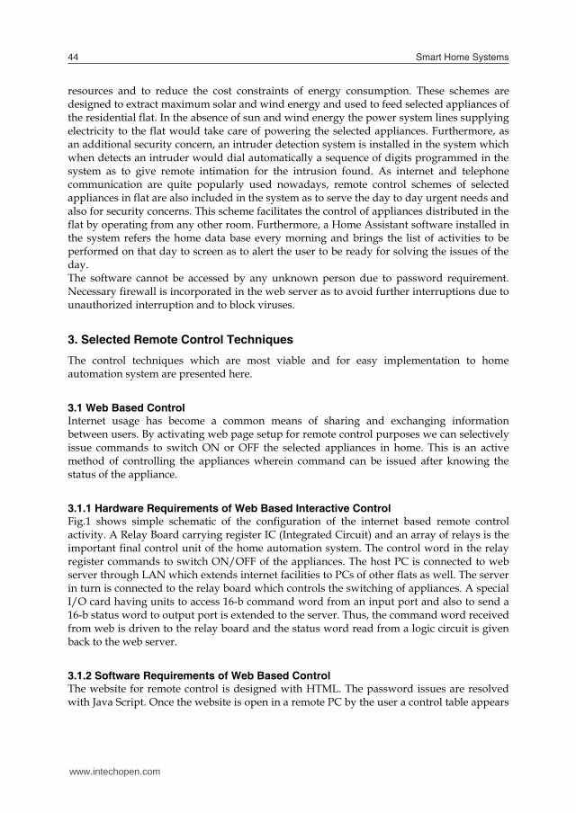
3.1.1 Hardware Requirements of Web Based Interactive Control Fig.1 shows simple schematic of the configuration of the internet based remote control activity. A Relay Board carrying register IC (Integrated Circuit) and an array of relays is the important final control unit of the home automation system. The control word in the relay register commands to switch ON/OFF of the appliances. The host PC is connected to web server through LAN which extends internet facilities to PCs of other flats as well. The server in turn is connected to the relay board which controls the switching of appliances. A special I/O card having units to access 16-b command word from an input port and also to send a 16-b status word to output port is extended to the server. Thus, the command word received from web is driven to the relay board and the status word read from a logic circuit is given back to the web server.
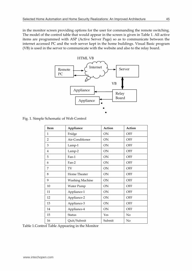
3.1.2 Software Requirements of Web Based Control The website for remote control is designed with HTML. The password issues are resolved with Java Script. Once the website is open in a remote PC by the user a control table appears
in the monitor screen providing options for the user for commanding the remote switching. The model of the control table that would appear in the screen is given in Table 1. All active items are programmed with ASP (Active Server Page) so as to communicate between the internet accessed PC and the web server kept in the home buildings. Visual Basic program (VB) is used in the server to communicate with the website and also to the relay board.
Fig. 1. Simple Schematic of Web Control
Item Appliance Action Action
1 Fridge ON OFF
2 Air-Conditioner ON OFF
3 Lamp-1 ON OFF
4 Lamp-2 ON OFF
5 Fan-1 ON OFF
6 Fan-2 ON OFF
7 TV ON OFF
8 Home Theater ON OFF
9 Washing Machine ON OFF
10 Water Pump ON OFF
11 Appliance-1 ON OFF
12 Appliance-2 ON OFF
13 Appliance-3 ON OFF
14 Appliance-4 ON OFF
15 Status Yes No
16 Quit/Submit Submit No Table 1.Control Table Appearing in the Monitor
Remote PC
Internet Server
Relay Board
Appliance
Appliance
HTML VB
VB
www.intechopen.com
Selected Home Automation and Home Security Realizations: An Improved Architecture 45
resources and to reduce the cost constraints of energy consumption. These schemes are designed to extract maximum solar and wind energy and used to feed selected appliances of the residential flat. In the absence of sun and wind energy the power system lines supplying electricity to the flat would take care of powering the selected appliances. Furthermore, as an additional security concern, an intruder detection system is installed in the system which when detects an intruder would dial automatically a sequence of digits programmed in the system as to give remote intimation for the intrusion found. As internet and telephone communication are quite popularly used nowadays, remote control schemes of selected appliances in flat are also included in the system as to serve the day to day urgent needs and also for security concerns. This scheme facilitates the control of appliances distributed in the flat by operating from any other room. Furthermore, a Home Assistant software installed in the system refers the home data base every morning and brings the list of activities to be performed on that day to screen as to alert the user to be ready for solving the issues of the day. The software cannot be accessed by any unknown person due to password requirement. Necessary firewall is incorporated in the web server as to avoid further interruptions due to unauthorized interruption and to block viruses.
3. Selected Remote Control Techniques
The control techniques which are most viable and for easy implementation to home automation system are presented here.
3.1 Web Based Control Internet usage has become a common means of sharing and exchanging information between users. By activating web page setup for remote control purposes we can selectively issue commands to switch ON or OFF the selected appliances in home. This is an active method of controlling the appliances wherein command can be issued after knowing the status of the appliance.
3.1.1 Hardware Requirements of Web Based Interactive Control Fig.1 shows simple schematic of the configuration of the internet based remote control activity. A Relay Board carrying register IC (Integrated Circuit) and an array of relays is the important final control unit of the home automation system. The control word in the relay register commands to switch ON/OFF of the appliances. The host PC is connected to web server through LAN which extends internet facilities to PCs of other flats as well. The server in turn is connected to the relay board which controls the switching of appliances. A special I/O card having units to access 16-b command word from an input port and also to send a 16-b status word to output port is extended to the server. Thus, the command word received from web is driven to the relay board and the status word read from a logic circuit is given back to the web server.
3.1.2 Software Requirements of Web Based Control The website for remote control is designed with HTML. The password issues are resolved with Java Script. Once the website is open in a remote PC by the user a control table appears
in the monitor screen providing options for the user for commanding the remote switching. The model of the control table that would appear in the screen is given in Table 1. All active items are programmed with ASP (Active Server Page) so as to communicate between the internet accessed PC and the web server kept in the home buildings. Visual Basic program (VB) is used in the server to communicate with the website and also to the relay board.
Fig. 1. Simple Schematic of Web Control
Item Appliance Action Action
1 Fridge ON OFF
2 Air-Conditioner ON OFF
3 Lamp-1 ON OFF
4 Lamp-2 ON OFF
5 Fan-1 ON OFF
6 Fan-2 ON OFF
7 TV ON OFF
8 Home Theater ON OFF
9 Washing Machine ON OFF
10 Water Pump ON OFF
11 Appliance-1 ON OFF
12 Appliance-2 ON OFF
13 Appliance-3 ON OFF
14 Appliance-4 ON OFF
15 Status Yes No
16 Quit/Submit Submit No Table 1.Control Table Appearing in the Monitor
Remote PC
Internet Server
Relay Board
Appliance
Appliance
HTML VB
VB
www.intechopen.com
Smart Home Systems46
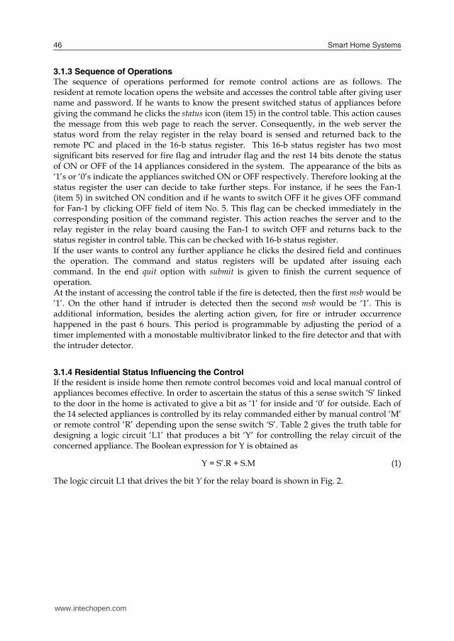
3.1.3 Sequence of Operations The sequence of operations performed for remote control actions are as follows. The resident at remote location opens the website and accesses the control table after giving user name and password. If he wants to know the present switched status of appliances before giving the command he clicks the status icon (item 15) in the control table. This action causes the message from this web page to reach the server. Consequently, in the web server the status word from the relay register in the relay board is sensed and returned back to the remote PC and placed in the 16-b status register. This 16-b status register has two most significant bits reserved for fire flag and intruder flag and the rest 14 bits denote the status of ON or OFF of the 14 appliances considered in the system. The appearance of the bits as ‘1’s or ‘0’s indicate the appliances switched ON or OFF respectively. Therefore looking at the status register the user can decide to take further steps. For instance, if he sees the Fan-1 (item 5) in switched ON condition and if he wants to switch OFF it he gives OFF command for Fan-1 by clicking OFF field of item No. 5. This flag can be checked immediately in the corresponding position of the command register. This action reaches the server and to the relay register in the relay board causing the Fan-1 to switch OFF and returns back to the status register in control table. This can be checked with 16-b status register. If the user wants to control any further appliance he clicks the desired field and continues the operation. The command and status registers will be updated after issuing each command. In the end quit option with submit is given to finish the current sequence of operation. At the instant of accessing the control table if the fire is detected, then the first msb would be ‘1’. On the other hand if intruder is detected then the second msb would be ‘1’. This is additional information, besides the alerting action given, for fire or intruder occurrence happened in the past 6 hours. This period is programmable by adjusting the period of a timer implemented with a monostable multivibrator linked to the fire detector and that with the intruder detector.
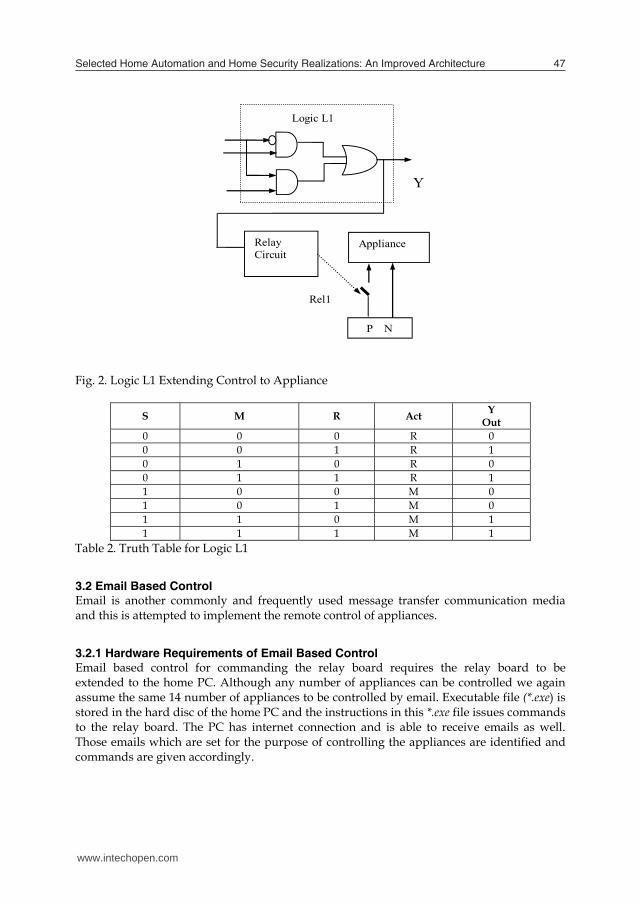
3.1.4 Residential Status Influencing the Control If the resident is inside home then remote control becomes void and local manual control of appliances becomes effective. In order to ascertain the status of this a sense switch ‘S’ linked to the door in the home is activated to give a bit as ‘1’ for inside and ‘0’ for outside. Each of the 14 selected appliances is controlled by its relay commanded either by manual control ‘M’ or remote control ‘R’ depending upon the sense switch ‘S’. Table 2 gives the truth table for designing a logic circuit ‘L1’ that produces a bit ‘Y’ for controlling the relay circuit of the concerned appliance. The Boolean expression for Y is obtained as
Y = S’.R + S.M (1)
The logic circuit L1 that drives the bit Y for the relay board is shown in Fig. 2.
Fig. 2. Logic L1 Extending Control to Appliance
S M R Act Y Out
0 0 0 R 0 0 0 1 R 1 0 1 0 R 0 0 1 1 R 1 1 0 0 M 0 1 0 1 M 0 1 1 0 M 1 1 1 1 M 1
Table 2. Truth Table for Logic L1
3.2 Email Based Control Email is another commonly and frequently used message transfer communication media and this is attempted to implement the remote control of appliances.
3.2.1 Hardware Requirements of Email Based Control Email based control for commanding the relay board requires the relay board to be extended to the home PC. Although any number of appliances can be controlled we again assume the same 14 number of appliances to be controlled by email. Executable file (*.exe) is stored in the hard disc of the home PC and the instructions in this *.exe file issues commands to the relay board. The PC has internet connection and is able to receive emails as well. Those emails which are set for the purpose of controlling the appliances are identified and commands are given accordingly.
Y
Relay Circuit
Appliance
P N
Rel1
Logic L1
www.intechopen.com
Selected Home Automation and Home Security Realizations: An Improved Architecture 47
3.1.3 Sequence of Operations The sequence of operations performed for remote control actions are as follows. The resident at remote location opens the website and accesses the control table after giving user name and password. If he wants to know the present switched status of appliances before giving the command he clicks the status icon (item 15) in the control table. This action causes the message from this web page to reach the server. Consequently, in the web server the status word from the relay register in the relay board is sensed and returned back to the remote PC and placed in the 16-b status register. This 16-b status register has two most significant bits reserved for fire flag and intruder flag and the rest 14 bits denote the status of ON or OFF of the 14 appliances considered in the system. The appearance of the bits as ‘1’s or ‘0’s indicate the appliances switched ON or OFF respectively. Therefore looking at the status register the user can decide to take further steps. For instance, if he sees the Fan-1 (item 5) in switched ON condition and if he wants to switch OFF it he gives OFF command for Fan-1 by clicking OFF field of item No. 5. This flag can be checked immediately in the corresponding position of the command register. This action reaches the server and to the relay register in the relay board causing the Fan-1 to switch OFF and returns back to the status register in control table. This can be checked with 16-b status register. If the user wants to control any further appliance he clicks the desired field and continues the operation. The command and status registers will be updated after issuing each command. In the end quit option with submit is given to finish the current sequence of operation. At the instant of accessing the control table if the fire is detected, then the first msb would be ‘1’. On the other hand if intruder is detected then the second msb would be ‘1’. This is additional information, besides the alerting action given, for fire or intruder occurrence happened in the past 6 hours. This period is programmable by adjusting the period of a timer implemented with a monostable multivibrator linked to the fire detector and that with the intruder detector.
3.1.4 Residential Status Influencing the Control If the resident is inside home then remote control becomes void and local manual control of appliances becomes effective. In order to ascertain the status of this a sense switch ‘S’ linked to the door in the home is activated to give a bit as ‘1’ for inside and ‘0’ for outside. Each of the 14 selected appliances is controlled by its relay commanded either by manual control ‘M’ or remote control ‘R’ depending upon the sense switch ‘S’. Table 2 gives the truth table for designing a logic circuit ‘L1’ that produces a bit ‘Y’ for controlling the relay circuit of the concerned appliance. The Boolean expression for Y is obtained as
Y = S’.R + S.M (1)
The logic circuit L1 that drives the bit Y for the relay board is shown in Fig. 2.
Fig. 2. Logic L1 Extending Control to Appliance
S M R Act Y Out
0 0 0 R 0 0 0 1 R 1 0 1 0 R 0 0 1 1 R 1 1 0 0 M 0 1 0 1 M 0 1 1 0 M 1 1 1 1 M 1
Table 2. Truth Table for Logic L1
3.2 Email Based Control Email is another commonly and frequently used message transfer communication media and this is attempted to implement the remote control of appliances.
3.2.1 Hardware Requirements of Email Based Control Email based control for commanding the relay board requires the relay board to be extended to the home PC. Although any number of appliances can be controlled we again assume the same 14 number of appliances to be controlled by email. Executable file (*.exe) is stored in the hard disc of the home PC and the instructions in this *.exe file issues commands to the relay board. The PC has internet connection and is able to receive emails as well. Those emails which are set for the purpose of controlling the appliances are identified and commands are given accordingly.
Y
Relay Circuit
Appliance
P N
Rel1
Logic L1
www.intechopen.com
Smart Home Systems48
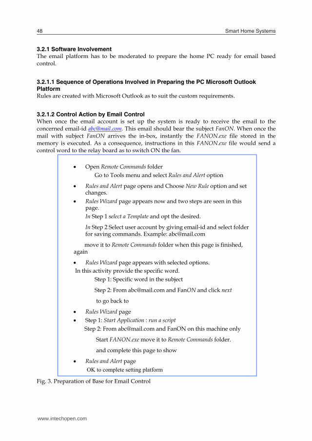
3.2.1 Software Involvement The email platform has to be moderated to prepare the home PC ready for email based control.
3.2.1.1 Sequence of Operations Involved in Preparing the PC Microsoft Outlook Platform Rules are created with Microsoft Outlook as to suit the custom requirements.
3.2.1.2 Control Action by Email Control When once the email account is set up the system is ready to receive the email to the concerned email-id [email protected]. This email should bear the subject FanON. When once the mail with subject FanON arrives the in-box, instantly the FANON.exe file stored in the memory is executed. As a consequence, instructions in this FANON.exe file would send a control word to the relay board as to switch ON the fan.
Fig. 3. Preparation of Base for Email Control
Open Remote Commands folder
Go to Tools menu and select Rules and Alert option
Rules and Alert page opens and Choose New Rule option and set changes.
Rules Wizard page appears now and two steps are seen in this page. In Step 1 select a Template and opt the desired.
In Step 2 Select user account by giving email-id and select folder for saving commands. Example: [email protected]
move it to Remote Commands folder when this page is finished, again
Rules Wizard page appears with selected options. In this activity provide the specific word.
Step 1: Specific word in the subject
Step 2: From [email protected] and FanON and click next
to go back to
Rules Wizard page Step 1: Start Application : run a script
Step 2: From [email protected] and FanON on this machine only
Start FANON.exe move it to Remote Commands folder.
and complete this page to show
Rules and Alert page OK to complete setting platform
3.3 SMS based Control Sending text messages to a cellular phone from other cellular phone has also become a common practice nowadays. This method of communication depends on the cellular telecommunication network. We now use this facility for controlling the remote home appliances by SMS sent from a cellular phone.
3.3.1 Hardware and Setup requirements of SMS based Control Several cell phones have connection ports to enable them to interface with PC or other equipments (Mobile telephone directory, 2009) for transferring files from phone to its peripherals. Using this feature we now use a decoder to the port for converting the digit received from SMS as a drive code for the register in the relay board. Whatever may be communication medium of issuing commands to the appliances the final control elements are the relays stacked in relay board. Fig.4 shows a simple schematic of the SMS based control system. The user sends SMS message to control an appliance in the flat from another cell phone. For instance he wants to switch ON Fan-1, as indicated in the control table of Table 1. As the code for Fan-1 being ‘5’ he sends an SMS from a cell of known number 123456 {say} to the home cell phone just the code ‘5 ON’. This digit as the text message reaches the cell phone and is saved in in-box. The sending mobile number 123456 also is saved. A software adjustment is made in the mobile system phone that if the message arrives from the mobile of No. 123456 then after identifying the digit received the digit ‘5’ (0101) is sent together with ‘1’, for ON command, to the output port. This makes the ON/OFF’ flag be ‘1’ for ON action to be commanded. The decoder decodes the command 5 (0101) into {0000000000010000} and provides the drive control bit ‘1’ for {ON/OFF’} selecting the appliance in 5th position for ON action. Consequently the relay circuit of Fan-1 would be switched ON irrespective of what the status it was before.
Fig. 4. Simple Schematic of SMS Based Control
3.3.2 Relay Register Circuit The relay register needs to retain the flags (control bits) of the other appliances while changing the flag of the present command. This is realized by the circuit shown in Fig. 5.
Cell phone
Port Decoder
Relay Board
Appliances
Logic
www.intechopen.com

Selected Home Automation and Home Security Realizations: An Improved Architecture 49
3.2.1 Software Involvement The email platform has to be moderated to prepare the home PC ready for email based control.
3.2.1.1 Sequence of Operations Involved in Preparing the PC Microsoft Outlook Platform Rules are created with Microsoft Outlook as to suit the custom requirements.
3.2.1.2 Control Action by Email Control When once the email account is set up the system is ready to receive the email to the concerned email-id [email protected]. This email should bear the subject FanON. When once the mail with subject FanON arrives the in-box, instantly the FANON.exe file stored in the memory is executed. As a consequence, instructions in this FANON.exe file would send a control word to the relay board as to switch ON the fan.
Fig. 3. Preparation of Base for Email Control
Open Remote Commands folder
Go to Tools menu and select Rules and Alert option
Rules and Alert page opens and Choose New Rule option and set changes.
Rules Wizard page appears now and two steps are seen in this page. In Step 1 select a Template and opt the desired.
In Step 2 Select user account by giving email-id and select folder for saving commands. Example: [email protected]
move it to Remote Commands folder when this page is finished, again
Rules Wizard page appears with selected options. In this activity provide the specific word.
Step 1: Specific word in the subject
Step 2: From [email protected] and FanON and click next
to go back to
Rules Wizard page Step 1: Start Application : run a script
Step 2: From [email protected] and FanON on this machine only
Start FANON.exe move it to Remote Commands folder.
and complete this page to show
Rules and Alert page OK to complete setting platform
3.3 SMS based Control Sending text messages to a cellular phone from other cellular phone has also become a common practice nowadays. This method of communication depends on the cellular telecommunication network. We now use this facility for controlling the remote home appliances by SMS sent from a cellular phone.
3.3.1 Hardware and Setup requirements of SMS based Control Several cell phones have connection ports to enable them to interface with PC or other equipments (Mobile telephone directory, 2009) for transferring files from phone to its peripherals. Using this feature we now use a decoder to the port for converting the digit received from SMS as a drive code for the register in the relay board. Whatever may be communication medium of issuing commands to the appliances the final control elements are the relays stacked in relay board. Fig.4 shows a simple schematic of the SMS based control system. The user sends SMS message to control an appliance in the flat from another cell phone. For instance he wants to switch ON Fan-1, as indicated in the control table of Table 1. As the code for Fan-1 being ‘5’ he sends an SMS from a cell of known number 123456 {say} to the home cell phone just the code ‘5 ON’. This digit as the text message reaches the cell phone and is saved in in-box. The sending mobile number 123456 also is saved. A software adjustment is made in the mobile system phone that if the message arrives from the mobile of No. 123456 then after identifying the digit received the digit ‘5’ (0101) is sent together with ‘1’, for ON command, to the output port. This makes the ON/OFF’ flag be ‘1’ for ON action to be commanded. The decoder decodes the command 5 (0101) into {0000000000010000} and provides the drive control bit ‘1’ for {ON/OFF’} selecting the appliance in 5th position for ON action. Consequently the relay circuit of Fan-1 would be switched ON irrespective of what the status it was before.
Fig. 4. Simple Schematic of SMS Based Control
3.3.2 Relay Register Circuit The relay register needs to retain the flags (control bits) of the other appliances while changing the flag of the present command. This is realized by the circuit shown in Fig. 5.
Cell phone
Port Decoder
Relay Board
Appliances
Logic
www.intechopen.com

Smart Home Systems50
The JK Flip flops working as flag bits of the relay register has asynchronous bits Preset (PR’) and Clear (CLR’) and the command is exerted through them. The figure shows only flip flop. The Enable bit (En) arrives from the decoded appliance code and the ON/OFF’ bit arrives due to action code. For instance if the 5th appliance is commanded then En bit of the 5th flip flop becomes ‘1’ and if ON command arrives ON/OFF’ bit becomes ‘1’ causing PR’ to ‘0’ as to set the flip flop (‘1’). Obviously if ON/OFF’ is ‘0’ then flip flop would be cleared.
Fig. 5. Updating the bit of Relay Register
Fig. 6. Telephonic Control of appliances
Ring Detector
Gyrator
Control Bridge
Ringe
Transceiver
Cradle
Relay
Appliances
J Q
K Q’
En
ON/OFF’En
PR’
CLR’
3.3 Telephonic Method of Control Landline telephony has been serving as the major communication media used for tele-conversation. Although the launching of cellular telephony and the internet based voice communication has reduced its usage, landline telephonic network still enjoys its service due to its simplicity and cost effectiveness offered to subscribers. Using landline telephone controls were issued (Balasubramanian, 2003) by dialing additional digits for switching ON or OFF of the electrical appliances in home. An extension card attached to the home telephone identifies the digit, decodes it and controls switching the appliances. Its principle is outlined in Fig.6. In order to control switching the appliances in home the user dials the digits of home telephone. This gives ring in home telephone. The extension card attached to it counts the ring cycles and actuates a relay to close the cradle contacts despite the handset unmoved from cradle. The closing of contacts extends a gyrator and control bridge across the lines simulating the condition of establishing connection to home set. The additional digit dialed is decoded and the corresponding appliance is switched ON/OFF by the relay circuit.
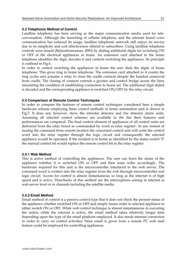
3.4 Comparison of Remote Control Techniques In order to compare the features of remote control techniques considered here a simple hardware scheme employing these control methods in home automation unit is shown in Fig.7. It does not, however, show the intruder detector and fire detector alarm units. Assuming all selected control schemes are available in the flat their features and performances are compared. The final control element of appliances of all control units are delivered from the relay board as commanded by word in relay register. At any instant of issuing the command from remote location the concerned control unit will write the control word into the relay register through the logic circuit and consequently the selected appliance would be operated. If the resident is in home as identified by the status switch ‘S’ the manual control bit would replace the remote control bit in the relay register.
3.4.1 Web Method This is active method of controlling the appliances. The user can learn the status of the appliance whether it is switched ON or OFF and then issue order accordingly. The hardware required for this unit is the microcontroller interfaced to the web server. The command word is written into the relay register from the web through microcontroller and logic circuit. Access for control is almost instantaneous so long as the internet is of high speed and is active. Drawbacks of this method are the interruptions arising in internet at web server level or in channels including the satellite media.
3.4.2 Email Method Email method of control is a passive control type that it does not check the present status of the appliance whether switched ON or OFF and simply issues order to selected appliance to either switch ON or OFF. While web control technique is almost instantaneous in executing the orders while the internet is active, the email method takes relatively longer time depending upon the type of the email platform employed. It also needs internet connection in order to carry on control activities. Since email is given from a remote PC web mail feature could be employed for controlling appliances.
www.intechopen.com
Selected Home Automation and Home Security Realizations: An Improved Architecture 51
The JK Flip flops working as flag bits of the relay register has asynchronous bits Preset (PR’) and Clear (CLR’) and the command is exerted through them. The figure shows only flip flop. The Enable bit (En) arrives from the decoded appliance code and the ON/OFF’ bit arrives due to action code. For instance if the 5th appliance is commanded then En bit of the 5th flip flop becomes ‘1’ and if ON command arrives ON/OFF’ bit becomes ‘1’ causing PR’ to ‘0’ as to set the flip flop (‘1’). Obviously if ON/OFF’ is ‘0’ then flip flop would be cleared.
Fig. 5. Updating the bit of Relay Register
Fig. 6. Telephonic Control of appliances
Ring Detector
Gyrator
Control Bridge
Ringe
Transceiver
Cradle
Relay
Appliances
J Q
K Q’
En
ON/OFF’En
PR’
CLR’
3.3 Telephonic Method of Control Landline telephony has been serving as the major communication media used for tele-conversation. Although the launching of cellular telephony and the internet based voice communication has reduced its usage, landline telephonic network still enjoys its service due to its simplicity and cost effectiveness offered to subscribers. Using landline telephone controls were issued (Balasubramanian, 2003) by dialing additional digits for switching ON or OFF of the electrical appliances in home. An extension card attached to the home telephone identifies the digit, decodes it and controls switching the appliances. Its principle is outlined in Fig.6. In order to control switching the appliances in home the user dials the digits of home telephone. This gives ring in home telephone. The extension card attached to it counts the ring cycles and actuates a relay to close the cradle contacts despite the handset unmoved from cradle. The closing of contacts extends a gyrator and control bridge across the lines simulating the condition of establishing connection to home set. The additional digit dialed is decoded and the corresponding appliance is switched ON/OFF by the relay circuit.
3.4 Comparison of Remote Control Techniques In order to compare the features of remote control techniques considered here a simple hardware scheme employing these control methods in home automation unit is shown in Fig.7. It does not, however, show the intruder detector and fire detector alarm units. Assuming all selected control schemes are available in the flat their features and performances are compared. The final control element of appliances of all control units are delivered from the relay board as commanded by word in relay register. At any instant of issuing the command from remote location the concerned control unit will write the control word into the relay register through the logic circuit and consequently the selected appliance would be operated. If the resident is in home as identified by the status switch ‘S’ the manual control bit would replace the remote control bit in the relay register.
3.4.1 Web Method This is active method of controlling the appliances. The user can learn the status of the appliance whether it is switched ON or OFF and then issue order accordingly. The hardware required for this unit is the microcontroller interfaced to the web server. The command word is written into the relay register from the web through microcontroller and logic circuit. Access for control is almost instantaneous so long as the internet is of high speed and is active. Drawbacks of this method are the interruptions arising in internet at web server level or in channels including the satellite media.
3.4.2 Email Method Email method of control is a passive control type that it does not check the present status of the appliance whether switched ON or OFF and simply issues order to selected appliance to either switch ON or OFF. While web control technique is almost instantaneous in executing the orders while the internet is active, the email method takes relatively longer time depending upon the type of the email platform employed. It also needs internet connection in order to carry on control activities. Since email is given from a remote PC web mail feature could be employed for controlling appliances.
www.intechopen.com
Smart Home Systems52
3.4.3 SMS Control Since cellular network is independent from internet and landline telephone network it needs just cellular phone for passing the control digits to the relay register. Neither PC nor its connection to internet is needed for control through SMS. From remote mobile phone an SMS need be sent to the home mobile phone for effecting the control of the appliance. The hardware requirement is therefore simpler than other methods of control.
3.4.4 Telephone Dialling Landline telephone dialing is another simple method of control. Here the landline telephone is attached with an extension card and kept in home such that when the control digit is dialed from external phone it is identified and passed to the relay register for effecting the control. This control unit is simple and is involved in telephone loop independent of the internet connectivity. Unlike web based control there is no facility to check the status of the appliance before commanding the control.
Fig. 7. Selected Remote Control Schemes Installed in Home
3.4.5 Further Discussions Only remote control aspect of home automation system is considered here for its betterment and easy implementation. Essential schemes for remote control of appliances are proposed here and depending upon the circumstances and requirements one or more of the schemes
Telephone Equipment
PC
Commn Terminal
Logic L1
Relay
Reg
Relay Board
Appliances
Web Server
To other flats
Micro-controller
Extension Board
Cell Phone
I/O Interface
Trigger from PC, Web micro-controller Telephone extension board Cell phone I/O interface
Display
can be chosen for installation in a given system. Relay register and relay board unit is the essential hardware unit present in the home automation system where selected remote control schemes could control the bits in relay register. Whatever may the control technique used in the system the final control element would be the relay operating to switch ON or OFF of the selected appliance. Internet based control performed through web is versatile and interactive in controlling the appliances. If more and more appliances are needed to be controlled then an encoder is needed to be used in the transmitter to have the standard word length of 16-bits for the control word. In the receiver the 16-bit control word is decoded and the corresponding bits are taken to the relays for switching the appliances. In simple automation system where internet facilities are not provided one can opt cellular phone based control scheme which is simple and cost effective. Alternatively for such requirements landline telephone with an extension card could also be opted.
3.5 Personal Digital Assistant The personal Digital software is installed in PC which is linked to the operating system that brings the daily chart to the screen of the PC monitor. In the database accessible to the OS, the various activities to be done on different dates and times are pre-programmed and this updated daily by the user. The personal digital software refers the home data base every morning at the set time and brings the list of activities to be done on that day to screen as to alert the user to be ready for solving the issues of the day.
4. Home Security Concerns
An important home security aspect insists that the fire accident that can happen in home during the absence of the resident should be alerted and intimated to a remote location. Also intruder making unauthorized entry into the flat should also be informed to a remote location for taking follow up actions. Authorized visitor entry supported by video image presentation is another aspect which helps in security concerns.
4.1 Fire and Intruder Alert
4.1.1 Fire Detection and Intimation The occurrence fire in home is detected electronically. It is then sent as SMS and then converted into email and sent again to a remote PC. The arrival of email in remote PC executes a file to create an alarming sound. The email can also be received in a cell phone causing a beep sound. Also the detection of intruder by a sensor sends another SMS which is converted into email as to make appropriate indication in remote PC or in cell phone.
4.1.1.1 System Overview A simple scheme sending SMS upon fire detection or intruder detection and then its email conversion is shown in Fig.8. An 8085 based microprocessor system is extended to light and heat sensors through interrupt interface. Through I/O ports of the microcomputer a GSM module is connected. The GSM module is backed up with the facilities of TynTec system (Tyntec website, 2009). If excessive light or heat is sensed electronically in the flat and if any of its voltage exceeds the threshold then it interrupts the microcomputer (RST7.5). The
www.intechopen.com
Selected Home Automation and Home Security Realizations: An Improved Architecture 53
3.4.3 SMS Control Since cellular network is independent from internet and landline telephone network it needs just cellular phone for passing the control digits to the relay register. Neither PC nor its connection to internet is needed for control through SMS. From remote mobile phone an SMS need be sent to the home mobile phone for effecting the control of the appliance. The hardware requirement is therefore simpler than other methods of control.
3.4.4 Telephone Dialling Landline telephone dialing is another simple method of control. Here the landline telephone is attached with an extension card and kept in home such that when the control digit is dialed from external phone it is identified and passed to the relay register for effecting the control. This control unit is simple and is involved in telephone loop independent of the internet connectivity. Unlike web based control there is no facility to check the status of the appliance before commanding the control.
Fig. 7. Selected Remote Control Schemes Installed in Home
3.4.5 Further Discussions Only remote control aspect of home automation system is considered here for its betterment and easy implementation. Essential schemes for remote control of appliances are proposed here and depending upon the circumstances and requirements one or more of the schemes
Telephone Equipment
PC
Commn Terminal
Logic L1
Relay
Reg
Relay Board
Appliances
Web Server
To other flats
Micro-controller
Extension Board
Cell Phone
I/O Interface
Trigger from PC, Web micro-controller Telephone extension board Cell phone I/O interface
Display
can be chosen for installation in a given system. Relay register and relay board unit is the essential hardware unit present in the home automation system where selected remote control schemes could control the bits in relay register. Whatever may the control technique used in the system the final control element would be the relay operating to switch ON or OFF of the selected appliance. Internet based control performed through web is versatile and interactive in controlling the appliances. If more and more appliances are needed to be controlled then an encoder is needed to be used in the transmitter to have the standard word length of 16-bits for the control word. In the receiver the 16-bit control word is decoded and the corresponding bits are taken to the relays for switching the appliances. In simple automation system where internet facilities are not provided one can opt cellular phone based control scheme which is simple and cost effective. Alternatively for such requirements landline telephone with an extension card could also be opted.
3.5 Personal Digital Assistant The personal Digital software is installed in PC which is linked to the operating system that brings the daily chart to the screen of the PC monitor. In the database accessible to the OS, the various activities to be done on different dates and times are pre-programmed and this updated daily by the user. The personal digital software refers the home data base every morning at the set time and brings the list of activities to be done on that day to screen as to alert the user to be ready for solving the issues of the day.
4. Home Security Concerns
An important home security aspect insists that the fire accident that can happen in home during the absence of the resident should be alerted and intimated to a remote location. Also intruder making unauthorized entry into the flat should also be informed to a remote location for taking follow up actions. Authorized visitor entry supported by video image presentation is another aspect which helps in security concerns.
4.1 Fire and Intruder Alert
4.1.1 Fire Detection and Intimation The occurrence fire in home is detected electronically. It is then sent as SMS and then converted into email and sent again to a remote PC. The arrival of email in remote PC executes a file to create an alarming sound. The email can also be received in a cell phone causing a beep sound. Also the detection of intruder by a sensor sends another SMS which is converted into email as to make appropriate indication in remote PC or in cell phone.
4.1.1.1 System Overview A simple scheme sending SMS upon fire detection or intruder detection and then its email conversion is shown in Fig.8. An 8085 based microprocessor system is extended to light and heat sensors through interrupt interface. Through I/O ports of the microcomputer a GSM module is connected. The GSM module is backed up with the facilities of TynTec system (Tyntec website, 2009). If excessive light or heat is sensed electronically in the flat and if any of its voltage exceeds the threshold then it interrupts the microcomputer (RST7.5). The
www.intechopen.com

Smart Home Systems54
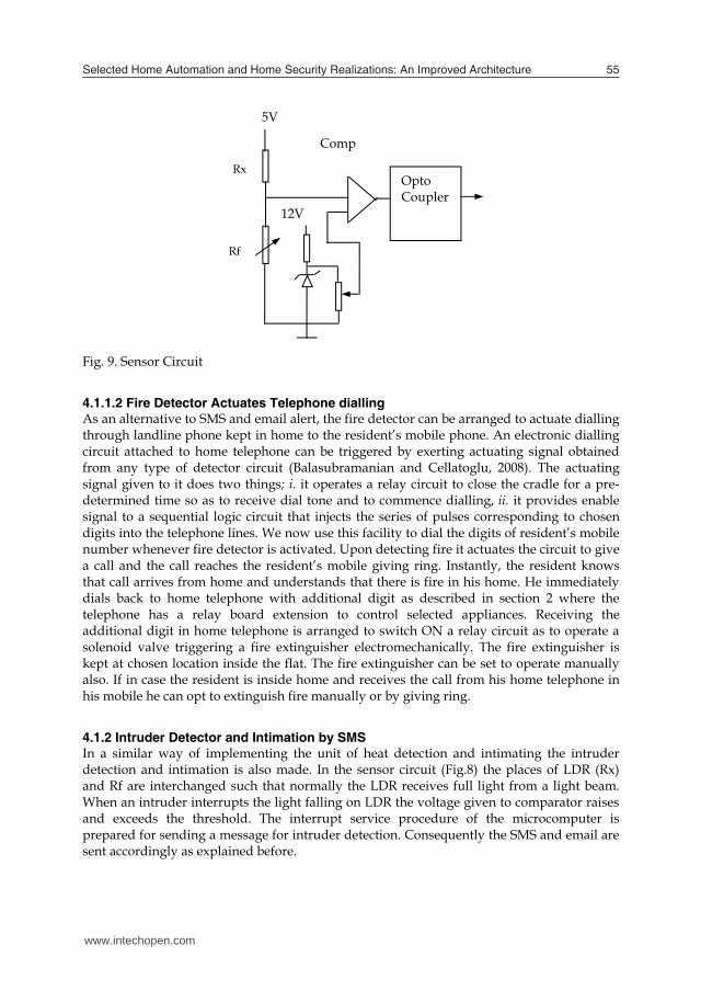
interrupt service subroutine is arranged to send a text message to GSM module which in turn sends an email to the number provided by TynTec. The two way SMS online tool of the TynTec converts the SMS into an email and forwards to the specified email-id. This email message can be received in an internet backed PC. As described before the email platform is set up with a rule such that as soon as the email arrives with a specific word in the text the exe file would run a set of instructions as to give alarming message. The email can also be received in a cell phone causing beep sound alerting the user. The detection of intruder interrupts the microprocessor on the interrupt line RST6.5. The interrupt service subroutine of RST6.5 sends the related message to GSM module and this in turn sends the email to the concerned email-id. The detection of fire is made by sensing the exhaustive heat or light electronically and comparing with a threshold. The sensor circuit is shown in Fig.9. In place of Rx, LDR is used for light sensing and thermistor is used for heat sensing. These sensitive elements are kept at selected spots in the home. Rx might be a single element or an array of elements where all elements representing Rx are connected in parallel to the sensor circuit. If anyone becomes active it pulls down the effective resistance of Rx resulting in increased voltage to the comparator.
Fig. 8. Simple Schematic of Alarming by Fire and Intruder Detection
Light Detector
Heat Detector
Micro controller
Interrupts
Port
Tx Rx GSM Module
RST7.5
RST6.5
Intruder Detector
Fig. 9. Sensor Circuit
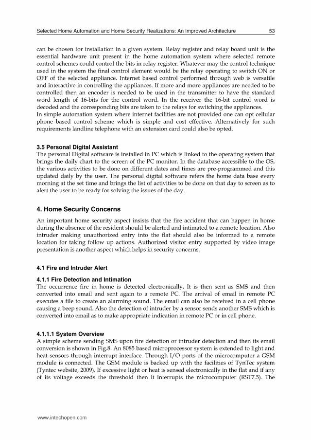
4.1.1.2 Fire Detector Actuates Telephone dialling As an alternative to SMS and email alert, the fire detector can be arranged to actuate dialling through landline phone kept in home to the resident’s mobile phone. An electronic dialling circuit attached to home telephone can be triggered by exerting actuating signal obtained from any type of detector circuit (Balasubramanian and Cellatoglu, 2008). The actuating signal given to it does two things; i. it operates a relay circuit to close the cradle for a pre-determined time so as to receive dial tone and to commence dialling, ii. it provides enable signal to a sequential logic circuit that injects the series of pulses corresponding to chosen digits into the telephone lines. We now use this facility to dial the digits of resident’s mobile number whenever fire detector is activated. Upon detecting fire it actuates the circuit to give a call and the call reaches the resident’s mobile giving ring. Instantly, the resident knows that call arrives from home and understands that there is fire in his home. He immediately dials back to home telephone with additional digit as described in section 2 where the telephone has a relay board extension to control selected appliances. Receiving the additional digit in home telephone is arranged to switch ON a relay circuit as to operate a solenoid valve triggering a fire extinguisher electromechanically. The fire extinguisher is kept at chosen location inside the flat. The fire extinguisher can be set to operate manually also. If in case the resident is inside home and receives the call from his home telephone in his mobile he can opt to extinguish fire manually or by giving ring.
4.1.2 Intruder Detector and Intimation by SMS In a similar way of implementing the unit of heat detection and intimating the intruder detection and intimation is also made. In the sensor circuit (Fig.8) the places of LDR (Rx) and Rf are interchanged such that normally the LDR receives full light from a light beam. When an intruder interrupts the light falling on LDR the voltage given to comparator raises and exceeds the threshold. The interrupt service procedure of the microcomputer is prepared for sending a message for intruder detection. Consequently the SMS and email are sent accordingly as explained before.
12V
Comp
Opto Coupler
Rx
Rf
5V
www.intechopen.com
Selected Home Automation and Home Security Realizations: An Improved Architecture 55
interrupt service subroutine is arranged to send a text message to GSM module which in turn sends an email to the number provided by TynTec. The two way SMS online tool of the TynTec converts the SMS into an email and forwards to the specified email-id. This email message can be received in an internet backed PC. As described before the email platform is set up with a rule such that as soon as the email arrives with a specific word in the text the exe file would run a set of instructions as to give alarming message. The email can also be received in a cell phone causing beep sound alerting the user. The detection of intruder interrupts the microprocessor on the interrupt line RST6.5. The interrupt service subroutine of RST6.5 sends the related message to GSM module and this in turn sends the email to the concerned email-id. The detection of fire is made by sensing the exhaustive heat or light electronically and comparing with a threshold. The sensor circuit is shown in Fig.9. In place of Rx, LDR is used for light sensing and thermistor is used for heat sensing. These sensitive elements are kept at selected spots in the home. Rx might be a single element or an array of elements where all elements representing Rx are connected in parallel to the sensor circuit. If anyone becomes active it pulls down the effective resistance of Rx resulting in increased voltage to the comparator.
Fig. 8. Simple Schematic of Alarming by Fire and Intruder Detection
Light Detector
Heat Detector
Micro controller
Interrupts
Port
Tx Rx GSM Module
RST7.5
RST6.5
Intruder Detector
Fig. 9. Sensor Circuit
4.1.1.2 Fire Detector Actuates Telephone dialling As an alternative to SMS and email alert, the fire detector can be arranged to actuate dialling through landline phone kept in home to the resident’s mobile phone. An electronic dialling circuit attached to home telephone can be triggered by exerting actuating signal obtained from any type of detector circuit (Balasubramanian and Cellatoglu, 2008). The actuating signal given to it does two things; i. it operates a relay circuit to close the cradle for a pre-determined time so as to receive dial tone and to commence dialling, ii. it provides enable signal to a sequential logic circuit that injects the series of pulses corresponding to chosen digits into the telephone lines. We now use this facility to dial the digits of resident’s mobile number whenever fire detector is activated. Upon detecting fire it actuates the circuit to give a call and the call reaches the resident’s mobile giving ring. Instantly, the resident knows that call arrives from home and understands that there is fire in his home. He immediately dials back to home telephone with additional digit as described in section 2 where the telephone has a relay board extension to control selected appliances. Receiving the additional digit in home telephone is arranged to switch ON a relay circuit as to operate a solenoid valve triggering a fire extinguisher electromechanically. The fire extinguisher is kept at chosen location inside the flat. The fire extinguisher can be set to operate manually also. If in case the resident is inside home and receives the call from his home telephone in his mobile he can opt to extinguish fire manually or by giving ring.
4.1.2 Intruder Detector and Intimation by SMS In a similar way of implementing the unit of heat detection and intimating the intruder detection and intimation is also made. In the sensor circuit (Fig.8) the places of LDR (Rx) and Rf are interchanged such that normally the LDR receives full light from a light beam. When an intruder interrupts the light falling on LDR the voltage given to comparator raises and exceeds the threshold. The interrupt service procedure of the microcomputer is prepared for sending a message for intruder detection. Consequently the SMS and email are sent accordingly as explained before.
12V
Comp
Opto Coupler
Rx
Rf
5V
www.intechopen.com
Smart Home Systems56
4.1.3 Updating Control Table Flags As mentioned already the two most significant bits of the status register will be updated by the fire detector and intruder detector as and when they get activated and the flags can be seen in the control table (Table 1). The flags will remain for 6 hours period and if desired it can be changed to any other desired value with the monostable multivibrator.
4.1.4 Discussion The intruder alert and fire alert given automatically to a remote location through SMS from mobile phone converted into email is a passive system passing the message to the concerned for taking counteractive measures. The message can be reached through landline phone as well. One counteractive measure would be to dial the additional digit to operate the fire extinguisher. On the other hand, the fire extinguisher could be included in the list of appliances for web control if desired. In this case the user can also see the status register to understand the present status of fire detector or intruder detector and take action through web control table itself. All these techniques presented here are expected to enhance the remote control and alerting features of home automation systems.
4.2 Regulating Visitor Entry The regulated visitor entry unit helps checking the visitor through video and admits the intended visitor to flat. A preliminary form of video door entry was reported in the past (Balasubramanian et al, 1999). We enhanced the performance of the system (Balasubramanian and Cellatoglu, 2008) in certain aspects and now more considerations are given. This regulated visitor entry unit has a register to record the visitor’s time and date. Maintaining time and displaying in monitor screen would be useful to the resident and also for recording in the visitor register.
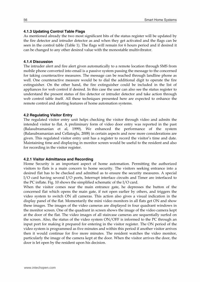
4.2.1 Visitor Admittance and Recording Home Security is an important aspect of home automation. Permitting the authorized visitors to flats is a main concern to home security. The visitors seeking entrance into a desired flat has to be checked and admitted as to ensure the security measures. A special I/O card having several I/O ports, Interrupt interface circuits and Timer are interfaced to the PC inflate. Fig. 10 shows the simplified schematic of the I/O card. When the visitor comes near the main entrance gate, he depresses the button of the concerned flat which opens the main gate, if not open earlier by others, and triggers the video system to switch ON all cameras. This action also gives a visual indication in the display panel of the flat. Momentarily the mini video monitors in all flats get ON and show these images. The images of the video cameras are displayed in four quadrant windows in the monitor screen. One of the quadrant in screen shows the image of the video camera kept at the door of the flat. The video images of all staircase cameras are sequentially surfed on the screen. Also, the status of the video system ON/OFF is informed to the PC through an input port for making it prepared for entering in the visitor register. The ON period of the video system is programmed as five minutes and within this period if another visitor arrives then it would continue for five more minutes. The resident watches the video monitor, particularly the image of the camera kept at the door. When the visitor arrives the door, the door is let open by the resident upon his decision.
Fig. 10. Simple Scheme of Visitor Admittance and Recording
4.2.2 Visitor Registor A file is organized in hard disc to have a record of the visitor with time and date taken from the time and date register. When the door is open by the resident this also gives an interrupt to open the visitor register and creates a new record. The new record in the file is automatically loaded with the serial number and the date and time fields. It is up to the resident to enter the name or identity of the visitor as a window slot that would appear on the screen for making entry. The opening of the door lock by anyone using the key does not activate the interrupt and hence no changes are made in the visitor file. This avoids recording the resident himself as visitor each time when he enters to the flat. The file can be viewed by the resident at any desired instant of time when needed.
4.2.3 Time and Date Register As in the past (Balasubramanian, 1991) a digital clock is maintained by the PC by organizing software counters for seconds, minutes and hours. RAM memory locations in PC are organized as software counters. The timer of the I/O card (Fig.10) produces pulse train at the rate of 1 Hz and this is used to interrupt the system. In the interrupt service subroutine the seconds counter (MOD-60) is incremented and the result is carried to minutes counter (MOD-60) and also to the hours counter (MOD-24). These registers are initialized and updated from the system clock available with the Operating System. There is reset option given by the user as to initialize zero time necessitated to run a stop watch for observing time count of specific events. In addition to displaying the time and date information in PC monitor they are tapped out to make display in large sized LED panel, if required.
PC
Special I/O card
Timer
I/O Port
Interrupt Interface
Display
Key Pad
Central Video sys
Video Monitor in flat
I/O Ports
Cameras
www.intechopen.com
Selected Home Automation and Home Security Realizations: An Improved Architecture 57
4.1.3 Updating Control Table Flags As mentioned already the two most significant bits of the status register will be updated by the fire detector and intruder detector as and when they get activated and the flags can be seen in the control table (Table 1). The flags will remain for 6 hours period and if desired it can be changed to any other desired value with the monostable multivibrator.
4.1.4 Discussion The intruder alert and fire alert given automatically to a remote location through SMS from mobile phone converted into email is a passive system passing the message to the concerned for taking counteractive measures. The message can be reached through landline phone as well. One counteractive measure would be to dial the additional digit to operate the fire extinguisher. On the other hand, the fire extinguisher could be included in the list of appliances for web control if desired. In this case the user can also see the status register to understand the present status of fire detector or intruder detector and take action through web control table itself. All these techniques presented here are expected to enhance the remote control and alerting features of home automation systems.
4.2 Regulating Visitor Entry The regulated visitor entry unit helps checking the visitor through video and admits the intended visitor to flat. A preliminary form of video door entry was reported in the past (Balasubramanian et al, 1999). We enhanced the performance of the system (Balasubramanian and Cellatoglu, 2008) in certain aspects and now more considerations are given. This regulated visitor entry unit has a register to record the visitor’s time and date. Maintaining time and displaying in monitor screen would be useful to the resident and also for recording in the visitor register.
4.2.1 Visitor Admittance and Recording Home Security is an important aspect of home automation. Permitting the authorized visitors to flats is a main concern to home security. The visitors seeking entrance into a desired flat has to be checked and admitted as to ensure the security measures. A special I/O card having several I/O ports, Interrupt interface circuits and Timer are interfaced to the PC inflate. Fig. 10 shows the simplified schematic of the I/O card. When the visitor comes near the main entrance gate, he depresses the button of the concerned flat which opens the main gate, if not open earlier by others, and triggers the video system to switch ON all cameras. This action also gives a visual indication in the display panel of the flat. Momentarily the mini video monitors in all flats get ON and show these images. The images of the video cameras are displayed in four quadrant windows in the monitor screen. One of the quadrant in screen shows the image of the video camera kept at the door of the flat. The video images of all staircase cameras are sequentially surfed on the screen. Also, the status of the video system ON/OFF is informed to the PC through an input port for making it prepared for entering in the visitor register. The ON period of the video system is programmed as five minutes and within this period if another visitor arrives then it would continue for five more minutes. The resident watches the video monitor, particularly the image of the camera kept at the door. When the visitor arrives the door, the door is let open by the resident upon his decision.
Fig. 10. Simple Scheme of Visitor Admittance and Recording
4.2.2 Visitor Registor A file is organized in hard disc to have a record of the visitor with time and date taken from the time and date register. When the door is open by the resident this also gives an interrupt to open the visitor register and creates a new record. The new record in the file is automatically loaded with the serial number and the date and time fields. It is up to the resident to enter the name or identity of the visitor as a window slot that would appear on the screen for making entry. The opening of the door lock by anyone using the key does not activate the interrupt and hence no changes are made in the visitor file. This avoids recording the resident himself as visitor each time when he enters to the flat. The file can be viewed by the resident at any desired instant of time when needed.
4.2.3 Time and Date Register As in the past (Balasubramanian, 1991) a digital clock is maintained by the PC by organizing software counters for seconds, minutes and hours. RAM memory locations in PC are organized as software counters. The timer of the I/O card (Fig.10) produces pulse train at the rate of 1 Hz and this is used to interrupt the system. In the interrupt service subroutine the seconds counter (MOD-60) is incremented and the result is carried to minutes counter (MOD-60) and also to the hours counter (MOD-24). These registers are initialized and updated from the system clock available with the Operating System. There is reset option given by the user as to initialize zero time necessitated to run a stop watch for observing time count of specific events. In addition to displaying the time and date information in PC monitor they are tapped out to make display in large sized LED panel, if required.
PC
Special I/O card
Timer
I/O Port
Interrupt Interface
Display
Key Pad
Central Video sys
Video Monitor in flat
I/O Ports
Cameras
www.intechopen.com
Smart Home Systems58
4.3 Security Threats and Countermeasures As internet and email are used as remote control methods of controlling the appliances there is every chance for security threats to occur. The threats occurring through internet such as virus can be overcome by installing appropriate antivirus software. The use of commercially available home automation control devices may interfere each other due to mismatch in protocol and might cause interruption in their services. Since the proposed architecture uses commonly available relays its functioning being clear it doesn’t encounter such difficulties. The monitoring program can be periodically reactivated and updated by the concerned software package available with the user. This can accommodate including additional devices included in the smart home.
5. Mini Electricity Generation Unit for Home
Cost effective and compact electricity generation units depending on renewable energy resources has been reported in the past (Balasubramanian et al, 2009). A mini electricity generation unit working with automatic direction controlled solar panel and mini wind mill. This extracts maximized energy from the solar and wind energy. The voltage developed in the solar panel is used to charge an accumulator as to preserve the electrical energy. The AC voltage from windmill is rectified, boosted and also saved in accumulator. The accumulator voltage is inverted to have regulated frequency and delivered to home. This unit satisfies some percentage of home electricity consumption.
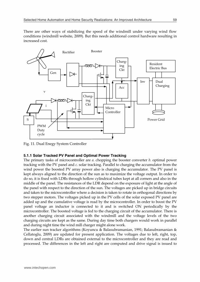
5.1 Control Unit and Generation of Electricity The dual energy system extracting the electrical energy from the wind and solar resources is shown in Fig.11. The windmill has a tail part in it which aligns itself to the direction of the wind as to extract the maximum energy from the wind and no electronic controller is needed. The speed of rotation of the blades and hence the voltage output from the generator will be maximum if the plane of the blades is facing normal to the direction of the wind. The AC voltage generated is boosted to a higher level with the help of booster converter employing inductor diode and electronic switch (FET) controlled form the microcontroller. Based on sensing the voltage of the windmill the microcontroller arranges PWM pulses for controlling the duty cycle as to boost the voltage level. Through a well designed charging circuit it charges the chain of accumulators to save the energy extracted from wind in terms of DC voltage. The DC voltage from accumulator is converted into AC voltage of the standard of the country and is extended to the residential electrical load through dual direction (net metering website, 2009) running energy meter. If windmill is working at its full speed generating 1KW power and if the residential appliances are not taking this power then the power will be fed to the power grid making the meter to rotate in other direction selling energy to the grid. The rotating speed of windmill depends on wind flow rate. The frequency of the AC voltage and power depends on wind flow. As the wind flow is non uniform, the frequency of the AC is fluctuating with the wind speed. This AC cannot be directly taken to the household appliances with varying frequency. Therefore, AC is converted into DC and saved in accumulators. After then it is inverted to AC again by switching DC into 50Hz rate as to make the standard 50Hz frequency useful for household appliances.
There are other ways of stabilizing the speed of the windmill under varying wind flow conditions (windmill website, 2009). But this needs additional control hardware resulting in increased cost.
Fig. 11. Dual Enegy System Controller
5.1.1 Solar Tracked PV Panel and Optimal Power Tracking The primary tasks of microcontroller are a. chopping the booster converter b. optimal power tracking with the PV panel and c. solar tracking. Parallel to charging the accumulator from the wind power the boosted PV array power also is charging the accumulator. The PV panel is kept always aligned to the direction of the sun as to maximize the voltage output. In order to do so, it is fixed with LDRs through hollow cylindrical tubes kept at all corners and also in the middle of the panel. The resistances of the LDR depend on the exposure of light at the angle of the panel with respect to the direction of the sun. The voltages are picked up in bridge circuits and taken to the microcontroller where a decision is taken to rotate in orthogonal directions by two stepper motors. The voltages picked up in the PV cells of the solar exposed PV panel are added up and the cumulative voltage is read by the microcontroller. In order to boost the PV panel voltage an inductor is connected to it and is switched ON periodically by the microcontroller. The boosted voltage is fed to the charging circuit of the accumulator. There is another charging circuit associated with the windmill and the voltage levels of the two charging circuits are kept as the same. During day time both chargers would work in parallel and during night time the wind mill charger might alone work. The earlier sun tracker algorithms (Koyuncu & Balasubramanian, 1991; Balasubramanian & Cellatoglu, 2009) are updated for present application. The voltages due to left, right, top, down and central LDRs are obtained external to the microcontroller and they are read and processed. The differences in the left and right are computed and drive signal is issued to
Gen
Charg-ing Ckt
Acc
Inv Dual Charging
Resident Electric Bus
Charg-ing Ckt
Micro Controller
S Power Grid
Rectifier Booster
v
i
PWM Duty cycle
www.intechopen.com
Selected Home Automation and Home Security Realizations: An Improved Architecture 59
4.3 Security Threats and Countermeasures As internet and email are used as remote control methods of controlling the appliances there is every chance for security threats to occur. The threats occurring through internet such as virus can be overcome by installing appropriate antivirus software. The use of commercially available home automation control devices may interfere each other due to mismatch in protocol and might cause interruption in their services. Since the proposed architecture uses commonly available relays its functioning being clear it doesn’t encounter such difficulties. The monitoring program can be periodically reactivated and updated by the concerned software package available with the user. This can accommodate including additional devices included in the smart home.
5. Mini Electricity Generation Unit for Home
Cost effective and compact electricity generation units depending on renewable energy resources has been reported in the past (Balasubramanian et al, 2009). A mini electricity generation unit working with automatic direction controlled solar panel and mini wind mill. This extracts maximized energy from the solar and wind energy. The voltage developed in the solar panel is used to charge an accumulator as to preserve the electrical energy. The AC voltage from windmill is rectified, boosted and also saved in accumulator. The accumulator voltage is inverted to have regulated frequency and delivered to home. This unit satisfies some percentage of home electricity consumption.
5.1 Control Unit and Generation of Electricity The dual energy system extracting the electrical energy from the wind and solar resources is shown in Fig.11. The windmill has a tail part in it which aligns itself to the direction of the wind as to extract the maximum energy from the wind and no electronic controller is needed. The speed of rotation of the blades and hence the voltage output from the generator will be maximum if the plane of the blades is facing normal to the direction of the wind. The AC voltage generated is boosted to a higher level with the help of booster converter employing inductor diode and electronic switch (FET) controlled form the microcontroller. Based on sensing the voltage of the windmill the microcontroller arranges PWM pulses for controlling the duty cycle as to boost the voltage level. Through a well designed charging circuit it charges the chain of accumulators to save the energy extracted from wind in terms of DC voltage. The DC voltage from accumulator is converted into AC voltage of the standard of the country and is extended to the residential electrical load through dual direction (net metering website, 2009) running energy meter. If windmill is working at its full speed generating 1KW power and if the residential appliances are not taking this power then the power will be fed to the power grid making the meter to rotate in other direction selling energy to the grid. The rotating speed of windmill depends on wind flow rate. The frequency of the AC voltage and power depends on wind flow. As the wind flow is non uniform, the frequency of the AC is fluctuating with the wind speed. This AC cannot be directly taken to the household appliances with varying frequency. Therefore, AC is converted into DC and saved in accumulators. After then it is inverted to AC again by switching DC into 50Hz rate as to make the standard 50Hz frequency useful for household appliances.
There are other ways of stabilizing the speed of the windmill under varying wind flow conditions (windmill website, 2009). But this needs additional control hardware resulting in increased cost.
Fig. 11. Dual Enegy System Controller
5.1.1 Solar Tracked PV Panel and Optimal Power Tracking The primary tasks of microcontroller are a. chopping the booster converter b. optimal power tracking with the PV panel and c. solar tracking. Parallel to charging the accumulator from the wind power the boosted PV array power also is charging the accumulator. The PV panel is kept always aligned to the direction of the sun as to maximize the voltage output. In order to do so, it is fixed with LDRs through hollow cylindrical tubes kept at all corners and also in the middle of the panel. The resistances of the LDR depend on the exposure of light at the angle of the panel with respect to the direction of the sun. The voltages are picked up in bridge circuits and taken to the microcontroller where a decision is taken to rotate in orthogonal directions by two stepper motors. The voltages picked up in the PV cells of the solar exposed PV panel are added up and the cumulative voltage is read by the microcontroller. In order to boost the PV panel voltage an inductor is connected to it and is switched ON periodically by the microcontroller. The boosted voltage is fed to the charging circuit of the accumulator. There is another charging circuit associated with the windmill and the voltage levels of the two charging circuits are kept as the same. During day time both chargers would work in parallel and during night time the wind mill charger might alone work. The earlier sun tracker algorithms (Koyuncu & Balasubramanian, 1991; Balasubramanian & Cellatoglu, 2009) are updated for present application. The voltages due to left, right, top, down and central LDRs are obtained external to the microcontroller and they are read and processed. The differences in the left and right are computed and drive signal is issued to
Gen
Charg-ing Ckt
Acc
Inv Dual Charging
Resident Electric Bus
Charg-ing Ckt
Micro Controller
S Power Grid
Rectifier Booster
v
i
PWM Duty cycle
www.intechopen.com
Smart Home Systems60
one motor. Likewise, the difference in voltages due to top and bottom LDRs is computed and drive pattern is obtained for driving the other stepper motor. The sun tracker algorithm and the hardware arrangement keep the panel rotated from east direction to west direction all along the day tracking the sun. After sunset, with a delay of a predetermined period of time, the panel is brought to east direction step by step as to keep it set ready for facing the sun next day. The sun tracker algorithm and power tracking algorithm are performed simultaneously in an interleaved manner.
6. Conclusion
There are several smart home devices with their control units available in practice. The appliances are connected to the concerned bus and the switching is monitored with their software. For instance X10 devices (website 2009) which are used in communication protocols are employed in home automation applications. This needs the x10 transceivers to be installed at desired nodes. This project does not rely on any commercial smart home devices and the control is effected by simple means through relays which are commonly known to everybody. In case of arising any fault performing the fault diagnosis is quite easy. When smart home devices of different makes are used there is a quite possibility of mismatch to occur when control actions are effected from common software. When internet is involved in effecting control actions to devices of various makes the security threats are more vulnerable. In the proposed relay based control the security threats could be easily handled. Based on the information provided here, one can build the system incorporating the facilities required for his flat in the building. We don’t normally apply the controlled switching for all electrical appliances in the flat. When the resident is away he would like only a very few devices to be operated as to serve certain needs arising at any moment. Therefore, we considered only selected devices to be operated under controlled action besides the manual switching facilities available for the same. Keeping the requirements of modern home automation system accommodating most desirable features the home automation system has been designed and reported. The selected appliances to control by remotely through phone and internet and also by local means are taken as example only. Although, it satisfies most requirements of consumers, if in case the user wants to control few additional devices it can easily accommodated. Timers associated with the monitor program installed in the PC can be programmed to switch on cyclically the selected appliances for security concerns. For instance, the periodical illumination of lamps by a timer would simulate the condition of resident staying in the flat. The solar panels and windmills concede a part of electrical energy requirements of the flat. Since the panel and windmill are kept on the roof their clear exposure to sun and wind would extract maximum energy and this is aided by direction alignment act. The extraction of energy from these resources becomes important nowadays due to the shortage of main resources such as fossil fuels. The security measures are efficient with the authorized visitor entry, control of appliances and intruder detection. The presentation is made in a simple way that one can easily follow and develop and the technology is open for anyone to accommodate more features by adjusting the hardware and software.
7. References
http://www.homeautomationforum.com, 2009. http://www.home-automation.org/, 2009. Jorge Caleira Nunes and Sérgio Jardim da Silva, “Adding intelligence to home automation
systems”, http://www.iadis.net/dl/final_uploads/200401C044.pdf Renato Nunes, “Demobus-A New Approach to Home Automation”, Proceedings of 8th
International Congress on Electrical Engineering, Portugal, July2003. K. Balasubramanian and A.Cellatoglu, “Improvements in Home Automation Strategies for
Designing Apparatus for Efficient Smart Home”, IEEE Trans. on Cons. Electronics, Vol 54 , No 4, Nov 2008, pp 1681-1687.
http://www.mobile-phone-directory.org/Glossary/C/Cellular_Phone.html 2009 K. Balasubramanian, “Control appliances remotely via the telephone”, Electronics World, Vol
109, No 1809, Sep 2003, pp 20-21. http://www.tyntec.biz/ 2009 K. Balasubramanian and A.Cellatoglu, “Intruder Detection and its Remote Intimation by
Autodialling”, Proceedings of the First International Conference on Emerging Technologies and Applications in Engineering, Technology and Sciences, Rajkot, India, Jan 2008, Vol–I, pp 550-555.
K. Balasubramanian, H.Camur and Rajaravivarma, “Microprocessor based Video Door Entry System: A Supplement to Home Automation”, Abstracts of the 1999 IEEE SoutheastCON Conference, Lexinton, Kentucky, USA, Mar 1999.
K. Balasubramanian, "Multi-time zoned digital clock", IEEE Trans on Cons. Electron, Vol 37, No 4, Nov 1991, pp 867-872.
K. Balasubramanian, A.Yasli and A.Cellatoglu “Dual Energy System Design for Wind and Solar Resources Meeting Residential Energy Needs in North Cyprus”, Proceedings of the National Conference on Emerging Trends in Engineering Technology and Applications (NCETETA-2009), Bangalore, Apr 2009, pp 391-396.
http://apps1.eere.energy.gov/states/alternatives/net_metering.cfm , 2009 http://en.wikipedia.org/wiki/Wind_power, 2009 B. Koyuncu and K. Balasubramanian, "Microprocessor controlled automatic sun tracker",
IEEE Trans on Cons. Electron, Vol 37, No 4, Nov 1991, pp 913-917. K. Balasubramanian and A.Cellatoglu, “Optimized solar panel and wind mill alignment
system for full utilization of solar and wind energy for consumer use”, Proceedings of the International Conference on Energy Engineering, Pondicherry, India, (ICEE-2009), Jan 2009.
www.x10control.com , 2009
www.intechopen.com
Selected Home Automation and Home Security Realizations: An Improved Architecture 61
one motor. Likewise, the difference in voltages due to top and bottom LDRs is computed and drive pattern is obtained for driving the other stepper motor. The sun tracker algorithm and the hardware arrangement keep the panel rotated from east direction to west direction all along the day tracking the sun. After sunset, with a delay of a predetermined period of time, the panel is brought to east direction step by step as to keep it set ready for facing the sun next day. The sun tracker algorithm and power tracking algorithm are performed simultaneously in an interleaved manner.
6. Conclusion
There are several smart home devices with their control units available in practice. The appliances are connected to the concerned bus and the switching is monitored with their software. For instance X10 devices (website 2009) which are used in communication protocols are employed in home automation applications. This needs the x10 transceivers to be installed at desired nodes. This project does not rely on any commercial smart home devices and the control is effected by simple means through relays which are commonly known to everybody. In case of arising any fault performing the fault diagnosis is quite easy. When smart home devices of different makes are used there is a quite possibility of mismatch to occur when control actions are effected from common software. When internet is involved in effecting control actions to devices of various makes the security threats are more vulnerable. In the proposed relay based control the security threats could be easily handled. Based on the information provided here, one can build the system incorporating the facilities required for his flat in the building. We don’t normally apply the controlled switching for all electrical appliances in the flat. When the resident is away he would like only a very few devices to be operated as to serve certain needs arising at any moment. Therefore, we considered only selected devices to be operated under controlled action besides the manual switching facilities available for the same. Keeping the requirements of modern home automation system accommodating most desirable features the home automation system has been designed and reported. The selected appliances to control by remotely through phone and internet and also by local means are taken as example only. Although, it satisfies most requirements of consumers, if in case the user wants to control few additional devices it can easily accommodated. Timers associated with the monitor program installed in the PC can be programmed to switch on cyclically the selected appliances for security concerns. For instance, the periodical illumination of lamps by a timer would simulate the condition of resident staying in the flat. The solar panels and windmills concede a part of electrical energy requirements of the flat. Since the panel and windmill are kept on the roof their clear exposure to sun and wind would extract maximum energy and this is aided by direction alignment act. The extraction of energy from these resources becomes important nowadays due to the shortage of main resources such as fossil fuels. The security measures are efficient with the authorized visitor entry, control of appliances and intruder detection. The presentation is made in a simple way that one can easily follow and develop and the technology is open for anyone to accommodate more features by adjusting the hardware and software.
7. References
http://www.homeautomationforum.com, 2009. http://www.home-automation.org/, 2009. Jorge Caleira Nunes and Sérgio Jardim da Silva, “Adding intelligence to home automation
systems”, http://www.iadis.net/dl/final_uploads/200401C044.pdf Renato Nunes, “Demobus-A New Approach to Home Automation”, Proceedings of 8th
International Congress on Electrical Engineering, Portugal, July2003. K. Balasubramanian and A.Cellatoglu, “Improvements in Home Automation Strategies for
Designing Apparatus for Efficient Smart Home”, IEEE Trans. on Cons. Electronics, Vol 54 , No 4, Nov 2008, pp 1681-1687.
http://www.mobile-phone-directory.org/Glossary/C/Cellular_Phone.html 2009 K. Balasubramanian, “Control appliances remotely via the telephone”, Electronics World, Vol
109, No 1809, Sep 2003, pp 20-21. http://www.tyntec.biz/ 2009 K. Balasubramanian and A.Cellatoglu, “Intruder Detection and its Remote Intimation by
Autodialling”, Proceedings of the First International Conference on Emerging Technologies and Applications in Engineering, Technology and Sciences, Rajkot, India, Jan 2008, Vol–I, pp 550-555.
K. Balasubramanian, H.Camur and Rajaravivarma, “Microprocessor based Video Door Entry System: A Supplement to Home Automation”, Abstracts of the 1999 IEEE SoutheastCON Conference, Lexinton, Kentucky, USA, Mar 1999.
K. Balasubramanian, "Multi-time zoned digital clock", IEEE Trans on Cons. Electron, Vol 37, No 4, Nov 1991, pp 867-872.
K. Balasubramanian, A.Yasli and A.Cellatoglu “Dual Energy System Design for Wind and Solar Resources Meeting Residential Energy Needs in North Cyprus”, Proceedings of the National Conference on Emerging Trends in Engineering Technology and Applications (NCETETA-2009), Bangalore, Apr 2009, pp 391-396.
http://apps1.eere.energy.gov/states/alternatives/net_metering.cfm , 2009 http://en.wikipedia.org/wiki/Wind_power, 2009 B. Koyuncu and K. Balasubramanian, "Microprocessor controlled automatic sun tracker",
IEEE Trans on Cons. Electron, Vol 37, No 4, Nov 1991, pp 913-917. K. Balasubramanian and A.Cellatoglu, “Optimized solar panel and wind mill alignment
system for full utilization of solar and wind energy for consumer use”, Proceedings of the International Conference on Energy Engineering, Pondicherry, India, (ICEE-2009), Jan 2009.
www.x10control.com , 2009
www.intechopen.com
Smart Home Systems62
www.intechopen.com
Smart Home SystemsEdited by Mahmoud A. Al-Qutayri
ISBN 978-953-307-050-6Hard cover, 194 pagesPublisher InTechPublished online 01, February, 2010Published in print edition February, 2010
InTech EuropeUniversity Campus STeP Ri Slavka Krautzeka 83/A 51000 Rijeka, Croatia Phone: +385 (51) 770 447 Fax: +385 (51) 686 166www.intechopen.com
InTech ChinaUnit 405, Office Block, Hotel Equatorial Shanghai No.65, Yan An Road (West), Shanghai, 200040, China
Phone: +86-21-62489820 Fax: +86-21-62489821
Smart homes are intelligent environments that interact dynamically and respond readily in an adaptive mannerto the needs of the occupants and changes in the ambient conditions. The realization of systems that supportthe smart homes concept requires integration of technologies from different fields. Among the challenges thatthe designers face is to make all the components of the system interact in a seamless, reliable and securemanner. Another major challenge is to design the smart home in a way that takes into account the wayhumans live and interact. This later aspect requires input from the humanities and social sciences fields. Theneed for input from diverse fields of knowledge reflects the multidisciplinary nature of the research anddevelopment effort required to realize smart homes that are acceptable to the general public. The applicationsthat can be supported by a smart home are very wide and their degree of sophistication depends on theunderlying technology used. Some of the application areas include monitoring and control of appliances,security, telemedicine, entertainment, location based services, care for children and the elderly… etc. Thisbook consists of eleven chapters that cover various aspects of smart home systems.
How to referenceIn order to correctly reference this scholarly work, feel free to copy and paste the following:
K. Balasubramanian and A. Cellatoglu (2010). Selected Home Automation and Home Security Realizations: AnImproved Architecture, Smart Home Systems, Mahmoud A. Al-Qutayri (Ed.), ISBN: 978-953-307-050-6,InTech, Available from: http://www.intechopen.com/books/smart-home-systems/selected-home-automation-and-home-security-realizations-an-improved-architecture

© 2010 The Author(s). Licensee IntechOpen. This chapter is distributedunder the terms of the Creative Commons Attribution-NonCommercial-ShareAlike-3.0 License, which permits use, distribution and reproduction fornon-commercial purposes, provided the original is properly cited andderivative works building on this content are distributed under the samelicense.