instruction manual transformer protection relay grt100 - Toshiba

Instruction Manual
20150130
SEL-787 RelayTransformer Protection Relay
Instruction Manual
*PM787-01-NB*

SEL-787 Relay Instruction Manual Date Code 20150130
© 2006–2015 by Schweitzer Engineering Laboratories, Inc. All rights reserved.
All brand or product names appearing in this document are the trademark or registered trademark of their respective holders. No SEL trademarks may be used without written permission. SEL products appearing in this document may be covered by U.S. and Foreign patents.
Schweitzer Engineering Laboratories, Inc. reserves all rights and benefits afforded under federal and international copyright and patent laws in its products, including without limitation software, firmware, and documentation.
The information in this document is provided for informational use only and is subject to change without notice. Schweitzer Engineering Laboratories, Inc. has approved only the English language document.
This product is covered by the standard SEL 10-year warranty. For warranty details, visit www.selinc.com or contact your customer service representative. PM787-01
Date Code 20150130 Instruction Manual SEL-787 Relay
Table of ContentsInstruction Manual
List of Tables ....................................................................................................................................................... v
List of Figures .................................................................................................................................................... xi
Preface ............................................................................................................................................................... xviiManual Overview ........................................................................................................................................... xviiSafety Information.........................................................................................................................................xviiiGeneral Information ........................................................................................................................................ xxi
Section 1: Introduction and SpecificationsOverview ......................................................................................................................................................... 1.1Features............................................................................................................................................................ 1.1Models, Options, and Accessories................................................................................................................... 1.2Applications..................................................................................................................................................... 1.4Getting Started................................................................................................................................................. 1.4Specifications .................................................................................................................................................. 1.9
Section 2: InstallationOverview ......................................................................................................................................................... 2.1Relay Placement .............................................................................................................................................. 2.1I/O Configuration ............................................................................................................................................ 2.2Rear-Panel Connections ................................................................................................................................ 2.18AC/DC Control Connection Diagrams.......................................................................................................... 2.22Field Serviceability........................................................................................................................................ 2.31
Section 3: PC SoftwareOverview ......................................................................................................................................................... 3.1Setup ................................................................................................................................................................ 3.2Terminal........................................................................................................................................................... 3.4Settings Database Management and Drivers ................................................................................................... 3.5Settings ............................................................................................................................................................ 3.6Event Analysis............................................................................................................................................... 3.10Meter and Control.......................................................................................................................................... 3.12ACSELERATOR QuickSet Help ...................................................................................................................... 3.14
Section 4: Protection and Logic FunctionsOverview ......................................................................................................................................................... 4.1Application Data.............................................................................................................................................. 4.2Group Settings (SET Command)..................................................................................................................... 4.2Basic Protection............................................................................................................................................... 4.5RTD-Based Protection................................................................................................................................... 4.46Voltage-Based Protection .............................................................................................................................. 4.48Demand Metering.......................................................................................................................................... 4.62Trip/Close Logic............................................................................................................................................ 4.67Logic Settings (SET L Command) ................................................................................................................ 4.70Global Settings (SET G Command) .............................................................................................................. 4.81Port Settings (SET P Command)................................................................................................................... 4.94Front-Panel Settings (SET F Command)....................................................................................................... 4.97Report Settings (SET R Command) ............................................................................................................ 4.108DNP Map Settings (SET DNP n Command, n = 1, 2, or 3)........................................................................................4.110Modbus Map Settings (SET M Command)................................................................................................. 4.111
ii
SEL-787 Relay Instruction Manual Date Code 20150130
Table of Contents
Section 5: Metering and MonitoringOverview ......................................................................................................................................................... 5.1Power Measurement Conventions ................................................................................................................... 5.2Metering .......................................................................................................................................................... 5.3Small Signal Cutoff for Metering.................................................................................................................. 5.12Load Profiling................................................................................................................................................ 5.12Through-Fault Event Monitoring .................................................................................................................. 5.13
Section 6: SettingsOverview ......................................................................................................................................................... 6.1View/Change Settings With Front Panel ......................................................................................................... 6.2View/Change Settings Over Communications Port......................................................................................... 6.4Setting Entry Error Messages.......................................................................................................................... 6.6
SEL-787 Settings Sheets
Section 7: CommunicationsOverview ......................................................................................................................................................... 7.1Communications Interfaces ............................................................................................................................. 7.1Communications Protocols............................................................................................................................ 7.10SEL ASCII Protocol and Commands ............................................................................................................ 7.14
Section 8: Front-Panel OperationsOverview ......................................................................................................................................................... 8.1Front-Panel Layout .......................................................................................................................................... 8.1Human-Machine Interface............................................................................................................................... 8.2Operation and Target LEDs........................................................................................................................... 8.12
Section 9: Analyzing EventsOverview ......................................................................................................................................................... 9.1Event Reporting............................................................................................................................................... 9.2Sequential Events Recorder (SER) Report.................................................................................................... 9.22
Section 10: Testing and TroubleshootingOverview ....................................................................................................................................................... 10.1Testing Tools.................................................................................................................................................. 10.1Commissioning Tests..................................................................................................................................... 10.3Periodic Tests (Routine Maintenance)......................................................................................................... 10.10Self-Test....................................................................................................................................................... 10.11Troubleshooting........................................................................................................................................... 10.15Factory Assistance....................................................................................................................................... 10.15
Appendix A: Firmware and Manual VersionsFirmware......................................................................................................................................................... A.1ICD File .......................................................................................................................................................... A.7Instruction Manual........................................................................................................................................ A.10
Appendix B: Firmware Upgrade InstructionsOverview .........................................................................................................................................................B.1Upgrade Firmware Using ACSELERATOR QuickSet .......................................................................................B.2Upgrade Firmware Using a Terminal Emulator ..............................................................................................B.6Relays With IEC 61850 Option.......................................................................................................................B.8Factory Assistance...........................................................................................................................................B.9
iii
Date Code 20150130 Instruction Manual SEL-787 Relay
Table of Contents
Appendix C: SEL Communications ProcessorsSEL Communications Protocols......................................................................................................................C.1SEL Communications Processor .....................................................................................................................C.3SEL Communications Processor and Relay Architecture ...............................................................................C.5
Appendix D: DNP3 CommunicationsOverview ........................................................................................................................................................ D.1Introduction to DNP3 ..................................................................................................................................... D.1DNP3 in the SEL-787..................................................................................................................................... D.6DNP3 Documentation .................................................................................................................................. D.13
Appendix E: Modbus RTU CommunicationsOverview .........................................................................................................................................................E.1Communications Protocol ...............................................................................................................................E.2Modbus Register Map ...................................................................................................................................E.23
Appendix F: IEC 61850 CommunicationsFeatures............................................................................................................................................................ F.1Introduction to IEC 61850............................................................................................................................... F.2IEC 61850 Operation....................................................................................................................................... F.3IEC 61850 Configuration .............................................................................................................................. F.11Logical Node Extensions............................................................................................................................... F.13Logical Nodes................................................................................................................................................ F.15Protocol Implementation Conformance Statement ....................................................................................... F.29ACSI Conformance Statements..................................................................................................................... F.35
Appendix G: DeviceNet CommunicationsOverview ........................................................................................................................................................ G.1DeviceNet Card .............................................................................................................................................. G.2Features........................................................................................................................................................... G.2Electronic Data Sheet ..................................................................................................................................... G.3
Appendix H: SynchrophasorsIntroduction .................................................................................................................................................... H.1Synchrophasor Measurement ......................................................................................................................... H.2Settings for Synchrophasors ........................................................................................................................... H.4Synchrophasor Relay Word Bits..................................................................................................................... H.9View Synchrophasors Using the MET PM Command................................................................................. H.10C37.118 Synchrophasor Protocol................................................................................................................. H.11
Appendix I: MIRRORED BITS CommunicationsOverview .......................................................................................................................................................... I.1Operation .......................................................................................................................................................... I.1Settings ............................................................................................................................................................. I.5
Appendix J: Relay Word BitsOverview ..........................................................................................................................................................J.1Definitions ........................................................................................................................................................J.4
Appendix K: Analog Quantities
Glossary
Index
SEL-787 Relay Command Summary

This page intentionally left blank
Date Code 20150130 Instruction Manual SEL-787 Relay
List of TablesInstruction Manual Table 1.1 SEL-787 Serial Port Settings.................................................................................................. 1.6
Table 2.1 Power Supply Card Inputs Terminal Designation.................................................................. 2.4Table 2.2 Communication Ports ............................................................................................................. 2.4Table 2.3 Communication Card Interfaces and Connectors................................................................... 2.5Table 2.4 6 ACI Current Card Inputs Terminal Designation ................................................................. 2.6Table 2.5 1 ACI/3 AVI or 1 ACI Current/Voltage Card Inputs Terminal Designation .......................... 2.7Table 2.6 Four Analog Input/Four Analog Output (4 AI/4 AO) Card Terminal Allocation .................. 2.7Table 2.7 I/O (3 DI/4 DO/1 AO) Card Terminal Allocation .................................................................. 2.8Table 2.8 RTD (10 RTD) Card Terminal Allocation.............................................................................. 2.8Table 2.9 Four Digital Input/Four Digital Output (4 DI/4 DO) Card Terminal Allocation ................... 2.9Table 2.10 Eight Digital Input (8 DI) Card Terminal Allocation............................................................. 2.9Table 2.11 Four Digital Inputs, One Form-B Digital Output, Two Form-C Digital Outputs
(4 DI/3DO) Card Terminal Allocation ............................................................................. 2.10Table 2.12 Jumper Functions and Default Positions.............................................................................. 2.16Table 2.13 Typical Maximum RTD Lead Length .................................................................................. 2.21Table 3.1 SEL Software Solutions ......................................................................................................... 3.1Table 3.2 ACSELERATOR QuickSet SEL-5030 Software....................................................................... 3.1Table 3.3 File/Tools Menus.................................................................................................................... 3.7Table 3.4 ACSELERATOR QuickSet Help............................................................................................. 3.14Table 4.1 Identifier Settings ................................................................................................................... 4.2Table 4.2 Configurations and Ratings (Phase CTs, Power Transformer) .............................................. 4.3Table 4.3 Configurations and Ratings (Optional Neutral CT, Phase PT) .............................................. 4.4Table 4.4 Differential Element Settings ............................................................................................... 4.10Table 4.5 Preferred Compensation Settings (W1CTC and W2CTC) .................................................. 4.22Table 4.6 Restricted Earth Fault Settings ............................................................................................. 4.33Table 4.7 Winding n Maximum Phase Overcurrent Settings (n = 1 or 2)............................................ 4.34Table 4.8 Winding n Residual Overcurrent Settings (n = 1, 2) ............................................................ 4.37Table 4.9 Winding n Negative-Sequence Overcurrent Settings (n = 1 or 2)........................................ 4.37Table 4.10 Winding n Maximum Phase Time-Overcurrent (n = 1 or 2) ................................................ 4.38Table 4.11 Winding n Phase A, B, and C Time-Overcurrent (n = 1 or 2) .................................................... 4.39Table 4.12 Residual Time-Overcurrent Settings (n = 1 or 2)................................................................. 4.40Table 4.13 Winding n Negative-Sequence Time-Overcurrent Settings (n = 1, 2) ...................................... 4.41Table 4.14 Neutral Overcurrent Settings................................................................................................ 4.41Table 4.15 Neutral Time-Overcurrent Settings ...................................................................................... 4.42Table 4.16 Equations Associated With U.S. Curves .............................................................................. 4.43Table 4.17 Equations Associated With IEC Curves............................................................................... 4.43Table 4.18 RTD Settings ........................................................................................................................ 4.46Table 4.19 RTD Resistance Versus Temperature ................................................................................... 4.47Table 4.20 Undervoltage Settings .......................................................................................................... 4.48Table 4.21 Overvoltage Settings ............................................................................................................ 4.49Table 4.22 Volts Per Hertz Settings........................................................................................................ 4.53Table 4.23 Power Element Settings........................................................................................................ 4.58Table 4.24 Frequency Settings ............................................................................................................... 4.60Table 4.25 Demand Meter Settings........................................................................................................ 4.62Table 4.26 Trip/Close Logic Settings..................................................................................................... 4.67Table 4.27 Enable Settings..................................................................................................................... 4.70Table 4.28 Latch Bits Equation Settings ................................................................................................ 4.72Table 4.29 SELOGIC Control Equation Operators (Listed in Operator Precedence) ............................. 4.74Table 4.30 Other SELOGIC Control Equation Operators/Values............................................................ 4.77Table 4.31 SELOGIC Variable Settings................................................................................................... 4.77Table 4.32 Counter Input/Output Description........................................................................................ 4.78Table 4.33 Order of Precedence of the Control Inputs........................................................................... 4.79
vi List of Tables
SEL-787 Relay Instruction Manual Date Code 20150130
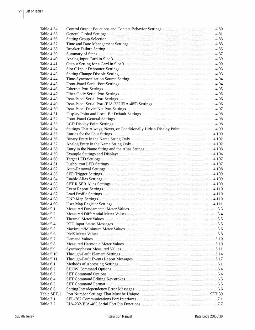
Table 4.34 Control Output Equations and Contact Behavior Settings................................................... 4.80Table 4.35 General Global Settings ....................................................................................................... 4.81Table 4.36 Setting Group Selection ....................................................................................................... 4.83Table 4.37 Time and Date Management Settings .................................................................................. 4.83Table 4.38 Breaker Failure Setting......................................................................................................... 4.85Table 4.39 Summary of Steps ................................................................................................................ 4.87Table 4.40 Analog Input Card in Slot 3 ................................................................................................. 4.89Table 4.41 Output Setting for a Card in Slot 3....................................................................................... 4.90Table 4.42 Slot C Input Debounce Settings ........................................................................................... 4.93Table 4.43 Setting Change Disable Setting............................................................................................ 4.93Table 4.44 Time-Synchronization Source Setting.................................................................................. 4.94Table 4.45 Front-Panel Serial Port Settings ........................................................................................... 4.94Table 4.46 Ethernet Port Settings........................................................................................................... 4.95Table 4.47 Fiber-Optic Serial Port Settings ........................................................................................... 4.95Table 4.48 Rear-Panel Serial Port Settings ............................................................................................ 4.96Table 4.49 Rear-Panel Serial Port (EIA-232/EIA-485) Settings............................................................ 4.96Table 4.50 Rear-Panel DeviceNet Port Settings..................................................................................... 4.97Table 4.51 Display Point and Local Bit Default Settings ...................................................................... 4.98Table 4.52 Front-Panel General Settings ............................................................................................... 4.98Table 4.53 LCD Display Point Settings ................................................................................................. 4.98Table 4.54 Settings That Always, Never, or Conditionally Hide a Display Point ................................. 4.99Table 4.55 Entries for the Four Strings ................................................................................................ 4.100Table 4.56 Binary Entry in the Name String Only............................................................................... 4.102Table 4.57 Analog Entry in the Name String Only.............................................................................. 4.102Table 4.58 Entry in the Name String and the Alias Strings ................................................................. 4.103Table 4.59 Example Settings and Displays .......................................................................................... 4.104Table 4.60 Target LED Settings ........................................................................................................... 4.107Table 4.61 Pushbutton LED Settings ................................................................................................... 4.107Table 4.62 Auto-Removal Settings ...................................................................................................... 4.108Table 4.63 SER Trigger Settings.......................................................................................................... 4.109Table 4.64 Enable Alias Settings ......................................................................................................... 4.109Table 4.65 SET R SER Alias Settings ................................................................................................. 4.109Table 4.66 Event Report Settings......................................................................................................... 4.110Table 4.67 Load Profile Settings .......................................................................................................... 4.110Table 4.68 DNP Map Settings.............................................................................................................. 4.110Table 4.69 User Map Register Settings ............................................................................................... 4.111Table 5.1 Measured Fundamental Meter Values .................................................................................... 5.3Table 5.2 Measured Differential Meter Values ...................................................................................... 5.4Table 5.3 Thermal Meter Values ............................................................................................................ 5.5Table 5.4 RTD Input Status Messages ................................................................................................... 5.5Table 5.5 Maximum/Minimum Meter Values........................................................................................ 5.6Table 5.6 RMS Meter Values ................................................................................................................. 5.8Table 5.7 Demand Values..................................................................................................................... 5.10Table 5.8 Measured Harmonic Meter Values....................................................................................... 5.10Table 5.9 Synchrophasor Measured Values ......................................................................................... 5.11Table 5.10 Through-Fault Element Settings .......................................................................................... 5.14Table 5.11 Through-Fault Events Report Messages .............................................................................. 5.17Table 6.1 Methods of Accessing Settings .............................................................................................. 6.1Table 6.2 SHOW Command Options..................................................................................................... 6.4Table 6.3 SET Command Options ......................................................................................................... 6.4Table 6.4 SET Command Editing Keystrokes........................................................................................ 6.5Table 6.5 SET Command Format........................................................................................................... 6.5Table 6.6 Setting Interdependency Error Messages ............................................................................... 6.6Table SET.1 Port Number Settings That Must be Unique ................................................................... SET.39Table 7.1 SEL-787 Communications Port Interfaces............................................................................. 7.1Table 7.2 EIA-232/EIA-485 Serial Port Pin Functions ......................................................................... 7.7
viiList of Tables
Date Code 20150130 Instruction Manual SEL-787 Relay
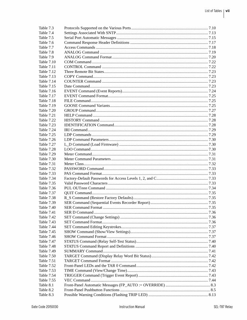
Table 7.3 Protocols Supported on the Various Ports ............................................................................ 7.10Table 7.4 Settings Associated With SNTP........................................................................................... 7.13Table 7.5 Serial Port Automatic Messages .......................................................................................... 7.15Table 7.6 Command Response Header Definitions ............................................................................. 7.17Table 7.7 Access Commands ............................................................................................................... 7.18Table 7.8 ANALOG Command ........................................................................................................... 7.19Table 7.9 ANALOG Command Format ............................................................................................... 7.20Table 7.10 COM Command ................................................................................................................... 7.22Table 7.11 CONTROL Command ......................................................................................................... 7.22Table 7.12 Three Remote Bit States....................................................................................................... 7.23Table 7.13 COPY Command.................................................................................................................. 7.23Table 7.14 COUNTER Command ......................................................................................................... 7.23Table 7.15 Date Command..................................................................................................................... 7.23Table 7.16 EVENT Command (Event Reports)..................................................................................... 7.24Table 7.17 EVENT Command Format................................................................................................... 7.25Table 7.18 FILE Command.................................................................................................................... 7.25Table 7.19 GOOSE Command Variants................................................................................................. 7.25Table 7.20 GROUP Command............................................................................................................... 7.27Table 7.21 HELP Command .................................................................................................................. 7.28Table 7.22 HISTORY Command ........................................................................................................... 7.28Table 7.23 IDENTIFICATION Command............................................................................................. 7.28Table 7.24 IRI Command....................................................................................................................... 7.29Table 7.25 LDP Commands ................................................................................................................... 7.29Table 7.26 LDP Command Parameters .................................................................................................. 7.30Table 7.27 L_D Command (Load Firmware) ........................................................................................ 7.30Table 7.28 LOO Command .................................................................................................................... 7.30Table 7.29 Meter Command................................................................................................................... 7.31Table 7.30 Meter Command Parameters ................................................................................................ 7.31Table 7.31 Meter Class........................................................................................................................... 7.32Table 7.32 PASSWORD Command....................................................................................................... 7.33Table 7.33 PAS Command Format......................................................................................................... 7.33Table 7.34 Factory-Default Passwords for Access Levels 1, 2, and C................................................... 7.33Table 7.35 Valid Password Characters ................................................................................................... 7.33Table 7.36 PUL OUTnnn Command ..................................................................................................... 7.34Table 7.37 QUIT Command................................................................................................................... 7.35Table 7.38 R_S Command (Restore Factory Defaults).......................................................................... 7.35Table 7.39 SER Command (Sequential Events Recorder Report) ......................................................... 7.35Table 7.40 SER Command Format ........................................................................................................ 7.35Table 7.41 SER D Command ................................................................................................................. 7.36Table 7.42 SET Command (Change Settings) ....................................................................................... 7.36Table 7.43 SET Command Format......................................................................................................... 7.36Table 7.44 SET Command Editing Keystrokes...................................................................................... 7.37Table 7.45 SHOW Command (Show/View Settings)............................................................................. 7.37Table 7.46 SHOW Command Format .................................................................................................... 7.37Table 7.47 STATUS Command (Relay Self-Test Status)....................................................................... 7.40Table 7.48 STATUS Command Report and Definitions ........................................................................ 7.40Table 7.49 SUMMARY Command........................................................................................................ 7.41Table 7.50 TARGET Command (Display Relay Word Bit Status) ........................................................ 7.42Table 7.51 TARGET Command Format ................................................................................................ 7.42Table 7.52 Front-Panel LEDs and the TAR 0 Command....................................................................... 7.42Table 7.53 TIME Command (View/Change Time)................................................................................ 7.43Table 7.54 TRIGGER Command (Trigger Event Report) ..................................................................... 7.43Table 7.55 VEC Command .................................................................................................................... 7.44Table 8.1 Front-Panel Automatic Messages (FP_AUTO := OVERRIDE) ............................................ 8.3Table 8.2 Front-Panel Pushbutton Functions ......................................................................................... 8.5Table 8.3 Possible Warning Conditions (Flashing TRIP LED) ........................................................... 8.13
viii List of Tables
SEL-787 Relay Instruction Manual Date Code 20150130
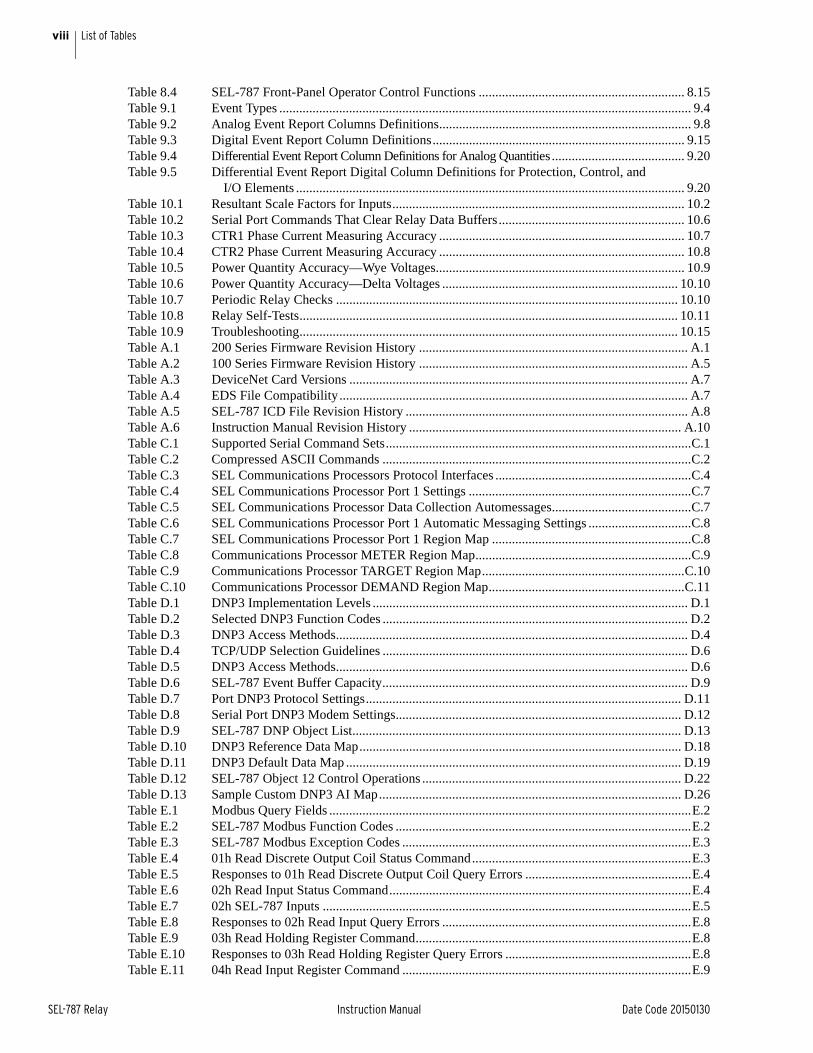
Table 8.4 SEL-787 Front-Panel Operator Control Functions .............................................................. 8.15Table 9.1 Event Types ............................................................................................................................ 9.4Table 9.2 Analog Event Report Columns Definitions............................................................................ 9.8Table 9.3 Digital Event Report Column Definitions............................................................................ 9.15Table 9.4 Differential Event Report Column Definitions for Analog Quantities ........................................ 9.20Table 9.5 Differential Event Report Digital Column Definitions for Protection, Control, and
I/O Elements ..................................................................................................................... 9.20Table 10.1 Resultant Scale Factors for Inputs........................................................................................ 10.2Table 10.2 Serial Port Commands That Clear Relay Data Buffers........................................................ 10.6Table 10.3 CTR1 Phase Current Measuring Accuracy .......................................................................... 10.7Table 10.4 CTR2 Phase Current Measuring Accuracy .......................................................................... 10.8Table 10.5 Power Quantity Accuracy—Wye Voltages........................................................................... 10.9Table 10.6 Power Quantity Accuracy—Delta Voltages ....................................................................... 10.10Table 10.7 Periodic Relay Checks ....................................................................................................... 10.10Table 10.8 Relay Self-Tests.................................................................................................................. 10.11Table 10.9 Troubleshooting.................................................................................................................. 10.15Table A.1 200 Series Firmware Revision History ................................................................................. A.1Table A.2 100 Series Firmware Revision History ................................................................................. A.5Table A.3 DeviceNet Card Versions ...................................................................................................... A.7Table A.4 EDS File Compatibility......................................................................................................... A.7Table A.5 SEL-787 ICD File Revision History ..................................................................................... A.8Table A.6 Instruction Manual Revision History .................................................................................. A.10Table C.1 Supported Serial Command Sets............................................................................................C.1Table C.2 Compressed ASCII Commands .............................................................................................C.2Table C.3 SEL Communications Processors Protocol Interfaces ...........................................................C.4Table C.4 SEL Communications Processor Port 1 Settings ...................................................................C.7Table C.5 SEL Communications Processor Data Collection Automessages..........................................C.7Table C.6 SEL Communications Processor Port 1 Automatic Messaging Settings ...............................C.8Table C.7 SEL Communications Processor Port 1 Region Map ............................................................C.8Table C.8 Communications Processor METER Region Map.................................................................C.9Table C.9 Communications Processor TARGET Region Map.............................................................C.10Table C.10 Communications Processor DEMAND Region Map...........................................................C.11Table D.1 DNP3 Implementation Levels ............................................................................................... D.1Table D.2 Selected DNP3 Function Codes ............................................................................................ D.2Table D.3 DNP3 Access Methods.......................................................................................................... D.4Table D.4 TCP/UDP Selection Guidelines ............................................................................................ D.6Table D.5 DNP3 Access Methods.......................................................................................................... D.6Table D.6 SEL-787 Event Buffer Capacity............................................................................................ D.9Table D.7 Port DNP3 Protocol Settings............................................................................................... D.11Table D.8 Serial Port DNP3 Modem Settings...................................................................................... D.12Table D.9 SEL-787 DNP Object List................................................................................................... D.13Table D.10 DNP3 Reference Data Map................................................................................................. D.18Table D.11 DNP3 Default Data Map ..................................................................................................... D.19Table D.12 SEL-787 Object 12 Control Operations .............................................................................. D.22Table D.13 Sample Custom DNP3 AI Map........................................................................................... D.26Table E.1 Modbus Query Fields .............................................................................................................E.2Table E.2 SEL-787 Modbus Function Codes .........................................................................................E.2Table E.3 SEL-787 Modbus Exception Codes .......................................................................................E.3Table E.4 01h Read Discrete Output Coil Status Command..................................................................E.3Table E.5 Responses to 01h Read Discrete Output Coil Query Errors ..................................................E.4Table E.6 02h Read Input Status Command...........................................................................................E.4Table E.7 02h SEL-787 Inputs ...............................................................................................................E.5Table E.8 Responses to 02h Read Input Query Errors ...........................................................................E.8Table E.9 03h Read Holding Register Command...................................................................................E.8Table E.10 Responses to 03h Read Holding Register Query Errors ........................................................E.8Table E.11 04h Read Input Register Command .......................................................................................E.9
ixList of Tables
Date Code 20150130 Instruction Manual SEL-787 Relay
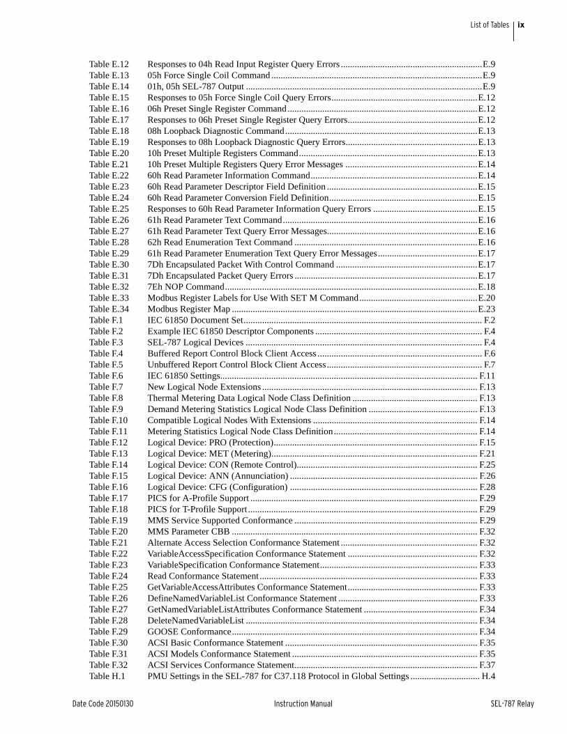
Table E.12 Responses to 04h Read Input Register Query Errors .............................................................E.9Table E.13 05h Force Single Coil Command ...........................................................................................E.9Table E.14 01h, 05h SEL-787 Output ......................................................................................................E.9Table E.15 Responses to 05h Force Single Coil Query Errors...............................................................E.12Table E.16 06h Preset Single Register Command..................................................................................E.12Table E.17 Responses to 06h Preset Single Register Query Errors........................................................E.12Table E.18 08h Loopback Diagnostic Command...................................................................................E.13Table E.19 Responses to 08h Loopback Diagnostic Query Errors.........................................................E.13Table E.20 10h Preset Multiple Registers Command.............................................................................E.13Table E.21 10h Preset Multiple Registers Query Error Messages .........................................................E.14Table E.22 60h Read Parameter Information Command........................................................................E.14Table E.23 60h Read Parameter Descriptor Field Definition .................................................................E.15Table E.24 60h Read Parameter Conversion Field Definition................................................................E.15Table E.25 Responses to 60h Read Parameter Information Query Errors .............................................E.15Table E.26 61h Read Parameter Text Command....................................................................................E.16Table E.27 61h Read Parameter Text Query Error Messages.................................................................E.16Table E.28 62h Read Enumeration Text Command ...............................................................................E.16Table E.29 61h Read Parameter Enumeration Text Query Error Messages...........................................E.17Table E.30 7Dh Encapsulated Packet With Control Command .............................................................E.17Table E.31 7Dh Encapsulated Packet Query Errors ...............................................................................E.17Table E.32 7Eh NOP Command.............................................................................................................E.18Table E.33 Modbus Register Labels for Use With SET M Command...................................................E.20Table E.34 Modbus Register Map ..........................................................................................................E.23Table F.1 IEC 61850 Document Set....................................................................................................... F.2Table F.2 Example IEC 61850 Descriptor Components ........................................................................ F.4Table F.3 SEL-787 Logical Devices ...................................................................................................... F.4Table F.4 Buffered Report Control Block Client Access ....................................................................... F.6Table F.5 Unbuffered Report Control Block Client Access................................................................... F.7Table F.6 IEC 61850 Settings............................................................................................................... F.11Table F.7 New Logical Node Extensions ............................................................................................. F.13Table F.8 Thermal Metering Data Logical Node Class Definition ...................................................... F.13Table F.9 Demand Metering Statistics Logical Node Class Definition ............................................... F.13Table F.10 Compatible Logical Nodes With Extensions ....................................................................... F.14Table F.11 Metering Statistics Logical Node Class Definition.............................................................. F.14Table F.12 Logical Device: PRO (Protection)........................................................................................ F.15Table F.13 Logical Device: MET (Metering)......................................................................................... F.21Table F.14 Logical Device: CON (Remote Control).............................................................................. F.25Table F.15 Logical Device: ANN (Annunciation) ................................................................................. F.26Table F.16 Logical Device: CFG (Configuration) ................................................................................. F.28Table F.17 PICS for A-Profile Support .................................................................................................. F.29Table F.18 PICS for T-Profile Support ................................................................................................... F.29Table F.19 MMS Service Supported Conformance ............................................................................... F.29Table F.20 MMS Parameter CBB .......................................................................................................... F.32Table F.21 Alternate Access Selection Conformance Statement ........................................................... F.32Table F.22 VariableAccessSpecification Conformance Statement ........................................................ F.32Table F.23 VariableSpecification Conformance Statement.................................................................... F.33Table F.24 Read Conformance Statement.............................................................................................. F.33Table F.25 GetVariableAccessAttributes Conformance Statement........................................................ F.33Table F.26 DefineNamedVariableList Conformance Statement ............................................................ F.33Table F.27 GetNamedVariableListAttributes Conformance Statement ................................................. F.34Table F.28 DeleteNamedVariableList .................................................................................................... F.34Table F.29 GOOSE Conformance.......................................................................................................... F.34Table F.30 ACSI Basic Conformance Statement ................................................................................... F.35Table F.31 ACSI Models Conformance Statement ................................................................................ F.35Table F.32 ACSI Services Conformance Statement............................................................................... F.37Table H.1 PMU Settings in the SEL-787 for C37.118 Protocol in Global Settings .............................. H.4
x List of Tables
SEL-787 Relay Instruction Manual Date Code 20150130
Table H.2 SEL-787 Serial Port Settings for Synchrophasors ................................................................ H.5Table H.3 Synchrophasor Order in Data Stream (Voltages and Currents)............................................. H.7Table H.4 User-Defined Analog Values Selected by the NUMANA Setting ........................................ H.7Table H.5 User-Defined Digital Status Words Selected by the NUMDSW Setting .............................. H.8Table H.6 PM Trigger Reason Bits—IEEE C37.118 Assignments ....................................................... H.8Table H.7 Synchrophasor Trigger Relay Word Bits ............................................................................ H.10Table H.8 Time Synchronization Relay Word Bits.............................................................................. H.10Table H.9 Size of a C37.118 Synchrophasor Message ........................................................................ H.12Table H.10 Serial Port Bandwidth for Synchrophasors (in Bytes) ........................................................ H.12Table I.1 Number of MIRRORED BITS Messages for Different Baud ..................................................... I.2Table I.2 Positions of the MIRRORED BITS............................................................................................. I.3Table I.3 MIRRORED BITS Values for a RXDFLT Setting of 10100111................................................. I.3Table I.4 MIRRORED BITS Communications Message Transmission Period.......................................... I.5Table I.5 MIRRORED BITS Protocol Settings .......................................................................................... I.5Table J.1 SEL-787 Relay Word Bits.......................................................................................................J.1Table J.2 Relay Word Bit Definitions for the SEL-787 ..........................................................................J.4Table K.1 Analog Quantities.................................................................................................................. K.1
Date Code 20150130 Instruction Manual SEL-787 Relay
List of FiguresInstruction Manual
Figure 1.1 Response Header........................................................................................................................ 1.5Figure 1.2 STA Command Response—No DeviceNet Communications Card or EIA-232/EIA-485
Communications Card........................................................................................................... 1.6Figure 1.3 STA Command Response—With DeviceNet Communications Card ....................................... 1.7Figure 2.1 Relay Panel-Mount Dimensions................................................................................................ 2.2Figure 2.2 Slot Allocations for Different Cards.......................................................................................... 2.3Figure 2.3 Circuit Board of Analog I/O Board, Showing Jumper Selection............................................. 2.13Figure 2.4 JMP1 Through JMP4 Locations on 4 AI/4 AO Board............................................................. 2.14Figure 2.5 Current Output Jumpers........................................................................................................... 2.15Figure 2.6 Voltage Output Jumpers........................................................................................................... 2.15Figure 2.7 Pins for Password Jumper, Breaker Control Jumper, and SELBOOT Jumper .......................... 2.15Figure 2.8 Rear-Panel Connections of Selected Cards.............................................................................. 2.17Figure 2.9 Dual-Fiber, Ethernet, EIA-232 Communication, 3 DI/4 DO/1 AO, and Current/Voltage
(1 ACI/3 AVI) Option ......................................................................................................... 2.18Figure 2.10 Single Copper Ethernet, 8 DI, RTD, and 4 AI/4 AO Option .................................................. 2.18Figure 2.11 DeviceNet, Fast Hybrid 4 DI/4 DO, and Current/Voltage Option .......................................... 2.19Figure 2.12 Control I/O Connections—4 AI/4 AO Option in Slot D and Fiber-Optic Port in Slot B........ 2.20Figure 2.13 Control I/O Connections—Internal RTD Option .................................................................... 2.21Figure 2.14 Analog Output Wiring Example .............................................................................................. 2.21Figure 2.15 Output OUT103 Relay Output Contact Configuration............................................................ 2.22Figure 2.16 OUT103 Contact Fail-Safe and Nonfail-Safe Options ............................................................ 2.22Figure 2.17 Single-Phase Voltage Connections .......................................................................................... 2.23Figure 2.18 Voltage Connections ................................................................................................................ 2.24Figure 2.19 Typical Current Connections ................................................................................................... 2.25Figure 2.20 SEL-787 Provides Basic Two-Winding Transformer Differential Protection......................... 2.26Figure 2.21 SEL-787 Provides Two-Winding Transformer Differential Protection
With REF (Restricted Earth Fault) Protection .................................................................... 2.27Figure 2.22 SEL-787 Provides Two-Winding Transformer Differential Protection
With REF and Voltage-Based Protection ............................................................................ 2.28Figure 2.23 SEL-787 Provides Autotransformer Differential Protection, Including REF Protection ........ 2.29Figure 2.24 Example DC Connections ....................................................................................................... 2.30Figure 3.1 Serial Port Communication Dialog Box .................................................................................... 3.2Figure 3.2 Serial Port Communication Parameters Dialog Box ................................................................. 3.3Figure 3.3 Network Communication Parameters Dialog Box .................................................................... 3.3Figure 3.4 Tools Menu ................................................................................................................................ 3.4Figure 3.5 Device Response to the ID Command ....................................................................................... 3.4Figure 3.6 Selection of Drivers ................................................................................................................... 3.7Figure 3.7 Update Part Number .................................................................................................................. 3.7Figure 3.8 New Setting Screen.................................................................................................................... 3.8Figure 3.9 Expressions Created With Expression Builder .......................................................................... 3.9Figure 3.10 Composite Screens for Retrieving Events ............................................................................... 3.10Figure 3.11 Saving the Retrieved Event...................................................................................................... 3.11Figure 3.12 Device Overview Screen.......................................................................................................... 3.12Figure 3.13 Control Screen ......................................................................................................................... 3.13Figure 3.14 Remote Operation Selection .................................................................................................... 3.14Figure 4.1 Percentage Restraint Differential Characteristic........................................................................ 4.6Figure 4.2 Winding 1 Compensated Currents ............................................................................................. 4.7Figure 4.3 Differential Element (87-1) Quantities ...................................................................................... 4.8Figure 4.4 Differential Element Decision Logic......................................................................................... 4.9Figure 4.5 Differential Element Harmonic Blocking Logic ..................................................................... 4.10
xii List of Figures
SEL-787 Relay Instruction Manual Date Code 20150130
Figure 4.6 Differential Current Alarm Logic Diagram ............................................................................. 4.11Figure 4.7 Winding Connections, Phase Shifts, and Compensation Direction......................................... 4.17Figure 4.8 Example 1 for WnCTC Selection ............................................................................................ 4.19Figure 4.9 Example 2 for WnCTC Selection ............................................................................................ 4.21Figure 4.10 SEL-787 Differential Characteristics (Preferred and Other) ................................................... 4.23Figure 4.11 REF Directional Element......................................................................................................... 4.30Figure 4.12 REF1 Enable Logic.................................................................................................................. 4.31Figure 4.13 REF1 Directional Element ...................................................................................................... 4.31Figure 4.14 REF Element Trip Output........................................................................................................ 4.32Figure 4.15 Internal Fault With LV Breaker Open...................................................................................... 4.32Figure 4.16 REF Protection Output (Extremely Inverse-Time O/C) .......................................................... 4.33Figure 4.17 Single-Wye Winding REF Application (REF1POL := 2)........................................................ 4.34Figure 4.18 Autotransformer REF Application (REF1POL := 12)............................................................. 4.34Figure 4.19 Instantaneous Overcurrent Element Logic............................................................................... 4.36Figure 4.20 Maximum Phase Time-Overcurrent Elements 51P1T and 51P2T........................................... 4.38Figure 4.21 Phase A, B, and C Time-Overcurrent Elements ...................................................................... 4.39Figure 4.22 Residual Time-Overcurrent Elements 51G1T and 51G2T ...................................................... 4.40Figure 4.23 Negative-Sequence Time-Overcurrent Element 51Q1T and 51Q2T....................................... 4.41Figure 4.24 Neutral Time-Overcurrent Elements 51N1T and 51N2T ........................................................ 4.42Figure 4.25 U.S. Moderately Inverse Curve: U1......................................................................................... 4.44Figure 4.26 U.S. Inverse Curve: U2 ............................................................................................................ 4.44Figure 4.27 U.S. Very Inverse Curve: U3 ................................................................................................... 4.44Figure 4.28 U.S. Extremely Inverse Curve: U4 .......................................................................................... 4.44Figure 4.29 U.S. Short-Time Inverse Curve: U5......................................................................................... 4.45Figure 4.30 IEC Class A Curve (Standard Inverse): C1 ............................................................................. 4.45Figure 4.31 IEC Class B Curve (Very Inverse): C2 .................................................................................... 4.45Figure 4.32 IEC Class C Curve (Extremely Inverse): C3.............................................................................. 4.45Figure 4.33 IEC Long-Time Inverse Curve: C4.......................................................................................... 4.46Figure 4.34 IEC Short-Time Inverse Curve: C5.......................................................................................... 4.46Figure 4.35 Undervoltage Element Logic ................................................................................................... 4.49Figure 4.36 Overvoltage Element Logic ..................................................................................................... 4.50Figure 4.37 V/Hz Element Logic ................................................................................................................ 4.51Figure 4.38 Dual-Level Volts/Hertz Time-Delay Characteristic, 24CCS = DD......................................... 4.52Figure 4.39 Composite Inverse/Definite-Time Overexcitation Characteristic, 24CCS = ID...................... 4.52Figure 4.40 Volts/Hertz Inverse-Time Characteristic, 24IC = 0.5 .............................................................. 4.55Figure 4.41 Volts/Hertz Inverse-Time Characteristic, 24IC = 1 ................................................................. 4.56Figure 4.42 Volts/Hertz Inverse-Time Characteristic, 24IC = 2 ................................................................. 4.57Figure 4.43 Three-Phase Power Elements Logic........................................................................................ 4.58Figure 4.44 Power Elements Operation in the Real/Reactive Power Plane................................................ 4.59Figure 4.45 Over- and Underfrequency Element Logic.............................................................................. 4.60Figure 4.46 Loss-of-Potential (LOP) Logic................................................................................................ 4.62Figure 4.47 Demand Current Logic Outputs............................................................................................... 4.63Figure 4.48 Response of Thermal and Rolling Demand Meters to a Step Input
(Setting DMTC = 15 minutes) ............................................................................................ 4.64Figure 4.49 Voltage VS Applied to Series RC Circuit ................................................................................ 4.65Figure 4.50 Trip Logic ................................................................................................................................ 4.68Figure 4.51 Close Logic .............................................................................................................................. 4.69Figure 4.52 Schematic Diagram of a Traditional Latching Device............................................................. 4.71Figure 4.53 Logic Diagram of a Latch Switch............................................................................................ 4.71Figure 4.54 SELOGIC Control Equation Variable/Timers SV01/SV01T–SV32T....................................... 4.73Figure 4.55 Result of Falling-Edge Operator on a Deasserting Input......................................................... 4.76Figure 4.56 Example Use of SELOGIC Variables/Timers............................................................................ 4.77Figure 4.57 Counter 01................................................................................................................................ 4.78
xiiiList of Figures
Date Code 20150130 Instruction Manual SEL-787 Relay
Figure 4.58 Example of the Effects of the Input Precedence...................................................................... 4.79Figure 4.59 Phase Rotation Setting ............................................................................................................. 4.82Figure 4.60 Breaker Failure Logic .............................................................................................................. 4.86Figure 4.61 Analog Input Card Adaptive Name ......................................................................................... 4.86Figure 4.62 Settings to Configure Input 1 as a 4–20 mA Transducer Measuring Temperatures
Between –50°C and 150°C ................................................................................................. 4.89Figure 4.63 Analog Output Number Allocation.......................................................................................... 4.90Figure 4.64 Analog Output Settings............................................................................................................ 4.91Figure 4.65 DC Mode Processing ............................................................................................................... 4.91Figure 4.66 AC Mode Processing ............................................................................................................... 4.92Figure 4.67 Timing Diagram for Debounce Timer Operation When Operating in AC Mode.................... 4.92Figure 4.68 Display Point Settings............................................................................................................ 4.100Figure 4.69 Front-Panel Display—Both HV and LV Breakers Open ....................................................... 4.100Figure 4.70 Front-Panel Display—HV Breaker Closed, LV Breaker Open ............................................. 4.101Figure 4.71 Front-Panel Display—Both HV and LV Breakers Closed..................................................... 4.101Figure 4.72 Front-Panel Display—HV Breaker Open, LV Breaker Closed ............................................. 4.101Figure 4.73 Front-Panel Display—HV Breaker Open, LV Breaker Closed ............................................. 4.101Figure 4.74 Front-Panel Display for a Binary Entry in the Name String Only......................................... 4.102Figure 4.75 Front-Panel Display for an Analog Entry in the Name String Only...................................... 4.103Figure 4.76 Front-Panel Display for an Entry in (a) Boolean Name and Alias Strings and
(b) Analog Name and User Text and Formatting Strings.................................................. 4.103Figure 4.77 Front-Panel Display for an Entry in (a) Boolean Name and Alias Strings and
(b) Analog Name, User Text and Formatting Strings, and Engineering Units ................. 4.103Figure 4.78 Adding Temperature Measurement Display Points ............................................................... 4.104Figure 4.79 Rotating Display .................................................................................................................... 4.105Figure 4.80 Adding Two Local Bits .......................................................................................................... 4.106Figure 5.1 Complex Power Measurement Conventions .............................................................................. 5.2Figure 5.2 METER Command Report With Voltage Option ...................................................................... 5.4Figure 5.3 METER DIF (Differential) Command Report........................................................................... 5.5Figure 5.4 METER T Command Report With RTDs.................................................................................. 5.5Figure 5.5 METER E Command Report ..................................................................................................... 5.6Figure 5.6 METER RE Command Report .................................................................................................. 5.6Figure 5.7 METER M Command Report.................................................................................................... 5.7Figure 5.8 METER RM Command Response............................................................................................. 5.8Figure 5.9 MET MV Command Report ...................................................................................................... 5.8Figure 5.10 METER RMS Command Report ............................................................................................... 5.9Figure 5.11 METER AI Command Report ................................................................................................... 5.9Figure 5.12 METER DEM Command Report ............................................................................................ 5.10Figure 5.13 METER P Command Report ................................................................................................... 5.10Figure 5.14 METER H Command Report .................................................................................................. 5.11Figure 5.15 LDP Command Report ............................................................................................................ 5.12Figure 5.16 Transformer Bank Subjected to Through Fault ....................................................................... 5.13Figure 5.17 Category IV Transformers Through-Fault Protection Curves ................................................. 5.13Figure 5.18 Through-Fault Diagram........................................................................................................... 5.15Figure 5.19 Result of the TFE Command ................................................................................................... 5.17Figure 5.20 Preload the Values of the Accumulated Data........................................................................... 5.18Figure 6.1 Front-Panel Setting Entry Example........................................................................................... 6.3Figure 7.1 Simple Ethernet Network Configuration ................................................................................... 7.3Figure 7.2 Ethernet Network Configuration With Dual Redundant Connections (Failover Mode) ........... 7.3Figure 7.3 Ethernet Network Configuration With Ring Structure (Switched Mode) ................................. 7.4Figure 7.4 IRIG-B Input (Relay Terminals B01–B02) ............................................................................... 7.5Figure 7.5 IRIG-B Input Via EIA-232 Port 3 (SEL Communications Processor as Source) ..................... 7.6Figure 7.6 IRIG-B Input Via EIA-232 Port 3 (SEL-2401/2404/2407 Time Source).................................. 7.6Figure 7.7 IRIG-B Input VIA Fiber-Optic EIA-232 Port 2 (SEL-2030/2032 Time Source)...................... 7.6
xiv List of Figures
SEL-787 Relay Instruction Manual Date Code 20150130
Figure 7.8 IRIG-B Input VIA Fiber-Optic EIA-232 Port 2 (SEL-2401/2404/2407 Time Source) .............7.7Figure 7.9 EIA-232 DB-9 Connector Pin Numbers ....................................................................................7.7Figure 7.10 SEL Cable C234A—SEL-787 to DTE Device..........................................................................7.8Figure 7.11 SEL Cable C227A—SEL-787 to DTE Device..........................................................................7.8Figure 7.12 SEL Cable C222—SEL-787 to Modem ....................................................................................7.8Figure 7.13 SEL Cable C272A—SEL-787 to SEL Communications Processor
(Without IRIG-B Signal) .......................................................................................................7.9Figure 7.14 SEL Cable C273A—SEL-787 to SEL Communications Processor (With IRIG-B Signal)......7.9Figure 7.15 SEL Cable C387—SEL-787 to SEL-3010 ................................................................................7.9Figure 7.16 Ethernet Port (PORT 1) Status Report .....................................................................................7.24Figure 7.17 Non-Redundant Port Response ................................................................................................7.24Figure 7.18 GOOSE Command Response ..................................................................................................7.27Figure 7.19 PING Command Response ......................................................................................................7.34Figure 7.20 SHOW Command Example .....................................................................................................7.38Figure 7.21 Typical Relay Output for STATUS S Command......................................................................7.41Figure 8.1 Front-Panel Overview ................................................................................................................8.2Figure 8.2 Access Level Security Padlock Symbol .....................................................................................8.3Figure 8.3 Password Entry Screen...............................................................................................................8.4Figure 8.4 Front-Panel Pushbuttons.............................................................................................................8.4Figure 8.5 Main Menu .................................................................................................................................8.5Figure 8.6 MAIN Menu and METER Submenu .........................................................................................8.6Figure 8.7 METER Menu and ENERGY Submenu....................................................................................8.6Figure 8.8 Relay Response When Demand, Peak Demand, Energy, or Max/Min Metering Is Reset.........8.6Figure 8.9 Relay Response When No Analog Cards Are Installed.............................................................8.6Figure 8.10 Relay Response When No Math Variables Enabled ..................................................................8.7Figure 8.11 MAIN Menu and EVENTS Submenu........................................................................................8.7Figure 8.12 EVENTS Menu and DISPLAY Submenu..................................................................................8.7Figure 8.13 Relay Response When No Event Data Available.......................................................................8.7Figure 8.14 Relay Response When Events Are Cleared ...............................................................................8.7Figure 8.15 MAIN Menu and TARGETS Submenu .....................................................................................8.8Figure 8.16 TARGETS Menu Navigation .....................................................................................................8.8Figure 8.17 MAIN Menu and CONTROL Submenu ....................................................................................8.8Figure 8.18 CONTROL Menu and OUTPUTS Submenu.............................................................................8.9Figure 8.19 CONTROL Menu and LOCAL BITS Submenu........................................................................8.9Figure 8.20 MAIN Menu and SET/SHOW Submenu .................................................................................8.10Figure 8.21 SET/SHOW Menu ...................................................................................................................8.11Figure 8.22 MAIN Menu and Status Submenu ...........................................................................................8.12Figure 8.23 Factory-Default Front-Panel LEDs ..........................................................................................8.12Figure 8.24 Target Reset Pushbutton ...........................................................................................................8.13Figure 8.25 Operator Control Pushbuttons and LEDs.................................................................................8.14Figure 9.1 Example Event Summary...........................................................................................................9.3Figure 9.2 Sample Event History.................................................................................................................9.6Figure 9.3 Example Standard 15-Cycle Analog Event Report 1/4-Cycle Resolution.................................9.9Figure 9.4 Derivation of Analog Event Report Current Values and RMS Current Values From
Sampled Current Waveform ................................................................................................9.13Figure 9.5 Derivation of Phasor RMS Current Values From Event Report Current Values......................9.14Figure 9.6 Example Standard 15-cycle Digital Event Report (EVE D Command)
1/4 Cycle Resolution ...........................................................................................................9.18Figure 9.7 Example Standard 15-cycle Differential Event Report (EVE DIF1 Command)
1/4 Cycle Resolution ...........................................................................................................9.21Figure 9.8 Example Sequential Events Recorder (SER) Event Report .....................................................9.23Figure 10.1 Low-Level Test Interface (J2 and J3) .......................................................................................10.2Figure 10.2 Three-Phase Wye AC Connections ..........................................................................................10.5Figure 10.3 Three-Phase Open-Delta AC Connections...............................................................................10.5Figure 10.4 CTR1 Current Source Connections..........................................................................................10.7
xvList of Figures
Date Code 20150130 Instruction Manual SEL-787 Relay
Figure 10.5 CTR2 Current Source Connections ......................................................................................... 10.8Figure 10.6 Wye Voltage Source Connections............................................................................................ 10.8Figure 10.7 Delta Voltage Source Connections........................................................................................... 10.9Figure B.1 Firmware File Transfer Process .................................................................................................B.7Figure C.1 SEL Communications Processor Star Integration Network.......................................................C.3Figure C.2 Multitiered SEL Communications Processor Architecture .......................................................C.4Figure C.3 Enhancing Multidrop Networks With SEL Communications Processors .................................C.6Figure C.4 Example of SEL Relay and SEL Communications Processor Configuration ...........................C.7Figure D.1 Application Confirmation Timing With URETRY n = 2.......................................................... D.7Figure D.2 Message Transmission Timing ................................................................................................. D.8Figure D.3 Sample Response to SHO DNP Command ............................................................................ D.23Figure D.4 Port MAP Command .............................................................................................................. D.24Figure D.5 Sample Custom DNP3 AI Map Settings................................................................................. D.26Figure D.6 Analog Input Map Entry in ACSELERATOR QuickSet Software ............................................ D.27Figure D.7 AI Point Label, Scaling and Dead Band in ACSELERATOR QuickSet Software .................... D.27Figure D.8 Sample Custom DNP3 BO Map Settings ............................................................................... D.28Figure D.9 Binary Output Map Entry in ACSELERATOR QuickSet Software .......................................... D.28Figure F.1 SEL-787 Predefined Reports ..................................................................................................... F.6Figure F.2 SEL-787 Datasets ...................................................................................................................... F.8Figure F.3 Goose Quality ............................................................................................................................ F.9Figure G.1 DeviceNet Card Component Overview .................................................................................... G.2Figure H.1 Phase Reference........................................................................................................................ H.2Figure H.2 Waveform at Relay Terminals May Have a Phase Shift ........................................................... H.3Figure H.3 Correction of Measured Phase Angle ....................................................................................... H.3Figure H.4 Sample MET PM Command Response .................................................................................. H.11

This page intentionally left blank
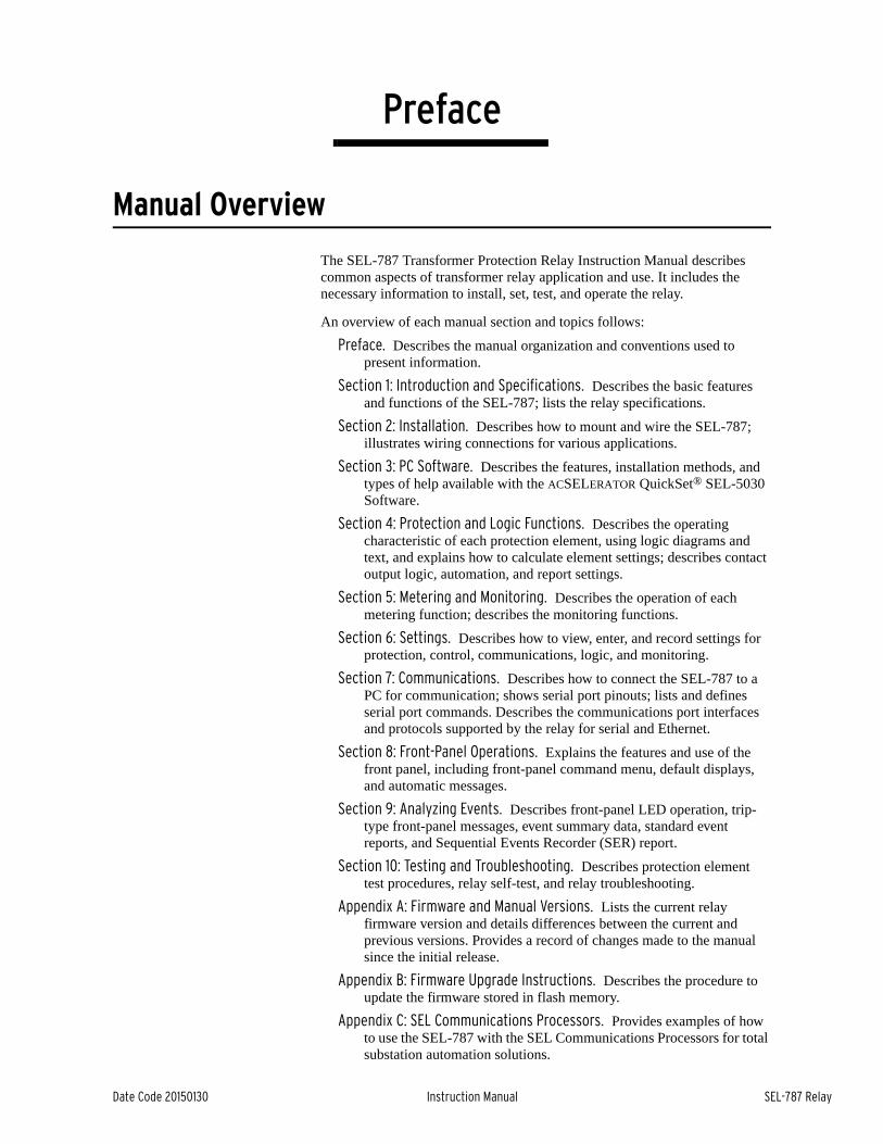
Date Code 20150130 Instruction Manual SEL-787 Relay
PrefaceR.Instruction Manual
Manual Overview
The SEL-787 Transformer Protection Relay Instruction Manual describes common aspects of transformer relay application and use. It includes the necessary information to install, set, test, and operate the relay.
An overview of each manual section and topics follows:
Preface. Describes the manual organization and conventions used to present information.
Section 1: Introduction and Specifications. Describes the basic features and functions of the SEL-787; lists the relay specifications.
Section 2: Installation. Describes how to mount and wire the SEL-787; illustrates wiring connections for various applications.
Section 3: PC Software. Describes the features, installation methods, and types of help available with the ACSELERATOR QuickSet® SEL-5030 Software.
Section 4: Protection and Logic Functions. Describes the operating characteristic of each protection element, using logic diagrams and text, and explains how to calculate element settings; describes contact output logic, automation, and report settings.
Section 5: Metering and Monitoring. Describes the operation of each metering function; describes the monitoring functions.
Section 6: Settings. Describes how to view, enter, and record settings for protection, control, communications, logic, and monitoring.
Section 7: Communications. Describes how to connect the SEL-787 to a PC for communication; shows serial port pinouts; lists and defines serial port commands. Describes the communications port interfaces and protocols supported by the relay for serial and Ethernet.
Section 8: Front-Panel Operations. Explains the features and use of the front panel, including front-panel command menu, default displays, and automatic messages.
Section 9: Analyzing Events. Describes front-panel LED operation, trip-type front-panel messages, event summary data, standard event reports, and Sequential Events Recorder (SER) report.
Section 10: Testing and Troubleshooting. Describes protection element test procedures, relay self-test, and relay troubleshooting.
Appendix A: Firmware and Manual Versions. Lists the current relay firmware version and details differences between the current and previous versions. Provides a record of changes made to the manual since the initial release.
Appendix B: Firmware Upgrade Instructions. Describes the procedure to update the firmware stored in flash memory.
Appendix C: SEL Communications Processors. Provides examples of how to use the SEL-787 with the SEL Communications Processors for total substation automation solutions.
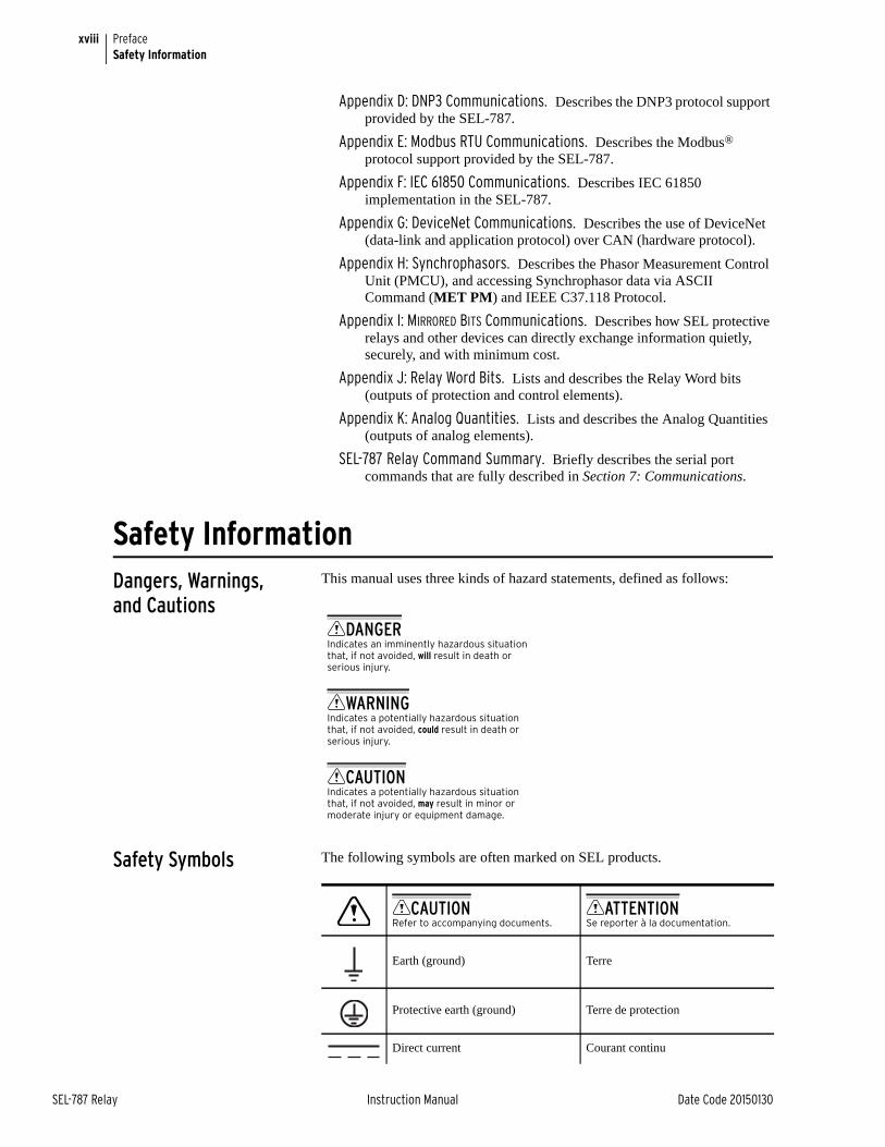
xviii
SEL-787 Relay Instruction Manual Date Code 20150130
PrefaceSafety Information
Appendix D: DNP3 Communications. Describes the DNP3 protocol support provided by the SEL-787.
Appendix E: Modbus RTU Communications. Describes the Modbus® protocol support provided by the SEL-787.
Appendix F: IEC 61850 Communications. Describes IEC 61850 implementation in the SEL-787.
Appendix G: DeviceNet Communications. Describes the use of DeviceNet (data-link and application protocol) over CAN (hardware protocol).
Appendix H: Synchrophasors. Describes the Phasor Measurement Control Unit (PMCU), and accessing Synchrophasor data via ASCII Command (MET PM) and IEEE C37.118 Protocol.
Appendix I: MIRRORED BITS Communications. Describes how SEL protective relays and other devices can directly exchange information quietly, securely, and with minimum cost.
Appendix J: Relay Word Bits. Lists and describes the Relay Word bits (outputs of protection and control elements).
Appendix K: Analog Quantities. Lists and describes the Analog Quantities (outputs of analog elements).
SEL-787 Relay Command Summary. Briefly describes the serial port commands that are fully described in Section 7: Communications.
Safety InformationDangers, Warnings, and Cautions
This manual uses three kinds of hazard statements, defined as follows:
Safety Symbols The following symbols are often marked on SEL products.
DANGERIndicates an imminently hazardous situation that, if not avoided, will result in death or serious injury.
WARNINGIndicates a potentially hazardous situation that, if not avoided, could result in death or serious injury.
CAUTIONIndicates a potentially hazardous situation that, if not avoided, may result in minor or moderate injury or equipment damage.
CAUTIONRefer to accompanying documents.
ATTENTIONSe reporter à la documentation.
Earth (ground) Terre
Protective earth (ground) Terre de protection
Direct current Courant continu
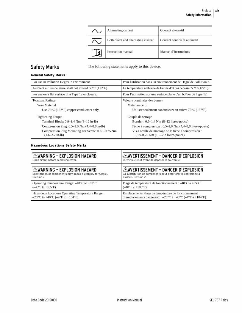
xix
Date Code 20150130 Instruction Manual SEL-787 Relay
PrefaceSafety Information
Safety Marks The following statements apply to this device.
Alternating current Courant alternatif
Both direct and alternating current Courant continu et alternatif
Instruction manual Manuel d’instructions
General Safety Marks
For use in Pollution Degree 2 environment. Pour l'utilisation dans un environnement de Degré de Pollution 2.
Ambient air temperature shall not exceed 50°C (122°F). La température ambiante de l'air ne doit pas dépasser 50°C (122°F).
For use on a flat surface of a Type 12 enclosure. Pour l’utilisation sur une surface plane d'un boîtier de Type 12.
Terminal Ratings
Wire Material
Use 75°C (167°F) copper conductors only.
Valeurs nominales des bornes
Matériau de fil
Utiliser seulement conducteurs en cuivre 75°C (167°F).
Tightening Torque
Terminal Block: 0.9–1.4 Nm (8–12 in-lb)
Compression Plug: 0.5–1.0 Nm (4.4–8.8 in-lb)
Compression Plug Mounting Ear Screw: 0.18–0.25 Nm (1.6–2.2 in-lb)
Couple de serrage
Bornier : 0,9–1,4 Nm (8–12 livres-pouce)
Fiche à compression : 0,5–1,0 Nm (4,4–8,8 livres-pouce)
Vis à oreille de montage de la fiche à compression : 0,18–0,25 Nm (1,6–2,2 livres-pouce)
Hazardous Locations Safety Marks
WARNING – EXPLOSION HAZARDOpen circuit before removing cover.
AVERTISSEMENT – DANGER D'EXPLOSIONOuvrir le circuit avant de déposer le couvercle.
WARNING – EXPLOSION HAZARDSubstitution of components may impair suitability for Class I, Division 2.
AVERTISSEMENT – DANGER D'EXPLOSIONLa substitution de composants peut détériorer la conformité à Classe I, Division 2.
Operating Temperature Range: –40°C to +85°C (–40°F to +185°F).
Plage de température de fonctionnement : –40°C à +85°C (–40°F à +185°F).
Hazardous Locations Operating Temperature Range: –20°C to +40°C (–4°F to +104°F).
Emplacements Plage de température de fonctionnement d’emplacements dangereux : –20°C à +40°C (–4°F à +104°F).
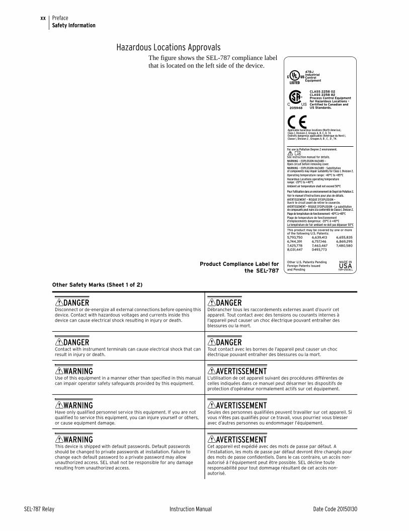
xx
SEL-787 Relay Instruction Manual Date Code 20150130
PrefaceSafety Information
Hazardous Locations ApprovalsThe figure shows the SEL-787 compliance label that is located on the left side of the device.
Product Compliance Label forthe SEL-787
Applicable hazardous locations (North America),Class I, Division 2, Groups A, B, C, D, T4.Endroits dangereux applicables (Amérique du Nord ),Classe I, Division 2 , Groupes A, B , C , D , T4.
CLASS 2258 02CLASS 2258 82Process Control Equipmentfor Hazardous Locations -Certified to Canadian andUS Standards.205948
159-0508.L
Other U.S. Patents PendingForeign Patents Issued and Pending
D493,773
7,463,467 7,480,580
8,031,447
5,793,750 6,639,413 6,655,835
6,744,391 6,757,146 6,869,295
7,425,778
This product may be covered by one or moreof the following U.S. Patents:
La température de l'air ambiant ne doit pas dépasser 50°C
Plage de temperature de fonctionnementd'emplacements dangereux: -20°C à +40°C
Plage de température de fonctionnement: -40°C à +85°C
AVERTISSEMENT – RISQUE D'EXPLOSION - La substitutionde composants peut nuire à la conformité de Classe I, Division 2.
AVERTISSEMENT – RISQUE D'EXPLOSION –Ouvrir le circuit avant de retirer le couvercle.
Voir le manuel d'instructions pour plus de détails.
Pour l'utilisation dans un environnement de Degré de Pollution 2.
Ambient air temperature shall not exceed 50°C
Hazardous Locations operating temperaturerange: -20°C to +40°C
Operating temperature range: -40°C to +85°C
WARNING – EXPLOSION HAZARD - Substitutionof components may impair suitability for Class I, Division 2.
WARNING – EXPLOSION HAZARD –Open circuit before removing cover.
See instruction manual for details.
For use in Pollution Degree 2 environment.
Other Safety Marks (Sheet 1 of 2)
DANGERDisconnect or de-energize all external connections before opening this device. Contact with hazardous voltages and currents inside this device can cause electrical shock resulting in injury or death.
DANGERDébrancher tous les raccordements externes avant d’ouvrir cet appareil. Tout contact avec des tensions ou courants internes à l’appareil peut causer un choc électrique pouvant entraîner des blessures ou la mort.
DANGERContact with instrument terminals can cause electrical shock that can result in injury or death.
DANGERTout contact avec les bornes de l’appareil peut causer un choc électrique pouvant entraîner des blessures ou la mort.
WARNINGUse of this equipment in a manner other than specified in this manual can impair operator safety safeguards provided by this equipment.
AVERTISSEMENTL’utilisation de cet appareil suivant des procédures différentes de celles indiquées dans ce manuel peut désarmer les dispositifs de protection d’opérateur normalement actifs sur cet équipement.
WARNINGHave only qualified personnel service this equipment. If you are not qualified to service this equipment, you can injure yourself or others, or cause equipment damage.
AVERTISSEMENTSeules des personnes qualifiées peuvent travailler sur cet appareil. Si vous n’êtes pas qualifiés pour ce travail, vous pourriez vous blesser avec d’autres personnes ou endommager l’équipement.
WARNINGThis device is shipped with default passwords. Default passwords should be changed to private passwords at installation. Failure to change each default password to a private password may allow unauthorized access. SEL shall not be responsible for any damage resulting from unauthorized access.
AVERTISSEMENTCet appareil est expédié avec des mots de passe par défaut. A l’installation, les mots de passe par défaut devront être changés pour des mots de passe confidentiels. Dans le cas contraire, un accès non-autorisé á l’équipement peut être possible. SEL décline toute responsabilité pour tout dommage résultant de cet accès non-autorisé.
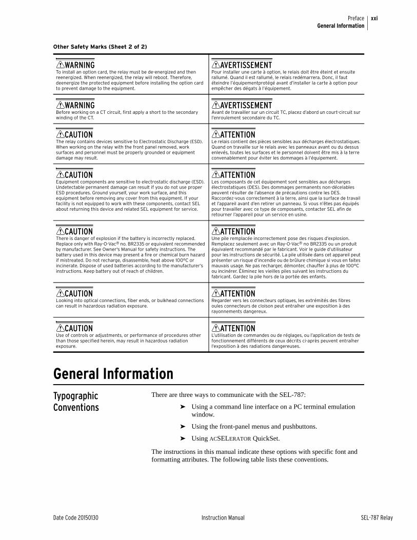
xxi
Date Code 20150130 Instruction Manual SEL-787 Relay
PrefaceGeneral Information
General InformationTypographic Conventions
There are three ways to communicate with the SEL-787:
➤ Using a command line interface on a PC terminal emulation window.
➤ Using the front-panel menus and pushbuttons.
➤ Using ACSELERATOR QuickSet.
The instructions in this manual indicate these options with specific font and formatting attributes. The following table lists these conventions.
WARNINGTo install an option card, the relay must be de-energized and then reenergized. When reenergized, the relay will reboot. Therefore, deenergize the protected equipment before installing the option card to prevent damage to the equipment.
AVERTISSEMENTPour installer une carte à option, le relais doit être éteint et ensuite rallumé. Quand il est rallumé, le relais redémarrera. Donc, il faut éteindre l’équipementprotégé avant d’installer la carte à option pour empêcher des dégats à l’équipement.
WARNINGBefore working on a CT circuit, first apply a short to the secondary winding of the CT.
AVERTISSEMENTAvant de travailler sur un circuit TC, placez d’abord un court-circuit sur l’enroulement secondaire du TC.
CAUTIONThe relay contains devices sensitive to Electrostatic Discharge (ESD). When working on the relay with the front panel removed, work surfaces and personnel must be properly grounded or equipment damage may result.
ATTENTIONLe relais contient des pièces sensibles aux décharges électrostatiques. Quand on travaille sur le relais avec les panneaux avant ou du dessus enlevés, toutes les surfaces et le personnel doivent être mis à la terre convenablement pour éviter les dommages à l’équipement.
CAUTIONEquipment components are sensitive to electrostatic discharge (ESD). Undetectable permanent damage can result if you do not use proper ESD procedures. Ground yourself, your work surface, and this equipment before removing any cover from this equipment. If your facility is not equipped to work with these components, contact SEL about returning this device and related SEL equipment for service.
ATTENTIONLes composants de cet équipement sont sensibles aux décharges électrostatiques (DES). Des dommages permanents non-décelables peuvent résulter de l’absence de précautions contre les DES. Raccordez-vous correctement à la terre, ainsi que la surface de travail et l’appareil avant d’en retirer un panneau. Si vous n’êtes pas équipés pour travailler avec ce type de composants, contacter SEL afin de retourner l’appareil pour un service en usine.
CAUTIONThere is danger of explosion if the battery is incorrectly replaced. Replace only with Ray-O-Vac® no. BR2335 or equivalent recommended by manufacturer. See Owner's Manual for safety instructions. The battery used in this device may present a fire or chemical burn hazard if mistreated. Do not recharge, disassemble, heat above 100°C or incinerate. Dispose of used batteries according to the manufacturer’s instructions. Keep battery out of reach of children.
ATTENTIONUne pile remplacée incorrectement pose des risques d’explosion. Remplacez seulement avec un Ray-O-Vac® no BR2335 ou un produit équivalent recommandé par le fabricant. Voir le guide d’utilisateur pour les instructions de sécurité. La pile utilisée dans cet appareil peut présenter un risque d’incendie ou de brûlure chimique si vous en faites mauvais usage. Ne pas recharger, démonter, chauffer à plus de 100°C ou incinérer. Éliminez les vieilles piles suivant les instructions du fabricant. Gardez la pile hors de la portée des enfants.
CAUTIONLooking into optical connections, fiber ends, or bulkhead connections can result in hazardous radiation exposure.
ATTENTIONRegarder vers les connecteurs optiques, les extrémités des fibres oules connecteurs de cloison peut entraîner une exposition à des rayonnements dangereux.
CAUTIONUse of controls or adjustments, or performance of procedures other than those specified herein, may result in hazardous radiation exposure.
ATTENTIONL’utilisation de commandes ou de réglages, ou l’application de tests de fonctionnement différents de ceux décrits ci-après peuvent entraîner l’exposition à des radiations dangereuses.
Other Safety Marks (Sheet 2 of 2)

xxii
SEL-787 Relay Instruction Manual Date Code 20150130
PrefaceGeneral Information
Examples This instruction manual uses several example illustrations and instructions to explain how to effectively operate the SEL-787. These examples are for demonstration purposes only; the firmware identification information or settings values included in these examples may not necessarily match those in the current version of your SEL-787.
Product Labels The two labels shown below are the Product Labels for the high voltage and low voltage power supply options. The label is located on the left side panel of the product. The label shows the serial number, model number and the ratings of the product.
Example Description
STATUS Commands typed at a command line interface on a PC.
<Enter> Single keystroke on a PC keyboard.
<Ctrl+D> Multiple/combination keystroke on a PC keyboard.
Start > Settings PC dialog boxes and menu selections.The > character indicates submenus.
CLOSE Relay front-panel pushbuttons.
ENABLE Relay front- or rear-panel labels.
Main > Meters Relay front-panel LCD menus and relay responses.The > character indicates submenus.
Temperature
4kV300V
Rated Impulse Withstand (Uimp)
Insulation Voltage (U )i
240V~MAX3A @ 120V
1.5A @ 240V5A
Utilization Category AC-15Contact Rating Designation B300
300VShort-Circuit Rating 1kA
Operational Voltage (U )e
Operational Current (I )e
Insulation Voltage (U )i
Thermal Current (Ithe)
CONTACT OUTPUTS (OUT101-OUT103)
OPTIONAL OUTPUTS / INPUTS
INSTALLATION REQUIREMENTS
Wire (105°C Cu)
Enclosure Type 12, IP65
26 to 12 AWG0.14 to 2.5mm 2
Torque 7lb-in, 0.79Nm
Degree of Protection (Terminals) IP20
159–0507.F
Voir le manuel d'instructions pour plus de détails.
See instruction manual for details.
Voir le manuel d'instructions pour plus de détails.
See instruction manual for details.
P/N
S/N
T3.15A H 250V
s)Supply Range (U
VA Rating
Internal Fuse
0787XX1XXXXXXXXXXXXX1234567890 1234567890
120/240V 50/60Hz40 VA/20W
125/250V
(for high-voltage supply)
Temperature
4kV300V
Rated Impulse Withstand (Uimp)
Insulation Voltage (U )i
240V~MAX3A @ 120V
1.5A @ 240V5A
Utilization Category AC-15Contact Rating Designation B300
300VShort-Circuit Rating 1kA
Operational Voltage (U )e
Operational Current (I )e
Insulation Voltage (U )i
Thermal Current (Ithe)
CONTACT OUTPUTS (OUT101-OUT103)
OPTIONAL OUTPUTS / INPUTS
INSTALLATION REQUIREMENTS
Wire (105°C Cu)
Enclosure Type 12, IP65
26 to 12 AWG0.14 to 2.5mm 2
Torque 7lb-in, 0.79Nm
Degree of Protection (Terminals) IP20
159–0507.F
Voir le manuel d'instructions pour plus de détails.
See instruction manual for details.
Voir le manuel d'instructions pour plus de détails.
See instruction manual for details.
P/N
S/N
T3.15A H 250V
s)Supply Range (U
VA Rating
Internal Fuse
(for low-voltage supply)
0787XX2XXXXXXXXXXXXX1234567890 1234567890
20W
24/48V

xxiii
Date Code 20150130 Instruction Manual SEL-787 Relay
PrefaceGeneral Information
LED Emitter The following table shows LED information specific to the SEL-787 (see Figure 2.9 for the location of fiber-optic Ethernet PORT 1 (or 1A, 1B) and PORT 2, the ports using these LEDs, on the relay).
The following figure shows the LED location specific to the SEL-787 (see Figure 2.9 for the complete rear-panel drawing).
LED Location Specific to the SEL-787
SEL-787 LED Information
Item Fiber-Optic Ethernet Port 1 (1A, 1B) Port 2
Mode Multimode Multimode
Wavelength 1300 nm 820 nm
Source LED LED
Connector type LC ST
Typical Output power –15.7 dBm –16 dBm
LED Safety Warnings and Precautions
➤ Do not look into the end of an optical cable connected to an optical output.
➤ Do not look into the fiber ports/connectors.
➤ Do not perform any procedures or adjustments that are not described in this manual.
➤ During installation, maintenance, or testing of the optical ports only use test equipment classified as Class 1 laser products.
➤ Incorporated components such as transceivers and laser/LED emitters are not user serviceable. Units must be returned to SEL for repair or replacement.
CAUTIONLooking into optical connections, fiber ends, or bulkhead connections can result in hazardous radiation exposure.
i4201a
PORT 2TX RX
1
9
PORT 3PORT 1A PORT 1B
Fiber-Optic Serial Port LED
Fiber-Optic EthernetPort LEDs
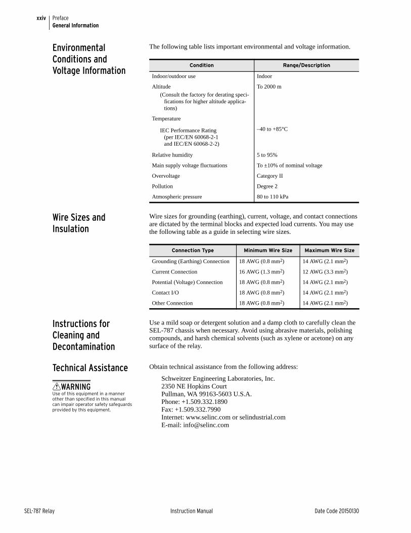
xxiv
SEL-787 Relay Instruction Manual Date Code 20150130
PrefaceGeneral Information
Environmental Conditions and Voltage Information
The following table lists important environmental and voltage information.
Wire Sizes and Insulation
Wire sizes for grounding (earthing), current, voltage, and contact connections are dictated by the terminal blocks and expected load currents. You may use the following table as a guide in selecting wire sizes.
Instructions for Cleaning and Decontamination
Use a mild soap or detergent solution and a damp cloth to carefully clean the SEL-787 chassis when necessary. Avoid using abrasive materials, polishing compounds, and harsh chemical solvents (such as xylene or acetone) on any surface of the relay.
Technical Assistance Obtain technical assistance from the following address:
Schweitzer Engineering Laboratories, Inc.2350 NE Hopkins CourtPullman, WA 99163-5603 U.S.A. Phone: +1.509.332.1890 Fax: +1.509.332.7990Internet: www.selinc.com or selindustrial.comE-mail: [email protected]
Condition Range/Description
Indoor/outdoor use Indoor
Altitude
(Consult the factory for derating speci-fications for higher altitude applica-tions)
To 2000 m
Temperature
IEC Performance Rating (per IEC/EN 60068-2-1 and IEC/EN 60068-2-2)
–40 to +85°C
Relative humidity 5 to 95%
Main supply voltage fluctuations To ±10% of nominal voltage
Overvoltage Category II
Pollution Degree 2
Atmospheric pressure 80 to 110 kPa
Connection Type Minimum Wire Size Maximum Wire Size
Grounding (Earthing) Connection 18 AWG (0.8 mm2) 14 AWG (2.1 mm2)
Current Connection 16 AWG (1.3 mm2) 12 AWG (3.3 mm2)
Potential (Voltage) Connection 18 AWG (0.8 mm2) 14 AWG (2.1 mm2)
Contact I/O 18 AWG (0.8 mm2) 14 AWG (2.1 mm2)
Other Connection 18 AWG (0.8 mm2) 14 AWG (2.1 mm2)
WARNINGUse of this equipment in a manner other than specified in this manual can impair operator safety safeguards provided by this equipment.
Date Code 20150130 Instruction Manual SEL-787 Relay
Section 1Introduction and Specifications
Instruction Manual
OverviewThe SEL-787 Transformer Protection Relay is designed to provide current differential and overcurrent protection to two-winding transformers, buses, generators, etc. The basic relay provides current differential and instantaneous and inverse time-overcurrent protection. Voltage-based and RTD-based protection are available as options. All relay models provide monitoring functions.
This manual contains the information needed to install, set, test, operate, and maintain any SEL-787. You need not review the entire manual to perform specific tasks.
For additional technical references on applications and testing (i.e., technical papers, application guides), visit www.selinc.com/literature/.
Features
Standard Protection Features
➤ Phase Instantaneous Overcurrent (50P)
➤ Ground (Residual) Instantaneous Overcurrent (50G)
➤ Negative-Sequence Overcurrent (50Q)
➤ Phase Time Overcurrent (51P)
➤ Ground (Residual) Time Overcurrent (51G)
➤ Negative-Sequence Time Overcurrent (51Q)
➤ Current Differential (87)
➤ Breaker Failure Protection
Optional Protection Features
➤ Voltage-Based Protection
➢ Undervoltage (27)
➢ Overvoltage (59)
➢ Negative-Sequence Overvoltage (59Q)
➢ Directional Power (32)
➢ Loss of Potential (60LOP)
➢ Frequency (81)
➢ Volts/Hertz (24)
1.2
SEL-787 Relay Instruction Manual Date Code 20150130
Introduction and SpecificationsModels, Options, and Accessories
➤ Neutral Current-Based Protection
➢ Neutral Instantaneous Overcurrent (50N)
➢ Neutral Time Overcurrent (51N)
➢ Restricted Earth Fault (REF)
➤ RTD-Based Protection: As many as ten (10) RTDs may be monitored when an internal RTD card is used, or as many as twelve (12) when an external SEL-2600 RTD Module with the ST® option (SEL-2812 compatible) is used. There are separate Trip and Warn settings for each RTD.
Monitoring Features ➤ Event Summaries that contain relay ID, date and time, trip cause, and current/voltage magnitudes
➤ Event Reports including filtered and raw analog data
➤ Sequential Events Record (SER)
➤ Compatibility with SEL-3010 Event Messenger
➤ Transformer Through-Fault Event Monitor
➤ A complete suite of accurate metering functions
Communications and Control ➤ EIA-232, front-panel port
➤ EIA-232, EIA-485, Ethernet (single/dual copper or fiber-optic), and SEL-2812 compatible ST fiber-optic rear-panel port
➤ IRIG-B time-code input
➤ Modbus® RTU slave, Modbus TCP/IP, DNP3 serial or LAN/WAN, Ethernet® FTP, Telnet, SNTP, MIRRORED BITS®, IEC 61850, DeviceNetTM, File Transfer Protocols, and Synchrophasors with C37.118 Protocol
➤ SEL ASCII, Compressed ASCII, Fast Meter, Fast Operate, Fast SER, Fast Message Protocols, and Event Messenger Protocol
➤ Programmable Boolean and math operators, logic functions, and analog compare
Models, Options, and Accessories
Models Complete ordering information is not provided in this instruction manual. See the latest SEL-787 Model Option Table at www.selinc.com, under SEL Literature, Ordering Information (Model Option Tables). Options and accessories are listed below.
SEL-787 Base Unit ➤ Front panel with large LCD display
➢ 4 programmable [buttons with 8 LEDs
➢ 8 target LEDs (6 programmable)
➢ Operator control interface
➢ EIA-232 port
1.3
Date Code 20150130 Instruction Manual SEL-787 Relay
Introduction and SpecificationsModels, Options, and Accessories
➤ Processor and communications card (Slot B)
➢ EIA-232 serial port with IRIG-B time code input
➢ Multimode (ST®) fiber-optic serial port (SEL-2812 compatible)
➢ EIA-485 serial port with external IRIG-B time code input (terminals B01, B02)
➤ Six ac current inputs card (Slot Z)
➤ Power supply card with two digital inputs and three digital outputs (Slot A)
➤ Three expansion slots for optional cards (Slots C, D, E)
➤ Protocols
➢ Modbus RTU
➢ SEL ASCII and Compressed ASCII
➢ SEL Fast Meter, Fast Operate, Fast SER, Fast Message
➢ Ymodem File Transfer
➢ SEL MIRRORED BITS
➢ Event Messenger®
➢ Synchrophasors with C37.118
Options ➤ Neutral AC Current Option (1 A or 5 A neutral)
➤ Voltage Option
➢ Four-wire wye
➢ Open-delta
➢ Single phase connected
➤ Input/Output (I/O) Option
➢ Additional digital I/O
➢ Additional analog I/O
➢ 10 RTD inputs
➤ Communications Options (Protocol/Ports)
➢ EIA-485/EIA-232/Ethernet ports (single/dual copper or fiber-optic)
➢ Modbus TCP/IP
➢ DeviceNet
➢ IEC 61850 Communications
➢ DNP3 serial and LAN/WAN
➢ Simple Network Time Protocol (SNTP)
Accessories Contact your Technical Service Center or the SEL factory for additional detail and ordering information for the following accessories:
➤ External RTD protection
➢ SEL-2600 RTD Module (with ST option only)
➢ A simplex 62.5/125 µm fiber-optic cable with ST connector for connecting the external RTD module to the SEL-787
➤ Remote I/O with SEL-2505 Remote I/O Module (SEL-2812 compatible ST option only)
1.4
SEL-787 Relay Instruction Manual Date Code 20150130
Introduction and SpecificationsApplications
➤ SEL-787 Configurable Labels
➤ Rack-Mounting Kits
➢ For one relay
➢ For two relays
➢ For one relay and a test switch
➤ Wall-Mounting Kits
➤ Bezels for Retrofit
➤ Replacement Rear Connector Kit
For all SEL-787 mounting accessories for competitor products’ replacement, including adapter plates, visit http://www.selinc.com/MountingAccessories.
ApplicationsRefer to Section 2: Installation for various applications and their related connection diagrams. The following is a list of possible application scenarios:
➤ Two-winding transformer protection with current differential and overcurrent elements and through-fault monitor
➤ Two-winding transformer protection with current differential and overcurrent elements and through-fault monitor with optional restricted earth fault protection (REF) and neutral-overcurrent protection
➤ Two-winding transformer protection with current differential and overcurrent elements and through-fault monitor with optional voltage elements, power elements, and frequency elements
➤ Two-winding transformer protection with current differential and overcurrent elements and through-fault monitor with optional internal or external RTD inputs module
Getting Started
IMPORTANT: Upon relay initial power up or Port 1 setting changes or Logic setting changes, the user may have to wait as long as two minutes before an additional setting change can occur. Note that the relay is functional with protection enabled, as soon as the ENABLED LED comes ON (about 5–10 seconds from power up).
Understanding basic relay operation principles and methods will help you use the SEL-787 effectively. This section presents the fundamental knowledge you need to operate the SEL-787, organized by task. These tasks help you become familiar with the relay and include the following:
➤ Powering the relay
➤ Establishing communication
➤ Checking relay status
➤ Setting the date and time
Perform these tasks to gain a fundamental understanding of relay operation.
Powering the Relay Power the SEL-787 with 125/250 Vac/dc or 24/48 Vdc, depending on the part number.
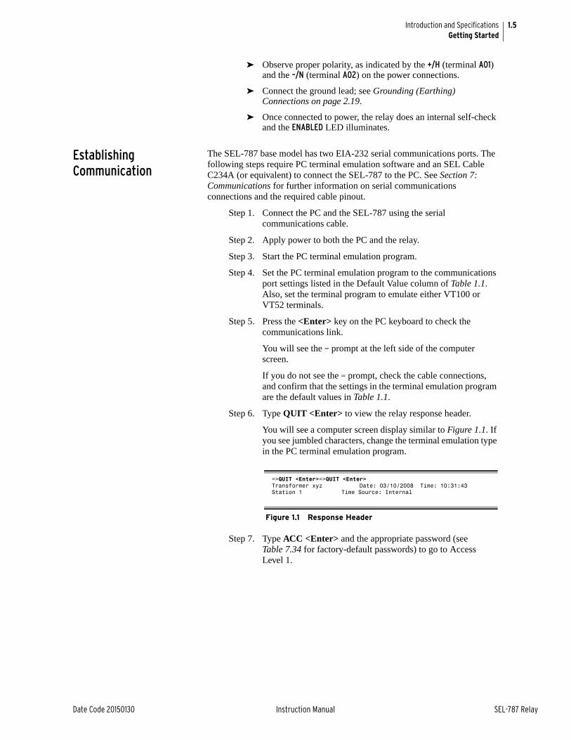
1.5
Date Code 20150130 Instruction Manual SEL-787 Relay
Introduction and SpecificationsGetting Started
➤ Observe proper polarity, as indicated by the +/H (terminal A01) and the –/N (terminal A02) on the power connections.
➤ Connect the ground lead; see Grounding (Earthing) Connections on page 2.19.
➤ Once connected to power, the relay does an internal self-check and the ENABLED LED illuminates.
Establishing Communication
The SEL-787 base model has two EIA-232 serial communications ports. The following steps require PC terminal emulation software and an SEL Cable C234A (or equivalent) to connect the SEL-787 to the PC. See Section 7: Communications for further information on serial communications connections and the required cable pinout.
Step 1. Connect the PC and the SEL-787 using the serial communications cable.
Step 2. Apply power to both the PC and the relay.
Step 3. Start the PC terminal emulation program.
Step 4. Set the PC terminal emulation program to the communications port settings listed in the Default Value column of Table 1.1. Also, set the terminal program to emulate either VT100 or VT52 terminals.
Step 5. Press the <Enter> key on the PC keyboard to check the communications link.
You will see the = prompt at the left side of the computer screen.
If you do not see the = prompt, check the cable connections, and confirm that the settings in the terminal emulation program are the default values in Table 1.1.
Step 6. Type QUIT <Enter> to view the relay response header.
You will see a computer screen display similar to Figure 1.1. If you see jumbled characters, change the terminal emulation type in the PC terminal emulation program.
Step 7. Type ACC <Enter> and the appropriate password (see Table 7.34 for factory-default passwords) to go to Access Level 1.
=>QUIT <Enter>=>QUIT <Enter>Transformer xyz Date: 03/10/2008 Time: 10:31:43Station 1 Time Source: Internal
Figure 1.1 Response Header
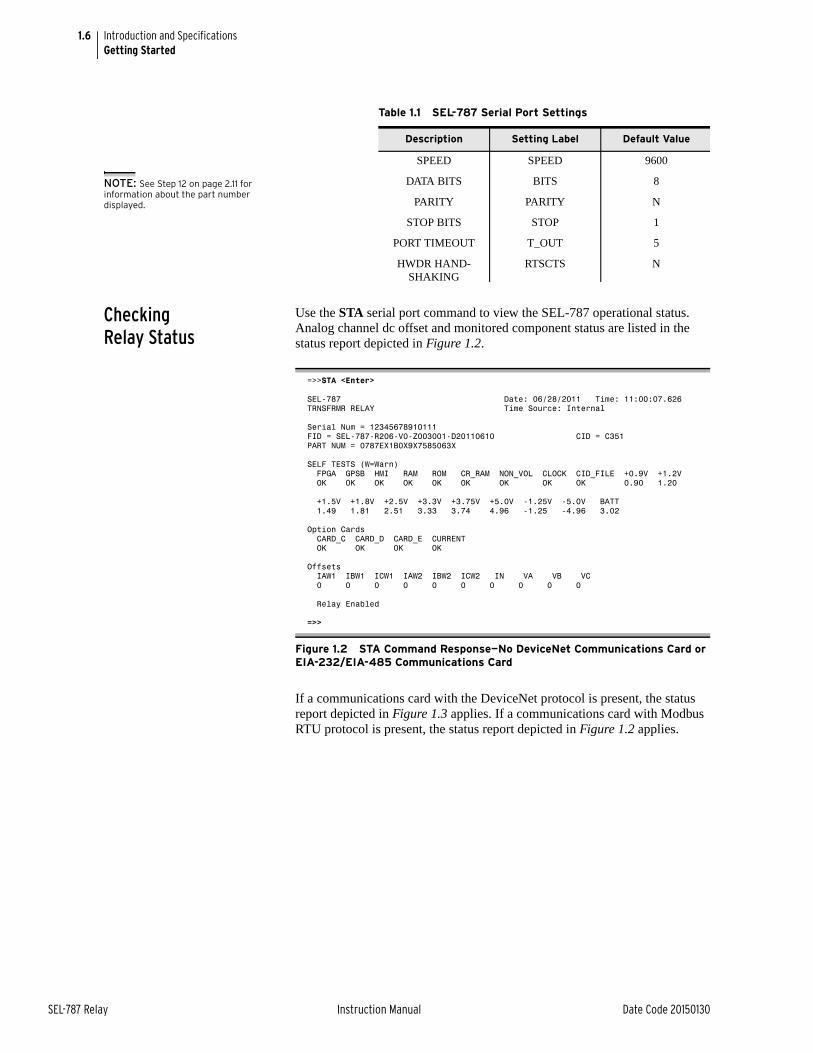
1.6
SEL-787 Relay Instruction Manual Date Code 20150130
Introduction and SpecificationsGetting Started
Checking Relay Status
Use the STA serial port command to view the SEL-787 operational status. Analog channel dc offset and monitored component status are listed in the status report depicted in Figure 1.2.
If a communications card with the DeviceNet protocol is present, the status report depicted in Figure 1.3 applies. If a communications card with Modbus RTU protocol is present, the status report depicted in Figure 1.2 applies.
Table 1.1 SEL-787 Serial Port Settings
Description Setting Label Default Value
SPEED SPEED 9600
DATA BITS BITS 8
PARITY PARITY N
STOP BITS STOP 1
PORT TIMEOUT T_OUT 5
HWDR HAND-SHAKING
RTSCTS N
=>>STA <Enter>
SEL-787 Date: 06/28/2011 Time: 11:00:07.626TRNSFRMR RELAY Time Source: Internal
Serial Num = 12345678910111FID = SEL-787-R206-V0-Z003001-D20110610 CID = C351PART NUM = 0787EX1B0X9X7585063X
SELF TESTS (W=Warn) FPGA GPSB HMI RAM ROM CR_RAM NON_VOL CLOCK CID_FILE +0.9V +1.2V OK OK OK OK OK OK OK OK OK 0.90 1.20
+1.5V +1.8V +2.5V +3.3V +3.75V +5.0V -1.25V -5.0V BATT 1.49 1.81 2.51 3.33 3.74 4.96 -1.25 -4.96 3.02
Option Cards CARD_C CARD_D CARD_E CURRENT OK OK OK OK
Offsets IAW1 IBW1 ICW1 IAW2 IBW2 ICW2 IN VA VB VC 0 0 0 0 0 0 0 0 0 0
Relay Enabled
=>>
Figure 1.2 STA Command Response—No DeviceNet Communications Card or EIA-232/EIA-485 Communications Card
NOTE: See Step 12 on page 2.11 for information about the part number displayed.
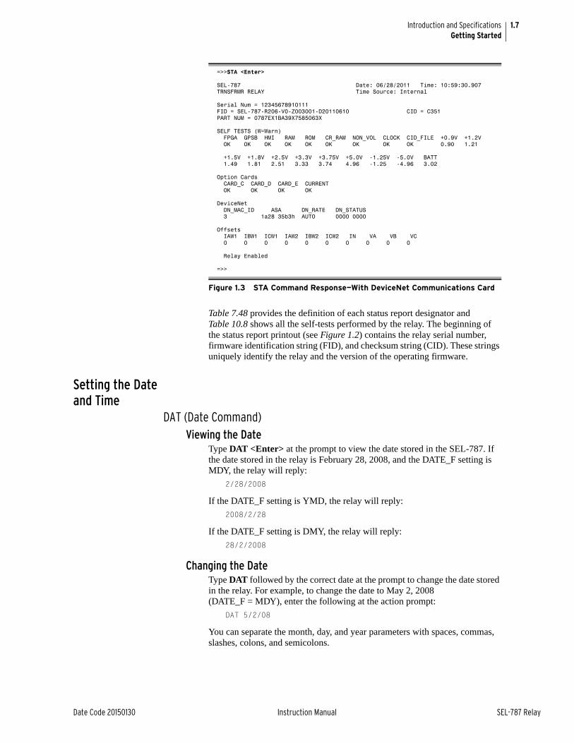
1.7
Date Code 20150130 Instruction Manual SEL-787 Relay
Introduction and SpecificationsGetting Started
Table 7.48 provides the definition of each status report designator and Table 10.8 shows all the self-tests performed by the relay. The beginning of the status report printout (see Figure 1.2) contains the relay serial number, firmware identification string (FID), and checksum string (CID). These strings uniquely identify the relay and the version of the operating firmware.
Setting the Date and Time
DAT (Date Command)Viewing the Date
Type DAT <Enter> at the prompt to view the date stored in the SEL-787. If the date stored in the relay is February 28, 2008, and the DATE_F setting is MDY, the relay will reply:
2/28/2008
If the DATE_F setting is YMD, the relay will reply:
2008/2/28
If the DATE_F setting is DMY, the relay will reply:
28/2/2008
Changing the DateType DAT followed by the correct date at the prompt to change the date stored in the relay. For example, to change the date to May 2, 2008 (DATE_F = MDY), enter the following at the action prompt:
DAT 5/2/08
You can separate the month, day, and year parameters with spaces, commas, slashes, colons, and semicolons.
=>>STA <Enter>
SEL-787 Date: 06/28/2011 Time: 10:59:30.907TRNSFRMR RELAY Time Source: Internal
Serial Num = 12345678910111FID = SEL-787-R206-V0-Z003001-D20110610 CID = C351PART NUM = 0787EX1BA39X7585063X
SELF TESTS (W=Warn) FPGA GPSB HMI RAM ROM CR_RAM NON_VOL CLOCK CID_FILE +0.9V +1.2V OK OK OK OK OK OK OK OK OK 0.90 1.21
+1.5V +1.8V +2.5V +3.3V +3.75V +5.0V -1.25V -5.0V BATT 1.49 1.81 2.51 3.33 3.74 4.96 -1.25 -4.96 3.02
Option Cards CARD_C CARD_D CARD_E CURRENT OK OK OK OK
DeviceNet DN_MAC_ID ASA DN_RATE DN_STATUS 3 1a28 35b3h AUTO 0000 0000
Offsets IAW1 IBW1 ICW1 IAW2 IBW2 ICW2 IN VA VB VC 0 0 0 0 0 0 0 0 0 0
Relay Enabled
=>>
Figure 1.3 STA Command Response—With DeviceNet Communications Card
1.8
SEL-787 Relay Instruction Manual Date Code 20150130
Introduction and SpecificationsGetting Started
TIM (Time Command)Viewing the Time
Enter TIM at the prompt to view the time stored in the SEL-787. The relay will reply with the stored time:
13:52:44
This time is 1:52 p.m. (and 44 seconds).
Changing the TimeEnter TIM followed by the correct time at the action prompt to change the time stored in the relay. For example, to change the time to 6:32 a.m., enter the following at the prompt:
TIM 6:32:00
You can separate the hours, minutes, and seconds parameters with spaces, commas, slashes, colons, and semicolons.
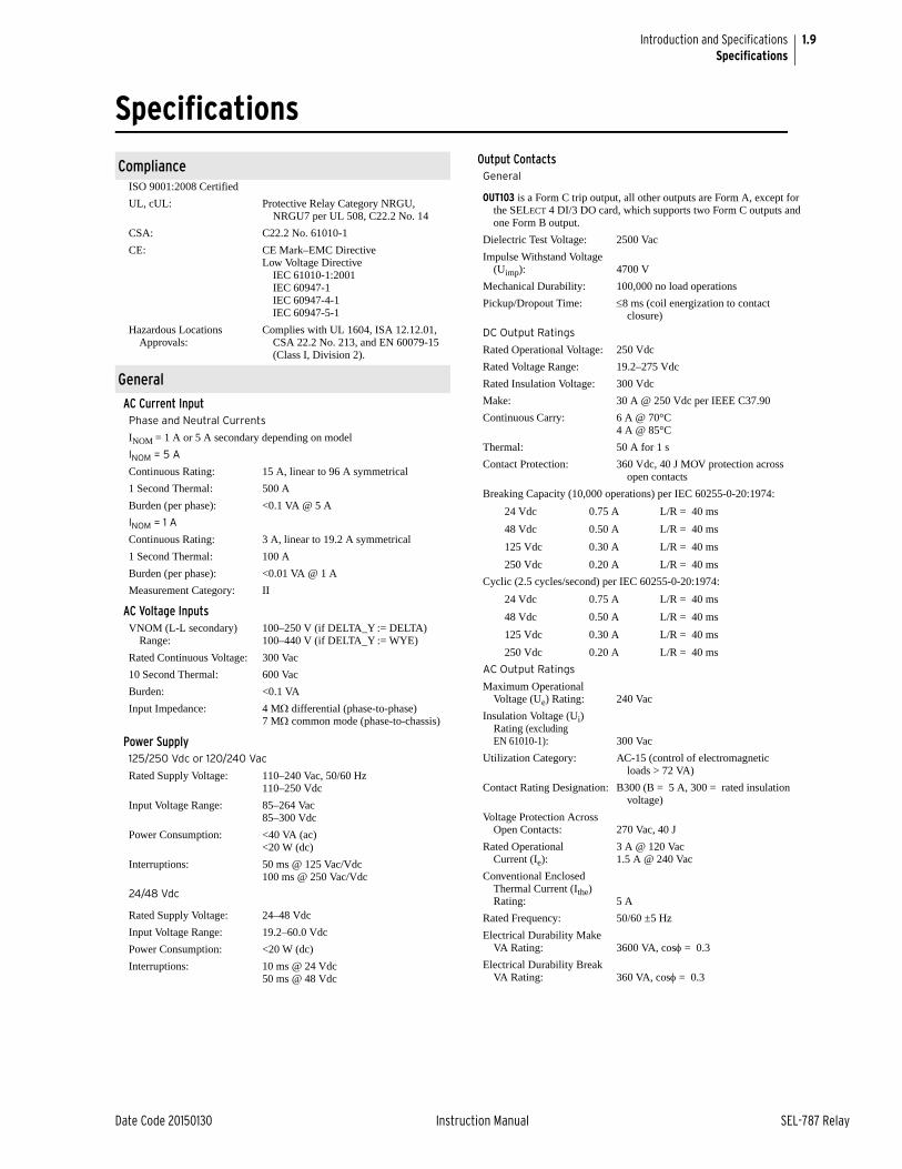
1.9
Date Code 20150130 Instruction Manual SEL-787 Relay
Introduction and SpecificationsSpecifications
SpecificationsInstruction Manual
ComplianceISO 9001:2008 Certified
UL, cUL: Protective Relay Category NRGU, NRGU7 per UL 508, C22.2 No. 14
CSA: C22.2 No. 61010-1
CE: CE Mark–EMC DirectiveLow Voltage Directive
IEC 61010-1:2001IEC 60947-1IEC 60947-4-1IEC 60947-5-1
Hazardous Locations Approvals:
Complies with UL 1604, ISA 12.12.01, CSA 22.2 No. 213, and EN 60079-15 (Class I, Division 2).
General
AC Current InputPhase and Neutral Currents
INOM = 1 A or 5 A secondary depending on model
INOM = 5 A
Continuous Rating: 15 A, linear to 96 A symmetrical
1 Second Thermal: 500 A
Burden (per phase): <0.1 VA @ 5 A
INOM = 1 A
Continuous Rating: 3 A, linear to 19.2 A symmetrical
1 Second Thermal: 100 A
Burden (per phase): <0.01 VA @ 1 A
Measurement Category: II
AC Voltage InputsVNOM (L-L secondary)
Range:100–250 V (if DELTA_Y := DELTA)100–440 V (if DELTA_Y := WYE)
Rated Continuous Voltage: 300 Vac
10 Second Thermal: 600 Vac
Burden: <0.1 VA
Input Impedance: 4 M differential (phase-to-phase)7 M common mode (phase-to-chassis)
Power Supply125/250 Vdc or 120/240 Vac
Rated Supply Voltage: 110–240 Vac, 50/60 Hz110–250 Vdc
Input Voltage Range: 85–264 Vac85–300 Vdc
Power Consumption: <40 VA (ac)<20 W (dc)
Interruptions: 50 ms @ 125 Vac/Vdc100 ms @ 250 Vac/Vdc
24/48 Vdc
Rated Supply Voltage: 24–48 Vdc
Input Voltage Range: 19.2–60.0 Vdc
Power Consumption: <20 W (dc)
Interruptions: 10 ms @ 24 Vdc50 ms @ 48 Vdc
Output ContactsGeneral
OUT103 is a Form C trip output, all other outputs are Form A, except for the SELECT 4 DI/3 DO card, which supports two Form C outputs and one Form B output.
Dielectric Test Voltage: 2500 Vac
Impulse Withstand Voltage (Uimp): 4700 V
Mechanical Durability: 100,000 no load operations
Pickup/Dropout Time: 8 ms (coil energization to contact closure)
DC Output Ratings
Rated Operational Voltage: 250 Vdc
Rated Voltage Range: 19.2–275 Vdc
Rated Insulation Voltage: 300 Vdc
Make: 30 A @ 250 Vdc per IEEE C37.90
Continuous Carry: 6 A @ 70°C4 A @ 85°C
Thermal: 50 A for 1 s
Contact Protection: 360 Vdc, 40 J MOV protection across open contacts
Breaking Capacity (10,000 operations) per IEC 60255-0-20:1974:
24 Vdc 0.75 A L/R = 40 ms
48 Vdc 0.50 A L/R = 40 ms
125 Vdc 0.30 A L/R = 40 ms
250 Vdc 0.20 A L/R = 40 ms
Cyclic (2.5 cycles/second) per IEC 60255-0-20:1974:
24 Vdc 0.75 A L/R = 40 ms
48 Vdc 0.50 A L/R = 40 ms
125 Vdc 0.30 A L/R = 40 ms
250 Vdc 0.20 A L/R = 40 ms
AC Output Ratings
Maximum Operational Voltage (Ue) Rating: 240 Vac
Insulation Voltage (Ui) Rating (excluding EN 61010-1): 300 Vac
Utilization Category: AC-15 (control of electromagnetic loads > 72 VA)
Contact Rating Designation: B300 (B = 5 A, 300 = rated insulation voltage)
Voltage Protection Across Open Contacts: 270 Vac, 40 J
Rated Operational Current (Ie):
3 A @ 120 Vac1.5 A @ 240 Vac
Conventional Enclosed Thermal Current (Ithe) Rating: 5 A
Rated Frequency: 50/60 ±5 Hz
Electrical Durability Make VA Rating: 3600 VA, cos = 0.3
Electrical Durability Break VA Rating: 360 VA, cos = 0.3

1.10
SEL-787 Relay Instruction Manual Date Code 20150130
Introduction and SpecificationsSpecifications
Fast Hybrid (High-Speed High-Current Interrupting)
Make: 30 A
Carry: 6 A continuous carry at 70°C4 A continuous carry at 85°C
1 s Rating: 50 A
Open State Leakage Current: <100 µA
MOV Protection (maximum voltage): 250 Vac/330 Vdc
Pickup Time: <50 s, resistive load
Dropout Time: 8 ms, resistive load
Update Rate: 1/8 cycle
Break Capacity (10000 operations):
48 Vdc 10.0 A L/R = 40 ms
125 Vdc 10.0 A L/R = 40 ms
250 Vdc 10.0 A L/R = 20 ms
Cyclic Capacity (4 cycles in 1 second, followed by 2 minutes idle for thermal dissipation):
48 Vdc 10.0 A L/R = 40 ms
125 Vdc 10.0 A L/R = 40 ms
250 Vdc 10.0 A L/R = 20 ms
NOTE: Per IEC 60255-23:1994, using the simplified method of assessment.NOTE: Make rating per IEEE C37.90-1989.
Optoisolated Control InputsWhen Used With DC Control Signals
250 V: ON for 200–312.5 VdcOFF below 150 Vdc
220 V: ON for 176–275 VdcOFF below 132 Vdc
125 V: ON for 100–156.2 VdcOFF below 75 Vdc
110 V: ON for 88–137.5 VdcOFF below 66 Vdc
48 V: ON for 38.4–60 VdcOFF below 28.8 Vdc
24 V: ON for 15–30 VdcOFF for <5 Vdc
When Used With AC Control Signals
250 V: ON for 170.6–312.5 VacOFF below 106 Vac
220 V: ON for 150.2–275 VacOFF below 93.3 Vac
125 V: ON for 85–156.2 VacOFF below 53 Vac
110 V: ON for 75.1–137.5 VacOFF below 46.6 Vac
48 V: ON for 32.8–60 VacOFF below 20.3 Vac
24 V: ON for 14–30 VacOFF below 5 Vac
Current draw at nominal dc voltage:
2 mA (at 220–250 V)4 mA (at 48–125 V)10 mA (at 24 V)
Rated Impulse Withstand Voltage (Uimp): 4000 V
UL/CSA Digital Output Contact Temperature Derating for Operating at Elevated Temperatures
Digital Output Cards Installed
Operating Ambient
Maximum Value of Current (Ithe) Duty Factor
1–3 less than or equal to 60°C
5.0 A Continuous
1–3 between 60°C and 70°C
2.5 A Continuous
Analog Output (Optional)1A0 4A0
Current: 4–20 mA ±20 mA
Voltage: — ±10 V
Load at 1 mA: — 0–15 kLoad at 20 mA: 0–300 0–750 Load at 10 V: — >2000 Refresh Rate: 100 ms 100 ms
% Error, Full Scale, at 25°C: <±1% <±0.55%
Select From: Analog quantities available in the relay
Analog Inputs (Optional)Maximum Input Range: ±20 mA
±10 VOperational range set by user
Input Impedance: 200 (current mode)>10 k (voltage mode)
Accuracy at 25°C:
With user calibration: 0.05% of full scale (current mode)0.025% of full scale (voltage mode)
Without user calibration: Better than 0.5% of full scale at 25°C
Accuracy Variation With Temperature:
±0.015% per °C of full-scale (±20 mA or ±10 V)
Frequency and Phase RotationSystem Frequency: 50, 60 Hz
Phase Rotation: ABC, ACB
Frequency Tracking: 20–70 Hz (requires ac voltage inputs option)
Time-Code InputFormat: Demodulated IRIG-B
On (1) State: Vih 2.2 V
Off (0) State: Vil 0.8 V
Input Impedance: 2 k
Synchronization Accuracy:
Internal Clock: ±1 µs
Synchrophasor Reports(e.g., MET PM ): ±10 µs
All Other Reports: ±5 ms
Simple Network Time Protocol (SNTP) Accuracy
Internal Clock: ±5 ms
Unsynchronized Clock Drift Relay Powered: 2 minutes per year, typically
Communications PortsStandard EIA-232 (2 ports)
Location: Front PanelRear Panel
Data Speed: 300–38400 bps
EIA-485 Port (optional)
Location: Rear Panel
Data Speed: 300–19200 bps
Ethernet Port (optional)
Single/Dual 10/100BASE-T copper (RJ45 connector)Single/Dual 100BASE-FX (LC connector)
Standard Multimode Fiber-Optic Port
Location: Front Panel
Data Speed: 300–38400 bps
Fiber-Optic Ports CharacteristicsPort 1 (or 1A, 1B) Ethernet
Wavelength: 1300 nm
Optical Connector Type: LC
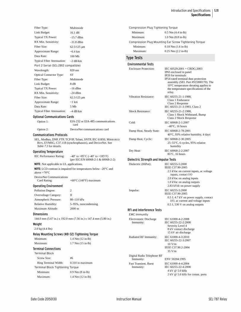
1.11
Date Code 20150130 Instruction Manual SEL-787 Relay
Introduction and SpecificationsSpecifications
Fiber Type: Multimode
Link Budget: 16.1 dB
Typical TX Power: –15.7 dBm
RX Min. Sensitivity: –31.8 dBm
Fiber Size: 62.5/125 µm
Approximate Range: ~6.4 km
Data Rate: 100 Mb
Typical Fiber Attenuation: –2 dB/km
Port 2 Serial (SEL-2812 compatible)
Wavelength: 820 nm
Optical Connector Type: ST
Fiber Type: Multimode
Link Budget: 8 dB
Typical TX Power: –16 dBm
RX Min. Sensitivity: –24 dBm
Fiber Size: 62.5/125 µm
Approximate Range: ~1 km
Data Rate: 5 Mb
Typical Fiber Attenuation: –4 dB/km
Optional Communications CardsOption 1: EIA-232 or EIA-485 communications
card
Option 2: DeviceNet communications card
Communications ProtocolsSEL, Modbus, DNP, FTP, TCP/IP, Telnet, SNTP, IEC 61850, MIRRORED
BITS, EVMSG, C37.118 (synchrophasors), and DeviceNet. See Table 7.3 for details.
Operating TemperatureIEC Performance Rating: –40 to +85C (–40 to +185F)
(per IEC/EN 60068-2-1 & 60068-2-2)
NOTE: Not applicable to UL applications.
NOTE: LCD contrast is impaired for temperatures below –20°C and above +70°C
DeviceNet Communications Card Rating: +60°C (140°F) maximum
Operating EnvironmentPollution Degree: 2
Overvoltage Category: II
Atmospheric Pressure: 80–110 kPa
Relative Humidity: 5–95%, noncondensing
Maximum Altitude: 2000 m
Dimensions144.0 mm (5.67 in.) x 192.0 mm (7.56 in.) x 147.4 mm (5.80 in.)
Weight2.0 kg (4.4 lbs)
Relay Mounting Screws (#8–32) Tightening TorqueMinimum: 1.4 Nm (12 in-lb)
Maximum: 1.7 Nm (15 in-lb)
Terminal ConnectionsTerminal Block
Screw Size: #6
Ring Terminal Width: 0.310 in maximum
Terminal Block Tightening Torque
Minimum: 0.9 Nm (8 in-lb)
Maximum: 1.4 Nm (12 in-lb)
Compression Plug Tightening Torque
Minimum: 0.5 Nm (4.4 in-lb)
Maximum: 1.0 Nm (8.8 in-lb)
Compression Plug Mounting Ear Screw Tightening Torque
Minimum: 0.18 Nm (1.6 in-lb)
Maximum: 0.25 Nm (2.2 in-lb)
Type Tests
Environmental TestsEnclosure Protection: IEC 60529:2001 + CRDG:2003
IP65 enclosed in panelIP20 for terminalsIP54-rated terminal dust protection
assembly (SEL Part #915900170). The 10°C temperature derating applies to the temperature specifications of the relay.
Vibration Resistance: IEC 60255-21-1:1988, Class 1 EnduranceClass 2 Response
IEC 60255-21-3:1993, Class 2
Shock Resistance: IEC 60255-21-2:1988, Class 1 Shock Withstand, BumpClass 2 Shock Response
Cold: IEC 60068-2-1:2007–40°C, 16 hours
Damp Heat, Steady State: IEC 60068-2-78:200140°C, 93% relative humidity, 4 days
Damp Heat, Cyclic: IEC 60068-2-30:200525–55°C, 6 cycles, 95% relative
humidity
Dry Heat: IEC 60068-2-2:200785°C, 16 hours
Dielectric Strength and Impulse TestsDielectric (HiPot): IEC 60255-5:2000
IEEE C37.90-20052.5 kVac on current inputs, ac voltage
inputs, contact I/O2.0 kVac on analog inputs1.0 kVac on analog outputs2.83 kVdc on power supply
Impulse: IEC 60255-5:2000IEEE C37.90-2005
0.5 J, 4.7 kV on power supply, contactI/O, ac current and voltage inputs
0.5 J, 530 V on analog outputs
RFI and Interference TestsEMC Immunity
Electrostatic Discharge Immunity:
IEC 61000-4-2:2008IEC 60255-22-2:2008
Severity Level 48 kV contact discharge15 kV air discharge
Radiated RF Immunity: IEC 61000-4-3:2010IEC 60255-22-3:2007
10 V/mIEEE C37.90.2-2004
35 V/m
Digital Radio Telephone RF Immunity: ENV 50204:1995
Fast Transient, Burst Immunity:
IEC 61000-4-4:2004IEC 60255-22-4:2008
4 kV @ 5.0 kHz2 kV @ 5.0 kHz for comm. ports
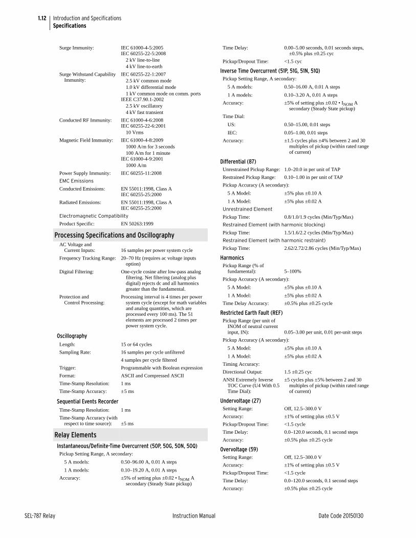
1.12
SEL-787 Relay Instruction Manual Date Code 20150130
Introduction and SpecificationsSpecifications
Surge Immunity: IEC 61000-4-5:2005IEC 60255-22-5:2008
2 kV line-to-line4 kV line-to-earth
Surge Withstand Capability Immunity:
IEC 60255-22-1:20072.5 kV common mode1.0 kV differential mode1 kV common mode on comm. ports
IEEE C37.90.1-20022.5 kV oscillatory4 kV fast transient
Conducted RF Immunity: IEC 61000-4-6:2008IEC 60255-22-6:2001
10 Vrms
Magnetic Field Immunity: IEC 61000-4-8:20091000 A/m for 3 seconds100 A/m for 1 minute
IEC 61000-4-9:20011000 A/m
Power Supply Immunity: IEC 60255-11:2008
EMC Emissions
Conducted Emissions: EN 55011:1998, Class AIEC 60255-25:2000
Radiated Emissions: EN 55011:1998, Class A IEC 60255-25:2000
Electromagnetic Compatibility
Product Specific: EN 50263:1999
Processing Specifications and OscillographyAC Voltage and
Current Inputs: 16 samples per power system cycle
Frequency Tracking Range: 20–70 Hz (requires ac voltage inputs option)
Digital Filtering: One-cycle cosine after low-pass analog filtering. Net filtering (analog plus digital) rejects dc and all harmonics greater than the fundamental.
Protection and Control Processing:
Processing interval is 4 times per power system cycle (except for math variables and analog quantities, which are processed every 100 ms). The 51 elements are processed 2 times per power system cycle.
OscillographyLength: 15 or 64 cycles
Sampling Rate: 16 samples per cycle unfiltered
4 samples per cycle filtered
Trigger: Programmable with Boolean expression
Format: ASCII and Compressed ASCII
Time-Stamp Resolution: 1 ms
Time-Stamp Accuracy: ±5 ms
Sequential Events RecorderTime-Stamp Resolution: 1 ms
Time-Stamp Accuracy (with respect to time source): ±5 ms
Relay Elements
Instantaneous/Definite-Time Overcurrent (50P, 50G, 50N, 50Q)Pickup Setting Range, A secondary:
5 A models: 0.50–96.00 A, 0.01 A steps
1 A models: 0.10–19.20 A, 0.01 A steps
Accuracy: ±5% of setting plus ±0.02 • INOM A secondary (Steady State pickup)
Time Delay: 0.00–5.00 seconds, 0.01 seconds steps, ±0.5% plus ±0.25 cyc
Pickup/Dropout Time: <1.5 cyc
Inverse Time Overcurrent (51P, 51G, 51N, 51Q)Pickup Setting Range, A secondary:
5 A models: 0.50–16.00 A, 0.01 A steps
1 A models: 0.10–3.20 A, 0.01 A steps
Accuracy: ±5% of setting plus ±0.02 • INOM A secondary (Steady State pickup)
Time Dial:
US: 0.50–15.00, 0.01 steps
IEC: 0.05–1.00, 0.01 steps
Accuracy: ±1.5 cycles plus ±4% between 2 and 30 multiples of pickup (within rated range of current)
Differential (87)Unrestrained Pickup Range: 1.0–20.0 in per unit of TAP
Restrained Pickup Range: 0.10–1.00 in per unit of TAP
Pickup Accuracy (A secondary):
5 A Model: ±5% plus ±0.10 A
1 A Model: ±5% plus ±0.02 A
Unrestrained Element
Pickup Time: 0.8/1.0/1.9 cycles (Min/Typ/Max)
Restrained Element (with harmonic blocking)
Pickup Time: 1.5/1.6/2.2 cycles (Min/Typ/Max)
Restrained Element (with harmonic restraint)
Pickup Time: 2.62/2.72/2.86 cycles (Min/Typ/Max)
HarmonicsPickup Range (% of
fundamental): 5–100%
Pickup Accuracy (A secondary):
5 A Model: ±5% plus ±0.10 A
1 A Model: ±5% plus ±0.02 A
Time Delay Accuracy: ±0.5% plus ±0.25 cycle
Restricted Earth Fault (REF)Pickup Range (per unit of
INOM of neutral current input, IN): 0.05–3.00 per unit, 0.01 per-unit steps
Pickup Accuracy (A secondary):
5 A Model: ±5% plus ±0.10 A
1 A Model: ±5% plus ±0.02 A
Timing Accuracy:
Directional Output: 1.5 ±0.25 cyc
ANSI Extremely Inverse TOC Curve (U4 With 0.5 Time Dial):
±5 cycles plus ±5% between 2 and 30 multiples of pickup (within rated range of current)
Undervoltage (27)Setting Range: Off, 12.5–300.0 V
Accuracy: ±1% of setting plus ±0.5 V
Pickup/Dropout Time: <1.5 cycle
Time Delay: 0.0–120.0 seconds, 0.1 second steps
Accuracy: ±0.5% plus ±0.25 cycle
Overvoltage (59)Setting Range: Off, 12.5–300.0 V
Accuracy: ±1% of setting plus ±0.5 V
Pickup/Dropout Time: <1.5 cycle
Time Delay: 0.0–120.0 seconds, 0.1 second steps
Accuracy: ±0.5% plus ±0.25 cycle
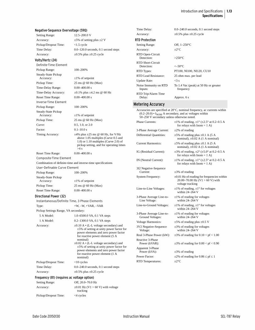
1.13
Date Code 20150130 Instruction Manual SEL-787 Relay
Introduction and SpecificationsSpecifications
Negative-Sequence Overvoltage (59Q)Setting Range: 12.5–200.0 V
Accuracy: ±5% of setting plus ±2 V
Pickup/Dropout Time: <1.5 cycle
Time Delay: 0.0–120.0 seconds, 0.1 second steps
Accuracy: ±0.5% plus ±0.25 cycle
Volts/Hertz (24)Definite-Time Element
Pickup Range: 100–200%
Steady-State Pickup Accuracy: ±1% of setpoint
Pickup Time: 25 ms @ 60 Hz (Max)
Time-Delay Range: 0.00–400.00 s
Time-Delay Accuracy: ±0.1% plus ±4.2 ms @ 60 Hz
Reset Time Range: 0.00–400.00 s
Inverse-Time Element
Pickup Range: 100–200%
Steady-State Pickup Accuracy: ±1% of setpoint
Pickup Time: 25 ms @ 60 Hz (Max)
Curve: 0.5, 1.0, or 2.0
Factor: 0.1–10.0 s
Timing Accuracy: ±4% plus ±25 ms @ 60 Hz, for V/Hz above 1.05 multiples (Curve 0.5 and 1.0) or 1.10 multiples (Curve 2.0) of pickup setting, and for operating times >4 s
Reset Time Range: 0.00–400.00 s
Composite-Time Element
Combination of definite-time and inverse-time specifications
User-Definable Curve Element
Pickup Range: 100–200%
Steady-State Pickup Accuracy: ±1% of setpoint
Pickup Time: 25 ms @ 60 Hz (Max)
Reset Time Range: 0.00–400.00 s
Directional Power (32)Instantaneous/Definite Time, 3 Phase Elements
Type: +W, –W, +VAR, –VAR
Pickup Settings Range, VA secondary:
5 A Model: 1.0–6500.0 VA, 0.1 VA steps
1 A Model: 0.2–1300.0 VA, 0.1 VA steps
Accuracy: ±0.10 A • (L-L voltage secondary) and ±5% of setting at unity power factor for power elements and zero power factor for reactive power element (5 A nominal)
±0.02 A • (L-L voltage secondary) and ±5% of setting at unity power factor for power elements and zero power factor for reactive power element (1 A nominal)
Pickup/Dropout Time: <10 cycles
Time Delay: 0.0–240.0 seconds, 0.1 second steps
Accuracy: ±0.5% plus ±0.25 cycle
Frequency (81) (requires ac voltage option)Setting Range: Off, 20.0–70.0 Hz
Accuracy: ±0.01 Hz (V1 > 60 V) with voltage tracking
Pickup/Dropout Time: <4 cycles
Time Delay: 0.0–240.0 seconds, 0.1 second steps
Accuracy: ±0.5% plus ±0.25 cycle
RTD ProtectionSetting Range: Off, 1–250°C
Accuracy: ±2CRTD Open-Circuit
Detection: >250°C
RTD Short-Circuit Detection: <–50°C
RTD Types: PT100, NI100, NI120, CU10
RTD Lead Resistance: 25 ohm max. per lead
Update Rate: <3 s
Noise Immunity on RTD Inputs:
To 1.4 Vac (peak) at 50 Hz or greater frequency
RTD Trip/Alarm Time Delay: Approx. 6 s
Metering AccuracyAccuracies are specified at 20C, nominal frequency, ac currents within
(0.2–20.0) • INOM A secondary, and ac voltages within 50–250 V secondary unless otherwise noted.
Phase Currents: ±1% of reading, ±1° (±2.5° at 0.2–0.5 A for relays with Inom = 1 A)
3-Phase Average Current: ±2% of reading
Differential Quantities: ±5% of reading plus ±0.1 A (5 A nominal), ±0.02 A (1 A nominal)
Current Harmonics: ±5% of reading plus ±0.1 A (5 A nominal), ±0.02 A (1 A nominal)
IG (Residual Current): ±3% of reading, ±2° (±5.0° at 0.2–0.5 A for relays with Inom = 1 A)
IN (Neutral Current): ±1% of reading, ±1° (±2.5° at 0.2–0.5 A for relays with Inom = 1 A)
3I2 Negative-Sequence Current: ±3% of reading
System Frequency: ±0.01 Hz of reading for frequencies within 20.00–70.00 Hz (V1 > 60 V) with voltage tracking
Line-to-Line Voltages: ±1% of reading, ±1° for voltages within 24–264 V
3-Phase Average Line-to-Line Voltage:
±1% of reading for voltages within 24–264 V
Line-to-Ground Voltages: ±1% of reading, ±1° for voltages within 24–264 V
3-Phase Average Line-to-Ground Voltages:
±1% of reading for voltages within 24–264 V
Voltage Harmonics: ±5% of reading plus ±0.5 V
3V2 Negative-Sequence Voltage:
±3% of reading for voltages within 24–264 V
Real 3-Phase Power (kW): ±3% of reading for 0.10 < pf < 1.00
Reactive 3-Phase Power (kVAR): ±3% of reading for 0.00 < pf < 0.90
Apparent 3-Phase Power (kVA): ±3% of reading
Power Factor: ±2% of reading for 0.86 pf 1
RTD Temperatures: ±2°C

This page intentionally left blank

Date Code 20150130 Instruction Manual SEL-787 Relay
Section 2Installation
Instruction Manual
OverviewThe first steps in applying the SEL-787 Transformer Protection Relay are installing and connecting the relay. This section describes common installation features and requirements.
To install and connect the relay safely and effectively, you must be familiar with relay configuration features and options. You should carefully plan relay placement, cable connections, and relay communication.
This section contains drawings of typical ac and dc connections to the SEL-787. Use these drawings as a starting point for planning your particular relay application.
The instructions for using the versatile front-panel custom label option are available on the SEL-787 product page on the SEL website. This allows you to use SELOGIC® control equations and slide-in configurable front-panel labels to change the function and identification of target LEDs.
Relay PlacementProper placement of the SEL-787 helps to ensure years of trouble-free protection. Use the following guidelines for proper physical installation of the SEL-787.
Physical Location You can mount the SEL-787 in a sheltered indoor environment (a building or an enclosed cabinet) that does not exceed the temperature and humidity ratings for the relay. The relay is IEC EN61010-1 rated at Installation/ Overvoltage Category II and Pollution Degree 2. This rating allows mounting of the relay indoors or in an outdoor (extended) enclosure where the relay is protected against exposure to direct sunlight, precipitation, and full wind pressure, but neither temperature nor humidity is controlled.
You can place the relay in extreme temperature and humidity locations. (See Operating Temperature and Operating Environment on page 1.11.) For EN 61010 certification, the SEL-787 rating is 2000 m (6560 feet) above mean sea level.
To comply with the requirements of the European ATEX standard for hazardous locations, the SEL-787 must be installed in an enclosure that meets the requirements of an Ex n enclosure rated IP54 or better. The enclosure should be certified to these requirements or be tested for compliance as part of the complete assembly. In North America, the relay is approved for Class 1, Division 2, Groups A, B, C, D, and T4 hazardous locations.
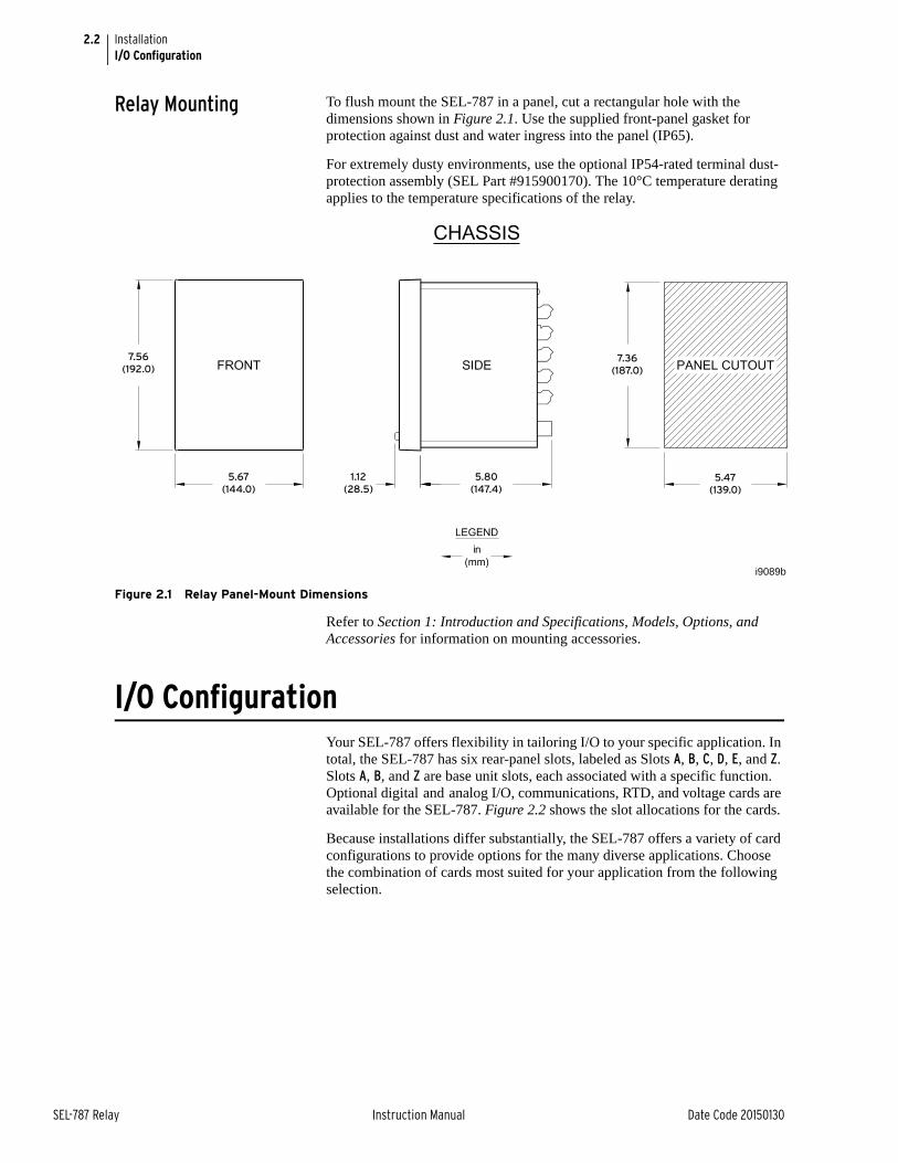
2.2
SEL-787 Relay Instruction Manual Date Code 20150130
InstallationI/O Configuration
Relay Mounting To flush mount the SEL-787 in a panel, cut a rectangular hole with the dimensions shown in Figure 2.1. Use the supplied front-panel gasket for protection against dust and water ingress into the panel (IP65).
For extremely dusty environments, use the optional IP54-rated terminal dust-protection assembly (SEL Part #915900170). The 10°C temperature derating applies to the temperature specifications of the relay.
Figure 2.1 Relay Panel-Mount Dimensions
Refer to Section 1: Introduction and Specifications, Models, Options, and Accessories for information on mounting accessories.
I/O ConfigurationYour SEL-787 offers flexibility in tailoring I/O to your specific application. In total, the SEL-787 has six rear-panel slots, labeled as Slots A, B, C, D, E, and Z. Slots A, B, and Z are base unit slots, each associated with a specific function. Optional digital and analog I/O, communications, RTD, and voltage cards are available for the SEL-787. Figure 2.2 shows the slot allocations for the cards.
Because installations differ substantially, the SEL-787 offers a variety of card configurations to provide options for the many diverse applications. Choose the combination of cards most suited for your application from the following selection.
5.47
(139.0)
7.36
(187.0)
5.80
(147.4)
5.67
(144.0)
7.56
(192.0)
1.12
(28.5)
i9089b
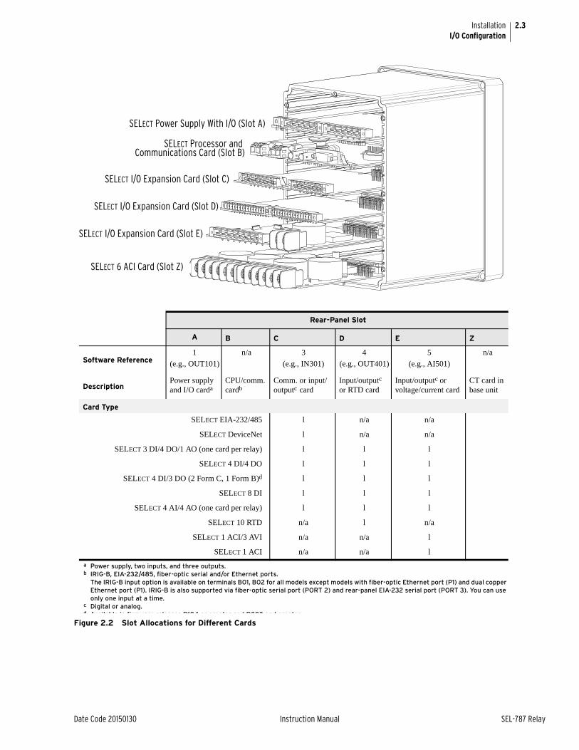
2.3
Date Code 20150130 Instruction Manual SEL-787 Relay
InstallationI/O Configuration
Figure 2.2 Slot Allocations for Different Cards
SELECT Power Supply With I/O (Slot A)
SELECT Processor and Communications Card (Slot B)
SELECT I/O Expansion Card (Slot C)
SELECT I/O Expansion Card (Slot D)
SELECT I/O Expansion Card (Slot E)
SELECT 6 ACI Card (Slot Z)
Rear-Panel Slot
A B C D E Z
Software Reference1
(e.g., OUT101)
n/a 3
(e.g., IN301)
4
(e.g., OUT401)
5
(e.g., AI501)
n/a
DescriptionPower supply and I/O carda
a Power supply, two inputs, and three outputs.
CPU/comm. cardb
b IRIG-B, EIA-232/485, fiber-optic serial and/or Ethernet ports.The IRIG-B input option is available on terminals B01, B02 for all models except models with fiber-optic Ethernet port (P1) and dual copper Ethernet port (P1). IRIG-B is also supported via fiber-optic serial port (PORT 2) and rear-panel EIA-232 serial port (PORT 3). You can use only one input at a time.
Comm. or input/outputc card
c Digital or analog.
Input/outputc or RTD card
Input/outputc or voltage/current card
CT card in base unit
Card Type
SELECT EIA-232/485 l n/a n/a
SELECT DeviceNet l n/a n/a
SELECT 3 DI/4 DO/1 AO (one card per relay) l l l
SELECT 4 DI/4 DO l l l
SELECT 4 DI/3 DO (2 Form C, 1 Form B)d l l l
SELECT 8 DI l l l
SELECT 4 AI/4 AO (one card per relay) l l l
SELECT 10 RTD n/a l n/a
SELECT 1 ACI/3 AVI n/a n/a l
SELECT 1 ACI n/a n/a l
d Available in firmware releases R104 or greater and R203 and greater
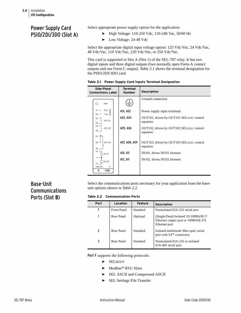
2.4
SEL-787 Relay Instruction Manual Date Code 20150130
InstallationI/O Configuration
Power Supply Card PSIO/2DI/3DO (Slot A)
Select appropriate power supply option for the application:
➤ High Voltage: 110-250 Vdc, 110-240 Vac, 50/60 Hz
➤ Low Voltage: 24-48 Vdc
Select the appropriate digital input voltage option: 125 Vdc/Vac, 24 Vdc/Vac, 48 Vdc/Vac, 110 Vdc/Vac, 220 Vdc/Vac, or 250 Vdc/Vac.
This card is supported in Slot A (Slot 1) of the SEL-787 relay. It has two digital inputs and three digital outputs (two normally open Form-A contact outputs and one Form-C output). Table 2.1 shows the terminal designation for the PSIO/2DI/3DO card.
Base-Unit Communications Ports (Slot B)
Select the communications ports necessary for your application from the base-unit options shown in Table 2.2.
Port F supports the following protocols:
➤ SELBOOT
➤ Modbus® RTU Slave
➤ SEL ASCII and Compressed ASCII
➤ SEL Settings File Transfer
Table 2.1 Power Supply Card Inputs Terminal Designation
Side-PanelConnections Label
Terminal Number Description
Ground connection
A01, A02 Power supply input terminals
A03, A04 OUT101, driven by OUT101 SELOGIC control equation
A05, A06 OUT102, driven by OUT102 SELOGIC control equation
A07, A08, A09 OUT103, driven by OUT103 SELOGIC control equation
A10, A11 IN101, drives IN101 element
A12, A11 IN102, drives IN102 element
A 100
OUT_0 1
OUT_02
IN_0 1
IN_02
10
1 1
08
12
INPUTS:
05
06
04
03
02
0 1
GND
+/H
—/N
PO
WE
R
OUT_03
09
07
Table 2.2 Communication Ports
Port Location Feature Description
F Front Panel Standard Nonisolated EIA-232 serial port
1 Rear Panel Optional (Single/Dual) Isolated 10/100BASE-T Ethernet copper port or 100BASE-FX Ethernet port
2 Rear Panel Standard Isolated multimode fiber-optic serial port with ST® connectors
3 Rear Panel Standard Nonisolated EIA-232 or isolated EIA-485 serial port
2.5
Date Code 20150130 Instruction Manual SEL-787 Relay
InstallationI/O Configuration
➤ Event Messenger
➤ C37.118 (Synchrophasor Data)
Port 1 (Ethernet) supports the following protocols:
➤ Modbus TCP/IP
➤ DNP3 LAN/WAN
➤ IEC 61850
➤ Simple Network Time Protocol (SNTP)
➤ FTP
➤ Telnet
Port 2 and Port 3 support the following protocols:
➤ Modbus RTU Slave
➤ SEL ASCII and Compressed ASCII
➤ SEL Fast Meter
➤ SEL Fast Operate
➤ SEL Fast SER
➤ SEL Fast Message Unsolicited Write
➤ SEL Settings File Transfer
➤ SEL MIRRORED BITS® (MBA, MBB, MB8A, MB8B, MBTA, MBTB)
➤ Event Messenger
➤ DNP3 Slave Level 2
➤ C37.118 (Synchrophasor Data)
Communications Card Either the DeviceNet (see Appendix G: DeviceNet Communications) or the EIA-232/ EIA-485 communications card is supported in Slot C. The EIA-232/EIA-485 card provides one serial port with one of the following two serial port interfaces:
➤ Port 4A, an isolated EIA-485 serial port interface
➤ Port 4C, nonisolated EIA-232 serial port interface, supporting the +5 Vdc interface
Select either EIA-232 or EIA-485 functionality using the Port 4 Setting COMM Interface. Table 2.3 shows the port number, interface, and type of connector for the two protocols.
The communications card supports all of the following protocols:
➤ Modbus RTU Slave
➤ SEL ASCII and Compressed ASCII
➤ SEL Fast Meter
➤ SEL Fast Operate
➤ SEL Fast SER
Table 2.3 Communication Card Interfaces and Connectors
Port Interface Connectors
4A EIA-485 5-pin Euro
4C EIA-232 D-sub
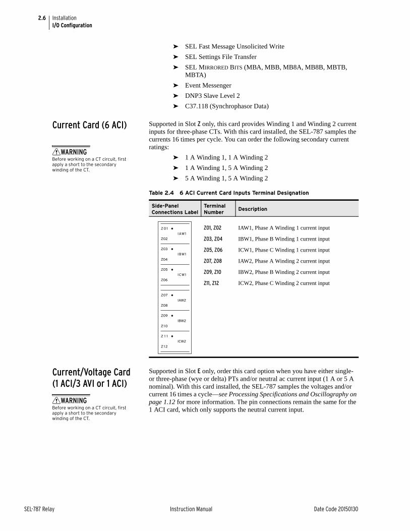
2.6
SEL-787 Relay Instruction Manual Date Code 20150130
InstallationI/O Configuration
➤ SEL Fast Message Unsolicited Write
➤ SEL Settings File Transfer
➤ SEL MIRRORED BITS (MBA, MBB, MB8A, MB8B, MBTB, MBTA)
➤ Event Messenger
➤ DNP3 Slave Level 2
➤ C37.118 (Synchrophasor Data)
Current Card (6 ACI) Supported in Slot Z only, this card provides Winding 1 and Winding 2 current inputs for three-phase CTs. With this card installed, the SEL-787 samples the currents 16 times per cycle. You can order the following secondary current ratings:
➤ 1 A Winding 1, 1 A Winding 2
➤ 1 A Winding 1, 5 A Winding 2
➤ 5 A Winding 1, 5 A Winding 2
Current/Voltage Card (1 ACI/3 AVI or 1 ACI)
Supported in Slot E only, order this card option when you have either single- or three-phase (wye or delta) PTs and/or neutral ac current input (1 A or 5 A nominal). With this card installed, the SEL-787 samples the voltages and/or current 16 times a cycle—see Processing Specifications and Oscillography on page 1.12 for more information. The pin connections remain the same for the 1 ACI card, which only supports the neutral current input.
Table 2.4 6 ACI Current Card Inputs Terminal Designation
Side-PanelConnections Label
Terminal Number
Description
Z01, Z02 IAW1, Phase A Winding 1 current input
Z03, Z04 IBW1, Phase B Winding 1 current input
Z05, Z06 ICW1, Phase C Winding 1 current input
Z07, Z08 IAW2, Phase A Winding 2 current input
Z09, Z10 IBW2, Phase B Winding 2 current input
Z11, Z12 ICW2, Phase C Winding 2 current input
WARNINGBefore working on a CT circuit, first apply a short to the secondary winding of the CT.
WARNINGBefore working on a CT circuit, first apply a short to the secondary winding of the CT.
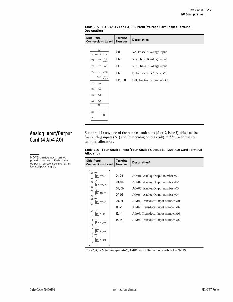
2.7
Date Code 20150130 Instruction Manual SEL-787 Relay
InstallationI/O Configuration
Analog Input/Output Card (4 AI/4 AO)
Supported in any one of the nonbase unit slots (Slot C, D, or E), this card has four analog inputs (AI) and four analog outputs (AO). Table 2.6 shows the terminal allocation.
Table 2.5 1 ACI/3 AVI or 1 ACI Current/Voltage Card Inputs Terminal Designation
Side-PanelConnections Label
Terminal Number
Description
E01 VA, Phase A voltage input
E02 VB, Phase B voltage input
E03 VC, Phase C voltage input
E04 N, Return for VA, VB, VC
E09, E10 IN1, Neutral current input 1
ACI
AVI
E 1 0
IN
E09
WYE OPENDELTA
E05
E06
N/C
N/CE08
E07
N/C
N/C
E02 VBVB
(COM)
E03 VC VC
E04 N COM
VA VAE 0 1
Table 2.6 Four Analog Input/Four Analog Output (4 AI/4 AO) Card Terminal Allocation
Side-Panel Connections Label
Terminal Number
Descriptiona
a x=3, 4, or 5 (for example, AI401, AI402, etc., if the card was installed in Slot D).
01, 02 AOx01, Analog Output number x01
03, 04 AOx02, Analog Output number x02
05, 06 AOx03, Analog Output number x03
07, 08 AOx04, Analog Output number x04
09, 10 AIx01, Transducer Input number x01
11, 12 AIx02, Transducer Input number x02
13, 14 AIx03, Transducer Input number x03
15, 16 AIx04, Transducer Input number x04
NOTE: Analog inputs cannot provide loop power. Each analog output is self-powered and has an isolated power supply.
AO_02
AO_0 1
AO_03
AO_04
AI_02
AI_0 1
AI_03
AI_04
08
05
06
02
04
09
03
10
1 1
12
1 3
14
15
16
07
0 1
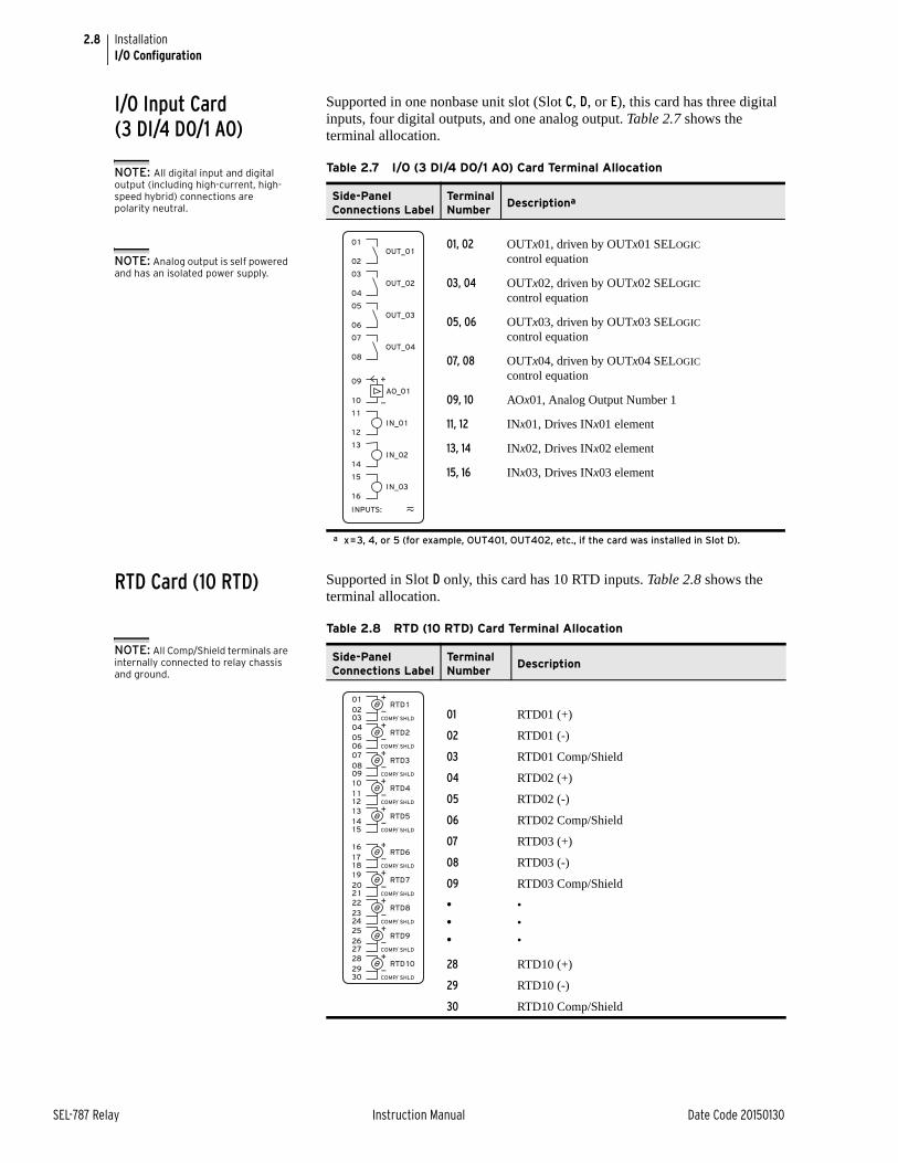
2.8
SEL-787 Relay Instruction Manual Date Code 20150130
InstallationI/O Configuration
I/O Input Card (3 DI/4 DO/1 AO)
Supported in one nonbase unit slot (Slot C, D, or E), this card has three digital inputs, four digital outputs, and one analog output. Table 2.7 shows the terminal allocation.
RTD Card (10 RTD) Supported in Slot D only, this card has 10 RTD inputs. Table 2.8 shows the terminal allocation.
Table 2.7 I/O (3 DI/4 DO/1 AO) Card Terminal Allocation
Side-PanelConnections Label
TerminalNumber
Descriptiona
a x=3, 4, or 5 (for example, OUT401, OUT402, etc., if the card was installed in Slot D).
01, 02 OUTx01, driven by OUTx01 SELOGIC control equation
03, 04 OUTx02, driven by OUTx02 SELOGIC control equation
05, 06 OUTx03, driven by OUTx03 SELOGIC control equation
07, 08 OUTx04, driven by OUTx04 SELOGIC control equation
09, 10 AOx01, Analog Output Number 1
11, 12 INx01, Drives INx01 element
13, 14 INx02, Drives INx02 element
15, 16 INx03, Drives INx03 element
NOTE: All digital input and digital output (including high-current, high-speed hybrid) connections are polarity neutral.
NOTE: Analog output is self powered and has an isolated power supply.
INPUTS:
AO_0 1
IN_0 1
IN_02
IN_03
OUT_0 1
OUT_02
OUT_03
OUT_04
08
05
06
02
04
09
03
10
1 1
12
1 3
14
15
16
07
0 1
+
—
Table 2.8 RTD (10 RTD) Card Terminal Allocation
Side-PanelConnections Label
Terminal Number
Description
01 RTD01 (+)
02 RTD01 (-)
03 RTD01 Comp/Shield
04 RTD02 (+)
05 RTD02 (-)
06 RTD02 Comp/Shield
07 RTD03 (+)
08 RTD03 (-)
09 RTD03 Comp/Shield
•
•
•
•
•
•
28 RTD10 (+)
29 RTD10 (-)
30 RTD10 Comp/Shield
NOTE: All Comp/Shield terminals are internally connected to relay chassis and ground.
08
0506
04
09
202 1
22
2324
25
2627
28
2930
10
1 112
1 3
1415
16
1718
19
07
0203
0 1RTD 1
COMP/ SHLD
+
—
RTD2
COMP/ SHLD
+
—
RTD3
COMP/ SHLD
+
—
RTD4
COMP/ SHLD
+
—
RTD5
COMP/ SHLD
+
—
RTD6
COMP/ SHLD
+
—
RTD7
COMP/ SHLD
+
—
RTD8
COMP/ SHLD
+
—
RTD9
COMP/ SHLD
+
—
RTD 10
COMP/ SHLD
+
—
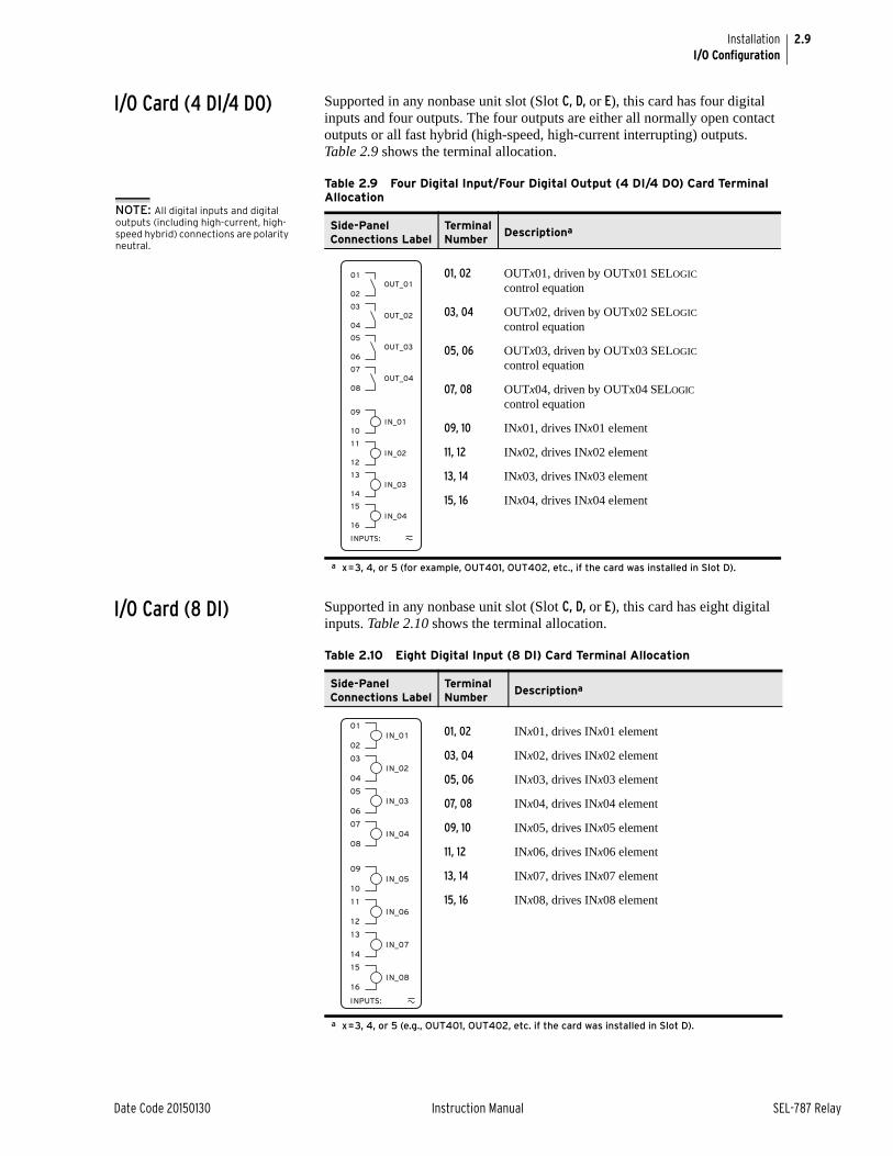
2.9
Date Code 20150130 Instruction Manual SEL-787 Relay
InstallationI/O Configuration
I/O Card (4 DI/4 DO) Supported in any nonbase unit slot (Slot C, D, or E), this card has four digital inputs and four outputs. The four outputs are either all normally open contact outputs or all fast hybrid (high-speed, high-current interrupting) outputs. Table 2.9 shows the terminal allocation.
I/O Card (8 DI) Supported in any nonbase unit slot (Slot C, D, or E), this card has eight digital inputs. Table 2.10 shows the terminal allocation.
Table 2.9 Four Digital Input/Four Digital Output (4 DI/4 DO) Card Terminal Allocation
Side-PanelConnections Label
TerminalNumber
Descriptiona
a x=3, 4, or 5 (for example, OUT401, OUT402, etc., if the card was installed in Slot D).
01, 02 OUTx01, driven by OUTx01 SELOGIC control equation
03, 04 OUTx02, driven by OUTx02 SELOGIC control equation
05, 06 OUTx03, driven by OUTx03 SELOGIC control equation
07, 08 OUTx04, driven by OUTx04 SELOGIC control equation
09, 10 INx01, drives INx01 element
11, 12 INx02, drives INx02 element
13, 14 INx03, drives INx03 element
15, 16 INx04, drives INx04 element
NOTE: All digital inputs and digital outputs (including high-current, high-speed hybrid) connections are polarity neutral.
INPUTS:
IN_0 1
IN_02
IN_03
IN_04
OUT_0 1
OUT_02
OUT_03
OUT_04
08
05
06
02
04
09
03
10
1 1
12
1 3
14
15
16
07
0 1
Table 2.10 Eight Digital Input (8 DI) Card Terminal Allocation
Side-PanelConnections Label
Terminal Number
Descriptiona
a x=3, 4, or 5 (e.g., OUT401, OUT402, etc. if the card was installed in Slot D).
01, 02 INx01, drives INx01 element
03, 04 INx02, drives INx02 element
05, 06 INx03, drives INx03 element
07, 08 INx04, drives INx04 element
09, 10 INx05, drives INx05 element
11, 12 INx06, drives INx06 element
13, 14 INx07, drives INx07 element
15, 16 INx08, drives INx08 element
INPUTS:
08
05
06
02
04
09
03
10
1 1
12
1 3
14
15
16
07
0 1
IN_0 1
IN_02
IN_03
IN_04
IN_05
IN_06
IN_07
IN_08
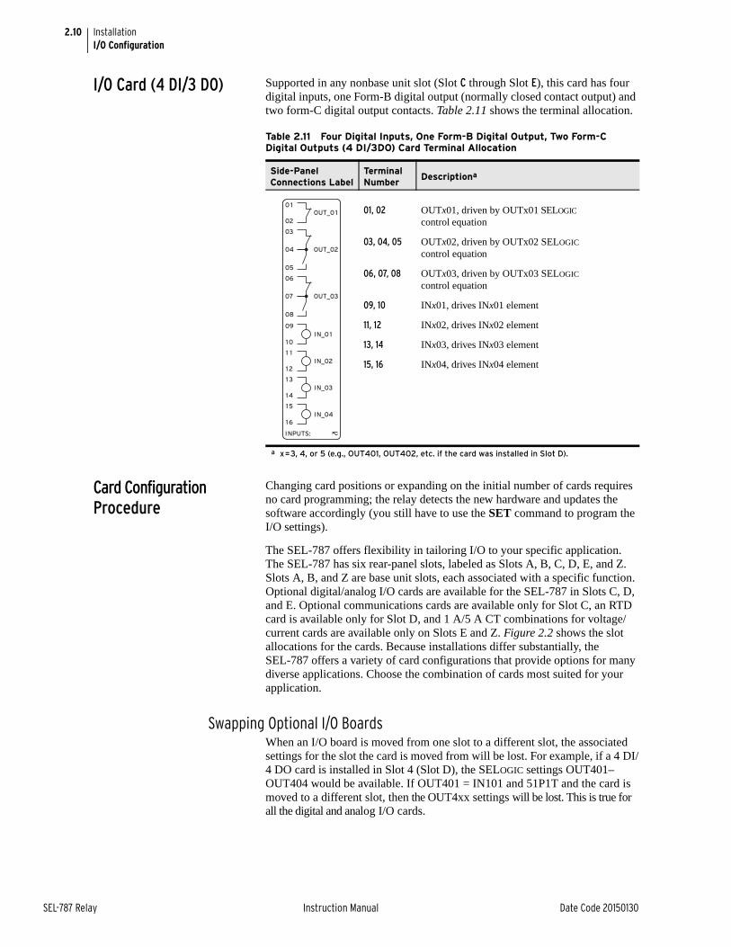
2.10
SEL-787 Relay Instruction Manual Date Code 20150130
InstallationI/O Configuration
I/O Card (4 DI/3 DO) Supported in any nonbase unit slot (Slot C through Slot E), this card has four digital inputs, one Form-B digital output (normally closed contact output) and two form-C digital output contacts. Table 2.11 shows the terminal allocation.
Card Configuration Procedure
Changing card positions or expanding on the initial number of cards requires no card programming; the relay detects the new hardware and updates the software accordingly (you still have to use the SET command to program the I/O settings).
The SEL-787 offers flexibility in tailoring I/O to your specific application. The SEL-787 has six rear-panel slots, labeled as Slots A, B, C, D, E, and Z. Slots A, B, and Z are base unit slots, each associated with a specific function. Optional digital/analog I/O cards are available for the SEL-787 in Slots C, D, and E. Optional communications cards are available only for Slot C, an RTD card is available only for Slot D, and 1 A/5 A CT combinations for voltage/current cards are available only on Slots E and Z. Figure 2.2 shows the slot allocations for the cards. Because installations differ substantially, the SEL-787 offers a variety of card configurations that provide options for many diverse applications. Choose the combination of cards most suited for your application.
Swapping Optional I/O BoardsWhen an I/O board is moved from one slot to a different slot, the associated settings for the slot the card is moved from will be lost. For example, if a 4 DI/4 DO card is installed in Slot 4 (Slot D), the SELOGIC settings OUT401–OUT404 would be available. If OUT401 = IN101 and 51P1T and the card is moved to a different slot, then the OUT4xx settings will be lost. This is true for all the digital and analog I/O cards.
Table 2.11 Four Digital Inputs, One Form-B Digital Output, Two Form-C Digital Outputs (4 DI/3DO) Card Terminal Allocation
Side-PanelConnections Label
TerminalNumber
Descriptiona
a x=3, 4, or 5 (e.g., OUT401, OUT402, etc. if the card was installed in Slot D).
01, 02 OUTx01, driven by OUTx01 SELOGIC control equation
03, 04, 05 OUTx02, driven by OUTx02 SELOGIC control equation
06, 07, 08 OUTx03, driven by OUTx03 SELOGIC control equation
09, 10 INx01, drives INx01 element
11, 12 INx02, drives INx02 element
13, 14 INx03, drives INx03 element
15, 16 INx04, drives INx04 element
INPUTS:
IN_0 1
IN_02
IN_03
IN_04
OUT_0 1
OUT_02
02
04
05
09
03
OUT_0307
08
06
10
1 1
12
1 3
14
15
16
0 1
2.11
Date Code 20150130 Instruction Manual SEL-787 Relay
InstallationI/O Configuration
Card Installation for Slots C, D, E, and ZPerform the following steps to install cards in Slots C, D, E, or Z of the base unit.
Step 1. Remove the power supply voltage from terminals A01+ and A02– and remove the ground wire from the green ground screw.
Step 2. Disconnect all the connection plugs.
Step 3. Loosen the eight (8) screws on the rear and remove the rear cover.
Step 4. Remove the plastic filler plate covering the slot associated with the card being installed.
Step 5. Insert the card in the correct slot.
Make sure the contact fingers on the printed circuit board are bent at an approximately 130° angle relative to the board for proper electromagnetic interference protection.
Step 6. Before reattaching the rear cover, check for and remove any foreign material that may remain inside the SEL-787 case.
Step 7. Carefully reattach the rear cover.
Step 8. Tighten the eight (8) screws that secure the rear cover to the case.
Step 9. Apply power supply voltage to terminals A01+ and A02– and reconnect the ground wire to the green ground screw.
Step 10. If the card is in the proper slot, the front panel displays the following:
STATUS FAILX Card Failure
If you do not see this message and the ENABLED light is turned on, the card was inserted into the wrong slot. Begin again at Step 1.
If you do see this message, proceed to Step 11.
Step 11. Press the ESC pushbutton.
Step 12. Press the Down Arrow pushbutton until STATUS is highlighted.
Step 13. Press the ENT pushbutton.
The front panel displays the following:STATUSRelay Status
Step 14. Press the ENT button.
The front panel displays the following:Serial Num000000000000000000000000
Step 15. Press the ENT pushbutton.
The front panel displays the following:Confirm HardwareConfig (Enter)
DANGERDisconnect or de-energize all external connections before opening this device. Contact with hazardous voltages and currents inside this device can cause electrical shock resulting in injury or death.
2.12
SEL-787 Relay Instruction Manual Date Code 20150130
InstallationI/O Configuration
Step 16. Press the ENT pushbutton.
The front panel displays the following:Accept New Config?No Yes
Step 17. Select Yes and press the ENT pushbutton.
The front panel displays the following:Config AcceptedEnter to Reboot
Step 18. Press the ENT pushbutton.
The relay restarts and the ENABLED light turns on to indicate the card was installed correctly.
After reconfiguration, the relay updates the part number, except for the following indicated digits. These digits remain unchanged, i.e., these digits retain the same character as before the reconfiguration. Also, a communications card installed in Slot C is reflected as an empty slot in the part number. A regular 4 DI/4 DO card and a hybrid 4 DI/4 DO card have the same device ID. When interchanging these two cards, the part number for the respective slots should be updated manually.
Use the Status command to view the part number.
Use the PARTNO command from the 2AC level to enter the exact part number of the relay.
Step 19. Update the side-panel drawing with the drawing sticker provided in the card kit. If necessary, replace the rear panel with the one applicable for the card and attach the terminal-marking label provided with the card to the rear-panel cover.
Step 20. Reconnect all of the connection plugs and add any additional wiring/connectors required by the new card.
Slot B CPU Card ReplacementWhen replacing the Slot B card, be aware of the following issues.
1. The new card will ship with the latest firmware from the factory.
2. The firmware revision history should be reviewed for the changes that were made; note that new settings added, if any, might affect existing settings in the relay or its application.
3. If the IEC 61850 protocol option was used previously, verify that the IEC 61850 protocol is still operational after the replacement. If not, reenable it. Refer to Relays With IEC 61850 Option in Appendix B: Firmware Upgrade Instructions, for the verification process.
4. Save all the settings and event reports before replacing the card.
PART NUM = 0 7 8 7 0 X 1 A 6 X 3 A 1 A 8 5 0 2 0 X
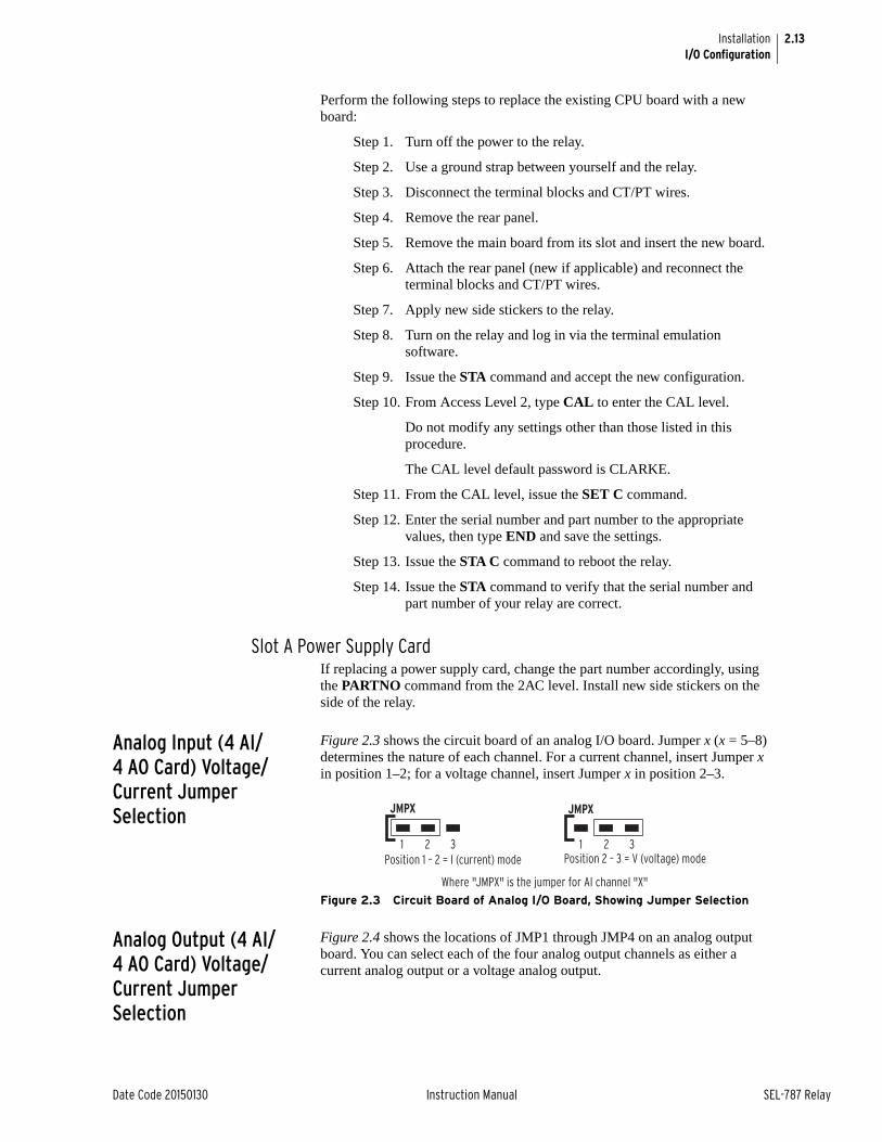
2.13
Date Code 20150130 Instruction Manual SEL-787 Relay
InstallationI/O Configuration
Perform the following steps to replace the existing CPU board with a new board:
Step 1. Turn off the power to the relay.
Step 2. Use a ground strap between yourself and the relay.
Step 3. Disconnect the terminal blocks and CT/PT wires.
Step 4. Remove the rear panel.
Step 5. Remove the main board from its slot and insert the new board.
Step 6. Attach the rear panel (new if applicable) and reconnect the terminal blocks and CT/PT wires.
Step 7. Apply new side stickers to the relay.
Step 8. Turn on the relay and log in via the terminal emulation software.
Step 9. Issue the STA command and accept the new configuration.
Step 10. From Access Level 2, type CAL to enter the CAL level.
Do not modify any settings other than those listed in this procedure.
The CAL level default password is CLARKE.
Step 11. From the CAL level, issue the SET C command.
Step 12. Enter the serial number and part number to the appropriate values, then type END and save the settings.
Step 13. Issue the STA C command to reboot the relay.
Step 14. Issue the STA command to verify that the serial number and part number of your relay are correct.
Slot A Power Supply CardIf replacing a power supply card, change the part number accordingly, using the PARTNO command from the 2AC level. Install new side stickers on the side of the relay.
Analog Input (4 AI/4 AO Card) Voltage/Current Jumper Selection
Figure 2.3 shows the circuit board of an analog I/O board. Jumper x (x = 5–8) determines the nature of each channel. For a current channel, insert Jumper x in position 1–2; for a voltage channel, insert Jumper x in position 2–3.
Figure 2.3 Circuit Board of Analog I/O Board, Showing Jumper Selection
Analog Output (4 AI/4 AO Card) Voltage/Current Jumper Selection
Figure 2.4 shows the locations of JMP1 through JMP4 on an analog output board. You can select each of the four analog output channels as either a current analog output or a voltage analog output.
JMPX
21 3 21 3
JMPX
Position 2 – 3 = V (voltage) mode
Where "JMPX" is the jumper for AI channel "X"
Position 1 – 2 = I (current) mode
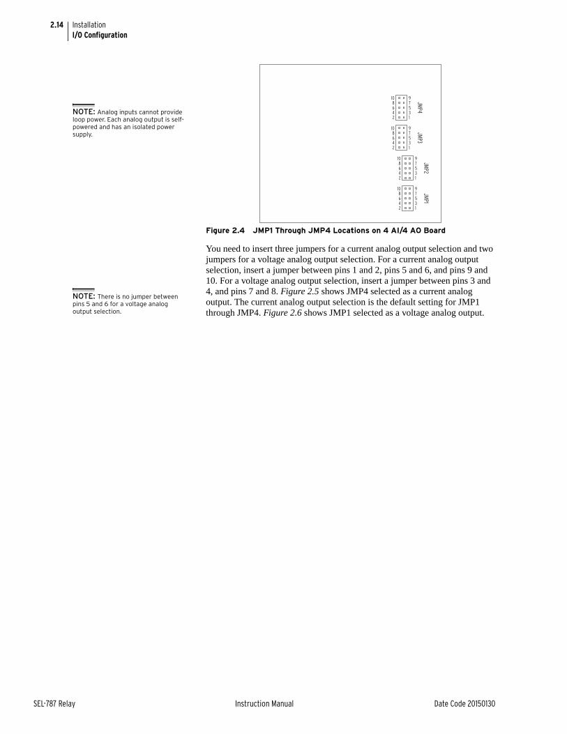
2.14
SEL-787 Relay Instruction Manual Date Code 20150130
InstallationI/O Configuration
Figure 2.4 JMP1 Through JMP4 Locations on 4 AI/4 AO Board
You need to insert three jumpers for a current analog output selection and two jumpers for a voltage analog output selection. For a current analog output selection, insert a jumper between pins 1 and 2, pins 5 and 6, and pins 9 and 10. For a voltage analog output selection, insert a jumper between pins 3 and 4, and pins 7 and 8. Figure 2.5 shows JMP4 selected as a current analog output. The current analog output selection is the default setting for JMP1 through JMP4. Figure 2.6 shows JMP1 selected as a voltage analog output.
97531
108642
JMP1
97531
108642
JMP2
97531
108642
JMP3
97531
108642
JMP4NOTE: Analog inputs cannot provide
loop power. Each analog output is self-powered and has an isolated power supply.
NOTE: There is no jumper between pins 5 and 6 for a voltage analog output selection.
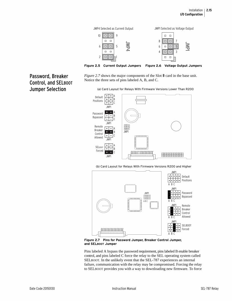
2.15
Date Code 20150130 Instruction Manual SEL-787 Relay
InstallationI/O Configuration
Password, Breaker Control, and SELBOOT Jumper Selection
Figure 2.7 shows the major components of the Slot B card in the base unit. Notice the three sets of pins labeled A, B, and C.
Figure 2.7 Pins for Password Jumper, Breaker Control Jumper, and SELBOOT Jumper
Pins labeled A bypass the password requirement, pins labeled B enable breaker control, and pins labeled C force the relay to the SEL operating system called SELBOOT. In the unlikely event that the SEL-787 experiences an internal failure, communication with the relay may be compromised. Forcing the relay to SELBOOT provides you with a way to downloading new firmware. To force
Figure 2.5 Current Output Jumpers Figure 2.6 Voltage Output Jumpers
9
5
1
10
6
2
JMP4
JMP4 Selected as Current Output
7
5
3
8
6
4
JMP1
JMP1 Selected as Voltage Output
JMP1
A B C
JMP1
A B C
JMP1
A B C
JMP1
A B C
PasswordBypassed
DefaultPositions
SELBOOTForced
Remote Breaker Control Allowed
JMP1
(b) Card Layout for Relays With Firmware Versions R200 and Higher
(a) Card Layout for Relays With Firmware Versions Lower Than R200
ABC
JMP1
ABC
JMP1
ABC
JMP1
Default Positions
Password Bypassed
Remote Breaker Control Allowed
ABC
JMP1
SELBOOT
Forced
ABC
JMP1
A B C
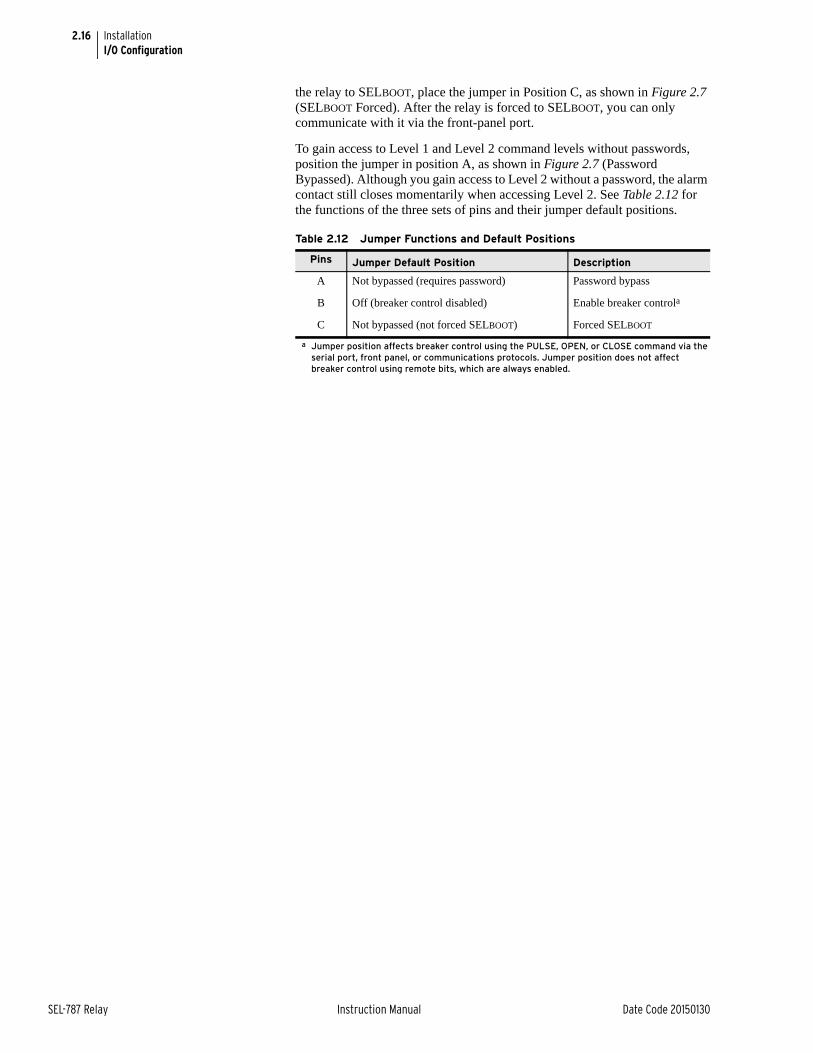
2.16
SEL-787 Relay Instruction Manual Date Code 20150130
InstallationI/O Configuration
the relay to SELBOOT, place the jumper in Position C, as shown in Figure 2.7 (SELBOOT Forced). After the relay is forced to SELBOOT, you can only communicate with it via the front-panel port.
To gain access to Level 1 and Level 2 command levels without passwords, position the jumper in position A, as shown in Figure 2.7 (Password Bypassed). Although you gain access to Level 2 without a password, the alarm contact still closes momentarily when accessing Level 2. See Table 2.12 for the functions of the three sets of pins and their jumper default positions.
Table 2.12 Jumper Functions and Default Positions
Pins Jumper Default Position Description
A Not bypassed (requires password) Password bypass
B Off (breaker control disabled) Enable breaker controla
a Jumper position affects breaker control using the PULSE, OPEN, or CLOSE command via the serial port, front panel, or communications protocols. Jumper position does not affect breaker control using remote bits, which are always enabled.
C Not bypassed (not forced SELBOOT) Forced SELBOOT
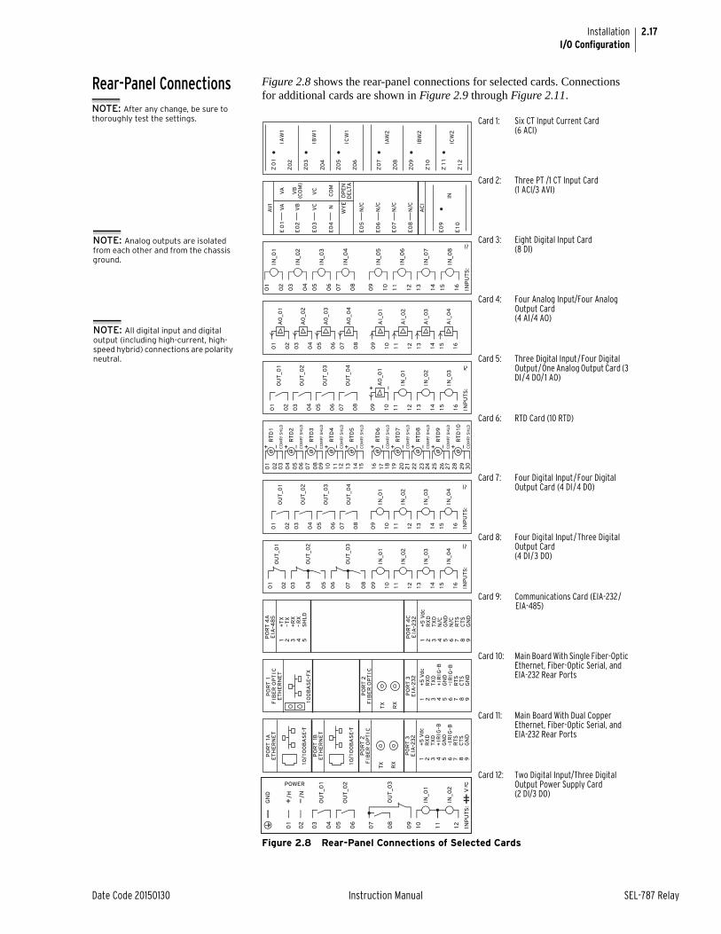
2.17
Date Code 20150130 Instruction Manual SEL-787 Relay
InstallationI/O Configuration
Rear-Panel Connections Figure 2.8 shows the rear-panel connections for selected cards. Connections for additional cards are shown in Figure 2.9 through Figure 2.11.
Figure 2.8 Rear-Panel Connections of Selected Cards
Card 1: Six CT Input Current Card(6 ACI)
Card 2: Three PT /1 CT Input Card(1 ACI/3 AVI)
Card 3: Eight Digital Input Card (8 DI)
Card 4: Four Analog Input/Four Analog Output Card (4 AI/4 AO)
Card 5: Three Digital Input/Four Digital Output/One Analog Output Card (3 DI/4 DO/1 AO)
Card 6: RTD Card (10 RTD)
Card 7: Four Digital Input/Four Digital Output Card (4 DI/4 DO)
Card 8: Four Digital Input/Three Digital Output Card (4 DI/3 DO)
Card 9: Communications Card (EIA-232/EIA-485)
Card 10: Main Board With Single Fiber-Optic Ethernet, Fiber-Optic Serial, and EIA-232 Rear Ports
Card 11: Main Board With Dual Copper Ethernet, Fiber-Optic Serial, and EIA-232 Rear Ports
Card 12: Two Digital Input/Three Digital Output Power Supply Card (2 DI/3 DO)
NOTE: After any change, be sure to thoroughly test the settings.
AC
I
AV
I
E10
IN
E0
9
WY
EO
PE
ND
ELT
A
E0
5
E0
6
N/C
N/C
E0
8
E0
7
N/C
N/C
E0
2V
BV
B(C
OM
)
E0
3V
CV
C
E0
4N
CO
M
VA
VA
E0
1
INP
UT
S:
08
05
06
02
04
09
03
10 11
12 13
14 15 1607
01
IN_0
1
IN_0
2
IN_0
3
IN_0
4
IN_0
5
IN_0
6
IN_0
7
IN_0
8
AO
_0
2
AO
_0
1
AO
_0
3
AO
_0
4
AI_
02
AI_
01
AI_
03
AI_
04
08
05
06
02
04
09
03
10 11
12 13
14 15 1607
01
INP
UT
S:
AO
_0
1
IN_0
1
IN_0
2
IN_0
3
OU
T_0
1
OU
T_0
2
OU
T_0
3
OU
T_0
4
08
05
06
02
04
09
03
10 11
12 13
14 15 1607
01
+ —
08
05
06
04
09
20
21
22
23
24
25
26
27
28
29
30
10 11
12 13
14 15 16 17 18 1907
02
03
01
RT
D1
CO
MP
/ S
HL
D
+ —
RT
D2
CO
MP
/ S
HL
D
+ —
RT
D3
CO
MP
/ S
HL
D
+ —
RT
D4
CO
MP
/ S
HL
D
+ —
RT
D5
CO
MP
/ S
HL
D
+ —
RT
D6
CO
MP
/ S
HL
D
+ —
RT
D7
CO
MP
/ S
HL
D
+ —
RT
D8
CO
MP
/ S
HL
D
+ —
RT
D9
CO
MP
/ S
HL
D
+ —
RT
D10
CO
MP
/ S
HL
D
+ —IN
PU
TS
:
IN_0
1
IN_0
2
IN_0
3
IN_0
4
OU
T_0
1
OU
T_0
2
OU
T_0
3
OU
T_0
4
08
05
06
02
04
09
03
10 11
12 13
14 15 1607
01
INP
UT
S:
IN_0
1
IN_0
2
IN_0
3
IN_0
4
OU
T_0
1
OU
T_0
2
02
04
05
09
03
OU
T_0
30
7
08
06
10 11
12 13
14 15 1601
PO
RT
4C
+5
Vd
cR
XD
N/C
TX
D
GN
D5
N/C
RT
S
GN
D
EIA
–23
2
1 2 43 6 8C
TS
7 9
+T
X–
TX
+R
X–
RX
SH
LD
5
PO
RT
4A
EIA
–48
5
1 2 43
+5
Vd
cR
XD
+IR
IG–B
TX
D
GN
D5
–IR
IG–B
RT
S
GN
D
PO
RT
3E
IA–2
32
PO
RT
2F
IBE
R O
PT
IC
TX
RX
1 2 43 6 8C
TS
7 9
PO
RT
1
ET
HE
RN
ET
100
BA
SE
–FX
FIB
ER
OP
TIC
+5
Vd
cR
XD
+IR
IG–B
TX
D
GN
D5
–IR
IG–B
RT
S
GN
D
PO
RT
3E
IA–2
32
PO
RT
2F
IBE
R O
PT
IC
TX
RX
1 2 43 6 8C
TS
7 9
PO
RT
1BE
TH
ER
NE
T
10/
100
BA
SE
–T
PO
RT
1AE
TH
ER
NE
T
10/
100
BA
SE
–T
NOTE: Analog outputs are isolated from each other and from the chassis ground.
NOTE: All digital input and digital output (including high-current, high-speed hybrid) connections are polarity neutral.

2.18
SEL-787 Relay Instruction Manual Date Code 20150130
InstallationRear-Panel Connections
Rear-Panel ConnectionsRear-Panel and Side-Panel Diagrams
The physical layout of the connectors on the rear-panel and side-panel diagrams of three sample configurations of the SEL-787 are shown in Figure 2.9, Figure 2.10, and Figure 2.11.
Figure 2.9 Dual-Fiber, Ethernet, EIA-232 Communication, 3 DI/4 DO/1 AO, and Current/Voltage (1 ACI/3 AVI) Option
Figure 2.10 Single Copper Ethernet, 8 DI, RTD, and 4 AI/4 AO Option
i4201a
PORT 2TX RX
1
9
PORT 3PORT 1A PORT 1B
(A) Rear-Panel Layout (B) Side-Panel Input and Output Designations
Z0
2
IAW
1
Z0
3
Z0
4
IBW
1
Z0
5
Z0
6
ICW
1
Z0
1
Z0
8
IAW
2
Z0
9
Z10
IBW
2
Z1
1
Z12
ICW
2
Z0
7
i4203a
(A) Rear-Panel Layout (B) Side-Panel Input and Output Designations
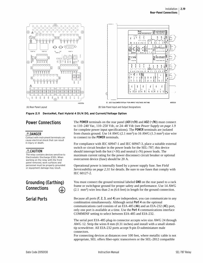
2.19
Date Code 20150130 Instruction Manual SEL-787 Relay
InstallationRear-Panel Connections
Figure 2.11 DeviceNet, Fast Hybrid 4 DI/4 DO, and Current/Voltage Option
Power Connections The POWER terminals on the rear panel (A01 (+/H) and A02 (—/N)) must connect to 110–240 Vac, 110–250 Vdc, or 24–48 Vdc (see Power Supply on page 1.9 for complete power input specifications). The POWER terminals are isolated from chassis ground. Use 14 AWG (2.1 mm2) to 16 AWG (1.3 mm2) size wire to connect to the POWER terminals.
For compliance with IEC 60947-1 and IEC 60947-3, place a suitable external switch or circuit breaker in the power leads for the SEL-787; this device should interrupt both the hot (+/H) and neutral (-/N) power leads. The maximum current rating for the power disconnect circuit breaker or optional overcurrent device (fuse) should be 20 A.
Operational power is internally fused by a power supply fuse. See Field Serviceability on page 2.31 for details. Be sure to use fuses that comply with IEC 60127-2.
Grounding (Earthing) Connections
You must connect the ground terminal labeled GND on the rear panel to a rack frame or switchgear ground for proper safety and performance. Use 14 AWG (2.1 mm2) wire less than 2 m (6.6 feet) in length for the ground connection.
Serial Ports Because all ports (F, 2, 3, and 4) are independent, you can communicate to any combination simultaneously. Although serial Port 4 on the optional communications card consists of an EIA-485 (4A) and an EIA-232 (4C) port, only one port is available at a time. Use the Port 4 communications interface COMMINF setting to select between EIA-485 and EIA-232.
The serial port EIA-485 plug-in connector accepts wire size AWG 24 through AWG 12. Strip the wires 8 mm (0.31 inches) and install with a small slotted-tip screwdriver. All EIA-232 ports accept 9-pin D-subminiature male connectors.For connecting devices at distances over 100 feet, where metallic cable is not appropriate, SEL offers fiber-optic transceivers or the SEL-2812 compatible
PORT 2TX RX
1
9
PORT 3PORT 1A PORT 1B
(A) Rear-Panel Layout (B) Side-Panel Input and Output Designations
DANGERContact with instrument terminals can cause electrical shock that can result in injury or death.
CAUTIONThe relay contains devices sensitive to Electrostatic Discharge (ESD). When working on the relay with the front panel removed, work surfaces and personnel must be properly grounded or equipment damage may result.
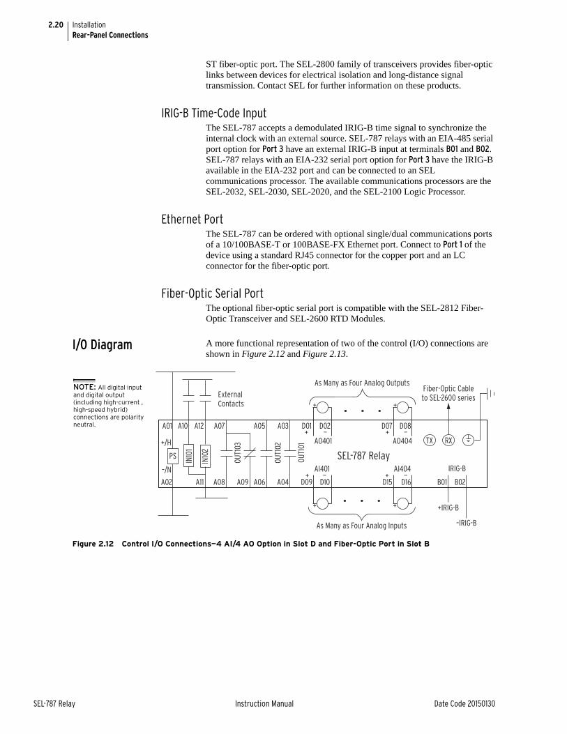
2.20
SEL-787 Relay Instruction Manual Date Code 20150130
InstallationRear-Panel Connections
ST fiber-optic port. The SEL-2800 family of transceivers provides fiber-optic links between devices for electrical isolation and long-distance signal transmission. Contact SEL for further information on these products.
IRIG-B Time-Code InputThe SEL-787 accepts a demodulated IRIG-B time signal to synchronize the internal clock with an external source. SEL-787 relays with an EIA-485 serial port option for Port 3 have an external IRIG-B input at terminals B01 and B02. SEL-787 relays with an EIA-232 serial port option for Port 3 have the IRIG-B available in the EIA-232 port and can be connected to an SEL communications processor. The available communications processors are the SEL-2032, SEL-2030, SEL-2020, and the SEL-2100 Logic Processor.
Ethernet PortThe SEL-787 can be ordered with optional single/dual communications ports of a 10/100BASE-T or 100BASE-FX Ethernet port. Connect to Port 1 of the device using a standard RJ45 connector for the copper port and an LC connector for the fiber-optic port.
Fiber-Optic Serial PortThe optional fiber-optic serial port is compatible with the SEL-2812 Fiber-Optic Transceiver and SEL-2600 RTD Modules.
I/O Diagram A more functional representation of two of the control (I/O) connections are shown in Figure 2.12 and Figure 2.13.
Figure 2.12 Control I/O Connections—4 AI/4 AO Option in Slot D and Fiber-Optic Port in Slot B
Fiber-Optic Cableto SEL-2600 series
+IRIG-B
–IRIG-B
IRIG-B
PS
A01
A02
–/N
+/H
External Contacts
SEL-787 Relay
RX
D07+
As Many as Four Analog Outputs
D08—
B01 B02
IN10
1
IN10
2
A10
A11
A12 A07
A08
OUT1
03
+ D15
— D16
D02—
— D10
D01+
+ D09
A03
A04
OUT1
01
A05
A06
OUT1
02
A09
TX
As Many as Four Analog Inputs
AO401 AO404
AI401 AI404
+ +
+ +
NOTE: All digital input and digital output (including high-current , high-speed hybrid) connections are polarity neutral.
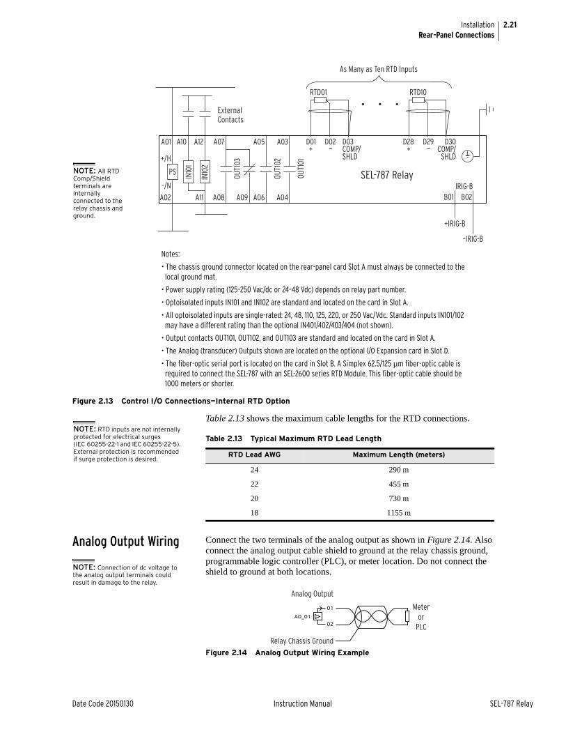
2.21
Date Code 20150130 Instruction Manual SEL-787 Relay
InstallationRear-Panel Connections
Figure 2.13 Control I/O Connections—Internal RTD Option
Table 2.13 shows the maximum cable lengths for the RTD connections.
Analog Output Wiring Connect the two terminals of the analog output as shown in Figure 2.14. Also connect the analog output cable shield to ground at the relay chassis ground, programmable logic controller (PLC), or meter location. Do not connect the shield to ground at both locations.
Figure 2.14 Analog Output Wiring Example
PS
A01
A02
–/N
+/H
ExternalContacts
SEL-787 RelayIN10
1
IN10
2
A10
A11
A12
+IRIG-B
–IRIG-B
IRIG-BB01 B02
A07
A08
OUT1
03
A03
A04
OUT1
01
A05
A06
OUT1
02
A09
D03COMP/SHLD
D02—
D01+
RTD01
D30COMP/SHLD
D29—
D28+
RTD10
As Many as Ten RTD Inputs
Notes:
• The chassis ground connector located on the rear-panel card Slot A must always be connected to the local ground mat.
• Power supply rating (125–250 Vac/dc or 24–48 Vdc) depends on relay part number.
• Optoisolated inputs IN101 and IN102 are standard and located on the card in Slot A.
• All optoisolated inputs are single-rated: 24, 48, 110, 125, 220, or 250 Vac/Vdc. Standard inputs IN101/102 may have a different rating than the optional IN401/402/403/404 (not shown).
• Output contacts OUT101, OUT102, and OUT103 are standard and located on the card in Slot A.
• The Analog (transducer) Outputs shown are located on the optional I/O Expansion card in Slot D.
• The fiber-optic serial port is located on the card in Slot B. A Simplex 62.5/125 µm fiber-optic cable is required to connect the SEL-787 with an SEL-2600 series RTD Module. This fiber-optic cable should be 1000 meters or shorter.
NOTE: All RTD Comp/Shield terminals are internally connected to the relay chassis and ground.
Table 2.13 Typical Maximum RTD Lead Length
RTD Lead AWG Maximum Length (meters)
24 290 m
22 455 m
20 730 m
18 1155 m
NOTE: RTD inputs are not internally protected for electrical surges (IEC 60255-22-1 and IEC 60255-22-5). External protection is recommended if surge protection is desired.
NOTE: Connection of dc voltage to the analog output terminals could result in damage to the relay.
Analog Output
Relay Chassis Ground
Meteror
PLCAO_0 1
02
0 1
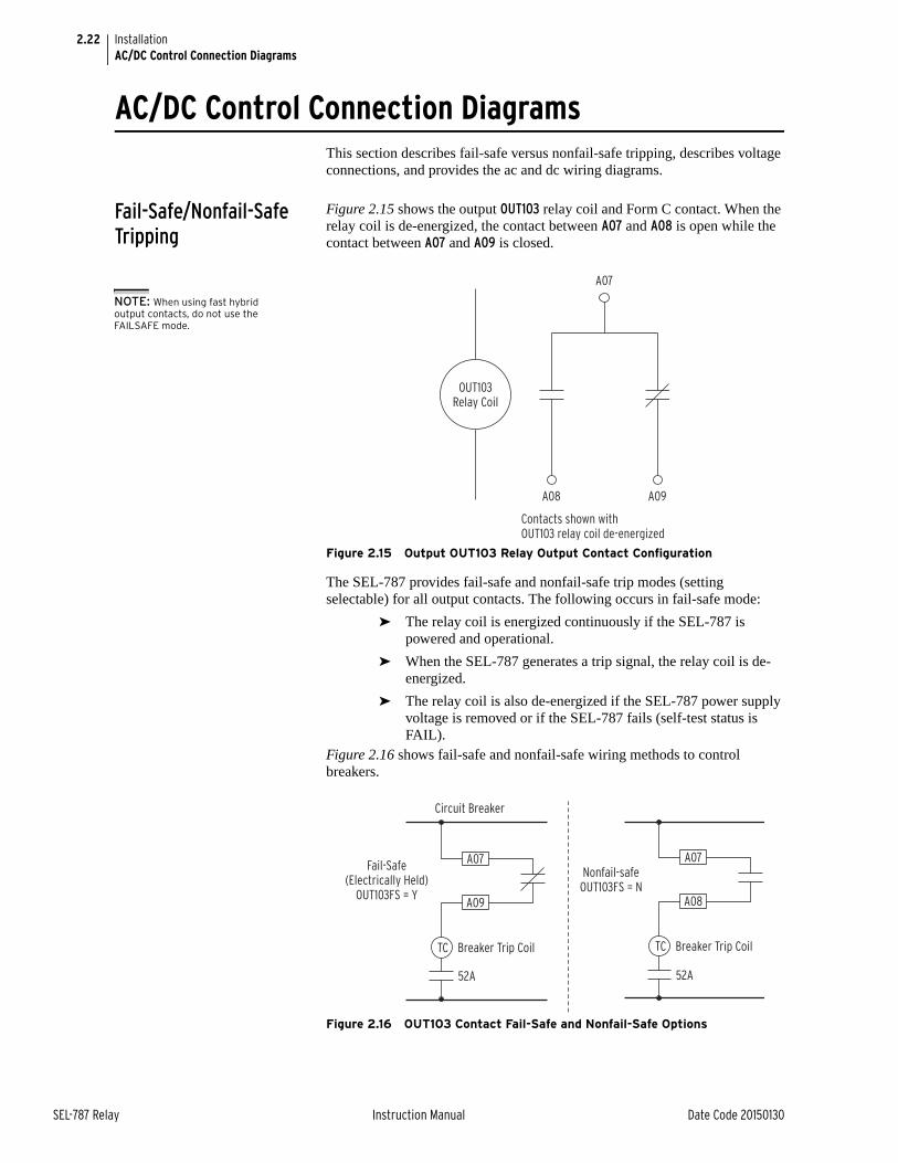
2.22
SEL-787 Relay Instruction Manual Date Code 20150130
InstallationAC/DC Control Connection Diagrams
AC/DC Control Connection DiagramsThis section describes fail-safe versus nonfail-safe tripping, describes voltage connections, and provides the ac and dc wiring diagrams.
Fail-Safe/Nonfail-Safe Tripping
Figure 2.15 shows the output OUT103 relay coil and Form C contact. When the relay coil is de-energized, the contact between A07 and A08 is open while the contact between A07 and A09 is closed.
Figure 2.15 Output OUT103 Relay Output Contact Configuration
The SEL-787 provides fail-safe and nonfail-safe trip modes (setting selectable) for all output contacts. The following occurs in fail-safe mode:
➤ The relay coil is energized continuously if the SEL-787 is powered and operational.
➤ When the SEL-787 generates a trip signal, the relay coil is de-energized.
➤ The relay coil is also de-energized if the SEL-787 power supply voltage is removed or if the SEL-787 fails (self-test status is FAIL).
Figure 2.16 shows fail-safe and nonfail-safe wiring methods to control breakers.
Figure 2.16 OUT103 Contact Fail-Safe and Nonfail-Safe Options
NOTE: When using fast hybrid output contacts, do not use the FAILSAFE mode.
A07
A08 A09
Contacts shown with OUT103 relay coil de-energized
OUT103Relay Coil
Nonfail-safeOUT103FS = N
52A
Breaker Trip CoilTC
A08
A07A07
TC
52A
Fail-Safe(Electrically Held)
OUT103FS = Y
Circuit Breaker
Breaker Trip Coil
A09
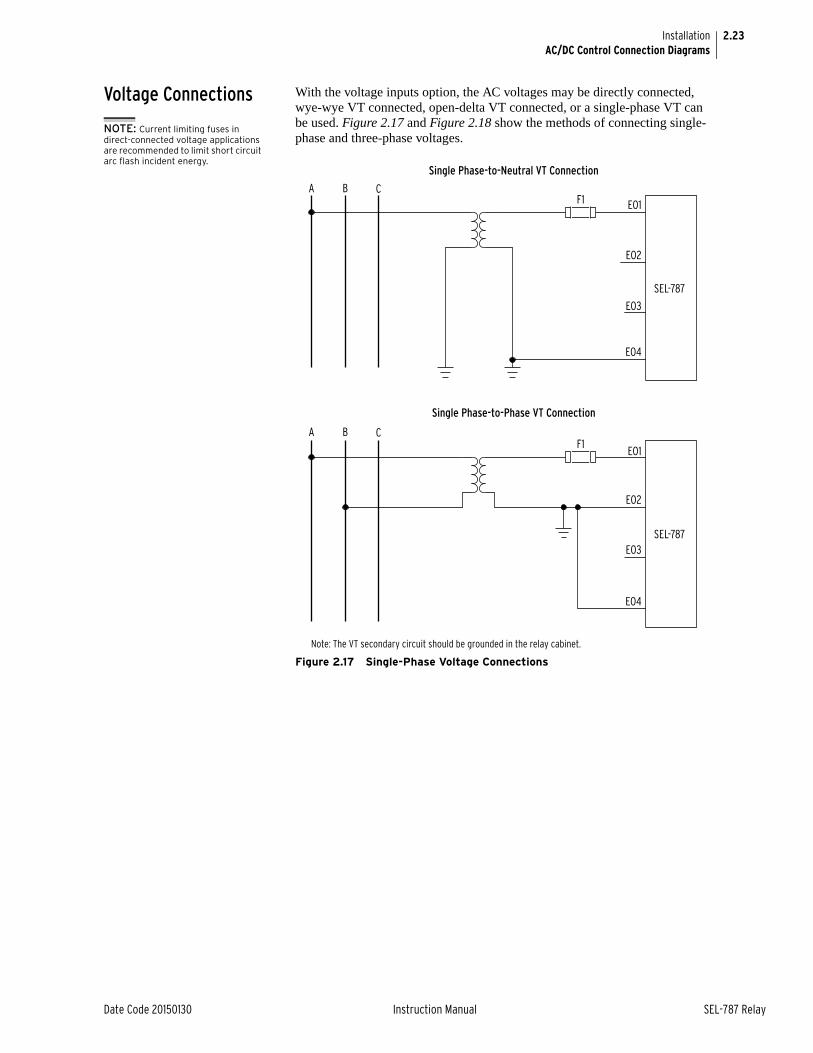
2.23
Date Code 20150130 Instruction Manual SEL-787 Relay
InstallationAC/DC Control Connection Diagrams
Voltage Connections With the voltage inputs option, the AC voltages may be directly connected, wye-wye VT connected, open-delta VT connected, or a single-phase VT can be used. Figure 2.17 and Figure 2.18 show the methods of connecting single-phase and three-phase voltages.
Figure 2.17 Single-Phase Voltage Connections
NOTE: Current limiting fuses in direct-connected voltage applications are recommended to limit short circuit arc flash incident energy.
A B C
EO1
EO2
EO3
EO4
Single Phase-to-Neutral VT Connection
Single Phase-to-Phase VT Connection
SEL-787
F1
A B CEO1
EO2
EO3
EO4
SEL-787
F1
Note: The VT secondary circuit should be grounded in the relay cabinet.
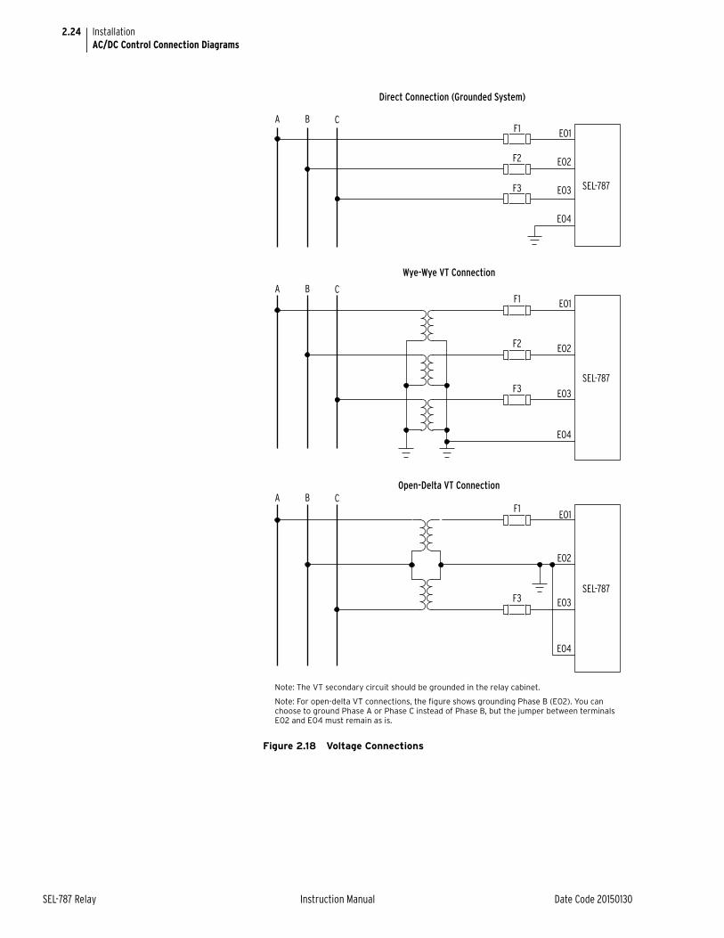
2.24
SEL-787 Relay Instruction Manual Date Code 20150130
InstallationAC/DC Control Connection Diagrams
Figure 2.18 Voltage Connections
Note: The VT secondary circuit should be grounded in the relay cabinet.
Note: For open-delta VT connections, the figure shows grounding Phase B (E02). You can choose to ground Phase A or Phase C instead of Phase B, but the jumper between terminals E02 and E04 must remain as is.
A B C
A B C
SEL-787
EO1
EO2
EO3
EO4
EO1
EO2
EO3
EO4
Direct Connection (Grounded System)
Wye-Wye VT Connection
Open-Delta VT Connection
F1
F2
F3
SEL-787
F1
F3
A B CEO1
EO2
EO3
EO4
SEL-787
F1
F2
F3
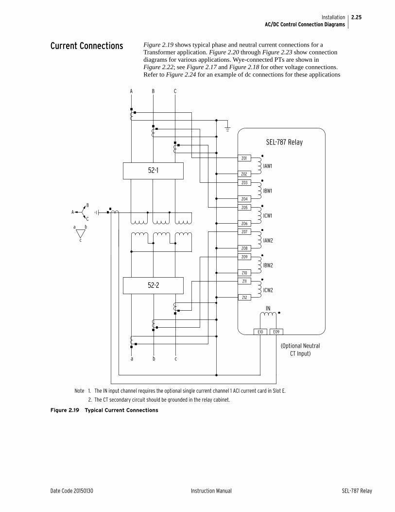
2.25
Date Code 20150130 Instruction Manual SEL-787 Relay
InstallationAC/DC Control Connection Diagrams
Current Connections Figure 2.19 shows typical phase and neutral current connections for a Transformer application. Figure 2.20 through Figure 2.23 show connection diagrams for various applications. Wye-connected PTs are shown in Figure 2.22; see Figure 2.17 and Figure 2.18 for other voltage connections. Refer to Figure 2.24 for an example of dc connections for these applications
Figure 2.19 Typical Current Connections
Note 1. The IN input channel requires the optional single current channel 1 ACI current card in Slot E.
2. The CT secondary circuit should be grounded in the relay cabinet.
IAW1
IBW1
ICW1
IAW2
IBW2
ICW2
SEL-787 Relay
52-1
52-2
A B C
a b c
IN
Z01
Z02
Z03
Z04
Z05
Z06
Z07
Z08
Z09
Z10
Z11
Z12
E10 E09
(Optional NeutralCT Input)
AB
C
a b
c
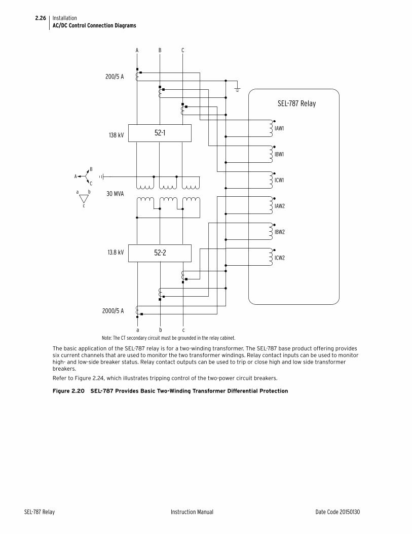
2.26
SEL-787 Relay Instruction Manual Date Code 20150130
InstallationAC/DC Control Connection Diagrams
The basic application of the SEL-787 relay is for a two-winding transformer. The SEL-787 base product offering provides six current channels that are used to monitor the two transformer windings. Relay contact inputs can be used to monitor high- and low-side breaker status. Relay contact outputs can be used to trip or close high and low side transformer breakers.
Refer to Figure 2.24, which illustrates tripping control of the two-power circuit breakers.
Figure 2.20 SEL-787 Provides Basic Two-Winding Transformer Differential Protection
IAW1
IBW1
ICW1
IAW2
IBW2
ICW2
SEL-787 Relay
52-1
52-2
A B C
a b c
200/5 A
138 kV
30 MVA
13.8 kV
2000/5 A
A B
C
a b
c
Note: The CT secondary circuit must be grounded in the relay cabinet.
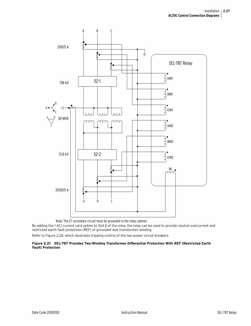
2.27
Date Code 20150130 Instruction Manual SEL-787 Relay
InstallationAC/DC Control Connection Diagrams
By adding the 1 ACI current card option to Slot E of the relay, the relay can be used to provide neutral overcurrent and restricted earth fault protection (REF) of grounded wye transformer winding.
Refer to Figure 2.24, which illustrates tripping control of the two-power circuit breakers.
Figure 2.21 SEL-787 Provides Two-Winding Transformer Differential Protection With REF (Restricted Earth Fault) Protection
IAW1
IBW1
ICW1
IAW2
IBW2
ICW2
SEL-787 Relay
52-1
52-2
A B C
a b c
IN
200/5 A
138 kV
30 MVA
13.8 kV
2000/5 A
A B
C
a b
c
Note: The CT secondary circuit must be grounded in the relay cabinet.
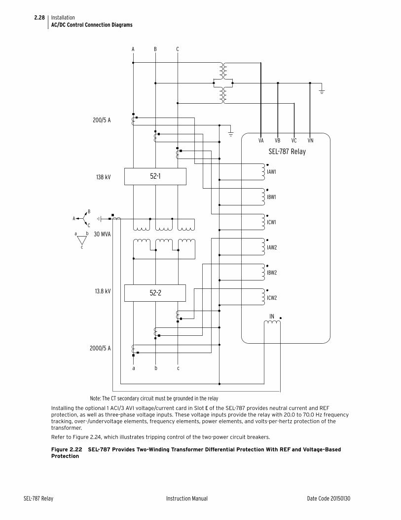
2.28
SEL-787 Relay Instruction Manual Date Code 20150130
InstallationAC/DC Control Connection Diagrams
Installing the optional 1 ACI/3 AVI voltage/current card in Slot E of the SEL-787 provides neutral current and REF protection, as well as three-phase voltage inputs. These voltage inputs provide the relay with 20.0 to 70.0 Hz frequency tracking, over-/undervoltage elements, frequency elements, power elements, and volts-per-hertz protection of the transformer.
Refer to Figure 2.24, which illustrates tripping control of the two-power circuit breakers.
Figure 2.22 SEL-787 Provides Two-Winding Transformer Differential Protection With REF and Voltage-Based Protection
VA VB VC VN
IAW1
IBW1
ICW1
IAW2
IBW2
ICW2
SEL-787 Relay
52-1
52-2
A B C
a b c
IN
A B
C
a b
c
200/5 A
138 kV
30 MVA
13.8 kV
2000/5 A
Note: The CT secondary circuit must be grounded in the relay
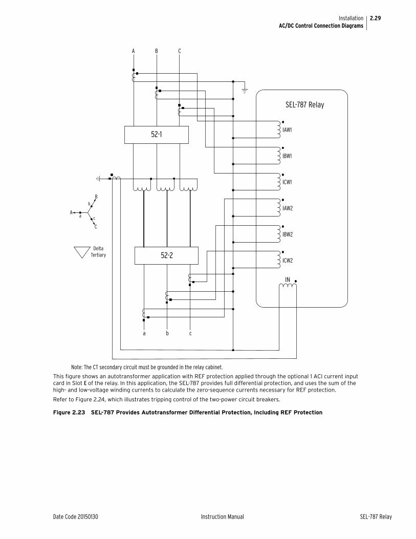
2.29
Date Code 20150130 Instruction Manual SEL-787 Relay
InstallationAC/DC Control Connection Diagrams
This figure shows an autotransformer application with REF protection applied through the optional 1 ACI current input card in Slot E of the relay. In this application, the SEL-787 provides full differential protection, and uses the sum of the high- and low-voltage winding currents to calculate the zero-sequence currents necessary for REF protection.
Refer to Figure 2.24, which illustrates tripping control of the two-power circuit breakers.
Figure 2.23 SEL-787 Provides Autotransformer Differential Protection, Including REF Protection
IAW1
IBW1
ICW1
IAW2
IBW2
ICW2
SEL-787 Relay
52-1
52-2
A B C
a b c
IN
A
B
C
a
Delta Tertiary
c
b
Note: The CT secondary circuit must be grounded in the relay cabinet.
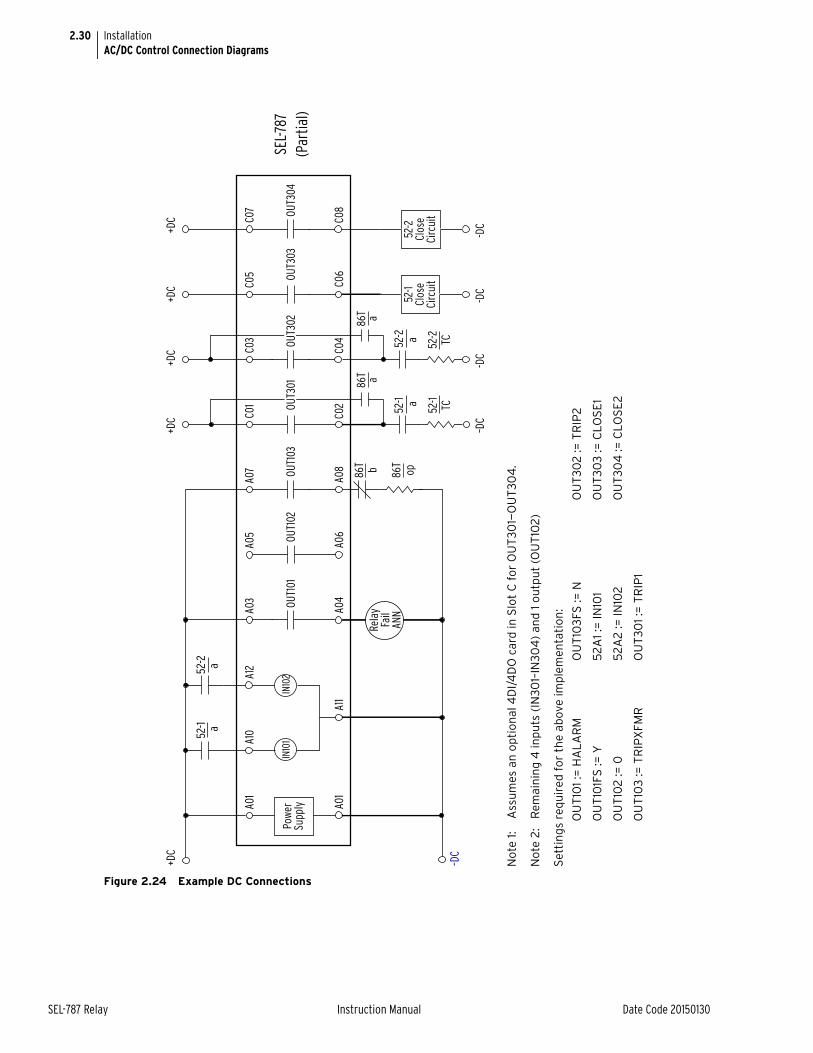
2.30
SEL-787 Relay Instruction Manual Date Code 20150130
InstallationAC/DC Control Connection Diagrams
Figure 2.24 Example DC Connections
A01
A10
A12
A03
A05
A07
C01
C03
C05
C07
52-1
52-2
a
a
A01
A11
A04
A06
A08
C02
C04
C06
C08
Rela
yFa
ilAN
N
IN10
1 IN
102
Pow
erSu
pply
86T b 86T
op
86T a
86T a
–DC
–DC
-DC
-DC
-DC
SEL-7
87(P
artia
l)
No
te 1
: A
ssu
mes
an
op
tio
nal
4D
I/4
DO
car
d in
Slo
t C
fo
r O
UT
301—
OU
T30
4.
No
te 2
: R
emai
nin
g 4
inp
uts
(IN
301–
IN30
4)
and
1 o
utp
ut
(OU
T10
2)
Set
tin
gs
req
uir
ed f
or
the
abov
e im
ple
men
tati
on
:
52-1
Clos
e Ci
rcui
t
52-2
Cl
ose
Circ
uit
52-1
52-2
a
a
52-1
52-2
TC
TC
+DC
+DC
+DC
+DC
+DC
OUT1
01
OUT1
02
OUT1
03
OUT3
01
OUT3
02OU
T303
OUT3
04
OU
T10
1 :=
HA
LA
RM
OU
T10
1FS
:= Y
OU
T10
2 :=
0
OU
T10
3 :=
TR
IPX
FMR
OU
T10
3FS
:= N
52
A1
:= IN
101
52
A2
:= IN
102
OU
T30
1 :=
TR
IP1
OU
T30
2 :=
TR
IP2
OU
T30
3 :=
CLO
SE
1
OU
T30
4 :=
CLO
SE
2
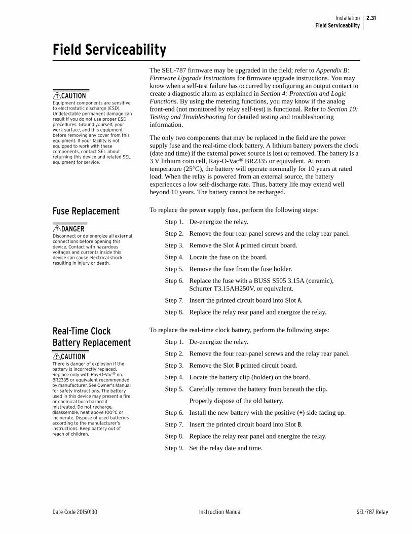
2.31
Date Code 20150130 Instruction Manual SEL-787 Relay
InstallationField Serviceability
Field ServiceabilityThe SEL-787 firmware may be upgraded in the field; refer to Appendix B: Firmware Upgrade Instructions for firmware upgrade instructions. You may know when a self-test failure has occurred by configuring an output contact to create a diagnostic alarm as explained in Section 4: Protection and Logic Functions. By using the metering functions, you may know if the analog front-end (not monitored by relay self-test) is functional. Refer to Section 10: Testing and Troubleshooting for detailed testing and troubleshooting information.
The only two components that may be replaced in the field are the power supply fuse and the real-time clock battery. A lithium battery powers the clock (date and time) if the external power source is lost or removed. The battery is a 3 V lithium coin cell, Ray-O-Vac® BR2335 or equivalent. At room temperature (25°C), the battery will operate nominally for 10 years at rated load. When the relay is powered from an external source, the battery experiences a low self-discharge rate. Thus, battery life may extend well beyond 10 years. The battery cannot be recharged.
Fuse Replacement To replace the power supply fuse, perform the following steps:
Step 1. De-energize the relay.
Step 2. Remove the four rear-panel screws and the relay rear panel.
Step 3. Remove the Slot A printed circuit board.
Step 4. Locate the fuse on the board.
Step 5. Remove the fuse from the fuse holder.
Step 6. Replace the fuse with a BUSS S505 3.15A (ceramic), Schurter T3.15AH250V, or equivalent.
Step 7. Insert the printed circuit board into Slot A.
Step 8. Replace the relay rear panel and energize the relay.
Real-Time Clock Battery Replacement
To replace the real-time clock battery, perform the following steps:
Step 1. De-energize the relay.
Step 2. Remove the four rear-panel screws and the relay rear panel.
Step 3. Remove the Slot B printed circuit board.
Step 4. Locate the battery clip (holder) on the board.
Step 5. Carefully remove the battery from beneath the clip.
Properly dispose of the old battery.
Step 6. Install the new battery with the positive (+) side facing up.
Step 7. Insert the printed circuit board into Slot B.
Step 8. Replace the relay rear panel and energize the relay.
Step 9. Set the relay date and time.
CAUTIONEquipment components are sensitive to electrostatic discharge (ESD). Undetectable permanent damage can result if you do not use proper ESD procedures. Ground yourself, your work surface, and this equipment before removing any cover from this equipment. If your facility is not equipped to work with these components, contact SEL about returning this device and related SEL equipment for service.
DANGERDisconnect or de-energize all external connections before opening this device. Contact with hazardous voltages and currents inside this device can cause electrical shock resulting in injury or death.
CAUTIONThere is danger of explosion if the battery is incorrectly replaced. Replace only with Ray-O-Vac® no. BR2335 or equivalent recommended by manufacturer. See Owner's Manual for safety instructions. The battery used in this device may present a fire or chemical burn hazard if mistreated. Do not recharge, disassemble, heat above 100°C or incinerate. Dispose of used batteries according to the manufacturer’s instructions. Keep battery out of reach of children.

This page intentionally left blank

Date Code 20150130 Instruction Manual SEL-787 Relay
Section 3PC Software
Instruction Manual
OverviewSEL provides many PC software solutions (applications) to support the SEL-787 and other SEL devices. Table 3.1 lists SEL-787 software solutions.
This section describes how to get started with the SEL-787 and ACSELERATOR QuickSet SEL-5030 Software. ACSELERATOR QuickSet is a powerful setting, event analysis, and measurement tool that aids in setting, applying, and using the SEL-787. Table 3.2 shows the suite of ACSELERATOR QuickSet applications provided for the SEL-787.
Table 3.1 SEL Software Solutions
Part Number
Product Name Description
SEL-5010 SEL-5010 Relay Assistant Software Manages a connection directory and settings of multiple devices.
SEL-5030 ACSELERATOR QuickSet® SEL-5030 Software See Table 3.2.
SEL-5032 ACSELERATOR Architect® SEL-5032 Software Configures IEC 61850 communications.
SEL-5040 ACSELERATOR Report Server™ SEL-5040 Software Automatically retrieves, files, and summarizes reports.
SEL-5601 ACSELERATOR Analytic Assistant™ SEL-5601 Software Converts SEL Compressed ASCII event report files to oscillography.
SEL-5801 SEL-5801 Cable Selector Software Selects the proper SEL cables for your application.
SEL-5806 SEL-5806 Volts/Hertz User Curve Designer PC Software Designs user-defined, volts/Hz inverse-time characteristic curve to match any transformer characteristic (refer to Section 4: Protection and Logic Functions).
Table 3.2 ACSELERATOR QuickSet SEL-5030 Software
Application Description
Rules-Based Settings Editor Provides on-line or off-line device settings that include interdependency checks. Use this feature to create and manage settings for multiple devices in a database.
HMI Provides a summary view of device operation. Use this feature to simplify commissioning,
Design Templates (Available in licensed versions of ACSELERATOR QuickSet)
Allows you to customize relay settings to particular applications and store those settings in Design Templates. You can lock settings to match your standards or lock and hide settings that are not used.
Event Analysis Provides oscillography and other event analysis tools.
Settings Database Management ACSELERATOR QuickSet uses a database to manage the settings of multiple devices.
Terminal Provides a direct connection to the SEL device. Use this feature to ensure proper communications and directly interface with the device.
Help Provides general ACSELERATOR QuickSet and device-specific ACSELERATOR QuickSet context.
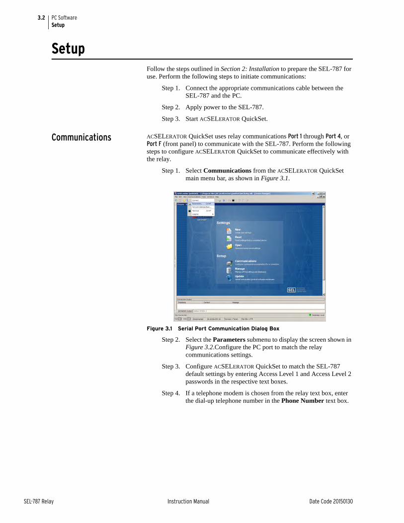
3.2
SEL-787 Relay Instruction Manual Date Code 20150130
PC SoftwareSetup
SetupFollow the steps outlined in Section 2: Installation to prepare the SEL-787 for use. Perform the following steps to initiate communications:
Step 1. Connect the appropriate communications cable between the SEL-787 and the PC.
Step 2. Apply power to the SEL-787.
Step 3. Start ACSELERATOR QuickSet.
Communications ACSELERATOR QuickSet uses relay communications Port 1 through Port 4, or Port F (front panel) to communicate with the SEL-787. Perform the following steps to configure ACSELERATOR QuickSet to communicate effectively with the relay.
Step 1. Select Communications from the ACSELERATOR QuickSet main menu bar, as shown in Figure 3.1.
Figure 3.1 Serial Port Communication Dialog Box
Step 2. Select the Parameters submenu to display the screen shown in Figure 3.2.Configure the PC port to match the relay communications settings.
Step 3. Configure ACSELERATOR QuickSet to match the SEL-787 default settings by entering Access Level 1 and Access Level 2 passwords in the respective text boxes.
Step 4. If a telephone modem is chosen from the relay text box, enter the dial-up telephone number in the Phone Number text box.
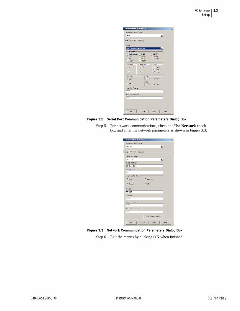
3.3
Date Code 20150130 Instruction Manual SEL-787 Relay
PC SoftwareSetup
Figure 3.2 Serial Port Communication Parameters Dialog Box
Step 5. For network communications, check the Use Network check box and enter the network parameters as shown in Figure 3.3.
Figure 3.3 Network Communication Parameters Dialog Box
Step 6. Exit the menus by clicking OK when finished.
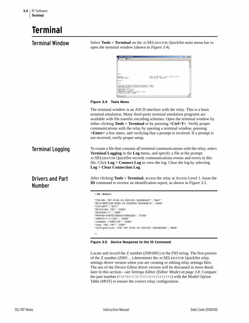
3.4
SEL-787 Relay Instruction Manual Date Code 20150130
PC SoftwareTerminal
TerminalTerminal Window Select Tools > Terminal on the ACSELERATOR QuickSet main menu bar to
open the terminal window (shown in Figure 3.4).
Figure 3.4 Tools Menu
The terminal window is an ASCII interface with the relay. This is a basic terminal emulation. Many third-party terminal emulation programs are available with file transfer encoding schemes. Open the terminal window by either clicking Tools > Terminal or by pressing <Ctrl+T>. Verify proper communications with the relay by opening a terminal window, pressing <Enter> a few times, and verifying that a prompt is received. If a prompt is not received, verify proper setup.
Terminal Logging To create a file that contains all terminal communications with the relay, select Terminal Logging in the Log menu, and specify a file at the prompt. ACSELERATOR QuickSet records communications events and errors in this file. Click Log > Connect Log to view the log. Clear the log by selecting Log > Clear Connection Log.
Drivers and Part Number
After clicking Tools > Terminal, access the relay at Access Level 1. Issue the ID command to receive an identification report, as shown in Figure 3.5.
Locate and record the Z number (Z001001) in the FID string. The first portion of the Z number (Z001…) determines the ACSELERATOR QuickSet relay settings driver version when you are creating or editing relay settings files. The use of the Device Editor driver version will be discussed in more detail later in this section—see Settings Editor (Editor Mode) on page 3.8. Compare the part number (PARTNO=0787XXXXXXXXXXXXXXXX) with the Model Option Table (MOT) to ensure the correct relay configuration.
=>ID <Enter>
"FID=SEL-787-R100-V0-Z001001-D20080407","0947""BFID=BOOTLDR-R303-V0-Z000000-D20060612","0949""CID=26FF","0271""DEVID=SEL-787","03D0""DEVCODE=71","030F""PARTNO=0787EX1B0X0X7585023X","073D""CONFIG=11111201","03EB""iedName =TEMPLATE","0380""type =SEL-787","028F""configVersion =ICD-787-R100-V0-Z001001-D20080326","0629"
=>
Figure 3.5 Device Response to the ID Command
3.5
Date Code 20150130 Instruction Manual SEL-787 Relay
PC SoftwareSettings Database Management and Drivers
Settings Database Management and DriversACSELERATOR QuickSet uses a database to save relay settings. ACSELERATOR QuickSet contains sets of all settings files for each relay specified in the Database Manager. Choose appropriate storage backup methods and a secure location for storing database files.
Database Manager Select File > Database Manager on the main menu bar to create new databases and manage records within existing databases.
Settings Database
Step 1. Open the Database Manager to access the database. Click File > Database Manager. A dialog box appears.
The default database file already configured in ACSELERATOR QuickSet is Relay.rdb. This database contains example settings files for the SEL products with which you can use ACSELERATOR QuickSet.
Step 2. Enter descriptions for the database and for each relay or relay in the database in the Database Description and Settings Description dialog boxes.
Step 3. Enter special operating characteristics that describe the relay settings in the Settings Description dialog box. These can include the protection scheme settings and communications settings.
Step 4. Highlight one of the relays listed in Settings in Database and select the Copy option button to create a new collection of settings.
ACSELERATOR QuickSet prompts for a new name. Be sure to enter a new description in Settings Description.
Copy/Move Settings Between Databases
Step 1. Select the Copy/Move Settings Between Databases tab to create multiple databases with the Database Manager; these databases are useful for grouping similar protection schemes or geographic areas.
Step 2. Click the Open B option button to open a relay database.
Step 3. Type a filename and click Open.
a. Highlight a device or settings file in Settings Database A.
b. Select Copy or Move, and click the > button to create a new device or settings file in Settings Database B.
Step 4. Reverse this process to take a device or settings file from Settings Database B to Settings Database A. Copy creates an identical device or settings file that appears in both databases. Move removes the device or settings file from one database and places the device or settings file in another database.
3.6
SEL-787 Relay Instruction Manual Date Code 20150130
PC SoftwareSettings
Create a New Database, Copy an Existing DatabaseTo create and copy an existing database of devices to a new database:
Step 1. Click File > Database Manager, and select the New button. ACSELERATOR QuickSet prompts you for a file name.
Step 2. Type the new database name (and location if the new location differs from the existing one), and click Save. ACSELERATOR QuickSet displays the message Settings [path and filename] was successfully created.
Step 3. Click OK.
To copy an exiting database of devices to a new database:
Step 1. Click File > Database Manager, and select the Copy/Move Settings Between Databases tab in the Database Manager dialog box.
ACSELERATOR QuickSet opens the last active database and assigns it as Settings Database A.
Step 2. Click the Settings Database B button; ACSELERATOR QuickSet prompts you for a file location.
Step 3. Type a new database name, click the Open button.
SettingsACSELERATOR QuickSet offers the capability of creating settings for one or more SEL-787 relays. Store existing relay settings downloaded from SEL-787 relays with ACSELERATOR QuickSet, creating a library of relay settings, then modify and upload these settings from the settings library to an SEL-787. ACSELERATOR QuickSet makes setting the relay easy and efficient. However, you do not have to use ACSELERATOR QuickSet to configure the SEL-787; you can use an ASCII terminal or a computer running terminal emulation software. ACSELERATOR QuickSet provides the advantages of rules-based settings checks, SELOGIC® control equation Expression Builder, operator control and metering HMI, event analysis, and help.
Settings Editor The Settings Editor shows the relay settings in easy-to-understand categories. The SEL-787 settings structure makes setting the relay easy and efficient. Settings are grouped logically, and relay elements that are not used in the selected protection scheme are not accessible. For example, if there is only one analog card installed in the relay, you can access settings for this one card only. Settings for the other slots are dimmed (grayed) in the ACSELERATOR QuickSet menus. ACSELERATOR QuickSet shows all of the settings categories in the settings tree view. The settings tree view remains constant whether settings categories are enabled or disabled. However, any disabled settings are dimmed when accessed by clicking an item in the tree view.
Settings Menu ACSELERATOR QuickSet uses a database to store and manage SEL relay settings. Each unique relay has its own record of settings. Use the File menu to Open an existing record, create and open a New record, or Read relay settings from a connected SEL-787 and then create and open a new record. Use Tools menu to Convert and open an existing record. The record will be opened in the Setting Editor as a Setting Form (template) or in Editor Mode.
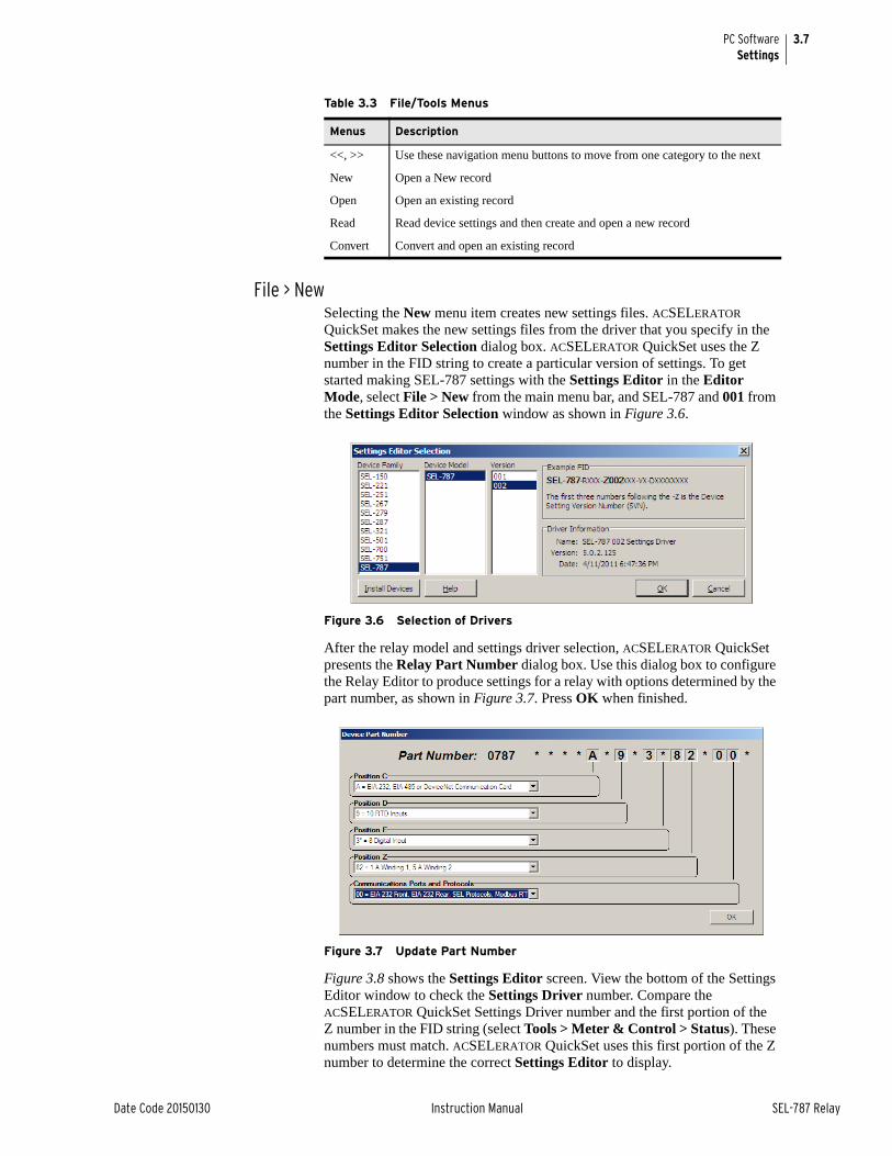
3.7
Date Code 20150130 Instruction Manual SEL-787 Relay
PC SoftwareSettings
File > NewSelecting the New menu item creates new settings files. ACSELERATOR QuickSet makes the new settings files from the driver that you specify in the Settings Editor Selection dialog box. ACSELERATOR QuickSet uses the Z number in the FID string to create a particular version of settings. To get started making SEL-787 settings with the Settings Editor in the Editor Mode, select File > New from the main menu bar, and SEL-787 and 001 from the Settings Editor Selection window as shown in Figure 3.6.
Figure 3.6 Selection of Drivers
After the relay model and settings driver selection, ACSELERATOR QuickSet presents the Relay Part Number dialog box. Use this dialog box to configure the Relay Editor to produce settings for a relay with options determined by the part number, as shown in Figure 3.7. Press OK when finished.
Figure 3.7 Update Part Number
Figure 3.8 shows the Settings Editor screen. View the bottom of the Settings Editor window to check the Settings Driver number. Compare the ACSELERATOR QuickSet Settings Driver number and the first portion of the Z number in the FID string (select Tools > Meter & Control > Status). These numbers must match. ACSELERATOR QuickSet uses this first portion of the Z number to determine the correct Settings Editor to display.
Table 3.3 File/Tools Menus
Menus Description
<<, >> Use these navigation menu buttons to move from one category to the next
New Open a New record
Open Open an existing record
Read Read device settings and then create and open a new record
Convert Convert and open an existing record
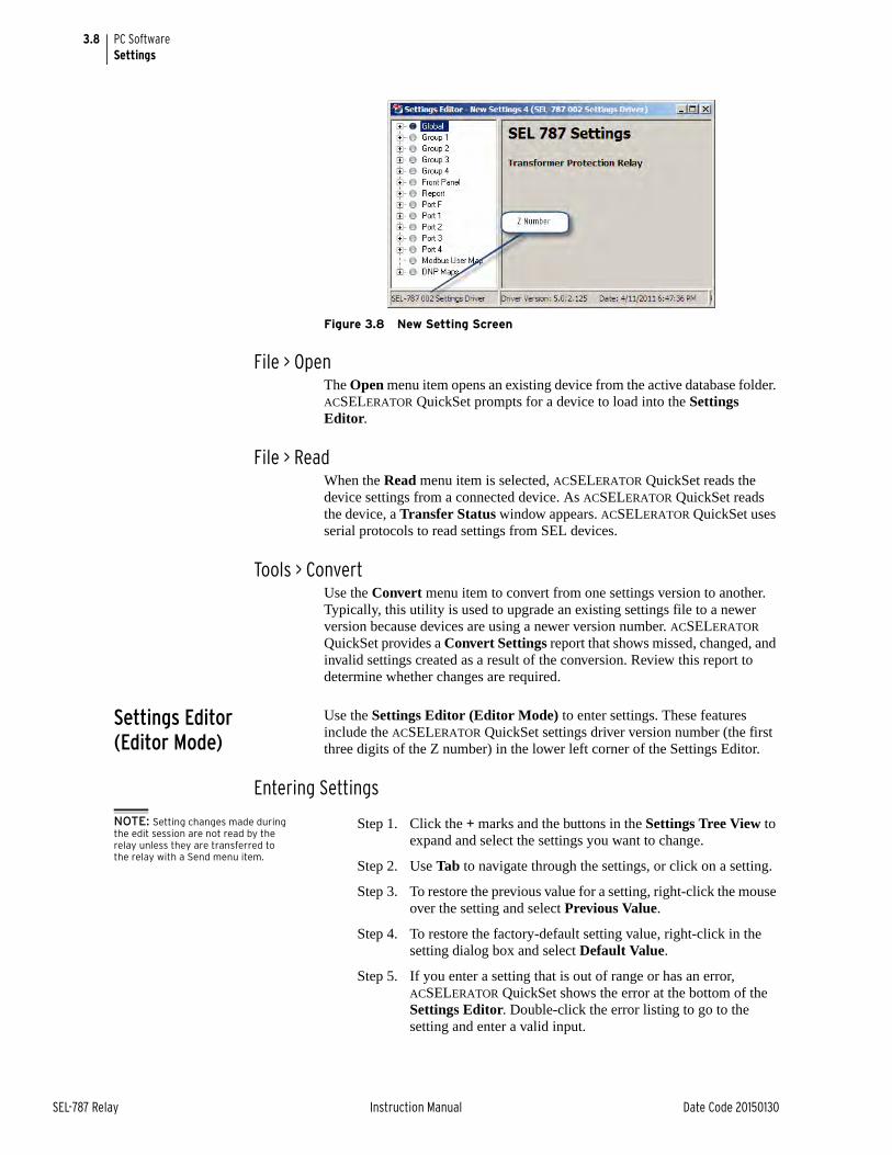
3.8
SEL-787 Relay Instruction Manual Date Code 20150130
PC SoftwareSettings
Figure 3.8 New Setting Screen
File > OpenThe Open menu item opens an existing device from the active database folder. ACSELERATOR QuickSet prompts for a device to load into the Settings Editor.
File > ReadWhen the Read menu item is selected, ACSELERATOR QuickSet reads the device settings from a connected device. As ACSELERATOR QuickSet reads the device, a Transfer Status window appears. ACSELERATOR QuickSet uses serial protocols to read settings from SEL devices.
Tools > ConvertUse the Convert menu item to convert from one settings version to another. Typically, this utility is used to upgrade an existing settings file to a newer version because devices are using a newer version number. ACSELERATOR QuickSet provides a Convert Settings report that shows missed, changed, and invalid settings created as a result of the conversion. Review this report to determine whether changes are required.
Settings Editor (Editor Mode)
Use the Settings Editor (Editor Mode) to enter settings. These features include the ACSELERATOR QuickSet settings driver version number (the first three digits of the Z number) in the lower left corner of the Settings Editor.
Entering Settings
NOTE: Setting changes made during the edit session are not read by the relay unless they are transferred to the relay with a Send menu item.
Step 1. Click the + marks and the buttons in the Settings Tree View to expand and select the settings you want to change.
Step 2. Use Tab to navigate through the settings, or click on a setting.
Step 3. To restore the previous value for a setting, right-click the mouse over the setting and select Previous Value.
Step 4. To restore the factory-default setting value, right-click in the setting dialog box and select Default Value.
Step 5. If you enter a setting that is out of range or has an error, ACSELERATOR QuickSet shows the error at the bottom of the Settings Editor. Double-click the error listing to go to the setting and enter a valid input.
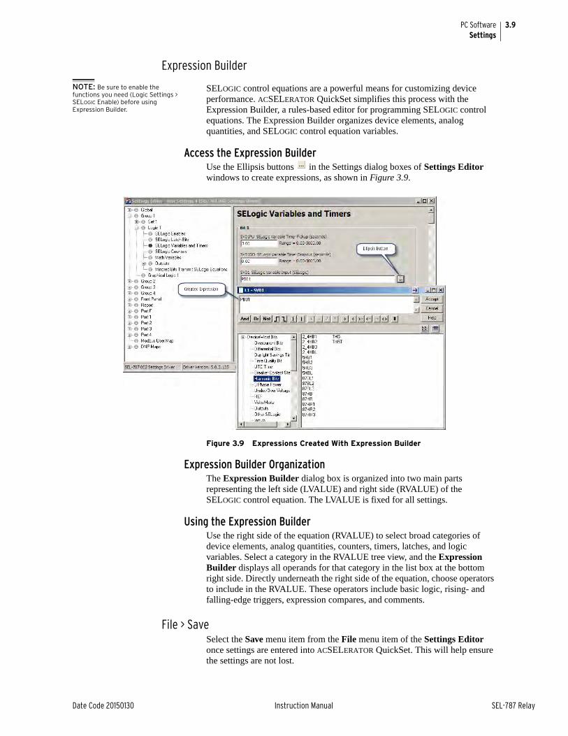
3.9
Date Code 20150130 Instruction Manual SEL-787 Relay
PC SoftwareSettings
Expression Builder
NOTE: Be sure to enable the functions you need (Logic Settings > SELOGIC Enable) before using Expression Builder.
SELOGIC control equations are a powerful means for customizing device performance. ACSELERATOR QuickSet simplifies this process with the Expression Builder, a rules-based editor for programming SELOGIC control equations. The Expression Builder organizes device elements, analog quantities, and SELOGIC control equation variables.
Access the Expression BuilderUse the Ellipsis buttons in the Settings dialog boxes of Settings Editor windows to create expressions, as shown in Figure 3.9.
Figure 3.9 Expressions Created With Expression Builder
Expression Builder OrganizationThe Expression Builder dialog box is organized into two main parts representing the left side (LVALUE) and right side (RVALUE) of the SELOGIC control equation. The LVALUE is fixed for all settings.
Using the Expression BuilderUse the right side of the equation (RVALUE) to select broad categories of device elements, analog quantities, counters, timers, latches, and logic variables. Select a category in the RVALUE tree view, and the Expression Builder displays all operands for that category in the list box at the bottom right side. Directly underneath the right side of the equation, choose operators to include in the RVALUE. These operators include basic logic, rising- and falling-edge triggers, expression compares, and comments.
File > SaveSelect the Save menu item from the File menu item of the Settings Editor once settings are entered into ACSELERATOR QuickSet. This will help ensure the settings are not lost.
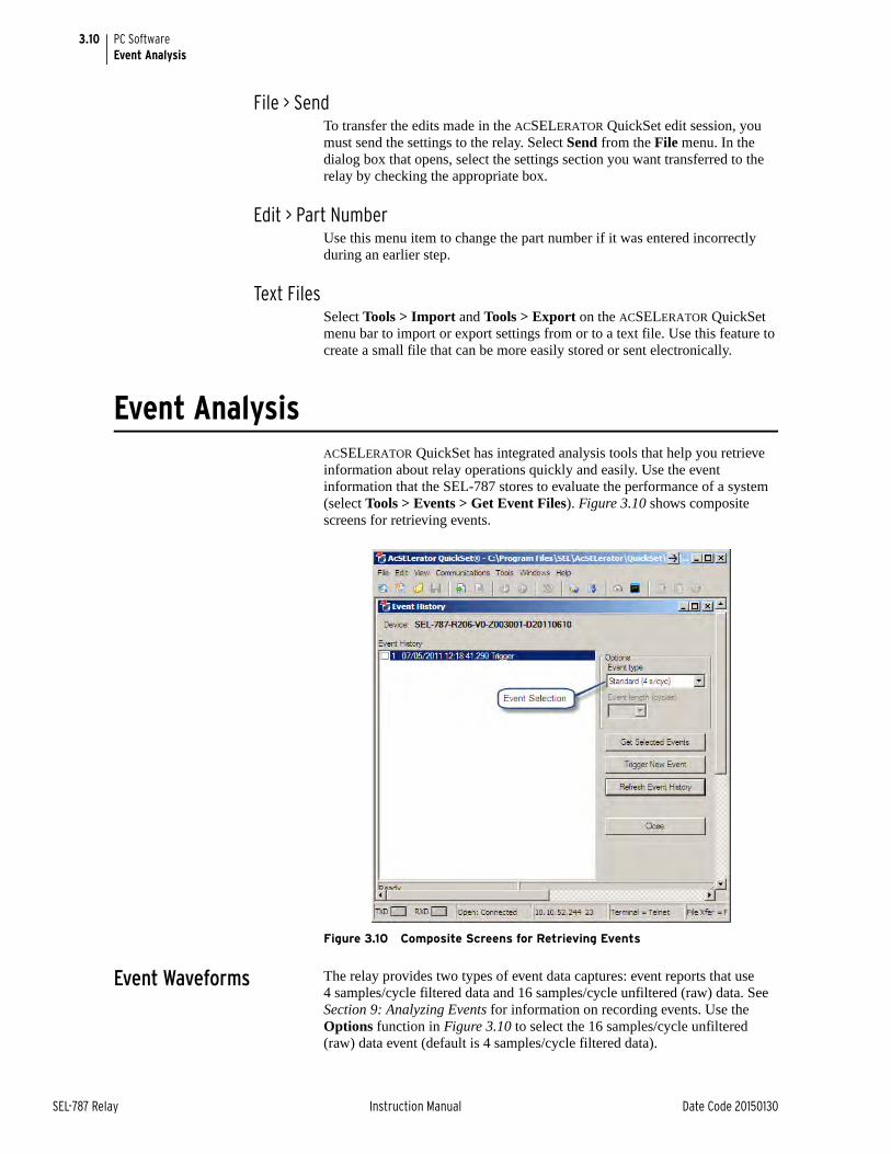
3.10
SEL-787 Relay Instruction Manual Date Code 20150130
PC SoftwareEvent Analysis
File > SendTo transfer the edits made in the ACSELERATOR QuickSet edit session, you must send the settings to the relay. Select Send from the File menu. In the dialog box that opens, select the settings section you want transferred to the relay by checking the appropriate box.
Edit > Part NumberUse this menu item to change the part number if it was entered incorrectly during an earlier step.
Text FilesSelect Tools > Import and Tools > Export on the ACSELERATOR QuickSet menu bar to import or export settings from or to a text file. Use this feature to create a small file that can be more easily stored or sent electronically.
Event AnalysisACSELERATOR QuickSet has integrated analysis tools that help you retrieve information about relay operations quickly and easily. Use the event information that the SEL-787 stores to evaluate the performance of a system (select Tools > Events > Get Event Files). Figure 3.10 shows composite screens for retrieving events.
Figure 3.10 Composite Screens for Retrieving Events
Event Waveforms The relay provides two types of event data captures: event reports that use 4 samples/cycle filtered data and 16 samples/cycle unfiltered (raw) data. See Section 9: Analyzing Events for information on recording events. Use the Options function in Figure 3.10 to select the 16 samples/cycle unfiltered (raw) data event (default is 4 samples/cycle filtered data).
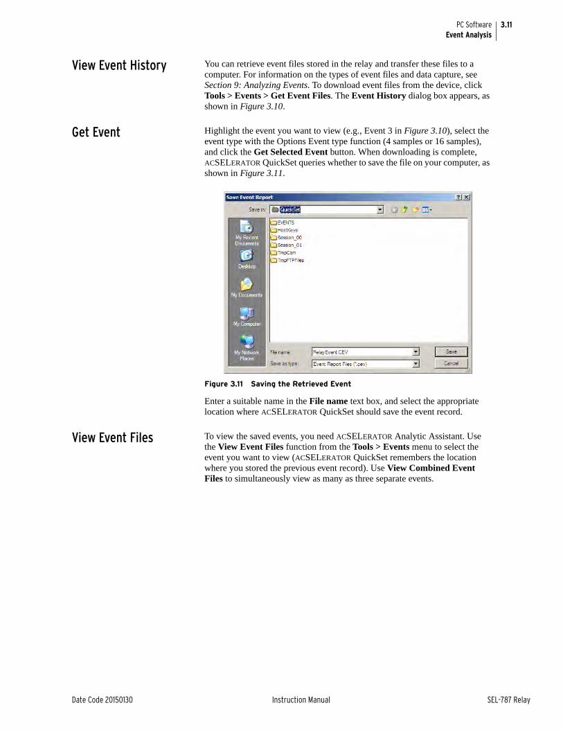
3.11
Date Code 20150130 Instruction Manual SEL-787 Relay
PC SoftwareEvent Analysis
View Event History You can retrieve event files stored in the relay and transfer these files to a computer. For information on the types of event files and data capture, see Section 9: Analyzing Events. To download event files from the device, click Tools > Events > Get Event Files. The Event History dialog box appears, as shown in Figure 3.10.
Get Event Highlight the event you want to view (e.g., Event 3 in Figure 3.10), select the event type with the Options Event type function (4 samples or 16 samples), and click the Get Selected Event button. When downloading is complete, ACSELERATOR QuickSet queries whether to save the file on your computer, as shown in Figure 3.11.
Figure 3.11 Saving the Retrieved Event
Enter a suitable name in the File name text box, and select the appropriate location where ACSELERATOR QuickSet should save the event record.
View Event Files To view the saved events, you need ACSELERATOR Analytic Assistant. Use the View Event Files function from the Tools > Events menu to select the event you want to view (ACSELERATOR QuickSet remembers the location where you stored the previous event record). Use View Combined Event Files to simultaneously view as many as three separate events.
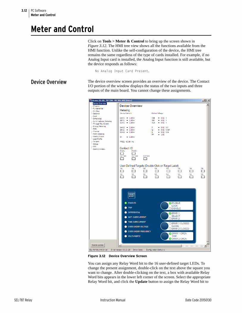
3.12
SEL-787 Relay Instruction Manual Date Code 20150130
PC SoftwareMeter and Control
Meter and ControlClick on Tools > Meter & Control to bring up the screen shown in Figure 3.12. The HMI tree view shows all the functions available from the HMI function. Unlike the self-configuration of the device, the HMI tree remains the same regardless of the type of cards installed. For example, if no Analog Input card is installed, the Analog Input function is still available, but the device responds as follows:
No Analog Input Card Present.
Device Overview The device overview screen provides an overview of the device. The Contact I/O portion of the window displays the status of the two inputs and three outputs of the main board. You cannot change these assignments.
Figure 3.12 Device Overview Screen
You can assign any Relay Word bit to the 16 user-defined target LEDs. To change the present assignment, double-click on the text above the square you want to change. After double-clicking on the text, a box with available Relay Word bits appears in the lower left corner of the screen. Select the appropriate Relay Word bit, and click the Update button to assign the Relay Word bit to
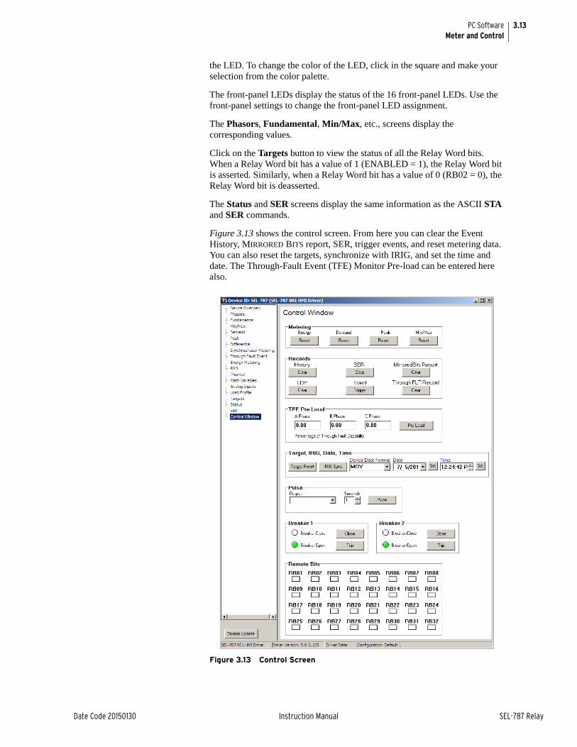
3.13
Date Code 20150130 Instruction Manual SEL-787 Relay
PC SoftwareMeter and Control
the LED. To change the color of the LED, click in the square and make your selection from the color palette.
The front-panel LEDs display the status of the 16 front-panel LEDs. Use the front-panel settings to change the front-panel LED assignment.
The Phasors, Fundamental, Min/Max, etc., screens display the corresponding values.
Click on the Targets button to view the status of all the Relay Word bits. When a Relay Word bit has a value of 1 (ENABLED = 1), the Relay Word bit is asserted. Similarly, when a Relay Word bit has a value of 0 (RB02 = 0), the Relay Word bit is deasserted.
The Status and SER screens display the same information as the ASCII STA and SER commands.
Figure 3.13 shows the control screen. From here you can clear the Event History, MIRRORED BITS report, SER, trigger events, and reset metering data. You can also reset the targets, synchronize with IRIG, and set the time and date. The Through-Fault Event (TFE) Monitor Pre-load can be entered here also.
Figure 3.13 Control Screen
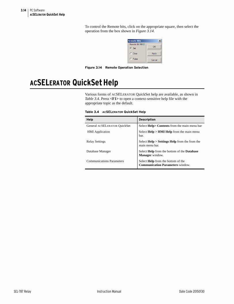
3.14
SEL-787 Relay Instruction Manual Date Code 20150130
PC SoftwareACSELERATOR QuickSet Help
To control the Remote bits, click on the appropriate square, then select the operation from the box shown in Figure 3.14.
Figure 3.14 Remote Operation Selection
ACSELERATOR QuickSet HelpVarious forms of ACSELERATOR QuickSet help are available, as shown in Table 3.4. Press <F1> to open a context-sensitive help file with the appropriate topic as the default.
Table 3.4 ACSELERATOR QuickSet Help
Help Description
General ACSELERATOR QuickSet Select Help> Contents from the main menu bar
HMI Application Select Help > HMI Help from the main menu bar.
Relay Settings Select Help > Settings Help from the from the main menu bar.
Database Manager Select Help from the bottom of the Database Manager window.
Communications Parameters Select Help from the bottom of the Communication Parameters window.
Date Code 20150130 Instruction Manual SEL-787 Relay
Section 4Protection and Logic Functions
Instruction Manual
Overview
NOTE: Each SEL-787 is shipped with default factory settings. Calculate the settings for your application to ensure secure and dependable protection. Document and enter the settings (see Section 6: Settings).
This section describes the SEL-787 Transformer Protection Relay settings, including the protection elements and basic functions, control I/O logic, as well as the settings that control the communications ports and front-panel displays.
This section includes the following subsections:
Application Data. Lists information that you will need to know about the protected equipment before calculating the relay settings.
Group Settings (SET Command). Lists settings that configure the relay inputs to accurately measure and interpret the ac current and optional voltage input signals.
Basic Protection. Lists settings for the differential, optional restricted earth fault, and the overcurrent protection elements.
RTD-Based Protection. Lists settings associated with the RTD inputs. You can skip this subsection if your application does not include RTD inputs.
Voltage-Based Protection. Lists settings associated with the optional ac voltage-based protection elements. You can skip this subsection if your relay is not equipped with optional voltage inputs.
Demand Metering. Lists settings associated with demand metering.
Trip/Close Logic. Lists Trip and Close logic.
Logic Settings (SET L Command). Lists settings associated with latches, timers, and output contacts.
Global Settings (SET G Command). Lists settings that allow you to configure the relay to your power system, date format, analog inputs/outputs, and logic equations of global nature.
Port Settings (SET P Command). Lists settings that configure the relay front and rear ports.
Front-Panel Settings (SET F Command). Lists settings for the front-panel display, pushbuttons, and LED control.
Report Settings (SET R Command). Lists settings for the sequential event reports, event reports, and load profile reports.
DNP Map Settings (SET DNP n Command, n = 1, 2, or 3). Shows DNP user map register settings.
Modbus Map Settings (SET M Command). Shows Modbus® user map register settings.
4.2
SEL-787 Relay Instruction Manual Date Code 20150130
Protection and Logic FunctionsApplication Data
When you calculate the protection element settings, proceed through the subsections listed earlier. Skip the RTD, voltage-based, and frequency protection subsections if they do not apply to your specific relay model or installation. See Section 6: Settings for the list of all settings (SEL-787 Settings Sheets) and various methods of accessing them. All current and voltage settings in the SEL-787 are in secondary.
NOTE: The DeviceNet port parameters can only be set at the rear of the relay on the DeviceNet card (see Figure G.1).
You can enter the settings by using the front-panel SET RELAY function (see Section 8: Front-Panel Operations), the serial ports (see Section 7: Communications), the DeviceNet port (see Appendix G: DeviceNet Communications), or the Ethernet port (see Section 7: Communications).
Application DataIt is faster and easier for you to calculate settings for the SEL-787 if you collect the following information before you begin:
➤ Power transformer data: MVA rating, winding configurations and voltages, impedance, etc.
➤ Highest expected load current
➤ Current transformer primary and secondary ratings and connections
➤ System phase rotation and nominal frequency
➤ Voltage transformer ratios and connections, if used
➤ Type and location of resistance temperature devices (RTDs), if used
➤ Expected fault current magnitudes for ground and three-phase faults
Group Settings (SET Command)ID Settings All models of the SEL-787 have the identifier settings described in Table 4.1.
The SEL-787 prints the Relay and Terminal Identifier strings at the top of the responses to serial port commands to identify messages from individual relays.
Enter as many as 16 characters, including letters A–Z (not case sensitive), numbers 0–9, periods (.), dashes (-), and spaces. Suggested identifiers include the location or number of the protected transformer.
NOTE: The terms winding and terminal are used interchangeably in this manual.
Table 4.1 Identifier Settings
Setting Prompt Setting RangeSetting Name := Factory Default
UNIT ID LINE 1 16 Characters RID := SEL-787
UNIT ID LINE 2 16 Characters TID := TRNSFRMR RELAY
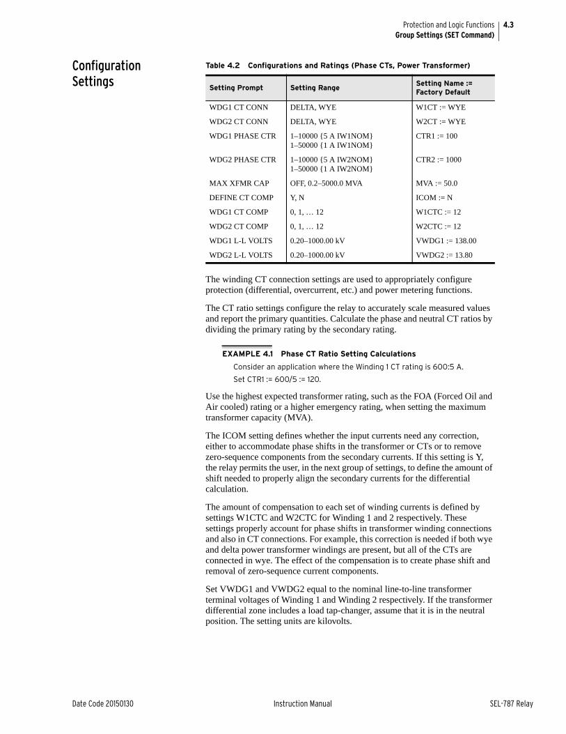
4.3
Date Code 20150130 Instruction Manual SEL-787 Relay
Protection and Logic FunctionsGroup Settings (SET Command)
Configuration Settings
The winding CT connection settings are used to appropriately configure protection (differential, overcurrent, etc.) and power metering functions.
The CT ratio settings configure the relay to accurately scale measured values and report the primary quantities. Calculate the phase and neutral CT ratios by dividing the primary rating by the secondary rating.
EXAMPLE 4.1 Phase CT Ratio Setting Calculations
Consider an application where the Winding 1 CT rating is 600:5 A.
Set CTR1 := 600/5 := 120.
Use the highest expected transformer rating, such as the FOA (Forced Oil and Air cooled) rating or a higher emergency rating, when setting the maximum transformer capacity (MVA).
The ICOM setting defines whether the input currents need any correction, either to accommodate phase shifts in the transformer or CTs or to remove zero-sequence components from the secondary currents. If this setting is Y, the relay permits the user, in the next group of settings, to define the amount of shift needed to properly align the secondary currents for the differential calculation.
The amount of compensation to each set of winding currents is defined by settings W1CTC and W2CTC for Winding 1 and 2 respectively. These settings properly account for phase shifts in transformer winding connections and also in CT connections. For example, this correction is needed if both wye and delta power transformer windings are present, but all of the CTs are connected in wye. The effect of the compensation is to create phase shift and removal of zero-sequence current components.
Set VWDG1 and VWDG2 equal to the nominal line-to-line transformer terminal voltages of Winding 1 and Winding 2 respectively. If the transformer differential zone includes a load tap-changer, assume that it is in the neutral position. The setting units are kilovolts.
Table 4.2 Configurations and Ratings (Phase CTs, Power Transformer)
Setting Prompt Setting RangeSetting Name := Factory Default
WDG1 CT CONN DELTA, WYE W1CT := WYE
WDG2 CT CONN DELTA, WYE W2CT := WYE
WDG1 PHASE CTR 1–10000 {5 A IW1NOM} 1–50000 {1 A IW1NOM}
CTR1 := 100
WDG2 PHASE CTR 1–10000 {5 A IW2NOM} 1–50000 {1 A IW2NOM}
CTR2 := 1000
MAX XFMR CAP OFF, 0.2–5000.0 MVA MVA := 50.0
DEFINE CT COMP Y, N ICOM := N
WDG1 CT COMP 0, 1, … 12 W1CTC := 12
WDG2 CT COMP 0, 1, … 12 W2CTC := 12
WDG1 L-L VOLTS 0.20–1000.00 kV VWDG1 := 138.00
WDG2 L-L VOLTS 0.20–1000.00 kV VWDG2 := 13.80
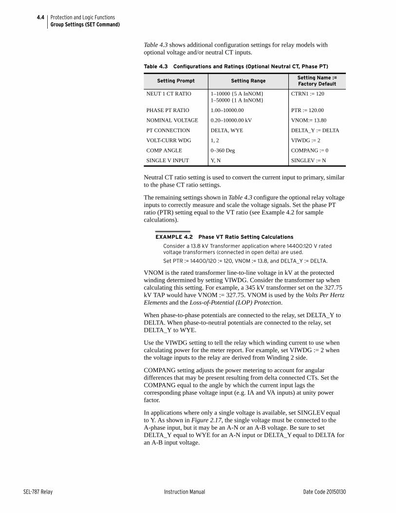
4.4
SEL-787 Relay Instruction Manual Date Code 20150130
Protection and Logic FunctionsGroup Settings (SET Command)
Table 4.3 shows additional configuration settings for relay models with optional voltage and/or neutral CT inputs.
Neutral CT ratio setting is used to convert the current input to primary, similar to the phase CT ratio settings.
The remaining settings shown in Table 4.3 configure the optional relay voltage inputs to correctly measure and scale the voltage signals. Set the phase PT ratio (PTR) setting equal to the VT ratio (see Example 4.2 for sample calculations).
EXAMPLE 4.2 Phase VT Ratio Setting Calculations
Consider a 13.8 kV Transformer application where 14400:120 V rated voltage transformers (connected in open delta) are used.
Set PTR := 14400/120 := 120, VNOM := 13.8, and DELTA_Y := DELTA.
VNOM is the rated transformer line-to-line voltage in kV at the protected winding determined by setting VIWDG. Consider the transformer tap when calculating this setting. For example, a 345 kV transformer set on the 327.75 kV TAP would have VNOM := 327.75. VNOM is used by the Volts Per Hertz Elements and the Loss-of-Potential (LOP) Protection.
When phase-to-phase potentials are connected to the relay, set DELTA_Y to DELTA. When phase-to-neutral potentials are connected to the relay, set DELTA_Y to WYE.
Use the VIWDG setting to tell the relay which winding current to use when calculating power for the meter report. For example, set VIWDG := 2 when the voltage inputs to the relay are derived from Winding 2 side.
COMPANG setting adjusts the power metering to account for angular differences that may be present resulting from delta connected CTs. Set the COMPANG equal to the angle by which the current input lags the corresponding phase voltage input (e.g. IA and VA inputs) at unity power factor.
In applications where only a single voltage is available, set SINGLEV equal to Y. As shown in Figure 2.17, the single voltage must be connected to the A-phase input, but it may be an A-N or an A-B voltage. Be sure to set DELTA_Y equal to WYE for an A-N input or DELTA_Y equal to DELTA for an A-B input voltage.
Table 4.3 Configurations and Ratings (Optional Neutral CT, Phase PT)
Setting Prompt Setting RangeSetting Name := Factory Default
NEUT 1 CT RATIO 1–10000 {5 A InNOM} 1–50000 {1 A InNOM}
CTRN1 := 120
PHASE PT RATIO 1.00–10000.00 PTR := 120.00
NOMINAL VOLTAGE 0.20–10000.00 kV VNOM:= 13.80
PT CONNECTION DELTA, WYE DELTA_Y := DELTA
VOLT-CURR WDG 1, 2 VIWDG := 2
COMP ANGLE 0–360 Deg COMPANG := 0
SINGLE V INPUT Y, N SINGLEV := N
4.5
Date Code 20150130 Instruction Manual SEL-787 Relay
Protection and Logic FunctionsBasic Protection
When you set SINGLEV equal to Y, the relay performance changes in the following ways:
➤ Power and Voltage Elements. When you use one voltage, the relay assumes that the system voltages are balanced in both magnitude and phase angle. Power, power factor, and positive-sequence impedance are calculated assuming balanced voltages.
➤ Metering. When you use one voltage, the relay displays magnitude and phase angle for the measured PT. The relay displays zero for the magnitudes of the unmeasured voltages. Balanced voltages are assumed for power, power factor, VG, and 3V2 metering.
Relays that are not equipped with phase voltage inputs hide these settings and disable voltage-based protection and metering functions.
VNOM Range CheckThe relay performs a range check for the VNOM setting that depends upon the voltage-input delta or wye configuration. Valid nominal voltage is 100–250 V secondary (l-l) when DELTA_Y is DELTA; it is 100–440 V when DELTA_Y is WYE.
Note that the VNOM setting is always in line-to-line primary kV, even when set for a wye configuration. You should be careful to use a solidly-grounded wye system for VNOM inputs greater than 250 V (l-l, secondary) to avoid a 1.73 increase in terminal voltages from a line-to-ground fault.
Basic ProtectionDifferential Element Protect your apparatus with dual-slope percentage differential protection.
Percentage differential protection provides more sensitive and secure protection than traditional differential protection; the dual-slope characteristic compensates for steady-state, proportional, and transient differential errors within the zone of protection. Steady-state errors are those that do not vary with loading through the differential zone. These include transformer magnetizing current and unmonitored loads. Proportional errors are those that vary with loading. These include relay measuring error, CT ratio errors, and errors because of tap changing. Transient errors are those that occur temporarily due to transients such as CT saturation.
The relay allows you to choose harmonic blocking, harmonic restraint, or both, providing stability during transformer inrush conditions. Even-numbered harmonics (second and fourth) provide security during energization, while fifth-harmonic blocking provides security for overexcitation conditions.
Operating CharacteristicThe SEL-787 has three differential elements (87R-1, 87R-2, and 87R-3). These elements employ Operate (IOP) and Restraint (IRT) quantities that the relay calculates from the winding input current. Figure 4.1 shows the relay characteristic. You can set the characteristic as either a single-slope, percentage differential characteristic or as a dual-slope, variable-percentage differential characteristic. Tripping occurs if the Operate quantity is greater than the curve value for the particular restraint quantity. A minimum pickup level for the Operate quantity must also be satisfied.
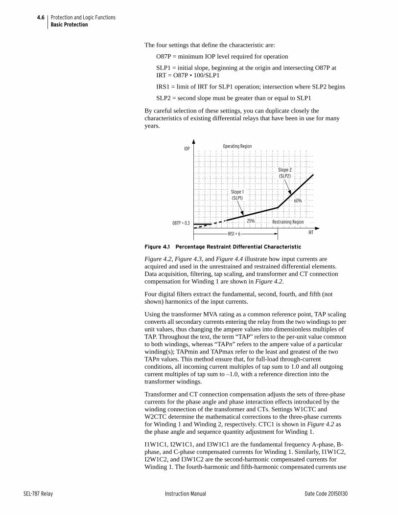
4.6
SEL-787 Relay Instruction Manual Date Code 20150130
Protection and Logic FunctionsBasic Protection
The four settings that define the characteristic are:
O87P = minimum IOP level required for operation
SLP1 = initial slope, beginning at the origin and intersecting O87P at IRT = O87P • 100/SLP1
IRS1 = limit of IRT for SLP1 operation; intersection where SLP2 begins
SLP2 = second slope must be greater than or equal to SLP1
By careful selection of these settings, you can duplicate closely the characteristics of existing differential relays that have been in use for many years.
Figure 4.1 Percentage Restraint Differential Characteristic
Figure 4.2, Figure 4.3, and Figure 4.4 illustrate how input currents are acquired and used in the unrestrained and restrained differential elements. Data acquisition, filtering, tap scaling, and transformer and CT connection compensation for Winding 1 are shown in Figure 4.2.
Four digital filters extract the fundamental, second, fourth, and fifth (not shown) harmonics of the input currents.
Using the transformer MVA rating as a common reference point, TAP scaling converts all secondary currents entering the relay from the two windings to per unit values, thus changing the ampere values into dimensionless multiples of TAP. Throughout the text, the term “TAP” refers to the per-unit value common to both windings, whereas “TAPn” refers to the ampere value of a particular winding(s); TAPmin and TAPmax refer to the least and greatest of the two TAPn values. This method ensure that, for full-load through-current conditions, all incoming current multiples of tap sum to 1.0 and all outgoing current multiples of tap sum to –1.0, with a reference direction into the transformer windings.
Transformer and CT connection compensation adjusts the sets of three-phase currents for the phase angle and phase interaction effects introduced by the winding connection of the transformer and CTs. Settings W1CTC and W2CTC determine the mathematical corrections to the three-phase currents for Winding 1 and Winding 2, respectively. CTC1 is shown in Figure 4.2 as the phase angle and sequence quantity adjustment for Winding 1.
I1W1C1, I2W1C1, and I3W1C1 are the fundamental frequency A-phase, B-phase, and C-phase compensated currents for Winding 1. Similarly, I1W1C2, I2W1C2, and I3W1C2 are the second-harmonic compensated currents for Winding 1. The fourth-harmonic and fifth-harmonic compensated currents use
Operating Region
Restraining Region
IRT
60%
25%
IOP
087P = 0.3
Slope 2(SLP2)
IRS1 = 6
Slope 1(SLP1)
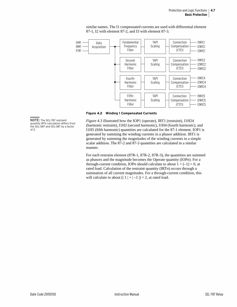
4.7
Date Code 20150130 Instruction Manual SEL-787 Relay
Protection and Logic FunctionsBasic Protection
similar names. The I1 compensated currents are used with differential element 87-1, I2 with element 87-2, and I3 with element 87-3.
Figure 4.2 Winding 1 Compensated Currents
NOTE: The SEL-787 restraint quantity IRTn calculation differs from the SEL-587 and SEL-387 by a factor of 2.
Figure 4.3 illustrated how the IOP1 (operate), IRT1 (restraint), I1H24 (harmonic restraint), I1H2 (second harmonic), I1H4 (fourth harmonic), and I1H5 (fifth harmonic) quantities are calculated for the 87-1 element. IOP1 is generated by summing the winding currents in a phasor addition. IRT1 is generated by summing the magnitudes of the winding currents in a simple scalar addition. The 87-2 and 87-3 quantities are calculated in a similar manner.
For each restraint element (87R-1, 87R-2, 87R-3), the quantities are summed as phasors and the magnitude becomes the Operate quantity (IOPn). For a through-current condition, IOPn should calculate to about 1 + (–1) = 0, at rated load. Calculation of the restraint quantity (IRTn) occurs through a summation of all current magnitudes. For a through-current condition, this will calculate to about (| 1 | + | –1 |) = 2, at rated load.
I1W1C1I2W1C1I3W1C1
I1W1C2I2W1C2I3W1C2
I1W1C4I2W1C4I3W1C4
IAW1IBW1ICW1
DataAcquisition
Fundamental Frequency
Filter
TAP1 Scaling
Connection Compensation
(CTC1)
Second- Harmonic
Filter
TAP1 Scaling
Connection Compensation
(CTC1)
Fourth- Harmonic
Filter
TAP1 Scaling
Connection Compensation
(CTC1)
I1W1C5I2W1C5I3W1C5
Fifth- Harmonic
Filter
TAP1 Scaling
Connection Compensation
(CTC1)
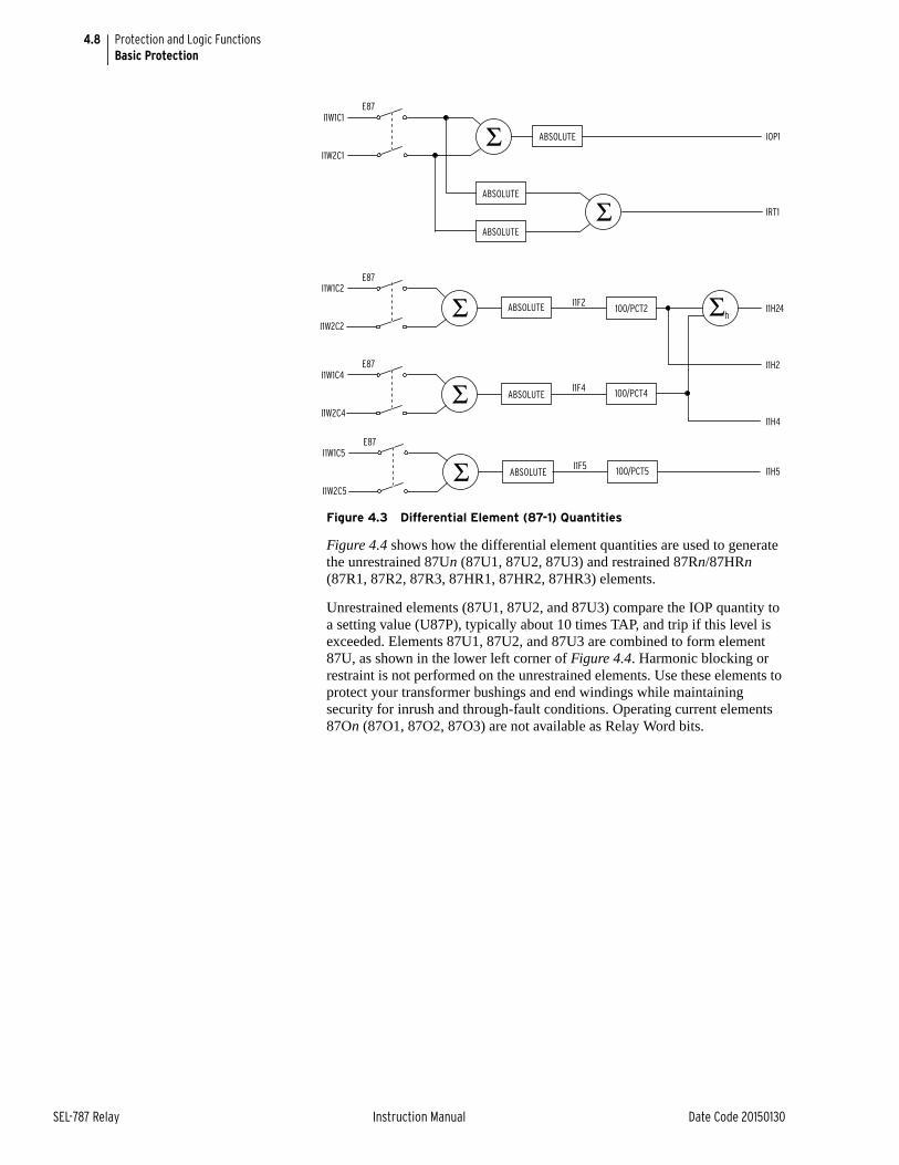
4.8
SEL-787 Relay Instruction Manual Date Code 20150130
Protection and Logic FunctionsBasic Protection
Figure 4.3 Differential Element (87-1) Quantities
Figure 4.4 shows how the differential element quantities are used to generate the unrestrained 87Un (87U1, 87U2, 87U3) and restrained 87Rn/87HRn (87R1, 87R2, 87R3, 87HR1, 87HR2, 87HR3) elements.
Unrestrained elements (87U1, 87U2, and 87U3) compare the IOP quantity to a setting value (U87P), typically about 10 times TAP, and trip if this level is exceeded. Elements 87U1, 87U2, and 87U3 are combined to form element 87U, as shown in the lower left corner of Figure 4.4. Harmonic blocking or restraint is not performed on the unrestrained elements. Use these elements to protect your transformer bushings and end windings while maintaining security for inrush and through-fault conditions. Operating current elements 87On (87O1, 87O2, 87O3) are not available as Relay Word bits.
IOP1
E87I1W1C1
I1W2C1Σ ABSOLUTE
I1W1C2
I1W2C2
I1W1C4
I1W2C4
IRT1
I1H24
I1H2
I1H4
Σh
ABSOLUTE
ABSOLUTE
100/PCT2
100/PCT4
E87
Σ ABSOLUTE
ABSOLUTE
E87
Σ I1F2
I1F4
Σ
I1W1C5
I1W2C5
100/PCT5
E87
Σ ABSOLUTEI1F5
I1H5

4.9
Date Code 20150130 Instruction Manual SEL-787 Relay
Protection and Logic FunctionsBasic Protection
Figure 4.4 Differential Element Decision Logic
Restrained elements (87R1, 87R2, and 87R3) determine whether the IOP quantity is greater than the restraint quantity using the differential characteristic shown in Figure 4.1. This characteristic is modified by increasing the restraint current threshold as a function of the second- and fourth-harmonic content in the input currents for the harmonic restraint elements (87HR1, 87HR2, and 87HR3). Set HRSTR = Y to activate the harmonic restraint element 87HR.
In element 87Rn, for example, the IOPn and IRTn quantities determine whether the relay trips. The logic enclosed within the dotted line of Figure 4.4 implements the Figure 4.1 characteristic. The differential element calculates a threshold as a function of IRTn. IOPn must exceed this threshold to assert 87Rn. The function uses the SLP1, SLP2, and IRS1 setting values, along with IRTn, to calculate the IOP value. The relay uses SLOPE2 in place of SLOPE1 when the Relay Word bit INRn is asserted. This features provides a high security mode of operation for 10 cycles when the transformer is energized. The differential element decision logic compares the calculated value, denoted f(IRTn), to the actual IOPn. If IOPn is greater, one input of the AND gate at the right receives a logic 1. Comparison of IOPn with the O87P setting determines the second AND input. If IOPn is greater than O87P, the bit 87On asserts. The AND gate condition is then satisfied, and Relay Word bit 87Rn asserts, indicating operation of the restrained differential element, n. This does not, as yet, produce a trip. The relay still needs the results of the harmonic blocking decision logic, which is described later.
Harmonic RestraintConsider the harmonic restraint feature (HRSTR = Y) if your practices require independent harmonic restraint. Blocking features are discussed in more detail later in this section.
For harmonic blocking, the harmonic content of the differential current must exceed the individual (PCT2 or PCT4) threshold values, i.e., the thresholds are treated as independent measurements of each harmonic value. For harmonic restraint, the values of the second- and fourth-harmonic currents are summed,
_+
_+
_+
_+
2 CYC
10 CYC
n = 1, 2, or 3
87U187U287U3
87U87HR187HR287HR3
87HB
IOPn
U87P (setting)
87Un
87Rn
87HRn
f(IRTn)
87R
Σc5HB1
87On
HRSTR = Y(setting)
87HR
IRTn
O87P (setting)
I1H24
RelayWordBits
INRn0.05
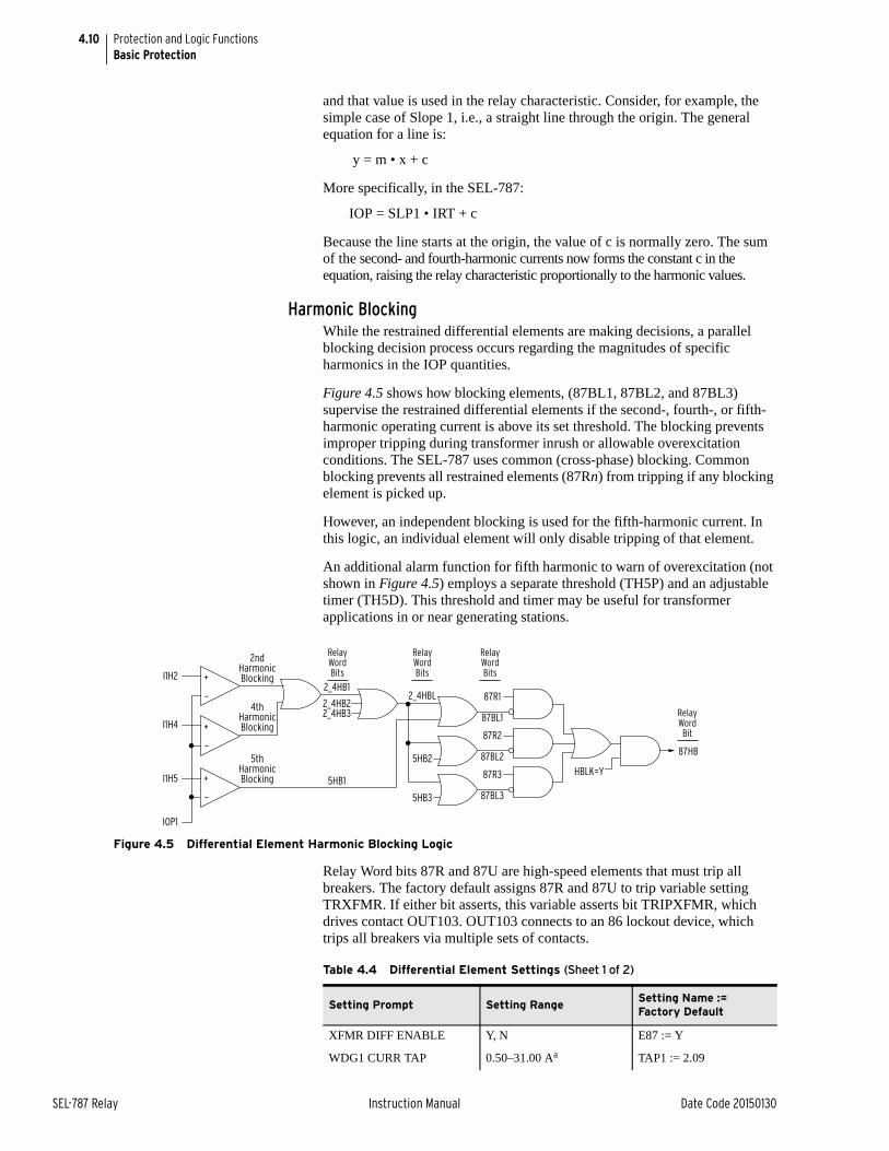
4.10
SEL-787 Relay Instruction Manual Date Code 20150130
Protection and Logic FunctionsBasic Protection
and that value is used in the relay characteristic. Consider, for example, the simple case of Slope 1, i.e., a straight line through the origin. The general equation for a line is:
y = m • x + c
More specifically, in the SEL-787:
IOP = SLP1 • IRT + c
Because the line starts at the origin, the value of c is normally zero. The sum of the second- and fourth-harmonic currents now forms the constant c in the equation, raising the relay characteristic proportionally to the harmonic values.
Harmonic BlockingWhile the restrained differential elements are making decisions, a parallel blocking decision process occurs regarding the magnitudes of specific harmonics in the IOP quantities.
Figure 4.5 shows how blocking elements, (87BL1, 87BL2, and 87BL3) supervise the restrained differential elements if the second-, fourth-, or fifth- harmonic operating current is above its set threshold. The blocking prevents improper tripping during transformer inrush or allowable overexcitation conditions. The SEL-787 uses common (cross-phase) blocking. Common blocking prevents all restrained elements (87Rn) from tripping if any blocking element is picked up.
However, an independent blocking is used for the fifth-harmonic current. In this logic, an individual element will only disable tripping of that element.
An additional alarm function for fifth harmonic to warn of overexcitation (not shown in Figure 4.5) employs a separate threshold (TH5P) and an adjustable timer (TH5D). This threshold and timer may be useful for transformer applications in or near generating stations.
Figure 4.5 Differential Element Harmonic Blocking Logic
Relay Word bits 87R and 87U are high-speed elements that must trip all breakers. The factory default assigns 87R and 87U to trip variable setting TRXFMR. If either bit asserts, this variable asserts bit TRIPXFMR, which drives contact OUT103. OUT103 connects to an 86 lockout device, which trips all breakers via multiple sets of contacts.
87HB
_+
_+
_+
5HB2
87R1
87BL1
87R2
87BL2
87R3
87BL3
2_4HBL2_4HB1
5HB3
2_4HB22_4HB3
5HB1
5thHarmonicBlocking
4thHarmonicBlocking
2ndHarmonicBlocking
HBLK=Y
I1H2
I1H4
I1H5
IOP1
RelayWordBits
RelayWordBits
RelayWordBits
RelayWordBit
Table 4.4 Differential Element Settings (Sheet 1 of 2)
Setting Prompt Setting RangeSetting Name := Factory Default
XFMR DIFF ENABLE Y, N E87 := Y
WDG1 CURR TAP 0.50–31.00 Aa TAP1 := 2.09
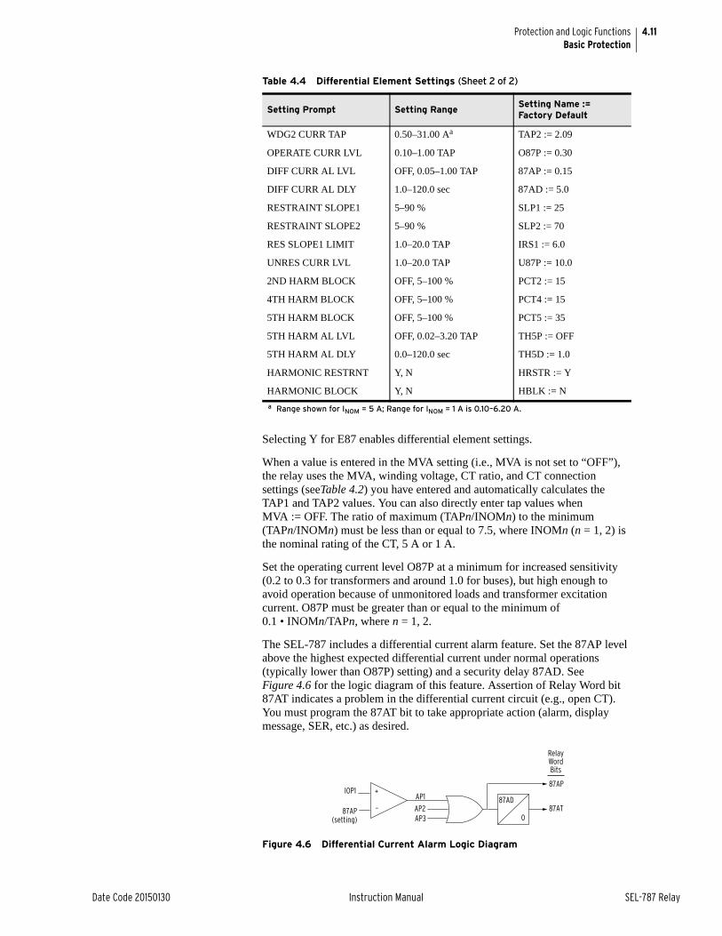
4.11
Date Code 20150130 Instruction Manual SEL-787 Relay
Protection and Logic FunctionsBasic Protection
Selecting Y for E87 enables differential element settings.
When a value is entered in the MVA setting (i.e., MVA is not set to “OFF”), the relay uses the MVA, winding voltage, CT ratio, and CT connection settings (seeTable 4.2) you have entered and automatically calculates the TAP1 and TAP2 values. You can also directly enter tap values when MVA := OFF. The ratio of maximum (TAPn/INOMn) to the minimum (TAPn/INOMn) must be less than or equal to 7.5, where INOMn (n = 1, 2) is the nominal rating of the CT, 5 A or 1 A.
Set the operating current level O87P at a minimum for increased sensitivity (0.2 to 0.3 for transformers and around 1.0 for buses), but high enough to avoid operation because of unmonitored loads and transformer excitation current. O87P must be greater than or equal to the minimum of 0.1 • INOMn/TAPn, where n = 1, 2.
The SEL-787 includes a differential current alarm feature. Set the 87AP level above the highest expected differential current under normal operations (typically lower than O87P) setting) and a security delay 87AD. See Figure 4.6 for the logic diagram of this feature. Assertion of Relay Word bit 87AT indicates a problem in the differential current circuit (e.g., open CT). You must program the 87AT bit to take appropriate action (alarm, display message, SER, etc.) as desired.
Figure 4.6 Differential Current Alarm Logic Diagram
WDG2 CURR TAP 0.50–31.00 Aa TAP2 := 2.09
OPERATE CURR LVL 0.10–1.00 TAP O87P := 0.30
DIFF CURR AL LVL OFF, 0.05–1.00 TAP 87AP := 0.15
DIFF CURR AL DLY 1.0–120.0 sec 87AD := 5.0
RESTRAINT SLOPE1 5–90 % SLP1 := 25
RESTRAINT SLOPE2 5–90 % SLP2 := 70
RES SLOPE1 LIMIT 1.0–20.0 TAP IRS1 := 6.0
UNRES CURR LVL 1.0–20.0 TAP U87P := 10.0
2ND HARM BLOCK OFF, 5–100 % PCT2 := 15
4TH HARM BLOCK OFF, 5–100 % PCT4 := 15
5TH HARM BLOCK OFF, 5–100 % PCT5 := 35
5TH HARM AL LVL OFF, 0.02–3.20 TAP TH5P := OFF
5TH HARM AL DLY 0.0–120.0 sec TH5D := 1.0
HARMONIC RESTRNT Y, N HRSTR := Y
HARMONIC BLOCK Y, N HBLK := N
a Range shown for INOM = 5 A; Range for INOM = 1 A is 0.10–6.20 A.
Table 4.4 Differential Element Settings (Sheet 2 of 2)
Setting Prompt Setting RangeSetting Name := Factory Default
87AP(setting)
87AD
0
IOP1
_
+
87AT
87AP
AP2AP3
AP1
RelayWordBits
4.12
SEL-787 Relay Instruction Manual Date Code 20150130
Protection and Logic FunctionsBasic Protection
Use the restraint slope percentage settings to discriminate between internal and external faults. Set SLP1 to accommodate current differences from steady-state and proportional errors such as power transformer tap-changer, CT errors, and relay error. Set SLP2 to accommodate transient error caused by CT saturation.
A two-slope, or variable-percentage differential application, improves sensitivity in the region where CT error is less and increases security in the high-current region where CT error is greater. We must define both slopes, as well as the Slope 1 limit or point IRS1, where SLP1 and SLP2 intersect. If you want a single slope characteristic, set both SLOPE1 and SLOPE2 to the desired slope value.
The purpose of the instantaneous unrestrained current element is to react quickly to very heavy current levels that clearly indicate an internal fault. Set the pickup level U87P to 8 to 10 times tap. The unrestrained differential element only responds to the fundamental frequency component of the differential operating current. It is unaffected by the SLP1, SLP2, IRS1, PCT2, or PCT5 settings. Thus, you must set the element pickup level high enough so as not to react to large inrush currents.
Energization of a transformer causes a temporary large flow of magnetizing inrush current into one terminal of a transformer, without the other terminal seeing this current. Thus, it appears as a differential current that could cause improper relay operation. Magnetizing inrush currents contain greater amounts of even-harmonic current than do fault currents. This even-harmonic current can be used to identify the inrush phenomenon and to prevent relay misoperation. The SEL-787 measures the amount of second-harmonic and fourth-harmonic currents flowing in the transformer. You can set the relay to block the percentage restrained differential element if the ratio of the second-harmonic and/or fourth-harmonic current to fundamental current (IF2/IF1, IF4/IF1) is greater than the PCT2 or PCT4 setting, respectively. Also, the differential element automatically goes into a high security mode for 10 cycles when the transformer is energized, see Figure 4.4 and the associated description.
According to industry standards (ANSI/IEEE C37.91, C37.102), overexcitation occurs when the ratio of the voltage to frequency (V/Hz) applied to the transformer terminals exceeds 1.05 per unit at full load or 1.1 per unit at no load. Transformer overexcitation produces odd-order harmonics (primarily fifth harmonic), which can appear as differential current to a transformer differential relay. The SEL-787 measures the amount of fifth-harmonic current flowing in the transformer. You can set the relay to block the percentage restrained differential element if the ratio of fifth-harmonic current to fundamental current (IF5/IF1) is greater than the PCT5 setting. Unit-generator step-up transformers at power plants are the primary users of fifth-harmonic blocking. Transformer voltage and generator frequency may vary somewhat during startup, overexciting the transformers.
Fifth-harmonic alarm level and delay settings (TH5P and TH5D) use the presence of fifth-harmonic differential current to assert a Relay Word bit TH5T. This bit indicates that the rated transformer excitation current is exceeded. You may consider triggering an alarm and/or event report if fifth-harmonic current exceeds the fifth-harmonic threshold that you set.
The SEL-787 includes common harmonic blocking (cross-phase blocking) and harmonic restraint logic; you can select either one or both of them. The combination of both logic functions provides optimum differential element operating speed and security. Use the HRSTR := Y setting to enable the
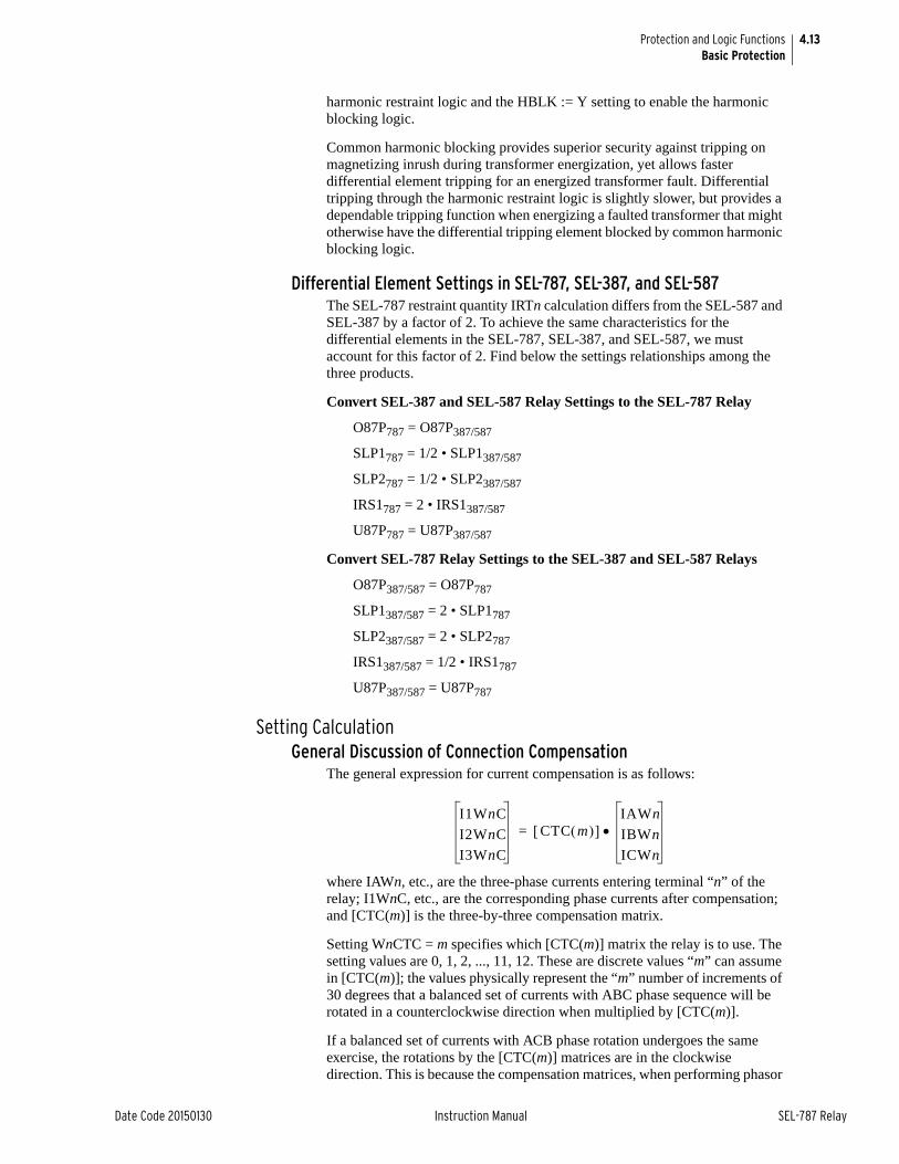
4.13
Date Code 20150130 Instruction Manual SEL-787 Relay
Protection and Logic FunctionsBasic Protection
harmonic restraint logic and the HBLK := Y setting to enable the harmonic blocking logic.
Common harmonic blocking provides superior security against tripping on magnetizing inrush during transformer energization, yet allows faster differential element tripping for an energized transformer fault. Differential tripping through the harmonic restraint logic is slightly slower, but provides a dependable tripping function when energizing a faulted transformer that might otherwise have the differential tripping element blocked by common harmonic blocking logic.
Differential Element Settings in SEL-787, SEL-387, and SEL-587The SEL-787 restraint quantity IRTn calculation differs from the SEL-587 and SEL-387 by a factor of 2. To achieve the same characteristics for the differential elements in the SEL-787, SEL-387, and SEL-587, we must account for this factor of 2. Find below the settings relationships among the three products.
Convert SEL-387 and SEL-587 Relay Settings to the SEL-787 Relay
O87P787 = O87P387/587
SLP1787 = 1/2 • SLP1387/587
SLP2787 = 1/2 • SLP2387/587
IRS1787 = 2 • IRS1387/587
U87P787 = U87P387/587
Convert SEL-787 Relay Settings to the SEL-387 and SEL-587 Relays
O87P387/587 = O87P787
SLP1387/587 = 2 • SLP1787
SLP2387/587 = 2 • SLP2787
IRS1387/587 = 1/2 • IRS1787
U87P387/587 = U87P787
Setting CalculationGeneral Discussion of Connection Compensation
The general expression for current compensation is as follows:
where IAWn, etc., are the three-phase currents entering terminal “n” of the relay; I1WnC, etc., are the corresponding phase currents after compensation; and [CTC(m)] is the three-by-three compensation matrix.
Setting WnCTC = m specifies which [CTC(m)] matrix the relay is to use. The setting values are 0, 1, 2, ..., 11, 12. These are discrete values “m” can assume in [CTC(m)]; the values physically represent the “m” number of increments of 30 degrees that a balanced set of currents with ABC phase sequence will be rotated in a counterclockwise direction when multiplied by [CTC(m)].
If a balanced set of currents with ACB phase rotation undergoes the same exercise, the rotations by the [CTC(m)] matrices are in the clockwise direction. This is because the compensation matrices, when performing phasor
I1WnC
I2WnC
I3WnC
CTC m IAWn
IBWn
ICWn
=
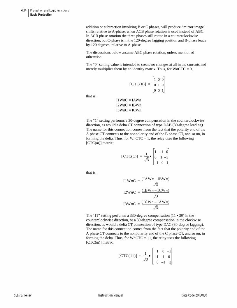
4.14
SEL-787 Relay Instruction Manual Date Code 20150130
Protection and Logic FunctionsBasic Protection
addition or subtraction involving B or C phases, will produce “mirror image” shifts relative to A-phase, when ACB phase rotation is used instead of ABC. In ACB phase rotation the three phases still rotate in a counterclockwise direction, but C-phase is in the 120-degree lagging position and B-phase leads by 120 degrees, relative to A-phase.
The discussions below assume ABC phase rotation, unless mentioned otherwise.
The “0” setting value is intended to create no changes at all in the currents and merely multiplies them by an identity matrix. Thus, for WnCTC = 0,
that is,
The “1” setting performs a 30-degree compensation in the counterclockwise direction, as would a delta CT connection of type DAB (30-degree leading). The name for this connection comes from the fact that the polarity end of the A phase CT connects to the nonpolarity end of the B phase CT, and so on, in forming the delta. Thus, for WnCTC = 1, the relay uses the following [CTC(m)] matrix:
that is,
The ‘11” setting performs a 330-degree compensation (11 • 30) in the counterclockwise direction, or a 30-degree compensation in the clockwise direction, as would a delta CT connection of type DAC (30-degree lagging). The name for this connection comes from the fact that the polarity end of the A phase CT connects to the nonpolarity end of the C phase CT, and so on, in forming the delta. Thus, for WnCTC = 11, the relay uses the following [CTC(m)] matrix:
I1WnC = IAWnI2WnC = IBWnI3WnC = ICWn
CTC 0 1 0 0
0 1 0
0 0 1
=
CTC 1 1
3-------
1 –1 0
0 1 –1
1 0 1–
=
I1WnC IAWn IBWn– 3
------------------------------------------=
I2WnC IBWn ICWn– 3
------------------------------------------=
I3WnC ICWn IAWn– 3
------------------------------------------=
CTC 11 1
3-------
1 0 –1
–1 1 0
0 –1 1
=
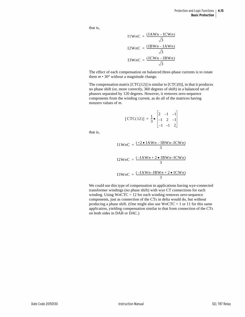
4.15
Date Code 20150130 Instruction Manual SEL-787 Relay
Protection and Logic FunctionsBasic Protection
that is,
The effect of each compensation on balanced three-phase currents is to rotate them m • 30° without a magnitude change.
The compensation matrix [CTC(12)] is similar to [CTC(0)], in that it produces no phase shift (or, more correctly, 360 degrees of shift) in a balanced set of phasors separated by 120 degrees. However, it removes zero-sequence components from the winding current, as do all of the matrices having nonzero values of m.
that is,
We could use this type of compensation in applications having wye-connected transformer windings (no phase shift) with wye CT connections for each winding. Using WnCTC = 12 for each winding removes zero-sequence components, just as connection of the CTs in delta would do, but without producing a phase shift. (One might also use WnCTC = 1 or 11 for this same application, yielding compensation similar to that from connection of the CTs on both sides in DAB or DAC.)
I1WnC IAWn ICWn– 3
------------------------------------------=
I2WnC IBWn IAWn– 3
------------------------------------------=
I3WnC ICWn IBWn– 3
------------------------------------------=
CTC 12 13---
2 –1 –1
–1 2 –1
–1 –1 2
=
I1WnC +2 IAWn IBWn ICWn–– 3
--------------------------------------------------------------------------=
I2WnC –IAWn 2 IBWn ICWn–+ 3
--------------------------------------------------------------------------=
I3WnC –IAWn I– BWn 2 ICWn+ 3
--------------------------------------------------------------------------=
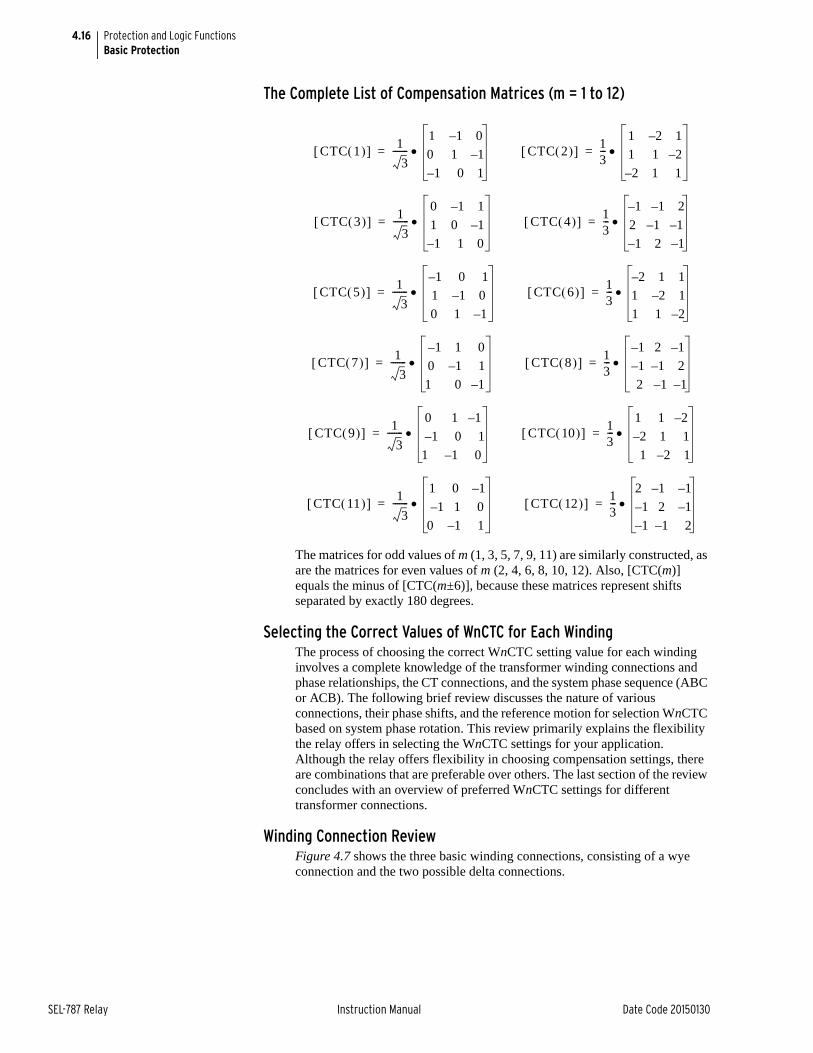
4.16
SEL-787 Relay Instruction Manual Date Code 20150130
Protection and Logic FunctionsBasic Protection
The Complete List of Compensation Matrices (m = 1 to 12)
The matrices for odd values of m (1, 3, 5, 7, 9, 11) are similarly constructed, as are the matrices for even values of m (2, 4, 6, 8, 10, 12). Also, [CTC(m)] equals the minus of [CTC(m±6)], because these matrices represent shifts separated by exactly 180 degrees.
Selecting the Correct Values of WnCTC for Each WindingThe process of choosing the correct WnCTC setting value for each winding involves a complete knowledge of the transformer winding connections and phase relationships, the CT connections, and the system phase sequence (ABC or ACB). The following brief review discusses the nature of various connections, their phase shifts, and the reference motion for selection WnCTC based on system phase rotation. This review primarily explains the flexibility the relay offers in selecting the WnCTC settings for your application. Although the relay offers flexibility in choosing compensation settings, there are combinations that are preferable over others. The last section of the review concludes with an overview of preferred WnCTC settings for different transformer connections.
Winding Connection ReviewFigure 4.7 shows the three basic winding connections, consisting of a wye connection and the two possible delta connections.
CTC 1 1
3-------
1 –1 0
0 1 –1
–1 0 1
= CTC 2 13---
1 –2 1
1 1 –2
–2 1 1
=
CTC 3 1
3-------
0 –1 1
1 0 –1
–1 1 0
= CTC 4 13---
–1 –1 2
2 –1 –1
–1 2 –1
=
CTC 5 1
3-------
–1 0 1
1 –1 0
0 1 –1
= CTC 6 13---
–2 1 1
1 –2 1
1 1 –2
=
CTC 7 1
3-------
–1 1 0
0 –1 1
1 0 –1
= CTC 8 13---
–1 2 –1
–1 –1 2
2 –1 –1
=
CTC 9 1
3-------
0 1 –1
–1 0 1
1 –1 0
= CTC 10 13---
1 1 –2
–2 1 1
1 –2 1
=
CTC 11 1
3-------
1 0 –1
–1 1 0
0 –1 1
= CTC 12 13---
2 –1 –1
–1 2 –1
–1 –1 2
=

4.17
Date Code 20150130 Instruction Manual SEL-787 Relay
Protection and Logic FunctionsBasic Protection
Figure 4.7 Winding Connections, Phase Shifts, and Compensation Direction
The wye connection consists of connecting one end of each winding to a common or neutral point, leaving the other ends of each winding for the line terminals. Because the windings do not interconnect at the line ends, the line current equals the respective winding current, A, B, or C, and no phase shift occurs in the line currents with respect to the winding currents. The neutral point, if it is grounded, permits flow of zero-sequence current components in the windings and line outputs.
There are two possible delta connections. In determining WnCTC, it is essential to know not only that the CTs or transformer windings are connected in delta but in which delta. In this manual we call these delta connections DAB and DAC. In the DAB connection the polarity end of the A winding connects to the nonpolarity end of the B winding, and so on, to produce the delta. In the DAC connection the polarity end of the A winding connects to the nonpolarity end of the C winding, and so on, to produce the delta. In Figure 4.7, an arrowhead indicates the polarity end of each winding.
These arrangements involve a connection point between two windings at each line terminal; the line currents are not the same as the winding currents, but are in fact the phasor difference between the associated winding currents. Therefore, the line currents will shift in phase by some amount with respect to the winding currents. In the DAB connection the line currents from the A, B, and C line terminals are, respectively, A-B, B-C, and C-A in terms of the winding currents. In the DAC connection the line currents from the A, B, and C line terminals are, respectively, A-C, B-A, and C-B in terms of the winding currents. The phase shift produced by each physical type of delta depends on the system phase sequence.
A
Connection Line Outputs Connection Phase Shift
ABC Rotation ACB Rotation
WYE
DAB
DAC
(Xfmr. or CT)
A, B, C
A—B, B—C, C—A
A—C, B—A, C—B
A
C B
C
B
0°
30° CCW
30° CW
0°
30° CW
30° CCW
A
C
B
A
B
C
B
C
A
B C
WnCTC(CCW)
WnCTC(CW)
A
WnCTCDirection
4.18
SEL-787 Relay Instruction Manual Date Code 20150130
Protection and Logic FunctionsBasic Protection
NOTE: The terms “lead” and “lag” refer to the assumed counterclockwise (CCW) rotation of the phasors for both ABC and ACB phase rotation. “Lead” implies movement in the CCW direction; “lag” is movement in the clockwise (CW) direction.
In the ABC phase sequence B lags A by 120 degrees and C leads A by 120 degrees. The DAB connection line current at terminal A is A-B, which in this case is a phasor that leads A winding current by 30 degrees. For this reason, DAB is often referred to as the “leading connection.” However, DAB is the leading connection only for ABC phase sequence. In the ACB phase sequence C lags A by 120 degrees, and B leads A by 120 degrees. Terminal A line current is still A-B, but current now lags A winding current by 30 degrees.
The DAC connection produces opposite shifts to DAB. In the ABC phase sequence line current from terminal A is A-C, which lags A winding current by 30 degrees. In the ACB phase sequence line current A is still A-C, but this result leads A winding current by 30 degrees.
Five-Step Compensation ProcessThe process of determining WnCTC for each winding involves the following five basic steps. Two examples illustrate important points about the five steps. For an additional resource, see the “Winding Compensation Settings Worksheet” (SEL_WCTC_R1_0.xls, available on the SEL-787 Product Literature CD).
Step 1. Establish the phase direction for the terminal-A line voltage for each three-phase winding of the transformer. (This step requires transformer nameplate drawings and/or internal connection diagrams.)
Step 2. Adjust the terminal-A line voltage direction for each set of input currents by the phase shift (if any) of the current transformer connection. (Reference Figure 4.7 for this step.)
Step 3. Select any one of the adjusted terminal-A directions from Step 2, to serve as the reference direction. (The relay compensates all other windings to line up with this reference.)
Step 4. Choose a setting for WnCTC for each set of winding input currents. This setting is the number of 30-degree increments needed to adjust each nonreference winding to line it up with the reference. This number will range from 0 to 12 increments.
For ABC phase sequence, begin at the winding direction and proceed in a CCW direction until reaching the reference. For ACB phase sequence, begin at the winding direction and proceed in a CW direction until reaching the reference. Figure 4.7 shows these compensation directions.
Step 5. If any winding needs no phase correction (zero degrees), but is a grounded-wye winding having wye-connected CTs, choose WnCTC = 12 for that winding, rather than WnCTC = 0. This setting will remove zero-sequence current components from the relay currents to prevent false differential tripping on external ground faults. (All non-zero values of WnCTC remove zero-sequence current.)
Example 1 for WnCTC SelectionFigure 4.8 illustrates the first example. This is a two-winding transformer with a DAB delta primary and secondary connected in grounded wye. The secondary winding has DAB delta-connected CTs. We assume ABC phase rotation. Using the “hour of the clock” convention for specifying transformer connections, the transformer is a “Dy1” connection. This means the transformer has a high-voltage delta whose reference is “noon” and a wye
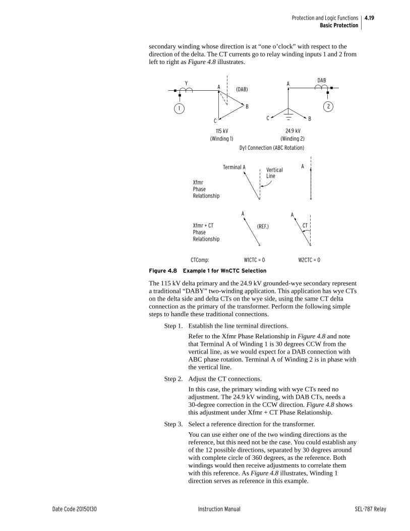
4.19
Date Code 20150130 Instruction Manual SEL-787 Relay
Protection and Logic FunctionsBasic Protection
secondary winding whose direction is at “one o’clock” with respect to the direction of the delta. The CT currents go to relay winding inputs 1 and 2 from left to right as Figure 4.8 illustrates.
Figure 4.8 Example 1 for WnCTC Selection
The 115 kV delta primary and the 24.9 kV grounded-wye secondary represent a traditional “DABY” two-winding application. This application has wye CTs on the delta side and delta CTs on the wye side, using the same CT delta connection as the primary of the transformer. Perform the following simple steps to handle these traditional connections.
Step 1. Establish the line terminal directions.
Refer to the Xfmr Phase Relationship in Figure 4.8 and note that Terminal A of Winding 1 is 30 degrees CCW from the vertical line, as we would expect for a DAB connection with ABC phase rotation. Terminal A of Winding 2 is in phase with the vertical line.
Step 2. Adjust the CT connections.
In this case, the primary winding with wye CTs need no adjustment. The 24.9 kV winding, with DAB CTs, needs a 30-degree correction in the CCW direction. Figure 4.8 shows this adjustment under Xfmr + CT Phase Relationship.
Step 3. Select a reference direction for the transformer.
You can use either one of the two winding directions as the reference, but this need not be the case. You could establish any of the 12 possible directions, separated by 30 degrees around with complete circle of 360 degrees, as the reference. Both windings would then receive adjustments to correlate them with this reference. As Figure 4.8 illustrates, Winding 1 direction serves as reference in this example.
XfmrPhaseRelationship
Xfmr + CTPhaseRelationship
CTComp: W1CTC = 0 W2CTC = 0
Terminal A VerticalLine
A
AA
(REF.) CT
Dy1 Connection (ABC Rotation)
115 kV 24.9 kV
A (DAB)
C
B
Y
1 2
A
BC
DAB
(Winding 2)(Winding 1)
4.20
SEL-787 Relay Instruction Manual Date Code 20150130
Protection and Logic FunctionsBasic Protection
Step 4. Choose the WnCTC settings for the windings.
Because Winding 1 is the reference, we need no adjustment; the setting is W1CTC = 0. Note that the adjusted Winding 2 inputs coincide exactly with the reference direction; we need make no adjustment for the 24.9 kV winding either. Therefore, the setting is W2CTC = 0. As mentioned earlier, these two windings represent a classical DABY application. We can see this from the fact that the WnCTC setting is zero for both windings. The CT connections themselves perform exactly the right correction without additional help from the relay. The process is nearly complete.
Step 5. As a final step, ensure that no wye-connected winding having wye-connected CTs is set at WnCTC = 0 (uncompensated).
Were this the case, zero-sequence currents could appear in these relay inputs but in no others, and a possible false trip could occur for external ground faults. Any non-zero value of WnCTC will eliminate the zero-sequence. In this example there is no wye-connected winding with wye-connected CTs. The selection is complete. The relay receives the settings as W1CTC = 0 and W2CTC = 0 (alternately, you can set ICOM ;= N because no compensation is required from the relay).
Example 2 for WnCTC SelectionFigure 4.9 illustrates the second example. This is another two-winding transformer, for which we have chosen rather unusual winding phase relationships in order to show the flexibility of the winding compensation feature in the SEL-787.
The transformer has a 115 kV primary winding that is wye connected, with wye-connected CTs. The 34.5 kV secondary winding is DAB connected, but designated with the A line terminal at the “7 o’clock” position with respect to the primary A line terminal. It has wye-connected CTs. This transformer is therefore a “Yd7” connection type. We assume ABC phase rotation. The CT currents go to relay winding inputs 1 and 2 from left to right as Figure 4.9 shows.
Step 1. Establish the line terminal directions.
Figure 4.9 shows these phase directions under Xfmr Phase Relationship. Based on the transformer designation, the terminal direction are shown at “noon” and “7 o’clock.”
Step 2. Adjust the transformer winding directions based on the CT connections. Neither windings need correction, because they both have wye-connected CTs.
Step 3. Select a reference direction. In this example we have chosen the delta secondary winding as reference.
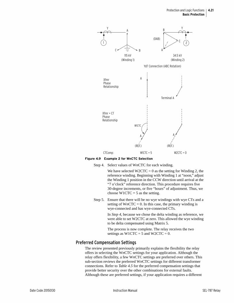
4.21
Date Code 20150130 Instruction Manual SEL-787 Relay
Protection and Logic FunctionsBasic Protection
Figure 4.9 Example 2 for WnCTC Selection
Step 4. Select values of WnCTC for each winding.
We have selected W2CTC = 0 as the setting for Winding 2, the reference winding. Beginning with Winding 1 at “noon,” adjust the Winding 1 position in the CCW direction until arrival at the “7 o’clock” reference direction. This procedure requires five 30-degree increments, or five “hours” of adjustment. Thus, we choose W1CTC = 5 as the setting.
Step 5. Ensure that there will be no wye windings with wye CTs and a setting of WnCTC = 0. In this case, the primary winding is wye-connected and has wye-connected CTs.
In Step 4, because we chose the delta winding as reference, we were able to set W2CTC at zero. This allowed the wye winding to be delta compensated using Matrix 5.
The process is now complete. The relay receives the two settings as W1CTC = 5 and W2CTC = 0.
Preferred Compensation SettingsThe review presented previously primarily explains the flexibility the relay offers in selecting the WnCTC settings for your application. Although the relay offers flexibility, a few WnCTC settings are preferred over others. This sub-section reviews the preferred WnCTC settings for different transformer connections. Refer to Table 4.5 for the preferred compensation settings that provide better security over the other combinations for external faults. Although these are preferred settings, if your application requires a different
Y
1
115 kV
A
BC
34.5 kV
2
B
C
A
Y
(DAB)
Yd7 Connection (ABC Rotation)
A
A
XfmrPhaseRelationship
Xfmr + CTPhaseRelationship
CTComp: W1CTC = 5 W2CTC = 0
Terminal A
A
(REF.) (REF.)
W1CTC
(Winding 2)(Winding 1)
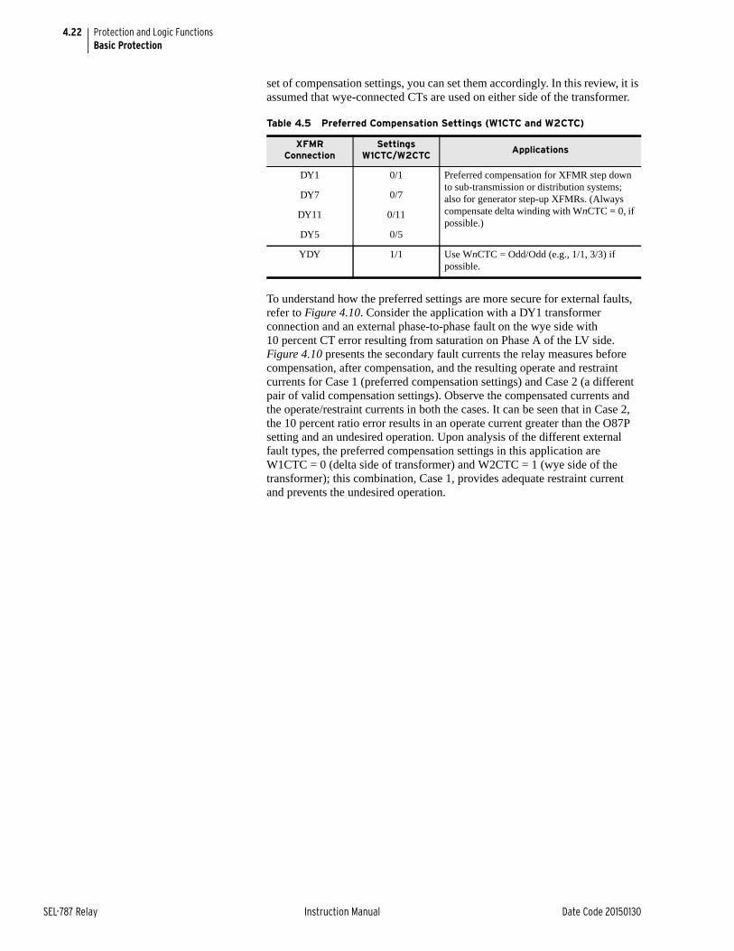
4.22
SEL-787 Relay Instruction Manual Date Code 20150130
Protection and Logic FunctionsBasic Protection
set of compensation settings, you can set them accordingly. In this review, it is assumed that wye-connected CTs are used on either side of the transformer.
To understand how the preferred settings are more secure for external faults, refer to Figure 4.10. Consider the application with a DY1 transformer connection and an external phase-to-phase fault on the wye side with 10 percent CT error resulting from saturation on Phase A of the LV side. Figure 4.10 presents the secondary fault currents the relay measures before compensation, after compensation, and the resulting operate and restraint currents for Case 1 (preferred compensation settings) and Case 2 (a different pair of valid compensation settings). Observe the compensated currents and the operate/restraint currents in both the cases. It can be seen that in Case 2, the 10 percent ratio error results in an operate current greater than the O87P setting and an undesired operation. Upon analysis of the different external fault types, the preferred compensation settings in this application are W1CTC = 0 (delta side of transformer) and W2CTC = 1 (wye side of the transformer); this combination, Case 1, provides adequate restraint current and prevents the undesired operation.
Table 4.5 Preferred Compensation Settings (W1CTC and W2CTC)
XFMR Connection
Settings W1CTC/W2CTC
Applications
DY1 0/1 Preferred compensation for XFMR step down to sub-transmission or distribution systems; also for generator step-up XFMRs. (Always compensate delta winding with WnCTC = 0, if possible.)
DY7 0/7
DY11 0/11
DY5 0/5
YDY 1/1 Use WnCTC = Odd/Odd (e.g., 1/1, 3/3) if possible.
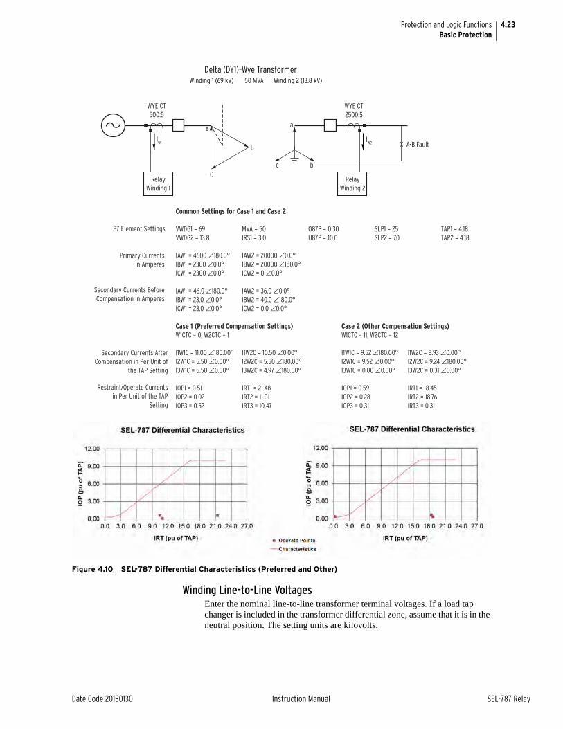
4.23
Date Code 20150130 Instruction Manual SEL-787 Relay
Protection and Logic FunctionsBasic Protection
Figure 4.10 SEL-787 Differential Characteristics (Preferred and Other)
Winding Line-to-Line VoltagesEnter the nominal line-to-line transformer terminal voltages. If a load tap changer is included in the transformer differential zone, assume that it is in the neutral position. The setting units are kilovolts.
Relay Winding 1
Relay Winding 2
WYE CT500:5
IW1
A
B
C
a
bc
Winding 1 (69 kV) Winding 2 (13.8 kV)
Delta (DY1)–Wye Transformer
WYE CT2500:5
X A-B Fault
Common Settings for Case 1 and Case 2
VWDG1 = 69 MVA = 50 O87P = 0.30 SLP1 = 25 TAP1 = 4.18VWDG2 = 13.8 IRS1 = 3.0 U87P = 10.0 SLP2 = 70 TAP2 = 4.18
IAW1 = 4600 ∠180.0° IAW2 = 20000 ∠0.0°IBW1 = 2300 ∠0.0° IBW2 = 20000 ∠180.0°ICW1 = 2300 ∠0.0° ICW2 = 0 ∠0.0°
IAW1 = 46.0 ∠180.0° IAW2 = 36.0 ∠0.0°IBW1 = 23.0 ∠0.0° IBW2 = 40.0 ∠180.0°ICW1 = 23.0 ∠0.0° ICW2 = 0.0 ∠0.0°
Case 1 (Preferred Compensation Settings) Case 2 (Other Compensation Settings)W1CTC = 0, W2CTC = 1 W1CTC = 11, W2CTC = 12
I1W1C = 11.00 ∠180.00° I1W2C = 10.50 ∠0.00° I1W1C = 9.52 ∠180.00° I1W2C = 8.93 ∠0.00°I2W1C = 5.50 ∠0.00° I2W2C = 5.50 ∠180.00° I2W1C = 9.52 ∠0.00° I2W2C = 9.24 ∠180.00°I3W1C = 5.50 ∠0.00° I3W2C = 4.97 ∠180.00° I3W1C = 0.00 ∠0.00° I3W2C = 0.31 ∠0.00°
IOP1 = 0.51 IRT1 = 21.48 IOP1 = 0.59 IRT1 = 18.45IOP2 = 0.02 IRT2 = 11.01 IOP2 = 0.28 IRT2 = 18.76IOP3 = 0.52 IRT3 = 10.47 IOP3 = 0.31 IRT3 = 0.31
Secondary Currents Before Compensation in Amperes
Secondary Currents AfterCompensation in Per Unit of
the TAP Setting
Restraint/Operate Currents in Per Unit of the TAP
Setting
Primary Currentsin Amperes
50 MVA
IW2
87 Element Settings
4.24
SEL-787 Relay Instruction Manual Date Code 20150130
Protection and Logic FunctionsBasic Protection
Current TAPThe relay uses a standard equation to set TAPn, based on settings entered for the particular winding (n denotes the winding number.)
where:
The relay calculates TAPn with the following limitations:
➤ The tap settings are within the range 0.1 • INOMn and 6.2 • INOMn
➤ The ratio of the highest (TAPn/INOMn) to the lowest (TAPn/INOMn) is less than or equal to 7.5, where n = 1, 2
Restrained Element Operating Current PickupThe O87P setting range is 0.1 to 1.0; we suggest an O87P setting of 0.2 to 0.3. The setting must be at a minimum for increased sensitivity but high enough to avoid operation because of steady-state errors such as unmonitored station service loads, transformer excitation current, and relay measuring error at very low current levels. The setting must also yield an operating current greater than or equal to a minimum of 0.1 • INOMn/TAPn, where n = 1, 2.
Restraint Slope PercentageThe purpose of the percentage restraint characteristic is to allow the relay to differentiate between differential current from an internal fault versus differential current during normal or external fault conditions. You must select slope characteristic settings that balance security and dependability. To do this, it is helpful to determine what slope ratio is characteristic of normal conditions (slope must exceed that for security) and what slope ratio is characteristic of an internal fault (the slope must be below that for dependability). In the case of the SEL-787 Relay, the slope ratio for a bolted internal fault is 100%.
The sources of differential current for external faults fall into three categories:
➤ Differential current that is not proportional to the current flow through the zone (steady state).
➤ Differential current that is proportional to current flow through the zone (proportional).
➤ Differential current that is transient in nature (transient).
SLP1 should be set above normal steady-state and proportional errors. SLP2 is used to accommodate transient errors. The following is a list of typical sources of error that must be considered.
➤ Excitation current (typically 1 to 4%)
➤ CT accuracy (typically less than 3% in the nominal range)
➤ No-Load Tap Changer (NLTC) (typically ±5%)
C = 1 if WnCT setting = Y (wye-connected CTs)C = if WnCT setting = D (delta-connected CTs)
MVA = maximum power transformer capacity setting (must be the same for all TAPn calculations)
VWDGn = winding line-to-line voltage setting, in kVCTRn = current transformer ratio setting
TAPnMVA 1000
3 VWDG CTRn------------------------------------------------------ C=
3

4.25
Date Code 20150130 Instruction Manual SEL-787 Relay
Protection and Logic FunctionsBasic Protection
➤ Load Tap-Changer (LTC) (typically ±10%)
➤ Relay accuracy (±5% or ±0.02 • INOM, whichever is largest.)
We recognize that the excitation current of the transformer is not proportional to load flow. However, a conservative approach would include it as a proportional error.
CTs create both steady-state and transient errors, which can result in false differential current. IEEE Standard Requirements for Instrument Transformers, IEEE Standard C57.13-1993 specifies that a relay-accuracy CT must be 3 percent accurate at rated current and 10 percent accurate at 20 times rated current when ZB is the standard burden. It is important to note that the rated current specified in the standard is a symmetrical sinusoidal waveform (it does not have a transient DC component). Because the burden is usually designed to be much smaller than the standard burden, the error current will likely be much less than 3 percent for current flow at low multiples of the nominal rating of the CTs.
The errors can be added to determine the amount of error that the SLP1 characteristic must accommodate for normal system conditions. At that point, use the following equation and add margin to determine SLP1 and determine the minimum limit of the allowable slope ratio.
where:
The variable restraint characteristic provided by SLP2 at high multiples of TAP for a through fault accommodates transient CT error. SLP2 can be set fairly high without jeopardizing sensitivity for low-grade partial winding faults. The CTs should be evaluated for the likelihood of going into saturation for a through fault, and SLP2 should be adjusted accordingly. Another consideration for selecting the SLP2 setting is that the effectiveness of the variable percentage depends on SLP1 and IRS1, which determine the starting point of SLP2. If SLP1 is set very low, a higher SLP2 may be warranted.
Unrestrained Element Current PickupThe instantaneous unrestrained current element is intended to react quickly to very heavy current levels that clearly indicate an internal fault. Set the pickup level (U87P) to approximately 8 to 10 times TAP. The unrestrained differential element only responds to the fundamental frequency component of the differential operating current. It is not affected by the SLP1, SLP2, IRS1, PCT2, or PCT5 settings. Thus, it must be set high enough so as not to react to large inrush currents.
Note that the U87P must be set lower than the minimum of 31 • INOMn/TAPn, where n = 1, 2.
Second-Harmonic BlockingTransformer simulations show that magnetizing inrush current usually yields more than 30 percent of IF2/IF1 in the first cycle of the inrush. A setting of 15 percent usually provides a margin for security. However, some types of transformers, or the presence within the differential zone of equipment that
SLP1MIN = slope ratio that will just accommodate Err with no marginErr = amount of error expected in normal operation
k = AVERAGE restraint scaling factor (1 for the SEL-787)
SLP1MIN%Err%
200 Err%– k------------------------------------------ 100=

4.26
SEL-787 Relay Instruction Manual Date Code 20150130
Protection and Logic FunctionsBasic Protection
draws a fundamental current of its own, may require setting the threshold as low as 7 percent. For example, the additional fundamental frequency charging current of a long cable run on the transformer secondary terminals could “dilute” the level of second harmonic seen at the primary to less than 15 percent.
Fourth-Harmonic BlockingTransformer magnetizing inrush currents are generated during transformer energization when the current contains a dc offset due to point-on-wave switching. Inrush conditions typically are detected using even harmonics and are used to prevent misoperations due to inrush. The largest even-harmonic current component is usually second harmonic followed by fourth harmonic. Use fourth-harmonic blocking to provide additional security against inrush conditions; set PCT4 less than PCT2.
Fifth-Harmonic BlockingFourier analysis of transformer currents during overexcitation indicates that a 35 percent fifth-harmonic setting is adequate to block the percentage differential element. To disable fifth-harmonic blocking, set PCT5 to OFF.
You may use the presence of fifth-harmonic differential current to assert an alarm output during startup. This alarm indicates that the rated transformer excitation current is exceeded. At full load, a TH5P setting of 0.1 corresponds to 10 percent of the fundamental current. A delay, TH5D, that you can set prevents the relay from indicating transient presence of fifth-harmonic currents.
You may consider triggering an event report if transformer excitation current exceeds the fifth-harmonic threshold.
There are two criteria for setting TH5P:
TH5P minimum (0.05 •INOMn/TAPn)
where:
n = 1, 2 and INOMn is nominal current of corresponding CT
Example of Setting the SEL-787 Relay The example represents a typical transformer application and demonstrates the use of CT compensation settings and tap calculations.
Figure 2.19 illustrates the application. The transformer is a 138 kV to 13.8 kV. The transformer has a maximum rating of 30 MVA. Both windings have wye-connected current transformers, with ratios of 200/5 A at 138 kV, and 2000/5 A at 13.8 kV. We have connected the transformer per IEEE standards, with the low voltage delta lagging the high-voltage wye by 30 degrees.
Step 1. Enable the differential settings as follows:
E87 := Y
Step 2. Select settings for the current transformer connection and ratio for each winding.
All CTs connect in wye. The ratios are equal to primary current divided by secondary current. The settings are as follows:
Step 3. Set the transformer maximum rating.
138 kV 13.8 kV
W1CT = WYE W2CT = WYECTR1 = 40 CTR2 = 400
4.27
Date Code 20150130 Instruction Manual SEL-787 Relay
Protection and Logic FunctionsBasic Protection
We use this rating for all windings in the later tap calculation:
MVA = 30
Step 4. Decide whether to use internal CT compensation and determine compensation settings.
Because there are both wye and delta transformer windings but only wye CTs, we must adjust for the phase angle shift. In the “traditional” differential relay connection the wye transformer windings would have their CTs connected in delta to produce a shift in the same direction as that produced in the transformer. In this case a “DAC” or “30-degree lagging” connection would have been used. This would not only shift the currents, but it would remove the zero-sequence current component by physically subtracting the appropriate phase currents via the delta connection. We achieve the same effect within the relay by using the selected compensation. The settings are:
The relay will multiply the wye CT currents from the wye transformer windings by the matrix [CTC(11)] to give the same results as the physical DAC CT connection.
Step 5. Enter winding line-to-line voltages.
The relay needs these voltages for the tap calculation. Voltages are in units of kV. For this example we enter the following values:
The relay now calculates each tap current, using the formula stated previously:
Thus, we have the following:
The relay calculates these taps automatically if MVA is given. If MVA is set to OFF, you must calculate the taps and enter them individually.
The relay will check to see if a violation of the maximum tap ratio has occurred, and will notify you of the violation.
Step 6. Set the differential element characteristic. Select the settings according to our suggestions in the earlier setting descriptions.
ICOM = Y (choose to define the CT compensation)W1CTC = 11 W2CTC = 0
VWDG1 = 138 VWDG2 = 13.8
TAPnMVA 1000
3 VWDGn CTRn--------------------------------------------------------- C=
where
C 1 for wye CTs=
TAP1 30MVA 10003 138kV 40
-----------------------------------------=
TAP1 3.14=
TAP2 30MVA 10003 13.8kV 400
----------------------------------------------=
TAP2 3.14=
4.28
SEL-787 Relay Instruction Manual Date Code 20150130
Protection and Logic FunctionsBasic Protection
For this example, we have selected a two slope, variable-percentage differential characteristic for maximum sensitivity at low currents and greater tolerance for CT saturation on external high-current faults.
The minimum error for selecting SLP1 for this application is determined as follows:
➢ Excitation current (4%)
➢ CT accuracy (3%)
➢ No-Load Tap Changer (NLTC) (5%)
➢ Load Tap-Changer (LTC) (0%)
➢ Relay accuracy (±5% or ±0.02 • INOM, whichever is largest) (5%)
The CTs have been evaluated for maximum through fault and found to be unlikely to saturate severely. So, SLP2 does not have to be set higher than normal.
The settings are as follows:
Remember that the O87P setting must yield an operating current value of at least a minimum of 0.1 • INOMn/TAPn, where n = 1, 2. In this case, O87P = minimum ((0.1 • INOMn)/TAPn) = 0.5/3.14 = 0.159. Therefore, the O87P setting of 0.3 is valid.
The differential unit settings are complete for this specific application. At this point you can also choose to set backup overcurrent elements which we discuss at the end of this section.
Application GuidelinesIt is vital that you select adequate current transformers for a transformer differential application. Use the following procedure, based on ANSI/IEEE Standard C37.110: 1996, IEEE Guide for the Application of Current Transformers Used for Protective Relaying Purposes.
O87P = 0.3 (Operate current pickup in multiple of tap)
SLP1 = 15 (15 percent initial slope)SLP2 = 50 (50 percent second slope)IRS1 = 6.0 (limit of Slope 1, Restraint current in
multiple of tap)U87P = 10 (unrestrained differential Operate current
level, multiple of tap)PCT4 = 15 (block operation if fourth harmonic is
above 15 percent)PCT5 = 35 (block operation if fifth harmonic is
above 35 percent)TH5P = OFF (no fifth-harmonic alarm)
HRSTR = Y (harmonic restraint enabled)HBLK = Y (harmonic blocking enabled)
SLP1MIN%17
200 17– ------------------------- 100 9.3%= =
4.29
Date Code 20150130 Instruction Manual SEL-787 Relay
Protection and Logic FunctionsBasic Protection
CT ArrangementsUse separate relay restraint circuits for each power source to the relay. In the SEL-787 you may apply two restraint inputs to the relay. You may connect CT secondary windings in parallel only if both circuits meet the following criteria:
➤ They are connected at the same voltage level.
➤ Both have CTs that are matched in ratio and C voltage ratings.
➤ Both circuits are radial (no fault current contributions).
CT SizingSizing a CT to avoid saturation for the maximum asymmetrical fault current is ideal but not always possible. Such sizing requires CTs with C voltage ratings greater than (1 + X/R) times the burden voltage for the maximum symmetrical fault current, where X/R is the reactance-to-resistance ratio of the primary system.
As a rule of thumb, CT performance will be satisfactory if the CT secondary maximum symmetrical external fault current multiplied by the total secondary burden in ohms is less than half of the C voltage rating of the CT. The following CT selection procedure uses this second guideline.
CT Ratio Selection
Step 1. Determine the secondary side burdens in ohms for all current transformers connected to the relay.
Step 2. Select the CT ratio, considering the maximum continuous secondary current, IHS, based on the highest MVA rating of the transformer.
For wye-connected CTs, the relay current, IREL, equals IHS. For delta-connected CTs, IREL equals 3 • IHS. Select the nearest standard ratio such that IREL is between 0.1 • INOM and 1.0 • INOM A secondary, where INOM is the relay nominal secondary current, 1 A or 5 A.
Step 3. Select the remaining CT ratios (e.g., CTR2) by considering the maximum continuous secondary current, ILS.
As before, for wye-connected CTs IREL equals ILS. For delta-connected CTs IREL equals 3 • ILS. Select the nearest standard ratio such that IREL is between 0.1 • INOM and 1.0 • INOM A secondary.
The SEL-787 calculates settings TAP1 and TAP2 if the ratio of maximum (TAPn/INOMn) to minimum (TAPn/INOMn) is less than or equal to 7.5. When the relay calculates the tap settings, it reduces CT mismatch to less than 1 percent. Allowable tap settings are in the range (0.1-6.2) • INOM.
If the ratio of maximum (TAPn/INOMn) to minimum (TAPn/INOMn) is greater than 7.5, select a different CT ratio to meet the previous conditions. You can often do this by selecting a higher CT ratio for the smallest rated winding, but you may need to apply auxiliary CTs to achieve the required ratio. In this case, repeat Step 2 and Step 3.
Step 4. Calculate the maximum symmetrical fault current for an external fault, and verify that the CT secondary currents do not exceed your utility standard maximum allowed CT current, typically 20 • INOM. If necessary, reselect the CT ratios and repeat Step 2 through Step 4.
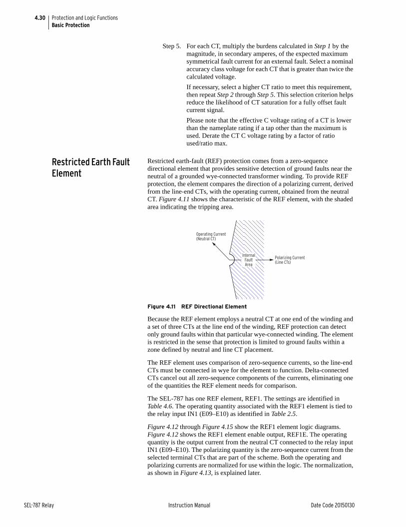
4.30
SEL-787 Relay Instruction Manual Date Code 20150130
Protection and Logic FunctionsBasic Protection
Step 5. For each CT, multiply the burdens calculated in Step 1 by the magnitude, in secondary amperes, of the expected maximum symmetrical fault current for an external fault. Select a nominal accuracy class voltage for each CT that is greater than twice the calculated voltage.
If necessary, select a higher CT ratio to meet this requirement, then repeat Step 2 through Step 5. This selection criterion helps reduce the likelihood of CT saturation for a fully offset fault current signal.
Please note that the effective C voltage rating of a CT is lower than the nameplate rating if a tap other than the maximum is used. Derate the CT C voltage rating by a factor of ratio used/ratio max.
Restricted Earth Fault Element
Restricted earth-fault (REF) protection comes from a zero-sequence directional element that provides sensitive detection of ground faults near the neutral of a grounded wye-connected transformer winding. To provide REF protection, the element compares the direction of a polarizing current, derived from the line-end CTs, with the operating current, obtained from the neutral CT. Figure 4.11 shows the characteristic of the REF element, with the shaded area indicating the tripping area.
Figure 4.11 REF Directional Element
Because the REF element employs a neutral CT at one end of the winding and a set of three CTs at the line end of the winding, REF protection can detect only ground faults within that particular wye-connected winding. The element is restricted in the sense that protection is limited to ground faults within a zone defined by neutral and line CT placement.
The REF element uses comparison of zero-sequence currents, so the line-end CTs must be connected in wye for the element to function. Delta-connected CTs cancel out all zero-sequence components of the currents, eliminating one of the quantities the REF element needs for comparison.
The SEL-787 has one REF element, REF1. The settings are identified in Table 4.6. The operating quantity associated with the REF1 element is tied to the relay input IN1 (E09–E10) as identified in Table 2.5.
Figure 4.12 through Figure 4.15 show the REF1 element logic diagrams. Figure 4.12 shows the REF1 element enable output, REF1E. The operating quantity is the output current from the neutral CT connected to the relay input IN1 (E09–E10). The polarizing quantity is the zero-sequence current from the selected terminal CTs that are part of the scheme. Both the operating and polarizing currents are normalized for use within the logic. The normalization, as shown in Figure 4.13, is explained later.
Polarizing Current (Line CTs)
Operating Current (Neutral CT)
InternalFault Area
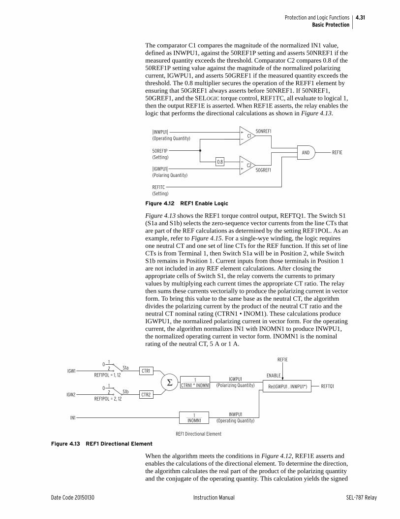
4.31
Date Code 20150130 Instruction Manual SEL-787 Relay
Protection and Logic FunctionsBasic Protection
The comparator C1 compares the magnitude of the normalized IN1 value, defined as INWPU1, against the 50REF1P setting and asserts 50NREF1 if the measured quantity exceeds the threshold. Comparator C2 compares 0.8 of the 50REF1P setting value against the magnitude of the normalized polarizing current, IGWPU1, and asserts 50GREF1 if the measured quantity exceeds the threshold. The 0.8 multiplier secures the operation of the REFF1 element by ensuring that 50GREF1 always asserts before 50NREF1. If 50NREF1, 50GREF1, and the SELOGIC torque control, REF1TC, all evaluate to logical 1, then the output REF1E is asserted. When REF1E asserts, the relay enables the logic that performs the directional calculations as shown in Figure 4.13.
Figure 4.12 REF1 Enable Logic
Figure 4.13 shows the REF1 torque control output, REFTQ1. The Switch S1 (S1a and S1b) selects the zero-sequence vector currents from the line CTs that are part of the REF calculations as determined by the setting REF1POL. As an example, refer to Figure 4.15. For a single-wye winding, the logic requires one neutral CT and one set of line CTs for the REF function. If this set of line CTs is from Terminal 1, then Switch S1a will be in Position 2, while Switch S1b remains in Position 1. Current inputs from those terminals in Position 1 are not included in any REF element calculations. After closing the appropriate cells of Switch S1, the relay converts the currents to primary values by multiplying each current times the appropriate CT ratio. The relay then sums these currents vectorially to produce the polarizing current in vector form. To bring this value to the same base as the neutral CT, the algorithm divides the polarizing current by the product of the neutral CT ratio and the neutral CT nominal rating (CTRN1 • INOM1). These calculations produce IGWPU1, the normalized polarizing current in vector form. For the operating current, the algorithm normalizes IN1 with INOMN1 to produce INWPU1, the normalized operating current in vector form. INOMN1 is the nominal rating of the neutral CT, 5 A or 1 A.
Figure 4.13 REF1 Directional Element
When the algorithm meets the conditions in Figure 4.12, REF1E asserts and enables the calculations of the directional element. To determine the direction, the algorithm calculates the real part of the product of the polarizing quantity and the conjugate of the operating quantity. This calculation yields the signed
|INWPU1|(Operating Quantity)
50REF1P(Setting)
|IGWPU1|(Polaring Quantity)
REF1TC(Setting)
0.8
C1
C250GREF1
50NREF1
AND REF1E
IGW1
IGW2
IN1
1CTRN1 * INOMN1
IGWPU1(Polarizing Quantity)
1INOMN1
INWPU1(Operating Quantity)
Re(IGWPU1 . INWPU1*)
ENABLE
REF1E
REFTQ1
REF1 Directional Element
ΣCTR1
CTR2
S1a
S1b
12
0
12
0
REF1POL = 1, 12
REF1POL = 2, 12
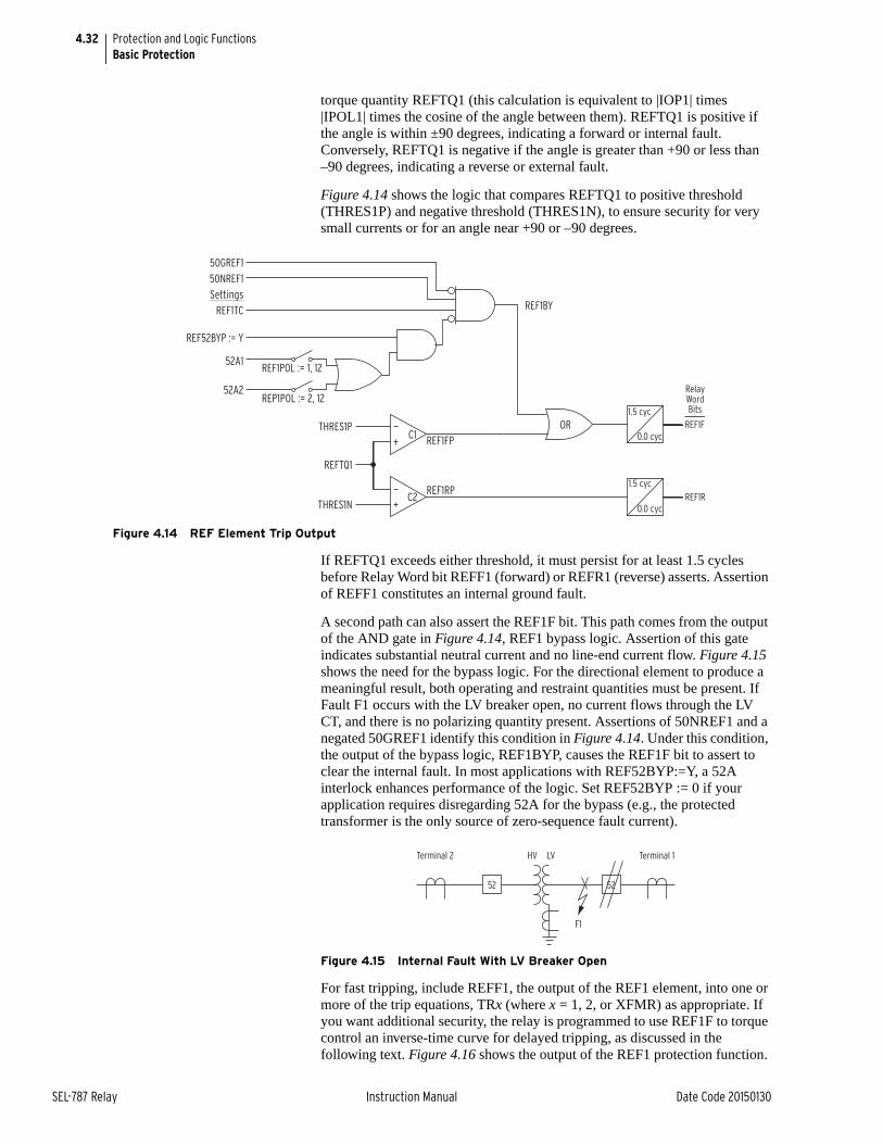
4.32
SEL-787 Relay Instruction Manual Date Code 20150130
Protection and Logic FunctionsBasic Protection
torque quantity REFTQ1 (this calculation is equivalent to |IOP1| times |IPOL1| times the cosine of the angle between them). REFTQ1 is positive if the angle is within ±90 degrees, indicating a forward or internal fault. Conversely, REFTQ1 is negative if the angle is greater than +90 or less than –90 degrees, indicating a reverse or external fault.
Figure 4.14 shows the logic that compares REFTQ1 to positive threshold (THRES1P) and negative threshold (THRES1N), to ensure security for very small currents or for an angle near +90 or –90 degrees.
Figure 4.14 REF Element Trip Output
If REFTQ1 exceeds either threshold, it must persist for at least 1.5 cycles before Relay Word bit REFF1 (forward) or REFR1 (reverse) asserts. Assertion of REFF1 constitutes an internal ground fault.
A second path can also assert the REF1F bit. This path comes from the output of the AND gate in Figure 4.14, REF1 bypass logic. Assertion of this gate indicates substantial neutral current and no line-end current flow. Figure 4.15 shows the need for the bypass logic. For the directional element to produce a meaningful result, both operating and restraint quantities must be present. If Fault F1 occurs with the LV breaker open, no current flows through the LV CT, and there is no polarizing quantity present. Assertions of 50NREF1 and a negated 50GREF1 identify this condition in Figure 4.14. Under this condition, the output of the bypass logic, REF1BYP, causes the REF1F bit to assert to clear the internal fault. In most applications with REF52BYP:=Y, a 52A interlock enhances performance of the logic. Set REF52BYP := 0 if your application requires disregarding 52A for the bypass (e.g., the protected transformer is the only source of zero-sequence fault current).
Figure 4.15 Internal Fault With LV Breaker Open
For fast tripping, include REFF1, the output of the REF1 element, into one or more of the trip equations, TRx (where x = 1, 2, or XFMR) as appropriate. If you want additional security, the relay is programmed to use REF1F to torque control an inverse-time curve for delayed tripping, as discussed in the following text. Figure 4.16 shows the output of the REF1 protection function.
THRES1P
REFTQ1
THRES1N
1.5 cyc
0.0 cyc
1.5 cyc
0.0 cycC1
C2
REF1BY
ORREF1FP
REF1RP
REF1F
REF1R
RelayWordBits
50GREF150NREF1Settings
REF1TC
REF52BYP := Y
52A1
52A2
REF1POL := 1, 12
REP1POL := 2, 12
52 52
F1
Terminal 2 HV LV Terminal 1
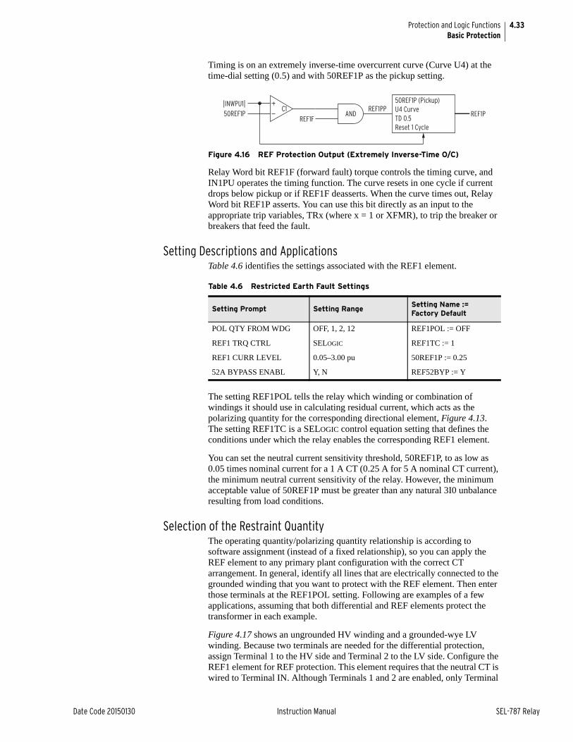
4.33
Date Code 20150130 Instruction Manual SEL-787 Relay
Protection and Logic FunctionsBasic Protection
Timing is on an extremely inverse-time overcurrent curve (Curve U4) at the time-dial setting (0.5) and with 50REF1P as the pickup setting.
Figure 4.16 REF Protection Output (Extremely Inverse-Time O/C)
Relay Word bit REF1F (forward fault) torque controls the timing curve, and IN1PU operates the timing function. The curve resets in one cycle if current drops below pickup or if REF1F deasserts. When the curve times out, Relay Word bit REF1P asserts. You can use this bit directly as an input to the appropriate trip variables, TRx (where x = 1 or XFMR), to trip the breaker or breakers that feed the fault.
Setting Descriptions and ApplicationsTable 4.6 identifies the settings associated with the REF1 element.
The setting REF1POL tells the relay which winding or combination of windings it should use in calculating residual current, which acts as the polarizing quantity for the corresponding directional element, Figure 4.13. The setting REF1TC is a SELOGIC control equation setting that defines the conditions under which the relay enables the corresponding REF1 element.
You can set the neutral current sensitivity threshold, 50REF1P, to as low as 0.05 times nominal current for a 1 A CT (0.25 A for 5 A nominal CT current), the minimum neutral current sensitivity of the relay. However, the minimum acceptable value of 50REF1P must be greater than any natural 3I0 unbalance resulting from load conditions.
Selection of the Restraint QuantityThe operating quantity/polarizing quantity relationship is according to software assignment (instead of a fixed relationship), so you can apply the REF element to any primary plant configuration with the correct CT arrangement. In general, identify all lines that are electrically connected to the grounded winding that you want to protect with the REF element. Then enter those terminals at the REF1POL setting. Following are examples of a few applications, assuming that both differential and REF elements protect the transformer in each example.
Figure 4.17 shows an ungrounded HV winding and a grounded-wye LV winding. Because two terminals are needed for the differential protection, assign Terminal 1 to the HV side and Terminal 2 to the LV side. Configure the REF1 element for REF protection. This element requires that the neutral CT is wired to Terminal IN. Although Terminals 1 and 2 are enabled, only Terminal
|INWPU1|50REF1P
C1REF1F
ANDREF1PP
50REF1P (Pickup)U4 CurveTD 0.5Reset 1 Cycle
REF1P
Table 4.6 Restricted Earth Fault Settings
Setting Prompt Setting RangeSetting Name := Factory Default
POL QTY FROM WDG OFF, 1, 2, 12 REF1POL := OFF
REF1 TRQ CTRL SELOGIC REF1TC := 1
REF1 CURR LEVEL 0.05–3.00 pu 50REF1P := 0.25
52A BYPASS ENABL Y, N REF52BYP := Y
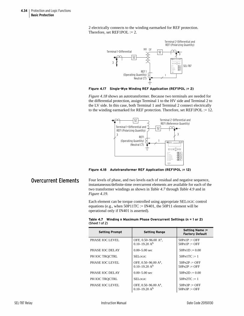
4.34
SEL-787 Relay Instruction Manual Date Code 20150130
Protection and Logic FunctionsBasic Protection
2 electrically connects to the winding earmarked for REF protection. Therefore, set REF1POL := 2.
Figure 4.17 Single-Wye Winding REF Application (REF1POL := 2)
Figure 4.18 shows an autotransformer. Because two terminals are needed for the differential protection, assign Terminal 1 to the HV side and Terminal 2 to the LV side. In this case, both Terminal 1 and Terminal 2 connect electrically to the winding earmarked for REF protection. Therefore, set REF1POL := 12.
Figure 4.18 Autotransformer REF Application (REF1POL := 12)
Overcurrent Elements Four levels of phase, and two levels each of residual and negative sequence, instantaneous/definite-time overcurrent elements are available for each of the two transformer windings as shown in Table 4.7 through Table 4.9 and in Figure 4.19.
Each element can be torque controlled using appropriate SELOGIC control equations (e.g., when 50P11TC := IN401, the 50P11 element will be operational only if IN401 is asserted).
Terminal 2–Differential andREF1 (Polarizing Quantity)
3
REF 1(Operating Quantity)
Neutral CT)1
HV LV
52
52
3SEL-787
Terminal 1–Differential
3
Terminal 2—Differential andREF1 (Reference Quantity)
3
1
52
52
REF1(Operating Quantity)
(Neutral CT)
Terminal 1—Differential andREF1 (Polarizing Quantity)
Table 4.7 Winding n Maximum Phase Overcurrent Settings (n = 1 or 2) (Sheet 1 of 2)
Setting Prompt Setting Range Setting Name := Factory Default
PHASE IOC LEVEL OFF, 0.50–96.00 Aa, 0.10–19.20 Ab
50Pn1P := OFF50Pn1P := OFF
PHASE IOC DELAY 0.00–5.00 sec 50Pn1D := 0.00
PH IOC TRQCTRL SELOGIC 50Pn1TC := 1
PHASE IOC LEVEL OFF, 0.50–96.00 Aa, 0.10–19.20 Ab
50Pn2P := OFF50Pn2P := OFF
PHASE IOC DELAY 0.00–5.00 sec 50Pn2D := 0.00
PH IOC TRQCTRL SELOGIC 50Pn2TC := 1
PHASE IOC LEVEL OFF, 0.50–96.00 Aa, 0.10–19.20 Ab
50Pn3P := OFF50Pn3P := OFF

4.35
Date Code 20150130 Instruction Manual SEL-787 Relay
Protection and Logic FunctionsBasic Protection
NOTE: The cosine filter provides excellent performance in removing dc offset and harmonics. However, the bipolar peak detector has the best performance in situations of severe CT saturation when the cosine filter magnitude estimation is significantly degraded. Combining the two methods provides an elegant solution for ensuring dependable short circuit overcurrent element operation.
The phase instantaneous overcurrent elements (50Pn1 through 50Pn4; see Figure 4.19) normally operate using the output of the one cycle cosine filtered phase current. During severe CT saturation, the cosine filtered phase current magnitude may be substantially reduced because of the distorted secondary waveform. If the overcurrent element relied only on the output of the cosine filtered secondary current, this may severely delay and may even jeopardize the operation of any high-set instantaneous overcurrent element. For any phase instantaneous overcurrent element in the SEL-787 relay set above eight times the relay current input rating (40 A in a 5 A relay), the overcurrent element also operates on the output of a bipolar peak detector if the current waveform is highly distorted, as is the case with severe CT saturation. This ensures fast operation of the 50P phase overcurrent elements even with severe CT saturation.
PHASE IOC DELAY 0.00–5.00 sec 50Pn3D := 0.00
PH IOC TRQCTRL SELOGIC 50Pn3TC := 1
PHASE IOC LEVEL OFF, 0.50–96.00 Aa, 0.10–19.20 Ab
50Pn4P := OFF50Pn4P := OFF
PHASE IOC DELAY 0.00–5.00 sec 50Pn4D := 0.00
PH IOC TRQCTRL SELOGIC 50Pn4TC := 1
a For INOM = 5 A.b For INOM = 1 A.
Table 4.7 Winding n Maximum Phase Overcurrent Settings (n = 1 or 2) (Sheet 2 of 2)
Setting Prompt Setting Range Setting Name := Factory Default
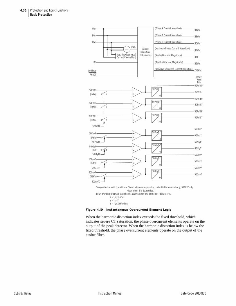
4.36
SEL-787 Relay Instruction Manual Date Code 20150130
Protection and Logic FunctionsBasic Protection
Figure 4.19 Instantaneous Overcurrent Element Logic
When the harmonic distortion index exceeds the fixed threshold, which indicates severe CT saturation, the phase overcurrent elements operate on the output of the peak detector. When the harmonic distortion index is below the fixed threshold, the phase overcurrent elements operate on the output of the cosine filter.
50Pn1P
|IAWn|
IAWn
IBWn
ICWn
IN1
PHROT
IGWn|IPWn|
|IN1|
|IGWn|
50Pn1AP
CurrentMagnitude
Calculations
50Pn1BP
|ICWn|
50Pn1CP
50Pn1TC
50PnxP50PnxT
50N1yP50N1yT
Settings
(Maximum Phase Current Magnitude)
(Neutral Current Magnitude)
(Residual Current Magnitude)
50N1yD
0
50PnxD
0
Negative-Sequence Current Calculation
(Negative-Sequence Current Magnitude) |3I2Wn|
50GnyP50GnyT
50QnyP50QnyT
50QnyD
0
50GnyD
0
|IAWn|
|IBWn|
(Phase A Current Magnitude)
(Phase B Current Magnitude)
(Phase C Current Magnitude) |ICWn|
50Pn1CT
|IBWn|
50QnyP
50GnyP
50N1yP
50PnxP
|3I2Wn|
50QnyTC
|IGWn|
50GnyTC
|IN1|
50N1yTC
|IPWn|
50PnxTC
RelayWordBits
50Pn1BT
50Pn1AT
50Pn1P
50Pn1P
50Pn1D
0
50Pn1D
0
50Pn1D
0
Torque Control switch position = Closed when corresponding control bit is asserted (e.g., 50P11TC = 1), Open when it is deasserted.Relay Word bit ORED50T (not shown) asserts when any of the 50_T bit asserts. x = 1, 2, 3, or 4 y = 1 or 2 n = 1 or 2 (Winding)
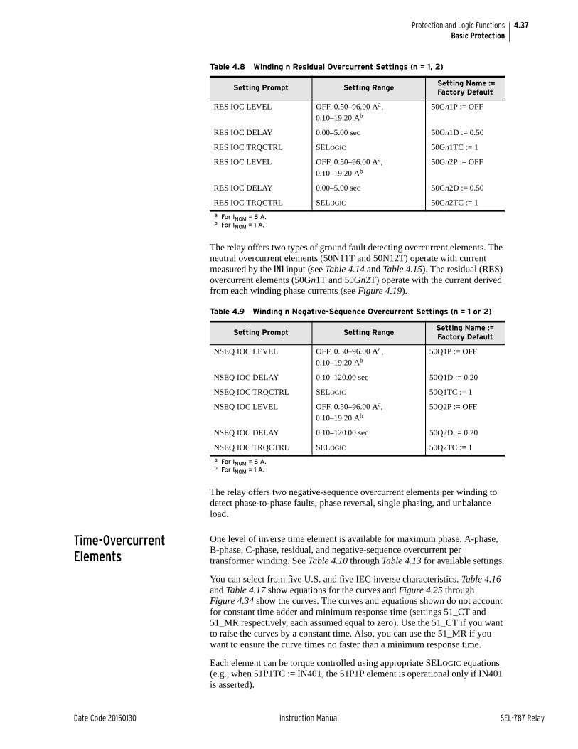
4.37
Date Code 20150130 Instruction Manual SEL-787 Relay
Protection and Logic FunctionsBasic Protection
The relay offers two types of ground fault detecting overcurrent elements. The neutral overcurrent elements (50N11T and 50N12T) operate with current measured by the IN1 input (see Table 4.14 and Table 4.15). The residual (RES) overcurrent elements (50Gn1T and 50Gn2T) operate with the current derived from each winding phase currents (see Figure 4.19).
.
The relay offers two negative-sequence overcurrent elements per winding to detect phase-to-phase faults, phase reversal, single phasing, and unbalance load.
Time-Overcurrent Elements
One level of inverse time element is available for maximum phase, A-phase, B-phase, C-phase, residual, and negative-sequence overcurrent per transformer winding. See Table 4.10 through Table 4.13 for available settings.
You can select from five U.S. and five IEC inverse characteristics. Table 4.16 and Table 4.17 show equations for the curves and Figure 4.25 through Figure 4.34 show the curves. The curves and equations shown do not account for constant time adder and minimum response time (settings 51_CT and 51_MR respectively, each assumed equal to zero). Use the 51_CT if you want to raise the curves by a constant time. Also, you can use the 51_MR if you want to ensure the curve times no faster than a minimum response time.
Each element can be torque controlled using appropriate SELOGIC equations (e.g., when 51P1TC := IN401, the 51P1P element is operational only if IN401 is asserted).
Table 4.8 Winding n Residual Overcurrent Settings (n = 1, 2)
Setting Prompt Setting Range Setting Name := Factory Default
RES IOC LEVEL OFF, 0.50–96.00 Aa,
0.10–19.20 Ab
a For INOM = 5 A.b For INOM = 1 A.
50Gn1P := OFF
RES IOC DELAY 0.00–5.00 sec 50Gn1D := 0.50
RES IOC TRQCTRL SELOGIC 50Gn1TC := 1
RES IOC LEVEL OFF, 0.50–96.00 Aa,
0.10–19.20 Ab 50Gn2P := OFF
RES IOC DELAY 0.00–5.00 sec 50Gn2D := 0.50
RES IOC TRQCTRL SELOGIC 50Gn2TC := 1
Table 4.9 Winding n Negative-Sequence Overcurrent Settings (n = 1 or 2)
Setting Prompt Setting RangeSetting Name := Factory Default
NSEQ IOC LEVEL OFF, 0.50–96.00 Aa,
0.10–19.20 Ab
a For INOM = 5 A.b For INOM = 1 A.
50Q1P := OFF
NSEQ IOC DELAY 0.10–120.00 sec 50Q1D := 0.20
NSEQ IOC TRQCTRL SELOGIC 50Q1TC := 1
NSEQ IOC LEVEL OFF, 0.50–96.00 Aa,
0.10–19.20 Ab50Q2P := OFF
NSEQ IOC DELAY 0.10–120.00 sec 50Q2D := 0.20
NSEQ IOC TRQCTRL SELOGIC 50Q2TC := 1
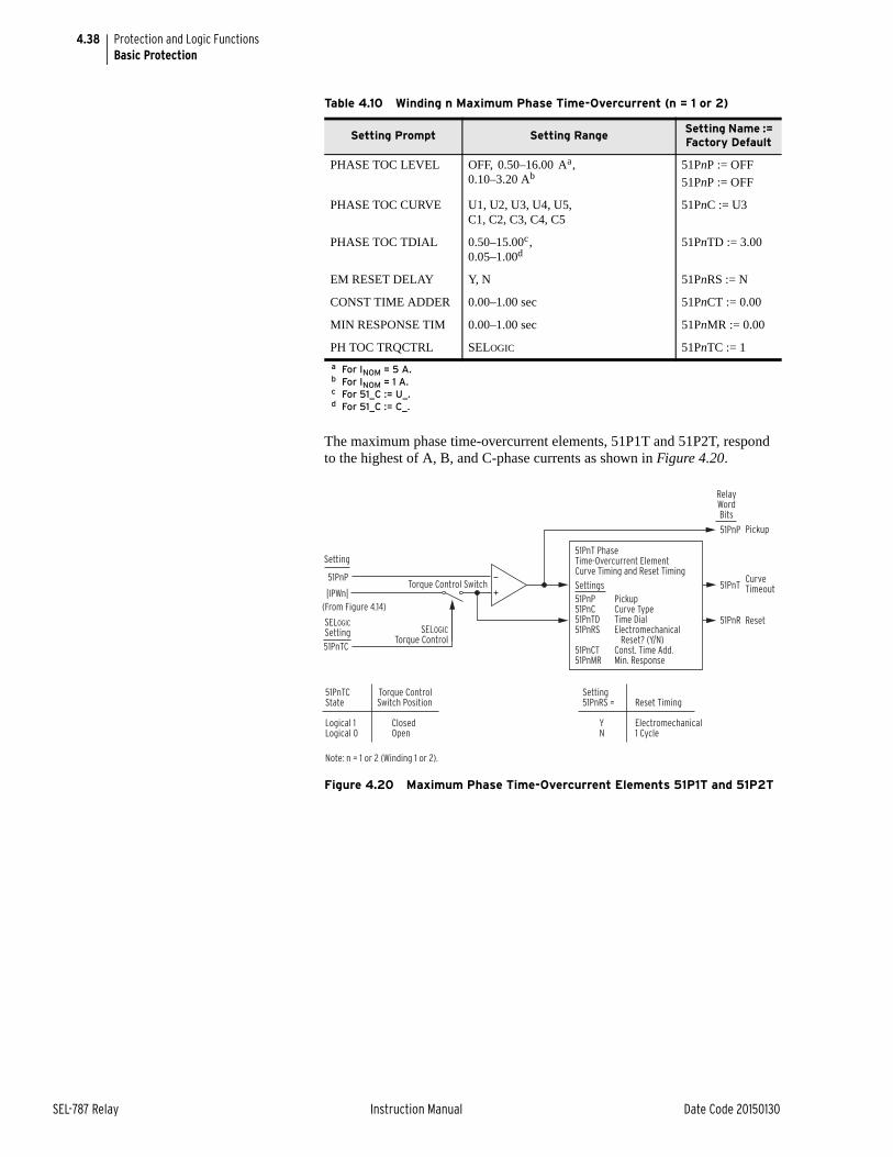
4.38
SEL-787 Relay Instruction Manual Date Code 20150130
Protection and Logic FunctionsBasic Protection
The maximum phase time-overcurrent elements, 51P1T and 51P2T, respond to the highest of A, B, and C-phase currents as shown in Figure 4.20.
Figure 4.20 Maximum Phase Time-Overcurrent Elements 51P1T and 51P2T
Table 4.10 Winding n Maximum Phase Time-Overcurrent (n = 1 or 2)
Setting Prompt Setting Range Setting Name := Factory Default
PHASE TOC LEVEL OFF, 0.50–16.00 Aa,0.10–3.20 Ab
a For INOM = 5 A.b For INOM = 1 A.
51PnP := OFF
51PnP := OFF
PHASE TOC CURVE U1, U2, U3, U4, U5, C1, C2, C3, C4, C5
51PnC := U3
PHASE TOC TDIAL 0.50–15.00c,0.05–1.00d
c For 51_C := U_.d For 51_C := C_.
51PnTD := 3.00
EM RESET DELAY Y, N 51PnRS := N
CONST TIME ADDER 0.00–1.00 sec 51PnCT := 0.00
MIN RESPONSE TIM 0.00–1.00 sec 51PnMR := 0.00
PH TOC TRQCTRL SELOGIC 51PnTC := 1
51PnP
|IPWn|
Setting
51PnTC
Torque Control Switch
SELOGIC Torque Control
Pickup
Curve Timeout
Reset
51PnP
51PnR
51PnT
51PnTC Torque ControlState Switch Position
Logical 1 ClosedLogical 0 Open
Setting 51PnRS = Reset Timing
Y Electromechanical N 1 Cycle
RelayWordBits
SELOGICSetting
(From Figure 4.14)
Note: n = 1 or 2 (Winding 1 or 2).
51PnT PhaseTime-Overcurrent ElementCurve Timing and Reset Timing
51PnP Pickup51PnC Curve Type51PnTD Time Dial51PnRS Electromechanical Reset? (Y/N)51PnCT Const. Time Add.51PnMR Min. Response
Settings
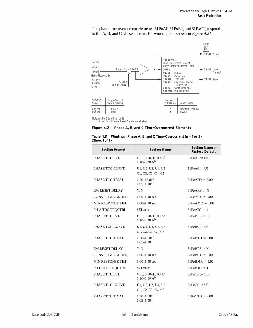
4.39
Date Code 20150130 Instruction Manual SEL-787 Relay
Protection and Logic FunctionsBasic Protection
The phase time-overcurrent elements, 51PnAT, 51PnBT, and 51PnCT, respond to the A, B, and C-phase currents for winding n as shown in Figure 4.21.
Figure 4.21 Phase A, B, and C Time-Overcurrent Elements
Table 4.11 Winding n Phase A, B, and C Time-Overcurrent (n = 1 or 2) (Sheet 1 of 2)
Setting Prompt Setting Range Setting Name := Factory Default
PHASE TOC LVL OFF, 0.50–16.00 Aa
0.10–3.20 Ab51PnAP := OFF
PHASE TOC CURVE U1, U2, U3, U4, U5,
C1, C2, C3, C4, C5
51PnAC := U3
PHASE TOC TDIAL 0.50–15.00c
0.05–1.00d51PnATD := 3.00
EM RESET DELAY Y, N 51PnARS := N
CONST TIME ADDER 0.00–1.00 sec 51PnACT := 0.00
MIN RESPONSE TIM 0.00–1.00 sec 51PnAMR := 0.00
PH A TOC TRQCTRL SELOGIC 51PnATC := 1
PHASE TOC LVL OFF, 0.50–16.00 Aa
0.10–3.20 Ab51PnBP := OFF
PHASE TOC CURVE U1, U2, U3, U4, U5,
C1, C2, C3, C4, C5
51PnBC := U3
PHASE TOC TDIAL 0.50–15.00c
0.05–1.00d51PnBTD := 3.00
EM RESET DELAY Y, N 51PnBRS := N
CONST TIME ADDER 0.00–1.00 sec 51PnBCT := 0.00
MIN RESPONSE TIM 0.00–1.00 sec 51PnBMR := 0.00
PH B TOC TRQCTRL SELOGIC 51PnBTC := 1
PHASE TOC LVL OFF, 0.50–16.00 Aa
0.10–3.20 Ab51PnCP := OFF
PHASE TOC CURVE U1, U2, U3, U4, U5,
C1, C2, C3, C4, C5
51PnCC := U3
PHASE TOC TDIAL 0.50–15.00c
0.05–1.00d51PnCTD := 3.00
51PnAP
|IAWn|
Setting
51PnATC
Torque Control Switch
SELOGICTorque Control
51PnAP Pickup
51PnAR Reset
51PnAT Curve Timeout
51PnATC Torque ControlState Switch Position
Logical 1 ClosedLogical 0 Open
Setting 51PnARS = Reset Timing
Y Electromechanical N 1 Cycle
RelayWordBits
SELOGICSetting
(From Figure 4.14)
Note: n = 1 or 2 (Winding 1 or 2). Shown for A Phase (phases B and C are similar).
51PnAT PhaseTime-Overcurrent ElementCurve Timing and Reset Timing
51PnAP Pickup51PnAC Curve Type51PnATD Time Dial51PnARS Electromechanical Reset? (Y/N)51PnACT Const. Time Add.51PnAMR Min. Response
Settings
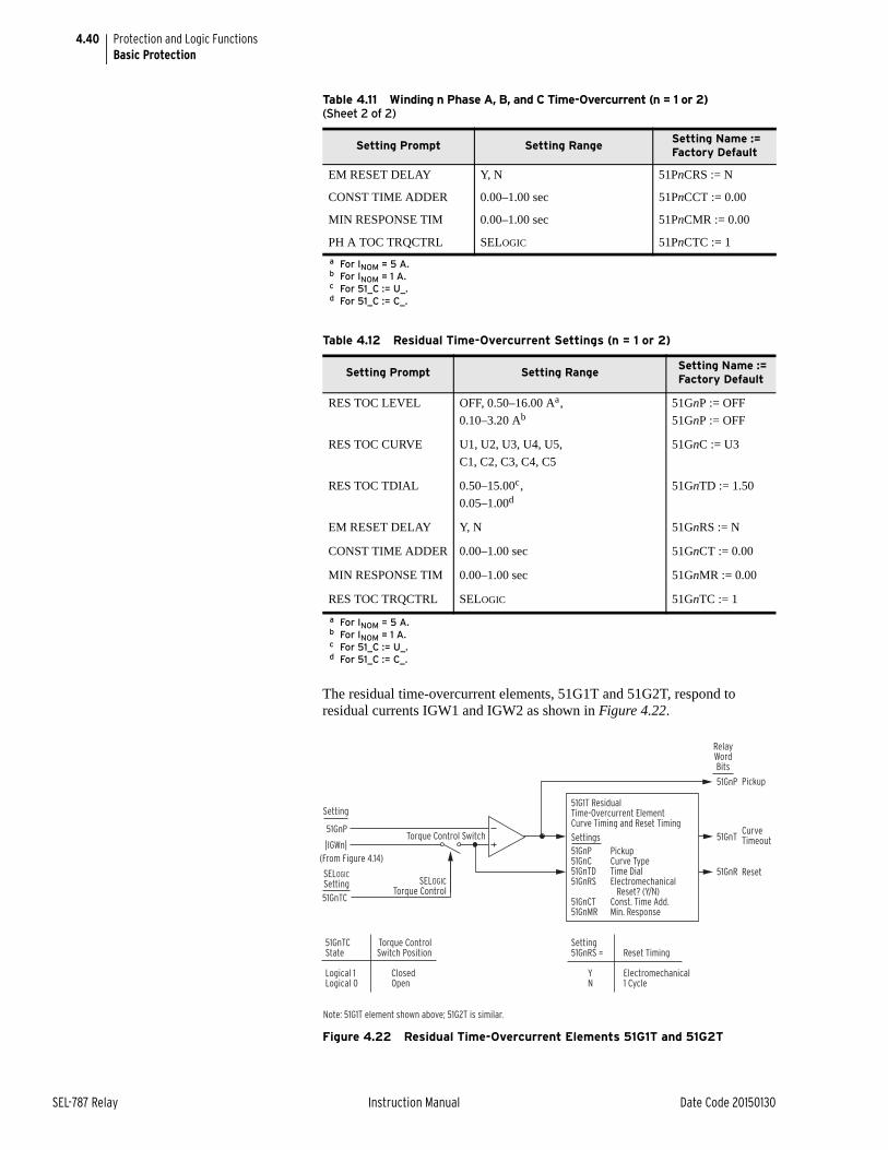
4.40
SEL-787 Relay Instruction Manual Date Code 20150130
Protection and Logic FunctionsBasic Protection
The residual time-overcurrent elements, 51G1T and 51G2T, respond to residual currents IGW1 and IGW2 as shown in Figure 4.22.
Figure 4.22 Residual Time-Overcurrent Elements 51G1T and 51G2T
EM RESET DELAY Y, N 51PnCRS := N
CONST TIME ADDER 0.00–1.00 sec 51PnCCT := 0.00
MIN RESPONSE TIM 0.00–1.00 sec 51PnCMR := 0.00
PH A TOC TRQCTRL SELOGIC 51PnCTC := 1
a For INOM = 5 A.b For INOM = 1 A.c For 51_C := U_.d For 51_C := C_.
Table 4.12 Residual Time-Overcurrent Settings (n = 1 or 2)
Setting Prompt Setting Range Setting Name := Factory Default
RES TOC LEVEL OFF, 0.50–16.00 Aa,
0.10–3.20 Ab
a For INOM = 5 A.b For INOM = 1 A.
51GnP := OFF
51GnP := OFF
RES TOC CURVE U1, U2, U3, U4, U5,
C1, C2, C3, C4, C5
51GnC := U3
RES TOC TDIAL 0.50–15.00c,
0.05–1.00d
c For 51_C := U_.d For 51_C := C_.
51GnTD := 1.50
EM RESET DELAY Y, N 51GnRS := N
CONST TIME ADDER 0.00–1.00 sec 51GnCT := 0.00
MIN RESPONSE TIM 0.00–1.00 sec 51GnMR := 0.00
RES TOC TRQCTRL SELOGIC 51GnTC := 1
Table 4.11 Winding n Phase A, B, and C Time-Overcurrent (n = 1 or 2) (Sheet 2 of 2)
Setting Prompt Setting Range Setting Name := Factory Default
51GnP
|IGWn|
Setting
51GnTC
Torque Control Switch
SELOGIC Torque Control
Pickup
Curve Timeout
Reset
51GnP
51GnR
51GnT
51GnTC Torque ControlState Switch Position
Logical 1 ClosedLogical 0 Open
Setting 51GnRS = Reset Timing
Y Electromechanical N 1 Cycle
RelayWordBits
SELOGICSetting
(From Figure 4.14)
Note: 51G1T element shown above; 51G2T is similar.
51G1T ResidualTime-Overcurrent ElementCurve Timing and Reset Timing
51GnP Pickup51GnC Curve Type51GnTD Time Dial51GnRS Electromechanical Reset? (Y/N)51GnCT Const. Time Add.51GnMR Min. Response
Settings
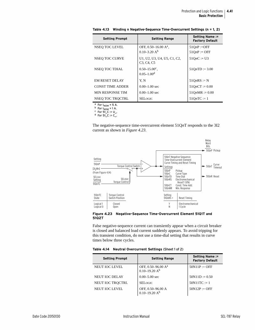
4.41
Date Code 20150130 Instruction Manual SEL-787 Relay
Protection and Logic FunctionsBasic Protection
The negative-sequence time-overcurrent element 51QnT responds to the 3I2 current as shown in Figure 4.23.
Figure 4.23 Negative-Sequence Time-Overcurrent Element 51Q1T and 51Q2T
False negative-sequence current can transiently appear when a circuit breaker is closed and balanced load current suddenly appears. To avoid tripping for this transient condition, do not use a time-dial setting that results in curve times below three cycles.
Table 4.13 Winding n Negative-Sequence Time-Overcurrent Settings (n = 1, 2)
Setting Prompt Setting Range Setting Name := Factory Default
NSEQ TOC LEVEL OFF, 0.50–16.00 Aa,
0.10–3.20 Ab
a For INOM = 5 A.b For INOM = 1 A.
51QnP :=OFF
51QnP := OFF
NSEQ TOC CURVE U1, U2, U3, U4, U5, C1, C2, C3, C4, C5
51QnC := U3
NSEQ TOC TDIAL 0.50–15.00c,
0.05–1.00d
c For 51_C := U_.d For 51_C := C_.
51QnTD := 3.00
EM RESET DELAY Y, N 51QnRS := N
CONST TIME ADDER 0.00–1.00 sec 51QnCT := 0.00
MIN RESPONSE TIM 0.00–1.00 sec 51QnMR := 0.00
NSEQ TOC TRQCTRL SELOGIC 51QnTC := 1
Table 4.14 Neutral Overcurrent Settings (Sheet 1 of 2)
Setting Prompt Setting Range Setting Name := Factory Default
NEUT IOC LEVEL OFF, 0.50–96.00 Aa
0.10–19.20 Ab50N11P := OFF
NEUT IOC DELAY 0.00–5.00 sec 50N11D := 0.50
NEUT IOC TRQCTRL SELOGIC 50N11TC := 1
NEUT IOC LEVEL OFF, 0.50–96.00 A0.10–19.20 Ab
50N12P := OFF
51QnTC
SELOGIC Torque Control
SELOGICSetting
(From Figure 4.14)
51QnP
|3I2Wn|
Setting
Torque Control Switch
Pickup
Curve Timeout
Reset
51QnP
51QnR
51QnT
51QnTC Torque ControlState Switch Position
Logical 1 ClosedLogical 0 Open
Setting 51QnRS = Reset Timing
Y Electromechanical N 1 Cycle
RelayWordBits
51QnT Negative-SequenceTime-Overcurrent ElementCurve Timing and Reset Timing
51QnP Pickup51QnC Curve Type51QnTD Time Dial51QnRS Electromechanical Reset? (Y/N)51QnCT Const. Time Add.51QnMR Min. Response
Settings
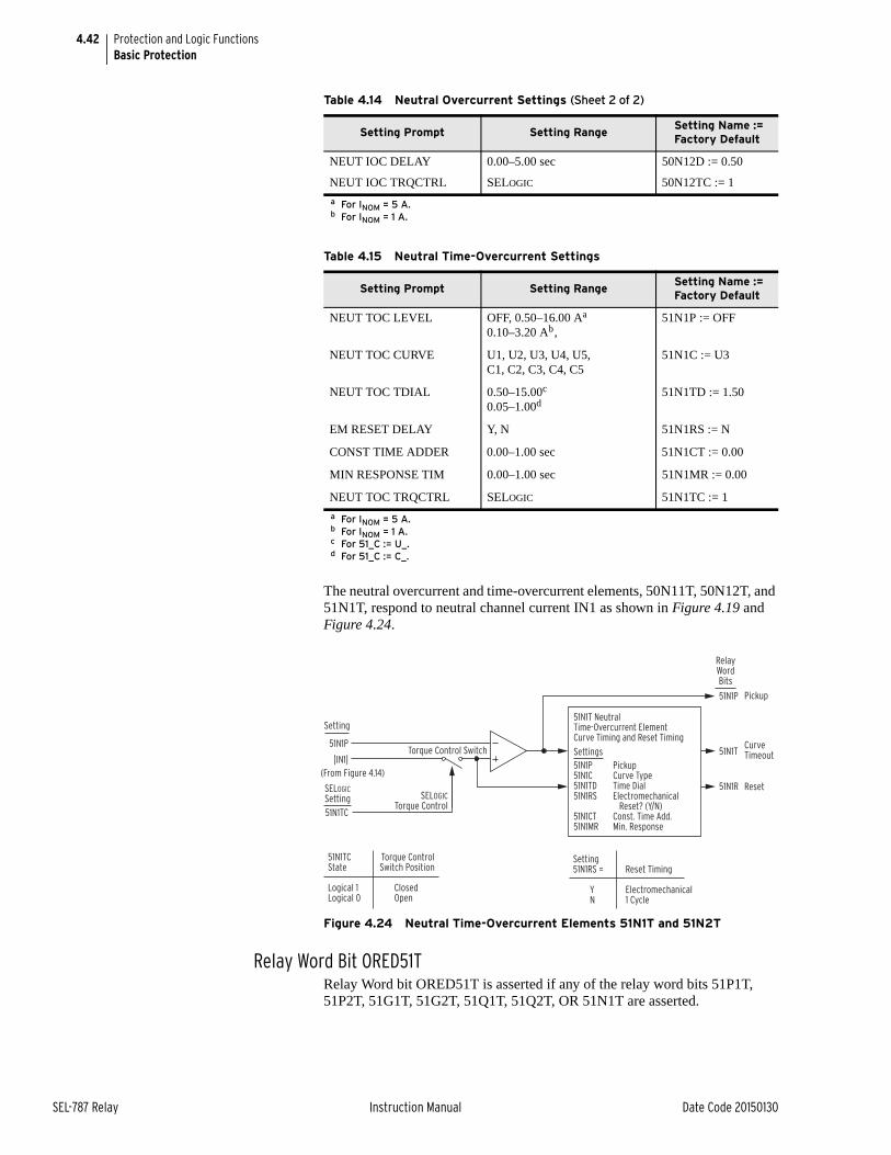
4.42
SEL-787 Relay Instruction Manual Date Code 20150130
Protection and Logic FunctionsBasic Protection
The neutral overcurrent and time-overcurrent elements, 50N11T, 50N12T, and 51N1T, respond to neutral channel current IN1 as shown in Figure 4.19 and Figure 4.24.
Figure 4.24 Neutral Time-Overcurrent Elements 51N1T and 51N2T
Relay Word Bit ORED51TRelay Word bit ORED51T is asserted if any of the relay word bits 51P1T, 51P2T, 51G1T, 51G2T, 51Q1T, 51Q2T, OR 51N1T are asserted.
NEUT IOC DELAY 0.00–5.00 sec 50N12D := 0.50
NEUT IOC TRQCTRL SELOGIC 50N12TC := 1
a For INOM = 5 A.b For INOM = 1 A.
Table 4.15 Neutral Time-Overcurrent Settings
Setting Prompt Setting Range Setting Name := Factory Default
NEUT TOC LEVEL OFF, 0.50–16.00 Aa
0.10–3.20 Ab,
a For INOM = 5 A.b For INOM = 1 A.
51N1P := OFF
NEUT TOC CURVE U1, U2, U3, U4, U5, C1, C2, C3, C4, C5
51N1C := U3
NEUT TOC TDIAL 0.50–15.00c
0.05–1.00d
c For 51_C := U_.d For 51_C := C_.
51N1TD := 1.50
EM RESET DELAY Y, N 51N1RS := N
CONST TIME ADDER 0.00–1.00 sec 51N1CT := 0.00
MIN RESPONSE TIM 0.00–1.00 sec 51N1MR := 0.00
NEUT TOC TRQCTRL SELOGIC 51N1TC := 1
Table 4.14 Neutral Overcurrent Settings (Sheet 2 of 2)
Setting Prompt Setting Range Setting Name := Factory Default
51N1P
|IN1|
Setting
51N1TC
Torque Control Switch
SELOGIC Torque Control
Pickup
Curve Timeout
Reset
51N1P
51N1R
51N1T
51N1TC Torque ControlState Switch Position
Logical 1 ClosedLogical 0 Open
Setting 51N1RS = Reset Timing
Y Electromechanical N 1 Cycle
RelayWordBits
SELOGICSetting
(From Figure 4.14)
51N1T NeutralTime-Overcurrent ElementCurve Timing and Reset Timing
51N1P Pickup51N1C Curve Type51N1TD Time Dial51N1RS Electromechanical Reset? (Y/N)51N1CT Const. Time Add.51N1MR Min. Response
Settings
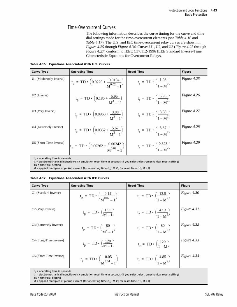
4.43
Date Code 20150130 Instruction Manual SEL-787 Relay
Protection and Logic FunctionsBasic Protection
Time-Overcurrent CurvesThe following information describes the curve timing for the curve and time dial settings made for the time-overcurrent elements (see Table 4.16 and Table 4.17). The U.S. and IEC time-overcurrent relay curves are shown in Figure 4.25 through Figure 4.34. Curves U1, U2, and U3 (Figure 4.25 through Figure 4.27) conform to IEEE C37.112-1996 IEEE Standard Inverse-Time Characteristic Equations for Overcurrent Relays.
Table 4.16 Equations Associated With U.S. Curves
Curve Type Operating Time Reset Time Figure
U1 (Moderately Inverse)
Figure 4.25
U2 (Inverse)
Figure 4.26
U3 (Very Inverse)
Figure 4.27
U4 (Extremely Inverse)
Figure 4.28
U5 (Short-Time Inverse)
Figure 4.29
tp = operating time in secondstr = electromechanical induction-disk emulation reset time in seconds (if you select electromechanical reset setting)TD = time-dial settingM = applied multiples of pickup current [for operating time (tp), M >1; for reset time (tr), M 1]
Table 4.17 Equations Associated With IEC Curves
Curve Type Operating Time Reset Time Figure
C1 (Standard Inverse)
Figure 4.30
C2 (Very Inverse)
Figure 4.31
C3 (Extremely Inverse)
Figure 4.32
C4 (Long-Time Inverse)
Figure 4.33
C5 (Short-Time Inverse)
Figure 4.34
tp = operating time in secondstr = electromechanical induction-disk emulation reset time in seconds (if you select electromechanical reset setting)TD = time-dial settingM = applied multiples of pickup current [for operating time (tp), M >1; for reset time (tr), M 1]
tp TD 0.0226 0.0104
M0.02
1–----------------------+
• = tr TD1.08
1 M2
–---------------- • =
tp TD 0.180 5.95
M2
1–----------------+
• = tr TD5.95
1 M2
–---------------- • =
tp TD 0.0963 3.88
M2
1–----------------+
• = tr TD3.88
1 M2
–---------------- • =
tp TD 0.0352 5.67
M2
1–----------------+
• = tr TD5.67
1 M2
–---------------- • =
tp TD 0.00262 0.00342
M0.02
1–----------------------+
• = tr TD0.323
1 M2
–---------------- • =
tp TD0.14
M0.02
1–---------------------- • = tr TD
13.5
1 M2
–---------------- • =
tp TD13.5
M 1–-------------- • = tr TD
47.3
1 M2
–---------------- • =
tp TD80
M2
1–---------------- • = tr TD
80
1 M2
–---------------- • =
tp TD120
M 1–-------------- • = tr TD
1201 M–-------------- • =
tp TD0.05
M0.04
1–---------------------- • = tr TD
4.85
1 M2
–---------------- • =
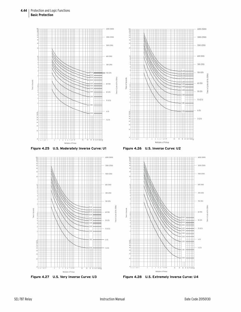
4.44
SEL-787 Relay Instruction Manual Date Code 20150130
Protection and Logic FunctionsBasic Protection
Figure 4.25 U.S. Moderately Inverse Curve: U1 Figure 4.26 U.S. Inverse Curve: U2
Figure 4.27 U.S. Very Inverse Curve: U3 Figure 4.28 U.S. Extremely Inverse Curve: U4
0.50
6.005.00
4.00
3.00
2.00
1.00
15.00
12.0010.00
8.00
.01.5 .6 .7 .8 .9 1
.02
.03
.04
.05
.09
.07
.06
.08
.1
.2
.3
.4
.5
.7
.6
.9
.8
1
42 3 5 6 7 8 9 10 4020 30 7050 60 80 90 100
80
10
2
3
6
4
5
7
98
20
50
30
40
6070
10090
Tim
e in
Sec
onds
Multiples of Pickup
Tim
e in
Cyc
les
60 H
z (5
0Hz)
3 (2.5)
6 (5)
15 (12.5)
30 (25)
60 (50)
600 (500)
150 (125)
300 (250)
1500 (1250)
3000 (2500)
6000 (5000)
0.50
6.005.004.00
3.00
2.00
1.00
15.0012.0010.008.00
.01.5 .6 .7 .8 .9 1
.02
.03
.04
.05
.09
.07
.06
.08
.1
.2
.3
.4
.5
.7
.6
.9
.8
1
42 3 5 6 7 8 9 10 4020 30 7050 60 80 90 100
80
10
2
3
6
4
5
7
98
20
50
30
40
6070
10090
Tim
e in
Sec
onds
Multiples of Pickup
Tim
e in
Cyc
les
60 H
z (5
0Hz)
3 (2.5)
6 (5)
15 (12.5)
30 (25)
60 (50)
600 (500)
150 (125)
300 (250)
1500 (1250)
3000 (2500)
6000 (5000)
12.00
1.00
0.50
10.00
8.00
6.005.00
4.00
3.00
2.00
15.00
.01.5 .6 .7 .8 .9 1
.02
.03
.04
.05
.09
.07
.06
.08
.1
.2
.3
.4
.5
.7
.6
.9
.8
1
42 3 5 6 7 8 9 10 4020 30 7050 60 80 90 100
80
10
2
3
6
4
5
7
98
20
50
30
40
6070
10090
Tim
e in
Sec
onds
Multiples of Pickup
Tim
e in
Cyc
les
60 H
z (5
0Hz)
3 (2.5)
6 (5)
15 (12.5)
30 (25)
60 (50)
600 (500)
150 (125)
300 (250)
1500 (1250)
3000 (2500)
6000 (5000)
3.00
2.00
1.00
0.50
15.00
12.0010.00
8.00
6.005.00
4.00
.01.5 .6 .7 .8 .9 1
.02
.03
.04
.05
.09
.07
.06
.08
.1
.2
.3
.4
.5
.7
.6
.9
.8
1
42 3 5 6 7 8 9 10 4020 30 7050 60 80 90 100
80
10
2
3
6
4
5
7
98
20
50
30
40
6070
10090
Tim
e in
Sec
onds
Multiples of Pickup
Tim
e in
Cyc
les
60 H
z (5
0Hz)
3 (2.5)
6 (5)
15 (12.5)
30 (25)
60 (50)
600 (500)
150 (125)
300 (250)
1500 (1250)
3000 (2500)
6000 (5000)
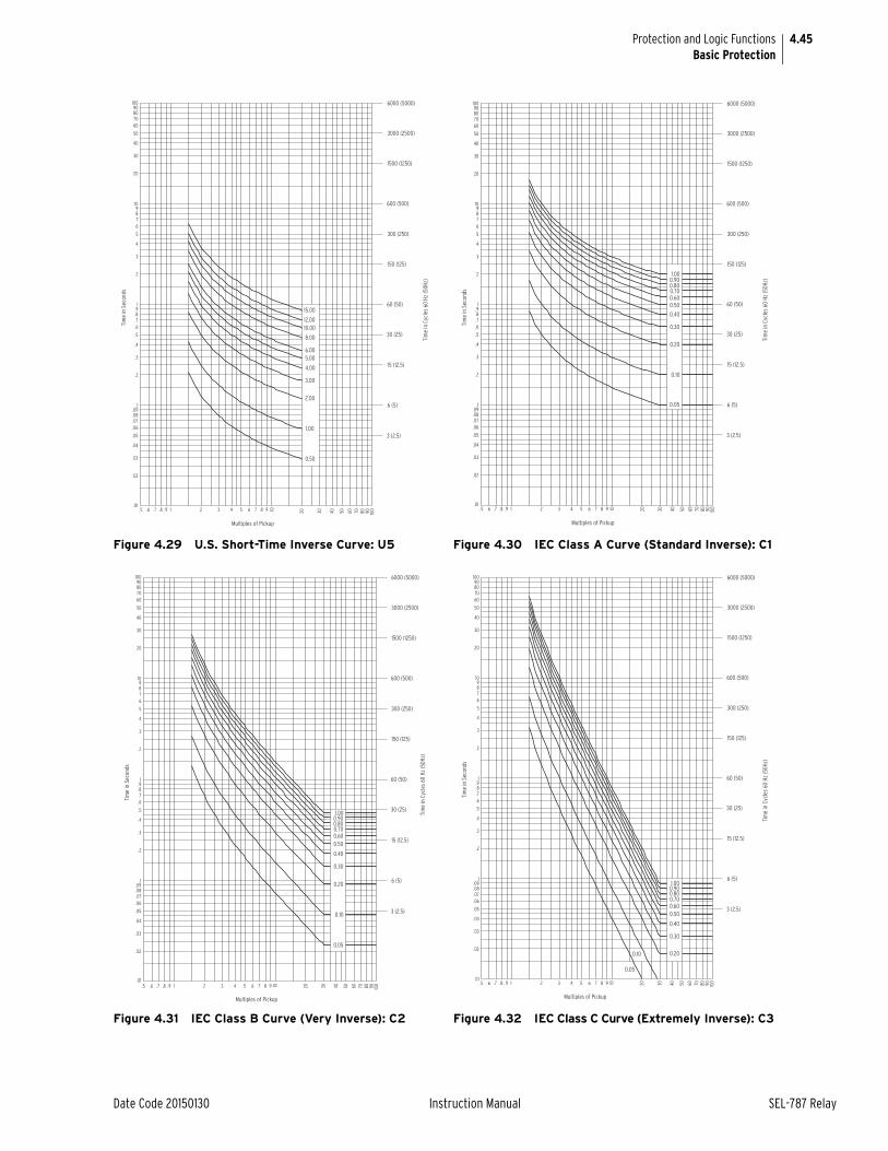
4.45
Date Code 20150130 Instruction Manual SEL-787 Relay
Protection and Logic FunctionsBasic Protection
Figure 4.29 U.S. Short-Time Inverse Curve: U5 Figure 4.30 IEC Class A Curve (Standard Inverse): C1
Figure 4.31 IEC Class B Curve (Very Inverse): C2 Figure 4.32 IEC Class C Curve (Extremely Inverse): C3
0.50
1.00
2.00
6.00
3.00
4.00
5.00
10.00
8.00
12.00
15.00
.01.5 .6 .7 .8 1.9
.02
.03
.04
.05
.06
.07
.1
.08
.09
.2
.3
.4
.5
.6
1
.7
.8
.9
2 3 4 5 6 7 8 109 20 30 5040 60 1009070 80
80
9
2
3
4
5
678
10
20
30
40
50
6070
90100
Tim
e in
Sec
onds
Multiples of Pickup
Tim
e in
Cyc
les
60 H
z (5
0Hz)
3 (2.5)
6 (5)
15 (12.5)
60 (50)
30 (25)
150 (125)
300 (250)
1500 (1250)
600 (500)
3000 (2500)
6000 (5000)
0.60
0.05
0.50
0.40
0.30
0.20
0.10
1.000.900.800.70
.01.5 .6 .7 .8 .9 1
.02
.03
.04
.05
.09
.07
.06
.08
.1
.2
.3
.4
.5
.7
.6
.9
.8
1
42 3 5 6 7 8 9 10 4020 30 7050 60 80 90 100
80
10
2
3
6
4
5
7
98
20
50
30
40
6070
10090
Tim
e in
Sec
onds
Multiples of Pickup
Tim
e in
Cyc
les
60 H
z (5
0Hz)
3 (2.5)
6 (5)
15 (12.5)
30 (25)
60 (50)
600 (500)
150 (125)
300 (250)
1500 (1250)
3000 (2500)
6000 (5000)
0.30
0.20
0.10
0.05
1.000.900.800.700.600.50
0.40
.01.5 .6 .7 .8 .9 1
.02
.03
.04
.05
.09
.07
.06
.08
.1
.2
.3
.4
.5
.7
.6
.9
.8
1
42 3 5 6 7 8 9 10 4020 30 7050 60 80 90 100
80
10
2
3
6
4
5
7
98
20
50
30
40
6070
10090
Tim
e in
Sec
onds
Multiples of Pickup
Tim
e in
Cyc
les
60 H
z (5
0Hz)
3 (2.5)
6 (5)
15 (12.5)
30 (25)
60 (50)
600 (500)
150 (125)
300 (250)
1500 (1250)
3000 (2500)
6000 (5000)
.01.5 .6 .7 .8 .9 1
.02
.03
.04
.05
.09
.07
.06
.08
.1
.2
.3
.4
.5
.7
.6
.9
.8
1
42 3 5 6 7 8 9 10 4020 30 7050 60 80 90 100
80
10
2
3
6
4
5
7
98
20
50
30
40
6070
10090
0.200.10
0.05
1.000.900.800.700.600.50
0.40
0.30
Tim
e in
Sec
onds
Multiples of Pickup
Tim
e in
Cyc
les
60 H
z (5
0Hz)
3 (2.5)
6 (5)
15 (12.5)
30 (25)
60 (50)
600 (500)
150 (125)
300 (250)
1500 (1250)
3000 (2500)
6000 (5000)
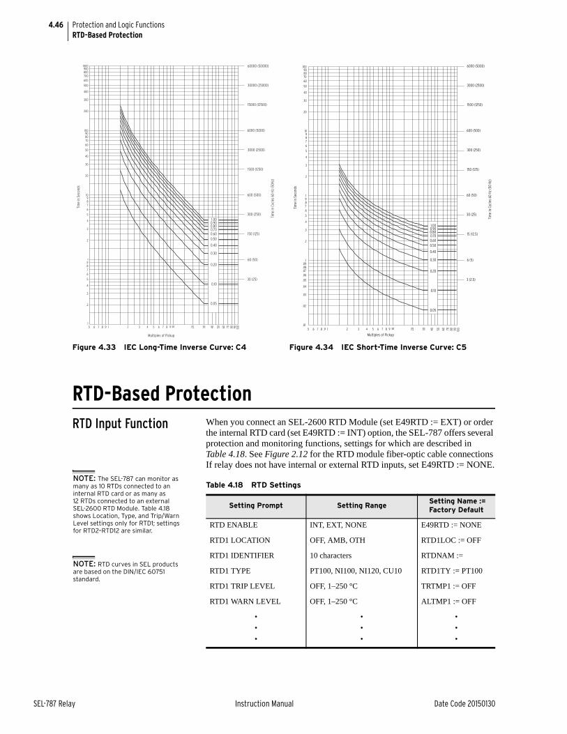
4.46
SEL-787 Relay Instruction Manual Date Code 20150130
Protection and Logic FunctionsRTD-Based Protection
RTD-Based ProtectionRTD Input Function When you connect an SEL-2600 RTD Module (set E49RTD := EXT) or order
the internal RTD card (set E49RTD := INT) option, the SEL-787 offers several protection and monitoring functions, settings for which are described in Table 4.18. See Figure 2.12 for the RTD module fiber-optic cable connections If relay does not have internal or external RTD inputs, set E49RTD := NONE.
Figure 4.33 IEC Long-Time Inverse Curve: C4 Figure 4.34 IEC Short-Time Inverse Curve: C5
0.20
0.10
0.05
1.000.900.800.700.600.50
0.40
0.30
.7.6.5.1
.9.8 1
.4
.2
.3
.5
.6
.8
.7
.91
2
3
4
5
76
42 3 765 1098 4020 30 7050 60 80 90 100
50
98
10
20
30
40
300
200
100
80
6070
90
1000900800700600
500
400
Tim
e in
Sec
onds
Multiples of Pickup
Tim
e in
Cyc
les
60 H
z (5
0Hz)
30 (25)
60 (50)
150 (125)
300 (250)
3000 (2500)
600 (500)
1500 (1250)
6000 (5000)
15000 (12500)
30000 (25000)
60000 (50000)
10
20
30
40
50
60708090
100
1
2
3
4
5
6789
.1
.2
.3
.4
.5
.6
.7
.8
.9
.01
.02
.03
.04
.05
.06
.07
.08
.09
1001 2 3 4 5 6 7 8 9.5 .6 .7 .8 .9 908070605040302010
Tim
e in
Sec
onds
Tim
e in
Cyc
les
60 H
z (5
0 Hz
)
6000 (5000)
3000 (2500)
1500 (1250)
600 (500)
300 (250)
150 (125)
60 (50)
30 (25)
15 (12.5)
6 (5)
3 (2.5)
Multiples of Pickup
0.05
0.10
0.20
0.30
0.40
0.500.600.700.800.901.00
Table 4.18 RTD Settings
Setting Prompt Setting Range Setting Name := Factory Default
RTD ENABLE INT, EXT, NONE E49RTD := NONE
RTD1 LOCATION OFF, AMB, OTH RTD1LOC := OFF
RTD1 IDENTIFIER 10 characters RTDNAM :=
RTD1 TYPE PT100, NI100, NI120, CU10 RTD1TY := PT100
RTD1 TRIP LEVEL OFF, 1–250 °C TRTMP1 := OFF
RTD1 WARN LEVEL OFF, 1–250 °C ALTMP1 := OFF
•
•
•
•
•
•
•
•
•
NOTE: The SEL-787 can monitor as many as 10 RTDs connected to an internal RTD card or as many as 12 RTDs connected to an external SEL-2600 RTD Module. Table 4.18 shows Location, Type, and Trip/Warn Level settings only for RTD1; settings for RTD2–RTD12 are similar.
NOTE: RTD curves in SEL products are based on the DIN/IEC 60751 standard.

4.47
Date Code 20150130 Instruction Manual SEL-787 Relay
Protection and Logic FunctionsRTD-Based Protection
RTD Location
The relay allows you to independently define the location of each monitored RTD by using the RTD location settings.
Define the RTD location settings through use of the following suggestions:
➤ If an RTD is not connected to an input or has failed in place and will not be replaced, set the RTD location for that input equal to OFF.
➤ For the input connected to an RTD measuring ambient air temperature, set the RTD location equal to AMB. Only one ambient temperature RTD is allowed.
➤ For inputs connected to monitor temperatures of apparatus, such as transformer oil and winding temperature, set the RTD location equal to OTH. Use the RTD identifier setting to assign an appropriate name to the RTD, for example set RTD1NAM := XFRMR1 OIL.
If an RTD location setting is equal to OFF, the relay does not request that an RTD type setting be entered for that input.
RTD TypeThe four available RTD types are:
➤ 100-ohm platinum (PT100)
➤ 100-ohm nickel (NI100)
➤ 120-ohm nickel (NI120)
➤ 10-ohm copper (CU10)
RTD Trip/Warning LevelsThe SEL-787 provides temperature warnings and trips through use of the RTD temperature measurements and the warning and trip temperature settings in Table 4.18.
The relay issues a temperature warning if any of the healthy RTDs indicates a temperature greater than the relay RTD warning temperature setting. The relay issues a temperature trip if one of the healthy RTDs indicates a temperature greater than the RTD trip temperature setting.
To disable any of the temperature warning or trip functions, set the appropriate temperature setting to OFF.
Only healthy RTDs can contribute temperatures to the warning and trip functions. The relay includes specific logic to indicate if RTD leads are shorted or open.
Table 4.19 lists the RTD resistance versus temperature for the four supported RTD types.
Table 4.19 RTD Resistance Versus Temperature (Sheet 1 of 2)
Temp(°F)
Temp(°C)
100Platinum
120Nickel
100Nickel
10Copper
–58 –50.00 80.31 86.17 74.30 7.10
–40 –40.00 84.27 92.76 79.10 7.49
–22 –30.00 88.22 99.41 84.20 7.88
NOTE: To improve security, RTD ALARM and TRIP are delayed by approximately 6 seconds.
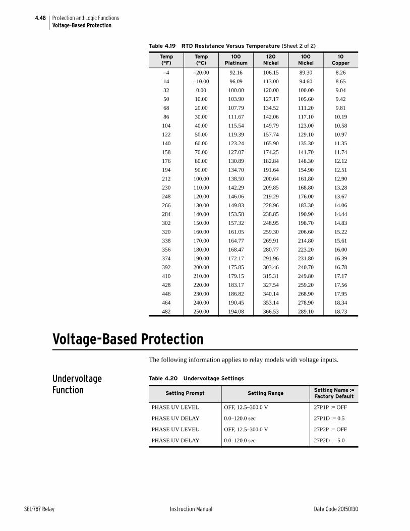
4.48
SEL-787 Relay Instruction Manual Date Code 20150130
Protection and Logic FunctionsVoltage-Based Protection
Voltage-Based ProtectionThe following information applies to relay models with voltage inputs.
Undervoltage Function
–4 –20.00 92.16 106.15 89.30 8.26
14 –10.00 96.09 113.00 94.60 8.65
32 0.00 100.00 120.00 100.00 9.04
50 10.00 103.90 127.17 105.60 9.42
68 20.00 107.79 134.52 111.20 9.81
86 30.00 111.67 142.06 117.10 10.19
104 40.00 115.54 149.79 123.00 10.58
122 50.00 119.39 157.74 129.10 10.97
140 60.00 123.24 165.90 135.30 11.35
158 70.00 127.07 174.25 141.70 11.74
176 80.00 130.89 182.84 148.30 12.12
194 90.00 134.70 191.64 154.90 12.51
212 100.00 138.50 200.64 161.80 12.90
230 110.00 142.29 209.85 168.80 13.28
248 120.00 146.06 219.29 176.00 13.67
266 130.00 149.83 228.96 183.30 14.06
284 140.00 153.58 238.85 190.90 14.44
302 150.00 157.32 248.95 198.70 14.83
320 160.00 161.05 259.30 206.60 15.22
338 170.00 164.77 269.91 214.80 15.61
356 180.00 168.47 280.77 223.20 16.00
374 190.00 172.17 291.96 231.80 16.39
392 200.00 175.85 303.46 240.70 16.78
410 210.00 179.15 315.31 249.80 17.17
428 220.00 183.17 327.54 259.20 17.56
446 230.00 186.82 340.14 268.90 17.95
464 240.00 190.45 353.14 278.90 18.34
482 250.00 194.08 366.53 289.10 18.73
Table 4.19 RTD Resistance Versus Temperature (Sheet 2 of 2)
Temp(°F)
Temp(°C)
100Platinum
120Nickel
100Nickel
10Copper
Table 4.20 Undervoltage Settings
Setting Prompt Setting Range Setting Name := Factory Default
PHASE UV LEVEL OFF, 12.5–300.0 V 27P1P := OFF
PHASE UV DELAY 0.0–120.0 sec 27P1D := 0.5
PHASE UV LEVEL OFF, 12.5–300.0 V 27P2P := OFF
PHASE UV DELAY 0.0–120.0 sec 27P2D := 5.0
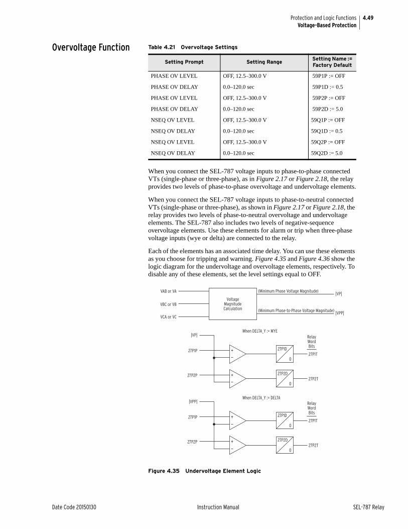
4.49
Date Code 20150130 Instruction Manual SEL-787 Relay
Protection and Logic FunctionsVoltage-Based Protection
Overvoltage Function
When you connect the SEL-787 voltage inputs to phase-to-phase connected VTs (single-phase or three-phase), as in Figure 2.17 or Figure 2.18, the relay provides two levels of phase-to-phase overvoltage and undervoltage elements.
When you connect the SEL-787 voltage inputs to phase-to-neutral connected VTs (single-phase or three-phase), as shown in Figure 2.17 or Figure 2.18, the relay provides two levels of phase-to-neutral overvoltage and undervoltage elements. The SEL-787 also includes two levels of negative-sequence overvoltage elements. Use these elements for alarm or trip when three-phase voltage inputs (wye or delta) are connected to the relay.
Each of the elements has an associated time delay. You can use these elements as you choose for tripping and warning. Figure 4.35 and Figure 4.36 show the logic diagram for the undervoltage and overvoltage elements, respectively. To disable any of these elements, set the level settings equal to OFF.
Figure 4.35 Undervoltage Element Logic
Table 4.21 Overvoltage Settings
Setting Prompt Setting Range Setting Name := Factory Default
PHASE OV LEVEL OFF, 12.5–300.0 V 59P1P := OFF
PHASE OV DELAY 0.0–120.0 sec 59P1D := 0.5
PHASE OV LEVEL OFF, 12.5–300.0 V 59P2P := OFF
PHASE OV DELAY 0.0–120.0 sec 59P2D := 5.0
NSEQ OV LEVEL OFF, 12.5–300.0 V 59Q1P := OFF
NSEQ OV DELAY 0.0–120.0 sec 59Q1D := 0.5
NSEQ OV LEVEL OFF, 12.5–300.0 V 59Q2P := OFF
NSEQ OV DELAY 0.0–120.0 sec 59Q2D := 5.0
27P1P
|VP|
27P1D
027P1T
When DELTA_Y := WYE
When DELTA_Y := DELTA
27P2P 27P2D
027P2T
27P1D
027P1T
27P2D
027P2T
RelayWordBits
27P1P
|VPP|
27P2P
RelayWordBits
VAB or VA
VBC or VB
VCA or VC
VoltageMagnitudeCalculation
|VP|
|VPP|
(Minimum Phase Voltage Magnitude)
(Minimum Phase-to-Phase Voltage Magnitude)

4.50
SEL-787 Relay Instruction Manual Date Code 20150130
Protection and Logic FunctionsVoltage-Based Protection
Figure 4.36 Overvoltage Element Logic
Volts Per Hertz Elements
Overexcitation occurs when a transformer magnetic core becomes saturated. When this happens, stray flux is induced in nonlaminated components, causing overheating. In the SEL-787 Relay a volts/hertz element detects overexcitation. The SEL-787 provides a sensitive definite time volts/hertz element, plus a tripping element with a composite operating time. The relay calculates the present transformer volts/hertz as a percent of nominal, based on the present and nominal voltages and frequencies. The settings VNOM and FNOM define the nominal transformer voltage and frequency, respectively.
Figure 4.37 shows a logic diagram of the volts/hertz elements. If the torque-control 24TC SELOGIC control equation is true and the present volts/hertz exceed the 24D1P setting, the relay asserts the 24D1 Relay Word bit and starts the 24D1D timer. If the condition remains for 24D1D seconds, the relay asserts the 24D1T Relay Word bit. Typically, you should apply this element as an overexcitation alarm.
59P1P
|VP|
59P1D
059P1T
When DELTA_Y := WYE
When DELTA_Y := DELTA
59P2P 59P2D
059P2T
59P1D
059P1T
59P2D
059P2T
RelayWordBits
59P1P
|VPP|
59P2P
RelayWordBits
VAB or VA
VBC or VB
VCA or VC
VoltageMagnitudeCalculation
|VP|
|VPP|
(Maximum Phase Voltage Magnitude)
|3V2|(Negative Sequence Voltage Magnitude)
(Maximum Phase-to-Phase Voltage Magnitude)
59P1P, 59P2P, 59Q1P, 59Q2P = Settings
59Q1P
|3V2|
59Q1D
059Q1T
When DELTA_Y := WYE or DELTA
59Q2P 59Q2D
059Q2T
RelayWordBits
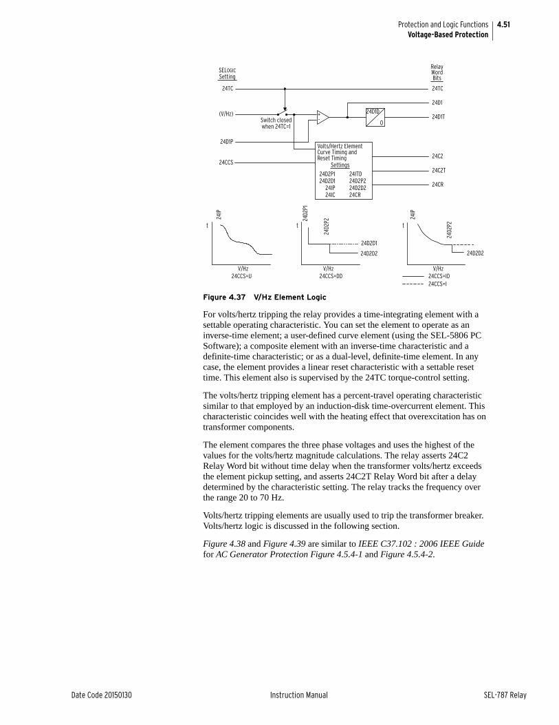
4.51
Date Code 20150130 Instruction Manual SEL-787 Relay
Protection and Logic FunctionsVoltage-Based Protection
Figure 4.37 V/Hz Element Logic
For volts/hertz tripping the relay provides a time-integrating element with a settable operating characteristic. You can set the element to operate as an inverse-time element; a user-defined curve element (using the SEL-5806 PC Software); a composite element with an inverse-time characteristic and a definite-time characteristic; or as a dual-level, definite-time element. In any case, the element provides a linear reset characteristic with a settable reset time. This element also is supervised by the 24TC torque-control setting.
The volts/hertz tripping element has a percent-travel operating characteristic similar to that employed by an induction-disk time-overcurrent element. This characteristic coincides well with the heating effect that overexcitation has on transformer components.
The element compares the three phase voltages and uses the highest of the values for the volts/hertz magnitude calculations. The relay asserts 24C2 Relay Word bit without time delay when the transformer volts/hertz exceeds the element pickup setting, and asserts 24C2T Relay Word bit after a delay determined by the characteristic setting. The relay tracks the frequency over the range 20 to 70 Hz.
Volts/hertz tripping elements are usually used to trip the transformer breaker. Volts/hertz logic is discussed in the following section.
Figure 4.38 and Figure 4.39 are similar to IEEE C37.102 : 2006 IEEE Guide for AC Generator Protection Figure 4.5.4-1 and Figure 4.5.4-2.
+-
24D1D
0
Settings
24D2P1
24D1
24D1T
24C2
24C2T
24CR
(V/Hz)
V/Hz
24D2
P1
24D2
P2
24IP
24D2D2
24CCS=DD
24IP
24D2
P2
V/Hz24CCS=ID
RelayWordBits
24TC
24D2D2
24CCS
V/Hz24CCS=U
24D2D1
24TC
24D1P
24CCS=I
24D2D124IP24IC
24ITD24D2P224D2D2
SELOGICSetting
24CR
t t t
Switch closedwhen 24TC=1
Volts/Hertz Element Curve Timing and Reset Timing
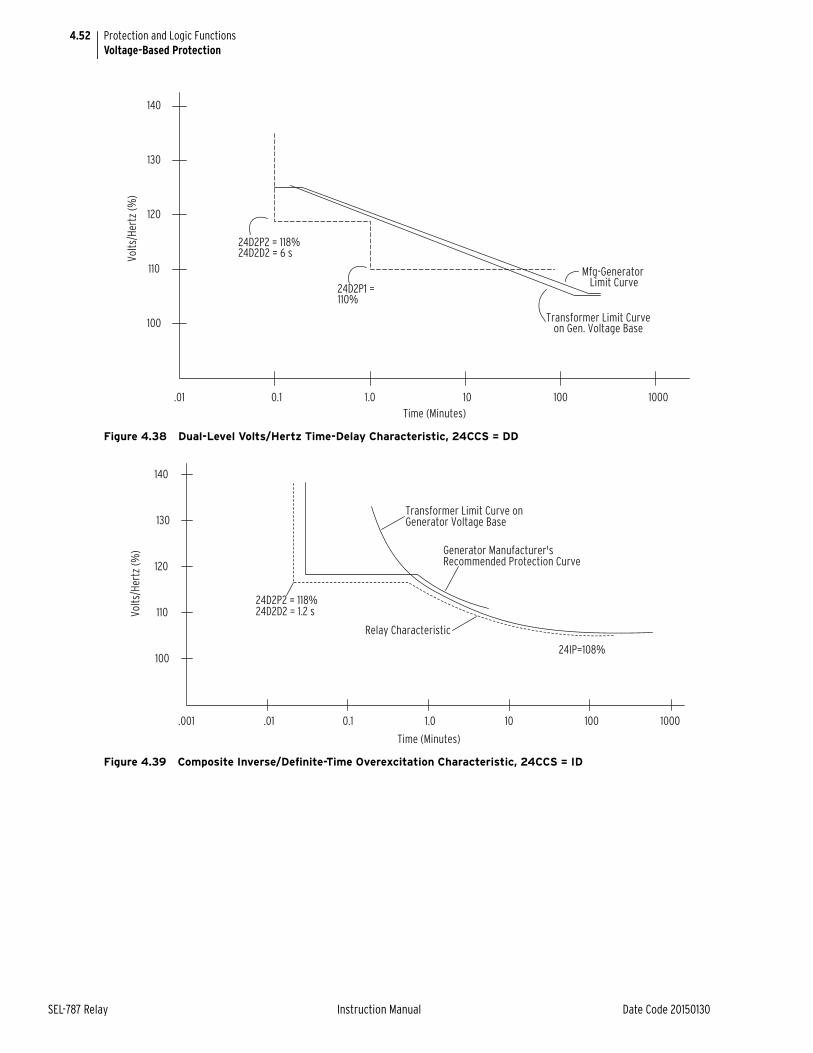
4.52
SEL-787 Relay Instruction Manual Date Code 20150130
Protection and Logic FunctionsVoltage-Based Protection
Figure 4.38 Dual-Level Volts/Hertz Time-Delay Characteristic, 24CCS = DD
Figure 4.39 Composite Inverse/Definite-Time Overexcitation Characteristic, 24CCS = ID
.01 0.1 1.0 10 100 1000
100
110
120
130
140
24D2P2 = 118%24D2D2 = 6 s
24D2P1 = 110%
Time (Minutes)
Transformer Limit Curveon Gen. Voltage Base
Mfg-Generator Limit Curve
Volts
/Her
tz (%
)
Relay Characteristic
Time (Minutes)
Generator Manufacturer's Recommended Protection Curve
Transformer Limit Curve on Generator Voltage Base
.001 .01 0.1 1.0 10 100
100
110
120
130
140
Volts
/Her
tz (%
)
1000
24D2P2 = 118%24D2D2 = 1.2 s
24IP=108%
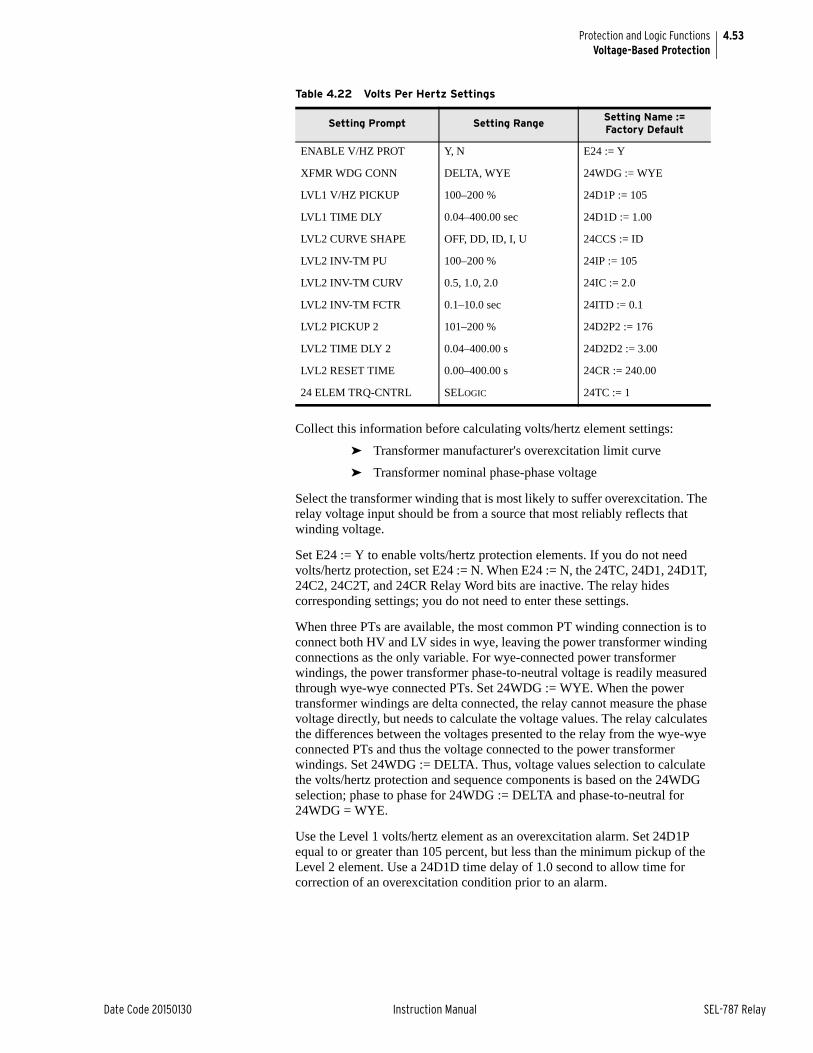
4.53
Date Code 20150130 Instruction Manual SEL-787 Relay
Protection and Logic FunctionsVoltage-Based Protection
Collect this information before calculating volts/hertz element settings:
➤ Transformer manufacturer's overexcitation limit curve
➤ Transformer nominal phase-phase voltage
Select the transformer winding that is most likely to suffer overexcitation. The relay voltage input should be from a source that most reliably reflects that winding voltage.
Set E24 := Y to enable volts/hertz protection elements. If you do not need volts/hertz protection, set E24 := N. When E24 := N, the 24TC, 24D1, 24D1T, 24C2, 24C2T, and 24CR Relay Word bits are inactive. The relay hides corresponding settings; you do not need to enter these settings.
When three PTs are available, the most common PT winding connection is to connect both HV and LV sides in wye, leaving the power transformer winding connections as the only variable. For wye-connected power transformer windings, the power transformer phase-to-neutral voltage is readily measured through wye-wye connected PTs. Set 24WDG := WYE. When the power transformer windings are delta connected, the relay cannot measure the phase voltage directly, but needs to calculate the voltage values. The relay calculates the differences between the voltages presented to the relay from the wye-wye connected PTs and thus the voltage connected to the power transformer windings. Set 24WDG := DELTA. Thus, voltage values selection to calculate the volts/hertz protection and sequence components is based on the 24WDG selection; phase to phase for 24WDG := DELTA and phase-to-neutral for 24WDG = WYE.
Use the Level 1 volts/hertz element as an overexcitation alarm. Set 24D1P equal to or greater than 105 percent, but less than the minimum pickup of the Level 2 element. Use a 24D1D time delay of 1.0 second to allow time for correction of an overexcitation condition prior to an alarm.
Table 4.22 Volts Per Hertz Settings
Setting Prompt Setting RangeSetting Name := Factory Default
ENABLE V/HZ PROT Y, N E24 := Y
XFMR WDG CONN DELTA, WYE 24WDG := WYE
LVL1 V/HZ PICKUP 100–200 % 24D1P := 105
LVL1 TIME DLY 0.04–400.00 sec 24D1D := 1.00
LVL2 CURVE SHAPE OFF, DD, ID, I, U 24CCS := ID
LVL2 INV-TM PU 100–200 % 24IP := 105
LVL2 INV-TM CURV 0.5, 1.0, 2.0 24IC := 2.0
LVL2 INV-TM FCTR 0.1–10.0 sec 24ITD := 0.1
LVL2 PICKUP 2 101–200 % 24D2P2 := 176
LVL2 TIME DLY 2 0.04–400.00 s 24D2D2 := 3.00
LVL2 RESET TIME 0.00–400.00 s 24CR := 240.00
24 ELEM TRQ-CNTRL SELOGIC 24TC := 1
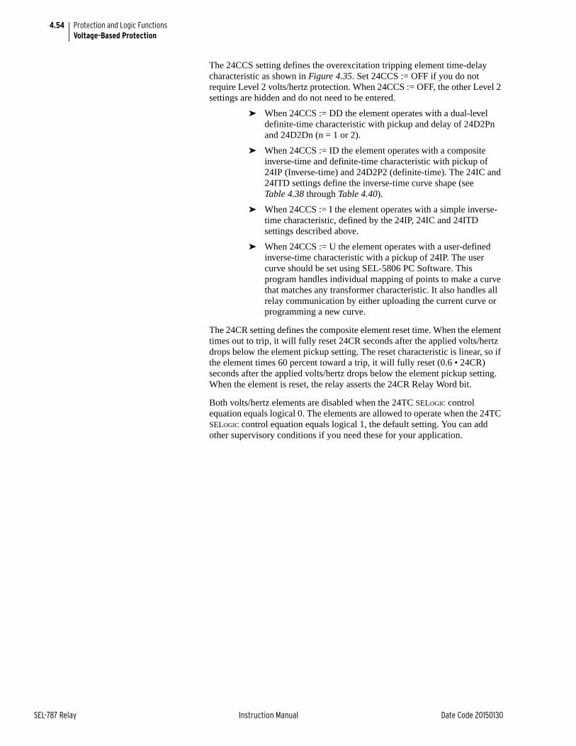
4.54
SEL-787 Relay Instruction Manual Date Code 20150130
Protection and Logic FunctionsVoltage-Based Protection
The 24CCS setting defines the overexcitation tripping element time-delay characteristic as shown in Figure 4.35. Set 24CCS := OFF if you do not require Level 2 volts/hertz protection. When 24CCS := OFF, the other Level 2 settings are hidden and do not need to be entered.
➤ When 24CCS := DD the element operates with a dual-level definite-time characteristic with pickup and delay of 24D2Pn and 24D2Dn (n = 1 or 2).
➤ When 24CCS := ID the element operates with a composite inverse-time and definite-time characteristic with pickup of 24IP (Inverse-time) and 24D2P2 (definite-time). The 24IC and 24ITD settings define the inverse-time curve shape (see Table 4.38 through Table 4.40).
➤ When 24CCS := I the element operates with a simple inverse-time characteristic, defined by the 24IP, 24IC and 24ITD settings described above.
➤ When 24CCS := U the element operates with a user-defined inverse-time characteristic with a pickup of 24IP. The user curve should be set using SEL-5806 PC Software. This program handles individual mapping of points to make a curve that matches any transformer characteristic. It also handles all relay communication by either uploading the current curve or programming a new curve.
The 24CR setting defines the composite element reset time. When the element times out to trip, it will fully reset 24CR seconds after the applied volts/hertz drops below the element pickup setting. The reset characteristic is linear, so if the element times 60 percent toward a trip, it will fully reset (0.6 • 24CR) seconds after the applied volts/hertz drops below the element pickup setting. When the element is reset, the relay asserts the 24CR Relay Word bit.
Both volts/hertz elements are disabled when the 24TC SELOGIC control equation equals logical 0. The elements are allowed to operate when the 24TC SELOGIC control equation equals logical 1, the default setting. You can add other supervisory conditions if you need these for your application.
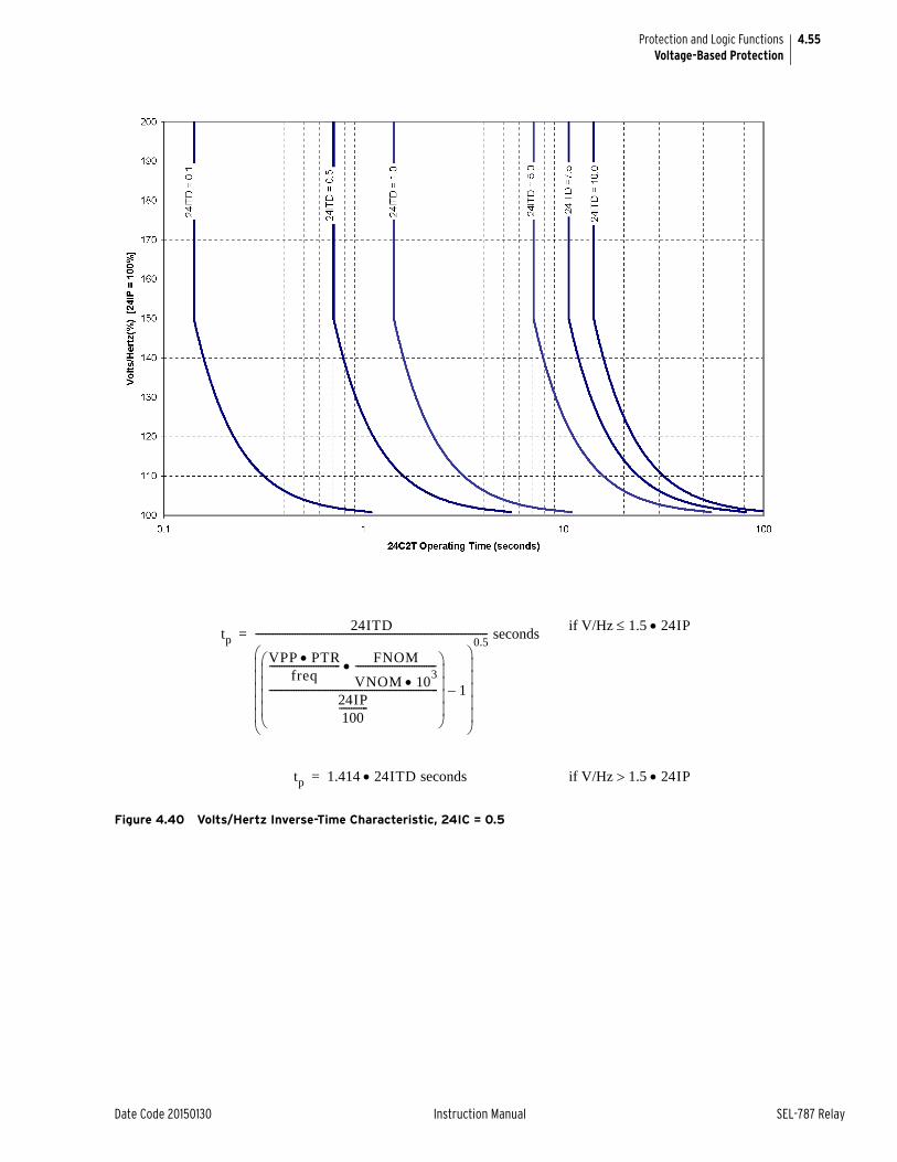
4.55
Date Code 20150130 Instruction Manual SEL-787 Relay
Protection and Logic FunctionsVoltage-Based Protection
Figure 4.40 Volts/Hertz Inverse-Time Characteristic, 24IC = 0.5
tp24ITD
VPP PTRfreq
----------------------------- FNOM
VNOM 103
---------------------------------
24IP100
---------------------------------------------------------------------------------
1–
0.5----------------------------------------------------------------------------------------------- seconds=
if V/Hz 1.5 24IP
tp 1.414 24ITD seconds= if V/Hz 1.5 24IP
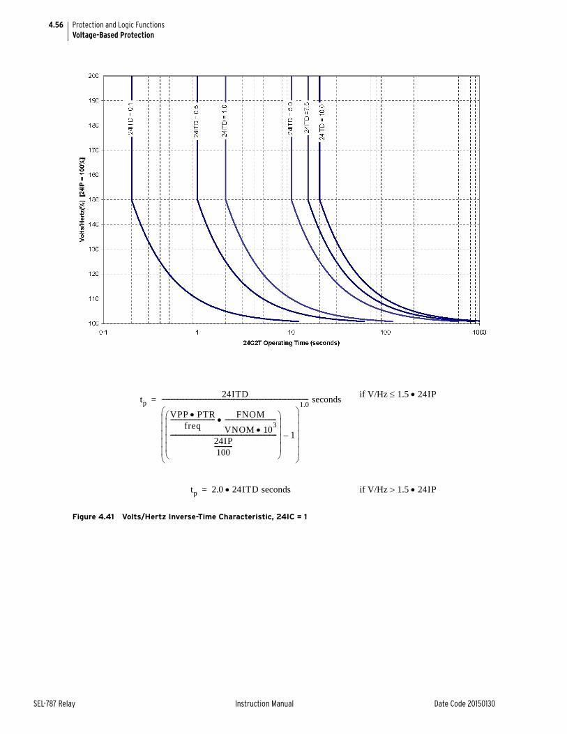
4.56
SEL-787 Relay Instruction Manual Date Code 20150130
Protection and Logic FunctionsVoltage-Based Protection
Figure 4.41 Volts/Hertz Inverse-Time Characteristic, 24IC = 1
tp24ITD
VPP PTRfreq
----------------------------- FNOM
VNOM 103
---------------------------------
24IP100
---------------------------------------------------------------------------------
1–
1.0----------------------------------------------------------------------------------------------- seconds=
if V/Hz 1.5 24IP
tp 2.0 24ITD seconds= if V/Hz 1.5 24IP
4.57
Date Code 20150130 Instruction Manual SEL-787 Relay
Protection and Logic FunctionsVoltage-Based Protection
Figure 4.42 Volts/Hertz Inverse-Time Characteristic, 24IC = 2
tp24ITD
VPP PTRfreq
----------------------------- FNOM
VNOM 103
---------------------------------
24IP100
---------------------------------------------------------------------------------
1–
2.0----------------------------------------------------------------------------------------------- seconds=
if V/Hz 1.5 24IP
tp 4.0 24ITD seconds= if V/Hz 1.5 24IP
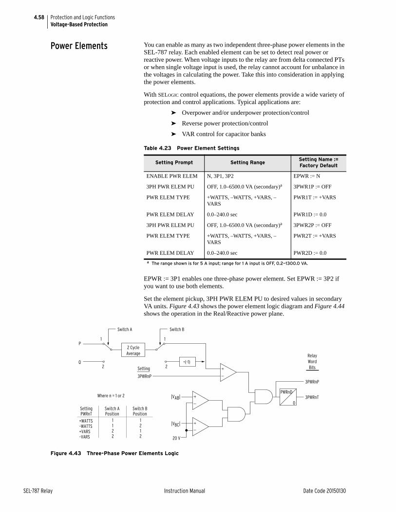
4.58
SEL-787 Relay Instruction Manual Date Code 20150130
Protection and Logic FunctionsVoltage-Based Protection
Power Elements You can enable as many as two independent three-phase power elements in the SEL-787 relay. Each enabled element can be set to detect real power or reactive power. When voltage inputs to the relay are from delta connected PTs or when single voltage input is used, the relay cannot account for unbalance in the voltages in calculating the power. Take this into consideration in applying the power elements.
With SELOGIC control equations, the power elements provide a wide variety of protection and control applications. Typical applications are:
➤ Overpower and/or underpower protection/control
➤ Reverse power protection/control
➤ VAR control for capacitor banks
EPWR := 3P1 enables one three-phase power element. Set EPWR := 3P2 if you want to use both elements.
Set the element pickup, 3PH PWR ELEM PU to desired values in secondary VA units. Figure 4.43 shows the power element logic diagram and Figure 4.44 shows the operation in the Real/Reactive power plane.
Figure 4.43 Three-Phase Power Elements Logic
Table 4.23 Power Element Settings
Setting Prompt Setting RangeSetting Name := Factory Default
ENABLE PWR ELEM N, 3P1, 3P2 EPWR := N
3PH PWR ELEM PU OFF, 1.0–6500.0 VA (secondary)a
a The range shown is for 5 A input; range for 1 A input is OFF, 0.2—1300.0 VA.
3PWR1P := OFF
PWR ELEM TYPE +WATTS, –WATTS, +VARS, –VARS
PWR1T := +VARS
PWR ELEM DELAY 0.0–240.0 sec PWR1D := 0.0
3PH PWR ELEM PU OFF, 1.0–6500.0 VA (secondary)a 3PWR2P := OFF
PWR ELEM TYPE +WATTS, –WATTS, +VARS, –VARS
PWR2T := +VARS
PWR ELEM DELAY 0.0–240.0 sec PWR2D := 0.0
PWRnD
0
3PWRnP
|VAB|
20 V
3PWRnT
RelayWordBits
Switch APosition
+WATTS–WATTS+VARS–VARS
SettingPWRnT
1122
Switch BPosition
1212
Where n = 1 or 2
2 CycleAverage
•(–1)
Switch A Switch B
1 1
2 2
3PWRnP
|VBC|
Setting
P
Q
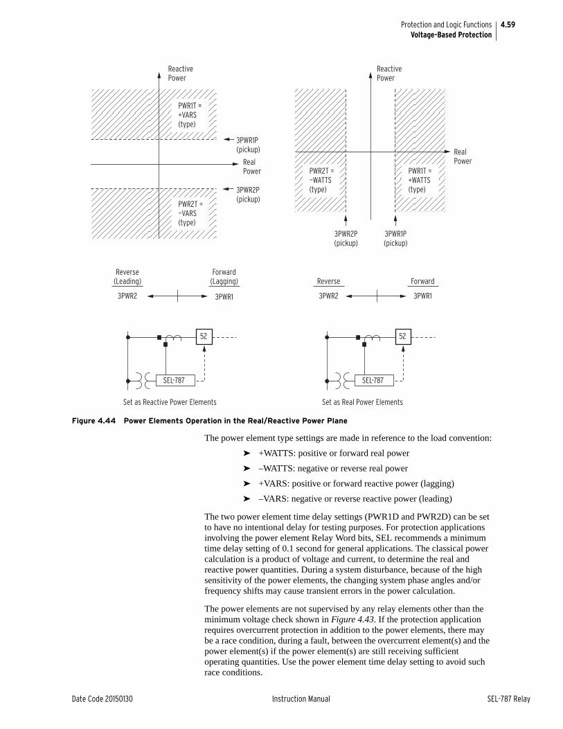
4.59
Date Code 20150130 Instruction Manual SEL-787 Relay
Protection and Logic FunctionsVoltage-Based Protection
Figure 4.44 Power Elements Operation in the Real/Reactive Power Plane
The power element type settings are made in reference to the load convention:
➤ +WATTS: positive or forward real power
➤ –WATTS: negative or reverse real power
➤ +VARS: positive or forward reactive power (lagging)
➤ –VARS: negative or reverse reactive power (leading)
The two power element time delay settings (PWR1D and PWR2D) can be set to have no intentional delay for testing purposes. For protection applications involving the power element Relay Word bits, SEL recommends a minimum time delay setting of 0.1 second for general applications. The classical power calculation is a product of voltage and current, to determine the real and reactive power quantities. During a system disturbance, because of the high sensitivity of the power elements, the changing system phase angles and/or frequency shifts may cause transient errors in the power calculation.
The power elements are not supervised by any relay elements other than the minimum voltage check shown in Figure 4.43. If the protection application requires overcurrent protection in addition to the power elements, there may be a race condition, during a fault, between the overcurrent element(s) and the power element(s) if the power element(s) are still receiving sufficient operating quantities. Use the power element time delay setting to avoid such race conditions.
ReactivePower
ReactivePower
Real Power
Real Power
3PWR2P(pickup)
3PWR1P(pickup)
3PWR1P(pickup)
3PWR2P(pickup)
Set as Reactive Power Elements
Reverse(Leading)
3PWR2 3PWR1 3PWR2 3PWR1
Forward(Lagging)
Set as Real Power Elements
Reverse Forward
SEL-787
52
SEL-787
52
PWR1T = +VARS (type)
PWR2T = —VARS (type)
PWR2T = —WATTS (type)
PWR1T = +WATTS (type)
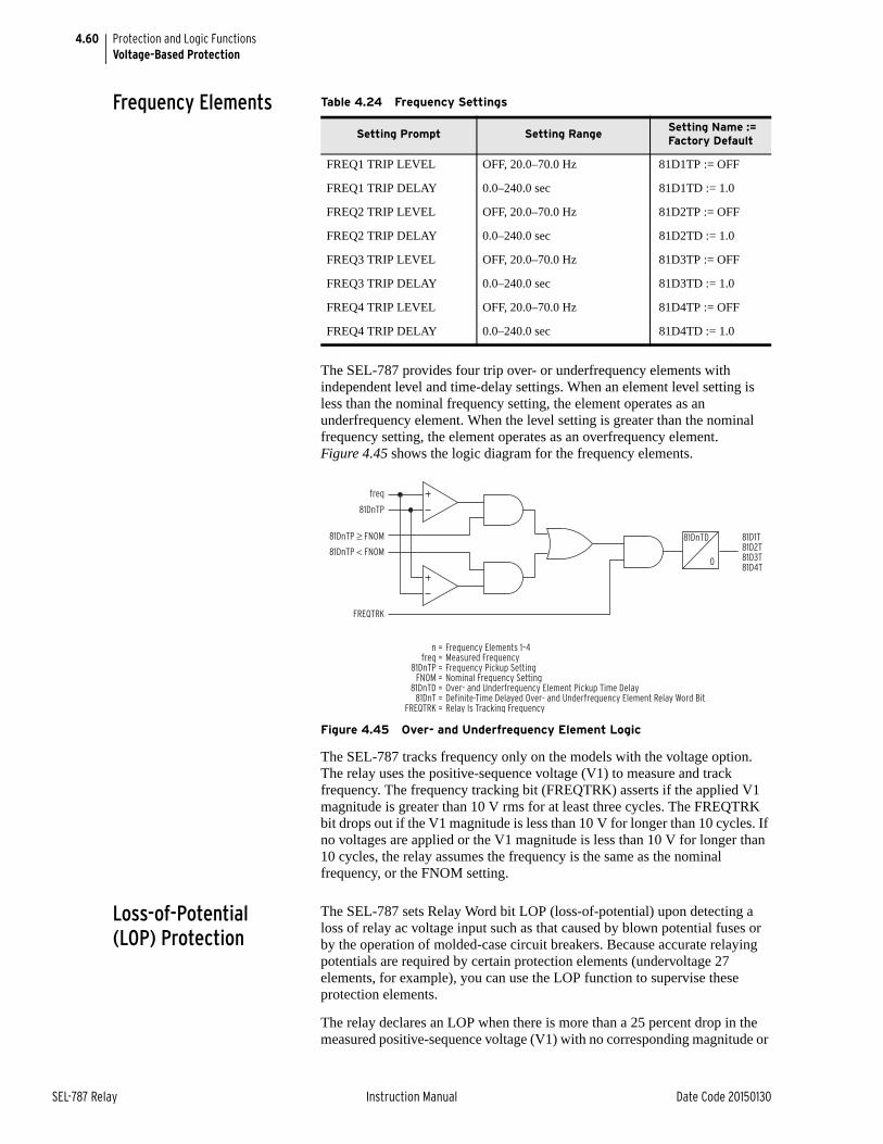
4.60
SEL-787 Relay Instruction Manual Date Code 20150130
Protection and Logic FunctionsVoltage-Based Protection
Frequency Elements
The SEL-787 provides four trip over- or underfrequency elements with independent level and time-delay settings. When an element level setting is less than the nominal frequency setting, the element operates as an underfrequency element. When the level setting is greater than the nominal frequency setting, the element operates as an overfrequency element. Figure 4.45 shows the logic diagram for the frequency elements.
Figure 4.45 Over- and Underfrequency Element Logic
The SEL-787 tracks frequency only on the models with the voltage option. The relay uses the positive-sequence voltage (V1) to measure and track frequency. The frequency tracking bit (FREQTRK) asserts if the applied V1 magnitude is greater than 10 V rms for at least three cycles. The FREQTRK bit drops out if the V1 magnitude is less than 10 V for longer than 10 cycles. If no voltages are applied or the V1 magnitude is less than 10 V for longer than 10 cycles, the relay assumes the frequency is the same as the nominal frequency, or the FNOM setting.
Loss-of-Potential (LOP) Protection
The SEL-787 sets Relay Word bit LOP (loss-of-potential) upon detecting a loss of relay ac voltage input such as that caused by blown potential fuses or by the operation of molded-case circuit breakers. Because accurate relaying potentials are required by certain protection elements (undervoltage 27 elements, for example), you can use the LOP function to supervise these protection elements.
The relay declares an LOP when there is more than a 25 percent drop in the measured positive-sequence voltage (V1) with no corresponding magnitude or
Table 4.24 Frequency Settings
Setting Prompt Setting Range Setting Name := Factory Default
FREQ1 TRIP LEVEL OFF, 20.0–70.0 Hz 81D1TP := OFF
FREQ1 TRIP DELAY 0.0–240.0 sec 81D1TD := 1.0
FREQ2 TRIP LEVEL OFF, 20.0–70.0 Hz 81D2TP := OFF
FREQ2 TRIP DELAY 0.0–240.0 sec 81D2TD := 1.0
FREQ3 TRIP LEVEL OFF, 20.0–70.0 Hz 81D3TP := OFF
FREQ3 TRIP DELAY 0.0–240.0 sec 81D3TD := 1.0
FREQ4 TRIP LEVEL OFF, 20.0–70.0 Hz 81D4TP := OFF
FREQ4 TRIP DELAY 0.0–240.0 sec 81D4TD := 1.0
freq
81DnTP
81D1T81D2T81D3T81D4T
81DnTP < FNOM
81DnTP ≥ FNOM
FREQTRK
81DnTD
0
Frequency Elements 1–4Measured FrequencyFrequency Pickup SettingNominal Frequency SettingOver- and Underfrequency Element Pickup Time DelayDefinite-Time Delayed Over- and Underfrequency Element Relay Word BitRelay Is Tracking Frequency
n =freq =
81DnTP =FNOM =
81DnTD =81DnT =
FREQTRK =
4.61
Date Code 20150130 Instruction Manual SEL-787 Relay
Protection and Logic FunctionsVoltage-Based Protection
angle change (above a pre-determined threshold) in positive-sequence (I1), negative-sequence (I2), or zero-sequence currents (I0).
If this condition persists for 60 cycles, then the relay latches the LOP Relay Word bit at logical 1. The relay resets LOP when the positive-sequence voltage (V1) returns to a level greater than 0.75 • Nominal Voltage while negative-sequence voltage (V2) and zero-sequence voltage (V0) are both less than 5 V secondary.
SettingsThe LOP function has no settings and is always active. You must incorporate the LOP function in a SELOGIC control equation to supervise relay protection elements (see Example 4.3).
LOP Impact on Other Protection ElementsUndervoltage and directional power elements require accurate relaying potentials for correct operation. It is critical that the relay detects an LOP condition and prevents operation of these elements. For example, when dropping a wrench on the phase-voltage input fuse holders, the relay LOP logic accurately determines that this loss of input voltages is an LOP condition and does not trip (if the LOP Relay Word bit supervises selected tripping elements, see Example 4.3). If you are using voltage-determined relay elements for tripping decisions, then blocking these elements is crucial when the voltage component is no longer valid.
EXAMPLE 4.3 Supervising Voltage-Element Tripping With LOP
To supervise undervoltage by LOP one of the trip equations can be set as follows:
TR2:= . . . OR ((27P1T OR 27P2T) AND NOT LOP)
Similarly, if you want the additional voltage-affected elements (e.g., 3PWR1T) to act only when there are correct relaying potentials voltage, use the following in the equation:
. . . OR ((27P1T OR 27P2T OR 3PWR1T) AND NOT LOP)
You can supervise each element separately or as a group when these elements occur in the trip equations, as shown in this example.
LOP Monitoring and AlarmsYou should take steps to immediately correct an LOP problem so that normal protection is rapidly re-established. Include the LOP Relay Word bit in an output contact alarm to notify operation personnel of abnormal voltage input conditions and failures that can be detrimental to the protection system performance if not quickly corrected.
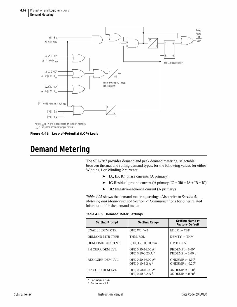
4.62
SEL-787 Relay Instruction Manual Date Code 20150130
Protection and Logic FunctionsDemand Metering
Figure 4.46 Loss-of-Potential (LOP) Logic
Demand MeteringThe SEL-787 provides demand and peak demand metering, selectable between thermal and rolling demand types, for the following values for either Winding 1 or Winding 2 currents:
➤ IA, IB, IC, phase currents (A primary)
➤ IG Residual ground current (A primary; IG = 3I0 = IA + IB + IC)
➤ 3I2 Negative-sequence current (A primary)
Table 4.25 shows the demand metering settings. Also refer to Section 5: Metering and Monitoring and Section 7: Communications for other related information for the demand meter.
60S
R
Q
Q
0
0
60
1
0
LOP| V1 | > 5 V
Δ| V1 | > 25%
Δ | I1 | > 0.1 • INOM
Δ | I2 | > 0.1 • INOM
Δ | I0 | > 0.1 • INOM
| V2 | < 5 V
| V0 | < 5 V
| V1 | > 0.75 • Nominal Voltage
(RESET has priority)
Note: INOM
is 1 A or 5 A depending on the part number.INOM
is the phase secondary input rating.
Timer PU and DO times are in cycles.
Relay Word Bit
Δ I1 > 10°
Δ I2 > 10°
Δ I0 > 10°
Table 4.25 Demand Meter Settings
Setting Prompt Setting Range Setting Name := Factory Default
ENABLE DEM MTR OFF, W1, W2 EDEM := OFF
DEMAND MTR TYPE THM, ROL DEMTY := THM
DEM TIME CONSTNT 5, 10, 15, 30, 60 min DMTC := 5
PH CURR DEM LVL OFF, 0.50-16.00 Aa
OFF. 0.10-3.20 A b
a For Inom = 5 A.b For Inom = 1 A.
PHDEMP := 5.00a
PHDEMP := 1.00 b
RES CURR DEM LVL OFF, 0.50-16.00 Aa
OFF, 0.10-3.2 A bGNDEMP := 1.00a
GNDEMP := 0.20b
3I2 CURR DEM LVL OFF, 0.50-16.00 Aa
OFF, 0.10-3.2 A b3I2DEMP := 1.00a
3I2DEMP := 0.20b
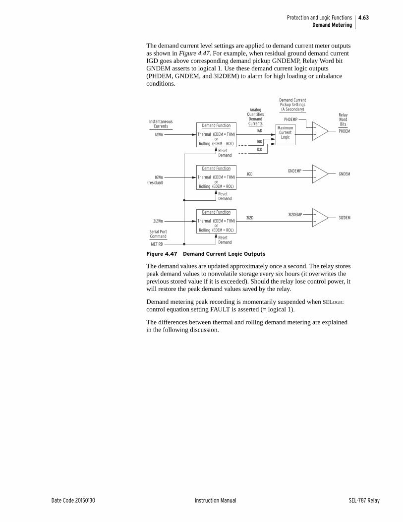
4.63
Date Code 20150130 Instruction Manual SEL-787 Relay
Protection and Logic FunctionsDemand Metering
The demand current level settings are applied to demand current meter outputs as shown in Figure 4.47. For example, when residual ground demand current IGD goes above corresponding demand pickup GNDEMP, Relay Word bit GNDEM asserts to logical 1. Use these demand current logic outputs (PHDEM, GNDEM, and 3I2DEM) to alarm for high loading or unbalance conditions.
Figure 4.47 Demand Current Logic Outputs
The demand values are updated approximately once a second. The relay stores peak demand values to nonvolatile storage every six hours (it overwrites the previous stored value if it is exceeded). Should the relay lose control power, it will restore the peak demand values saved by the relay.
Demand metering peak recording is momentarily suspended when SELOGIC control equation setting FAULT is asserted (= logical 1).
The differences between thermal and rolling demand metering are explained in the following discussion.
PHDEM
RelayWordBits
Demand CurrentPickup Settings(A Secondary)
IBD
IADIAWn
ICD
AnalogQuantitiesDemandCurrentsInstantaneous
Currents
Serial PortCommand
Demand Function Maximum CurrentLogic
Thermal (EDEM = THM)or
Rolling (EDEM = ROL)
Reset Demand
PHDEMP
IGD
Reset Demand
Thermal (EDEM = THM)or
Rolling (EDEM = ROL)
GNDEMGNDEMP
IGWn (residual)
Demand Function
3I2D
Reset Demand
Thermal (EDEM = THM)or
Rolling (EDEM = ROL)
3I2DEM3I2DEMP
3I2Wn
MET RD
Demand Function
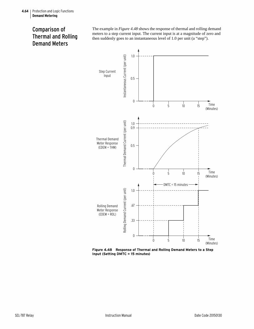
4.64
SEL-787 Relay Instruction Manual Date Code 20150130
Protection and Logic FunctionsDemand Metering
Comparison of Thermal and Rolling Demand Meters
The example in Figure 4.48 shows the response of thermal and rolling demand meters to a step current input. The current input is at a magnitude of zero and then suddenly goes to an instantaneous level of 1.0 per unit (a “step”).
Figure 4.48 Response of Thermal and Rolling Demand Meters to a Step Input (Setting DMTC = 15 minutes)
Thermal Demand Meter Response (EDEM = THM)
Ther
mal
Dem
and
Curr
ent (
per u
nit)
00 5 10 15
0.5
0.91.0
Time(Minutes)
Rolling Demand Meter Response
(EDEM = ROL)
Rolli
ng D
eman
d Cu
rren
t (pe
r uni
t)
DMTC = 15 minutes
00 5 10 15
.33
.67
1.0
Time(Minutes)
Step Current Input
Inst
anta
neou
s Cu
rren
t (pe
r uni
t)
00 5 10 15
0.5
1.0
Time(Minutes)
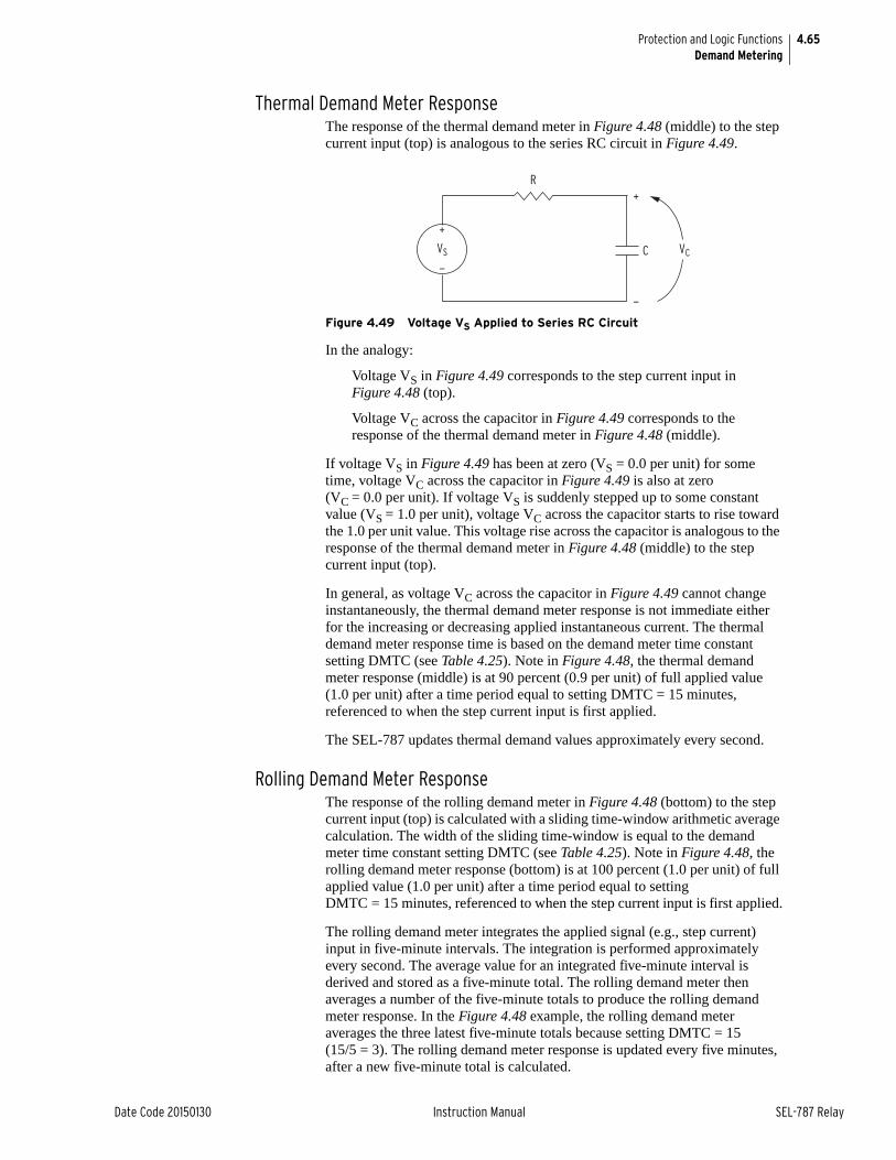
4.65
Date Code 20150130 Instruction Manual SEL-787 Relay
Protection and Logic FunctionsDemand Metering
Thermal Demand Meter ResponseThe response of the thermal demand meter in Figure 4.48 (middle) to the step current input (top) is analogous to the series RC circuit in Figure 4.49.
Figure 4.49 Voltage VS Applied to Series RC Circuit
In the analogy:
Voltage VS in Figure 4.49 corresponds to the step current input in Figure 4.48 (top).
Voltage VC across the capacitor in Figure 4.49 corresponds to the response of the thermal demand meter in Figure 4.48 (middle).
If voltage VS in Figure 4.49 has been at zero (VS = 0.0 per unit) for some time, voltage VC across the capacitor in Figure 4.49 is also at zero (VC = 0.0 per unit). If voltage VS is suddenly stepped up to some constant value (VS = 1.0 per unit), voltage VC across the capacitor starts to rise toward the 1.0 per unit value. This voltage rise across the capacitor is analogous to the response of the thermal demand meter in Figure 4.48 (middle) to the step current input (top).
In general, as voltage VC across the capacitor in Figure 4.49 cannot change instantaneously, the thermal demand meter response is not immediate either for the increasing or decreasing applied instantaneous current. The thermal demand meter response time is based on the demand meter time constant setting DMTC (see Table 4.25). Note in Figure 4.48, the thermal demand meter response (middle) is at 90 percent (0.9 per unit) of full applied value (1.0 per unit) after a time period equal to setting DMTC = 15 minutes, referenced to when the step current input is first applied.
The SEL-787 updates thermal demand values approximately every second.
Rolling Demand Meter ResponseThe response of the rolling demand meter in Figure 4.48 (bottom) to the step current input (top) is calculated with a sliding time-window arithmetic average calculation. The width of the sliding time-window is equal to the demand meter time constant setting DMTC (see Table 4.25). Note in Figure 4.48, the rolling demand meter response (bottom) is at 100 percent (1.0 per unit) of full applied value (1.0 per unit) after a time period equal to setting DMTC = 15 minutes, referenced to when the step current input is first applied.
The rolling demand meter integrates the applied signal (e.g., step current) input in five-minute intervals. The integration is performed approximately every second. The average value for an integrated five-minute interval is derived and stored as a five-minute total. The rolling demand meter then averages a number of the five-minute totals to produce the rolling demand meter response. In the Figure 4.48 example, the rolling demand meter averages the three latest five-minute totals because setting DMTC = 15(15/5 = 3). The rolling demand meter response is updated every five minutes, after a new five-minute total is calculated.
VS VC
+
+
—
—
R
C
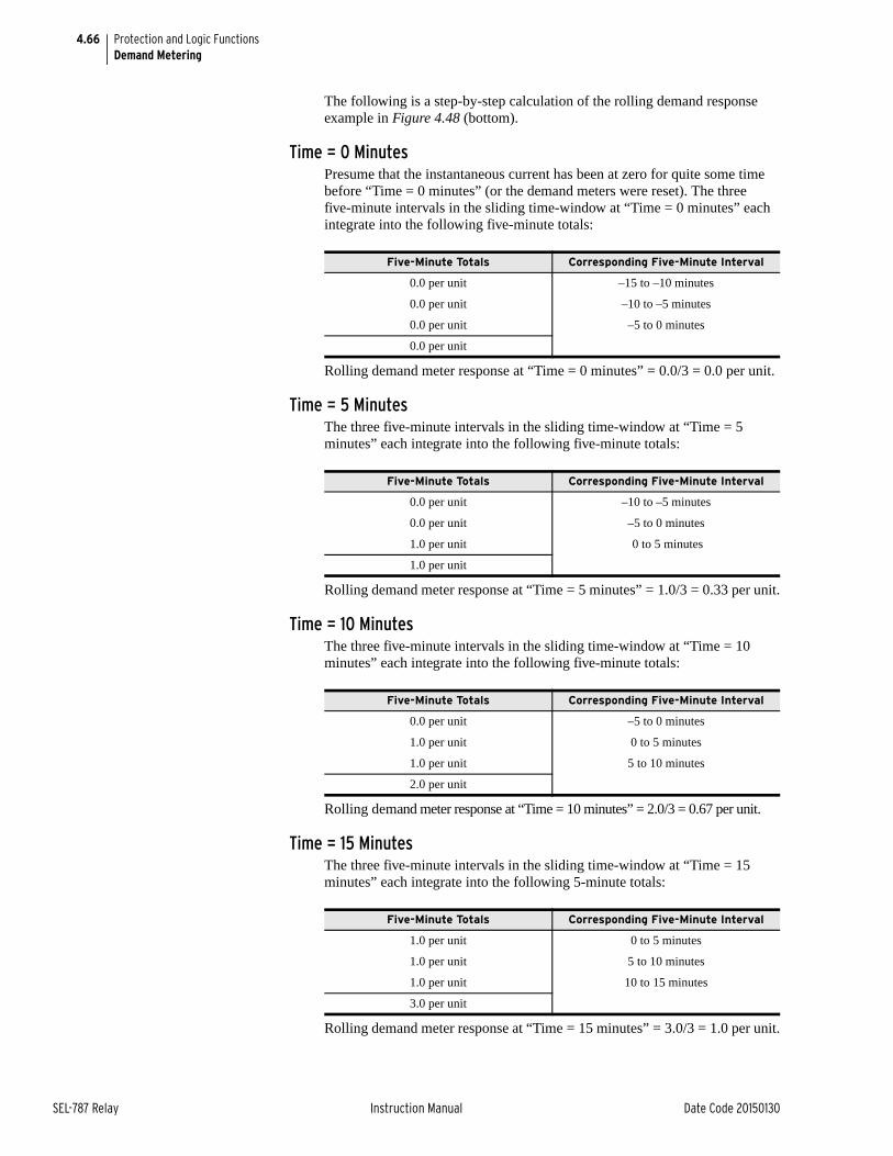
4.66
SEL-787 Relay Instruction Manual Date Code 20150130
Protection and Logic FunctionsDemand Metering
The following is a step-by-step calculation of the rolling demand response example in Figure 4.48 (bottom).
Time = 0 MinutesPresume that the instantaneous current has been at zero for quite some time before “Time = 0 minutes” (or the demand meters were reset). The three five-minute intervals in the sliding time-window at “Time = 0 minutes” each integrate into the following five-minute totals:
Rolling demand meter response at “Time = 0 minutes” = 0.0/3 = 0.0 per unit.
Time = 5 MinutesThe three five-minute intervals in the sliding time-window at “Time = 5 minutes” each integrate into the following five-minute totals:
Rolling demand meter response at “Time = 5 minutes” = 1.0/3 = 0.33 per unit.
Time = 10 MinutesThe three five-minute intervals in the sliding time-window at “Time = 10 minutes” each integrate into the following five-minute totals:
Rolling demand meter response at “Time = 10 minutes” = 2.0/3 = 0.67 per unit.
Time = 15 MinutesThe three five-minute intervals in the sliding time-window at “Time = 15 minutes” each integrate into the following 5-minute totals:
Rolling demand meter response at “Time = 15 minutes” = 3.0/3 = 1.0 per unit.
Five-Minute Totals Corresponding Five-Minute Interval
0.0 per unit –15 to –10 minutes
0.0 per unit –10 to –5 minutes
0.0 per unit –5 to 0 minutes
0.0 per unit
Five-Minute Totals Corresponding Five-Minute Interval
0.0 per unit –10 to –5 minutes
0.0 per unit –5 to 0 minutes
1.0 per unit 0 to 5 minutes
1.0 per unit
Five-Minute Totals Corresponding Five-Minute Interval
0.0 per unit –5 to 0 minutes
1.0 per unit 0 to 5 minutes
1.0 per unit 5 to 10 minutes
2.0 per unit
Five-Minute Totals Corresponding Five-Minute Interval
1.0 per unit 0 to 5 minutes
1.0 per unit 5 to 10 minutes
1.0 per unit 10 to 15 minutes
3.0 per unit
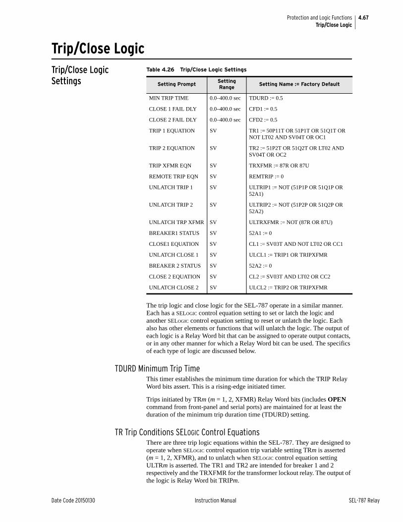
4.67
Date Code 20150130 Instruction Manual SEL-787 Relay
Protection and Logic FunctionsTrip/Close Logic
Trip/Close LogicTrip/Close Logic Settings
The trip logic and close logic for the SEL-787 operate in a similar manner. Each has a SELOGIC control equation setting to set or latch the logic and another SELOGIC control equation setting to reset or unlatch the logic. Each also has other elements or functions that will unlatch the logic. The output of each logic is a Relay Word bit that can be assigned to operate output contacts, or in any other manner for which a Relay Word bit can be used. The specifics of each type of logic are discussed below.
TDURD Minimum Trip TimeThis timer establishes the minimum time duration for which the TRIP Relay Word bits assert. This is a rising-edge initiated timer.
Trips initiated by TRm (m = 1, 2, XFMR) Relay Word bits (includes OPEN command from front-panel and serial ports) are maintained for at least the duration of the minimum trip duration time (TDURD) setting.
TR Trip Conditions SELOGIC Control EquationsThere are three trip logic equations within the SEL-787. They are designed to operate when SELOGIC control equation trip variable setting TRm is asserted (m = 1, 2, XFMR), and to unlatch when SELOGIC control equation setting ULTRm is asserted. The TR1 and TR2 are intended for breaker 1 and 2 respectively and the TRXFMR for the transformer lockout relay. The output of the logic is Relay Word bit TRIPm.
Table 4.26 Trip/Close Logic Settings
Setting PromptSetting Range
Setting Name := Factory Default
MIN TRIP TIME 0.0–400.0 sec TDURD := 0.5
CLOSE 1 FAIL DLY 0.0–400.0 sec CFD1 := 0.5
CLOSE 2 FAIL DLY 0.0–400.0 sec CFD2 := 0.5
TRIP 1 EQUATION SV TR1 := 50P11T OR 51P1T OR 51Q1T OR NOT LT02 AND SV04T OR OC1
TRIP 2 EQUATION SV TR2 := 51P2T OR 51Q2T OR LT02 AND SV04T OR OC2
TRIP XFMR EQN SV TRXFMR := 87R OR 87U
REMOTE TRIP EQN SV REMTRIP := 0
UNLATCH TRIP 1 SV ULTRIP1 := NOT (51P1P OR 51Q1P OR 52A1)
UNLATCH TRIP 2 SV ULTRIP2 := NOT (51P2P OR 51Q2P OR 52A2)
UNLATCH TRP XFMR SV ULTRXFMR := NOT (87R OR 87U)
BREAKER1 STATUS SV 52A1 := 0
CLOSE1 EQUATION SV CL1 := SV03T AND NOT LT02 OR CC1
UNLATCH CLOSE 1 SV ULCL1 := TRIP1 OR TRIPXFMR
BREAKER 2 STATUS SV 52A2 := 0
CLOSE 2 EQUATION SV CL2 := SV03T AND LT02 OR CC2
UNLATCH CLOSE 2 SV ULCL2 := TRIP2 OR TRIPXFMR
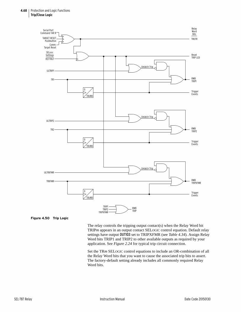
4.68
SEL-787 Relay Instruction Manual Date Code 20150130
Protection and Logic FunctionsTrip/Close Logic
Figure 4.50 Trip Logic
The relay controls the tripping output contact(s) when the Relay Word bit TRIPm appears in an output contact SELOGIC control equation. Default relay settings have output OUT103 set to TRIPXFMR (see Table 4.34). Assign Relay Word bits TRIP1 and TRIP2 to other available outputs as required by your application. See Figure 2.24 for typical trip circuit connection.
Set the TRm SELOGIC control equations to include an OR-combination of all the Relay Word bits that you want to cause the associated trip bits to assert. The factory-default setting already includes all commonly required Relay Word bits.
0
TDURD
Serial PortCommand TAR R
TARGET RESETPushbutton
TRGTR
ResetTRIP LED
RWBTRIP1
TriggerEvents
Unlatch Trip
Comm.Target Reset
RSTTRGT
ULTRIP1
TR1
RelayWordBits
SELOGICSettings
0
TDURD
RWBTRIP2
TriggerEvents
Unlatch Trip
ULTRIP2
TR2
0
TDURD
RWBTRIPXFMR
TriggerEvents
Unlatch Trip
ULTRXFMR
TRXFMR
TRIP1TRIP2
TRIPXFMR
RWBTRIP
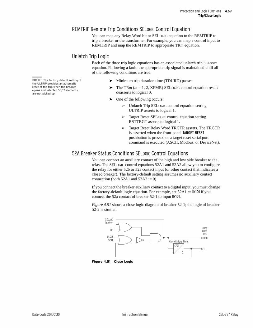
4.69
Date Code 20150130 Instruction Manual SEL-787 Relay
Protection and Logic FunctionsTrip/Close Logic
REMTRIP Remote Trip Conditions SELOGIC Control EquationYou can map any Relay Word bit or SELOGIC equation to the REMTRIP to trip a breaker or the transformer. For example, you can map a control input to REMTRIP and map the REMTRIP to appropriate TRm equation.
Unlatch Trip LogicEach of the three trip logic equations has an associated unlatch trip SELOGIC equation. Following a fault, the appropriate trip signal is maintained until all of the following conditions are true:
NOTE: The factory-default setting of the ULTRIP provides an automatic reset of the trip when the breaker opens and selected 50/51 elements are not picked up.
➤ Minimum trip duration time (TDURD) passes.
➤ The TRm (m = 1, 2, XFMR) SELOGIC control equation result deasserts to logical 0.
➤ One of the following occurs:
➢ Unlatch Trip SELOGIC control equation setting ULTRIP asserts to logical 1.
➢ Target Reset SELOGIC control equation setting RSTTRGT asserts to logical 1.
➢ Target Reset Relay Word TRGTR asserts. The TRGTR is asserted when the front-panel TARGET RESET pushbutton is pressed or a target reset serial port command is executed (ASCII, Modbus, or DeviceNet).
52A Breaker Status Conditions SELOGIC Control EquationsYou can connect an auxiliary contact of the high and low side breaker to the relay. The SELOGIC control equations 52A1 and 52A2 allow you to configure the relay for either 52b or 52a contact input (or other contact that indicates a closed breaker). The factory-default setting assumes no auxiliary contact connection (both 52A1 and 52A2 := 0).
If you connect the breaker auxiliary contact to a digital input, you must change the factory-default logic equation. For example, set 52A1 := IN101 if you connect the 52a contact of breaker 52-1 to input IN101.
Figure 4.51 shows a close logic diagram of breaker 52-1; the logic of breaker 52-2 is similar.
Figure 4.51 Close Logic
CFD1
0
CL1
ULCL1 CLOSE1
CF1
Close Failure Timer
SELOGICEquations
52A1
RelayWordBits
4.70
SEL-787 Relay Instruction Manual Date Code 20150130
Protection and Logic FunctionsLogic Settings (SET L Command)
CL Close SELOGIC Control EquationThere are two close logic equations within the SEL-787. They are designed to operate when SELOGIC control equation close variable setting CLm is asserted (m = 1, 2) and to unlatch when SELOGIC control equation setting ULCLm is asserted. The output of the logic is Relay Word bits CLOSEm.
The relay controls the closing output contact(s) when the Relay Word bit CLOSEm appears in an output contact SELOGIC control equation. Assign the CLOSE bits to desired output relays as required by your application. See Figure 2.20 for typical close circuit connection.
Set the CLm SELOGIC control equations to include an OR-combination of all Relay Word bits that you want to cause the associated close bits to assert. The factory-default setting already includes all commonly required Relay Word bits.
Unlatch Close LogicEach of the two close logic equations has an associated unlatch close SELOGIC equation. Once a CLOSE bit is asserted it is sealed-in until all of the following conditions are true:
➤ Unlatch Close SELOGIC control equation setting ULCL1 (or ULCL2) asserts to logical 1.
➤ Relay Word 52A1 (or 52A2) asserts to logical 1.
➤ Close failure Relay Word bit asserts to logical 1.
Close Failure LogicEach of the two close logic equations includes a close failure detection with an associated delay setting (CFD1 and CFD2). Set the close failure delay equal to the longest close time of the breaker plus a safety margin. If the breaker fails to close, the Relay Word CF1 (or CF2) will assert for 1/4 cycle. Use the CF bits as desired.
Logic Settings (SET L Command)Settings associated with latches, timers, counters, math variables, and output contacts are listed below. Note that SELOGIC equations are processed every quarter cycle while math variable equations and analog quantities are updated every 100 ms.
SELOGIC Enables Table 4.27 shows the enable settings for latch bits (ELAT), SELOGIC control equations (including timers) (ESV), Counters (ESC), and math variable equations (EMV). This helps limit the number of settings that you need to make. For example, if you need six timers, only enable six timers.
IMPORTANT: Upon relay initial power up or Port 1 setting changes or Logic setting changes, the user may have to wait as long as two minutes before an additional setting change can occur. Note that the relay is functional with protection enabled, as soon as the ENABLED LED comes on (approximately 5—10 seconds from power up).
Table 4.27 Enable Settings
Setting Prompt Setting Range Default Setting
SELOGIC Latches N, 1–32 ELAT := 4
SV/Timers N, 1–32 ESV := 5
SELOGIC Counters N, 1–32 ESC := N
Math Variables N, 1–32 EMV := N
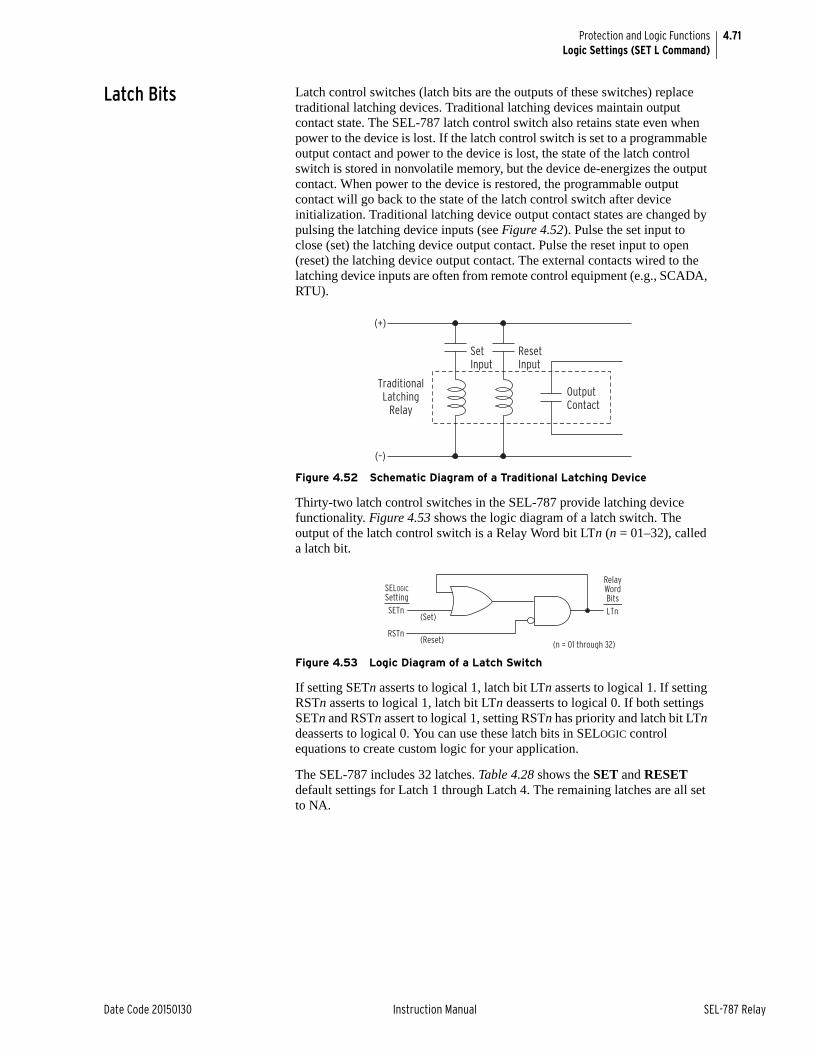
4.71
Date Code 20150130 Instruction Manual SEL-787 Relay
Protection and Logic FunctionsLogic Settings (SET L Command)
Latch Bits Latch control switches (latch bits are the outputs of these switches) replace traditional latching devices. Traditional latching devices maintain output contact state. The SEL-787 latch control switch also retains state even when power to the device is lost. If the latch control switch is set to a programmable output contact and power to the device is lost, the state of the latch control switch is stored in nonvolatile memory, but the device de-energizes the output contact. When power to the device is restored, the programmable output contact will go back to the state of the latch control switch after device initialization. Traditional latching device output contact states are changed by pulsing the latching device inputs (see Figure 4.52). Pulse the set input to close (set) the latching device output contact. Pulse the reset input to open (reset) the latching device output contact. The external contacts wired to the latching device inputs are often from remote control equipment (e.g., SCADA, RTU).
Figure 4.52 Schematic Diagram of a Traditional Latching Device
Thirty-two latch control switches in the SEL-787 provide latching device functionality. Figure 4.53 shows the logic diagram of a latch switch. The output of the latch control switch is a Relay Word bit LTn (n = 01–32), called a latch bit.
Figure 4.53 Logic Diagram of a Latch Switch
If setting SETn asserts to logical 1, latch bit LTn asserts to logical 1. If setting RSTn asserts to logical 1, latch bit LTn deasserts to logical 0. If both settings SETn and RSTn assert to logical 1, setting RSTn has priority and latch bit LTn deasserts to logical 0. You can use these latch bits in SELOGIC control equations to create custom logic for your application.
The SEL-787 includes 32 latches. Table 4.28 shows the SET and RESET default settings for Latch 1 through Latch 4. The remaining latches are all set to NA.
SetInput
ResetInput
OutputContact
TraditionalLatching
Relay
(+)
(–)
LTnSETn
RSTn
(Set)
(Reset) (n = 01 through 32)
RelayWordBits
SELOGICSetting
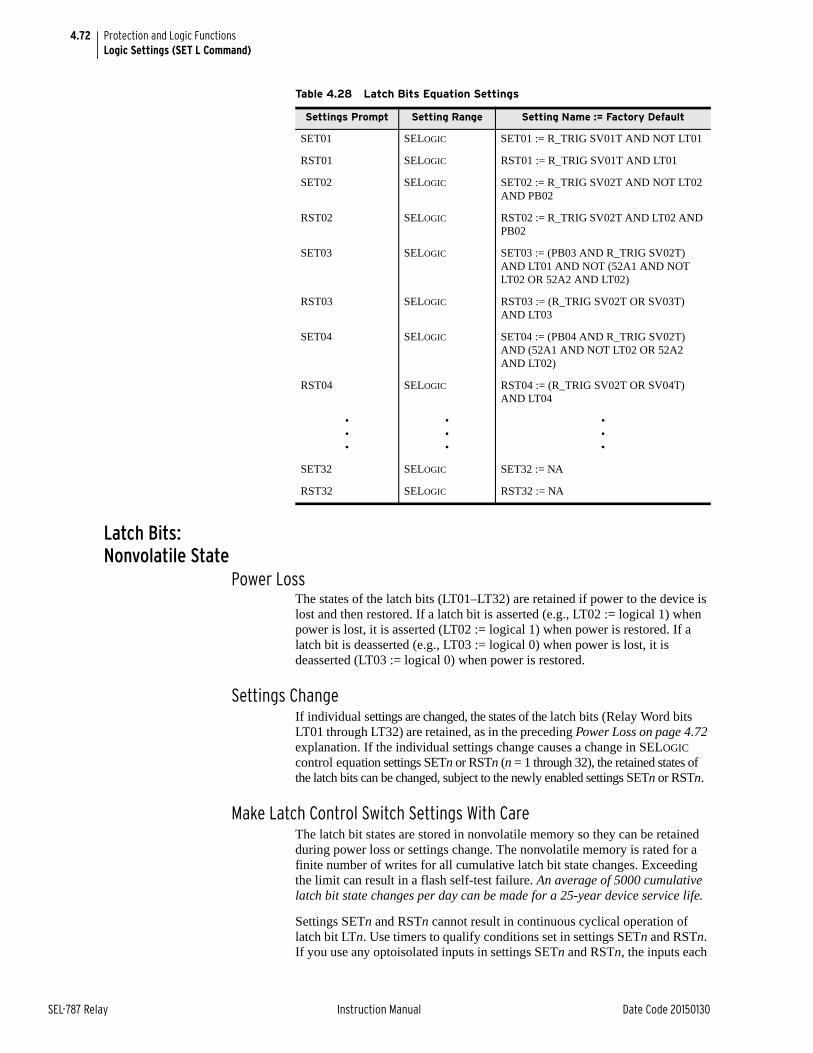
4.72
SEL-787 Relay Instruction Manual Date Code 20150130
Protection and Logic FunctionsLogic Settings (SET L Command)
Latch Bits: Nonvolatile State
Power LossThe states of the latch bits (LT01–LT32) are retained if power to the device is lost and then restored. If a latch bit is asserted (e.g., LT02 := logical 1) when power is lost, it is asserted (LT02 := logical 1) when power is restored. If a latch bit is deasserted (e.g., LT03 := logical 0) when power is lost, it is deasserted (LT03 := logical 0) when power is restored.
Settings ChangeIf individual settings are changed, the states of the latch bits (Relay Word bits LT01 through LT32) are retained, as in the preceding Power Loss on page 4.72 explanation. If the individual settings change causes a change in SELOGIC control equation settings SETn or RSTn (n = 1 through 32), the retained states of the latch bits can be changed, subject to the newly enabled settings SETn or RSTn.
Make Latch Control Switch Settings With CareThe latch bit states are stored in nonvolatile memory so they can be retained during power loss or settings change. The nonvolatile memory is rated for a finite number of writes for all cumulative latch bit state changes. Exceeding the limit can result in a flash self-test failure. An average of 5000 cumulative latch bit state changes per day can be made for a 25-year device service life.
Settings SETn and RSTn cannot result in continuous cyclical operation of latch bit LTn. Use timers to qualify conditions set in settings SETn and RSTn. If you use any optoisolated inputs in settings SETn and RSTn, the inputs each
Table 4.28 Latch Bits Equation Settings
Settings Prompt Setting Range Setting Name := Factory Default
SET01 SELOGIC SET01 := R_TRIG SV01T AND NOT LT01
RST01 SELOGIC RST01 := R_TRIG SV01T AND LT01
SET02 SELOGIC SET02 := R_TRIG SV02T AND NOT LT02 AND PB02
RST02 SELOGIC RST02 := R_TRIG SV02T AND LT02 AND PB02
SET03 SELOGIC SET03 := (PB03 AND R_TRIG SV02T) AND LT01 AND NOT (52A1 AND NOT LT02 OR 52A2 AND LT02)
RST03 SELOGIC RST03 := (R_TRIG SV02T OR SV03T) AND LT03
SET04 SELOGIC SET04 := (PB04 AND R_TRIG SV02T) AND (52A1 AND NOT LT02 OR 52A2 AND LT02)
RST04 SELOGIC RST04 := (R_TRIG SV02T OR SV04T) AND LT04
•••
•••
•••
SET32 SELOGIC SET32 := NA
RST32 SELOGIC RST32 := NA
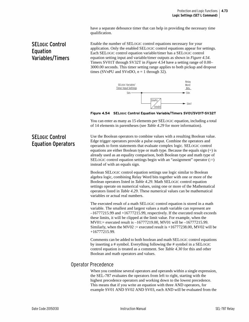
4.73
Date Code 20150130 Instruction Manual SEL-787 Relay
Protection and Logic FunctionsLogic Settings (SET L Command)
have a separate debounce timer that can help in providing the necessary time qualification.
SELOGIC Control Equation Variables/Timers
Enable the number of SELOGIC control equations necessary for your application. Only the enabled SELOGIC control equations appear for settings. Each SELOGIC control equation variable/timer has a SELOGIC control equation setting input and variable/timer outputs as shown in Figure 4.54. Timers SV01T through SV32T in Figure 4.54 have a setting range of 0.00–3000.00 seconds. This timer setting range applies to both pickup and dropout times (SVnPU and SVnDO, n = 1 through 32).
Figure 4.54 SELOGIC Control Equation Variable/Timers SV01/SV01T–SV32T
You can enter as many as 15 elements per SELOGIC equation, including a total of 14 elements in parentheses (see Table 4.29 for more information).
SELOGIC Control Equation Operators
Use the Boolean operators to combine values with a resulting Boolean value. Edge trigger operators provide a pulse output. Combine the operators and operands to form statements that evaluate complex logic. SELOGIC control equations are either Boolean type or math type. Because the equals sign (=) is already used as an equality comparison, both Boolean type and math type of SELOGIC control equation settings begin with an “assignment” operator (:=) instead of with an equals sign.
Boolean SELOGIC control equation settings use logic similar to Boolean algebra logic, combining Relay Word bits together with one or more of the Boolean operators listed in Table 4.29. Math SELOGIC control equation settings operate on numerical values, using one or more of the Mathematical operators listed in Table 4.29. These numerical values can be mathematical variables or actual real numbers.
The executed result of a math SELOGIC control equation is stored in a math variable. The smallest and largest values a math variable can represent are –16777215.99 and +16777215.99, respectively. If the executed result exceeds these limits, it will be clipped at the limit value. For example, when the MV01:= executed result is –16777219.00, MV01 will be –16777215.99. Similarly, when the MV02 := executed result is +16777238.00, MV02 will be +16777215.99.
Comments can be added to both boolean and math SELOGIC control equations by inserting a # symbol. Everything following the # symbol in a SELOGIC control equation is treated as a comment. See Table 4.30 for this and other Boolean and math operators and values.
Operator PrecedenceWhen you combine several operators and operands within a single expression, the SEL-787 evaluates the operators from left to right, starting with the highest precedence operators and working down to the lowest precedence. This means that if you write an equation with three AND operators, for example SV01 AND SV02 AND SV03, each AND will be evaluated from the
SVn SVn
SVnT
SELOGIC Variable/Timer Input Settings
RelayWord Bits
SVnPU
SVnDO
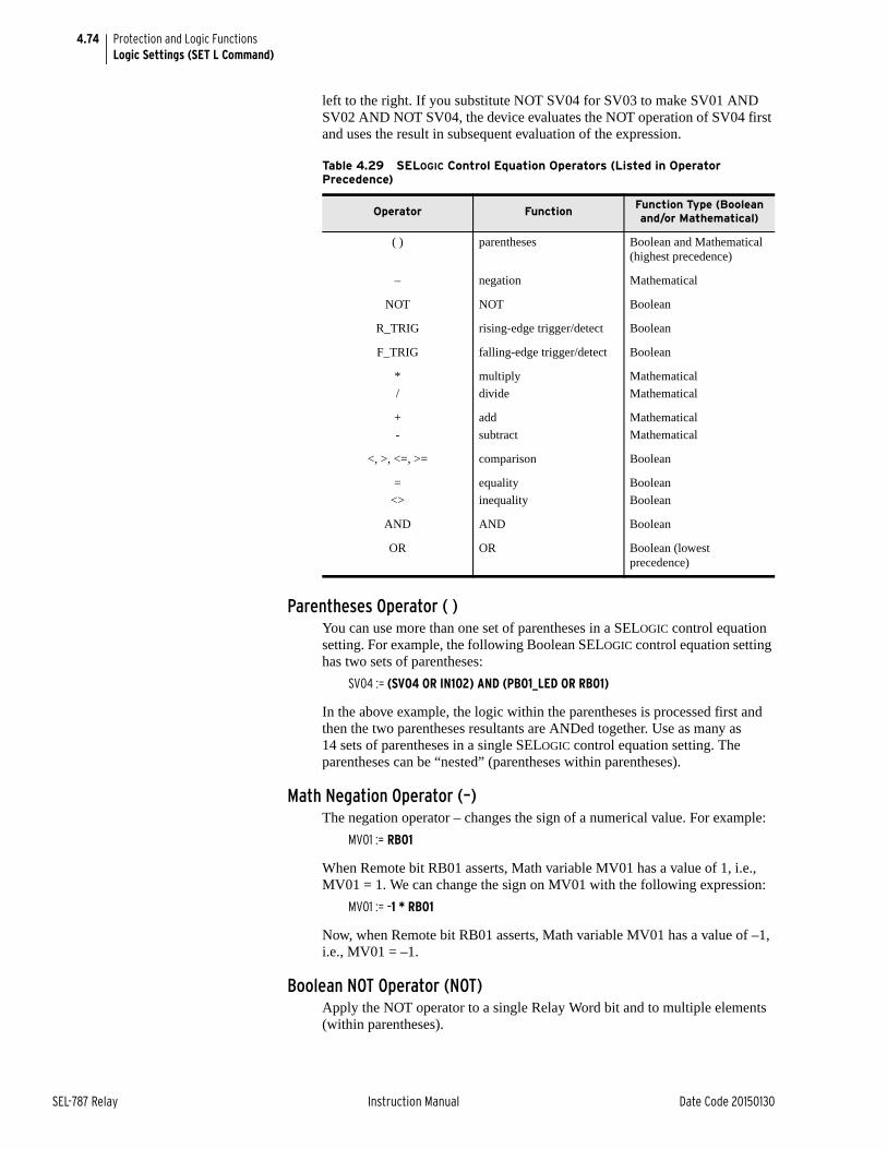
4.74
SEL-787 Relay Instruction Manual Date Code 20150130
Protection and Logic FunctionsLogic Settings (SET L Command)
left to the right. If you substitute NOT SV04 for SV03 to make SV01 AND SV02 AND NOT SV04, the device evaluates the NOT operation of SV04 first and uses the result in subsequent evaluation of the expression.
Parentheses Operator ( )You can use more than one set of parentheses in a SELOGIC control equation setting. For example, the following Boolean SELOGIC control equation setting has two sets of parentheses:
SV04 := (SV04 OR IN102) AND (PB01_LED OR RB01)
In the above example, the logic within the parentheses is processed first and then the two parentheses resultants are ANDed together. Use as many as 14 sets of parentheses in a single SELOGIC control equation setting. The parentheses can be “nested” (parentheses within parentheses).
Math Negation Operator (–)The negation operator – changes the sign of a numerical value. For example:
MV01 := RB01
When Remote bit RB01 asserts, Math variable MV01 has a value of 1, i.e., MV01 = 1. We can change the sign on MV01 with the following expression:
MV01 := –1 * RB01
Now, when Remote bit RB01 asserts, Math variable MV01 has a value of –1, i.e., MV01 = –1.
Boolean NOT Operator (NOT)Apply the NOT operator to a single Relay Word bit and to multiple elements (within parentheses).
Table 4.29 SELOGIC Control Equation Operators (Listed in Operator Precedence)
Operator FunctionFunction Type (Boolean and/or Mathematical)
( ) parentheses Boolean and Mathematical (highest precedence)
– negation Mathematical
NOT NOT Boolean
R_TRIG rising-edge trigger/detect Boolean
F_TRIG falling-edge trigger/detect Boolean
*
/
multiply
divide
Mathematical
Mathematical
+
-
add
subtract
Mathematical
Mathematical
<, >, <=, >= comparison Boolean
=
<>
equality
inequality
Boolean
Boolean
AND AND Boolean
OR OR Boolean (lowest precedence)
4.75
Date Code 20150130 Instruction Manual SEL-787 Relay
Protection and Logic FunctionsLogic Settings (SET L Command)
An example of a single Relay Word bit is as follows:
SV01 := NOT RB01
When Remote bit RB01 asserts from logical 0 to logical 1, the Boolean NOT operator, in turn, changes the logical 1 to a logical 0. In this example, SV01 deasserts when RB01 asserts.
Following is an example of the NOT operator applied to multiple elements within parentheses.
The Boolean SELOGIC control equation OUT101 setting could be set as follows:
OUT101 := NOT(RB01 OR SV02)
If both RB01 and SV02 are deasserted (= logical 0), output contact OUT101 asserts, i.e., OUT101 := NOT (logical 0 OR logical 0) = NOT (logical 0) = logical 1.
In a Math SELOGIC control equation, use the NOT operator with any Relay Word bits. This allows a simple if/else type equation, as shown in the example below.
MV01 := 12 * IN101 + (MV01 + 1) * NOT IN101
The equation above sets MV01 to 12 whenever IN101 asserts, otherwise it increments MV01 by 1 each time the equation is executed.
Boolean Rising-Edge Operator (R_TRIG)Apply the rising-edge operator, R_TRIG, to individual Relay Word bits only; you cannot apply R_TRIG to groups of elements within parentheses. When any Relay Word bit asserts (going from logical 0 to logical 1), R_TRIG interprets this logical 0 to logical 1 transition as a “rising edge” and asserts to logical 1 for one processing interval.
For example, the Boolean SELOGIC control equation event report generation setting uses rising-edge operators:
ER := R_TRIG IN101 OR R_TRIG IN102The rising-edge operators detect a logical 0 to logical 1 transition each time one of IN101 or IN102 asserts. Using these settings, the device triggers a new event report each time IN101 or IN102 asserts anew, if the device is not already recording an event report. You can use the rising-edge operator with the NOT operator as long as the NOT operator precedes the R_TRIG operator. The NOT R_TRIG combination produces a logical 0 for one processing interval when it detects a rising edge on the specified element.
Boolean Falling-Edge Operator (F_TRIG)Apply the falling-edge operator, F_TRIG, to individual Relay Word bits only; you cannot apply F_TRIG to groups of elements within parentheses. The falling-edge operator, F_TRIG, operates similarly to the rising-edge operator, but operates on Relay Word bit deassertion (elements going from logical 1 to logical 0) instead of Relay Word bit assertion. When the Relay Word bit deasserts, F_TRIG interprets this logical 1 to logical 0 transition as a “falling edge” and asserts to logical 1 for one processing interval, as shown in Figure 4.55.
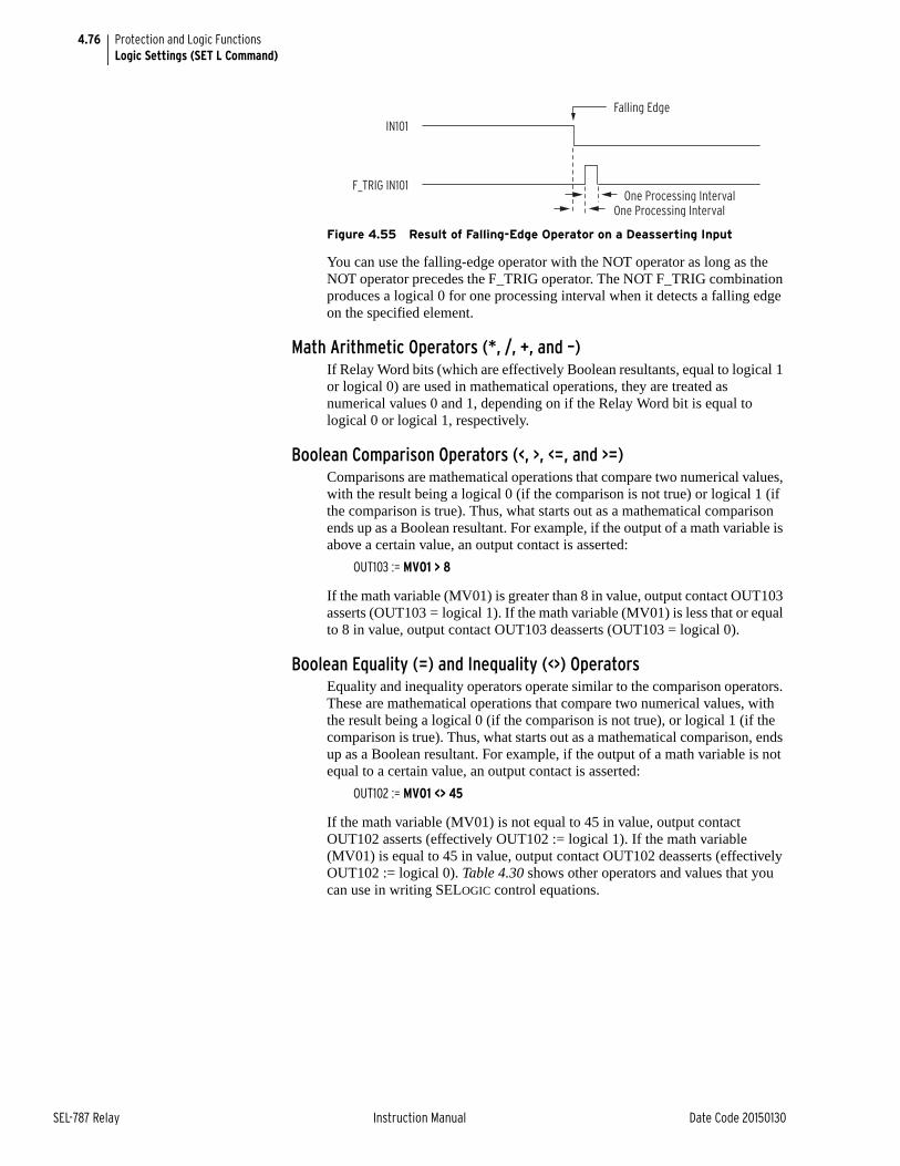
4.76
SEL-787 Relay Instruction Manual Date Code 20150130
Protection and Logic FunctionsLogic Settings (SET L Command)
Figure 4.55 Result of Falling-Edge Operator on a Deasserting Input
You can use the falling-edge operator with the NOT operator as long as the NOT operator precedes the F_TRIG operator. The NOT F_TRIG combination produces a logical 0 for one processing interval when it detects a falling edge on the specified element.
Math Arithmetic Operators (*, /, +, and –)If Relay Word bits (which are effectively Boolean resultants, equal to logical 1 or logical 0) are used in mathematical operations, they are treated as numerical values 0 and 1, depending on if the Relay Word bit is equal to logical 0 or logical 1, respectively.
Boolean Comparison Operators (<, >, <=, and >=)Comparisons are mathematical operations that compare two numerical values, with the result being a logical 0 (if the comparison is not true) or logical 1 (if the comparison is true). Thus, what starts out as a mathematical comparison ends up as a Boolean resultant. For example, if the output of a math variable is above a certain value, an output contact is asserted:
OUT103 := MV01 > 8
If the math variable (MV01) is greater than 8 in value, output contact OUT103 asserts (OUT103 = logical 1). If the math variable (MV01) is less that or equal to 8 in value, output contact OUT103 deasserts (OUT103 = logical 0).
Boolean Equality (=) and Inequality (<>) OperatorsEquality and inequality operators operate similar to the comparison operators. These are mathematical operations that compare two numerical values, with the result being a logical 0 (if the comparison is not true), or logical 1 (if the comparison is true). Thus, what starts out as a mathematical comparison, ends up as a Boolean resultant. For example, if the output of a math variable is not equal to a certain value, an output contact is asserted:
OUT102 := MV01 <> 45
If the math variable (MV01) is not equal to 45 in value, output contact OUT102 asserts (effectively OUT102 := logical 1). If the math variable (MV01) is equal to 45 in value, output contact OUT102 deasserts (effectively OUT102 := logical 0). Table 4.30 shows other operators and values that you can use in writing SELOGIC control equations.
F_TRIG IN101
IN101
Falling Edge
One Processing IntervalOne Processing Interval
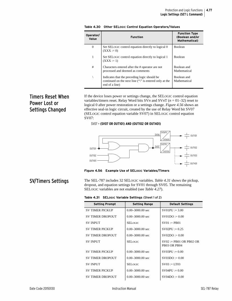
4.77
Date Code 20150130 Instruction Manual SEL-787 Relay
Protection and Logic FunctionsLogic Settings (SET L Command)
Timers Reset When Power Lost or Settings Changed
If the device loses power or settings change, the SELOGIC control equation variables/timers reset. Relay Word bits SVn and SVnT (n = 01–32) reset to logical 0 after power restoration or a settings change. Figure 4.56 shows an effective seal-in logic circuit, created by the use of Relay Word bit SV07 (SELOGIC control equation variable SV07) in SELOGIC control equation SV07:
SV07 = (SV07 OR OUT101) AND (OUT102 OR OUT401)
Figure 4.56 Example Use of SELOGIC Variables/Timers
SV/Timers Settings The SEL-787 includes 32 SELOGIC variables. Table 4.31 shows the pickup, dropout, and equation settings for SV01 through SV05. The remaining SELOGIC variables are not enabled (see Table 4.27).
Table 4.30 Other SELOGIC Control Equation Operators/Values
Operator/Value
FunctionFunction Type
(Boolean and/or Mathematical)
0 Set SELOGIC control equation directly to logical 0 (XXX := 0)
Boolean
1 Set SELOGIC control equation directly to logical 1 (XXX := 1)
Boolean
# Characters entered after the # operator are not processed and deemed as comments
Boolean and Mathematical
\ Indicates that the preceding logic should be continued on the next line (“\” is entered only at the end of a line)
Boolean and Mathematical
SV06PU
SV06D0
SV07PU
SV07D0
SV06
SV07
OUT101
OUT102
OUT103
OUT401
OUT101
OUT102
OUT401
Table 4.31 SELOGIC Variable Settings (Sheet 1 of 2)
Setting Prompt Setting Range Default Settings
SV TIMER PICKUP 0.00–3000.00 sec SV01PU := 3.00
SV TIMER DROPOUT 0.00–3000.00 sec SV01DO := 0.00
SV INPUT SELOGIC SV01 := PB01
SV TIMER PICKUP 0.00–3000.00 sec SV02PU := 0.25
SV TIMER DROPOUT 0.00–3000.00 sec SV02DO := 0.00
SV INPUT SELOGIC SV02 := PB01 OR PB02 OR PB03 OR PB04
SV TIMER PICKUP 0.00–3000.00 sec SV03PU := 0.00
SV TIMER DROPOUT 0.00–3000.00 sec SV03DO := 0.00
SV INPUT SELOGIC SV03 := LT03
SV TIMER PICKUP 0.00–3000.00 sec SV04PU := 0.00
SV TIMER DROPOUT 0.00–3000.00 sec SV04DO := 0.00
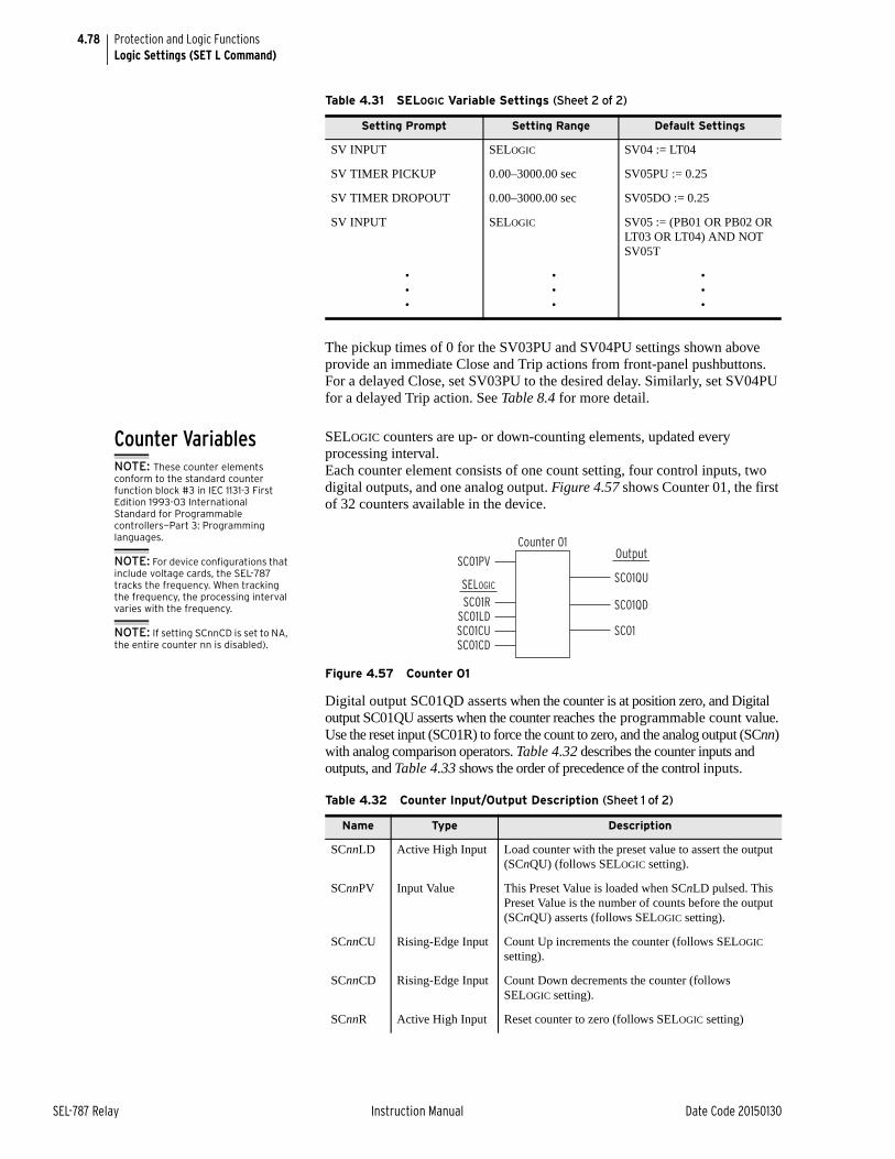
4.78
SEL-787 Relay Instruction Manual Date Code 20150130
Protection and Logic FunctionsLogic Settings (SET L Command)
The pickup times of 0 for the SV03PU and SV04PU settings shown above provide an immediate Close and Trip actions from front-panel pushbuttons. For a delayed Close, set SV03PU to the desired delay. Similarly, set SV04PU for a delayed Trip action. See Table 8.4 for more detail.
Counter Variables SELOGIC counters are up- or down-counting elements, updated every processing interval.Each counter element consists of one count setting, four control inputs, two digital outputs, and one analog output. Figure 4.57 shows Counter 01, the first of 32 counters available in the device.
Figure 4.57 Counter 01
Digital output SC01QD asserts when the counter is at position zero, and Digital output SC01QU asserts when the counter reaches the programmable count value. Use the reset input (SC01R) to force the count to zero, and the analog output (SCnn) with analog comparison operators. Table 4.32 describes the counter inputs and outputs, and Table 4.33 shows the order of precedence of the control inputs.
SV INPUT SELOGIC SV04 := LT04
SV TIMER PICKUP 0.00–3000.00 sec SV05PU := 0.25
SV TIMER DROPOUT 0.00–3000.00 sec SV05DO := 0.25
SV INPUT SELOGIC SV05 := (PB01 OR PB02 OR LT03 OR LT04) AND NOT SV05T
•••
•••
•••
Table 4.31 SELOGIC Variable Settings (Sheet 2 of 2)
Setting Prompt Setting Range Default Settings
Table 4.32 Counter Input/Output Description (Sheet 1 of 2)
Name Type Description
SCnnLD Active High Input Load counter with the preset value to assert the output (SCnQU) (follows SELOGIC setting).
SCnnPV Input Value This Preset Value is loaded when SCnLD pulsed. This Preset Value is the number of counts before the output (SCnQU) asserts (follows SELOGIC setting).
SCnnCU Rising-Edge Input Count Up increments the counter (follows SELOGIC setting).
SCnnCD Rising-Edge Input Count Down decrements the counter (follows SELOGIC setting).
SCnnR Active High Input Reset counter to zero (follows SELOGIC setting)
NOTE: These counter elements conform to the standard counter function block #3 in IEC 1131-3 First Edition 1993-03 International Standard for Programmable controllers—Part 3: Programming languages.
NOTE: For device configurations that include voltage cards, the SEL-787 tracks the frequency. When tracking the frequency, the processing interval varies with the frequency.
NOTE: If setting SCnnCD is set to NA, the entire counter nn is disabled).
SC01PV
SC01RSC01LDSC01CUSC01CD
Counter 01
SC01QU
SC01QD
SC01
SELOGIC
Output
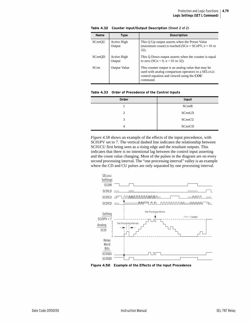
4.79
Date Code 20150130 Instruction Manual SEL-787 Relay
Protection and Logic FunctionsLogic Settings (SET L Command)
Figure 4.58 shows an example of the effects of the input precedence, with SC01PV set to 7. The vertical dashed line indicates the relationship between SC01CU first being seen as a rising edge and the resultant outputs. This indicates that there is no intentional lag between the control input asserting and the count value changing. Most of the pulses in the diagram are on every second processing interval. The “one processing interval” valley is an example where the CD and CU pulses are only separated by one processing interval.
Figure 4.58 Example of the Effects of the Input Precedence
SCnnQU Active High Output
This Q Up output asserts when the Preset Value (maximum count) is reached (SCn = SCnPV, n = 01 to 32).
SCnnQD Active High Output
This Q Down output asserts when the counter is equal to zero (SCn = 0, n = 01 to 32).
SCnn Output Value This counter output is an analog value that may be used with analog comparison operators in a SELOGIC control equation and viewed using the COU command.
Table 4.33 Order of Precedence of the Control Inputs
Order Input
1 SCnnR
2 SCnnLD
3 SCnnCU
4 SCnnCD
Table 4.32 Counter Input/Output Description (Sheet 2 of 2)
Name Type Description
SC01QUSC01QD
RelayWordBits
SC01R
SC01LD
SC01CU
SC01CD
SELOGIC
Settings
SC01PV = 7
Setting
SC01
Analog
= Sample
One Processing Interval
Two Processing Intervals6543210
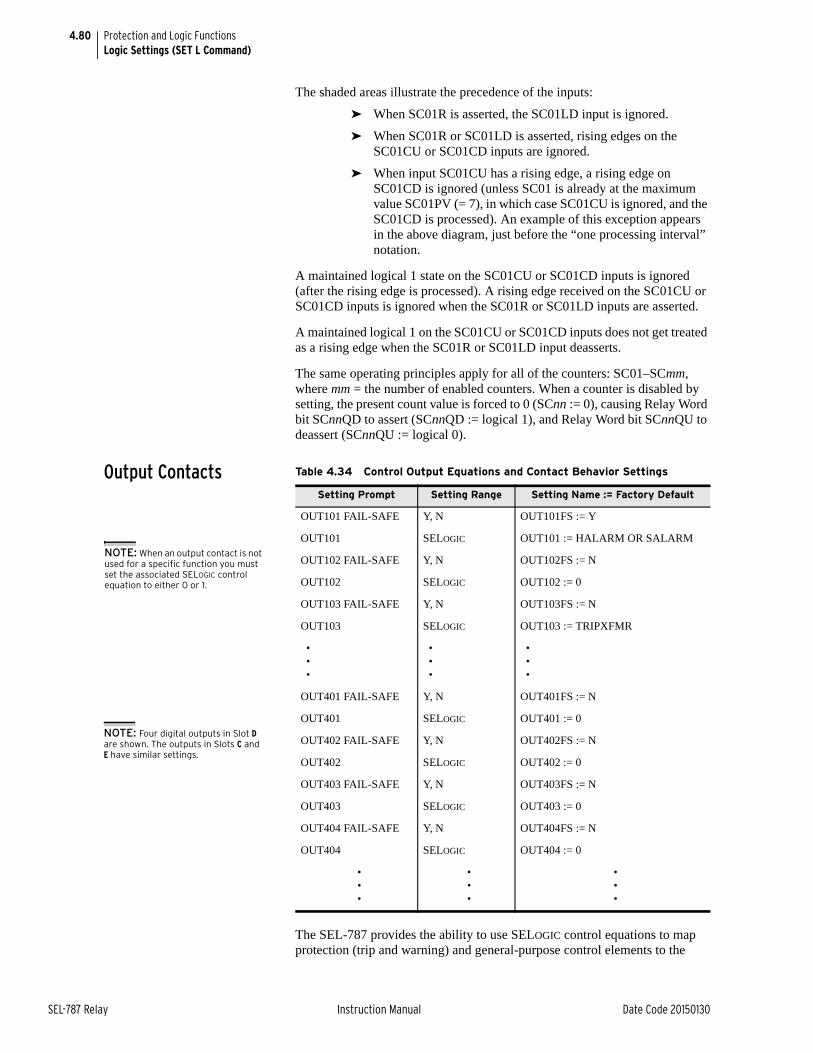
4.80
SEL-787 Relay Instruction Manual Date Code 20150130
Protection and Logic FunctionsLogic Settings (SET L Command)
The shaded areas illustrate the precedence of the inputs:
➤ When SC01R is asserted, the SC01LD input is ignored.
➤ When SC01R or SC01LD is asserted, rising edges on the SC01CU or SC01CD inputs are ignored.
➤ When input SC01CU has a rising edge, a rising edge on SC01CD is ignored (unless SC01 is already at the maximum value SC01PV (= 7), in which case SC01CU is ignored, and the SC01CD is processed). An example of this exception appears in the above diagram, just before the “one processing interval” notation.
A maintained logical 1 state on the SC01CU or SC01CD inputs is ignored (after the rising edge is processed). A rising edge received on the SC01CU or SC01CD inputs is ignored when the SC01R or SC01LD inputs are asserted.
A maintained logical 1 on the SC01CU or SC01CD inputs does not get treated as a rising edge when the SC01R or SC01LD input deasserts.
The same operating principles apply for all of the counters: SC01–SCmm, where mm = the number of enabled counters. When a counter is disabled by setting, the present count value is forced to 0 (SCnn := 0), causing Relay Word bit SCnnQD to assert (SCnnQD := logical 1), and Relay Word bit SCnnQU to deassert (SCnnQU := logical 0).
Output Contacts
The SEL-787 provides the ability to use SELOGIC control equations to map protection (trip and warning) and general-purpose control elements to the
Table 4.34 Control Output Equations and Contact Behavior Settings
Setting Prompt Setting Range Setting Name := Factory Default
OUT101 FAIL-SAFE Y, N OUT101FS := Y
OUT101 SELOGIC OUT101 := HALARM OR SALARM
OUT102 FAIL-SAFE Y, N OUT102FS := N
OUT102 SELOGIC OUT102 := 0
OUT103 FAIL-SAFE Y, N OUT103FS := N
OUT103 SELOGIC OUT103 := TRIPXFMR
•••
•••
•••
OUT401 FAIL-SAFE Y, N OUT401FS := N
OUT401 SELOGIC OUT401 := 0
OUT402 FAIL-SAFE Y, N OUT402FS := N
OUT402 SELOGIC OUT402 := 0
OUT403 FAIL-SAFE Y, N OUT403FS := N
OUT403 SELOGIC OUT403 := 0
OUT404 FAIL-SAFE Y, N OUT404FS := N
OUT404 SELOGIC OUT404 := 0
•••
•••
•••
NOTE: When an output contact is not used for a specific function you must set the associated SELOGIC control equation to either 0 or 1.
NOTE: Four digital outputs in Slot D are shown. The outputs in Slots C and E have similar settings.
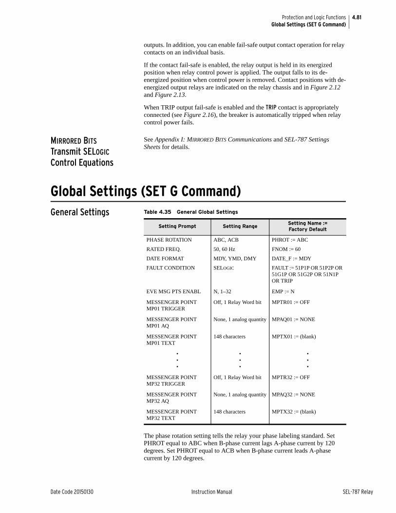
4.81
Date Code 20150130 Instruction Manual SEL-787 Relay
Protection and Logic FunctionsGlobal Settings (SET G Command)
outputs. In addition, you can enable fail-safe output contact operation for relay contacts on an individual basis.
If the contact fail-safe is enabled, the relay output is held in its energized position when relay control power is applied. The output falls to its de-energized position when control power is removed. Contact positions with de-energized output relays are indicated on the relay chassis and in Figure 2.12 and Figure 2.13.
When TRIP output fail-safe is enabled and the TRIP contact is appropriately connected (see Figure 2.16), the breaker is automatically tripped when relay control power fails.
MIRRORED BITS Transmit SELOGIC Control Equations
See Appendix I: MIRRORED BITS Communications and SEL-787 Settings Sheets for details.
Global Settings (SET G Command)General Settings
The phase rotation setting tells the relay your phase labeling standard. Set PHROT equal to ABC when B-phase current lags A-phase current by 120 degrees. Set PHROT equal to ACB when B-phase current leads A-phase current by 120 degrees.
Table 4.35 General Global Settings
Setting Prompt Setting RangeSetting Name :=Factory Default
PHASE ROTATION ABC, ACB PHROT := ABC
RATED FREQ. 50, 60 Hz FNOM := 60
DATE FORMAT MDY, YMD, DMY DATE_F := MDY
FAULT CONDITION SELOGIC FAULT := 51P1P OR 51P2P OR 51G1P OR 51G2P OR 51N1P OR TRIP
EVE MSG PTS ENABL N, 1–32 EMP := N
MESSENGER POINT MP01 TRIGGER
Off, 1 Relay Word bit MPTR01 := OFF
MESSENGER POINT MP01 AQ
None, 1 analog quantity MPAQ01 := NONE
MESSENGER POINT MP01 TEXT
148 characters MPTX01 := (blank)
•••
•••
•••
MESSENGER POINT MP32 TRIGGER
Off, 1 Relay Word bit MPTR32 := OFF
MESSENGER POINT MP32 AQ
None, 1 analog quantity MPAQ32 := NONE
MESSENGER POINT MP32 TEXT
148 characters MPTX32 := (blank)

4.82
SEL-787 Relay Instruction Manual Date Code 20150130
Protection and Logic FunctionsGlobal Settings (SET G Command)
Figure 4.59 Phase Rotation Setting
Set the FNOM setting equal to your system nominal frequency. The DATE_F setting allows you to change the relay date presentation format to the North American standard (Month/Day/Year), the engineering standard (Year/Month/Day), or the European standard (Day/Month/Year).
Set the SELOGIC equation FAULT to temporarily block Maximum and Minimum Metering, Energy Metering, and Demand Metering.
Event Messenger Points
The SEL-787 can be configured to automatically send ASCII message on a communications port when trigger condition is satisfied. Use the SET P command to set PROTO := EVMSG on the desired port to select the port. This feature is designed to send messages to the SEL-3010 Event Messenger, however, any device capable of receiving ASCII messages can be used.
Set EMP to enable the desired number of message points.
Set each of MPTRxx (xx = 01–32) to the desired Relay Word bits, the rising edge of which defines the trigger condition.
MPAQxx is an optional setting and can be used to specify an Analog Quantity to be formatted into a single message as described next.
Use MPTXxx to construct the desired message. Note that by default the analog quantity value, if specified, will be added at the end of the message, rounded to the nearest integer value (see Example 4.4).
EXAMPLE 4.4 Setting MPTXxx Using the Default Location of Analog Quantity
MPTX01 := THE LOAD CURRENT IS
MPAQ01 value = 157.44
Formatted message out when triggered: THE LOAD CURRENT IS 157
Location and resolution of the analog quantity value within the message can be specified by using “%.pf”, where,
% defines location of the value
p defines number of digits (as many as 6, defaults to 6 if omitted)
f indicates floating point value (use %d if nearest whole number is desired)
B
C
A
C
PHROT = ABC
A
PHROT = ACB
B
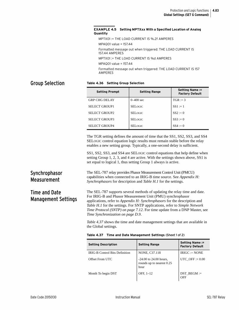
4.83
Date Code 20150130 Instruction Manual SEL-787 Relay
Protection and Logic FunctionsGlobal Settings (SET G Command)
EXAMPLE 4.5 Setting MPTXxx With a Specified Location of Analog Quantity
MPTX01 := THE LOAD CURRENT IS %.2f AMPERES
MPAQ01 value = 157.44
Formatted message out when triggered: THE LOAD CURRENT IS 157.44 AMPERES
MPTX01 := THE LOAD CURRENT IS %d AMPERES
MPAQ01 value = 157.44
Formatted message out when triggered: THE LOAD CURRENT IS 157 AMPERES
Group Selection
The TGR setting defines the amount of time that the SS1, SS2, SS3, and SS4 SELOGIC control equation logic results must remain stable before the relay enables a new setting group. Typically, a one-second delay is sufficient.
SS1, SS2, SS3, and SS4 are SELOGIC control equations that help define when setting Group 1, 2, 3, and 4 are active. With the settings shown above, SS1 is set equal to logical 1, thus setting Group 1 always is active.
Synchrophasor Measurement
The SEL-787 relay provides Phasor Measurement Control Unit (PMCU) capabilities when connected to an IRIG-B time source. See Appendix H: Synchrophasors for description and Table H.1 for the settings.
Time and Date Management Settings
The SEL-787 supports several methods of updating the relay time and date. For IRIG-B and Phasor Measurement Unit (PMU) synchrophasor applications, refer to Appendix H: Synchrophasors for the description and Table H.1 for the settings. For SNTP applications, refer to Simple Network Time Protocol (SNTP) on page 7.12. For time update from a DNP Master, see Time Synchronization on page D.9.
Table 4.37 shows the time and date management settings that are available in the Global settings.
Table 4.36 Setting Group Selection
Setting Prompt Setting RangeSetting Name := Factory Default
GRP CHG DELAY 0–400 sec TGR := 3
SELECT GROUP1 SELOGIC SS1 := 1
SELECT GROUP2 SELOGIC SS2 := 0
SELECT GROUP3 SELOGIC SS3 := 0
SELECT GROUP4 SELOGIC SS4 := 0
Table 4.37 Time and Date Management Settings (Sheet 1 of 2)
Setting Description Setting RangeSetting Name := Factory Default
IRIG-B Control Bits Definition NONE, C37.118 IRIGC := NONE
Offset From UTC -24.00 to 24.00 hours, rounds up to nearest 0.25 hour
UTC_OFF := 0.00
Month To begin DST OFF, 1–12 DST_BEGM := OFF
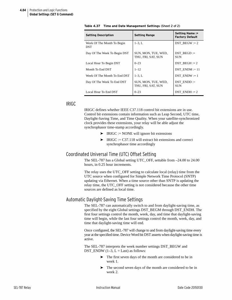
4.84
SEL-787 Relay Instruction Manual Date Code 20150130
Protection and Logic FunctionsGlobal Settings (SET G Command)
IRIGCIRIGC defines whether IEEE C37.118 control bit extensions are in use. Control bit extensions contain information such as Leap Second, UTC time, Daylight-Saving Time, and Time Quality. When your satellite-synchronized clock provides these extensions, your relay will be able adjust the synchrophasor time-stamp accordingly.
➤ IRIGC := NONE will ignore bit extensions
➤ IRIGC := C37.118 will extract bit extensions and correct synchrophasor time accordingly
Coordinated Universal Time (UTC) Offset SettingThe SEL-787 has a Global setting UTC_OFF, settable from –24.00 to 24.00 hours, in 0.25 hour increments.
The relay uses the UTC_OFF setting to calculate local (relay) time from the UTC source when configured for Simple Network Time Protocol (SNTP) updating via Ethernet. When a time source other than SNTP is updating the relay time, the UTC_OFF setting is not considered because the other time sources are defined as local time.
Automatic Daylight-Saving Time SettingsThe SEL-787 can automatically switch to and from daylight-saving time, as specified by the eight Global settings DST_BEGM through DST_ENDH. The first four settings control the month, week, day, and time that daylight-saving time will begin, while the last four settings control the month, week, day, and time that daylight-saving time will end.
Once configured, the SEL-787 will change to and from daylight-saving time every year at the specified time. Device Word bit DST asserts when daylight-saving time is active.
The SEL-787 interprets the week number settings DST_BEGW and DST_ENDW (1–3, L = Last) as follows:
➤ The first seven days of the month are considered to be in week 1.
➤ The second seven days of the month are considered to be in week 2.
Week Of The Month To Begin DST
1–3, L DST_BEGW := 2
Day Of The Week To Begin DST SUN, MON, TUE, WED, THU, FRI, SAT, SUN
DST_BEGD := SUN
Local Hour To Begin DST 0–23 DST_BEGH := 2
Month To End DST 1–12 DST_ENDM := 11
Week Of The Month To End DST 1–3, L DST_ENDW := 1
Day Of The Week To End DST SUN, MON, TUE, WED, THU, FRI, SAT, SUN
DST_ENDD := SUN
Local Hour To End DST 0–23 DST_ENDH := 2
Table 4.37 Time and Date Management Settings (Sheet 2 of 2)
Setting Description Setting RangeSetting Name := Factory Default
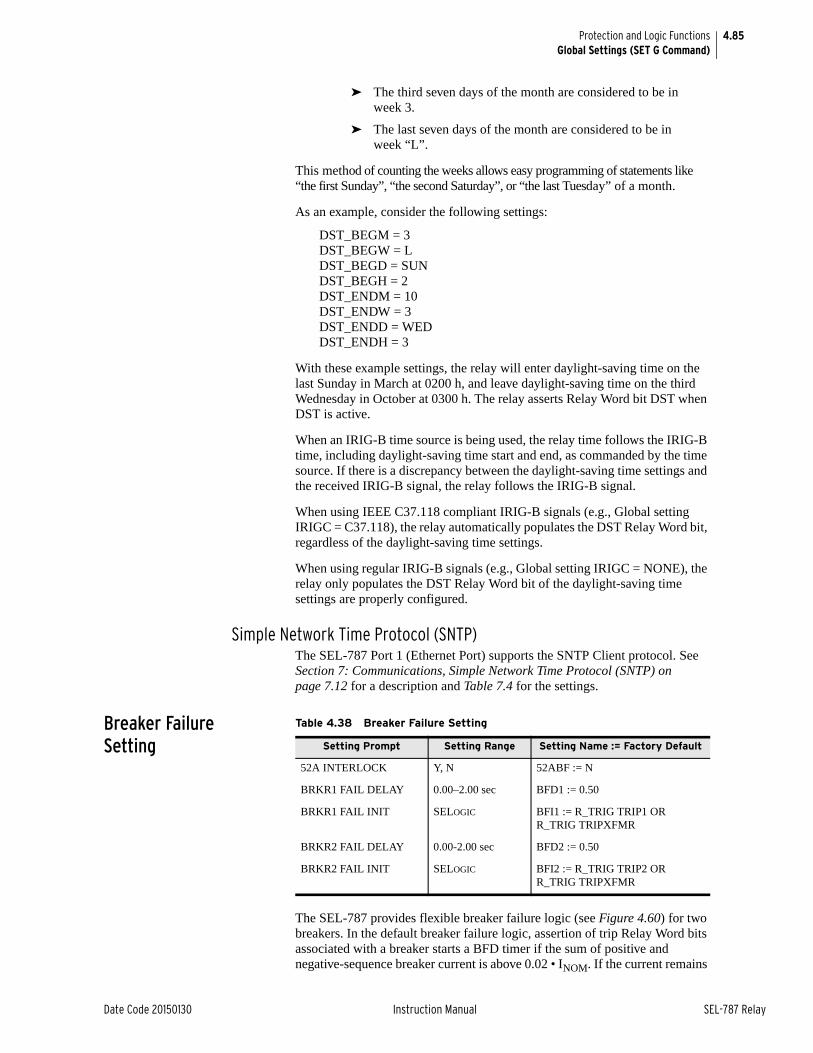
4.85
Date Code 20150130 Instruction Manual SEL-787 Relay
Protection and Logic FunctionsGlobal Settings (SET G Command)
➤ The third seven days of the month are considered to be in week 3.
➤ The last seven days of the month are considered to be in week “L”.
This method of counting the weeks allows easy programming of statements like “the first Sunday”, “the second Saturday”, or “the last Tuesday” of a month.
As an example, consider the following settings:
DST_BEGM = 3DST_BEGW = LDST_BEGD = SUNDST_BEGH = 2DST_ENDM = 10DST_ENDW = 3DST_ENDD = WEDDST_ENDH = 3
With these example settings, the relay will enter daylight-saving time on the last Sunday in March at 0200 h, and leave daylight-saving time on the third Wednesday in October at 0300 h. The relay asserts Relay Word bit DST when DST is active.
When an IRIG-B time source is being used, the relay time follows the IRIG-B time, including daylight-saving time start and end, as commanded by the time source. If there is a discrepancy between the daylight-saving time settings and the received IRIG-B signal, the relay follows the IRIG-B signal.
When using IEEE C37.118 compliant IRIG-B signals (e.g., Global setting IRIGC = C37.118), the relay automatically populates the DST Relay Word bit, regardless of the daylight-saving time settings.
When using regular IRIG-B signals (e.g., Global setting IRIGC = NONE), the relay only populates the DST Relay Word bit of the daylight-saving time settings are properly configured.
Simple Network Time Protocol (SNTP)The SEL-787 Port 1 (Ethernet Port) supports the SNTP Client protocol. See Section 7: Communications, Simple Network Time Protocol (SNTP) on page 7.12 for a description and Table 7.4 for the settings.
Breaker Failure Setting
The SEL-787 provides flexible breaker failure logic (see Figure 4.60) for two breakers. In the default breaker failure logic, assertion of trip Relay Word bits associated with a breaker starts a BFD timer if the sum of positive and negative-sequence breaker current is above 0.02 • INOM. If the current remains
Table 4.38 Breaker Failure Setting
Setting Prompt Setting Range Setting Name := Factory Default
52A INTERLOCK Y, N 52ABF := N
BRKR1 FAIL DELAY 0.00–2.00 sec BFD1 := 0.50
BRKR1 FAIL INIT SELOGIC BFI1 := R_TRIG TRIP1 OR R_TRIG TRIPXFMR
BRKR2 FAIL DELAY 0.00-2.00 sec BFD2 := 0.50
BRKR2 FAIL INIT SELOGIC BFI2 := R_TRIG TRIP2 OR R_TRIG TRIPXFMR
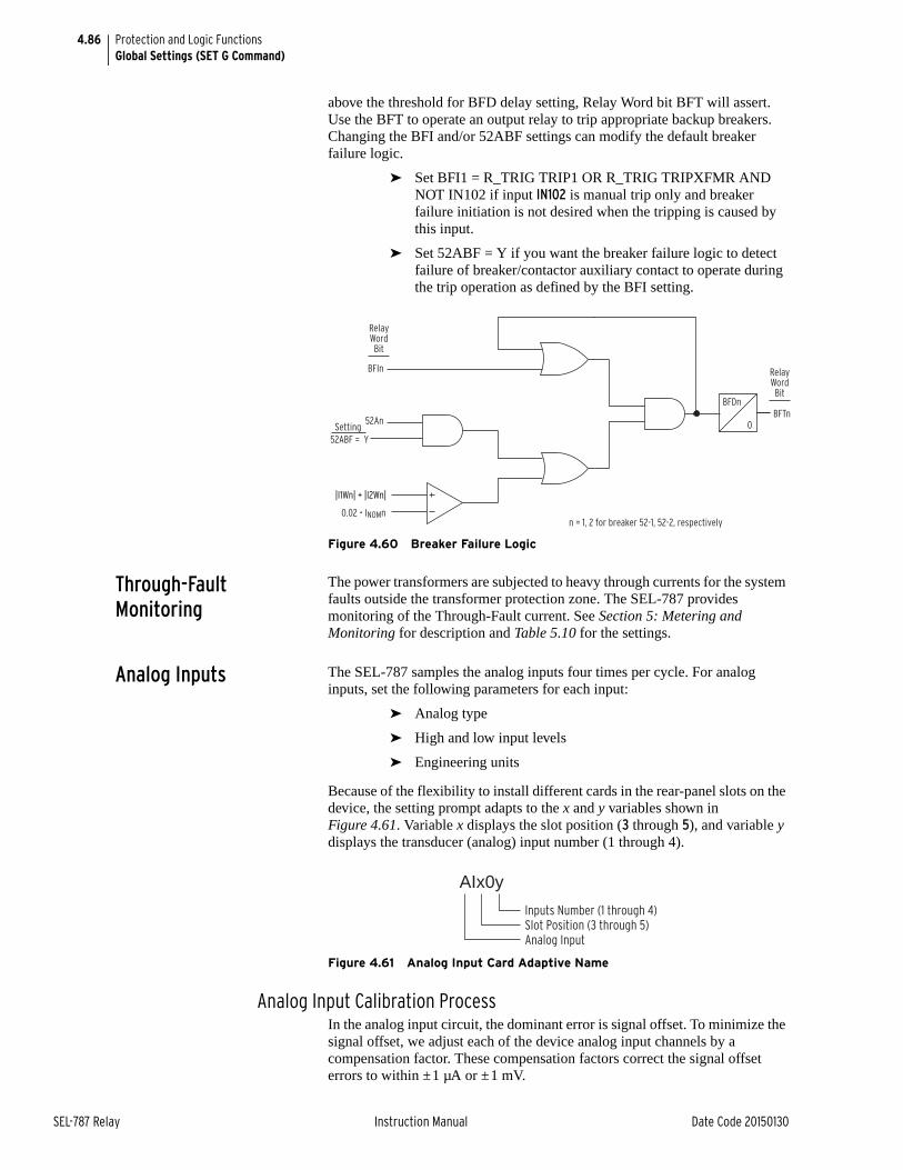
4.86
SEL-787 Relay Instruction Manual Date Code 20150130
Protection and Logic FunctionsGlobal Settings (SET G Command)
above the threshold for BFD delay setting, Relay Word bit BFT will assert. Use the BFT to operate an output relay to trip appropriate backup breakers.Changing the BFI and/or 52ABF settings can modify the default breaker failure logic.
➤ Set BFI1 = R_TRIG TRIP1 OR R_TRIG TRIPXFMR AND NOT IN102 if input IN102 is manual trip only and breaker failure initiation is not desired when the tripping is caused by this input.
➤ Set 52ABF = Y if you want the breaker failure logic to detect failure of breaker/contactor auxiliary contact to operate during the trip operation as defined by the BFI setting.
Figure 4.60 Breaker Failure Logic
Through-Fault Monitoring
The power transformers are subjected to heavy through currents for the system faults outside the transformer protection zone. The SEL-787 provides monitoring of the Through-Fault current. See Section 5: Metering and Monitoring for description and Table 5.10 for the settings.
Analog Inputs The SEL-787 samples the analog inputs four times per cycle. For analog inputs, set the following parameters for each input:
➤ Analog type
➤ High and low input levels
➤ Engineering units
Because of the flexibility to install different cards in the rear-panel slots on the device, the setting prompt adapts to the x and y variables shown in Figure 4.61. Variable x displays the slot position (3 through 5), and variable y displays the transducer (analog) input number (1 through 4).
Figure 4.61 Analog Input Card Adaptive Name
Analog Input Calibration ProcessIn the analog input circuit, the dominant error is signal offset. To minimize the signal offset, we adjust each of the device analog input channels by a compensation factor. These compensation factors correct the signal offset errors to within ±1 µA or ±1 mV.
52ABF = Y
BFIn
Setting52An
0.02 • INOMn
|I1Wn| + |I2Wn|
BFDn
0
RelayWordBit
BFTn
RelayWordBit
n = 1, 2 for breaker 52-1, 52-2, respectively
Inputs Number (1 through 4)Slot Position (3 through 5)Analog Input
AIx0y
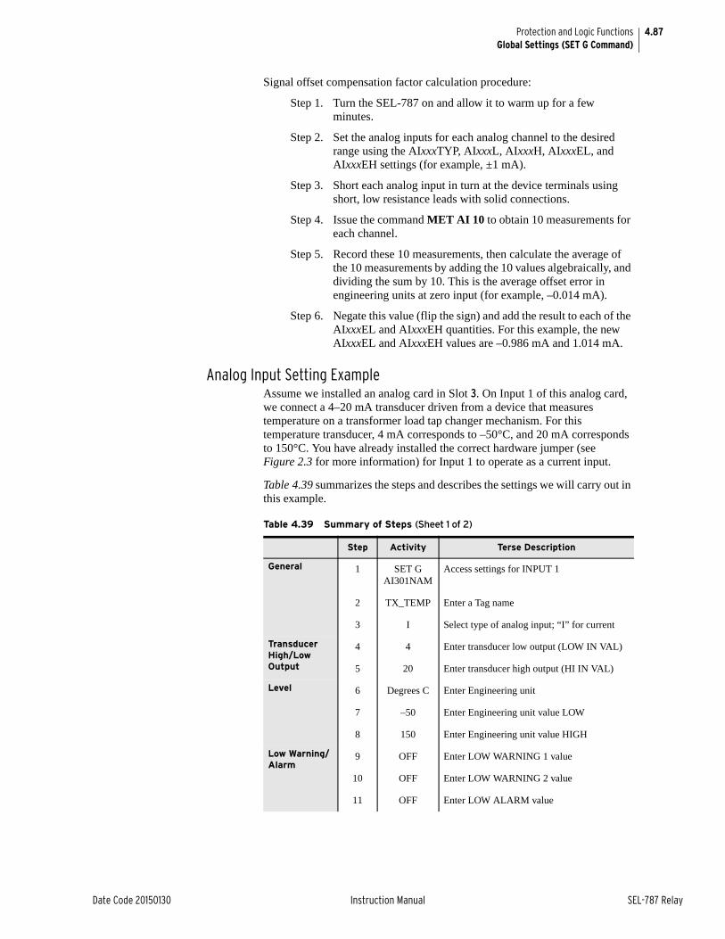
4.87
Date Code 20150130 Instruction Manual SEL-787 Relay
Protection and Logic FunctionsGlobal Settings (SET G Command)
Signal offset compensation factor calculation procedure:
Step 1. Turn the SEL-787 on and allow it to warm up for a few minutes.
Step 2. Set the analog inputs for each analog channel to the desired range using the AIxxxTYP, AIxxxL, AIxxxH, AIxxxEL, and AIxxxEH settings (for example, ±1 mA).
Step 3. Short each analog input in turn at the device terminals using short, low resistance leads with solid connections.
Step 4. Issue the command MET AI 10 to obtain 10 measurements for each channel.
Step 5. Record these 10 measurements, then calculate the average of the 10 measurements by adding the 10 values algebraically, and dividing the sum by 10. This is the average offset error in engineering units at zero input (for example, –0.014 mA).
Step 6. Negate this value (flip the sign) and add the result to each of the AIxxxEL and AIxxxEH quantities. For this example, the new AIxxxEL and AIxxxEH values are –0.986 mA and 1.014 mA.
Analog Input Setting ExampleAssume we installed an analog card in Slot 3. On Input 1 of this analog card, we connect a 4–20 mA transducer driven from a device that measures temperature on a transformer load tap changer mechanism. For this temperature transducer, 4 mA corresponds to –50°C, and 20 mA corresponds to 150°C. You have already installed the correct hardware jumper (see Figure 2.3 for more information) for Input 1 to operate as a current input.
Table 4.39 summarizes the steps and describes the settings we will carry out in this example.
Table 4.39 Summary of Steps (Sheet 1 of 2)
Step Activity Terse Description
General 1 SET G AI301NAM
Access settings for INPUT 1
2 TX_TEMP Enter a Tag name
3 I Select type of analog input; “I” for current
Transducer High/Low Output
4 4 Enter transducer low output (LOW IN VAL)
5 20 Enter transducer high output (HI IN VAL)
Level 6 Degrees C Enter Engineering unit
7 –50 Enter Engineering unit value LOW
8 150 Enter Engineering unit value HIGH
Low Warning/Alarm
9 OFF Enter LOW WARNING 1 value
10 OFF Enter LOW WARNING 2 value
11 OFF Enter LOW ALARM value
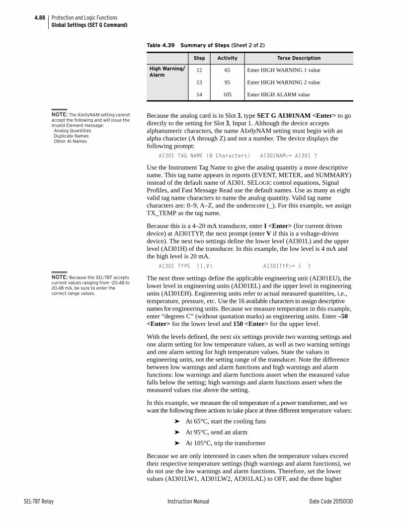
4.88
SEL-787 Relay Instruction Manual Date Code 20150130
Protection and Logic FunctionsGlobal Settings (SET G Command)
NOTE: The AIx0yNAM setting cannot accept the following and will issue the Invalid Element message:Analog QuantitiesDuplicate NamesOther AI Names
Because the analog card is in Slot 3, type SET G AI301NAM <Enter> to go directly to the setting for Slot 3, Input 1. Although the device accepts alphanumeric characters, the name AIx0yNAM setting must begin with an alpha character (A through Z) and not a number. The device displays the following prompt:
AI301 TAG NAME (8 Characters) AI301NAM:= AI301 ?
Use the Instrument Tag Name to give the analog quantity a more descriptive name. This tag name appears in reports (EVENT, METER, and SUMMARY) instead of the default name of AI301. SELOGIC control equations, Signal Profiles, and Fast Message Read use the default names. Use as many as eight valid tag name characters to name the analog quantity. Valid tag name characters are: 0–9, A–Z, and the underscore (_). For this example, we assign TX_TEMP as the tag name.
Because this is a 4–20 mA transducer, enter I <Enter> (for current driven device) at AI301TYP, the next prompt (enter V if this is a voltage-driven device). The next two settings define the lower level (AI301L) and the upper level (AI301H) of the transducer. In this example, the low level is 4 mA and the high level is 20 mA.
AI301 TYPE (I,V) AI301TYP:= I ?
NOTE: Because the SEL-787 accepts current values ranging from –20.48 to 20.48 mA, be sure to enter the correct range values.
The next three settings define the applicable engineering unit (AI301EU), the lower level in engineering units (AI301EL) and the upper level in engineering units (AI301EH). Engineering units refer to actual measured quantities, i.e., temperature, pressure, etc. Use the 16 available characters to assign descriptive names for engineering units. Because we measure temperature in this example, enter “degrees C” (without quotation marks) as engineering units. Enter –50 <Enter> for the lower level and 150 <Enter> for the upper level.
With the levels defined, the next six settings provide two warning settings and one alarm setting for low temperature values, as well as two warning settings and one alarm setting for high temperature values. State the values in engineering units, not the setting range of the transducer. Note the difference between low warnings and alarm functions and high warnings and alarm functions: low warnings and alarm functions assert when the measured value falls below the setting; high warnings and alarm functions assert when the measured values rise above the setting.
In this example, we measure the oil temperature of a power transformer, and we want the following three actions to take place at three different temperature values:
➤ At 65°C, start the cooling fans
➤ At 95°C, send an alarm
➤ At 105°C, trip the transformer
Because we are only interested in cases when the temperature values exceed their respective temperature settings (high warnings and alarm functions), we do not use the low warnings and alarm functions. Therefore, set the lower values (AI301LW1, AI301LW2, AI301LAL) to OFF, and the three higher
High Warning/Alarm
12 65 Enter HIGH WARNING 1 value
13 95 Enter HIGH WARNING 2 value
14 105 Enter HIGH ALARM value
Table 4.39 Summary of Steps (Sheet 2 of 2)
Step Activity Terse Description
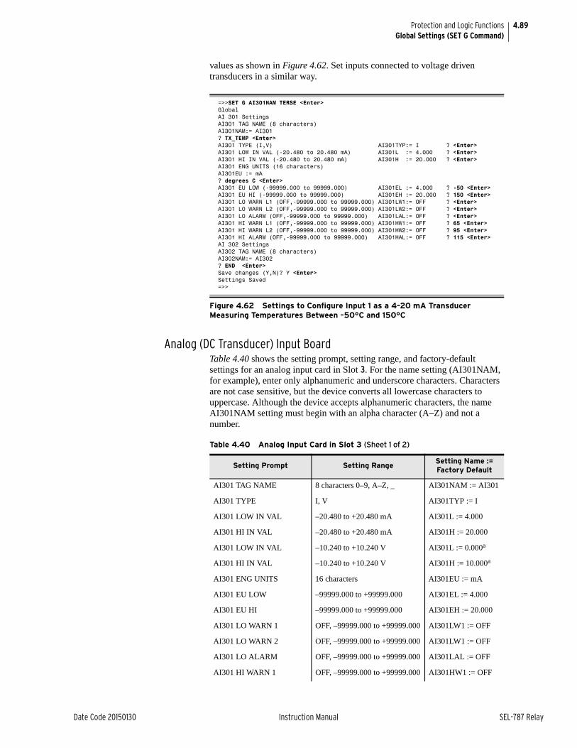
4.89
Date Code 20150130 Instruction Manual SEL-787 Relay
Protection and Logic FunctionsGlobal Settings (SET G Command)
values as shown in Figure 4.62. Set inputs connected to voltage driven transducers in a similar way.
Analog (DC Transducer) Input BoardTable 4.40 shows the setting prompt, setting range, and factory-default settings for an analog input card in Slot 3. For the name setting (AI301NAM, for example), enter only alphanumeric and underscore characters. Characters are not case sensitive, but the device converts all lowercase characters to uppercase. Although the device accepts alphanumeric characters, the name AI301NAM setting must begin with an alpha character (A–Z) and not a number.
=>>SET G AI301NAM TERSE <Enter>GlobalAI 301 SettingsAI301 TAG NAME (8 characters)AI301NAM:= AI301? TX_TEMP <Enter>AI301 TYPE (I,V) AI301TYP:= I ? <Enter> AI301 LOW IN VAL (-20.480 to 20.480 mA) AI301L := 4.000 ? <Enter>AI301 HI IN VAL (-20.480 to 20.480 mA) AI301H := 20.000 ? <Enter>AI301 ENG UNITS (16 characters)AI301EU := mA? degrees C <Enter>AI301 EU LOW (-99999.000 to 99999.000) AI301EL := 4.000 ? -50 <Enter>AI301 EU HI (-99999.000 to 99999.000) AI301EH := 20.000 ? 150 <Enter>AI301 LO WARN L1 (OFF,-99999.000 to 99999.000) AI301LW1:= OFF ? <Enter>AI301 LO WARN L2 (OFF,-99999.000 to 99999.000) AI301LW2:= OFF ? <Enter>AI301 LO ALARM (OFF,-99999.000 to 99999.000) AI301LAL:= OFF ? <Enter>AI301 HI WARN L1 (OFF,-99999.000 to 99999.000) AI301HW1:= OFF ? 65 <Enter>AI301 HI WARN L2 (OFF,-99999.000 to 99999.000) AI301HW2:= OFF ? 95 <Enter>AI301 HI ALARM (OFF,-99999.000 to 99999.000) AI301HAL:= OFF ? 115 <Enter>AI 302 SettingsAI302 TAG NAME (8 characters)AI302NAM:= AI302? END <Enter>Save changes (Y,N)? Y <Enter>Settings Saved=>>
Figure 4.62 Settings to Configure Input 1 as a 4–20 mA Transducer Measuring Temperatures Between –50°C and 150°C
Table 4.40 Analog Input Card in Slot 3 (Sheet 1 of 2)
Setting Prompt Setting RangeSetting Name := Factory Default
AI301 TAG NAME 8 characters 0–9, A–Z, _ AI301NAM := AI301
AI301 TYPE I, V AI301TYP := I
AI301 LOW IN VAL –20.480 to +20.480 mA AI301L := 4.000
AI301 HI IN VAL –20.480 to +20.480 mA AI301H := 20.000
AI301 LOW IN VAL –10.240 to +10.240 V AI301L := 0.000a
AI301 HI IN VAL –10.240 to +10.240 V AI301H := 10.000a
AI301 ENG UNITS 16 characters AI301EU := mA
AI301 EU LOW –99999.000 to +99999.000 AI301EL := 4.000
AI301 EU HI –99999.000 to +99999.000 AI301EH := 20.000
AI301 LO WARN 1 OFF, –99999.000 to +99999.000 AI301LW1 := OFF
AI301 LO WARN 2 OFF, –99999.000 to +99999.000 AI301LW1 := OFF
AI301 LO ALARM OFF, –99999.000 to +99999.000 AI301LAL := OFF
AI301 HI WARN 1 OFF, –99999.000 to +99999.000 AI301HW1 := OFF
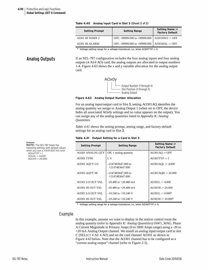
4.90
SEL-787 Relay Instruction Manual Date Code 20150130
Protection and Logic FunctionsGlobal Settings (SET G Command)
Analog Outputs If an SEL-787 configuration includes the four analog inputs and four analog outputs (4 AI/4 AO) card, the analog outputs are allocated to output numbers 1-4. Figure 4.63 shows the x and y variable allocation for the analog output card.
Figure 4.63 Analog Output Number Allocation
For an analog input/output card in Slot 3, setting AO301AQ identifies the analog quantity we assign to Analog Output 1 (when set to OFF, the device hides all associated AOx0y settings and no value appears on the output). You can assign any of the analog quantities listed in Appendix K: Analog Quantities.
Table 4.41 shows the setting prompt, setting range, and factory-default settings for an analog card in Slot 3.
ExampleIn this example, assume we want to display in the station control room the analog quantity (refer to Appendix K: Analog Quantities) IAW1_MAG, Phase A Current Magnitude in Primary Amps (0 to 3000 Amps range) using a -20 to +20 mA Analog Output channel. We install an analog input/output card in slot C (SELECT 4 AI/ 4 AO) and set the card channel AO301 as shown in Figure 4.63 below. Note that the AO301 channel has to be configured as a “current analog output” channel (refer to Figure 2.5).
AI301 HI WARN 2 OFF, –99999.000 to +99999.000 AI301HW2 := OFF
AI301 HI ALARM OFF, –99999.000 to +99999.000 AI301HAL := OFF
a Voltage setting range for a voltage transducer, i.e., when AI301TYP := V.
Table 4.40 Analog Input Card in Slot 3 (Sheet 2 of 2)
Setting Prompt Setting RangeSetting Name := Factory Default
Table 4.41 Output Setting for a Card in Slot 3
Setting Prompt Setting RangeSetting Name := Factory Default
AO301 ANALOG QTY Off, 1 analog quantity AO301AQ := OFF
AO301 TYPE I, V AO301TYP := I
AO301 AQTY LO –2147483647.000 to+2147483647.000
AO301AQL := 4.000
AO301 AQTY HI –2147483647.000 to+2147483647.000
AO301AQH := 20.000
AO301 LO OUT VAL –20.480 to +20.480 mA AO301L := 4.000
AO301 HI OUT VAL –20.480 to +20.480 mA AO301H := 20.000
AO301 LO OUT VAL –10.240 to +10.240 V AO301L := 0.000a
a Voltage setting range for a voltage transducer, i.e., when AO301TYP := V.
AO301 HI OUT VAL –10.240 to +10.240 V AO301H := 10.000a
Output Number (1 through 4)Slot Position (3 through 5)Analog Output
AOx0y
NOTE: The SEL-787 hides the following settings with default values when you use a 3 DI/4 DO/1 AO card:
AOxx1TYP := IAOxx1L := 4.000AOxx1H := 20.000
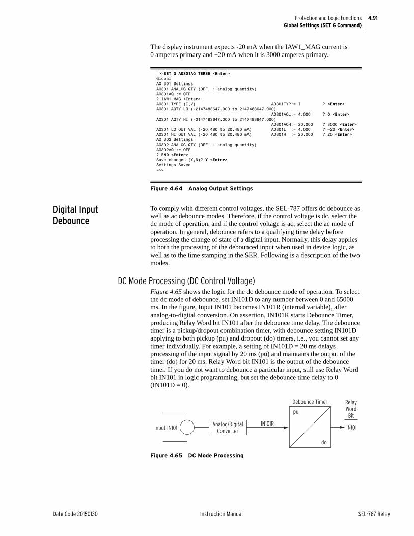
4.91
Date Code 20150130 Instruction Manual SEL-787 Relay
Protection and Logic FunctionsGlobal Settings (SET G Command)
The display instrument expects -20 mA when the IAW1_MAG current is 0 amperes primary and +20 mA when it is 3000 amperes primary.
Digital Input Debounce
To comply with different control voltages, the SEL-787 offers dc debounce as well as ac debounce modes. Therefore, if the control voltage is dc, select the dc mode of operation, and if the control voltage is ac, select the ac mode of operation. In general, debounce refers to a qualifying time delay before processing the change of state of a digital input. Normally, this delay applies to both the processing of the debounced input when used in device logic, as well as to the time stamping in the SER. Following is a description of the two modes.
DC Mode Processing (DC Control Voltage)Figure 4.65 shows the logic for the dc debounce mode of operation. To select the dc mode of debounce, set IN101D to any number between 0 and 65000 ms. In the figure, Input IN101 becomes IN101R (internal variable), after analog-to-digital conversion. On assertion, IN101R starts Debounce Timer, producing Relay Word bit IN101 after the debounce time delay. The debounce timer is a pickup/dropout combination timer, with debounce setting IN101D applying to both pickup (pu) and dropout (do) timers, i.e., you cannot set any timer individually. For example, a setting of IN101D = 20 ms delays processing of the input signal by 20 ms (pu) and maintains the output of the timer (do) for 20 ms. Relay Word bit IN101 is the output of the debounce timer. If you do not want to debounce a particular input, still use Relay Word bit IN101 in logic programming, but set the debounce time delay to 0 (IN101D = 0).
Figure 4.65 DC Mode Processing
=>>SET G AO301AQ TERSE <Enter>GlobalAO 301 SettingsAO301 ANALOG QTY (OFF, 1 analog quantity)AO301AQ := OFF? IAW1_MAG <Enter>AO301 TYPE (I,V) AO301TYP:= I ? <Enter>AO301 AQTY LO (-2147483647.000 to 2147483647.000) AO301AQL:= 4.000 ? 0 <Enter>AO301 AQTY HI (-2147483647.000 to 2147483647.000) AO301AQH:= 20.000 ? 3000 <Enter>AO301 LO OUT VAL (-20.480 to 20.480 mA) AO301L := 4.000 ? –20 <Enter>AO301 HI OUT VAL (-20.480 to 20.480 mA) AO301H := 20.000 ? 20 <Enter>AO 302 SettingsAO302 ANALOG QTY (OFF, 1 analog quantity)AO302AQ := OFF? END <Enter>Save changes (Y,N)? Y <Enter>Settings Saved=>>
Figure 4.64 Analog Output Settings
pu
do
IN101
RelayWordBit
Input IN101IN101RAnalog/Digital
Converter
Debounce Timer
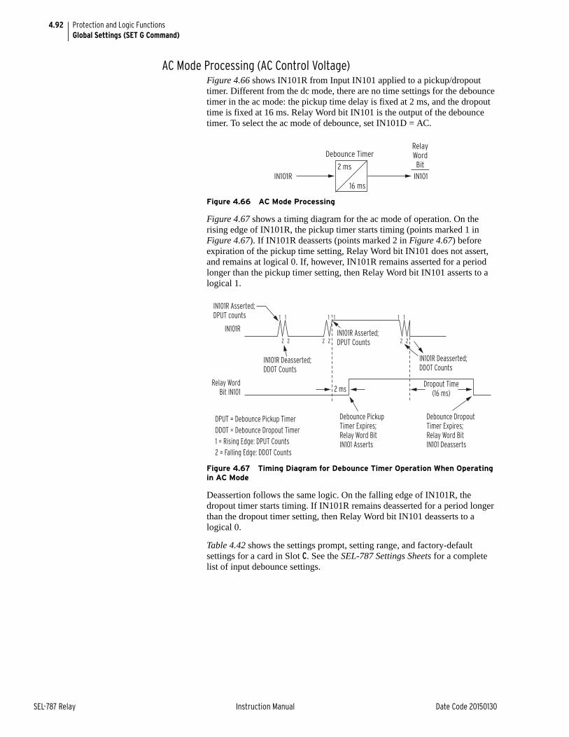
4.92
SEL-787 Relay Instruction Manual Date Code 20150130
Protection and Logic FunctionsGlobal Settings (SET G Command)
AC Mode Processing (AC Control Voltage)Figure 4.66 shows IN101R from Input IN101 applied to a pickup/dropout timer. Different from the dc mode, there are no time settings for the debounce timer in the ac mode: the pickup time delay is fixed at 2 ms, and the dropout time is fixed at 16 ms. Relay Word bit IN101 is the output of the debounce timer. To select the ac mode of debounce, set IN101D = AC.
Figure 4.66 AC Mode Processing
Figure 4.67 shows a timing diagram for the ac mode of operation. On the rising edge of IN101R, the pickup timer starts timing (points marked 1 in Figure 4.67). If IN101R deasserts (points marked 2 in Figure 4.67) before expiration of the pickup time setting, Relay Word bit IN101 does not assert, and remains at logical 0. If, however, IN101R remains asserted for a period longer than the pickup timer setting, then Relay Word bit IN101 asserts to a logical 1.
Figure 4.67 Timing Diagram for Debounce Timer Operation When Operating in AC Mode
Deassertion follows the same logic. On the falling edge of IN101R, the dropout timer starts timing. If IN101R remains deasserted for a period longer than the dropout timer setting, then Relay Word bit IN101 deasserts to a logical 0.
Table 4.42 shows the settings prompt, setting range, and factory-default settings for a card in Slot C. See the SEL-787 Settings Sheets for a complete list of input debounce settings.
2 ms
16 msIN101
RelayWordBit
IN101R
Debounce Timer
IN101R
2 ms
IN101R Deasserted;DDOT Counts
IN101R Deasserted;DDOT Counts
Dropout Time(16 ms)
Debounce Dropout Timer Expires; Relay Word Bit IN101 Deasserts
Debounce Pickup Timer Expires; Relay Word Bit IN101 Asserts
IN101R Asserted;DPUT Counts
IN101R Asserted;DPUT counts
Relay WordBit IN101
1
2
1 1 1 1 1
2 2 2 2 2
DPUT = Debounce Pickup TimerDDOT = Debounce Dropout Timer1 = Rising Edge: DPUT Counts2 = Falling Edge: DDOT Counts
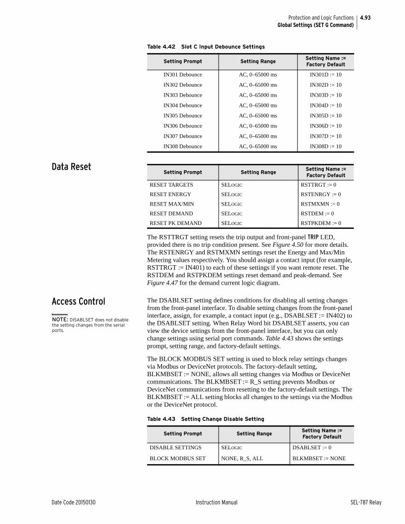
4.93
Date Code 20150130 Instruction Manual SEL-787 Relay
Protection and Logic FunctionsGlobal Settings (SET G Command)
Data Reset
The RSTTRGT setting resets the trip output and front-panel TRIP LED, provided there is no trip condition present. See Figure 4.50 for more details. The RSTENRGY and RSTMXMN settings reset the Energy and Max/Min Metering values respectively. You should assign a contact input (for example, RSTTRGT := IN401) to each of these settings if you want remote reset. The RSTDEM and RSTPKDEM settings reset demand and peak-demand. See Figure 4.47 for the demand current logic diagram.
Access Control The DSABLSET setting defines conditions for disabling all setting changes from the front-panel interface. To disable setting changes from the front-panel interface, assign, for example, a contact input (e.g., DSABLSET := IN402) to the DSABLSET setting. When Relay Word bit DSABLSET asserts, you can view the device settings from the front-panel interface, but you can only change settings using serial port commands. Table 4.43 shows the settings prompt, setting range, and factory-default settings.
The BLOCK MODBUS SET setting is used to block relay settings changes via Modbus or DeviceNet protocols. The factory-default setting, BLKMBSET := NONE, allows all setting changes via Modbus or DeviceNet communications. The BLKMBSET := R_S setting prevents Modbus or DeviceNet communications from resetting to the factory-default settings. The BLKMBSET := ALL setting blocks all changes to the settings via the Modbus or the DeviceNet protocol.
Table 4.42 Slot C Input Debounce Settings
Setting Prompt Setting RangeSetting Name := Factory Default
IN301 Debounce AC, 0–65000 ms IN301D := 10
IN302 Debounce AC, 0–65000 ms IN302D := 10
IN303 Debounce AC, 0–65000 ms IN303D := 10
IN304 Debounce AC, 0–65000 ms IN304D := 10
IN305 Debounce AC, 0–65000 ms IN305D := 10
IN306 Debounce AC, 0–65000 ms IN306D := 10
IN307 Debounce AC, 0–65000 ms IN307D := 10
IN308 Debounce AC, 0–65000 ms IN308D := 10
Setting Prompt Setting RangeSetting Name := Factory Default
RESET TARGETS SELOGIC RSTTRGT := 0
RESET ENERGY SELOGIC RSTENRGY := 0
RESET MAX/MIN SELOGIC RSTMXMN := 0
RESET DEMAND SELOGIC RSTDEM := 0
RESET PK DEMAND SELOGIC RSTPKDEM := 0
Table 4.43 Setting Change Disable Setting
Setting Prompt Setting RangeSetting Name := Factory Default
DISABLE SETTINGS SELOGIC DSABLSET := 0
BLOCK MODBUS SET NONE, R_S, ALL BLKMBSET := NONE
NOTE: DISABLSET does not disable the setting changes from the serial ports.
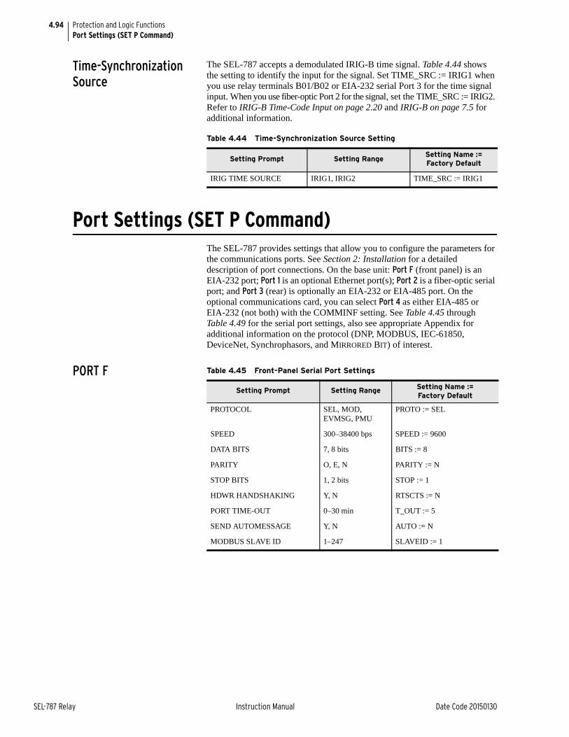
4.94
SEL-787 Relay Instruction Manual Date Code 20150130
Protection and Logic FunctionsPort Settings (SET P Command)
Time-Synchronization Source
The SEL-787 accepts a demodulated IRIG-B time signal. Table 4.44 shows the setting to identify the input for the signal. Set TIME_SRC := IRIG1 when you use relay terminals B01/B02 or EIA-232 serial Port 3 for the time signal input. When you use fiber-optic Port 2 for the signal, set the TIME_SRC := IRIG2. Refer to IRIG-B Time-Code Input on page 2.20 and IRIG-B on page 7.5 for additional information.
Port Settings (SET P Command)The SEL-787 provides settings that allow you to configure the parameters for the communications ports. See Section 2: Installation for a detailed description of port connections. On the base unit: Port F (front panel) is an EIA-232 port; Port 1 is an optional Ethernet port(s); Port 2 is a fiber-optic serial port; and Port 3 (rear) is optionally an EIA-232 or EIA-485 port. On the optional communications card, you can select Port 4 as either EIA-485 or EIA-232 (not both) with the COMMINF setting. See Table 4.45 through Table 4.49 for the serial port settings, also see appropriate Appendix for additional information on the protocol (DNP, MODBUS, IEC-61850, DeviceNet, Synchrophasors, and MIRRORED BIT) of interest.
PORT F
Table 4.44 Time-Synchronization Source Setting
Setting Prompt Setting RangeSetting Name := Factory Default
IRIG TIME SOURCE IRIG1, IRIG2 TIME_SRC := IRIG1
Table 4.45 Front-Panel Serial Port Settings
Setting Prompt Setting Range Setting Name := Factory Default
PROTOCOL SEL, MOD, EVMSG, PMU
PROTO := SEL
SPEED 300–38400 bps SPEED := 9600
DATA BITS 7, 8 bits BITS := 8
PARITY O, E, N PARITY := N
STOP BITS 1, 2 bits STOP := 1
HDWR HANDSHAKING Y, N RTSCTS := N
PORT TIME-OUT 0–30 min T_OUT := 5
SEND AUTOMESSAGE Y, N AUTO := N
MODBUS SLAVE ID 1–247 SLAVEID := 1
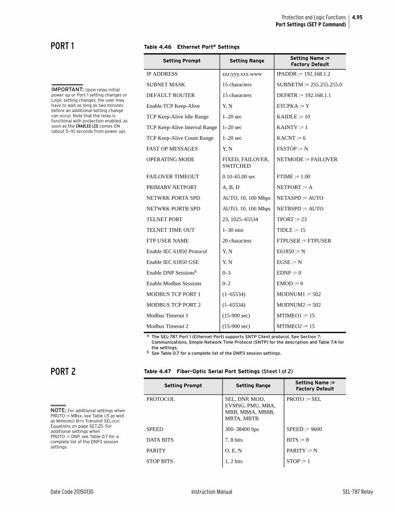
4.95
Date Code 20150130 Instruction Manual SEL-787 Relay
Protection and Logic FunctionsPort Settings (SET P Command)
PORT 1
PORT 2
Table 4.46 Ethernet Porta Settings
a The SEL-787 Port 1 (Ethernet Port) supports SNTP Client protocol. See Section 7: Communications, Simple Network Time Protocol (SNTP) for the description and Table 7.4 for the settings.
Setting Prompt Setting Range Setting Name := Factory Default
IP ADDRESS zzz.yyy.xxx.www IPADDR := 192.168.1.2
SUBNET MASK 15 characters SUBNETM := 255.255.255.0
DEFAULT ROUTER 15 characters DEFRTR := 192.168.1.1
Enable TCP Keep-Alive Y, N ETCPKA := Y
TCP Keep-Alive Idle Range 1–20 sec KAIDLE := 10
TCP Keep-Alive Interval Range 1–20 sec KAINTV := 1
TCP Keep-Alive Count Range 1–20 sec KACNT := 6
FAST OP MESSAGES Y, N FASTOP := N
OPERATING MODE FIXED, FAILOVER, SWITCHED
NETMODE := FAILOVER
FAILOVER TIMEOUT 0.10–65.00 sec FTIME := 1.00
PRIMARY NETPORT A, B, D NETPORT := A
NETWRK PORTA SPD AUTO, 10, 100 Mbps NETASPD := AUTO
NETWRK PORTB SPD AUTO, 10, 100 Mbps NETBSPD := AUTO
TELNET PORT 23, 1025–65534 TPORT := 23
TELNET TIME OUT 1–30 min TIDLE := 15
FTP USER NAME 20 characters FTPUSER := FTPUSER
Enable IEC 61850 Protocol Y, N E61850 := N
Enable IEC 61850 GSE Y, N EGSE := N
Enable DNP Sessionsb
b See Table D.7 for a complete list of the DNP3 session settings.
0–3 EDNP := 0
Enable Modbus Sessions 0–2 EMOD := 0
MODBUS TCP PORT 1 (1–65534) MODNUM1 := 502
MODBUS TCP PORT 2 (1–65534) MODNUM2 := 502
Modbus Timeout 1 (15-900 sec) MTIMEO1 := 15
Modbus Timeout 2 (15-900 sec) MTIMEO2 := 15
IMPORTANT: Upon relay initial power up or Port 1 setting changes or Logic setting changes, the user may have to wait as long as two minutes before an additional setting change can occur. Note that the relay is functional with protection enabled, as soon as the ENABLED LED comes ON (about 5—10 seconds from power up).
Table 4.47 Fiber-Optic Serial Port Settings (Sheet 1 of 2)
Setting Prompt Setting RangeSetting Name := Factory Default
PROTOCOL SEL, DNP, MOD, EVMSG, PMU, MBA, MBB, MB8A, MB8B, MBTA, MBTB
PROTO := SEL
SPEED 300–38400 bps SPEED := 9600
DATA BITS 7, 8 bits BITS := 8
PARITY O, E, N PARITY := N
STOP BITS 1, 2 bits STOP := 1
NOTE: For additional settings when PROTO := MBxx, see Table I.5 as well as MIRRORED BITS Transmit SELOGIC Equations on page SET.25. For additional settings when PROTO := DNP, see Table D.7 for a complete list of the DNP3 session settings.
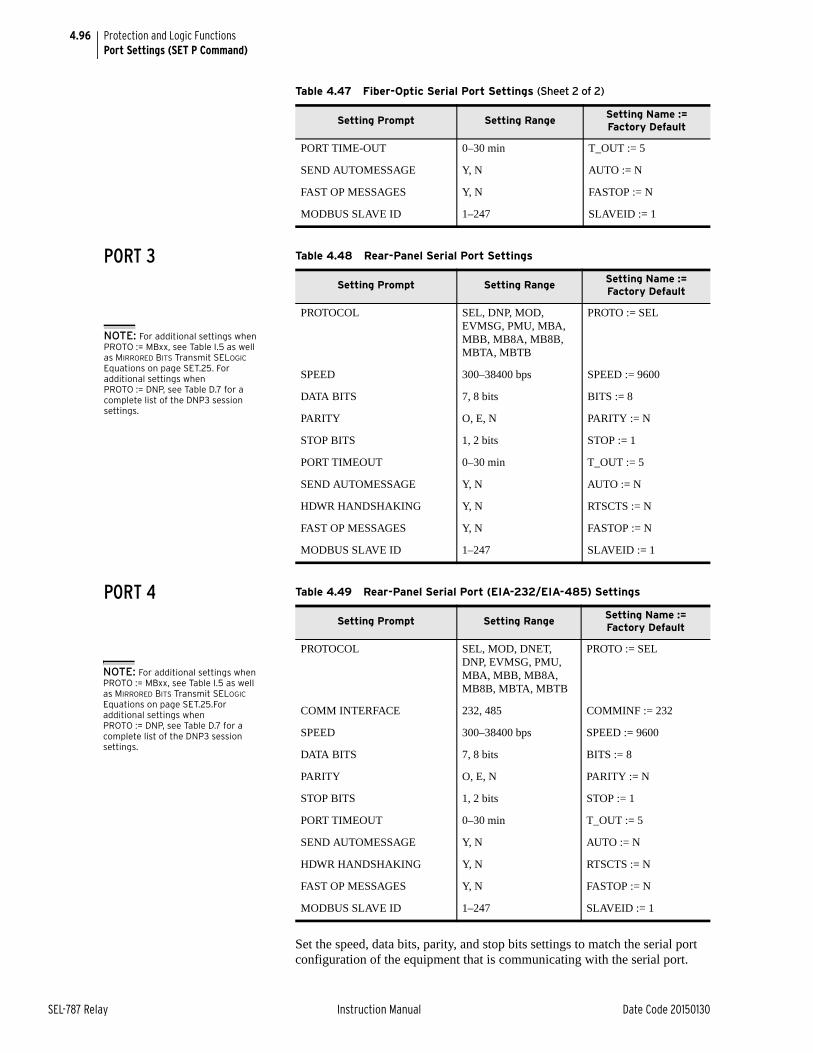
4.96
SEL-787 Relay Instruction Manual Date Code 20150130
Protection and Logic FunctionsPort Settings (SET P Command)
PORT 3
PORT 4
Set the speed, data bits, parity, and stop bits settings to match the serial port configuration of the equipment that is communicating with the serial port.
PORT TIME-OUT 0–30 min T_OUT := 5
SEND AUTOMESSAGE Y, N AUTO := N
FAST OP MESSAGES Y, N FASTOP := N
MODBUS SLAVE ID 1–247 SLAVEID := 1
Table 4.47 Fiber-Optic Serial Port Settings (Sheet 2 of 2)
Setting Prompt Setting RangeSetting Name := Factory Default
Table 4.48 Rear-Panel Serial Port Settings
Setting Prompt Setting RangeSetting Name := Factory Default
PROTOCOL SEL, DNP, MOD, EVMSG, PMU, MBA, MBB, MB8A, MB8B, MBTA, MBTB
PROTO := SEL
SPEED 300–38400 bps SPEED := 9600
DATA BITS 7, 8 bits BITS := 8
PARITY O, E, N PARITY := N
STOP BITS 1, 2 bits STOP := 1
PORT TIMEOUT 0–30 min T_OUT := 5
SEND AUTOMESSAGE Y, N AUTO := N
HDWR HANDSHAKING Y, N RTSCTS := N
FAST OP MESSAGES Y, N FASTOP := N
MODBUS SLAVE ID 1–247 SLAVEID := 1
NOTE: For additional settings when PROTO := MBxx, see Table I.5 as well as MIRRORED BITS Transmit SELOGIC Equations on page SET.25. For additional settings when PROTO := DNP, see Table D.7 for a complete list of the DNP3 session settings.
Table 4.49 Rear-Panel Serial Port (EIA-232/EIA-485) Settings
Setting Prompt Setting RangeSetting Name := Factory Default
PROTOCOL SEL, MOD, DNET, DNP, EVMSG, PMU, MBA, MBB, MB8A, MB8B, MBTA, MBTB
PROTO := SEL
COMM INTERFACE 232, 485 COMMINF := 232
SPEED 300–38400 bps SPEED := 9600
DATA BITS 7, 8 bits BITS := 8
PARITY O, E, N PARITY := N
STOP BITS 1, 2 bits STOP := 1
PORT TIMEOUT 0–30 min T_OUT := 5
SEND AUTOMESSAGE Y, N AUTO := N
HDWR HANDSHAKING Y, N RTSCTS := N
FAST OP MESSAGES Y, N FASTOP := N
MODBUS SLAVE ID 1–247 SLAVEID := 1
NOTE: For additional settings when PROTO := MBxx, see Table I.5 as well as MIRRORED BITS Transmit SELOGIC Equations on page SET.25.For additional settings when PROTO := DNP, see Table D.7 for a complete list of the DNP3 session settings.
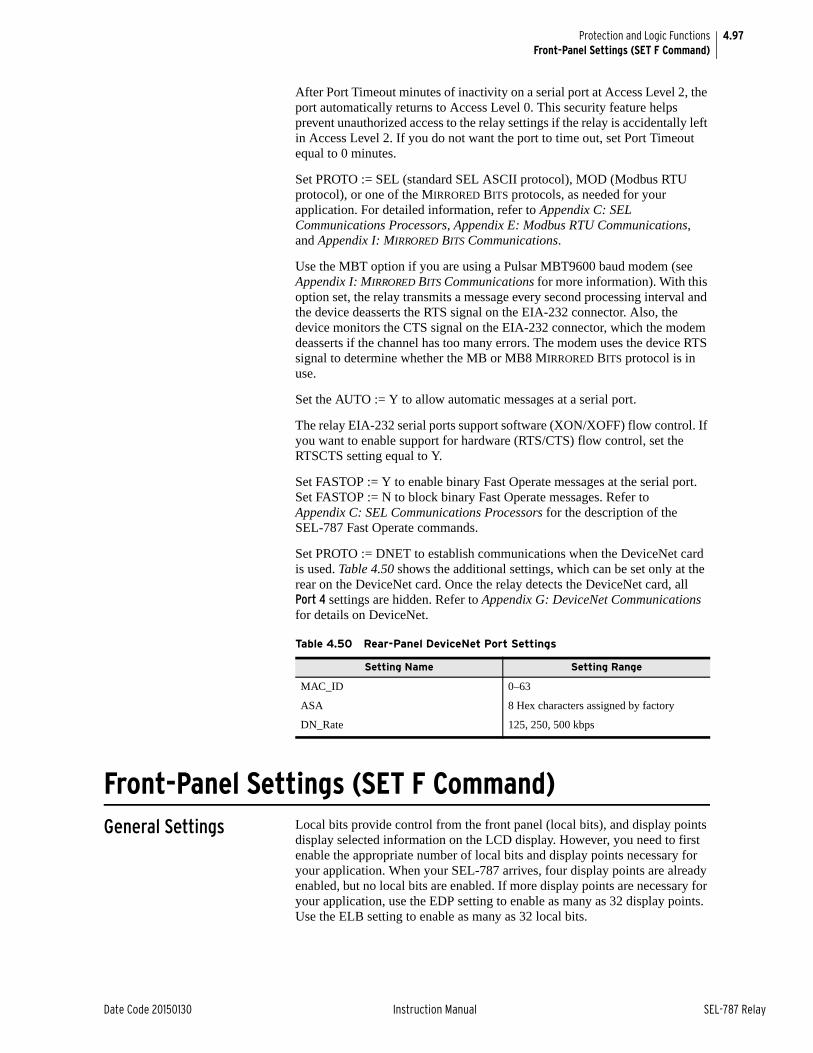
4.97
Date Code 20150130 Instruction Manual SEL-787 Relay
Protection and Logic FunctionsFront-Panel Settings (SET F Command)
After Port Timeout minutes of inactivity on a serial port at Access Level 2, the port automatically returns to Access Level 0. This security feature helps prevent unauthorized access to the relay settings if the relay is accidentally left in Access Level 2. If you do not want the port to time out, set Port Timeout equal to 0 minutes.
Set PROTO := SEL (standard SEL ASCII protocol), MOD (Modbus RTU protocol), or one of the MIRRORED BITS protocols, as needed for your application. For detailed information, refer to Appendix C: SEL Communications Processors, Appendix E: Modbus RTU Communications, and Appendix I: MIRRORED BITS Communications.
Use the MBT option if you are using a Pulsar MBT9600 baud modem (see Appendix I: MIRRORED BITS Communications for more information). With this option set, the relay transmits a message every second processing interval and the device deasserts the RTS signal on the EIA-232 connector. Also, the device monitors the CTS signal on the EIA-232 connector, which the modem deasserts if the channel has too many errors. The modem uses the device RTS signal to determine whether the MB or MB8 MIRRORED BITS protocol is in use.
Set the AUTO := Y to allow automatic messages at a serial port.
The relay EIA-232 serial ports support software (XON/XOFF) flow control. If you want to enable support for hardware (RTS/CTS) flow control, set the RTSCTS setting equal to Y.
Set FASTOP := Y to enable binary Fast Operate messages at the serial port. Set FASTOP := N to block binary Fast Operate messages. Refer to Appendix C: SEL Communications Processors for the description of the SEL-787 Fast Operate commands.
Set PROTO := DNET to establish communications when the DeviceNet card is used. Table 4.50 shows the additional settings, which can be set only at the rear on the DeviceNet card. Once the relay detects the DeviceNet card, all Port 4 settings are hidden. Refer to Appendix G: DeviceNet Communications for details on DeviceNet.
Front-Panel Settings (SET F Command)General Settings Local bits provide control from the front panel (local bits), and display points
display selected information on the LCD display. However, you need to first enable the appropriate number of local bits and display points necessary for your application. When your SEL-787 arrives, four display points are already enabled, but no local bits are enabled. If more display points are necessary for your application, use the EDP setting to enable as many as 32 display points. Use the ELB setting to enable as many as 32 local bits.
Table 4.50 Rear-Panel DeviceNet Port Settings
Setting Name Setting Range
MAC_ID 0–63
ASA 8 Hex characters assigned by factory
DN_Rate 125, 250, 500 kbps
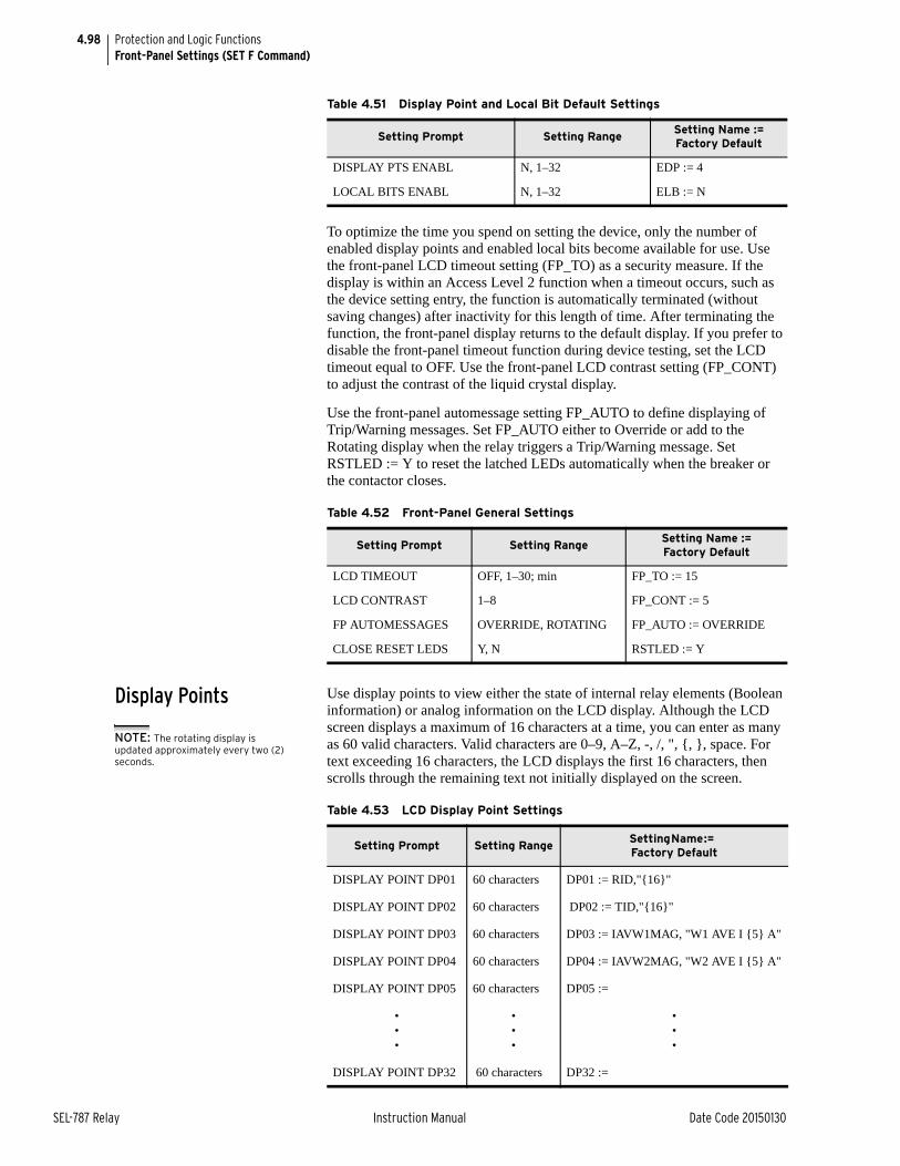
4.98
SEL-787 Relay Instruction Manual Date Code 20150130
Protection and Logic FunctionsFront-Panel Settings (SET F Command)
To optimize the time you spend on setting the device, only the number of enabled display points and enabled local bits become available for use. Use the front-panel LCD timeout setting (FP_TO) as a security measure. If the display is within an Access Level 2 function when a timeout occurs, such as the device setting entry, the function is automatically terminated (without saving changes) after inactivity for this length of time. After terminating the function, the front-panel display returns to the default display. If you prefer to disable the front-panel timeout function during device testing, set the LCD timeout equal to OFF. Use the front-panel LCD contrast setting (FP_CONT) to adjust the contrast of the liquid crystal display.
Use the front-panel automessage setting FP_AUTO to define displaying of Trip/Warning messages. Set FP_AUTO either to Override or add to the Rotating display when the relay triggers a Trip/Warning message. Set RSTLED := Y to reset the latched LEDs automatically when the breaker or the contactor closes.
Display Points Use display points to view either the state of internal relay elements (Boolean information) or analog information on the LCD display. Although the LCD screen displays a maximum of 16 characters at a time, you can enter as many as 60 valid characters. Valid characters are 0–9, A–Z, -, /, ", {, }, space. For text exceeding 16 characters, the LCD displays the first 16 characters, then scrolls through the remaining text not initially displayed on the screen.
Table 4.51 Display Point and Local Bit Default Settings
Setting Prompt Setting RangeSetting Name := Factory Default
DISPLAY PTS ENABL N, 1–32 EDP := 4
LOCAL BITS ENABL N, 1–32 ELB := N
Table 4.52 Front-Panel General Settings
Setting Prompt Setting RangeSetting Name := Factory Default
LCD TIMEOUT OFF, 1–30; min FP_TO := 15
LCD CONTRAST 1–8 FP_CONT := 5
FP AUTOMESSAGES OVERRIDE, ROTATING FP_AUTO := OVERRIDE
CLOSE RESET LEDS Y, N RSTLED := Y
Table 4.53 LCD Display Point Settings
Setting Prompt Setting RangeSetting Name := Factory Default
DISPLAY POINT DP01 60 characters DP01 := RID,"{16}"
DISPLAY POINT DP02 60 characters DP02 := TID,"{16}"
DISPLAY POINT DP03 60 characters DP03 := IAVW1MAG, "W1 AVE I {5} A"
DISPLAY POINT DP04 60 characters DP04 := IAVW2MAG, "W2 AVE I {5} A"
DISPLAY POINT DP05 60 characters DP05 :=
•••
•••
•••
DISPLAY POINT DP32 60 characters DP32 :=
NOTE: The rotating display is updated approximately every two (2) seconds.
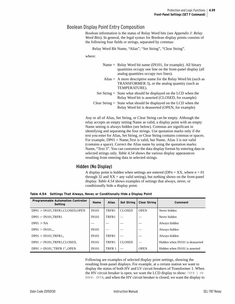
4.99
Date Code 20150130 Instruction Manual SEL-787 Relay
Protection and Logic FunctionsFront-Panel Settings (SET F Command)
Boolean Display Point Entry CompositionBoolean information is the status of Relay Word bits (see Appendix J: Relay Word Bits). In general, the legal syntax for Boolean display points consists of the following four fields or strings, separated by commas:
Relay Word Bit Name, “Alias”, “Set String”, “Clear String”.
where:
Any or all of Alias, Set String, or Clear String can be empty. Although the relay accepts an empty setting Name as valid, a display point with an empty Name setting is always hidden (see below). Commas are significant in identifying and separating the four strings. Use quotation marks only if the text you enter for Alias, Set String, or Clear String contains commas or spaces. For example, DP01 = Name,Text is valid, but Name, Alias 3 is not valid (contains a space). Correct the Alias name by using the quotation marks: Name, “Text 3”. You can customize the data display format by entering data in selected strings only. Table 4.54 shows the various display appearances resulting from entering data in selected strings.
Hidden (No Display)A display point is hidden when settings are entered (DPn = XX, where n = 01 through 32 and XX = any valid setting), but nothing shows on the front-panel display. Table 4.54 shows examples of settings that always, never, or conditionally hide a display point.
Following are examples of selected display point settings, showing the resulting front-panel displays. For example, at a certain station we want to display the status of both HV and LV circuit breakers of Transformer 1. When the HV circuit breaker is open, we want the LCD display to show: TRFR 1 HV BRKR: OPEN, and when the HV circuit breaker is closed, we want the display to
Name = Relay Word bit name (IN101, for example). All binary quantities occupy one line on the front-panel display (all analog quantities occupy two lines).
Alias = A more descriptive name for the Relay Word bit (such as TRANSFORMER 3), or the analog quantity (such as TEMPERATURE).
Set String = State what should be displayed on the LCD when the Relay Word bit is asserted (CLOSED, for example)
Clear String = State what should be displayed on the LCD when the Relay Word bit is deasserted (OPEN, for example)
Table 4.54 Settings That Always, Never, or Conditionally Hide a Display Point
Programmable Automation Controller Setting
Name Alias Set String Clear String Comment
DP01 := IN101,TRFR1,CLOSED,OPEN IN101 TRFR1 CLOSED OPEN Never hidden
DP01 := IN101,TRFR1 IN101 TRFR1 — — Never hidden
DP01 := NA — — — — Always hidden
DP01 := IN101,,, IN101 — — — Always hidden
DP01 := IN101,TRFR1,, IN101 TRFR1 — — Always hidden
DP01 := IN101,TRFR1,CLOSED, IN101 TRFR1 CLOSED — Hidden when IN101 is deasserted
DP01 := IN101,"TRFR 1",,OPEN IN101 TRFR 1 — OPEN Hidden when IN101 is asserted
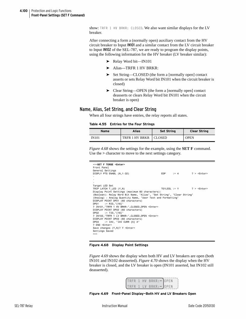
4.100
SEL-787 Relay Instruction Manual Date Code 20150130
Protection and Logic FunctionsFront-Panel Settings (SET F Command)
show: TRFR 1 HV BRKR: CLOSED. We also want similar displays for the LV breaker.
After connecting a form a (normally open) auxiliary contact from the HV circuit breaker to Input IN101 and a similar contact from the LV circuit breaker to Input IN102 of the SEL-787, we are ready to program the display points, using the following information for the HV breaker (LV breaker similar):
➤ Relay Word bit—IN101
➤ Alias—TRFR 1 HV BRKR:
➤ Set String—CLOSED (the form a [normally open] contact asserts or sets Relay Word bit IN101 when the circuit breaker is closed)
➤ Clear String—OPEN (the form a [normally open] contact deasserts or clears Relay Word bit IN101 when the circuit breaker is open)
Name, Alias, Set String, and Clear StringWhen all four strings have entries, the relay reports all states.
Figure 4.68 shows the settings for the example, using the SET F command. Use the > character to move to the next settings category.
Figure 4.69 shows the display when both HV and LV breakers are open (both IN101 and IN102 deasserted). Figure 4.70 shows the display when the HV breaker is closed, and the LV breaker is open (IN101 asserted, but IN102 still deasserted).
Figure 4.69 Front-Panel Display—Both HV and LV Breakers Open
Table 4.55 Entries for the Four Strings
Name Alias Set String Clear String
IN101 TRFR 1 HV BRKR CLOSED OPEN
=>>SET F TERSE <Enter>Front PanelGeneral SettingsDISPLY PTS ENABL (N,1-32) EDP := 4 ? > <Enter>•••Target LED SetTRIP LATCH T_LED (Y,N) T01LEDL := Y ? > <Enter>Display Point Settings (maximum 60 characters):(Boolean): Relay Word Bit Name, "Alias", "Set String", "Clear String"(Analog) : Analog Quantity Name, "User Text and Formatting"DISPLAY POINT DP01 (60 characters)DP01 := RID,"{16}"? IN101,"TRFR 1 HV BRKR:",CLOSED,OPEN <Enter>DISPLAY POINT DP02 (60 characters)DP02 := TID,"{16}"? IN102,"TRFR 1 LV BRKR:",CLOSED,OPEN <Enter>DISPLAY POINT DP03 (60 characters)DP03 := IAV, "IAV CURR {5} A"? END <Enter>Save changes (Y,N)? Y <Enter>Settings Saved=>>
Figure 4.68 Display Point Settings
TRFR 1 HV BRKR:= OPENTRFR 1 LV BRKR:= OPEN
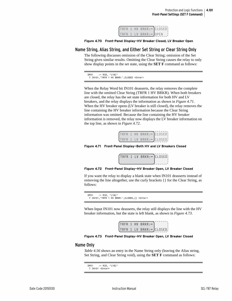
4.101
Date Code 20150130 Instruction Manual SEL-787 Relay
Protection and Logic FunctionsFront-Panel Settings (SET F Command)
Figure 4.70 Front-Panel Display—HV Breaker Closed, LV Breaker Open
Name String, Alias String, and Either Set String or Clear String OnlyThe following discusses omission of the Clear String; omission of the Set String gives similar results. Omitting the Clear String causes the relay to only show display points in the set state, using the SET F command as follows:
When the Relay Word bit IN101 deasserts, the relay removes the complete line with the omitted Clear String (TRFR 1 HV BRKR). When both breakers are closed, the relay has the set state information for both HV and LV breakers, and the relay displays the information as shown in Figure 4.71. When the HV breaker opens (LV breaker is still closed), the relay removes the line containing the HV breaker information because the Clear String information was omitted. Because the line containing the HV breaker information is removed, the relay now displays the LV breaker information on the top line, as shown in Figure 4.72.
Figure 4.71 Front-Panel Display—Both HV and LV Breakers Closed
Figure 4.72 Front-Panel Display—HV Breaker Open, LV Breaker Closed
If you want the relay to display a blank state when IN101 deasserts instead of removing the line altogether, use the curly brackets {} for the Clear String, as follows:
When Input IN101 now deasserts, the relay still displays the line with the HV breaker information, but the state is left blank, as shown in Figure 4.73.
Figure 4.73 Front-Panel Display—HV Breaker Open, LV Breaker Closed
Name OnlyTable 4.56 shows an entry in the Name String only (leaving the Alias string, Set String, and Clear String void), using the SET F command as follows:
TRFR 1 HV BRKR:= CLOSEDTRFR 1 LV BRKR:= OPEN
DP01 := RID, “{16}” ? IN101,"TRFR 1 HV BRKR:",CLOSED <Enter>
DP01 := RID, “{16}” ? IN101,"TRFR 1 HV BRKR:",CLOSED,{} <Enter>
TRFR 1 HV BRKR:= CLOSEDTRFR 1 LV BRKR:= CLOSED
TRFR 1 LV BRKR:= CLOSED
TRFR 1 HV BRKR:=TRFR 1 LV BRKR:= CLOSED
DP01 := RID, “{16}” ? IN101 <Enter>
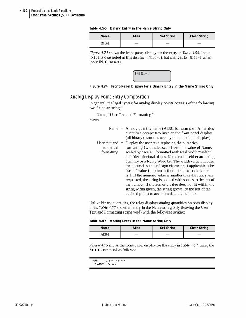
4.102
SEL-787 Relay Instruction Manual Date Code 20150130
Protection and Logic FunctionsFront-Panel Settings (SET F Command)
Figure 4.74 shows the front-panel display for the entry in Table 4.56. Input IN101 is deasserted in this display (IN101=0), but changes to IN101=1 when Input IN101 asserts.
Figure 4.74 Front-Panel Display for a Binary Entry in the Name String Only
Analog Display Point Entry CompositionIn general, the legal syntax for analog display points consists of the following two fields or strings:
Name, “User Text and Formatting.”where:
Unlike binary quantities, the relay displays analog quantities on both display lines. Table 4.57 shows an entry in the Name string only (leaving the User Text and Formatting string void) with the following syntax:
Figure 4.75 shows the front-panel display for the entry in Table 4.57, using the SET F command as follows:
Table 4.56 Binary Entry in the Name String Only
Name Alias Set String Clear String
IN101 — — —
IN101=0
Name = Analog quantity name (AI301 for example). All analog quantities occupy two lines on the front-panel display (all binary quantities occupy one line on the display).
User text andnumericalformatting
= Display the user text, replacing the numerical formatting {width.dec,scale} with the value of Name, scaled by “scale”, formatted with total width “width” and “dec” decimal places. Name can be either an analog quantity or a Relay Word bit. The width value includes the decimal point and sign character, if applicable. The “scale” value is optional; if omitted, the scale factor is 1. If the numeric value is smaller than the string size requested, the string is padded with spaces to the left of the number. If the numeric value does not fit within the string width given, the string grows (to the left of the decimal point) to accommodate the number.
Table 4.57 Analog Entry in the Name String Only
Name Alias Set String Clear String
AI301 — — —
DP01 := RID, “{16}” ? AI301 <Enter>
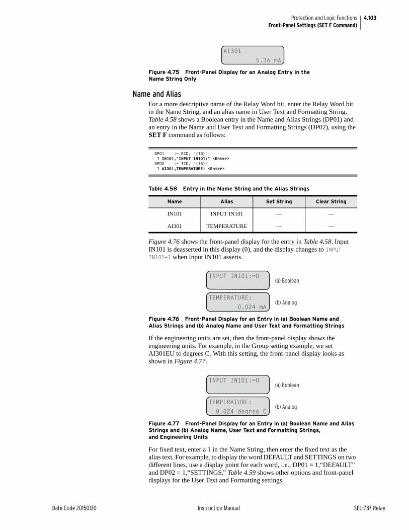
4.103
Date Code 20150130 Instruction Manual SEL-787 Relay
Protection and Logic FunctionsFront-Panel Settings (SET F Command)
Figure 4.75 Front-Panel Display for an Analog Entry in the Name String Only
Name and AliasFor a more descriptive name of the Relay Word bit, enter the Relay Word bit in the Name String, and an alias name in User Text and Formatting String. Table 4.58 shows a Boolean entry in the Name and Alias Strings (DP01) and an entry in the Name and User Text and Formatting Strings (DP02), using the SET F command as follows:
Figure 4.76 shows the front-panel display for the entry in Table 4.58. Input IN101 is deasserted in this display (0), and the display changes to INPUT IN101=1 when Input IN101 asserts.
Figure 4.76 Front-Panel Display for an Entry in (a) Boolean Name and Alias Strings and (b) Analog Name and User Text and Formatting Strings
If the engineering units are set, then the front-panel display shows the engineering units. For example, in the Group setting example, we set AI301EU to degrees C. With this setting, the front-panel display looks as shown in Figure 4.77.
Figure 4.77 Front-Panel Display for an Entry in (a) Boolean Name and Alias Strings and (b) Analog Name, User Text and Formatting Strings, and Engineering Units
For fixed text, enter a 1 in the Name String, then enter the fixed text as the alias text. For example, to display the word DEFAULT and SETTINGS on two different lines, use a display point for each word, i.e., DP01 = 1,“DEFAULT” and DP02 = 1,“SETTINGS.” Table 4.59 shows other options and front-panel displays for the User Text and Formatting settings.
AI301 5.36 mA
DP01 := RID, “{16}” ? IN101,"INPUT IN101:" <Enter>DP02 := TID, “{16}” ? AI301,TEMPERATURE: <Enter>
Table 4.58 Entry in the Name String and the Alias Strings
Name Alias Set String Clear String
IN101 INPUT IN101 — —
AI301 TEMPERATURE — —
INPUT IN101:=0
TEMPERATURE: 0.024 mA
(a) Boolean
(b) Analog
INPUT IN101:=0
TEMPERATURE: 0.024 degree C
(a) Boolean
(b) Analog
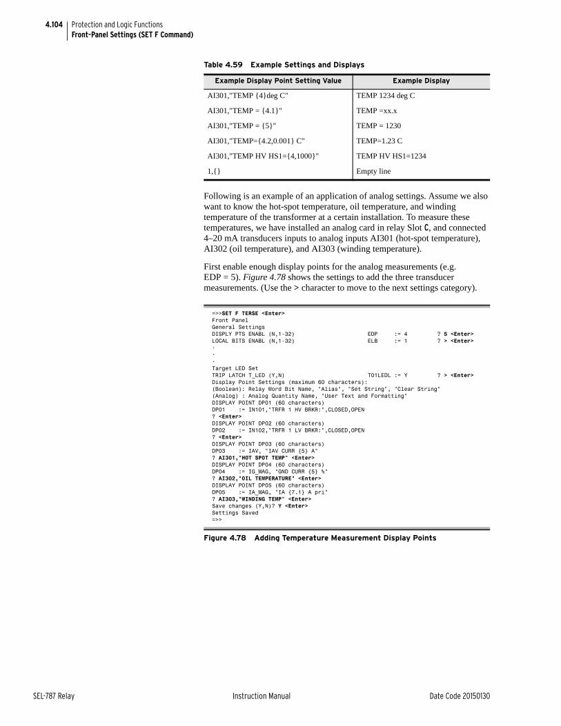
4.104
SEL-787 Relay Instruction Manual Date Code 20150130
Protection and Logic FunctionsFront-Panel Settings (SET F Command)
Following is an example of an application of analog settings. Assume we also want to know the hot-spot temperature, oil temperature, and winding temperature of the transformer at a certain installation. To measure these temperatures, we have installed an analog card in relay Slot C, and connected 4–20 mA transducers inputs to analog inputs AI301 (hot-spot temperature), AI302 (oil temperature), and AI303 (winding temperature).
First enable enough display points for the analog measurements (e.g. EDP = 5). Figure 4.78 shows the settings to add the three transducer measurements. (Use the > character to move to the next settings category).
Table 4.59 Example Settings and Displays
Example Display Point Setting Value Example Display
AI301,"TEMP {4}deg C" TEMP 1234 deg C
AI301,"TEMP = {4.1}" TEMP =xx.x
AI301,"TEMP = {5}" TEMP = 1230
AI301,"TEMP={4.2,0.001} C" TEMP=1.23 C
AI301,"TEMP HV HS1={4,1000}" TEMP HV HS1=1234
1,{} Empty line
=>>SET F TERSE <Enter>Front PanelGeneral SettingsDISPLY PTS ENABL (N,1-32) EDP := 4 ? 5 <Enter>LOCAL BITS ENABL (N,1-32) ELB := 1 ? > <Enter>•••Target LED SetTRIP LATCH T_LED (Y,N) T01LEDL := Y ? > <Enter>Display Point Settings (maximum 60 characters):(Boolean): Relay Word Bit Name, "Alias", "Set String", "Clear String"(Analog) : Analog Quantity Name, "User Text and Formatting"DISPLAY POINT DP01 (60 characters)DP01 := IN101,"TRFR 1 HV BRKR:",CLOSED,OPEN? <Enter>DISPLAY POINT DP02 (60 characters)DP02 := IN102,"TRFR 1 LV BRKR:",CLOSED,OPEN? <Enter>DISPLAY POINT DP03 (60 characters)DP03 := IAV, "IAV CURR {5} A"? AI301,"HOT SPOT TEMP" <Enter>DISPLAY POINT DP04 (60 characters)DP04 := IG_MAG, "GND CURR {5} %"? AI302,"OIL TEMPERATURE" <Enter>DISPLAY POINT DP05 (60 characters)DP05 := IA_MAG, "IA {7.1} A pri"? AI303,"WINDING TEMP" <Enter>Save changes (Y,N)? Y <Enter>Settings Saved=>>
Figure 4.78 Adding Temperature Measurement Display Points
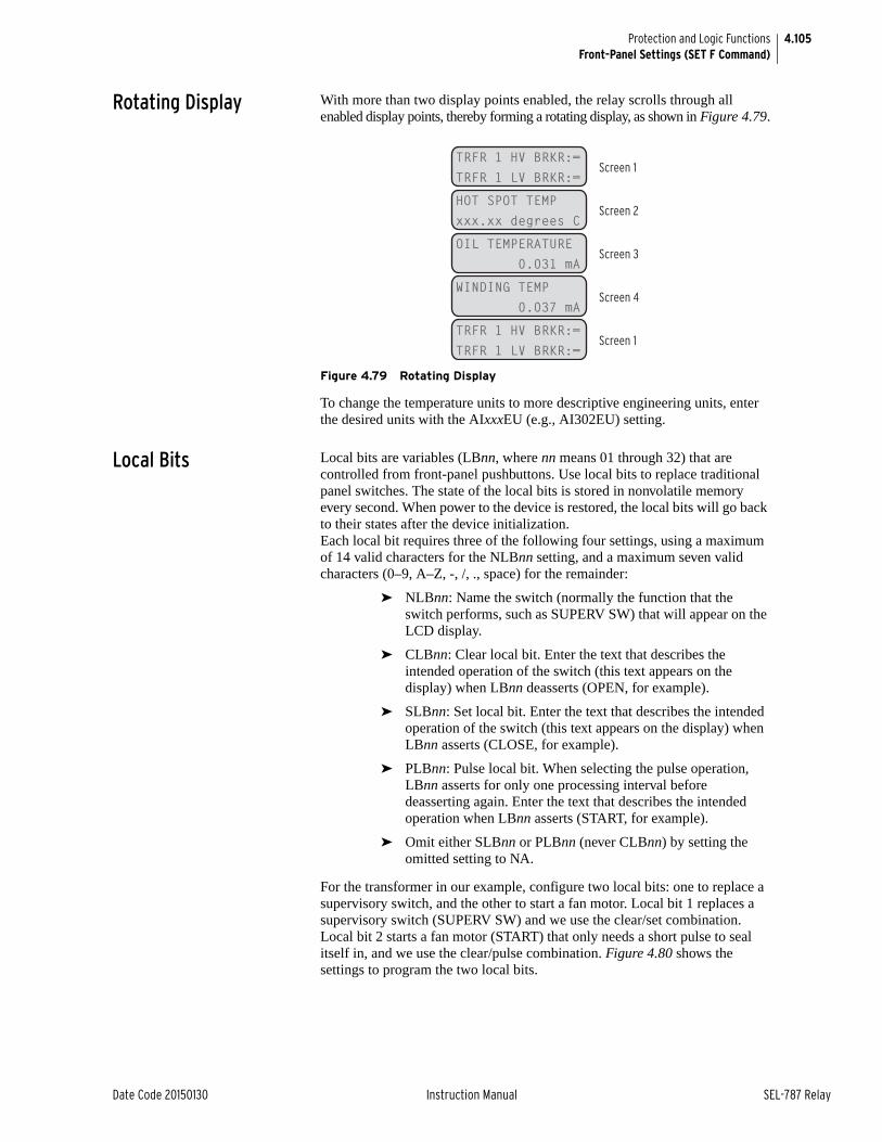
4.105
Date Code 20150130 Instruction Manual SEL-787 Relay
Protection and Logic FunctionsFront-Panel Settings (SET F Command)
Rotating Display With more than two display points enabled, the relay scrolls through all enabled display points, thereby forming a rotating display, as shown in Figure 4.79.
Figure 4.79 Rotating Display
To change the temperature units to more descriptive engineering units, enter the desired units with the AIxxxEU (e.g., AI302EU) setting.
Local Bits Local bits are variables (LBnn, where nn means 01 through 32) that are controlled from front-panel pushbuttons. Use local bits to replace traditional panel switches. The state of the local bits is stored in nonvolatile memory every second. When power to the device is restored, the local bits will go back to their states after the device initialization.Each local bit requires three of the following four settings, using a maximum of 14 valid characters for the NLBnn setting, and a maximum seven valid characters (0–9, A–Z, -, /, ., space) for the remainder:
➤ NLBnn: Name the switch (normally the function that the switch performs, such as SUPERV SW) that will appear on the LCD display.
➤ CLBnn: Clear local bit. Enter the text that describes the intended operation of the switch (this text appears on the display) when LBnn deasserts (OPEN, for example).
➤ SLBnn: Set local bit. Enter the text that describes the intended operation of the switch (this text appears on the display) when LBnn asserts (CLOSE, for example).
➤ PLBnn: Pulse local bit. When selecting the pulse operation, LBnn asserts for only one processing interval before deasserting again. Enter the text that describes the intended operation when LBnn asserts (START, for example).
➤ Omit either SLBnn or PLBnn (never CLBnn) by setting the omitted setting to NA.
For the transformer in our example, configure two local bits: one to replace a supervisory switch, and the other to start a fan motor. Local bit 1 replaces a supervisory switch (SUPERV SW) and we use the clear/set combination. Local bit 2 starts a fan motor (START) that only needs a short pulse to seal itself in, and we use the clear/pulse combination. Figure 4.80 shows the settings to program the two local bits.
TRFR 1 HV BRKR:=TRFR 1 LV BRKR:=
Screen 1
HOT SPOT TEMPxxx.xx degrees C
Screen 2
OIL TEMPERATURE 0.031 mA
Screen 3
WINDING TEMP 0.037 mA
Screen 4
TRFR 1 HV BRKR:=TRFR 1 LV BRKR:=
Screen 1
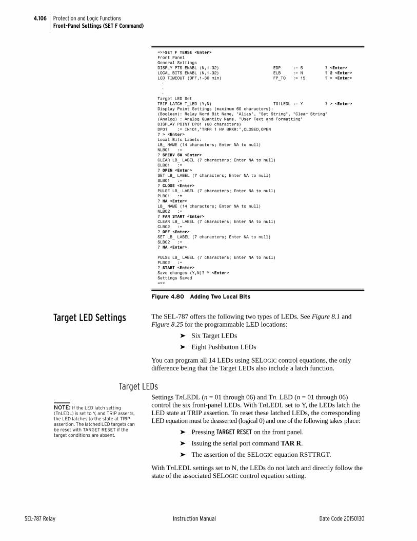
4.106
SEL-787 Relay Instruction Manual Date Code 20150130
Protection and Logic FunctionsFront-Panel Settings (SET F Command)
Target LED Settings The SEL-787 offers the following two types of LEDs. See Figure 8.1 and Figure 8.25 for the programmable LED locations:
➤ Six Target LEDs
➤ Eight Pushbutton LEDs
You can program all 14 LEDs using SELOGIC control equations, the only difference being that the Target LEDs also include a latch function.
Target LEDsSettings TnLEDL (n = 01 through 06) and Tn_LED (n = 01 through 06) control the six front-panel LEDs. With TnLEDL set to Y, the LEDs latch the LED state at TRIP assertion. To reset these latched LEDs, the corresponding LED equation must be deasserted (logical 0) and one of the following takes place:
➤ Pressing TARGET RESET on the front panel.
➤ Issuing the serial port command TAR R.
➤ The assertion of the SELOGIC equation RSTTRGT.
With TnLEDL settings set to N, the LEDs do not latch and directly follow the state of the associated SELOGIC control equation setting.
=>>SET F TERSE <Enter>Front PanelGeneral SettingsDISPLY PTS ENABL (N,1-32) EDP := 5 ? <Enter>LOCAL BITS ENABL (N,1-32) ELB := N ? 2 <Enter>LCD TIMEOUT (OFF,1-30 min) FP_TO := 15 ? > <Enter>•••
Target LED SetTRIP LATCH T_LED (Y,N) T01LEDL := Y ? > <Enter>Display Point Settings (maximum 60 characters):(Boolean): Relay Word Bit Name, "Alias", "Set String", "Clear String"(Analog) : Analog Quantity Name, "User Text and Formatting"DISPLAY POINT DP01 (60 characters)DP01 := IN101,"TRFR 1 HV BRKR:",CLOSED,OPEN? > <Enter>Local Bits Labels:LB_ NAME (14 characters; Enter NA to null)NLB01 :=? SPERV SW <Enter>CLEAR LB_ LABEL (7 characters; Enter NA to null)CLB01 :=? OPEN <Enter>SET LB_ LABEL (7 characters; Enter NA to null)SLB01 :=? CLOSE <Enter>PULSE LB_ LABEL (7 characters; Enter NA to null)PLB01 :=? NA <Enter>LB_ NAME (14 characters; Enter NA to null)NLB02 :=? FAN START <Enter>CLEAR LB_ LABEL (7 characters; Enter NA to null)CLB02 :=? OFF <Enter>SET LB_ LABEL (7 characters; Enter NA to null)SLB02 :=? NA <Enter>
PULSE LB_ LABEL (7 characters; Enter NA to null)PLB02 :=? START <Enter>Save changes (Y,N)? Y <Enter>Settings Saved=>>
Figure 4.80 Adding Two Local Bits
NOTE: If the LED latch setting (TnLEDL) is set to Y, and TRIP asserts, the LED latches to the state at TRIP assertion. The latched LED targets can be reset with TARGET RESET if the target conditions are absent.
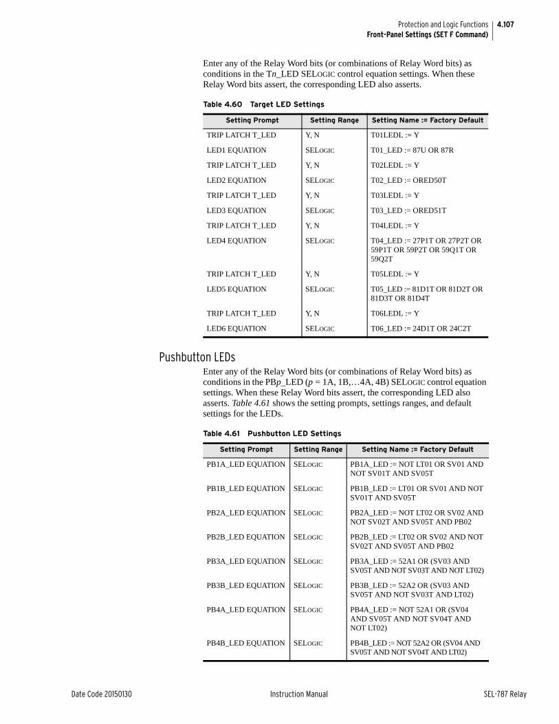
4.107
Date Code 20150130 Instruction Manual SEL-787 Relay
Protection and Logic FunctionsFront-Panel Settings (SET F Command)
Enter any of the Relay Word bits (or combinations of Relay Word bits) as conditions in the Tn_LED SELOGIC control equation settings. When these Relay Word bits assert, the corresponding LED also asserts.
Pushbutton LEDsEnter any of the Relay Word bits (or combinations of Relay Word bits) as conditions in the PBp_LED (p = 1A, 1B,…4A, 4B) SELOGIC control equation settings. When these Relay Word bits assert, the corresponding LED also asserts. Table 4.61 shows the setting prompts, settings ranges, and default settings for the LEDs.
Table 4.60 Target LED Settings
Setting Prompt Setting Range Setting Name := Factory Default
TRIP LATCH T_LED Y, N T01LEDL := Y
LED1 EQUATION SELOGIC T01_LED := 87U OR 87R
TRIP LATCH T_LED Y, N T02LEDL := Y
LED2 EQUATION SELOGIC T02_LED := ORED50T
TRIP LATCH T_LED Y, N T03LEDL := Y
LED3 EQUATION SELOGIC T03_LED := ORED51T
TRIP LATCH T_LED Y, N T04LEDL := Y
LED4 EQUATION SELOGIC T04_LED := 27P1T OR 27P2T OR 59P1T OR 59P2T OR 59Q1T OR 59Q2T
TRIP LATCH T_LED Y, N T05LEDL := Y
LED5 EQUATION SELOGIC T05_LED := 81D1T OR 81D2T OR 81D3T OR 81D4T
TRIP LATCH T_LED Y, N T06LEDL := Y
LED6 EQUATION SELOGIC T06_LED := 24D1T OR 24C2T
Table 4.61 Pushbutton LED Settings
Setting Prompt Setting Range Setting Name := Factory Default
PB1A_LED EQUATION SELOGIC PB1A_LED := NOT LT01 OR SV01 AND NOT SV01T AND SV05T
PB1B_LED EQUATION SELOGIC PB1B_LED := LT01 OR SV01 AND NOT SV01T AND SV05T
PB2A_LED EQUATION SELOGIC PB2A_LED := NOT LT02 OR SV02 AND NOT SV02T AND SV05T AND PB02
PB2B_LED EQUATION SELOGIC PB2B_LED := LT02 OR SV02 AND NOT SV02T AND SV05T AND PB02
PB3A_LED EQUATION SELOGIC PB3A_LED := 52A1 OR (SV03 AND SV05T AND NOT SV03T AND NOT LT02)
PB3B_LED EQUATION SELOGIC PB3B_LED := 52A2 OR (SV03 AND SV05T AND NOT SV03T AND LT02)
PB4A_LED EQUATION SELOGIC PB4A_LED := NOT 52A1 OR (SV04 AND SV05T AND NOT SV04T AND NOT LT02)
PB4B_LED EQUATION SELOGIC PB4B_LED := NOT 52A2 OR (SV04 AND SV05T AND NOT SV04T AND LT02)
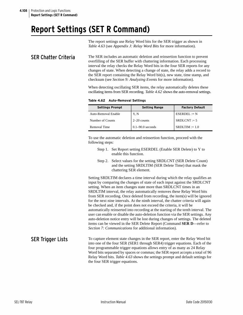
4.108
SEL-787 Relay Instruction Manual Date Code 20150130
Protection and Logic FunctionsReport Settings (SET R Command)
Report Settings (SET R Command)The report settings use Relay Word bits for the SER trigger as shown in Table 4.63 (see Appendix J: Relay Word Bits for more information).
SER Chatter Criteria The SER includes an automatic deletion and reinsertion function to prevent overfilling of the SER buffer with chattering information. Each processing interval the relay checks the Relay Word bits in the four SER reports for any changes of state. When detecting a change of state, the relay adds a record to the SER report containing the Relay Word bit(s), new state, time stamp, and checksum (see Section 9: Analyzing Events for more information).
When detecting oscillating SER items, the relay automatically deletes these oscillating items from SER recording. Table 4.62 shows the auto-removal settings.
To use the automatic deletion and reinsertion function, proceed with the following steps:
Step 1. Set Report setting ESERDEL (Enable SER Delete) to Y to enable this function.
Step 2. Select values for the setting SRDLCNT (SER Delete Count) and the setting SRDLTIM (SER Delete Time) that mask the chattering SER element.
Setting SRDLTIM declares a time interval during which the relay qualifies an input by comparing the changes of state of each input against the SRDLCNT setting. When an item changes state more than SRDLCNT times in an SRDLTIM interval, the relay automatically removes these Relay Word bits from SER recording. Once deleted from recording, the item(s) will be ignored for the next nine intervals. At the ninth interval, the chatter criteria will again be checked and, if the point does not exceed the criteria, it will be automatically reinserted into recording at the starting of the tenth interval. The user can enable or disable the auto-deletion function via the SER settings. Any auto-deletion notice entry will be lost during changes of settings. The deleted items can be viewed in the SER Delete Report (Command SER D—refer to Section 7: Communications for additional information).
SER Trigger Lists To capture element state changes in the SER report, enter the Relay Word bit into one of the four SER (SER1 through SER4) trigger equations. Each of the four programmable trigger equations allows entry of as many as 24 Relay Word bits separated by spaces or commas; the SER report accepts a total of 96 Relay Word bits. Table 4.63 shows the settings prompt and default settings for the four SER trigger equations.
Table 4.62 Auto-Removal Settings
Settings Prompt Setting Range Factory Default
Auto-Removal Enable Y, N ESERDEL := N
Number of Counts 2–20 counts SRDLCNT := 5
Removal Time 0.1–90.0 seconds SRDLTIM := 1.0
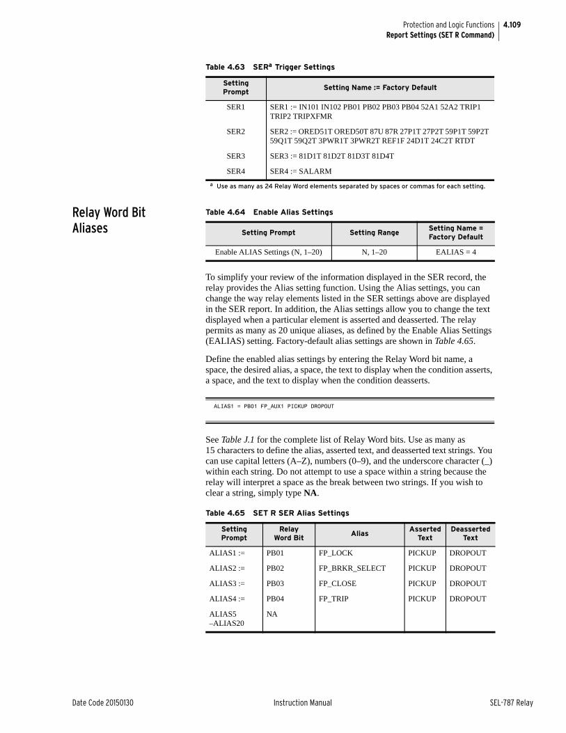
4.109
Date Code 20150130 Instruction Manual SEL-787 Relay
Protection and Logic FunctionsReport Settings (SET R Command)
Relay Word Bit Aliases
To simplify your review of the information displayed in the SER record, the relay provides the Alias setting function. Using the Alias settings, you can change the way relay elements listed in the SER settings above are displayed in the SER report. In addition, the Alias settings allow you to change the text displayed when a particular element is asserted and deasserted. The relay permits as many as 20 unique aliases, as defined by the Enable Alias Settings (EALIAS) setting. Factory-default alias settings are shown in Table 4.65.
Define the enabled alias settings by entering the Relay Word bit name, a space, the desired alias, a space, the text to display when the condition asserts, a space, and the text to display when the condition deasserts.
See Table J.1 for the complete list of Relay Word bits. Use as many as 15 characters to define the alias, asserted text, and deasserted text strings. You can use capital letters (A–Z), numbers (0–9), and the underscore character (_) within each string. Do not attempt to use a space within a string because the relay will interpret a space as the break between two strings. If you wish to clear a string, simply type NA.
Table 4.63 SERa Trigger Settings
a Use as many as 24 Relay Word elements separated by spaces or commas for each setting.
Setting Prompt
Setting Name := Factory Default
SER1 SER1 := IN101 IN102 PB01 PB02 PB03 PB04 52A1 52A2 TRIP1 TRIP2 TRIPXFMR
SER2 SER2 := ORED51T ORED50T 87U 87R 27P1T 27P2T 59P1T 59P2T 59Q1T 59Q2T 3PWR1T 3PWR2T REF1F 24D1T 24C2T RTDT
SER3 SER3 := 81D1T 81D2T 81D3T 81D4T
SER4 SER4 := SALARM
Table 4.64 Enable Alias Settings
Setting Prompt Setting RangeSetting Name = Factory Default
Enable ALIAS Settings (N, 1–20) N, 1–20 EALIAS = 4
ALIAS1 = PB01 FP_AUX1 PICKUP DROPOUT
Table 4.65 SET R SER Alias Settings
Setting Prompt
Relay Word Bit
AliasAsserted
TextDeasserted
Text
ALIAS1 := PB01 FP_LOCK PICKUP DROPOUT
ALIAS2 := PB02 FP_BRKR_SELECT PICKUP DROPOUT
ALIAS3 := PB03 FP_CLOSE PICKUP DROPOUT
ALIAS4 := PB04 FP_TRIP PICKUP DROPOUT
ALIAS5–ALIAS20
NA
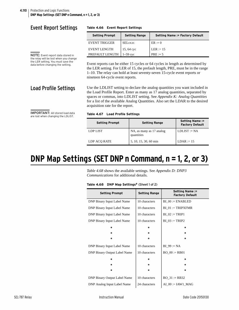
4.110
SEL-787 Relay Instruction Manual Date Code 20150130
Protection and Logic FunctionsDNP Map Settings (SET DNP n Command, n = 1, 2, or 3)
Event Report Settings
Event reports can be either 15 cycles or 64 cycles in length as determined by the LER setting. For LER of 15, the prefault length, PRE, must be in the range 1–10. The relay can hold at least seventy-seven 15-cycle event reports or nineteen 64-cycle event reports.
Load Profile Settings Use the LDLIST setting to declare the analog quantities you want included in the Load Profile Report. Enter as many as 17 analog quantities, separated by spaces or commas, into LDLIST setting. See Appendix K: Analog Quantities for a list of the available Analog Quantities. Also set the LDAR to the desired acquisition rate for the report.
IMPORTANT: All stored load data are lost when changing the LDLIST.
DNP Map Settings (SET DNP n Command, n = 1, 2, or 3)Table 4.68 shows the available settings. See Appendix D: DNP3 Communications for additional details.
Table 4.66 Event Report Settings
Setting Prompt Setting Range Setting Name := Factory Default
EVENT TRIGGER SELOGIC ER := 0
EVENT LENGTH 15, 64 cyc LER := 15
PREFAULT LENGTH 1–59 cyc PRE := 5NOTE: Event report data stored in the relay will be lost when you change the LER setting, You must save the data before changing the setting.
Table 4.67 Load Profile Settings
Setting Prompt Setting RangeSetting Name := Factory Default
LDP LIST NA, as many as 17 analog quantities
LDLIST := NA
LDP ACQ RATE 5, 10, 15, 30, 60 min LDAR := 15
Table 4.68 DNP Map Settingsa (Sheet 1 of 2)
Setting Prompt Setting RangeSetting Name := Factory Default
DNP Binary Input Label Name 10 characters BI_00 := ENABLED
DNP Binary Input Label Name 10 characters BI_01 := TRIPXFMR
DNP Binary Input Label Name 10 characters BI_02 := TRIP1
DNP Binary Input Label Name 10 characters BI_03 := TRIP2
•••
•••
•••
DNP Binary Input Label Name 10 characters BI_99 := NA
DNP Binary Output Label Name 10 characters BO_00 := RB01
•••
•••
•••
DNP Binary Output Label Name 10 characters BO_31 := RB32
DNP Analog Input Label Name 24 characters AI_00 := IAW1_MAG
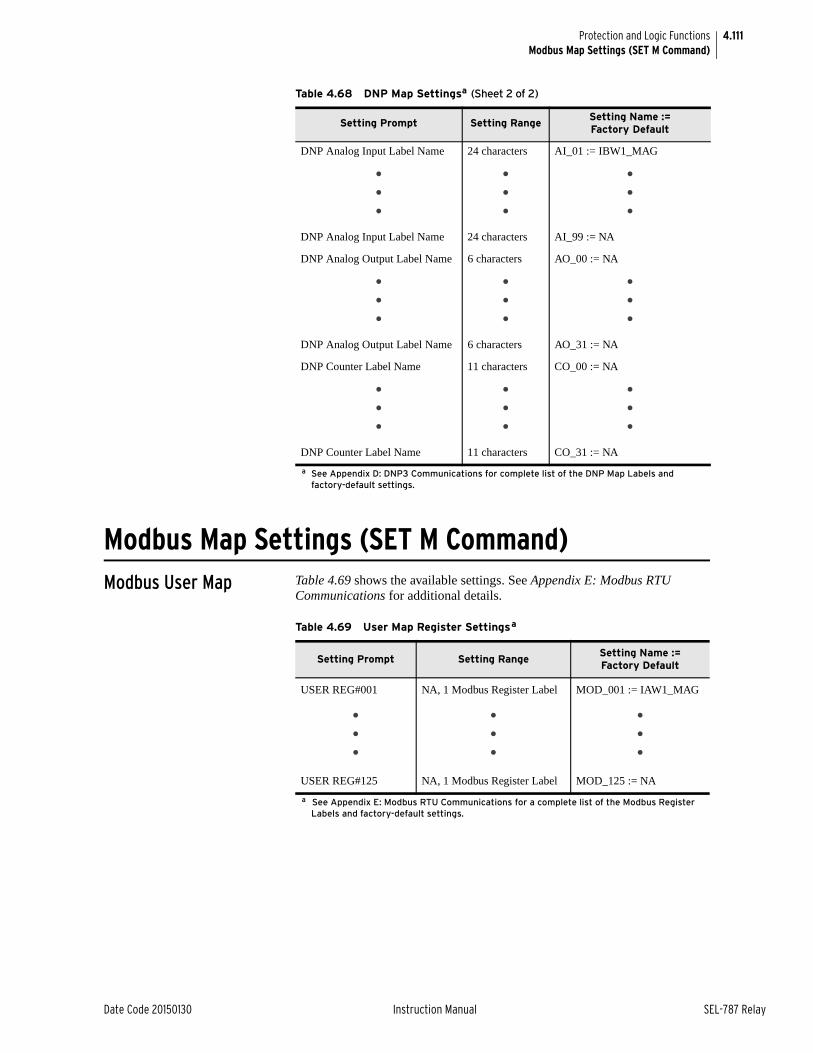
4.111
Date Code 20150130 Instruction Manual SEL-787 Relay
Protection and Logic FunctionsModbus Map Settings (SET M Command)
Modbus Map Settings (SET M Command)Modbus User Map Table 4.69 shows the available settings. See Appendix E: Modbus RTU
Communications for additional details.
DNP Analog Input Label Name 24 characters AI_01 := IBW1_MAG
•••
•••
•••
DNP Analog Input Label Name 24 characters AI_99 := NA
DNP Analog Output Label Name 6 characters AO_00 := NA
•••
•••
•••
DNP Analog Output Label Name 6 characters AO_31 := NA
DNP Counter Label Name 11 characters CO_00 := NA
•••
•••
•••
DNP Counter Label Name 11 characters CO_31 := NA
a See Appendix D: DNP3 Communications for complete list of the DNP Map Labels and factory-default settings.
Table 4.68 DNP Map Settingsa (Sheet 2 of 2)
Setting Prompt Setting RangeSetting Name := Factory Default
Table 4.69 User Map Register Settingsa
a See Appendix E: Modbus RTU Communications for a complete list of the Modbus Register Labels and factory-default settings.
Setting Prompt Setting RangeSetting Name :=Factory Default
USER REG#001 NA, 1 Modbus Register Label MOD_001 := IAW1_MAG
•••
•••
•••
USER REG#125 NA, 1 Modbus Register Label MOD_125 := NA

This page intentionally left blank
Date Code 20150130 Instruction Manual SEL-787 Relay
Section 5Metering and Monitoring
Instruction Manual
OverviewThe SEL-787 Transformer Protection Relay includes metering functions to display the present values of current, voltage (if included), analog inputs (if included), and RTD measurements (with the external SEL-2600 RTD Module or an internal RTD card).
The relay provides the following methods to read the present meter values:
➤ Front-panel rotating display
➤ Front-panel menu
➤ EIA-232 serial ports (using SEL ASCII text commands or ACSELERATOR QuickSet® SEL-5030 Software)
➤ Telnet via Ethernet port
➤ Modbus® via EIA-485 port or EIA-232 port
➤ Modbus TCP via Ethernet® port
➤ DNP3 Serial via EIA-232 port or EIA-485 port
➤ DNP3 LAN/WAN via Ethernet port
➤ DeviceNet port
➤ Analog outputs
➤ IEC 61850 via Ethernet port
➤ C37.118 Synchrophasor Protocol via serial port
Load monitoring and trending are possible using the Load Profile function. The relay automatically configures itself to save as many as 17 quantities (selected from the Analog Quantities) every 5, 10, 15, 30, or 60 minutes. The data are stored in nonvolatile memory. As many as 6500 time samples are stored.
The SEL-787 has a through-fault event monitoring function that gathers current level, duration and date/time for each through fault experienced by the transformer. The function calculates and tracks accumulated I2t through fault and alarms excess I2t over time. This monitor function can be used to schedule proactive transformer bank maintenance.
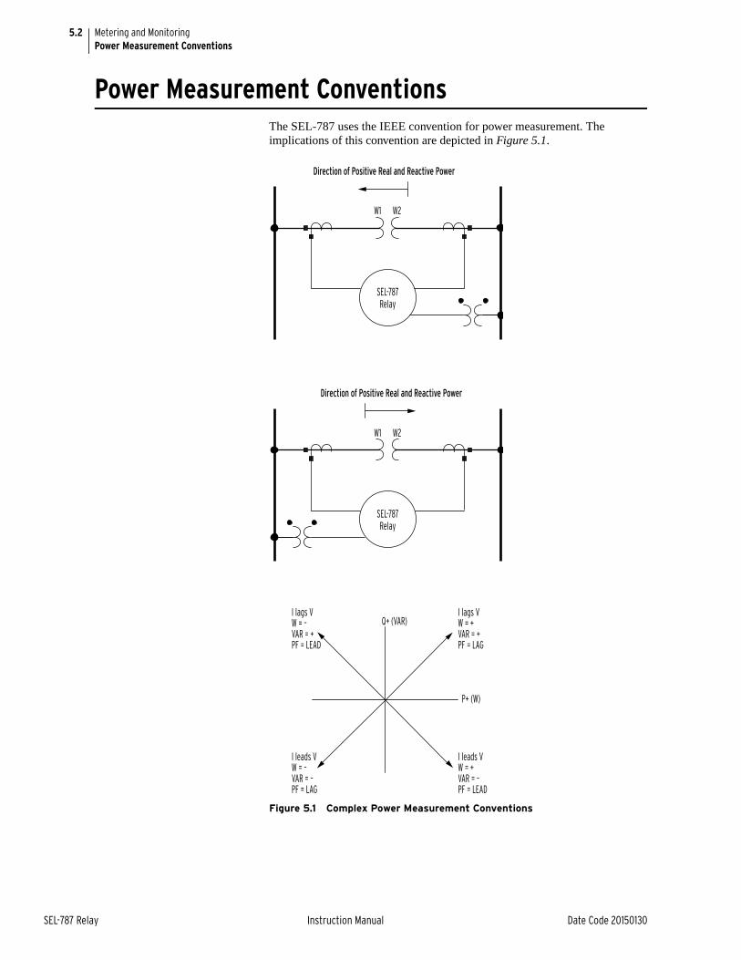
5.2
SEL-787 Relay Instruction Manual Date Code 20150130
Metering and MonitoringPower Measurement Conventions
Power Measurement ConventionsThe SEL-787 uses the IEEE convention for power measurement. The implications of this convention are depicted in Figure 5.1.
Figure 5.1 Complex Power Measurement Conventions
Q+ (VAR)
I leads VW = –VAR = –PF = LAG
I lags VW = –VAR = +PF = LEAD
P+ (W)
I leads VW = +VAR = –PF = LEAD
I lags VW = +VAR = +PF = LAG
SEL-787Relay
Direction of Positive Real and Reactive Power
W1 W2
SEL-787Relay
Direction of Positive Real and Reactive Power
W1 W2
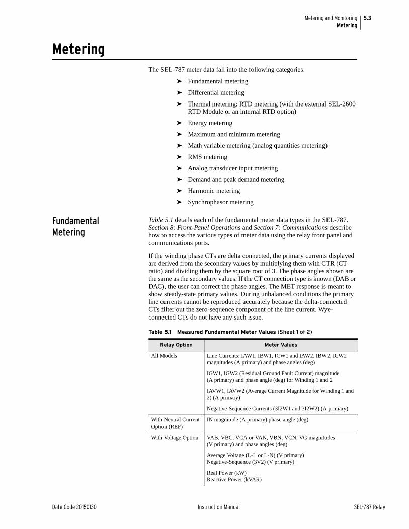
5.3
Date Code 20150130 Instruction Manual SEL-787 Relay
Metering and MonitoringMetering
MeteringThe SEL-787 meter data fall into the following categories:
➤ Fundamental metering
➤ Differential metering
➤ Thermal metering: RTD metering (with the external SEL-2600 RTD Module or an internal RTD option)
➤ Energy metering
➤ Maximum and minimum metering
➤ Math variable metering (analog quantities metering)
➤ RMS metering
➤ Analog transducer input metering
➤ Demand and peak demand metering
➤ Harmonic metering
➤ Synchrophasor metering
Fundamental Metering
Table 5.1 details each of the fundamental meter data types in the SEL-787. Section 8: Front-Panel Operations and Section 7: Communications describe how to access the various types of meter data using the relay front panel and communications ports.
If the winding phase CTs are delta connected, the primary currents displayed are derived from the secondary values by multiplying them with CTR (CT ratio) and dividing them by the square root of 3. The phase angles shown are the same as the secondary values. If the CT connection type is known (DAB or DAC), the user can correct the phase angles. The MET response is meant to show steady-state primary values. During unbalanced conditions the primary line currents cannot be reproduced accurately because the delta-connected CTs filter out the zero-sequence component of the line current. Wye-connected CTs do not have any such issue.
Table 5.1 Measured Fundamental Meter Values (Sheet 1 of 2)
Relay Option Meter Values
All Models Line Currents: IAW1, IBW1, ICW1 and IAW2, IBW2, ICW2 magnitudes (A primary) and phase angles (deg)
IGW1, IGW2 (Residual Ground Fault Current) magnitude (A primary) and phase angle (deg) for Winding 1 and 2
IAVW1, IAVW2 (Average Current Magnitude for Winding 1 and 2) (A primary)
Negative-Sequence Currents (3I2W1 and 3I2W2) (A primary)
With Neutral Current Option (REF)
IN magnitude (A primary) phase angle (deg)
With Voltage Option VAB, VBC, VCA or VAN, VBN, VCN, VG magnitudes (V primary) and phase angles (deg)
Average Voltage (L-L or L-N) (V primary)Negative-Sequence (3V2) (V primary)
Real Power (kW)Reactive Power (kVAR)
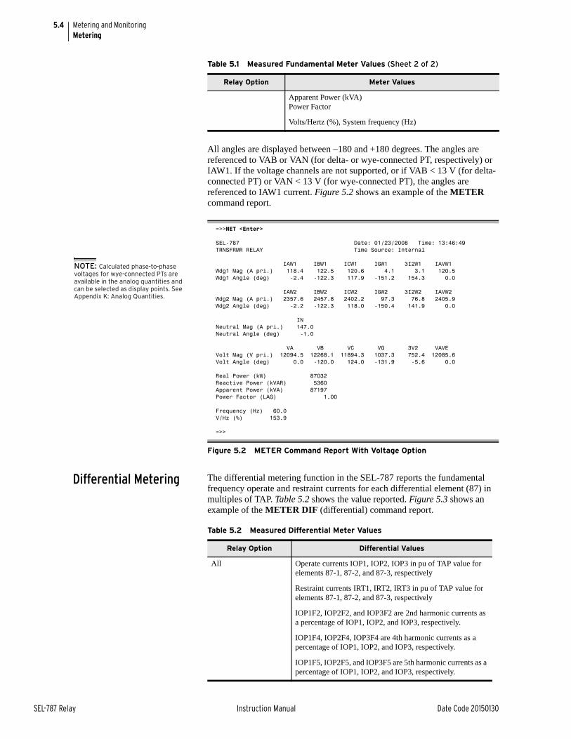
5.4
SEL-787 Relay Instruction Manual Date Code 20150130
Metering and MonitoringMetering
All angles are displayed between –180 and +180 degrees. The angles are referenced to VAB or VAN (for delta- or wye-connected PT, respectively) or IAW1. If the voltage channels are not supported, or if VAB < 13 V (for delta-connected PT) or VAN < 13 V (for wye-connected PT), the angles are referenced to IAW1 current. Figure 5.2 shows an example of the METER command report.
Differential Metering The differential metering function in the SEL-787 reports the fundamental frequency operate and restraint currents for each differential element (87) in multiples of TAP. Table 5.2 shows the value reported. Figure 5.3 shows an example of the METER DIF (differential) command report.
Apparent Power (kVA)Power Factor
Volts/Hertz (%), System frequency (Hz)
=>>MET <Enter>
SEL-787 Date: 01/23/2008 Time: 13:46:49TRNSFRMR RELAY Time Source: Internal
IAW1 IBW1 ICW1 IGW1 3I2W1 IAVW1Wdg1 Mag (A pri.) 118.4 122.5 120.6 4.1 3.1 120.5Wdg1 Angle (deg) -2.4 -122.3 117.9 -151.2 154.3 0.0
IAW2 IBW2 ICW2 IGW2 3I2W2 IAVW2Wdg2 Mag (A pri.) 2357.6 2457.8 2402.2 97.3 76.8 2405.9Wdg2 Angle (deg) -2.2 -122.3 118.0 -150.4 141.9 0.0
INNeutral Mag (A pri.) 147.0Neutral Angle (deg) -1.0
VA VB VC VG 3V2 VAVEVolt Mag (V pri.) 12094.5 12268.1 11894.3 1037.3 752.4 12085.6Volt Angle (deg) 0.0 -120.0 124.0 -131.9 -5.6 0.0
Real Power (kW) 87032Reactive Power (kVAR) 5360Apparent Power (kVA) 87197Power Factor (LAG) 1.00
Frequency (Hz) 60.0V/Hz (%) 153.9
=>>
Figure 5.2 METER Command Report With Voltage Option
Table 5.1 Measured Fundamental Meter Values (Sheet 2 of 2)
Relay Option Meter Values
NOTE: Calculated phase-to-phase voltages for wye-connected PTs are available in the analog quantities and can be selected as display points. See Appendix K: Analog Quantities.
Table 5.2 Measured Differential Meter Values
Relay Option Differential Values
All Operate currents IOP1, IOP2, IOP3 in pu of TAP value for elements 87-1, 87-2, and 87-3, respectively
Restraint currents IRT1, IRT2, IRT3 in pu of TAP value for elements 87-1, 87-2, and 87-3, respectively
IOP1F2, IOP2F2, and IOP3F2 are 2nd harmonic currents as a percentage of IOP1, IOP2, and IOP3, respectively.
IOP1F4, IOP2F4, IOP3F4 are 4th harmonic currents as a percentage of IOP1, IOP2, and IOP3, respectively.
IOP1F5, IOP2F5, and IOP3F5 are 5th harmonic currents as a percentage of IOP1, IOP2, and IOP3, respectively.
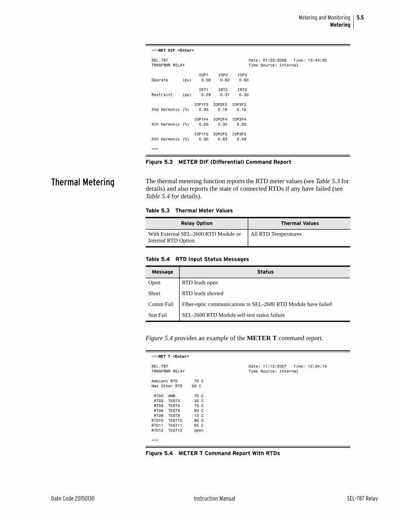
5.5
Date Code 20150130 Instruction Manual SEL-787 Relay
Metering and MonitoringMetering
Thermal Metering The thermal metering function reports the RTD meter values (see Table 5.3 for details) and also reports the state of connected RTDs if any have failed (see Table 5.4 for details).
Figure 5.4 provides an example of the METER T command report.
=>>MET DIF <Enter>
SEL-787 Date: 01/23/2008 Time: 13:44:35TRNSFRMR RELAY Time Source: Internal
IOP1 IOP2 IOP3Operate (pu) 0.59 0.62 0.60
IRT1 IRT2 IRT3Restraint (pu) 0.29 0.31 0.30
IOP1F2 IOP2F2 IOP3F22nd Harmonic (%) 0.33 0.16 0.16
IOP1F4 IOP2F4 IOP3F44th Harmonic (%) 0.50 0.32 0.33
IOP1F5 IOP2F5 IOP3F55th Harmonic (%) 0.50 0.63 0.49
=>>
Figure 5.3 METER DIF (Differential) Command Report
Table 5.3 Thermal Meter Values
Relay Option Thermal Values
With External SEL-2600 RTD Module or Internal RTD Option
All RTD Temperatures
Table 5.4 RTD Input Status Messages
Message Status
Open RTD leads open
Short RTD leads shorted
Comm Fail Fiber-optic communications to SEL-2600 RTD Module have failed
Stat Fail SEL-2600 RTD Module self-test status failure
=>>MET T <Enter>
SEL-787 Date: 11/12/2007 Time: 12:34:14TRNSFRMR RELAY Time Source: Internal
Ambient RTD 70 CMax Other RTD 95 C RTD2 AMB 70 C RTD3 TEST3 -30 C RTD5 TEST5 75 C RTD6 TEST6 90 C RTD8 TEST8 -10 CRTD10 TEST10 95 CRTD11 TEST11 65 CRTD12 TEST12 open
=>>
Figure 5.4 METER T Command Report With RTDs
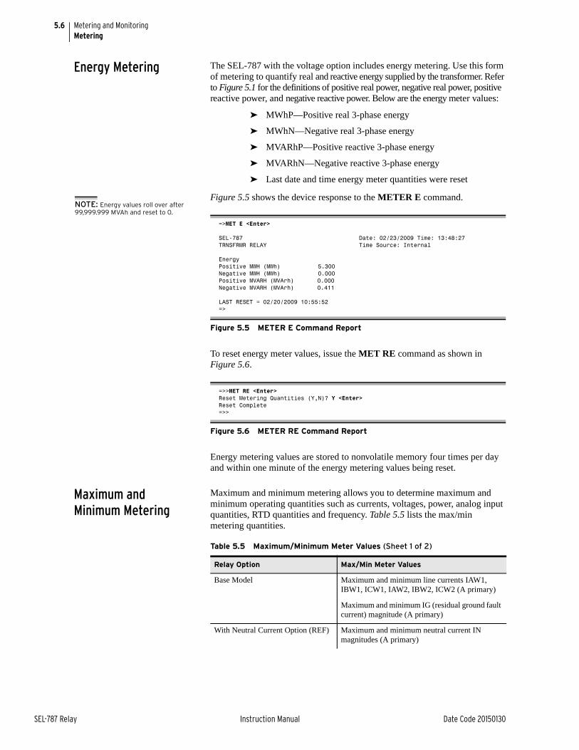
5.6
SEL-787 Relay Instruction Manual Date Code 20150130
Metering and MonitoringMetering
Energy Metering The SEL-787 with the voltage option includes energy metering. Use this form of metering to quantify real and reactive energy supplied by the transformer. Refer to Figure 5.1 for the definitions of positive real power, negative real power, positive reactive power, and negative reactive power. Below are the energy meter values:
➤ MWhP—Positive real 3-phase energy
➤ MWhN—Negative real 3-phase energy
➤ MVARhP—Positive reactive 3-phase energy
➤ MVARhN—Negative reactive 3-phase energy
➤ Last date and time energy meter quantities were reset
Figure 5.5 shows the device response to the METER E command.
To reset energy meter values, issue the MET RE command as shown in Figure 5.6.
Energy metering values are stored to nonvolatile memory four times per day and within one minute of the energy metering values being reset.
Maximum and Minimum Metering
Maximum and minimum metering allows you to determine maximum and minimum operating quantities such as currents, voltages, power, analog input quantities, RTD quantities and frequency. Table 5.5 lists the max/min metering quantities.
=>MET E <Enter>
SEL-787 Date: 02/23/2009 Time: 13:48:27TRNSFRMR RELAY Time Source: Internal
EnergyPositive MWH (MWh) 5.300Negative MWH (MWh) 0.000Positive MVARH (MVArh) 0.000Negative MVARH (MVArh) 0.411
LAST RESET = 02/20/2009 10:55:52=>
Figure 5.5 METER E Command Report
=>>MET RE <Enter>Reset Metering Quantities (Y,N)? Y <Enter>Reset Complete=>>
Figure 5.6 METER RE Command Report
NOTE: Energy values roll over after 99,999.999 MVAh and reset to 0.
Table 5.5 Maximum/Minimum Meter Values (Sheet 1 of 2)
Relay Option Max/Min Meter Values
Base Model Maximum and minimum line currents IAW1, IBW1, ICW1, IAW2, IBW2, ICW2 (A primary)
Maximum and minimum IG (residual ground fault current) magnitude (A primary)
With Neutral Current Option (REF) Maximum and minimum neutral current IN magnitudes (A primary)
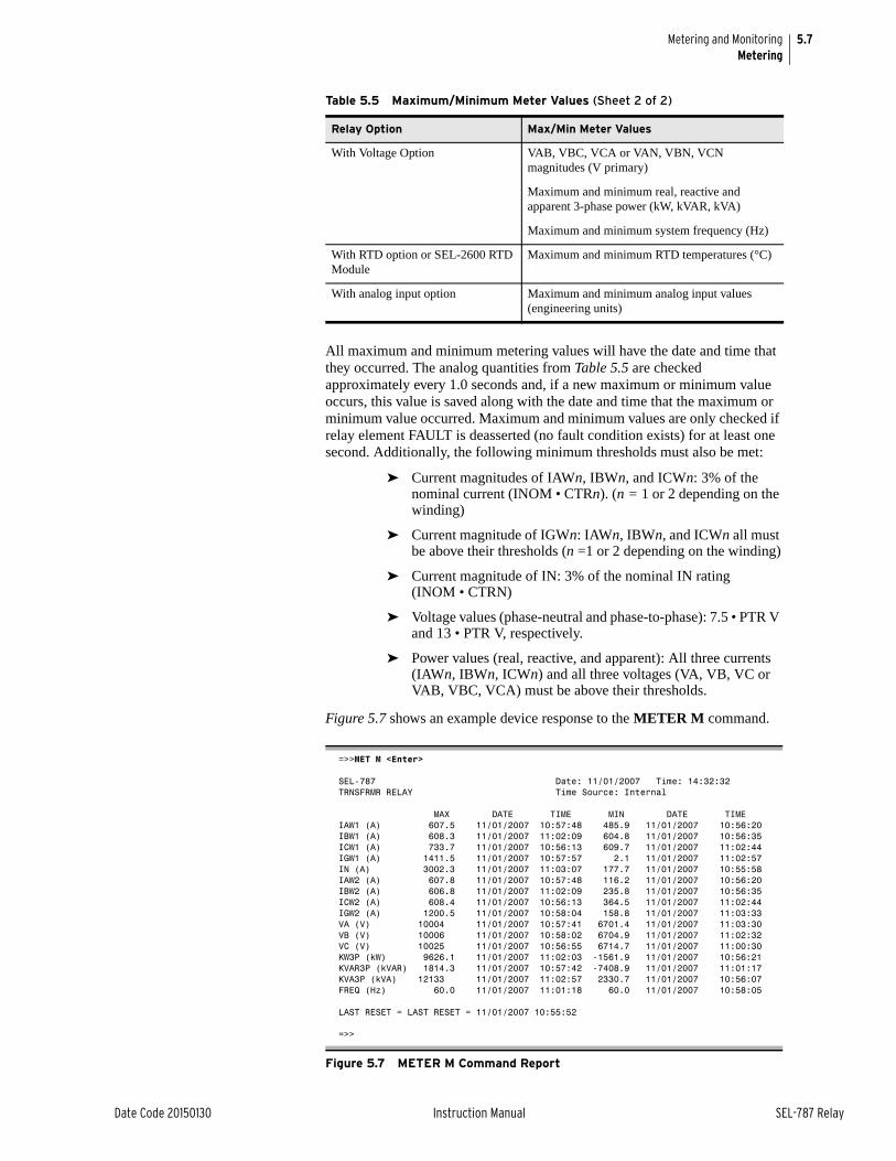
5.7
Date Code 20150130 Instruction Manual SEL-787 Relay
Metering and MonitoringMetering
All maximum and minimum metering values will have the date and time that they occurred. The analog quantities from Table 5.5 are checked approximately every 1.0 seconds and, if a new maximum or minimum value occurs, this value is saved along with the date and time that the maximum or minimum value occurred. Maximum and minimum values are only checked if relay element FAULT is deasserted (no fault condition exists) for at least one second. Additionally, the following minimum thresholds must also be met:
➤ Current magnitudes of IAWn, IBWn, and ICWn: 3% of the nominal current (INOM • CTRn). (n = 1 or 2 depending on the winding)
➤ Current magnitude of IGWn: IAWn, IBWn, and ICWn all must be above their thresholds (n =1 or 2 depending on the winding)
➤ Current magnitude of IN: 3% of the nominal IN rating (INOM • CTRN)
➤ Voltage values (phase-neutral and phase-to-phase): 7.5 • PTR V and 13 • PTR V, respectively.
➤ Power values (real, reactive, and apparent): All three currents (IAWn, IBWn, ICWn) and all three voltages (VA, VB, VC or VAB, VBC, VCA) must be above their thresholds.
Figure 5.7 shows an example device response to the METER M command.
With Voltage Option VAB, VBC, VCA or VAN, VBN, VCN magnitudes (V primary)
Maximum and minimum real, reactive and apparent 3-phase power (kW, kVAR, kVA)
Maximum and minimum system frequency (Hz)
With RTD option or SEL-2600 RTD Module
Maximum and minimum RTD temperatures (°C)
With analog input option Maximum and minimum analog input values (engineering units)
=>>MET M <Enter>
SEL-787 Date: 11/01/2007 Time: 14:32:32TRNSFRMR RELAY Time Source: Internal
MAX DATE TIME MIN DATE TIMEIAW1 (A) 607.5 11/01/2007 10:57:48 485.9 11/01/2007 10:56:20 IBW1 (A) 608.3 11/01/2007 11:02:09 604.8 11/01/2007 10:56:35ICW1 (A) 733.7 11/01/2007 10:56:13 609.7 11/01/2007 11:02:44IGW1 (A) 1411.5 11/01/2007 10:57:57 2.1 11/01/2007 11:02:57IN (A) 3002.3 11/01/2007 11:03:07 177.7 11/01/2007 10:55:58IAW2 (A) 607.8 11/01/2007 10:57:48 116.2 11/01/2007 10:56:20IBW2 (A) 606.8 11/01/2007 11:02:09 235.8 11/01/2007 10:56:35ICW2 (A) 608.4 11/01/2007 10:56:13 364.5 11/01/2007 11:02:44IGW2 (A) 1200.5 11/01/2007 10:58:04 158.8 11/01/2007 11:03:33VA (V) 10004 11/01/2007 10:57:41 6701.4 11/01/2007 11:03:30VB (V) 10006 11/01/2007 10:58:02 6704.9 11/01/2007 11:02:32VC (V) 10025 11/01/2007 10:56:55 6714.7 11/01/2007 11:00:30KW3P (kW) 9626.1 11/01/2007 11:02:03 -1561.9 11/01/2007 10:56:21KVAR3P (kVAR) 1814.3 11/01/2007 10:57:42 -7408.9 11/01/2007 11:01:17KVA3P (kVA) 12133 11/01/2007 11:02:57 2330.7 11/01/2007 10:56:07FREQ (Hz) 60.0 11/01/2007 11:01:18 60.0 11/01/2007 10:58:05
LAST RESET = LAST RESET = 11/01/2007 10:55:52
=>>
Figure 5.7 METER M Command Report
Table 5.5 Maximum/Minimum Meter Values (Sheet 2 of 2)
Relay Option Max/Min Meter Values
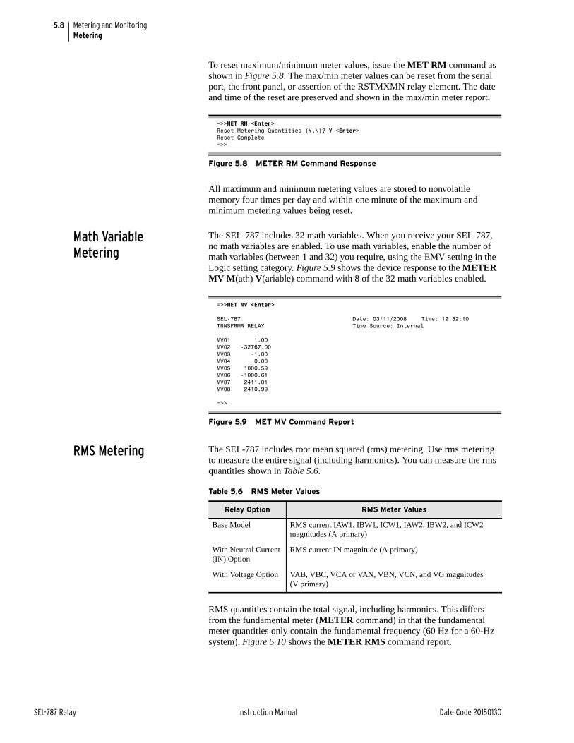
5.8
SEL-787 Relay Instruction Manual Date Code 20150130
Metering and MonitoringMetering
To reset maximum/minimum meter values, issue the MET RM command as shown in Figure 5.8. The max/min meter values can be reset from the serial port, the front panel, or assertion of the RSTMXMN relay element. The date and time of the reset are preserved and shown in the max/min meter report.
All maximum and minimum metering values are stored to nonvolatile memory four times per day and within one minute of the maximum and minimum metering values being reset.
Math Variable Metering
The SEL-787 includes 32 math variables. When you receive your SEL-787, no math variables are enabled. To use math variables, enable the number of math variables (between 1 and 32) you require, using the EMV setting in the Logic setting category. Figure 5.9 shows the device response to the METER MV M(ath) V(ariable) command with 8 of the 32 math variables enabled.
RMS Metering The SEL-787 includes root mean squared (rms) metering. Use rms metering to measure the entire signal (including harmonics). You can measure the rms quantities shown in Table 5.6.
RMS quantities contain the total signal, including harmonics. This differs from the fundamental meter (METER command) in that the fundamental meter quantities only contain the fundamental frequency (60 Hz for a 60-Hz system). Figure 5.10 shows the METER RMS command report.
=>>MET RM <Enter>Reset Metering Quantities (Y,N)? Y <Enter>Reset Complete=>>
Figure 5.8 METER RM Command Response
=>>MET MV <Enter>
SEL-787 Date: 03/11/2008 Time: 12:32:10 TRNSFRMR RELAY Time Source: Internal MV01 1.00MV02 -32767.00MV03 -1.00MV04 0.00MV05 1000.59MV06 -1000.61MV07 2411.01MV08 2410.99
=>>
Figure 5.9 MET MV Command Report
Table 5.6 RMS Meter Values
Relay Option RMS Meter Values
Base Model RMS current IAW1, IBW1, ICW1, IAW2, IBW2, and ICW2 magnitudes (A primary)
With Neutral Current (IN) Option
RMS current IN magnitude (A primary)
With Voltage Option VAB, VBC, VCA or VAN, VBN, VCN, and VG magnitudes (V primary)

5.9
Date Code 20150130 Instruction Manual SEL-787 Relay
Metering and MonitoringMetering
Analog Input Metering
The SEL-787 can monitor analog (transducer) quantities that it is measuring if equipped with optional analog inputs. Analog input metering shows transducer values from standard voltage and current transducers. These values can then be used for monitoring automation and control applications.
Through the global settings, you can set each type of analog input to the type of transducer that drives that analog input. You also set the range of the transducer output. Analog inputs can accept both current and voltage transducer outputs. Ranges for the current transducers are ±20 mA and ranges for the voltage transducers are ±10 V. You also set the corresponding output of the analog inputs in engineering units. See Section 4: Protection and Logic Functions for an explanation of how to set up analog inputs for reading transducers. Figure 5.11 shows an example of analog input metering.
Demand Metering The SEL-787 offers the choice between two types of demand metering, settable with the enable setting:
EDEM = THM (Thermal Demand Metering)or
EDEM = ROL (Rolling Demand Metering)
The relay provides demand (METER DE command) and peak demand (METER PE command) metering for the winding selected (Winding 1 or Winding 2). Table 5.7 shows the values reported. Figure 5.12 provides an example of the METER DE (Demand) command report and Figure 5.13 provides an example of the METER PE (Peak Demand) command report. Refer to Demand Metering on page 4.62 for detailed descriptions and settings selection.
=>MET RMS <Enter>
SEL-787 Date: 01/23/2008 Time: 13:44:57TRNSFRMR RELAY Time Source: Internal
IAW1 IBW1 ICW1RMS (A pri.) 118.0 122.5 120.7
IAW2 IBW2 ICW2RMS (A pri.) 2351.7 2461.3 2401.1
INRMS (A pri.) 146.6
VAB VBC VCARMS (V pri.) 12090 11893 21180
=>
Figure 5.10 METER RMS Command Report
=>MET AI <Enter>
SEL-787 Date: 01/23/2008 Time: 13:44:44TRNSFRMR RELAY Time Source: Internal
Input Card 3AI301 (mA) -0.008AI302 (mA) -0.007AI303 (mA) -0.001AI304 (mA) -0.006
=>
Figure 5.11 METER AI Command Report
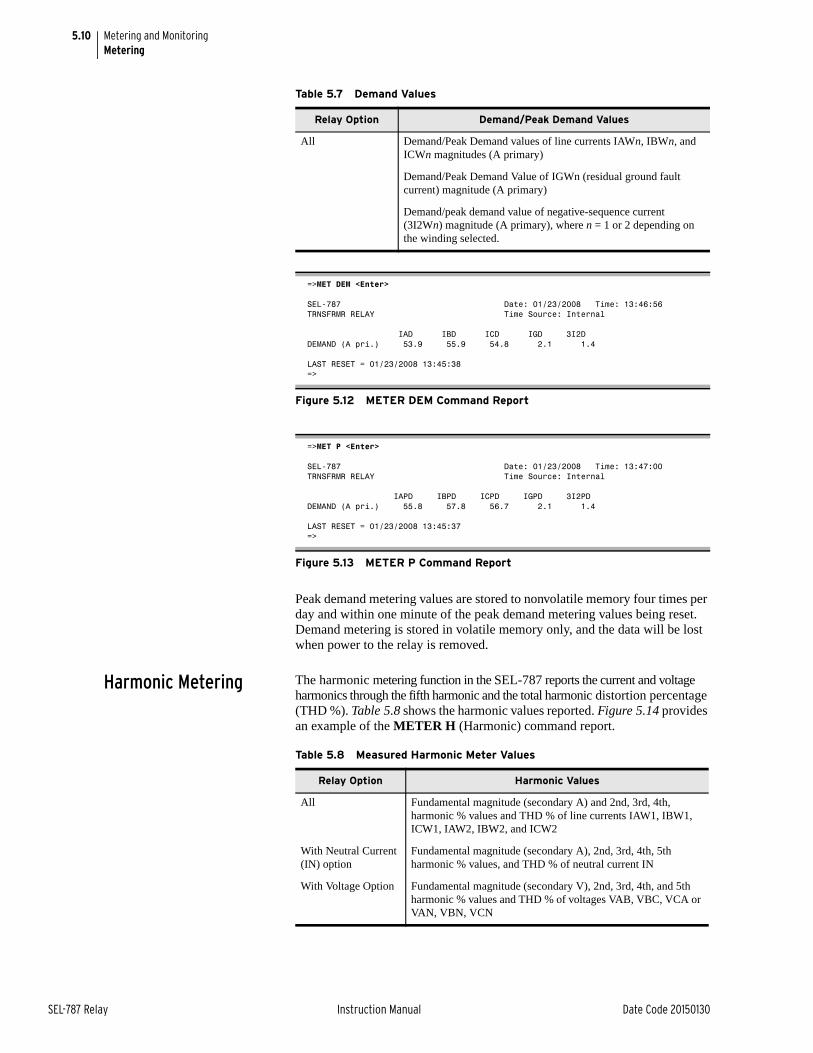
5.10
SEL-787 Relay Instruction Manual Date Code 20150130
Metering and MonitoringMetering
Peak demand metering values are stored to nonvolatile memory four times per day and within one minute of the peak demand metering values being reset. Demand metering is stored in volatile memory only, and the data will be lost when power to the relay is removed.
Harmonic Metering The harmonic metering function in the SEL-787 reports the current and voltage harmonics through the fifth harmonic and the total harmonic distortion percentage (THD %). Table 5.8 shows the harmonic values reported. Figure 5.14 provides an example of the METER H (Harmonic) command report.
Table 5.7 Demand Values
Relay Option Demand/Peak Demand Values
All Demand/Peak Demand values of line currents IAWn, IBWn, and ICWn magnitudes (A primary)
Demand/Peak Demand Value of IGWn (residual ground fault current) magnitude (A primary)
Demand/peak demand value of negative-sequence current (3I2Wn) magnitude (A primary), where n = 1 or 2 depending on the winding selected.
=>MET DEM <Enter>
SEL-787 Date: 01/23/2008 Time: 13:46:56TRNSFRMR RELAY Time Source: Internal
IAD IBD ICD IGD 3I2DDEMAND (A pri.) 53.9 55.9 54.8 2.1 1.4
LAST RESET = 01/23/2008 13:45:38=>
Figure 5.12 METER DEM Command Report
=>MET P <Enter>
SEL-787 Date: 01/23/2008 Time: 13:47:00TRNSFRMR RELAY Time Source: Internal
IAPD IBPD ICPD IGPD 3I2PDDEMAND (A pri.) 55.8 57.8 56.7 2.1 1.4
LAST RESET = 01/23/2008 13:45:37=>
Figure 5.13 METER P Command Report
Table 5.8 Measured Harmonic Meter Values
Relay Option Harmonic Values
All Fundamental magnitude (secondary A) and 2nd, 3rd, 4th, harmonic % values and THD % of line currents IAW1, IBW1, ICW1, IAW2, IBW2, and ICW2
With Neutral Current (IN) option
Fundamental magnitude (secondary A), 2nd, 3rd, 4th, 5th harmonic % values, and THD % of neutral current IN
With Voltage Option Fundamental magnitude (secondary V), 2nd, 3rd, 4th, and 5th harmonic % values and THD % of voltages VAB, VBC, VCA or VAN, VBN, VCN
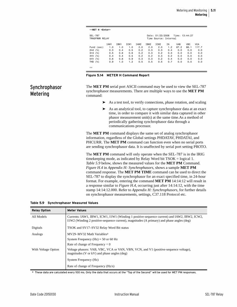
5.11
Date Code 20150130 Instruction Manual SEL-787 Relay
Metering and MonitoringMetering
Synchrophasor Metering
The MET PM serial port ASCII command may be used to view the SEL-787 synchrophasor measurements. There are multiple ways to use the MET PM command:
➤ As a test tool, to verify connections, phase rotation, and scaling
➤ As an analytical tool, to capture synchrophasor data at an exact time, in order to compare it with similar data captured in other phasor measurement unit(s) at the same time.As a method of periodically gathering synchrophasor data through a communications processor.
The MET PM command displays the same set of analog synchrophasor information, regardless of the Global settings PHDATAV, PHDATAI, and PHCURR. The MET PM command can function even when no serial ports are sending synchrophasor data. It is unaffected by serial port setting PROTO.
The MET PM command will only operate when the SEL-787 is in the IRIG timekeeping mode, as indicated by Relay Word bit TSOK = logical 1. Table 5.9 below, shows the measured values for the MET PM Command. Figure H.4 in Appendix H: Synchrophasors, shows a sample MET PM command response. The MET PM TIME command can be used to direct the SEL-787 to display the synchrophasor for an exact specified time, in 24-hour format. For example, entering the command MET PM 14:14:12 will result in a response similar to Figure H.4, occurring just after 14:14:12, with the time stamp 14:14:12.000. Refer to Appendix H: Synchrophasors, for further details on synchrophasor measurements, settings, C37.118 Protocol etc.
=>MET H <Enter>
SEL-787 Date: 01/23/2008 Time: 13:44:27TRNSFRMR RELAY Time Source: Internal
IAW1 IBW1 ICW1 IAW2 IBW2 ICW2 IN VAB VBC VCAFund (sec) 1.0 1.0 1.0 2.0 2.0 2.0 1.2 67.2 66.1 117.72nd (%) 0.3 0.4 0.5 0.2 0.3 0.3 0.4 0.0 0.0 0.03rd (%) 0.5 0.6 0.6 0.2 0.3 0.2 0.3 0.0 0.0 0.04th (%) 0.4 0.4 0.5 0.2 0.2 0.3 0.2 0.0 0.0 0.05th (%) 0.6 0.6 0.9 0.3 0.3 0.2 0.4 0.0 0.0 0.0THD (%) 0.9 1.0 1.2 0.5 0.5 0.5 0.7 0.0 0.0 0.0
=>
Figure 5.14 METER H Command Report
Table 5.9 Synchrophasor Measured Values
Relay Option Meter Values
All Models Currents: IAW1, IBW1, ICW1, I1W1 (Winding 1 positive-sequence current) and IAW2, IBW2, ICW2, I1W2 (Winding 2 positive-sequence current), magnitudes (A primary) and phase angles (deg)
Digitals TSOK and SV17–SV32 Relay Word Bit status
Analogs MV29–MV32 Math Variablesa
System Frequency (Hz) = 50 or 60 Hz
Rate of change of Frequency = 0
With Voltage Option Voltage phasors: VAB, VBC, VCA or VAN, VBN, VCN, and V1 (positive-sequence voltage), magnitudes (V or kV) and phase angles (deg)
System Frequency (Hz)
Rate of change of Frequency (Hz/s)
a These data are calculated every 100 ms. Only the data that occurs at the “Top of the Second” will be used for MET PM responses.
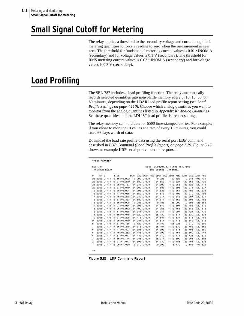
5.12
SEL-787 Relay Instruction Manual Date Code 20150130
Metering and MonitoringSmall Signal Cutoff for Metering
Small Signal Cutoff for Metering The relay applies a threshold to the secondary voltage and current magnitude metering quantities to force a reading to zero when the measurement is near zero. The threshold for fundamental metering current values is 0.01 • INOM A (secondary) and for voltage values is 0.1 V (secondary). The threshold for RMS metering current values is 0.03 • INOM A (secondary) and for voltage values is 0.3 V (secondary).
Load ProfilingThe SEL-787 includes a load profiling function. The relay automatically records selected quantities into nonvolatile memory every 5, 10, 15, 30, or 60 minutes, depending on the LDAR load profile report setting (see Load Profile Settings on page 4.110). Choose which analog quantities you want to monitor from the analog quantities listed in Appendix K: Analog Quantities. Set these quantities into the LDLIST load profile list report setting.
The relay memory can hold data for 6500 time-stamped entries. For example, if you chose to monitor 10 values at a rate of every 15 minutes, you could store 66 days worth of data.
Download the load rate profile data using the serial port LDP command described in LDP Command (Load Profile Report) on page 7.29. Figure 5.15 shows an example LDP serial port command response.
=>LDP <Enter>
SEL-787 Date: 2008/01/17 Time: 18:07:05TRNSFRMR RELAY Time Source: Internal
# DATE TIME IAW1_MAG IAW1_ANG IBW1_MAG IBW1_ANG ICW1_MAG ICW1_ANG23 2008/01/14 16:16:40.992 0.099 0.000 0.225 -52.125 0.344 -108.43522 2008/01/14 16:21:40.270 124.580 0.000 124.853 -119.627 123.668 120.42621 2008/01/14 16:26:40.157 124.346 0.000 124.902 -119.358 123.626 120.71120 2008/01/14 16:31:40.019 124.309 0.000 124.886 -119.598 123.973 120.57719 2008/01/14 16:36:40.024 124.293 0.000 124.836 -119.361 123.403 120.63118 2008/01/14 16:41:40.056 124.559 0.000 124.813 -119.709 123.970 120.49317 2008/01/14 16:46:40.275 124.249 0.000 124.774 -119.646 123.907 120.57416 2008/01/14 16:51:40.333 124.589 0.000 124.671 -119.569 123.603 120.48315 2008/01/14 16:56:40.908 0.088 0.000 0.188 45.000 0.395 -26.56514 2008/01/15 17:01:40.934 124.293 0.000 124.842 -119.504 123.485 120.61913 2008/01/15 17:06:40.972 124.490 0.000 124.758 -119.463 123.546 120.51812 2008/01/15 17:11:40.038 124.341 0.000 124.741 -119.297 123.424 120.77911 2008/01/16 17:16:40.045 124.320 0.000 125.130 -119.517 123.630 120.62310 2008/01/16 17:21:40.295 124.476 0.000 124.687 -119.537 123.518 120.4559 2008/01/16 17:26:40.070 124.284 0.000 124.874 -119.413 123.649 120.8188 2008/01/16 17:31:40.168 0.129 0.000 0.182 106.928 0.210 49.3997 2008/01/17 17:36:40.215 124.313 0.000 125.154 -119.530 123.752 120.6626 2008/01/17 17:41:40.803 124.383 0.000 124.992 -119.613 123.796 120.5505 2008/01/17 17:46:40.282 124.446 0.000 124.799 -119.464 123.600 120.4444 2008/01/17 17:51:40.077 124.432 0.000 124.710 -119.774 123.728 120.3793 2008/01/17 17:56:40.114 124.288 0.000 125.274 -119.590 123.905 120.6052 2008/01/17 18:01:41.047 124.392 0.000 124.730 -119.483 123.404 120.5761 2008/01/17 18:06:41.020 0.210 0.000 0.099 -8.130 0.182 -57.529
=>
Figure 5.15 LDP Command Report
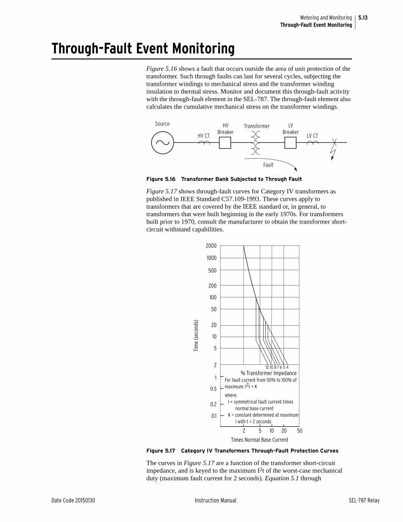
5.13
Date Code 20150130 Instruction Manual SEL-787 Relay
Metering and MonitoringThrough-Fault Event Monitoring
Through-Fault Event MonitoringFigure 5.16 shows a fault that occurs outside the area of unit protection of the transformer. Such through faults can last for several cycles, subjecting the transformer windings to mechanical stress and the transformer winding insulation to thermal stress. Monitor and document this through-fault activity with the through-fault element in the SEL-787. The through-fault element also calculates the cumulative mechanical stress on the transformer windings.
Figure 5.16 Transformer Bank Subjected to Through Fault
Figure 5.17 shows through-fault curves for Category IV transformers as published in IEEE Standard C57.109-1993. These curves apply to transformers that are covered by the IEEE standard or, in general, to transformers that were built beginning in the early 1970s. For transformers built prior to 1970, consult the manufacturer to obtain the transformer short-circuit withstand capabilities.
Figure 5.17 Category IV Transformers Through-Fault Protection Curves
The curves in Figure 5.17 are a function of the transformer short-circuit impedance, and is keyed to the maximum I2t of the worst-case mechanical duty (maximum fault current for 2 seconds). Equation 5.1 through
Source
HV CT
HVBreaker
Transformer LVBreaker
LV CT
Fault
% Transformer Impedance
Tim
e (s
econ
ds)
2000
1000
500
200
100
50
20
10
5
2
1
0.5
0.2
0.1
Times Normal Base Current
2 105 5020
12 10 8 7 6 5 4
For fault current from 50% to 100% of maximum: I2t = K
where:I = symmetrical fault current times
normal base currentK = constant determined at maximum
I with t = 2 seconds
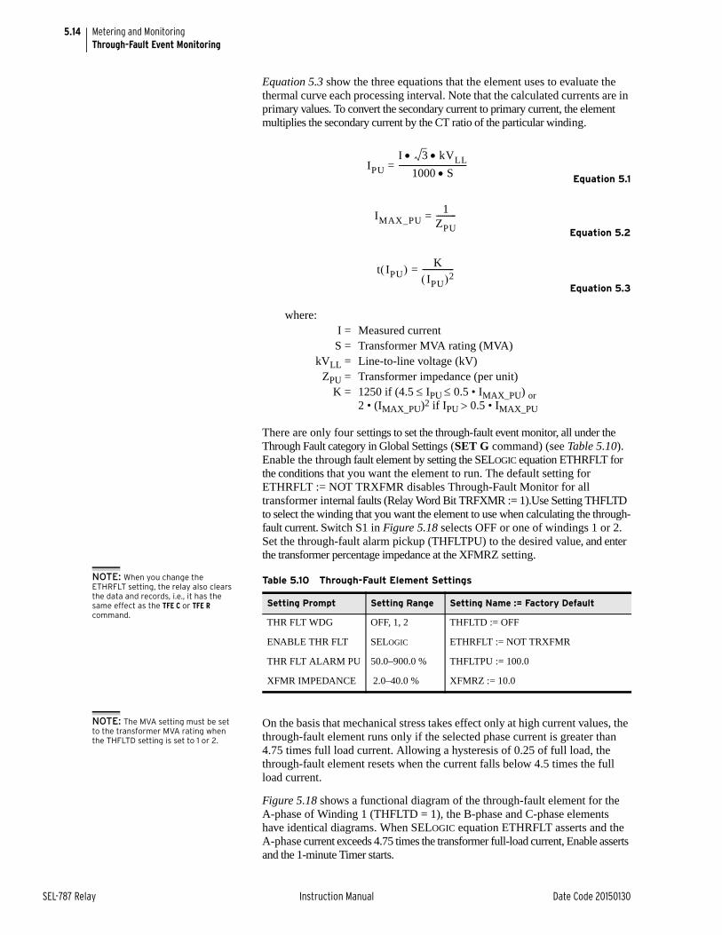
5.14
SEL-787 Relay Instruction Manual Date Code 20150130
Metering and MonitoringThrough-Fault Event Monitoring
Equation 5.3 show the three equations that the element uses to evaluate the thermal curve each processing interval. Note that the calculated currents are in primary values. To convert the secondary current to primary current, the element multiplies the secondary current by the CT ratio of the particular winding.
Equation 5.1
Equation 5.2
Equation 5.3
There are only four settings to set the through-fault event monitor, all under the Through Fault category in Global Settings (SET G command) (see Table 5.10). Enable the through fault element by setting the SELOGIC equation ETHRFLT for the conditions that you want the element to run. The default setting for ETHRFLT := NOT TRXFMR disables Through-Fault Monitor for all transformer internal faults (Relay Word Bit TRFXMR := 1).Use Setting THFLTD to select the winding that you want the element to use when calculating the through-fault current. Switch S1 in Figure 5.18 selects OFF or one of windings 1 or 2. Set the through-fault alarm pickup (THFLTPU) to the desired value, and enter the transformer percentage impedance at the XFMRZ setting.
NOTE: When you change the ETHRFLT setting, the relay also clears the data and records, i.e., it has the same effect as the TFE C or TFE R command.
NOTE: The MVA setting must be set to the transformer MVA rating when the THFLTD setting is set to 1 or 2.
On the basis that mechanical stress takes effect only at high current values, the through-fault element runs only if the selected phase current is greater than 4.75 times full load current. Allowing a hysteresis of 0.25 of full load, the through-fault element resets when the current falls below 4.5 times the full load current.
Figure 5.18 shows a functional diagram of the through-fault element for the A-phase of Winding 1 (THFLTD = 1), the B-phase and C-phase elements have identical diagrams. When SELOGIC equation ETHRFLT asserts and the A-phase current exceeds 4.75 times the transformer full-load current, Enable asserts and the 1-minute Timer starts.
where:I = Measured currentS = Transformer MVA rating (MVA)
kVLL = Line-to-line voltage (kV)ZPU = Transformer impedance (per unit)
K = 1250 if (4.5 IPU 0.5 • IMAX_PU) or2 • (IMAX_PU)2 if IPU 0.5 • IMAX_PU
IPU = I 3 kVLL
1000 S----------------------------------
IMAX_PU = 1
ZPU----------
t IPU = K
IPU 2----------------
Table 5.10 Through-Fault Element Settings
Setting Prompt Setting Range Setting Name := Factory Default
THR FLT WDG OFF, 1, 2 THFLTD := OFF
ENABLE THR FLT SELOGIC ETHRFLT := NOT TRXFMR
THR FLT ALARM PU 50.0–900.0 % THFLTPU := 100.0
XFMR IMPEDANCE 2.0–40.0 % XFMRZ := 10.0
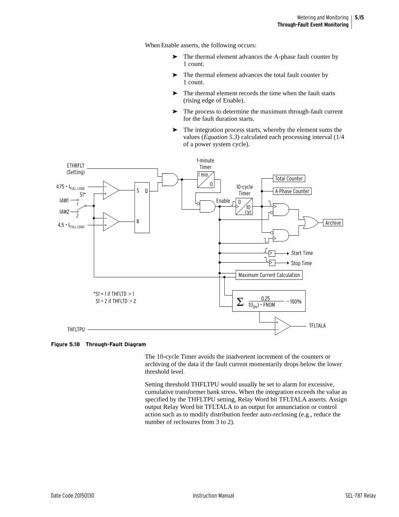
5.15
Date Code 20150130 Instruction Manual SEL-787 Relay
Metering and MonitoringThrough-Fault Event Monitoring
When Enable asserts, the following occurs:
➤ The thermal element advances the A-phase fault counter by 1 count.
➤ The thermal element advances the total fault counter by 1 count.
➤ The thermal element records the time when the fault starts (rising edge of Enable).
➤ The process to determine the maximum through-fault current for the fault duration starts.
➤ The integration process starts, whereby the element sums the values (Equation 5.3) calculated each processing interval (1/4 of a power system cycle).
Figure 5.18 Through-Fault Diagram
The 10-cycle Timer avoids the inadvertent increment of the counters or archiving of the data if the fault current momentarily drops below the lower threshold level.
Setting threshold THFLTPU would usually be set to alarm for excessive, cumulative transformer bank stress. When the integration exceeds the value as specified by the THFLTPU setting, Relay Word bit TFLTALA asserts. Assign output Relay Word bit TFLTALA to an output for annunciation or control action such as to modify distribution feeder auto-reclosing (e.g., reduce the number of reclosures from 3 to 2).
THFLTPU
ETHRFLT(Setting)
4.75 • IFULL LOAD
4.5 • IFULL LOAD
IAW1S1*
S Q
R
0
1 min
1-minuteTimer
Enable
10-cycleTimer
010
cyc
Total Counter
A-Phase Counter
Archive
Start Time
Stop Time
Maximum Current Calculation
TFLTALA
0.25t(Ipu) • FNOM • 100%
1
2
Σ
IAW2
*S1 = 1 if THFLTD := 1S1 = 2 if THFLTD := 2
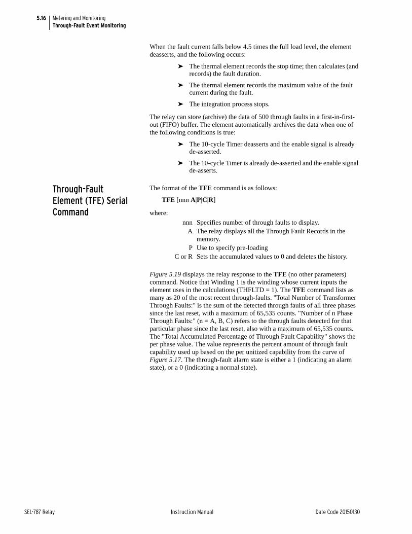
5.16
SEL-787 Relay Instruction Manual Date Code 20150130
Metering and MonitoringThrough-Fault Event Monitoring
When the fault current falls below 4.5 times the full load level, the element deasserts, and the following occurs:
➤ The thermal element records the stop time; then calculates (and records) the fault duration.
➤ The thermal element records the maximum value of the fault current during the fault.
➤ The integration process stops.
The relay can store (archive) the data of 500 through faults in a first-in-first-out (FIFO) buffer. The element automatically archives the data when one of the following conditions is true:
➤ The 10-cycle Timer deasserts and the enable signal is already de-asserted.
➤ The 10-cycle Timer is already de-asserted and the enable signal de-asserts.
Through-Fault Element (TFE) Serial Command
The format of the TFE command is as follows:
TFE [nnn A|P|C|R]
where:
Figure 5.19 displays the relay response to the TFE (no other parameters) command. Notice that Winding 1 is the winding whose current inputs the element uses in the calculations (THFLTD = 1). The TFE command lists as many as 20 of the most recent through-faults. "Total Number of Transformer Through Faults:" is the sum of the detected through faults of all three phases since the last reset, with a maximum of 65,535 counts. "Number of n Phase Through Faults:" (n = A, B, C) refers to the through faults detected for that particular phase since the last reset, also with a maximum of 65,535 counts. The "Total Accumulated Percentage of Through Fault Capability" shows the per phase value. The value represents the percent amount of through fault capability used up based on the per unitized capability from the curve of Figure 5.17. The through-fault alarm state is either a 1 (indicating an alarm state), or a 0 (indicating a normal state).
nnn Specifies number of through faults to display.A The relay displays all the Through Fault Records in the
memory.P Use to specify pre-loading
C or R Sets the accumulated values to 0 and deletes the history.
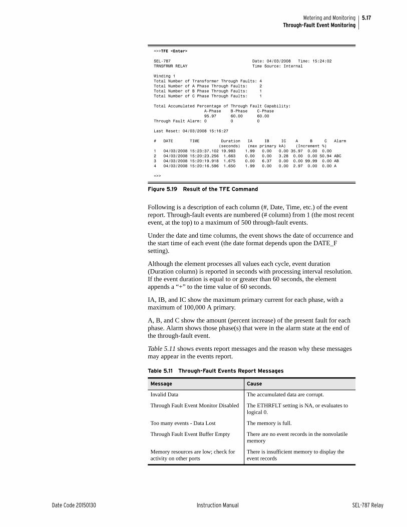
5.17
Date Code 20150130 Instruction Manual SEL-787 Relay
Metering and MonitoringThrough-Fault Event Monitoring
Following is a description of each column (#, Date, Time, etc.) of the event report. Through-fault events are numbered (# column) from 1 (the most recent event, at the top) to a maximum of 500 through-fault events.
Under the date and time columns, the event shows the date of occurrence and the start time of each event (the date format depends upon the DATE_F setting).
Although the element processes all values each cycle, event duration (Duration column) is reported in seconds with processing interval resolution. If the event duration is equal to or greater than 60 seconds, the element appends a “+” to the time value of 60 seconds.
IA, IB, and IC show the maximum primary current for each phase, with a maximum of 100,000 A primary.
A, B, and C show the amount (percent increase) of the present fault for each phase. Alarm shows those phase(s) that were in the alarm state at the end of the through-fault event.
Table 5.11 shows events report messages and the reason why these messages may appear in the events report.
=>>TFE <Enter>
SEL-787 Date: 04/03/2008 Time: 15:24:02TRNSFRMR RELAY Time Source: Internal
Winding 1Total Number of Transformer Through Faults: 4Total Number of A Phase Through Faults: 2Total Number of B Phase Through Faults: 1Total Number of C Phase Through Faults: 1
Total Accumulated Percentage of Through Fault Capability: A-Phase B-Phase C-Phase 95.97 60.00 60.00Through Fault Alarm: 0 0 0
Last Reset: 04/03/2008 15:16:27
# DATE TIME Duration IA IB IC A B C Alarm (seconds) (max primary kA) (Increment %)1 04/03/2008 15:23:37.102 19.983 1.99 0.00 0.00 35.97 0.00 0.002 04/03/2008 15:20:23.256 1.663 0.00 0.00 3.28 0.00 0.00 50.94 ABC3 04/03/2008 15:20:19.918 1.675 0.00 6.37 0.00 0.00 99.99 0.00 AB4 04/03/2008 15:20:16.596 1.650 1.99 0.00 0.00 2.97 0.00 0.00 A
=>>
Figure 5.19 Result of the TFE Command
Table 5.11 Through-Fault Events Report Messages
Message Cause
Invalid Data The accumulated data are corrupt.
Through Fault Event Monitor Disabled The ETHRFLT setting is NA, or evaluates to logical 0.
Too many events - Data Lost The memory is full.
Through Fault Event Buffer Empty There are no event records in the nonvolatile memory
Memory resources are low; check for activity on other ports
There is insufficient memory to display the event records
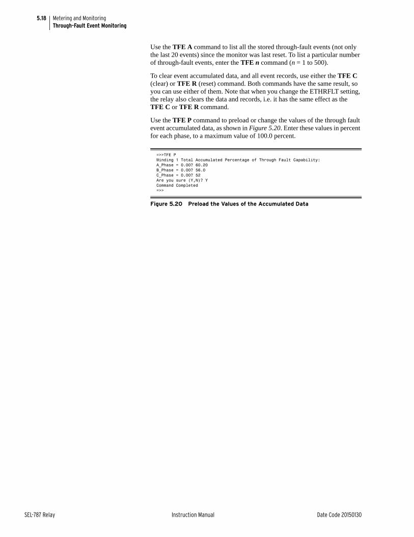
5.18
SEL-787 Relay Instruction Manual Date Code 20150130
Metering and MonitoringThrough-Fault Event Monitoring
Use the TFE A command to list all the stored through-fault events (not only the last 20 events) since the monitor was last reset. To list a particular number of through-fault events, enter the TFE n command (n = 1 to 500).
To clear event accumulated data, and all event records, use either the TFE C (clear) or TFE R (reset) command. Both commands have the same result, so you can use either of them. Note that when you change the ETHRFLT setting, the relay also clears the data and records, i.e. it has the same effect as the TFE C or TFE R command.
Use the TFE P command to preload or change the values of the through fault event accumulated data, as shown in Figure 5.20. Enter these values in percent for each phase, to a maximum value of 100.0 percent.
=>>TFE PWinding 1 Total Accumulated Percentage of Through Fault Capability:A_Phase = 0.00? 60.20B_Phase = 0.00? 56.0C_Phase = 0.00? 52Are you sure (Y,N)? YCommand Completed=>>
Figure 5.20 Preload the Values of the Accumulated Data
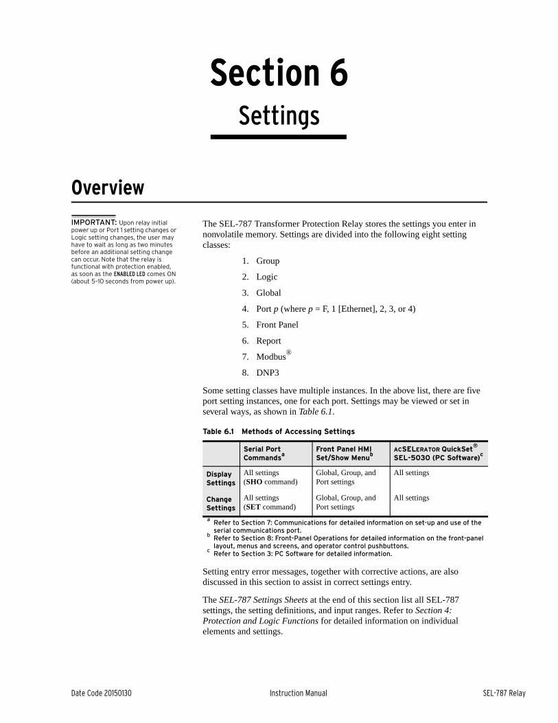
Date Code 20150130 Instruction Manual SEL-787 Relay
Section 6Settings
Instruction Manual
Overview
IMPORTANT: Upon relay initial power up or Port 1 setting changes or Logic setting changes, the user may have to wait as long as two minutes before an additional setting change can occur. Note that the relay is functional with protection enabled, as soon as the ENABLED LED comes ON (about 5–10 seconds from power up).
The SEL-787 Transformer Protection Relay stores the settings you enter in nonvolatile memory. Settings are divided into the following eight setting classes:
1. Group
2. Logic
3. Global
4. Port p (where p = F, 1 [Ethernet], 2, 3, or 4)
5. Front Panel
6. Report
7. Modbus®
8. DNP3
Some setting classes have multiple instances. In the above list, there are five port setting instances, one for each port. Settings may be viewed or set in several ways, as shown in Table 6.1.
Setting entry error messages, together with corrective actions, are also discussed in this section to assist in correct settings entry.
The SEL-787 Settings Sheets at the end of this section list all SEL-787 settings, the setting definitions, and input ranges. Refer to Section 4: Protection and Logic Functions for detailed information on individual elements and settings.
Table 6.1 Methods of Accessing Settings
Serial Port Commands
a
a Refer to Section 7: Communications for detailed information on set-up and use of the serial communications port.
Front Panel HMI Set/Show Menu
b
b Refer to Section 8: Front-Panel Operations for detailed information on the front-panel layout, menus and screens, and operator control pushbuttons.
ACSELERATOR QuickSet®
SEL-5030 (PC Software)c
c Refer to Section 3: PC Software for detailed information.
Display Settings
All settings(SHO command)
Global, Group, and Port settings
All settings
Change Settings
All settings(SET command)
Global, Group, and Port settings
All settings

6.2
SEL-787 Relay Instruction Manual Date Code 20150130
SettingsView/Change Settings With Front Panel
View/Change Settings With Front PanelYou can use the pushbuttons on the front panel to view/change settings. Section 8: Front-Panel Operations presents the operating details of the front panel.
Enter the front-panel menu by pushing the ESC pushbutton. It will display the following message:
Scroll down the menu by using the Down Arrow pushbutton until the display shows the following message:
The cursor (underline) should be on the Set/Show command. Enter the Set/Show command by pushing the ENT pushbutton. The display shows the following message:
Enter the underlined RELAY message with the ENT pushbutton, and the relay will present you with the RELAY settings as listed in the SEL-787 Settings Sheets. Use the Up Arrow, Down Arrow, Left Arrow, and Right Arrow pushbuttons to scroll through the relay settings. View and change the settings according to your needs by selecting and editing them. After viewing or changing the RELAY settings, press the ESC pushbutton until the following message appears:
Select and enter the appropriate command by pushing the ENT pushbutton. Select Yes to save the settings changes and No to discard the changes.
Figure 6.1 shows a front-panel menu navigation example for the relay to enter the PHASE PT RATIO, PTR setting.
MAINMeter
ControlSet/Show
SET/SHOWGlobal
Save Changes?Yes NoNOTE: Each SEL-787 is shipped with
default factory settings. Calculate the settings for your application to ensure secure and dependable protection. Document the settings on the SEL-787 Settings Sheets at the end of this section before entering new settings in the relay.
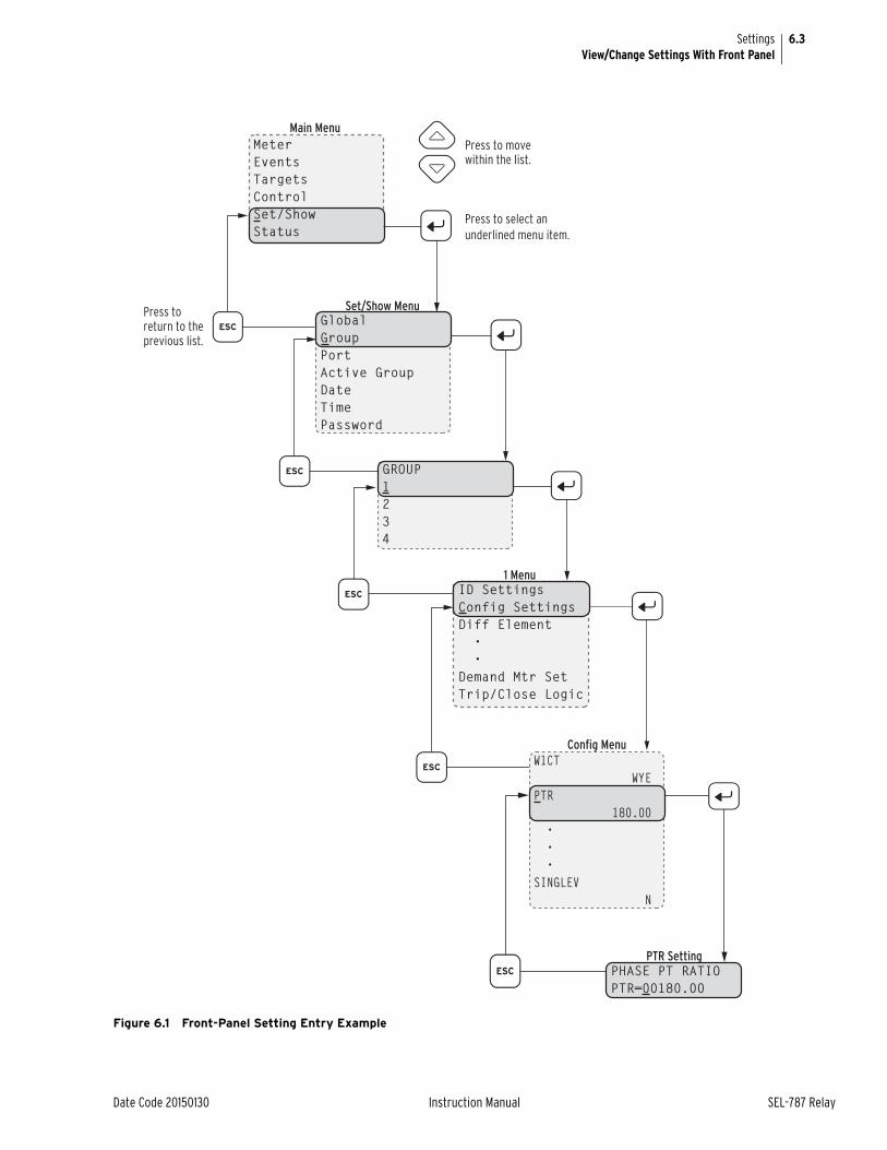
6.3
Date Code 20150130 Instruction Manual SEL-787 Relay
SettingsView/Change Settings With Front Panel
Figure 6.1 Front-Panel Setting Entry Example
Main Menu
MeterEventsTargetsControlSet/ShowStatus
Press to move within the list.
Press to return to the previous list.
Press to select an underlined menu item.
GROUP1234
Set/Show Menu
GlobalGroupPortActive GroupDateTimePassword
1 Menu
ID SettingsConfig SettingsDiff Element • •Demand Mtr SetTrip/Close Logic
PTR Setting
PHASE PT RATIOPTR=00180.00
Config Menu
W1CT WYEPTR 180.00 • • •SINGLEV N
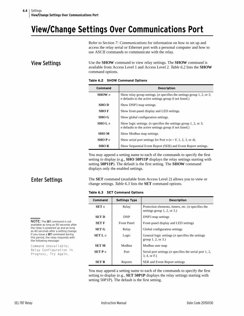
6.4
SEL-787 Relay Instruction Manual Date Code 20150130
SettingsView/Change Settings Over Communications Port
View/Change Settings Over Communications Port Refer to Section 7: Communications for information on how to set up and access the relay serial or Ethernet port with a personal computer and how to use ASCII commands to communicate with the relay.
View Settings Use the SHOW command to view relay settings. The SHOW command is available from Access Level 1 and Access Level 2. Table 6.2 lists the SHOW command options.
You may append a setting name to each of the commands to specify the first setting to display (e.g., SHO 50P11P displays the relay settings starting with setting 50P11P). The default is the first setting. The SHOW command displays only the enabled settings.
Enter Settings The SET command (available from Access Level 2) allows you to view or change settings. Table 6.3 lists the SET command options.
You may append a setting name to each of the commands to specify the first setting to display (e.g., SET 50P1P displays the relay settings starting with setting 50P1P). The default is the first setting.
Table 6.2 SHOW Command Options
Command Description
SHOW n Show relay group settings. (n specifies the settings group 1, 2, or 3; n defaults to the active settings group if not listed.)
SHO D Show DNP3 map settings.
SHO F Show front-panel display and LED settings.
SHO G Show global configuration settings.
SHO L n Show logic settings. (n specifies the settings group 1, 2, or 3; n defaults to the active settings group if not listed.)
SHO M Show Modbus map settings.
SHO P n Show serial port settings for Port n (n = F, 1, 2, 3, or 4).
SHO R Show Sequential Event Report (SER) and Event Report settings.
Table 6.3 SET Command Options
Command Settings Type Description
SET n Relay Protection elements, timers, etc. (n specifies the settings group 1, 2, or 3.)
SET D DNP DNP3 map settings
SET F Front Panel Front-panel display and LED settings
SET G Relay Global configuration settings
SET L n Logic General logic settings (n specifies the settings group 1, 2, or 3.)
SET M Modbus Modbus user map
SET P n Port Serial port settings (n specifies the serial port 1, 2, 3, 4, or F.)
SET R Reports SER and Event Report settings
NOTE: The SET command is not available as long as 90 seconds after the relay is powered up and as long as 40 seconds after a setting change. If you issue a SET command during this period, the relay responds with the following message:
Command Unavailable; Relay Configuration in Progress, Try Again.
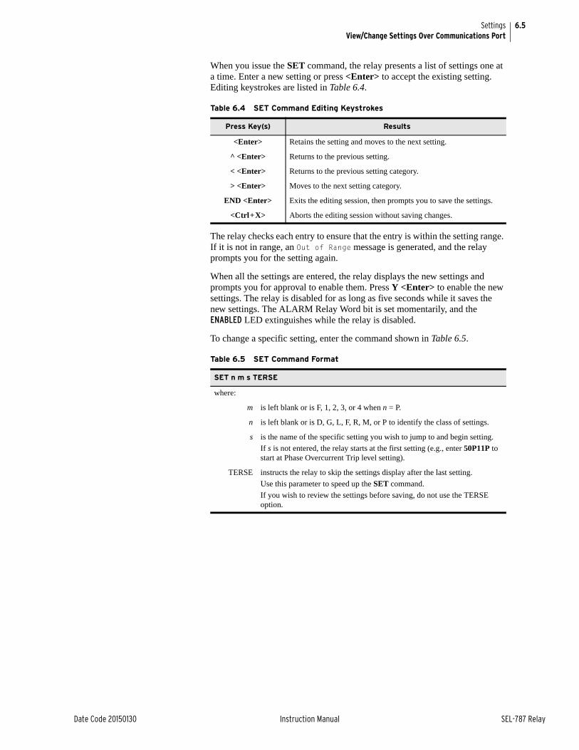
6.5
Date Code 20150130 Instruction Manual SEL-787 Relay
SettingsView/Change Settings Over Communications Port
When you issue the SET command, the relay presents a list of settings one at a time. Enter a new setting or press <Enter> to accept the existing setting. Editing keystrokes are listed in Table 6.4.
The relay checks each entry to ensure that the entry is within the setting range. If it is not in range, an Out of Range message is generated, and the relay prompts you for the setting again.
When all the settings are entered, the relay displays the new settings and prompts you for approval to enable them. Press Y <Enter> to enable the new settings. The relay is disabled for as long as five seconds while it saves the new settings. The ALARM Relay Word bit is set momentarily, and the ENABLED LED extinguishes while the relay is disabled.
To change a specific setting, enter the command shown in Table 6.5.
Table 6.4 SET Command Editing Keystrokes
Press Key(s) Results
<Enter> Retains the setting and moves to the next setting.
^ <Enter> Returns to the previous setting.
< <Enter> Returns to the previous setting category.
> <Enter> Moves to the next setting category.
END <Enter> Exits the editing session, then prompts you to save the settings.
<Ctrl+X> Aborts the editing session without saving changes.
Table 6.5 SET Command Format
SET n m s TERSE
where:
m is left blank or is F, 1, 2, 3, or 4 when n = P.
n is left blank or is D, G, L, F, R, M, or P to identify the class of settings.
s is the name of the specific setting you wish to jump to and begin setting.
If s is not entered, the relay starts at the first setting (e.g., enter 50P11P to start at Phase Overcurrent Trip level setting).
TERSE instructs the relay to skip the settings display after the last setting.
Use this parameter to speed up the SET command.
If you wish to review the settings before saving, do not use the TERSE option.
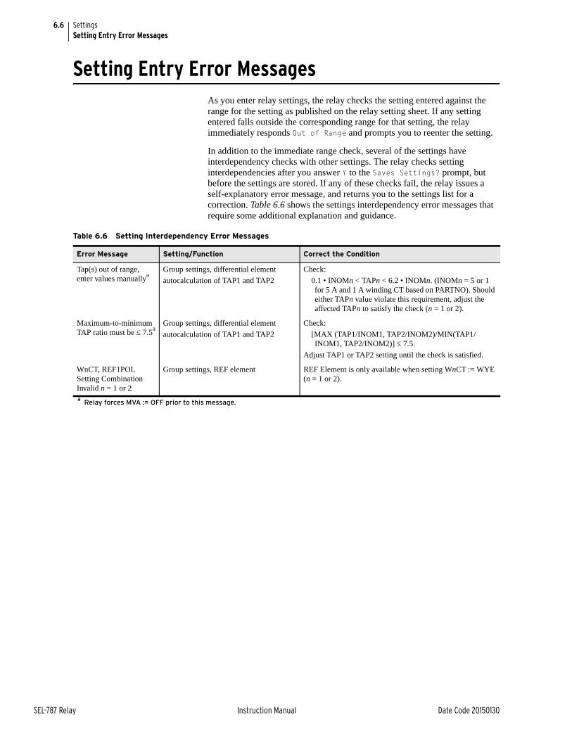
6.6
SEL-787 Relay Instruction Manual Date Code 20150130
SettingsSetting Entry Error Messages
Setting Entry Error MessagesAs you enter relay settings, the relay checks the setting entered against the range for the setting as published on the relay setting sheet. If any setting entered falls outside the corresponding range for that setting, the relay immediately responds Out of Range and prompts you to reenter the setting.
In addition to the immediate range check, several of the settings have interdependency checks with other settings. The relay checks setting interdependencies after you answer Y to the Saves Settings? prompt, but before the settings are stored. If any of these checks fail, the relay issues a self-explanatory error message, and returns you to the settings list for a correction. Table 6.6 shows the settings interdependency error messages that require some additional explanation and guidance.
Table 6.6 Setting Interdependency Error Messages
Error Message Setting/Function Correct the Condition
Tap(s) out of range, enter values manuallya
Group settings, differential element
autocalculation of TAP1 and TAP2
Check:
0.1 • INOMn < TAPn < 6.2 • INOMn. (INOMn = 5 or 1 for 5 A and 1 A winding CT based on PARTNO). Should either TAPn value violate this requirement, adjust the affected TAPn to satisfy the check (n = 1 or 2).
Maximum-to-minimum TAP ratio must be 7.5a
Group settings, differential element
autocalculation of TAP1 and TAP2
Check:
[MAX (TAP1/INOM1, TAP2/INOM2)/MIN(TAP1/INOM1, TAP2/INOM2)] 7.5.
Adjust TAP1 or TAP2 setting until the check is satisfied.
WnCT, REF1POL Setting Combination Invalid n = 1 or 2
Group settings, REF element REF Element is only available when setting WnCT := WYE (n = 1 or 2).
a Relay forces MVA := OFF prior to this message.
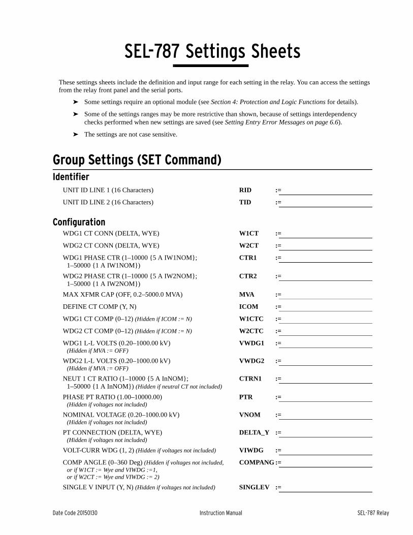
Date Code 20150130 Instruction Manual SEL-787 Relay
SEL-787 Settings SheetsInstruction Manual
These settings sheets include the definition and input range for each setting in the relay. You can access the settings from the relay front panel and the serial ports.
➤ Some settings require an optional module (see Section 4: Protection and Logic Functions for details).
➤ Some of the settings ranges may be more restrictive than shown, because of settings interdependency checks performed when new settings are saved (see Setting Entry Error Messages on page 6.6).
➤ The settings are not case sensitive.
Group Settings (SET Command)Identifier
UNIT ID LINE 1 (16 Characters) RID :=
UNIT ID LINE 2 (16 Characters) TID :=
ConfigurationWDG1 CT CONN (DELTA, WYE) W1CT :=
WDG2 CT CONN (DELTA, WYE) W2CT :=
WDG1 PHASE CTR (1–10000 {5 A IW1NOM}; 1–50000 {1 A IW1NOM})
CTR1 :=
WDG2 PHASE CTR (1–10000 {5 A IW2NOM}; 1–50000 {1 A IW2NOM})
CTR2 :=
MAX XFMR CAP (OFF, 0.2–5000.0 MVA) MVA :=
DEFINE CT COMP (Y, N) ICOM :=
WDG1 CT COMP (0–12) (Hidden if ICOM := N) W1CTC :=
WDG2 CT COMP (0–12) (Hidden if ICOM := N) W2CTC :=
WDG1 L-L VOLTS (0.20–1000.00 kV) (Hidden if MVA := OFF)
VWDG1 :=
WDG2 L-L VOLTS (0.20–1000.00 kV) (Hidden if MVA := OFF)
VWDG2 :=
NEUT 1 CT RATIO (1–10000 {5 A InNOM}; 1–50000 {1 A InNOM}) (Hidden if neutral CT not included)
CTRN1 :=
PHASE PT RATIO (1.00–10000.00) (Hidden if voltages not included)
PTR :=
NOMINAL VOLTAGE (0.20–1000.00 kV) (Hidden if voltages not included)
VNOM :=
PT CONNECTION (DELTA, WYE) (Hidden if voltages not included)
DELTA_Y :=
VOLT-CURR WDG (1, 2) (Hidden if voltages not included) VIWDG :=
COMP ANGLE (0–360 Deg) (Hidden if voltages not included,or if W1CT := Wye and VIWDG :=1, or if W2CT := Wye and VIWDG := 2)
COMPANG :=
SINGLE V INPUT (Y, N) (Hidden if voltages not included) SINGLEV :=
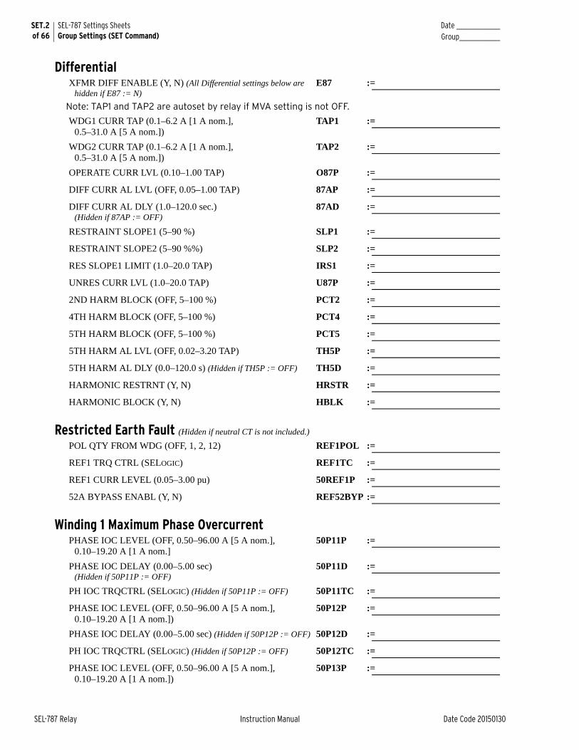
SET.2 of 66
SEL-787 Settings SheetsGroup Settings (SET Command)
Date _______________Group______________
SEL-787 Relay Instruction Manual Date Code 20150130
DifferentialXFMR DIFF ENABLE (Y, N) (All Differential settings below are
hidden if E87 := N)E87 :=
Note: TAP1 and TAP2 are autoset by relay if MVA setting is not OFF.
WDG1 CURR TAP (0.1–6.2 A [1 A nom.], 0.5–31.0 A [5 A nom.])
TAP1 :=
WDG2 CURR TAP (0.1–6.2 A [1 A nom.], 0.5–31.0 A [5 A nom.])
TAP2 :=
OPERATE CURR LVL (0.10–1.00 TAP) O87P :=
DIFF CURR AL LVL (OFF, 0.05–1.00 TAP) 87AP :=
DIFF CURR AL DLY (1.0–120.0 sec.) (Hidden if 87AP := OFF)
87AD :=
RESTRAINT SLOPE1 (5–90 %) SLP1 :=
RESTRAINT SLOPE2 (5–90 %%) SLP2 :=
RES SLOPE1 LIMIT (1.0–20.0 TAP) IRS1 :=
UNRES CURR LVL (1.0–20.0 TAP) U87P :=
2ND HARM BLOCK (OFF, 5–100 %) PCT2 :=
4TH HARM BLOCK (OFF, 5–100 %) PCT4 :=
5TH HARM BLOCK (OFF, 5–100 %) PCT5 :=
5TH HARM AL LVL (OFF, 0.02–3.20 TAP) TH5P :=
5TH HARM AL DLY (0.0–120.0 s) (Hidden if TH5P := OFF) TH5D :=
HARMONIC RESTRNT (Y, N) HRSTR :=
HARMONIC BLOCK (Y, N) HBLK :=
Restricted Earth Fault (Hidden if neutral CT is not included.)
POL QTY FROM WDG (OFF, 1, 2, 12) REF1POL :=
REF1 TRQ CTRL (SELOGIC) REF1TC :=
REF1 CURR LEVEL (0.05–3.00 pu) 50REF1P :=
52A BYPASS ENABL (Y, N) REF52BYP :=
Winding 1 Maximum Phase OvercurrentPHASE IOC LEVEL (OFF, 0.50–96.00 A [5 A nom.],
0.10–19.20 A [1 A nom.]50P11P :=
PHASE IOC DELAY (0.00–5.00 sec) (Hidden if 50P11P := OFF)
50P11D :=
PH IOC TRQCTRL (SELOGIC) (Hidden if 50P11P := OFF) 50P11TC :=
PHASE IOC LEVEL (OFF, 0.50–96.00 A [5 A nom.], 0.10–19.20 A [1 A nom.])
50P12P :=
PHASE IOC DELAY (0.00–5.00 sec) (Hidden if 50P12P := OFF) 50P12D :=
PH IOC TRQCTRL (SELOGIC) (Hidden if 50P12P := OFF) 50P12TC :=
PHASE IOC LEVEL (OFF, 0.50–96.00 A [5 A nom.], 0.10–19.20 A [1 A nom.])
50P13P :=
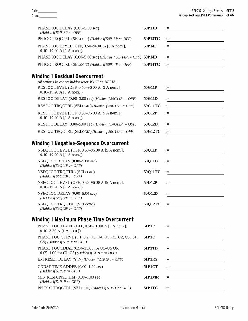
Date _______________ Group______________
SET.3of 66
SEL-787 Settings SheetsGroup Settings (SET Command)
Date Code 20150130 Instruction Manual SEL-787 Relay
PHASE IOC DELAY (0.00–5.00 sec) (Hidden if 50P13P := OFF)
50P13D :=
PH IOC TRQCTRL (SELOGIC) (Hidden if 50P13P := OFF) 50P13TC :=
PHASE IOC LEVEL (OFF, 0.50–96.00 A [5 A nom.], 0.10–19.20 A [1 A nom.])
50P14P :=
PHASE IOC DELAY (0.00–5.00 sec) (Hidden if 50P14P := OFF) 50P14D :=
PH IOC TRQCTRL (SELOGIC) (Hidden if 50P14P := OFF) 50P14TC :=
Winding 1 Residual Overcurrent(All settings below are hidden when W1CT := DELTA.)
RES IOC LEVEL (OFF, 0.50–96.00 A [5 A nom.],0.10–19.20 A [1 A nom.])
50G11P :=
RES IOC DELAY (0.00–5.00 sec) (Hidden if 50G11P := OFF) 50G11D :=
RES IOC TRQCTRL (SELOGIC) (Hidden if 50G11P := OFF) 50G11TC :=
RES IOC LEVEL (OFF, 0.50–96.00 A [5 A nom.], 0.10–19.20 A [1 A nom.])
50G12P :=
RES IOC DELAY (0.00–5.00 sec) (Hidden if 50G12P := OFF) 50G12D :=
RES IOC TRQCTRL (SELOGIC) (Hidden if 50G12P := OFF) 50G12TC :=
Winding 1 Negative-Sequence OvercurrentNSEQ IOC LEVEL (OFF, 0.50–96.00 A [5 A nom.],
0.10–19.20 A [1 A nom.])50Q11P :=
NSEQ IOC DELAY (0.00–5.00 sec)(Hidden if 50Q11P := OFF)
50Q11D :=
NSEQ IOC TRQCTRL (SELOGIC) (Hidden if 50Q11P := OFF)
50Q11TC :=
NSEQ IOC LEVEL (OFF, 0.50–96.00 A [5 A nom.], 0.10–19.20 A [1 A nom.])
50Q12P :=
NSEQ IOC DELAY (0.00–5.00 sec) (Hidden if 50Q12P := OFF)
50Q12D :=
NSEQ IOC TRQCTRL (SELOGIC) (Hidden if 50Q12P := OFF)
50Q12TC :=
Winding 1 Maximum Phase Time OvercurrentPHASE TOC LEVEL (OFF, 0.50–16.00 A [5 A nom.],
0.10–3.20 A [1 A nom.])51P1P :=
PHASE TOC CURVE (U1, U2, U3, U4, U5, C1, C2, C3, C4, C5) (Hidden if 51P1P := OFF)
51P1C :=
PHASE TOC TDIAL (0.50–15.00 for U1–U5 OR 0.05–1.00 for C1–C5) (Hidden if 51P1P := OFF)
51P1TD :=
EM RESET DELAY (Y, N) (Hidden if 51P1P := OFF) 51P1RS :=
CONST TIME ADDER (0.00–1.00 sec) (Hidden if 51P1P := OFF)
51P1CT :=
MIN RESPONSE TIM (0.00–1.00 sec) (Hidden if 51P1P := OFF)
51P1MR :=
PH TOC TRQCTRL (SELOGIC) (Hidden if 51P1P := OFF) 51P1TC :=

SET.4 of 66
SEL-787 Settings SheetsGroup Settings (SET Command)
Date _______________Group______________
SEL-787 Relay Instruction Manual Date Code 20150130
Winding 1 Phase A Time OvercurrentPHASE TOC LEVEL (OFF, 0.50–16.00 A [5 A nom.],
0.10–3.20 A [1 A nom.])51P1AP :=
PHASE TOC CURVE (U1, U2, U3, U4, U5, C1, C2, C3, C4, C5) (Hidden if 51P1AP := OFF)
51P1AC :=
PHASE TOC TDIAL (0.50–15.00 for U1–U5 OR 0.05–1.00 for C1–C5) (Hidden if 51P1AP := OFF)
51P1ATD :=
EM RESET DELAY (Y, N) (Hidden if 51P1AP := OFF) 51P1ARS :=
CONST TIME ADDER (0.00–1.00 sec) (Hidden if 51P1AP := OFF)
51P1ACT :=
MIN RESPONSE TIM (0.00–1.00 sec) (Hidden if 51P1AP := OFF)
51P1AMR :=
PH TOC TRQCTRL (SELOGIC) (Hidden if 51P1AP := OFF) 51P1ATC :=
Winding 1 Phase B Time OvercurrentPHASE TOC LEVEL (OFF, 0.50–16.00 A [5 A nom.],
0.10–3.20 A [1 A nom.])51P1BP :=
PHASE TOC CURVE (U1, U2, U3, U4, U5, C1, C2, C3, C4, C5) (Hidden if 51P1BP := OFF)
51P1BC :=
PHASE TOC TDIAL (0.50–15.00 for U1–U5 OR 0.05–1.00 for C1–C5) (Hidden if 51P1BP := OFF)
51P1BTD :=
EM RESET DELAY (Y, N) (Hidden if 51P1BP := OFF) 51P1BRS :=
CONST TIME ADDER (0.00–1.00 sec) (Hidden if 51P1BP := OFF)
51P1BCT :=
MIN RESPONSE TIM (0.00–1.00 sec) (Hidden if 51P1BP := OFF)
51P1BMR :=
PH TOC TRQCTRL (SELOGIC) (Hidden if 51P1BP := OFF) 51P1BTC :=
Winding 1 Phase C Time OvercurrentPHASE TOC LEVEL (OFF, 0.50–16.00 A [5 A nom.],
0.10–3.20 A [1 A nom.])51P1CP :=
PHASE TOC CURVE (U1, U2, U3, U4, U5, C1, C2, C3, C4, C5) (Hidden if 51P1CP := OFF)
51P1CC :=
PHASE TOC TDIAL (0.50–15.00 for U1–U5 OR 0.05–1.00 for C1–C5) (Hidden if 51P1CP := OFF)
51P1CTD :=
EM RESET DELAY (Y, N) (Hidden if 51P1CP := OFF) 51P1CRS :=
CONST TIME ADDER (0.00–1.00 sec) (Hidden if 51P1CP := OFF)
51P1CCT :=
MIN RESPONSE TIM (0.00–1.00 sec) (Hidden if 51P1CP := OFF)
51P1CMR :=
PH TOC TRQCTRL (SELOGIC) (Hidden if 51P1CP := OFF) 51P1CTC :=
Winding 1 Residual Time OvercurrentAll settings below are hidden when W1CT := DELTA.
RES TOC LEVEL (OFF, 0.50–16.00 A [5 A nom.],0.10–3.20 A [1 A nom.])
51G1P :=
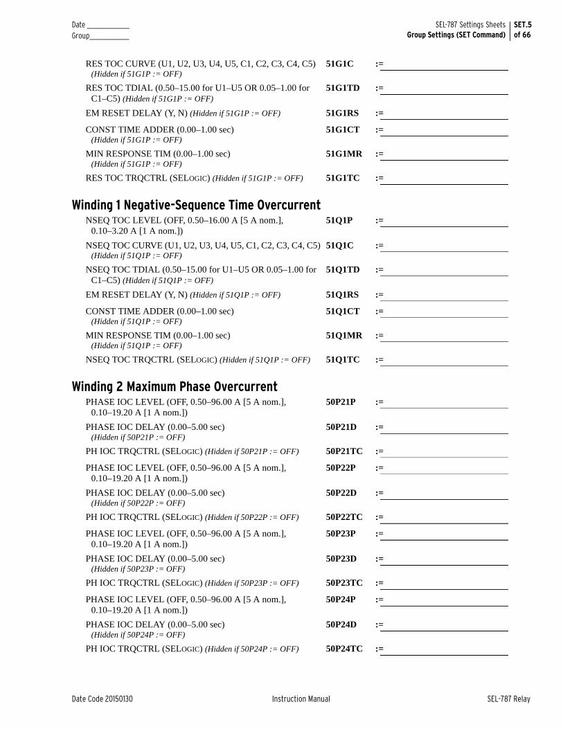
Date _______________ Group______________
SET.5of 66
SEL-787 Settings SheetsGroup Settings (SET Command)
Date Code 20150130 Instruction Manual SEL-787 Relay
RES TOC CURVE (U1, U2, U3, U4, U5, C1, C2, C3, C4, C5)(Hidden if 51G1P := OFF)
51G1C :=
RES TOC TDIAL (0.50–15.00 for U1–U5 OR 0.05–1.00 for C1–C5) (Hidden if 51G1P := OFF)
51G1TD :=
EM RESET DELAY (Y, N) (Hidden if 51G1P := OFF) 51G1RS :=
CONST TIME ADDER (0.00–1.00 sec) (Hidden if 51G1P := OFF)
51G1CT :=
MIN RESPONSE TIM (0.00–1.00 sec) (Hidden if 51G1P := OFF)
51G1MR :=
RES TOC TRQCTRL (SELOGIC) (Hidden if 51G1P := OFF) 51G1TC :=
Winding 1 Negative-Sequence Time OvercurrentNSEQ TOC LEVEL (OFF, 0.50–16.00 A [5 A nom.],
0.10–3.20 A [1 A nom.])51Q1P :=
NSEQ TOC CURVE (U1, U2, U3, U4, U5, C1, C2, C3, C4, C5)(Hidden if 51Q1P := OFF)
51Q1C :=
NSEQ TOC TDIAL (0.50–15.00 for U1–U5 OR 0.05–1.00 for C1–C5) (Hidden if 51Q1P := OFF)
51Q1TD :=
EM RESET DELAY (Y, N) (Hidden if 51Q1P := OFF) 51Q1RS :=
CONST TIME ADDER (0.00–1.00 sec) (Hidden if 51Q1P := OFF)
51Q1CT :=
MIN RESPONSE TIM (0.00–1.00 sec) (Hidden if 51Q1P := OFF)
51Q1MR :=
NSEQ TOC TRQCTRL (SELOGIC) (Hidden if 51Q1P := OFF) 51Q1TC :=
Winding 2 Maximum Phase OvercurrentPHASE IOC LEVEL (OFF, 0.50–96.00 A [5 A nom.],
0.10–19.20 A [1 A nom.])50P21P :=
PHASE IOC DELAY (0.00–5.00 sec)(Hidden if 50P21P := OFF)
50P21D :=
PH IOC TRQCTRL (SELOGIC) (Hidden if 50P21P := OFF) 50P21TC :=
PHASE IOC LEVEL (OFF, 0.50–96.00 A [5 A nom.], 0.10–19.20 A [1 A nom.])
50P22P :=
PHASE IOC DELAY (0.00–5.00 sec) (Hidden if 50P22P := OFF)
50P22D :=
PH IOC TRQCTRL (SELOGIC) (Hidden if 50P22P := OFF) 50P22TC :=
PHASE IOC LEVEL (OFF, 0.50–96.00 A [5 A nom.], 0.10–19.20 A [1 A nom.])
50P23P :=
PHASE IOC DELAY (0.00–5.00 sec) (Hidden if 50P23P := OFF)
50P23D :=
PH IOC TRQCTRL (SELOGIC) (Hidden if 50P23P := OFF) 50P23TC :=
PHASE IOC LEVEL (OFF, 0.50–96.00 A [5 A nom.], 0.10–19.20 A [1 A nom.])
50P24P :=
PHASE IOC DELAY (0.00–5.00 sec) (Hidden if 50P24P := OFF)
50P24D :=
PH IOC TRQCTRL (SELOGIC) (Hidden if 50P24P := OFF) 50P24TC :=
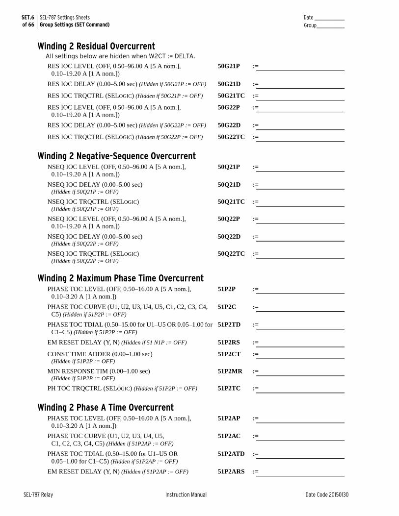
SET.6 of 66
SEL-787 Settings SheetsGroup Settings (SET Command)
Date _______________Group______________
SEL-787 Relay Instruction Manual Date Code 20150130
Winding 2 Residual OvercurrentAll settings below are hidden when W2CT := DELTA.
RES IOC LEVEL (OFF, 0.50–96.00 A [5 A nom.],0.10–19.20 A [1 A nom.])
50G21P :=
RES IOC DELAY (0.00–5.00 sec) (Hidden if 50G21P := OFF) 50G21D :=
RES IOC TRQCTRL (SELOGIC) (Hidden if 50G21P := OFF) 50G21TC :=
RES IOC LEVEL (OFF, 0.50–96.00 A [5 A nom.],0.10–19.20 A [1 A nom.])
50G22P :=
RES IOC DELAY (0.00–5.00 sec) (Hidden if 50G22P := OFF) 50G22D :=
RES IOC TRQCTRL (SELOGIC) (Hidden if 50G22P := OFF) 50G22TC :=
Winding 2 Negative-Sequence OvercurrentNSEQ IOC LEVEL (OFF, 0.50–96.00 A [5 A nom.],
0.10–19.20 A [1 A nom.])50Q21P :=
NSEQ IOC DELAY (0.00–5.00 sec)(Hidden if 50Q21P := OFF)
50Q21D :=
NSEQ IOC TRQCTRL (SELOGIC) (Hidden if 50Q21P := OFF)
50Q21TC :=
NSEQ IOC LEVEL (OFF, 0.50–96.00 A [5 A nom.], 0.10–19.20 A [1 A nom.])
50Q22P :=
NSEQ IOC DELAY (0.00–5.00 sec) (Hidden if 50Q22P := OFF)
50Q22D :=
NSEQ IOC TRQCTRL (SELOGIC) (Hidden if 50Q22P := OFF)
50Q22TC :=
Winding 2 Maximum Phase Time OvercurrentPHASE TOC LEVEL (OFF, 0.50–16.00 A [5 A nom.],
0.10–3.20 A [1 A nom.])51P2P :=
PHASE TOC CURVE (U1, U2, U3, U4, U5, C1, C2, C3, C4, C5) (Hidden if 51P2P := OFF)
51P2C :=
PHASE TOC TDIAL (0.50–15.00 for U1–U5 OR 0.05–1.00 for C1–C5) (Hidden if 51P2P := OFF)
51P2TD :=
EM RESET DELAY (Y, N) (Hidden if 51 N1P := OFF) 51P2RS :=
CONST TIME ADDER (0.00–1.00 sec) (Hidden if 51P2P := OFF)
51P2CT :=
MIN RESPONSE TIM (0.00–1.00 sec) (Hidden if 51P2P := OFF)
51P2MR :=
PH TOC TRQCTRL (SELOGIC) (Hidden if 51P2P := OFF) 51P2TC :=
Winding 2 Phase A Time OvercurrentPHASE TOC LEVEL (OFF, 0.50–16.00 A [5 A nom.],
0.10–3.20 A [1 A nom.])51P2AP :=
PHASE TOC CURVE (U1, U2, U3, U4, U5, C1, C2, C3, C4, C5) (Hidden if 51P2AP := OFF)
51P2AC :=
PHASE TOC TDIAL (0.50–15.00 for U1–U5 OR 0.05–1.00 for C1–C5) (Hidden if 51P2AP := OFF)
51P2ATD :=
EM RESET DELAY (Y, N) (Hidden if 51P2AP := OFF) 51P2ARS :=
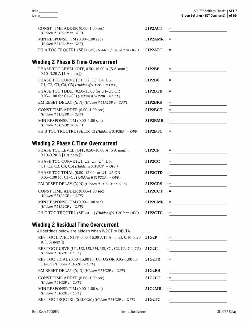
Date _______________ Group______________
SET.7of 66
SEL-787 Settings SheetsGroup Settings (SET Command)
Date Code 20150130 Instruction Manual SEL-787 Relay
CONST TIME ADDER (0.00–1.00 sec) (Hidden if 51P2AP := OFF)
51P2ACT :=
MIN RESPONSE TIM (0.00–1.00 sec) (Hidden if 51P2AP := OFF)
51P2AMR :=
PH A TOC TRQCTRL (SELOGIC) (Hidden if 51P2AP := OFF) 51P2ATC :=
Winding 2 Phase B Time OvercurrentPHASE TOC LEVEL (OFF, 0.50–16.00 A [5 A nom.],
0.10–3.20 A [1 A nom.])51P2BP :=
PHASE TOC CURVE (U1, U2, U3, U4, U5, C1, C2, C3, C4, C5) (Hidden if 51P2BP := OFF)
51P2BC :=
PHASE TOC TDIAL (0.50–15.00 for U1–U5 OR 0.05–1.00 for C1–C5) (Hidden if 51P2BP := OFF)
51P2BTD :=
EM RESET DELAY (Y, N) (Hidden if 51P2BP := OFF) 51P2BRS :=
CONST TIME ADDER (0.00–1.00 sec) (Hidden if 51P2BP := OFF)
51P2BCT :=
MIN RESPONSE TIM (0.00–1.00 sec) (Hidden if 51P2BP := OFF)
51P2BMR :=
PH B TOC TRQCTRL (SELOGIC) (Hidden if 51P2BP := OFF) 51P2BTC :=
Winding 2 Phase C Time OvercurrentPHASE TOC LEVEL (OFF, 0.50–16.00 A [5 A nom.],
0.10–3.20 A [1 A nom.])51P2CP :=
PHASE TOC CURVE (U1, U2, U3, U4, U5, C1, C2, C3, C4, C5) (Hidden if 51P2CP := OFF)
51P2CC :=
PHASE TOC TDIAL (0.50–15.00 for U1–U5 OR 0.05–1.00 for C1–C5) (Hidden if 51P2CP := OFF)
51P2CTD :=
EM RESET DELAY (Y, N) (Hidden if 51P2CP := OFF) 51P2CRS :=
CONST TIME ADDER (0.00–1.00 sec) (Hidden if 51P2CP := OFF)
51P2CCT :=
MIN RESPONSE TIM (0.00–1.00 sec) (Hidden if 51P2CP := OFF)
51P2CMR :=
PH C TOC TRQCTRL (SELOGIC) (Hidden if 51P2CP := OFF) 51P2CTC :=
Winding 2 Residual Time OvercurrentAll settings below are hidden when W2CT := DELTA.
RES TOC LEVEL (OFF, 0.50–16.00 A [5 A nom.], 0.10–3.20 A [1 A nom.])
51G2P :=
RES TOC CURVE (U1, U2, U3, U4, U5, C1, C2, C3, C4, C5) (Hidden if 51G2P := OFF)
51G2C :=
RES TOC TDIAL (0.50–15.00 for U1–U5 OR 0.05–1.00 for C1–C5) (Hidden if 51G2P := OFF)
51G2TD :=
EM RESET DELAY (Y, N) (Hidden if 51G2P := OFF) 51G2RS :=
CONST TIME ADDER (0.00–1.00 sec) (Hidden if 51G2P := OFF)
51G2CT :=
MIN RESPONSE TIM (0.00–1.00 sec) (Hidden if 51G2P := OFF)
51G2MR :=
RES TOC TRQCTRL (SELOGIC) (Hidden if 51G2P := OFF) 51G2TC :=
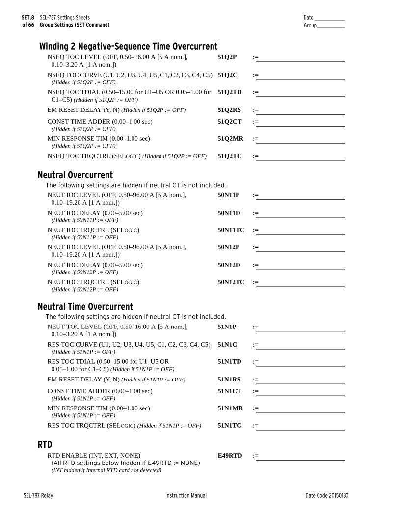
SET.8 of 66
SEL-787 Settings SheetsGroup Settings (SET Command)
Date _______________Group______________
SEL-787 Relay Instruction Manual Date Code 20150130
Winding 2 Negative-Sequence Time OvercurrentNSEQ TOC LEVEL (OFF, 0.50–16.00 A [5 A nom.],
0.10–3.20 A [1 A nom.])51Q2P :=
NSEQ TOC CURVE (U1, U2, U3, U4, U5, C1, C2, C3, C4, C5) (Hidden if 51Q2P := OFF)
51Q2C :=
NSEQ TOC TDIAL (0.50–15.00 for U1–U5 OR 0.05–1.00 for C1–C5) (Hidden if 51Q2P := OFF)
51Q2TD :=
EM RESET DELAY (Y, N) (Hidden if 51Q2P := OFF) 51Q2RS :=
CONST TIME ADDER (0.00–1.00 sec)(Hidden if 51Q2P := OFF)
51Q2CT :=
MIN RESPONSE TIM (0.00–1.00 sec) (Hidden if 51Q2P := OFF)
51Q2MR :=
NSEQ TOC TRQCTRL (SELOGIC) (Hidden if 51Q2P := OFF) 51Q2TC :=
Neutral OvercurrentThe following settings are hidden if neutral CT is not included.
NEUT IOC LEVEL (OFF, 0.50–96.00 A [5 A nom.], 0.10–19.20 A [1 A nom.])
50N11P :=
NEUT IOC DELAY (0.00–5.00 sec)(Hidden if 50N11P := OFF)
50N11D :=
NEUT IOC TRQCTRL (SELOGIC)(Hidden if 50N11P := OFF)
50N11TC :=
NEUT IOC LEVEL (OFF, 0.50–96.00 A [5 A nom.], 0.10–19.20 A [1 A nom.])
50N12P :=
NEUT IOC DELAY (0.00–5.00 sec) (Hidden if 50N12P := OFF)
50N12D :=
NEUT IOC TRQCTRL (SELOGIC) (Hidden if 50N12P := OFF)
50N12TC :=
Neutral Time OvercurrentThe following settings are hidden if neutral CT is not included.
NEUT TOC LEVEL (OFF, 0.50–16.00 A [5 A nom.], 0.10–3.20 A [1 A nom.])
51N1P :=
RES TOC CURVE (U1, U2, U3, U4, U5, C1, C2, C3, C4, C5)(Hidden if 51N1P := OFF)
51N1C :=
RES TOC TDIAL (0.50–15.00 for U1–U5 OR 0.05–1.00 for C1–C5) (Hidden if 51N1P := OFF)
51N1TD :=
EM RESET DELAY (Y, N) (Hidden if 51N1P := OFF) 51N1RS :=
CONST TIME ADDER (0.00–1.00 sec) (Hidden if 51N1P := OFF)
51N1CT :=
MIN RESPONSE TIM (0.00–1.00 sec) (Hidden if 51N1P := OFF)
51N1MR :=
RES TOC TRQCTRL (SELOGIC) (Hidden if 51N1P := OFF) 51N1TC :=
RTD RTD ENABLE (INT, EXT, NONE)
(All RTD settings below hidden if E49RTD := NONE)(INT hidden if Internal RTD card not detected)
E49RTD :=

Date _______________ Group______________
SET.9of 66
SEL-787 Settings SheetsGroup Settings (SET Command)
Date Code 20150130 Instruction Manual SEL-787 Relay
RTD1 LOCATION (OFF, AMB, OTH) RTD1LOC :=
RTD1 IDENTIFIER (10 characters)(Hidden if RTD1LOC := OFF or AMB)
RTD1NAM :=
RTD1 TYPE (PT100, NI100, NI120, CU10)(All RTD settings below hidden if E49RTD := NONE)
RTD1TY :=
RTD1 TRIP LEVEL (OFF, 1–250 degC) (Hidden if RTD1LOC := OFF)
TRTMP1 :=
RTD1 WARN LEVEL (OFF, 1–250 degC)(Hidden if RTD1LOC := OFF)
ALTMP1 :=
RTD2 LOCATION (OFF, AMB, OTH) RTD2LOC :=
RTD2 IDENTIFIER (10 characters)(Hidden if RTD2LOC := OFF or AMB)
RTD2NAM :=
RTD2 TYPE (PT100, NI100, NI120, CU10) (Hidden if RTD2LOC := OFF)
RTD2TY :=
RTD2 TRIP LEVEL (OFF, 1–250 degC) (Hidden if RTD2LOC := OFF)
TRTMP2 :=
RTD2 WARN LEVEL (OFF, 1–250 degC) (Hidden if RTD2LOC := OFF)
ALTMP2 :=
RTD3 LOCATION (OFF, AMB, OTH) RTD3LOC :=
RTD3 IDENTIFIER (10 characters) (Hidden if RTD3LOC := OFF or AMB)
RTD3NAM :=
RTD3 TYPE (PT100, NI100, NI120, CU10)(Hidden if RTD3LOC := OFF)
RTD3TY :=
RTD3 TRIP LEVEL (OFF, 1–250 degC)(Hidden if RTD3LOC := OFF)
TRTMP3 :=
RTD3 WARN LEVEL (OFF, 1–250 degC)(Hidden if RTD3LOC := OFF)
ALTMP3 :=
RTD4 LOCATION (OFF, AMB, OTH) RTD4LOC :=
RTD4 IDENTIFIER (10 characters)(Hidden if RTD4LOC := OFF or AMB)
RTD4NAM :=
RTD4 TYPE (PT100, NI100, NI120, CU10) (Hidden if RTD4LOC := OFF)
RTD4TY :=
RTD4 TRIP LEVEL (OFF, 1–250 degC)(Hidden if RTD4LOC := OFF)
TRTMP4 :=
RTD4 WARN LEVEL (OFF, 1–250 degC)(Hidden if RTD4LOC := OFF)
ALTMP4 :=
RTD5 LOCATION (OFF, AMB, OTH) RTD5LOC :=
RTD5 IDENTIFIER (10 characters)(Hidden if RTD5LOC := OFF or AMB)
RTD5NAM :=
RTD5 TYPE (PT100, NI100, NI120, CU10)(Hidden if RTD5LOC := OFF)
RTD5TY :=
RTD5 TRIP LEVEL (OFF, 1–250 degC)(Hidden if RTD5LOC := OFF)
TRTMP5 :=
RTD5 WARN LEVEL (OFF, 1–250 degC)(Hidden if RTD5LOC := OFF)
ALTMP5 :=

SET.10 of 66
SEL-787 Settings SheetsGroup Settings (SET Command)
Date _______________Group______________
SEL-787 Relay Instruction Manual Date Code 20150130
RTD6 LOCATION (OFF, AMB, OTH) RTD6LOC :=
RTD6 IDENTIFIER (10 characters) (Hidden if RTD6LOC := OFF or AMB)
RTD6NAM :=
RTD6 TYPE (PT100, NI100, NI120, CU10)(Hidden if RTD6LOC := OFF)
RTD6TY :=
RTD6 TRIP LEVEL (OFF, 1–250 degC)(Hidden if RTD6LOC := OFF)
TRTMP6 :=
RTD6 WARN LEVEL (OFF, 1–250 degC)(Hidden if RTD6LOC := OFF)
ALTMP6 :=
RTD7 LOCATION (OFF, AMB, OTH) RTD7LOC :=
RTD7 IDENTIFIER (10 characters)(Hidden if RTD7LOC := OFF or AMB)
RTD7NAM :=
RTD7 TYPE (PT100, NI100, NI120, CU10)(Hidden if RTD7LOC := OFF)
RTD7TY :=
RTD7 TRIP LEVEL (OFF, 1–250 degC)(Hidden if RTD7LOC := OFF)
TRTMP7 :=
RTD7 WARN LEVEL (OFF, 1–250 degC)(Hidden if RTD7LOC := OFF)
ALTMP7 :=
RTD8 LOCATION (OFF, AMB, OTH) RTD8LOC :=
RTD8 IDENTIFIER (10 characters)(Hidden if RTD8LOC := OFF or AMB)
RTD8NAM :=
RTD8 TYPE (PT100, NI100, NI120, CU10)(Hidden if RTD8LOC := OFF)
RTD8TY :=
RTD8 TRIP LEVEL (OFF, 1–250 degC)(Hidden if RTD8LOC := OFF)
TRTMP8 :=
RTD8 WARN LEVEL (OFF, 1–250 degC)(Hidden if RTD8LOC := OFF)
ALTMP8 :=
RTD9 LOCATION (OFF, AMB, OTH) RTD9LOC :=
RTD9 IDENTIFIER (10 characters)(Hidden if RTD9LOC := OFF or AMB)
RTD9NAM :=
RTD9 TYPE (PT100, NI100, NI120, CU10)(Hidden if RTD9LOC := OFF)
RTD9TY :=
RTD9 TRIP LEVEL (OFF, 1–250 degC)(Hidden if RTD9LOC := OFF)
TRTMP9 :=
RTD9 WARN LEVEL (OFF, 1–250 degC)(Hidden if RTD9LOC := OFF)
ALTMP9 :=
RTD10 LOCATION (OFF, AMB, OTH) RTD10LOC:=
RTD10 IDENTIFIER (10 characters)(Hidden if RTD10LOC := OFF or AMB)
RTD10NAM:=
RTD10 TYPE (PT100, NI100, NI120, CU10)(Hidden if RTD10LOC := OFF)
RTD10TY :=
RTD10 TRIP LEVEL (OFF, 1–250 degC)(Hidden if RTD10LOC := OFF)
TRTMP10 :=
RTD10 WARN LEVEL (OFF, 1–250 degC)(Hidden if RTD10LOC := OFF)
ALTMP10 :=
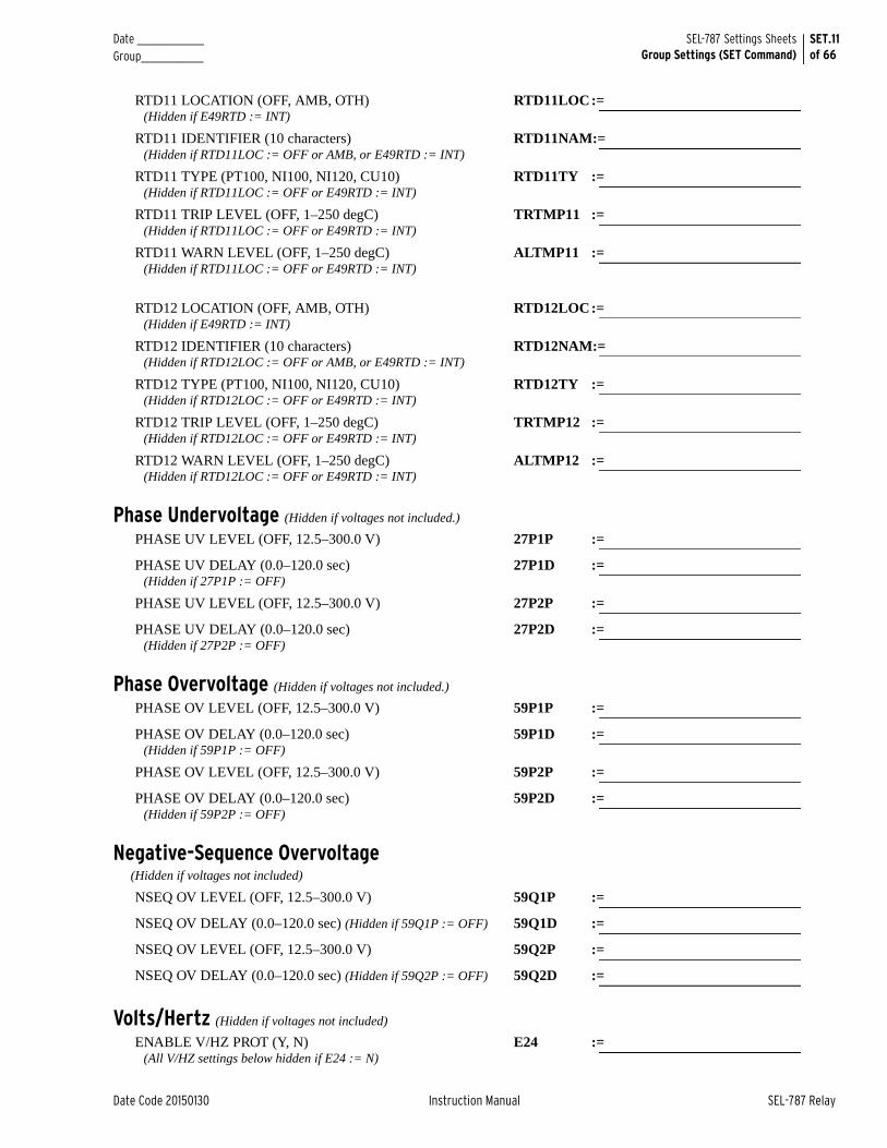
Date _______________ Group______________
SET.11of 66
SEL-787 Settings SheetsGroup Settings (SET Command)
Date Code 20150130 Instruction Manual SEL-787 Relay
RTD11 LOCATION (OFF, AMB, OTH) (Hidden if E49RTD := INT)
RTD11LOC:=
RTD11 IDENTIFIER (10 characters)(Hidden if RTD11LOC := OFF or AMB, or E49RTD := INT)
RTD11NAM:=
RTD11 TYPE (PT100, NI100, NI120, CU10)(Hidden if RTD11LOC := OFF or E49RTD := INT)
RTD11TY :=
RTD11 TRIP LEVEL (OFF, 1–250 degC)(Hidden if RTD11LOC := OFF or E49RTD := INT)
TRTMP11 :=
RTD11 WARN LEVEL (OFF, 1–250 degC) (Hidden if RTD11LOC := OFF or E49RTD := INT)
ALTMP11 :=
RTD12 LOCATION (OFF, AMB, OTH)(Hidden if E49RTD := INT)
RTD12LOC:=
RTD12 IDENTIFIER (10 characters)(Hidden if RTD12LOC := OFF or AMB, or E49RTD := INT)
RTD12NAM:=
RTD12 TYPE (PT100, NI100, NI120, CU10)(Hidden if RTD12LOC := OFF or E49RTD := INT)
RTD12TY :=
RTD12 TRIP LEVEL (OFF, 1–250 degC)(Hidden if RTD12LOC := OFF or E49RTD := INT)
TRTMP12 :=
RTD12 WARN LEVEL (OFF, 1–250 degC)(Hidden if RTD12LOC := OFF or E49RTD := INT)
ALTMP12 :=
Phase Undervoltage (Hidden if voltages not included.)
PHASE UV LEVEL (OFF, 12.5–300.0 V) 27P1P :=
PHASE UV DELAY (0.0–120.0 sec) (Hidden if 27P1P := OFF)
27P1D :=
PHASE UV LEVEL (OFF, 12.5–300.0 V) 27P2P :=
PHASE UV DELAY (0.0–120.0 sec) (Hidden if 27P2P := OFF)
27P2D :=
Phase Overvoltage (Hidden if voltages not included.)
PHASE OV LEVEL (OFF, 12.5–300.0 V) 59P1P :=
PHASE OV DELAY (0.0–120.0 sec) (Hidden if 59P1P := OFF)
59P1D :=
PHASE OV LEVEL (OFF, 12.5–300.0 V) 59P2P :=
PHASE OV DELAY (0.0–120.0 sec) (Hidden if 59P2P := OFF)
59P2D :=
Negative-Sequence Overvoltage (Hidden if voltages not included)
NSEQ OV LEVEL (OFF, 12.5–300.0 V) 59Q1P :=
NSEQ OV DELAY (0.0–120.0 sec) (Hidden if 59Q1P := OFF) 59Q1D :=
NSEQ OV LEVEL (OFF, 12.5–300.0 V) 59Q2P :=
NSEQ OV DELAY (0.0–120.0 sec) (Hidden if 59Q2P := OFF) 59Q2D :=
Volts/Hertz (Hidden if voltages not included)
ENABLE V/HZ PROT (Y, N)(All V/HZ settings below hidden if E24 := N)
E24 :=
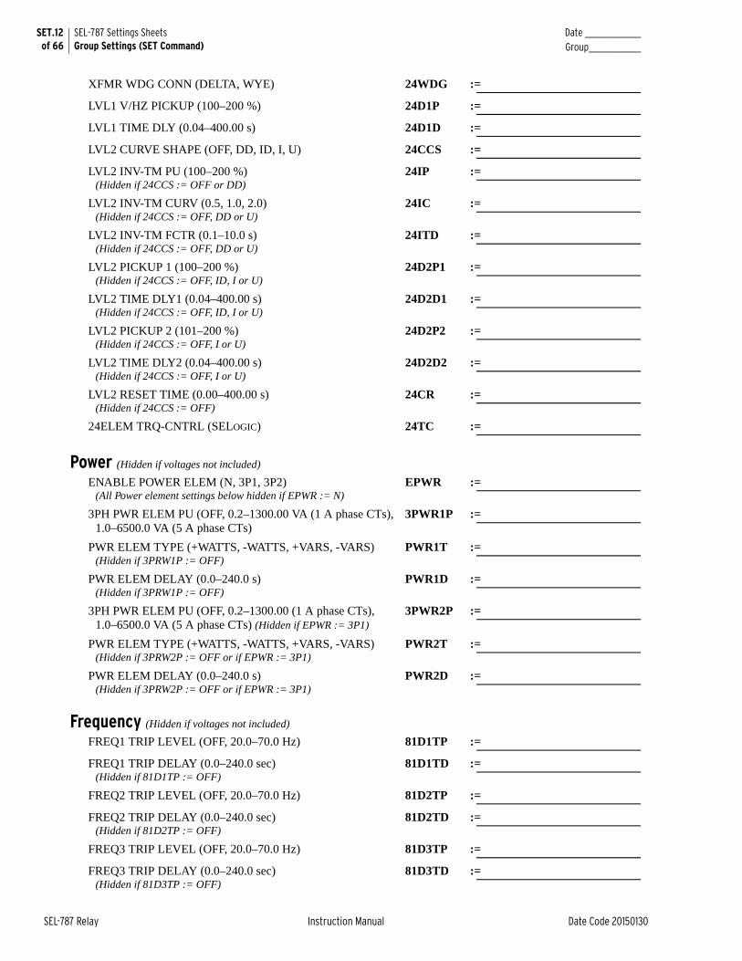
SET.12 of 66
SEL-787 Settings SheetsGroup Settings (SET Command)
Date _______________Group______________
SEL-787 Relay Instruction Manual Date Code 20150130
XFMR WDG CONN (DELTA, WYE) 24WDG :=
LVL1 V/HZ PICKUP (100–200 %) 24D1P :=
LVL1 TIME DLY (0.04–400.00 s) 24D1D :=
LVL2 CURVE SHAPE (OFF, DD, ID, I, U) 24CCS :=
LVL2 INV-TM PU (100–200 %)(Hidden if 24CCS := OFF or DD)
24IP :=
LVL2 INV-TM CURV (0.5, 1.0, 2.0) (Hidden if 24CCS := OFF, DD or U)
24IC :=
LVL2 INV-TM FCTR (0.1–10.0 s)(Hidden if 24CCS := OFF, DD or U)
24ITD :=
LVL2 PICKUP 1 (100–200 %)(Hidden if 24CCS := OFF, ID, I or U)
24D2P1 :=
LVL2 TIME DLY1 (0.04–400.00 s) (Hidden if 24CCS := OFF, ID, I or U)
24D2D1 :=
LVL2 PICKUP 2 (101–200 %) (Hidden if 24CCS := OFF, I or U)
24D2P2 :=
LVL2 TIME DLY2 (0.04–400.00 s)(Hidden if 24CCS := OFF, I or U)
24D2D2 :=
LVL2 RESET TIME (0.00–400.00 s) (Hidden if 24CCS := OFF)
24CR :=
24ELEM TRQ-CNTRL (SELOGIC) 24TC :=
Power (Hidden if voltages not included)
ENABLE POWER ELEM (N, 3P1, 3P2)(All Power element settings below hidden if EPWR := N)
EPWR :=
3PH PWR ELEM PU (OFF, 0.2–1300.00 VA (1 A phase CTs),1.0–6500.0 VA (5 A phase CTs)
3PWR1P :=
PWR ELEM TYPE (+WATTS, -WATTS, +VARS, -VARS)(Hidden if 3PRW1P := OFF)
PWR1T :=
PWR ELEM DELAY (0.0–240.0 s)(Hidden if 3PRW1P := OFF)
PWR1D :=
3PH PWR ELEM PU (OFF, 0.2–1300.00 (1 A phase CTs),1.0–6500.0 VA (5 A phase CTs) (Hidden if EPWR := 3P1)
3PWR2P :=
PWR ELEM TYPE (+WATTS, -WATTS, +VARS, -VARS)(Hidden if 3PRW2P := OFF or if EPWR := 3P1)
PWR2T :=
PWR ELEM DELAY (0.0–240.0 s)(Hidden if 3PRW2P := OFF or if EPWR := 3P1)
PWR2D :=
Frequency (Hidden if voltages not included)
FREQ1 TRIP LEVEL (OFF, 20.0–70.0 Hz) 81D1TP :=
FREQ1 TRIP DELAY (0.0–240.0 sec)(Hidden if 81D1TP := OFF)
81D1TD :=
FREQ2 TRIP LEVEL (OFF, 20.0–70.0 Hz) 81D2TP :=
FREQ2 TRIP DELAY (0.0–240.0 sec)(Hidden if 81D2TP := OFF)
81D2TD :=
FREQ3 TRIP LEVEL (OFF, 20.0–70.0 Hz) 81D3TP :=
FREQ3 TRIP DELAY (0.0–240.0 sec) (Hidden if 81D3TP := OFF)
81D3TD :=
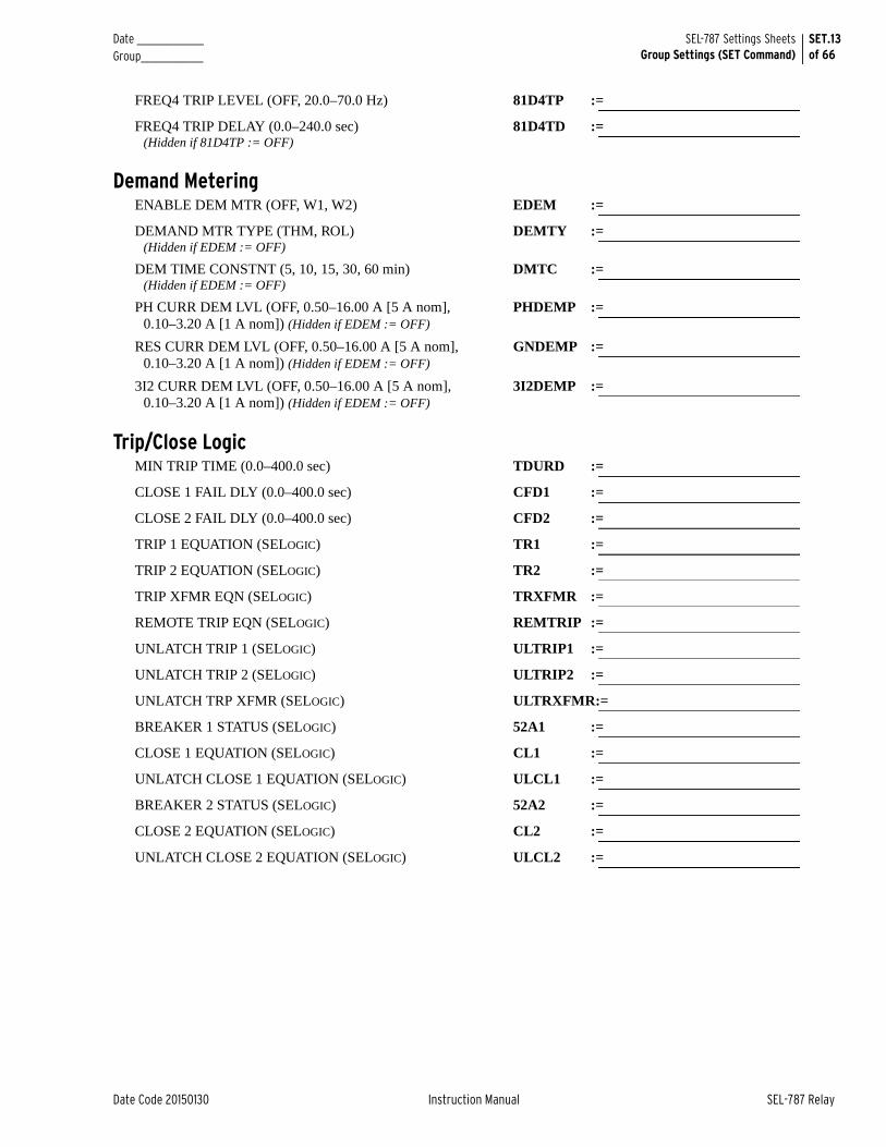
Date _______________ Group______________
SET.13of 66
SEL-787 Settings SheetsGroup Settings (SET Command)
Date Code 20150130 Instruction Manual SEL-787 Relay
FREQ4 TRIP LEVEL (OFF, 20.0–70.0 Hz) 81D4TP :=
FREQ4 TRIP DELAY (0.0–240.0 sec)(Hidden if 81D4TP := OFF)
81D4TD :=
Demand MeteringENABLE DEM MTR (OFF, W1, W2) EDEM :=
DEMAND MTR TYPE (THM, ROL) (Hidden if EDEM := OFF)
DEMTY :=
DEM TIME CONSTNT (5, 10, 15, 30, 60 min) (Hidden if EDEM := OFF)
DMTC :=
PH CURR DEM LVL (OFF, 0.50–16.00 A [5 A nom], 0.10–3.20 A [1 A nom]) (Hidden if EDEM := OFF)
PHDEMP :=
RES CURR DEM LVL (OFF, 0.50–16.00 A [5 A nom], 0.10–3.20 A [1 A nom]) (Hidden if EDEM := OFF)
GNDEMP :=
3I2 CURR DEM LVL (OFF, 0.50–16.00 A [5 A nom], 0.10–3.20 A [1 A nom]) (Hidden if EDEM := OFF)
3I2DEMP :=
Trip/Close LogicMIN TRIP TIME (0.0–400.0 sec) TDURD :=
CLOSE 1 FAIL DLY (0.0–400.0 sec) CFD1 :=
CLOSE 2 FAIL DLY (0.0–400.0 sec) CFD2 :=
TRIP 1 EQUATION (SELOGIC) TR1 :=
TRIP 2 EQUATION (SELOGIC) TR2 :=
TRIP XFMR EQN (SELOGIC) TRXFMR :=
REMOTE TRIP EQN (SELOGIC) REMTRIP :=
UNLATCH TRIP 1 (SELOGIC) ULTRIP1 :=
UNLATCH TRIP 2 (SELOGIC) ULTRIP2 :=
UNLATCH TRP XFMR (SELOGIC) ULTRXFMR:=
BREAKER 1 STATUS (SELOGIC) 52A1 :=
CLOSE 1 EQUATION (SELOGIC) CL1 :=
UNLATCH CLOSE 1 EQUATION (SELOGIC) ULCL1 :=
BREAKER 2 STATUS (SELOGIC) 52A2 :=
CLOSE 2 EQUATION (SELOGIC) CL2 :=
UNLATCH CLOSE 2 EQUATION (SELOGIC) ULCL2 :=
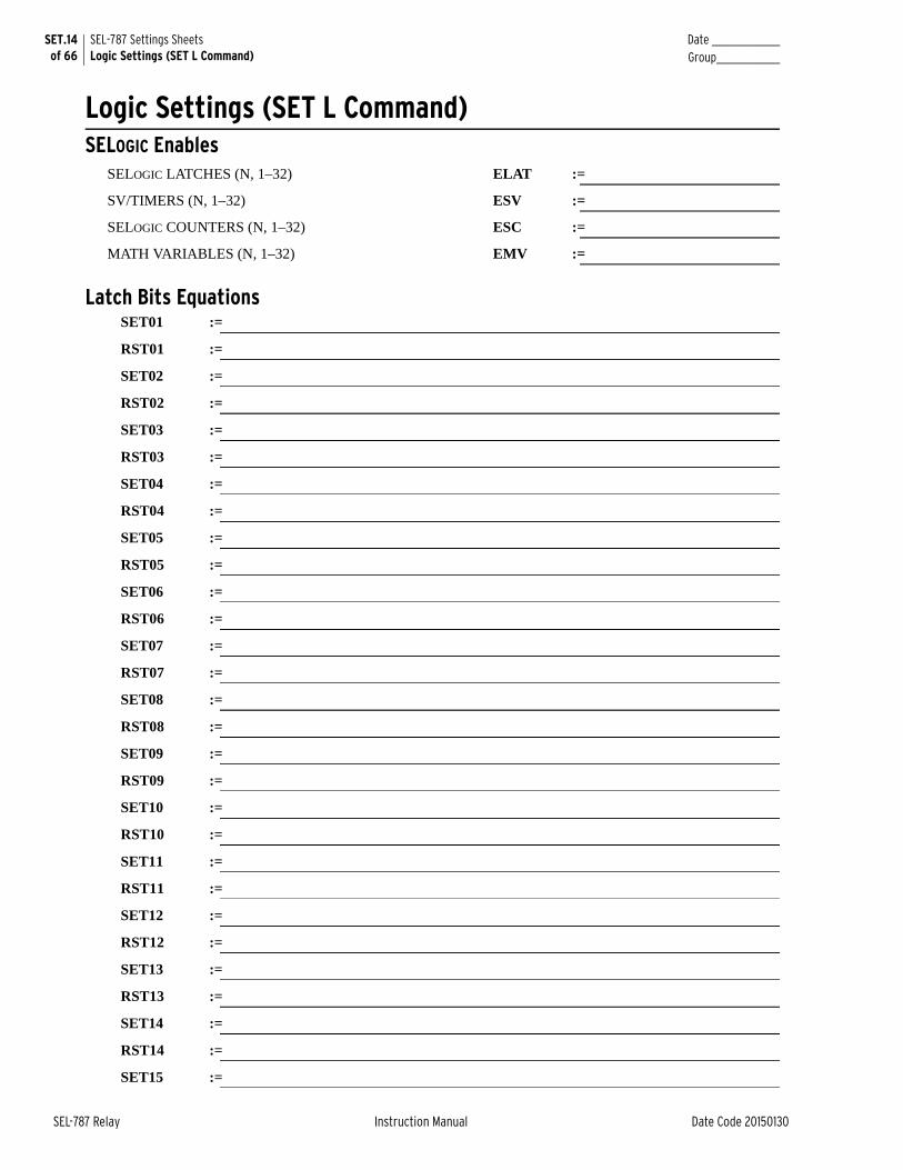
SET.14 of 66
SEL-787 Settings SheetsLogic Settings (SET L Command)
Date _______________Group______________
SEL-787 Relay Instruction Manual Date Code 20150130
Logic Settings (SET L Command)SELOGIC Enables
SELOGIC LATCHES (N, 1–32) ELAT :=
SV/TIMERS (N, 1–32) ESV :=
SELOGIC COUNTERS (N, 1–32) ESC :=
MATH VARIABLES (N, 1–32) EMV :=
Latch Bits EquationsSET01 :=
RST01 :=
SET02 :=
RST02 :=
SET03 :=
RST03 :=
SET04 :=
RST04 :=
SET05 :=
RST05 :=
SET06 :=
RST06 :=
SET07 :=
RST07 :=
SET08 :=
RST08 :=
SET09 :=
RST09 :=
SET10 :=
RST10 :=
SET11 :=
RST11 :=
SET12 :=
RST12 :=
SET13 :=
RST13 :=
SET14 :=
RST14 :=
SET15 :=
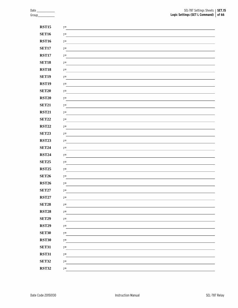
Date _______________ Group______________
SET.15of 66
SEL-787 Settings SheetsLogic Settings (SET L Command)
Date Code 20150130 Instruction Manual SEL-787 Relay
RST15 :=
SET16 :=
RST16 :=
SET17 :=
RST17 :=
SET18 :=
RST18 :=
SET19 :=
RST19 :=
SET20 :=
RST20 :=
SET21 :=
RST21 :=
SET22 :=
RST22 :=
SET23 :=
RST23 :=
SET24 :=
RST24 :=
SET25 :=
RST25 :=
SET26 :=
RST26 :=
SET27 :=
RST27 :=
SET28 :=
RST28 :=
SET29 :=
RST29 :=
SET30 :=
RST30 :=
SET31 :=
RST31 :=
SET32 :=
RST32 :=
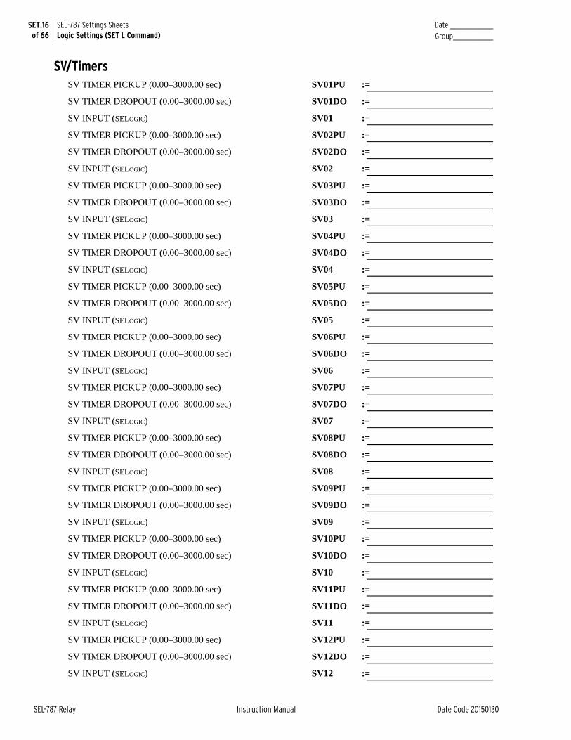
SET.16 of 66
SEL-787 Settings SheetsLogic Settings (SET L Command)
Date _______________Group______________
SEL-787 Relay Instruction Manual Date Code 20150130
SV/TimersSV TIMER PICKUP (0.00–3000.00 sec) SV01PU :=
SV TIMER DROPOUT (0.00–3000.00 sec) SV01DO :=
SV INPUT (SELOGIC) SV01 :=
SV TIMER PICKUP (0.00–3000.00 sec) SV02PU :=
SV TIMER DROPOUT (0.00–3000.00 sec) SV02DO :=
SV INPUT (SELOGIC) SV02 :=
SV TIMER PICKUP (0.00–3000.00 sec) SV03PU :=
SV TIMER DROPOUT (0.00–3000.00 sec) SV03DO :=
SV INPUT (SELOGIC) SV03 :=
SV TIMER PICKUP (0.00–3000.00 sec) SV04PU :=
SV TIMER DROPOUT (0.00–3000.00 sec) SV04DO :=
SV INPUT (SELOGIC) SV04 :=
SV TIMER PICKUP (0.00–3000.00 sec) SV05PU :=
SV TIMER DROPOUT (0.00–3000.00 sec) SV05DO :=
SV INPUT (SELOGIC) SV05 :=
SV TIMER PICKUP (0.00–3000.00 sec) SV06PU :=
SV TIMER DROPOUT (0.00–3000.00 sec) SV06DO :=
SV INPUT (SELOGIC) SV06 :=
SV TIMER PICKUP (0.00–3000.00 sec) SV07PU :=
SV TIMER DROPOUT (0.00–3000.00 sec) SV07DO :=
SV INPUT (SELOGIC) SV07 :=
SV TIMER PICKUP (0.00–3000.00 sec) SV08PU :=
SV TIMER DROPOUT (0.00–3000.00 sec) SV08DO :=
SV INPUT (SELOGIC) SV08 :=
SV TIMER PICKUP (0.00–3000.00 sec) SV09PU :=
SV TIMER DROPOUT (0.00–3000.00 sec) SV09DO :=
SV INPUT (SELOGIC) SV09 :=
SV TIMER PICKUP (0.00–3000.00 sec) SV10PU :=
SV TIMER DROPOUT (0.00–3000.00 sec) SV10DO :=
SV INPUT (SELOGIC) SV10 :=
SV TIMER PICKUP (0.00–3000.00 sec) SV11PU :=
SV TIMER DROPOUT (0.00–3000.00 sec) SV11DO :=
SV INPUT (SELOGIC) SV11 :=
SV TIMER PICKUP (0.00–3000.00 sec) SV12PU :=
SV TIMER DROPOUT (0.00–3000.00 sec) SV12DO :=
SV INPUT (SELOGIC) SV12 :=

Date _______________ Group______________
SET.17of 66
SEL-787 Settings SheetsLogic Settings (SET L Command)
Date Code 20150130 Instruction Manual SEL-787 Relay
SV TIMER PICKUP (0.00–3000.00 sec) SV13PU :=
SV TIMER DROPOUT (0.00–3000.00 sec) SV13DO :=
SV INPUT (SELOGIC) SV13 :=
SV TIMER PICKUP (0.00–3000.00 sec) SV14PU :=
SV TIMER DROPOUT (0.00–3000.00 sec) SV14DO :=
SV INPUT (SELOGIC) SV14 :=
SV TIMER PICKUP (0.00–3000.00 sec) SV15PU :=
SV TIMER DROPOUT (0.00–3000.00 sec) SV15DO :=
SV INPUT (SELOGIC) SV15 :=
SV TIMER PICKUP (0.00–3000.00 sec) SV16PU :=
SV TIMER DROPOUT (0.00–3000.00 sec) SV16DO :=
SV INPUT (SELOGIC) SV16 :=
SV TIMER PICKUP (0.00–3000.00 sec) SV17PU :=
SV TIMER DROPOUT (0.00–3000.00 sec) SV17DO :=
SV INPUT (SELOGIC) SV17 :=
SV TIMER PICKUP (0.00–3000.00 sec) SV18PU :=
SV TIMER DROPOUT (0.00–3000.00 sec) SV18DO :=
SV INPUT (SELOGIC) SV18 :=
SV TIMER PICKUP (0.00–3000.00 sec) SV19PU :=
SV TIMER DROPOUT (0.00–3000.00 sec) SV19DO :=
SV INPUT (SELOGIC) SV19 :=
SV TIMER PICKUP (0.00–3000.00 sec) SV20PU :=
SV TIMER DROPOUT (0.00–3000.00 sec) SV20DO :=
SV INPUT (SELOGIC) SV20 :=
SV TIMER PICKUP (0.00–3000.00 sec) SV21PU :=
SV TIMER DROPOUT (0.00–3000.00 sec) SV21DO :=
SV INPUT (SELOGIC) SV21 :=
SV TIMER PICKUP (0.00–3000.00 sec) SV22PU :=
SV TIMER DROPOUT (0.00–3000.00 sec) SV22DO :=
SV INPUT (SELOGIC) SV22 :=
SV TIMER PICKUP (0.00–3000.00 sec) SV23PU :=
SV TIMER DROPOUT (0.00–3000.00 sec) SV23DO :=
SV INPUT (SELOGIC) SV23 :=
SV TIMER PICKUP (0.00–3000.00 sec) SV24PU :=
SV TIMER DROPOUT (0.00–3000.00 sec) SV24DO :=
SV INPUT (SELOGIC) SV24 :=
SV TIMER PICKUP (0.00–3000.00 sec) SV25PU :=
SET.18 of 66
SEL-787 Settings SheetsLogic Settings (SET L Command)
Date _______________Group______________
SEL-787 Relay Instruction Manual Date Code 20150130
SV TIMER DROPOUT (0.00–3000.00 sec) SV25DO :=
SV INPUT (SELOGIC) SV25 :=
SV TIMER PICKUP (0.00–3000.00 sec) SV26PU :=
SV TIMER DROPOUT (0.00–3000.00 sec) SV26DO :=
SV INPUT (SELOGIC) SV26 :=
SV TIMER PICKUP (0.00–3000.00 sec) SV27PU :=
SV TIMER DROPOUT (0.00–3000.00 sec) SV27DO :=
SV INPUT (SELOGIC) SV27 :=
SV TIMER PICKUP (0.00–3000.00 sec) SV28PU :=
SV TIMER DROPOUT (0.00–3000.00 sec) SV28DO :=
SV INPUT (SELOGIC) SV28 :=
SV TIMER PICKUP (0.00–3000.00 sec) SV29PU :=
SV TIMER DROPOUT (0.00–3000.00 sec) SV29DO :=
SV INPUT (SELOGIC) SV29 :=
SV TIMER PICKUP (0.00–3000.00 sec) SV30PU :=
SV TIMER DROPOUT (0.00–3000.00 sec) SV30DO :=
SV INPUT (SELOGIC) SV30 :=
SV TIMER PICKUP (0.00–3000.00 sec) SV31PU :=
SV TIMER DROPOUT (0.00–3000.00 sec) SV31DO :=
SV INPU (SELOGIC) SV31 :=
SV TIMER PICKUP (0.00–3000.00 sec) SV32PU :=
SV TIMER DROPOUT (0.00–3000.00 sec) SV32DO :=
SV INPUT (SELOGIC) SV32 :=
Counters EquationsSC PRESET VALUE (1–65000) SC01PV :=
SC RESET INPUT (SELOGIC) SC01R :=
SC LOAD PV INPUT (SELOGIC) SC01LD :=
SC CNT UP INPUT (SELOGIC) SC01CU :=
SC CNT DN INPUT (SELOGIC) SC01CD :=
SC PRESET VALUE (1–65000) SC02PV :=
SC RESET INPUT (SELOGIC) SC02R :=
SC LOAD PV INPUT (SELOGIC) SC02LD :=
SC CNT UP INPUT (SELOGIC) SC02CU :=
SC CNT DN INPUT (SELOGIC) SC02CD :=
SC PRESET VALUE (1–65000) SC03PV :=
SC RESET INPUT (SELOGIC) SC03R :=
SC LOAD PV INPUT (SELOGIC) SC03LD :=
Date _______________ Group______________
SET.19of 66
SEL-787 Settings SheetsLogic Settings (SET L Command)
Date Code 20150130 Instruction Manual SEL-787 Relay
SC CNT UP INPUT (SELOGIC) SC03CU :=
SC CNT DN INPUT (SELOGIC) SC03CD :=
SC PRESET VALUE (1–65000) SC04PV :=
SC RESET INPUT (SELOGIC) SC04R :=
SC LOAD PV INPUT (SELOGIC) SC04LD :=
SC CNT UP INPUT (SELOGIC) SC04CU :=
SC CNT DN INPUT (SELOGIC) SC04CD :=
SC PRESET VALUE (1–65000) SC05PV :=
SC RESET INPUT (SELOGIC) SC05R :=
SC LOAD PV INPUT (SELOGIC) SC05LD :=
SC CNT UP INPUT (SELOGIC) SC05CU :=
SC CNT DN INPUT (SELOGIC) SC05CD :=
SC PRESET VALUE (1–65000) SC06PV :=
SC RESET INPUT (SELOGIC) SC06R :=
SC LOAD PV INPUT (SELOGIC) SC06LD :=
SC CNT UP INPUT (SELOGIC) SC06CU :=
SC CNT DN INPUT (SELOGIC) SC06CD :=
SC PRESET VALUE (1–65000) SC07PV :=
SC RESET INPUT (SELOGIC) SC07R :=
SC LOAD PV INPUT (SELOGIC) SC07LD :=
SC CNT UP INPUT (SELOGIC) SC07CU :=
SC CNT DN INPUT (SELOGIC) SC07CD :=
SC PRESET VALUE (1–65000) SC08PV :=
SC RESET INPUT (SELOGIC) SC08R :=
SC LOAD PV INPUT (SELOGIC) SC08LD :=
SC CNT UP INPUT (SELOGIC) SC08CU :=
SC CNT DN INPUT (SELOGIC) SC08CD :=
SC PRESET VALUE (1–65000) SC09PV :=
SC RESET INPUT (SELOGIC) SC09R :=
SC LOAD PV INPUT (SELOGIC) SC09LD :=
SC CNT UP INPUT (SELOGIC) SC09CU :=
SC CNT DN INPUT (SELOGIC) SC09CD :=
SC PRESET VALUE (1–65000) SC10PV :=
SC RESET INPUT (SELOGIC) SC10R :=
SC LOAD PV INPUT (SELOGIC) SC10LD :=
SC CNT UP INPUT (SELOGIC) SC10CU :=
SC CNT DN INPUT (SELOGIC) SC10CD :=
SET.20 of 66
SEL-787 Settings SheetsLogic Settings (SET L Command)
Date _______________Group______________
SEL-787 Relay Instruction Manual Date Code 20150130
SC PRESET VALUE (1–65000) SC11PV :=
SC RESET INPUT (SELOGIC) SC11R :=
SC LOAD PV INPUT (SELOGIC) SC11LD :=
SC CNT UP INPUT (SELOGIC) SC11CU :=
SC CNT DN INPUT (SELOGIC) SC11CD :=
SC PRESET VALUE (1–65000) SC12PV :=
SC RESET INPUT (SELOGIC) SC12R :=
SC LOAD PV INPUT (SELOGIC) SC12LD :=
SC CNT UP INPUT (SELOGIC) SC12CU :=
SC CNT DN INPUT (SELOGIC) SC12CD :=
SC PRESET VALUE (1–65000) SC13PV :=
SC RESET INPUT (SELOGIC) SC13R :=
SC LOAD PV INPUT (SELOGIC) SC13LD :=
SC CNT UP INPUT (SELOGIC) SC13CU :=
SC CNT DN INPUT (SELOGIC) SC13CD :=
SC PRESET VALUE (1–65000) SC14PV :=
SC RESET INPUT (SELOGIC) SC14R :=
SC LOAD PV INPUT (SELOGIC) SC14LD :=
SC CNT UP INPUT (SELOGIC) SC14CU :=
SC CNT DN INPUT (SELOGIC) SC14CD :=
SC PRESET VALUE (1–65000) SC15PV :=
SC RESET INPUT (SELOGIC) SC15R :=
SC LOAD PV INPUT (SELOGIC) SC15LD :=
SC CNT UP INPUT (SELOGIC) SC15CU :=
SC CNT DN INPUT (SELOGIC) SC15CD :=
SC PRESET VALUE (1–65000) SC16PV :=
SC RESET INPUT (SELOGIC) SC16R :=
SC LOAD PV INPUT (SELOGIC) SC16LD :=
SC CNT UP INPUT (SELOGIC) SC16CU :=
SC CNT DN INPUT (SELOGIC) SC16CD :=
SC PRESET VALUE (1–65000) SC17PV :=
SC RESET INPUT (SELOGIC) SC17R :=
SC LOAD PV INPUT (SELOGIC) SC17LD :=
SC CNT UP INPUT (SELOGIC) SC17CU :=
SC CNT DN INPUT (SELOGIC) SC17CD :=
SC PRESET VALUE (1–65000) SC18PV :=
SC RESET INPUT (SELOGIC) SC18R :=
Date _______________ Group______________
SET.21of 66
SEL-787 Settings SheetsLogic Settings (SET L Command)
Date Code 20150130 Instruction Manual SEL-787 Relay
SC LOAD PV INPUT (SELOGIC) SC18LD :=
SC CNT UP INPUT (SELOGIC) SC18CU :=
SC CNT DN INPUT (SELOGIC) SC18CD :=
SC PRESET VALUE (1–65000) SC19PV :=
SC RESET INPUT (SELOGIC) SC19R :=
SC LOAD PV INPUT (SELOGIC) SC19LD :=
SC CNT UP INPUT (SELOGIC) SC19CU :=
SC CNT DN INPUT (SELOGIC) SC19CD :=
SC PRESET VALUE (1–65000) SC20PV :=
SC RESET INPUT (SELOGIC) SC20R :=
SC LOAD PV INPUT (SELOGIC) SC20LD :=
SC CNT UP INPUT (SELOGIC) SC20CU :=
SC CNT DN INPUT (SELOGIC) SC20CD :=
SC PRESET VALUE (1–65000) SC21PV :=
SC RESET INPUT (SELOGIC) SC21R :=
SC LOAD PV INPUT (SELOGIC) SC21LD :=
SC CNT UP INPUT (SELOGIC) SC21CU :=
SC CNT DN INPUT (SELOGIC) SC21CD :=
SC PRESET VALUE (1–65000) SC22PV :=
SC RESET INPUT (SELOGIC) SC22R :=
SC LOAD PV INPUT (SELOGIC) SC22LD :=
SC CNT UP INPUT (SELOGIC) SC22CU :=
SC CNT DN INPUT (SELOGIC) SC22CD :=
SC PRESET VALUE (1–65000) SC23PV :=
SC RESET INPUT (SELOGIC) SC23R :=
SC LOAD PV INPUT (SELOGIC) SC23LD :=
SC CNT UP INPUT (SELOGIC) SC23CU :=
SC CNT DN INPUT (SELOGIC) SC23CD :=
SC PRESET VALUE (1–65000) SC24PV :=
SC RESET INPUT (SELOGIC) SC24R :=
SC LOAD PV INPUT (SELOGIC) SC24LD :=
SC CNT UP INPUT (SELOGIC) SC24CU :=
SC CNT DN INPUT (SELOGIC) SC24CD :=
SC PRESET VALUE (1–65000) SC25PV :=
SC RESET INPUT (SELOGIC) SC25R :=
SC LOAD PV INPUT (SELOGIC) SC25LD :=
SC CNT UP INPUT (SELOGIC) SC25CU :=
SET.22 of 66
SEL-787 Settings SheetsLogic Settings (SET L Command)
Date _______________Group______________
SEL-787 Relay Instruction Manual Date Code 20150130
SC CNT DN INPUT (SELOGIC) SC25CD :=
SC PRESET VALUE (1–65000) SC26PV :=
SC RESET INPUT (SELOGIC) SC26R :=
SC LOAD PV INPUT (SELOGIC) SC26LD :=
SC CNT UP INPUT (SELOGIC) SC26CU :=
SC CNT DN INPUT (SELOGIC) SC26CD :=
SC PRESET VALUE (1–65000) SC27PV :=
SC RESET INPUT (SELOGIC) SC27R :=
SC LOAD PV INPUT (SELOGIC) SC27LD :=
SC CNT UP INPUT (SELOGIC) SC27CU :=
SC CNT DN INPUT (SELOGIC) SC27CD :=
SC PRESET VALUE (1–65000) SC28PV :=
SC RESET INPUT (SELOGIC) SC28R :=
SC LOAD PV INPUT (SELOGIC) SC28LD :=
SC CNT UP INPUT (SELOGIC) SC28CU :=
SC CNT DN INPUT (SELOGIC) SC28CD :=
SC PRESET VALUE (1–65000) SC29PV :=
SC RESET INPUT (SELOGIC) SC29R :=
SC LOAD PV INPUT (SELOGIC) SC29LD :=
SC CNT UP INPUT (SELOGIC) SC29CU :=
SC CNT DN INPUT (SELOGIC) SC29CD :=
SC PRESET VALUE (1–65000) SC30PV :=
SC RESET INPUT (SELOGIC) SC30R :=
SC LOAD PV INPUT (SELOGIC) SC30LD :=
SC CNT UP INPUT (SELOGIC) SC30CU :=
SC CNT DN INPUT (SELOGIC) SC30CD :=
SC PRESET VALUE (1–65000) SC31PV :=
SC RESET INPUT (SELOGIC) SC31R :=
SC LOAD PV INPUT (SELOGIC) SC31LD :=
SC CNT UP INPUT (SELOGIC) SC31CU :=
SC CNT DN INPUT (SELOGIC) SC31CD :=
SC PRESET VALUE (1–65000) SC32PV :=
SC RESET INPUT (SELOGIC) SC32R :=
SC LOAD PV INPUT (SELOGIC) SC32LD :=
SC CNT UP INPUT (SELOGIC) SC32CU :=
SC CNT DN INPUT (SELOGIC) SC32CD :=
Date _______________ Group______________
SET.23of 66
SEL-787 Settings SheetsLogic Settings (SET L Command)
Date Code 20150130 Instruction Manual SEL-787 Relay
Math VariablesMV01 :=
MV02 :=
MV03 :=
MV04 :=
MV05 :=
MV06 :=
MV07 :=
MV08 :=
MV09 :=
MV10 :=
MV11 :=
MV12 :=
MV13 :=
MV14 :=
MV15 :=
MV16 :=
MV17 :=
MV18 :=
MV19 :=
MV20 :=
MV21 :=
MV22 :=
MV23 :=
MV24 :=
MV25 :=
MV26 :=
MV27 :=
MV28 :=
MV29 :=
MV30 :=
MV31 :=
MV32 :=
SET.24 of 66
SEL-787 Settings SheetsLogic Settings (SET L Command)
Date _______________Group______________
SEL-787 Relay Instruction Manual Date Code 20150130
Base OutputOUT101 FAIL-SAFE (Y, N) OUT101FS :=
OUT101 :=
OUT102 FAIL-SAFE (Y, N) OUT102FS :=
OUT102 :=
OUT103 FAIL-SAFE (Y, N) OUT103FS :=
OUT103 :=
Slot C OutputOUT301 FAIL-SAFE (Y, N) OUT301FS :=
OUT301 :=
OUT302 FAIL-SAFE (Y, N) OUT302FS :=
OUT302 :=
OUT303 FAIL-SAFE (Y, N) OUT303FS :=
OUT303 :=
OUT304 FAIL-SAFE (Y, N) OUT304FS :=
OUT304 :=
Slot D OutputOUT401 FAIL-SAFE (Y, N) OUT401FS :=
OUT401 :=
OUT402 FAIL-SAFE (Y, N) OUT402FS :=
OUT402 :=
OUT403 FAIL-SAFE (Y, N) OUT403FS :=
OUT403 :=
OUT404 FAIL-SAFE (Y, N) OUT404FS :=
OUT404 :=
Slot E OutputOUT501 FAIL-SAFE (Y, N) OUT501FS :=
OUT501 :=
OUT502 FAIL-SAFE (Y, N) OUT502FS :=
OUT502 :=
OUT503 FAIL-SAFE (Y, N) OUT503FS :=
OUT503 :=
OUT504 FAIL-SAFE (Y, N) OUT504FS :=
OUT504 :=
Date _______________ Group______________
SET.25of 66
SEL-787 Settings SheetsLogic Settings (SET L Command)
Date Code 20150130 Instruction Manual SEL-787 Relay
MIRRORED BITS Transmit SELOGIC Equations (Hidden if PROTO is not MBxx on any of the communications ports.)
TMB1A :=
TMB2A :=
TMB3A :=
TMB4A :=
TMB5A :=
TMB6A :=
TMB7A :=
TMB8A :=
TMB1B :=
TMB2B :=
TMB3B :=
TMB4B :=
TMB5B :=
TMB6B :=
TMB7B :=
TMB8B :=
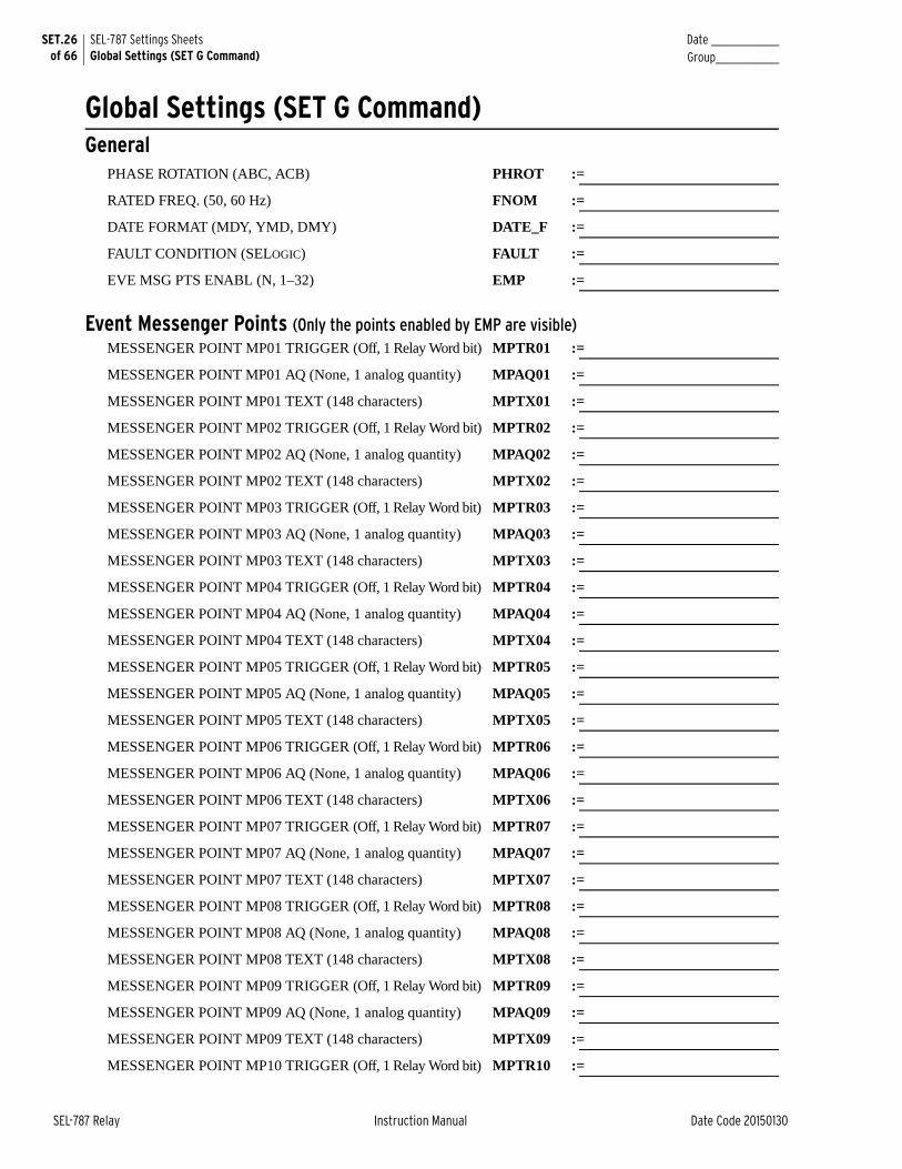
SET.26 of 66
SEL-787 Settings SheetsGlobal Settings (SET G Command)
Date _______________Group______________
SEL-787 Relay Instruction Manual Date Code 20150130
Global Settings (SET G Command)General
PHASE ROTATION (ABC, ACB) PHROT :=
RATED FREQ. (50, 60 Hz) FNOM :=
DATE FORMAT (MDY, YMD, DMY) DATE_F :=
FAULT CONDITION (SELOGIC) FAULT :=
EVE MSG PTS ENABL (N, 1–32) EMP :=
Event Messenger Points (Only the points enabled by EMP are visible)MESSENGER POINT MP01 TRIGGER (Off, 1 Relay Word bit) MPTR01 :=
MESSENGER POINT MP01 AQ (None, 1 analog quantity) MPAQ01 :=
MESSENGER POINT MP01 TEXT (148 characters) MPTX01 :=
MESSENGER POINT MP02 TRIGGER (Off, 1 Relay Word bit) MPTR02 :=
MESSENGER POINT MP02 AQ (None, 1 analog quantity) MPAQ02 :=
MESSENGER POINT MP02 TEXT (148 characters) MPTX02 :=
MESSENGER POINT MP03 TRIGGER (Off, 1 Relay Word bit) MPTR03 :=
MESSENGER POINT MP03 AQ (None, 1 analog quantity) MPAQ03 :=
MESSENGER POINT MP03 TEXT (148 characters) MPTX03 :=
MESSENGER POINT MP04 TRIGGER (Off, 1 Relay Word bit) MPTR04 :=
MESSENGER POINT MP04 AQ (None, 1 analog quantity) MPAQ04 :=
MESSENGER POINT MP04 TEXT (148 characters) MPTX04 :=
MESSENGER POINT MP05 TRIGGER (Off, 1 Relay Word bit) MPTR05 :=
MESSENGER POINT MP05 AQ (None, 1 analog quantity) MPAQ05 :=
MESSENGER POINT MP05 TEXT (148 characters) MPTX05 :=
MESSENGER POINT MP06 TRIGGER (Off, 1 Relay Word bit) MPTR06 :=
MESSENGER POINT MP06 AQ (None, 1 analog quantity) MPAQ06 :=
MESSENGER POINT MP06 TEXT (148 characters) MPTX06 :=
MESSENGER POINT MP07 TRIGGER (Off, 1 Relay Word bit) MPTR07 :=
MESSENGER POINT MP07 AQ (None, 1 analog quantity) MPAQ07 :=
MESSENGER POINT MP07 TEXT (148 characters) MPTX07 :=
MESSENGER POINT MP08 TRIGGER (Off, 1 Relay Word bit) MPTR08 :=
MESSENGER POINT MP08 AQ (None, 1 analog quantity) MPAQ08 :=
MESSENGER POINT MP08 TEXT (148 characters) MPTX08 :=
MESSENGER POINT MP09 TRIGGER (Off, 1 Relay Word bit) MPTR09 :=
MESSENGER POINT MP09 AQ (None, 1 analog quantity) MPAQ09 :=
MESSENGER POINT MP09 TEXT (148 characters) MPTX09 :=
MESSENGER POINT MP10 TRIGGER (Off, 1 Relay Word bit) MPTR10 :=
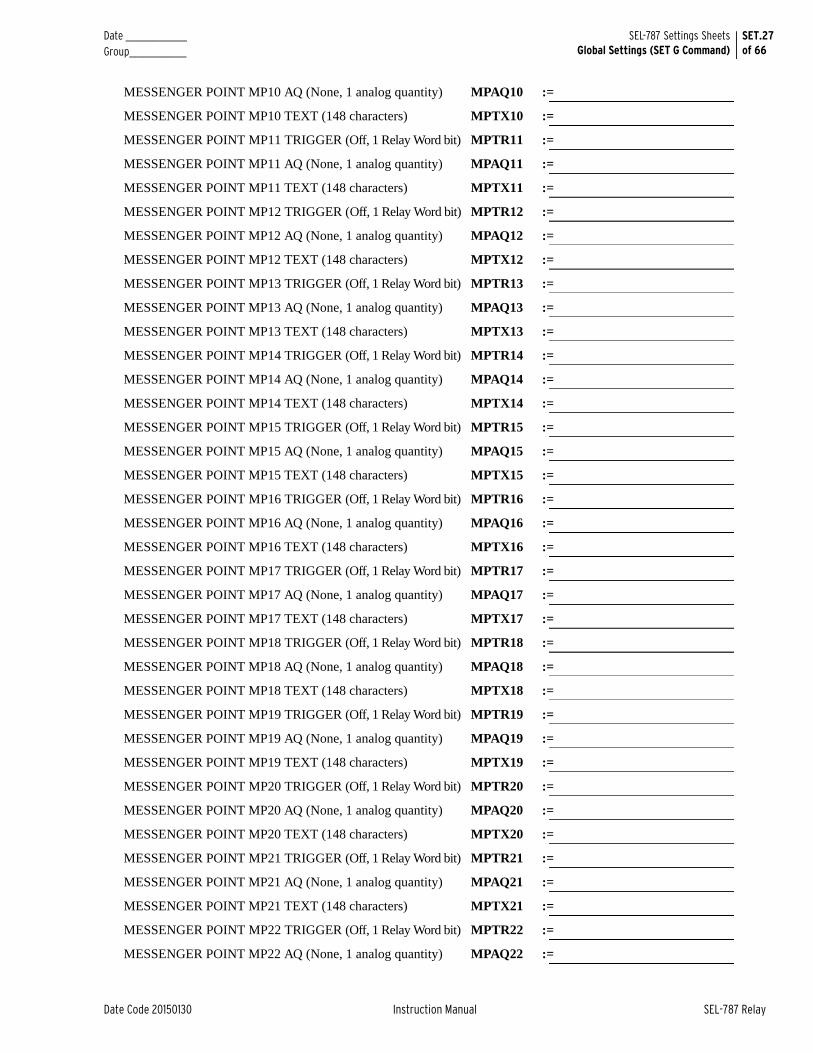
Date _______________ Group______________
SET.27of 66
SEL-787 Settings SheetsGlobal Settings (SET G Command)
Date Code 20150130 Instruction Manual SEL-787 Relay
MESSENGER POINT MP10 AQ (None, 1 analog quantity) MPAQ10 :=
MESSENGER POINT MP10 TEXT (148 characters) MPTX10 :=
MESSENGER POINT MP11 TRIGGER (Off, 1 Relay Word bit) MPTR11 :=
MESSENGER POINT MP11 AQ (None, 1 analog quantity) MPAQ11 :=
MESSENGER POINT MP11 TEXT (148 characters) MPTX11 :=
MESSENGER POINT MP12 TRIGGER (Off, 1 Relay Word bit) MPTR12 :=
MESSENGER POINT MP12 AQ (None, 1 analog quantity) MPAQ12 :=
MESSENGER POINT MP12 TEXT (148 characters) MPTX12 :=
MESSENGER POINT MP13 TRIGGER (Off, 1 Relay Word bit) MPTR13 :=
MESSENGER POINT MP13 AQ (None, 1 analog quantity) MPAQ13 :=
MESSENGER POINT MP13 TEXT (148 characters) MPTX13 :=
MESSENGER POINT MP14 TRIGGER (Off, 1 Relay Word bit) MPTR14 :=
MESSENGER POINT MP14 AQ (None, 1 analog quantity) MPAQ14 :=
MESSENGER POINT MP14 TEXT (148 characters) MPTX14 :=
MESSENGER POINT MP15 TRIGGER (Off, 1 Relay Word bit) MPTR15 :=
MESSENGER POINT MP15 AQ (None, 1 analog quantity) MPAQ15 :=
MESSENGER POINT MP15 TEXT (148 characters) MPTX15 :=
MESSENGER POINT MP16 TRIGGER (Off, 1 Relay Word bit) MPTR16 :=
MESSENGER POINT MP16 AQ (None, 1 analog quantity) MPAQ16 :=
MESSENGER POINT MP16 TEXT (148 characters) MPTX16 :=
MESSENGER POINT MP17 TRIGGER (Off, 1 Relay Word bit) MPTR17 :=
MESSENGER POINT MP17 AQ (None, 1 analog quantity) MPAQ17 :=
MESSENGER POINT MP17 TEXT (148 characters) MPTX17 :=
MESSENGER POINT MP18 TRIGGER (Off, 1 Relay Word bit) MPTR18 :=
MESSENGER POINT MP18 AQ (None, 1 analog quantity) MPAQ18 :=
MESSENGER POINT MP18 TEXT (148 characters) MPTX18 :=
MESSENGER POINT MP19 TRIGGER (Off, 1 Relay Word bit) MPTR19 :=
MESSENGER POINT MP19 AQ (None, 1 analog quantity) MPAQ19 :=
MESSENGER POINT MP19 TEXT (148 characters) MPTX19 :=
MESSENGER POINT MP20 TRIGGER (Off, 1 Relay Word bit) MPTR20 :=
MESSENGER POINT MP20 AQ (None, 1 analog quantity) MPAQ20 :=
MESSENGER POINT MP20 TEXT (148 characters) MPTX20 :=
MESSENGER POINT MP21 TRIGGER (Off, 1 Relay Word bit) MPTR21 :=
MESSENGER POINT MP21 AQ (None, 1 analog quantity) MPAQ21 :=
MESSENGER POINT MP21 TEXT (148 characters) MPTX21 :=
MESSENGER POINT MP22 TRIGGER (Off, 1 Relay Word bit) MPTR22 :=
MESSENGER POINT MP22 AQ (None, 1 analog quantity) MPAQ22 :=
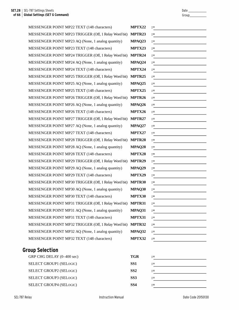
SET.28 of 66
SEL-787 Settings SheetsGlobal Settings (SET G Command)
Date _______________Group______________
SEL-787 Relay Instruction Manual Date Code 20150130
MESSENGER POINT MP22 TEXT (148 characters) MPTX22 :=
MESSENGER POINT MP23 TRIGGER (Off, 1 Relay Word bit) MPTR23 :=
MESSENGER POINT MP23 AQ (None, 1 analog quantity) MPAQ23 :=
MESSENGER POINT MP23 TEXT (148 characters) MPTX23 :=
MESSENGER POINT MP24 TRIGGER (Off, 1 Relay Word bit) MPTR24 :=
MESSENGER POINT MP24 AQ (None, 1 analog quantity) MPAQ24 :=
MESSENGER POINT MP24 TEXT (148 characters) MPTX24 :=
MESSENGER POINT MP25 TRIGGER (Off, 1 Relay Word bit) MPTR25 :=
MESSENGER POINT MP25 AQ (None, 1 analog quantity) MPAQ25 :=
MESSENGER POINT MP25 TEXT (148 characters) MPTX25 :=
MESSENGER POINT MP26 TRIGGER (Off, 1 Relay Word bit) MPTR26 :=
MESSENGER POINT MP26 AQ (None, 1 analog quantity) MPAQ26 :=
MESSENGER POINT MP26 TEXT (148 characters) MPTX26 :=
MESSENGER POINT MP27 TRIGGER (Off, 1 Relay Word bit) MPTR27 :=
MESSENGER POINT MP27 AQ (None, 1 analog quantity) MPAQ27 :=
MESSENGER POINT MP27 TEXT (148 characters) MPTX27 :=
MESSENGER POINT MP28 TRIGGER (Off, 1 Relay Word bit) MPTR28 :=
MESSENGER POINT MP28 AQ (None, 1 analog quantity) MPAQ28 :=
MESSENGER POINT MP28 TEXT (148 characters) MPTX28 :=
MESSENGER POINT MP29 TRIGGER (Off, 1 Relay Word bit) MPTR29 :=
MESSENGER POINT MP29 AQ (None, 1 analog quantity) MPAQ29 :=
MESSENGER POINT MP29 TEXT (148 characters) MPTX29 :=
MESSENGER POINT MP30 TRIGGER (Off, 1 Relay Word bit) MPTR30 :=
MESSENGER POINT MP30 AQ (None, 1 analog quantity) MPAQ30 :=
MESSENGER POINT MP30 TEXT (148 characters) MPTX30 :=
MESSENGER POINT MP31 TRIGGER (Off, 1 Relay Word bit) MPTR31 :=
MESSENGER POINT MP31 AQ (None, 1 analog quantity) MPAQ31 :=
MESSENGER POINT MP31 TEXT (148 characters) MPTX31 :=
MESSENGER POINT MP32 TRIGGER (Off, 1 Relay Word bit) MPTR32 :=
MESSENGER POINT MP32 AQ (None, 1 analog quantity) MPAQ32 :=
MESSENGER POINT MP32 TEXT (148 characters) MPTX32 :=
Group SelectionGRP CHG DELAY (0–400 sec) TGR :=
SELECT GROUP1 (SELOGIC) SS1 :=
SELECT GROUP2 (SELOGIC) SS2 :=
SELECT GROUP3 (SELOGIC) SS3 :=
SELECT GROUP4 (SELOGIC) SS4 :=
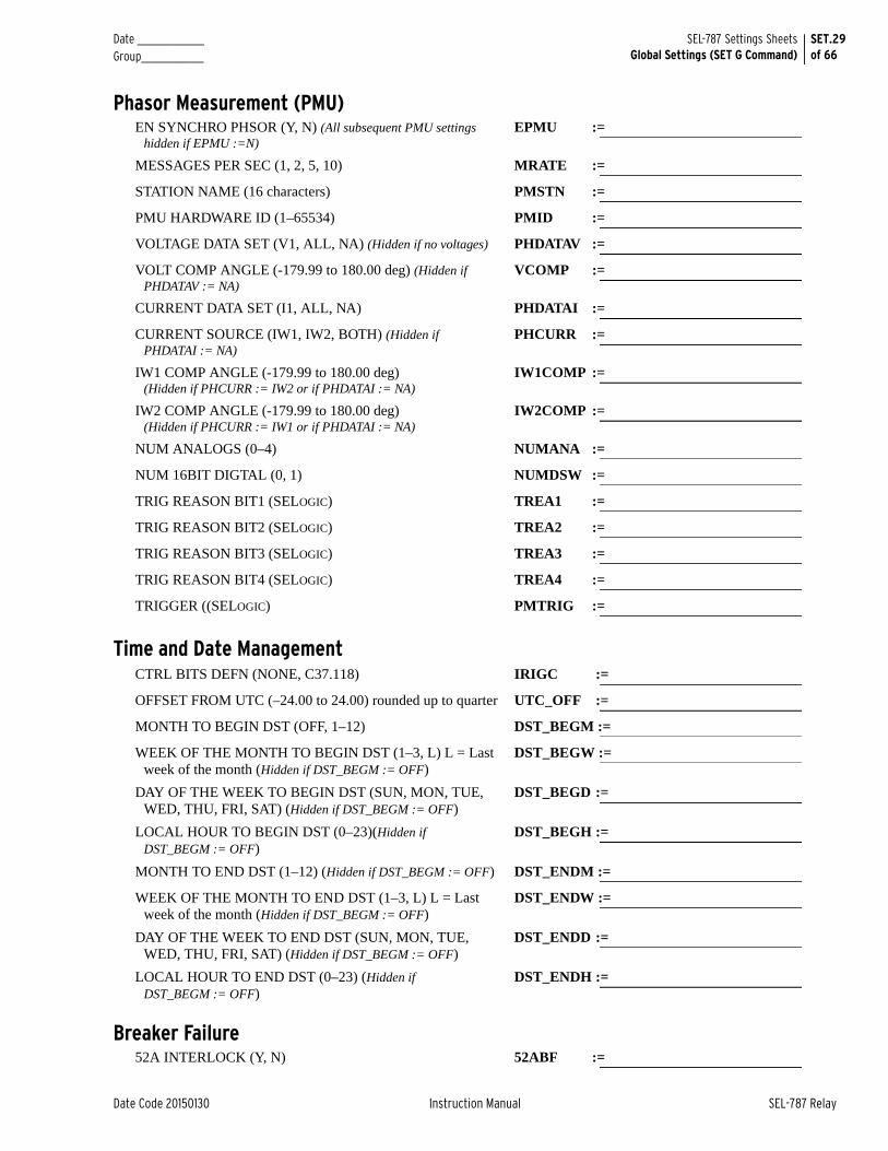
Date _______________ Group______________
SET.29of 66
SEL-787 Settings SheetsGlobal Settings (SET G Command)
Date Code 20150130 Instruction Manual SEL-787 Relay
Phasor Measurement (PMU)EN SYNCHRO PHSOR (Y, N) (All subsequent PMU settings
hidden if EPMU :=N)EPMU :=
MESSAGES PER SEC (1, 2, 5, 10) MRATE :=
STATION NAME (16 characters) PMSTN :=
PMU HARDWARE ID (1–65534) PMID :=
VOLTAGE DATA SET (V1, ALL, NA) (Hidden if no voltages) PHDATAV :=
VOLT COMP ANGLE (-179.99 to 180.00 deg) (Hidden if PHDATAV := NA)
VCOMP :=
CURRENT DATA SET (I1, ALL, NA) PHDATAI :=
CURRENT SOURCE (IW1, IW2, BOTH) (Hidden if PHDATAI := NA)
PHCURR :=
IW1 COMP ANGLE (-179.99 to 180.00 deg)(Hidden if PHCURR := IW2 or if PHDATAI := NA)
IW1COMP :=
IW2 COMP ANGLE (-179.99 to 180.00 deg)(Hidden if PHCURR := IW1 or if PHDATAI := NA)
IW2COMP :=
NUM ANALOGS (0–4) NUMANA :=
NUM 16BIT DIGTAL (0, 1) NUMDSW :=
TRIG REASON BIT1 (SELOGIC) TREA1 :=
TRIG REASON BIT2 (SELOGIC) TREA2 :=
TRIG REASON BIT3 (SELOGIC) TREA3 :=
TRIG REASON BIT4 (SELOGIC) TREA4 :=
TRIGGER ((SELOGIC) PMTRIG :=
Time and Date ManagementCTRL BITS DEFN (NONE, C37.118) IRIGC :=
OFFSET FROM UTC (–24.00 to 24.00) rounded up to quarter UTC_OFF :=
MONTH TO BEGIN DST (OFF, 1–12) DST_BEGM :=
WEEK OF THE MONTH TO BEGIN DST (1–3, L) L = Last week of the month (Hidden if DST_BEGM := OFF)
DST_BEGW :=
DAY OF THE WEEK TO BEGIN DST (SUN, MON, TUE, WED, THU, FRI, SAT) (Hidden if DST_BEGM := OFF)
DST_BEGD :=
LOCAL HOUR TO BEGIN DST (0–23)(Hidden if DST_BEGM := OFF)
DST_BEGH :=
MONTH TO END DST (1–12) (Hidden if DST_BEGM := OFF) DST_ENDM :=
WEEK OF THE MONTH TO END DST (1–3, L) L = Last week of the month (Hidden if DST_BEGM := OFF)
DST_ENDW :=
DAY OF THE WEEK TO END DST (SUN, MON, TUE, WED, THU, FRI, SAT) (Hidden if DST_BEGM := OFF)
DST_ENDD :=
LOCAL HOUR TO END DST (0–23) (Hidden if DST_BEGM := OFF)
DST_ENDH :=
Breaker Failure52A INTERLOCK (Y, N) 52ABF :=
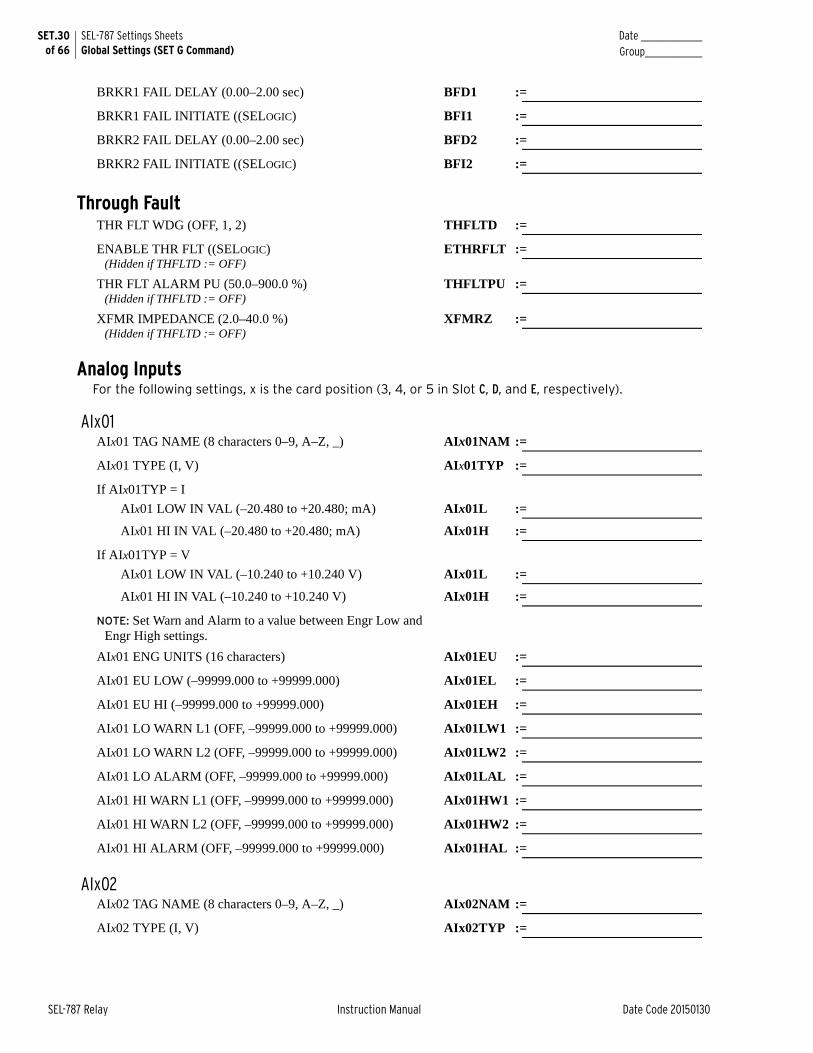
SET.30 of 66
SEL-787 Settings SheetsGlobal Settings (SET G Command)
Date _______________Group______________
SEL-787 Relay Instruction Manual Date Code 20150130
BRKR1 FAIL DELAY (0.00–2.00 sec) BFD1 :=
BRKR1 FAIL INITIATE ((SELOGIC) BFI1 :=
BRKR2 FAIL DELAY (0.00–2.00 sec) BFD2 :=
BRKR2 FAIL INITIATE ((SELOGIC) BFI2 :=
Through FaultTHR FLT WDG (OFF, 1, 2) THFLTD :=
ENABLE THR FLT ((SELOGIC) (Hidden if THFLTD := OFF)
ETHRFLT :=
THR FLT ALARM PU (50.0–900.0 %)(Hidden if THFLTD := OFF)
THFLTPU :=
XFMR IMPEDANCE (2.0–40.0 %)(Hidden if THFLTD := OFF)
XFMRZ :=
Analog InputsFor the following settings, x is the card position (3, 4, or 5 in Slot C, D, and E, respectively).
AIx01AIx01 TAG NAME (8 characters 0–9, A–Z, _) AIx01NAM :=
AIx01 TYPE (I, V) AIx01TYP :=
If AIx01TYP = I
AIx01 LOW IN VAL (–20.480 to +20.480; mA) AIx01L :=
AIx01 HI IN VAL (–20.480 to +20.480; mA) AIx01H :=
If AIx01TYP = V
AIx01 LOW IN VAL (–10.240 to +10.240 V) AIx01L :=
AIx01 HI IN VAL (–10.240 to +10.240 V) AIx01H :=
NOTE: Set Warn and Alarm to a value between Engr Low and Engr High settings.
AIx01 ENG UNITS (16 characters) AIx01EU :=
AIx01 EU LOW (–99999.000 to +99999.000) AIx01EL :=
AIx01 EU HI (–99999.000 to +99999.000) AIx01EH :=
AIx01 LO WARN L1 (OFF, –99999.000 to +99999.000) AIx01LW1 :=
AIx01 LO WARN L2 (OFF, –99999.000 to +99999.000) AIx01LW2 :=
AIx01 LO ALARM (OFF, –99999.000 to +99999.000) AIx01LAL :=
AIx01 HI WARN L1 (OFF, –99999.000 to +99999.000) AIx01HW1 :=
AIx01 HI WARN L2 (OFF, –99999.000 to +99999.000) AIx01HW2 :=
AIx01 HI ALARM (OFF, –99999.000 to +99999.000) AIx01HAL :=
AIx02AIx02 TAG NAME (8 characters 0–9, A–Z, _) AIx02NAM :=
AIx02 TYPE (I, V) AIx02TYP :=
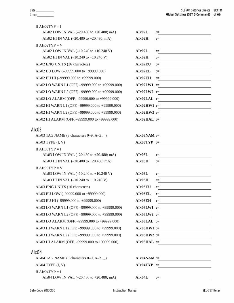
Date _______________ Group______________
SET.31of 66
SEL-787 Settings SheetsGlobal Settings (SET G Command)
Date Code 20150130 Instruction Manual SEL-787 Relay
If AIx02TYP = I
AIx02 LOW IN VAL (–20.480 to +20.480; mA) AIx02L :=
AIx02 HI IN VAL (–20.480 to +20.480; mA) AIx02H :=
If AIx02TYP = V
AIx02 LOW IN VAL (–10.240 to +10.240 V) AIx02L :=
AIx02 HI IN VAL (–10.240 to +10.240 V) AIx02H :=
AIx02 ENG UNITS (16 characters) AIx02EU :=
AIx02 EU LOW (–99999.000 to +99999.000) AIx02EL :=
AIx02 EU HI (–99999.000 to +99999.000) AIx02EH :=
AIx02 LO WARN L1 (OFF, –99999.000 to +99999.000) AIx02LW1 :=
AIx02 LO WARN L2 (OFF, –99999.000 to +99999.000) AIx02LW2 :=
AIx02 LO ALARM (OFF, –99999.000 to +99999.000) AIx02LAL :=
AIx02 HI WARN L1 (OFF, –99999.000 to +99999.000) AIx02HW1 :=
AIx02 HI WARN L2 (OFF, –99999.000 to +99999.000) AIx02HW2 :=
AIx02 HI ALARM (OFF, –99999.000 to +99999.000) AIx02HAL :=
AIx03AIx03 TAG NAME (8 characters 0–9, A–Z, _) AIx03NAM :=
AIx03 TYPE (I, V) AIx03TYP :=
If AIx03TYP = I
AIx03 LOW IN VAL (–20.480 to +20.480; mA) AIx03L :=
AIx03 HI IN VAL (–20.480 to +20.480; mA) AIx03H :=
If AIx03TYP = V
AIx03 LOW IN VAL (–10.240 to +10.240 V) AIx03L :=
AIx03 HI IN VAL (–10.240 to +10.240 V) AIx03H :=
AIx03 ENG UNITS (16 characters) AIx03EU :=
AIx03 EU LOW (–99999.000 to +99999.000) AIx03EL :=
AIx03 EU HI (–99999.000 to +99999.000) AIx03EH :=
AIx03 LO WARN L1 (OFF, –99999.000 to +99999.000) AIx03LW1 :=
AIx03 LO WARN L2 (OFF, –99999.000 to +99999.000) AIx03LW2 :=
AIx03 LO ALARM (OFF, –99999.000 to +99999.000) AIx03LAL :=
AIx03 HI WARN L1 (OFF, –99999.000 to +99999.000) AIx03HW1 :=
AIx03 HI WARN L2 (OFF, –99999.000 to +99999.000) AIx03HW2 :=
AIx03 HI ALARM (OFF, –99999.000 to +99999.000) AIx03HAL :=
AIx04AIx04 TAG NAME (8 characters 0–9, A–Z, _) AIx04NAM :=
AIx04 TYPE (I, V) AIx04TYP :=
If AIx04TYP = I
AIx04 LOW IN VAL (–20.480 to +20.480; mA) AIx04L :=
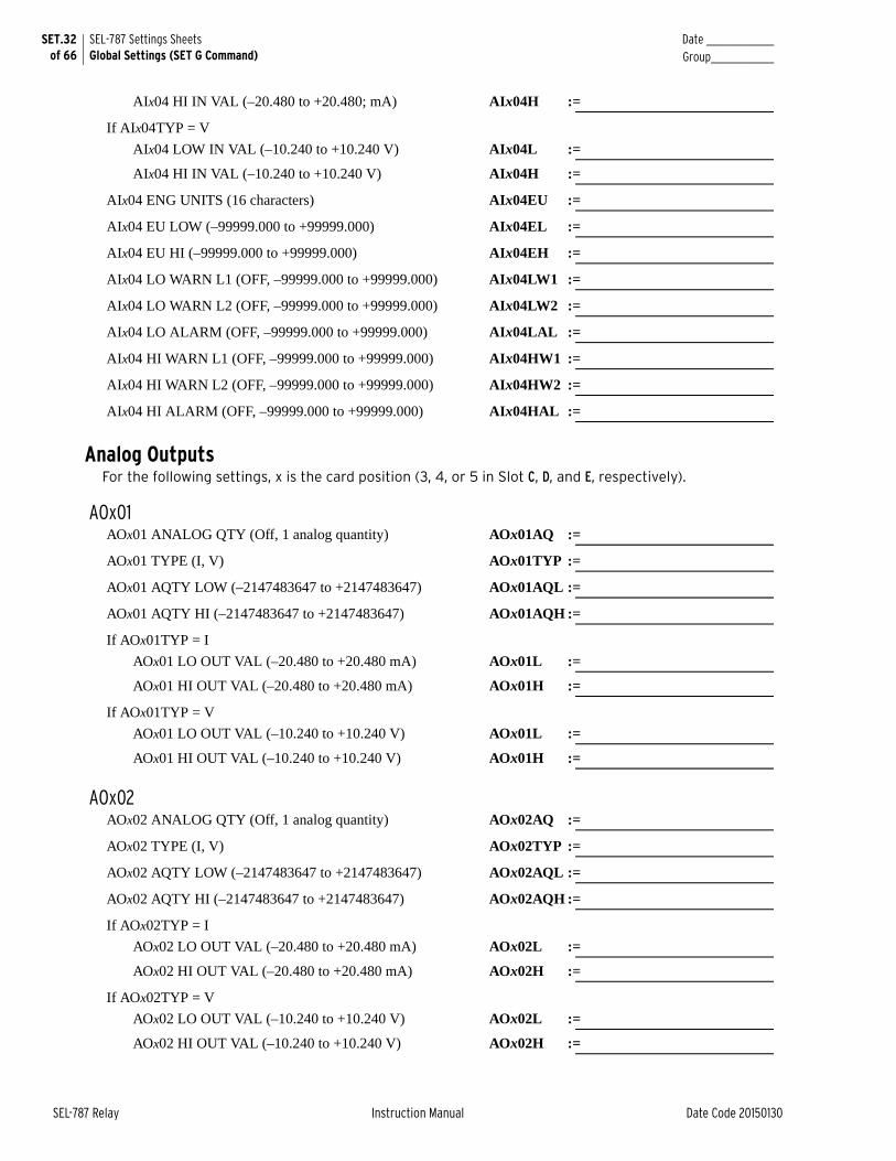
SET.32 of 66
SEL-787 Settings SheetsGlobal Settings (SET G Command)
Date _______________Group______________
SEL-787 Relay Instruction Manual Date Code 20150130
AIx04 HI IN VAL (–20.480 to +20.480; mA) AIx04H :=
If AIx04TYP = V
AIx04 LOW IN VAL (–10.240 to +10.240 V) AIx04L :=
AIx04 HI IN VAL (–10.240 to +10.240 V) AIx04H :=
AIx04 ENG UNITS (16 characters) AIx04EU :=
AIx04 EU LOW (–99999.000 to +99999.000) AIx04EL :=
AIx04 EU HI (–99999.000 to +99999.000) AIx04EH :=
AIx04 LO WARN L1 (OFF, –99999.000 to +99999.000) AIx04LW1 :=
AIx04 LO WARN L2 (OFF, –99999.000 to +99999.000) AIx04LW2 :=
AIx04 LO ALARM (OFF, –99999.000 to +99999.000) AIx04LAL :=
AIx04 HI WARN L1 (OFF, –99999.000 to +99999.000) AIx04HW1 :=
AIx04 HI WARN L2 (OFF, –99999.000 to +99999.000) AIx04HW2 :=
AIx04 HI ALARM (OFF, –99999.000 to +99999.000) AIx04HAL :=
Analog OutputsFor the following settings, x is the card position (3, 4, or 5 in Slot C, D, and E, respectively).
AOx01AOx01 ANALOG QTY (Off, 1 analog quantity) AOx01AQ :=
AOx01 TYPE (I, V) AOx01TYP :=
AOx01 AQTY LOW (–2147483647 to +2147483647) AOx01AQL :=
AOx01 AQTY HI (–2147483647 to +2147483647) AOx01AQH :=
If AOx01TYP = I
AOx01 LO OUT VAL (–20.480 to +20.480 mA) AOx01L :=
AOx01 HI OUT VAL (–20.480 to +20.480 mA) AOx01H :=
If AOx01TYP = V
AOx01 LO OUT VAL (–10.240 to +10.240 V) AOx01L :=
AOx01 HI OUT VAL (–10.240 to +10.240 V) AOx01H :=
AOx02AOx02 ANALOG QTY (Off, 1 analog quantity) AOx02AQ :=
AOx02 TYPE (I, V) AOx02TYP :=
AOx02 AQTY LOW (–2147483647 to +2147483647) AOx02AQL :=
AOx02 AQTY HI (–2147483647 to +2147483647) AOx02AQH :=
If AOx02TYP = I
AOx02 LO OUT VAL (–20.480 to +20.480 mA) AOx02L :=
AOx02 HI OUT VAL (–20.480 to +20.480 mA) AOx02H :=
If AOx02TYP = V
AOx02 LO OUT VAL (–10.240 to +10.240 V) AOx02L :=
AOx02 HI OUT VAL (–10.240 to +10.240 V) AOx02H :=

Date _______________ Group______________
SET.33of 66
SEL-787 Settings SheetsGlobal Settings (SET G Command)
Date Code 20150130 Instruction Manual SEL-787 Relay
AOx03AOx03 ANALOG QTY (Off, 1 analog quantity) AOx03AQ :=
AOx03 TYPE (I, V) AOx03TYP :=
AOx03 AQTY LOW (–2147483647 to +2147483647) AOx03AQL :=
AOx03 AQTY HI (–2147483647 to +2147483647) AOx03AQH :=
If AOx03TYP = I
AOx03 LO OUT VAL (–20.480 to +20.480 mA) AOx03L :=
AOx03 HI OUT VAL (–20.480 to +20.480 mA) AOx03H :=
If AOx03TYP = V
AOx03 LO OUT VAL (–10.240 to +10.240 V) AOx03L :=
AOx03 HI OUT VAL (–10.240 to +10.240 V) AOx03H :=
AOx04AOx04 ANALOG QTY (Off, 1 analog quantity) AOx04AQ :=
AOx04 TYPE (I, V) AOx04TYP :=
AOx04 AQTY LOW (–2147483647 to +2147483647) AOx04AQL :=
AOx04 AQTY HI (–2147483647 to +2147483647) AOx04AQH :=
If AOx04TYP = I
AOx04 LO OUT VAL (–20.480 to +20.480 mA) AOx04L :=
AOx04 HI OUT VAL (–20.480 to +20.480 mA) AOx04H :=
If AOx04TYP = V
AOx04 LO OUT VAL (–10.240 to +10.240 V) AOx04L :=
AOx04 HI OUT VAL (–10.240 to +10.240 V) AOx04H :=
Input Debounce Settings (Base Unit)IN101 Debounce (AC, 0–65000 ms) IN101D :=
IN102 Debounce (AC, 0–65000 ms) IN102D :=
Input Debounce Settings (Slot C)IN301 Debounce (AC, 0–65000 ms) IN301D :=
IN302 Debounce (AC, 0–65000 ms) IN302D :=
IN303 Debounce (AC, 0–65000 ms) IN303D :=
IN304 Debounce (AC, 0–65000 ms) IN304D :=
IN305 Debounce (AC, 0–65000 ms) IN305D :=
IN306 Debounce (AC, 0–65000 ms) IN306D :=
IN307 Debounce (AC, 0–65000 ms) IN307D :=
IN308 Debounce (AC, 0–65000 ms) IN308D :=
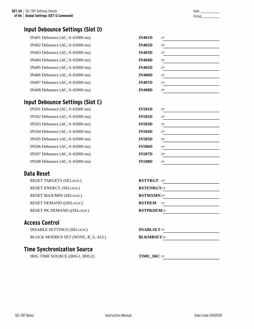
SET.34 of 66
SEL-787 Settings SheetsGlobal Settings (SET G Command)
Date _______________Group______________
SEL-787 Relay Instruction Manual Date Code 20150130
Input Debounce Settings (Slot D)IN401 Debounce (AC, 0–65000 ms) IN401D :=
IN402 Debounce (AC, 0–65000 ms) IN402D :=
IN403 Debounce (AC, 0–65000 ms) IN403D :=
IN404 Debounce (AC, 0–65000 ms) IN404D :=
IN405 Debounce (AC, 0–65000 ms) IN405D :=
IN406 Debounce (AC, 0–65000 ms) IN406D :=
IN407 Debounce (AC, 0–65000 ms) IN407D :=
IN408 Debounce (AC, 0–65000 ms) IN408D :=
Input Debounce Settings (Slot E)IN501 Debounce (AC, 0–65000 ms) IN501D :=
IN502 Debounce (AC, 0–65000 ms) IN502D :=
IN503 Debounce (AC, 0–65000 ms) IN503D :=
IN504 Debounce (AC, 0–65000 ms) IN504D :=
IN505 Debounce (AC, 0–65000 ms) IN505D :=
IN506 Debounce (AC, 0–65000 ms) IN506D :=
IN507 Debounce (AC, 0–65000 ms) IN507D :=
IN508 Debounce (AC, 0–65000 ms) IN508D :=
Data ResetRESET TARGETS (SELOGIC) RSTTRGT :=
RESET ENERGY (SELOGIC) RSTENRGY:=
RESET MAX/MIN (SELOGIC) RSTMXMN:=
RESET DEMAND ((SELOGIC) RSTDEM :=
RESET PK DEMAND ((SELOGIC) RSTPKDEM:=
Access ControlDISABLE SETTINGS (SELOGIC) DSABLSET :=
BLOCK MODBUS SET (NONE, R_S, ALL) BLKMBSET:=
Time Synchronization SourceIRIG TIME SOURCE (IRIG1, IRIG2) TIME_SRC :=
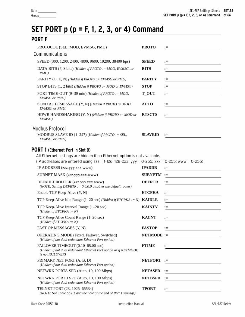
Date _______________ Group______________
SET.35of 66
SEL-787 Settings SheetsSET PORT p (p = F, 1, 2, 3, or 4) Command
Date Code 20150130 Instruction Manual SEL-787 Relay
SET PORT p (p = F, 1, 2, 3, or 4) CommandPORT F
PROTOCOL (SEL, MOD, EVMSG, PMU) PROTO :=
CommunicationsSPEED (300, 1200, 2400, 4800, 9600, 19200, 38400 bps) SPEED :=
DATA BITS (7, 8 bits) (Hidden if PROTO := MOD, EVMSG, or PMU)
BITS :=
PARITY (O, E, N) (Hidden if PROTO := EVMSG or PMU) PARITY :=
STOP BITS (1, 2 bits) (Hidden if PROTO := MOD or EVMSG) STOP :=
PORT TIME-OUT (0–30 min) (Hidden if PROTO := MOD, EVMSG or PMU)
T_OUT :=
SEND AUTOMESSAGE (Y, N) (Hidden if PROTO := MOD, EVMSG, or PMU)
AUTO :=
HDWR HANDSHAKING (Y, N) (Hidden if PROTO := MOD or EVMSG)
RTSCTS :=
Modbus ProtocolMODBUS SLAVE ID (1–247) (Hidden if PROTO := SEL,
EVMSG, or PMU)SLAVEID :=
PORT 1 (Ethernet Port in Slot B)All Ethernet settings are hidden if an Ethernet option is not available.
(IP addresses are entered using zzz = 1–126, 128–223; yyy = 0–255; xxx = 0–255; www = 0–255)
IP ADDRESS (zzz.yyy.xxx.www) IPADDR :=
SUBNET MASK (zzz.yyy.xxx.www) SUBNETM :=
DEFAULT ROUTER (zzz.yyy.xxx.www)(NOTE: Setting DEFRTR := 0.0.0.0 disables the default router)
DEFRTR :=
Enable TCP Keep-Alive (Y, N) ETCPKA :=
TCP Keep-Alive Idle Range (1–20 sec) (Hidden if ETCPKA := N) KAIDLE :=
TCP Keep-Alive Interval Range (1–20 sec) (Hidden if ETCPKA := N)
KAINTV :=
TCP Keep-Alive Count Range (1–20 sec) (Hidden if ETCPKA := N)
KACNT :=
FAST OP MESSAGES (Y, N) FASTOP :=
OPERATING MODE (Fixed, Failover, Switched) (Hidden if not dual redundant Ethernet Port option)
NETMODE :=
FAILOVER TIMEOUT (0.10–65.00 sec)(Hidden if not dual redundant Ethernet Port option or if NETMODE is not FAILOVER)
FTIME :=
PRIMARY NET PORT (A, B, D) (Hidden if not dual redundant Ethernet Port option)
NETPORT :=
NETWRK PORTA SPD (Auto, 10, 100 Mbps) NETASPD :=
NETWRK PORTB SPD (Auto, 10, 100 Mbps)(Hidden if not dual redundant Ethernet Port option)
NETBSPD :=
TELNET PORT (23, 1025–65534)(NOTE: See Table SET.1 and the note at the end of Port 1 settings)
TPORT :=
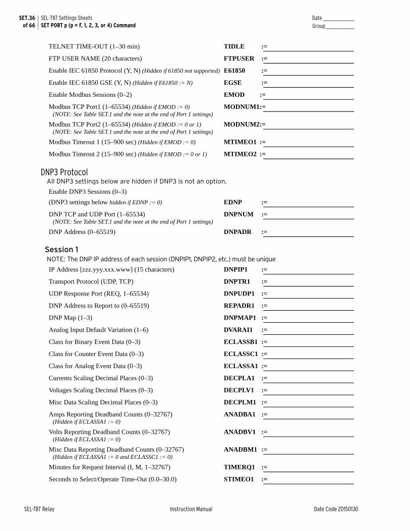
SET.36 of 66
SEL-787 Settings SheetsSET PORT p (p = F, 1, 2, 3, or 4) Command
Date _______________Group______________
SEL-787 Relay Instruction Manual Date Code 20150130
TELNET TIME-OUT (1–30 min) TIDLE :=
FTP USER NAME (20 characters) FTPUSER :=
Enable IEC 61850 Protocol (Y, N) (Hidden if 61850 not supported) E61850 :=
Enable IEC 61850 GSE (Y, N) (Hidden if E61850 := N) EGSE :=
Enable Modbus Sessions (0–2) EMOD :=
Modbus TCP Port1 (1–65534) (Hidden if EMOD := 0) (NOTE: See Table SET.1 and the note at the end of Port 1 settings)
MODNUM1:=
Modbus TCP Port2 (1–65534) (Hidden if EMOD := 0 or 1)(NOTE: See Table SET.1 and the note at the end of Port 1 settings)
MODNUM2:=
Modbus Timeout 1 (15–900 sec) (Hidden if EMOD := 0) MTIMEO1 :=
Modbus Timeout 2 (15–900 sec) (Hidden if EMOD := 0 or 1) MTIMEO2 :=
DNP3 ProtocolAll DNP3 settings below are hidden if DNP3 is not an option.
Enable DNP3 Sessions (0–3)
(DNP3 settings below hidden if EDNP := 0) EDNP :=
DNP TCP and UDP Port (1–65534)(NOTE: See Table SET.1 and the note at the end of Port 1 settings)
DNPNUM :=
DNP Address (0–65519) DNPADR :=
Session 1NOTE: The DNP IP address of each session (DNPIP1, DNPIP2, etc.) must be unique
IP Address [zzz.yyy.xxx.www] (15 characters) DNPIP1 :=
Transport Protocol (UDP, TCP) DNPTR1 :=
UDP Response Port (REQ, 1–65534) DNPUDP1 :=
DNP Address to Report to (0–65519) REPADR1 :=
DNP Map (1–3) DNPMAP1 :=
Analog Input Default Variation (1–6) DVARAI1 :=
Class for Binary Event Data (0–3) ECLASSB1 :=
Class for Counter Event Data (0–3) ECLASSC1 :=
Class for Analog Event Data (0–3) ECLASSA1 :=
Currents Scaling Decimal Places (0–3) DECPLA1 :=
Voltages Scaling Decimal Places (0–3) DECPLV1 :=
Misc Data Scaling Decimal Places (0–3) DECPLM1 :=
Amps Reporting Deadband Counts (0–32767)(Hidden if ECLASSA1 := 0)
ANADBA1 :=
Volts Reporting Deadband Counts (0–32767)(Hidden if ECLASSA1 := 0)
ANADBV1 :=
Misc Data Reporting Deadband Counts (0–32767)(Hidden if ECLASSA1 := 0 and ECLASSC1 := 0)
ANADBM1 :=
Minutes for Request Interval (I, M, 1–32767) TIMERQ1 :=
Seconds to Select/Operate Time-Out (0.0–30.0) STIMEO1 :=
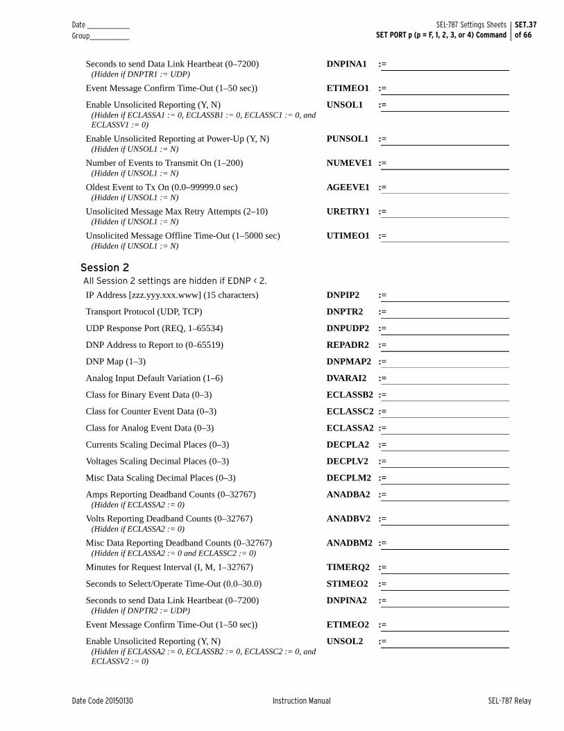
Date _______________ Group______________
SET.37of 66
SEL-787 Settings SheetsSET PORT p (p = F, 1, 2, 3, or 4) Command
Date Code 20150130 Instruction Manual SEL-787 Relay
Seconds to send Data Link Heartbeat (0–7200) (Hidden if DNPTR1 := UDP)
DNPINA1 :=
Event Message Confirm Time-Out (1–50 sec)) ETIMEO1 :=
Enable Unsolicited Reporting (Y, N)(Hidden if ECLASSA1 := 0, ECLASSB1 := 0, ECLASSC1 := 0, and ECLASSV1 := 0)
UNSOL1 :=
Enable Unsolicited Reporting at Power-Up (Y, N)(Hidden if UNSOL1 := N)
PUNSOL1 :=
Number of Events to Transmit On (1–200)(Hidden if UNSOL1 := N)
NUMEVE1 :=
Oldest Event to Tx On (0.0–99999.0 sec)(Hidden if UNSOL1 := N)
AGEEVE1 :=
Unsolicited Message Max Retry Attempts (2–10)(Hidden if UNSOL1 := N)
URETRY1 :=
Unsolicited Message Offline Time-Out (1–5000 sec)(Hidden if UNSOL1 := N)
UTIMEO1 :=
Session 2All Session 2 settings are hidden if EDNP < 2.
IP Address [zzz.yyy.xxx.www] (15 characters) DNPIP2 :=
Transport Protocol (UDP, TCP) DNPTR2 :=
UDP Response Port (REQ, 1–65534) DNPUDP2 :=
DNP Address to Report to (0–65519) REPADR2 :=
DNP Map (1–3) DNPMAP2 :=
Analog Input Default Variation (1–6) DVARAI2 :=
Class for Binary Event Data (0–3) ECLASSB2 :=
Class for Counter Event Data (0–3) ECLASSC2 :=
Class for Analog Event Data (0–3) ECLASSA2 :=
Currents Scaling Decimal Places (0–3) DECPLA2 :=
Voltages Scaling Decimal Places (0–3) DECPLV2 :=
Misc Data Scaling Decimal Places (0–3) DECPLM2 :=
Amps Reporting Deadband Counts (0–32767)(Hidden if ECLASSA2 := 0)
ANADBA2 :=
Volts Reporting Deadband Counts (0–32767)(Hidden if ECLASSA2 := 0)
ANADBV2 :=
Misc Data Reporting Deadband Counts (0–32767)(Hidden if ECLASSA2 := 0 and ECLASSC2 := 0)
ANADBM2 :=
Minutes for Request Interval (I, M, 1–32767) TIMERQ2 :=
Seconds to Select/Operate Time-Out (0.0–30.0) STIMEO2 :=
Seconds to send Data Link Heartbeat (0–7200)(Hidden if DNPTR2 := UDP)
DNPINA2 :=
Event Message Confirm Time-Out (1–50 sec)) ETIMEO2 :=
Enable Unsolicited Reporting (Y, N) (Hidden if ECLASSA2 := 0, ECLASSB2 := 0, ECLASSC2 := 0, and ECLASSV2 := 0)
UNSOL2 :=
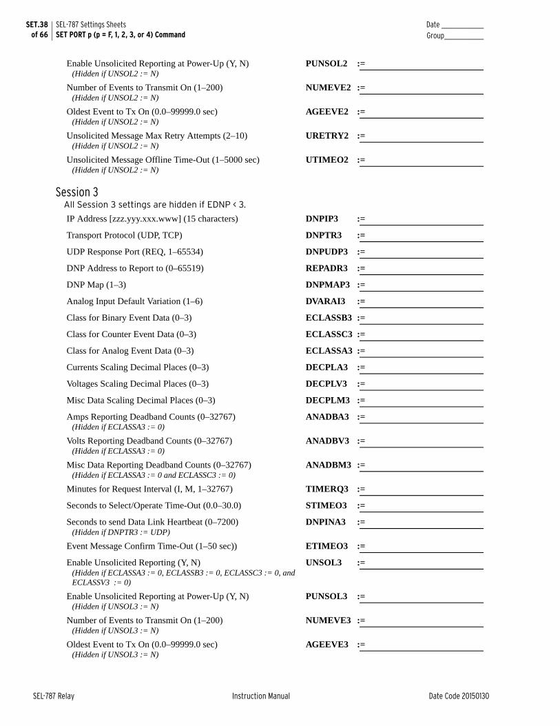
SET.38 of 66
SEL-787 Settings SheetsSET PORT p (p = F, 1, 2, 3, or 4) Command
Date _______________Group______________
SEL-787 Relay Instruction Manual Date Code 20150130
Enable Unsolicited Reporting at Power-Up (Y, N)(Hidden if UNSOL2 := N)
PUNSOL2 :=
Number of Events to Transmit On (1–200) (Hidden if UNSOL2 := N)
NUMEVE2 :=
Oldest Event to Tx On (0.0–99999.0 sec) (Hidden if UNSOL2 := N)
AGEEVE2 :=
Unsolicited Message Max Retry Attempts (2–10)(Hidden if UNSOL2 := N)
URETRY2 :=
Unsolicited Message Offline Time-Out (1–5000 sec)(Hidden if UNSOL2 := N)
UTIMEO2 :=
Session 3All Session 3 settings are hidden if EDNP < 3.
IP Address [zzz.yyy.xxx.www] (15 characters) DNPIP3 :=
Transport Protocol (UDP, TCP) DNPTR3 :=
UDP Response Port (REQ, 1–65534) DNPUDP3 :=
DNP Address to Report to (0–65519) REPADR3 :=
DNP Map (1–3) DNPMAP3 :=
Analog Input Default Variation (1–6) DVARAI3 :=
Class for Binary Event Data (0–3) ECLASSB3 :=
Class for Counter Event Data (0–3) ECLASSC3 :=
Class for Analog Event Data (0–3) ECLASSA3 :=
Currents Scaling Decimal Places (0–3) DECPLA3 :=
Voltages Scaling Decimal Places (0–3) DECPLV3 :=
Misc Data Scaling Decimal Places (0–3) DECPLM3 :=
Amps Reporting Deadband Counts (0–32767)(Hidden if ECLASSA3 := 0)
ANADBA3 :=
Volts Reporting Deadband Counts (0–32767)(Hidden if ECLASSA3 := 0)
ANADBV3 :=
Misc Data Reporting Deadband Counts (0–32767)(Hidden if ECLASSA3 := 0 and ECLASSC3 := 0)
ANADBM3 :=
Minutes for Request Interval (I, M, 1–32767) TIMERQ3 :=
Seconds to Select/Operate Time-Out (0.0–30.0) STIMEO3 :=
Seconds to send Data Link Heartbeat (0–7200)(Hidden if DNPTR3 := UDP)
DNPINA3 :=
Event Message Confirm Time-Out (1–50 sec)) ETIMEO3 :=
Enable Unsolicited Reporting (Y, N)(Hidden if ECLASSA3 := 0, ECLASSB3 := 0, ECLASSC3 := 0, and ECLASSV3 := 0)
UNSOL3 :=
Enable Unsolicited Reporting at Power-Up (Y, N)(Hidden if UNSOL3 := N)
PUNSOL3 :=
Number of Events to Transmit On (1–200)(Hidden if UNSOL3 := N)
NUMEVE3 :=
Oldest Event to Tx On (0.0–99999.0 sec)(Hidden if UNSOL3 := N)
AGEEVE3 :=
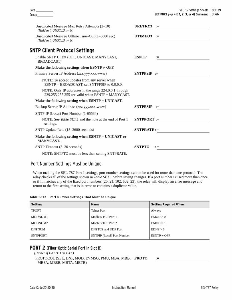
Date _______________ Group______________
SET.39of 66
SEL-787 Settings SheetsSET PORT p (p = F, 1, 2, 3, or 4) Command
Date Code 20150130 Instruction Manual SEL-787 Relay
Unsolicited Message Max Retry Attempts (2–10)(Hidden if UNSOL3 := N)
URETRY3 :=
Unsolicited Message Offline Time-Out (1–5000 sec)(Hidden if UNSOL3 := N)
UTIMEO3 :=
SNTP Client Protocol SettingsEnable SNTP Client (OFF, UNICAST, MANYCAST,
BROADCAST)ESNTP :=
Make the following settings when ESNTP OFF.
Primary Server IP Address (zzz.yyy.xxx.www) SNTPPSIP :=
NOTE: To accept updates from any server when ESNTP = BROADCAST, set SNTPPSIP to 0.0.0.0.
NOTE: Only IP addresses in the range 224.0.0.1 through 239.255.255.255 are valid when ESNTP = MANYCAST.
Make the following setting when ESNTP = UNICAST.
Backup Server IP Address (zzz.yyy.xxx.www) SNTPBSIP :=
SNTP IP (Local) Port Number (1-65534)
NOTE: See Table SET.1 and the note at the end of Port 1 settings.
SNTPPORT :=
SNTP Update Rate (15–3600 seconds) SNTPRATE: =
Make the following setting when ESNTP = UNICAST or MANYCAST.
SNTP Timeout (5–20 seconds) SNTPTO : =
NOTE: SNTPTO must be less than setting SNTPRATE.
Port Number Settings Must be Unique
When making the SEL-787 Port 1 settings, port number settings cannot be used for more than one protocol. The relay checks all of the settings shown in Table SET.1 before saving changes. If a port number is used more than once, or if it matches any of the fixed port numbers (20, 21, 102, 502, 23), the relay will display an error message and return to the first setting that is in error or contains a duplicate value.
PORT 2 (Fiber-Optic Serial Port in Slot B) (Hidden if E49RTD := EXT.)
PROTOCOL (SEL, DNP, MOD, EVMSG, PMU, MBA, MBB, MB8A, MB8B, MBTA, MBTB)
PROTO :=
Table SET.1 Port Number Settings That Must be Unique
Setting Name Setting Required When
TPORT Telnet Port Always
MODNUM1 Modbus TCP Port 1 EMOD > 0
MODNUM2 Modbus TCP Port 2 EMOD > 1
DNPNUM DNPTCP and UDP Port EDNP > 0
SNTPPORT SNTPIP (Local) Port Number ESNTP OFF
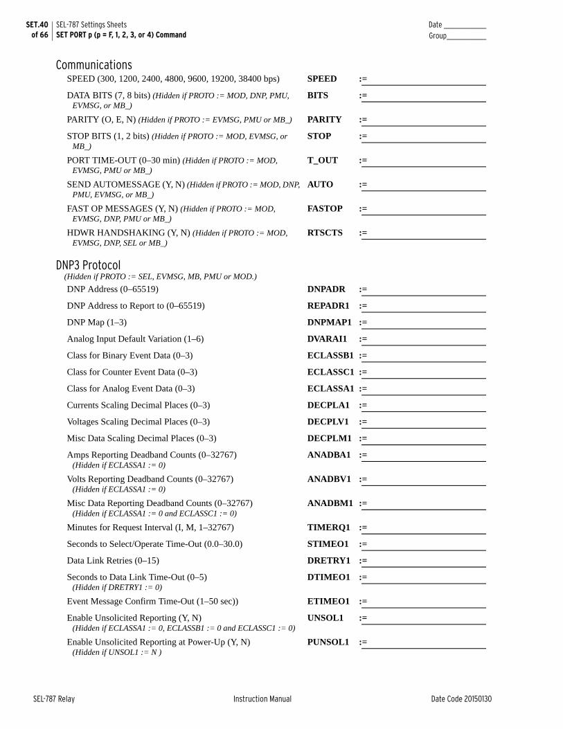
SET.40 of 66
SEL-787 Settings SheetsSET PORT p (p = F, 1, 2, 3, or 4) Command
Date _______________Group______________
SEL-787 Relay Instruction Manual Date Code 20150130
CommunicationsSPEED (300, 1200, 2400, 4800, 9600, 19200, 38400 bps) SPEED :=
DATA BITS (7, 8 bits) (Hidden if PROTO := MOD, DNP, PMU, EVMSG, or MB_)
BITS :=
PARITY (O, E, N) (Hidden if PROTO := EVMSG, PMU or MB_) PARITY :=
STOP BITS (1, 2 bits) (Hidden if PROTO := MOD, EVMSG, or MB_)
STOP :=
PORT TIME-OUT (0–30 min) (Hidden if PROTO := MOD, EVMSG, PMU or MB_)
T_OUT :=
SEND AUTOMESSAGE (Y, N) (Hidden if PROTO := MOD, DNP, PMU, EVMSG, or MB_)
AUTO :=
FAST OP MESSAGES (Y, N) (Hidden if PROTO := MOD, EVMSG, DNP, PMU or MB_)
FASTOP :=
HDWR HANDSHAKING (Y, N) (Hidden if PROTO := MOD, EVMSG, DNP, SEL or MB_)
RTSCTS :=
DNP3 Protocol(Hidden if PROTO := SEL, EVMSG, MB, PMU or MOD.)
DNP Address (0–65519) DNPADR :=
DNP Address to Report to (0–65519) REPADR1 :=
DNP Map (1–3) DNPMAP1 :=
Analog Input Default Variation (1–6) DVARAI1 :=
Class for Binary Event Data (0–3) ECLASSB1 :=
Class for Counter Event Data (0–3) ECLASSC1 :=
Class for Analog Event Data (0–3) ECLASSA1 :=
Currents Scaling Decimal Places (0–3) DECPLA1 :=
Voltages Scaling Decimal Places (0–3) DECPLV1 :=
Misc Data Scaling Decimal Places (0–3) DECPLM1 :=
Amps Reporting Deadband Counts (0–32767)(Hidden if ECLASSA1 := 0)
ANADBA1 :=
Volts Reporting Deadband Counts (0–32767)(Hidden if ECLASSA1 := 0)
ANADBV1 :=
Misc Data Reporting Deadband Counts (0–32767)(Hidden if ECLASSA1 := 0 and ECLASSC1 := 0)
ANADBM1 :=
Minutes for Request Interval (I, M, 1–32767) TIMERQ1 :=
Seconds to Select/Operate Time-Out (0.0–30.0) STIMEO1 :=
Data Link Retries (0–15) DRETRY1 :=
Seconds to Data Link Time-Out (0–5)(Hidden if DRETRY1 := 0)
DTIMEO1 :=
Event Message Confirm Time-Out (1–50 sec)) ETIMEO1 :=
Enable Unsolicited Reporting (Y, N)(Hidden if ECLASSA1 := 0, ECLASSB1 := 0 and ECLASSC1 := 0)
UNSOL1 :=
Enable Unsolicited Reporting at Power-Up (Y, N)(Hidden if UNSOL1 := N )
PUNSOL1 :=

Date _______________ Group______________
SET.41of 66
SEL-787 Settings SheetsSET PORT p (p = F, 1, 2, 3, or 4) Command
Date Code 20150130 Instruction Manual SEL-787 Relay
Number of Events to Transmit On (1–200)(Hidden if UNSOL1 := N)
NUMEVE1 :=
Oldest Event to Tx On (0.0–99999.0 sec)(Hidden if UNSOL1 := N)
AGEEVE1 :=
Unsolicited Message Max Retry Attempts (2–10)(Hidden if UNSOL1 := N)
URETRY1 :=
Unsolicited Message Offline Time-Out (1–5000 sec)(Hidden if UNSOL1 := N)
UTIMEO1 :=
Modbus ProtocolMODBUS SLAVE ID (1–247) (Hidden if PROTO := SEL, DNP,
PMU, EVMSG, or MB_)SLAVEID :=
MIRRORED BITS Protocol (Hidden if PROTO := SEL, EVMSG, DNP, PMU, or MOD.)
MB Transmit Identifier (1–4) TXID :=
MB Receive Identifier (1–4) RXID :=
MB RX Bad Pickup Time (0–10000 seconds) RBADPU :=
MB Channel Bad Pickup (1–10000 ppm) CBADPU :=
MB Receive Default State (8 characters) RXDFLT :=
RMB1 Pickup Debounce Messages (1–8) RMB1PU :=
RMB1 Dropout Debounce Messages (1–8) RMB1DO :=
RMB2 Pickup Debounce Messages (1–8) RMB2PU :=
RMB2 Dropout Debounce Messages (1–8) RMB2DO :=
RMB3 Pickup Debounce Messages (1–8) RMB3PU :=
RMB3 Dropout Debounce Messages (1–8) RMB3DO :=
RMB4 Pickup Debounce Messages (1–8) RMB4PU :=
RMB4 Dropout Debounce Messages (1–8) RMB4DO :=
RMB5 Pickup Debounce Messages (1–8) RMB5PU :=
RMB5 Dropout Debounce Messages (1–8) RMB5DO :=
RMB6 Pickup Debounce Messages (1–8) RMB6PU :=
RMB6 Dropout Debounce Messages (1–8) RMB6DO :=
RMB7 Pickup Debounce Messages (1–8) RMB7PU :=
RMB7 Dropout Debounce Messages (1–8) RMB7DO :=
RMB8 Pickup Debounce Messages (1–8) RMB8PU :=
RMB8 Dropout Debounce Messages (1–8) RMB8DO :=
PORT 3 (EIA-232 or EIA-485 Port in Slot B [ordering option])PROTOCOL (SEL, DNP, MOD, EVMSG, PMU, MBA, MBB,
MB8A, MB8B, MBTA, MBTB)PROTO :=
CommunicationsSPEED (300, 1200, 2400, 4800, 9600, 19200, 38400 bps) SPEED :=
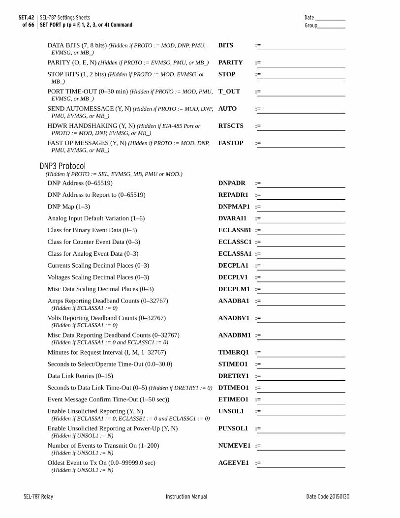
SET.42 of 66
SEL-787 Settings SheetsSET PORT p (p = F, 1, 2, 3, or 4) Command
Date _______________Group______________
SEL-787 Relay Instruction Manual Date Code 20150130
DATA BITS (7, 8 bits) (Hidden if PROTO := MOD, DNP, PMU, EVMSG, or MB_)
BITS :=
PARITY (O, E, N) (Hidden if PROTO := EVMSG, PMU, or MB_) PARITY :=
STOP BITS (1, 2 bits) (Hidden if PROTO := MOD, EVMSG, or MB_)
STOP :=
PORT TIME-OUT (0–30 min) (Hidden if PROTO := MOD, PMU, EVMSG, or MB_)
T_OUT :=
SEND AUTOMESSAGE (Y, N) (Hidden if PROTO := MOD, DNP, PMU, EVMSG, or MB_)
AUTO :=
HDWR HANDSHAKING (Y, N) (Hidden if EIA-485 Port or PROTO := MOD, DNP, EVMSG, or MB_)
RTSCTS :=
FAST OP MESSAGES (Y, N) (Hidden if PROTO := MOD, DNP, PMU, EVMSG, or MB_)
FASTOP :=
DNP3 Protocol(Hidden if PROTO := SEL, EVMSG, MB, PMU or MOD.)
DNP Address (0–65519) DNPADR :=
DNP Address to Report to (0–65519) REPADR1 :=
DNP Map (1–3) DNPMAP1 :=
Analog Input Default Variation (1–6) DVARAI1 :=
Class for Binary Event Data (0–3) ECLASSB1 :=
Class for Counter Event Data (0–3) ECLASSC1 :=
Class for Analog Event Data (0–3) ECLASSA1 :=
Currents Scaling Decimal Places (0–3) DECPLA1 :=
Voltages Scaling Decimal Places (0–3) DECPLV1 :=
Misc Data Scaling Decimal Places (0–3) DECPLM1 :=
Amps Reporting Deadband Counts (0–32767)(Hidden if ECLASSA1 := 0)
ANADBA1 :=
Volts Reporting Deadband Counts (0–32767)(Hidden if ECLASSA1 := 0)
ANADBV1 :=
Misc Data Reporting Deadband Counts (0–32767)(Hidden if ECLASSA1 := 0 and ECLASSC1 := 0)
ANADBM1 :=
Minutes for Request Interval (I, M, 1–32767) TIMERQ1 :=
Seconds to Select/Operate Time-Out (0.0–30.0) STIMEO1 :=
Data Link Retries (0–15) DRETRY1 :=
Seconds to Data Link Time-Out (0–5) (Hidden if DRETRY1 := 0) DTIMEO1 :=
Event Message Confirm Time-Out (1–50 sec)) ETIMEO1 :=
Enable Unsolicited Reporting (Y, N)(Hidden if ECLASSA1 := 0, ECLASSB1 := 0 and ECLASSC1 := 0)
UNSOL1 :=
Enable Unsolicited Reporting at Power-Up (Y, N)(Hidden if UNSOL1 := N)
PUNSOL1 :=
Number of Events to Transmit On (1–200)(Hidden if UNSOL1 := N)
NUMEVE1 :=
Oldest Event to Tx On (0.0–99999.0 sec)(Hidden if UNSOL1 := N)
AGEEVE1 :=
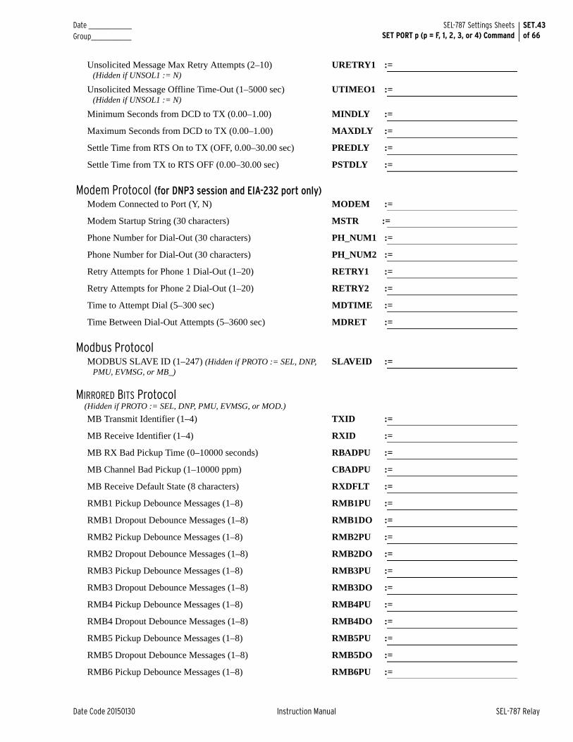
Date _______________ Group______________
SET.43of 66
SEL-787 Settings SheetsSET PORT p (p = F, 1, 2, 3, or 4) Command
Date Code 20150130 Instruction Manual SEL-787 Relay
Unsolicited Message Max Retry Attempts (2–10)(Hidden if UNSOL1 := N)
URETRY1 :=
Unsolicited Message Offline Time-Out (1–5000 sec)(Hidden if UNSOL1 := N)
UTIMEO1 :=
Minimum Seconds from DCD to TX (0.00–1.00) MINDLY :=
Maximum Seconds from DCD to TX (0.00–1.00) MAXDLY :=
Settle Time from RTS On to TX (OFF, 0.00–30.00 sec) PREDLY :=
Settle Time from TX to RTS OFF (0.00–30.00 sec) PSTDLY :=
Modem Protocol (for DNP3 session and EIA-232 port only)Modem Connected to Port (Y, N) MODEM :=
Modem Startup String (30 characters) MSTR :=
Phone Number for Dial-Out (30 characters) PH_NUM1 :=
Phone Number for Dial-Out (30 characters) PH_NUM2 :=
Retry Attempts for Phone 1 Dial-Out (1–20) RETRY1 :=
Retry Attempts for Phone 2 Dial-Out (1–20) RETRY2 :=
Time to Attempt Dial (5–300 sec) MDTIME :=
Time Between Dial-Out Attempts (5–3600 sec) MDRET :=
Modbus ProtocolMODBUS SLAVE ID (1–247) (Hidden if PROTO := SEL, DNP,
PMU, EVMSG, or MB_)SLAVEID :=
MIRRORED BITS Protocol (Hidden if PROTO := SEL, DNP, PMU, EVMSG, or MOD.)
MB Transmit Identifier (1–4) TXID :=
MB Receive Identifier (1–4) RXID :=
MB RX Bad Pickup Time (0–10000 seconds) RBADPU :=
MB Channel Bad Pickup (1–10000 ppm) CBADPU :=
MB Receive Default State (8 characters) RXDFLT :=
RMB1 Pickup Debounce Messages (1–8) RMB1PU :=
RMB1 Dropout Debounce Messages (1–8) RMB1DO :=
RMB2 Pickup Debounce Messages (1–8) RMB2PU :=
RMB2 Dropout Debounce Messages (1–8) RMB2DO :=
RMB3 Pickup Debounce Messages (1–8) RMB3PU :=
RMB3 Dropout Debounce Messages (1–8) RMB3DO :=
RMB4 Pickup Debounce Messages (1–8) RMB4PU :=
RMB4 Dropout Debounce Messages (1–8) RMB4DO :=
RMB5 Pickup Debounce Messages (1–8) RMB5PU :=
RMB5 Dropout Debounce Messages (1–8) RMB5DO :=
RMB6 Pickup Debounce Messages (1–8) RMB6PU :=
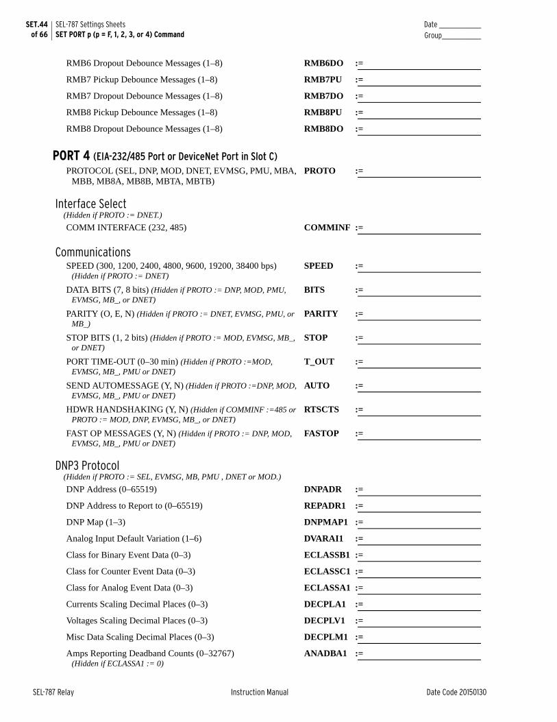
SET.44 of 66
SEL-787 Settings SheetsSET PORT p (p = F, 1, 2, 3, or 4) Command
Date _______________Group______________
SEL-787 Relay Instruction Manual Date Code 20150130
RMB6 Dropout Debounce Messages (1–8) RMB6DO :=
RMB7 Pickup Debounce Messages (1–8) RMB7PU :=
RMB7 Dropout Debounce Messages (1–8) RMB7DO :=
RMB8 Pickup Debounce Messages (1–8) RMB8PU :=
RMB8 Dropout Debounce Messages (1–8) RMB8DO :=
PORT 4 (EIA-232/485 Port or DeviceNet Port in Slot C)PROTOCOL (SEL, DNP, MOD, DNET, EVMSG, PMU, MBA,
MBB, MB8A, MB8B, MBTA, MBTB)PROTO :=
Interface Select(Hidden if PROTO := DNET.)
COMM INTERFACE (232, 485) COMMINF :=
CommunicationsSPEED (300, 1200, 2400, 4800, 9600, 19200, 38400 bps)
(Hidden if PROTO := DNET)SPEED :=
DATA BITS (7, 8 bits) (Hidden if PROTO := DNP, MOD, PMU, EVMSG, MB_, or DNET)
BITS :=
PARITY (O, E, N) (Hidden if PROTO := DNET, EVMSG, PMU, or MB_)
PARITY :=
STOP BITS (1, 2 bits) (Hidden if PROTO := MOD, EVMSG, MB_, or DNET)
STOP :=
PORT TIME-OUT (0–30 min) (Hidden if PROTO :=MOD, EVMSG, MB_, PMU or DNET)
T_OUT :=
SEND AUTOMESSAGE (Y, N) (Hidden if PROTO :=DNP, MOD, EVMSG, MB_, PMU or DNET)
AUTO :=
HDWR HANDSHAKING (Y, N) (Hidden if COMMINF :=485 or PROTO := MOD, DNP, EVMSG, MB_, or DNET)
RTSCTS :=
FAST OP MESSAGES (Y, N) (Hidden if PROTO := DNP, MOD, EVMSG, MB_, PMU or DNET)
FASTOP :=
DNP3 Protocol(Hidden if PROTO := SEL, EVMSG, MB, PMU , DNET or MOD.)
DNP Address (0–65519) DNPADR :=
DNP Address to Report to (0–65519) REPADR1 :=
DNP Map (1–3) DNPMAP1 :=
Analog Input Default Variation (1–6) DVARAI1 :=
Class for Binary Event Data (0–3) ECLASSB1 :=
Class for Counter Event Data (0–3) ECLASSC1 :=
Class for Analog Event Data (0–3) ECLASSA1 :=
Currents Scaling Decimal Places (0–3) DECPLA1 :=
Voltages Scaling Decimal Places (0–3) DECPLV1 :=
Misc Data Scaling Decimal Places (0–3) DECPLM1 :=
Amps Reporting Deadband Counts (0–32767)(Hidden if ECLASSA1 := 0)
ANADBA1 :=
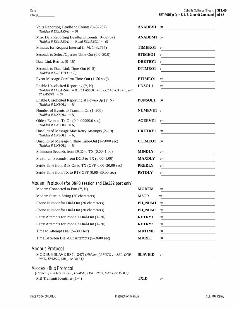
Date _______________ Group______________
SET.45of 66
SEL-787 Settings SheetsSET PORT p (p = F, 1, 2, 3, or 4) Command
Date Code 20150130 Instruction Manual SEL-787 Relay
Volts Reporting Deadband Counts (0–32767)(Hidden if ECLASSA1 := 0)
ANADBV1 :=
Misc Data Reporting Deadband Counts (0–32767)(Hidden if ECLASSA1 := 0 and ECLASSC1 := 0)
ANADBM1 :=
Minutes for Request Interval (I, M, 1–32767) TIMERQ1 :=
Seconds to Select/Operate Time-Out (0.0–30.0) STIMEO1 :=
Data Link Retries (0–15) DRETRY1 :=
Seconds to Data Link Time-Out (0–5)(Hidden if DRETRY1 := 0)
DTIMEO1 :=
Event Message Confirm Time-Out (1–50 sec)) ETIMEO1 :=
Enable Unsolicited Reporting (Y, N)(Hidden if ECLASSA1 := 0, ECLASSB1 := 0, ECLASSC1 := 0, and ECLASSV1 := 0)
UNSOL1 :=
Enable Unsolicited Reporting at Power-Up (Y, N)(Hidden if UNSOL1 := N)
PUNSOL1 :=
Number of Events to Transmit On (1–200)(Hidden if UNSOL1 := N)
NUMEVE1 :=
Oldest Event to Tx On (0.0–99999.0 sec)(Hidden if UNSOL1 := N)
AGEEVE1 :=
Unsolicited Message Max Retry Attempts (2–10)(Hidden if UNSOL1 := N)
URETRY1 :=
Unsolicited Message Offline Time-Out (1–5000 sec)(Hidden if UNSOL1 := N)
UTIMEO1 :=
Minimum Seconds from DCD to TX (0.00–1.00) MINDLY :=
Maximum Seconds from DCD to TX (0.00–1.00) MAXDLY :=
Settle Time from RTS On to TX (OFF, 0.00–30.00 sec) PREDLY :=
Settle Time from TX to RTS OFF (0.00–30.00 sec) PSTDLY :=
Modem Protocol (for DNP3 session and EIA232 port only)Modem Connected to Port (Y, N) MODEM :=
Modem Startup String (30 characters) MSTR :=
Phone Number for Dial-Out (30 characters) PH_NUM1 :=
Phone Number for Dial-Out (30 characters) PH_NUM2 :=
Retry Attempts for Phone 1 Dial-Out (1–20) RETRY1 :=
Retry Attempts for Phone 2 Dial-Out (1–20) RETRY2 :=
Time to Attempt Dial (5–300 sec) MDTIME :=
Time Between Dial-Out Attempts (5–3600 sec) MDRET :=
Modbus ProtocolMODBUS SLAVE ID (1–247) (Hidden if PROTO := SEL, DNP,
PMU, EVMSG, MB_, or DNET)SLAVEID :=
MIRRORED BITS Protocol (Hidden if PROTO := SEL, EVMSG, DNP, PMU, DNET or MOD.)
MB Transmit Identifier (1–4) TXID :=
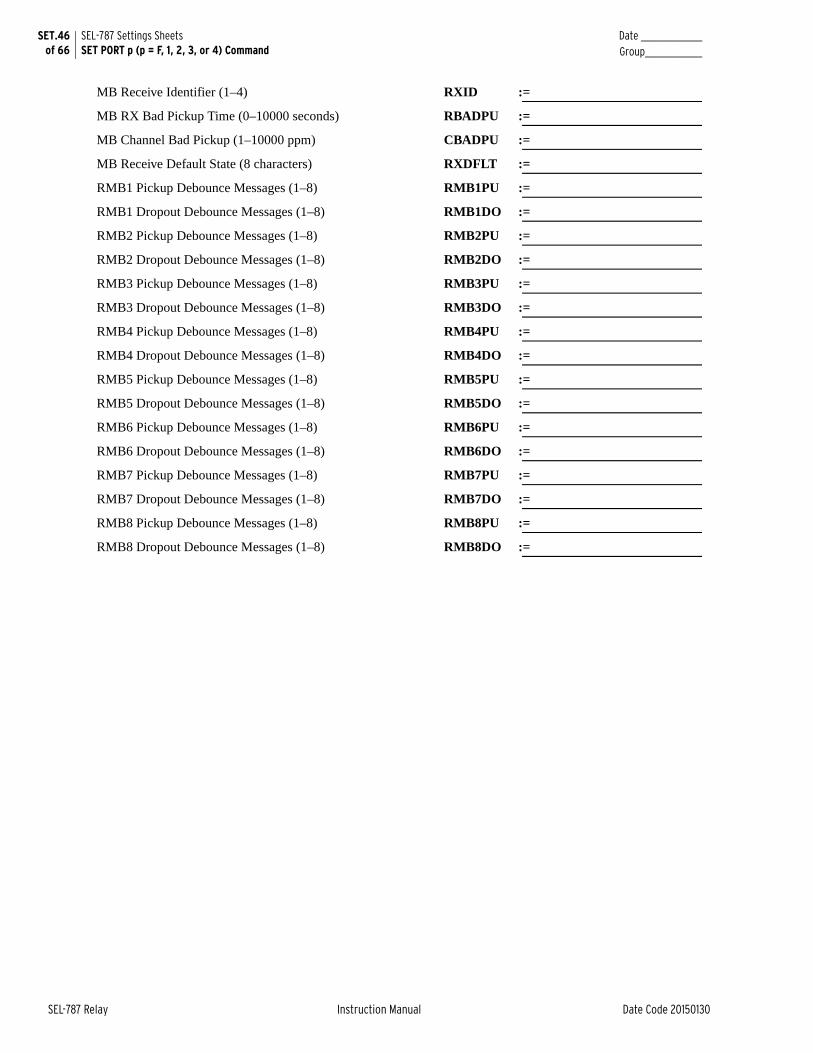
SET.46 of 66
SEL-787 Settings SheetsSET PORT p (p = F, 1, 2, 3, or 4) Command
Date _______________Group______________
SEL-787 Relay Instruction Manual Date Code 20150130
MB Receive Identifier (1–4) RXID :=
MB RX Bad Pickup Time (0–10000 seconds) RBADPU :=
MB Channel Bad Pickup (1–10000 ppm) CBADPU :=
MB Receive Default State (8 characters) RXDFLT :=
RMB1 Pickup Debounce Messages (1–8) RMB1PU :=
RMB1 Dropout Debounce Messages (1–8) RMB1DO :=
RMB2 Pickup Debounce Messages (1–8) RMB2PU :=
RMB2 Dropout Debounce Messages (1–8) RMB2DO :=
RMB3 Pickup Debounce Messages (1–8) RMB3PU :=
RMB3 Dropout Debounce Messages (1–8) RMB3DO :=
RMB4 Pickup Debounce Messages (1–8) RMB4PU :=
RMB4 Dropout Debounce Messages (1–8) RMB4DO :=
RMB5 Pickup Debounce Messages (1–8) RMB5PU :=
RMB5 Dropout Debounce Messages (1–8) RMB5DO :=
RMB6 Pickup Debounce Messages (1–8) RMB6PU :=
RMB6 Dropout Debounce Messages (1–8) RMB6DO :=
RMB7 Pickup Debounce Messages (1–8) RMB7PU :=
RMB7 Dropout Debounce Messages (1–8) RMB7DO :=
RMB8 Pickup Debounce Messages (1–8) RMB8PU :=
RMB8 Dropout Debounce Messages (1–8) RMB8DO :=
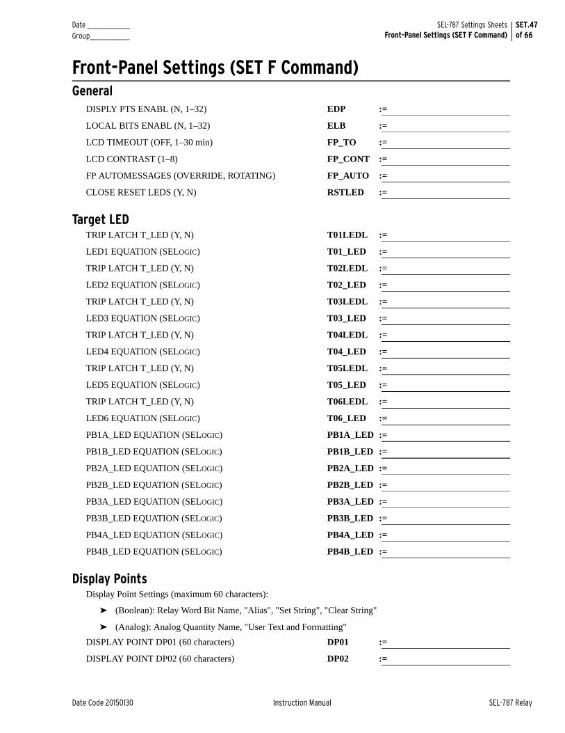
Date _______________ Group______________
SET.47of 66
SEL-787 Settings SheetsFront-Panel Settings (SET F Command)
Date Code 20150130 Instruction Manual SEL-787 Relay
Front-Panel Settings (SET F Command)General
DISPLY PTS ENABL (N, 1–32) EDP :=
LOCAL BITS ENABL (N, 1–32) ELB :=
LCD TIMEOUT (OFF, 1–30 min) FP_TO :=
LCD CONTRAST (1–8) FP_CONT :=
FP AUTOMESSAGES (OVERRIDE, ROTATING) FP_AUTO :=
CLOSE RESET LEDS (Y, N) RSTLED :=
Target LEDTRIP LATCH T_LED (Y, N) T01LEDL :=
LED1 EQUATION (SELOGIC) T01_LED :=
TRIP LATCH T_LED (Y, N) T02LEDL :=
LED2 EQUATION (SELOGIC) T02_LED :=
TRIP LATCH T_LED (Y, N) T03LEDL :=
LED3 EQUATION (SELOGIC) T03_LED :=
TRIP LATCH T_LED (Y, N) T04LEDL :=
LED4 EQUATION (SELOGIC) T04_LED :=
TRIP LATCH T_LED (Y, N) T05LEDL :=
LED5 EQUATION (SELOGIC) T05_LED :=
TRIP LATCH T_LED (Y, N) T06LEDL :=
LED6 EQUATION (SELOGIC) T06_LED :=
PB1A_LED EQUATION (SELOGIC) PB1A_LED :=
PB1B_LED EQUATION (SELOGIC) PB1B_LED :=
PB2A_LED EQUATION (SELOGIC) PB2A_LED :=
PB2B_LED EQUATION (SELOGIC) PB2B_LED :=
PB3A_LED EQUATION (SELOGIC) PB3A_LED :=
PB3B_LED EQUATION (SELOGIC) PB3B_LED :=
PB4A_LED EQUATION (SELOGIC) PB4A_LED :=
PB4B_LED EQUATION (SELOGIC) PB4B_LED :=
Display PointsDisplay Point Settings (maximum 60 characters):
➤ (Boolean): Relay Word Bit Name, "Alias", "Set String", "Clear String"
➤ (Analog): Analog Quantity Name, "User Text and Formatting"
DISPLAY POINT DP01 (60 characters) DP01 :=
DISPLAY POINT DP02 (60 characters) DP02 :=
SET.48 of 66
SEL-787 Settings SheetsFront-Panel Settings (SET F Command)
Date _______________Group______________
SEL-787 Relay Instruction Manual Date Code 20150130
DISPLAY POINT DP03 (60 characters) DP03 :=
DISPLAY POINT DP04 (60 characters) DP04 :=
DISPLAY POINT DP05 (60 characters) DP05 :=
DISPLAY POINT DP06 (60 characters) DP06 :=
DISPLAY POINT DP07 (60 characters) DP07 :=
DISPLAY POINT DP08 (60 characters) DP08 :=
DISPLAY POINT DP09 (60 characters) DP09 :=
DISPLAY POINT DP10 (60 characters) DP10 :=
DISPLAY POINT DP11 (60 characters) DP11 :=
DISPLAY POINT DP12 (60 characters) DP12 :=
DISPLAY POINT DP13 (60 characters) DP13 :=
DISPLAY POINT DP14 (60 characters) DP14 :=
DISPLAY POINT DP15 (60 characters) DP15 :=
DISPLAY POINT DP16 (60 characters) DP16 :=
DISPLAY POINT DP17 (60 characters) DP17 :=
DISPLAY POINT DP18 (60 characters) DP18 :=
DISPLAY POINT DP19 (60 characters) DP19 :=
DISPLAY POINT DP20 (60 characters) DP20 :=
DISPLAY POINT DP21 (60 characters) DP21 :=
DISPLAY POINT DP22 (60 characters) DP22 :=
DISPLAY POINT DP23 (60 characters) DP23 :=
DISPLAY POINT DP24 (60 characters) DP24 :=
DISPLAY POINT DP25 (60 characters) DP25 :=
DISPLAY POINT DP26 (60 characters) DP26 :=
DISPLAY POINT DP27 (60 characters) DP27 :=
DISPLAY POINT DP28 (60 characters) DP28 :=
DISPLAY POINT DP29 (60 characters) DP29 :=
DISPLAY POINT DP30 (60 characters) DP30 :=
DISPLAY POINT DP31 (60 characters) DP31 :=
DISPLAY POINT DP32 (60 characters) DP32 :=
Local Bits LabelsLB_NAME (14 characters) NLB01 :=
CLEAR LB_ LABEL (7 characters) CLB01 :=
SET LB_ LABEL (7 characters) SLB01 :=
PULSE LB_ LABEL (7 characters) PLB01 :=
LB_NAME (14 characters) NLB02 :=
CLEAR LB_ LABEL (7 characters) CLB02 :=
Date _______________ Group______________
SET.49of 66
SEL-787 Settings SheetsFront-Panel Settings (SET F Command)
Date Code 20150130 Instruction Manual SEL-787 Relay
SET LB_ LABEL (7 characters) SLB02 :=
PULSE LB_ LABEL (7 characters) PLB02 :=
LB_NAME (14 characters) NLB03 :=
CLEAR LB_ LABEL (7 characters) CLB03 :=
SET LB_ LABEL (7 characters) SLB03 :=
PULSE LB_ LABEL (7 characters) PLB03 :=
LB_NAME (14 characters) NLB04 :=
CLEAR LB_ LABEL (7 characters) CLB04 :=
SET LB_ LABEL (7 characters) SLB04 :=
PULSE LB_ LABEL (7 characters) PLB04 :=
LB_NAME (14 characters) NLB05 :=
CLEAR LB_ LABEL (7 characters) CLB05 :=
SET LB_ LABEL (7 characters) SLB05 :=
PULSE LB_ LABEL (7 characters) PLB05 :=
LB_NAME (14 characters) NLB06 :=
CLEAR LB_ LABEL (7 characters) CLB06 :=
SET LB_ LABEL (7 characters) SLB06 :=
PULSE LB_ LABEL (7 characters) PLB06 :=
LB_NAME (14 characters) NLB07 :=
CLEAR LB_ LABEL (7 characters) CLB07 :=
SET LB_ LABEL (7 characters) SLB07 :=
PULSE LB_ LABEL (7 characters) PLB07 :=
LB_NAME (14 characters) NLB08 :=
CLEAR LB_ LABEL (7 characters) CLB08 :=
SET LB_ LABEL (7 characters) SLB08 :=
PULSE LB_ LABEL (7 characters) PLB08 :=
LB_NAME (14 characters) NLB09 :=
CLEAR LB_ LABEL (7 characters) CLB09 :=
SET LB_ LABEL (7 characters) SLB09 :=
PULSE LB_ LABEL (7 characters) PLB09 :=
LB_NAME (14 characters) NLB10 :=
CLEAR LB_ LABEL (7 characters) CLB10 :=
SET LB_ LABEL (7 characters) SLB10 :=
PULSE LB_ LABEL (7 characters) PLB10 :=
LB_NAME (14 characters) NLB11 :=
CLEAR LB_ LABEL (7 characters) CLB11 :=
SET LB_ LABEL (7 characters) SLB11 :=
SET.50 of 66
SEL-787 Settings SheetsFront-Panel Settings (SET F Command)
Date _______________Group______________
SEL-787 Relay Instruction Manual Date Code 20150130
PULSE LB_ LABEL (7 characters) PLB11 :=
LB_NAME (14 characters) NLB12 :=
CLEAR LB_ LABEL (7 characters) CLB12 :=
SET LB_ LABEL (7 characters) SLB12 :=
PULSE LB_ LABEL (7 characters) PLB12 :=
LB_NAME (14 characters) NLB13 :=
CLEAR LB_ LABEL (7 characters) CLB13 :=
SET LB_ LABEL (7 characters) SLB13 :=
PULSE LB_ LABEL (7 characters) PLB13 :=
LB_NAME (14 characters) NLB14 :=
CLEAR LB_ LABEL (7 characters) CLB14 :=
SET LB_ LABEL (7 characters) SLB14 :=
PULSE LB_ LABEL (7 characters) PLB14 :=
LB_NAME (14 characters) NLB15 :=
CLEAR LB_ LABEL (7 characters) CLB15 :=
SET LB_ LABEL (7 characters) SLB15 :=
PULSE LB_ LABEL (7 characters) PLB15 :=
LB_NAME (14 characters) NLB16 :=
CLEAR LB_ LABEL (7 characters) CLB16 :=
SET LB_ LABEL (7 characters) SLB16 :=
PULSE LB_ LABEL (7 characters) PLB16 :=
LB_NAME (14 characters) NLB17 :=
CLEAR LB_ LABEL (7 characters) CLB17 :=
SET LB_ LABEL (7 characters) SLB17 :=
PULSE LB_ LABEL (7 characters) PLB17 :=
LB_NAME (14 characters) NLB18 :=
CLEAR LB_ LABEL (7 characters) CLB18 :=
SET LB_ LABEL (7 characters) SLB18 :=
PULSE LB_ LABEL (7 characters) PLB18 :=
LB_NAME (14 characters) NLB19 :=
CLEAR LB_ LABEL (7 characters) CLB19 :=
SET LB_ LABEL (7 characters) SLB19 :=
PULSE LB_ LABEL (7 characters) PLB19 :=
LB_NAME (14 characters) NLB20 :=
CLEAR LB_ LABEL (7 characters) CLB20 :=
SET LB_ LABEL (7 characters) SLB20 :=
PULSE LB_ LABEL (7 characters) PLB20 :=
Date _______________ Group______________
SET.51of 66
SEL-787 Settings SheetsFront-Panel Settings (SET F Command)
Date Code 20150130 Instruction Manual SEL-787 Relay
LB_NAME (14 characters) NLB21 :=
CLEAR LB_ LABEL (7 characters) CLB21 :=
SET LB_ LABEL (7 characters) SLB21 :=
PULSE LB_ LABEL (7 characters) PLB21 :=
LB_NAME (14 characters) NLB22 :=
CLEAR LB_ LABEL (7 characters) CLB22 :=
SET LB_ LABEL (7 characters) SLB22 :=
PULSE LB_ LABEL (7 characters) PLB22 :=
LB_NAME (14 characters) NLB23 :=
CLEAR LB_ LABEL (7 characters) CLB23 :=
SET LB_ LABEL (7 characters) SLB23 :=
PULSE LB_ LABEL (7 characters) PLB23 :=
LB_NAME (14 characters) NLB24 :=
CLEAR LB_ LABEL (7 characters) CLB24 :=
SET LB_ LABEL (7 characters) SLB24 :=
PULSE LB_ LABEL (7 characters) PLB24 :=
LB_NAME (14 characters) NLB25 :=
CLEAR LB_ LABEL (7 characters) CLB25 :=
SET LB_ LABEL (7 characters) SLB25 :=
PULSE LB_ LABEL (7 characters) PLB25 :=
LB_NAME (14 characters) NLB26 :=
CLEAR LB_ LABEL (7 characters) CLB26 :=
SET LB_ LABEL (7 characters) SLB26 :=
PULSE LB_ LABEL (7 characters) PLB26 :=
LB_NAME (14 characters) NLB27 :=
CLEAR LB_ LABEL (7 characters) CLB27 :=
SET LB_ LABEL (7 characters) SLB27 :=
PULSE LB_ LABEL (7 characters) PLB27 :=
LB_NAME (14 characters) NLB28 :=
CLEAR LB_ LABEL (7 characters) CLB28 :=
SET LB_ LABEL (7 characters) SLB28 :=
PULSE LB_ LABEL (7 characters) PLB28 :=
LB_NAME (14 characters) NLB29 :=
CLEAR LB_ LABEL (7 characters) CLB29 :=
SET LB_ LABEL (7 characters) SLB29 :=
PULSE LB_ LABEL (7 characters) PLB29 :=
LB_NAME (14 characters) NLB30 :=
SET.52 of 66
SEL-787 Settings SheetsReport Settings (SET R Command)
Date _______________Group______________
SEL-787 Relay Instruction Manual Date Code 20150130
CLEAR LB_ LABEL (7 characters) CLB30 :=
SET LB_ LABEL (7 characters) SLB30 :=
PULSE LB_ LABEL (7 characters) PLB30 :=
LB_NAME (14 characters) NLB31 :=
CLEAR LB_ LABEL (7 characters) CLB31 :=
SET LB_ LABEL (7 characters) SLB31 :=
PULSE LB_ LABEL (7 characters) PLB31 :=
LB_NAME (14 characters) NLB32 :=
CLEAR LB_ LABEL (7 characters) CLB32 :=
SET LB_ LABEL (7 characters) SLB32 :=
PULSE LB_ LABEL (7 characters) PLB32 :=
Report Settings (SET R Command) SER Chatter Criteria
Auto-Removal Enable (Y, N) ESERDEL :=
Number of Counts (2–20 counts) SRDLCNT :=
Removal Time (0.1–90.0 seconds) SRDLTIM :=
SER Trigger ListsSERn = As many as 24 Relay-Word elements separated by spaces or commas. Use NA to disable setting.
SER1 :=
SER2 :=
SER3 :=
SER4 :=
Relay Word Bit AliasesALIASn= 'RW Bit'(space)'Alias'(space)'Asserted Text'(space)'Deasserted Text'. Alias, Asserted, and Deasserted text strings can be as long as 15 characters. Use NA to disable setting.
Enable ALIAS (N, 1–20) EALIAS :=
ALIAS 1 ALIAS1 :=
ALIAS 2 ALIAS2 :=
ALIAS 3 ALIAS3 :=
ALIAS 4 ALIAS4 :=
ALIAS 5 ALIAS5 :=
ALIAS 6 ALIAS6 :=
ALIAS 7 ALIAS7 :=
ALIAS 8 ALIAS8 :=
ALIAS 9 ALIAS9 :=
Date _______________ Group______________
SET.53of 66
SEL-787 Settings SheetsReport Settings (SET R Command)
Date Code 20150130 Instruction Manual SEL-787 Relay
ALIAS 10 ALIAS10 :=
ALIAS 11 ALIAS11 :=
ALIAS 12 ALIAS12 :=
ALIAS 13 ALIAS13 :=
ALIAS 14 ALIAS14 :=
ALIAS 15 ALIAS15 :=
ALIAS 16 ALIAS16 :=
ALIAS 17 ALIAS17 :=
ALIAS 18 ALIAS18 :=
ALIAS 19 ALIAS19 :=
ALIAS 20 ALIAS20 :=
Event ReportEVENT TRIGGER (SELOGIC) ER :=
EVENT LENGTH (15, 64 cyc) LER :=
PREFAULT LENGTH (1–59 cyc {if LER := 15}, 1–10 cyc {if LER := 64})
PRE :=
Load ProfileLDP LIST (NA, as many as 17 analog quantities) LDLIST :=
LDP ACQ RATE (5, 10, 15, 30, 60 min.) LDAR :=
SET.54 of 66
SEL-787 Settings SheetsModbus Map Settings (SET M Command)
Date _______________Group______________
SEL-787 Relay Instruction Manual Date Code 20150130
Modbus Map Settings (SET M Command)Modbus User Map
See Appendix E: Modbus RTU Communications for additional details.
User Map Register Label Name (8 characters) MOD_001 :=
User Map Register Label Name (8 characters) MOD_002 :=
User Map Register Label Name (8 characters) MOD_003 :=
User Map Register Label Name (8 characters) MOD_004 :=
User Map Register Label Name (8 characters) MOD_005 :=
User Map Register Label Name (8 characters) MOD_006 :=
User Map Register Label Name (8 characters) MOD_007 :=
User Map Register Label Name (8 characters) MOD_008 :=
User Map Register Label Name (8 characters) MOD_009 :=
User Map Register Label Name (8 characters) MOD_010 :=
User Map Register Label Name (8 characters) MOD_011 :=
User Map Register Label Name (8 characters) MOD_012 :=
User Map Register Label Name (8 characters) MOD_013 :=
User Map Register Label Name (8 characters) MOD_014 :=
User Map Register Label Name (8 characters) MOD_015 :=
User Map Register Label Name (8 characters) MOD_016 :=
User Map Register Label Name (8 characters) MOD_017 :=
User Map Register Label Name (8 characters) MOD_018 :=
User Map Register Label Name (8 characters) MOD_019 :=
User Map Register Label Name (8 characters) MOD_020 :=
User Map Register Label Name (8 characters) MOD_021 :=
User Map Register Label Name (8 characters) MOD_022 :=
User Map Register Label Name (8 characters) MOD_023 :=
User Map Register Label Name (8 characters) MOD_024 :=
User Map Register Label Name (8 characters) MOD_025 :=
User Map Register Label Name (8 characters) MOD_026 :=
User Map Register Label Name (8 characters) MOD_027 :=
User Map Register Label Name (8 characters) MOD_028 :=
User Map Register Label Name (8 characters) MOD_029 :=
User Map Register Label Name (8 characters) MOD_030 :=
User Map Register Label Name (8 characters) MOD_031 :=
User Map Register Label Name (8 characters) MOD_032 :=
User Map Register Label Name (8 characters) MOD_033 :=
User Map Register Label Name (8 characters) MOD_034 :=

Date _______________ Group______________
SET.55of 66
SEL-787 Settings SheetsModbus Map Settings (SET M Command)
Date Code 20150130 Instruction Manual SEL-787 Relay
User Map Register Label Name (8 characters) MOD_035 :=
User Map Register Label Name (8 characters) MOD_036 :=
User Map Register Label Name (8 characters) MOD_037 :=
User Map Register Label Name (8 characters) MOD_038 :=
User Map Register Label Name (8 characters) MOD_039 :=
User Map Register Label Name (8 characters) MOD_040 :=
User Map Register Label Name (8 characters) MOD_041 :=
User Map Register Label Name (8 characters) MOD_042 :=
User Map Register Label Name (8 characters) MOD_043 :=
User Map Register Label Name (8 characters) MOD_044 :=
User Map Register Label Name (8 characters) MOD_045 :=
User Map Register Label Name (8 characters) MOD_046 :=
User Map Register Label Name (8 characters) MOD_047 :=
User Map Register Label Name (8 characters) MOD_048 :=
User Map Register Label Name (8 characters) MOD_049 :=
User Map Register Label Name (8 characters) MOD_050 :=
User Map Register Label Name (8 characters) MOD_051 :=
User Map Register Label Name (8 characters) MOD_052 :=
User Map Register Label Name (8 characters) MOD_053 :=
User Map Register Label Name (8 characters) MOD_054 :=
User Map Register Label Name (8 characters) MOD_055 :=
User Map Register Label Name (8 characters) MOD_056 :=
User Map Register Label Name (8 characters) MOD_057 :=
User Map Register Label Name (8 characters) MOD_058 :=
User Map Register Label Name (8 characters) MOD_059 :=
User Map Register Label Name (8 characters) MOD_060 :=
User Map Register Label Name (8 characters) MOD_061 :=
User Map Register Label Name (8 characters) MOD_062 :=
User Map Register Label Name (8 characters) MOD_063 :=
User Map Register Label Name (8 characters) MOD_064 :=
User Map Register Label Name (8 characters) MOD_065 :=
User Map Register Label Name (8 characters) MOD_066 :=
User Map Register Label Name (8 characters) MOD_067 :=
User Map Register Label Name (8 characters) MOD_068 :=
User Map Register Label Name (8 characters) MOD_069 :=
User Map Register Label Name (8 characters) MOD_070 :=
User Map Register Label Name (8 characters) MOD_071 :=
SET.56 of 66
SEL-787 Settings SheetsModbus Map Settings (SET M Command)
Date _______________Group______________
SEL-787 Relay Instruction Manual Date Code 20150130
User Map Register Label Name (8 characters) MOD_072 :=
User Map Register Label Name (8 characters) MOD_073 :=
User Map Register Label Name (8 characters) MOD_074 :=
User Map Register Label Name (8 characters) MOD_075 :=
User Map Register Label Name (8 characters) MOD_076 :=
User Map Register Label Name (8 characters) MOD_077 :=
User Map Register Label Name (8 characters) MOD_078 :=
User Map Register Label Name (8 characters) MOD_079 :=
User Map Register Label Name (8 characters) MOD_080 :=
User Map Register Label Name (8 characters) MOD_081 :=
User Map Register Label Name (8 characters) MOD_082 :=
User Map Register Label Name (8 characters) MOD_083 :=
User Map Register Label Name (8 characters) MOD_084 :=
User Map Register Label Name (8 characters) MOD_085 :=
User Map Register Label Name (8 characters) MOD_086 :=
User Map Register Label Name (8 characters) MOD_087 :=
User Map Register Label Name (8 characters) MOD_088 :=
User Map Register Label Name (8 characters) MOD_089 :=
User Map Register Label Name (8 characters) MOD_090 :=
User Map Register Label Name (8 characters) MOD_091 :=
User Map Register Label Name (8 characters) MOD_092 :=
User Map Register Label Name (8 characters) MOD_093 :=
User Map Register Label Name (8 characters) MOD_094 :=
User Map Register Label Name (8 characters) MOD_095 :=
User Map Register Label Name (8 characters) MOD_096 :=
User Map Register Label Name (8 characters) MOD_097 :=
User Map Register Label Name (8 characters) MOD_098 :=
User Map Register Label Name (8 characters) MOD_099 :=
User Map Register Label Name (8 characters) MOD_100 :=
User Map Register Label Name (8 characters) MOD_101 :=
User Map Register Label Name (8 characters) MOD_102 :=
User Map Register Label Name (8 characters) MOD_103 :=
User Map Register Label Name (8 characters) MOD_104 :=
User Map Register Label Name (8 characters) MOD_105 :=
User Map Register Label Name (8 characters) MOD_106 :=
User Map Register Label Name (8 characters) MOD_107 :=
User Map Register Label Name (8 characters) MOD_108 :=

Date _______________ Group______________
SET.57of 66
SEL-787 Settings SheetsModbus Map Settings (SET M Command)
Date Code 20150130 Instruction Manual SEL-787 Relay
User Map Register Label Name (8 characters) MOD_109 :=
User Map Register Label Name (8 characters) MOD_110 :=
User Map Register Label Name (8 characters) MOD_111 :=
User Map Register Label Name (8 characters) MOD_112 :=
User Map Register Label Name (8 characters) MOD_113 :=
User Map Register Label Name (8 characters) MOD_114 :=
User Map Register Label Name (8 characters) MOD_115 :=
User Map Register Label Name (8 characters) MOD_116 :=
User Map Register Label Name (8 characters) MOD_117 :=
User Map Register Label Name (8 characters) MOD_118 :=
User Map Register Label Name (8 characters) MOD_119 :=
User Map Register Label Name (8 characters) MOD_120 :=
User Map Register Label Name (8 characters) MOD_121 :=
User Map Register Label Name (8 characters) MOD_122 :=
User Map Register Label Name (8 characters) MOD_123 :=
User Map Register Label Name (8 characters) MOD_124 :=
User Map Register Label Name (8 characters) MOD_125 :=
SET.58 of 66
SEL-787 Settings SheetsDNP3 Map Settings (SET DNP n Command)
Date _______________Group______________
SEL-787 Relay Instruction Manual Date Code 20150130
DNP3 Map Settings (SET DNP n Command)Use SET DNP n command with n = 1, 2, or 3 to create as many as three DNP User Maps. Refer to Appendix D: DNP3 Communications for details.
This is DNP Map 1 (DNP Map 2 and DNP Map 3 tables are identical to DNP Map 1 table).
Binary Input MapDNP Binary Input Label Name (10 characters) BI_00 :=
DNP Binary Input Label Name (10 characters) BI_01 :=
DNP Binary Input Label Name (10 characters) BI_02 :=
DNP Binary Input Label Name (10 characters) BI_03 :=
DNP Binary Input Label Name (10 characters) BI_04 :=
DNP Binary Input Label Name (10 characters) BI_05 :=
DNP Binary Input Label Name (10 characters) BI_06 :=
DNP Binary Input Label Name (10 characters) BI_07 :=
DNP Binary Input Label Name (10 characters) BI_08 :=
DNP Binary Input Label Name (10 characters) BI_09 :=
DNP Binary Input Label Name (10 characters) BI_10 :=
DNP Binary Input Label Name (10 characters) BI_11 :=
DNP Binary Input Label Name (10 characters) BI_12 :=
DNP Binary Input Label Name (10 characters) BI_13 :=
DNP Binary Input Label Name (10 characters) BI_14 :=
DNP Binary Input Label Name (10 characters) BI_15 :=
DNP Binary Input Label Name (10 characters) BI_16 :=
DNP Binary Input Label Name (10 characters) BI_17 :=
DNP Binary Input Label Name (10 characters) BI_18 :=
DNP Binary Input Label Name (10 characters) BI_19 :=
DNP Binary Input Label Name (10 characters) BI_20 :=
DNP Binary Input Label Name (10 characters) BI_21 :=
DNP Binary Input Label Name (10 characters) BI_22 :=
DNP Binary Input Label Name (10 characters) BI_23 :=
DNP Binary Input Label Name (10 characters) BI_24 :=
DNP Binary Input Label Name (10 characters) BI_25 :=
DNP Binary Input Label Name (10 characters) BI_26 :=
DNP Binary Input Label Name (10 characters) BI_27 :=
DNP Binary Input Label Name (10 characters) BI_28 :=
DNP Binary Input Label Name (10 characters) BI_29 :=
DNP Binary Input Label Name (10 characters) BI_30 :=
DNP Binary Input Label Name (10 characters) BI_31 :=
Date _______________ Group______________
SET.59of 66
SEL-787 Settings SheetsDNP3 Map Settings (SET DNP n Command)
Date Code 20150130 Instruction Manual SEL-787 Relay
DNP Binary Input Label Name (10 characters) BI_32 :=
DNP Binary Input Label Name (10 characters) BI_33 :=
DNP Binary Input Label Name (10 characters) BI_34 :=
DNP Binary Input Label Name (10 characters) BI_35 :=
DNP Binary Input Label Name (10 characters) BI_36 :=
DNP Binary Input Label Name (10 characters) BI_37 :=
DNP Binary Input Label Name (10 characters) BI_38 :=
DNP Binary Input Label Name (10 characters) BI_39 :=
DNP Binary Input Label Name (10 characters) BI_40 :=
DNP Binary Input Label Name (10 characters) BI_41 :=
DNP Binary Input Label Name (10 characters) BI_42 :=
DNP Binary Input Label Name (10 characters) BI_43 :=
DNP Binary Input Label Name (10 characters) BI_44 :=
DNP Binary Input Label Name (10 characters) BI_45 :=
DNP Binary Input Label Name (10 characters) BI_46 :=
DNP Binary Input Label Name (10 characters) BI_47 :=
DNP Binary Input Label Name (10 characters) BI_48 :=
DNP Binary Input Label Name (10 characters) BI_49 :=
DNP Binary Input Label Name (10 characters) BI_50 :=
DNP Binary Input Label Name (10 characters) BI_51 :=
DNP Binary Input Label Name (10 characters) BI_52 :=
DNP Binary Input Label Name (10 characters) BI_53 :=
DNP Binary Input Label Name (10 characters) BI_54 :=
DNP Binary Input Label Name (10 characters) BI_55 :=
DNP Binary Input Label Name (10 characters) BI_56 :=
DNP Binary Input Label Name (10 characters) BI_57 :=
DNP Binary Input Label Name (10 characters) BI_58 :=
DNP Binary Input Label Name (10 characters) BI_59 :=
DNP Binary Input Label Name (10 characters) BI_60 :=
DNP Binary Input Label Name (10 characters) BI_61 :=
DNP Binary Input Label Name (10 characters) BI_62 :=
DNP Binary Input Label Name (10 characters) BI_63 :=
DNP Binary Input Label Name (10 characters) BI_64 :=
DNP Binary Input Label Name (10 characters) BI_65 :=
DNP Binary Input Label Name (10 characters) BI_66 :=
DNP Binary Input Label Name (10 characters) BI_67 :=
DNP Binary Input Label Name (10 characters) BI_68 :=
SET.60 of 66
SEL-787 Settings SheetsDNP3 Map Settings (SET DNP n Command)
Date _______________Group______________
SEL-787 Relay Instruction Manual Date Code 20150130
DNP Binary Input Label Name (10 characters) BI_69 :=
DNP Binary Input Label Name (10 characters) BI_70 :=
DNP Binary Input Label Name (10 characters) BI_71 :=
DNP Binary Input Label Name (10 characters) BI_72 :=
DNP Binary Input Label Name (10 characters) BI_73 :=
DNP Binary Input Label Name (10 characters) BI_74 :=
DNP Binary Input Label Name (10 characters) BI_75 :=
DNP Binary Input Label Name (10 characters) BI_76 :=
DNP Binary Input Label Name (10 characters) BI_77 :=
DNP Binary Input Label Name (10 characters) BI_78 :=
DNP Binary Input Label Name (10 characters) BI_79 :=
DNP Binary Input Label Name (10 characters) BI_80 :=
DNP Binary Input Label Name (10 characters) BI_81 :=
DNP Binary Input Label Name (10 characters) BI_82 :=
DNP Binary Input Label Name (10 characters) BI_83 :=
DNP Binary Input Label Name (10 characters) BI_84 :=
DNP Binary Input Label Name (10 characters) BI_85 :=
DNP Binary Input Label Name (10 characters) BI_86 :=
DNP Binary Input Label Name (10 characters) BI_87 :=
DNP Binary Input Label Name (10 characters) BI_88 :=
DNP Binary Input Label Name (10 characters) BI_89 :=
DNP Binary Input Label Name (10 characters) BI_90 :=
DNP Binary Input Label Name (10 characters) BI_91 :=
DNP Binary Input Label Name (10 characters) BI_92 :=
DNP Binary Input Label Name (10 characters) BI_93 :=
DNP Binary Input Label Name (10 characters) BI_94 :=
DNP Binary Input Label Name (10 characters) BI_95 :=
DNP Binary Input Label Name (10 characters) BI_96 :=
DNP Binary Input Label Name (10 characters) BI_97 :=
DNP Binary Input Label Name (10 characters) BI_98 :=
DNP Binary Input Label Name (10 characters) BI_99 :=
Date _______________ Group______________
SET.61of 66
SEL-787 Settings SheetsDNP3 Map Settings (SET DNP n Command)
Date Code 20150130 Instruction Manual SEL-787 Relay
Binary Output MapDNP Binary Output Label Name (10 characters) BO_00 :=
DNP Binary Output Label Name (10 characters) BO_01 :=
DNP Binary Output Label Name (10 characters) BO_02 :=
DNP Binary Output Label Name (10 characters) BO_03 :=
DNP Binary Output Label Name (10 characters) BO_04 :=
DNP Binary Output Label Name (10 characters) BO_05 :=
DNP Binary Output Label Name (10 characters) BO_06 :=
DNP Binary Output Label Name (10 characters) BO_07 :=
DNP Binary Output Label Name (10 characters) BO_08 :=
DNP Binary Output Label Name (10 characters) BO_09 :=
DNP Binary Output Label Name (10 characters) BO_10 :=
DNP Binary Output Label Name (10 characters) BO_11 :=
DNP Binary Output Label Name (10 characters) BO_12 :=
DNP Binary Output Label Name (10 characters) BO_13 :=
DNP Binary Output Label Name (10 characters) BO_14 :=
DNP Binary Output Label Name (10 characters) BO_15 :=
DNP Binary Output Label Name (10 characters) BO_16 :=
DNP Binary Output Label Name (10 characters) BO_17 :=
DNP Binary Output Label Name (10 characters) BO_18 :=
DNP Binary Output Label Name (10 characters) BO_19 :=
DNP Binary Output Label Name (10 characters) BO_20 :=
DNP Binary Output Label Name (10 characters) BO_21 :=
DNP Binary Output Label Name (10 characters) BO_22 :=
DNP Binary Output Label Name (10 characters) BO_23 :=
DNP Binary Output Label Name (10 characters) BO_24 :=
DNP Binary Output Label Name (10 characters) BO_25 :=
DNP Binary Output Label Name (10 characters) BO_26 :=
DNP Binary Output Label Name (10 characters) BO_27 :=
DNP Binary Output Label Name (10 characters) BO_28 :=
DNP Binary Output Label Name (10 characters) BO_29 :=
DNP Binary Output Label Name (10 characters) BO_30 :=
DNP Binary Output Label Name (10 characters) BO_31 :=
SET.62 of 66
SEL-787 Settings SheetsDNP3 Map Settings (SET DNP n Command)
Date _______________Group______________
SEL-787 Relay Instruction Manual Date Code 20150130
Analog Input MapDNP Analog Input Label Name (24 characters)
AI_00 :=
AI_01 :=
AI_02 :=
AI_03 :=
AI_04 :=
AI_05 :=
AI_06 :=
AI_07 :=
AI_08 :=
AI_09 :=
AI_10 :=
AI_11 :=
AI_12 :=
AI_13 :=
AI_14 :=
AI_15 :=
AI_16 :=
AI_17 :=
AI_18 :=
AI_19 :=
AI_20 :=
AI_21 :=
AI_22 :=
AI_23 :=
AI_24 :=
AI_25 :=
AI_26 :=
AI_27 :=
AI_28 :=
AI_29 :=
AI_30 :=
AI_31 :=
AI_32 :=
AI_33 :=
AI_34 :=
Date _______________ Group______________
SET.63of 66
SEL-787 Settings SheetsDNP3 Map Settings (SET DNP n Command)
Date Code 20150130 Instruction Manual SEL-787 Relay
AI_35 :=
AI_36 :=
AI_37 :=
AI_38 :=
AI_39 :=
AI_40 :=
AI_41 :=
AI_42 :=
AI_43 :=
AI_44 :=
AI_45 :=
AI_46 :=
AI_47 :=
AI_48 :=
AI_49 :=
AI_50 :=
AI_51 :=
AI_52 :=
AI_53 :=
AI_54 :=
AI_55 :=
AI_56 :=
AI_57 :=
AI_58 :=
AI_59 :=
AI_60 :=
AI_61 :=
AI_62 :=
AI_63 :=
AI_64 :=
AI_65 :=
AI_66 :=
AI_67 :=
AI_68 :=
AI_69 :=
AI_70 :=
AI_71 :=
SET.64 of 66
SEL-787 Settings SheetsDNP3 Map Settings (SET DNP n Command)
Date _______________Group______________
SEL-787 Relay Instruction Manual Date Code 20150130
AI_72 :=
AI_73 :=
AI_74 :=
AI_75 :=
AI_76 :=
AI_77 :=
AI_78 :=
AI_79 :=
AI_80 :=
AI_81 :=
AI_82 :=
AI_83 :=
AI_84 :=
AI_85 :=
AI_86 :=
AI_87 :=
AI_88 :=
AI_89 :=
AI_90 :=
AI_91 :=
AI_92 :=
AI_93 :=
AI_94 :=
AI_95 :=
AI_96 :=
AI_97 :=
AI_98 :=
AI_99 :=
Analog Output MapDNP Analog Output Label Name (6 characters) AO_00 :=
DNP Analog Output Label Name (6 characters) AO_01 :=
DNP Analog Output Label Name (6 characters) AO_02 :=
DNP Analog Output Label Name (6 characters) AO_03 :=
DNP Analog Output Label Name (6 characters) AO_04 :=
DNP Analog Output Label Name (6 characters) AO_05 :=
DNP Analog Output Label Name (6 characters) AO_06 :=
Date _______________ Group______________
SET.65of 66
SEL-787 Settings SheetsDNP3 Map Settings (SET DNP n Command)
Date Code 20150130 Instruction Manual SEL-787 Relay
DNP Analog Output Label Name (6 characters) AO_07 :=
DNP Analog Output Label Name (6 characters) AO_08 :=
DNP Analog Output Label Name (6 characters) AO_09 :=
DNP Analog Output Label Name (6 characters) AO_10 :=
DNP Analog Output Label Name (6 characters) AO_11 :=
DNP Analog Output Label Name (6 characters) AO_12 :=
DNP Analog Output Label Name (6 characters) AO_13 :=
DNP Analog Output Label Name (6 characters) AO_14 :=
DNP Analog Output Label Name (6 characters) AO_15 :=
DNP Analog Output Label Name (6 characters) AO_16 :=
DNP Analog Output Label Name (6 characters) AO_17 :=
DNP Analog Output Label Name (6 characters) AO_18 :=
DNP Analog Output Label Name (6 characters) AO_19 :=
DNP Analog Output Label Name (6 characters) AO_20 :=
DNP Analog Output Label Name (6 characters) AO_21 :=
DNP Analog Output Label Name (6 characters) AO_22 :=
DNP Analog Output Label Name (6 characters) AO_23 :=
DNP Analog Output Label Name (6 characters) AO_24 :=
DNP Analog Output Label Name (6 characters) AO_25 :=
DNP Analog Output Label Name (6 characters) AO_26 :=
DNP Analog Output Label Name (6 characters) AO_27 :=
DNP Analog Output Label Name (6 characters) AO_28 :=
DNP Analog Output Label Name (6 characters) AO_29 :=
DNP Analog Output Label Name (6 characters) AO_30 :=
DNP Analog Output Label Name (6 characters) AO_31 :=
Counter MapDNP Counter Label Name (11 characters) CO_00 :=
DNP Counter Label Name (11 characters) CO_01 :=
DNP Counter Label Name (11 characters) CO_02 :=
DNP Counter Label Name (11 characters) CO_03 :=
DNP Counter Label Name (11 characters) CO_04 :=
DNP Counter Label Name (11 characters) CO_05 :=
DNP Counter Label Name (11 characters) CO_06 :=
DNP Counter Label Name (11 characters) CO_07 :=
DNP Counter Label Name (11 characters) CO_08 :=
DNP Counter Label Name (11 characters) CO_09 :=
DNP Counter Label Name (11 characters) CO_10 :=
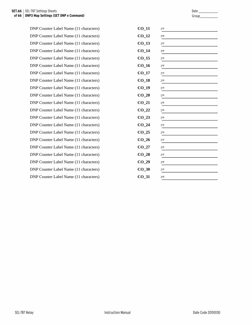
SET.66 of 66
SEL-787 Settings SheetsDNP3 Map Settings (SET DNP n Command)
Date _______________Group______________
SEL-787 Relay Instruction Manual Date Code 20150130
DNP Counter Label Name (11 characters) CO_11 :=
DNP Counter Label Name (11 characters) CO_12 :=
DNP Counter Label Name (11 characters) CO_13 :=
DNP Counter Label Name (11 characters) CO_14 :=
DNP Counter Label Name (11 characters) CO_15 :=
DNP Counter Label Name (11 characters) CO_16 :=
DNP Counter Label Name (11 characters) CO_17 :=
DNP Counter Label Name (11 characters) CO_18 :=
DNP Counter Label Name (11 characters) CO_19 :=
DNP Counter Label Name (11 characters) CO_20 :=
DNP Counter Label Name (11 characters) CO_21 :=
DNP Counter Label Name (11 characters) CO_22 :=
DNP Counter Label Name (11 characters) CO_23 :=
DNP Counter Label Name (11 characters) CO_24 :=
DNP Counter Label Name (11 characters) CO_25 :=
DNP Counter Label Name (11 characters) CO_26 :=
DNP Counter Label Name (11 characters) CO_27 :=
DNP Counter Label Name (11 characters) CO_28 :=
DNP Counter Label Name (11 characters) CO_29 :=
DNP Counter Label Name (11 characters) CO_30 :=
DNP Counter Label Name (11 characters) CO_31 :=
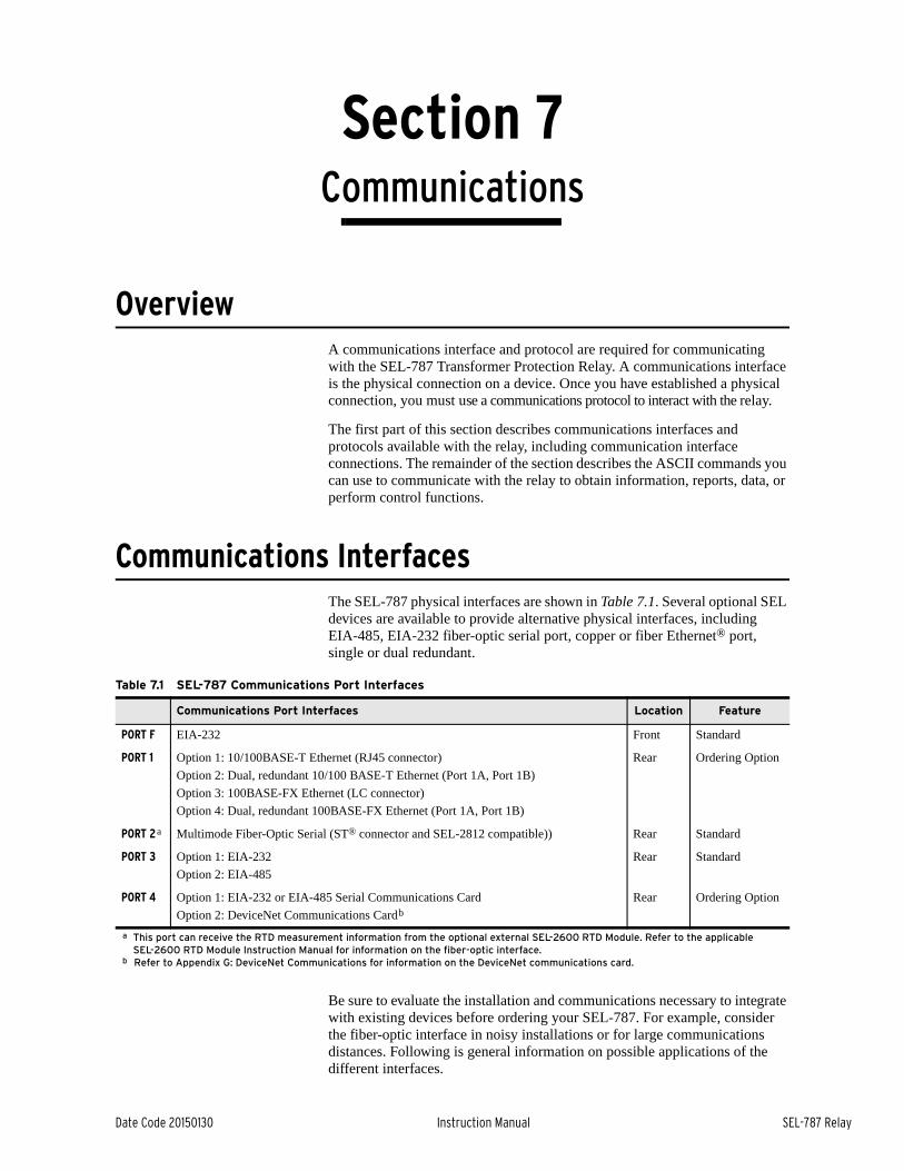
Date Code 20150130 Instruction Manual SEL-787 Relay
Section 7Communications
Instruction Manual
OverviewA communications interface and protocol are required for communicating with the SEL-787 Transformer Protection Relay. A communications interface is the physical connection on a device. Once you have established a physical connection, you must use a communications protocol to interact with the relay.
The first part of this section describes communications interfaces and protocols available with the relay, including communication interface connections. The remainder of the section describes the ASCII commands you can use to communicate with the relay to obtain information, reports, data, or perform control functions.
Communications InterfacesThe SEL-787 physical interfaces are shown in Table 7.1. Several optional SEL devices are available to provide alternative physical interfaces, including EIA-485, EIA-232 fiber-optic serial port, copper or fiber Ethernet® port, single or dual redundant.
Be sure to evaluate the installation and communications necessary to integrate with existing devices before ordering your SEL-787. For example, consider the fiber-optic interface in noisy installations or for large communications distances. Following is general information on possible applications of the different interfaces.
Table 7.1 SEL-787 Communications Port Interfaces
Communications Port Interfaces Location Feature
PORT F EIA-232 Front Standard
PORT 1 Option 1: 10/100BASE-T Ethernet (RJ45 connector)
Option 2: Dual, redundant 10/100 BASE-T Ethernet (Port 1A, Port 1B)
Option 3: 100BASE-FX Ethernet (LC connector)
Option 4: Dual, redundant 100BASE-FX Ethernet (Port 1A, Port 1B)
Rear Ordering Option
PORT 2a Multimode Fiber-Optic Serial (ST® connector and SEL-2812 compatible)) Rear Standard
PORT 3 Option 1: EIA-232
Option 2: EIA-485
Rear Standard
PORT 4 Option 1: EIA-232 or EIA-485 Serial Communications Card
Option 2: DeviceNet Communications Cardb
Rear Ordering Option
a This port can receive the RTD measurement information from the optional external SEL-2600 RTD Module. Refer to the applicable SEL-2600 RTD Module Instruction Manual for information on the fiber-optic interface.
b Refer to Appendix G: DeviceNet Communications for information on the DeviceNet communications card.
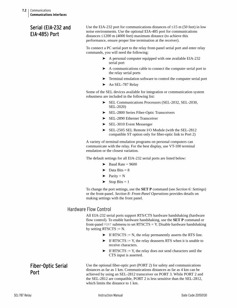
7.2
SEL-787 Relay Instruction Manual Date Code 20150130
CommunicationsCommunications Interfaces
Serial (EIA-232 and EIA-485) Port
Use the EIA-232 port for communications distances of 15 m (50 feet) in low noise environments. Use the optional EIA-485 port for communications distances 1200 m (4000 feet) maximum distance (to achieve this performance, ensure proper line termination at the receiver).
To connect a PC serial port to the relay front-panel serial port and enter relay commands, you will need the following:
➤ A personal computer equipped with one available EIA-232 serial port
➤ A communications cable to connect the computer serial port to the relay serial ports
➤ Terminal emulation software to control the computer serial port
➤ An SEL-787 Relay
Some of the SEL devices available for integration or communication system robustness are included in the following list:
➤ SEL Communications Processors (SEL-2032, SEL-2030, SEL-2020)
➤ SEL-2800 Series Fiber-Optic Transceivers
➤ SEL-2890 Ethernet Transceiver
➤ SEL-3010 Event Messenger
➤ SEL-2505 SEL Remote I/O Module (with the SEL-2812 compatible ST option only for fiber-optic link to Port 2)
A variety of terminal emulation programs on personal computers can communicate with the relay. For the best display, use VT-100 terminal emulation or the closest variation.
The default settings for all EIA-232 serial ports are listed below:
➤ Baud Rate = 9600
➤ Data Bits = 8
➤ Parity = N
➤ Stop Bits = 1
To change the port settings, use the SET P command (see Section 6: Settings) or the front-panel. Section 8: Front-Panel Operations provides details on making settings with the front panel.
Hardware Flow ControlAll EIA-232 serial ports support RTS/CTS hardware handshaking (hardware flow control). To enable hardware handshaking, use the SET P command or front-panel PORT submenu to set RTSCTS = Y. Disable hardware handshaking by setting RTSCTS := N.
➤ If RTSCTS := N, the relay permanently asserts the RTS line.
➤ If RTSCTS := Y, the relay deasserts RTS when it is unable to receive characters.
➤ If RTSCTS := Y, the relay does not send characters until the CTS input is asserted.
Fiber-Optic Serial Port
Use the optional fiber-optic port (PORT 2) for safety and communications distances as far as 1 km. Communications distances as far as 4 km can be achieved by using an SEL-2812 transceiver on PORT 3. While PORT 2 and the SEL-2812 are compatible, PORT 2 is less sensitive than the SEL-2812, which limits the distance to 1 km.
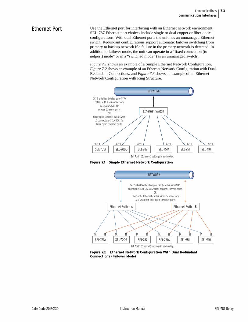
7.3
Date Code 20150130 Instruction Manual SEL-787 Relay
CommunicationsCommunications Interfaces
Ethernet Port Use the Ethernet port for interfacing with an Ethernet network environment. SEL-787 Ethernet port choices include single or dual copper or fiber-optic configurations. With dual Ethernet ports the unit has an unmanaged Ethernet switch. Redundant configurations support automatic failover switching from primary to backup network if a failure in the primary network is detected. In addition to failover mode, the unit can operate in a “fixed connection (to netport) mode” or in a “switched mode” (as an unmanaged switch).
Figure 7.1 shows an example of a Simple Ethernet Network Configuration, Figure 7.2 shows an example of an Ethernet Network Configuration with Dual Redundant Connections, and Figure 7.3 shows an example of an Ethernet Network Configuration with Ring Structure.
Figure 7.1 Simple Ethernet Network Configuration
Figure 7.2 Ethernet Network Configuration With Dual Redundant Connections (Failover Mode)
CAT 5 shielded twisted pair (STP) cables with RJ45 connectors
(SEL-C627/C628) for copper Ethernet ports
ORFiber-optic Ethernet cables with
LC connectors (SEL-C808) for fiber-optic Ethernet ports
Set Port 1 (Ethernet) settings in each relay.
NETWORK
NETWORK
Set Port 1 (Ethernet) settings in each relay.
CAT 5 shielded twisted pair (STP) cables with RJ45 connectors (SEL-C627/C628) for copper Ethernet ports
ORFiber-optic Ethernet cables with LC connectors
(SEL-C808) for fiber-optic Ethernet ports
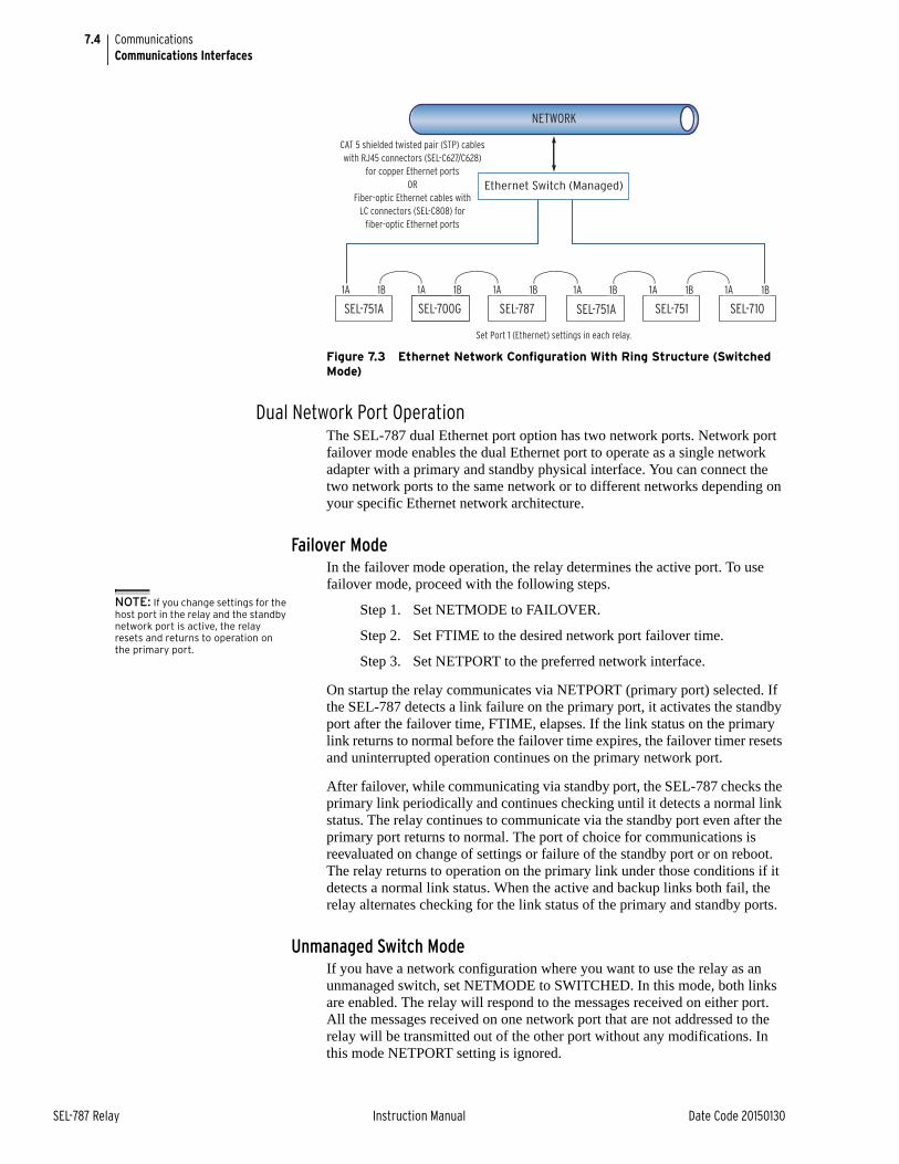
7.4
SEL-787 Relay Instruction Manual Date Code 20150130
CommunicationsCommunications Interfaces
Figure 7.3 Ethernet Network Configuration With Ring Structure (Switched Mode)
Dual Network Port OperationThe SEL-787 dual Ethernet port option has two network ports. Network port failover mode enables the dual Ethernet port to operate as a single network adapter with a primary and standby physical interface. You can connect the two network ports to the same network or to different networks depending on your specific Ethernet network architecture.
Failover ModeIn the failover mode operation, the relay determines the active port. To use failover mode, proceed with the following steps.
Step 1. Set NETMODE to FAILOVER.
Step 2. Set FTIME to the desired network port failover time.
Step 3. Set NETPORT to the preferred network interface.
On startup the relay communicates via NETPORT (primary port) selected. If the SEL-787 detects a link failure on the primary port, it activates the standby port after the failover time, FTIME, elapses. If the link status on the primary link returns to normal before the failover time expires, the failover timer resets and uninterrupted operation continues on the primary network port.
After failover, while communicating via standby port, the SEL-787 checks the primary link periodically and continues checking until it detects a normal link status. The relay continues to communicate via the standby port even after the primary port returns to normal. The port of choice for communications is reevaluated on change of settings or failure of the standby port or on reboot. The relay returns to operation on the primary link under those conditions if it detects a normal link status. When the active and backup links both fail, the relay alternates checking for the link status of the primary and standby ports.
Unmanaged Switch ModeIf you have a network configuration where you want to use the relay as an unmanaged switch, set NETMODE to SWITCHED. In this mode, both links are enabled. The relay will respond to the messages received on either port. All the messages received on one network port that are not addressed to the relay will be transmitted out of the other port without any modifications. In this mode NETPORT setting is ignored.
Set Port 1 (Ethernet) settings in each relay.
NETWORK
CAT 5 shielded twisted pair (STP) cables with RJ45 connectors (SEL-C627/C628)
for copper Ethernet portsOR
Fiber-optic Ethernet cables with LC connectors (SEL-C808) for
fiber-optic Ethernet ports
NOTE: If you change settings for the host port in the relay and the standby network port is active, the relay resets and returns to operation on the primary port.
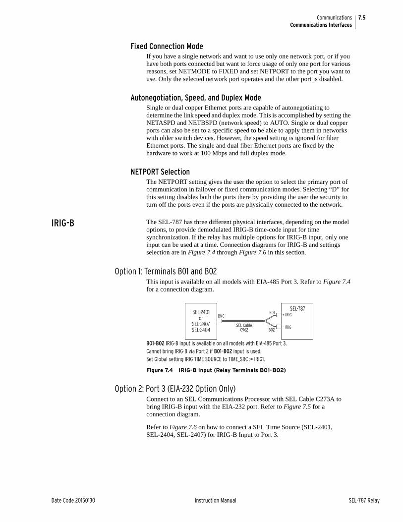
7.5
Date Code 20150130 Instruction Manual SEL-787 Relay
CommunicationsCommunications Interfaces
Fixed Connection ModeIf you have a single network and want to use only one network port, or if you have both ports connected but want to force usage of only one port for various reasons, set NETMODE to FIXED and set NETPORT to the port you want to use. Only the selected network port operates and the other port is disabled.
Autonegotiation, Speed, and Duplex Mode Single or dual copper Ethernet ports are capable of autonegotiating to determine the link speed and duplex mode. This is accomplished by setting the NETASPD and NETBSPD (network speed) to AUTO. Single or dual copper ports can also be set to a specific speed to be able to apply them in networks with older switch devices. However, the speed setting is ignored for fiber Ethernet ports. The single and dual fiber Ethernet ports are fixed by the hardware to work at 100 Mbps and full duplex mode.
NETPORT SelectionThe NETPORT setting gives the user the option to select the primary port of communication in failover or fixed communication modes. Selecting “D” for this setting disables both the ports there by providing the user the security to turn off the ports even if the ports are physically connected to the network.
IRIG-B The SEL-787 has three different physical interfaces, depending on the model options, to provide demodulated IRIG-B time-code input for time synchronization. If the relay has multiple options for IRIG-B input, only one input can be used at a time. Connection diagrams for IRIG-B and settings selection are in Figure 7.4 through Figure 7.6 in this section.
Option 1: Terminals B01 and B02This input is available on all models with EIA-485 Port 3. Refer to Figure 7.4 for a connection diagram.
B01–B02 IRIG-B input is available on all models with EIA-485 Port 3.Cannot bring IRIG-B via Port 2 if B01–B02 input is used.Set Global setting IRIG TIME SOURCE to TIME_SRC := IRIG1.
Figure 7.4 IRIG-B Input (Relay Terminals B01–B02)
Option 2: Port 3 (EIA-232 Option Only)Connect to an SEL Communications Processor with SEL Cable C273A to bring IRIG-B input with the EIA-232 port. Refer to Figure 7.5 for a connection diagram.
Refer to Figure 7.6 on how to connect a SEL Time Source (SEL-2401, SEL-2404, SEL-2407) for IRIG-B Input to Port 3.
SEL-2401or
SEL-2407SEL-2404
SEL-787+ IRIG
– IRIGSEL CableC962
B01
B02
BNC
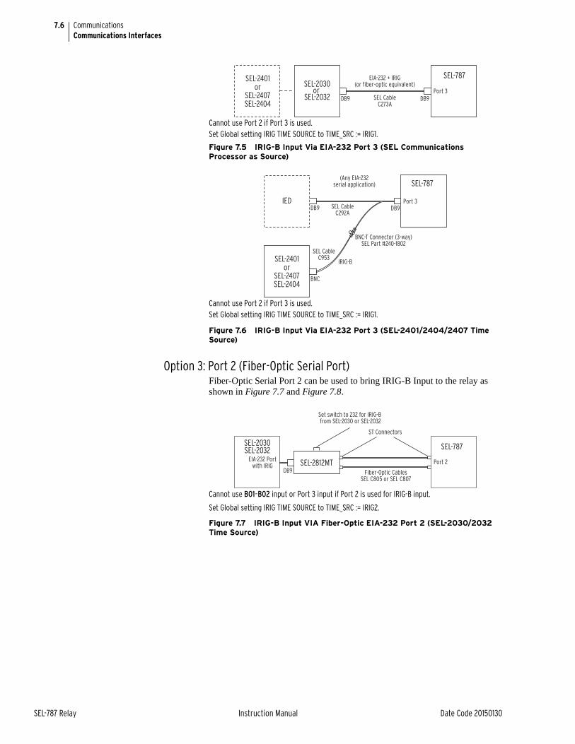
7.6
SEL-787 Relay Instruction Manual Date Code 20150130
CommunicationsCommunications Interfaces
Cannot use Port 2 if Port 3 is used.Set Global setting IRIG TIME SOURCE to TIME_SRC := IRIG1.
Figure 7.5 IRIG-B Input Via EIA-232 Port 3 (SEL Communications Processor as Source)
Cannot use Port 2 if Port 3 is used.Set Global setting IRIG TIME SOURCE to TIME_SRC := IRIG1.
Figure 7.6 IRIG-B Input Via EIA-232 Port 3 (SEL-2401/2404/2407 Time Source)
Option 3: Port 2 (Fiber-Optic Serial Port)Fiber-Optic Serial Port 2 can be used to bring IRIG-B Input to the relay as shown in Figure 7.7 and Figure 7.8.
Cannot use B01–B02 input or Port 3 input if Port 2 is used for IRIG-B input.
Set Global setting IRIG TIME SOURCE to TIME_SRC := IRIG2.
Figure 7.7 IRIG-B Input VIA Fiber-Optic EIA-232 Port 2 (SEL-2030/2032 Time Source)
SEL-2401or
SEL-2407SEL-2404
SEL-2030or
SEL-2032 DB9Port 3
EIA-232 + IRIG(or fiber-optic equivalent)
SEL CableC273A
SEL-787
DB9
SEL-2401or
SEL-2407SEL-2404
SEL-787
DB9
BNC
IED
(Any EIA-232serial application)
SEL CableC292A
SEL CableC953
BNC-T Connector (3-way)SEL Part #240-1802
DB9
IRIG-B
Port 3
SEL-2812MT
SEL-2030SEL-2032
EIA-232 Portwith IRIG
DB9 Fiber-Optic CablesSEL C805 or SEL C807
Port 2
Set switch to 232 for IRIG-B from SEL-2030 or SEL-2032
ST Connectors
SEL-787
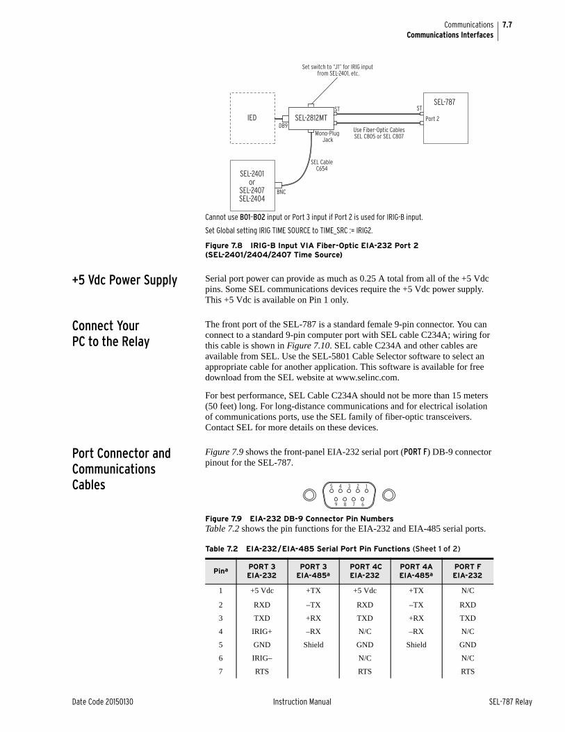
7.7
Date Code 20150130 Instruction Manual SEL-787 Relay
CommunicationsCommunications Interfaces
Cannot use B01–B02 input or Port 3 input if Port 2 is used for IRIG-B input.
Set Global setting IRIG TIME SOURCE to TIME_SRC := IRIG2.
Figure 7.8 IRIG-B Input VIA Fiber-Optic EIA-232 Port 2 (SEL-2401/2404/2407 Time Source)
+5 Vdc Power Supply Serial port power can provide as much as 0.25 A total from all of the +5 Vdc pins. Some SEL communications devices require the +5 Vdc power supply. This +5 Vdc is available on Pin 1 only.
Connect Your PC to the Relay
The front port of the SEL-787 is a standard female 9-pin connector. You can connect to a standard 9-pin computer port with SEL cable C234A; wiring for this cable is shown in Figure 7.10. SEL cable C234A and other cables are available from SEL. Use the SEL-5801 Cable Selector software to select an appropriate cable for another application. This software is available for free download from the SEL website at www.selinc.com.
For best performance, SEL Cable C234A should not be more than 15 meters (50 feet) long. For long-distance communications and for electrical isolation of communications ports, use the SEL family of fiber-optic transceivers. Contact SEL for more details on these devices.
Port Connector and Communications Cables
Figure 7.9 shows the front-panel EIA-232 serial port (PORT F) DB-9 connector pinout for the SEL-787.
Figure 7.9 EIA-232 DB-9 Connector Pin NumbersTable 7.2 shows the pin functions for the EIA-232 and EIA-485 serial ports.
SEL-2812MT
SEL-2401or
SEL-2407SEL-2404
IEDDB9
Mono-Plug Jack
Use Fiber-Optic CablesSEL C805 or SEL C807
SEL CableC654
Port 2
Set switch to “J1” for IRIG input from SEL-2401, etc.
STST
BNC
SEL-787
Table 7.2 EIA-232/EIA-485 Serial Port Pin Functions (Sheet 1 of 2)
Pina PORT 3 EIA-232
PORT 3 EIA-485a
PORT 4C EIA-232
PORT 4A EIA-485a
PORT F EIA-232
1 +5 Vdc +TX +5 Vdc +TX N/C
2 RXD –TX RXD –TX RXD
3 TXD +RX TXD +RX TXD
4 IRIG+ –RX N/C –RX N/C
5 GND Shield GND Shield GND
6 IRIG– N/C N/C
7 RTS RTS RTS
5 4 3 2 1
9 8 7 6
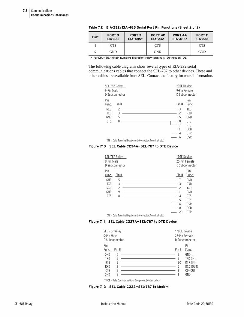
7.8
SEL-787 Relay Instruction Manual Date Code 20150130
CommunicationsCommunications Interfaces
The following cable diagrams show several types of EIA-232 serial communications cables that connect the SEL-787 to other devices. These and other cables are available from SEL. Contact the factory for more information.
Figure 7.10 SEL Cable C234A—SEL-787 to DTE Device
Figure 7.11 SEL Cable C227A—SEL-787 to DTE Device
Figure 7.12 SEL Cable C222—SEL-787 to Modem
8 CTS CTS CTS
9 GND GND GND
a For EIA-485, the pin numbers represent relay terminals _O1 through _05.
Table 7.2 EIA-232/EIA-485 Serial Port Pin Functions (Sheet 2 of 2)
Pina PORT 3 EIA-232
PORT 3 EIA-485a
PORT 4C EIA-232
PORT 4A EIA-485a
PORT F EIA-232
SEL-787 Relay9-Pin MaleD Subconnector
9-Pin FemaleD Subconnector
2358
32587146
RXDTXDGNDCTS
TXDRXDGNDCTSRTSDCDDTRDSR
PinFunc.
PinFunc.Pin # Pin #
*DTE Device
*DTE = Data Terminal Equipment (Computer, Terminal, etc.)
SEL-787 Relay9-Pin MaleD Subconnector
25-Pin FemaleD Subconnector
53298
7321456820
GNDTXDRXDGNDCTS
GNDRXDTXDGNDRTSCTSDSRDCDDTR
PinFunc.
PinFunc.Pin # Pin #
*DTE Device
*DTE = Data Terminal Equipment (Computer, Terminal, etc.)
SEL-787 Relay9-Pin MaleD Subconnector
25-Pin FemaleD Subconnector
537289
7220381
GNDTXDRTSRXDCTSGND
GNDTXD (IN)DTR (IN)RXD (OUT)CD (OUT)GND
PinFunc.
PinFunc.Pin # Pin #
**DCE Device
**DCE = Data Communications Equipment (Modem, etc.)
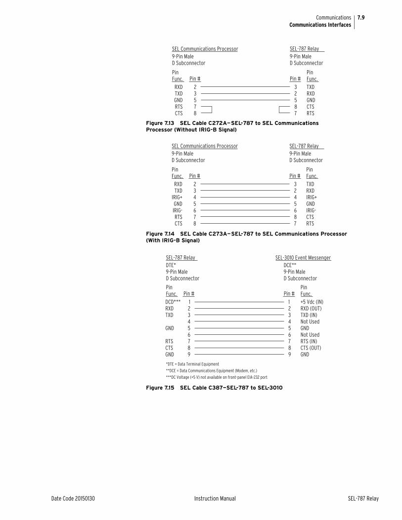
7.9
Date Code 20150130 Instruction Manual SEL-787 Relay
CommunicationsCommunications Interfaces
Figure 7.13 SEL Cable C272A—SEL-787 to SEL Communications Processor (Without IRIG-B Signal)
Figure 7.14 SEL Cable C273A—SEL-787 to SEL Communications Processor (With IRIG-B Signal)
Figure 7.15 SEL Cable C387—SEL-787 to SEL-3010
SEL Communications Processor9-Pin MaleD Subconnector
9-Pin MaleD Subconnector
23578
32587
RXDTXDGNDRTSCTS
TXDRXDGNDCTSRTS
PinFunc.
PinFunc.Pin # Pin #
SEL-787 Relay
SEL Communications Processor9-Pin MaleD Subconnector
9-Pin MaleD Subconnector
2345678
3245687
RXDTXD
IRIG+GNDIRIG-RTSCTS
TXDRXDIRIG+GNDIRIG-CTSRTS
PinFunc.
PinFunc.Pin # Pin #
SEL-787 Relay
SEL-787 RelayDTE*9-Pin MaleD Subconnector
DCE**9-Pin MaleD Subconnector
123456789
123456789
DCD***RXDTXD
GND
RTSCTSGND
+5 Vdc (IN)RXD (OUT)TXD (IN)Not UsedGNDNot UsedRTS (IN)CTS (OUT)GND
PinFunc.
PinFunc.Pin # Pin #
SEL-3010 Event Messenger
*DTE = Data Terminal Equipment
**DCE = Data Communications Equipment (Modem, etc.)
***DC Voltage (+5 V) not available on front-panel EIA-232 port
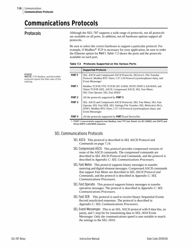
7.10
SEL-787 Relay Instruction Manual Date Code 20150130
CommunicationsCommunications Protocols
Communications ProtocolsProtocols Although the SEL-787 supports a wide range of protocols, not all protocols
are available on all ports. In addition, not all hardware options support all protocols.
Be sure to select the correct hardware to support a particular protocol. For example, if Modbus® TCP is necessary for your application, be sure to order the Ethernet option for Port 1. Table 7.3 shows the ports and the protocols available on each port.
SEL Communications ProtocolsSEL ASCII. This protocol is described in SEL ASCII Protocol and
Commands on page 7.14.
SEL Compressed ASCII. This protocol provides compressed versions of some of the ASCII commands. The compressed commands are described in SEL ASCII Protocol and Commands, and the protocol is described in Appendix C: SEL Communications Processors.
SEL Fast Meter. This protocol supports binary messages to transfer metering and digital element messages. Compressed ASCII commands that support Fast Meter are described in SEL ASCII Protocol and Commands, and the protocol is described in Appendix C: SEL Communications Processors.
SEL Fast Operate. This protocol supports binary messages to transfer operation messages. The protocol is described in Appendix C: SEL Communications Processors.
SEL Fast SER. This protocol is used to receive binary Sequential Events Record unsolicited responses. The protocol is described in Appendix C: SEL Communications Processors.
SEL Event Messenger. This is an SEL ASCII protocol with 8 data bits, no parity, and 1 stop bit for transmitting data to SEL-3010 Event Messenger. Only the communications speed is user settable to match the settings in the SEL-3010.
Table 7.3 Protocols Supported on the Various Ports
Supported Protocol
PORT F SEL ASCII and Compressed ASCII Protocols, SELBOOT, File Transfer Protocol, Modbus RTU Slave, C37.118 Protocol (synchrophasor data), and Event Messenger
PORT 1 Modbus TCP/IP, FTP, TCP/IP, IEC 61850, SNTP. DNP3 LAN/WAN, and Telnet TCP/IP (SEL ASCII, Compressed ASCII, SEL Fast Meter, SEL Fast Operate, SEL Fast SER)a
a PORT 1 concurrently supports two Modbus, two FTP, two Telnet, six IEC 61850, one SNTP, and three DNP3 LAN/WAN sessions.
PORT 2 All the protocols supported by PORT 3
PORT 3 SEL ASCII and Compressed ASCII Protocols, SEL Fast Meter, SEL Fast Operate, SEL Fast SER, SEL Settings File Transfer, SEL MIRRORED BITS, DNP3, Modbus RTU Slave, C37.118 Protocol (synchrophasor data), and Event Messenger
PORT 4 All the protocols supported by PORT 3 and DeviceNet
NOTE: FTP, Modbus, and DeviceNet protocols ignore the hide rules of the settings.
7.11
Date Code 20150130 Instruction Manual SEL-787 Relay
CommunicationsCommunications Protocols
MIRRORED BITS ProtocolThe SEL-787 supports two MIRRORED BITS communications channels, designated A and B. Within each MIRRORED BITS communications message for a given channel (A or B), there are eight logical data channels (1–8). You can, for example, set MBA on Port 3 of the base unit and MBB on Port 4A of the optional communications card. Attempting to set the PROTO setting to MBA, MB8A, or MBTA when channel A is already assigned to another port (or MBB, MB8B, or MBTB when channel B is already assigned on another port) results in the following error message: This Mirrored Bits channel is assigned to another port. After displaying the error message, the device returns to the PROTO setting for reentry.
C37.118 ProtocolThe SEL-787 provides C37.118 protocol (synchrophasor data) support at one of the serial ports F, 2, 3, or 4. The protocol is described in Appendix H: Synchrophasors.
Modbus RTU ProtocolThe SEL-787 provides Modbus RTU support. Modbus is a protocol described in Appendix E: Modbus RTU Communications.
DNP3 (Distributed Network Protocol)The SEL-787 provides DNP3 protocol support if the option is selected. The DNP3 protocol is described in Appendix D: DNP3 Communications.
DeviceNetThe SEL-787 provides DeviceNet support. DeviceNet is an optional protocol described in Appendix G: DeviceNet Communications.
Ethernet Protocols As with other communications interfaces, you must choose a data exchange protocol that operates over the Ethernet network link in order to exchange data. The relay supports FTP, Telnet, Ping, Modbus/TCP, IEC 61850, and DNP3 LAN/WAN protocols.
You should carefully design your Ethernet network to maximize reliability, minimize system administration effort, and provide adequate security. Work with a networking professional to design your substation Ethernet network.
FTP ServerUse the single FTP (File Transfer Protocol) session to access the following files:
➤ CFG.XML—Configuration read-only file in XML format
➤ CFG.TXT—Configuration read-only file in TXT format
➤ ERR.TXT—Error read-only file in TXT format
➤ SET_61850.CID—IEC 61850 CID read-write file
➤ SET_xx.TXT—Setting files in TXT format
FTP is a standard TCP/IP protocol for exchanging files. A free FTP application is included with most web browser software. You can also obtain a free or inexpensive FTP application from the Internet. When you connect to the relay Ethernet port, you will find files stored in the root (top-level) directory.
7.12
SEL-787 Relay Instruction Manual Date Code 20150130
CommunicationsCommunications Protocols
Telnet ServerUse the Telnet session (TPORT default setting is port 23) to connect to the relay to use the protocols, which are described in more detail below:
➤ SEL ASCII
➤ Compressed ASCII
➤ Fast Meter
➤ Fast Operate
Telnet is a terminal connection across a TCP/IP network that operates in a manner very similar to a direct serial port connection to one of the relay ports. As with FTP, Telnet is a part of TCP/IP. A free Telnet application is included with most computer operating systems, or you can obtain low-cost or free Telnet applications on the Internet.
Ping ServerUse a Ping client with the relay Ping server to verify that your network configuration is correct. Ping is an application based on ICMP over an IP network. A free Ping application is included with most computer operating systems.
IEC 61850Use as many as six sessions of MMS over a TCP network to exchange data with the relay. Use GOOSE to do real-time data exchange with as many as 16 incoming messages and 8 outgoing messages. For more details on the IEC 61850 protocol, see Appendix F: IEC 61850 Communications.
Simple Network Time Protocol (SNTP)
When Port 1 (Ethernet port) setting ESNTP is not OFF, the internal clock of the relay conditionally synchronizes to the time of day served by a Network Time Protocol (NTP) server. The relay uses a simplified version of NTP called the Simple Network Time Protocol (SNTP). SNTP is not as accurate as IRIG-B. The relay can use SNTP as a less accurate primary time source, or as a backup to the higher accuracy IRIG-B time source.
SNTP as Primary or Backup Time SourceIf an IRIG-B time source is connected and either Relay Word bit TSOK or Relay Word bit IRIGOK asserts, then the relay synchronizes the internal time-of-day clock to the incoming IRIB-G time code signal, even if SNTP is configured in the relay and an NTP server is available. If the IRIG-B source is disconnected (if both TSOK and IRIGOK deassert) then the relay synchronizes the internal time-of-day clock to the NTP server, if available. In this way, an NTP server acts either as the primary time source or as a backup time source to the more accurate IRIG-B time source.
Creating an NTP ServerThree SEL application notes, available from the SEL website, describe how to create an NTP server.
➤ AN2009-10: Using an SEL-2401, SEL-2404, or SEL-2407 to Serve NTP Via the SEL-3530 RTAC
➤ AN2009-32: Using SEL Satellite-Synchronized Clocks With the SEL-3332 or SEL-3351 to Output NTP
➤ Using an SEL-2401, SEL-2404, or SEL-2407 to Create a Stratum 1 Linux NTP Server
NOTE: Use the QUIT command prior to closing the Telnet-to-Host session to set the relay to Access Level 0. Otherwise the relay will remain at an elevated access level until TIDLE expires.
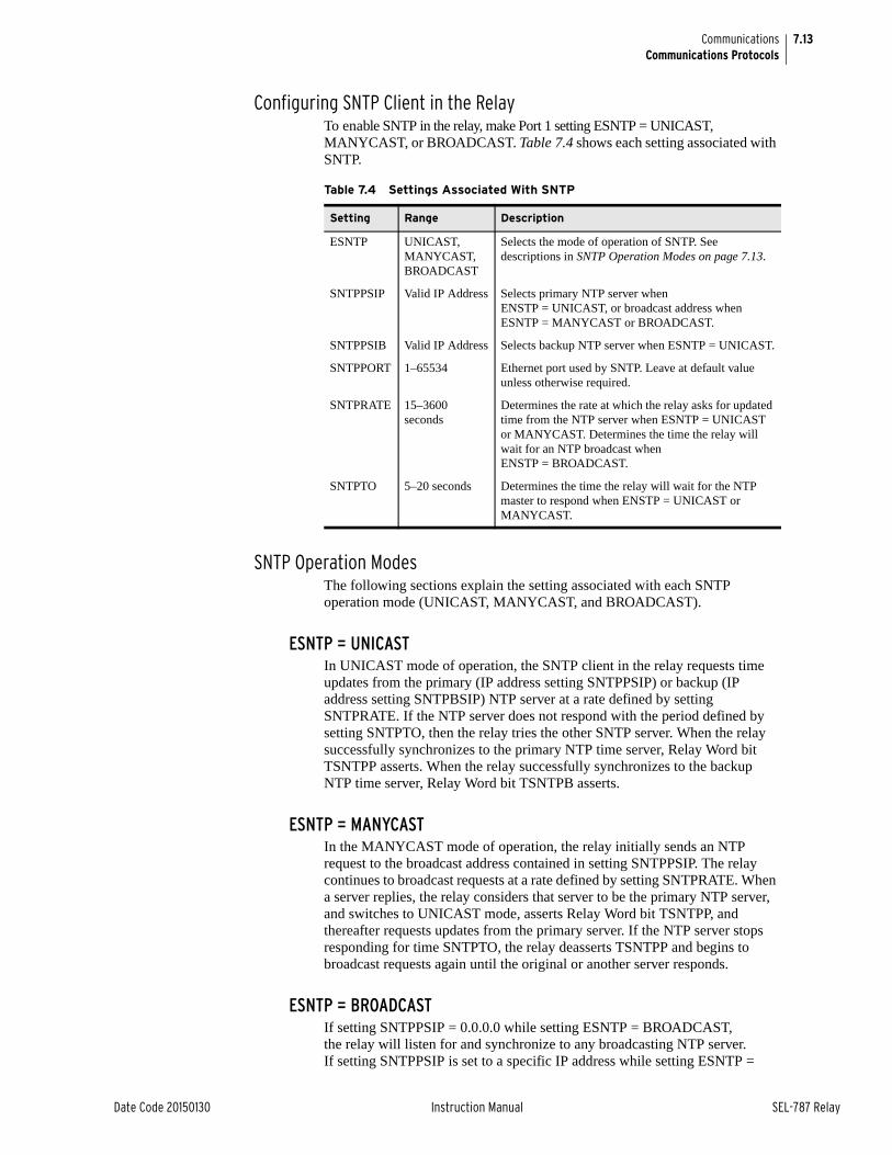
7.13
Date Code 20150130 Instruction Manual SEL-787 Relay
CommunicationsCommunications Protocols
Configuring SNTP Client in the RelayTo enable SNTP in the relay, make Port 1 setting ESNTP = UNICAST, MANYCAST, or BROADCAST. Table 7.4 shows each setting associated with SNTP.
SNTP Operation ModesThe following sections explain the setting associated with each SNTP operation mode (UNICAST, MANYCAST, and BROADCAST).
ESNTP = UNICASTIn UNICAST mode of operation, the SNTP client in the relay requests time updates from the primary (IP address setting SNTPPSIP) or backup (IP address setting SNTPBSIP) NTP server at a rate defined by setting SNTPRATE. If the NTP server does not respond with the period defined by setting SNTPTO, then the relay tries the other SNTP server. When the relay successfully synchronizes to the primary NTP time server, Relay Word bit TSNTPP asserts. When the relay successfully synchronizes to the backup NTP time server, Relay Word bit TSNTPB asserts.
ESNTP = MANYCASTIn the MANYCAST mode of operation, the relay initially sends an NTP request to the broadcast address contained in setting SNTPPSIP. The relay continues to broadcast requests at a rate defined by setting SNTPRATE. When a server replies, the relay considers that server to be the primary NTP server, and switches to UNICAST mode, asserts Relay Word bit TSNTPP, and thereafter requests updates from the primary server. If the NTP server stops responding for time SNTPTO, the relay deasserts TSNTPP and begins to broadcast requests again until the original or another server responds.
ESNTP = BROADCASTIf setting SNTPPSIP = 0.0.0.0 while setting ESNTP = BROADCAST, the relay will listen for and synchronize to any broadcasting NTP server. If setting SNTPPSIP is set to a specific IP address while setting ESNTP =
Table 7.4 Settings Associated With SNTP
Setting Range Description
ESNTP UNICAST, MANYCAST, BROADCAST
Selects the mode of operation of SNTP. See descriptions in SNTP Operation Modes on page 7.13.
SNTPPSIP Valid IP Address Selects primary NTP server when ENSTP = UNICAST, or broadcast address when ESNTP = MANYCAST or BROADCAST.
SNTPPSIB Valid IP Address Selects backup NTP server when ESNTP = UNICAST.
SNTPPORT 1–65534 Ethernet port used by SNTP. Leave at default value unless otherwise required.
SNTPRATE 15–3600 seconds
Determines the rate at which the relay asks for updated time from the NTP server when ESNTP = UNICAST or MANYCAST. Determines the time the relay will wait for an NTP broadcast when ENSTP = BROADCAST.
SNTPTO 5–20 seconds Determines the time the relay will wait for the NTP master to respond when ENSTP = UNICAST or MANYCAST.
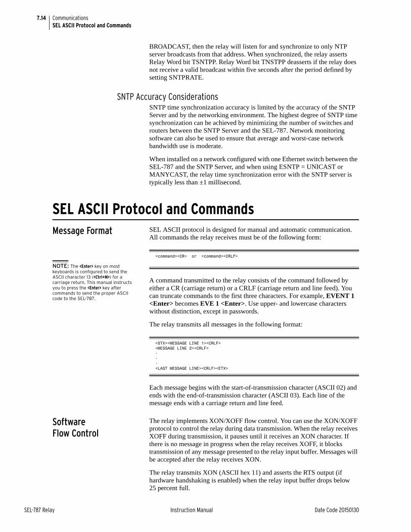
7.14
SEL-787 Relay Instruction Manual Date Code 20150130
CommunicationsSEL ASCII Protocol and Commands
BROADCAST, then the relay will listen for and synchronize to only NTP server broadcasts from that address. When synchronized, the relay asserts Relay Word bit TSNTPP. Relay Word bit TNSTPP deasserts if the relay does not receive a valid broadcast within five seconds after the period defined by setting SNTPRATE.
SNTP Accuracy ConsiderationsSNTP time synchronization accuracy is limited by the accuracy of the SNTP Server and by the networking environment. The highest degree of SNTP time synchronization can be achieved by minimizing the number of switches and routers between the SNTP Server and the SEL-787. Network monitoring software can also be used to ensure that average and worst-case network bandwidth use is moderate.
When installed on a network configured with one Ethernet switch between the SEL-787 and the SNTP Server, and when using ESNTP = UNICAST or MANYCAST, the relay time synchronization error with the SNTP server is typically less than ±1 millisecond.
SEL ASCII Protocol and CommandsMessage Format SEL ASCII protocol is designed for manual and automatic communication.
All commands the relay receives must be of the following form:
A command transmitted to the relay consists of the command followed by either a CR (carriage return) or a CRLF (carriage return and line feed). You can truncate commands to the first three characters. For example, EVENT 1 <Enter> becomes EVE 1 <Enter>. Use upper- and lowercase characters without distinction, except in passwords.
The relay transmits all messages in the following format:
Each message begins with the start-of-transmission character (ASCII 02) and ends with the end-of-transmission character (ASCII 03). Each line of the message ends with a carriage return and line feed.
Software Flow Control
The relay implements XON/XOFF flow control. You can use the XON/XOFF protocol to control the relay during data transmission. When the relay receives XOFF during transmission, it pauses until it receives an XON character. If there is no message in progress when the relay receives XOFF, it blocks transmission of any message presented to the relay input buffer. Messages will be accepted after the relay receives XON.
The relay transmits XON (ASCII hex 11) and asserts the RTS output (if hardware handshaking is enabled) when the relay input buffer drops below 25 percent full.
<command><CR> or <command><CRLF>
<STX><MESSAGE LINE 1><CRLF><MESSAGE LINE 2><CRLF>•••<LAST MESSAGE LINE><CRLF><ETX>
NOTE: The <Enter> key on most keyboards is configured to send the ASCII character 13 (<Ctrl+M>) for a carriage return. This manual instructs you to press the <Enter> key after commands to send the proper ASCII code to the SEL-787.
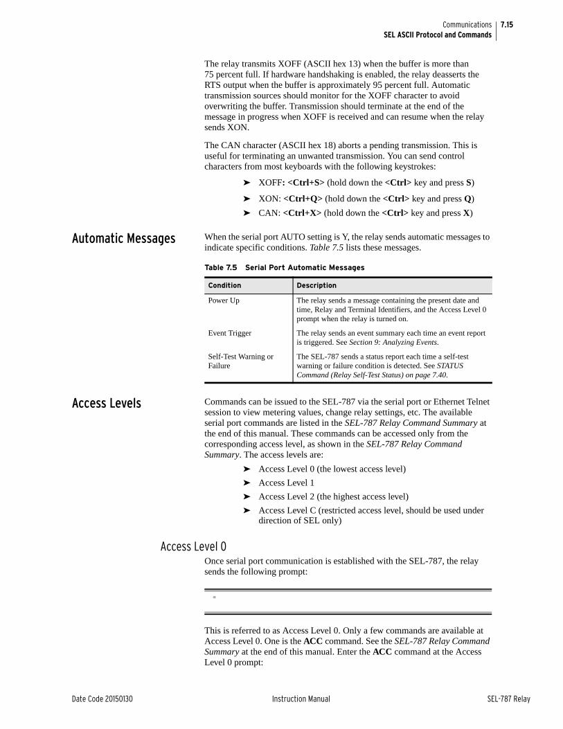
7.15
Date Code 20150130 Instruction Manual SEL-787 Relay
CommunicationsSEL ASCII Protocol and Commands
The relay transmits XOFF (ASCII hex 13) when the buffer is more than 75 percent full. If hardware handshaking is enabled, the relay deasserts the RTS output when the buffer is approximately 95 percent full. Automatic transmission sources should monitor for the XOFF character to avoid overwriting the buffer. Transmission should terminate at the end of the message in progress when XOFF is received and can resume when the relay sends XON.
The CAN character (ASCII hex 18) aborts a pending transmission. This is useful for terminating an unwanted transmission. You can send control characters from most keyboards with the following keystrokes:
➤ XOFF: <Ctrl+S> (hold down the <Ctrl> key and press S)
➤ XON: <Ctrl+Q> (hold down the <Ctrl> key and press Q)
➤ CAN: <Ctrl+X> (hold down the <Ctrl> key and press X)
Automatic Messages When the serial port AUTO setting is Y, the relay sends automatic messages to indicate specific conditions. Table 7.5 lists these messages.
Access Levels Commands can be issued to the SEL-787 via the serial port or Ethernet Telnet session to view metering values, change relay settings, etc. The available serial port commands are listed in the SEL-787 Relay Command Summary at the end of this manual. These commands can be accessed only from the corresponding access level, as shown in the SEL-787 Relay Command Summary. The access levels are:
➤ Access Level 0 (the lowest access level)
➤ Access Level 1
➤ Access Level 2 (the highest access level)
➤ Access Level C (restricted access level, should be used under direction of SEL only)
Access Level 0Once serial port communication is established with the SEL-787, the relay sends the following prompt:
This is referred to as Access Level 0. Only a few commands are available at Access Level 0. One is the ACC command. See the SEL-787 Relay Command Summary at the end of this manual. Enter the ACC command at the Access Level 0 prompt:
Table 7.5 Serial Port Automatic Messages
Condition Description
Power Up The relay sends a message containing the present date and time, Relay and Terminal Identifiers, and the Access Level 0 prompt when the relay is turned on.
Event Trigger The relay sends an event summary each time an event report is triggered. See Section 9: Analyzing Events.
Self-Test Warning or Failure
The SEL-787 sends a status report each time a self-test warning or failure condition is detected. See STATUS Command (Relay Self-Test Status) on page 7.40.
=
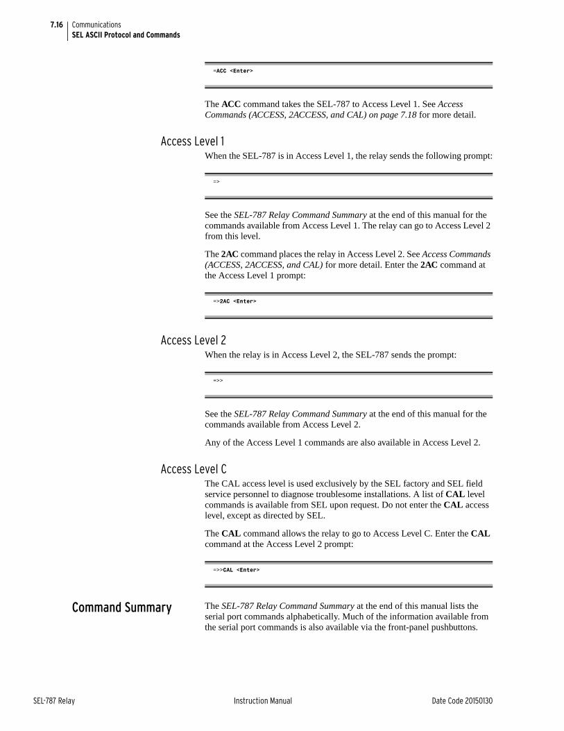
7.16
SEL-787 Relay Instruction Manual Date Code 20150130
CommunicationsSEL ASCII Protocol and Commands
The ACC command takes the SEL-787 to Access Level 1. See Access Commands (ACCESS, 2ACCESS, and CAL) on page 7.18 for more detail.
Access Level 1When the SEL-787 is in Access Level 1, the relay sends the following prompt:
See the SEL-787 Relay Command Summary at the end of this manual for the commands available from Access Level 1. The relay can go to Access Level 2 from this level.
The 2AC command places the relay in Access Level 2. See Access Commands (ACCESS, 2ACCESS, and CAL) for more detail. Enter the 2AC command at the Access Level 1 prompt:
Access Level 2When the relay is in Access Level 2, the SEL-787 sends the prompt:
See the SEL-787 Relay Command Summary at the end of this manual for the commands available from Access Level 2.
Any of the Access Level 1 commands are also available in Access Level 2.
Access Level CThe CAL access level is used exclusively by the SEL factory and SEL field service personnel to diagnose troublesome installations. A list of CAL level commands is available from SEL upon request. Do not enter the CAL access level, except as directed by SEL.
The CAL command allows the relay to go to Access Level C. Enter the CAL command at the Access Level 2 prompt:
Command Summary The SEL-787 Relay Command Summary at the end of this manual lists the serial port commands alphabetically. Much of the information available from the serial port commands is also available via the front-panel pushbuttons.
=ACC <Enter>
=>
=>2AC <Enter>
=>>
=>>CAL <Enter>
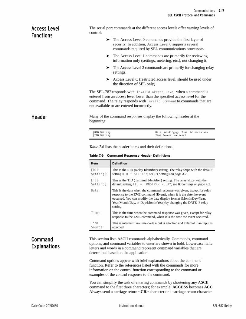
7.17
Date Code 20150130 Instruction Manual SEL-787 Relay
CommunicationsSEL ASCII Protocol and Commands
Access Level Functions
The serial port commands at the different access levels offer varying levels of control:
➤ The Access Level 0 commands provide the first layer of security. In addition, Access Level 0 supports several commands required by SEL communications processors.
➤ The Access Level 1 commands are primarily for reviewing information only (settings, metering, etc.), not changing it.
➤ The Access Level 2 commands are primarily for changing relay settings.
➤ Access Level C (restricted access level, should be used under the direction of SEL only)
The SEL-787 responds with Invalid Access Level when a command is entered from an access level lower than the specified access level for the command. The relay responds with Invalid Command to commands that are not available or are entered incorrectly.
Header Many of the command responses display the following header at the beginning:
Table 7.6 lists the header items and their definitions.
Command Explanations
This section lists ASCII commands alphabetically. Commands, command options, and command variables to enter are shown in bold. Lowercase italic letters and words in a command represent command variables that are determined based on the application.
Command options appear with brief explanations about the command function. Refer to the references listed with the commands for more information on the control function corresponding to the command or examples of the control response to the command.
You can simplify the task of entering commands by shortening any ASCII command to the first three characters; for example, ACCESS becomes ACC. Always send a carriage return <CR> character or a carriage return character
[RID Setting] Date: mm/dd/yyyy Time: hh:mm:ss.sss[TID Setting] Time Source: external
Table 7.6 Command Response Header Definitions
Item Definition
[RID Setting]:
This is the RID (Relay Identifier) setting. The relay ships with the default setting RID = SEL-787; see ID Settings on page 4.2.
[TID Setting]:
This is the TID (Terminal Identifier) setting. The relay ships with the default setting TID = TRNSFRMR RELAY; see ID Settings on page 4.2.
Date: This is the date when the command response was given, except for relay response to the EVE command (Event), when it is the date the event occurred. You can modify the date display format (Month/Day/Year, Year/Month/Day, or Day/Month/Year) by changing the DATE_F relay setting.
Time: This is the time when the command response was given, except for relay response to the EVE command, when it is the time the event occurred.
Time Source:
This is internal if no time-code input is attached and external if an input is attached.
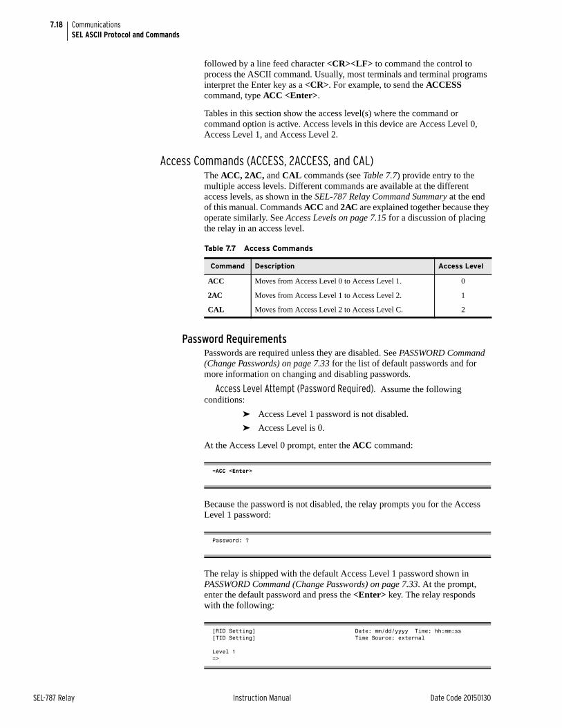
7.18
SEL-787 Relay Instruction Manual Date Code 20150130
CommunicationsSEL ASCII Protocol and Commands
followed by a line feed character <CR><LF> to command the control to process the ASCII command. Usually, most terminals and terminal programs interpret the Enter key as a <CR>. For example, to send the ACCESS command, type ACC <Enter>.
Tables in this section show the access level(s) where the command or command option is active. Access levels in this device are Access Level 0, Access Level 1, and Access Level 2.
Access Commands (ACCESS, 2ACCESS, and CAL)The ACC, 2AC, and CAL commands (see Table 7.7) provide entry to the multiple access levels. Different commands are available at the different access levels, as shown in the SEL-787 Relay Command Summary at the end of this manual. Commands ACC and 2AC are explained together because they operate similarly. See Access Levels on page 7.15 for a discussion of placing the relay in an access level.
Password RequirementsPasswords are required unless they are disabled. See PASSWORD Command (Change Passwords) on page 7.33 for the list of default passwords and for more information on changing and disabling passwords.
Access Level Attempt (Password Required). Assume the following conditions:
➤ Access Level 1 password is not disabled.
➤ Access Level is 0.
At the Access Level 0 prompt, enter the ACC command:
Because the password is not disabled, the relay prompts you for the Access Level 1 password:
The relay is shipped with the default Access Level 1 password shown in PASSWORD Command (Change Passwords) on page 7.33. At the prompt, enter the default password and press the <Enter> key. The relay responds with the following:
Table 7.7 Access Commands
Command Description Access Level
ACC Moves from Access Level 0 to Access Level 1. 0
2AC Moves from Access Level 1 to Access Level 2. 1
CAL Moves from Access Level 2 to Access Level C. 2
=ACC <Enter>
Password: ?
[RID Setting] Date: mm/dd/yyyy Time: hh:mm:ss[TID Setting] Time Source: external
Level 1=>
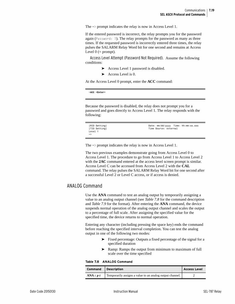
7.19
Date Code 20150130 Instruction Manual SEL-787 Relay
CommunicationsSEL ASCII Protocol and Commands
The => prompt indicates the relay is now in Access Level 1.
If the entered password is incorrect, the relay prompts you for the password again (Password: ?). The relay prompts for the password as many as three times. If the requested password is incorrectly entered three times, the relay pulses the SALARM Relay Word bit for one second and remains at Access Level 0 (= prompt).
Access Level Attempt (Password Not Required). Assume the following conditions:
➤ Access Level 1 password is disabled.
➤ Access Level is 0.
At the Access Level 0 prompt, enter the ACC command:
Because the password is disabled, the relay does not prompt you for a password and goes directly to Access Level 1. The relay responds with the following:
The => prompt indicates the relay is now in Access Level 1.
The two previous examples demonstrate going from Access Level 0 to Access Level 1. The procedure to go from Access Level 1 to Access Level 2 with the 2AC command entered at the access level screen prompt is similar. Access Level C can be accessed from Access Level 2 with the CAL command. The relay pulses the SALARM Relay Word bit for one second after a successful Level 2 or Level C access, or if access is denied.
ANALOG Command
Use the ANA command to test an analog output by temporarily assigning a value to an analog output channel (see Table 7.8 for the command description and Table 7.9 for the format). After entering the ANA command, the device suspends normal operation of the analog output channel and scales the output to a percentage of full scale. After assigning the specified value for the specified time, the device returns to normal operation.
Entering any character (including pressing the space key) ends the command before reaching the specified interval completion. You can test the analog output in one of the following two modes:
➤ Fixed percentage: Outputs a fixed percentage of the signal for a specified duration
➤ Ramp: Ramps the output from minimum to maximum of full scale over the time specified
=ACC <Enter>
[RID Setting] Date: mm/dd/yyyy Time: hh:mm:ss.sss[TID Setting] Time Source: externalLevel 1=>
Table 7.8 ANALOG Command
Command Description Access Level
ANA c p t Temporarily assigns a value to an analog output channel. 2
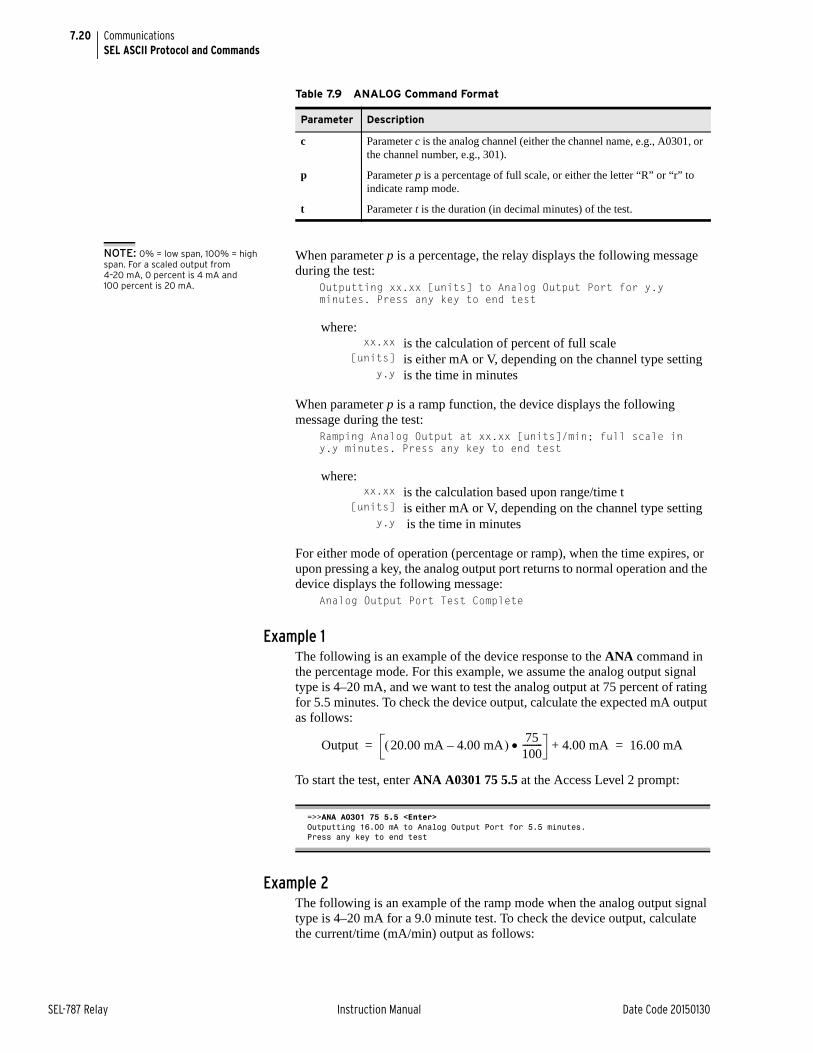
7.20
SEL-787 Relay Instruction Manual Date Code 20150130
CommunicationsSEL ASCII Protocol and Commands
NOTE: 0% = low span, 100% = high span. For a scaled output from 4–20 mA, 0 percent is 4 mA and 100 percent is 20 mA.
When parameter p is a percentage, the relay displays the following message during the test:
Outputting xx.xx [units] to Analog Output Port for y.y minutes. Press any key to end test
When parameter p is a ramp function, the device displays the following message during the test:
Ramping Analog Output at xx.xx [units]/min; full scale in y.y minutes. Press any key to end test
For either mode of operation (percentage or ramp), when the time expires, or upon pressing a key, the analog output port returns to normal operation and the device displays the following message:
Analog Output Port Test Complete
Example 1The following is an example of the device response to the ANA command in the percentage mode. For this example, we assume the analog output signal type is 4–20 mA, and we want to test the analog output at 75 percent of rating for 5.5 minutes. To check the device output, calculate the expected mA output as follows:
To start the test, enter ANA A0301 75 5.5 at the Access Level 2 prompt:
Example 2The following is an example of the ramp mode when the analog output signal type is 4–20 mA for a 9.0 minute test. To check the device output, calculate the current/time (mA/min) output as follows:
Table 7.9 ANALOG Command Format
Parameter Description
c Parameter c is the analog channel (either the channel name, e.g., A0301, or the channel number, e.g., 301).
p Parameter p is a percentage of full scale, or either the letter “R” or “r” to indicate ramp mode.
t Parameter t is the duration (in decimal minutes) of the test.
where:xx.xx is the calculation of percent of full scale
[units] is either mA or V, depending on the channel type settingy.y is the time in minutes
where:xx.xx is the calculation based upon range/time t
[units] is either mA or V, depending on the channel type settingy.y is the time in minutes
=>>ANA A0301 75 5.5 <Enter>Outputting 16.00 mA to Analog Output Port for 5.5 minutes.Press any key to end test
Output 20.00 mA 4.00 mA– 75100--------- 4.00 mA+ 16.00 mA= =
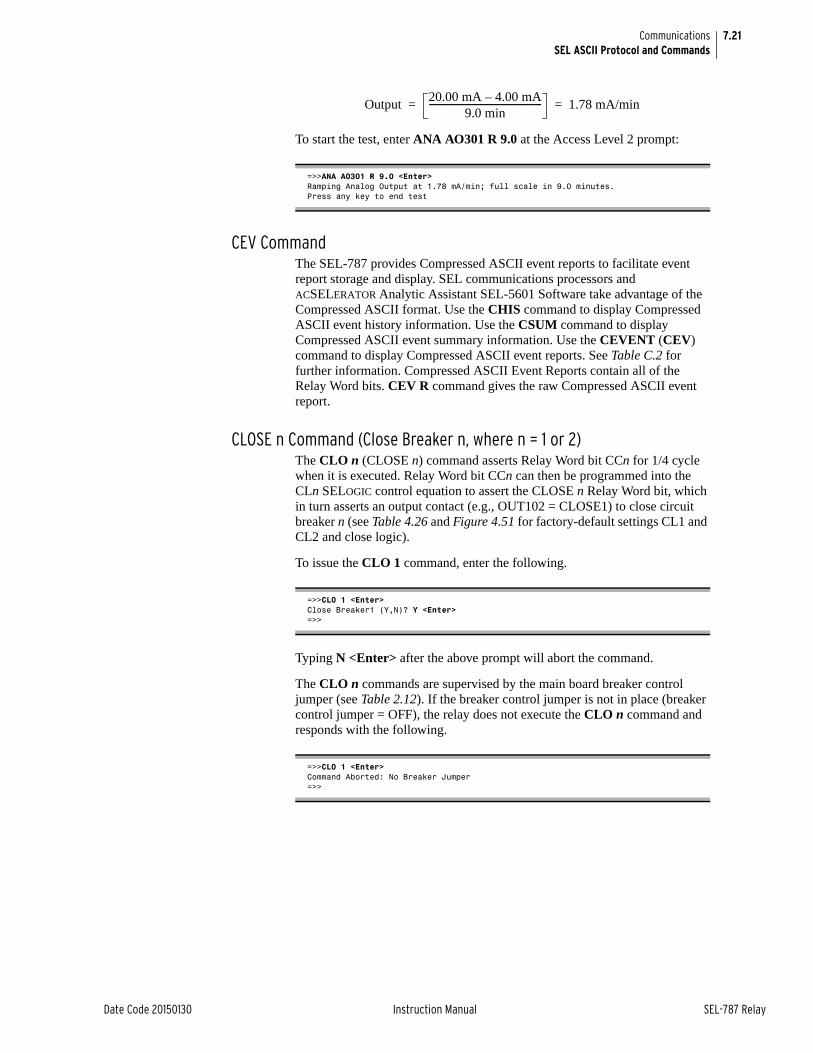
7.21
Date Code 20150130 Instruction Manual SEL-787 Relay
CommunicationsSEL ASCII Protocol and Commands
To start the test, enter ANA AO301 R 9.0 at the Access Level 2 prompt:
CEV CommandThe SEL-787 provides Compressed ASCII event reports to facilitate event report storage and display. SEL communications processors and ACSELERATOR Analytic Assistant SEL-5601 Software take advantage of the Compressed ASCII format. Use the CHIS command to display Compressed ASCII event history information. Use the CSUM command to display Compressed ASCII event summary information. Use the CEVENT (CEV) command to display Compressed ASCII event reports. See Table C.2 for further information. Compressed ASCII Event Reports contain all of the Relay Word bits. CEV R command gives the raw Compressed ASCII event report.
CLOSE n Command (Close Breaker n, where n = 1 or 2)The CLO n (CLOSE n) command asserts Relay Word bit CCn for 1/4 cycle when it is executed. Relay Word bit CCn can then be programmed into the CLn SELOGIC control equation to assert the CLOSE n Relay Word bit, which in turn asserts an output contact (e.g., OUT102 = CLOSE1) to close circuit breaker n (see Table 4.26 and Figure 4.51 for factory-default settings CL1 and CL2 and close logic).
To issue the CLO 1 command, enter the following.
Typing N <Enter> after the above prompt will abort the command.
The CLO n commands are supervised by the main board breaker control jumper (see Table 2.12). If the breaker control jumper is not in place (breaker control jumper = OFF), the relay does not execute the CLO n command and responds with the following.
=>>ANA AO301 R 9.0 <Enter>Ramping Analog Output at 1.78 mA/min; full scale in 9.0 minutes.Press any key to end test
Output20.00 mA 4.00 mA–
9.0 min--------------------------------------------------- 1.78 mA/min= =
=>>CLO 1 <Enter>Close Breaker1 (Y,N)? Y <Enter>=>>
=>>CLO 1 <Enter>Command Aborted: No Breaker Jumper=>>
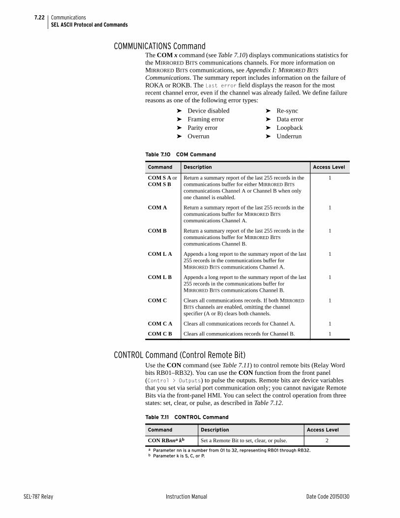
7.22
SEL-787 Relay Instruction Manual Date Code 20150130
CommunicationsSEL ASCII Protocol and Commands
COMMUNICATIONS CommandThe COM x command (see Table 7.10) displays communications statistics for the MIRRORED BITS communications channels. For more information on MIRRORED BITS communications, see Appendix I: MIRRORED BITS Communications. The summary report includes information on the failure of ROKA or ROKB. The Last error field displays the reason for the most recent channel error, even if the channel was already failed. We define failure reasons as one of the following error types:
CONTROL Command (Control Remote Bit)Use the CON command (see Table 7.11) to control remote bits (Relay Word bits RB01–RB32). You can use the CON function from the front panel (Control > Outputs) to pulse the outputs. Remote bits are device variables that you set via serial port communication only; you cannot navigate Remote Bits via the front-panel HMI. You can select the control operation from three states: set, clear, or pulse, as described in Table 7.12.
➤ Device disabled ➤ Re-sync➤ Framing error ➤ Data error➤ Parity error ➤ Loopback➤ Overrun ➤ Underrun
Table 7.10 COM Command
Command Description Access Level
COM S A or COM S B
Return a summary report of the last 255 records in the communications buffer for either MIRRORED BITS communications Channel A or Channel B when only one channel is enabled.
1
COM A Return a summary report of the last 255 records in the communications buffer for MIRRORED BITS communications Channel A.
1
COM B Return a summary report of the last 255 records in the communications buffer for MIRRORED BITS communications Channel B.
1
COM L A Appends a long report to the summary report of the last 255 records in the communications buffer for MIRRORED BITS communications Channel A.
1
COM L B Appends a long report to the summary report of the last 255 records in the communications buffer for MIRRORED BITS communications Channel B.
1
COM C Clears all communications records. If both MIRRORED BITS channels are enabled, omitting the channel specifier (A or B) clears both channels.
1
COM C A Clears all communications records for Channel A. 1
COM C B Clears all communications records for Channel B. 1
Table 7.11 CONTROL Command
Command Description Access Level
CON RBnna kb
a Parameter nn is a number from 01 to 32, representing RB01 through RB32.b Parameter k is S, C, or P.
Set a Remote Bit to set, clear, or pulse. 2
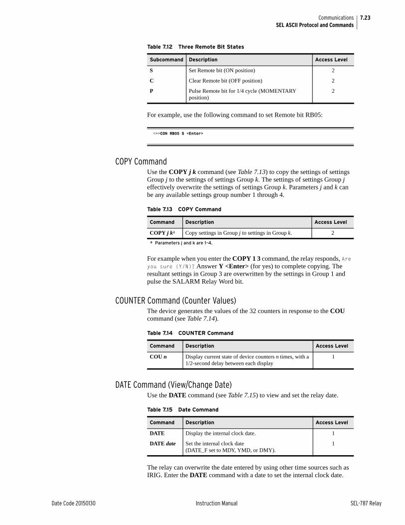
7.23
Date Code 20150130 Instruction Manual SEL-787 Relay
CommunicationsSEL ASCII Protocol and Commands
For example, use the following command to set Remote bit RB05:
COPY CommandUse the COPY j k command (see Table 7.13) to copy the settings of settings Group j to the settings of settings Group k. The settings of settings Group j effectively overwrite the settings of settings Group k. Parameters j and k can be any available settings group number 1 through 4.
For example when you enter the COPY 1 3 command, the relay responds, Are you sure (Y/N)? Answer Y <Enter> (for yes) to complete copying. The resultant settings in Group 3 are overwritten by the settings in Group 1 and pulse the SALARM Relay Word bit.
COUNTER Command (Counter Values)The device generates the values of the 32 counters in response to the COU command (see Table 7.14).
DATE Command (View/Change Date)Use the DATE command (see Table 7.15) to view and set the relay date.
The relay can overwrite the date entered by using other time sources such as IRIG. Enter the DATE command with a date to set the internal clock date.
Table 7.12 Three Remote Bit States
Subcommand Description Access Level
S Set Remote bit (ON position) 2
C Clear Remote bit (OFF position) 2
P Pulse Remote bit for 1/4 cycle (MOMENTARY position)
2
=>>CON RB05 S <Enter>
Table 7.13 COPY Command
Command Description Access Level
COPY j ka
a Parameters j and k are 1–4.
Copy settings in Group j to settings in Group k. 2
Table 7.14 COUNTER Command
Command Description Access Level
COU n Display current state of device counters n times, with a 1/2-second delay between each display
1
Table 7.15 Date Command
Command Description Access Level
DATE Display the internal clock date. 1
DATE date Set the internal clock date(DATE_F set to MDY, YMD, or DMY).
1
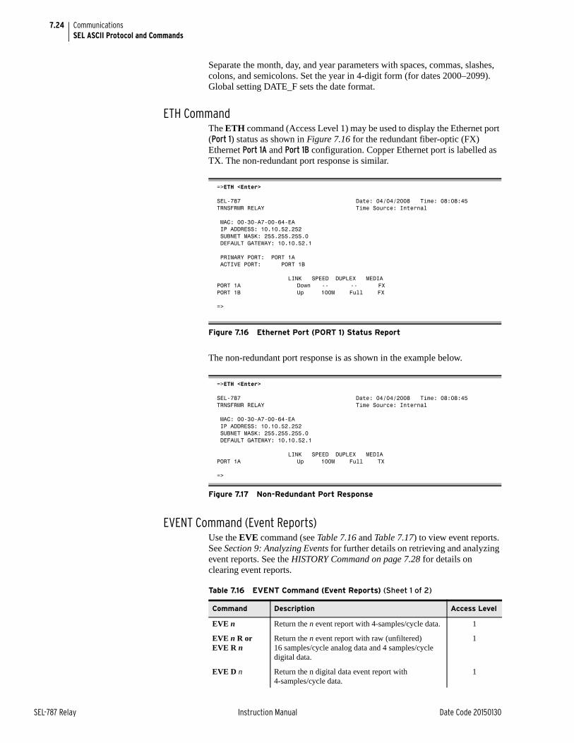
7.24
SEL-787 Relay Instruction Manual Date Code 20150130
CommunicationsSEL ASCII Protocol and Commands
Separate the month, day, and year parameters with spaces, commas, slashes, colons, and semicolons. Set the year in 4-digit form (for dates 2000–2099). Global setting DATE_F sets the date format.
ETH CommandThe ETH command (Access Level 1) may be used to display the Ethernet port (Port 1) status as shown in Figure 7.16 for the redundant fiber-optic (FX) Ethernet Port 1A and Port 1B configuration. Copper Ethernet port is labelled as TX. The non-redundant port response is similar.
The non-redundant port response is as shown in the example below.
EVENT Command (Event Reports)Use the EVE command (see Table 7.16 and Table 7.17) to view event reports. See Section 9: Analyzing Events for further details on retrieving and analyzing event reports. See the HISTORY Command on page 7.28 for details on clearing event reports.
=>ETH <Enter>
SEL-787 Date: 04/04/2008 Time: 08:08:45TRNSFRMR RELAY Time Source: Internal
MAC: 00-30-A7-00-64-EA IP ADDRESS: 10.10.52.252 SUBNET MASK: 255.255.255.0 DEFAULT GATEWAY: 10.10.52.1
PRIMARY PORT: PORT 1A ACTIVE PORT: PORT 1B
LINK SPEED DUPLEX MEDIAPORT 1A Down -- -- FX PORT 1B Up 100M Full FX
=>
Figure 7.16 Ethernet Port (PORT 1) Status Report
=>ETH <Enter>
SEL-787 Date: 04/04/2008 Time: 08:08:45TRNSFRMR RELAY Time Source: Internal
MAC: 00-30-A7-00-64-EA IP ADDRESS: 10.10.52.252 SUBNET MASK: 255.255.255.0 DEFAULT GATEWAY: 10.10.52.1
LINK SPEED DUPLEX MEDIAPORT 1A Up 100M Full TX
=>
Figure 7.17 Non-Redundant Port Response
Table 7.16 EVENT Command (Event Reports) (Sheet 1 of 2)
Command Description Access Level
EVE n Return the n event report with 4-samples/cycle data. 1
EVE n R orEVE R n
Return the n event report with raw (unfiltered) 16 samples/cycle analog data and 4 samples/cycle digital data.
1
EVE D n Return the n digital data event report with 4-samples/cycle data.
1
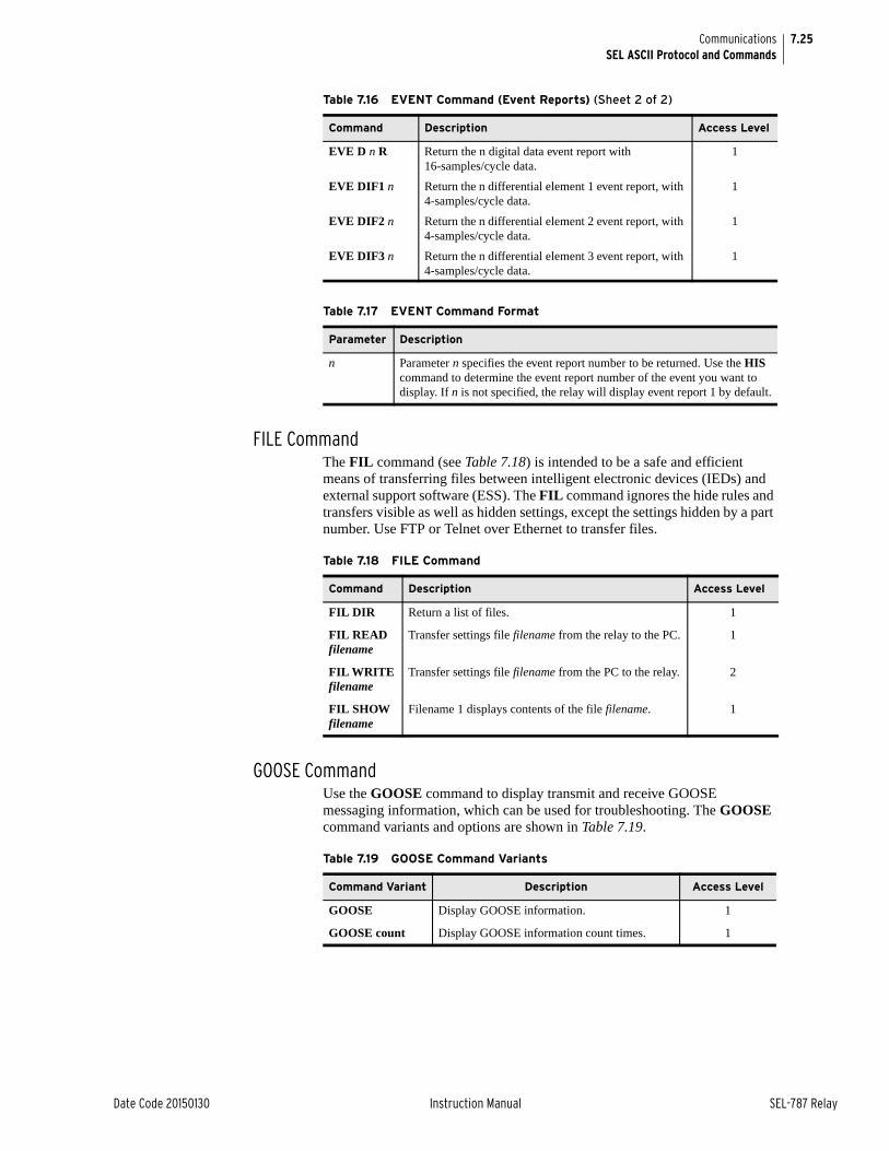
7.25
Date Code 20150130 Instruction Manual SEL-787 Relay
CommunicationsSEL ASCII Protocol and Commands
FILE CommandThe FIL command (see Table 7.18) is intended to be a safe and efficient means of transferring files between intelligent electronic devices (IEDs) and external support software (ESS). The FIL command ignores the hide rules and transfers visible as well as hidden settings, except the settings hidden by a part number. Use FTP or Telnet over Ethernet to transfer files.
GOOSE CommandUse the GOOSE command to display transmit and receive GOOSE messaging information, which can be used for troubleshooting. The GOOSE command variants and options are shown in Table 7.19.
EVE D n R Return the n digital data event report with 16-samples/cycle data.
1
EVE DIF1 n Return the n differential element 1 event report, with 4-samples/cycle data.
1
EVE DIF2 n Return the n differential element 2 event report, with 4-samples/cycle data.
1
EVE DIF3 n Return the n differential element 3 event report, with 4-samples/cycle data.
1
Table 7.17 EVENT Command Format
Parameter Description
n Parameter n specifies the event report number to be returned. Use the HIS command to determine the event report number of the event you want to display. If n is not specified, the relay will display event report 1 by default.
Table 7.16 EVENT Command (Event Reports) (Sheet 2 of 2)
Command Description Access Level
Table 7.18 FILE Command
Command Description Access Level
FIL DIR Return a list of files. 1
FIL READ filename
Transfer settings file filename from the relay to the PC. 1
FIL WRITE filename
Transfer settings file filename from the PC to the relay. 2
FIL SHOW filename
Filename 1 displays contents of the file filename. 1
Table 7.19 GOOSE Command Variants
Command Variant Description Access Level
GOOSE Display GOOSE information. 1
GOOSE count Display GOOSE information count times. 1
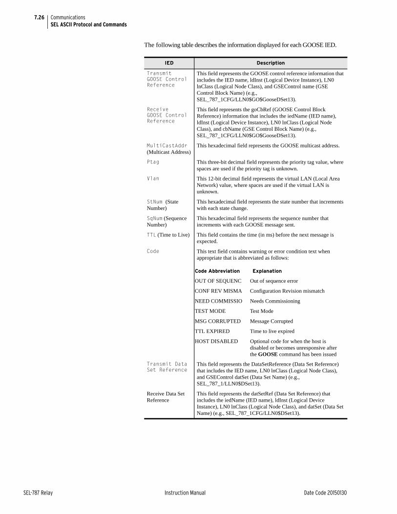
7.26
SEL-787 Relay Instruction Manual Date Code 20150130
CommunicationsSEL ASCII Protocol and Commands
The following table describes the information displayed for each GOOSE IED.
IED Description
TransmitGOOSE Control Reference
This field represents the GOOSE control reference information that includes the IED name, ldInst (Logical Device Instance), LN0 lnClass (Logical Node Class), and GSEControl name (GSE Control Block Name) (e.g., SEL_787_1CFG/LLN0$GO$GooseDSet13).
ReceiveGOOSE Control Reference
This field represents the goCbRef (GOOSE Control Block Reference) information that includes the iedName (IED name), ldInst (Logical Device Instance), LN0 lnClass (Logical Node Class), and cbName (GSE Control Block Name) (e.g., SEL_787_1CFG/LLN0$GO$GooseDSet13).
MultiCastAddr (Multicast Address)
This hexadecimal field represents the GOOSE multicast address.
Ptag This three-bit decimal field represents the priority tag value, where spaces are used if the priority tag is unknown.
Vlan This 12-bit decimal field represents the virtual LAN (Local Area Network) value, where spaces are used if the virtual LAN is unknown.
StNum (State Number)
This hexadecimal field represents the state number that increments with each state change.
SqNum (Sequence Number)
This hexadecimal field represents the sequence number that increments with each GOOSE message sent.
TTL (Time to Live) This field contains the time (in ms) before the next message is expected.
Code This text field contains warning or error condition text when appropriate that is abbreviated as follows:
Transmit Data Set Reference
This field represents the DataSetReference (Data Set Reference) that includes the IED name, LN0 lnClass (Logical Node Class), and GSEControl datSet (Data Set Name) (e.g., SEL_787_1/LLN0$DSet13).
Receive Data Set Reference
This field represents the datSetRef (Data Set Reference) that includes the iedName (IED name), ldInst (Logical Device Instance), LN0 lnClass (Logical Node Class), and datSet (Data Set Name) (e.g., SEL_787_1CFG/LLN0$DSet13).
Code Abbreviation Explanation
OUT OF SEQUENC Out of sequence error
CONF REV MISMA Configuration Revision mismatch
NEED COMMISSIO Needs Commissioning
TEST MODE Test Mode
MSG CORRUPTED Message Corrupted
TTL EXPIRED Time to live expired
HOST DISABLED Optional code for when the host is disabled or becomes unresponsive after the GOOSE command has been issued
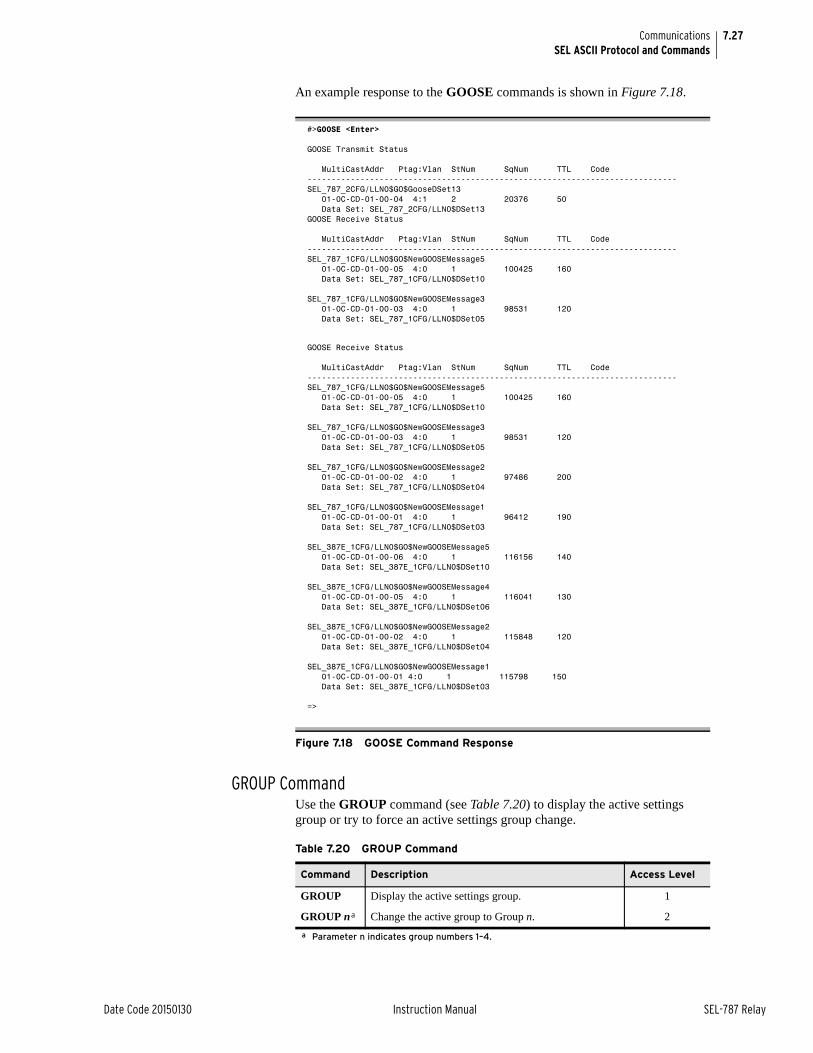
7.27
Date Code 20150130 Instruction Manual SEL-787 Relay
CommunicationsSEL ASCII Protocol and Commands
An example response to the GOOSE commands is shown in Figure 7.18.
GROUP CommandUse the GROUP command (see Table 7.20) to display the active settings group or try to force an active settings group change.
#>GOOSE <Enter>
GOOSE Transmit Status
MultiCastAddr Ptag:Vlan StNum SqNum TTL Code-----------------------------------------------------------------------------SEL_787_2CFG/LLN0$GO$GooseDSet13 01-0C-CD-01-00-04 4:1 2 20376 50 Data Set: SEL_787_2CFG/LLN0$DSet13GOOSE Receive Status
MultiCastAddr Ptag:Vlan StNum SqNum TTL Code-----------------------------------------------------------------------------SEL_787_1CFG/LLN0$GO$NewGOOSEMessage5 01-0C-CD-01-00-05 4:0 1 100425 160 Data Set: SEL_787_1CFG/LLN0$DSet10
SEL_787_1CFG/LLN0$GO$NewGOOSEMessage3 01-0C-CD-01-00-03 4:0 1 98531 120 Data Set: SEL_787_1CFG/LLN0$DSet05
GOOSE Receive Status
MultiCastAddr Ptag:Vlan StNum SqNum TTL Code-----------------------------------------------------------------------------SEL_787_1CFG/LLN0$GO$NewGOOSEMessage5 01-0C-CD-01-00-05 4:0 1 100425 160 Data Set: SEL_787_1CFG/LLN0$DSet10
SEL_787_1CFG/LLN0$GO$NewGOOSEMessage3 01-0C-CD-01-00-03 4:0 1 98531 120 Data Set: SEL_787_1CFG/LLN0$DSet05
SEL_787_1CFG/LLN0$GO$NewGOOSEMessage2 01-0C-CD-01-00-02 4:0 1 97486 200 Data Set: SEL_787_1CFG/LLN0$DSet04
SEL_787_1CFG/LLN0$GO$NewGOOSEMessage1 01-0C-CD-01-00-01 4:0 1 96412 190 Data Set: SEL_787_1CFG/LLN0$DSet03
SEL_387E_1CFG/LLN0$GO$NewGOOSEMessage5 01-0C-CD-01-00-06 4:0 1 116156 140 Data Set: SEL_387E_1CFG/LLN0$DSet10
SEL_387E_1CFG/LLN0$GO$NewGOOSEMessage4 01-0C-CD-01-00-05 4:0 1 116041 130 Data Set: SEL_387E_1CFG/LLN0$DSet06
SEL_387E_1CFG/LLN0$GO$NewGOOSEMessage2 01-0C-CD-01-00-02 4:0 1 115848 120 Data Set: SEL_387E_1CFG/LLN0$DSet04
SEL_387E_1CFG/LLN0$GO$NewGOOSEMessage1 01-0C-CD-01-00-01 4:0 1 115798 150 Data Set: SEL_387E_1CFG/LLN0$DSet03
=>
Figure 7.18 GOOSE Command Response
Table 7.20 GROUP Command
Command Description Access Level
GROUP Display the active settings group. 1
GROUP na
a Parameter n indicates group numbers 1–4.
Change the active group to Group n. 2
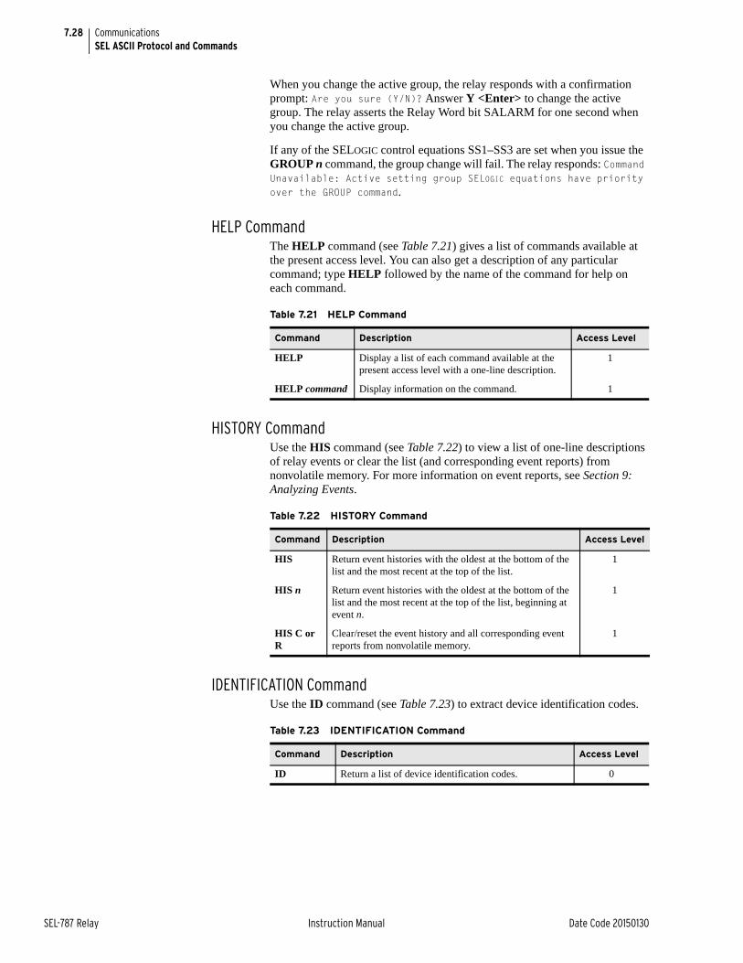
7.28
SEL-787 Relay Instruction Manual Date Code 20150130
CommunicationsSEL ASCII Protocol and Commands
When you change the active group, the relay responds with a confirmation prompt: Are you sure (Y/N)? Answer Y <Enter> to change the active group. The relay asserts the Relay Word bit SALARM for one second when you change the active group.
If any of the SELOGIC control equations SS1–SS3 are set when you issue the GROUP n command, the group change will fail. The relay responds: Command Unavailable: Active setting group SELOGIC equations have priority over the GROUP command.
HELP CommandThe HELP command (see Table 7.21) gives a list of commands available at the present access level. You can also get a description of any particular command; type HELP followed by the name of the command for help on each command.
HISTORY CommandUse the HIS command (see Table 7.22) to view a list of one-line descriptions of relay events or clear the list (and corresponding event reports) from nonvolatile memory. For more information on event reports, see Section 9: Analyzing Events.
IDENTIFICATION CommandUse the ID command (see Table 7.23) to extract device identification codes.
Table 7.21 HELP Command
Command Description Access Level
HELP Display a list of each command available at the present access level with a one-line description.
1
HELP command Display information on the command. 1
Table 7.22 HISTORY Command
Command Description Access Level
HIS Return event histories with the oldest at the bottom of the list and the most recent at the top of the list.
1
HIS n Return event histories with the oldest at the bottom of the list and the most recent at the top of the list, beginning at event n.
1
HIS C or R
Clear/reset the event history and all corresponding event reports from nonvolatile memory.
1
Table 7.23 IDENTIFICATION Command
Command Description Access Level
ID Return a list of device identification codes. 0
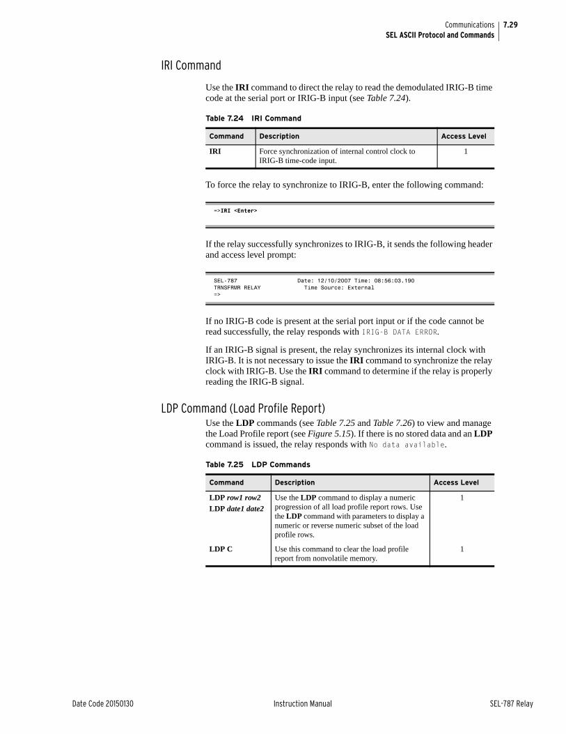
7.29
Date Code 20150130 Instruction Manual SEL-787 Relay
CommunicationsSEL ASCII Protocol and Commands
IRI Command
Use the IRI command to direct the relay to read the demodulated IRIG-B time code at the serial port or IRIG-B input (see Table 7.24).
To force the relay to synchronize to IRIG-B, enter the following command:
If the relay successfully synchronizes to IRIG-B, it sends the following header and access level prompt:
If no IRIG-B code is present at the serial port input or if the code cannot be read successfully, the relay responds with IRIG-B DATA ERROR.
If an IRIG-B signal is present, the relay synchronizes its internal clock with IRIG-B. It is not necessary to issue the IRI command to synchronize the relay clock with IRIG-B. Use the IRI command to determine if the relay is properly reading the IRIG-B signal.
LDP Command (Load Profile Report)Use the LDP commands (see Table 7.25 and Table 7.26) to view and manage the Load Profile report (see Figure 5.15). If there is no stored data and an LDP command is issued, the relay responds with No data available.
Table 7.24 IRI Command
Command Description Access Level
IRI Force synchronization of internal control clock to IRIG-B time-code input.
1
=>IRI <Enter>
SEL-787 Date: 12/10/2007 Time: 08:56:03.190TRNSFRMR RELAY Time Source: External=>
Table 7.25 LDP Commands
Command Description Access Level
LDP row1 row2LDP date1 date2
Use the LDP command to display a numeric progression of all load profile report rows. Use the LDP command with parameters to display a numeric or reverse numeric subset of the load profile rows.
1
LDP C Use this command to clear the load profile report from nonvolatile memory.
1
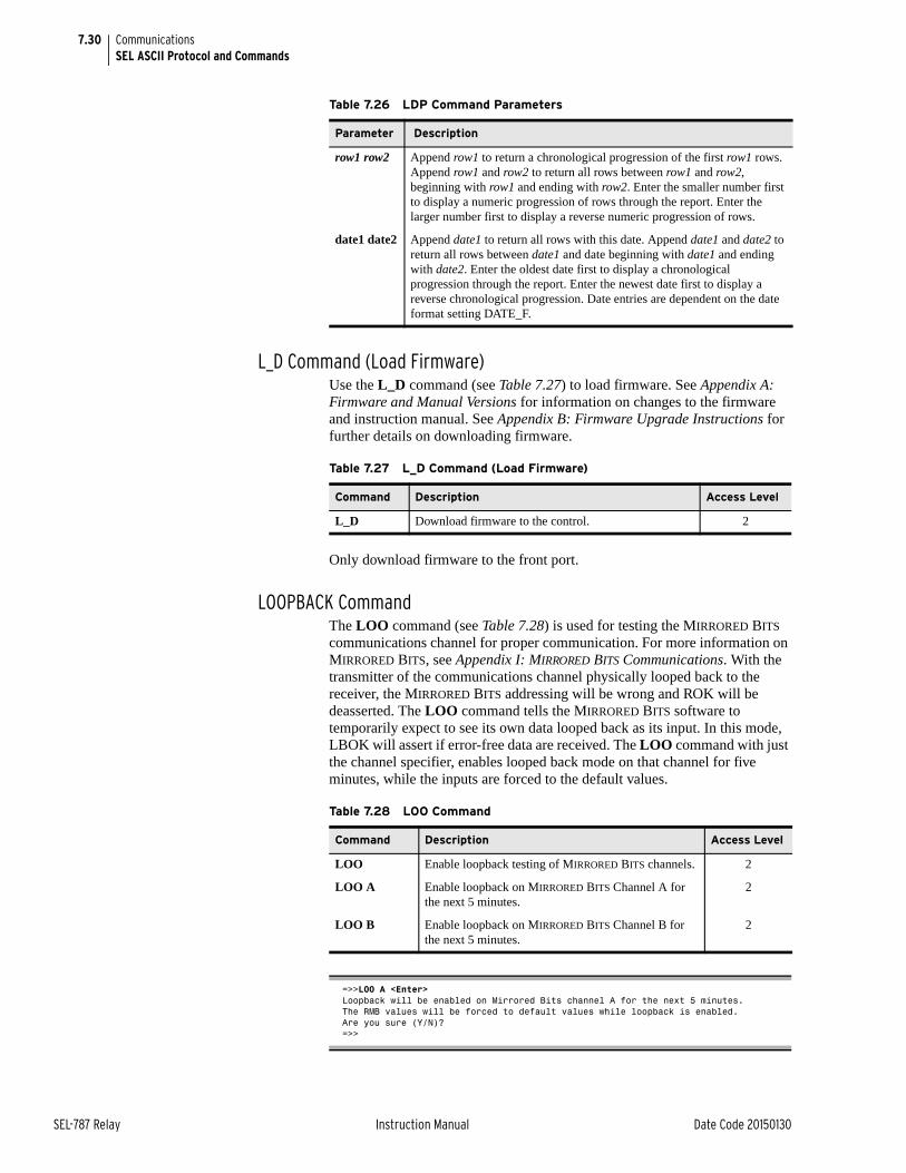
7.30
SEL-787 Relay Instruction Manual Date Code 20150130
CommunicationsSEL ASCII Protocol and Commands
L_D Command (Load Firmware)Use the L_D command (see Table 7.27) to load firmware. See Appendix A: Firmware and Manual Versions for information on changes to the firmware and instruction manual. See Appendix B: Firmware Upgrade Instructions for further details on downloading firmware.
Only download firmware to the front port.
LOOPBACK CommandThe LOO command (see Table 7.28) is used for testing the MIRRORED BITS communications channel for proper communication. For more information on MIRRORED BITS, see Appendix I: MIRRORED BITS Communications. With the transmitter of the communications channel physically looped back to the receiver, the MIRRORED BITS addressing will be wrong and ROK will be deasserted. The LOO command tells the MIRRORED BITS software to temporarily expect to see its own data looped back as its input. In this mode, LBOK will assert if error-free data are received. The LOO command with just the channel specifier, enables looped back mode on that channel for five minutes, while the inputs are forced to the default values.
.
Table 7.26 LDP Command Parameters
Parameter Description
row1 row2 Append row1 to return a chronological progression of the first row1 rows. Append row1 and row2 to return all rows between row1 and row2, beginning with row1 and ending with row2. Enter the smaller number first to display a numeric progression of rows through the report. Enter the larger number first to display a reverse numeric progression of rows.
date1 date2 Append date1 to return all rows with this date. Append date1 and date2 to return all rows between date1 and date beginning with date1 and ending with date2. Enter the oldest date first to display a chronological progression through the report. Enter the newest date first to display a reverse chronological progression. Date entries are dependent on the date format setting DATE_F.
Table 7.27 L_D Command (Load Firmware)
Command Description Access Level
L_D Download firmware to the control. 2
Table 7.28 LOO Command
Command Description Access Level
LOO Enable loopback testing of MIRRORED BITS channels. 2
LOO A Enable loopback on MIRRORED BITS Channel A for the next 5 minutes.
2
LOO B Enable loopback on MIRRORED BITS Channel B for the next 5 minutes.
2
=>>LOO A <Enter>Loopback will be enabled on Mirrored Bits channel A for the next 5 minutes.The RMB values will be forced to default values while loopback is enabled.Are you sure (Y/N)?=>>

7.31
Date Code 20150130 Instruction Manual SEL-787 Relay
CommunicationsSEL ASCII Protocol and Commands
If only one MIRRORED BITS port is enabled, the channel specifier (A or B) may be omitted. To enable loopback mode for other than the 5-minute default, enter the desired number of minutes (1–5000) as a command parameter. To allow the loopback data to modify the RMB values, include the DATA parameter.
To disable loopback mode before the selected number of minutes, re-issue the LOO command with the R parameter. The R parameter returns the device to normal operation. If both MIRRORED BITS channels are enabled, omitting the channel specifier in the disable command will cause both channels to be disabled.
MAC CommandUse the MAC command to display the MAC addresses of PORT 1, as shown below.
MET Command (Metering Data)The MET command (see Table 7.29, Table 7.30, and Table 7.31) provides access to the relay metering data.
=>>LOO 10 DATA <Enter>Loopback will be enabled on Mirrored Bits channel A for the next 10 minutes.The RMB values will be allowed to change while loopback is enabled.Are you sure (Y/N)? N <Enter>Canceled.=>>
=>>LOO R <Enter>Loopback is disabled on both channels.=>>
=>MAC <Enter>Port 1 MAC Address: 00-30-A7-00-00-00=>
Table 7.29 Meter Command
Command Description Access Level
MET c n Display metering data. 1
MET c R Reset metering data. 2
Table 7.30 Meter Command Parameters
Parameter Description
c Parameter for identifying meter class.
n Parameter used to specify number of times (1–32767) to repeat the meter response.
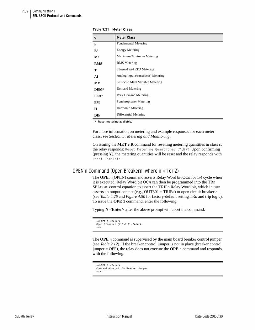
7.32
SEL-787 Relay Instruction Manual Date Code 20150130
CommunicationsSEL ASCII Protocol and Commands
For more information on metering and example responses for each meter class, see Section 5: Metering and Monitoring.
On issuing the MET c R command for resetting metering quantities in class c, the relay responds: Reset Metering Quantities (Y,N)? Upon confirming (pressing Y), the metering quantities will be reset and the relay responds with Reset Complete.
OPEN n Command (Open Breakern, where n = 1 or 2)The OPE n (OPEN) command asserts Relay Word bit OCn for 1/4 cycle when it is executed. Relay Word bit OCn can then be programmed into the TRn SELOGIC control equation to assert the TRIPn Relay Word bit, which in turn asserts an output contact (e.g., OUT301 = TRIPn) to open circuit breaker n (see Table 4.26 and Figure 4.50 for factory-default setting TRn and trip logic).To issue the OPE 1 command, enter the following.
Typing N <Enter> after the above prompt will abort the command.
The OPE n command is supervised by the main board breaker control jumper (see Table 2.12). If the breaker control jumper is not in place (breaker control jumper = OFF), the relay does not execute the OPE n command and responds with the following.
Table 7.31 Meter Class
c Meter Class
F Fundamental Metering
Ea
a Reset metering available.
Energy Metering
Ma Maximum/Minimum Metering
RMS RMS Metering
T Thermal and RTD Metering
AI Analog Input (transducer) Metering
MV SELOGIC Math Variable Metering
DEMa Demand Metering
PEAa Peak Demand Metering
PM Synchrophasor Metering
H Harmonic Metering
DIF Differential Metering
=>>OPE 1 <Enter>Open Breaker1 (Y,N)? Y <Enter>=>>
=>>OPE 1 <Enter>Command Aborted: No Breaker Jumper=>>
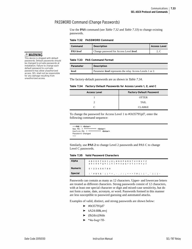
7.33
Date Code 20150130 Instruction Manual SEL-787 Relay
CommunicationsSEL ASCII Protocol and Commands
PASSWORD Command (Change Passwords)
Use the PAS command (see Table 7.32 and Table 7.33) to change existing passwords.
The factory-default passwords are as shown in Table 7.34.
To change the password for Access Level 1 to #Ot3579!ijd7, enter the following command sequence:
Similarly, use PAS 2 to change Level 2 passwords and PAS C to change Level C passwords.
Passwords can contain as many as 12 characters. Upper- and lowercase letters are treated as different characters. Strong passwords consist of 12 characters, with at least one special character or digit and mixed-case sensitivity, but do not form a name, date, acronym, or word. Passwords formed in this manner are less susceptible to password guessing and automated attacks.
Examples of valid, distinct, and strong passwords are shown below:
➤ #0t3579!ijd7
➤ $A24.68&,mvj
➤ (Ih2dcs)36dn
➤ *4u-Iwg+?lf-
Table 7.32 PASSWORD Command
Command Description Access Level
PAS level Change password for Access Level level. 2, C
Table 7.33 PAS Command Format
Parameter Description
level Parameter level represents the relay Access Levels 1 or 2.
Table 7.34 Factory-Default Passwords for Access Levels 1, 2, and C
Access Level Factory-Default Password
1 OTTER
2 TAIL
C CLARKE
=>>PAS 1 <Enter>New PW: ? *********** <Enter>Confirm PW: ? *********** <Enter>Password Changed=>>
Table 7.35 Valid Password Characters
Alpha A B C D E F G H I J K L M N O P Q R S T U V W X Y Za b c d e f g h i j k l m n o p q r s t u v w x y z
Numeric 0 1 2 3 4 5 6 7 8 9
Special ! " # $ % & ' ( ) * + , - . / : ; < = > ? @ [ \ ] ^ _ ` { | } ~
WARNINGThis device is shipped with default passwords. Default passwords should be changed to private passwords at installation. Failure to change each default password to a private password may allow unauthorized access. SEL shall not be responsible for any damage resulting from unauthorized access.
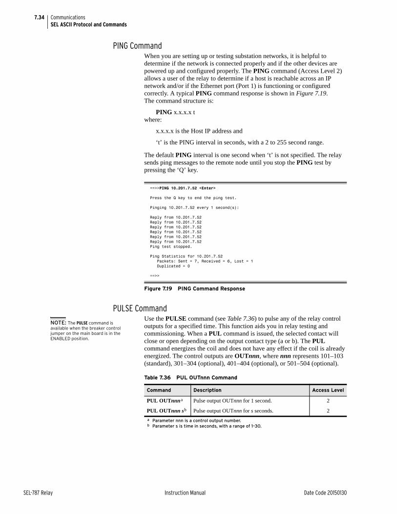
7.34
SEL-787 Relay Instruction Manual Date Code 20150130
CommunicationsSEL ASCII Protocol and Commands
PING CommandWhen you are setting up or testing substation networks, it is helpful to determine if the network is connected properly and if the other devices are powered up and configured properly. The PING command (Access Level 2) allows a user of the relay to determine if a host is reachable across an IP network and/or if the Ethernet port (Port 1) is functioning or configured correctly. A typical PING command response is shown in Figure 7.19. The command structure is:
PING x.x.x.x t where:
x.x.x.x is the Host IP address and
‘t’ is the PING interval in seconds, with a 2 to 255 second range.
The default PING interval is one second when ‘t’ is not specified. The relay sends ping messages to the remote node until you stop the PING test by pressing the ‘Q’ key.
PULSE CommandUse the PULSE command (see Table 7.36) to pulse any of the relay control outputs for a specified time. This function aids you in relay testing and commissioning. When a PUL command is issued, the selected contact will close or open depending on the output contact type (a or b). The PUL command energizes the coil and does not have any effect if the coil is already energized. The control outputs are OUTnnn, where nnn represents 101–103 (standard), 301–304 (optional), 401–404 (optional), or 501–504 (optional).
==>>PING 10.201.7.52 <Enter>
Press the Q key to end the ping test.
Pinging 10.201.7.52 every 1 second(s):
Reply from 10.201.7.52Reply from 10.201.7.52Reply from 10.201.7.52Reply from 10.201.7.52Reply from 10.201.7.52Reply from 10.201.7.52Ping test stopped.
Ping Statistics for 10.201.7.52 Packets: Sent = 7, Received = 6, Lost = 1 Duplicated = 0
==>>
Figure 7.19 PING Command Response
Table 7.36 PUL OUTnnn Command
Command Description Access Level
PUL OUTnnna
a Parameter nnn is a control output number.
Pulse output OUTnnn for 1 second. 2
PUL OUTnnn sb
b Parameter s is time in seconds, with a range of 1–30.
Pulse output OUTnnn for s seconds. 2
NOTE: The PULSE command is available when the breaker control jumper on the main board is in the ENABLED position.
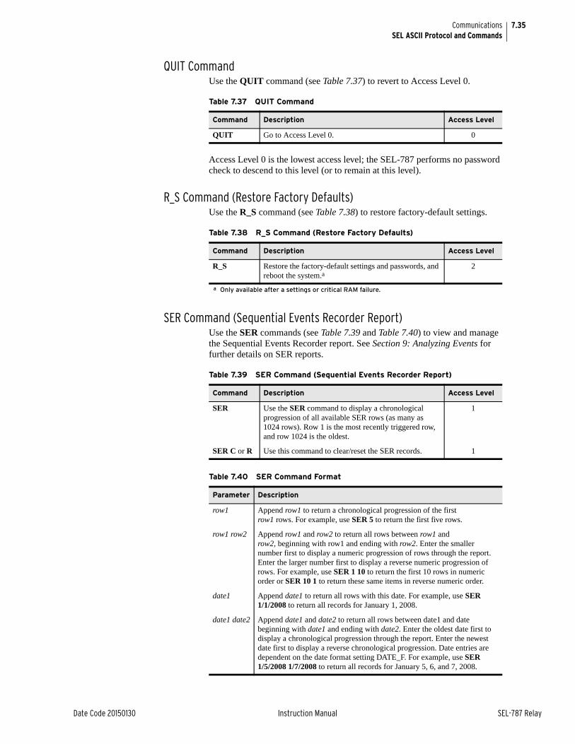
7.35
Date Code 20150130 Instruction Manual SEL-787 Relay
CommunicationsSEL ASCII Protocol and Commands
QUIT CommandUse the QUIT command (see Table 7.37) to revert to Access Level 0.
Access Level 0 is the lowest access level; the SEL-787 performs no password check to descend to this level (or to remain at this level).
R_S Command (Restore Factory Defaults)Use the R_S command (see Table 7.38) to restore factory-default settings.
SER Command (Sequential Events Recorder Report)Use the SER commands (see Table 7.39 and Table 7.40) to view and manage the Sequential Events Recorder report. See Section 9: Analyzing Events for further details on SER reports.
Table 7.37 QUIT Command
Command Description Access Level
QUIT Go to Access Level 0. 0
Table 7.38 R_S Command (Restore Factory Defaults)
Command Description Access Level
R_S Restore the factory-default settings and passwords, and reboot the system.a
a Only available after a settings or critical RAM failure.
2
Table 7.39 SER Command (Sequential Events Recorder Report)
Command Description Access Level
SER Use the SER command to display a chronological progression of all available SER rows (as many as 1024 rows). Row 1 is the most recently triggered row, and row 1024 is the oldest.
1
SER C or R Use this command to clear/reset the SER records. 1
Table 7.40 SER Command Format
Parameter Description
row1 Append row1 to return a chronological progression of the first row1 rows. For example, use SER 5 to return the first five rows.
row1 row2 Append row1 and row2 to return all rows between row1 and row2, beginning with row1 and ending with row2. Enter the smaller number first to display a numeric progression of rows through the report. Enter the larger number first to display a reverse numeric progression of rows. For example, use SER 1 10 to return the first 10 rows in numeric order or SER 10 1 to return these same items in reverse numeric order.
date1 Append date1 to return all rows with this date. For example, use SER 1/1/2008 to return all records for January 1, 2008.
date1 date2 Append date1 and date2 to return all rows between date1 and date beginning with date1 and ending with date2. Enter the oldest date first to display a chronological progression through the report. Enter the newest date first to display a reverse chronological progression. Date entries are dependent on the date format setting DATE_F. For example, use SER 1/5/2008 1/7/2008 to return all records for January 5, 6, and 7, 2008.
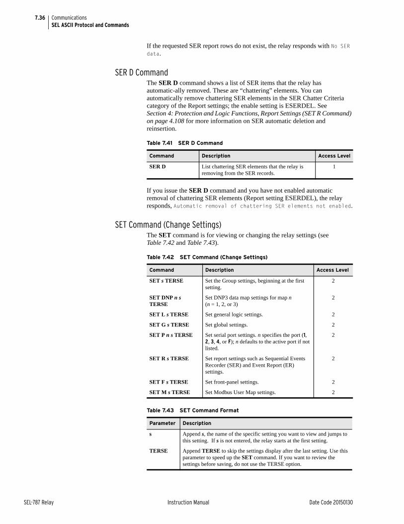
7.36
SEL-787 Relay Instruction Manual Date Code 20150130
CommunicationsSEL ASCII Protocol and Commands
If the requested SER report rows do not exist, the relay responds with No SER data.
SER D CommandThe SER D command shows a list of SER items that the relay has automatic-ally removed. These are “chattering” elements. You can automatically remove chattering SER elements in the SER Chatter Criteria category of the Report settings; the enable setting is ESERDEL. See Section 4: Protection and Logic Functions, Report Settings (SET R Command) on page 4.108 for more information on SER automatic deletion and reinsertion.
If you issue the SER D command and you have not enabled automatic removal of chattering SER elements (Report setting ESERDEL), the relay responds, Automatic removal of chattering SER elements not enabled.
SET Command (Change Settings)The SET command is for viewing or changing the relay settings (see Table 7.42 and Table 7.43).
Table 7.41 SER D Command
Command Description Access Level
SER D List chattering SER elements that the relay is removing from the SER records.
1
Table 7.42 SET Command (Change Settings)
Command Description Access Level
SET s TERSE Set the Group settings, beginning at the first setting.
2
SET DNP n s TERSE
Set DNP3 data map settings for map n (n = 1, 2, or 3)
2
SET L s TERSE Set general logic settings. 2
SET G s TERSE Set global settings. 2
SET P n s TERSE Set serial port settings. n specifies the port (1, 2, 3, 4, or F); n defaults to the active port if not listed.
2
SET R s TERSE Set report settings such as Sequential Events Recorder (SER) and Event Report (ER) settings.
2
SET F s TERSE Set front-panel settings. 2
SET M s TERSE Set Modbus User Map settings. 2
Table 7.43 SET Command Format
Parameter Description
s Append s, the name of the specific setting you want to view and jumps to this setting. If s is not entered, the relay starts at the first setting.
TERSE Append TERSE to skip the settings display after the last setting. Use this parameter to speed up the SET command. If you want to review the settings before saving, do not use the TERSE option.
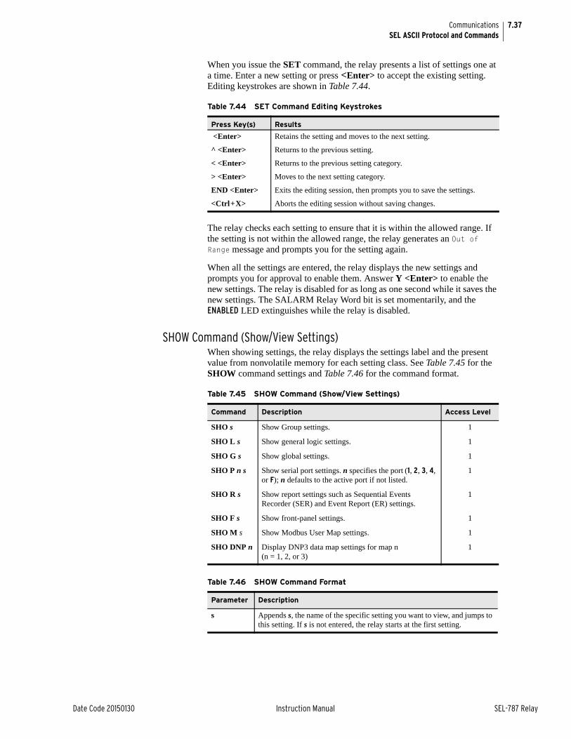
7.37
Date Code 20150130 Instruction Manual SEL-787 Relay
CommunicationsSEL ASCII Protocol and Commands
When you issue the SET command, the relay presents a list of settings one at a time. Enter a new setting or press <Enter> to accept the existing setting. Editing keystrokes are shown in Table 7.44.
The relay checks each setting to ensure that it is within the allowed range. If the setting is not within the allowed range, the relay generates an Out of Range message and prompts you for the setting again.
When all the settings are entered, the relay displays the new settings and prompts you for approval to enable them. Answer Y <Enter> to enable the new settings. The relay is disabled for as long as one second while it saves the new settings. The SALARM Relay Word bit is set momentarily, and the ENABLED LED extinguishes while the relay is disabled.
SHOW Command (Show/View Settings)When showing settings, the relay displays the settings label and the present value from nonvolatile memory for each setting class. See Table 7.45 for the SHOW command settings and Table 7.46 for the command format.
Table 7.44 SET Command Editing Keystrokes
Press Key(s) Results
<Enter> Retains the setting and moves to the next setting.
^ <Enter> Returns to the previous setting.
< <Enter> Returns to the previous setting category.
> <Enter> Moves to the next setting category.
END <Enter> Exits the editing session, then prompts you to save the settings.
<Ctrl+X> Aborts the editing session without saving changes.
Table 7.45 SHOW Command (Show/View Settings)
Command Description Access Level
SHO s Show Group settings. 1
SHO L s Show general logic settings. 1
SHO G s Show global settings. 1
SHO P n s Show serial port settings. n specifies the port (1, 2, 3, 4, or F); n defaults to the active port if not listed.
1
SHO R s Show report settings such as Sequential Events Recorder (SER) and Event Report (ER) settings.
1
SHO F s Show front-panel settings. 1
SHO M s Show Modbus User Map settings. 1
SHO DNP n Display DNP3 data map settings for map n (n = 1, 2, or 3)
1
Table 7.46 SHOW Command Format
Parameter Description
s Appends s, the name of the specific setting you want to view, and jumps to this setting. If s is not entered, the relay starts at the first setting.
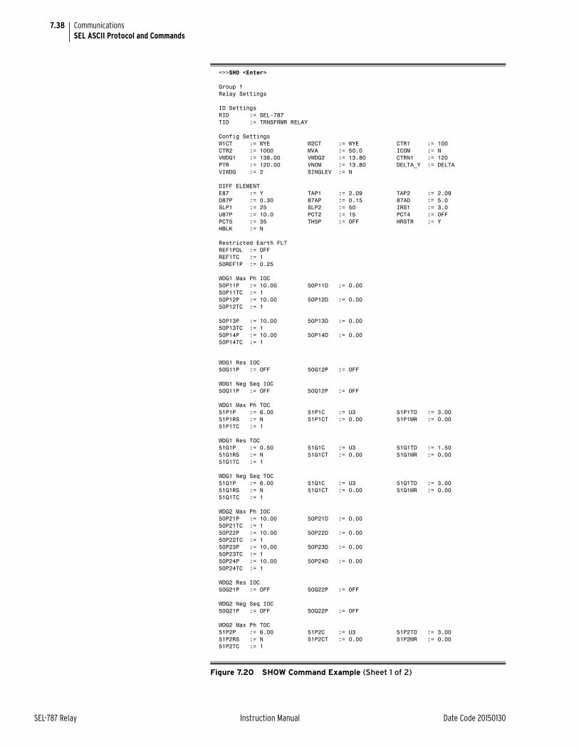
7.38
SEL-787 Relay Instruction Manual Date Code 20150130
CommunicationsSEL ASCII Protocol and Commands
=>>SHO <Enter>
Group 1Relay Settings
ID SettingsRID := SEL-787TID := TRNSFRMR RELAY
Config SettingsW1CT := WYE W2CT := WYE CTR1 := 100CTR2 := 1000 MVA := 50.0 ICOM := NVWDG1 := 138.00 VWDG2 := 13.80 CTRN1 := 120PTR := 120.00 VNOM := 13.80 DELTA_Y := DELTAVIWDG := 2 SINGLEV := N
DIFF ELEMENTE87 := Y TAP1 := 2.09 TAP2 := 2.09O87P := 0.30 87AP := 0.15 87AD := 5.0SLP1 := 25 SLP2 := 50 IRS1 := 3.0U87P := 10.0 PCT2 := 15 PCT4 := OFFPCT5 := 35 TH5P := OFF HRSTR := YHBLK := N
Restricted Earth FLTREF1POL := OFFREF1TC := 150REF1P := 0.25
WDG1 Max Ph IOC50P11P := 10.00 50P11D := 0.0050P11TC := 150P12P := 10.00 50P12D := 0.0050P12TC := 1
50P13P := 10.00 50P13D := 0.0050P13TC := 150P14P := 10.00 50P14D := 0.0050P14TC := 1
WDG1 Res IOC50G11P := OFF 50G12P := OFF
WDG1 Neg Seq IOC50Q11P := OFF 50Q12P := OFF
WDG1 Max Ph TOC51P1P := 6.00 51P1C := U3 51P1TD := 3.0051P1RS := N 51P1CT := 0.00 51P1MR := 0.0051P1TC := 1
WDG1 Res TOC51G1P := 0.50 51G1C := U3 51G1TD := 1.5051G1RS := N 51G1CT := 0.00 51G1MR := 0.0051G1TC := 1
WDG1 Neg Seq TOC51Q1P := 6.00 51Q1C := U3 51Q1TD := 3.0051Q1RS := N 51Q1CT := 0.00 51Q1MR := 0.0051Q1TC := 1
WDG2 Max Ph IOC50P21P := 10.00 50P21D := 0.0050P21TC := 150P22P := 10.00 50P22D := 0.0050P22TC := 150P23P := 10.00 50P23D := 0.0050P23TC := 150P24P := 10.00 50P24D := 0.0050P24TC := 1
WDG2 Res IOC50G21P := OFF 50G22P := OFF
WDG2 Neg Seq IOC50Q21P := OFF 50Q22P := OFF
WDG2 Max Ph TOC51P2P := 6.00 51P2C := U3 51P2TD := 3.0051P2RS := N 51P2CT := 0.00 51P2MR := 0.0051P2TC := 1
Figure 7.20 SHOW Command Example (Sheet 1 of 2)
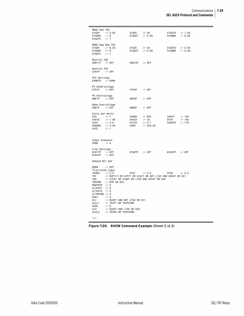
7.39
Date Code 20150130 Instruction Manual SEL-787 Relay
CommunicationsSEL ASCII Protocol and Commands
WDG2 Res TOC51G2P := 0.50 51G2C := U3 51G2TD := 1.5051G2RS := N 51G2CT := 0.00 51G2MR := 0.0051G2TC := 1
WDG2 Neg Seq TOC51Q2P := 6.00 51Q2C := U3 51Q2TD := 3.0051Q2RS := N 51Q2CT := 0.00 51Q2MR := 0.0051Q2TC := 1
Neutral IOC50N11P := OFF 50N12P := OFF
Neutral TOC51N1P := OFF
RTD SettingsE49RTD := NONE
Ph Undervoltage27P1P := OFF 27P2P := OFF
Ph Overvoltage59P1P := OFF 59P2P := OFF
NSeq Overvoltage59Q1P := OFF 59Q2P := OFF
Volts per HertzE24 := Y 24WDG := WYE 24D1P := 10524D1D := 1.00 24CCS := ID 24IP := 10524IC := 2.0 24ITD := 0.1 24D2P2 := 17624D2D2 := 3.00 24CR := 240.0024TC := 1
Power ElementsEPWR := N
Freq Settings81D1TP := OFF 81D2TP := OFF 81D3TP := OFF81D4TP := OFF
Demand Mtr Set
EDEM := OFFTrip/Close LogicTDURD := 0.5 CFD1 := 0.5 CFD2 := 0.5TR1 := 50P11T OR 51P1T OR 51Q1T OR NOT LT02 AND SV04T OR OC1TR2 := 51P2T OR 51Q2T OR LT02 AND SV04T OR OC2TRXFMR := 87R OR 87UREMTRIP := 0ULTRIP1 := 0ULTRIP2 := 0ULTRXFMR := 052A1 := 0CL1 := SV03T AND NOT LT02 OR CC1ULCL1 := TRIP1 OR TRIPXFMR52A2 := 0CL2 := SV03T AND LT02 OR CC2ULCL2 := TRIP2 OR TRIPXFMR
=>>
Figure 7.20 SHOW Command Example (Sheet 2 of 2)
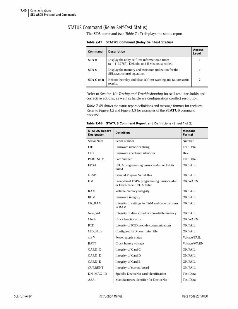
7.40
SEL-787 Relay Instruction Manual Date Code 20150130
CommunicationsSEL ASCII Protocol and Commands
STATUS Command (Relay Self-Test Status)The STA command (see Table 7.47) displays the status report.
Refer to Section 10: Testing and Troubleshooting for self-test thresholds and corrective actions, as well as hardware configuration conflict resolution.
Table 7.48 shows the status report definitions and message formats for each test. Refer to Figure 1.2 and Figure 1.3 for examples of the STATUS command response.
Table 7.47 STATUS Command (Relay Self-Test Status)
Command DescriptionAccess Level
STA n Display the relay self-test information n times (n = 1–32767). Defaults to 1 if n is not specified.
1
STA S Display the memory and execution utilization for the SELOGIC control equations.
1
STA C or R Reboot the relay and clear self-test warning and failure status results.
2
Table 7.48 STATUS Command Report and Definitions (Sheet 1 of 2)
STATUS Report Designator
DefinitionMessage Format
Serial Num Serial number Number
FID Firmware identifier string Text Data
CID Firmware checksum identifier Hex
PART NUM Part number Text Data
FPGA FPGA programming unsuccessful, or FPGA failed
OK/FAIL
GPSB General Purpose Serial Bus OK/FAIL
HMI Front-Panel FGPA programming unsuccessful, or Front-Panel FPGA failed
OK/WARN
RAM Volatile memory integrity OK/FAIL
ROM Firmware integrity OK/FAIL
CR_RAM Integrity of settings in RAM and code that runs in RAM
OK/FAIL
Non_Vol Integrity of data stored in nonvolatile memory OK/FAIL
Clock Clock functionality OK/WARN
RTD Integrity of RTD module/communications OK/FAIL
CID_FILE Configured IED description file OK/FAIL
x.x V Power supply status Voltage/FAIL
BATT Clock battery voltage Voltage/WARN
CARD_C Integrity of Card C OK/FAIL
CARD_D Integrity of Card D OK/FAIL
CARD_E Integrity of Card E OK/FAIL
CURRENT Integrity of current board OK/FAIL
DN_MAC_ID Specific DeviceNet card identification Text Data
ASA Manufacturers identifier for DeviceNet Text Data
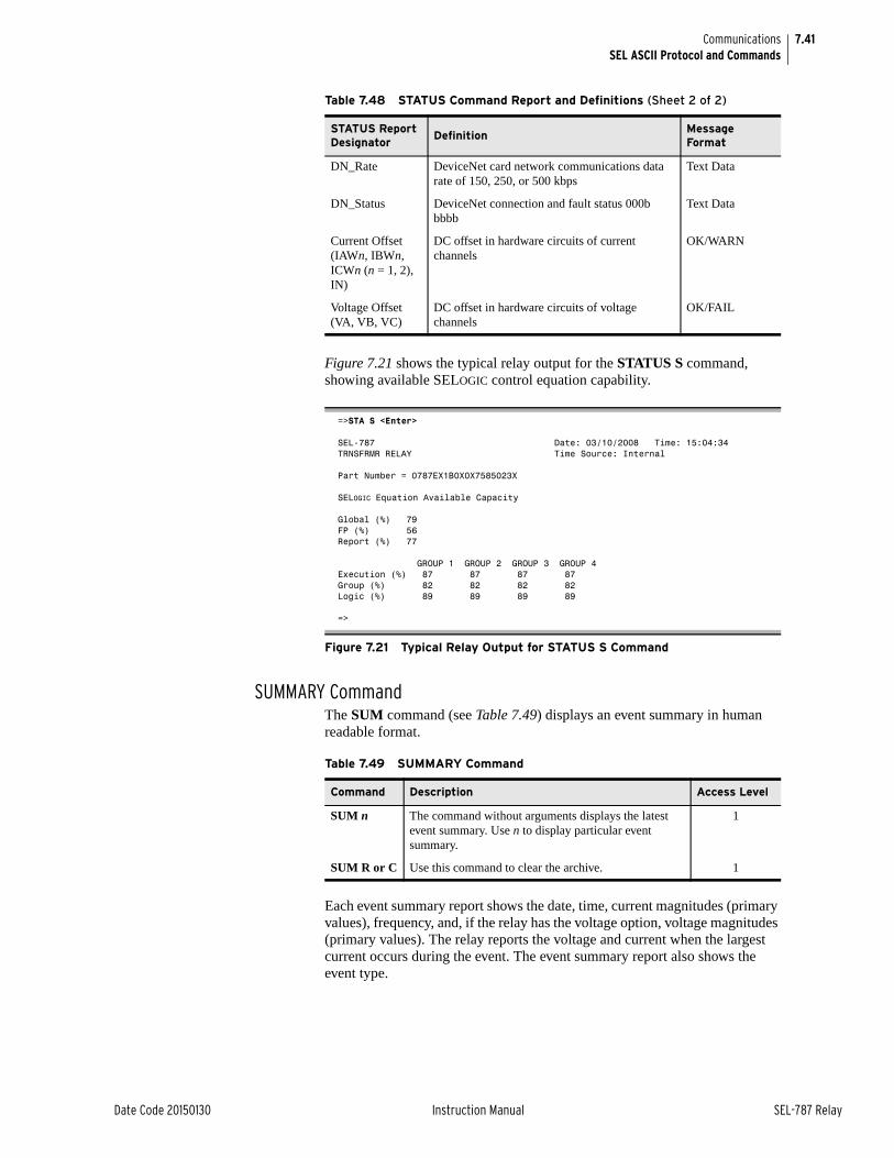
7.41
Date Code 20150130 Instruction Manual SEL-787 Relay
CommunicationsSEL ASCII Protocol and Commands
Figure 7.21 shows the typical relay output for the STATUS S command, showing available SELOGIC control equation capability.
SUMMARY CommandThe SUM command (see Table 7.49) displays an event summary in human readable format.
Each event summary report shows the date, time, current magnitudes (primary values), frequency, and, if the relay has the voltage option, voltage magnitudes (primary values). The relay reports the voltage and current when the largest current occurs during the event. The event summary report also shows the event type.
DN_Rate DeviceNet card network communications data rate of 150, 250, or 500 kbps
Text Data
DN_Status DeviceNet connection and fault status 000b bbbb
Text Data
Current Offset(IAWn, IBWn, ICWn (n = 1, 2), IN)
DC offset in hardware circuits of current channels
OK/WARN
Voltage Offset(VA, VB, VC)
DC offset in hardware circuits of voltage channels
OK/FAIL
=>STA S <Enter>
SEL-787 Date: 03/10/2008 Time: 15:04:34TRNSFRMR RELAY Time Source: Internal
Part Number = 0787EX1B0X0X7585023X
SELOGIC Equation Available Capacity
Global (%) 79FP (%) 56Report (%) 77
GROUP 1 GROUP 2 GROUP 3 GROUP 4Execution (%) 87 87 87 87Group (%) 82 82 82 82Logic (%) 89 89 89 89
=>
Figure 7.21 Typical Relay Output for STATUS S Command
Table 7.48 STATUS Command Report and Definitions (Sheet 2 of 2)
STATUS Report Designator
DefinitionMessage Format
Table 7.49 SUMMARY Command
Command Description Access Level
SUM n The command without arguments displays the latest event summary. Use n to display particular event summary.
1
SUM R or C Use this command to clear the archive. 1
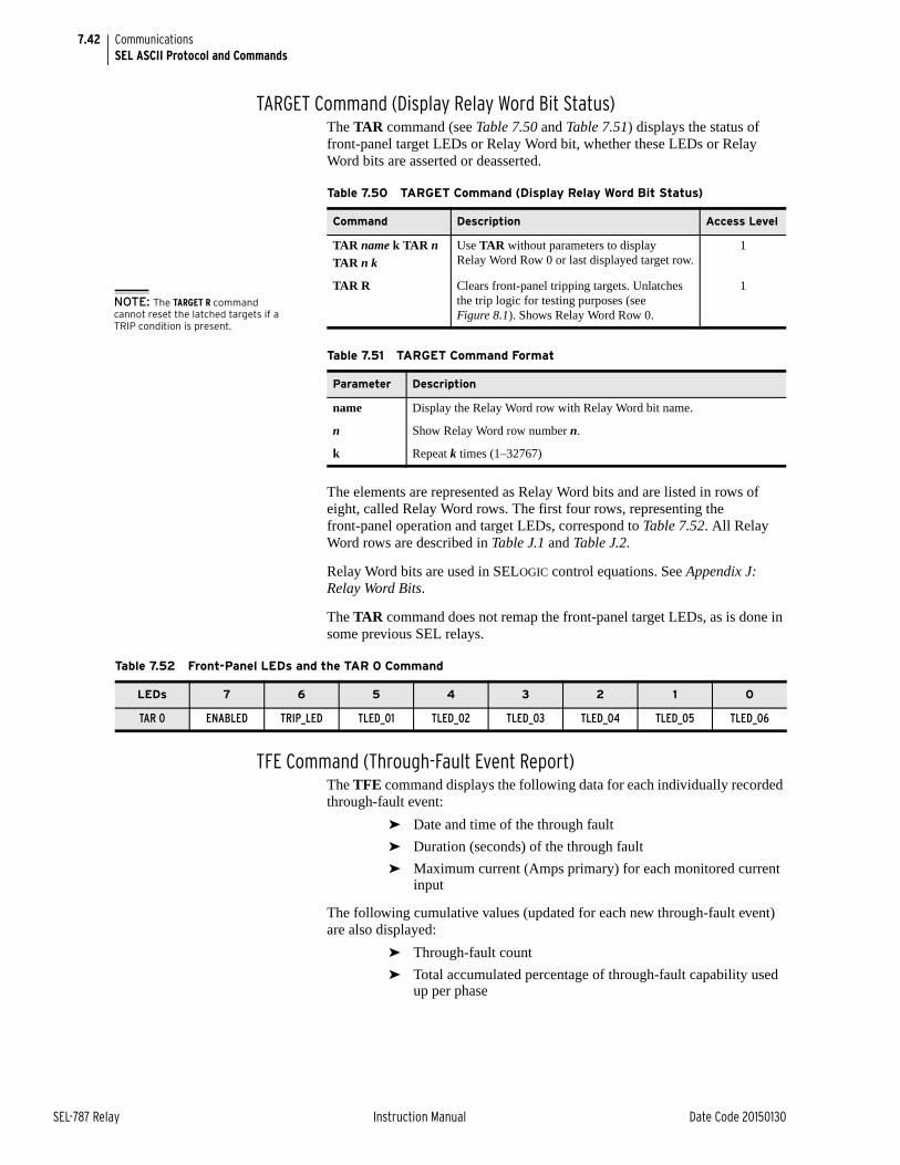
7.42
SEL-787 Relay Instruction Manual Date Code 20150130
CommunicationsSEL ASCII Protocol and Commands
TARGET Command (Display Relay Word Bit Status)The TAR command (see Table 7.50 and Table 7.51) displays the status of front-panel target LEDs or Relay Word bit, whether these LEDs or Relay Word bits are asserted or deasserted.
The elements are represented as Relay Word bits and are listed in rows of eight, called Relay Word rows. The first four rows, representing the front-panel operation and target LEDs, correspond to Table 7.52. All Relay Word rows are described in Table J.1 and Table J.2.
Relay Word bits are used in SELOGIC control equations. See Appendix J: Relay Word Bits.
The TAR command does not remap the front-panel target LEDs, as is done in some previous SEL relays.
TFE Command (Through-Fault Event Report)The TFE command displays the following data for each individually recorded through-fault event:
➤ Date and time of the through fault
➤ Duration (seconds) of the through fault
➤ Maximum current (Amps primary) for each monitored current input
The following cumulative values (updated for each new through-fault event) are also displayed:
➤ Through-fault count
➤ Total accumulated percentage of through-fault capability used up per phase
Table 7.50 TARGET Command (Display Relay Word Bit Status)
Command Description Access Level
TAR name k TAR nTAR n k
Use TAR without parameters to display Relay Word Row 0 or last displayed target row.
1
TAR R Clears front-panel tripping targets. Unlatches the trip logic for testing purposes (see Figure 8.1). Shows Relay Word Row 0.
1
Table 7.51 TARGET Command Format
Parameter Description
name Display the Relay Word row with Relay Word bit name.
n Show Relay Word row number n.
k Repeat k times (1–32767)
NOTE: The TARGET R command cannot reset the latched targets if a TRIP condition is present.
Table 7.52 Front-Panel LEDs and the TAR 0 Command
LEDs 7 6 5 4 3 2 1 0
TAR 0 ENABLED TRIP_LED TLED_01 TLED_02 TLED_03 TLED_04 TLED_05 TLED_06
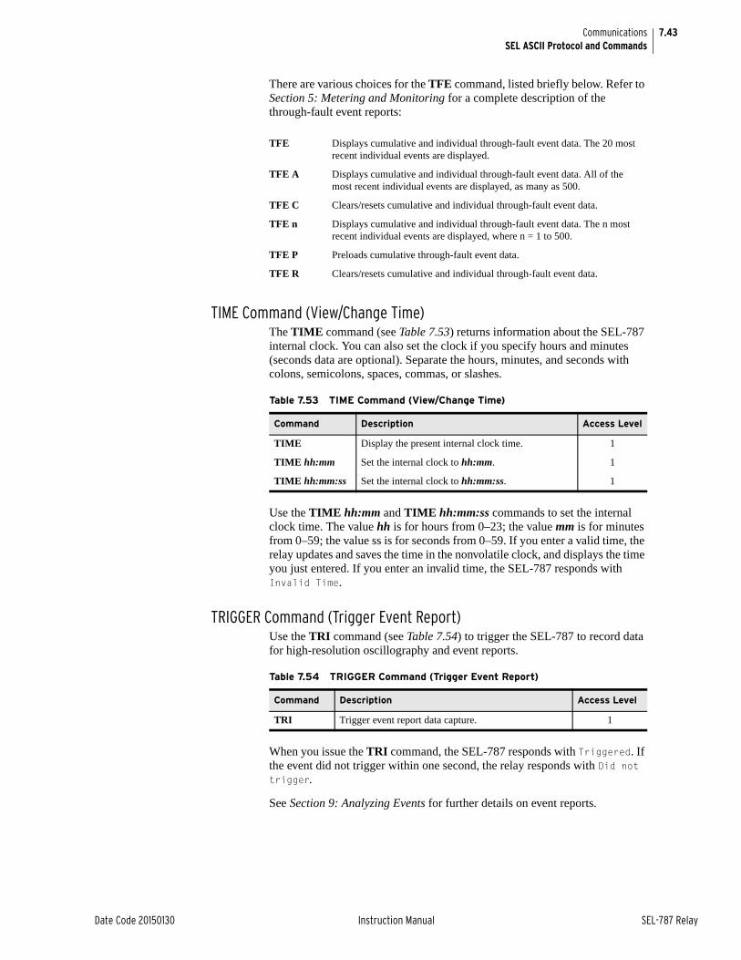
7.43
Date Code 20150130 Instruction Manual SEL-787 Relay
CommunicationsSEL ASCII Protocol and Commands
There are various choices for the TFE command, listed briefly below. Refer to Section 5: Metering and Monitoring for a complete description of the through-fault event reports:
TIME Command (View/Change Time)The TIME command (see Table 7.53) returns information about the SEL-787 internal clock. You can also set the clock if you specify hours and minutes (seconds data are optional). Separate the hours, minutes, and seconds with colons, semicolons, spaces, commas, or slashes.
Use the TIME hh:mm and TIME hh:mm:ss commands to set the internal clock time. The value hh is for hours from 0–23; the value mm is for minutes from 0–59; the value ss is for seconds from 0–59. If you enter a valid time, the relay updates and saves the time in the nonvolatile clock, and displays the time you just entered. If you enter an invalid time, the SEL-787 responds with Invalid Time.
TRIGGER Command (Trigger Event Report)Use the TRI command (see Table 7.54) to trigger the SEL-787 to record data for high-resolution oscillography and event reports.
When you issue the TRI command, the SEL-787 responds with Triggered. If the event did not trigger within one second, the relay responds with Did not trigger.
See Section 9: Analyzing Events for further details on event reports.
TFE Displays cumulative and individual through-fault event data. The 20 most recent individual events are displayed.
TFE A Displays cumulative and individual through-fault event data. All of the most recent individual events are displayed, as many as 500.
TFE C Clears/resets cumulative and individual through-fault event data.
TFE n Displays cumulative and individual through-fault event data. The n most recent individual events are displayed, where n = 1 to 500.
TFE P Preloads cumulative through-fault event data.
TFE R Clears/resets cumulative and individual through-fault event data.
Table 7.53 TIME Command (View/Change Time)
Command Description Access Level
TIME Display the present internal clock time. 1
TIME hh:mm Set the internal clock to hh:mm. 1
TIME hh:mm:ss Set the internal clock to hh:mm:ss. 1
Table 7.54 TRIGGER Command (Trigger Event Report)
Command Description Access Level
TRI Trigger event report data capture. 1
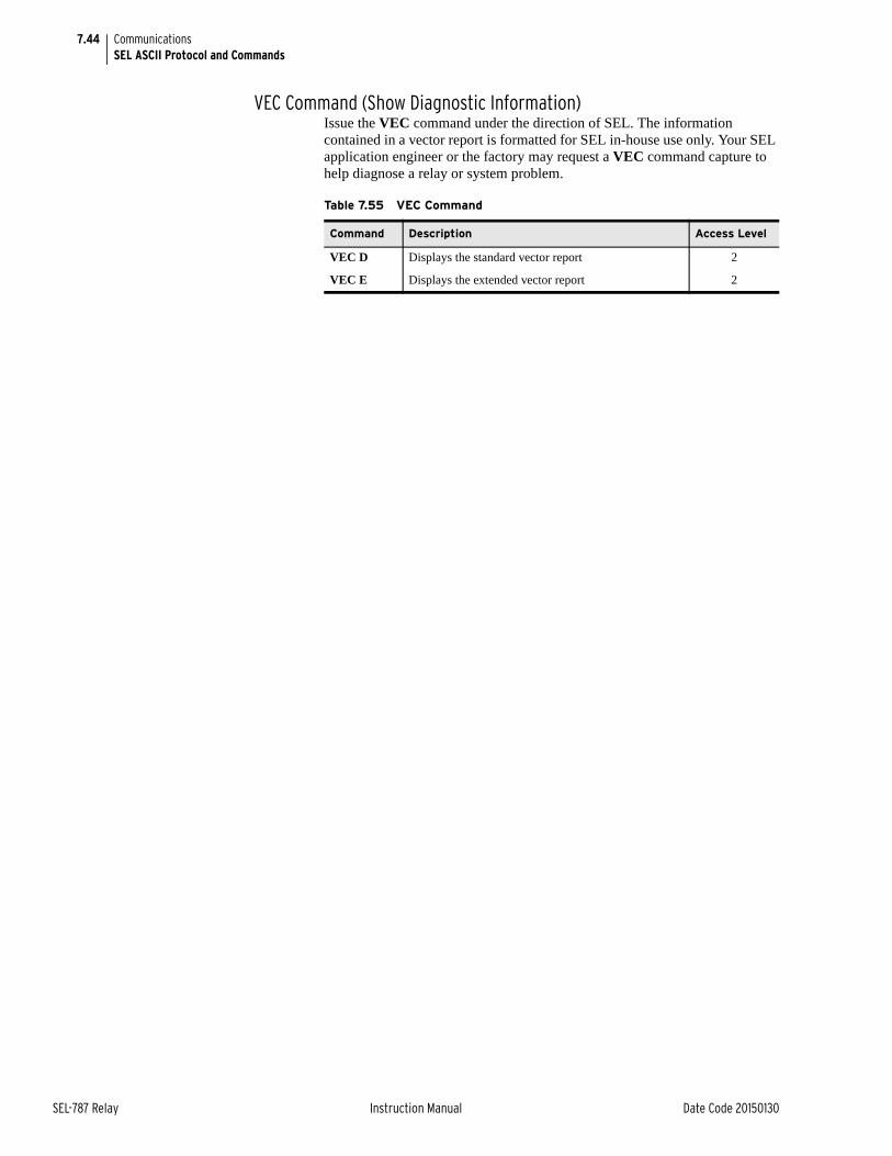
7.44
SEL-787 Relay Instruction Manual Date Code 20150130
CommunicationsSEL ASCII Protocol and Commands
VEC Command (Show Diagnostic Information)Issue the VEC command under the direction of SEL. The information contained in a vector report is formatted for SEL in-house use only. Your SEL application engineer or the factory may request a VEC command capture to help diagnose a relay or system problem.
Table 7.55 VEC Command
Command Description Access Level
VEC D Displays the standard vector report 2
VEC E Displays the extended vector report 2
Date Code 20150130 Instruction Manual SEL-787 Relay
Section 8Front-Panel Operations
Instruction Manual
OverviewThe SEL-787 Transformer Protection Relay front panel makes transformer data collection and control quick and efficient. Use the front panel to analyze operating information, view and change relay settings, and perform control functions. The SEL-787 features a straightforward menu-driven control structure presented on the front-panel liquid crystal display (LCD). Front-panel targets and other LEDs give a clear indication of the SEL-787 operation status. The features that help you operate the relay from the front panel include the following:
➤ Reading metering
➤ Inspecting targets
➤ Accessing settings
➤ Controlling relay operations
➤ Viewing diagnostics
Front-Panel LayoutFigure 8.1 shows and identifies the following regions:
➤ Human-Machine Interface (HMI)
➤ TARGET RESET and navigation pushbuttons
➤ Operation and target LEDs
➤ Operator control pushbuttons and pushbutton LEDs
➤ EIA-232 Serial Port (PORT F). See Section 7: Communications for details on the serial port.
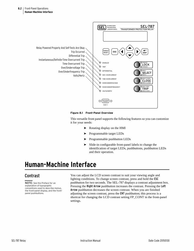
8.2
SEL-787 Relay Instruction Manual Date Code 20150130
Front-Panel OperationsHuman-Machine Interface
Figure 8.1 Front-Panel Overview
This versatile front panel supports the following features so you can customize it for your needs:
➤ Rotating display on the HMI
➤ Programmable target LEDs
➤ Programmable pushbutton LEDs
➤ Slide-in configurable front-panel labels to change the identification of target LEDs, pushbuttons, pushbutton LEDs and their operation.
Human-Machine Interface
Contrast You can adjust the LCD screen contrast to suit your viewing angle and lighting conditions. To change screen contrast, press and hold the ESC pushbutton for two seconds. The SEL-787 displays a contrast adjustment box. Pressing the Right Arrow pushbutton increases the contrast. Pressing the Left Arrow pushbutton decreases the screen contrast. When you are finished adjusting the screen contrast, press the ENT pushbutton; this process is a shortcut for changing the LCD contrast setting FP_CONT in the front-panel settings.
Relay Powered Properly And Self-Tests Are Okay
Trip Occurred
Differential Trip
Instantaneous/Definite-Time Overcurrent Trip
Time Overcurrent Trip
Over/Undervoltage Trip
Over/Underfrequency Trip
Volts/Hertz
ENABLED
LOCKDISABLED
BRKR 1
SELECTBRKR 2
BRKR 1 CLOSED
CLOSEBRKR 2 CLOSED
BRKR 1 OPEN
TRIPBRKR 2 OPEN
SEL-787TRANSFORMER PROTECTION RELAY
ENABLED
TRIP
DIFFERENTIAL
INST. OVERCURRENT
TIME OVERCURRENT
OVER/UNDERVOLTAGE
OVER/UNDERFREQUENCY
VOLTS/HERTZ
NOTE: See the Preface for an explanation of typographic conventions used to describe menus, the front-panel display, and the front-panel pushbuttons.
8.3
Date Code 20150130 Instruction Manual SEL-787 Relay
Front-Panel OperationsHuman-Machine Interface
Front-Panel Automatic Messages
The relay displays automatic messages, overriding the rotating display, under the conditions described in Table 8.1, with the relay failure having the highest priority, followed by trip and alarm when the front-panel setting FP_AUTO := OVERRIDE.
If the front-panel setting FP_AUTO := ROTATING, then the rotating display messages continue and any TRIP or ALARM message is added to the rotation. Relay failure will still override the rotating display.
Front-Panel SecurityFront-Panel Access Levels
The SEL-787 front panel typically operates at Access Level 1 and provides viewing of relay measurements and settings. Some activities, such as editing settings and controlling output contacts, are restricted to those operators who know the Access Level 2 passwords.
In the following figures, the padlock symbol indicates restricted activities.
Figure 8.2 Access Level Security Padlock Symbol
Before you can perform a front-panel menu activity that is marked with the padlock symbol, you must enter the correct Access Level 2 passwords. After you have correctly entered the password, you can perform other Access Level 2 activities without reentering the password.
Access Level 2 Password EntryWhen you try to perform an Access Level 2 activity, the relay determines whether you have entered the correct Access Level 2 password since the front-panel inactivity timer expired. If you have not, the relay displays the screen shown in Figure 8.3 for you to enter the password.
Table 8.1 Front-Panel Automatic Messages (FP_AUTO := OVERRIDE)
Condition Front-Panel Message
Relay detecting any failure Displays the type of latest failure (see Section 10: Testing and Troubleshooting).
Relay trip has occurred Displays the type or cause of the trip. Refer to Table 9.1 for a list of trip display messages.
Relay alarm condition has occurred
Displays the type of alarm. The TRIP LED is also flashing during an alarm condition.
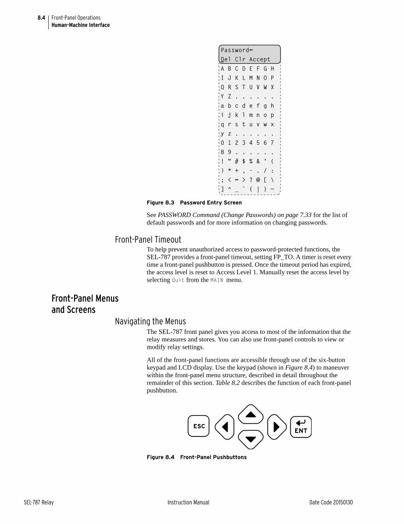
8.4
SEL-787 Relay Instruction Manual Date Code 20150130
Front-Panel OperationsHuman-Machine Interface
Figure 8.3 Password Entry Screen
See PASSWORD Command (Change Passwords) on page 7.33 for the list of default passwords and for more information on changing passwords.
Front-Panel TimeoutTo help prevent unauthorized access to password-protected functions, the SEL-787 provides a front-panel timeout, setting FP_TO. A timer is reset every time a front-panel pushbutton is pressed. Once the timeout period has expired, the access level is reset to Access Level 1. Manually reset the access level by selecting Quit from the MAIN menu.
Front-Panel Menus and Screens
Navigating the MenusThe SEL-787 front panel gives you access to most of the information that the relay measures and stores. You can also use front-panel controls to view or modify relay settings.
All of the front-panel functions are accessible through use of the six-button keypad and LCD display. Use the keypad (shown in Figure 8.4) to maneuver within the front-panel menu structure, described in detail throughout the remainder of this section. Table 8.2 describes the function of each front-panel pushbutton.
Figure 8.4 Front-Panel Pushbuttons
Password=Del Clr AcceptA B C D E F G HI J K L M N O PQ R S T U V W XY Z . . . . . .a b c d e f g hi j k l m n o pq r s t u v w xy z . . . . . .0 1 2 3 4 5 6 78 9 . . . . . .! " # $ % & ' () * + , - . / :; < = > ? @ [ \] ^ _ ` { | } ~
ESC
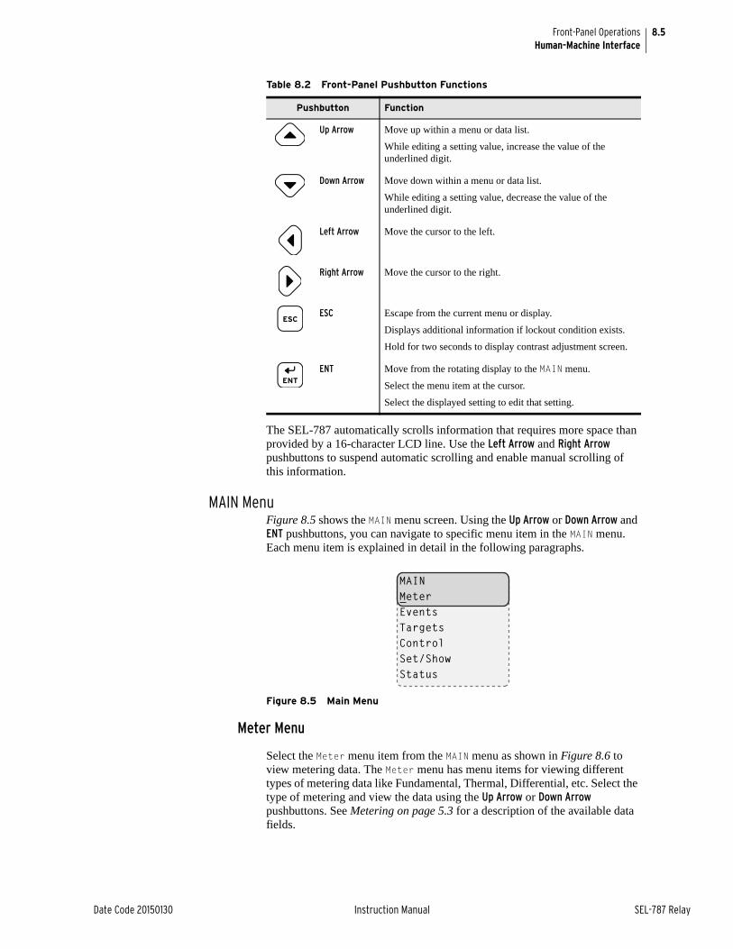
8.5
Date Code 20150130 Instruction Manual SEL-787 Relay
Front-Panel OperationsHuman-Machine Interface
The SEL-787 automatically scrolls information that requires more space than provided by a 16-character LCD line. Use the Left Arrow and Right Arrow pushbuttons to suspend automatic scrolling and enable manual scrolling of this information.
MAIN Menu Figure 8.5 shows the MAIN menu screen. Using the Up Arrow or Down Arrow and ENT pushbuttons, you can navigate to specific menu item in the MAIN menu. Each menu item is explained in detail in the following paragraphs.
Figure 8.5 Main Menu
Meter Menu
Select the Meter menu item from the MAIN menu as shown in Figure 8.6 to view metering data. The Meter menu has menu items for viewing different types of metering data like Fundamental, Thermal, Differential, etc. Select the type of metering and view the data using the Up Arrow or Down Arrow pushbuttons. See Metering on page 5.3 for a description of the available data fields.
Table 8.2 Front-Panel Pushbutton Functions
Pushbutton Function
Up Arrow Move up within a menu or data list.
While editing a setting value, increase the value of the underlined digit.
Down Arrow Move down within a menu or data list.
While editing a setting value, decrease the value of the underlined digit.
Left Arrow Move the cursor to the left.
Right Arrow Move the cursor to the right.
ESC Escape from the current menu or display.
Displays additional information if lockout condition exists.
Hold for two seconds to display contrast adjustment screen.
ENT Move from the rotating display to the MAIN menu.
Select the menu item at the cursor.
Select the displayed setting to edit that setting.
MAINMeterEventsTargetsControlSet/ShowStatus
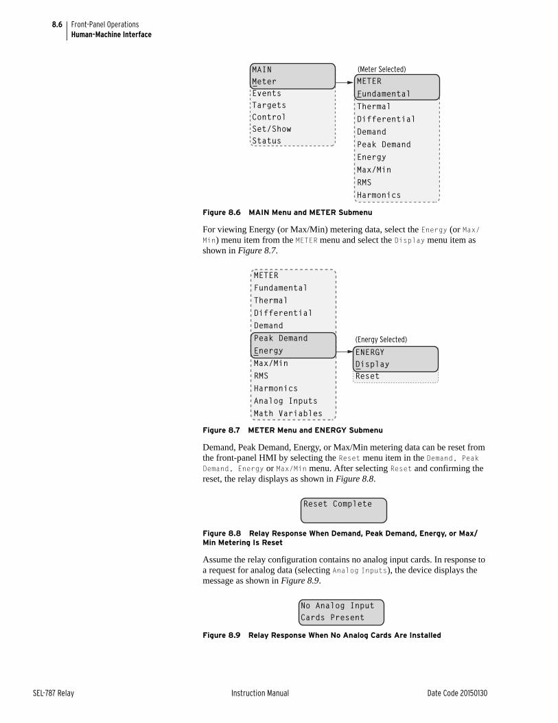
8.6
SEL-787 Relay Instruction Manual Date Code 20150130
Front-Panel OperationsHuman-Machine Interface
Figure 8.6 MAIN Menu and METER Submenu
For viewing Energy (or Max/Min) metering data, select the Energy (or Max/Min) menu item from the METER menu and select the Display menu item as shown in Figure 8.7.
Figure 8.7 METER Menu and ENERGY Submenu
Demand, Peak Demand, Energy, or Max/Min metering data can be reset from the front-panel HMI by selecting the Reset menu item in the Demand, Peak Demand, Energy or Max/Min menu. After selecting Reset and confirming the reset, the relay displays as shown in Figure 8.8.
Figure 8.8 Relay Response When Demand, Peak Demand, Energy, or Max/Min Metering Is Reset
Assume the relay configuration contains no analog input cards. In response to a request for analog data (selecting Analog Inputs), the device displays the message as shown in Figure 8.9.
Figure 8.9 Relay Response When No Analog Cards Are Installed
(Meter Selected)MAINMeterEventsTargetsControlSet/ShowStatus
METERFundamentalThermalDifferentialDemandPeak DemandEnergyMax/MinRMSHarmonics
(Energy Selected)
ENERGYDisplayReset
METERFundamentalThermalDifferentialDemandPeak DemandEnergyMax/MinRMSHarmonicsAnalog InputsMath Variables
Reset Complete
No Analog InputCards Present
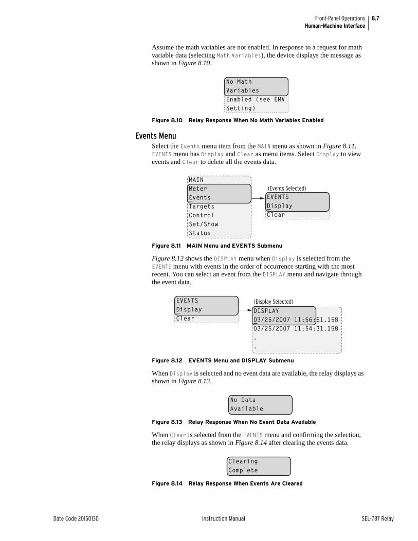
8.7
Date Code 20150130 Instruction Manual SEL-787 Relay
Front-Panel OperationsHuman-Machine Interface
Assume the math variables are not enabled. In response to a request for math variable data (selecting Math Variables), the device displays the message as shown in Figure 8.10.
Figure 8.10 Relay Response When No Math Variables Enabled
Events MenuSelect the Events menu item from the MAIN menu as shown in Figure 8.11. EVENTS menu has Display and Clear as menu items. Select Display to view events and Clear to delete all the events data.
Figure 8.11 MAIN Menu and EVENTS Submenu
Figure 8.12 shows the DISPLAY menu when Display is selected from the EVENTS menu with events in the order of occurrence starting with the most recent. You can select an event from the DISPLAY menu and navigate through the event data.
Figure 8.12 EVENTS Menu and DISPLAY Submenu
When Display is selected and no event data are available, the relay displays as shown in Figure 8.13.
Figure 8.13 Relay Response When No Event Data Available
When Clear is selected from the EVENTS menu and confirming the selection, the relay displays as shown in Figure 8.14 after clearing the events data.
Figure 8.14 Relay Response When Events Are Cleared
No MathVariablesEnabled (see EMV Setting)
MAINMeterEventsTargetsControlSet/ShowStatus
EVENTSDisplayClear
(Events Selected)
DISPLAY03/25/2007 11:56:51.15803/25/2007 11:54:31.158..
EVENTSDisplayClear
(Display Selected)
No DataAvailable
ClearingComplete
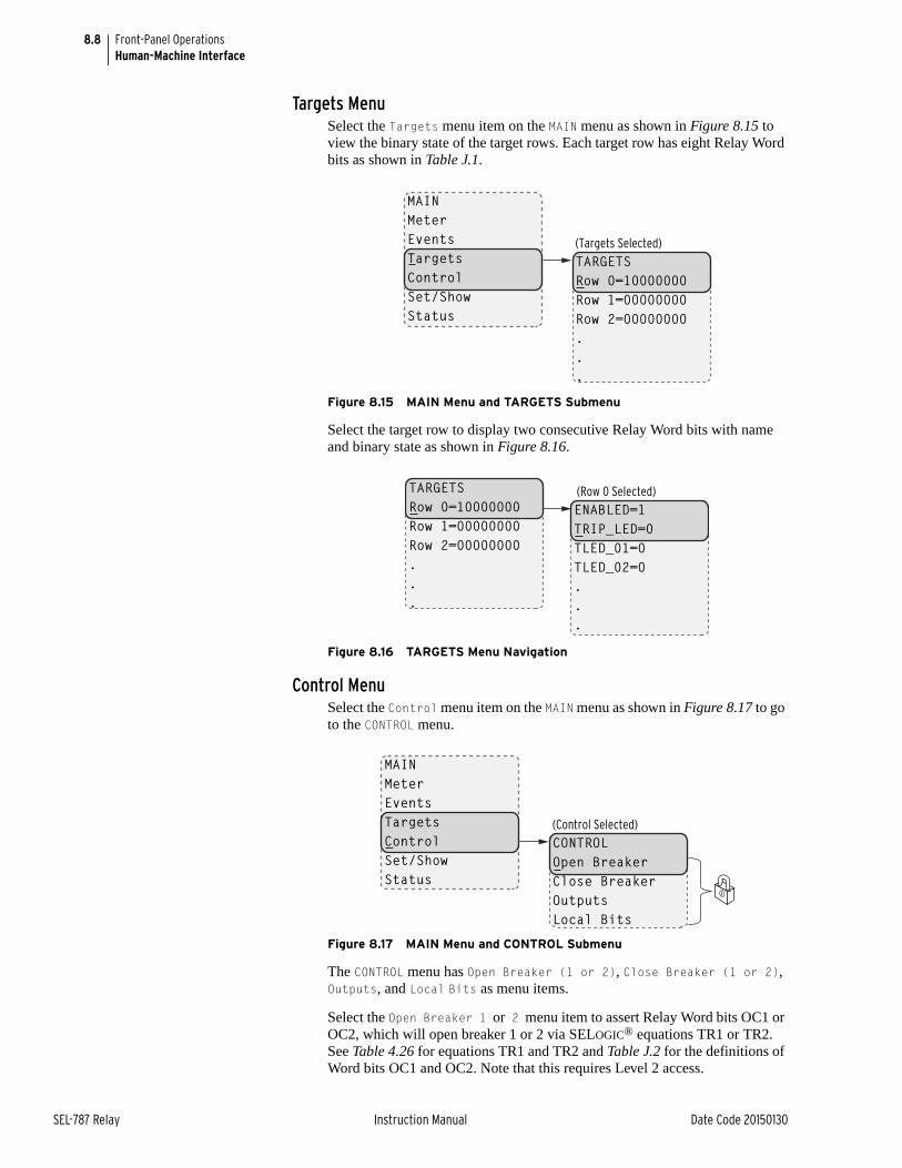
8.8
SEL-787 Relay Instruction Manual Date Code 20150130
Front-Panel OperationsHuman-Machine Interface
Targets MenuSelect the Targets menu item on the MAIN menu as shown in Figure 8.15 to view the binary state of the target rows. Each target row has eight Relay Word bits as shown in Table J.1.
Figure 8.15 MAIN Menu and TARGETS Submenu
Select the target row to display two consecutive Relay Word bits with name and binary state as shown in Figure 8.16.
Figure 8.16 TARGETS Menu Navigation
Control Menu Select the Control menu item on the MAIN menu as shown in Figure 8.17 to go to the CONTROL menu.
Figure 8.17 MAIN Menu and CONTROL Submenu
The CONTROL menu has Open Breaker (1 or 2), Close Breaker (1 or 2), Outputs, and Local Bits as menu items.
Select the Open Breaker 1 or 2 menu item to assert Relay Word bits OC1 or OC2, which will open breaker 1 or 2 via SELOGIC® equations TR1 or TR2. See Table 4.26 for equations TR1 and TR2 and Table J.2 for the definitions of Word bits OC1 and OC2. Note that this requires Level 2 access.
TARGETSRow 0=10000000Row 1=00000000Row 2=00000000...
(Targets Selected)
MAINMeterEventsTargetsControlSet/ShowStatus
TARGETSRow 0=10000000Row 1=00000000Row 2=00000000...
ENABLED=1TRIP_LED=0TLED_01=0TLED_02=0...
(Row 0 Selected)
CONTROLOpen BreakerClose BreakerOutputsLocal Bits
(Control Selected)
MAINMeterEventsTargetsControlSet/ShowStatus

8.9
Date Code 20150130 Instruction Manual SEL-787 Relay
Front-Panel OperationsHuman-Machine Interface
Select the Close Breaker 1 or 2 menu item to assert Relay Word bits CC1 or CC2, which will close the breaker 1 or 2 via the CL1 or CL2 SELOGIC equation (see Figure 4.51). Note that this requires Level 2 access.
Select the Outputs menu item from the CONTROL menu as shown in Figure 8.18 to test (pulse) SEL-787 output contacts and associated circuits. Choose the output contact by navigating through the OUTPUT menu and test it by pressing the ENT pushbutton. Note that testing the output contact requires Level 2 access and reconfirmation.
Figure 8.18 CONTROL Menu and OUTPUTS Submenu
Select the Local Bits menu item from the CONTROL menu for local control action. Local bits take the place of traditional panel switches, and perform isolation, open, close, or pulse operations.
With the settings as per the example in Section 4 (see Local Bits on page 4.105 for more information), local bit 1 replaces a supervisory switch. Figure 8.19 shows the screens in closing the supervisory switch. In this operation, local bit LB01 is deasserted (SUPER SW = OPEN), and changes to asserted (SUPER SW = CLOSE) as shown in the final screen of Figure 8.19.
Figure 8.19 CONTROL Menu and LOCAL BITS Submenu
CONTROLOpenCloseOutputsLocal Bits
OUTPUTSOUT101OUT102OUT103...
(Outputs Selected)
LOCAL BITSSUPERV SW = OPEN
SUPERV SW = OPENCLOSE
CLOSEYES No
SUPERV SW = CLOSEOPEN
CONTROLOpenCloseOutputsLocal Bits
(Local Bits Selected)
(SUPERV SW Selected)
(CLOSE Selected)
(Yes Selected)
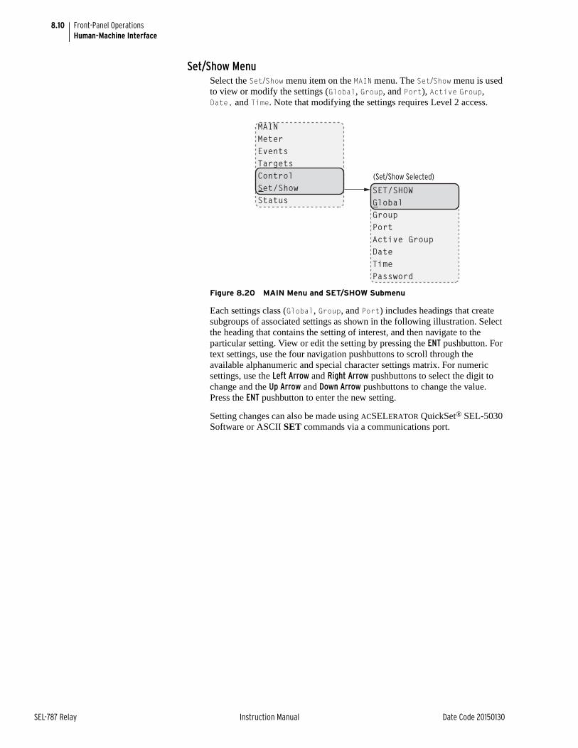
8.10
SEL-787 Relay Instruction Manual Date Code 20150130
Front-Panel OperationsHuman-Machine Interface
Set/Show MenuSelect the Set/Show menu item on the MAIN menu. The Set/Show menu is used to view or modify the settings (Global, Group, and Port), Active Group, Date, and Time. Note that modifying the settings requires Level 2 access.
Figure 8.20 MAIN Menu and SET/SHOW Submenu
Each settings class (Global, Group, and Port) includes headings that create subgroups of associated settings as shown in the following illustration. Select the heading that contains the setting of interest, and then navigate to the particular setting. View or edit the setting by pressing the ENT pushbutton. For text settings, use the four navigation pushbuttons to scroll through the available alphanumeric and special character settings matrix. For numeric settings, use the Left Arrow and Right Arrow pushbuttons to select the digit to change and the Up Arrow and Down Arrow pushbuttons to change the value. Press the ENT pushbutton to enter the new setting.
Setting changes can also be made using ACSELERATOR QuickSet® SEL-5030 Software or ASCII SET commands via a communications port.
MAINMeterEventsTargetsControlSet/ShowStatus
SET/SHOWGlobalGroupPortActive GroupDateTimePassword
(Set/Show Selected)

8.11
Date Code 20150130 Instruction Manual SEL-787 Relay
Front-Panel OperationsHuman-Machine Interface
p
Figure 8.21 SET/SHOW Menu
PORT F1234
SET/SHOWGlobalGroupPortActive GroupDateTimePassword
GLOBALGeneral SettingsGroup Selection•••Access Control
1ID SettingsConfig Settings. . .Trip/Close Logic
FProtocol SelectComm Settings
Active Group 1
Date 03/29/2008
Time 14:04:36
(F Selected)
(1 Selected)
(Time Selected)
Password1
(Password Selected)
(Date Selected)
(Active Selected)
(Port Selected)
(Group Selected)
(Global Selected)
GROUP1234
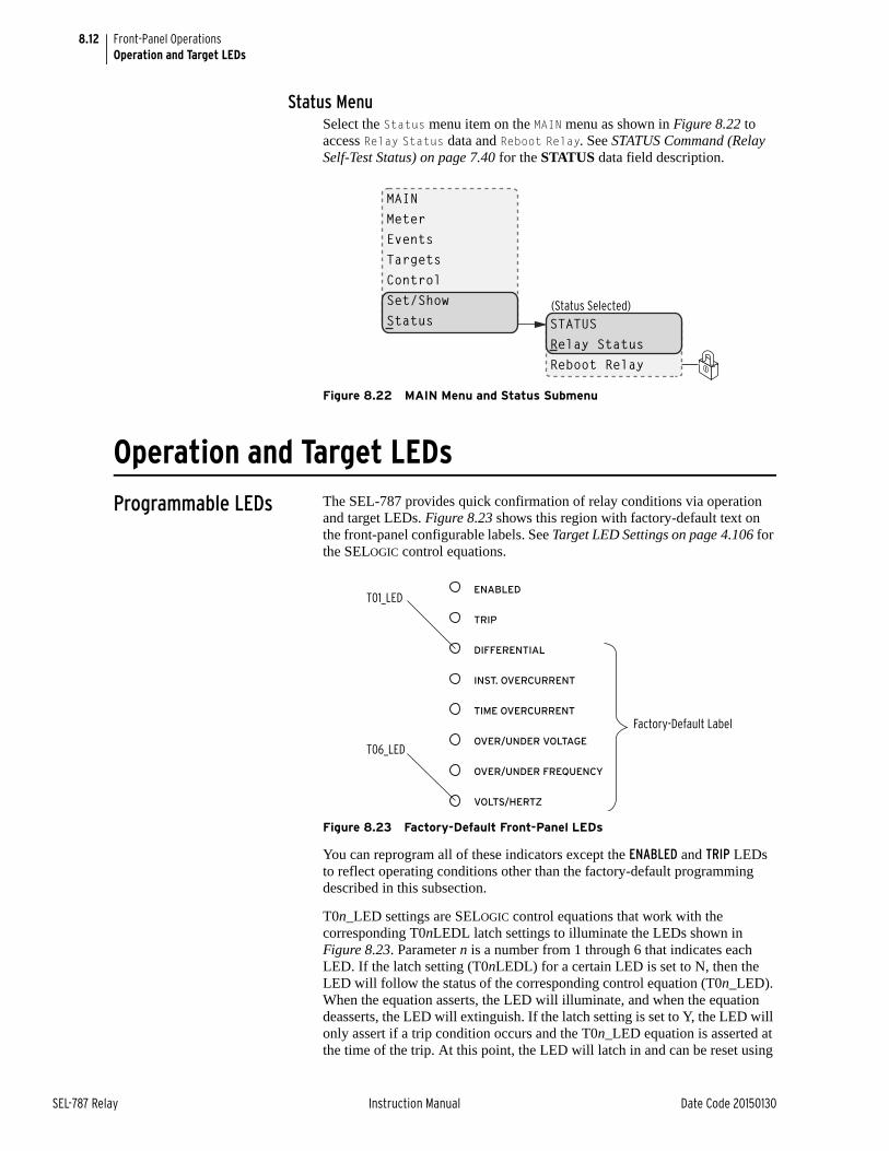
8.12
SEL-787 Relay Instruction Manual Date Code 20150130
Front-Panel OperationsOperation and Target LEDs
Status MenuSelect the Status menu item on the MAIN menu as shown in Figure 8.22 to access Relay Status data and Reboot Relay. See STATUS Command (Relay Self-Test Status) on page 7.40 for the STATUS data field description.
Figure 8.22 MAIN Menu and Status Submenu
Operation and Target LEDs
Programmable LEDs The SEL-787 provides quick confirmation of relay conditions via operation and target LEDs. Figure 8.23 shows this region with factory-default text on the front-panel configurable labels. See Target LED Settings on page 4.106 for the SELOGIC control equations.
Figure 8.23 Factory-Default Front-Panel LEDs
You can reprogram all of these indicators except the ENABLED and TRIP LEDs to reflect operating conditions other than the factory-default programming described in this subsection.
T0n_LED settings are SELOGIC control equations that work with the corresponding T0nLEDL latch settings to illuminate the LEDs shown in Figure 8.23. Parameter n is a number from 1 through 6 that indicates each LED. If the latch setting (T0nLEDL) for a certain LED is set to N, then the LED will follow the status of the corresponding control equation (T0n_LED). When the equation asserts, the LED will illuminate, and when the equation deasserts, the LED will extinguish. If the latch setting is set to Y, the LED will only assert if a trip condition occurs and the T0n_LED equation is asserted at the time of the trip. At this point, the LED will latch in and can be reset using
MAINMeterEventsTargetsControlSet/ShowStatus
(Status Selected)
STATUSRelay StatusReboot Relay
T01_LED
Factory-Default Label
T06_LED
ENABLED
TRIP
DIFFERENTIAL
INST. OVERCURRENT
TIME OVERCURRENT
OVER/UNDER VOLTAGE
OVER/UNDER FREQUENCY
VOLTS/HERTZ
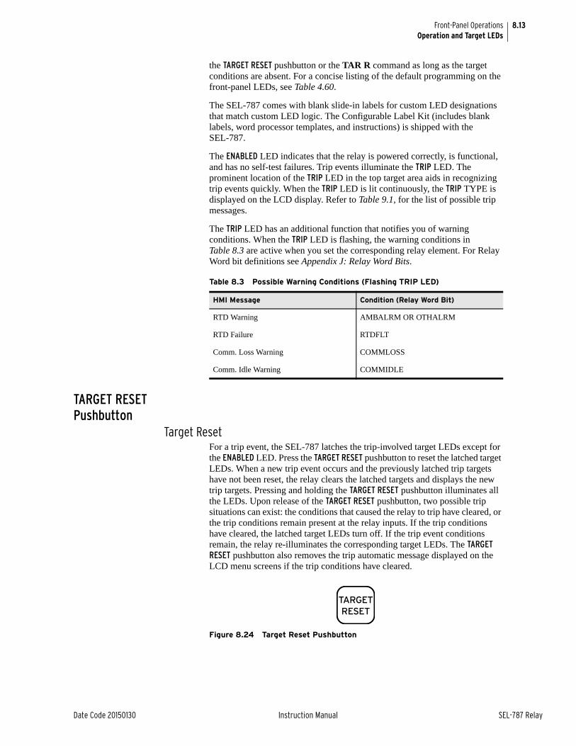
8.13
Date Code 20150130 Instruction Manual SEL-787 Relay
Front-Panel OperationsOperation and Target LEDs
the TARGET RESET pushbutton or the TAR R command as long as the target conditions are absent. For a concise listing of the default programming on the front-panel LEDs, see Table 4.60.
The SEL-787 comes with blank slide-in labels for custom LED designations that match custom LED logic. The Configurable Label Kit (includes blank labels, word processor templates, and instructions) is shipped with the SEL-787.
The ENABLED LED indicates that the relay is powered correctly, is functional, and has no self-test failures. Trip events illuminate the TRIP LED. The prominent location of the TRIP LED in the top target area aids in recognizing trip events quickly. When the TRIP LED is lit continuously, the TRIP TYPE is displayed on the LCD display. Refer to Table 9.1, for the list of possible trip messages.
The TRIP LED has an additional function that notifies you of warning conditions. When the TRIP LED is flashing, the warning conditions in Table 8.3 are active when you set the corresponding relay element. For Relay Word bit definitions see Appendix J: Relay Word Bits.
TARGET RESET Pushbutton
Target ResetFor a trip event, the SEL-787 latches the trip-involved target LEDs except for the ENABLED LED. Press the TARGET RESET pushbutton to reset the latched target LEDs. When a new trip event occurs and the previously latched trip targets have not been reset, the relay clears the latched targets and displays the new trip targets. Pressing and holding the TARGET RESET pushbutton illuminates all the LEDs. Upon release of the TARGET RESET pushbutton, two possible trip situations can exist: the conditions that caused the relay to trip have cleared, or the trip conditions remain present at the relay inputs. If the trip conditions have cleared, the latched target LEDs turn off. If the trip event conditions remain, the relay re-illuminates the corresponding target LEDs. The TARGET RESET pushbutton also removes the trip automatic message displayed on the LCD menu screens if the trip conditions have cleared.
Figure 8.24 Target Reset Pushbutton
Table 8.3 Possible Warning Conditions (Flashing TRIP LED)
HMI Message Condition (Relay Word Bit)
RTD Warning AMBALRM OR OTHALRM
RTD Failure RTDFLT
Comm. Loss Warning COMMLOSS
Comm. Idle Warning COMMIDLE
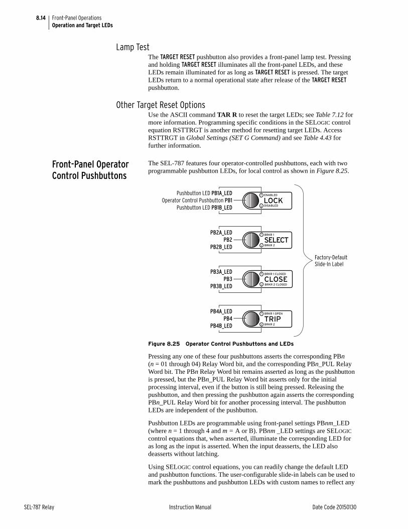
8.14
SEL-787 Relay Instruction Manual Date Code 20150130
Front-Panel OperationsOperation and Target LEDs
Lamp TestThe TARGET RESET pushbutton also provides a front-panel lamp test. Pressing and holding TARGET RESET illuminates all the front-panel LEDs, and these LEDs remain illuminated for as long as TARGET RESET is pressed. The target LEDs return to a normal operational state after release of the TARGET RESET pushbutton.
Other Target Reset OptionsUse the ASCII command TAR R to reset the target LEDs; see Table 7.12 for more information. Programming specific conditions in the SELOGIC control equation RSTTRGT is another method for resetting target LEDs. Access RSTTRGT in Global Settings (SET G Command) and see Table 4.43 for further information.
Front-Panel Operator Control Pushbuttons
The SEL-787 features four operator-controlled pushbuttons, each with two programmable pushbutton LEDs, for local control as shown in Figure 8.25.
Figure 8.25 Operator Control Pushbuttons and LEDs
Pressing any one of these four pushbuttons asserts the corresponding PBn (n = 01 through 04) Relay Word bit, and the corresponding PBn_PUL Relay Word bit. The PBn Relay Word bit remains asserted as long as the pushbutton is pressed, but the PBn_PUL Relay Word bit asserts only for the initial processing interval, even if the button is still being pressed. Releasing the pushbutton, and then pressing the pushbutton again asserts the corresponding PBn_PUL Relay Word bit for another processing interval. The pushbutton LEDs are independent of the pushbutton.
Pushbutton LEDs are programmable using front-panel settings PBnm_LED (where n = 1 through 4 and m = A or B). PBnm _LED settings are SELOGIC control equations that, when asserted, illuminate the corresponding LED for as long as the input is asserted. When the input deasserts, the LED also deasserts without latching.
Using SELOGIC control equations, you can readily change the default LED and pushbutton functions. The user-configurable slide-in labels can be used to mark the pushbuttons and pushbutton LEDs with custom names to reflect any
Factory-DefaultSlide-In Label
PB2A_LED
PB2
PB2B_LED
PB3A_LED
PB3
PB3B_LED
PB4A_LED
PB4
PB4B_LED
Pushbutton LED PB1A_LED
Operator Control Pushbutton PB1
Pushbutton LED PB1B_LED
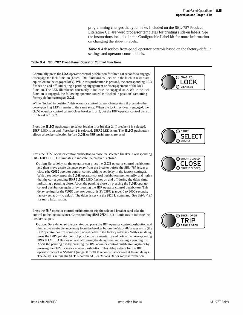
8.15
Date Code 20150130 Instruction Manual SEL-787 Relay
Front-Panel OperationsOperation and Target LEDs
programming changes that you make. Included on the SEL-787 Product Literature CD are word processor templates for printing slide-in labels. See the instructions included in the Configurable Label kit for more information on changing the slide-in labels.
Table 8.4 describes front-panel operator controls based on the factory-default settings and operator control labels.
Table 8.4 SEL-787 Front-Panel Operator Control Functions
Continually press the LOCK operator control pushbutton for three (3) seconds to engage/disengage the lock function (Latch LT01 functions as Lock with the latch in reset state equivalent to the engaged lock). While this pushbutton is pressed, the corresponding LED flashes on and off, indicating a pending engagement or disengagement of the lock function. The LED illuminates constantly to indicate the engaged state. While the lock function is engaged, the following operator control is “locked in position” (assuming factory-default settings): CLOSE.
While “locked in position,” this operator control cannot change state if pressed—the corresponding LEDs remain in the same state. When the lock function is engaged, the CLOSE operator control cannot close breaker 1 or 2, but the TRIP operator control can still trip breaker 1 or 2.
Press the SELECT pushbutton to select breaker 1 or breaker 2. If breaker 1 is selected, BRKR1 LED is on and if breaker 2 is selected, BRKR2 LED is on. The SELECT pushbutton allows a breaker selection before CLOSE or TRIP pushbuttons are used.
Press the CLOSE operator control pushbutton to close the selected breaker. Corresponding BRKR CLOSED LED illuminates to indicate the breaker is closed.
Option: Set a delay, so the operator can press the CLOSE operator control pushbutton and then move a safe distance away from the breaker before the SEL-787 issues a close (the CLOSE operator control comes with no set delay in the factory settings). With a set delay, press the CLOSE operator control pushbutton momentarily, and notice that the corresponding BRKR CLOSED LED flashes on and off during the delay time, indicating a pending close. Abort the pending close by pressing the CLOSE operator control pushbutton again or by pressing the TRIP operator control pushbutton. This delay setting for the CLOSE operator control is SV03PU (range: 0 to 3000 seconds; factory set at 0—no delay). The delay is set via the SET L command. See Table 4.31 for more information.
Press the TRIP operator control pushbutton to trip the selected breaker (and take the control to the lockout state). Corresponding BRKR OPEN LED illuminates to indicate the breaker is open.
Option: Set a delay, so the operator can press the TRIP operator control pushbutton and then move a safe distance away from the breaker before the SEL-787 issues a trip (the TRIP operator control comes with no set delay in the factory settings). With a set delay, press the TRIP operator control pushbutton momentarily and notice the corresponding BRKR OPEN LED flashes on and off during the delay time, indicating a pending trip. Abort the pending trip by pressing the TRIP operator control pushbutton again or by pressing the CLOSE operator control pushbutton. This delay setting for the TRIP operator control is SV04PU (range: 0 to 3000 seconds; factory-set at 0—no delay). The delay is set via the SET L command. See Table 4.31 for more information.
ENABLED
LOCKDISABLED
BRKR 1
SELECTBRKR 2
BRKR 1 CLOSED
CLOSEBRKR 2 CLOSED
BRKR 1 OPEN
TRIPBRKR 2 OPEN

This page intentionally left blank
Date Code 20150130 Instruction Manual SEL-787 Relay
Section 9Analyzing Events
Instruction Manual
OverviewThe SEL-787 Transformer Protection Relay provides several tools (listed below) to analyze the cause of relay operations. Use these tools to help diagnose the cause of the relay operation and more quickly restore the protected equipment to service.
➤ Event Reporting
➢ Event Summary Reports
➢ Event History Reports
➢ Event Reports
➤ Sequential Events Recorder Report
➢ Resolution: 1 ms
➢ Accuracy: ±1/4 cycle
All reports are stored in nonvolatile memory, ensuring that a loss of power to the SEL-787 will not result in lost data.
Event Reporting Analyze events with the following event reporting functions:
➤ Event Summaries—Enable automatic messaging to allow the relay to send event summaries out a serial port when port setting AUTO := Y. A summary provides a quick overview of an event. The summaries may also be retrieved by using the SUMMARY command.
➤ Event History—The relay keeps an index of stored nonvolatile event reports. Use the HISTORY command to obtain this index. The index includes some of the event summary information so that the appropriate event report can be identified and retrieved.
➤ Event Reports—These detailed reports are stored in nonvolatile memory for later retrieval and detailed analysis.
Each time an event occurs, a new summary, history record, and report are created. Event report information includes:
➤ Date and time of the event
➤ Individual sample analog inputs (currents and voltages)
➤ Digital states of selected Relay Word bits (listed in Table J.1)
➤ Event summary, including the front-panel target states at the time of tripping and fault type
➤ Group, Logic, Global, and Report settings (that were in service when the event was retrieved)
9.2
SEL-787 Relay Instruction Manual Date Code 20150130
Analyzing EventsEvent Reporting
The SEL-787 provides Compressed ASCII event reports to facilitate event report storage and display. SEL communications processors and the SEL-5601 Analytic Assistant software take advantage of the Compressed ASCII format. Use the CHIS command to display Compressed ASCII event history information. Use the CSUM command to display Compressed ASCII event summary information. Use the CEVENT command to display Compressed ASCII event reports. See Table C.2 for further information.
Compressed ASCII Event Reports contain all of the Relay Word bits.
Sequential Events Recorder (SER)
The SER report captures digital element state changes over time. Settings allow as many as 96 Relay Word bits to be monitored, in addition to the automatically generated triggers for relay power up, settings changes, and active setting group changes. State changes are time-tagged to the nearest millisecond. SER information is stored when state changes occur.
SER report data are useful in commissioning tests and during operation for system monitoring and control.
Event ReportingLength The SEL-787 provides selectable event report length (LER) and prefault
length (PRE). Event report length is either 15 or 64 cycles. Prefault length is 1–10 cycles for LER = 15 and 1–59 cycles for LER = 64. Prefault length is the first part of the total event report length and precedes the event report triggering point. Changing the PRE setting has no effect on the stored reports. The relay stores as many as 19 of the most recent 64-cycle or as many as 77 of the most recent 15-cycle event reports in nonvolatile memory. Refer to the SET R command in SET Command (Change Settings) on page 7.36 and Report Settings (SET R Command) on page SET.52.
Triggering The SEL-787 triggers (generates) an event report when any of the following occur:
➤ Relay Word bit TRIP asserts
➤ Programmable SELOGIC® control equation setting ER asserts (in Report settings)
➤ TRI (Trigger Event Reports) serial port command executes
Relay Word Bit TRIPRefer to Figure 4.50. If Relay Word bit TR asserts to logical 1, an event report is automatically generated. Thus, any Relay Word bit that causes a trip does not have to be entered in SELOGIC control equation setting ER.
Programmable SELOGIC Control Equation Setting ERThe programmable SELOGIC control equation event report trigger setting ER is set to trigger event reports for conditions other than trip conditions (see SET R in SET Command (Change Settings) on page 7.36). When setting ER detects a logical 0 to logical 1 transition, it generates an event report (if the SEL-787 is not already generating a report that encompasses the new transition). The factory setting is shown in Event Report Settings on page 4.110.
IMPORTANT: Changing the LER setting will clear all events in memory. Be sure to save critical event data prior to changing the LER setting.
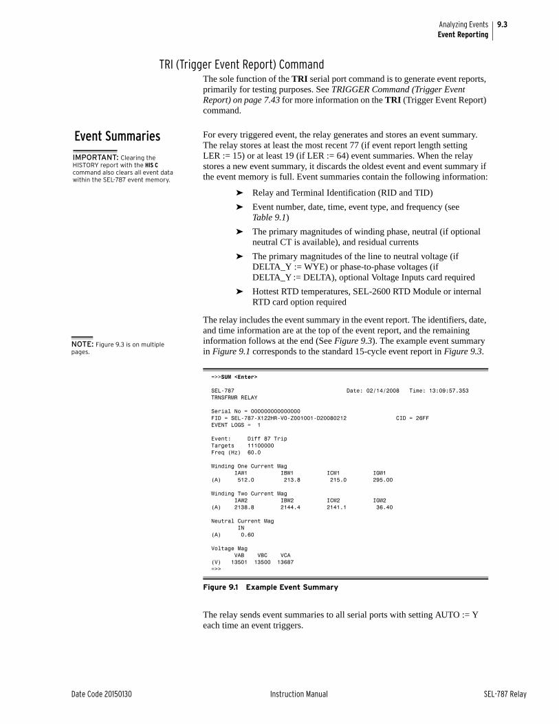
9.3
Date Code 20150130 Instruction Manual SEL-787 Relay
Analyzing EventsEvent Reporting
TRI (Trigger Event Report) CommandThe sole function of the TRI serial port command is to generate event reports, primarily for testing purposes. See TRIGGER Command (Trigger Event Report) on page 7.43 for more information on the TRI (Trigger Event Report) command.
Event Summaries For every triggered event, the relay generates and stores an event summary. The relay stores at least the most recent 77 (if event report length setting LER := 15) or at least 19 (if LER := 64) event summaries. When the relay stores a new event summary, it discards the oldest event and event summary if the event memory is full. Event summaries contain the following information:
➤ Relay and Terminal Identification (RID and TID)
➤ Event number, date, time, event type, and frequency (see Table 9.1)
➤ The primary magnitudes of winding phase, neutral (if optional neutral CT is available), and residual currents
➤ The primary magnitudes of the line to neutral voltage (if DELTA_Y := WYE) or phase-to-phase voltages (if DELTA_Y := DELTA), optional Voltage Inputs card required
➤ Hottest RTD temperatures, SEL-2600 RTD Module or internal RTD card option required
The relay includes the event summary in the event report. The identifiers, date, and time information are at the top of the event report, and the remaining information follows at the end (See Figure 9.3). The example event summary in Figure 9.1 corresponds to the standard 15-cycle event report in Figure 9.3.
The relay sends event summaries to all serial ports with setting AUTO := Y each time an event triggers.
=>>SUM <Enter>
SEL-787 Date: 02/14/2008 Time: 13:09:57.353TRNSFRMR RELAY
Serial No = 000000000000000FID = SEL-787-X122HR-V0-Z001001-D20080212 CID = 26FFEVENT LOGS = 1
Event: Diff 87 TripTargets 11100000Freq (Hz) 60.0
Winding One Current Mag IAW1 IBW1 ICW1 IGW1(A) 512.0 213.8 215.0 295.00
Winding Two Current Mag IAW2 IBW2 ICW2 IGW2(A) 2138.8 2144.4 2141.1 36.40
Neutral Current Mag IN(A) 0.60
Voltage Mag VAB VBC VCA(V) 13501 13500 13687=>>
Figure 9.1 Example Event Summary
IMPORTANT: Clearing the HISTORY report with the HIS C command also clears all event data within the SEL-787 event memory.
NOTE: Figure 9.3 is on multiple pages.
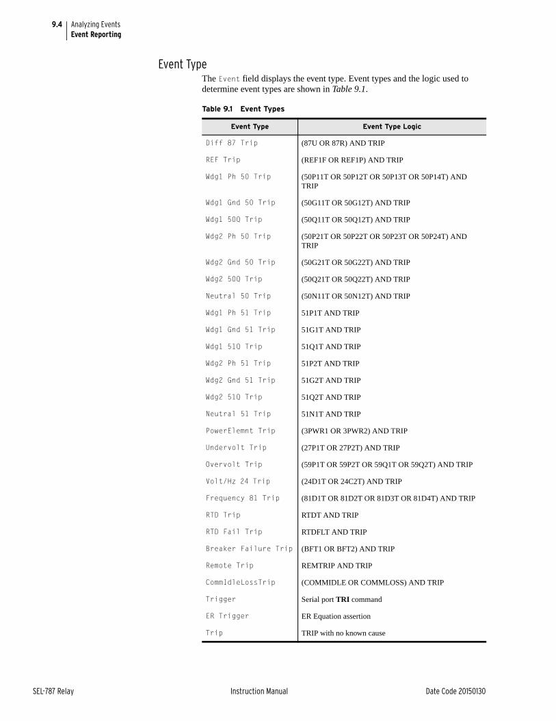
9.4
SEL-787 Relay Instruction Manual Date Code 20150130
Analyzing EventsEvent Reporting
Event TypeThe Event field displays the event type. Event types and the logic used to determine event types are shown in Table 9.1.
Table 9.1 Event Types
Event Type Event Type Logic
Diff 87 Trip (87U OR 87R) AND TRIP
REF Trip (REF1F OR REF1P) AND TRIP
Wdg1 Ph 50 Trip (50P11T OR 50P12T OR 50P13T OR 50P14T) AND TRIP
Wdg1 Gnd 50 Trip (50G11T OR 50G12T) AND TRIP
Wdg1 50Q Trip (50Q11T OR 50Q12T) AND TRIP
Wdg2 Ph 50 Trip (50P21T OR 50P22T OR 50P23T OR 50P24T) AND TRIP
Wdg2 Gnd 50 Trip (50G21T OR 50G22T) AND TRIP
Wdg2 50Q Trip (50Q21T OR 50Q22T) AND TRIP
Neutral 50 Trip (50N11T OR 50N12T) AND TRIP
Wdg1 Ph 51 Trip 51P1T AND TRIP
Wdg1 Gnd 51 Trip 51G1T AND TRIP
Wdg1 51Q Trip 51Q1T AND TRIP
Wdg2 Ph 51 Trip 51P2T AND TRIP
Wdg2 Gnd 51 Trip 51G2T AND TRIP
Wdg2 51Q Trip 51Q2T AND TRIP
Neutral 51 Trip 51N1T AND TRIP
PowerElemnt Trip (3PWR1 OR 3PWR2) AND TRIP
Undervolt Trip (27P1T OR 27P2T) AND TRIP
Overvolt Trip (59P1T OR 59P2T OR 59Q1T OR 59Q2T) AND TRIP
Volt/Hz 24 Trip (24D1T OR 24C2T) AND TRIP
Frequency 81 Trip (81D1T OR 81D2T OR 81D3T OR 81D4T) AND TRIP
RTD Trip RTDT AND TRIP
RTD Fail Trip RTDFLT AND TRIP
Breaker Failure Trip (BFT1 OR BFT2) AND TRIP
Remote Trip REMTRIP AND TRIP
CommIdleLossTrip (COMMIDLE OR COMMLOSS) AND TRIP
Trigger Serial port TRI command
ER Trigger ER Equation assertion
Trip TRIP with no known cause
9.5
Date Code 20150130 Instruction Manual SEL-787 Relay
Analyzing EventsEvent Reporting
Currents, Voltages, and RTD TemperaturesThe relay determines the maximum winding current during an event. The instant the maximum winding current occurs is marked by an asterisk (*) in the event report (see Figure 9.3). This row of data corresponds to the analogs shown in the summary report for the event.
The Current Mag fields display the primary current magnitudes at the instant when the maximum winding current was measured. The currents displayed are listed below:
➤ Winding Currents (IAWn, IBWn, ICWn, IGWn {n = 1 and 2})
➤ Neutral Current (IN)
The Voltage Mag fields display the primary voltage magnitudes at the instant when the maximum winding current was measured. The voltages displayed are listed below:
➤ DELTA_Y := WYE
➢ Phase-to-Neutral Voltages (VAN, VBN, VCN)
➢ Residual Voltage VG, calculated from VAN, VBN, VCN
➤ DELTA_Y := DELTA
➢ Phase-to-Phase Voltages (VAB, VBC, VCA)
If the RTDs are connected, the hottest RTD (°C) fields display the hottest RTD reading in each RTD group. The hottest RTD temperatures in degrees centigrade (°C) are listed below:
➤ Ambient
➤ Other
Event History The event history report gives you a quick look at recent relay activity. The relay labels each new event in reverse chronological order with 1 as the most recent event. See Figure 9.2 for a sample event history. Use this report to view the events that are presently stored in the SEL-787.
The event history contains the following:
➤ Standard report header
➢ Relay and terminal identification
➢ Date and time of report
➢ Time source (Internal or IRIG-B)
➤ Event number, date, time, event type (see Table 9.1)
➤ Maximum current
➤ Frequency (actual frequency if voltage card is available otherwise the nominal frequency)
➤ Target LED status
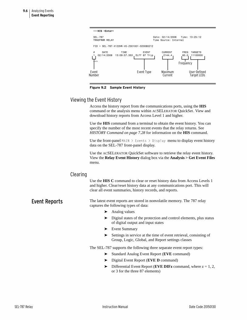
9.6
SEL-787 Relay Instruction Manual Date Code 20150130
Analyzing EventsEvent Reporting
Viewing the Event HistoryAccess the history report from the communications ports, using the HIS command or the analysis menu within ACSELERATOR QuickSet. View and download history reports from Access Level 1 and higher.
Use the HIS command from a terminal to obtain the event history. You can specify the number of the most recent events that the relay returns. See HISTORY Command on page 7.28 for information on the HIS command.
Use the front-panel MAIN > Events > Display menu to display event history data on the SEL-787 front-panel display.
Use the ACSELERATOR QuickSet software to retrieve the relay event history. View the Relay Event History dialog box via the Analysis > Get Event Files menu.
ClearingUse the HIS C command to clear or reset history data from Access Levels 1 and higher. Clear/reset history data at any communications port. This will clear all event summaries, history records, and reports.
Event Reports The latest event reports are stored in nonvolatile memory. The 787 relay captures the following types of data:
➤ Analog values
➤ Digital states of the protection and control elements, plus status of digital output and input states
➤ Event Summary
➤ Settings in service at the time of event retrieval, consisting of Group, Logic, Global, and Report settings classes
The SEL-787 supports the following three separate event report types:
➤ Standard Analog Event Report (EVE command)
➤ Digital Event Report (EVE D command)
➤ Differential Event Report (EVE DIFz command, where z = 1, 2, or 3 for the three 87 elements)
=>>HIS <Enter>
SEL-787 Date: 02/14/2008 Time: 13:25:12TRNSFRMR RELAY Time Source: Internal
FID = SEL-787-X122HR-V0-Z001001-D20080212
# DATE TIME EVENT CURRENT FREQ TARGETS1 02/14/2008 13:09:57.353 Diff 87 Trip 2144.4 60.0 11100000
=>>
Figure 9.2 Sample Event History
Event Number
Event Type Maximum Current
Frequency
User-Defined Target LEDs
9.7
Date Code 20150130 Instruction Manual SEL-787 Relay
Analyzing EventsEvent Reporting
Analog Event Reports (EVE Command)The Analog Event Report includes:
➤ Analog values of Winding 1 and 2 currents; IAW, IBW, ICW, IGW, (IGW only if voltage card is not used), neutral current IN (if available), voltages and frequency (if voltage card is used)
➤ Digital states of the base model digital inputs (2) and digital outputs (3)
➤ Event Summary
➤ Relay Settings
If the winding phase CTs are delta connected, the primary currents displayed are derived from the secondary values by multiplying them with CTR (CT ratio) and dividing them by the square root of 3. The phase angles shown are the same as the secondary values. If the CT connection type is known (DAB or DAC), the user can correct the phase angles. The MET response is meant to show steady-state primary values. During unbalanced conditions the primary line currents cannot be reproduced accurately because the delta-connected CTs filter out the zero-sequence component of the line current. Wye-connected CTs do not have any such issue.
Filtered and Unfiltered Analog Event ReportsThe SEL-787 samples the power system measurands (ac voltage and ac current) 16 times per power system cycle. A digital filter extracts the fundamental frequency component of the measurands. The relay operates on the filtered values and reports these values in the standard, filtered event report.
To view the raw inputs to the relay, select the unfiltered event report using the EVE R command. Use the unfiltered event reports to observe power system conditions:
➤ Power system transients on current and voltage channels
➤ Decaying dc offset during fault conditions on current channels
Raw event reports display one extra cycle of data at the beginning of the report.
Also, unlike the filtered report, the raw event report shows the actual relay terminal voltage inputs so if the external connections are for DELTA input, VA = Vab, VB = 0, VC = –Vbc (in primary volts).
Analog Event Report Column DefinitionsRefer to the example analog event report in Figure 9.3 to view event report columns. This example event report displays rows of information each 1/4 cycle. Retrieve this report with the EVE command.
The columns contain analog values, including ac current, ac voltage, and frequency, followed by base model input and output information.
NOTE: Figure 9.3 is on multiple pages.
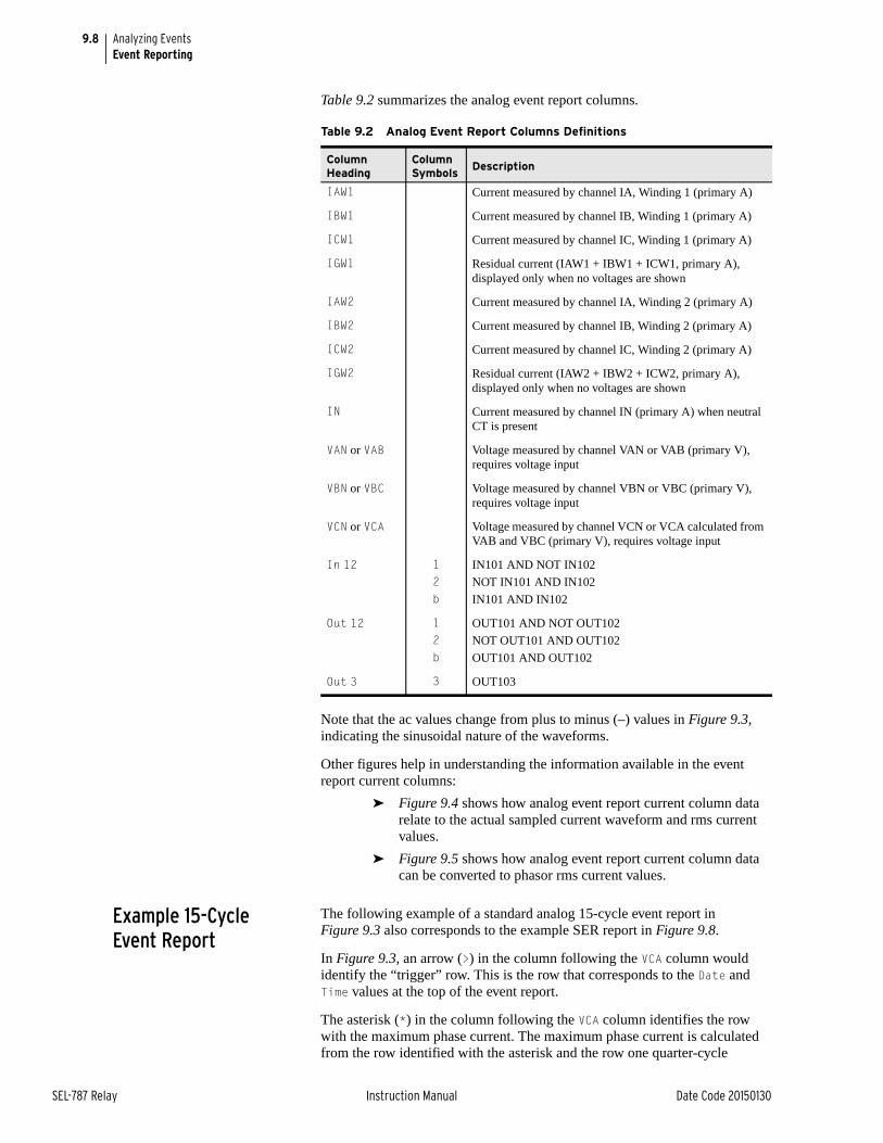
9.8
SEL-787 Relay Instruction Manual Date Code 20150130
Analyzing EventsEvent Reporting
Table 9.2 summarizes the analog event report columns.
Note that the ac values change from plus to minus (–) values in Figure 9.3, indicating the sinusoidal nature of the waveforms.
Other figures help in understanding the information available in the event report current columns:
➤ Figure 9.4 shows how analog event report current column data relate to the actual sampled current waveform and rms current values.
➤ Figure 9.5 shows how analog event report current column data can be converted to phasor rms current values.
Example 15-Cycle Event Report
The following example of a standard analog 15-cycle event report in Figure 9.3 also corresponds to the example SER report in Figure 9.8.
In Figure 9.3, an arrow (>) in the column following the VCA column would identify the “trigger” row. This is the row that corresponds to the Date and Time values at the top of the event report.
The asterisk (*) in the column following the VCA column identifies the row with the maximum phase current. The maximum phase current is calculated from the row identified with the asterisk and the row one quarter-cycle
Table 9.2 Analog Event Report Columns Definitions
Column Heading
Column Symbols
Description
IAW1 Current measured by channel IA, Winding 1 (primary A)
IBW1 Current measured by channel IB, Winding 1 (primary A)
ICW1 Current measured by channel IC, Winding 1 (primary A)
IGW1 Residual current (IAW1 + IBW1 + ICW1, primary A), displayed only when no voltages are shown
IAW2 Current measured by channel IA, Winding 2 (primary A)
IBW2 Current measured by channel IB, Winding 2 (primary A)
ICW2 Current measured by channel IC, Winding 2 (primary A)
IGW2 Residual current (IAW2 + IBW2 + ICW2, primary A), displayed only when no voltages are shown
IN Current measured by channel IN (primary A) when neutral CT is present
VAN or VAB Voltage measured by channel VAN or VAB (primary V), requires voltage input
VBN or VBC Voltage measured by channel VBN or VBC (primary V), requires voltage input
VCN or VCA Voltage measured by channel VCN or VCA calculated from VAB and VBC (primary V), requires voltage input
In 12 12b
IN101 AND NOT IN102
NOT IN101 AND IN102
IN101 AND IN102
Out 12 12b
OUT101 AND NOT OUT102
NOT OUT101 AND OUT102
OUT101 AND OUT102
Out 3 3 OUT103
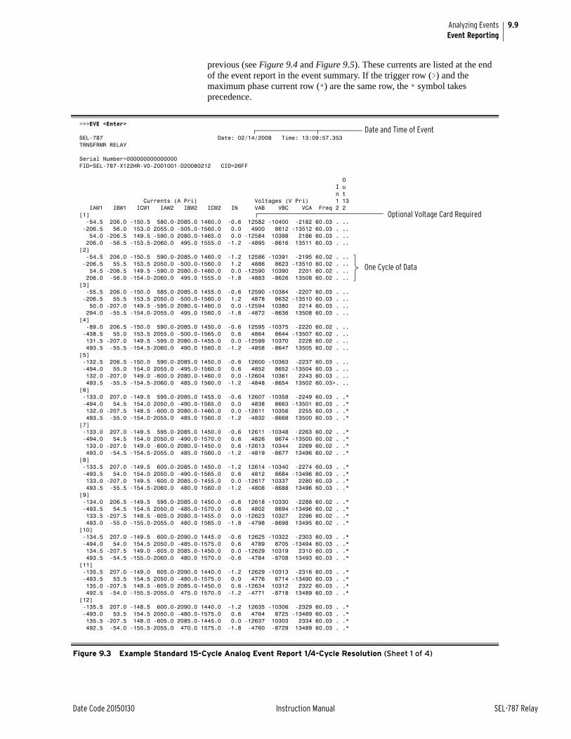
9.9
Date Code 20150130 Instruction Manual SEL-787 Relay
Analyzing EventsEvent Reporting
previous (see Figure 9.4 and Figure 9.5). These currents are listed at the end of the event report in the event summary. If the trigger row (>) and the maximum phase current row (*) are the same row, the * symbol takes precedence.
=>>EVE <Enter>
SEL-787 Date: 02/14/2008 Time: 13:09:57.353TRNSFRMR RELAY
Serial Number=000000000000000FID=SEL-787-X122HR-V0-Z001001-D20080212 CID=26FF
O I u n t Currents (A Pri) Voltages (V Pri) 1 13 IAW1 IBW1 ICW1 IAW2 IBW2 ICW2 IN VAB VBC VCA Freq 2 2 [1] -54.5 206.0 -150.5 580.0-2085.0 1460.0 -0.6 12582 -10400 -2182 60.03 . .. -206.5 56.0 153.0 2055.0 -505.0-1560.0 0.0 4900 8612 -13512 60.03 . .. 54.0 -206.5 149.5 -590.0 2080.0-1465.0 0.0 -12584 10398 2186 60.03 . .. 206.0 -56.5 -153.5-2060.0 495.0 1555.0 -1.2 -4895 -8616 13511 60.03 . ..[2] -54.5 206.0 -150.5 590.0-2085.0 1460.0 -1.2 12586 -10391 -2195 60.02 . .. -206.5 55.5 153.5 2050.0 -500.0-1560.0 1.2 4886 8623 -13510 60.02 . .. 54.5 -206.5 149.5 -590.0 2080.0-1460.0 0.0 -12590 10390 2201 60.02 . .. 206.0 -56.0 -154.0-2060.0 495.0 1555.0 -1.8 -4883 -8626 13508 60.02 . ..[3] -55.5 206.0 -150.0 585.0-2085.0 1455.0 -0.6 12590 -10384 -2207 60.03 . .. -206.5 55.5 153.5 2050.0 -500.0-1560.0 1.2 4878 8632 -13510 60.03 . .. 50.0 -207.0 149.5 -595.0 2080.0-1460.0 0.0 -12594 10380 2214 60.03 . .. 294.0 -55.5 -154.0-2055.0 495.0 1560.0 -1.8 -4872 -8636 13508 60.03 . ..[4] -89.0 206.5 -150.0 590.0-2085.0 1450.0 -0.6 12595 -10375 -2220 60.02 . .. -438.5 55.0 153.5 2055.0 -500.0-1565.0 0.6 4864 8644 -13507 60.02 . .. 131.5 -207.0 149.5 -595.0 2080.0-1455.0 0.0 -12599 10370 2228 60.02 . .. 493.5 -55.5 -154.5-2060.0 490.0 1560.0 -1.2 -4858 -8647 13505 60.02 . ..[5] -132.5 206.5 -150.0 590.0-2085.0 1450.0 -0.6 12600 -10363 -2237 60.03 . .. -494.0 55.0 154.0 2055.0 -495.0-1560.0 0.6 4852 8652 -13504 60.03 . .. 132.0 -207.0 149.0 -600.0 2080.0-1460.0 0.0 -12604 10361 2243 60.03 . .. 493.5 -55.5 -154.5-2060.0 485.0 1560.0 -1.2 -4848 -8654 13502 60.03>. ..[6] -133.0 207.0 -149.5 595.0-2085.0 1455.0 -0.6 12607 -10358 -2249 60.03 . .* -494.0 54.5 154.0 2050.0 -490.0-1565.0 0.0 4838 8663 -13501 60.03 . .* 132.0 -207.5 148.5 -600.0 2080.0-1460.0 0.0 -12611 10356 2255 60.03 . .* 493.5 -55.0 -154.0-2055.0 485.0 1560.0 -1.2 -4832 -8668 13500 60.03 . .*[7] -133.0 207.0 -149.5 595.0-2085.0 1450.0 -0.6 12611 -10348 -2263 60.02 . .* -494.0 54.5 154.0 2050.0 -490.0-1570.0 0.6 4826 8674 -13500 60.02 . .* 133.0 -207.5 149.0 -600.0 2080.0-1450.0 0.6 -12613 10344 2269 60.02 . .* 493.0 -54.5 -154.5-2055.0 485.0 1560.0 -1.2 -4819 -8677 13496 60.02 . .*[8] -133.5 207.0 -149.5 600.0-2085.0 1450.0 -1.2 12614 -10340 -2274 60.03 . .* -493.5 54.0 154.0 2050.0 -490.0-1565.0 0.6 4812 8684 -13496 60.03 . .* 133.0 -207.0 149.5 -600.0 2085.0-1455.0 0.0 -12617 10337 2280 60.03 . .* 493.5 -55.5 -154.5-2060.0 480.0 1560.0 -1.2 -4808 -8688 13496 60.03 . .*[9] -134.0 206.5 -149.5 595.0-2085.0 1450.0 -0.6 12618 -10330 -2288 60.02 . .* -493.5 54.5 154.5 2050.0 -485.0-1570.0 0.6 4802 8694 -13496 60.02 . .* 133.5 -207.5 148.5 -605.0 2080.0-1455.0 0.0 -12623 10327 2296 60.02 . .* 493.0 -55.0 -155.0-2055.0 480.0 1565.0 -1.8 -4798 -8698 13495 60.02 . .*[10] -134.5 207.0 -149.5 600.0-2090.0 1445.0 -0.6 12625 -10322 -2303 60.03 . .* -494.0 54.0 154.5 2050.0 -485.0-1575.0 0.6 4789 8705 -13494 60.03 . .* 134.5 -207.5 149.0 -605.0 2085.0-1450.0 0.0 -12629 10319 2310 60.03 . .* 493.5 -54.5 -155.0-2060.0 480.0 1570.0 -0.6 -4784 -8708 13493 60.03 . .*[11] -135.5 207.0 -149.0 605.0-2090.0 1440.0 -1.2 12629 -10313 -2316 60.03 . .* -493.5 53.5 154.5 2050.0 -480.0-1575.0 0.0 4776 8714 -13490 60.03 . .* 135.0 -207.5 148.5 -605.0 2085.0-1450.0 0.6 -12634 10312 2322 60.03 . .* 492.5 -54.0 -155.5-2055.0 475.0 1570.0 -1.2 -4771 -8718 13489 60.03 . .*[12] -135.5 207.0 -148.5 600.0-2090.0 1440.0 -1.2 12635 -10306 -2329 60.03 . .* -493.0 53.5 154.5 2050.0 -480.0-1575.0 0.6 4764 8725 -13489 60.03 . .* 135.5 -207.5 148.0 -605.0 2085.0-1445.0 0.0 -12637 10303 2334 60.03 . .* 492.5 -54.0 -155.5-2055.0 470.0 1575.0 -1.8 -4760 -8729 13489 60.03 . .*
Figure 9.3 Example Standard 15-Cycle Analog Event Report 1/4-Cycle Resolution (Sheet 1 of 4)
Date and Time of Event
Optional Voltage Card Required
One Cycle of Data
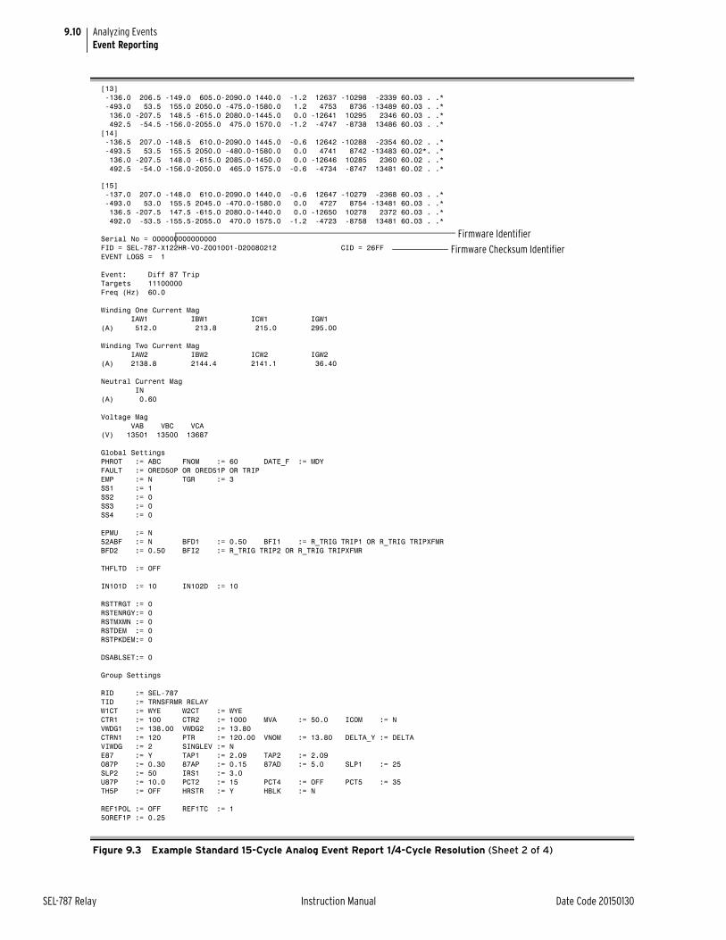
9.10
SEL-787 Relay Instruction Manual Date Code 20150130
Analyzing EventsEvent Reporting
[13] -136.0 206.5 -149.0 605.0-2090.0 1440.0 -1.2 12637 -10298 -2339 60.03 . .* -493.0 53.5 155.0 2050.0 -475.0-1580.0 1.2 4753 8736 -13489 60.03 . .* 136.0 -207.5 148.5 -615.0 2080.0-1445.0 0.0 -12641 10295 2346 60.03 . .* 492.5 -54.5 -156.0-2055.0 475.0 1570.0 -1.2 -4747 -8738 13486 60.03 . .*[14] -136.5 207.0 -148.5 610.0-2090.0 1445.0 -0.6 12642 -10288 -2354 60.02 . .* -493.5 53.5 155.5 2050.0 -480.0-1580.0 0.0 4741 8742 -13483 60.02*. .* 136.0 -207.5 148.0 -615.0 2085.0-1450.0 0.0 -12646 10285 2360 60.02 . .* 492.5 -54.0 -156.0-2050.0 465.0 1575.0 -0.6 -4734 -8747 13481 60.02 . .*
[15] -137.0 207.0 -148.0 610.0-2090.0 1440.0 -0.6 12647 -10279 -2368 60.03 . .* -493.0 53.0 155.5 2045.0 -470.0-1580.0 0.0 4727 8754 -13481 60.03 . .* 136.5 -207.5 147.5 -615.0 2080.0-1440.0 0.0 -12650 10278 2372 60.03 . .* 492.0 -53.5 -155.5-2055.0 470.0 1575.0 -1.2 -4723 -8758 13481 60.03 . .*
Serial No = 000000000000000FID = SEL-787-X122HR-V0-Z001001-D20080212 CID = 26FFEVENT LOGS = 1
Event: Diff 87 TripTargets 11100000Freq (Hz) 60.0
Winding One Current Mag IAW1 IBW1 ICW1 IGW1(A) 512.0 213.8 215.0 295.00
Winding Two Current Mag IAW2 IBW2 ICW2 IGW2(A) 2138.8 2144.4 2141.1 36.40
Neutral Current Mag IN(A) 0.60
Voltage Mag VAB VBC VCA(V) 13501 13500 13687
Global SettingsPHROT := ABC FNOM := 60 DATE_F := MDY FAULT := ORED50P OR ORED51P OR TRIPEMP := N TGR := 3 SS1 := 1SS2 := 0SS3 := 0SS4 := 0
EPMU := N 52ABF := N BFD1 := 0.50 BFI1 := R_TRIG TRIP1 OR R_TRIG TRIPXFMRBFD2 := 0.50 BFI2 := R_TRIG TRIP2 OR R_TRIG TRIPXFMR
THFLTD := OFF
IN101D := 10 IN102D := 10
RSTTRGT := 0RSTENRGY:= 0RSTMXMN := 0RSTDEM := 0RSTPKDEM:= 0
DSABLSET:= 0
Group Settings
RID := SEL-787 TID := TRNSFRMR RELAY W1CT := WYE W2CT := WYE CTR1 := 100 CTR2 := 1000 MVA := 50.0 ICOM := N VWDG1 := 138.00 VWDG2 := 13.80 CTRN1 := 120 PTR := 120.00 VNOM := 13.80 DELTA_Y := DELTA VIWDG := 2 SINGLEV := N E87 := Y TAP1 := 2.09 TAP2 := 2.09 O87P := 0.30 87AP := 0.15 87AD := 5.0 SLP1 := 25 SLP2 := 50 IRS1 := 3.0 U87P := 10.0 PCT2 := 15 PCT4 := OFF PCT5 := 35 TH5P := OFF HRSTR := Y HBLK := N
REF1POL := OFF REF1TC := 150REF1P := 0.25
Figure 9.3 Example Standard 15-Cycle Analog Event Report 1/4-Cycle Resolution (Sheet 2 of 4)
Firmware Checksum Identifier
Firmware Identifier
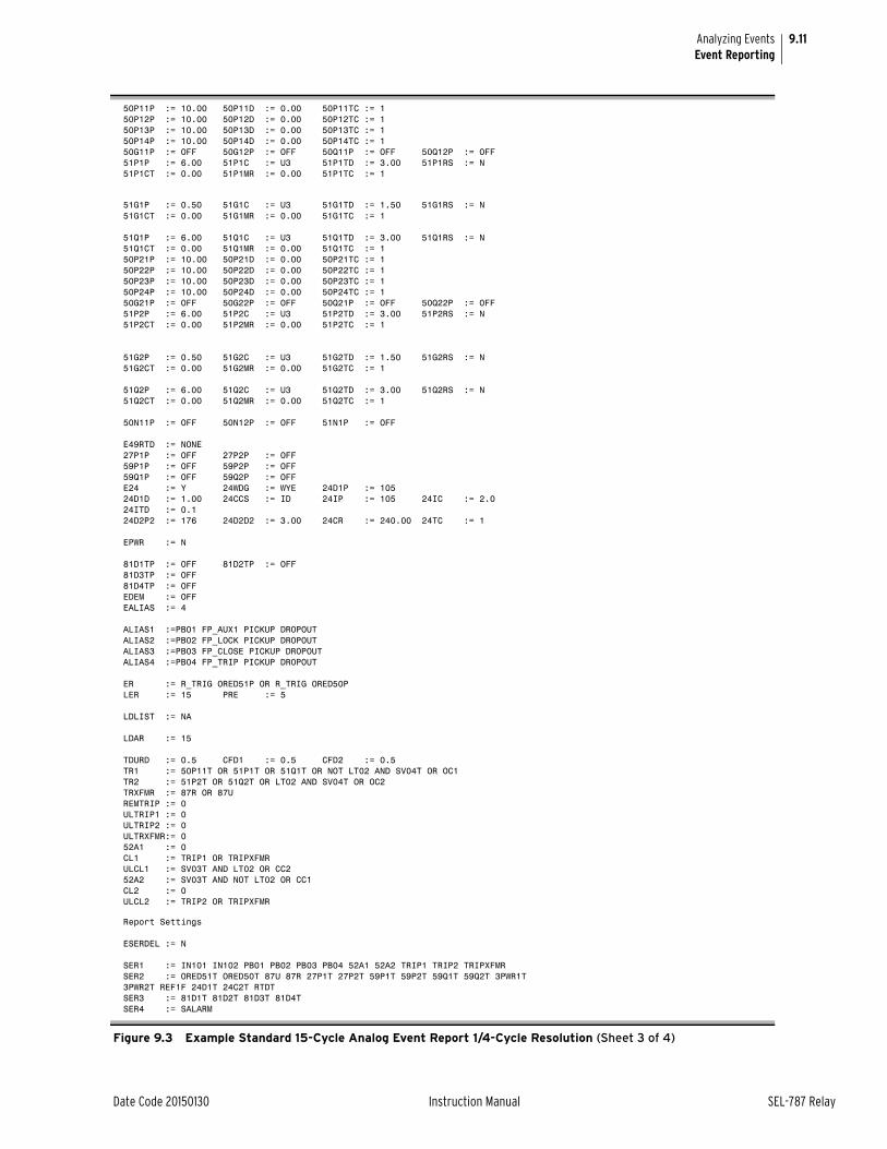
9.11
Date Code 20150130 Instruction Manual SEL-787 Relay
Analyzing EventsEvent Reporting
50P11P := 10.00 50P11D := 0.00 50P11TC := 150P12P := 10.00 50P12D := 0.00 50P12TC := 150P13P := 10.00 50P13D := 0.00 50P13TC := 150P14P := 10.00 50P14D := 0.00 50P14TC := 150G11P := OFF 50G12P := OFF 50Q11P := OFF 50Q12P := OFF 51P1P := 6.00 51P1C := U3 51P1TD := 3.00 51P1RS := N 51P1CT := 0.00 51P1MR := 0.00 51P1TC := 1
51G1P := 0.50 51G1C := U3 51G1TD := 1.50 51G1RS := N 51G1CT := 0.00 51G1MR := 0.00 51G1TC := 1
51Q1P := 6.00 51Q1C := U3 51Q1TD := 3.00 51Q1RS := N 51Q1CT := 0.00 51Q1MR := 0.00 51Q1TC := 150P21P := 10.00 50P21D := 0.00 50P21TC := 150P22P := 10.00 50P22D := 0.00 50P22TC := 150P23P := 10.00 50P23D := 0.00 50P23TC := 150P24P := 10.00 50P24D := 0.00 50P24TC := 150G21P := OFF 50G22P := OFF 50Q21P := OFF 50Q22P := OFF 51P2P := 6.00 51P2C := U3 51P2TD := 3.00 51P2RS := N 51P2CT := 0.00 51P2MR := 0.00 51P2TC := 1
51G2P := 0.50 51G2C := U3 51G2TD := 1.50 51G2RS := N 51G2CT := 0.00 51G2MR := 0.00 51G2TC := 1
51Q2P := 6.00 51Q2C := U3 51Q2TD := 3.00 51Q2RS := N 51Q2CT := 0.00 51Q2MR := 0.00 51Q2TC := 1
50N11P := OFF 50N12P := OFF 51N1P := OFF
E49RTD := NONE 27P1P := OFF 27P2P := OFF 59P1P := OFF 59P2P := OFF 59Q1P := OFF 59Q2P := OFF E24 := Y 24WDG := WYE 24D1P := 105 24D1D := 1.00 24CCS := ID 24IP := 105 24IC := 2.0 24ITD := 0.1 24D2P2 := 176 24D2D2 := 3.00 24CR := 240.00 24TC := 1
EPWR := N
81D1TP := OFF 81D2TP := OFF 81D3TP := OFF 81D4TP := OFF EDEM := OFF EALIAS := 4
ALIAS1 :=PB01 FP_AUX1 PICKUP DROPOUTALIAS2 :=PB02 FP_LOCK PICKUP DROPOUTALIAS3 :=PB03 FP_CLOSE PICKUP DROPOUTALIAS4 :=PB04 FP_TRIP PICKUP DROPOUT
ER := R_TRIG ORED51P OR R_TRIG ORED50PLER := 15 PRE := 5
LDLIST := NA
LDAR := 15
TDURD := 0.5 CFD1 := 0.5 CFD2 := 0.5 TR1 := 50P11T OR 51P1T OR 51Q1T OR NOT LT02 AND SV04T OR OC1TR2 := 51P2T OR 51Q2T OR LT02 AND SV04T OR OC2TRXFMR := 87R OR 87UREMTRIP := 0ULTRIP1 := 0ULTRIP2 := 0ULTRXFMR:= 052A1 := 0CL1 := TRIP1 OR TRIPXFMRULCL1 := SV03T AND LT02 OR CC252A2 := SV03T AND NOT LT02 OR CC1CL2 := 0ULCL2 := TRIP2 OR TRIPXFMR
Report Settings
ESERDEL := N
SER1 := IN101 IN102 PB01 PB02 PB03 PB04 52A1 52A2 TRIP1 TRIP2 TRIPXFMR SER2 := ORED51T ORED50T 87U 87R 27P1T 27P2T 59P1T 59P2T 59Q1T 59Q2T 3PWR1T 3PWR2T REF1F 24D1T 24C2T RTDT SER3 := 81D1T 81D2T 81D3T 81D4T SER4 := SALARM
Figure 9.3 Example Standard 15-Cycle Analog Event Report 1/4-Cycle Resolution (Sheet 3 of 4)
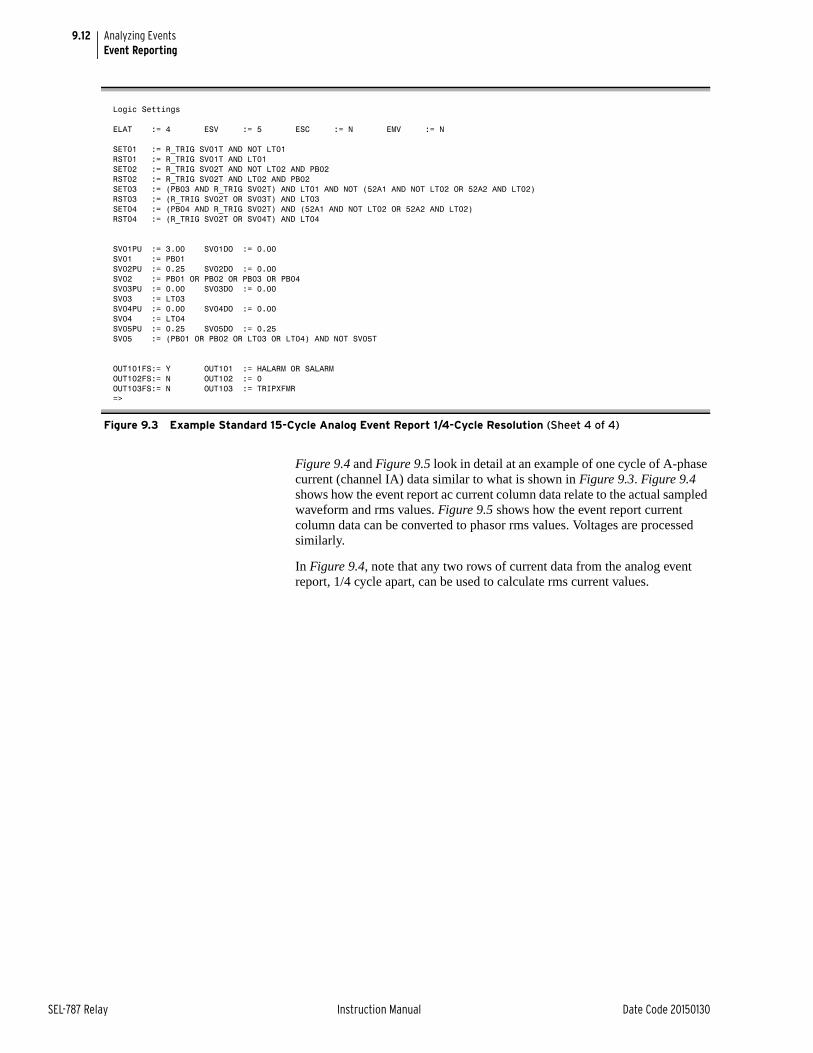
9.12
SEL-787 Relay Instruction Manual Date Code 20150130
Analyzing EventsEvent Reporting
Figure 9.4 and Figure 9.5 look in detail at an example of one cycle of A-phase current (channel IA) data similar to what is shown in Figure 9.3. Figure 9.4 shows how the event report ac current column data relate to the actual sampled waveform and rms values. Figure 9.5 shows how the event report current column data can be converted to phasor rms values. Voltages are processed similarly.
In Figure 9.4, note that any two rows of current data from the analog event report, 1/4 cycle apart, can be used to calculate rms current values.
Logic Settings
ELAT := 4 ESV := 5 ESC := N EMV := N
SET01 := R_TRIG SV01T AND NOT LT01RST01 := R_TRIG SV01T AND LT01SET02 := R_TRIG SV02T AND NOT LT02 AND PB02RST02 := R_TRIG SV02T AND LT02 AND PB02SET03 := (PB03 AND R_TRIG SV02T) AND LT01 AND NOT (52A1 AND NOT LT02 OR 52A2 AND LT02)RST03 := (R_TRIG SV02T OR SV03T) AND LT03SET04 := (PB04 AND R_TRIG SV02T) AND (52A1 AND NOT LT02 OR 52A2 AND LT02)RST04 := (R_TRIG SV02T OR SV04T) AND LT04
SV01PU := 3.00 SV01DO := 0.00 SV01 := PB01SV02PU := 0.25 SV02DO := 0.00 SV02 := PB01 OR PB02 OR PB03 OR PB04SV03PU := 0.00 SV03DO := 0.00 SV03 := LT03SV04PU := 0.00 SV04DO := 0.00 SV04 := LT04SV05PU := 0.25 SV05DO := 0.25 SV05 := (PB01 OR PB02 OR LT03 OR LT04) AND NOT SV05T
OUT101FS:= Y OUT101 := HALARM OR SALARMOUT102FS:= N OUT102 := 0OUT103FS:= N OUT103 := TRIPXFMR=>
Figure 9.3 Example Standard 15-Cycle Analog Event Report 1/4-Cycle Resolution (Sheet 4 of 4)
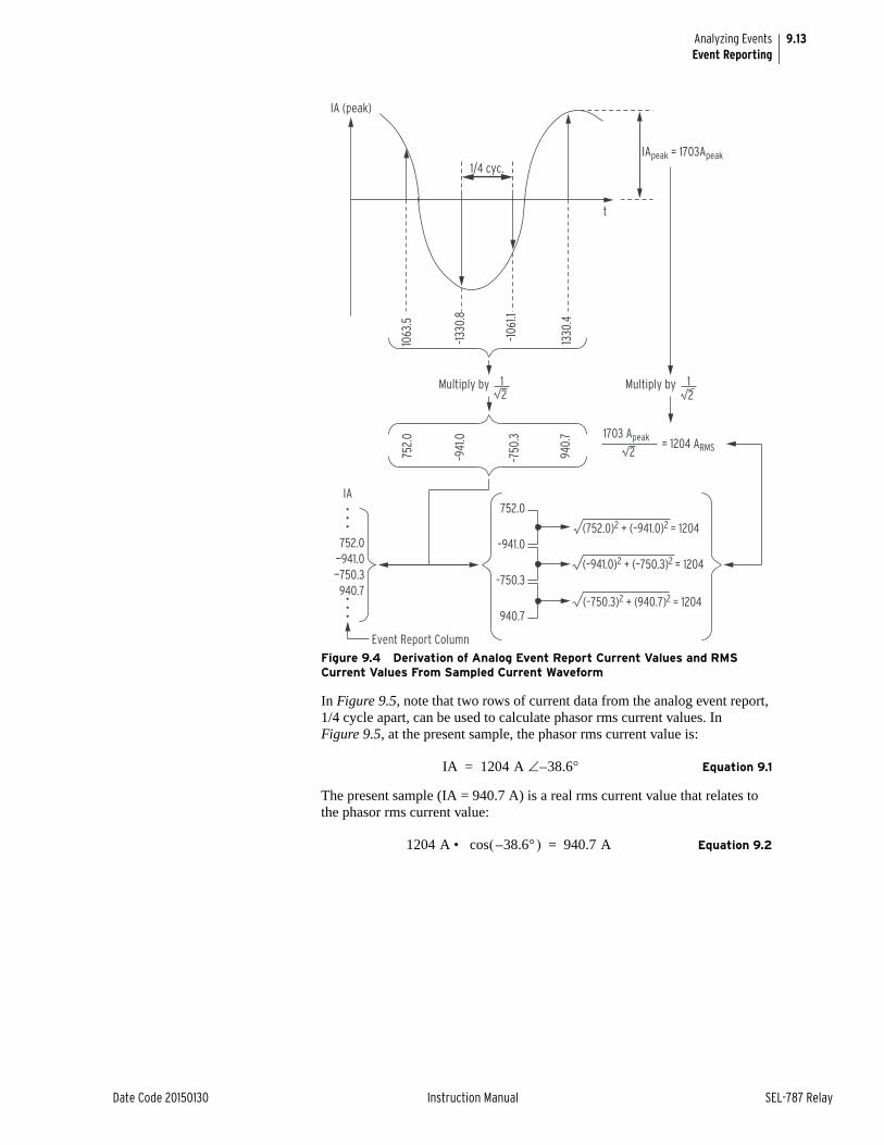
9.13
Date Code 20150130 Instruction Manual SEL-787 Relay
Analyzing EventsEvent Reporting
Figure 9.4 Derivation of Analog Event Report Current Values and RMS Current Values From Sampled Current Waveform
In Figure 9.5, note that two rows of current data from the analog event report, 1/4 cycle apart, can be used to calculate phasor rms current values. In Figure 9.5, at the present sample, the phasor rms current value is:
Equation 9.1
The present sample (IA = 940.7 A) is a real rms current value that relates to the phasor rms current value:
Equation 9.2
(752.0)2 + (–941.0)2 = 1204
(–750.3)2 + (940.7)2 = 1204
(–941.0)2 + (–750.3)2 = 1204
Event Report Column
752.0
–941.0
–750.3
940.7
IA
122
2
Multiply by1Multiply by
940.
7
–941
.0
–750
.3
752.
0
–106
1.1
–133
0.8
1063
.5
1330
.4
t
IA (peak)
1/4 cyc.IApeak = 1703Apeak
1703 Apeak= 1204 ARMS
•••
752.0—941.0—750.3940.7
•••
IA 1204 A 38.6–=
1204 A cos 38.6– • 940.7 A=
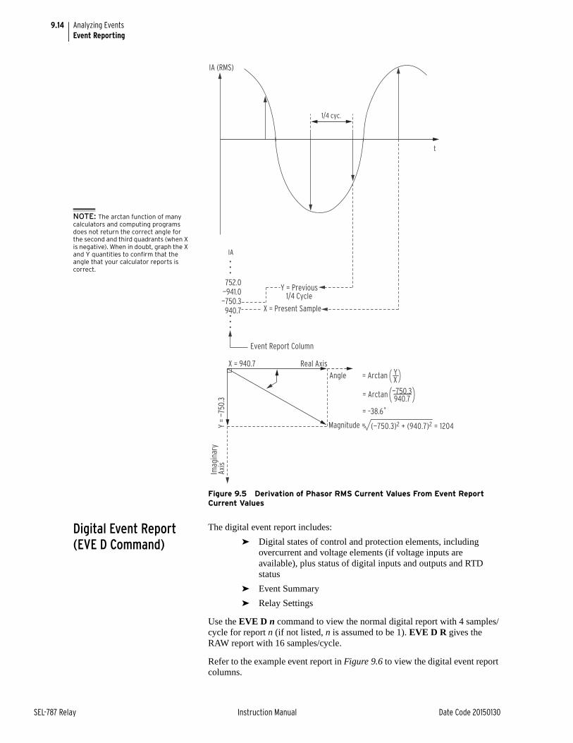
9.14
SEL-787 Relay Instruction Manual Date Code 20150130
Analyzing EventsEvent Reporting
Figure 9.5 Derivation of Phasor RMS Current Values From Event Report Current Values
Digital Event Report (EVE D Command)
The digital event report includes:
➤ Digital states of control and protection elements, including overcurrent and voltage elements (if voltage inputs are available), plus status of digital inputs and outputs and RTD status
➤ Event Summary
➤ Relay Settings
Use the EVE D n command to view the normal digital report with 4 samples/cycle for report n (if not listed, n is assumed to be 1). EVE D R gives the RAW report with 16 samples/cycle.
Refer to the example event report in Figure 9.6 to view the digital event report columns.
IA (RMS)
t
IA
Event Report Column
Magnitude =
X = 940.7
Y =
—750
.3
Angle = Arctan
= Arctan
YX—750.3940.7
= –38.6˚
Real Axis
Axis
Imag
inar
y
1/4 cyc.
(—750.3)2 + (940.7)2 = 1204
Y = Previous 1/4 Cycle
•••
752.0—941.0
—750.3 940.7
•••
X = Present Sample
NOTE: The arctan function of many calculators and computing programs does not return the correct angle for the second and third quadrants (when X is negative). When in doubt, graph the X and Y quantities to confirm that the angle that your calculator reports is correct.
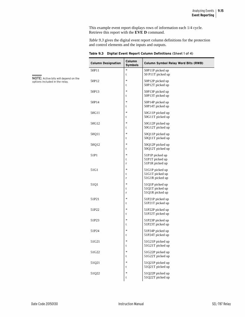
9.15
Date Code 20150130 Instruction Manual SEL-787 Relay
Analyzing EventsEvent Reporting
This example event report displays rows of information each 1/4 cycle. Retrieve this report with the EVE D command.
Table 9.3 gives the digital event report column definitions for the protection and control elements and the inputs and outputs.
Table 9.3 Digital Event Report Column Definitions (Sheet 1 of 4)
Column DesignationColumn Symbols
Column Symbol Relay Word Bits (RWB)
50P11 *t
50P11P picked up50 P11T picked up
50P12 *t
50P12P picked up50P12T picked up
50P13 *t
50P13P picked up50P13T picked up
50P14 *t
50P14P picked up50P14T picked up
50G11 *t
50G11P picked up50G11T picked up
50G12 *t
50G12P picked up50G12T picked up
50Q11 *t
50Q11P picked up50Q11T picked up
50Q12 *t
50Q12P picked up50Q12T picked up
51P1 *tr
51P1P picked up51P1T picked up51P1R picked up
51G1 *tr
51G1P picked up51G1T picked up51G1R picked up
51Q1 *tr
51Q1P picked up51Q1T picked up51Q1R picked up
51P21 *t
51P21P picked up51P21T picked up
51P22 *t
51P22P picked up51P22T picked up
51P23 *t
51P23P picked up51P23T picked up
51P24 *t
51P24P picked up51P24T picked up
51G21 *t
51G21P picked up51G21T picked up
51G22 *t
51G22P picked up51G22T picked up
51Q21 *t
51Q21P picked up51Q21T picked up
51Q22 *t
51Q22P picked up51Q22T picked up
NOTE: Active bits will depend on the options included in the relay.
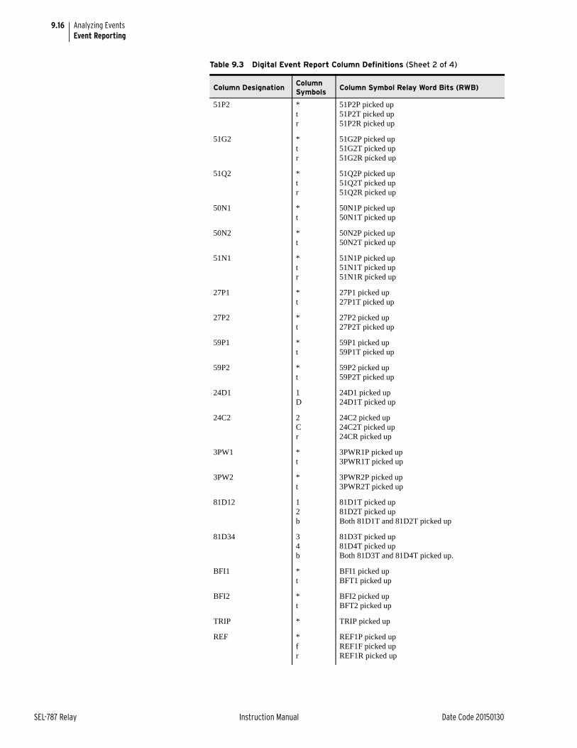
9.16
SEL-787 Relay Instruction Manual Date Code 20150130
Analyzing EventsEvent Reporting
51P2 *tr
51P2P picked up51P2T picked up51P2R picked up
51G2 *tr
51G2P picked up51G2T picked up51G2R picked up
51Q2 *tr
51Q2P picked up51Q2T picked up51Q2R picked up
50N1 *t
50N1P picked up50N1T picked up
50N2 *t
50N2P picked up50N2T picked up
51N1 *tr
51N1P picked up51N1T picked up51N1R picked up
27P1 *t
27P1 picked up27P1T picked up
27P2 *t
27P2 picked up27P2T picked up
59P1 *t
59P1 picked up59P1T picked up
59P2 *t
59P2 picked up59P2T picked up
24D1 1D
24D1 picked up24D1T picked up
24C2 2Cr
24C2 picked up24C2T picked up24CR picked up
3PW1 *t
3PWR1P picked up3PWR1T picked up
3PW2 *t
3PWR2P picked up3PWR2T picked up
81D12 12b
81D1T picked up81D2T picked upBoth 81D1T and 81D2T picked up
81D34 34b
81D3T picked up81D4T picked upBoth 81D3T and 81D4T picked up.
BFI1 *t
BFI1 picked upBFT1 picked up
BFI2 *t
BFI2 picked upBFT2 picked up
TRIP * TRIP picked up
REF *fr
REF1P picked upREF1F picked upREF1R picked up
Table 9.3 Digital Event Report Column Definitions (Sheet 2 of 4)
Column DesignationColumn Symbols
Column Symbol Relay Word Bits (RWB)
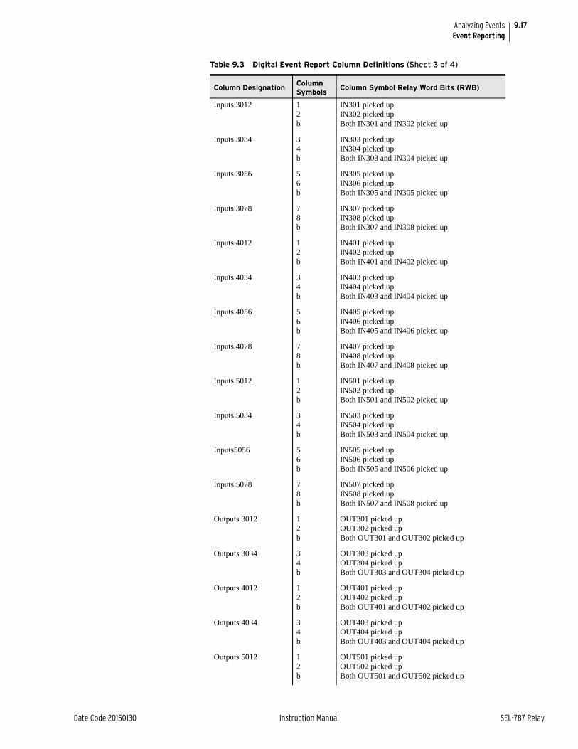
9.17
Date Code 20150130 Instruction Manual SEL-787 Relay
Analyzing EventsEvent Reporting
Inputs 3012 12b
IN301 picked upIN302 picked upBoth IN301 and IN302 picked up
Inputs 3034 34b
IN303 picked upIN304 picked upBoth IN303 and IN304 picked up
Inputs 3056 56b
IN305 picked upIN306 picked upBoth IN305 and IN305 picked up
Inputs 3078 78b
IN307 picked upIN308 picked upBoth IN307 and IN308 picked up
Inputs 4012 12b
IN401 picked upIN402 picked upBoth IN401 and IN402 picked up
Inputs 4034 34b
IN403 picked upIN404 picked upBoth IN403 and IN404 picked up
Inputs 4056 56b
IN405 picked upIN406 picked upBoth IN405 and IN406 picked up
Inputs 4078 78b
IN407 picked upIN408 picked upBoth IN407 and IN408 picked up
Inputs 5012 12b
IN501 picked upIN502 picked upBoth IN501 and IN502 picked up
Inputs 5034 34b
IN503 picked upIN504 picked upBoth IN503 and IN504 picked up
Inputs5056 56b
IN505 picked upIN506 picked upBoth IN505 and IN506 picked up
Inputs 5078 78b
IN507 picked upIN508 picked upBoth IN507 and IN508 picked up
Outputs 3012 12b
OUT301 picked upOUT302 picked upBoth OUT301 and OUT302 picked up
Outputs 3034 34b
OUT303 picked upOUT304 picked upBoth OUT303 and OUT304 picked up
Outputs 4012 12b
OUT401 picked upOUT402 picked upBoth OUT401 and OUT402 picked up
Outputs 4034 34b
OUT403 picked upOUT404 picked upBoth OUT403 and OUT404 picked up
Outputs 5012 12b
OUT501 picked upOUT502 picked upBoth OUT501 and OUT502 picked up
Table 9.3 Digital Event Report Column Definitions (Sheet 3 of 4)
Column DesignationColumn Symbols
Column Symbol Relay Word Bits (RWB)
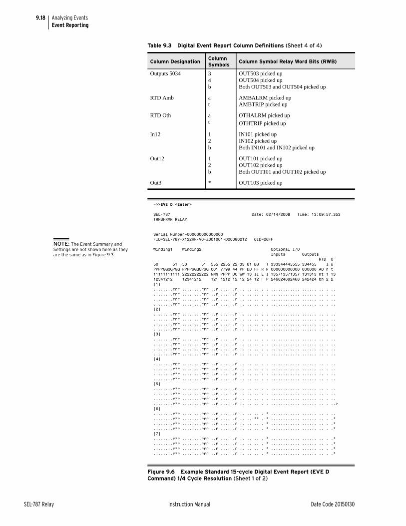
9.18
SEL-787 Relay Instruction Manual Date Code 20150130
Analyzing EventsEvent Reporting
Outputs 5034 34b
OUT503 picked upOUT504 picked upBoth OUT503 and OUT504 picked up
RTD Amb at
AMBALRM picked upAMBTRIP picked up
RTD Oth at
OTHALRM picked up
OTHTRIP picked up
In12 12b
IN101 picked upIN102 picked upBoth IN101 and IN102 picked up
Out12 12b
OUT101 picked upOUT102 picked upBoth OUT101 and OUT102 picked up
Out3 * OUT103 picked up
=>>EVE D <Enter> SEL-787 Date: 02/14/2008 Time: 13:09:57.353TRNSFRMR RELAY
Serial Number=000000000000000FID=SEL-787-X122HR-V0-Z001001-D20080212 CID=26FF
Winding1 Winding2 Optional I/O Inputs Outputs RTD O50 51 50 51 555 2255 22 33 81 BB T 333344445555 334455 I uPPPPGGQQPGQ PPPPGGQQPGQ 001 7799 44 PP DD FF R R 000000000000 000000 AO n t11111111111 22222222222 NNN PPPP DC WW 13 II E I 135713571357 131313 mt 1 1312341212 12341212 121 1212 12 12 24 12 F P 246824682468 242424 bh 2 2[1]........rrr ........rrr ..r .... .r .. .. .. . . ............ ...... .. . .. ........rrr ........rrr ..r .... .r .. .. .. . . ............ ...... .. . .. ........rrr ........rrr ..r .... .r .. .. .. . . ............ ...... .. . .. ........rrr ........rrr ..r .... .r .. .. .. . . ............ ...... .. . .. [2]........rrr ........rrr ..r .... .r .. .. .. . . ............ ...... .. . .. ........rrr ........rrr ..r .... .r .. .. .. . . ............ ...... .. . .. ........rrr ........rrr ..r .... .r .. .. .. . . ............ ...... .. . .. ........rrr ........rrr ..r .... .r .. .. .. . . ............ ...... .. . .. [3]........rrr ........rrr ..r .... .r .. .. .. . . ............ ...... .. . .. ........rrr ........rrr ..r .... .r .. .. .. . . ............ ...... .. . .. ........rrr ........rrr ..r .... .r .. .. .. . . ............ ...... .. . .. ........rrr ........rrr ..r .... .r .. .. .. . . ............ ...... .. . .. [4]........rrr ........rrr ..r .... .r .. .. .. . . ............ ...... .. . .. ........r*r ........rrr ..r .... .r .. .. .. . . ............ ...... .. . .. ........r*r ........rrr ..r .... .r .. .. .. . . ............ ...... .. . .. ........r*r ........rrr ..r .... .r .. .. .. . . ............ ...... .. . .. [5]........r*r ........rrr ..r .... .r .. .. .. . . ............ ...... .. . .. ........r*r ........rrr ..r .... .r .. .. .. . . ............ ...... .. . .. ........r*r ........rrr ..r .... .r .. .. .. . . ............ ...... .. . .. ........r*r ........rrr ..r .... .r .. .. .. . . ............ ...... .. . ..>[6]........r*r ........rrr ..r .... .r .. .. .. . * ............ ...... .. . .. ........r*r ........rrr ..r .... .r .. .. ** . * ............ ...... .. . .* ........r*r ........rrr ..r .... .r .. .. .. . * ............ ...... .. . .* ........r*r ........rrr ..r .... .r .. .. .. . * ............ ...... .. . .* [7]........r*r ........rrr ..r .... .r .. .. .. . * ............ ...... .. . .* ........r*r ........rrr ..r .... .r .. .. .. . * ............ ...... .. . .* ........r*r ........rrr ..r .... .r .. .. .. . * ............ ...... .. . .* ........r*r ........rrr ..r .... .r .. .. .. . * ............ ...... .. . .*
Figure 9.6 Example Standard 15-cycle Digital Event Report (EVE D Command) 1/4 Cycle Resolution (Sheet 1 of 2)
Table 9.3 Digital Event Report Column Definitions (Sheet 4 of 4)
Column DesignationColumn Symbols
Column Symbol Relay Word Bits (RWB)
NOTE: The Event Summary and Settings are not shown here as they are the same as in Figure 9.3.
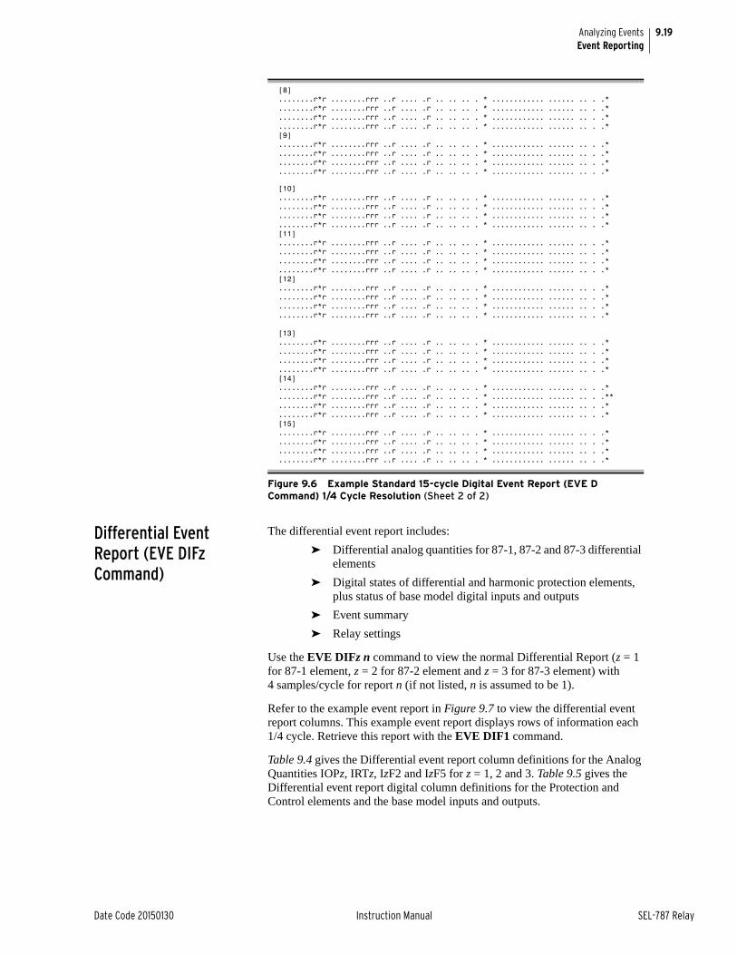
9.19
Date Code 20150130 Instruction Manual SEL-787 Relay
Analyzing EventsEvent Reporting
Differential Event Report (EVE DIFz Command)
The differential event report includes:
➤ Differential analog quantities for 87-1, 87-2 and 87-3 differential elements
➤ Digital states of differential and harmonic protection elements, plus status of base model digital inputs and outputs
➤ Event summary
➤ Relay settings
Use the EVE DIFz n command to view the normal Differential Report (z = 1 for 87-1 element, z = 2 for 87-2 element and z = 3 for 87-3 element) with 4 samples/cycle for report n (if not listed, n is assumed to be 1).
Refer to the example event report in Figure 9.7 to view the differential event report columns. This example event report displays rows of information each 1/4 cycle. Retrieve this report with the EVE DIF1 command.
Table 9.4 gives the Differential event report column definitions for the Analog Quantities IOPz, IRTz, IzF2 and IzF5 for z = 1, 2 and 3. Table 9.5 gives the Differential event report digital column definitions for the Protection and Control elements and the base model inputs and outputs.
[8]........r*r ........rrr ..r .... .r .. .. .. . * ............ ...... .. . .* ........r*r ........rrr ..r .... .r .. .. .. . * ............ ...... .. . .* ........r*r ........rrr ..r .... .r .. .. .. . * ............ ...... .. . .* ........r*r ........rrr ..r .... .r .. .. .. . * ............ ...... .. . .* [9]........r*r ........rrr ..r .... .r .. .. .. . * ............ ...... .. . .* ........r*r ........rrr ..r .... .r .. .. .. . * ............ ...... .. . .* ........r*r ........rrr ..r .... .r .. .. .. . * ............ ...... .. . .* ........r*r ........rrr ..r .... .r .. .. .. . * ............ ...... .. . .*
[10]........r*r ........rrr ..r .... .r .. .. .. . * ............ ...... .. . .* ........r*r ........rrr ..r .... .r .. .. .. . * ............ ...... .. . .* ........r*r ........rrr ..r .... .r .. .. .. . * ............ ...... .. . .* ........r*r ........rrr ..r .... .r .. .. .. . * ............ ...... .. . .* [11]........r*r ........rrr ..r .... .r .. .. .. . * ............ ...... .. . .* ........r*r ........rrr ..r .... .r .. .. .. . * ............ ...... .. . .* ........r*r ........rrr ..r .... .r .. .. .. . * ............ ...... .. . .* ........r*r ........rrr ..r .... .r .. .. .. . * ............ ...... .. . .* [12]........r*r ........rrr ..r .... .r .. .. .. . * ............ ...... .. . .* ........r*r ........rrr ..r .... .r .. .. .. . * ............ ...... .. . .* ........r*r ........rrr ..r .... .r .. .. .. . * ............ ...... .. . .* ........r*r ........rrr ..r .... .r .. .. .. . * ............ ...... .. . .*
[13]........r*r ........rrr ..r .... .r .. .. .. . * ............ ...... .. . .* ........r*r ........rrr ..r .... .r .. .. .. . * ............ ...... .. . .* ........r*r ........rrr ..r .... .r .. .. .. . * ............ ...... .. . .* ........r*r ........rrr ..r .... .r .. .. .. . * ............ ...... .. . .* [14]........r*r ........rrr ..r .... .r .. .. .. . * ............ ...... .. . .* ........r*r ........rrr ..r .... .r .. .. .. . * ............ ...... .. . .**........r*r ........rrr ..r .... .r .. .. .. . * ............ ...... .. . .* ........r*r ........rrr ..r .... .r .. .. .. . * ............ ...... .. . .* [15]........r*r ........rrr ..r .... .r .. .. .. . * ............ ...... .. . .* ........r*r ........rrr ..r .... .r .. .. .. . * ............ ...... .. . .* ........r*r ........rrr ..r .... .r .. .. .. . * ............ ...... .. . .* ........r*r ........rrr ..r .... .r .. .. .. . * ............ ...... .. . .*
Figure 9.6 Example Standard 15-cycle Digital Event Report (EVE D Command) 1/4 Cycle Resolution (Sheet 2 of 2)
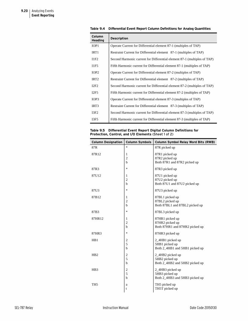
9.20
SEL-787 Relay Instruction Manual Date Code 20150130
Analyzing EventsEvent Reporting
Table 9.4 Differential Event Report Column Definitions for Analog Quantities
Column Heading
Description
IOP1 Operate Current for Differential element 87-1 (multiples of TAP)
IRT1 Restraint Current for Differential element 87-1 (multiples of TAP)
I1F2 Second Harmonic current for Differential element 87-1 (multiples of TAP)
I1F5 Fifth Harmonic current for Differential element 87-1 (multiples of TAP)
IOP2 Operate Current for Differential element 87-2 (multiples of TAP)
IRT2 Restraint Current for Differential element 87-2 (multiples of TAP)
I2F2 Second Harmonic current for Differential element 87-2 (multiples of TAP)
I2F5 Fifth Harmonic current for Differential element 87-2 (multiples of TAP)
IOP3 Operate Current for Differential element 87-3 (multiples of TAP)
IRT3 Restraint Current for Differential element 87-3 (multiples of TAP)
I3F2 Second Harmonic current for Differential element 87-3 (multiples of TAP)
I3F5 Fifth Harmonic current for Differential element 87-3 (multiples of TAP)
Table 9.5 Differential Event Report Digital Column Definitions for Protection, Control, and I/O Elements (Sheet 1 of 2)
Column Designation Column Symbols Column Symbol Relay Word Bits (RWB)
87R * 87R picked up
87R12 12b
87R1 picked up87R2 picked upBoth 87R1 and 87R2 picked up
87R3 * 87R3 picked up
87U12 12b
87U1 picked up87U2 picked upBoth 87U1 and 87U2 picked up
87U3 * 87U3 picked up
87B12 12b
87BL1 picked up87BL2 picked upBoth 87BL1 and 87BL2 picked up
87B3 * 87BL3 picked up
87HR12 12b
87HR1 picked up87HR2 picked upBoth 87HR1 and 87HR2 picked up
87HR3 * 87HR3 picked up
HB1 25b
2_4HB1 picked up5HB1 picked upBoth 2_4HB1 and 5HB1 picked up
HB2 25b
2_4HB2 picked up5HB2 picked upBoth 2_4HB2 and 5HB2 picked up
HB3 25b
2_4HB3 picked up5HB3 picked upBoth 2_4HB3 and 5HB3 picked up
TH5 at
TH5 picked upTH5T picked up
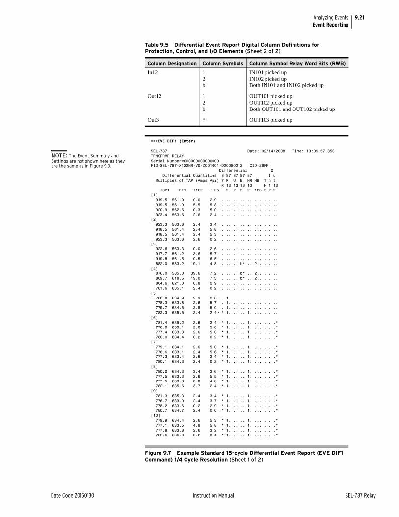
9.21
Date Code 20150130 Instruction Manual SEL-787 Relay
Analyzing EventsEvent Reporting
In12 12b
IN101 picked upIN102 picked upBoth IN101 and IN102 picked up
Out12 12b
OUT101 picked upOUT102 picked upBoth OUT101 and OUT102 picked up
Out3 * OUT103 picked up
=>>EVE DIF1 (Enter)
SEL-787 Date: 02/14/2008 Time: 13:09:57.353TRNSFRMR RELAYSerial Number=000000000000000FID=SEL-787-X122HR-V0-Z001001-D20080212 CID=26FF Differential O Differential Quantities 8 87 87 87 87 I u Multiples of TAP (Amps Api) 7 R U B HR HB T n t R 13 13 13 13 H 1 13 IOP1 IRT1 I1F2 I1F5 2 2 2 2 123 5 2 2 [1] 919.5 561.9 0.0 2.9 . .. .. .. .. ... . . .. 919.5 561.9 5.5 5.8 . .. .. .. .. ... . . .. 920.9 562.6 0.3 5.0 . .. .. .. .. ... . . .. 923.4 563.6 2.6 2.4 . .. .. .. .. ... . . ..[2] 923.3 563.6 2.4 3.4 . .. .. .. .. ... . . .. 918.5 561.4 2.4 5.8 . .. .. .. .. ... . . .. 918.5 561.4 2.4 5.3 . .. .. .. .. ... . . .. 923.3 563.6 2.6 0.2 . .. .. .. .. ... . . ..[3] 922.6 563.3 0.0 2.6 . .. .. .. .. ... . . .. 917.7 561.2 3.6 5.7 . .. .. .. .. ... . . .. 919.8 561.5 0.5 6.5 . .. .. .. .. ... . . .. 882.0 583.2 19.1 4.8 . .. .. b* .. 2.. . . ..[4] 876.0 585.0 39.6 7.2 . .. .. b* .. 2.. . . .. 809.7 618.5 19.0 7.3 . .. .. b* .. 2.. . . .. 804.6 621.3 0.8 2.9 . .. .. .. .. ... . . .. 781.6 635.1 2.4 0.2 . .. .. .. .. ... . . ..[5] 780.8 634.9 2.9 2.6 . 1. .. .. .. ... . . .. 778.3 633.8 2.6 5.7 . 1. .. .. .. ... . . .. 779.7 634.5 2.9 5.0 . 1. .. .. .. ... . . .. 782.3 635.5 2.4 2.4> * 1. .. .. 1. ... . . ..[6] 781.4 635.2 2.6 2.4 * 1. .. .. 1. ... . . .* 776.6 633.1 2.6 5.0 * 1. .. .. 1. ... . . .* 777.4 633.3 2.6 5.0 * 1. .. .. 1. ... . . .* 780.0 634.4 0.2 0.2 * 1. .. .. 1. ... . . .*[7] 779.1 634.1 2.6 5.0 * 1. .. .. 1. ... . . .* 776.6 633.1 2.4 5.6 * 1. .. .. 1. ... . . .* 777.3 633.4 2.6 2.4 * 1. .. .. 1. ... . . .* 780.1 634.3 2.4 0.2 * 1. .. .. 1. ... . . .*[8] 780.0 634.3 3.4 2.6 * 1. .. .. 1. ... . . .* 777.5 633.3 2.6 5.5 * 1. .. .. 1. ... . . .* 777.5 633.3 0.0 4.8 * 1. .. .. 1. ... . . .* 782.1 635.6 3.7 2.4 * 1. .. .. 1. ... . . .*[9] 781.3 635.3 2.4 3.4 * 1. .. .. 1. ... . . .* 776.7 633.0 2.4 3.7 * 1. .. .. 1. ... . . .* 778.2 633.6 0.2 2.9 * 1. .. .. 1. ... . . .* 780.7 634.7 2.4 0.0 * 1. .. .. 1. ... . . .*[10] 779.9 634.4 2.6 5.3 * 1. .. .. 1. ... . . .* 777.1 633.5 4.8 5.8 * 1. .. .. 1. ... . . .* 777.8 633.8 2.6 3.2 * 1. .. .. 1. ... . . .* 782.6 636.0 0.2 3.4 * 1. .. .. 1. ... . . .*
Figure 9.7 Example Standard 15-cycle Differential Event Report (EVE DIF1 Command) 1/4 Cycle Resolution (Sheet 1 of 2)
Table 9.5 Differential Event Report Digital Column Definitions for Protection, Control, and I/O Elements (Sheet 2 of 2)
Column Designation Column Symbols Column Symbol Relay Word Bits (RWB)
NOTE: The Event Summary and Settings are not shown here as they are the same as in Figure 9.3.
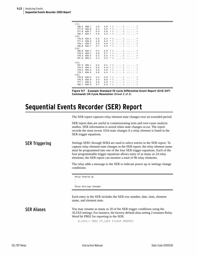
9.22
SEL-787 Relay Instruction Manual Date Code 20150130
Analyzing EventsSequential Events Recorder (SER) Report
Sequential Events Recorder (SER) ReportThe SER report captures relay element state changes over an extended period.
SER report data are useful in commissioning tests and root-cause analysis studies. SER information is stored when state changes occur. The report records the most recent 1024 state changes if a relay element is listed in the SER trigger equations.
SER Triggering Settings SER1 through SER4 are used to select entries in the SER report. To capture relay element state changes in the SER report, the relay element name must be programmed into one of the four SER trigger equations. Each of the four programmable trigger equations allows entry of as many as 24 relay elements; the SER report can monitor a total of 96 relay elements.
The relay adds a message to the SER to indicate power up or settings change conditions:
Each entry in the SER includes the SER row number, date, time, element name, and element state.
SER Aliases You may rename as many as 20 of the SER trigger conditions using the ALIAS settings. For instance, the factory-default alias setting 2 renames Relay Word bit PB02 for reporting in the SER:
ALIAS2:= PB02 FP_LOCK PICKUP DROPOUT
[11] 782.5 636.1 2.6 3.6 * 1. .. .. 1. ... . . .* 777.9 633.8 3.4 3.6 * 1. .. .. 1. ... . . .* 777.9 633.7 0.3 2.6 * 1. .. .. 1. ... . . .* 780.7 634.7 5.6 2.2 * 1. .. .. 1. ... . . .*[12] 779.9 634.4 0.2 3.4 * 1. .. .. 1. ... . . .* 777.4 633.3 4.8 5.5 * 1. .. .. 1. ... . . .* 778.1 633.7 3.2 4.8 * 1. .. .. 1. ... . . .* 780.6 634.7 3.7 0.0 * 1. .. .. 1. ... . . .*[13] 780.6 634.7 0.2 2.6 * 1. .. .. 1. ... . . .* 778.0 633.7 3.6 5.7 * 1. .. .. 1. ... . . .* 779.4 634.4 2.4 5.0 * 1. .. .. 1. ... . . .* 781.9 635.4 2.4 2.2 * 1. .. .. 1. ... . . .*
[14] 781.2 635.1 0.2 3.4 * 1. .. .. 1. ... . . .* 778.4 634.2 3.6 5.5* * 1. .. .. 1. ... . . .* 779.2 634.5 2.6 4.8 * 1. .. .. 1. ... . . .* 779.7 634.3 2.6 2.4 * 1. .. .. 1. ... . . .*[15] 778.8 634.0 2.4 5.6 * 1. .. .. 1. ... . . .* 776.3 632.9 3.4 6.9 * 1. .. .. 1. ... . . .* 777.1 633.3 2.6 4.8 * 1. .. .. 1. ... . . .* 782.1 635.3 3.7 0.3 * 1. .. .. 1. ... . . .*
Figure 9.7 Example Standard 15-cycle Differential Event Report (EVE DIF1 Command) 1/4 Cycle Resolution (Sheet 2 of 2)
Relay Powered Up...Relay Settings Changed
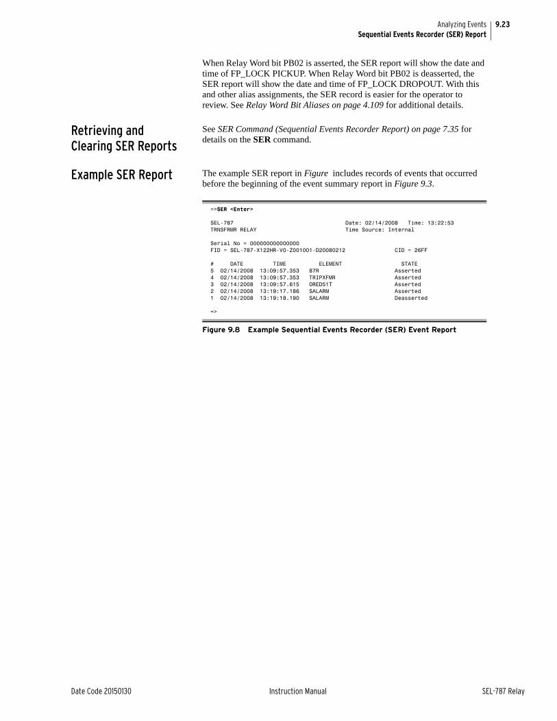
9.23
Date Code 20150130 Instruction Manual SEL-787 Relay
Analyzing EventsSequential Events Recorder (SER) Report
When Relay Word bit PB02 is asserted, the SER report will show the date and time of FP_LOCK PICKUP. When Relay Word bit PB02 is deasserted, the SER report will show the date and time of FP_LOCK DROPOUT. With this and other alias assignments, the SER record is easier for the operator to review. See Relay Word Bit Aliases on page 4.109 for additional details.
Retrieving and Clearing SER Reports
See SER Command (Sequential Events Recorder Report) on page 7.35 for details on the SER command.
Example SER Report The example SER report in Figure includes records of events that occurred before the beginning of the event summary report in Figure 9.3.
=>SER <Enter>
SEL-787 Date: 02/14/2008 Time: 13:22:53TRNSFRMR RELAY Time Source: Internal
Serial No = 000000000000000FID = SEL-787-X122HR-V0-Z001001-D20080212 CID = 26FF
# DATE TIME ELEMENT STATE5 02/14/2008 13:09:57.353 87R Asserted4 02/14/2008 13:09:57.353 TRIPXFMR Asserted3 02/14/2008 13:09:57.615 ORED51T Asserted2 02/14/2008 13:19:17.186 SALARM Asserted1 02/14/2008 13:19:18.190 SALARM Deasserted
=>
Figure 9.8 Example Sequential Events Recorder (SER) Event Report

This page intentionally left blank
Date Code 20150130 Instruction Manual SEL-787 Relay
Section 10Testing and Troubleshooting
Instruction Manual
OverviewRelay testing is typically divided into two categories:
➤ Tests performed at the time the relay is installed or commissioned
➤ Tests performed periodically once the relay is in service
This section provides information on both types of testing for the SEL-787 Transformer Protection Relay. Because the SEL-787 is equipped with extensive self-tests, traditional periodic test procedures may be eliminated or greatly reduced.
Should a problem arise during either commissioning or periodic tests, the section on Troubleshooting on page 10.15 provides a guide to isolating and correcting the problem.
Testing ToolsSerial Port Commands
The following serial port commands assist you during relay testing.
The METER command shows the ac currents and voltages (magnitude and phase angle) presented to the relay in primary values. In addition, the command shows power system frequency. Compare these quantities against other devices of known accuracy. The METER command is available at the serial ports and front-panel display. See Section 7: Communications and Section 8: Front-Panel Operations.
The relay generates a 15- or 64-cycle event report in response to faults or disturbances. Each report contains current and voltage information, relay element states, and input/output contact information. If you question the relay response or your test method, use the event report for more information. The EVENT command is available at the serial ports. See Section 9: Analyzing Events.
The relay provides a Sequential Events Recorder (SER) event report that time-tags changes in relay element and input/output contact states. The SER provides a convenient means to verify the pickup/dropout of any element in the relay. The SER command is available at the serial ports. See Section 9: Analyzing Events.
Use the TARGET command to view the state of relay control inputs, relay outputs, and relay elements individually during a test. The TARGET command is available at the serial ports and the front panel. See Section 7: Communications and Section 8: Front-Panel Operations.
WARNINGBefore working on a CT circuit, first apply a short to the secondary winding of the CT.
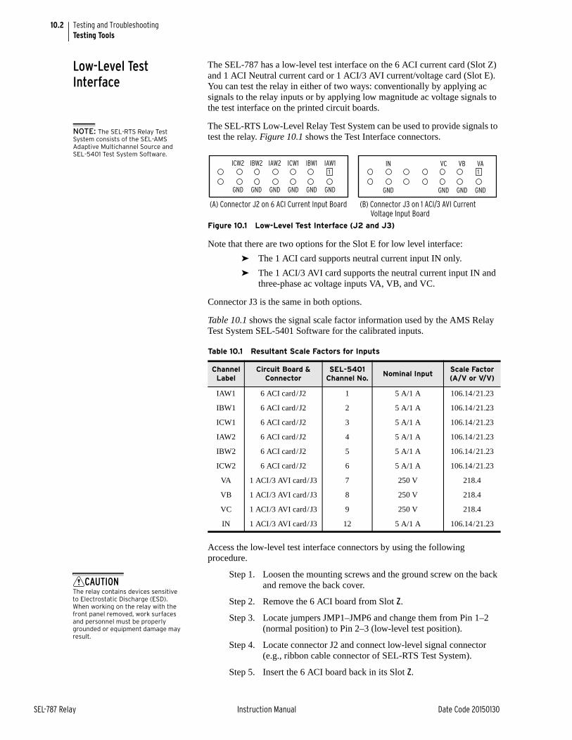
10.2
SEL-787 Relay Instruction Manual Date Code 20150130
Testing and TroubleshootingTesting Tools
Low-Level Test Interface
The SEL-787 has a low-level test interface on the 6 ACI current card (Slot Z) and 1 ACI Neutral current card or 1 ACI/3 AVI current/voltage card (Slot E). You can test the relay in either of two ways: conventionally by applying ac signals to the relay inputs or by applying low magnitude ac voltage signals to the test interface on the printed circuit boards.
The SEL-RTS Low-Level Relay Test System can be used to provide signals to test the relay. Figure 10.1 shows the Test Interface connectors.
Figure 10.1 Low-Level Test Interface (J2 and J3)
Note that there are two options for the Slot E for low level interface:
➤ The 1 ACI card supports neutral current input IN only.
➤ The 1 ACI/3 AVI card supports the neutral current input IN and three-phase ac voltage inputs VA, VB, and VC.
Connector J3 is the same in both options.
Table 10.1 shows the signal scale factor information used by the AMS Relay Test System SEL-5401 Software for the calibrated inputs.
Access the low-level test interface connectors by using the following procedure.
Step 1. Loosen the mounting screws and the ground screw on the back and remove the back cover.
Step 2. Remove the 6 ACI board from Slot Z.
Step 3. Locate jumpers JMP1–JMP6 and change them from Pin 1–2 (normal position) to Pin 2–3 (low-level test position).
Step 4. Locate connector J2 and connect low-level signal connector (e.g., ribbon cable connector of SEL-RTS Test System).
Step 5. Insert the 6 ACI board back in its Slot Z.
Table 10.1 Resultant Scale Factors for Inputs
Channel Label
Circuit Board & Connector
SEL-5401 Channel No.
Nominal InputScale Factor (A/V or V/V)
IAW1 6 ACI card/J2 1 5 A/1 A 106.14/21.23
IBW1 6 ACI card/J2 2 5 A/1 A 106.14/21.23
ICW1 6 ACI card/J2 3 5 A/1 A 106.14/21.23
IAW2 6 ACI card/J2 4 5 A/1 A 106.14/21.23
IBW2 6 ACI card/J2 5 5 A/1 A 106.14/21.23
ICW2 6 ACI card/J2 6 5 A/1 A 106.14/21.23
VA 1 ACI/3 AVI card/J3 7 250 V 218.4
VB 1 ACI/3 AVI card/J3 8 250 V 218.4
VC 1 ACI/3 AVI card/J3 9 250 V 218.4
IN 1 ACI/3 AVI card/J3 12 5 A/1 A 106.14/21.23
NOTE: The SEL-RTS Relay Test System consists of the SEL-AMS Adaptive Multichannel Source and SEL-5401 Test System Software.
(A) Connector J2 on 6 ACI Current Input Board (B) Connector J3 on 1 ACI/3 AVI Current Voltage Input Board
1IN VC VB VA
GND GND GND GND
1ICW2 IBW2 IAW2 ICW1 IBW1 IAW1
GND GND GND GND GND GND
CAUTIONThe relay contains devices sensitive to Electrostatic Discharge (ESD). When working on the relay with the front panel removed, work surfaces and personnel must be properly grounded or equipment damage may result.
10.3
Date Code 20150130 Instruction Manual SEL-787 Relay
Testing and TroubleshootingCommissioning Tests
Step 6. Remove the 1 ACI/3 AVI board or 1 ACI board from Slot E.
Step 7. Locate jumper JMP1 and change it from Pin 1-2 (normal position) to Pin 2-3 (low-level test position)
Step 8. Locate connector J3 and connect low-level signal connector (e.g., ribbon cable connector of SEL-RTS Test System).
Step 9. Insert the board back into Slot E.
Refer to the SEL-RTS Instruction Manual for additional detail.
When simulating a delta PT connection, DELTA_Y := DELTA, with the low-level test interface referenced in Figure 10.1, apply the following signals:
➤ Apply low-level test signal VAB to Pin VA.
➤ Apply low-level test signal –VBC (equivalent to VCB) to Pin VC.
➤ Do not apply any signal to pin VB.
Commissioning TestsSEL performs a complete functional check and calibration of each SEL-787 before it is shipped. This helps to ensure that you receive a relay that operates correctly and accurately. Commissioning tests confirm that the relay is properly connected including the control signal inputs and outputs.
The following connection tests help you enter settings into the SEL-787 and verify that the relay is properly connected. Brief functional tests ensure that the relay settings are correct. It is unnecessary to test every element, timer, and function in these tests. Modify the procedure as necessary to conform to your standard practices. Use the procedure at initial relay installation; you should not need to repeat it unless major changes are made to the relay electrical connections.
Required Equipment ➤ The SEL-787, installed and connected according to your protection design
➤ A PC with serial port, terminal emulation software, and serial communications cable
➤ SEL-787 Settings Sheets with settings appropriate to your application and protection design
➤ The ac and dc elementary schematics and wiring diagrams for this relay installation
➤ A continuity tester
➤ A protective relay ac test source
➢ Minimum: single-phase voltage and current with phase angle control
➢ Preferred: three-phase voltage and current with phase angle control
Connection Tests Step 1. Remove control voltage and ac signals from the SEL-787 by opening the appropriate breaker(s) or removing fuses.
Step 2. Isolate the relay contact assigned to be the TRIP output.
NOTE: The 14-pin connectors of the SEL-RTS ribbon cable C750A can be used. The connectors are not keyed; make sure Pin 1 is connected to the IAW1/VA channel on the 6 ACI and 1 ACI/3 AVI boards, respectively.
10.4
SEL-787 Relay Instruction Manual Date Code 20150130
Testing and TroubleshootingCommissioning Tests
Step 3. Verify correct ac and dc connections by performing point-to-point continuity checks on the associated circuits.
Step 4. Apply ac or dc control voltage to the relay.
After the relay is energized, the front-panel green ENABLED LED should illuminate.
Step 5. Use the appropriate serial cable (SEL cable C234A or equivalent) to connect a PC to the relay.
Step 6. Start the PC terminal emulation software and establish communication with the relay.
Refer to Section 7: Communications for more information on serial port communications.
Step 7. Set the correct relay time and date by using either the front-panel or serial port commands (TIME hh:mm:ss and DATE mm/dd/yy commands).
Step 8. Using the SET, SET P, SET G, SET L, and SET R serial port commands, enter the relay settings from the settings sheets for your application.
Step 9. If you are connecting an external SEL-2600 RTD Module, follow the substeps below; otherwise continue with the next step.
a. Connect the fiber-optic cable to the RTD Module fiber-optic output.
b. Plug the relay end of the fiber-optic cable into the relay fiber-optic Rx input (Port 2).
Step 10. Verify the relay ac connections.
Step 11. Connect the ac test source current or voltage to the appropriate relay terminals.
NOTE: Make sure the current transformer secondary windings are shorted before they are disconnected from the relay.
a. Disconnect the current transformer and voltage transformer (if present) secondaries from the relay prior to applying test source quantities.
b. If you set the relay to accept phase-to-ground voltages (DELTA_Y := WYE), set the current and/or voltage phase angles as shown in Figure 10.2.
c. If you set the relay to accept delta voltages (DELTA_Y := DELTA), set the current and/or voltage phase angles as shown in Figure 10.3.
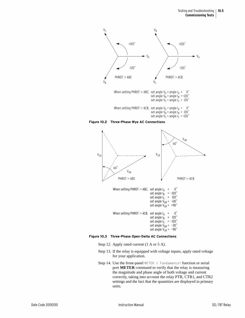
10.5
Date Code 20150130 Instruction Manual SEL-787 Relay
Testing and TroubleshootingCommissioning Tests
Figure 10.2 Three-Phase Wye AC Connections
Figure 10.3 Three-Phase Open-Delta AC Connections
Step 12. Apply rated current (1 A or 5 A).
Step 13. If the relay is equipped with voltage inputs, apply rated voltage for your application.
Step 14. Use the front-panel METER > Fundamental function or serial port METER command to verify that the relay is measuring the magnitude and phase angle of both voltage and current correctly, taking into account the relay PTR, CTR1, and CTR2 settings and the fact that the quantities are displayed in primary units.
+120˚
–120˚
VC
VB VC
VA
PHROT := ABC
+120˚
–120˚
PHROT := ACB
VB
VA
When setting PHROT := ABC, set angle VA = angle IA = 0˚ set angle VB = angle IB = —120˚ set angle VC = angle IC = 120˚
When setting PHROT := ACB, set angle VA = angle IA = 0˚ set angle VB = angle IB = 120˚ set angle VC = angle IC = —120˚
60˚VAB
VCB
PHROT := ABC
60˚VAB
VCB
PHROT := ACB
When setting PHROT := ABC, set angle IA = 0˚ set angle IB = —120˚ set angle IC = 120˚ set angle VAB = +30˚ set angle VCB = +90˚
When setting PHROT := ACB, set angle IA = 0˚ set angle IB = 120˚ set angle IC = —120˚ set angle VAB = —30˚ set angle VCB = —90˚
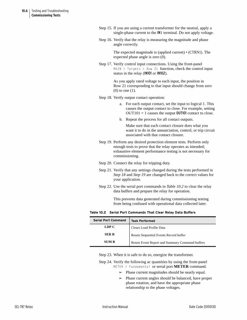
10.6
SEL-787 Relay Instruction Manual Date Code 20150130
Testing and TroubleshootingCommissioning Tests
Step 15. If you are using a current transformer for the neutral, apply a single-phase current to the IN1 terminal. Do not apply voltage.
Step 16. Verify that the relay is measuring the magnitude and phase angle correctly.
The expected magnitude is (applied current) • (CTRN1). The expected phase angle is zero (0).
Step 17. Verify control input connections. Using the front-panel MAIN > Targets > Row 21 function, check the control input status in the relay (IN101 or IN102).
As you apply rated voltage to each input, the position in Row 21 corresponding to that input should change from zero (0) to one (1).
Step 18. Verify output contact operation:
a. For each output contact, set the input to logical 1. This causes the output contact to close. For example, setting OUT101 = 1 causes the output OUT101 contact to close.
b. Repeat the process for all contact outputs.
Make sure that each contact closure does what you want it to do in the annunciation, control, or trip circuit associated with that contact closure.
Step 19. Perform any desired protection element tests. Perform only enough tests to prove that the relay operates as intended; exhaustive element performance testing is not necessary for commissioning.
Step 20. Connect the relay for tripping duty.
Step 21. Verify that any settings changed during the tests performed in Step 18 and Step 19 are changed back to the correct values for your application.
Step 22. Use the serial port commands in Table 10.2 to clear the relay data buffers and prepare the relay for operation.
This prevents data generated during commissioning testing from being confused with operational data collected later.
Step 23. When it is safe to do so, energize the transformer.
Step 24. Verify the following ac quantities by using the front-panel METER > Fundamental or serial port METER command.
➢ Phase current magnitudes should be nearly equal.
➢ Phase current angles should be balanced, have proper phase rotation, and have the appropriate phase relationship to the phase voltages.
Table 10.2 Serial Port Commands That Clear Relay Data Buffers
Serial Port Command Task Performed
LDP C Clears Load Profile Data
SER R Resets Sequential Events Record buffer
SUM R Resets Event Report and Summary Command buffers
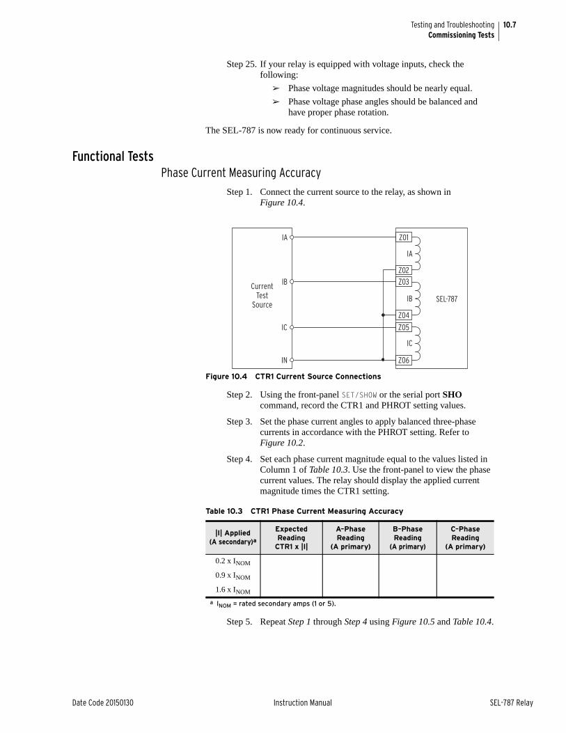
10.7
Date Code 20150130 Instruction Manual SEL-787 Relay
Testing and TroubleshootingCommissioning Tests
Step 25. If your relay is equipped with voltage inputs, check the following:
➢ Phase voltage magnitudes should be nearly equal.
➢ Phase voltage phase angles should be balanced and have proper phase rotation.
The SEL-787 is now ready for continuous service.
Functional TestsPhase Current Measuring Accuracy
Step 1. Connect the current source to the relay, as shown in Figure 10.4.
Figure 10.4 CTR1 Current Source Connections
Step 2. Using the front-panel SET/SHOW or the serial port SHO command, record the CTR1 and PHROT setting values.
Step 3. Set the phase current angles to apply balanced three-phase currents in accordance with the PHROT setting. Refer to Figure 10.2.
Step 4. Set each phase current magnitude equal to the values listed in Column 1 of Table 10.3. Use the front-panel to view the phase current values. The relay should display the applied current magnitude times the CTR1 setting.
Step 5. Repeat Step 1 through Step 4 using Figure 10.5 and Table 10.4.
Table 10.3 CTR1 Phase Current Measuring Accuracy
|I| Applied(A secondary)a
a INOM = rated secondary amps (1 or 5).
Expected Reading
CTR1 x |I|
A–Phase Reading
(A primary)
B–Phase Reading
(A primary)
C–Phase Reading
(A primary)
0.2 x INOM
0.9 x INOM
1.6 x INOM
SEL-787
CurrentTest
Source
IA
IB
IC
IC
IB
IA
IN
Z01
Z02Z03
Z04
Z05
Z06
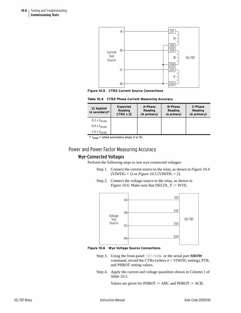
10.8
SEL-787 Relay Instruction Manual Date Code 20150130
Testing and TroubleshootingCommissioning Tests
Figure 10.5 CTR2 Current Source Connections
Power and Power Factor Measuring AccuracyWye-Connected Voltages
Perform the following steps to test wye-connected voltages:
Step 1. Connect the current source to the relay, as shown in Figure 10.4 (VIWDG = 1) or Figure 10.5 (VIWDG = 2).
Step 2. Connect the voltage source to the relay, as shown in Figure 10.6. Make sure that DELTA_Y := WYE.
Figure 10.6 Wye Voltage Source Connections
Step 3. Using the front-panel SET/SHOW or the serial port SHOW command, record the CTRn (where n = VIWDG setting), PTR, and PHROT setting values.
Step 4. Apply the current and voltage quantities shown in Column 1 of Table 10.5.
Values are given for PHROT := ABC and PHROT := ACB.
Table 10.4 CTR2 Phase Current Measuring Accuracy
|I| Applied(A secondary)a
a INOM = rated secondary amps (1 or 5).
Expected Reading
CTR2 x |I|
A–Phase Reading
(A primary)
B–Phase Reading
(A primary)
C–Phase Reading
(A primary)
0.2 x INOM
0.9 x INOM
1.6 x INOM
SEL-787
CurrentTest
Source
IA
IB
IC
IC
IB
IA
IN
Z07
Z08Z09
Z010
Z011
Z012
SEL-787
E01
E02
E03
E04
VoltageTest
Source
VA
VB
VC
VN
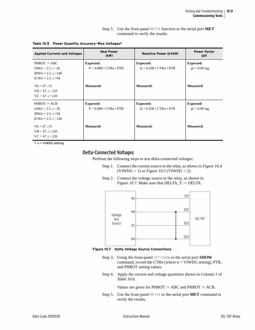
10.9
Date Code 20150130 Instruction Manual SEL-787 Relay
Testing and TroubleshootingCommissioning Tests
Step 5. Use the front-panel METER function or the serial port MET command to verify the results.
Delta-Connected VoltagesPerform the following steps to test delta-connected voltages:
Step 1. Connect the current source to the relay, as shown in Figure 10.4 (VIWDG = 1) or Figure 10.5 (VIWDG = 2).
Step 2. Connect the voltage source to the relay, as shown in Figure 10.7. Make sure that DELTA_Y := DELTA.
Figure 10.7 Delta Voltage Source Connections
Step 3. Using the front-panel SET/SHOW or the serial port SHOW command, record the CTRn (where n = VIWDG setting), PTR, and PHROT setting values.
Step 4. Apply the current and voltage quantities shown in Column 1 of Table 10.6.
Values are given for PHROT := ABC and PHROT := ACB.
Step 5. Use the front-panel METER or the serial port MET command to verify the results.
Table 10.5 Power Quantity Accuracy—Wye Voltagesa
Applied Currents and VoltagesReal Power
(kW)Reactive Power (kVAR)
Power Factor(pf)
PHROT := ABC
IAWn = 2.5 IBWn = 2.5 146
ICWn = 2.5 +94
Expected:P = 0.898 • CTRn • PTR
Expected:Q = 0.438 • CTRn • PTR
Expected:pf = 0.90 lag
VA = 67 0
VB = 67 120
VC = 67 +120
Measured: Measured: Measured:
PHROT := ACB
IAWn = 2.5 26
IBWn = 2.5 +94
ICWn = 2.5 146
Expected:P = 0.898 • CTRn • PTR
Expected:Q = 0.438 • CTRn • PTR
Expected:pf = 0.90 lag
VA = 67 0
VB = 67 120
VC = 67 120
Measured: Measured: Measured:
a n = VIWDG setting
SEL-787
E01
E02
E03
E04
VoltageTest
Source
VA
VB
VC
VN
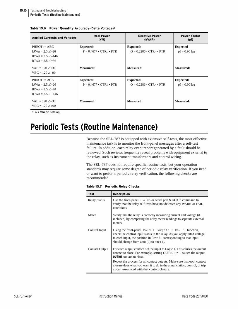
10.10
SEL-787 Relay Instruction Manual Date Code 20150130
Testing and TroubleshootingPeriodic Tests (Routine Maintenance)
Periodic Tests (Routine Maintenance)Because the SEL-787 is equipped with extensive self-tests, the most effective maintenance task is to monitor the front-panel messages after a self-test failure. In addition, each relay event report generated by a fault should be reviewed. Such reviews frequently reveal problems with equipment external to the relay, such as instrument transformers and control wiring.
The SEL-787 does not require specific routine tests, but your operation standards may require some degree of periodic relay verification. If you need or want to perform periodic relay verification, the following checks are recommended.
Table 10.6 Power Quantity Accuracy—Delta Voltagesa
Applied Currents and VoltagesReal Power
(kW)Reactive Power
(kVAR)Power Factor
(pf)
PHROT := ABC
IAWn = 2.5 –26
IBWn = 2.5 –146
ICWn = 2.5 +94
Expected:P = 0.4677 • CTRn • PTR
Expected:Q = 0.2286 • CTRn • PTR
Expectedpf = 0.90 lag
VAB = 120 +30
VBC = 120 –90
Measured: Measured: Measured:
PHROT := ACB
IAWn = 2.5 26
IBWn = 2.5 +94
ICWn = 2.5 146
Expected:P = 0.4677 • CTRn • PTR
Expected:Q = 0.2286 • CTRn • PTR
Expected:pf = 0.90 lag
VAB = 120 30
VBC = 120 90
Measured: Measured: Measured:
a n = VIWDG setting
Table 10.7 Periodic Relay Checks
Test Description
Relay Status Use the front-panel STATUS or serial port STATUS command to verify that the relay self-tests have not detected any WARN or FAIL conditions.
Meter Verify that the relay is correctly measuring current and voltage (if included) by comparing the relay meter readings to separate external meters.
Control Input Using the front-panel MAIN > Targets > Row 21 function, check the control input status in the relay. As you apply rated voltage to each input, the position in Row 21 corresponding to that input should change from zero (0) to one (1).
Contact Output For each output contact, set the input to Logic 1. This causes the output contact to close. For example, setting OUT101 := 1 causes the output OUT101 contact to close.
Repeat the process for all contact outputs. Make sure that each contact closure does what you want it to do in the annunciation, control, or trip circuit associated with that contact closure.
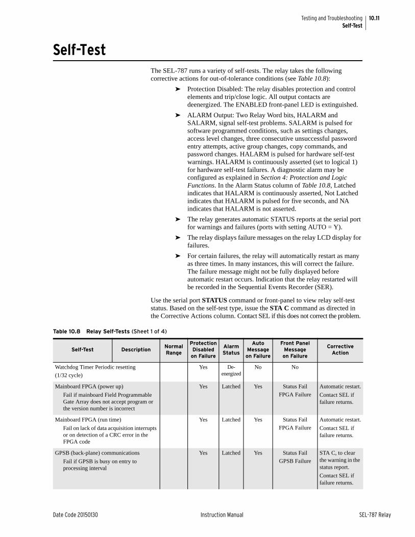
10.11
Date Code 20150130 Instruction Manual SEL-787 Relay
Testing and TroubleshootingSelf-Test
Self-TestThe SEL-787 runs a variety of self-tests. The relay takes the following corrective actions for out-of-tolerance conditions (see Table 10.8):
➤ Protection Disabled: The relay disables protection and control elements and trip/close logic. All output contacts are deenergized. The ENABLED front-panel LED is extinguished.
➤ ALARM Output: Two Relay Word bits, HALARM and SALARM, signal self-test problems. SALARM is pulsed for software programmed conditions, such as settings changes, access level changes, three consecutive unsuccessful password entry attempts, active group changes, copy commands, and password changes. HALARM is pulsed for hardware self-test warnings. HALARM is continuously asserted (set to logical 1) for hardware self-test failures. A diagnostic alarm may be configured as explained in Section 4: Protection and Logic Functions. In the Alarm Status column of Table 10.8, Latched indicates that HALARM is continuously asserted, Not Latched indicates that HALARM is pulsed for five seconds, and NA indicates that HALARM is not asserted.
➤ The relay generates automatic STATUS reports at the serial port for warnings and failures (ports with setting AUTO = Y).
➤ The relay displays failure messages on the relay LCD display for failures.
➤ For certain failures, the relay will automatically restart as many as three times. In many instances, this will correct the failure. The failure message might not be fully displayed before automatic restart occurs. Indication that the relay restarted will be recorded in the Sequential Events Recorder (SER).
Use the serial port STATUS command or front-panel to view relay self-test status. Based on the self-test type, issue the STA C command as directed in the Corrective Actions column. Contact SEL if this does not correct the problem.
Table 10.8 Relay Self-Tests (Sheet 1 of 4)
Self-Test DescriptionNormal Range
ProtectionDisabled
on Failure
AlarmStatus
AutoMessageon Failure
Front PanelMessage on Failure
CorrectiveAction
Watchdog Timer Periodic resetting
(1/32 cycle)
Yes De-energized
No No
Mainboard FPGA (power up)
Fail if mainboard Field Programmable Gate Array does not accept program or the version number is incorrect
Yes Latched Yes Status Fail
FPGA Failure
Automatic restart.
Contact SEL if failure returns.
Mainboard FPGA (run time)
Fail on lack of data acquisition interrupts or on detection of a CRC error in the FPGA code
Yes Latched Yes Status Fail
FPGA Failure
Automatic restart.
Contact SEL if failure returns.
GPSB (back-plane) communications
Fail if GPSB is busy on entry to processing interval
Yes Latched Yes Status Fail
GPSB Failure
STA C, to clear the warning in the status report.
Contact SEL if failure returns.
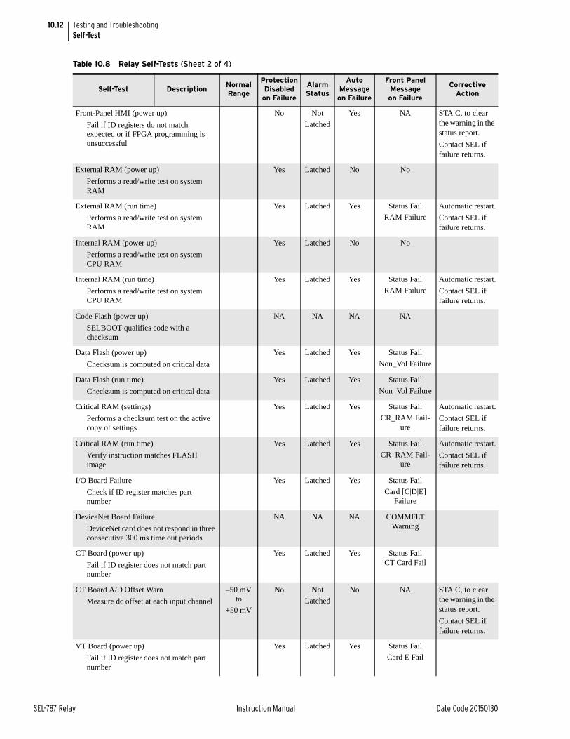
10.12
SEL-787 Relay Instruction Manual Date Code 20150130
Testing and TroubleshootingSelf-Test
Front-Panel HMI (power up)
Fail if ID registers do not match expected or if FPGA programming is unsuccessful
No Not
Latched
Yes NA STA C, to clear the warning in the status report.
Contact SEL if failure returns.
External RAM (power up)
Performs a read/write test on system RAM
Yes Latched No No
External RAM (run time)
Performs a read/write test on system RAM
Yes Latched Yes Status Fail
RAM Failure
Automatic restart.
Contact SEL if failure returns.
Internal RAM (power up)
Performs a read/write test on system CPU RAM
Yes Latched No No
Internal RAM (run time)
Performs a read/write test on system CPU RAM
Yes Latched Yes Status Fail
RAM Failure
Automatic restart.
Contact SEL if failure returns.
Code Flash (power up)
SELBOOT qualifies code with a checksum
NA NA NA NA
Data Flash (power up)
Checksum is computed on critical data
Yes Latched Yes Status Fail
Non_Vol Failure
Data Flash (run time)
Checksum is computed on critical data
Yes Latched Yes Status Fail
Non_Vol Failure
Critical RAM (settings)
Performs a checksum test on the active copy of settings
Yes Latched Yes Status Fail
CR_RAM Fail-ure
Automatic restart.
Contact SEL if failure returns.
Critical RAM (run time)
Verify instruction matches FLASH image
Yes Latched Yes Status Fail
CR_RAM Fail-ure
Automatic restart.
Contact SEL if failure returns.
I/O Board Failure
Check if ID register matches part number
Yes Latched Yes Status Fail
Card [C|D|E] Failure
DeviceNet Board Failure
DeviceNet card does not respond in three consecutive 300 ms time out periods
NA NA NA COMMFLTWarning
CT Board (power up)
Fail if ID register does not match part number
Yes Latched Yes Status FailCT Card Fail
CT Board A/D Offset Warn
Measure dc offset at each input channel
–50 mV to
+50 mV
No Not
Latched
No NA STA C, to clear the warning in the status report.
Contact SEL if failure returns.
VT Board (power up)
Fail if ID register does not match part number
Yes Latched Yes Status Fail
Card E Fail
Table 10.8 Relay Self-Tests (Sheet 2 of 4)
Self-Test DescriptionNormal Range
ProtectionDisabled
on Failure
AlarmStatus
AutoMessageon Failure
Front PanelMessage on Failure
CorrectiveAction
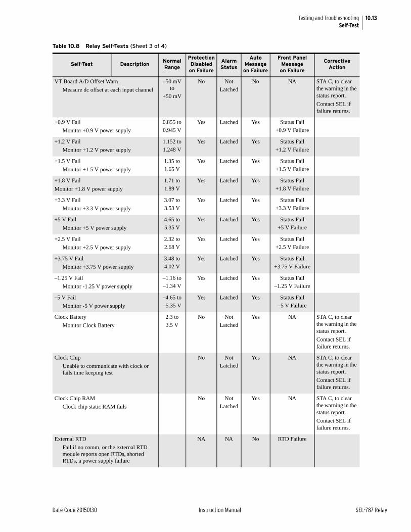
10.13
Date Code 20150130 Instruction Manual SEL-787 Relay
Testing and TroubleshootingSelf-Test
VT Board A/D Offset Warn
Measure dc offset at each input channel
–50 mV to
+50 mV
No Not
Latched
No NA STA C, to clear the warning in the status report.
Contact SEL if failure returns.
+0.9 V Fail
Monitor +0.9 V power supply
0.855 to
0.945 V
Yes Latched Yes Status Fail
+0.9 V Failure
+1.2 V Fail
Monitor +1.2 V power supply
1.152 to
1.248 V
Yes Latched Yes Status Fail
+1.2 V Failure
+1.5 V Fail
Monitor +1.5 V power supply
1.35 to
1.65 V
Yes Latched Yes Status Fail
+1.5 V Failure
+1.8 V Fail
Monitor +1.8 V power supply
1.71 to
1.89 V
Yes Latched Yes Status Fail
+1.8 V Failure
+3.3 V Fail
Monitor +3.3 V power supply
3.07 to
3.53 V
Yes Latched Yes Status Fail
+3.3 V Failure
+5 V Fail
Monitor +5 V power supply
4.65 to
5.35 V
Yes Latched Yes Status Fail
+5 V Failure
+2.5 V Fail
Monitor +2.5 V power supply
2.32 to
2.68 V
Yes Latched Yes Status Fail
+2.5 V Failure
+3.75 V Fail
Monitor +3.75 V power supply
3.48 to
4.02 V
Yes Latched Yes Status Fail
+3.75 V Failure
–1.25 V Fail
Monitor -1.25 V power supply
–1.16 to
–1.34 V
Yes Latched Yes Status Fail
–1.25 V Failure
–5 V Fail
Monitor -5 V power supply
–4.65 to
–5.35 V
Yes Latched Yes Status Fail
–5 V Failure
Clock Battery
Monitor Clock Battery
2.3 to
3.5 V
No Not
Latched
Yes NA STA C, to clear the warning in the status report.
Contact SEL if failure returns.
Clock Chip
Unable to communicate with clock or fails time keeping test
No Not
Latched
Yes NA STA C, to clear the warning in the status report.
Contact SEL if failure returns.
Clock Chip RAM
Clock chip static RAM fails
No Not
Latched
Yes NA STA C, to clear the warning in the status report.
Contact SEL if failure returns.
External RTD
Fail if no comm, or the external RTD module reports open RTDs, shorted RTDs, a power supply failure
NA NA No RTD Failure
Table 10.8 Relay Self-Tests (Sheet 3 of 4)
Self-Test DescriptionNormal Range
ProtectionDisabled
on Failure
AlarmStatus
AutoMessageon Failure
Front PanelMessage on Failure
CorrectiveAction
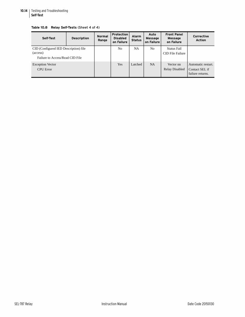
10.14
SEL-787 Relay Instruction Manual Date Code 20150130
Testing and TroubleshootingSelf-Test
CID (Configured IED Description) file (access)
Failure to Access/Read CID File
No NA No Status Fail
CID File Failure
Exception Vector
CPU Error
Yes Latched NA Vector nn
Relay Disabled
Automatic restart.
Contact SEL if failure returns.
Table 10.8 Relay Self-Tests (Sheet 4 of 4)
Self-Test DescriptionNormal Range
ProtectionDisabled
on Failure
AlarmStatus
AutoMessageon Failure
Front PanelMessage on Failure
CorrectiveAction
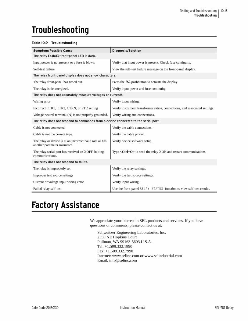
10.15
Date Code 20150130 Instruction Manual SEL-787 Relay
Testing and TroubleshootingTroubleshooting
Troubleshooting
Factory Assistance
We appreciate your interest in SEL products and services. If you have questions or comments, please contact us at:
Schweitzer Engineering Laboratories, Inc.2350 NE Hopkins CourtPullman, WA 99163-5603 U.S.A.Tel: +1.509.332.1890Fax: +1.509.332.7990Internet: www.selinc.com or www.selindustrial.comEmail: [email protected]
Table 10.9 Troubleshooting
Symptom/Possible Cause Diagnosis/Solution
The relay ENABLED front-panel LED is dark.
Input power is not present or a fuse is blown. Verify that input power is present. Check fuse continuity.
Self-test failure View the self-test failure message on the front-panel display.
The relay front-panel display does not show characters.
The relay front-panel has timed out. Press the ESC pushbutton to activate the display.
The relay is de-energized. Verify input power and fuse continuity.
The relay does not accurately measure voltages or currents.
Wiring error Verify input wiring.
Incorrect CTR1, CTR2, CTRN, or PTR setting Verify instrument transformer ratios, connections, and associated settings.
Voltage neutral terminal (N) is not properly grounded. Verify wiring and connections.
The relay does not respond to commands from a device connected to the serial port.
Cable is not connected. Verify the cable connections.
Cable is not the correct type. Verify the cable pinout.
The relay or device is at an incorrect baud rate or has another parameter mismatch.
Verify device software setup.
The relay serial port has received an XOFF, halting communications.
Type <Ctrl+Q> to send the relay XON and restart communications.
The relay does not respond to faults.
The relay is improperly set. Verify the relay settings.
Improper test source settings Verify the test source settings.
Current or voltage input wiring error Verify input wiring.
Failed relay self-test Use the front-panel RELAY STATUS function to view self-test results.

This page intentionally left blank
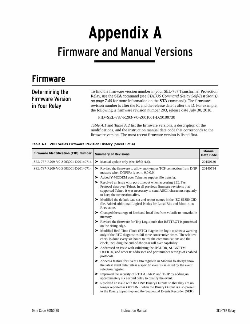
Date Code 20150130 Instruction Manual SEL-787 Relay
Appendix AFirmware and Manual Versions
FirmwareDetermining the Firmware Version in Your Relay
To find the firmware version number in your SEL-787 Transformer Protection Relay, use the STA command (see STATUS Command (Relay Self-Test Status) on page 7.40 for more information on the STA command). The firmware revision number is after the R, and the release date is after the D. For example, the following is firmware revision number 203, release date July 30, 2010.
FID=SEL-787-R203-V0-Z001001-D20100730
Table A.1 and Table A.2 list the firmware versions, a description of the modifications, and the instruction manual date code that corresponds to the firmware version. The most recent firmware version is listed first.
Table A.1 200 Series Firmware Revision History (Sheet 1 of 4)
Firmware Identification (FID) Number Summary of RevisionsManual
Date Code
SEL-787-R209-V0-Z003001-D20140714 ➤ Manual update only (see Table A.6). 20150130
SEL-787-R209-V0-Z003001-D20140714 ➤ Revised the firmware to allow anonymous TCP connection from DNP masters when DNPIPx is set to 0.0.0.0.
➤ Added Y-MODEM over Telnet to support file transfer.
➤ Resolved an issue with port timeout when accessing SEL Fast Protocol data over Telnet. In all previous firmware revisions that supported Telnet, it was necessary to send ASCII characters regularly to keep the connection alive.
➤ Modified the default data set and report names in the IEC 61850 CID file. Added additional Logical Nodes for Local Bits and MIRRORED BITS status.
➤ Changed the storage of latch and local bits from volatile to nonvolatile memory.
➤ Revised the firmware for Trip Logic such that RSTTRGT is processed on the rising edge.
➤ Modified Real Time Clock (RTC) diagnostics logic to show a warning only if the RTC diagnostics fail three consecutive times. The self-test check is done every six hours to test the communications and the clock, including the end-of-the-year roll over capability.
➤ Addressed an issue with validating the IPADDR, SUBNETM, DEFRTR, and other IP addresses and port number settings of enabled protocols.
➤ Added a feature for Event Data registers in Modbus to always show the latest event data unless a specific event is selected by the event selection register.
➤ Improved the security of RTD ALARM and TRIP by adding an approximately six second delay to qualify the event.
➤ Resolved an issue with the DNP Binary Outputs so that they are no longer reported as OFFLINE when the Binary Output is also present in the Binary Input map and the Sequential Events Recorder (SER).
20140714
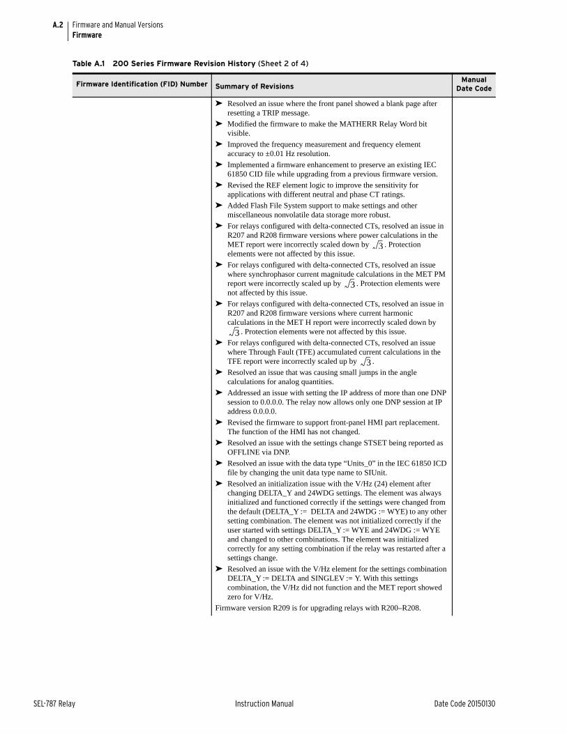
A.2
SEL-787 Relay Instruction Manual Date Code 20150130
Firmware and Manual VersionsFirmware
➤ Resolved an issue where the front panel showed a blank page after resetting a TRIP message.
➤ Modified the firmware to make the MATHERR Relay Word bit visible.
➤ Improved the frequency measurement and frequency element accuracy to ±0.01 Hz resolution.
➤ Implemented a firmware enhancement to preserve an existing IEC 61850 CID file while upgrading from a previous firmware version.
➤ Revised the REF element logic to improve the sensitivity for applications with different neutral and phase CT ratings.
➤ Added Flash File System support to make settings and other miscellaneous nonvolatile data storage more robust.
➤ For relays configured with delta-connected CTs, resolved an issue in R207 and R208 firmware versions where power calculations in the MET report were incorrectly scaled down by . Protection elements were not affected by this issue.
➤ For relays configured with delta-connected CTs, resolved an issue where synchrophasor current magnitude calculations in the MET PM report were incorrectly scaled up by . Protection elements were not affected by this issue.
➤ For relays configured with delta-connected CTs, resolved an issue in R207 and R208 firmware versions where current harmonic calculations in the MET H report were incorrectly scaled down by
. Protection elements were not affected by this issue.
➤ For relays configured with delta-connected CTs, resolved an issue where Through Fault (TFE) accumulated current calculations in the TFE report were incorrectly scaled up by .
➤ Resolved an issue that was causing small jumps in the angle calculations for analog quantities.
➤ Addressed an issue with setting the IP address of more than one DNP session to 0.0.0.0. The relay now allows only one DNP session at IP address 0.0.0.0.
➤ Revised the firmware to support front-panel HMI part replacement. The function of the HMI has not changed.
➤ Resolved an issue with the settings change STSET being reported as OFFLINE via DNP.
➤ Resolved an issue with the data type “Units_0” in the IEC 61850 ICD file by changing the unit data type name to SIUnit.
➤ Resolved an initialization issue with the V/Hz (24) element after changing DELTA_Y and 24WDG settings. The element was always initialized and functioned correctly if the settings were changed from the default (DELTA_Y := DELTA and 24WDG := WYE) to any other setting combination. The element was not initialized correctly if the user started with settings DELTA_Y := WYE and 24WDG := WYE and changed to other combinations. The element was initialized correctly for any setting combination if the relay was restarted after a settings change.
➤ Resolved an issue with the V/Hz element for the settings combination DELTA_Y := DELTA and SINGLEV := Y. With this settings combination, the V/Hz did not function and the MET report showed zero for V/Hz.
Firmware version R209 is for upgrading relays with R200–R208.
Table A.1 200 Series Firmware Revision History (Sheet 2 of 4)
Firmware Identification (FID) Number Summary of RevisionsManual
Date Code
3
3
3
3
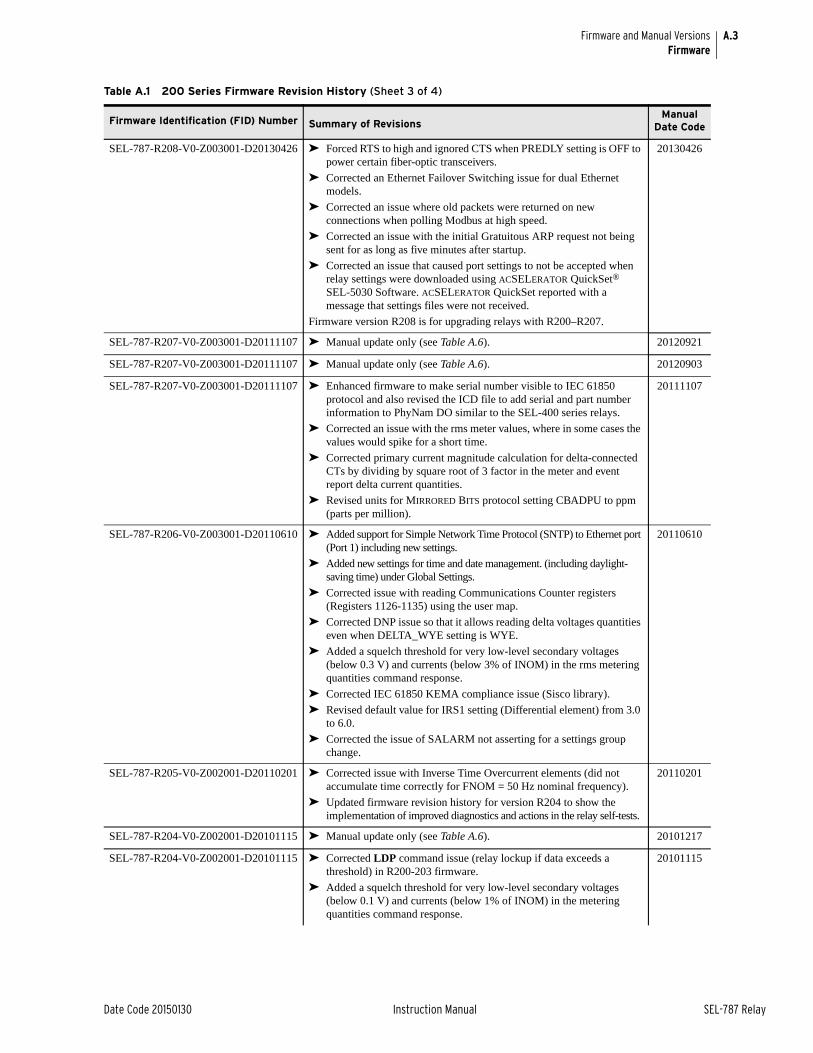
A.3
Date Code 20150130 Instruction Manual SEL-787 Relay
Firmware and Manual VersionsFirmware
SEL-787-R208-V0-Z003001-D20130426 ➤ Forced RTS to high and ignored CTS when PREDLY setting is OFF to power certain fiber-optic transceivers.
➤ Corrected an Ethernet Failover Switching issue for dual Ethernet models.
➤ Corrected an issue where old packets were returned on new connections when polling Modbus at high speed.
➤ Corrected an issue with the initial Gratuitous ARP request not being sent for as long as five minutes after startup.
➤ Corrected an issue that caused port settings to not be accepted when relay settings were downloaded using ACSELERATOR QuickSet® SEL-5030 Software. ACSELERATOR QuickSet reported with a message that settings files were not received.
Firmware version R208 is for upgrading relays with R200–R207.
20130426
SEL-787-R207-V0-Z003001-D20111107 ➤ Manual update only (see Table A.6). 20120921
SEL-787-R207-V0-Z003001-D20111107 ➤ Manual update only (see Table A.6). 20120903
SEL-787-R207-V0-Z003001-D20111107 ➤ Enhanced firmware to make serial number visible to IEC 61850 protocol and also revised the ICD file to add serial and part number information to PhyNam DO similar to the SEL-400 series relays.
➤ Corrected an issue with the rms meter values, where in some cases the values would spike for a short time.
➤ Corrected primary current magnitude calculation for delta-connected CTs by dividing by square root of 3 factor in the meter and event report delta current quantities.
➤ Revised units for MIRRORED BITS protocol setting CBADPU to ppm (parts per million).
20111107
SEL-787-R206-V0-Z003001-D20110610 ➤ Added support for Simple Network Time Protocol (SNTP) to Ethernet port (Port 1) including new settings.
➤ Added new settings for time and date management. (including daylight-saving time) under Global Settings.
➤ Corrected issue with reading Communications Counter registers (Registers 1126-1135) using the user map.
➤ Corrected DNP issue so that it allows reading delta voltages quantities even when DELTA_WYE setting is WYE.
➤ Added a squelch threshold for very low-level secondary voltages (below 0.3 V) and currents (below 3% of INOM) in the rms metering quantities command response.
➤ Corrected IEC 61850 KEMA compliance issue (Sisco library).
➤ Revised default value for IRS1 setting (Differential element) from 3.0 to 6.0.
➤ Corrected the issue of SALARM not asserting for a settings group change.
20110610
SEL-787-R205-V0-Z002001-D20110201 ➤ Corrected issue with Inverse Time Overcurrent elements (did not accumulate time correctly for FNOM = 50 Hz nominal frequency).
➤ Updated firmware revision history for version R204 to show the implementation of improved diagnostics and actions in the relay self-tests.
20110201
SEL-787-R204-V0-Z002001-D20101115 ➤ Manual update only (see Table A.6). 20101217
SEL-787-R204-V0-Z002001-D20101115 ➤ Corrected LDP command issue (relay lockup if data exceeds a threshold) in R200-203 firmware.
➤ Added a squelch threshold for very low-level secondary voltages (below 0.1 V) and currents (below 1% of INOM) in the metering quantities command response.
20101115
Table A.1 200 Series Firmware Revision History (Sheet 3 of 4)
Firmware Identification (FID) Number Summary of RevisionsManual
Date Code
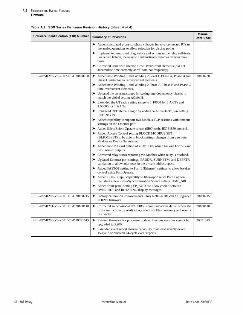
A.4
SEL-787 Relay Instruction Manual Date Code 20150130
Firmware and Manual VersionsFirmware
➤ Added calculated phase-to-phase voltages for wye-connected PTs to the analog quantities to allow selection for display points.
➤ Implemented improved diagnostics and actions in the relay self-tests. For certain failures, the relay will automatically restart as many as three times.
➤ Corrected issue with Inverse Time Overcurrent elements (did not accumulate time correctly at off-nominal frequency).
SEL-787-R203-V0-Z002001-D20100730 ➤ Added new Winding 1 and Winding 2, level 1, Phase A, Phase B and Phase C instantaneous overcurrent elements.
➤ Added new Winding 1 and Winding 2 Phase A, Phase B and Phase C time-overcurrent elements.
➤ Updated the error messages for setting interdependency checks to match the global setting AOx0yH.
➤ Extended the CT ratio setting range to 1:10000 for 5 A CTs and 1:50000 for 1 A CTs.
➤ Enhanced REF element logic by adding 52A interlock (new setting REF52BYP).
➤ Added capability to support two Modbus TCP sessions with timeout settings on the Ethernet port.
➤ Added Select Before Operate control (SBO) to the IEC 61850 protocol.
➤ Added Access Control setting BLOCK MODBUS SET (BLKMBSET) to be able to block settings changes from a remote Modbus or DeviceNet master.
➤ Added new I/O card option of 4 DI/3 DO, which has one Form-B and two Form-C outputs.
➤ Corrected relay status reporting via Modbus when relay is disabled.
➤ Updated Ethernet port settings IPADDR, SUBNETM, and DEFRTR validation to allow addresses in the private address space.
➤ Added FASTOP setting to Port 1 (Ethernet) settings to allow breaker control using Fast Operate.
➤ Added IRIG-B input capability to fiber-optic serial Port 2 option including a new Time-Synchronization Source setting TIME_SRC.
➤ Added front-panel setting FP_AUTO to allow choice between OVERRIDE and ROTATING display messages.
20100730
SEL-787-R202-V0-Z001001-D20100215 ➤ Factory calibration improvements. Only R200–R201 can be upgraded to R202 firmware.
20100215
SEL-787-R201-V0-Z001001-D20100118 ➤ Corrected an occasional IEC 61850 communications defect where the firmware incorrectly reads an opcode from Flash memory and results in a vector.
20100118
SEL-787-R200-V0-Z001001-D20091015 ➤ Revised firmware for processor update. Previous versions cannot be upgraded to R200.
➤ Extended event report storage capability to at least seventy-seven 15-cycle or nineteen 64-cycle event reports.
20091015
Table A.1 200 Series Firmware Revision History (Sheet 4 of 4)
Firmware Identification (FID) Number Summary of RevisionsManual
Date Code

A.5
Date Code 20150130 Instruction Manual SEL-787 Relay
Firmware and Manual VersionsFirmware
Table A.2 100 Series Firmware Revision History (Sheet 1 of 3)
Firmware Identification (FID) Number Summary of RevisionsManual
Date Code
SEL-787-R110-V0-Z002001-D20140714 ➤ Manual update only (see Table A.6). 20150130
SEL-787-R110-V0-Z002001-D20140714 ➤ For relays configured with delta-connected CTs, resolved an issue in R107–R109 firmware versions where power calculations in the MET report were incorrectly scaled down by . Protection elements were not affected by this issue.
➤ Revised the firmware for Trip Logic such that RSTTRGT is processed on the rising edge.
➤ Modified the firmware to make the MATHERR Relay Word bit visible.
➤ Resolved an issue where the front panel showed a blank page after resetting a TRIP message.
➤ Added a feature for Event Data registers in Modbus to always show the latest event data unless a specific event is selected by the event selection register.
➤ For relays configured with delta-connected CTs, resolved an issue in R107–R109 firmware versions where current harmonic calculations in the MET H report were incorrectly scaled down by . Protection elements were not affected by this issue.
➤ For relays configured with delta-connected CTs, resolved an issue where Through Fault (TFE) accumulated current calculations in the TFE report were incorrectly scaled up by .
➤ Addressed an issue with setting the IP address of more than on DNP session to 0.0.0.0. They relay now allows only on DNP session at IP address 0.0.0.0.
➤ Resolved an initialization issue with the V/Hz (24) element after changing DELTA_Y and 24WDG settings. The element was always initialized and functioned correctly if the settings were changed from the default (DELTA_Y := DELTA and 24WDG := WYE) to any other setting combination. The element was not initialized correctly if the user started with settings DELTA_Y := WYE and 24WDG := WYE and changed to other combinations. The element was initialized correctly for any setting combination if the relay was restarted after a settings change.
➤ Resolved an issue with the V/Hz element for the settings combination DELTA_Y := DELTA and SINGLEV := Y. With this settings combination, the V/Hz did not function and the MET report showed zero for V/Hz.
Firmware version R110 is for upgrading relays with R100–R109.
20140714
SEL-787-R109-V0-Z002001-D20130426 ➤ Forced RTS to high and ignored CTS when PREDLY setting is OFF to power certain fiber-optic transceivers.
➤ Corrected an Ethernet Failover Switching issue for dual Ethernet models.
➤ Corrected an issue where old packets were returned on new connections when polling Modbus at high speed.
➤ Corrected an issue with the initial Gratuitous ARP request not being sent for as long as five minutes after startup.
➤ Corrected an issue of missing SER records upon warm start.
➤ Corrected an issue that caused port settings to be rejected when relay settings were downloaded using ACSELERATOR QuickSet® SEL-5030 Software. ACSELERATOR QuickSet reported with a message that settings files were not received.
Firmware version R109 is for upgrading relays with R100–R108.
20130426
3
3
3
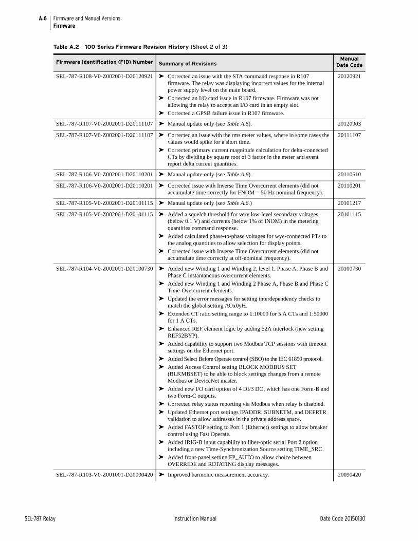
A.6
SEL-787 Relay Instruction Manual Date Code 20150130
Firmware and Manual VersionsFirmware
SEL-787-R108-V0-Z002001-D20120921 ➤ Corrected an issue with the STA command response in R107 firmware. The relay was displaying incorrect values for the internal power supply level on the main board.
➤ Corrected an I/O card issue in R107 firmware. Firmware was not allowing the relay to accept an I/O card in an empty slot.
➤ Corrected a GPSB failure issue in R107 firmware.
20120921
SEL-787-R107-V0-Z002001-D20111107 ➤ Manual update only (see Table A.6). 20120903
SEL-787-R107-V0-Z002001-D20111107 ➤ Corrected an issue with the rms meter values, where in some cases the values would spike for a short time.
➤ Corrected primary current magnitude calculation for delta-connected CTs by dividing by square root of 3 factor in the meter and event report delta current quantities.
20111107
SEL-787-R106-V0-Z002001-D20110201 ➤ Manual update only (see Table A.6). 20110610
SEL-787-R106-V0-Z002001-D20110201 ➤ Corrected issue with Inverse Time Overcurrent elements (did not accumulate time correctly for FNOM = 50 Hz nominal frequency).
20110201
SEL-787-R105-V0-Z002001-D20101115 ➤ Manual update only (see Table A.6.) 20101217
SEL-787-R105-V0-Z002001-D20101115 ➤ Added a squelch threshold for very low-level secondary voltages (below 0.1 V) and currents (below 1% of INOM) in the metering quantities command response.
➤ Added calculated phase-to-phase voltages for wye-connected PTs to the analog quantities to allow selection for display points.
➤ Corrected issue with Inverse Time Overcurrent elements (did not accumulate time correctly at off-nominal frequency).
20101115
SEL-787-R104-V0-Z002001-D20100730 ➤ Added new Winding 1 and Winding 2, level 1, Phase A, Phase B and Phase C instantaneous overcurrent elements.
➤ Added new Winding 1 and Winding 2 Phase A, Phase B and Phase C Time-Overcurrent elements.
➤ Updated the error messages for setting interdependency checks to match the global setting AOx0yH.
➤ Extended CT ratio setting range to 1:10000 for 5 A CTs and 1:50000 for 1 A CTs.
➤ Enhanced REF element logic by adding 52A interlock (new setting REF52BYP).
➤ Added capability to support two Modbus TCP sessions with timeout settings on the Ethernet port.
➤ Added Select Before Operate control (SBO) to the IEC 61850 protocol.
➤ Added Access Control setting BLOCK MODBUS SET (BLKMBSET) to be able to block settings changes from a remote Modbus or DeviceNet master.
➤ Added new I/O card option of 4 DI/3 DO, which has one Form-B and two Form-C outputs.
➤ Corrected relay status reporting via Modbus when relay is disabled.
➤ Updated Ethernet port settings IPADDR, SUBNETM, and DEFRTR validation to allow addresses in the private address space.
➤ Added FASTOP setting to Port 1 (Ethernet) settings to allow breaker control using Fast Operate.
➤ Added IRIG-B input capability to fiber-optic serial Port 2 option including a new Time-Synchronization Source setting TIME_SRC.
➤ Added front-panel setting FP_AUTO to allow choice between OVERRIDE and ROTATING display messages.
20100730
SEL-787-R103-V0-Z001001-D20090420 ➤ Improved harmonic measurement accuracy. 20090420
Table A.2 100 Series Firmware Revision History (Sheet 2 of 3)
Firmware Identification (FID) Number Summary of RevisionsManual
Date Code
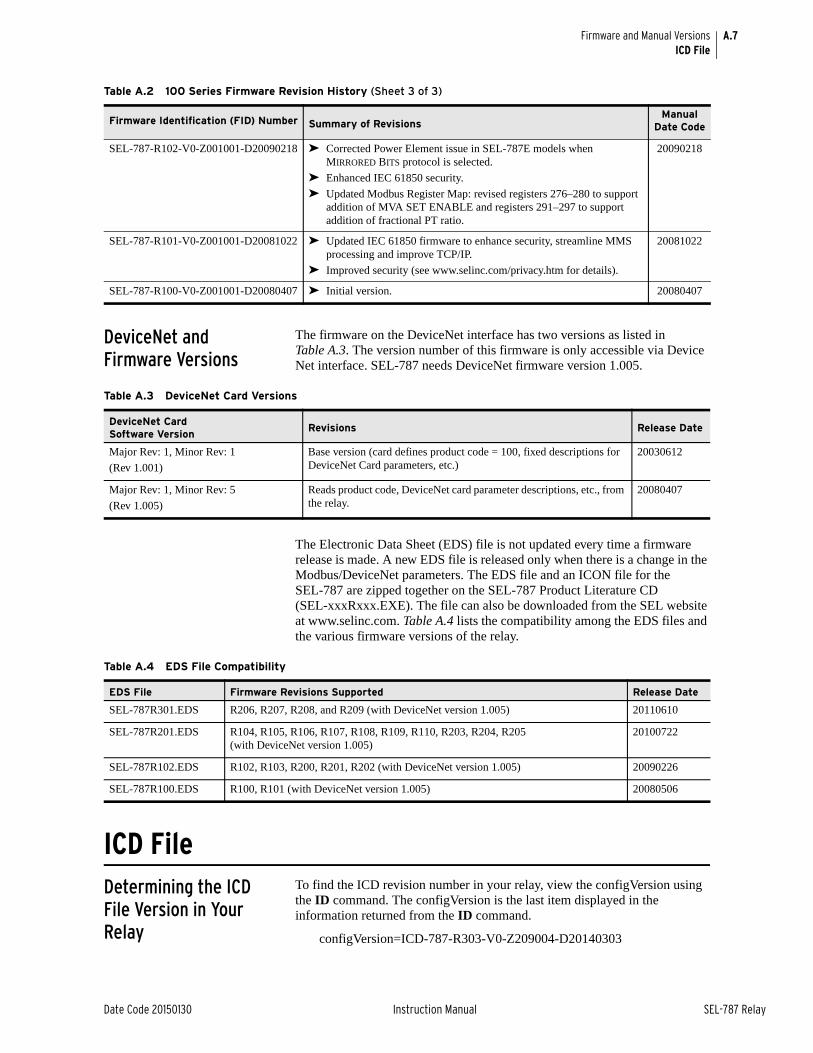
A.7
Date Code 20150130 Instruction Manual SEL-787 Relay
Firmware and Manual VersionsICD File
DeviceNet and Firmware Versions
The firmware on the DeviceNet interface has two versions as listed in Table A.3. The version number of this firmware is only accessible via Device Net interface. SEL-787 needs DeviceNet firmware version 1.005.
The Electronic Data Sheet (EDS) file is not updated every time a firmware release is made. A new EDS file is released only when there is a change in the Modbus/DeviceNet parameters. The EDS file and an ICON file for the SEL-787 are zipped together on the SEL-787 Product Literature CD (SEL-xxxRxxx.EXE). The file can also be downloaded from the SEL website at www.selinc.com. Table A.4 lists the compatibility among the EDS files and the various firmware versions of the relay.
ICD FileDetermining the ICD File Version in Your Relay
To find the ICD revision number in your relay, view the configVersion using the ID command. The configVersion is the last item displayed in the information returned from the ID command.
configVersion=ICD-787-R303-V0-Z209004-D20140303
SEL-787-R102-V0-Z001001-D20090218 ➤ Corrected Power Element issue in SEL-787E models when MIRRORED BITS protocol is selected.
➤ Enhanced IEC 61850 security.
➤ Updated Modbus Register Map: revised registers 276–280 to support addition of MVA SET ENABLE and registers 291–297 to support addition of fractional PT ratio.
20090218
SEL-787-R101-V0-Z001001-D20081022 ➤ Updated IEC 61850 firmware to enhance security, streamline MMS processing and improve TCP/IP.
➤ Improved security (see www.selinc.com/privacy.htm for details).
20081022
SEL-787-R100-V0-Z001001-D20080407 ➤ Initial version. 20080407
Table A.2 100 Series Firmware Revision History (Sheet 3 of 3)
Firmware Identification (FID) Number Summary of RevisionsManual
Date Code
Table A.3 DeviceNet Card Versions
DeviceNet Card Software Version
Revisions Release Date
Major Rev: 1, Minor Rev: 1
(Rev 1.001)
Base version (card defines product code = 100, fixed descriptions for DeviceNet Card parameters, etc.)
20030612
Major Rev: 1, Minor Rev: 5
(Rev 1.005)
Reads product code, DeviceNet card parameter descriptions, etc., from the relay.
20080407
Table A.4 EDS File Compatibility
EDS File Firmware Revisions Supported Release Date
SEL-787R301.EDS R206, R207, R208, and R209 (with DeviceNet version 1.005) 20110610
SEL-787R201.EDS R104, R105, R106, R107, R108, R109, R110, R203, R204, R205 (with DeviceNet version 1.005)
20100722
SEL-787R102.EDS R102, R103, R200, R201, R202 (with DeviceNet version 1.005) 20090226
SEL-787R100.EDS R100, R101 (with DeviceNet version 1.005) 20080506
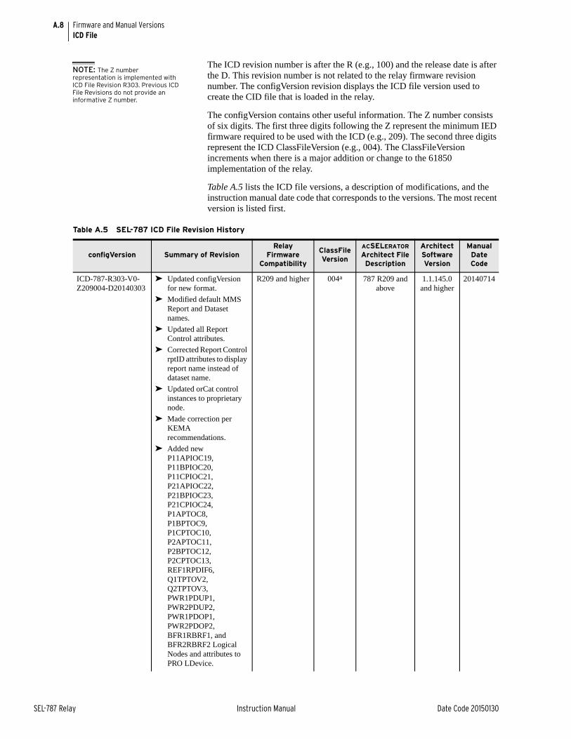
A.8
SEL-787 Relay Instruction Manual Date Code 20150130
Firmware and Manual VersionsICD File
The ICD revision number is after the R (e.g., 100) and the release date is after the D. This revision number is not related to the relay firmware revision number. The configVersion revision displays the ICD file version used to create the CID file that is loaded in the relay.
The configVersion contains other useful information. The Z number consists of six digits. The first three digits following the Z represent the minimum IED firmware required to be used with the ICD (e.g., 209). The second three digits represent the ICD ClassFileVersion (e.g., 004). The ClassFileVersion increments when there is a major addition or change to the 61850 implementation of the relay.
Table A.5 lists the ICD file versions, a description of modifications, and the instruction manual date code that corresponds to the versions. The most recent version is listed first.
NOTE: The Z number representation is implemented with ICD File Revision R303. Previous ICD File Revisions do not provide an informative Z number.
Table A.5 SEL-787 ICD File Revision History
configVersion Summary of RevisionRelay
Firmware Compatibility
ClassFile Version
ACSELERATOR Architect File Description
Architect Software Version
Manual Date Code
ICD-787-R303-V0-Z209004-D20140303
➤ Updated configVersion for new format.
➤ Modified default MMS Report and Dataset names.
➤ Updated all Report Control attributes.
➤ Corrected Report Control rptID attributes to display report name instead of dataset name.
➤ Updated orCat control instances to proprietary node.
➤ Made correction per KEMA recommendations.
➤ Added new P11APIOC19, P11BPIOC20, P11CPIOC21, P21APIOC22, P21BPIOC23, P21CPIOC24, P1APTOC8, P1BPTOC9, P1CPTOC10, P2APTOC11, P2BPTOC12, P2CPTOC13, REF1RPDIF6, Q1TPTOV2, Q2TPTOV3, PWR1PDUP1, PWR2PDUP2, PWR1PDOP1, PWR2PDOP2, BFR1RBRF1, and BFR2RBRF2 Logical Nodes and attributes to PRO LDevice.
R209 and higher 004a 787 R209 and above
1.1.145.0 and higher
20140714
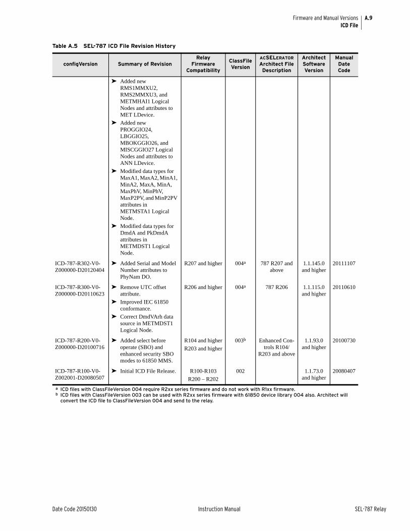
A.9
Date Code 20150130 Instruction Manual SEL-787 Relay
Firmware and Manual VersionsICD File
➤ Added new RMS1MMXU2, RMS2MMXU3, and METMHAI1 Logical Nodes and attributes to MET LDevice.
➤ Added new PROGGIO24, LBGGIO25, MBOKGGIO26, and MISCGGIO27 Logical Nodes and attributes to ANN LDevice.
➤ Modified data types for MaxA1, MaxA2, MinA1, MinA2, MaxA, MinA, MaxPhV, MinPhV, MaxP2PV, and MinP2PV attributes in METMSTA1 Logical Node.
➤ Modified data types for DmdA and PkDmdA attributes in METMDST1 Logical Node.
ICD-787-R302-V0-Z000000-D20120404
➤ Added Serial and Model Number attributes to PhyNam DO.
R207 and higher 004a 787 R207 and above
1.1.145.0 and higher
20111107
ICD-787-R300-V0-Z000000-D20110623
➤ Remove UTC offset attribute.
➤ Improved IEC 61850 conformance.
➤ Correct DmdVArh data source in METMDST1 Logical Node.
R206 and higher 004a 787 R206 1.1.115.0 and higher
20110610
ICD-787-R200-V0-Z000000-D20100716
➤ Added select before operate (SBO) and enhanced security SBO modes to 61850 MMS.
R104 and higher
R203 and higher
003b Enhanced Con-trols R104/
R203 and above
1.1.93.0 and higher
20100730
ICD-787-R100-V0-Z002001-D20080507
➤ Initial ICD File Release. R100-R103
R200 – R202
002 1.1.73.0 and higher
20080407
a ICD files with ClassFileVersion 004 require R2xx series firmware and do not work with R1xx firmware.b ICD files with ClassFileVersion 003 can be used with R2xx series firmware with 61850 device library 004 also. Architect will
convert the ICD file to ClassFileVersion 004 and send to the relay.
Table A.5 SEL-787 ICD File Revision History
configVersion Summary of RevisionRelay
Firmware Compatibility
ClassFile Version
ACSELERATOR Architect File Description
Architect Software Version
Manual Date Code
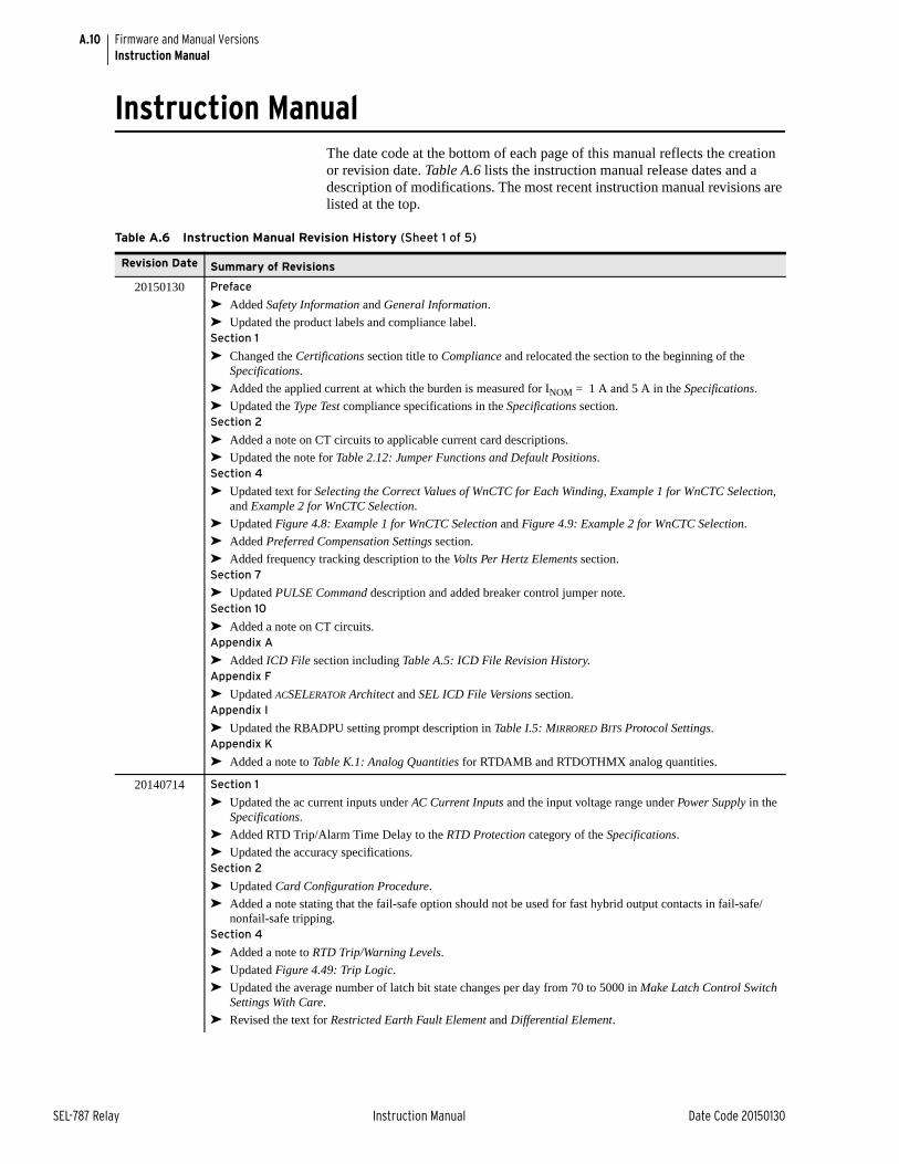
A.10
SEL-787 Relay Instruction Manual Date Code 20150130
Firmware and Manual VersionsInstruction Manual
Instruction ManualThe date code at the bottom of each page of this manual reflects the creation or revision date. Table A.6 lists the instruction manual release dates and a description of modifications. The most recent instruction manual revisions are listed at the top.
Table A.6 Instruction Manual Revision History (Sheet 1 of 5)
Revision Date Summary of Revisions
20150130 Preface
➤ Added Safety Information and General Information.
➤ Updated the product labels and compliance label.Section 1
➤ Changed the Certifications section title to Compliance and relocated the section to the beginning of the Specifications.
➤ Added the applied current at which the burden is measured for INOM = 1 A and 5 A in the Specifications.
➤ Updated the Type Test compliance specifications in the Specifications section.Section 2
➤ Added a note on CT circuits to applicable current card descriptions.
➤ Updated the note for Table 2.12: Jumper Functions and Default Positions.Section 4
➤ Updated text for Selecting the Correct Values of WnCTC for Each Winding, Example 1 for WnCTC Selection, and Example 2 for WnCTC Selection.
➤ Updated Figure 4.8: Example 1 for WnCTC Selection and Figure 4.9: Example 2 for WnCTC Selection.
➤ Added Preferred Compensation Settings section.
➤ Added frequency tracking description to the Volts Per Hertz Elements section.Section 7
➤ Updated PULSE Command description and added breaker control jumper note.Section 10
➤ Added a note on CT circuits.Appendix A
➤ Added ICD File section including Table A.5: ICD File Revision History.Appendix F
➤ Updated ACSELERATOR Architect and SEL ICD File Versions section.Appendix I
➤ Updated the RBADPU setting prompt description in Table I.5: MIRRORED BITS Protocol Settings.Appendix K
➤ Added a note to Table K.1: Analog Quantities for RTDAMB and RTDOTHMX analog quantities.
20140714 Section 1
➤ Updated the ac current inputs under AC Current Inputs and the input voltage range under Power Supply in the Specifications.
➤ Added RTD Trip/Alarm Time Delay to the RTD Protection category of the Specifications.
➤ Updated the accuracy specifications.Section 2
➤ Updated Card Configuration Procedure.
➤ Added a note stating that the fail-safe option should not be used for fast hybrid output contacts in fail-safe/nonfail-safe tripping.
Section 4
➤ Added a note to RTD Trip/Warning Levels.
➤ Updated Figure 4.49: Trip Logic.
➤ Updated the average number of latch bit state changes per day from 70 to 5000 in Make Latch Control Switch Settings With Care.
➤ Revised the text for Restricted Earth Fault Element and Differential Element.
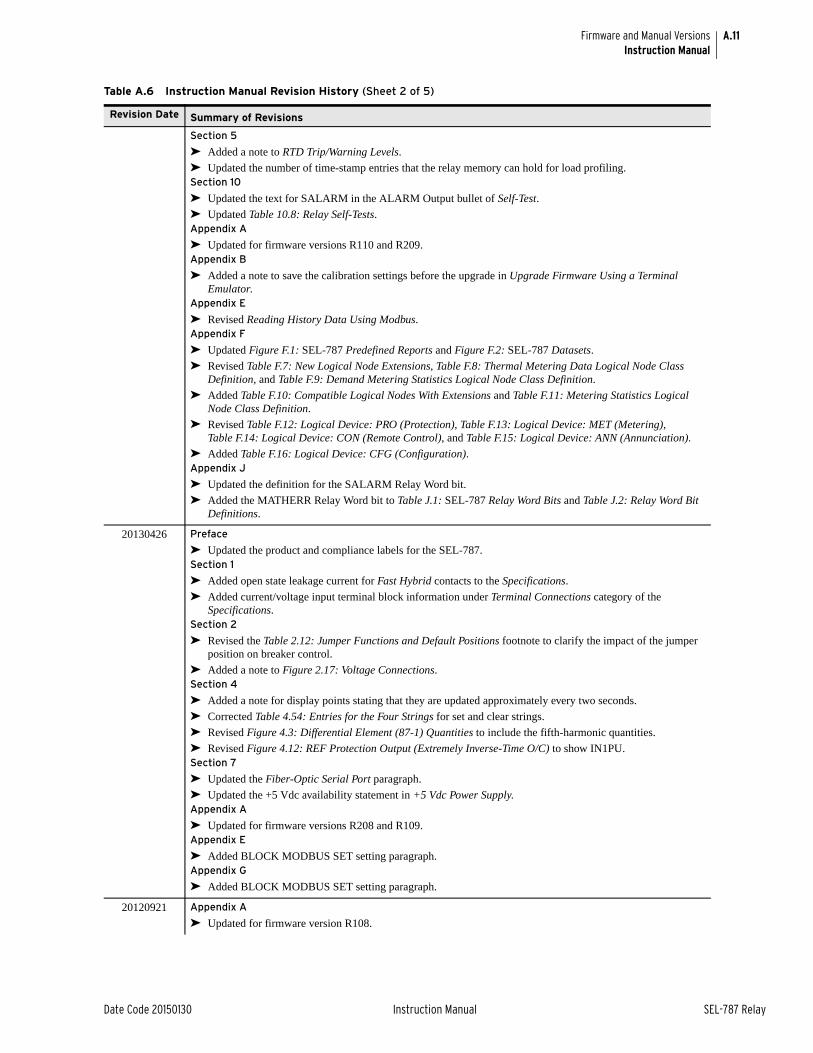
A.11
Date Code 20150130 Instruction Manual SEL-787 Relay
Firmware and Manual VersionsInstruction Manual
Section 5
➤ Added a note to RTD Trip/Warning Levels.
➤ Updated the number of time-stamp entries that the relay memory can hold for load profiling.Section 10
➤ Updated the text for SALARM in the ALARM Output bullet of Self-Test.
➤ Updated Table 10.8: Relay Self-Tests.Appendix A
➤ Updated for firmware versions R110 and R209.Appendix B
➤ Added a note to save the calibration settings before the upgrade in Upgrade Firmware Using a Terminal Emulator.
Appendix E
➤ Revised Reading History Data Using Modbus.Appendix F
➤ Updated Figure F.1: SEL-787 Predefined Reports and Figure F.2: SEL-787 Datasets.
➤ Revised Table F.7: New Logical Node Extensions, Table F.8: Thermal Metering Data Logical Node Class Definition, and Table F.9: Demand Metering Statistics Logical Node Class Definition.
➤ Added Table F.10: Compatible Logical Nodes With Extensions and Table F.11: Metering Statistics Logical Node Class Definition.
➤ Revised Table F.12: Logical Device: PRO (Protection), Table F.13: Logical Device: MET (Metering), Table F.14: Logical Device: CON (Remote Control), and Table F.15: Logical Device: ANN (Annunciation).
➤ Added Table F.16: Logical Device: CFG (Configuration).Appendix J
➤ Updated the definition for the SALARM Relay Word bit.
➤ Added the MATHERR Relay Word bit to Table J.1: SEL-787 Relay Word Bits and Table J.2: Relay Word Bit Definitions.
20130426 Preface
➤ Updated the product and compliance labels for the SEL-787.Section 1
➤ Added open state leakage current for Fast Hybrid contacts to the Specifications.
➤ Added current/voltage input terminal block information under Terminal Connections category of the Specifications.
Section 2
➤ Revised the Table 2.12: Jumper Functions and Default Positions footnote to clarify the impact of the jumper position on breaker control.
➤ Added a note to Figure 2.17: Voltage Connections.Section 4
➤ Added a note for display points stating that they are updated approximately every two seconds.
➤ Corrected Table 4.54: Entries for the Four Strings for set and clear strings.
➤ Revised Figure 4.3: Differential Element (87-1) Quantities to include the fifth-harmonic quantities.
➤ Revised Figure 4.12: REF Protection Output (Extremely Inverse-Time O/C) to show IN1PU.Section 7
➤ Updated the Fiber-Optic Serial Port paragraph.
➤ Updated the +5 Vdc availability statement in +5 Vdc Power Supply.Appendix A
➤ Updated for firmware versions R208 and R109.Appendix E
➤ Added BLOCK MODBUS SET setting paragraph.Appendix G
➤ Added BLOCK MODBUS SET setting paragraph.
20120921 Appendix A
➤ Updated for firmware version R108.
Table A.6 Instruction Manual Revision History (Sheet 2 of 5)
Revision Date Summary of Revisions
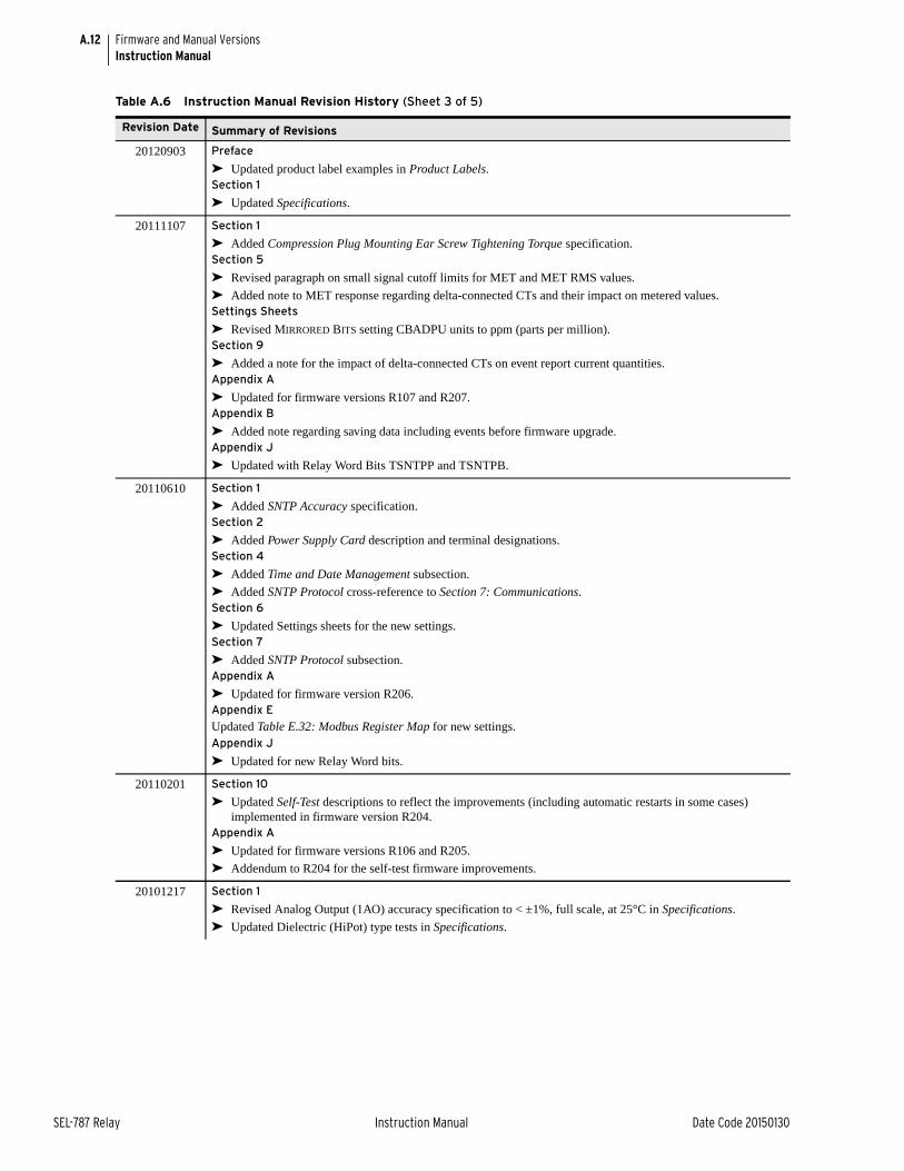
A.12
SEL-787 Relay Instruction Manual Date Code 20150130
Firmware and Manual VersionsInstruction Manual
20120903 Preface
➤ Updated product label examples in Product Labels.Section 1
➤ Updated Specifications.
20111107 Section 1
➤ Added Compression Plug Mounting Ear Screw Tightening Torque specification.Section 5
➤ Revised paragraph on small signal cutoff limits for MET and MET RMS values.
➤ Added note to MET response regarding delta-connected CTs and their impact on metered values.Settings Sheets
➤ Revised MIRRORED BITS setting CBADPU units to ppm (parts per million).Section 9
➤ Added a note for the impact of delta-connected CTs on event report current quantities.Appendix A
➤ Updated for firmware versions R107 and R207.Appendix B
➤ Added note regarding saving data including events before firmware upgrade.Appendix J
➤ Updated with Relay Word Bits TSNTPP and TSNTPB.
20110610 Section 1
➤ Added SNTP Accuracy specification.Section 2
➤ Added Power Supply Card description and terminal designations.Section 4
➤ Added Time and Date Management subsection.
➤ Added SNTP Protocol cross-reference to Section 7: Communications.Section 6
➤ Updated Settings sheets for the new settings.Section 7
➤ Added SNTP Protocol subsection.Appendix A
➤ Updated for firmware version R206.Appendix E
Updated Table E.32: Modbus Register Map for new settings.Appendix J
➤ Updated for new Relay Word bits.
20110201 Section 10
➤ Updated Self-Test descriptions to reflect the improvements (including automatic restarts in some cases) implemented in firmware version R204.
Appendix A
➤ Updated for firmware versions R106 and R205.
➤ Addendum to R204 for the self-test firmware improvements.
20101217 Section 1
➤ Revised Analog Output (1AO) accuracy specification to < ±1%, full scale, at 25°C in Specifications.
➤ Updated Dielectric (HiPot) type tests in Specifications.
Table A.6 Instruction Manual Revision History (Sheet 3 of 5)
Revision Date Summary of Revisions
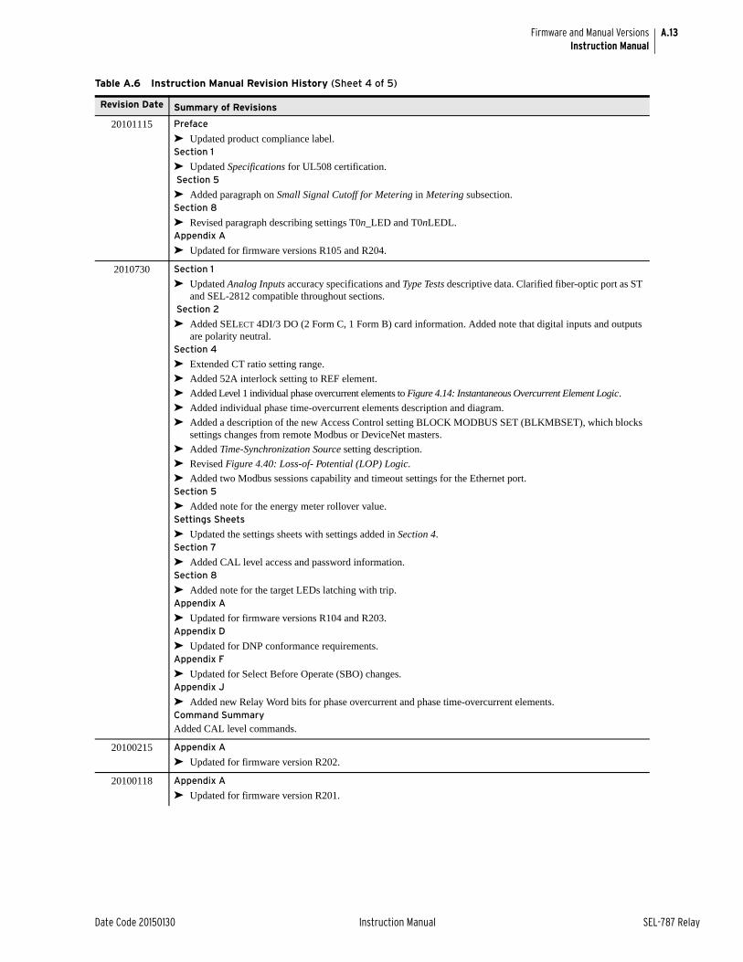
A.13
Date Code 20150130 Instruction Manual SEL-787 Relay
Firmware and Manual VersionsInstruction Manual
20101115 Preface
➤ Updated product compliance label.Section 1
➤ Updated Specifications for UL508 certification. Section 5
➤ Added paragraph on Small Signal Cutoff for Metering in Metering subsection.Section 8
➤ Revised paragraph describing settings T0n_LED and T0nLEDL.Appendix A
➤ Updated for firmware versions R105 and R204.
2010730 Section 1
➤ Updated Analog Inputs accuracy specifications and Type Tests descriptive data. Clarified fiber-optic port as ST and SEL-2812 compatible throughout sections.
Section 2
➤ Added SELECT 4DI/3 DO (2 Form C, 1 Form B) card information. Added note that digital inputs and outputs are polarity neutral.
Section 4
➤ Extended CT ratio setting range.
➤ Added 52A interlock setting to REF element.
➤ Added Level 1 individual phase overcurrent elements to Figure 4.14: Instantaneous Overcurrent Element Logic.
➤ Added individual phase time-overcurrent elements description and diagram.
➤ Added a description of the new Access Control setting BLOCK MODBUS SET (BLKMBSET), which blocks settings changes from remote Modbus or DeviceNet masters.
➤ Added Time-Synchronization Source setting description.
➤ Revised Figure 4.40: Loss-of- Potential (LOP) Logic.
➤ Added two Modbus sessions capability and timeout settings for the Ethernet port.Section 5
➤ Added note for the energy meter rollover value.Settings Sheets
➤ Updated the settings sheets with settings added in Section 4.Section 7
➤ Added CAL level access and password information.Section 8
➤ Added note for the target LEDs latching with trip.Appendix A
➤ Updated for firmware versions R104 and R203.Appendix D
➤ Updated for DNP conformance requirements.Appendix F
➤ Updated for Select Before Operate (SBO) changes.Appendix J
➤ Added new Relay Word bits for phase overcurrent and phase time-overcurrent elements.Command Summary
Added CAL level commands.
20100215 Appendix A
➤ Updated for firmware version R202.
20100118 Appendix A
➤ Updated for firmware version R201.
Table A.6 Instruction Manual Revision History (Sheet 4 of 5)
Revision Date Summary of Revisions
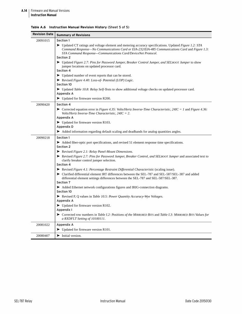
A.14
SEL-787 Relay Instruction Manual Date Code 20150130
Firmware and Manual VersionsInstruction Manual
20091015 Section 1
➤ Updated CT ratings and voltage element and metering accuracy specifications. Updated Figure 1.2: STA Command Response—No Communications Card or EIA-232/EIA-485 Communications Card and Figure 1.3: STA Command Response—Communications Card/DeviceNet Protocol.
Section 2
➤ Updated Figure 2.7: Pins for Password Jumper, Breaker Control Jumper, and SELBOOT Jumper to show jumper locations on updated processor card.
Section 4
➤ Updated number of event reports that can be stored.
➤ Revised Figure 4.40: Loss-of- Potential (LOP) Logic.Section 10
➤ Updated Table 10.8: Relay Self-Tests to show additional voltage checks on updated processor card.Appendix A
➤ Updated for firmware version R200.
20090420 Section 4
➤ Corrected equation error in Figure 4.35: Volts/Hertz Inverse-Time Characteristic, 24IC = 1 and Figure 4.36: Volts/Hertz Inverse-Time Characteristic, 24IC = 2.
Appendix A
➤ Updated for firmware version R103.Appendix D
➤ Added information regarding default scaling and deadbands for analog quantities angles.
20090218 Section 1
➤ Added fiber-optic port specifications, and revised 51 element response time specifications.Section 2
➤ Revised Figure 2.1: Relay Panel-Mount Dimensions.
➤ Revised Figure 2.7: Pins for Password Jumper, Breaker Control, and SELBOOT Jumper and associated text to clarify breaker control jumper selection.
Section 4
➤ Revised Figure 4.1: Percentage Restraint Differential Characteristic (scaling issue).
➤ Clarified differential element IRT differences between the SEL-787 and SEL-587/SEL-387 and added differential element settings differences between the SEL-787 and SEL-587/SEL-387.
Section 7
➤ Added Ethernet network configurations figures and IRIG-connection diagrams.Section 10
➤ Revised P, Q values in Table 10.5: Power Quantity Accuracy-Wye Voltages.Appendix A
➤ Updated for firmware version R102.Appendix I
➤ Corrected row numbers in Table I.2: Positions of the MIRRORED BITS and Table I.3: MIRRORED BITS Values for a RXDFLT Setting of 10100111.
20081022 Appendix A
➤ Updated for firmware version R101.
20080407 ➤ Initial version.
Table A.6 Instruction Manual Revision History (Sheet 5 of 5)
Revision Date Summary of Revisions
Date Code 20150130 Instruction Manual SEL-787 Relay
Appendix BFirmware Upgrade Instructions
Instruction Manual
OverviewThese firmware upgrade instructions apply to all SEL-700 series industrial products except the SEL-701 Relay and SEL-734 Meter.
SEL occasionally offers firmware upgrades to improve the performance of your relay. Because the SEL-787 relays store firmware in flash memory, changing physical components is not necessary. Upgrade the relay firmware by downloading a file from a personal computer to the relay via the front-panel serial port via ACSELERATOR QuickSet or terminal emulator as outlined in the following sections. For relays with IEC 61850 option, verify IEC 61850 protocol after the upgrade (see Relays With IEC 61850 Option).
Required Equipment Gather the following equipment before starting this firmware upgrade:
➤ Personal computer (PC)
➤ Terminal emulation software that supports Xmodem/CRC or 1k Xmodem/CRC protocol
➤ Serial communications cable (SEL Cable C234A or equivalent, or a null-modem cable)
➤ Disk containing the firmware upgrade file (for example, r1017xxx.s19 or r1017xxx.z19)
➤ ACSELERATOR QuickSet Software
NOTE: Firmware releases are also available as zip files (.z19). Use the zip file for faster download.
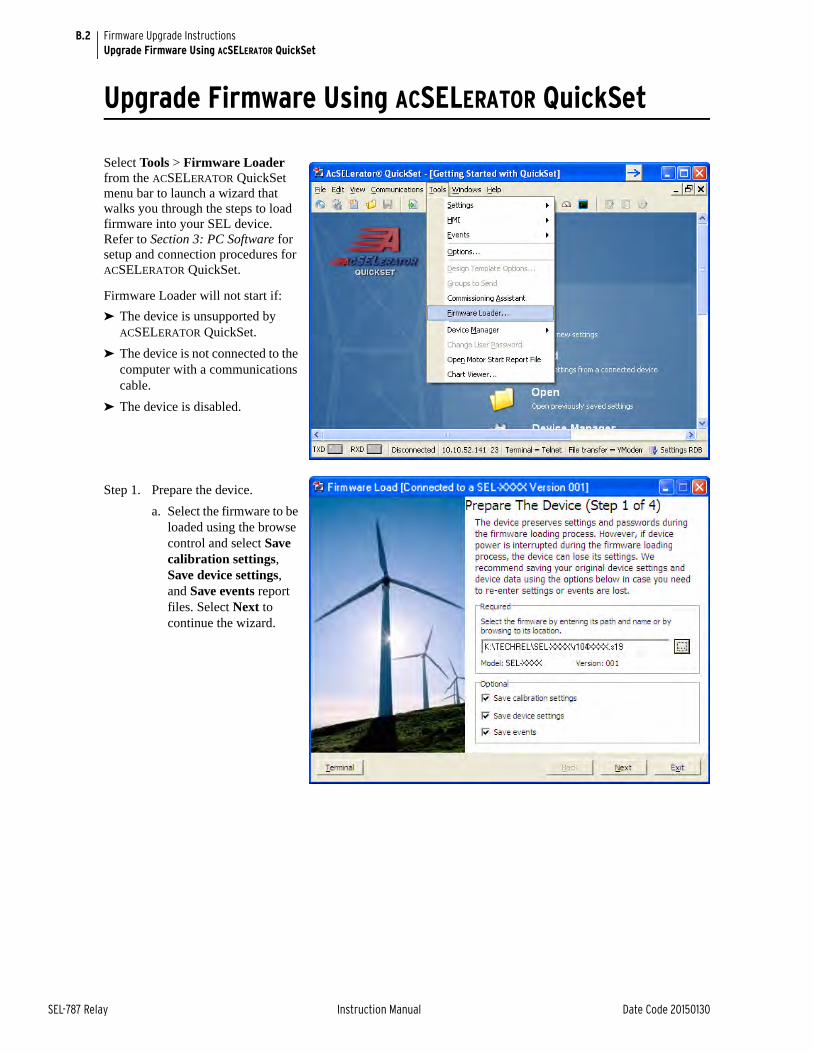
B.2
SEL-787 Relay Instruction Manual Date Code 20150130
Firmware Upgrade InstructionsUpgrade Firmware Using ACSELERATOR QuickSet
Upgrade Firmware Using ACSELERATOR QuickSet
Select Tools > Firmware Loader from the ACSELERATOR QuickSet menu bar to launch a wizard that walks you through the steps to load firmware into your SEL device. Refer to Section 3: PC Software for setup and connection procedures for ACSELERATOR QuickSet.
Firmware Loader will not start if:
➤ The device is unsupported by ACSELERATOR QuickSet.
➤ The device is not connected to the computer with a communications cable.
➤ The device is disabled.
Step 1. Prepare the device.
a. Select the firmware to be loaded using the browse control and select Save calibration settings, Save device settings, and Save events report files. Select Next to continue the wizard.
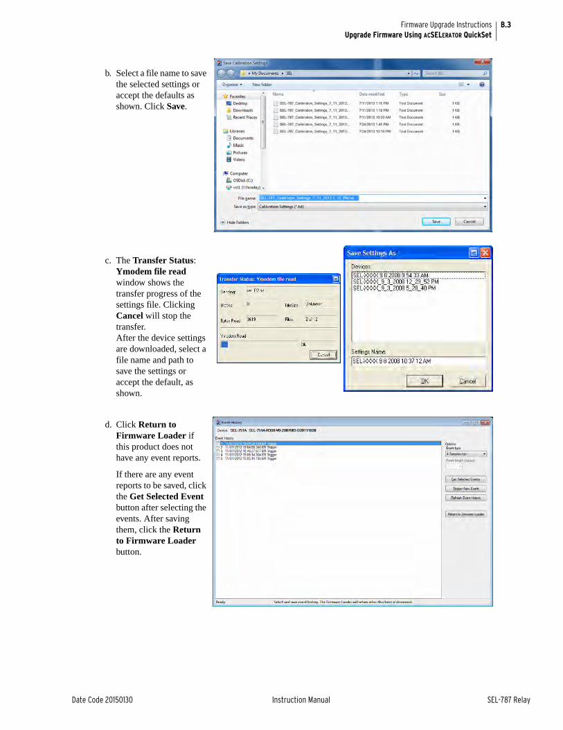
B.3
Date Code 20150130 Instruction Manual SEL-787 Relay
Firmware Upgrade InstructionsUpgrade Firmware Using ACSELERATOR QuickSet
b. Select a file name to save the selected settings or accept the defaults as shown. Click Save.
c. The Transfer Status: Ymodem file read window shows the transfer progress of the settings file. Clicking Cancel will stop the transfer. After the device settings are downloaded, select a file name and path to save the settings or accept the default, as shown.
d. Click Return to Firmware Loader if this product does not have any event reports.
If there are any event reports to be saved, click the Get Selected Event button after selecting the events. After saving them, click the Return to Firmware Loader button.
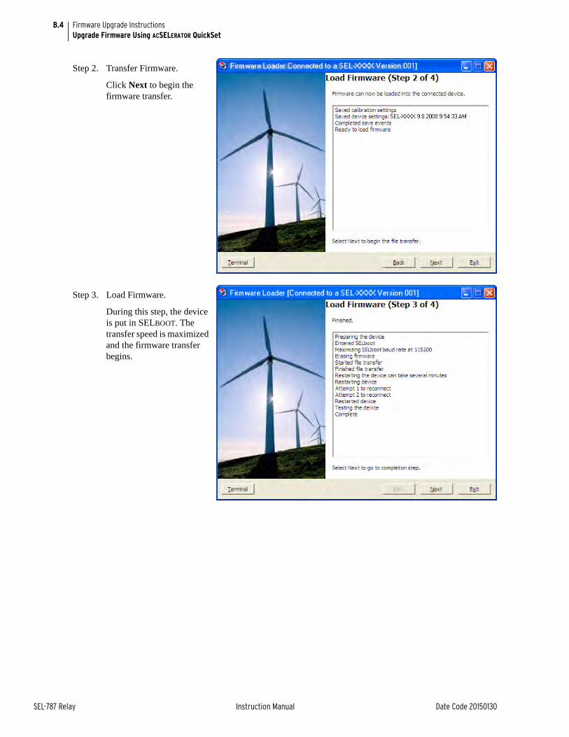
B.4
SEL-787 Relay Instruction Manual Date Code 20150130
Firmware Upgrade InstructionsUpgrade Firmware Using ACSELERATOR QuickSet
Step 2. Transfer Firmware.
Click Next to begin the firmware transfer.
Step 3. Load Firmware.
During this step, the device is put in SELBOOT. The transfer speed is maximized and the firmware transfer begins.
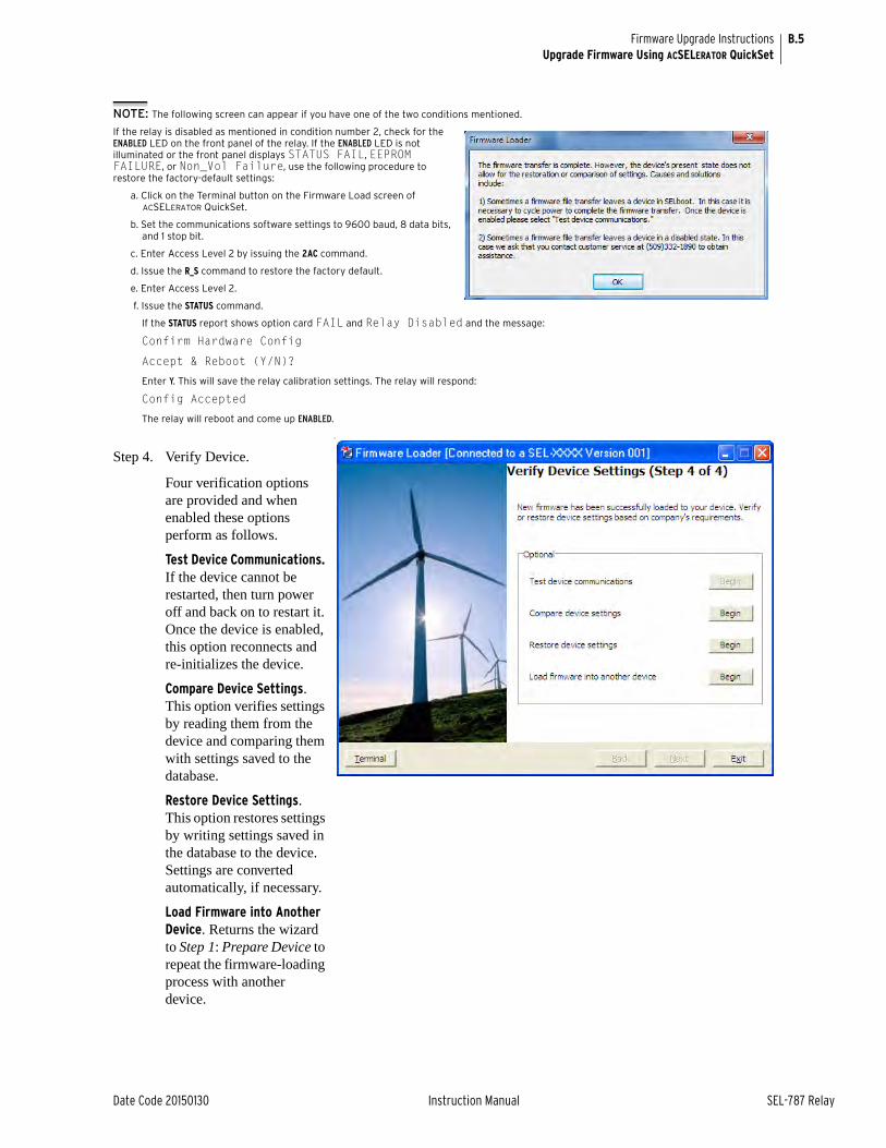
B.5
Date Code 20150130 Instruction Manual SEL-787 Relay
Firmware Upgrade InstructionsUpgrade Firmware Using ACSELERATOR QuickSet
NOTE: The following screen can appear if you have one of the two conditions mentioned.
If the relay is disabled as mentioned in condition number 2, check for the ENABLED LED on the front panel of the relay. If the ENABLED LED is not illuminated or the front panel displays STATUS FAIL, EEPROM FAILURE, or Non_Vol Failure, use the following procedure to restore the factory-default settings:
a. Click on the Terminal button on the Firmware Load screen of ACSELERATOR QuickSet.
b. Set the communications software settings to 9600 baud, 8 data bits, and 1 stop bit.
c. Enter Access Level 2 by issuing the 2AC command.
d. Issue the R_S command to restore the factory default.
e. Enter Access Level 2.
f. Issue the STATUS command.
If the STATUS report shows option card FAIL and Relay Disabled and the message:
Confirm Hardware Config
Accept & Reboot (Y/N)?
Enter Y. This will save the relay calibration settings. The relay will respond:
Config Accepted
The relay will reboot and come up ENABLED.
Step 4. Verify Device.
Four verification options are provided and when enabled these options perform as follows.
Test Device Communications. If the device cannot be restarted, then turn power off and back on to restart it. Once the device is enabled, this option reconnects and re-initializes the device.
Compare Device Settings. This option verifies settings by reading them from the device and comparing them with settings saved to the database.
Restore Device Settings. This option restores settings by writing settings saved in the database to the device. Settings are converted automatically, if necessary.
Load Firmware into Another Device. Returns the wizard to Step 1: Prepare Device to repeat the firmware-loading process with another device.
T

B.6
SEL-787 Relay Instruction Manual Date Code 20150130
Firmware Upgrade InstructionsUpgrade Firmware Using a Terminal Emulator
Upgrade Firmware Using a Terminal EmulatorThe following instructions assume you have a working knowledge of your personal computer terminal emulation software. In particular, you must be able to modify your serial communications parameters (baud rate, data bits, parity, etc.), select transfer protocol (Xmodem/CRC or 1k Xmodem/CRC), and transfer files (for example, send and receive binary files).
Step 1. If the relay is in service, open the relay control circuits.
Step 2. Connect the PC to the front-panel serial port and enter Access Level 2.
Step 3. Save the present relay settings.
You can use the PC software (described in the instruction manual PC software section) to save and restore settings easily. Otherwise, use the following steps.
a. Issue the following commands at the ASCII prompt:
SHO, SHO L, SHO G, SHO P, SHO F, SHO R, SHO C, etc.
b. Record all the settings for possible re-entry after the firmware upgrade.
c. We recommend that you save all stored data in the relay, including EVENTS, before the upgrade.
Step 4. Start upgrading of firmware.
a. Issue the L_D command to the relay.
b. Type Y <Enter> at the following prompt:Disable relay to receive firmware (Y/N)?
c. Type Y <Enter> at the following prompt:Are you sure (Y,N)?
The relay will send the !> prompt.
Step 5. Change the baud rate, if necessary.
a. Type BAU 115200 <Enter>.
This will change the baud rate of the communications port to 115200.
b. Change the baud rate of the PC to 115200 to match the relay.
Step 6. Begin the transfer of new firmware to the relay by issuing the REC command.
Step 7. Type Y to erase the existing firmware or press <Enter> to abort.
Step 8. Press any key (for example, <Enter>) when the relay sends a prompt.
NOTE: To save the calibration settings, perform SHO C from the terminal by logging into the CAL level using the CAL level password. The factory-default password for the CAL level is CLARKE.
NOTE: If you have difficulty at 115200 bps, choose a slower data transfer rate (for example, 38400 bps or 57600 bps). Be sure to match the relay and PC data rates.
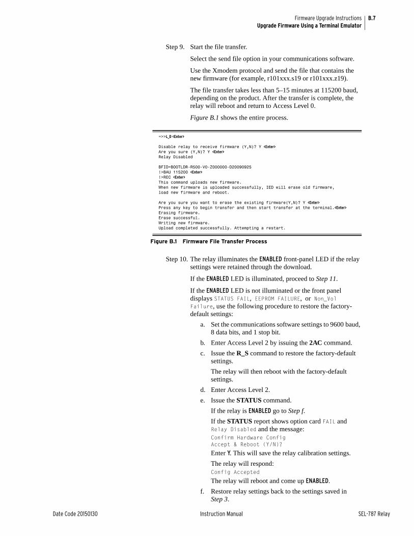
B.7
Date Code 20150130 Instruction Manual SEL-787 Relay
Firmware Upgrade InstructionsUpgrade Firmware Using a Terminal Emulator
Step 9. Start the file transfer.
Select the send file option in your communications software.
Use the Xmodem protocol and send the file that contains the new firmware (for example, r101xxx.s19 or r101xxx.z19).
The file transfer takes less than 5–15 minutes at 115200 baud, depending on the product. After the transfer is complete, the relay will reboot and return to Access Level 0.
Figure B.1 shows the entire process.
Step 10. The relay illuminates the ENABLED front-panel LED if the relay settings were retained through the download.
If the ENABLED LED is illuminated, proceed to Step 11.
If the ENABLED LED is not illuminated or the front panel displays STATUS FAIL, EEPROM FAILURE, or Non_Vol Failure, use the following procedure to restore the factory-default settings:
a. Set the communications software settings to 9600 baud, 8 data bits, and 1 stop bit.
b. Enter Access Level 2 by issuing the 2AC command.
c. Issue the R_S command to restore the factory-default settings.
The relay will then reboot with the factory-default settings.
d. Enter Access Level 2.
e. Issue the STATUS command.
If the relay is ENABLED go to Step f.
If the STATUS report shows option card FAIL and Relay Disabled and the message:Confirm Hardware Config Accept & Reboot (Y/N)?
Enter Y. This will save the relay calibration settings.
The relay will respond:Config Accepted
The relay will reboot and come up ENABLED.
f. Restore relay settings back to the settings saved in Step 3.
=>>L_D <Enter>
Disable relay to receive firmware (Y,N)? Y <Enter>Are you sure (Y,N)? Y <Enter>Relay Disabled
BFID=BOOTLDR-R500-V0-Z000000-D20090925!>BAU 115200 <Enter>!>REC <Enter>This command uploads new firmware.When new firmware is uploaded successfully, IED will erase old firmware,load new firmware and reboot.
Are you sure you want to erase the existing firmware(Y,N)? Y <Enter>Press any key to begin transfer and then start transfer at the terminal.<Enter>Erasing firmware.Erase successful.Writing new firmware.Upload completed successfully. Attempting a restart.
Figure B.1 Firmware File Transfer Process
B.8
SEL-787 Relay Instruction Manual Date Code 20150130
Firmware Upgrade InstructionsRelays With IEC 61850 Option
Step 11. Change the baud rate of the PC to match that of the relay prior to Step 5, and enter Access Level 2.
Step 12. Issue the STATUS command; verify all relay self-test results are OK.
Step 13. Apply current and voltage signals to the relay.
Step 14. Issue the METER command; verify that the current and voltage signals are correct.
Step 15. Autoconfigure the SEL-2032, SEL-2030, or SEL-2020 port if you have a Communications Processor connected.
This step re-establishes automatic data collection between the SEL-2032, SEL-2030, or SEL-2020 Communications Processor and the SEL relay. Failure to perform this step can result in automatic data collection failure when cycling communications processor power.
Relays With IEC 61850 OptionPerform the following steps to verify that the IEC 61850 protocol is still operational after a relay firmware upgrade and if not, reenable it. This procedure assumes that IEC 61850 was operational with a valid CID file immediately before initiating the relay firmware upgrade.
Step 1. Establish an FTP connection to the relay Ethernet port.
Step 2. Open the ERR.TXT file.
If the ERR.TXT file is empty, the relay found no errors during CID file processing and IEC 61850 should be enabled. Go to Step 3 if ERR.TXT is empty.
If the ERR.TXT file contains error messages relating to CID file parsing, the relay has disabled the IEC 61850 protocol. Use ACSELERATOR® Architect™ SEL-5032 Software to convert the existing CID file and make it compatible again.
a. Install the ACSELERATOR Architect software upgrade that supports your required CID file version.
b. Run ACSELERATOR Architect and open the project that contains the existing CID file for the relay.
c. Download the CID file to the relay.
Step 3. Upon connecting to the relay, ACSELERATOR Architect will detect the upgraded relay firmware and prompt you to allow it to convert the existing CID file to a supported version. Once converted, downloaded, and processed, the valid CID file allows the relay to reenable the IEC 61850 protocol.
Step 4. In the Telnet session, type GOO <Enter>.
Step 5. View the GOOSE status and verify that the transmitted and received messages are as expected.
The relay is now ready for your commissioning procedure.
NOTE: A relay with optional IEC 61850 protocol requires the presence of one valid CID file to enable the protocol. You should only transfer a CID file to the relay if you want to implement a change in the IEC 61850 configuration or if new relay firmware does not support the current CID file version. If you transfer an invalid CID file, the relay will disable the IEC 61850 protocol, because it no longer has a valid configuration. To restart IEC 61850 protocol operation, you must transfer a valid CID file to the relay.
B.9
Date Code 20150130 Instruction Manual SEL-787 Relay
Firmware Upgrade InstructionsFactory Assistance
Factory AssistanceWe appreciate your interest in SEL products and services. If you have questions or comments, please contact us at:
Schweitzer Engineering Laboratories, Inc.2350 NE Hopkins CourtPullman, WA 99163-5603 U.S.A.Telephone: +1.509.332.1890Fax: +1.509.332.7990Email: [email protected] Internet: www.selinc.com

This page intentionally left blank
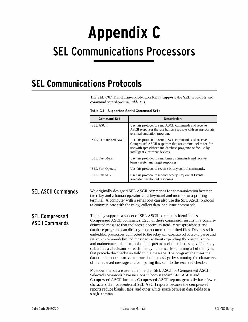
Date Code 20150130 Instruction Manual SEL-787 Relay
Appendix CSEL Communications Processors
Instruction Manual
SEL Communications ProtocolsThe SEL-787 Transformer Protection Relay supports the SEL protocols and command sets shown in Table C.1.
SEL ASCII Commands We originally designed SEL ASCII commands for communication between the relay and a human operator via a keyboard and monitor or a printing terminal. A computer with a serial port can also use the SEL ASCII protocol to communicate with the relay, collect data, and issue commands.
SEL Compressed ASCII Commands
The relay supports a subset of SEL ASCII commands identified as Compressed ASCII commands. Each of these commands results in a comma-delimited message that includes a checksum field. Most spreadsheet and database programs can directly import comma-delimited files. Devices with embedded processors connected to the relay can execute software to parse and interpret comma-delimited messages without expending the customization and maintenance labor needed to interpret nondelimited messages. The relay calculates a checksum for each line by numerically summing all of the bytes that precede the checksum field in the message. The program that uses the data can detect transmission errors in the message by summing the characters of the received message and comparing this sum to the received checksum.
Most commands are available in either SEL ASCII or Compressed ASCII. Selected commands have versions in both standard SEL ASCII and Compressed ASCII formats. Compressed ASCII reports generally have fewer characters than conventional SEL ASCII reports because the compressed reports reduce blanks, tabs, and other white space between data fields to a single comma.
Table C.1 Supported Serial Command Sets
Command Set Description
SEL ASCII Use this protocol to send ASCII commands and receive ASCII responses that are human readable with an appropriate terminal emulation program.
SEL Compressed ASCII Use this protocol to send ASCII commands and receive Compressed ASCII responses that are comma-delimited for use with spreadsheet and database programs or for use by intelligent electronic devices.
SEL Fast Meter Use this protocol to send binary commands and receive binary meter and target responses.
SEL Fast Operate Use this protocol to receive binary control commands.
SEL Fast SER Use this protocol to receive binary Sequential Events Recorder unsolicited responses.
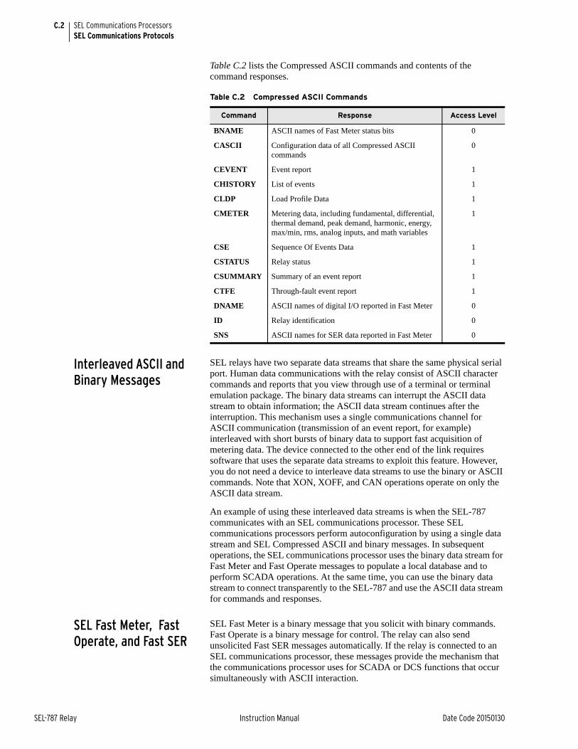
C.2
SEL-787 Relay Instruction Manual Date Code 20150130
SEL Communications ProcessorsSEL Communications Protocols
Table C.2 lists the Compressed ASCII commands and contents of the command responses.
Interleaved ASCII and Binary Messages
SEL relays have two separate data streams that share the same physical serial port. Human data communications with the relay consist of ASCII character commands and reports that you view through use of a terminal or terminal emulation package. The binary data streams can interrupt the ASCII data stream to obtain information; the ASCII data stream continues after the interruption. This mechanism uses a single communications channel for ASCII communication (transmission of an event report, for example) interleaved with short bursts of binary data to support fast acquisition of metering data. The device connected to the other end of the link requires software that uses the separate data streams to exploit this feature. However, you do not need a device to interleave data streams to use the binary or ASCII commands. Note that XON, XOFF, and CAN operations operate on only the ASCII data stream.
An example of using these interleaved data streams is when the SEL-787 communicates with an SEL communications processor. These SEL communications processors perform autoconfiguration by using a single data stream and SEL Compressed ASCII and binary messages. In subsequent operations, the SEL communications processor uses the binary data stream for Fast Meter and Fast Operate messages to populate a local database and to perform SCADA operations. At the same time, you can use the binary data stream to connect transparently to the SEL-787 and use the ASCII data stream for commands and responses.
SEL Fast Meter, Fast Operate, and Fast SER
SEL Fast Meter is a binary message that you solicit with binary commands. Fast Operate is a binary message for control. The relay can also send unsolicited Fast SER messages automatically. If the relay is connected to an SEL communications processor, these messages provide the mechanism that the communications processor uses for SCADA or DCS functions that occur simultaneously with ASCII interaction.
Table C.2 Compressed ASCII Commands
Command Response Access Level
BNAME ASCII names of Fast Meter status bits 0
CASCII Configuration data of all Compressed ASCII commands
0
CEVENT Event report 1
CHISTORY List of events 1
CLDP Load Profile Data 1
CMETER Metering data, including fundamental, differential, thermal demand, peak demand, harmonic, energy, max/min, rms, analog inputs, and math variables
1
CSE Sequence Of Events Data 1
CSTATUS Relay status 1
CSUMMARY Summary of an event report 1
CTFE Through-fault event report 1
DNAME ASCII names of digital I/O reported in Fast Meter 0
ID Relay identification 0
SNS ASCII names for SER data reported in Fast Meter 0
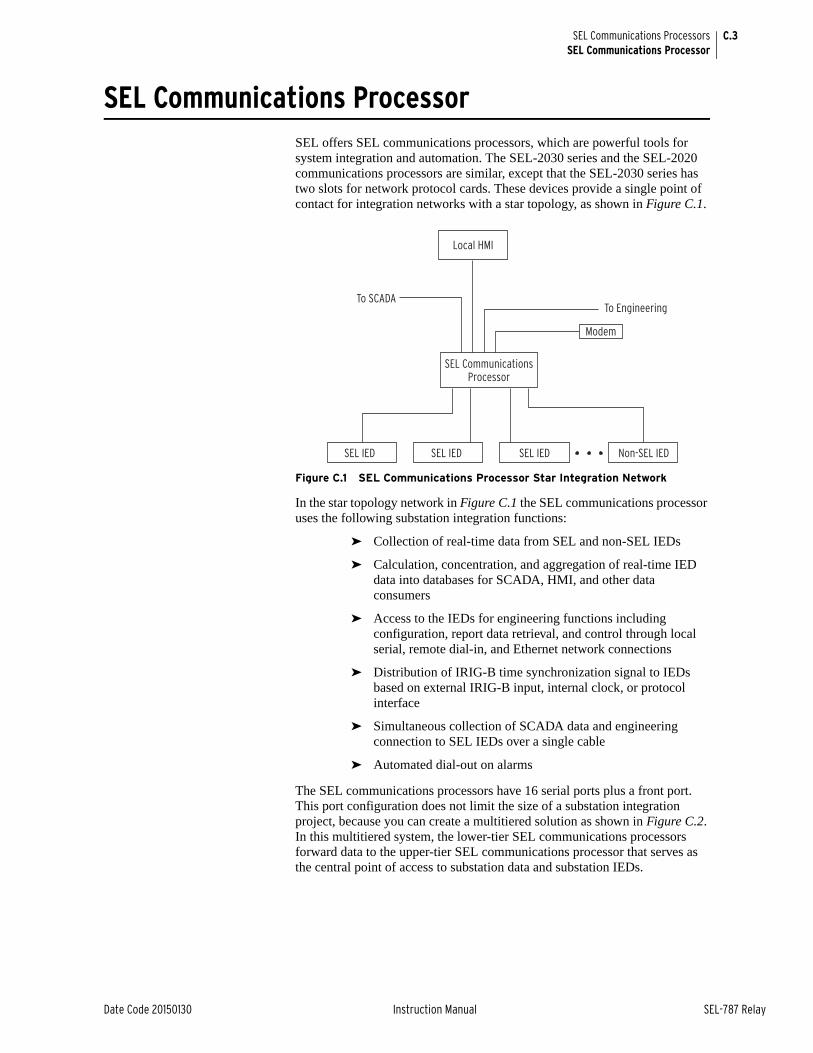
C.3
Date Code 20150130 Instruction Manual SEL-787 Relay
SEL Communications ProcessorsSEL Communications Processor
SEL Communications ProcessorSEL offers SEL communications processors, which are powerful tools for system integration and automation. The SEL-2030 series and the SEL-2020 communications processors are similar, except that the SEL-2030 series has two slots for network protocol cards. These devices provide a single point of contact for integration networks with a star topology, as shown in Figure C.1.
Figure C.1 SEL Communications Processor Star Integration Network
In the star topology network in Figure C.1 the SEL communications processor uses the following substation integration functions:
➤ Collection of real-time data from SEL and non-SEL IEDs
➤ Calculation, concentration, and aggregation of real-time IED data into databases for SCADA, HMI, and other data consumers
➤ Access to the IEDs for engineering functions including configuration, report data retrieval, and control through local serial, remote dial-in, and Ethernet network connections
➤ Distribution of IRIG-B time synchronization signal to IEDs based on external IRIG-B input, internal clock, or protocol interface
➤ Simultaneous collection of SCADA data and engineering connection to SEL IEDs over a single cable
➤ Automated dial-out on alarms
The SEL communications processors have 16 serial ports plus a front port. This port configuration does not limit the size of a substation integration project, because you can create a multitiered solution as shown in Figure C.2. In this multitiered system, the lower-tier SEL communications processors forward data to the upper-tier SEL communications processor that serves as the central point of access to substation data and substation IEDs.
SEL CommunicationsProcessor
To Engineering
Modem
To SCADA
Local HMI
SEL IED SEL IED SEL IED Non-SEL IED
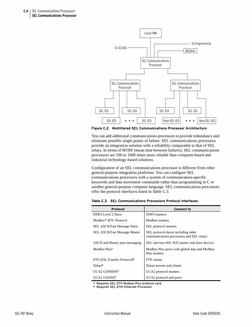
C.4
SEL-787 Relay Instruction Manual Date Code 20150130
SEL Communications ProcessorsSEL Communications Processor
Figure C.2 Multitiered SEL Communications Processor Architecture
You can add additional communications processors to provide redundancy and eliminate possible single points of failure. SEL communications processors provide an integration solution with a reliability comparable to that of SEL relays. In terms of MTBF (mean time between failures), SEL communications processors are 100 to 1000 times more reliable than computer-based and industrial technology-based solutions.
Configuration of an SEL communications processor is different from other general-purpose integration platforms. You can configure SEL communications processors with a system of communication-specific keywords and data movement commands rather than programming in C or another general-purpose computer language. SEL communications processors offer the protocol interfaces listed in Table C.3.
Table C.3 SEL Communications Processors Protocol Interfaces
Protocol Connect to
DNP3 Level 2 Slave DNP3 masters
Modbus® RTU Protocol Modbus masters
SEL ASCII/Fast Message Slave SEL protocol masters
SEL ASCII/Fast Message Master SEL protocol slaves including other communications processors and SEL relays
ASCII and Binary auto messaging SEL and non-SEL IED master and slave devices
Modbus Plusa
a Requires SEL-2711 Modbus Plus protocol card.
Modbus Plus peers with global data and Modbus Plus masters
FTP (File Transfer Protocol)b
b Requires SEL-2701 Ethernet Processor.
FTP clients
Telnetb Telnet servers and clients
UCA2 GOMSFEb UCA2 protocol masters
UCA2 GOOSEb UCA2 protocol and peers
SEL CommunicationsProcessor
To Engineering
ModemTo SCADA
Local HMI
SEL IED
SEL IED
SEL IED
Non-SEL IED
SEL IED
SEL IED
SEL IED
Non-SEL IED
SEL CommunicationsProcessor
SEL CommunicationsProcessor
C.5
Date Code 20150130 Instruction Manual SEL-787 Relay
SEL Communications ProcessorsSEL Communications Processor and Relay Architecture
SEL Communications Processor and Relay Architecture
You can apply SEL communications processors and SEL relays in a limitless variety of applications to integrate, automate, and improve station operation. Most system integration architectures using SEL communications processors involve either developing a star network or enhancing a multidrop network.
Developing Star Networks
The simplest architecture using both the SEL-787 and an SEL communications processor is shown in Figure C.1. In this architecture, the SEL communications processor collects data from the SEL-787 and other station IEDs. The SEL communications processor acts as a single point of access for local and remote data consumers (local HMI, SCADA, engineers). The communications processor also provides a single point of access for engineering operations including configuration and the collection of report-based information.
By configuring a data set optimized to each data consumer, you can significantly increase the utilization efficiency on each link. A system that uses an SEL communications processor to provide a protocol interface to an RTU will have a shorter lag time (data latency); communication overhead is much less for a single data exchange conversation to collect all substation data (from a communications processor) than for many conversations required to collect data directly from each individual IED. You can further reduce data latency by connecting any SEL communications processor directly to the SCADA master thereby eliminating redundant communication processing in the RTU.
The SEL communications processor is responsible for the protocol interface, so you can install, test, and even upgrade the system in the future without disturbing protective relays and other station IEDs. This insulation of the protective devices from the communications interface assists greatly in situations where different departments are responsible for SCADA operation, communication, and protection.
SEL communications processors equipped with an SEL-2701 Ethernet Processor can provide a UCA2 interface to SEL-787 relays and other serial IEDs. The SEL-787 data appear in models in a virtual device domain. The combination of the SEL-2701 with an SEL communications processor offers a significant cost savings because you can use existing IEDs or purchase less expensive IEDs. For full details on applying the SEL-2701 with an SEL communications processor, see the SEL-2701 Ethernet Processor Instruction Manual.
The engineering connection can use either an Ethernet network connection through the SEL-2701 or a serial port connection. This versatility will accommodate the channel that is available between the station and the engineering center. SEL software can use either a serial port connection or an Ethernet network connection from an engineering workstation to the relays in the field.
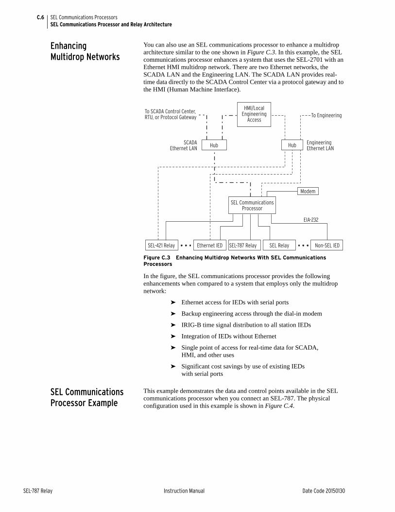
C.6
SEL-787 Relay Instruction Manual Date Code 20150130
SEL Communications ProcessorsSEL Communications Processor and Relay Architecture
Enhancing Multidrop Networks
You can also use an SEL communications processor to enhance a multidrop architecture similar to the one shown in Figure C.3. In this example, the SEL communications processor enhances a system that uses the SEL-2701 with an Ethernet HMI multidrop network. There are two Ethernet networks, the SCADA LAN and the Engineering LAN. The SCADA LAN provides real-time data directly to the SCADA Control Center via a protocol gateway and to the HMI (Human Machine Interface).
Figure C.3 Enhancing Multidrop Networks With SEL Communications Processors
In the figure, the SEL communications processor provides the following enhancements when compared to a system that employs only the multidrop network:
➤ Ethernet access for IEDs with serial ports
➤ Backup engineering access through the dial-in modem
➤ IRIG-B time signal distribution to all station IEDs
➤ Integration of IEDs without Ethernet
➤ Single point of access for real-time data for SCADA, HMI, and other uses
➤ Significant cost savings by use of existing IEDs with serial ports
SEL Communications Processor Example
This example demonstrates the data and control points available in the SEL communications processor when you connect an SEL-787. The physical configuration used in this example is shown in Figure C.4.
SEL CommunicationsProcessor
Modem
To SCADA Control Center,RTU, or Protocol Gateway To Engineering
HMI/Local Engineering
Access
SEL-421 Relay
Hub Hub
Ethernet IED
SCADA Ethernet LAN
EIA-232
EngineeringEthernet LAN
SEL-787 Relay SEL Relay Non-SEL IED
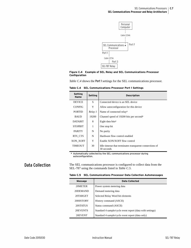
C.7
Date Code 20150130 Instruction Manual SEL-787 Relay
SEL Communications ProcessorsSEL Communications Processor and Relay Architecture
Figure C.4 Example of SEL Relay and SEL Communications Processor Configuration
Table C.4 shows the Port 1 settings for the SEL communications processor.
Data Collection The SEL communications processor is configured to collect data from the SEL-787 using the commands listed in Table C.5.
Table C.4 SEL Communications Processor Port 1 Settings
Setting Name
Setting Description
DEVICE S Connected device is an SEL device
CONFIG Y Allow autoconfiguration for this device
PORTID Relay 1 Name of connected relaya
a Automatically collected by the SEL communications processor during autoconfiguration.
BAUD 19200 Channel speed of 19200 bits per seconda
DATABIT 8 Eight data bitsa
STOPBIT 1 One stop bit
PARITY N No parity
RTS_CTS N Hardware flow control enabled
XON_XOFF Y Enable XON/XOFF flow control
TIMEOUT 30 Idle timeout that terminates transparent connections of 30 seconds
SEL CommunicationsProcessor
SEL-787 Relay
Personal Computer
Port F
Port 1
Port 3Cable C273A
Cable C234A
Table C.5 SEL Communications Processor Data Collection Automessages
Message Data Collected
20METER Power system metering data
20DEMAND Demand metering data
20TARGET Selected Relay Word bit elements
20HISTORY History command (ASCII)
20STATUS Status command (ASCII)
20EVENTS Standard 4 sample/cycle event report (data with settings)
20EVENT Standard 4 sample/cycle event report (data only)
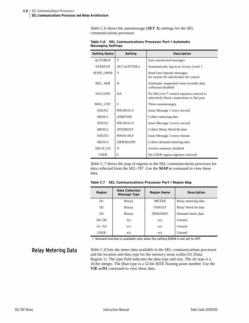
C.8
SEL-787 Relay Instruction Manual Date Code 20150130
SEL Communications ProcessorsSEL Communications Processor and Relay Architecture
Table C.6 shows the automessage (SET A) settings for the SEL communications processor.
Table C.7 shows the map of regions in the SEL communications processor for data collected from the SEL-787. Use the MAP n command to view these data.
Relay Metering Data Table C.8 lists the meter data available in the SEL communications processor and the location and data type for the memory areas within D1 (Data Region 1). The type field indicates the data type and size. The int type is a 16-bit integer. The float type is a 32-bit IEEE floating point number. Use the VIE n:D1 command to view these data.
Table C.6 SEL Communications Processor Port 1 Automatic Messaging Settings
Setting Name Setting Description
AUTOBUF Y Save unsolicited messages
STARTUP ACC\nOTTER\n Automatically log-in at Access Level 1
SEND_OPER Y Send Fast Operate messages for remote bit and breaker bit control
REC_SER N Automatic sequential event recorder data collection disabled
NOCONN NA No SELOGIC® control equation entered to selectively block connections to this port
MSG_CNT 3 Three automessages
ISSUE1 P00:00:01.0 Issue Message 1 every second
MESG1 20METER Collect metering data
ISSUE2 P00:00:01.0 Issue Message 2 every second
MESG2 20TARGET Collect Relay Word bit data
ISSUE3 P00:01:00.0 Issue Message 3 every minute
MESG3 20DEMAND Collect demand metering data
ARCH_EN N Archive memory disabled
USER 0 No USER region registers reserved
Table C.7 SEL Communications Processor Port 1 Region Map
RegionData CollectionMessage Type
Region Name Description
D1 Binary METER Relay metering data
D2 Binary TARGET Relay Word bit data
D3 Binary DEMANDa
a Demand function is available only when the setting EDEM is not set to OFF.
Demand meter data
D4–D8 n/a n/a Unused
A1–A3 n/a n/a Unused
USER n/a n/a Unused
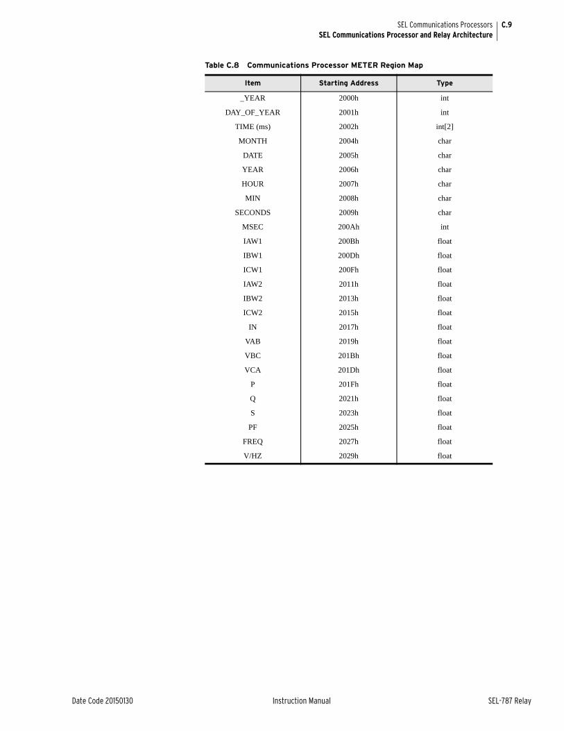
C.9
Date Code 20150130 Instruction Manual SEL-787 Relay
SEL Communications ProcessorsSEL Communications Processor and Relay Architecture
Table C.8 Communications Processor METER Region Map
Item Starting Address Type
_YEAR 2000h int
DAY_OF_YEAR 2001h int
TIME (ms) 2002h int[2]
MONTH 2004h char
DATE 2005h char
YEAR 2006h char
HOUR 2007h char
MIN 2008h char
SECONDS 2009h char
MSEC 200Ah int
IAW1 200Bh float
IBW1 200Dh float
ICW1 200Fh float
IAW2 2011h float
IBW2 2013h float
ICW2 2015h float
IN 2017h float
VAB 2019h float
VBC 201Bh float
VCA 201Dh float
P 201Fh float
Q 2021h float
S 2023h float
PF 2025h float
FREQ 2027h float
V/HZ 2029h float
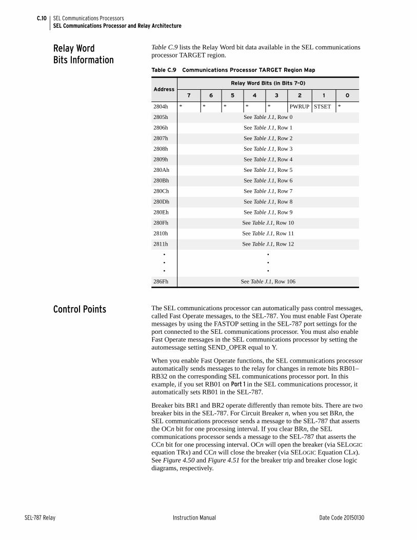
C.10
SEL-787 Relay Instruction Manual Date Code 20150130
SEL Communications ProcessorsSEL Communications Processor and Relay Architecture
Relay Word Bits Information
Table C.9 lists the Relay Word bit data available in the SEL communications processor TARGET region.
Control Points The SEL communications processor can automatically pass control messages, called Fast Operate messages, to the SEL-787. You must enable Fast Operate messages by using the FASTOP setting in the SEL-787 port settings for the port connected to the SEL communications processor. You must also enable Fast Operate messages in the SEL communications processor by setting the automessage setting SEND_OPER equal to Y.
When you enable Fast Operate functions, the SEL communications processor automatically sends messages to the relay for changes in remote bits RB01–RB32 on the corresponding SEL communications processor port. In this example, if you set RB01 on Port 1 in the SEL communications processor, it automatically sets RB01 in the SEL-787.
Breaker bits BR1 and BR2 operate differently than remote bits. There are two breaker bits in the SEL-787. For Circuit Breaker n, when you set BRn, the SEL communications processor sends a message to the SEL-787 that asserts the OCn bit for one processing interval. If you clear BRn, the SEL communications processor sends a message to the SEL-787 that asserts the CCn bit for one processing interval. OCn will open the breaker (via SELOGIC equation TRx) and CCn will close the breaker (via SELOGIC Equation CLx). See Figure 4.50 and Figure 4.51 for the breaker trip and breaker close logic diagrams, respectively.
Table C.9 Communications Processor TARGET Region Map
AddressRelay Word Bits (in Bits 7–0)
7 6 5 4 3 2 1 0
2804h * * * * * PWRUP STSET *
2805h See Table J.1, Row 0
2806h See Table J.1, Row 1
2807h See Table J.1, Row 2
2808h See Table J.1, Row 3
2809h See Table J.1, Row 4
280Ah See Table J.1, Row 5
280Bh See Table J.1, Row 6
280Ch See Table J.1, Row 7
280Dh See Table J.1, Row 8
280Eh See Table J.1, Row 9
280Fh See Table J.1, Row 10
2810h See Table J.1, Row 11
2811h See Table J.1, Row 12
•
•
•
•
•
•
286Fh See Table J.1, Row 106
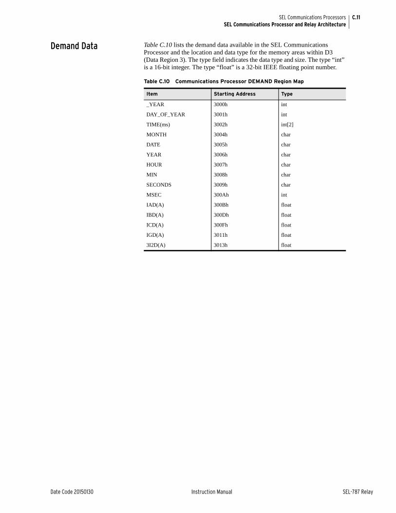
C.11
Date Code 20150130 Instruction Manual SEL-787 Relay
SEL Communications ProcessorsSEL Communications Processor and Relay Architecture
Demand Data Table C.10 lists the demand data available in the SEL Communications Processor and the location and data type for the memory areas within D3 (Data Region 3). The type field indicates the data type and size. The type “int” is a 16-bit integer. The type “float” is a 32-bit IEEE floating point number.
Table C.10 Communications Processor DEMAND Region Map
Item Starting Address Type
_YEAR 3000h int
DAY_OF_YEAR 3001h int
TIME(ms) 3002h int[2]
MONTH 3004h char
DATE 3005h char
YEAR 3006h char
HOUR 3007h char
MIN 3008h char
SECONDS 3009h char
MSEC 300Ah int
IAD(A) 300Bh float
IBD(A) 300Dh float
ICD(A) 300Fh float
IGD(A) 3011h float
3I2D(A) 3013h float

This page intentionally left blank
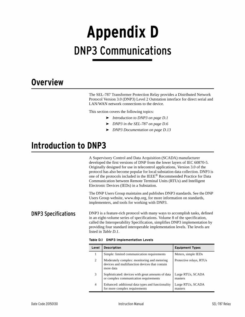
Date Code 20150130 Instruction Manual SEL-787 Relay
Appendix DDNP3 Communications
Instruction Manual
OverviewThe SEL-787 Transformer Protection Relay provides a Distributed Network Protocol Version 3.0 (DNP3) Level 2 Outstation interface for direct serial and LAN/WAN network connections to the device.
This section covers the following topics:
➤ Introduction to DNP3 on page D.1
➤ DNP3 in the SEL-787 on page D.6
➤ DNP3 Documentation on page D.13
Introduction to DNP3A Supervisory Control and Data Acquisition (SCADA) manufacturer developed the first versions of DNP from the lower layers of IEC 60870-5. Originally designed for use in telecontrol applications, Version 3.0 of the protocol has also become popular for local substation data collection. DNP3 is one of the protocols included in the IEEE® Recommended Practice for Data Communication between Remote Terminal Units (RTUs) and Intelligent Electronic Devices (IEDs) in a Substation.
The DNP Users Group maintains and publishes DNP3 standards. See the DNP Users Group website, www.dnp.org, for more information on standards, implementers, and tools for working with DNP3.
DNP3 Specifications DNP3 is a feature-rich protocol with many ways to accomplish tasks, defined in an eight-volume series of specifications. Volume 8 of the specification, called the Interoperability Specification, simplifies DNP3 implementation by providing four standard interoperable implementation levels. The levels are listed in Table D.1.
Table D.1 DNP3 Implementation Levels
Level Description Equipment Types
1 Simple: limited communication requirements Meters, simple IEDs
2 Moderately complex: monitoring and metering devices and multifunction devices that contain more data
Protective relays, RTUs
3 Sophisticated: devices with great amounts of data or complex communication requirements
Large RTUs, SCADA masters
4 Enhanced: additional data types and functionality for more complex requirements
Large RTUs, SCADA masters
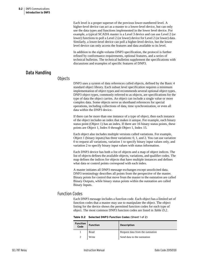
D.2
SEL-787 Relay Instruction Manual Date Code 20150130
DNP3 CommunicationsIntroduction to DNP3
Each level is a proper superset of the previous lower-numbered level. A higher-level device can act as a master to a lower-level device, but can only use the data types and functions implemented in the lower level device. For example, a typical SCADA master is a Level 3 device and can use Level 2 (or lower) functions to poll a Level 2 (or lower) device for Level 2 (or lower) data. Similarly, a lower-level device can poll a higher-level device, but the lower level device can only access the features and data available to its level.
In addition to the eight-volume DNP3 specification, the protocol is further refined by conformance requirements, optional features, and a series of technical bulletins. The technical bulletins supplement the specifications with discussions and examples of specific features of DNP3.
Data HandlingObjects
DNP3 uses a system of data references called objects, defined by the Basic 4 standard object library. Each subset level specification requires a minimum implementation of object types and recommends several optional object types. DNP3 object types, commonly referred to as objects, are specifications for the type of data the object carries. An object can include a single value or more complex data. Some objects serve as shorthand references for special operations, including collections of data, time synchronization, or even all data within the DNP3 device.
If there can be more than one instance of a type of object, then each instance of the object includes an index that makes it unique. For example, each binary status point (Object 1) has an index. If there are 16 binary status points, these points are Object 1, Index 0 through Object 1, Index 15.
Each object also includes multiple versions called variations. For example, Object 1 (binary inputs) has three variations: 0, 1, and 2. You can use variation 0 to request all variations, variation 1 to specify binary input values only, and variation 2 to specify binary input values with status information.
Each DNP3 device has both a list of objects and a map of object indices. The list of objects defines the available objects, variations, and qualifier codes. The map defines the indices for objects that have multiple instances and defines what data or control points correspond with each index.
A master initiates all DNP3 message exchanges except unsolicited data. DNP3 terminology describes all points from the perspective of the master. Binary points for control that move from the master to the outstation are called Binary Outputs, while binary status points within the outstation are called Binary Inputs.
Function CodesEach DNP3 message includes a function code. Each object has a limited set of function codes that a master may use to manipulate the object. The object listing for the device shows the permitted function codes for each type of object. The most common DNP3 function codes are listed in Table D.2.
Table D.2 Selected DNP3 Function Codes (Sheet 1 of 2)
Function Code
Function Description
1 Read Request data from the outstation
2 Write Send data to the outstation
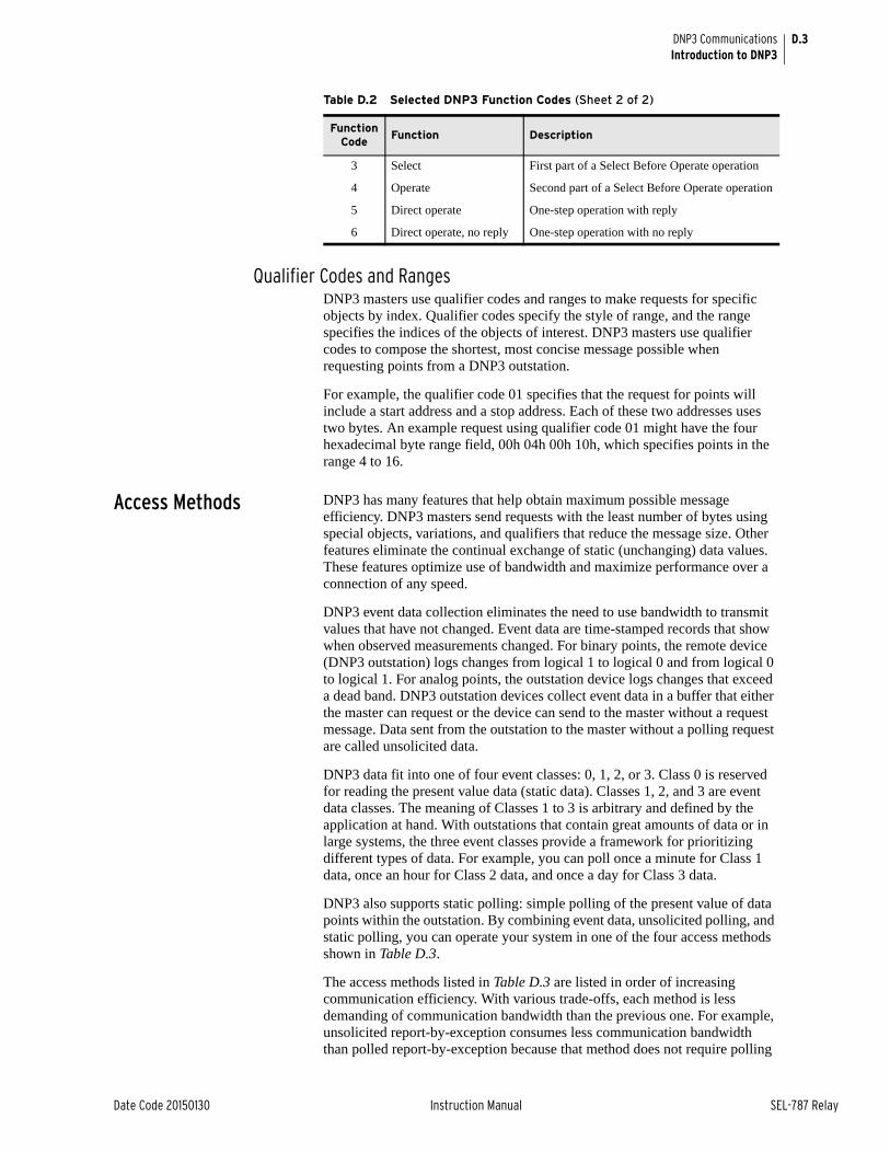
D.3
Date Code 20150130 Instruction Manual SEL-787 Relay
DNP3 CommunicationsIntroduction to DNP3
Qualifier Codes and RangesDNP3 masters use qualifier codes and ranges to make requests for specific objects by index. Qualifier codes specify the style of range, and the range specifies the indices of the objects of interest. DNP3 masters use qualifier codes to compose the shortest, most concise message possible when requesting points from a DNP3 outstation.
For example, the qualifier code 01 specifies that the request for points will include a start address and a stop address. Each of these two addresses uses two bytes. An example request using qualifier code 01 might have the four hexadecimal byte range field, 00h 04h 00h 10h, which specifies points in the range 4 to 16.
Access Methods DNP3 has many features that help obtain maximum possible message efficiency. DNP3 masters send requests with the least number of bytes using special objects, variations, and qualifiers that reduce the message size. Other features eliminate the continual exchange of static (unchanging) data values. These features optimize use of bandwidth and maximize performance over a connection of any speed.
DNP3 event data collection eliminates the need to use bandwidth to transmit values that have not changed. Event data are time-stamped records that show when observed measurements changed. For binary points, the remote device (DNP3 outstation) logs changes from logical 1 to logical 0 and from logical 0 to logical 1. For analog points, the outstation device logs changes that exceed a dead band. DNP3 outstation devices collect event data in a buffer that either the master can request or the device can send to the master without a request message. Data sent from the outstation to the master without a polling request are called unsolicited data.
DNP3 data fit into one of four event classes: 0, 1, 2, or 3. Class 0 is reserved for reading the present value data (static data). Classes 1, 2, and 3 are event data classes. The meaning of Classes 1 to 3 is arbitrary and defined by the application at hand. With outstations that contain great amounts of data or in large systems, the three event classes provide a framework for prioritizing different types of data. For example, you can poll once a minute for Class 1 data, once an hour for Class 2 data, and once a day for Class 3 data.
DNP3 also supports static polling: simple polling of the present value of data points within the outstation. By combining event data, unsolicited polling, and static polling, you can operate your system in one of the four access methods shown in Table D.3.
The access methods listed in Table D.3 are listed in order of increasing communication efficiency. With various trade-offs, each method is less demanding of communication bandwidth than the previous one. For example, unsolicited report-by-exception consumes less communication bandwidth than polled report-by-exception because that method does not require polling
3 Select First part of a Select Before Operate operation
4 Operate Second part of a Select Before Operate operation
5 Direct operate One-step operation with reply
6 Direct operate, no reply One-step operation with no reply
Table D.2 Selected DNP3 Function Codes (Sheet 2 of 2)
Function Code
Function Description
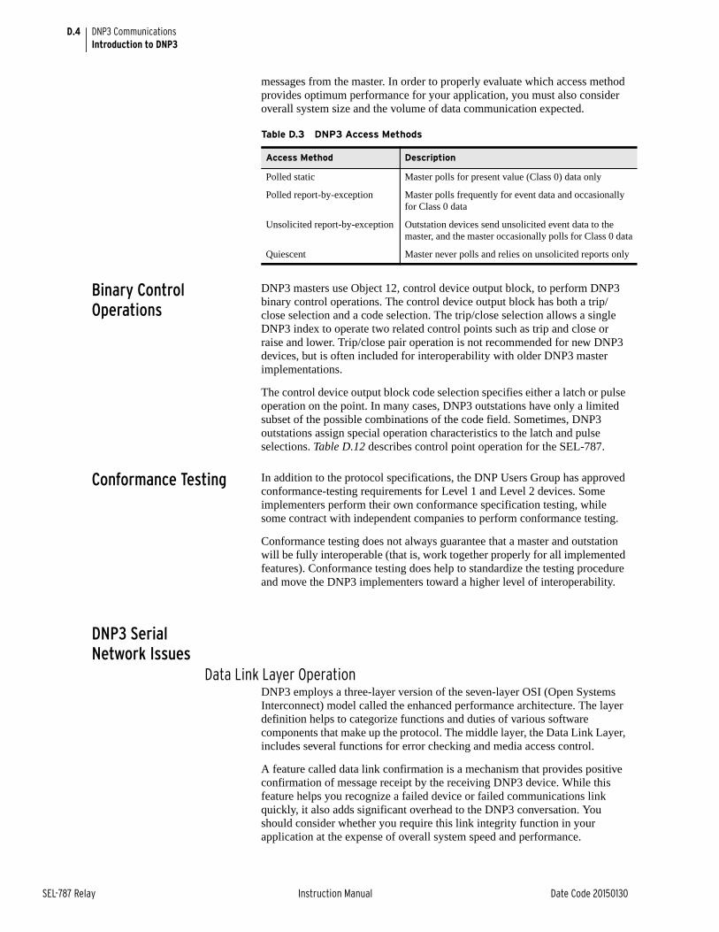
D.4
SEL-787 Relay Instruction Manual Date Code 20150130
DNP3 CommunicationsIntroduction to DNP3
messages from the master. In order to properly evaluate which access method provides optimum performance for your application, you must also consider overall system size and the volume of data communication expected.
Binary Control Operations
DNP3 masters use Object 12, control device output block, to perform DNP3 binary control operations. The control device output block has both a trip/close selection and a code selection. The trip/close selection allows a single DNP3 index to operate two related control points such as trip and close or raise and lower. Trip/close pair operation is not recommended for new DNP3 devices, but is often included for interoperability with older DNP3 master implementations.
The control device output block code selection specifies either a latch or pulse operation on the point. In many cases, DNP3 outstations have only a limited subset of the possible combinations of the code field. Sometimes, DNP3 outstations assign special operation characteristics to the latch and pulse selections. Table D.12 describes control point operation for the SEL-787.
Conformance Testing In addition to the protocol specifications, the DNP Users Group has approved conformance-testing requirements for Level 1 and Level 2 devices. Some implementers perform their own conformance specification testing, while some contract with independent companies to perform conformance testing.
Conformance testing does not always guarantee that a master and outstation will be fully interoperable (that is, work together properly for all implemented features). Conformance testing does help to standardize the testing procedure and move the DNP3 implementers toward a higher level of interoperability.
DNP3 Serial Network Issues
Data Link Layer OperationDNP3 employs a three-layer version of the seven-layer OSI (Open Systems Interconnect) model called the enhanced performance architecture. The layer definition helps to categorize functions and duties of various software components that make up the protocol. The middle layer, the Data Link Layer, includes several functions for error checking and media access control.
A feature called data link confirmation is a mechanism that provides positive confirmation of message receipt by the receiving DNP3 device. While this feature helps you recognize a failed device or failed communications link quickly, it also adds significant overhead to the DNP3 conversation. You should consider whether you require this link integrity function in your application at the expense of overall system speed and performance.
Table D.3 DNP3 Access Methods
Access Method Description
Polled static Master polls for present value (Class 0) data only
Polled report-by-exception Master polls frequently for event data and occasionally for Class 0 data
Unsolicited report-by-exception Outstation devices send unsolicited event data to the master, and the master occasionally polls for Class 0 data
Quiescent Master never polls and relies on unsolicited reports only
D.5
Date Code 20150130 Instruction Manual SEL-787 Relay
DNP3 CommunicationsIntroduction to DNP3
The DNP3 technical bulletin (DNP Confirmation and Retry Guidelines 9804-002) on confirmation processes recommends against using data link confirmations because these processes can add to traffic in situations where communications are marginal. The increased traffic will reduce connection throughput further, possibly preventing the system from operating properly.
Network Medium ContentionWhen more than one device requires access to a single (serial) network medium, you must provide a mechanism to resolve the resulting network medium contention. For example, unsolicited reporting results in network medium contention if you do not design your serial network as a star topology of point-to point connections or use carrier detection on a multidrop network.
To avoid collisions among devices trying to send messages, DNP3 includes a collision avoidance feature. Before sending a message, a DNP3 device listens for a carrier signal to verify that no other node is transmitting data. The device transmits if there is no carrier or waits for a random time before transmitting. However, if two nodes both detect a lack of carrier at the same instant, these two nodes could begin simultaneous transmission of data and cause a data collision. If your serial network allows for spontaneous data transmission including unsolicited event data transmissions, you also must use application confirmation to provide a retry mechanism for messages lost due to data collisions.
DNP3 LAN/WAN Overview
The main process for carrying DNP3 over an Ethernet Network (LAN/WAN) involves encapsulating the DNP3 data link layer data frames within the transport layer frames of the Internet Protocol (IP) suite. This allows the IP stack to deliver the DNP3 data link layer frames to the destination in place of the original DNP3 physical layer.The DNP User Group Technical Committee has recommended the following guidelines for carrying DNP3 over a network:
NOTE: Link layer confirmations are explicitly disabled for DNP3 LAN/WAN. The IP suite provides a reliable delivery mechanism, which is backed up at the application layer by confirmations when required.
➤ DNP3 shall use the IP suite to transport messages over a LAN/WAN
➤ Ethernet is the recommended physical link, though others may be used
➤ TCP must be used for WANs
➤ TCP is strongly recommended for LANs
➤ User Datagram Protocol (UDP) may be used for highly reliable single segment LANs
➤ UDP is necessary if broadcast messages are required
➤ The DNP3 protocol stack shall be retained in full
➤ Link layer confirmations shall be disabled
The Technical Committee has registered a standard port number, 20000, for DNP3 with the Internet Assigned Numbers Authority (IANA). This port is used for either TCP or UDP.
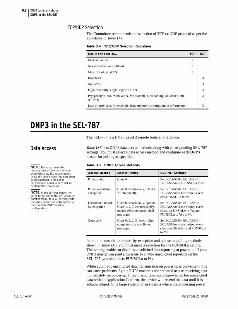
D.6
SEL-787 Relay Instruction Manual Date Code 20150130
DNP3 CommunicationsDNP3 in the SEL-787
TCP/UDP SelectionThe Committee recommends the selection of TCP or UDP protocol as per the guidelines in Table D.4.
DNP3 in the SEL-787The SEL-787 is a DNP3 Level 2 remote (outstation) device.
Data Access Table D.5 lists DNP3 data access methods along with corresponding SEL-787 settings. You must select a data access method and configure each DNP3 master for polling as specified.
In both the unsolicited report-by-exception and quiescent polling methods shown in Table D.5, you must make a selection for the PUNSOLn setting. This setting enables or disables unsolicited data reporting at power up. If your DNP3 master can send a message to enable unsolicited reporting on the SEL-787, you should set PUNSOLn to No.
While automatic unsolicited data transmission on power up is convenient, this can cause problems if your DNP3 master is not prepared to start receiving data immediately on power up. If the master does not acknowledge the unsolicited data with an Application Confirm, the device will resend the data until it is acknowledged. On a large system, or in systems where the processing power
Table D.4 TCP/UDP Selection Guidelines
Use in the case of… TCP UDP
Most situations X
Non-broadcast or multicast X
Mesh Topology WAN X
Broadcast X
Multicast X
High-reliability single-segment LAN X
Pay-per-byte, non-mesh WAN, for example, Cellular Digital Packet Data (CDPD)
X
Low priority data, for example, data monitor or configuration information X
Table D.5 DNP3 Access Methods
Access Method Master Polling SEL-787 Settings
Polled static Class 0 Set ECLASSBn, ECLASSCn, ECLASSAn to 0; UNSOLn to No
Polled report-by-exception
Class 0 occasionally, Class 1, 2, 3 frequently
Set ECLASSBn, ECLASSCn, ECLASSAn to the desired event class; UNSOLn to No
Unsolicited report-by-exception
Class 0 occasionally, optional Class 1, 2, 3 less frequently; mainly relies on unsolicited messages
Set ECLASSBn, ECLASSCn, ECLASSAn to the desired event class; set UNSOLn to Yes and PUNSOLn to Yes or No
Quiescent Class 0, 1, 2, 3 never; relies completely on unsolicited messages
Set ECLASSBn, ECLASSCn, ECLASSAn to the desired event class; set UNSOLn and PUNSOLn to Yes.
NOTE: Because unsolicited messaging is problematic in most circumstances, SEL recommends using the polled report-by-exception access method to maximize performance and minimize risk of configuration problems.
NOTE: In the settings below, the suffix n represents the DNP3 session number from 1 to 3. All settings with the same numerical suffix comprise the complete DNP3 session configuration.
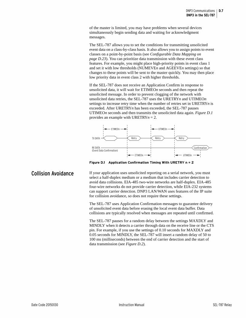
D.7
Date Code 20150130 Instruction Manual SEL-787 Relay
DNP3 CommunicationsDNP3 in the SEL-787
of the master is limited, you may have problems when several devices simultaneously begin sending data and waiting for acknowledgment messages.
The SEL-787 allows you to set the conditions for transmitting unsolicited event data on a class-by-class basis. It also allows you to assign points to event classes on a point-by-point basis (see Configurable Data Mapping on page D.23). You can prioritize data transmission with these event class features. For example, you might place high-priority points in event class 1 and set it with low thresholds (NUMEVEn and AGEEVEn settings) so that changes to these points will be sent to the master quickly. You may then place low priority data in event class 2 with higher thresholds.
If the SEL-787 does not receive an Application Confirm in response to unsolicited data, it will wait for ETIMEOn seconds and then repeat the unsolicited message. In order to prevent clogging of the network with unsolicited data retries, the SEL-787 uses the URETRYn and UTIMEOn settings to increase retry time when the number of retries set in URETRYn is exceeded. After URETRYn has been exceeded, the SEL-787 pauses UTIMEOn seconds and then transmits the unsolicited data again. Figure D.1 provides an example with URETRYn = 2.
Figure D.1 Application Confirmation Timing With URETRY n = 2
Collision Avoidance If your application uses unsolicited reporting on a serial network, you must select a half-duplex medium or a medium that includes carrier detection to avoid data collisions. EIA-485 two-wire networks are half-duplex. EIA-485 four-wire networks do not provide carrier detection, while EIA-232 systems can support carrier detection. DNP3 LAN/WAN uses features of the IP suite for collision avoidance, so does not require these settings.
The SEL-787 uses Application Confirmation messages to guarantee delivery of unsolicited event data before erasing the local event data buffer. Data collisions are typically resolved when messages are repeated until confirmed.
The SEL-787 pauses for a random delay between the settings MAXDLY and MINDLY when it detects a carrier through data on the receive line or the CTS pin. For example, if you use the settings of 0.10 seconds for MAXDLY and 0.05 seconds for MINDLY, the SEL-787 will insert a random delay of 50 to 100 ms (milliseconds) between the end of carrier detection and the start of data transmission (see Figure D.2).
RX DATA(Event Data Confirmation)
TX DATA
ETIMEOn
Retry RetryRetry
Confirmation
UTIMEOn
UTIMEOnETIMEOn
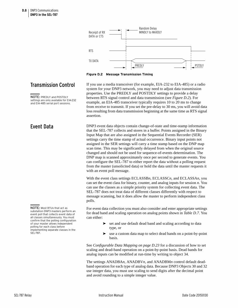
D.8
SEL-787 Relay Instruction Manual Date Code 20150130
DNP3 CommunicationsDNP3 in the SEL-787
Figure D.2 Message Transmission Timing
Transmission Control If you use a media transceiver (for example, EIA-232 to EIA-485) or a radio system for your DNP3 network, you may need to adjust data transmission properties. Use the PREDLY and POSTDLY settings to provide a delay between RTS signal control and data transmission (see Figure D.2). For example, an EIA-485 transceiver typically requires 10 to 20 ms to change from receive to transmit. If you set the pre-delay to 30 ms, you will avoid data loss resulting from data transmission beginning at the same time as RTS signal assertion.
Event Data DNP3 event data objects contain change-of-state and time-stamp information that the SEL-787 collects and stores in a buffer. Points assigned in the Binary Input Map that are also assigned in the Sequential Events Recorder (SER) settings carry the time stamp of actual occurrence. Binary input points not assigned in the SER settings will carry a time stamp based on the DNP map scan time. This may be significantly delayed from when the original source changed and should not be used for sequence-of-events determination. The DNP map is scanned approximately once per second to generate events. You can configure the SEL-787 to either report the data without a polling request from the master (unsolicited data) or hold the data until the master requests it with an event poll message.
With the event class settings ECLASSBn, ECLASSCn, and ECLASSAn, you can set the event class for binary, counter, and analog inputs for session n. You can use the classes as a simple priority system for collecting event data. The SEL-787 does not treat data of different classes differently with respect to message scanning, but it does allow the master to perform independent class polls.
NOTE: Most RTUs that act as substation DNP3 masters perform an event poll that collects event data of all classes simultaneously. You must confirm that the polling configuration of your master allows independent polling for each class before implementing separate classes in the SEL-787.
For event data collection you must also consider and enter appropriate settings for dead band and scaling operation on analog points shown in Table D.7. You can either:
➤ set and use default dead band and scaling according to data type, or
➤ use a custom data map to select dead bands on a point-by-point basis.
See Configurable Data Mapping on page D.23 for a discussion of how to set scaling and dead-band operation on a point-by-point basis. Dead bands for analog inputs can be modified at run-time by writing to object 34.
The settings ANADBAn, ANADBVn, and ANADBMn control default dead-band operation for each type of analog data. Because DNP3 Objects 30 and 32 use integer data, you must use scaling to send digits after the decimal point and avoid rounding to a simple integer value.
Receipt of RX DATA or CTS
Random DelayMINDLY to MAXDLY
RTS
TX DATAPREDLY PSTDLY
NOTE: PREDLY and POSTDLY settings are only available for EIA-232 and EIA-485 serial port sessions.
D.9
Date Code 20150130 Instruction Manual SEL-787 Relay
DNP3 CommunicationsDNP3 in the SEL-787
With no scaling, the value of 12.632 would be sent as 12. With a scaling setting of 1, the value transmitted is 126. With a scaling setting of 3, the value transmitted is 12632. You must make certain that the maximum value does not exceed 32767 if you are polling the default 16-bit variations for Objects 30 and 32, but you can send some decimal values using this technique. You must also configure the master to perform the appropriate division on the incoming value to display it properly.
You can set the default analog value scaling with the DECPLAn, DECPLVn, and DECPLMn settings. Application of event reporting dead bands occurs after scaling. For example, if you set DECPLAn to 2 and ANADBAn to 10, a measured current of 10.14 amps would be scaled to the value 1014 and would have to increase to more than 1024 or decrease to less than 1004 (a change in magnitude of ± 0.1 amps) for the device to report a new event value.
Phase angles have a default scale factor of 10, and the ANADBM dead-band setting applies to them. For the angles to generate events, the corresponding magnitude also has to exceed its dead-band setting (ANADBA).
The SEL-787 uses the NUMEVEn and AGEEVEn settings to decide when to send unsolicited data to the master. The device sends an unsolicited report when the total number of events accumulated in the event buffer for master n reaches NUMEVEn. The device also sends an unsolicited report if the age of the oldest event in the master n buffer exceeds AGEEVEn. The SEL-787 has the buffer capacities listed in Table D.6.
Binary Controls The SEL-787 provides more than one way to control individual points. The SEL-787 maps incoming control points either to remote bits or to internal command bits that cause circuit breaker operations. Table D.12 lists control points and control methods available in the SEL-787.
A DNP3 technical bulletin (Control Relay Output Block Minimum Implementation 9701-002) recommends that you use one point per Object 12, control block output device. You can use this method to perform Pulse On, Pulse Off, Latch On, and Latch Off operations on selected remote bits.
If your master does not support the single-point-per-index messages or single operation database points, you can use the trip/close operation or use the code field in the DNP3 message to specify operation of the points shown in Control Point Operation on page D.22.
Time Synchronization The accuracy of DNP3 time synchronization is insufficient for most protection and oscillography needs. DNP3 time synchronization provides backup time synchronization in the event the device loses primary synchronization through the IRIG-B input. You can enable time synchronization with the TIMERQn setting and then use Object 50, Variation 1, and Object 52, Variation 2, to set the time via the Session n DNP3 master (Object 50, variation 3 for DNP3 LAN/WAN).
By default, the SEL-787 accepts and ignores time set requests (TIMERQn = I for “ignore”). (This mode allows the SEL-787 to use a high accuracy, IRIG time source, but still interoperate with DNP3 masters that send time
Table D.6 SEL-787 Event Buffer Capacity
Type Maximum Number of Events
Binary 1024
Analog 100
Counters 32
D.10
SEL-787 Relay Instruction Manual Date Code 20150130
DNP3 CommunicationsDNP3 in the SEL-787
synchronization messages.) It can be set to request time synchronization periodically by setting the TIMERQn setting to the desired period. It can also be set to not request, but accept time synchronization (TIMERQn = M for “master”).
Modem Support The SEL-787 DNP implementation includes modem support for serial ports. Your DNP3 master can dial-in to the SEL-787 and establish a DNP3 connection. The SEL-787 can automatically dial out and deliver unsolicited DNP3 event data.
When the device dials out, it waits for the “CONNECT” message from the local modem and for assertion of the device CTS line before continuing the DNP transaction. This requires a connection from the modem DCD to the device CTS line.
NOTE: Contact SEL for information on serial cable configurations and requirements for connecting your SEL-787 to other devices.
You can either connect the modem to a computer and configure it before connecting it to the SEL-787, or program the appropriate modem setup string in the modem startup string setting MSTR. You should use the PH_NUM1 and (optional) PH_NUM2 settings to set the phone numbers that you want the SEL-787 to call. The SEL-787 will automatically send the ATDT modem dial command and then the contents of the PH_NUM1 setting when dialing the modem. If PH_NUM2 is set, the RETRY1 setting is used to configure the number of times the SEL-787 tries to dial PH_NUM1 before dialing PH_NUM2. Similarly, the RETRY2 setting is the number of attempts the SEL-787 tries to dial PH_NUM2 before trying PH_NUM1. MDTIME sets the length of time from initiating the call to declaring it failed because of no connection, and MDRET sets the time between dial-out attempts.
NOTE: RTS/CTS hardware flow control is not available for a DNP3 modem connection. You must use either X-ON/X-OFF software flow control or set the port data speed slower than the effective data rate of the modem.
The settings PH_NUM1 and PH_NUM2 must conform to the AT modem command set dialing string standard, including:
➤ A comma (,) inserts a four second pause
➤ If necessary, use a 9 to reach an outside line
➤ Include a 1 and the area code if the number requires long distance access
➤ Add any special codes your telephone service provider designates to block call waiting and other telephone line features.
DNP3 Settings The DNP3 port configuration settings available on the SEL-787 are shown in Table D.7. You can enable DNP3 on Ethernet Port 1 or on any of the serial Ports 2 through 4, to a maximum of three concurrent DNP3 sessions. Each session defines the characteristics of the connected DNP3 Master, to which you assign one of the three available custom maps.
Because some settings apply only to serial DNP3, they are visible only when configuring a serial port. Likewise, settings that apply only to DNP3 LAN/WAN are visible only during Ethernet port configuration.
For example, you only have the ability to define multiple sessions on Port 1, the Ethernet port. The IP address for each session must be unique. Setting the IP address to 0.0.0.0 allows any master IP address to connect to the session, as long as that IP address is not configured for another DNP3 session. Only one connection is supported on the session at a time.
Extreme care should be observed to ensure network security, especially when setting the IP address to 0.0.0.0, as there is no limitation on the DNP3 master that may connect to the session.
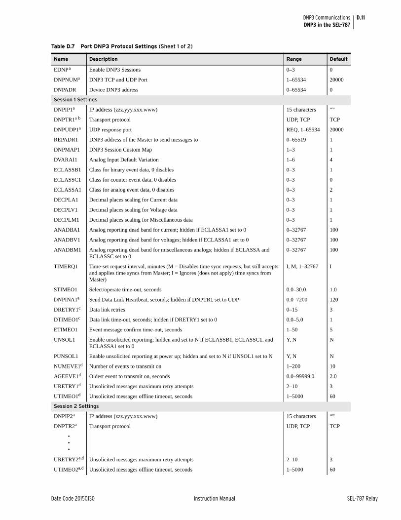
D.11
Date Code 20150130 Instruction Manual SEL-787 Relay
DNP3 CommunicationsDNP3 in the SEL-787
Table D.7 Port DNP3 Protocol Settings (Sheet 1 of 2)
Name Description Range Default
EDNPa Enable DNP3 Sessions 0–3 0
DNPNUMa DNP3 TCP and UDP Port 1–65534 20000
DNPADR Device DNP3 address 0–65534 0
Session 1 Settings
DNPIP1a IP address (zzz.yyy.xxx.www) 15 characters “”
DNPTR1a b Transport protocol UDP, TCP TCP
DNPUDP1a UDP response port REQ, 1–65534 20000
REPADR1 DNP3 address of the Master to send messages to 0–65519 1
DNPMAP1 DNP3 Session Custom Map 1–3 1
DVARAI1 Analog Input Default Variation 1–6 4
ECLASSB1 Class for binary event data, 0 disables 0–3 1
ECLASSC1 Class for counter event data, 0 disables 0–3 0
ECLASSA1 Class for analog event data, 0 disables 0–3 2
DECPLA1 Decimal places scaling for Current data 0–3 1
DECPLV1 Decimal places scaling for Voltage data 0–3 1
DECPLM1 Decimal places scaling for Miscellaneous data 0–3 1
ANADBA1 Analog reporting dead band for current; hidden if ECLASSA1 set to 0 0–32767 100
ANADBV1 Analog reporting dead band for voltages; hidden if ECLASSA1 set to 0 0–32767 100
ANADBM1 Analog reporting dead band for miscellaneous analogs; hidden if ECLASSA and ECLASSC set to 0
0–32767 100
TIMERQ1 Time-set request interval, minutes (M = Disables time sync requests, but still accepts and applies time syncs from Master; I = Ignores (does not apply) time syncs from Master)
I, M, 1–32767 I
STIMEO1 Select/operate time-out, seconds 0.0–30.0 1.0
DNPINA1a Send Data Link Heartbeat, seconds; hidden if DNPTR1 set to UDP 0.0–7200 120
DRETRY1c Data link retries 0–15 3
DTIMEO1c Data link time-out, seconds; hidden if DRETRY1 set to 0 0.0–5.0 1
ETIMEO1 Event message confirm time-out, seconds 1–50 5
UNSOL1 Enable unsolicited reporting; hidden and set to N if ECLASSB1, ECLASSC1, and ECLASSA1 set to 0
Y, N N
PUNSOL1 Enable unsolicited reporting at power up; hidden and set to N if UNSOL1 set to N Y, N N
NUMEVE1d Number of events to transmit on 1–200 10
AGEEVE1d Oldest event to transmit on, seconds 0.0–99999.0 2.0
URETRY1d Unsolicited messages maximum retry attempts 2–10 3
UTIMEO1d Unsolicited messages offline timeout, seconds 1–5000 60
Session 2 Settings
DNPIP2a IP address (zzz.yyy.xxx.www) 15 characters “”
DNPTR2a Transport protocol UDP, TCP TCP
•••
URETRY2a,d Unsolicited messages maximum retry attempts 2–10 3
UTIMEO2a,d Unsolicited messages offline timeout, seconds 1–5000 60
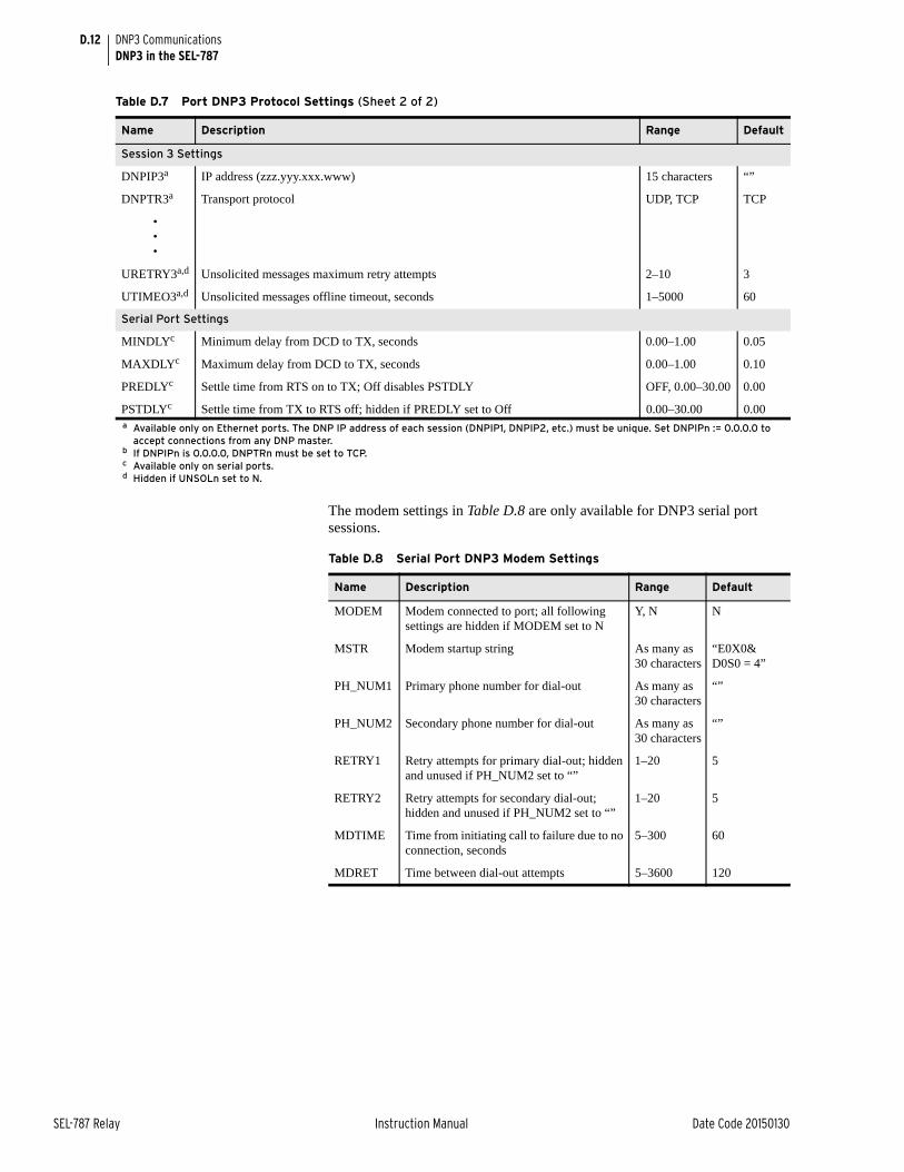
D.12
SEL-787 Relay Instruction Manual Date Code 20150130
DNP3 CommunicationsDNP3 in the SEL-787
The modem settings in Table D.8 are only available for DNP3 serial port sessions.
Session 3 Settings
DNPIP3a IP address (zzz.yyy.xxx.www) 15 characters “”
DNPTR3a Transport protocol UDP, TCP TCP
•••
URETRY3a,d Unsolicited messages maximum retry attempts 2–10 3
UTIMEO3a,d Unsolicited messages offline timeout, seconds 1–5000 60
Serial Port Settings
MINDLYc Minimum delay from DCD to TX, seconds 0.00–1.00 0.05
MAXDLYc Maximum delay from DCD to TX, seconds 0.00–1.00 0.10
PREDLYc Settle time from RTS on to TX; Off disables PSTDLY OFF, 0.00–30.00 0.00
PSTDLYc Settle time from TX to RTS off; hidden if PREDLY set to Off 0.00–30.00 0.00a Available only on Ethernet ports. The DNP IP address of each session (DNPIP1, DNPIP2, etc.) must be unique. Set DNPIPn := 0.0.0.0 to
accept connections from any DNP master.b If DNPIPn is 0.0.0.0, DNPTRn must be set to TCP.c Available only on serial ports.d Hidden if UNSOLn set to N.
Table D.7 Port DNP3 Protocol Settings (Sheet 2 of 2)
Name Description Range Default
Table D.8 Serial Port DNP3 Modem Settings
Name Description Range Default
MODEM Modem connected to port; all following settings are hidden if MODEM set to N
Y, N N
MSTR Modem startup string As many as 30 characters
“E0X0& D0S0 = 4”
PH_NUM1 Primary phone number for dial-out As many as 30 characters
“”
PH_NUM2 Secondary phone number for dial-out As many as 30 characters
“”
RETRY1 Retry attempts for primary dial-out; hidden and unused if PH_NUM2 set to “”
1–20 5
RETRY2 Retry attempts for secondary dial-out; hidden and unused if PH_NUM2 set to “”
1–20 5
MDTIME Time from initiating call to failure due to no connection, seconds
5–300 60
MDRET Time between dial-out attempts 5–3600 120
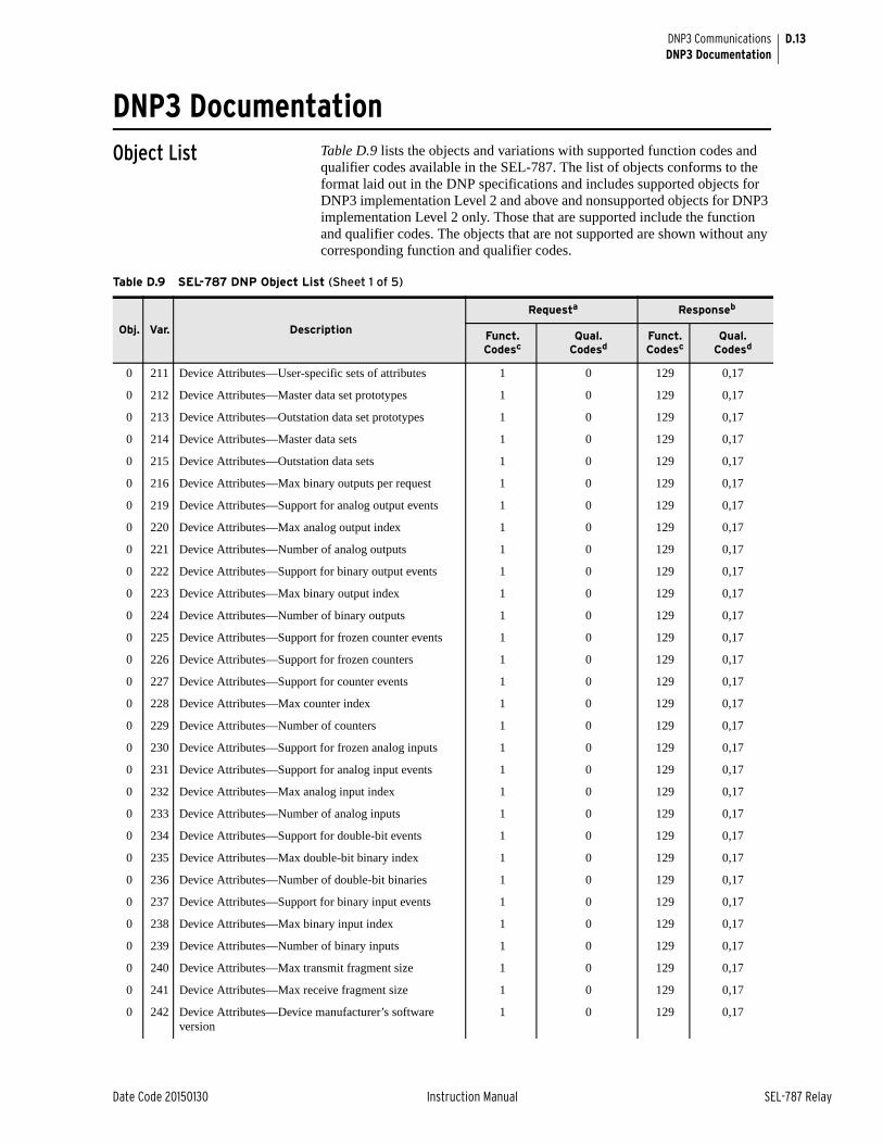
D.13
Date Code 20150130 Instruction Manual SEL-787 Relay
DNP3 CommunicationsDNP3 Documentation
DNP3 DocumentationObject List Table D.9 lists the objects and variations with supported function codes and
qualifier codes available in the SEL-787. The list of objects conforms to the format laid out in the DNP specifications and includes supported objects for DNP3 implementation Level 2 and above and nonsupported objects for DNP3 implementation Level 2 only. Those that are supported include the function and qualifier codes. The objects that are not supported are shown without any corresponding function and qualifier codes.
Table D.9 SEL-787 DNP Object List (Sheet 1 of 5)
Obj. Var. Description
Requesta Responseb
Funct. Codesc
Qual. Codesd
Funct. Codesc
Qual. Codesd
0 211 Device Attributes—User-specific sets of attributes 1 0 129 0,17
0 212 Device Attributes—Master data set prototypes 1 0 129 0,17
0 213 Device Attributes—Outstation data set prototypes 1 0 129 0,17
0 214 Device Attributes—Master data sets 1 0 129 0,17
0 215 Device Attributes—Outstation data sets 1 0 129 0,17
0 216 Device Attributes—Max binary outputs per request 1 0 129 0,17
0 219 Device Attributes—Support for analog output events 1 0 129 0,17
0 220 Device Attributes—Max analog output index 1 0 129 0,17
0 221 Device Attributes—Number of analog outputs 1 0 129 0,17
0 222 Device Attributes—Support for binary output events 1 0 129 0,17
0 223 Device Attributes—Max binary output index 1 0 129 0,17
0 224 Device Attributes—Number of binary outputs 1 0 129 0,17
0 225 Device Attributes—Support for frozen counter events 1 0 129 0,17
0 226 Device Attributes—Support for frozen counters 1 0 129 0,17
0 227 Device Attributes—Support for counter events 1 0 129 0,17
0 228 Device Attributes—Max counter index 1 0 129 0,17
0 229 Device Attributes—Number of counters 1 0 129 0,17
0 230 Device Attributes—Support for frozen analog inputs 1 0 129 0,17
0 231 Device Attributes—Support for analog input events 1 0 129 0,17
0 232 Device Attributes—Max analog input index 1 0 129 0,17
0 233 Device Attributes—Number of analog inputs 1 0 129 0,17
0 234 Device Attributes—Support for double-bit events 1 0 129 0,17
0 235 Device Attributes—Max double-bit binary index 1 0 129 0,17
0 236 Device Attributes—Number of double-bit binaries 1 0 129 0,17
0 237 Device Attributes—Support for binary input events 1 0 129 0,17
0 238 Device Attributes—Max binary input index 1 0 129 0,17
0 239 Device Attributes—Number of binary inputs 1 0 129 0,17
0 240 Device Attributes—Max transmit fragment size 1 0 129 0,17
0 241 Device Attributes—Max receive fragment size 1 0 129 0,17
0 242 Device Attributes—Device manufacturer’s software version
1 0 129 0,17
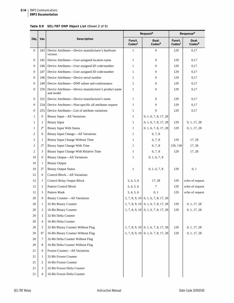
D.14
SEL-787 Relay Instruction Manual Date Code 20150130
DNP3 CommunicationsDNP3 Documentation
0 243 Device Attributes—Device manufacturer’s hardware version
1 0 129 0,17
0 245 Device Attributes—User-assigned location name 1 0 129 0,17
0 246 Device Attributes—User assigned ID code/number 1 0 129 0,17
0 247 Device Attributes—User assigned ID code/number 1 0 129 0,17
0 248 Device Attributes—Device serial number 1 0 129 0,17
0 249 Device Attributes—DNP subset and conformance 1 0 129 0,17
0 250 Device Attributes—Device manufacturer’s product name and model
1 0 129 0,17
0 252 Device Attributes—Device manufacturer's name 1 0 129 0,17
0 254 Device Attributes—Non-specific all attributes request 1 0 129 0,17
0 255 Device Attributes—List of attribute variations 1 0 129 0,17
1 0 Binary Input—All Variations 1 0, 1, 6, 7, 8, 17, 28
1 1 Binary Input 1 0, 1, 6, 7, 8, 17, 28 129 0, 1, 17, 28
1 2e Binary Input With Status 1 0, 1, 6, 7, 8, 17, 28 129 0, 1, 17, 28
2 0 Binary Input Change—All Variations 1 6, 7, 8
2 1 Binary Input Change Without Time 1 6, 7, 8 129 17, 28
2 2e Binary Input Change With Time 1 6, 7, 8 129, 130 17, 28
2 3 Binary Input Change With Relative Time 1 6, 7, 8 129 17, 28
10 0 Binary Output—All Variations 1 0, 1, 6, 7, 8
10 1 Binary Output
10 2e Binary Output Status 1 0, 1, 6, 7, 8 129 0, 1
12 0 Control Block—All Variations
12 1 Control Relay Output Block 3, 4, 5, 6 17, 28 129 echo of request
12 2 Pattern Control Block 3, 4, 5, 6 7 129 echo of request
12 3 Pattern Mask 3, 4, 5, 6 0, 1 129 echo of request
20 0 Binary Counter—All Variations 1, 7, 8, 9, 10 0, 1, 6, 7, 8, 17, 28
20 1 32-Bit Binary Counter 1, 7, 8, 9, 10 0, 1, 6, 7, 8, 17, 28 129 0, 1, 17, 28
20 2 16-Bit Binary Counter 1, 7, 8, 9, 10 0, 1, 6, 7, 8, 17, 28 129 0, 1, 17, 28
20 3 32-Bit Delta Counter
20 4 16-Bit Delta Counter
20 5 32-Bit Binary Counter Without Flag 1, 7, 8, 9, 10 0, 1, 6, 7, 8, 17, 28 129 0, 1, 17, 28
20 6e 16-Bit Binary Counter Without Flag 1, 7, 8, 9, 10 0, 1, 6, 7, 8, 17, 28 129 0, 1, 17, 28
20 7 32-Bit Delta Counter Without Flag
20 8 16-Bit Delta Counter Without Flag
21 0 Frozen Counter—All Variations
21 1 32-Bit Frozen Counter
21 2 16-Bit Frozen Counter
21 3 32-Bit Frozen Delta Counter
21 4 16-Bit Frozen Delta Counter
Table D.9 SEL-787 DNP Object List (Sheet 2 of 5)
Obj. Var. Description
Requesta Responseb
Funct. Codesc
Qual. Codesd
Funct. Codesc
Qual. Codesd
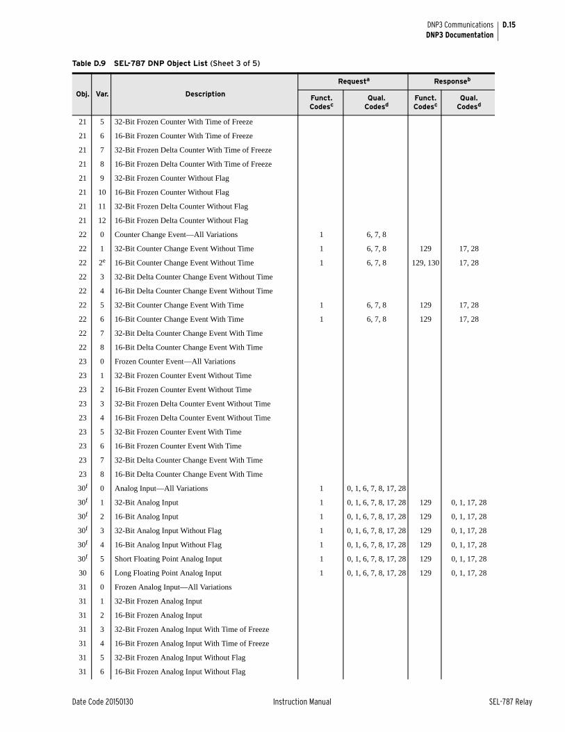
D.15
Date Code 20150130 Instruction Manual SEL-787 Relay
DNP3 CommunicationsDNP3 Documentation
21 5 32-Bit Frozen Counter With Time of Freeze
21 6 16-Bit Frozen Counter With Time of Freeze
21 7 32-Bit Frozen Delta Counter With Time of Freeze
21 8 16-Bit Frozen Delta Counter With Time of Freeze
21 9 32-Bit Frozen Counter Without Flag
21 10 16-Bit Frozen Counter Without Flag
21 11 32-Bit Frozen Delta Counter Without Flag
21 12 16-Bit Frozen Delta Counter Without Flag
22 0 Counter Change Event—All Variations 1 6, 7, 8
22 1 32-Bit Counter Change Event Without Time 1 6, 7, 8 129 17, 28
22 2e 16-Bit Counter Change Event Without Time 1 6, 7, 8 129, 130 17, 28
22 3 32-Bit Delta Counter Change Event Without Time
22 4 16-Bit Delta Counter Change Event Without Time
22 5 32-Bit Counter Change Event With Time 1 6, 7, 8 129 17, 28
22 6 16-Bit Counter Change Event With Time 1 6, 7, 8 129 17, 28
22 7 32-Bit Delta Counter Change Event With Time
22 8 16-Bit Delta Counter Change Event With Time
23 0 Frozen Counter Event—All Variations
23 1 32-Bit Frozen Counter Event Without Time
23 2 16-Bit Frozen Counter Event Without Time
23 3 32-Bit Frozen Delta Counter Event Without Time
23 4 16-Bit Frozen Delta Counter Event Without Time
23 5 32-Bit Frozen Counter Event With Time
23 6 16-Bit Frozen Counter Event With Time
23 7 32-Bit Delta Counter Change Event With Time
23 8 16-Bit Delta Counter Change Event With Time
30f 0 Analog Input—All Variations 1 0, 1, 6, 7, 8, 17, 28
30f 1 32-Bit Analog Input 1 0, 1, 6, 7, 8, 17, 28 129 0, 1, 17, 28
30f 2 16-Bit Analog Input 1 0, 1, 6, 7, 8, 17, 28 129 0, 1, 17, 28
30f 3 32-Bit Analog Input Without Flag 1 0, 1, 6, 7, 8, 17, 28 129 0, 1, 17, 28
30f 4 16-Bit Analog Input Without Flag 1 0, 1, 6, 7, 8, 17, 28 129 0, 1, 17, 28
30f 5 Short Floating Point Analog Input 1 0, 1, 6, 7, 8, 17, 28 129 0, 1, 17, 28
30 6 Long Floating Point Analog Input 1 0, 1, 6, 7, 8, 17, 28 129 0, 1, 17, 28
31 0 Frozen Analog Input—All Variations
31 1 32-Bit Frozen Analog Input
31 2 16-Bit Frozen Analog Input
31 3 32-Bit Frozen Analog Input With Time of Freeze
31 4 16-Bit Frozen Analog Input With Time of Freeze
31 5 32-Bit Frozen Analog Input Without Flag
31 6 16-Bit Frozen Analog Input Without Flag
Table D.9 SEL-787 DNP Object List (Sheet 3 of 5)
Obj. Var. Description
Requesta Responseb
Funct. Codesc
Qual. Codesd
Funct. Codesc
Qual. Codesd
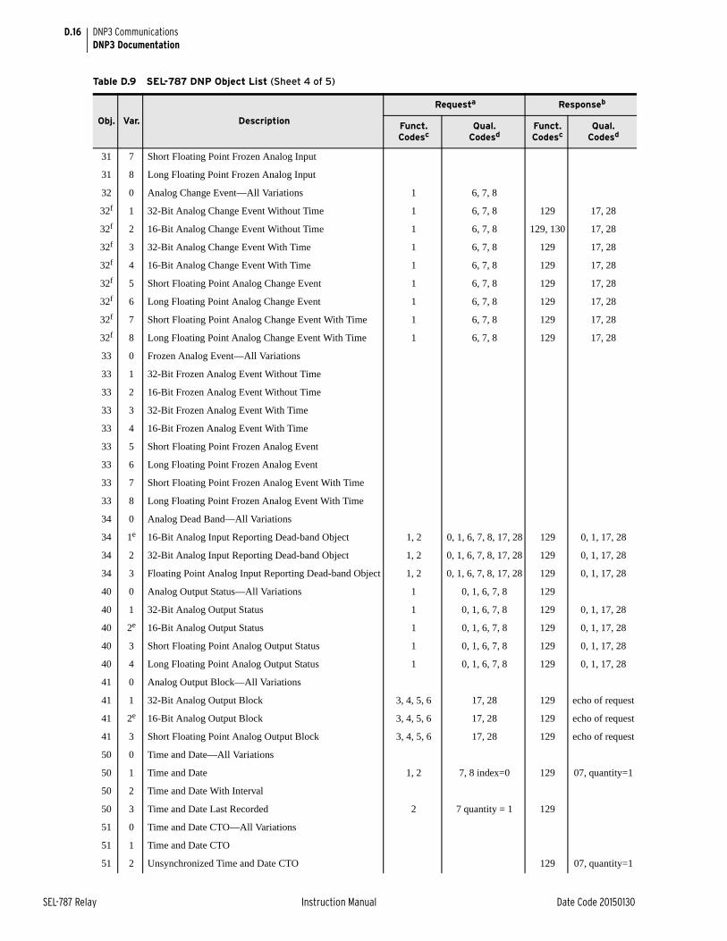
D.16
SEL-787 Relay Instruction Manual Date Code 20150130
DNP3 CommunicationsDNP3 Documentation
31 7 Short Floating Point Frozen Analog Input
31 8 Long Floating Point Frozen Analog Input
32 0 Analog Change Event—All Variations 1 6, 7, 8
32f 1 32-Bit Analog Change Event Without Time 1 6, 7, 8 129 17, 28
32f 2 16-Bit Analog Change Event Without Time 1 6, 7, 8 129, 130 17, 28
32f 3 32-Bit Analog Change Event With Time 1 6, 7, 8 129 17, 28
32f 4 16-Bit Analog Change Event With Time 1 6, 7, 8 129 17, 28
32f 5 Short Floating Point Analog Change Event 1 6, 7, 8 129 17, 28
32f 6 Long Floating Point Analog Change Event 1 6, 7, 8 129 17, 28
32f 7 Short Floating Point Analog Change Event With Time 1 6, 7, 8 129 17, 28
32f 8 Long Floating Point Analog Change Event With Time 1 6, 7, 8 129 17, 28
33 0 Frozen Analog Event—All Variations
33 1 32-Bit Frozen Analog Event Without Time
33 2 16-Bit Frozen Analog Event Without Time
33 3 32-Bit Frozen Analog Event With Time
33 4 16-Bit Frozen Analog Event With Time
33 5 Short Floating Point Frozen Analog Event
33 6 Long Floating Point Frozen Analog Event
33 7 Short Floating Point Frozen Analog Event With Time
33 8 Long Floating Point Frozen Analog Event With Time
34 0 Analog Dead Band—All Variations
34 1e 16-Bit Analog Input Reporting Dead-band Object 1, 2 0, 1, 6, 7, 8, 17, 28 129 0, 1, 17, 28
34 2 32-Bit Analog Input Reporting Dead-band Object 1, 2 0, 1, 6, 7, 8, 17, 28 129 0, 1, 17, 28
34 3 Floating Point Analog Input Reporting Dead-band Object 1, 2 0, 1, 6, 7, 8, 17, 28 129 0, 1, 17, 28
40 0 Analog Output Status—All Variations 1 0, 1, 6, 7, 8 129
40 1 32-Bit Analog Output Status 1 0, 1, 6, 7, 8 129 0, 1, 17, 28
40 2e 16-Bit Analog Output Status 1 0, 1, 6, 7, 8 129 0, 1, 17, 28
40 3 Short Floating Point Analog Output Status 1 0, 1, 6, 7, 8 129 0, 1, 17, 28
40 4 Long Floating Point Analog Output Status 1 0, 1, 6, 7, 8 129 0, 1, 17, 28
41 0 Analog Output Block—All Variations
41 1 32-Bit Analog Output Block 3, 4, 5, 6 17, 28 129 echo of request
41 2e 16-Bit Analog Output Block 3, 4, 5, 6 17, 28 129 echo of request
41 3 Short Floating Point Analog Output Block 3, 4, 5, 6 17, 28 129 echo of request
50 0 Time and Date—All Variations
50 1 Time and Date 1, 2 7, 8 index=0 129 07, quantity=1
50 2 Time and Date With Interval
50 3 Time and Date Last Recorded 2 7 quantity = 1 129
51 0 Time and Date CTO—All Variations
51 1 Time and Date CTO
51 2 Unsynchronized Time and Date CTO 129 07, quantity=1
Table D.9 SEL-787 DNP Object List (Sheet 4 of 5)
Obj. Var. Description
Requesta Responseb
Funct. Codesc
Qual. Codesd
Funct. Codesc
Qual. Codesd
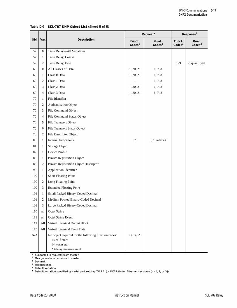
D.17
Date Code 20150130 Instruction Manual SEL-787 Relay
DNP3 CommunicationsDNP3 Documentation
52 0 Time Delay—All Variations
52 1 Time Delay, Coarse
52 2 Time Delay, Fine 129 7, quantity=1
60 0 All Classes of Data 1, 20, 21 6, 7, 8
60 1 Class 0 Data 1, 20, 21 6, 7, 8
60 2 Class 1 Data 1 6, 7, 8
60 3 Class 2 Data 1, 20, 21 6, 7, 8
60 4 Class 3 Data 1, 20, 21 6, 7, 8
70 1 File Identifier
70 2 Authentication Object
70 3 File Command Object
70 4 File Command Status Object
70 5 File Transport Object
70 6 File Transport Status Object
70 7 File Descriptor Object
80 1 Internal Indications 2 0, 1 index=7
81 1 Storage Object
82 1 Device Profile
83 1 Private Registration Object
83 2 Private Registration Object Descriptor
90 1 Application Identifier
100 1 Short Floating Point
100 2 Long Floating Point
100 3 Extended Floating Point
101 1 Small Packed Binary-Coded Decimal
101 2 Medium Packed Binary-Coded Decimal
101 3 Large Packed Binary-Coded Decimal
110 all Octet String
111 all Octet String Event
112 All Virtual Terminal Output Block
113 All Virtual Terminal Event Data
N/A No object required for the following function codes:
13 cold start
14 warm start
23 delay measurement
13, 14, 23
a Supported in requests from master.b May generate in response to master.c Decimal.d Hexadecimal.e Default variation.f Default variation specified by serial port setting DVARAI (or DVARAIn for Ethernet session n [n = 1, 2, or 3]).
Table D.9 SEL-787 DNP Object List (Sheet 5 of 5)
Obj. Var. Description
Requesta Responseb
Funct. Codesc
Qual. Codesd
Funct. Codesc
Qual. Codesd
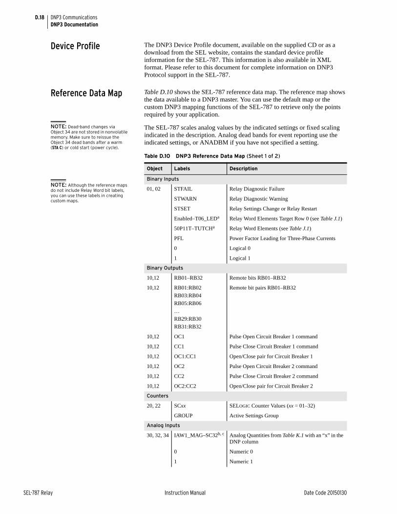
D.18
SEL-787 Relay Instruction Manual Date Code 20150130
DNP3 CommunicationsDNP3 Documentation
Device Profile The DNP3 Device Profile document, available on the supplied CD or as a download from the SEL website, contains the standard device profile information for the SEL-787. This information is also available in XML format. Please refer to this document for complete information on DNP3 Protocol support in the SEL-787.
Reference Data Map Table D.10 shows the SEL-787 reference data map. The reference map shows the data available to a DNP3 master. You can use the default map or the custom DNP3 mapping functions of the SEL-787 to retrieve only the points required by your application.
NOTE: Dead-band changes via Object 34 are not stored in nonvolatile memory. Make sure to reissue the Object 34 dead bands after a warm (STA C) or cold start (power cycle).
The SEL-787 scales analog values by the indicated settings or fixed scaling indicated in the description. Analog dead bands for event reporting use the indicated settings, or ANADBM if you have not specified a setting.
Table D.10 DNP3 Reference Data Map (Sheet 1 of 2)
Object Labels Description
Binary Inputs
01, 02 STFAIL Relay Diagnostic Failure
STWARN Relay Diagnostic Warning
STSET Relay Settings Change or Relay Restart
Enabled–T06_LEDa Relay Word Elements Target Row 0 (see Table J.1)
50P11T–TUTCHa Relay Word Elements (see Table J.1)
PFL Power Factor Leading for Three-Phase Currents
0 Logical 0
1 Logical 1
Binary Outputs
10,12 RB01–RB32 Remote bits RB01–RB32
10,12 RB01:RB02
RB03:RB04
RB05:RB06
…
RB29:RB30
RB31:RB32
Remote bit pairs RB01–RB32
10,12 OC1 Pulse Open Circuit Breaker 1 command
10,12 CC1 Pulse Close Circuit Breaker 1 command
10,12 OC1:CC1 Open/Close pair for Circuit Breaker 1
10,12 OC2 Pulse Open Circuit Breaker 2 command
10,12 CC2 Pulse Close Circuit Breaker 2 command
10,12 OC2:CC2 Open/Close pair for Circuit Breaker 2
Counters
20, 22 SCxx SELOGIC Counter Values (xx = 01–32)
GROUP Active Settings Group
Analog Inputs
30, 32, 34 IAW1_MAG–SC32b, c Analog Quantities from Table K.1 with an “x” in the DNP column
0 Numeric 0
1 Numeric 1
NOTE: Although the reference maps do not include Relay Word bit labels, you can use these labels in creating custom maps.
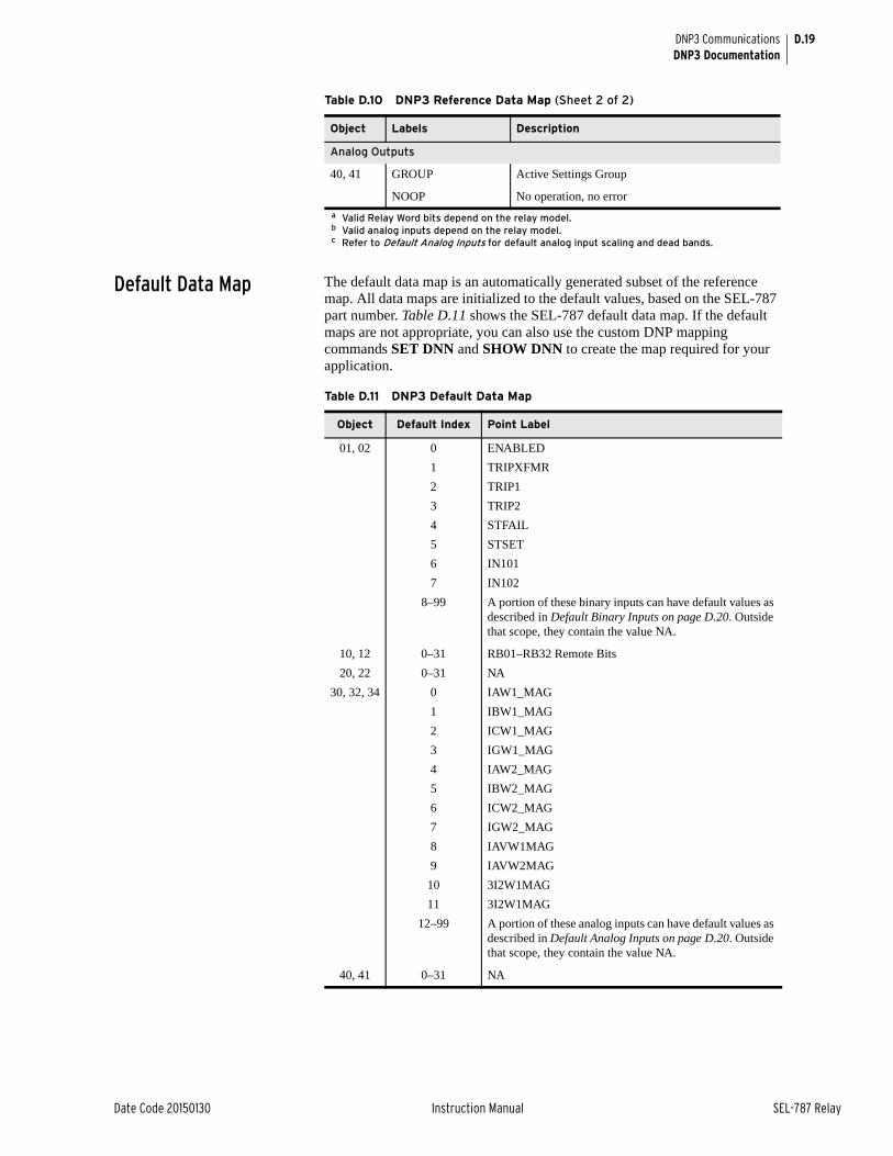
D.19
Date Code 20150130 Instruction Manual SEL-787 Relay
DNP3 CommunicationsDNP3 Documentation
Default Data Map The default data map is an automatically generated subset of the reference map. All data maps are initialized to the default values, based on the SEL-787 part number. Table D.11 shows the SEL-787 default data map. If the default maps are not appropriate, you can also use the custom DNP mapping commands SET DNN and SHOW DNN to create the map required for your application.
Analog Outputs
40, 41 GROUP Active Settings Group
NOOP No operation, no error
a Valid Relay Word bits depend on the relay model.b Valid analog inputs depend on the relay model.c Refer to Default Analog Inputs for default analog input scaling and dead bands.
Table D.10 DNP3 Reference Data Map (Sheet 2 of 2)
Object Labels Description
Table D.11 DNP3 Default Data Map
Object Default Index Point Label
01, 02 0 ENABLED
1 TRIPXFMR
2 TRIP1
3 TRIP2
4 STFAIL
5 STSET
6 IN101
7 IN102
8–99 A portion of these binary inputs can have default values as described in Default Binary Inputs on page D.20. Outside that scope, they contain the value NA.
10, 12 0–31 RB01–RB32 Remote Bits
20, 22 0–31 NA
30, 32, 34 0 IAW1_MAG
1 IBW1_MAG
2 ICW1_MAG
3 IGW1_MAG
4 IAW2_MAG
5 IBW2_MAG
6 ICW2_MAG
7 IGW2_MAG
8 IAVW1MAG
9 IAVW2MAG
10 3I2W1MAG
11 3I2W1MAG
12–99 A portion of these analog inputs can have default values as described in Default Analog Inputs on page D.20. Outside that scope, they contain the value NA.
40, 41 0–31 NA
D.20
SEL-787 Relay Instruction Manual Date Code 20150130
DNP3 CommunicationsDNP3 Documentation
Default Binary InputsThe SEL-787 dynamically creates the default Binary Input map after you issue an R_S command. The SEL-787 uses the Part Number to determine the presence of Digital Input cards in slots 3, 4, and 5. If present, each digital input point label, INx0y (where x is the slot number and y is the point), is added to the default map in numerical order.
Default Analog InputsThe SEL-787 dynamically creates the default Analog Input map after you issue an R_S command. The SEL-787 first checks for a voltage option in the part number, and if voltages are present, adds IN_MAG, VAB_MAG, VBC_MAG, VCA_MAG, VAVE_MAG, 3V2_MAG, P, Q, S, and PF to the default DNP map. The SEL-787 then uses the Part Number to determine the presence of Analog Input cards in slots 3, 4, and 5. If present, the SEL-787 adds each analog input point label, AIx0y (where x is the slot and y is the point number), to the default map in numerical order to the DNP map.
Device Attributes (Object 0)Table D.10 includes the supported Object 0 Device Attributes and variations. In response to Object 0 requests, the SEL-787 will send attributes that apply to that particular DNP3 session. Because the SEL-787 supports custom DNP3 maps, these values will likely be different for each session. The SEL-787 uses its internal settings for the following variations:
➤ Variation 242—FID string
➤ Variation 243—Part Number
➤ Variation 245—TID setting
➤ Variation 246—RID setting
➤ Variation 247—RID setting
➤ Variation 248—Serial Number
Variation 249 shall contain the DNP subset and conformance, “2:2009”. Variation 250 shall contain the product model, “SEL-787” and variation 252 shall contain “SEL”.
Binary InputsBinary Inputs (Objects 1 & 2) are supported as defined by Table D.11. The default variation for both static and event inputs is 2. Only the Read function code (1) is allowed with these objects. All variations are supported. Object 2, Variation 3 will be responded to, but will contain no data.
Binary Inputs are scanned approximately once per second to generate events. When time is reported with these event objects, it is the time at which the scanner observed the bit change. This can be significantly delayed from the time when the original source change occurred and should not be used for sequence-of-events determination. Binary inputs registered with SER are derived from the SER and carry the time stamp of actual occurrence. Some additional binary inputs are available only to DNP. For example, STWARN and STFAIL are derived from the diagnostic task data. Another binary input, STSET, is derived from the SER and carries the time stamp of actual occurrence. Static reads of this input will always show 0.
NOTE: Dead-band changes via Object 34 are stored in nonvolatile memory. Make sure to reissue the Object 34 dead bands after a warm (HIS C) or cold start (power cycle).
D.21
Date Code 20150130 Instruction Manual SEL-787 Relay
DNP3 CommunicationsDNP3 Documentation
Binary OutputsBinary Output status (Object 10, Variation 2) is supported. Static reads of points RB1–RB32, OC/CC respond with the on-line bit set and the state of the requested bit. Reads from control-only binary output points respond with the on-line bit set and a state of 0. The SEL-751 supports Control Relay Output Block objects (Object 12,Variation 1). The control relays correspond to the remote bits and other functions as shown previously. Each DNP Control message contains a Trip/Close code (TRIP, CLOSE, or NUL) and an Operation type (PULSE ON, LATCH ON, LATCH OFF, or NUL). The Trip/ Close code works with the Operation Type to produce set, clear, and pulse operations.
Control operations differ slightly for single-point controls compared to paired outputs. Paired outputs correspond to the complementary two-output model, and single-point controls follow the complementary latch or activation model. In the complementary two-output model, paired points only support Trip or Close operations, which, when issued, will Pulse On the first or second point in the pair, respectively. Latch commands and Pulse operations without a Trip code are not supported. You can cancel an operation in progress by issuing a NUL Trip/Close Code with a NUL Operation Type. Single output points support both Pulse and Latch operations. See Control Point Operation for details on control operations.
Use of the Status field is exactly as defined. All other fields are ignored. A pulse operation is asserted for a single processing interval. You should exercise caution if sending multiple remote bit pulses in a single message (i.e., point count > 1), because this can result in some of the pulse commands being ignored and the return of an already active status message. The SEL-787 will only honor the first ten points in an Object 12, Variation 1 request. Any additional points in the request will return the DNP3 status code TOO_MANY_OBJS.
The SEL-787 also supports Pattern Control Blocks (Object 12, Variations 2 and 3) to control multiple binary output points. Variation 2 defines the control type (Trip/Close, Set/Clear, or Pulse) and the range of points to operate. Variation 3 provides a pattern mask that indicates which points in that range should be operated. Object 12, Variations 2 and 3 define the entire control command: the DNP3 master must send both for a successful control. For example, the DNP3 master sends an Object 12, Variation 2 message to request a Trip of the range of indices 0–7. The DNP3 master then sends an Object 12, Variation 3 message with a hexadecimal value of “BB” as the pattern mask (converted to binary notation: 10111011). Read right to left in increasing bit order, the Pattern Block Control command will result in a Trip of indexes 0, 1, 3 to 5, and 7. Multiple binary output point control operations are not guaranteed to occur during the same processing interval.
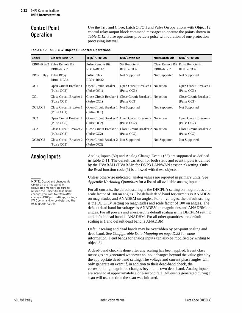
D.22
SEL-787 Relay Instruction Manual Date Code 20150130
DNP3 CommunicationsDNP3 Documentation
Control Point Operation
Use the Trip and Close, Latch On/Off and Pulse On operations with Object 12 control relay output block command messages to operate the points shown in Table D.12. Pulse operations provide a pulse with duration of one protection processing interval.
Analog Inputs Analog Inputs (30) and Analog Change Events (32) are supported as defined in Table D.11. The default variation for both static and event inputs is defined by the DVARAI1 (DVARAIn for DNP3 LAN/WAN session n) setting. Only the Read function code (1) is allowed with these objects.
Unless otherwise indicated, analog values are reported in primary units. See Appendix K: Analog Quantities for a list of all available analog inputs.
For all currents, the default scaling is the DECPLA setting on magnitudes and scale factor of 100 on angles. The default dead band for currents is ANADBV on magnitudes and ANADBM on angles. For all voltages, the default scaling is the DECPLV setting on magnitudes and scale factor of 100 on angles. The default dead band for voltages is ANADBV on magnitudes and ANADBM on angles. For all powers and energies, the default scaling is the DECPLM setting and default dead band is ANADBM. For all other quantities, the default scaling is 1 and default dead band is ANADBM.
Default scaling and dead bands may be overridden by per-point scaling and dead band. See Configurable Data Mapping on page D.23 for more information. Dead bands for analog inputs can also be modified by writing to object 34.
A dead-band check is done after any scaling has been applied. Event class messages are generated whenever an input changes beyond the value given by the appropriate dead-band setting. The voltage and current phase angles will only generate an event if, in addition to their dead-band check, the corresponding magnitude changes beyond its own dead band. Analog inputs are scanned at approximately a one-second rate. All events generated during a scan will use the time the scan was initiated.
Table D.12 SEL-787 Object 12 Control Operations
Label Close/Pulse On Trip/Pulse On Nul/Latch On Nul/Latch Off Nul/Pulse On
RB01–RB32 Pulse Remote Bit
RB01–RB32
Pulse Remote Bit
RB01–RB32
Set Remote Bit
RB01–RB32
Clear Remote Bit
RB01–RB32
Pulse Remote Bit
RB01–RB32
RBxx:RByy Pulse RByy
RB01–RB32
Pulse RBxx
RB01–RB32
Not Supported Not Supported Not Supported
OC1 Open Circuit Breaker 1
(Pulse OC1)
Open Circuit Breaker 1
(Pulse OC1)
Open Circuit Breaker 1
(Pulse OC1)
No action Open Circuit Breaker 1
(Pulse OC1)
CC1 Close Circuit Breaker 1
(Pulse CC1)
Close Circuit Breaker 1
(Pulse CC1)
Close Circuit Breaker 1
(Pulse CC1)
No action Close Circuit Breaker 1
(Pulse CC1)
OC1:CC1 Close Circuit Breaker 1
(Pulse CC1)
Open Circuit Breaker 1
(Pulse OC1)
Not Supported Not Supported Not Supported
OC2 Open Circuit Breaker 2
(Pulse OC2)
Open Circuit Breaker 2
(Pulse OC2)
Open Circuit Breaker 2
(Pulse OC2)
No action Open Circuit Breaker 2
(Pulse OC2)
CC2 Close Circuit Breaker 2
(Pulse CC2)
Close Circuit Breaker 2
(Pulse CC2)
Close Circuit Breaker 2
(Pulse CC2)
No action Close Circuit Breaker 2
(Pulse CC2)
OC2:CC2 Close Circuit Breaker 2
(Pulse CC2)
Open Circuit Breaker 2
(Pulse OC2)
Not Supported Not Supported Not Supported
NOTE: Dead-band changes via Object 34 are not stored in nonvolatile memory. Be sure to reissue the Object 34 dead-band changes you want to retain after changing DNP port settings, issuing a STA C command, or cold-starting the relay (power-cycle).
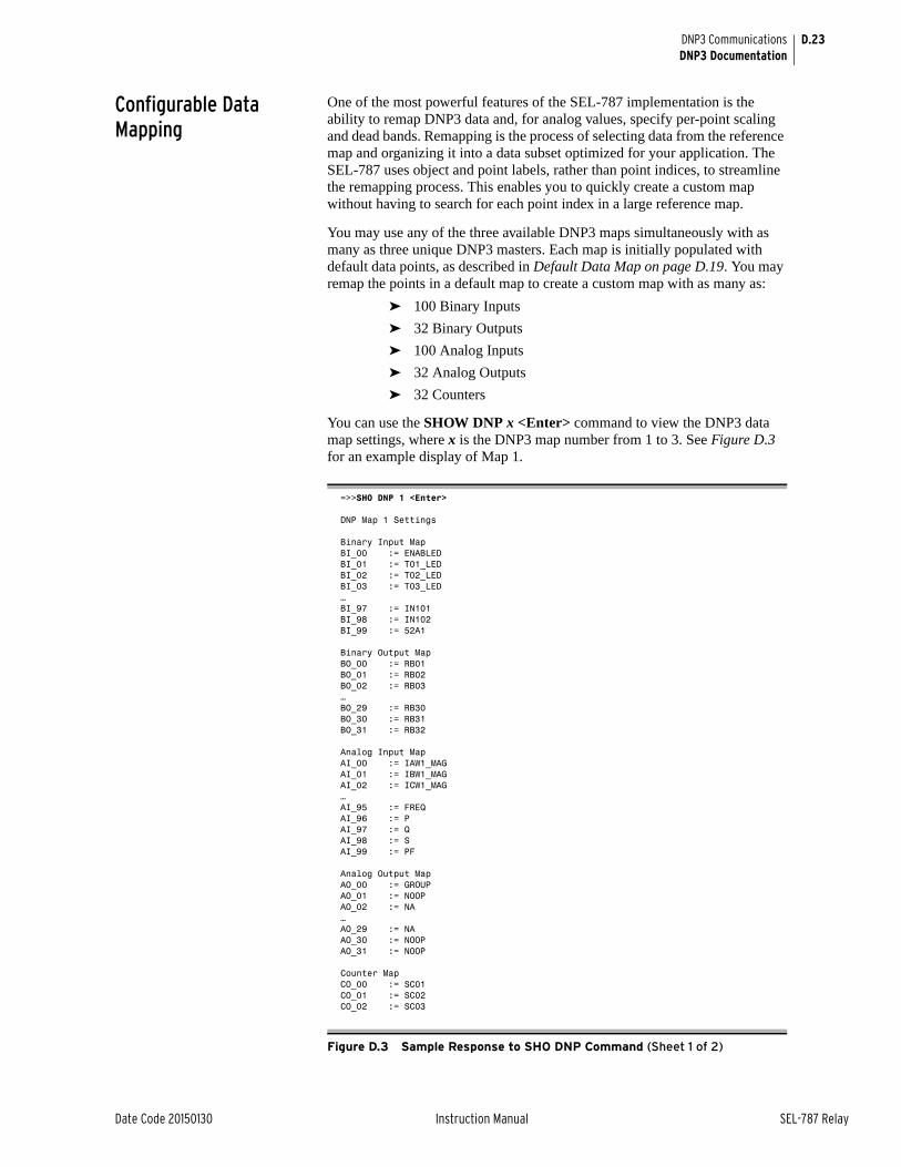
D.23
Date Code 20150130 Instruction Manual SEL-787 Relay
DNP3 CommunicationsDNP3 Documentation
Configurable Data Mapping
One of the most powerful features of the SEL-787 implementation is the ability to remap DNP3 data and, for analog values, specify per-point scaling and dead bands. Remapping is the process of selecting data from the reference map and organizing it into a data subset optimized for your application. The SEL-787 uses object and point labels, rather than point indices, to streamline the remapping process. This enables you to quickly create a custom map without having to search for each point index in a large reference map.
You may use any of the three available DNP3 maps simultaneously with as many as three unique DNP3 masters. Each map is initially populated with default data points, as described in Default Data Map on page D.19. You may remap the points in a default map to create a custom map with as many as:
➤ 100 Binary Inputs
➤ 32 Binary Outputs
➤ 100 Analog Inputs
➤ 32 Analog Outputs
➤ 32 Counters
You can use the SHOW DNP x <Enter> command to view the DNP3 data map settings, where x is the DNP3 map number from 1 to 3. See Figure D.3 for an example display of Map 1.
=>>SHO DNP 1 <Enter>
DNP Map 1 Settings
Binary Input MapBI_00 := ENABLEDBI_01 := T01_LEDBI_02 := T02_LEDBI_03 := T03_LED…BI_97 := IN101BI_98 := IN102BI_99 := 52A1
Binary Output MapBO_00 := RB01BO_01 := RB02BO_02 := RB03…BO_29 := RB30BO_30 := RB31BO_31 := RB32
Analog Input MapAI_00 := IAW1_MAGAI_01 := IBW1_MAGAI_02 := ICW1_MAG…AI_95 := FREQAI_96 := PAI_97 := QAI_98 := SAI_99 := PF
Analog Output MapAO_00 := GROUPAO_01 := NOOPAO_02 := NA…AO_29 := NAAO_30 := NOOPAO_31 := NOOP
Counter MapCO_00 := SC01CO_01 := SC02CO_02 := SC03
Figure D.3 Sample Response to SHO DNP Command (Sheet 1 of 2)
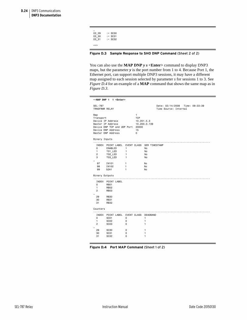
D.24
SEL-787 Relay Instruction Manual Date Code 20150130
DNP3 CommunicationsDNP3 Documentation
You can also use the MAP DNP y s <Enter> command to display DNP3 maps, but the parameter y is the port number from 1 to 4. Because Port 1, the Ethernet port, can support multiple DNP3 sessions, it may have a different map assigned to each session selected by parameter s for sessions 1 to 3. See Figure D.4 for an example of a MAP command that shows the same map as in Figure D.3.
…CO_29 := SC30CO_30 := SC31CO_31 := SC32
=>>
=>MAP DNP 1 1 <Enter>
SEL-787 Date: 02/14/2008 Time: 09:33:39TRNSFRMR RELAY Time Source: Internal
Map 1Transport TCPDevice IP Address 10.201.5.3Master IP Address 10.200.0.139Device DNP TCP and UDP Port 20000Device DNP Address 15Master DNP Address 0
Binary Inputs-------------------------------------------------------------------------------- INDEX POINT LABEL EVENT CLASS SER TIMESTAMP 0 ENABLED 1 No 1 T01_LED 1 No 2 T02_LED 1 No 3 T03_LED 1 No…
97 IN101 1 No98 IN102 1 No99 52A1 1 No
Binary Outputs-------------------------------------------------------------------------------- INDEX POINT LABEL 0 RB01 1 RB02 2 RB03… 29 RB30 30 RB31 31 RB32
Counters-------------------------------------------------------------------------------- INDEX POINT LABEL EVENT CLASS DEADBAND 0 SC01 0 1 1 SC02 0 1 2 SC03 0 1… 29 SC30 0 1 30 SC31 0 1 31 SC32 0 1
Figure D.4 Port MAP Command (Sheet 1 of 2)
Figure D.3 Sample Response to SHO DNP Command (Sheet 2 of 2)

D.25
Date Code 20150130 Instruction Manual SEL-787 Relay
DNP3 CommunicationsDNP3 Documentation
You can use the command SET DNP x, where x is the map number, to edit or create custom DNP3 data maps. You can also use ACSELERATOR QuickSet® SEL-5030 Software, which is recommended for this purpose.
Scaling factors allow you to overcome the limitations imposed by the integer nature of the default variations of Objects 30 and 32. For example, the device rounds a value of 11.4 amps to 11 amps. You may use scaling to include decimal point values by multiplying by a number larger than one. If you use 10 as a scaling factor, 11.4 amps will be transmitted as 114. You must divide the value by 10 in the master to see the original value including one decimal place.
You can also use scaling to avoid overflowing the 16-bit maximum integer value of 32767. For example, if you have a value that can reach 157834, you cannot send it using DNP3 16-bit analog object variations. You could use a scaling factor of 0.1 so that the maximum value reported is 15783. You can then multiply the value by 10 in the master to see a value of 157830. You will lose some precision as the last digit is rounded off in the scaling process, but you can transmit the scaled value using standard DNP3 Objects 30 and 32.
You can customize the DNP3 analog input map with per-point scaling, and dead-band settings. Per-point customization is not required, but class scaling (DECPLA, DECPLV, and DECPLM) and dead-band (ANADBA, ANADBV, and ANADBM) settings are applied to indices that do not have per-point entries. Unlike per-point scaling described above, class-level scaling is specified by an integer in the range 0–3 (inclusive), which indicates the number of decimal place shifts. In other words, you should select 0 to multiply by 1, 1 for 10, 2 for 100, or 3 for 1000.
If it is important to maintain tight data coherency (that is, all data read of a certain type was sampled or calculated at the same time), then you should group that data together within your custom map. For example, if you want all the Winding 1 currents to be coherent, you should group points IAW1_MAG,
Analog Inputs-------------------------------------------------------------------------------- INDEX POINT LABEL EVENT CLASS SCALE FACTOR DEADBAND 0 IAW1_MAG 2 10.0000 1000 1 IBW1_MAG 2 10.0000 1000 2 ICW1_MAG 2 10.0000 1000 3 IAW2_MAG 2 10.0000 1000 4 IBW2_MAG 2 10.0000 1000 5 ICW2_MAG 2 10.0000 1000 6 IGW1_MAG 2 10.0000 1000 7 IGW2_MAG 2 10.0000 1000 8 IN_MAG 2 10.0000 1000 9 IAVW1MAG 2 10.0000 1000 10 IAVW2MAG 2 10.0000 1000 11 3I2W1MAG 2 10.0000 1000 12 3I2W2MAG 2 10.0000 1000 13 FREQ 2 1.0000 100 14 VAB_MAG 2 10.0000 2000 15 VBC_MAG 2 10.0000 2000 16 VCA_MAG 2 10.0000 2000 17 VAVE_MAG 2 10.0000 2000 18 3V2_MAG 2 10.0000 2000…… 96 P 2 10.0000 100 97 Q 2 10.0000 100 98 S 2 10.0000 100 99 PF 2 10.0000 100
Analog Outputs--------------------------------------------------------------------------------
INDEX POINT LABEL 0 GROUP 1 NOOP
Figure D.4 Port MAP Command (Sheet 2 of 2)
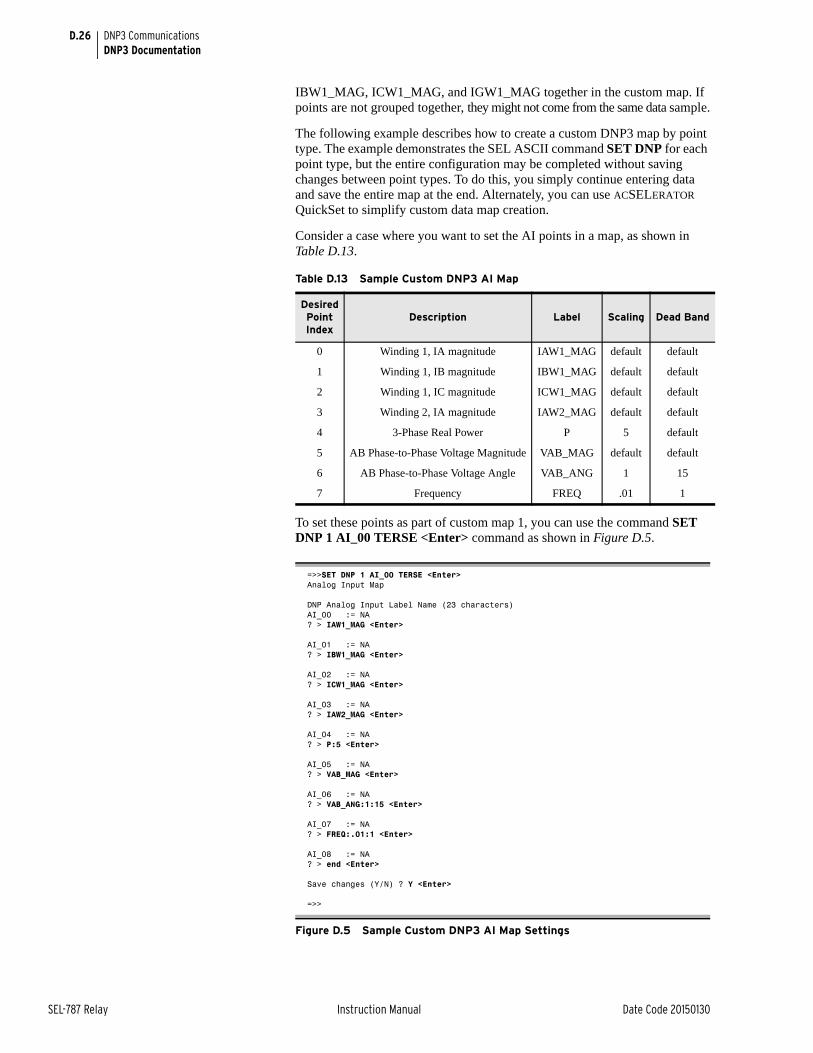
D.26
SEL-787 Relay Instruction Manual Date Code 20150130
DNP3 CommunicationsDNP3 Documentation
IBW1_MAG, ICW1_MAG, and IGW1_MAG together in the custom map. If points are not grouped together, they might not come from the same data sample.
The following example describes how to create a custom DNP3 map by point type. The example demonstrates the SEL ASCII command SET DNP for each point type, but the entire configuration may be completed without saving changes between point types. To do this, you simply continue entering data and save the entire map at the end. Alternately, you can use ACSELERATOR QuickSet to simplify custom data map creation.
Consider a case where you want to set the AI points in a map, as shown in Table D.13.
To set these points as part of custom map 1, you can use the command SET DNP 1 AI_00 TERSE <Enter> command as shown in Figure D.5.
Table D.13 Sample Custom DNP3 AI Map
Desired Point Index
Description Label Scaling Dead Band
0 Winding 1, IA magnitude IAW1_MAG default default
1 Winding 1, IB magnitude IBW1_MAG default default
2 Winding 1, IC magnitude ICW1_MAG default default
3 Winding 2, IA magnitude IAW2_MAG default default
4 3-Phase Real Power P 5 default
5 AB Phase-to-Phase Voltage Magnitude VAB_MAG default default
6 AB Phase-to-Phase Voltage Angle VAB_ANG 1 15
7 Frequency FREQ .01 1
=>>SET DNP 1 AI_00 TERSE <Enter>Analog Input Map
DNP Analog Input Label Name (23 characters)AI_00 := NA? > IAW1_MAG <Enter>
AI_01 := NA? > IBW1_MAG <Enter>
AI_02 := NA? > ICW1_MAG <Enter>
AI_03 := NA? > IAW2_MAG <Enter>
AI_04 := NA? > P:5 <Enter>
AI_05 := NA? > VAB_MAG <Enter>
AI_06 := NA? > VAB_ANG:1:15 <Enter>
AI_07 := NA? > FREQ:.01:1 <Enter>
AI_08 := NA? > end <Enter>
Save changes (Y/N) ? Y <Enter>
=>>
Figure D.5 Sample Custom DNP3 AI Map Settings

D.27
Date Code 20150130 Instruction Manual SEL-787 Relay
DNP3 CommunicationsDNP3 Documentation
You may also use ACSELERATOR QuickSet to enter the above AI map settings as shown in the screen capture in Figure D.6. You can enter scaling and dead-band settings in the same pop-up dialog used to select the AI point, as shown in Figure D.7.
Figure D.6 Analog Input Map Entry in ACSELERATOR QuickSet Software
Figure D.7 AI Point Label, Scaling and Dead Band in ACSELERATOR QuickSet Software
The SET DNP x CO_00 <Enter> command allows you to populate the DNP counter map with per-point dead bands. Entering these settings is similar to defining the analog input map settings.
You can use the command SET DNP x BO_00 TERSE <Enter> to change the binary output map x as shown in Figure D.8. You may populate the custom BO map with any of the 32 remote bits (RB01–RB32). You can define bit pairs in BO maps by including a colon (:) between the bit labels.
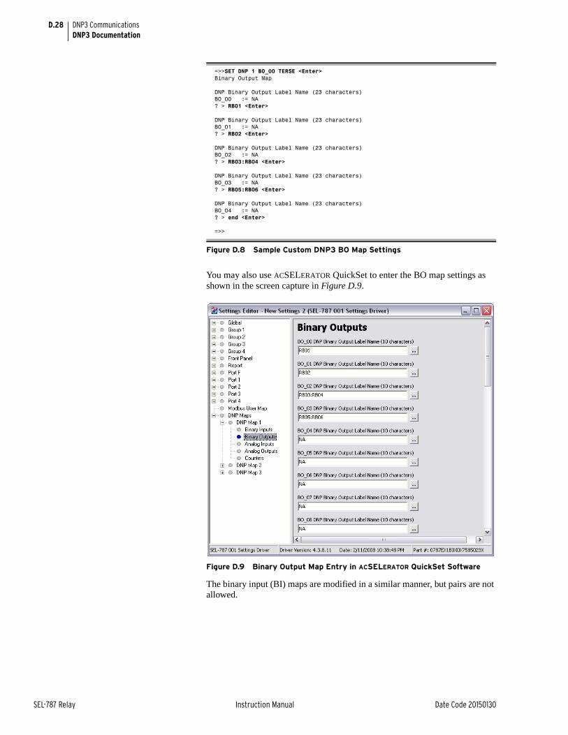
D.28
SEL-787 Relay Instruction Manual Date Code 20150130
DNP3 CommunicationsDNP3 Documentation
You may also use ACSELERATOR QuickSet to enter the BO map settings as shown in the screen capture in Figure D.9.
Figure D.9 Binary Output Map Entry in ACSELERATOR QuickSet Software
The binary input (BI) maps are modified in a similar manner, but pairs are not allowed.
=>>SET DNP 1 BO_00 TERSE <Enter>Binary Output Map
DNP Binary Output Label Name (23 characters)BO_00 := NA? > RB01 <Enter>
DNP Binary Output Label Name (23 characters)BO_01 := NA? > RB02 <Enter>
DNP Binary Output Label Name (23 characters)BO_02 := NA? > RB03:RB04 <Enter>
DNP Binary Output Label Name (23 characters)BO_03 := NA? > RB05:RB06 <Enter>
DNP Binary Output Label Name (23 characters)BO_04 := NA? > end <Enter>
=>>
Figure D.8 Sample Custom DNP3 BO Map Settings
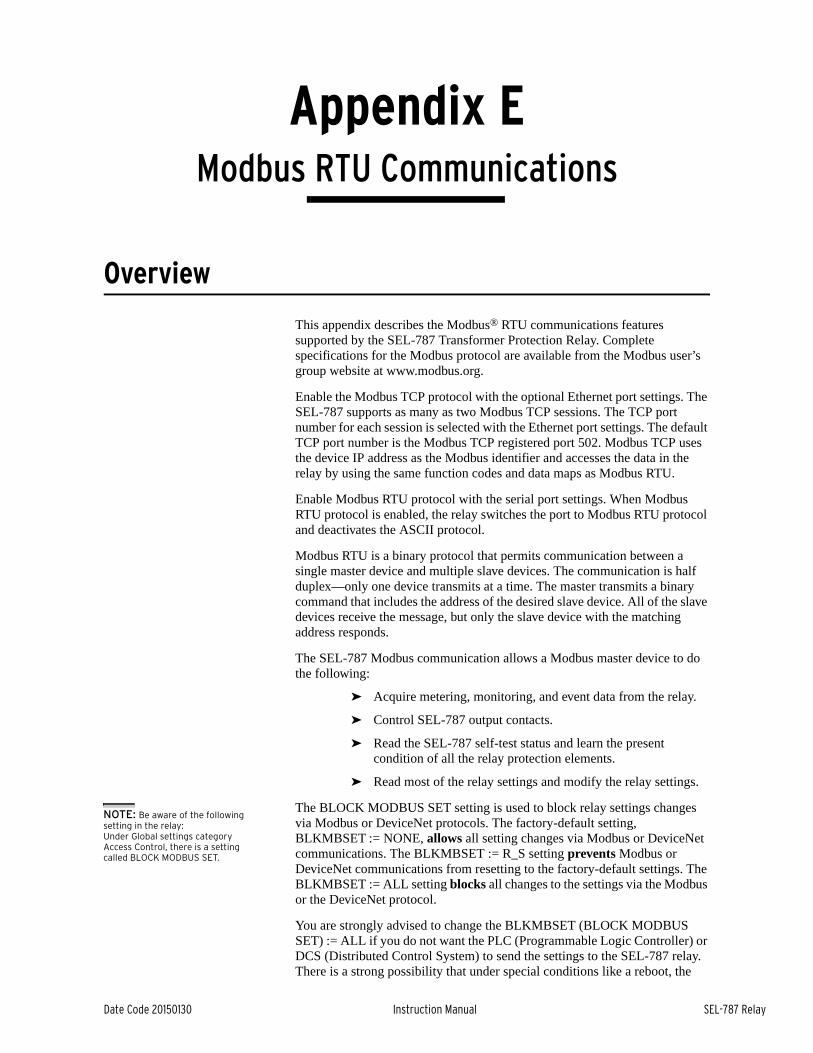
Date Code 20150130 Instruction Manual SEL-787 Relay
Appendix EModbus RTU Communications
Instruction Manual
Overview
This appendix describes the Modbus® RTU communications features supported by the SEL-787 Transformer Protection Relay. Complete specifications for the Modbus protocol are available from the Modbus user’s group website at www.modbus.org.
Enable the Modbus TCP protocol with the optional Ethernet port settings. The SEL-787 supports as many as two Modbus TCP sessions. The TCP port number for each session is selected with the Ethernet port settings. The default TCP port number is the Modbus TCP registered port 502. Modbus TCP uses the device IP address as the Modbus identifier and accesses the data in the relay by using the same function codes and data maps as Modbus RTU.
Enable Modbus RTU protocol with the serial port settings. When Modbus RTU protocol is enabled, the relay switches the port to Modbus RTU protocol and deactivates the ASCII protocol.
Modbus RTU is a binary protocol that permits communication between a single master device and multiple slave devices. The communication is half duplex—only one device transmits at a time. The master transmits a binary command that includes the address of the desired slave device. All of the slave devices receive the message, but only the slave device with the matching address responds.
The SEL-787 Modbus communication allows a Modbus master device to do the following:
➤ Acquire metering, monitoring, and event data from the relay.
➤ Control SEL-787 output contacts.
➤ Read the SEL-787 self-test status and learn the present condition of all the relay protection elements.
➤ Read most of the relay settings and modify the relay settings.
The BLOCK MODBUS SET setting is used to block relay settings changes via Modbus or DeviceNet protocols. The factory-default setting, BLKMBSET := NONE, allows all setting changes via Modbus or DeviceNet communications. The BLKMBSET := R_S setting prevents Modbus or DeviceNet communications from resetting to the factory-default settings. The BLKMBSET := ALL setting blocks all changes to the settings via the Modbus or the DeviceNet protocol.
You are strongly advised to change the BLKMBSET (BLOCK MODBUS SET) := ALL if you do not want the PLC (Programmable Logic Controller) or DCS (Distributed Control System) to send the settings to the SEL-787 relay. There is a strong possibility that under special conditions like a reboot, the
NOTE: Be aware of the following setting in the relay:Under Global settings category Access Control, there is a setting called BLOCK MODBUS SET.

E.2
SEL-787 Relay Instruction Manual Date Code 20150130
Modbus RTU CommunicationsCommunications Protocol
PLC/DCS will send default settings to the relay, overwriting the existing settings. To protect the existing settings under these conditions it is highly recommended to set the setting to "ALL."
Communications ProtocolModbus Queries Modbus RTU master devices initiate all exchanges by sending a query. The
query consists of the fields shown in Table E.1.
The SEL-787 SLAVEID setting defines the device address. Set this value to a unique number for each device on the Modbus network. For Modbus communication to operate properly, no two slave devices may have the same address.
The cyclical redundancy check detects errors in the received data. If an error is detected, the relay discards the packet.
Modbus Responses The slave device sends a response message after it performs the action the query specifies. If the slave cannot execute the query command for any reason, it sends an error response. Otherwise, the slave device response is formatted similarly to the query and includes the slave address, function code, data (if applicable), and a cyclical redundancy check value.
Supported Modbus Function Codes
The SEL-787 supports the Modbus function codes shown in Table E.2.
Table E.1 Modbus Query Fields
Field Number of Bytes
Slave Device Address 1 byte
Function Code 1 byte
Data Region 0–251 bytes
Cyclical Redundancy Check (CRC) 2 bytes
Table E.2 SEL-787 Modbus Function Codes
Codes Description
01h Read Discrete Output Coil Status
02h Read Discrete Input Status
03h Read Holding Registers
04h Read Input Registers
05h Force Single Coil
06h Preset Single Register
08h Diagnostic Command
10h Preset Multiple Registers
60h Read Parameter Information
61h Read Parameter Text
62h Read Enumeration Text
7Dh Encapsulate Modbus Packet With Control
7Eh NOP (can only be used with the 7Dh function)
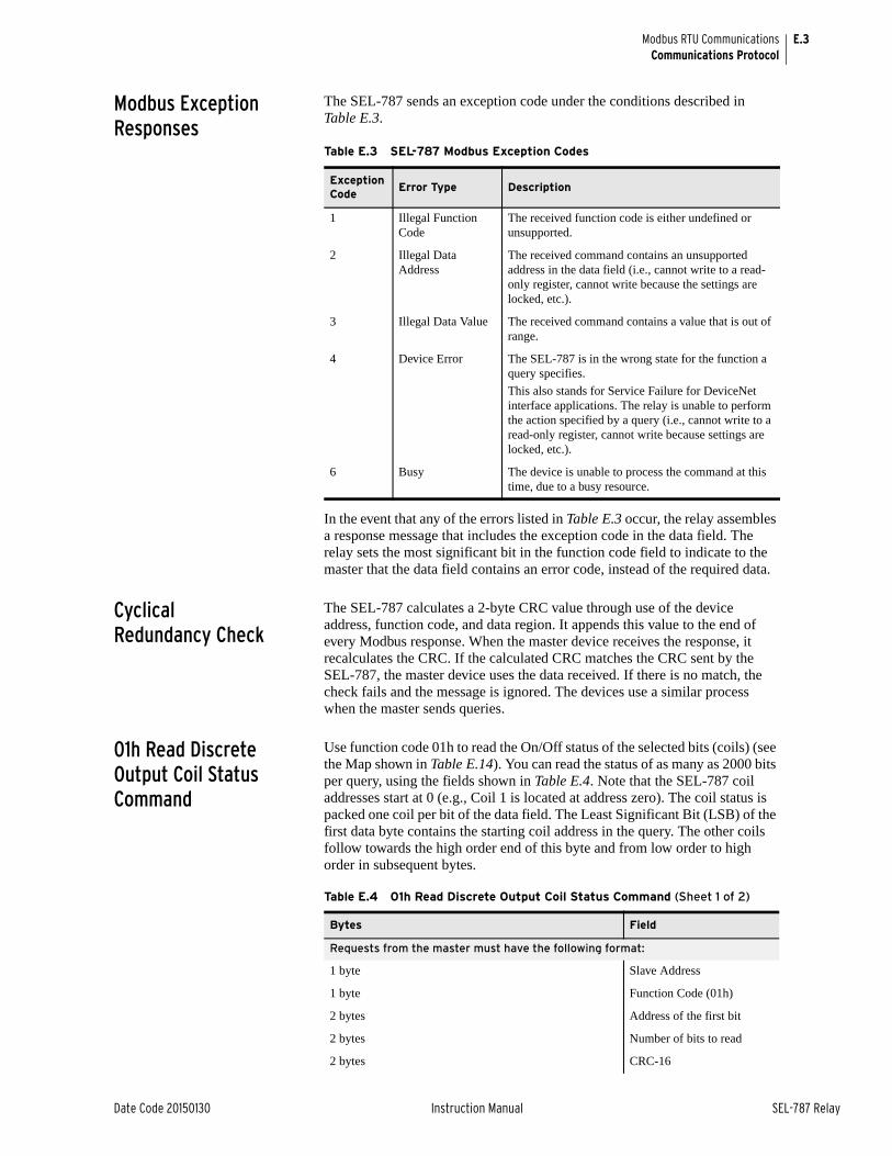
E.3
Date Code 20150130 Instruction Manual SEL-787 Relay
Modbus RTU CommunicationsCommunications Protocol
Modbus Exception Responses
The SEL-787 sends an exception code under the conditions described in Table E.3.
In the event that any of the errors listed in Table E.3 occur, the relay assembles a response message that includes the exception code in the data field. The relay sets the most significant bit in the function code field to indicate to the master that the data field contains an error code, instead of the required data.
Cyclical Redundancy Check
The SEL-787 calculates a 2-byte CRC value through use of the device address, function code, and data region. It appends this value to the end of every Modbus response. When the master device receives the response, it recalculates the CRC. If the calculated CRC matches the CRC sent by the SEL-787, the master device uses the data received. If there is no match, the check fails and the message is ignored. The devices use a similar process when the master sends queries.
01h Read Discrete Output Coil Status Command
Use function code 01h to read the On/Off status of the selected bits (coils) (see the Map shown in Table E.14). You can read the status of as many as 2000 bits per query, using the fields shown in Table E.4. Note that the SEL-787 coil addresses start at 0 (e.g., Coil 1 is located at address zero). The coil status is packed one coil per bit of the data field. The Least Significant Bit (LSB) of the first data byte contains the starting coil address in the query. The other coils follow towards the high order end of this byte and from low order to high order in subsequent bytes.
Table E.3 SEL-787 Modbus Exception Codes
Exception Code
Error Type Description
1 Illegal Function Code
The received function code is either undefined or unsupported.
2 Illegal Data Address
The received command contains an unsupported address in the data field (i.e., cannot write to a read-only register, cannot write because the settings are locked, etc.).
3 Illegal Data Value The received command contains a value that is out of range.
4 Device Error The SEL-787 is in the wrong state for the function a query specifies.
This also stands for Service Failure for DeviceNet interface applications. The relay is unable to perform the action specified by a query (i.e., cannot write to a read-only register, cannot write because settings are locked, etc.).
6 Busy The device is unable to process the command at this time, due to a busy resource.
Table E.4 01h Read Discrete Output Coil Status Command (Sheet 1 of 2)
Bytes Field
Requests from the master must have the following format:
1 byte Slave Address
1 byte Function Code (01h)
2 bytes Address of the first bit
2 bytes Number of bits to read
2 bytes CRC-16
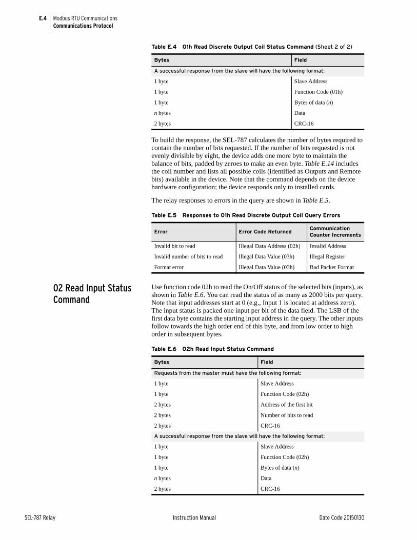
E.4
SEL-787 Relay Instruction Manual Date Code 20150130
Modbus RTU CommunicationsCommunications Protocol
To build the response, the SEL-787 calculates the number of bytes required to contain the number of bits requested. If the number of bits requested is not evenly divisible by eight, the device adds one more byte to maintain the balance of bits, padded by zeroes to make an even byte. Table E.14 includes the coil number and lists all possible coils (identified as Outputs and Remote bits) available in the device. Note that the command depends on the device hardware configuration; the device responds only to installed cards.
The relay responses to errors in the query are shown in Table E.5.
02 Read Input Status Command
Use function code 02h to read the On/Off status of the selected bits (inputs), as shown in Table E.6. You can read the status of as many as 2000 bits per query. Note that input addresses start at 0 (e.g., Input 1 is located at address zero). The input status is packed one input per bit of the data field. The LSB of the first data byte contains the starting input address in the query. The other inputs follow towards the high order end of this byte, and from low order to high order in subsequent bytes.
A successful response from the slave will have the following format:
1 byte Slave Address
1 byte Function Code (01h)
1 byte Bytes of data (n)
n bytes Data
2 bytes CRC-16
Table E.5 Responses to 01h Read Discrete Output Coil Query Errors
Error Error Code ReturnedCommunication Counter Increments
Invalid bit to read Illegal Data Address (02h) Invalid Address
Invalid number of bits to read Illegal Data Value (03h) Illegal Register
Format error Illegal Data Value (03h) Bad Packet Format
Table E.4 01h Read Discrete Output Coil Status Command (Sheet 2 of 2)
Bytes Field
Table E.6 02h Read Input Status Command
Bytes Field
Requests from the master must have the following format:
1 byte Slave Address
1 byte Function Code (02h)
2 bytes Address of the first bit
2 bytes Number of bits to read
2 bytes CRC-16
A successful response from the slave will have the following format:
1 byte Slave Address
1 byte Function Code (02h)
1 byte Bytes of data (n)
n bytes Data
2 bytes CRC-16
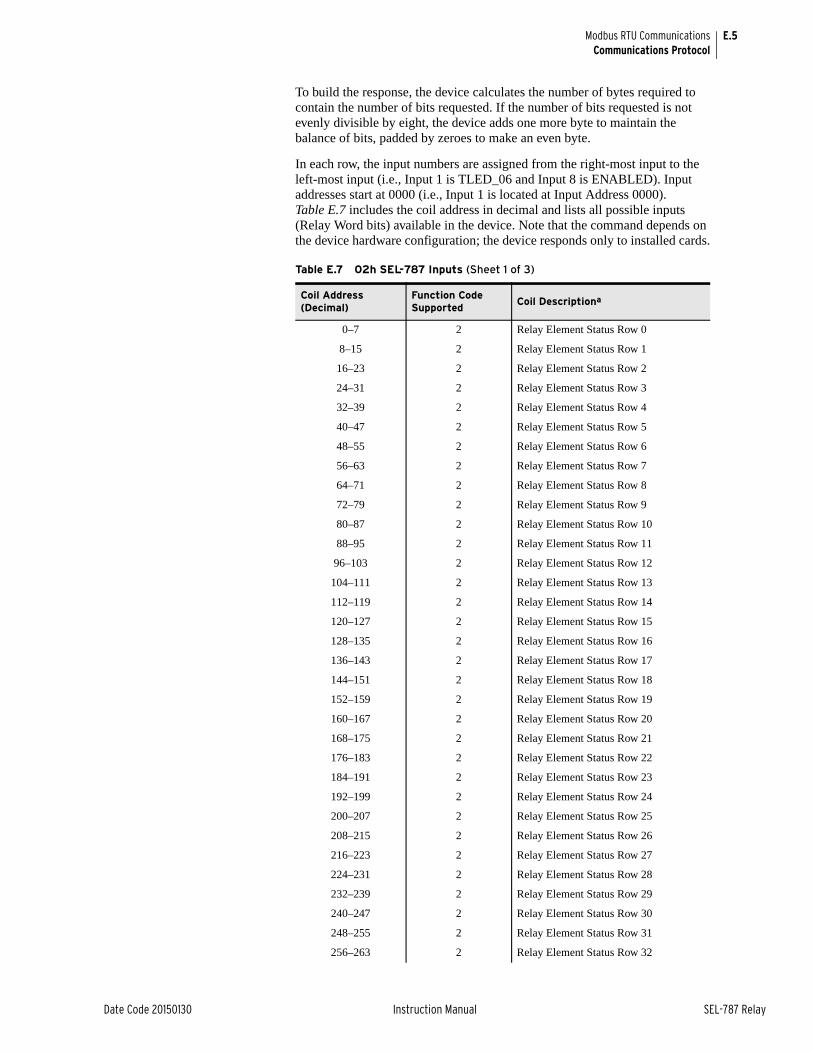
E.5
Date Code 20150130 Instruction Manual SEL-787 Relay
Modbus RTU CommunicationsCommunications Protocol
To build the response, the device calculates the number of bytes required to contain the number of bits requested. If the number of bits requested is not evenly divisible by eight, the device adds one more byte to maintain the balance of bits, padded by zeroes to make an even byte.
In each row, the input numbers are assigned from the right-most input to the left-most input (i.e., Input 1 is TLED_06 and Input 8 is ENABLED). Input addresses start at 0000 (i.e., Input 1 is located at Input Address 0000). Table E.7 includes the coil address in decimal and lists all possible inputs (Relay Word bits) available in the device. Note that the command depends on the device hardware configuration; the device responds only to installed cards.
Table E.7 02h SEL-787 Inputs (Sheet 1 of 3)
Coil Address (Decimal)
Function Code Supported
Coil Descriptiona
0–7 2 Relay Element Status Row 0
8–15 2 Relay Element Status Row 1
16–23 2 Relay Element Status Row 2
24–31 2 Relay Element Status Row 3
32–39 2 Relay Element Status Row 4
40–47 2 Relay Element Status Row 5
48–55 2 Relay Element Status Row 6
56–63 2 Relay Element Status Row 7
64–71 2 Relay Element Status Row 8
72–79 2 Relay Element Status Row 9
80–87 2 Relay Element Status Row 10
88–95 2 Relay Element Status Row 11
96–103 2 Relay Element Status Row 12
104–111 2 Relay Element Status Row 13
112–119 2 Relay Element Status Row 14
120–127 2 Relay Element Status Row 15
128–135 2 Relay Element Status Row 16
136–143 2 Relay Element Status Row 17
144–151 2 Relay Element Status Row 18
152–159 2 Relay Element Status Row 19
160–167 2 Relay Element Status Row 20
168–175 2 Relay Element Status Row 21
176–183 2 Relay Element Status Row 22
184–191 2 Relay Element Status Row 23
192–199 2 Relay Element Status Row 24
200–207 2 Relay Element Status Row 25
208–215 2 Relay Element Status Row 26
216–223 2 Relay Element Status Row 27
224–231 2 Relay Element Status Row 28
232–239 2 Relay Element Status Row 29
240–247 2 Relay Element Status Row 30
248–255 2 Relay Element Status Row 31
256–263 2 Relay Element Status Row 32
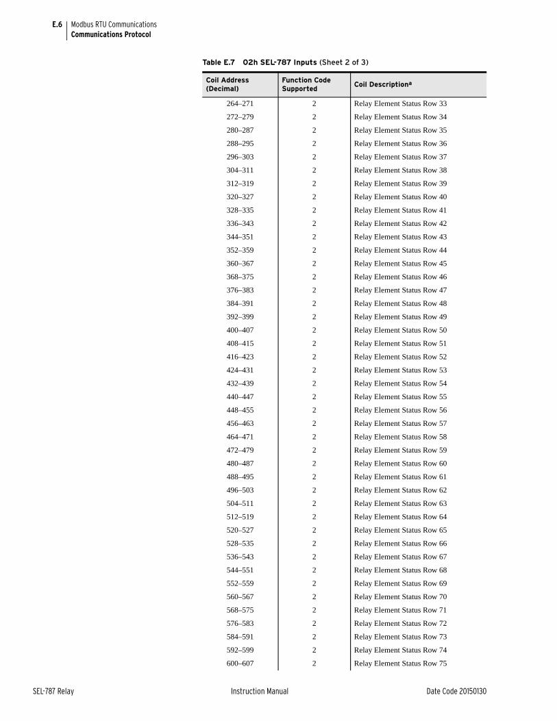
E.6
SEL-787 Relay Instruction Manual Date Code 20150130
Modbus RTU CommunicationsCommunications Protocol
264–271 2 Relay Element Status Row 33
272–279 2 Relay Element Status Row 34
280–287 2 Relay Element Status Row 35
288–295 2 Relay Element Status Row 36
296–303 2 Relay Element Status Row 37
304–311 2 Relay Element Status Row 38
312–319 2 Relay Element Status Row 39
320–327 2 Relay Element Status Row 40
328–335 2 Relay Element Status Row 41
336–343 2 Relay Element Status Row 42
344–351 2 Relay Element Status Row 43
352–359 2 Relay Element Status Row 44
360–367 2 Relay Element Status Row 45
368–375 2 Relay Element Status Row 46
376–383 2 Relay Element Status Row 47
384–391 2 Relay Element Status Row 48
392–399 2 Relay Element Status Row 49
400–407 2 Relay Element Status Row 50
408–415 2 Relay Element Status Row 51
416–423 2 Relay Element Status Row 52
424–431 2 Relay Element Status Row 53
432–439 2 Relay Element Status Row 54
440–447 2 Relay Element Status Row 55
448–455 2 Relay Element Status Row 56
456–463 2 Relay Element Status Row 57
464–471 2 Relay Element Status Row 58
472–479 2 Relay Element Status Row 59
480–487 2 Relay Element Status Row 60
488–495 2 Relay Element Status Row 61
496–503 2 Relay Element Status Row 62
504–511 2 Relay Element Status Row 63
512–519 2 Relay Element Status Row 64
520–527 2 Relay Element Status Row 65
528–535 2 Relay Element Status Row 66
536–543 2 Relay Element Status Row 67
544–551 2 Relay Element Status Row 68
552–559 2 Relay Element Status Row 69
560–567 2 Relay Element Status Row 70
568–575 2 Relay Element Status Row 71
576–583 2 Relay Element Status Row 72
584–591 2 Relay Element Status Row 73
592–599 2 Relay Element Status Row 74
600–607 2 Relay Element Status Row 75
Table E.7 02h SEL-787 Inputs (Sheet 2 of 3)
Coil Address (Decimal)
Function Code Supported
Coil Descriptiona
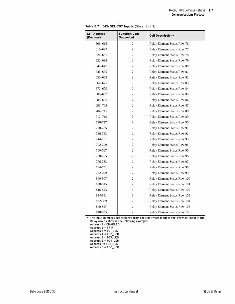
E.7
Date Code 20150130 Instruction Manual SEL-787 Relay
Modbus RTU CommunicationsCommunications Protocol
608–615 2 Relay Element Status Row 76
616–623 2 Relay Element Status Row 77
624–631 2 Relay Element Status Row 78
632–639 2 Relay Element Status Row 79
640–647 2 Relay Element Status Row 80
648–655 2 Relay Element Status Row 81
656–663 2 Relay Element Status Row 82
664–671 2 Relay Element Status Row 83
672–679 2 Relay Element Status Row 84
680–687 2 Relay Element Status Row 85
688–695 2 Relay Element Status Row 86
696–703 2 Relay Element Status Row 87
704–711 2 Relay Element Status Row 88
712–719 2 Relay Element Status Row 89
720-727 2 Relay Element Status Row 90
728-735 2 Relay Element Status Row 91
736-743 2 Relay Element Status Row 92
744-751 2 Relay Element Status Row 93
752-759 2 Relay Element Status Row 94
760-767 2 Relay Element Status Row 95
768-775 2 Relay Element Status Row 96
776-783 2 Relay Element Status Row 97
784-791 2 Relay Element Status Row 98
792-799 2 Relay Element Status Row 99
800-807 2 Relay Element Status Row 100
808-815 2 Relay Element Status Row 101
816-823 2 Relay Element Status Row 102
824-831 2 Relay Element Status Row 103
832-839 2 Relay Element Status Row 104
840-847 2 Relay Element Status Row 105
848-855 2 Relay Element Status Row 106
a The input numbers are assigned from the right-most input to the left-most input in the Relay row as show in the following example.Address 7 = ENABLEDAddress 6 = TRIPAddress 5 = T01_LEDAddress 4 = T02_LEDAddress 3 = T03_LEDAddress 2 = T04_LEDAddress 1 = T05_LEDAddress 0 = T06_LED
Table E.7 02h SEL-787 Inputs (Sheet 3 of 3)
Coil Address (Decimal)
Function Code Supported
Coil Descriptiona
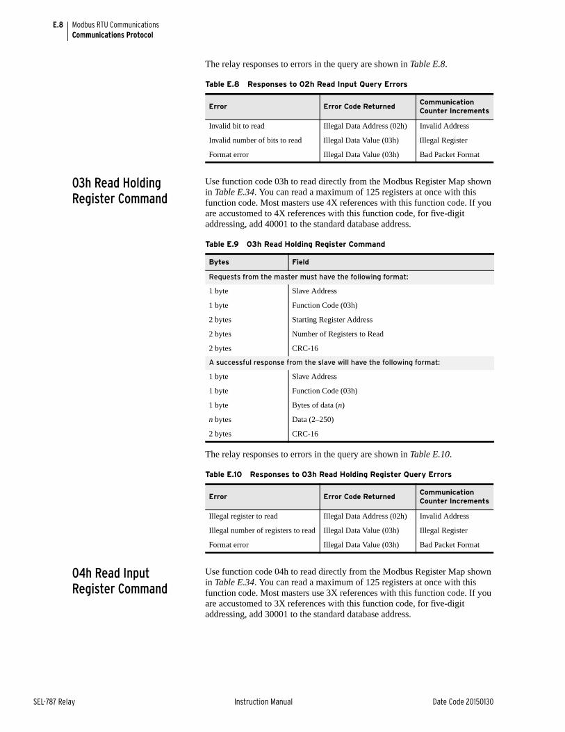
E.8
SEL-787 Relay Instruction Manual Date Code 20150130
Modbus RTU CommunicationsCommunications Protocol
The relay responses to errors in the query are shown in Table E.8.
03h Read Holding Register Command
Use function code 03h to read directly from the Modbus Register Map shown in Table E.34. You can read a maximum of 125 registers at once with this function code. Most masters use 4X references with this function code. If you are accustomed to 4X references with this function code, for five-digit addressing, add 40001 to the standard database address.
The relay responses to errors in the query are shown in Table E.10.
04h Read Input Register Command
Use function code 04h to read directly from the Modbus Register Map shown in Table E.34. You can read a maximum of 125 registers at once with this function code. Most masters use 3X references with this function code. If you are accustomed to 3X references with this function code, for five-digit addressing, add 30001 to the standard database address.
Table E.8 Responses to 02h Read Input Query Errors
Error Error Code ReturnedCommunication Counter Increments
Invalid bit to read Illegal Data Address (02h) Invalid Address
Invalid number of bits to read Illegal Data Value (03h) Illegal Register
Format error Illegal Data Value (03h) Bad Packet Format
Table E.9 03h Read Holding Register Command
Bytes Field
Requests from the master must have the following format:
1 byte Slave Address
1 byte Function Code (03h)
2 bytes Starting Register Address
2 bytes Number of Registers to Read
2 bytes CRC-16
A successful response from the slave will have the following format:
1 byte Slave Address
1 byte Function Code (03h)
1 byte Bytes of data (n)
n bytes Data (2–250)
2 bytes CRC-16
Table E.10 Responses to 03h Read Holding Register Query Errors
Error Error Code ReturnedCommunication Counter Increments
Illegal register to read Illegal Data Address (02h) Invalid Address
Illegal number of registers to read Illegal Data Value (03h) Illegal Register
Format error Illegal Data Value (03h) Bad Packet Format
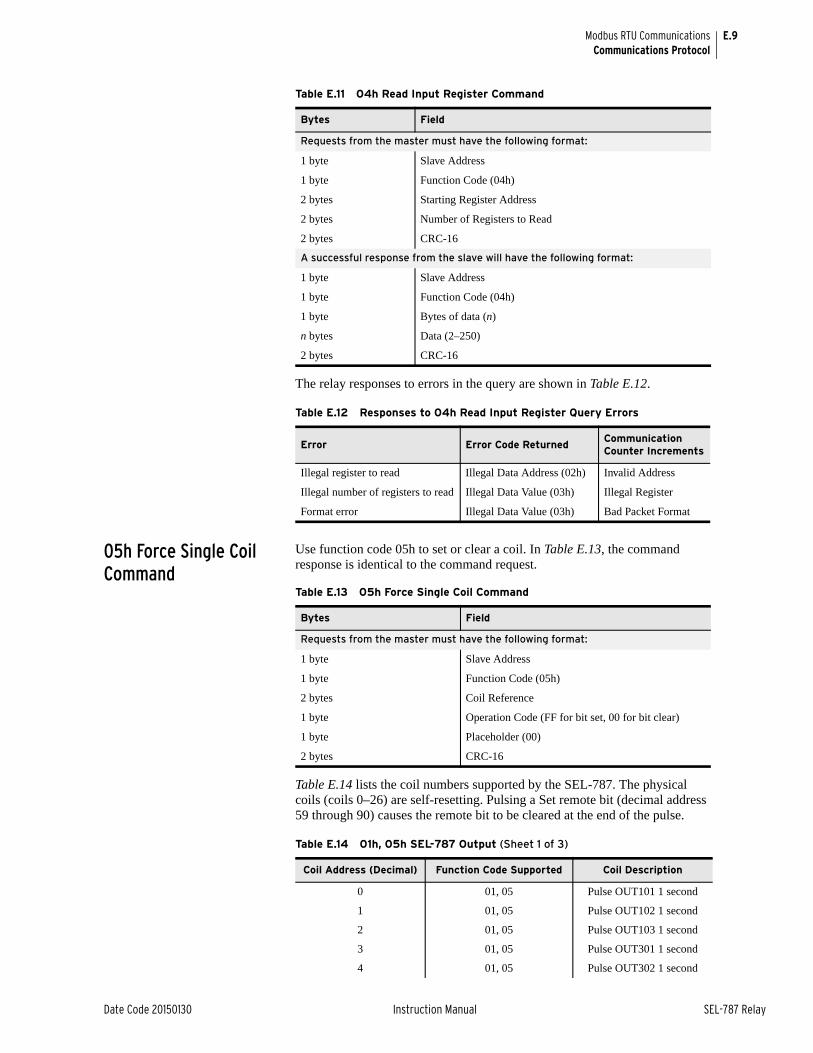
E.9
Date Code 20150130 Instruction Manual SEL-787 Relay
Modbus RTU CommunicationsCommunications Protocol
The relay responses to errors in the query are shown in Table E.12.
05h Force Single Coil Command
Use function code 05h to set or clear a coil. In Table E.13, the command response is identical to the command request.
Table E.14 lists the coil numbers supported by the SEL-787. The physical coils (coils 0–26) are self-resetting. Pulsing a Set remote bit (decimal address 59 through 90) causes the remote bit to be cleared at the end of the pulse.
Table E.11 04h Read Input Register Command
Bytes Field
Requests from the master must have the following format:
1 byte Slave Address
1 byte Function Code (04h)
2 bytes Starting Register Address
2 bytes Number of Registers to Read
2 bytes CRC-16
A successful response from the slave will have the following format:
1 byte Slave Address
1 byte Function Code (04h)
1 byte Bytes of data (n)
n bytes Data (2–250)
2 bytes CRC-16
Table E.12 Responses to 04h Read Input Register Query Errors
Error Error Code ReturnedCommunication Counter Increments
Illegal register to read Illegal Data Address (02h) Invalid Address
Illegal number of registers to read Illegal Data Value (03h) Illegal Register
Format error Illegal Data Value (03h) Bad Packet Format
Table E.13 05h Force Single Coil Command
Bytes Field
Requests from the master must have the following format:
1 byte Slave Address
1 byte Function Code (05h)
2 bytes Coil Reference
1 byte Operation Code (FF for bit set, 00 for bit clear)
1 byte Placeholder (00)
2 bytes CRC-16
Table E.14 01h, 05h SEL-787 Output (Sheet 1 of 3)
Coil Address (Decimal) Function Code Supported Coil Description
0 01, 05 Pulse OUT101 1 second
1 01, 05 Pulse OUT102 1 second
2 01, 05 Pulse OUT103 1 second
3 01, 05 Pulse OUT301 1 second
4 01, 05 Pulse OUT302 1 second
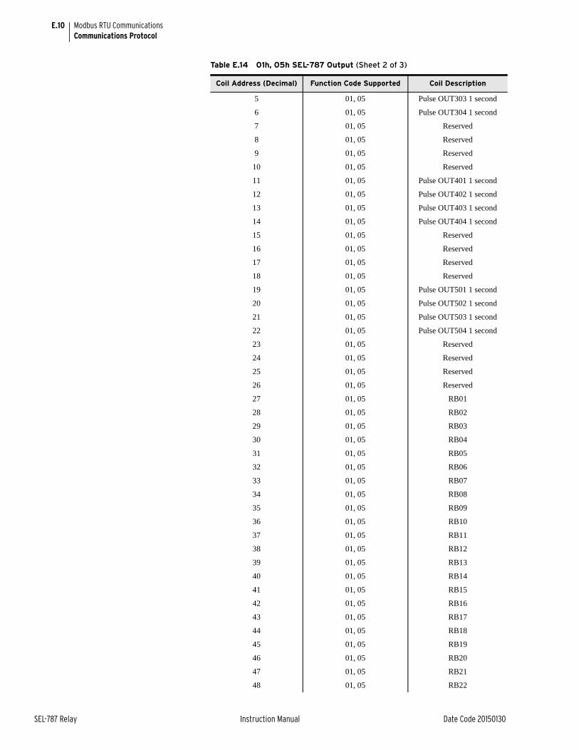
E.10
SEL-787 Relay Instruction Manual Date Code 20150130
Modbus RTU CommunicationsCommunications Protocol
5 01, 05 Pulse OUT303 1 second
6 01, 05 Pulse OUT304 1 second
7 01, 05 Reserved
8 01, 05 Reserved
9 01, 05 Reserved
10 01, 05 Reserved
11 01, 05 Pulse OUT401 1 second
12 01, 05 Pulse OUT402 1 second
13 01, 05 Pulse OUT403 1 second
14 01, 05 Pulse OUT404 1 second
15 01, 05 Reserved
16 01, 05 Reserved
17 01, 05 Reserved
18 01, 05 Reserved
19 01, 05 Pulse OUT501 1 second
20 01, 05 Pulse OUT502 1 second
21 01, 05 Pulse OUT503 1 second
22 01, 05 Pulse OUT504 1 second
23 01, 05 Reserved
24 01, 05 Reserved
25 01, 05 Reserved
26 01, 05 Reserved
27 01, 05 RB01
28 01, 05 RB02
29 01, 05 RB03
30 01, 05 RB04
31 01, 05 RB05
32 01, 05 RB06
33 01, 05 RB07
34 01, 05 RB08
35 01, 05 RB09
36 01, 05 RB10
37 01, 05 RB11
38 01, 05 RB12
39 01, 05 RB13
40 01, 05 RB14
41 01, 05 RB15
42 01, 05 RB16
43 01, 05 RB17
44 01, 05 RB18
45 01, 05 RB19
46 01, 05 RB20
47 01, 05 RB21
48 01, 05 RB22
Table E.14 01h, 05h SEL-787 Output (Sheet 2 of 3)
Coil Address (Decimal) Function Code Supported Coil Description
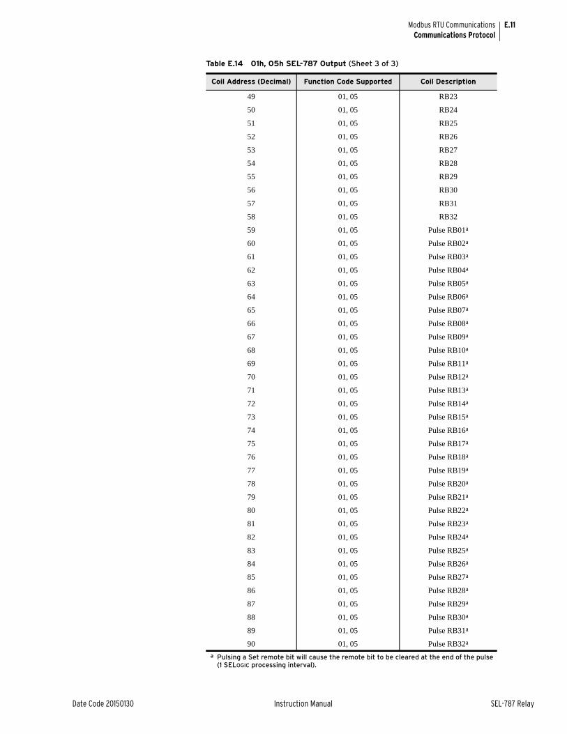
E.11
Date Code 20150130 Instruction Manual SEL-787 Relay
Modbus RTU CommunicationsCommunications Protocol
49 01, 05 RB23
50 01, 05 RB24
51 01, 05 RB25
52 01, 05 RB26
53 01, 05 RB27
54 01, 05 RB28
55 01, 05 RB29
56 01, 05 RB30
57 01, 05 RB31
58 01, 05 RB32
59 01, 05 Pulse RB01a
60 01, 05 Pulse RB02a
61 01, 05 Pulse RB03a
62 01, 05 Pulse RB04a
63 01, 05 Pulse RB05a
64 01, 05 Pulse RB06a
65 01, 05 Pulse RB07a
66 01, 05 Pulse RB08a
67 01, 05 Pulse RB09a
68 01, 05 Pulse RB10a
69 01, 05 Pulse RB11a
70 01, 05 Pulse RB12a
71 01, 05 Pulse RB13a
72 01, 05 Pulse RB14a
73 01, 05 Pulse RB15a
74 01, 05 Pulse RB16a
75 01, 05 Pulse RB17a
76 01, 05 Pulse RB18a
77 01, 05 Pulse RB19a
78 01, 05 Pulse RB20a
79 01, 05 Pulse RB21a
80 01, 05 Pulse RB22a
81 01, 05 Pulse RB23a
82 01, 05 Pulse RB24a
83 01, 05 Pulse RB25a
84 01, 05 Pulse RB26a
85 01, 05 Pulse RB27a
86 01, 05 Pulse RB28a
87 01, 05 Pulse RB29a
88 01, 05 Pulse RB30a
89 01, 05 Pulse RB31a
90 01, 05 Pulse RB32a
a Pulsing a Set remote bit will cause the remote bit to be cleared at the end of the pulse (1 SELOGIC processing interval).
Table E.14 01h, 05h SEL-787 Output (Sheet 3 of 3)
Coil Address (Decimal) Function Code Supported Coil Description
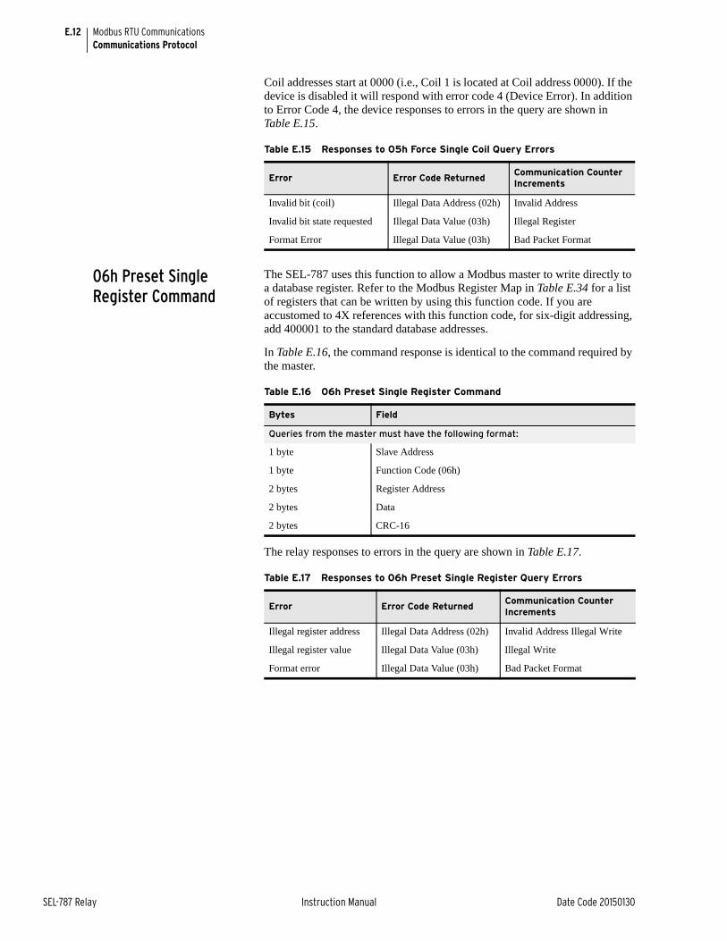
E.12
SEL-787 Relay Instruction Manual Date Code 20150130
Modbus RTU CommunicationsCommunications Protocol
Coil addresses start at 0000 (i.e., Coil 1 is located at Coil address 0000). If the device is disabled it will respond with error code 4 (Device Error). In addition to Error Code 4, the device responses to errors in the query are shown in Table E.15.
06h Preset Single Register Command
The SEL-787 uses this function to allow a Modbus master to write directly to a database register. Refer to the Modbus Register Map in Table E.34 for a list of registers that can be written by using this function code. If you are accustomed to 4X references with this function code, for six-digit addressing, add 400001 to the standard database addresses.
In Table E.16, the command response is identical to the command required by the master.
The relay responses to errors in the query are shown in Table E.17.
Table E.15 Responses to 05h Force Single Coil Query Errors
Error Error Code ReturnedCommunication Counter Increments
Invalid bit (coil) Illegal Data Address (02h) Invalid Address
Invalid bit state requested Illegal Data Value (03h) Illegal Register
Format Error Illegal Data Value (03h) Bad Packet Format
Table E.16 06h Preset Single Register Command
Bytes Field
Queries from the master must have the following format:
1 byte Slave Address
1 byte Function Code (06h)
2 bytes Register Address
2 bytes Data
2 bytes CRC-16
Table E.17 Responses to 06h Preset Single Register Query Errors
Error Error Code ReturnedCommunication Counter Increments
Illegal register address Illegal Data Address (02h) Invalid Address Illegal Write
Illegal register value Illegal Data Value (03h) Illegal Write
Format error Illegal Data Value (03h) Bad Packet Format

E.13
Date Code 20150130 Instruction Manual SEL-787 Relay
Modbus RTU CommunicationsCommunications Protocol
08h Loopback Diagnostic Command
The SEL-787 uses this function to allow a Modbus master to perform a diagnostic test on the Modbus communications channel and relay. When the subfunction field is 0000h, the relay returns a replica of the received message.
The relay responses to errors in the query are shown in Table E.19.
10h Preset Multiple Registers Command
This function code works much like code 06h, except that it allows you to write multiple registers at once, as many as 100 per operation. If you are accustomed to 4X references with the function code, for six-digit addressing, simply add 400001 to the standard database addresses.
Table E.18 08h Loopback Diagnostic Command
Bytes Field
Requests from the master must have the following format:
1 byte Slave Address
1 byte Function Code (08h)
2 bytes Subfunction (0000h)
2 bytes Data Field
2 bytes CRC-16
A successful response from the slave will have the following format:
1 byte Slave Address
1 byte Function Code (08h)
2 bytes Subfunction (0000h)
2 bytes Data Field (identical to data in Master request)
2 bytes CRC-16
Table E.19 Responses to 08h Loopback Diagnostic Query Errors
Error Error Code ReturnedCommunication Counter Increments
Illegal subfunction code Illegal Data Value (03h) Invalid Function Code/Op Code
Format error Illegal Data Value (03h) Bad Packet Format
Table E.20 10h Preset Multiple Registers Command (Sheet 1 of 2)
Bytes Field
Queries from the master must have the following format:
1 byte Slave Address
1 byte Function Code (10h)
2 bytes Starting Address
2 bytes Number of Registers to Write
1 byte Number of Bytes of Data (n)
n bytes Data
2 bytes CRC-16
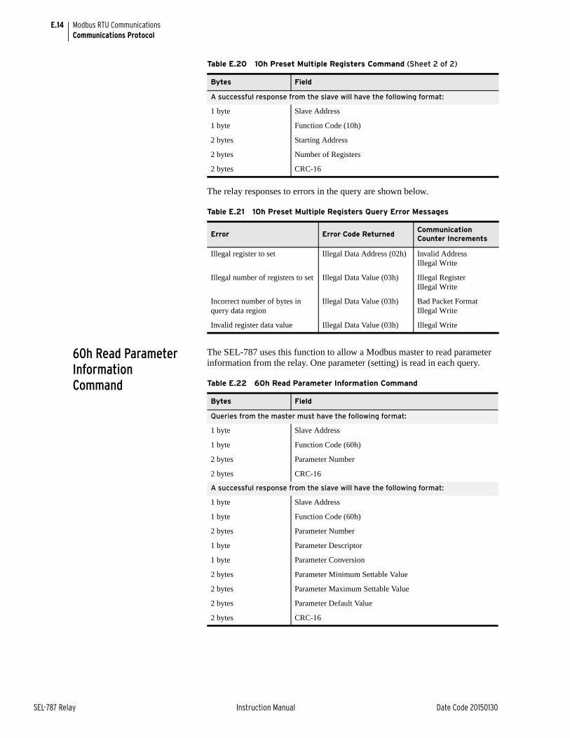
E.14
SEL-787 Relay Instruction Manual Date Code 20150130
Modbus RTU CommunicationsCommunications Protocol
The relay responses to errors in the query are shown below.
60h Read Parameter Information Command
The SEL-787 uses this function to allow a Modbus master to read parameter information from the relay. One parameter (setting) is read in each query.
A successful response from the slave will have the following format:
1 byte Slave Address
1 byte Function Code (10h)
2 bytes Starting Address
2 bytes Number of Registers
2 bytes CRC-16
Table E.21 10h Preset Multiple Registers Query Error Messages
Error Error Code ReturnedCommunication Counter Increments
Illegal register to set Illegal Data Address (02h) Invalid Address Illegal Write
Illegal number of registers to set Illegal Data Value (03h) Illegal Register Illegal Write
Incorrect number of bytes in query data region
Illegal Data Value (03h) Bad Packet Format Illegal Write
Invalid register data value Illegal Data Value (03h) Illegal Write
Table E.20 10h Preset Multiple Registers Command (Sheet 2 of 2)
Bytes Field
Table E.22 60h Read Parameter Information Command
Bytes Field
Queries from the master must have the following format:
1 byte Slave Address
1 byte Function Code (60h)
2 bytes Parameter Number
2 bytes CRC-16
A successful response from the slave will have the following format:
1 byte Slave Address
1 byte Function Code (60h)
2 bytes Parameter Number
1 byte Parameter Descriptor
1 byte Parameter Conversion
2 bytes Parameter Minimum Settable Value
2 bytes Parameter Maximum Settable Value
2 bytes Parameter Default Value
2 bytes CRC-16
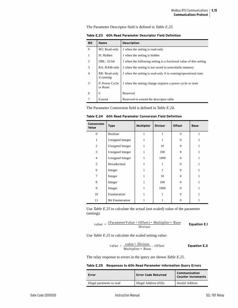
E.15
Date Code 20150130 Instruction Manual SEL-787 Relay
Modbus RTU CommunicationsCommunications Protocol
The Parameter Descriptor field is defined in Table E.23.
The Parameter Conversion field is defined in Table E.24.
Use Table E.25 to calculate the actual (not scaled) value of the parameter (setting):
Equation E.1
Use Table E.25 to calculate the scaled setting value:
Equation E.2
The relay response to errors in the query are shown Table E.25.
Table E.23 60h Read Parameter Descriptor Field Definition
Bit Name Description
0 RO: Read-only 1 when the setting is read-only
1 H: Hidden 1 when the setting is hidden
2 DBL: 32-bit 1 when the following setting is a fractional value of this setting
3 RA: RAM-only 1 when the setting is not saved in nonvolatile memory
4 RR: Read-only if running
1 when the setting is read-only if in running/operational state
5‘ P: Power Cycle or Reset
1 when the setting change requires a power cycle or reset
6 0 Reserved
7 Extend Reserved to extend the descriptor table
Table E.24 60h Read Parameter Conversion Field Definition
Conversion Value
Type Multiplier Divisor Offset Base
0 Boolean 1 1 0 1
1 Unsigned Integer 1 1 0 1
2 Unsigned Integer 1 10 0 1
3 Unsigned Integer 1 100 0 1
4 Unsigned Integer 1 1000 0 1
5 Hexadecimal 1 1 0 1
6 Integer 1 1 0 1
7 Integer 1 10 0 1
8 Integer 1 100 0 1
9 Integer 1 1000 0 1
10 Enumeration 1 1 0 1
11 Bit Enumeration 1 1 0 1
Table E.25 Responses to 60h Read Parameter Information Query Errors
Error Error Code ReturnedCommunication Counter Increments
Illegal parameter to read Illegal Address (02h) Invalid Address
value ParameterValue Offset+ Multiplier Base• • Divisor
----------------------------------------------------------------------------------------------------------------------------=
value value Divisor• Multiplier Base• ---------------------------------------------- Offset–=
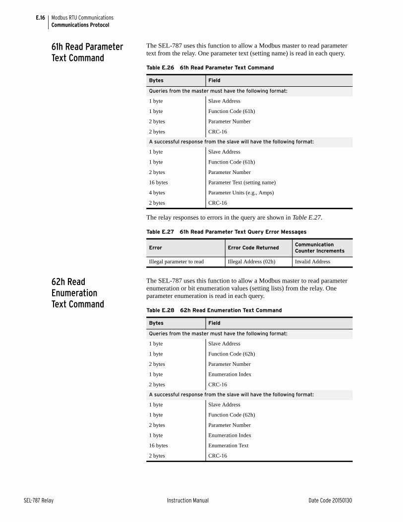
E.16
SEL-787 Relay Instruction Manual Date Code 20150130
Modbus RTU CommunicationsCommunications Protocol
61h Read Parameter Text Command
The SEL-787 uses this function to allow a Modbus master to read parameter text from the relay. One parameter text (setting name) is read in each query.
The relay responses to errors in the query are shown in Table E.27.
62h Read Enumeration Text Command
The SEL-787 uses this function to allow a Modbus master to read parameter enumeration or bit enumeration values (setting lists) from the relay. One parameter enumeration is read in each query.
Table E.26 61h Read Parameter Text Command
Bytes Field
Queries from the master must have the following format:
1 byte Slave Address
1 byte Function Code (61h)
2 bytes Parameter Number
2 bytes CRC-16
A successful response from the slave will have the following format:
1 byte Slave Address
1 byte Function Code (61h)
2 bytes Parameter Number
16 bytes Parameter Text (setting name)
4 bytes Parameter Units (e.g., Amps)
2 bytes CRC-16
Table E.27 61h Read Parameter Text Query Error Messages
Error Error Code ReturnedCommunication Counter Increments
Illegal parameter to read Illegal Address (02h) Invalid Address
Table E.28 62h Read Enumeration Text Command
Bytes Field
Queries from the master must have the following format:
1 byte Slave Address
1 byte Function Code (62h)
2 bytes Parameter Number
1 byte Enumeration Index
2 bytes CRC-16
A successful response from the slave will have the following format:
1 byte Slave Address
1 byte Function Code (62h)
2 bytes Parameter Number
1 byte Enumeration Index
16 bytes Enumeration Text
2 bytes CRC-16
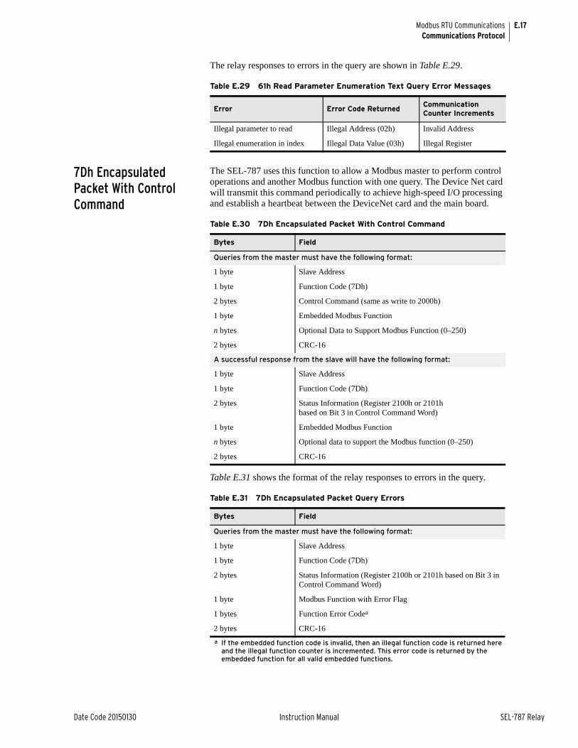
E.17
Date Code 20150130 Instruction Manual SEL-787 Relay
Modbus RTU CommunicationsCommunications Protocol
The relay responses to errors in the query are shown in Table E.29.
7Dh Encapsulated Packet With Control Command
The SEL-787 uses this function to allow a Modbus master to perform control operations and another Modbus function with one query. The Device Net card will transmit this command periodically to achieve high-speed I/O processing and establish a heartbeat between the DeviceNet card and the main board.
Table E.31 shows the format of the relay responses to errors in the query.
Table E.29 61h Read Parameter Enumeration Text Query Error Messages
Error Error Code ReturnedCommunication Counter Increments
Illegal parameter to read Illegal Address (02h) Invalid Address
Illegal enumeration in index Illegal Data Value (03h) Illegal Register
Table E.30 7Dh Encapsulated Packet With Control Command
Bytes Field
Queries from the master must have the following format:
1 byte Slave Address
1 byte Function Code (7Dh)
2 bytes Control Command (same as write to 2000h)
1 byte Embedded Modbus Function
n bytes Optional Data to Support Modbus Function (0–250)
2 bytes CRC-16
A successful response from the slave will have the following format:
1 byte Slave Address
1 byte Function Code (7Dh)
2 bytes Status Information (Register 2100h or 2101h based on Bit 3 in Control Command Word)
1 byte Embedded Modbus Function
n bytes Optional data to support the Modbus function (0–250)
2 bytes CRC-16
Table E.31 7Dh Encapsulated Packet Query Errors
Bytes Field
Queries from the master must have the following format:
1 byte Slave Address
1 byte Function Code (7Dh)
2 bytes Status Information (Register 2100h or 2101h based on Bit 3 in Control Command Word)
1 byte Modbus Function with Error Flag
1 bytes Function Error Codea
a If the embedded function code is invalid, then an illegal function code is returned here and the illegal function counter is incremented. This error code is returned by the embedded function for all valid embedded functions.
2 bytes CRC-16
E.18
SEL-787 Relay Instruction Manual Date Code 20150130
Modbus RTU CommunicationsCommunications Protocol
7Eh NOP Command This function code has no operation. This allows a Modbus master to perform a control operation without any other Modbus command. This is only used inside of the 7Dh when no regular Modbus query is required.
Reading Parameter Information and Value Using Modbus
Through use of Modbus commands, you can read the present value of a parameter as well as parameter name, units, low limit, high limit, scale, and even the enumeration string (if the parameter is an enumeration type). This means that you can use a general user interface to retrieve and display specific parameter details from the relay. Use the 60h, 61h, and 62h commands to retrieve parameter information, and use the 03 command to retrieve values.
Modifying Relay Settings Using Modbus
The SEL-787 does not provide password protection. It is assumed that because the interface is a binary protocol with CRC-16 protection, the interface is being handled by an intelligent master system. Therefore, the master would provide password protection.
Any of the settings listed in the Modbus Register Map (Table E.34) can be changed. The high and low limits provided in the table might cover a wider range than what is acceptable by the particular model or configuration. The settings are not saved as and when they are received. The relay acknowledges the write operation, but it does not change the relay settings. The relay holds these settings until there are no further edits for a time specified by SETTINGS TIMEOUT register (4010h). After this timeout, the relay attempts to save the settings. If there are no errors, the settings are saved. If, however, a setting interdependency rule is violated, the settings are not saved. The relay will set the Config Fault bit in the TRIP STATUS HI register to indicate that the save settings operation has failed. The relay will also set ERROR REGISTER (4016h) flags to indicate the type of error and ERROR ADDRESS Register to indicate the register that caused the issue.
Parameters such as date and time can be changed with the appropriate registers by using Modbus Function Code 06h or 10h.
The ability to change the settings via Modbus protocol can be blocked by the Global Setting BLKMBSET or the BLOCK MODBUS SET register.
Controlling Output Contacts Using Modbus
The SEL-787 includes registers for controlling some of the outputs. See LOGIC COMMAND (2000h), RESET COMMAND (2001h), and registers in the Reset Settings region for the control features supported by the relay. Use Modbus function codes 06h or 10h to write appropriate flags. Remember that when writing to the Logic command register with output contacts, it is not a bit operation. All the bits in that register need to be written together to reflect the state you want for each of the outputs.
Table E.32 7Eh NOP Command
Bytes Field
An example of a 7D message response using 7E will have the following format:
1 byte Slave Address
1 byte Function Code (7Dh)
2 bytes Status Information
1 byte Function Code (7Eh)
2 bytes CRC-16
E.19
Date Code 20150130 Instruction Manual SEL-787 Relay
Modbus RTU CommunicationsCommunications Protocol
User-Defined Modbus Data Region and SET M Command
The SEL-787 Modbus Register Map defines an area of 125 contiguous addresses whose contents are defined by 125 user-settable addresses. This feature allows you to take 125 discrete values from anywhere in the Modbus Register Map and place them in contiguous registers that you can then read in a single command. SEL ASCII command SET M provides a convenient method to define the user map addresses. The user map can also be defined by writing to user map registers MOD_001 to MOD_125.
To use the user-defined data region, follow the steps listed below.
Step 1. Define the list of desired quantities (as many as 125). Arrange the quantities in any order that is convenient for you to use.
Step 2. Refer to Table E.33 for a list of the Modbus label for each quantity.
Step 3. Execute SET M command from the command line to map user registers 001 to 125 (MOD_001 to MOD_125) using the labels in Table E.33.
Note that this step can also be performed using Modbus protocol. Use Modbus Function Code 06h to write to registers MOD_001 through MOD_125.
Step 4. Use Modbus function code 03h or 04h to read the desired quantities from addresses 126 through 250 (user map values).
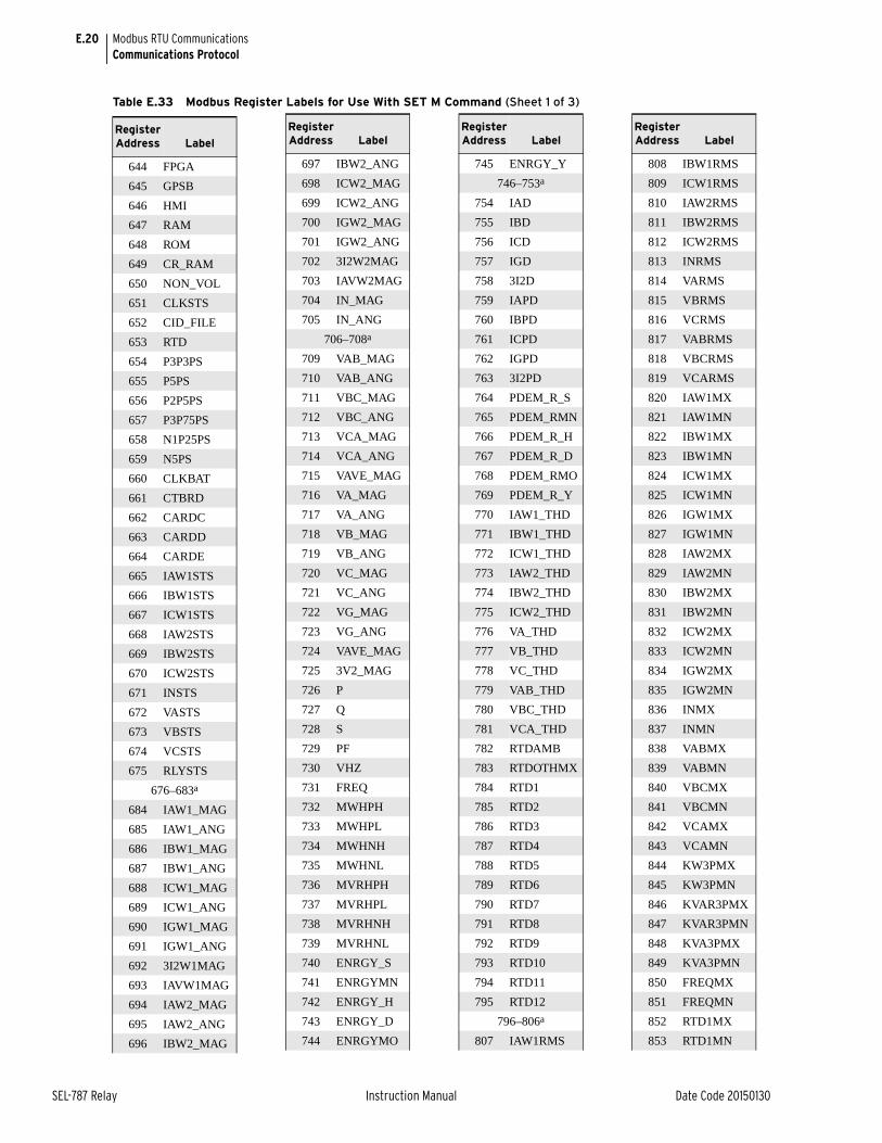
E.20
SEL-787 Relay Instruction Manual Date Code 20150130
Modbus RTU CommunicationsCommunications Protocol
Instruction Manual
Table E.33 Modbus Register Labels for Use With SET M Command (Sheet 1 of 3)
Register Address Label
644 FPGA
645 GPSB
646 HMI
647 RAM
648 ROM
649 CR_RAM
650 NON_VOL
651 CLKSTS
652 CID_FILE
653 RTD
654 P3P3PS
655 P5PS
656 P2P5PS
657 P3P75PS
658 N1P25PS
659 N5PS
660 CLKBAT
661 CTBRD
662 CARDC
663 CARDD
664 CARDE
665 IAW1STS
666 IBW1STS
667 ICW1STS
668 IAW2STS
669 IBW2STS
670 ICW2STS
671 INSTS
672 VASTS
673 VBSTS
674 VCSTS
675 RLYSTS
676–683a
684 IAW1_MAG
685 IAW1_ANG
686 IBW1_MAG
687 IBW1_ANG
688 ICW1_MAG
689 ICW1_ANG
690 IGW1_MAG
691 IGW1_ANG
692 3I2W1MAG
693 IAVW1MAG
694 IAW2_MAG
695 IAW2_ANG
696 IBW2_MAG
697 IBW2_ANG
698 ICW2_MAG
699 ICW2_ANG
700 IGW2_MAG
701 IGW2_ANG
702 3I2W2MAG
703 IAVW2MAG
704 IN_MAG
705 IN_ANG
706–708a
709 VAB_MAG
710 VAB_ANG
711 VBC_MAG
712 VBC_ANG
713 VCA_MAG
714 VCA_ANG
715 VAVE_MAG
716 VA_MAG
717 VA_ANG
718 VB_MAG
719 VB_ANG
720 VC_MAG
721 VC_ANG
722 VG_MAG
723 VG_ANG
724 VAVE_MAG
725 3V2_MAG
726 P
727 Q
728 S
729 PF
730 VHZ
731 FREQ
732 MWHPH
733 MWHPL
734 MWHNH
735 MWHNL
736 MVRHPH
737 MVRHPL
738 MVRHNH
739 MVRHNL
740 ENRGY_S
741 ENRGYMN
742 ENRGY_H
743 ENRGY_D
744 ENRGYMO
Register Address Label
745 ENRGY_Y
746–753a
754 IAD
755 IBD
756 ICD
757 IGD
758 3I2D
759 IAPD
760 IBPD
761 ICPD
762 IGPD
763 3I2PD
764 PDEM_R_S
765 PDEM_RMN
766 PDEM_R_H
767 PDEM_R_D
768 PDEM_RMO
769 PDEM_R_Y
770 IAW1_THD
771 IBW1_THD
772 ICW1_THD
773 IAW2_THD
774 IBW2_THD
775 ICW2_THD
776 VA_THD
777 VB_THD
778 VC_THD
779 VAB_THD
780 VBC_THD
781 VCA_THD
782 RTDAMB
783 RTDOTHMX
784 RTD1
785 RTD2
786 RTD3
787 RTD4
788 RTD5
789 RTD6
790 RTD7
791 RTD8
792 RTD9
793 RTD10
794 RTD11
795 RTD12
796–806a
807 IAW1RMS
Register Address Label
808 IBW1RMS
809 ICW1RMS
810 IAW2RMS
811 IBW2RMS
812 ICW2RMS
813 INRMS
814 VARMS
815 VBRMS
816 VCRMS
817 VABRMS
818 VBCRMS
819 VCARMS
820 IAW1MX
821 IAW1MN
822 IBW1MX
823 IBW1MN
824 ICW1MX
825 ICW1MN
826 IGW1MX
827 IGW1MN
828 IAW2MX
829 IAW2MN
830 IBW2MX
831 IBW2MN
832 ICW2MX
833 ICW2MN
834 IGW2MX
835 IGW2MN
836 INMX
837 INMN
838 VABMX
839 VABMN
840 VBCMX
841 VBCMN
842 VCAMX
843 VCAMN
844 KW3PMX
845 KW3PMN
846 KVAR3PMX
847 KVAR3PMN
848 KVA3PMX
849 KVA3PMN
850 FREQMX
851 FREQMN
852 RTD1MX
853 RTD1MN
Register Address Label

E.21
Date Code 20150130 Instruction Manual SEL-787 Relay
Modbus RTU CommunicationsCommunications Protocol
Instruction Manual
Table E.33 Modbus Register Labels for Use With SET M Command (Sheet 2 of 3)
854 RTD2MX
855 RTD2MN
856 RTD3MX
857 RTD3MN
858 RTD4MX
859 RTD4MN
860 RTD5MX
861 RTD5MN
862 RTD6MX
863 RTD6MN
864 RTD7MX
865 RTD7MN
866 RTD8MX
867 RTD8MN
868 RTD9MX
869 RTD9MN
870 RTD10MX
871 RTD10MN
872 RTD11MX
873 RTD11MN
874 RTD12MX
875 RTD12MN
876 AI301MXH
877 AI301MXL
878 AI301MNH
879 AI301MNL
880 AI302MXH
881 AI302MXL
882 AI302MNH
883 AI302MNL
884 AI303MXH
885 AI303MXL
886 AI303MNH
887 AI303MNL
888 AI304MXH
889 AI304MXL
890 AI304MNH
891 AI304MNL
892 AI401MXH
893 AI401MXL
894 AI401MNH
895 AI401MNL
896 AI402MXH
897 AI402MXL
898 AI402MNH
899 AI402MNL
Register Address Label
900 AI403MXH
901 AI403MXL
902 AI403MNH
903 AI403MNL
904 AI403MXH
905 AI403MXL
906 AI404MNH
907 AI404MNL
908 AI501MXH
909 AI501MXL
910 AI501MNH
911 AI501MNL
912 AI502MXH
913 AI502MXL
914 AI502MNH
915 AI502MNL
916 AI503MXH
917 AI503MXL
918 AI503MNH
919 AI503MNL
920 AI504MXH
921 AI504MXL
922 AI504MNH
923 AI504MNL
924 MXMN_R_S
925 MXMN_RMN
926 MXMN_R_H
927 MXMN_R_D
928 MXMN_RMO
929 MXMN_R_Y
930–939a
940 AI301H
941 AI301L
942 AI302H
943 AI302L
944 AI303H
945 AI303L
946 AI304H
947 AI304L
948 AI401H
949 AI401L
950 AI402H
951 AI402L
952 AI403H
953 AI403L
954 AI404H
Register Address Label
955 AI404L
956 AI501H
957 AI501L
958 AI502H
959 AI502L
960 AI503H
961 AI503L
962 AI504H
963 AI504L
964–969a
970 MV01H
971 MV01L
972 MV02H
973 MV02L
974 MV03H
975 MV03L
976 MV04H
977 MV04L
978 MV05H
979 MV05L
980 MV06H
981 MV06L
982 MV07H
983 MV07L
984 MV08H
985 MV08L
986 MV09H
987 MV09L
988 MV10H
989 MV10L
990 MV11H
991 MV11L
992 MV12H
993 MV12L
994 MV13H
995 MV13L
996 MV14H
997 MV14L
998 MV15H
999 MV15L
1000 MV16H
1001 MV16L
1002 MV17H
1003 MV17L
1004 MV18H
1005 MV18L
Register Address Label
1006 MV19H
1007 MV19L
1008 MV20H
1009 MV20L
1010 MV21H
1011 MV21L
1012 MV22H
1013 MV22L
1014 MV23H
1015 MV23L
1016 MV24H
1017 MV24L
1018 MV25H
1019 MV25L
1020 MV26H
1021 MV26L
1022 MV27H
1023 MV27L
1024 MV28H
1025 MV28L
1026 MV29H
1027 MV29L
1028 MV30H
1029 MV30L
1030 MV31H
1031 MV31L
1032 MV32H
1033 MV32L
1034 SC01
1035 SC02
1036 SC03
1037 SC04
1038 SC05
1039 SC06
1040 SC07
1041 SC08
1042 SC09
1043 SC10
1044 SC11
1045 SC12
1046 SC13
1047 SC14
1048 SC15
1049 SC16
1050 SC17
1051 SC18
Register Address Label
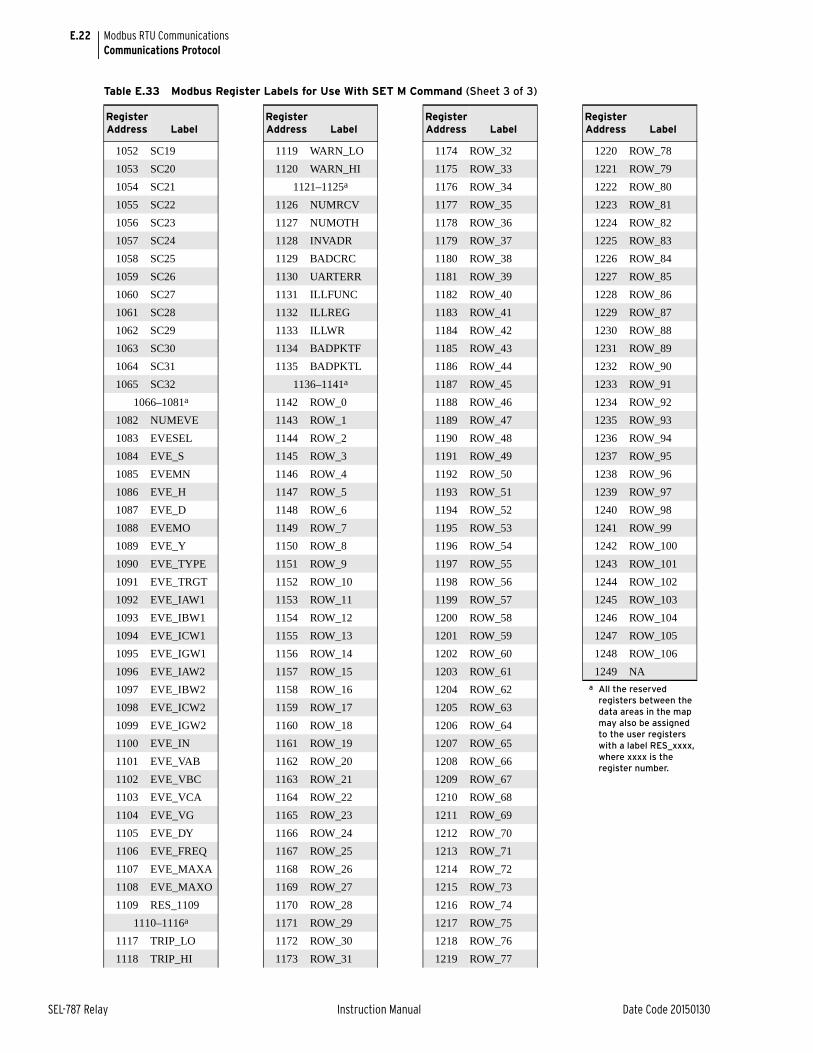
E.22
SEL-787 Relay Instruction Manual Date Code 20150130
Modbus RTU CommunicationsCommunications Protocol
Table E.33 Modbus Register Labels for Use With SET M Command (Sheet 3 of 3)
1052 SC19
1053 SC20
1054 SC21
1055 SC22
1056 SC23
1057 SC24
1058 SC25
1059 SC26
1060 SC27
1061 SC28
1062 SC29
1063 SC30
1064 SC31
1065 SC32
1066–1081a
1082 NUMEVE
1083 EVESEL
1084 EVE_S
1085 EVEMN
1086 EVE_H
1087 EVE_D
1088 EVEMO
1089 EVE_Y
1090 EVE_TYPE
1091 EVE_TRGT
1092 EVE_IAW1
1093 EVE_IBW1
1094 EVE_ICW1
1095 EVE_IGW1
1096 EVE_IAW2
1097 EVE_IBW2
1098 EVE_ICW2
1099 EVE_IGW2
1100 EVE_IN
1101 EVE_VAB
1102 EVE_VBC
1103 EVE_VCA
1104 EVE_VG
1105 EVE_DY
1106 EVE_FREQ
1107 EVE_MAXA
1108 EVE_MAXO
1109 RES_1109
1110–1116a
1117 TRIP_LO
1118 TRIP_HI
Register Address Label
1119 WARN_LO
1120 WARN_HI
1121–1125a
1126 NUMRCV
1127 NUMOTH
1128 INVADR
1129 BADCRC
1130 UARTERR
1131 ILLFUNC
1132 ILLREG
1133 ILLWR
1134 BADPKTF
1135 BADPKTL
1136–1141a
1142 ROW_0
1143 ROW_1
1144 ROW_2
1145 ROW_3
1146 ROW_4
1147 ROW_5
1148 ROW_6
1149 ROW_7
1150 ROW_8
1151 ROW_9
1152 ROW_10
1153 ROW_11
1154 ROW_12
1155 ROW_13
1156 ROW_14
1157 ROW_15
1158 ROW_16
1159 ROW_17
1160 ROW_18
1161 ROW_19
1162 ROW_20
1163 ROW_21
1164 ROW_22
1165 ROW_23
1166 ROW_24
1167 ROW_25
1168 ROW_26
1169 ROW_27
1170 ROW_28
1171 ROW_29
1172 ROW_30
1173 ROW_31
Register Address Label
1174 ROW_32
1175 ROW_33
1176 ROW_34
1177 ROW_35
1178 ROW_36
1179 ROW_37
1180 ROW_38
1181 ROW_39
1182 ROW_40
1183 ROW_41
1184 ROW_42
1185 ROW_43
1186 ROW_44
1187 ROW_45
1188 ROW_46
1189 ROW_47
1190 ROW_48
1191 ROW_49
1192 ROW_50
1193 ROW_51
1194 ROW_52
1195 ROW_53
1196 ROW_54
1197 ROW_55
1198 ROW_56
1199 ROW_57
1200 ROW_58
1201 ROW_59
1202 ROW_60
1203 ROW_61
1204 ROW_62
1205 ROW_63
1206 ROW_64
1207 ROW_65
1208 ROW_66
1209 ROW_67
1210 ROW_68
1211 ROW_69
1212 ROW_70
1213 ROW_71
1214 ROW_72
1215 ROW_73
1216 ROW_74
1217 ROW_75
1218 ROW_76
1219 ROW_77
Register Address Label
1220 ROW_78
1221 ROW_79
1222 ROW_80
1223 ROW_81
1224 ROW_82
1225 ROW_83
1226 ROW_84
1227 ROW_85
1228 ROW_86
1229 ROW_87
1230 ROW_88
1231 ROW_89
1232 ROW_90
1233 ROW_91
1234 ROW_92
1235 ROW_93
1236 ROW_94
1237 ROW_95
1238 ROW_96
1239 ROW_97
1240 ROW_98
1241 ROW_99
1242 ROW_100
1243 ROW_101
1244 ROW_102
1245 ROW_103
1246 ROW_104
1247 ROW_105
1248 ROW_106
1249 NAa All the reserved
registers between the data areas in the map may also be assigned to the user registers with a label RES_xxxx, where xxxx is the register number.
Register Address Label
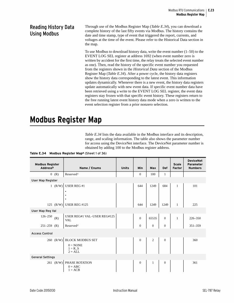
E.23
Date Code 20150130 Instruction Manual SEL-787 Relay
Modbus RTU CommunicationsModbus Register Map
Reading History Data Using Modbus
Through use of the Modbus Register Map (Table E.34), you can download a complete history of the last fifty events via Modbus. The history contains the date and time stamp, type of event that triggered the report, currents, and voltages at the time of the event. Please refer to the Historical Data section in the map.
To use Modbus to download history data, write the event number (1–50) to the EVENT LOG SEL register at address 1692 (when event number zero is written by accident for the first time, the relay treats the selected event number as one). Then, read the history of the specific event number you requested from the registers shown in the Historical Data section of the Modbus Register Map (Table E.34). After a power cycle, the history data registers show the history data corresponding to the latest event. This information updates dynamically. Whenever there is a new event, the history data registers update automatically with new event data. If specific event number data have been retrieved using a write to the EVENT LOG SEL register, the event data registers stay frozen with that specific event history. These registers return to the free running latest event history data mode when a zero is written to the event selection register from a prior nonzero selection. Instruction Manual
Modbus Register Map
Table E.34 lists the data available in the Modbus interface and its description, range, and scaling information. The table also shows the parameter number for access using the DeviceNet interface. The DeviceNet parameter number is obtained by adding 100 to the Modbus register address.
Table E.34 Modbus Register Mapa (Sheet 1 of 36)
Modbus Register Addressb Name / Enums Units Min Max Def
Scale Factor
DeviceNet Parameter Numbers
0 (R) Reservedc 0 100 1
User Map Register
1 (R/W) USER REG #1 644 1249 684 1 101
•••
125 (R/W) USER REG #125 644 1249 1249 1 225
User Map Reg Val
126–250(R)
USER REG#1 VAL–USER REG#125 VAL
0 65535 0 1 226–350
251–259 (R) Reservedc 0 0 0 351–359
Access Control
260 (R/W) BLOCK MODBUS SET 0 2 0 360
0 = NONE1 = R_S2 = ALL
General Settings
261 (R/W) PHASE ROTATION 0 1 0 3610 = ABC1 = ACB
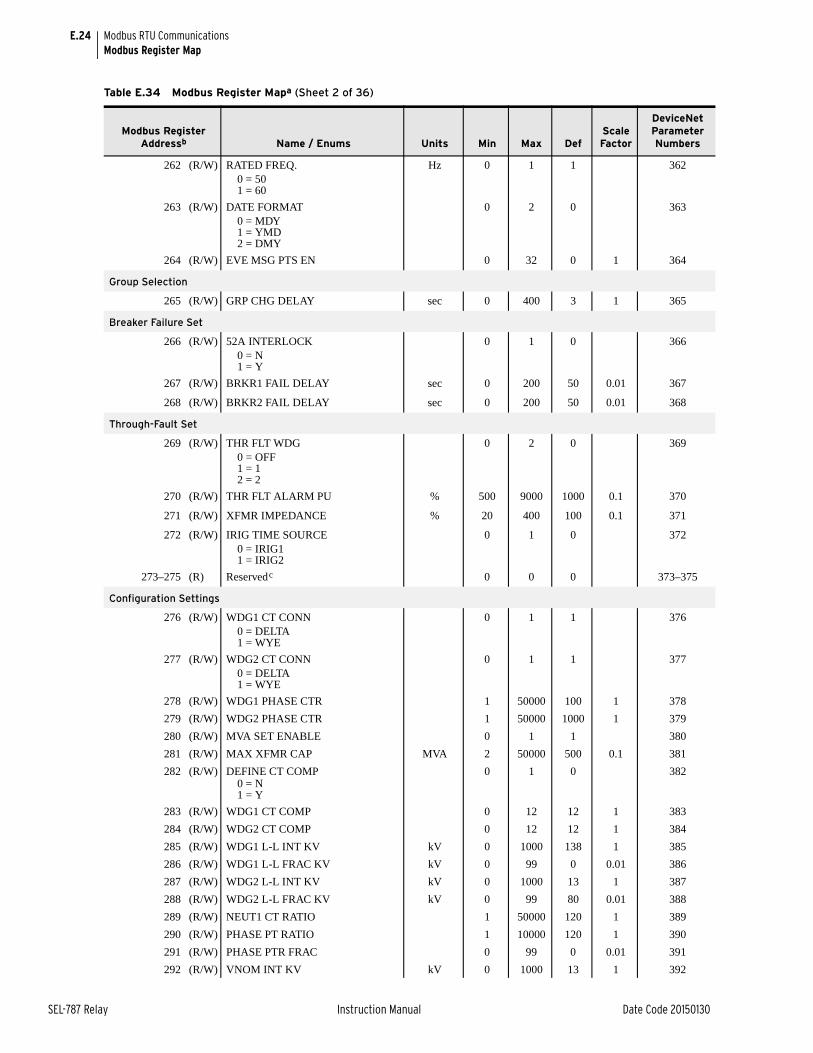
E.24
SEL-787 Relay Instruction Manual Date Code 20150130
Modbus RTU CommunicationsModbus Register Map
262 (R/W) RATED FREQ. Hz 0 1 1 3620 = 501 = 60
263 (R/W) DATE FORMAT 0 2 0 3630 = MDY1 = YMD2 = DMY
264 (R/W) EVE MSG PTS EN 0 32 0 1 364
Group Selection
265 (R/W) GRP CHG DELAY sec 0 400 3 1 365
Breaker Failure Set
266 (R/W) 52A INTERLOCK 0 1 0 3660 = N1 = Y
267 (R/W) BRKR1 FAIL DELAY sec 0 200 50 0.01 367
268 (R/W) BRKR2 FAIL DELAY sec 0 200 50 0.01 368
Through-Fault Set
269 (R/W) THR FLT WDG 0 2 0 3690 = OFF1 = 12 = 2
270 (R/W) THR FLT ALARM PU % 500 9000 1000 0.1 370
271 (R/W) XFMR IMPEDANCE % 20 400 100 0.1 371
272 (R/W) IRIG TIME SOURCE 0 1 0 3720 = IRIG11 = IRIG2
273–275 (R) Reservedc 0 0 0 373–375
Configuration Settings
276 (R/W) WDG1 CT CONN 0 1 1 3760 = DELTA1 = WYE
277 (R/W) WDG2 CT CONN 0 1 1 3770 = DELTA1 = WYE
278 (R/W) WDG1 PHASE CTR 1 50000 100 1 378
279 (R/W) WDG2 PHASE CTR 1 50000 1000 1 379
280 (R/W) MVA SET ENABLE 0 1 1 380
281 (R/W) MAX XFMR CAP MVA 2 50000 500 0.1 381
282 (R/W) DEFINE CT COMP 0 1 0 3820 = N1 = Y
283 (R/W) WDG1 CT COMP 0 12 12 1 383
284 (R/W) WDG2 CT COMP 0 12 12 1 384
285 (R/W) WDG1 L-L INT KV kV 0 1000 138 1 385
286 (R/W) WDG1 L-L FRAC KV kV 0 99 0 0.01 386
287 (R/W) WDG2 L-L INT KV kV 0 1000 13 1 387
288 (R/W) WDG2 L-L FRAC KV kV 0 99 80 0.01 388
289 (R/W) NEUT1 CT RATIO 1 50000 120 1 389
290 (R/W) PHASE PT RATIO 1 10000 120 1 390
291 (R/W) PHASE PTR FRAC 0 99 0 0.01 391
292 (R/W) VNOM INT KV kV 0 1000 13 1 392
Table E.34 Modbus Register Mapa (Sheet 2 of 36)
Modbus Register Addressb Name / Enums Units Min Max Def
Scale Factor
DeviceNet Parameter Numbers
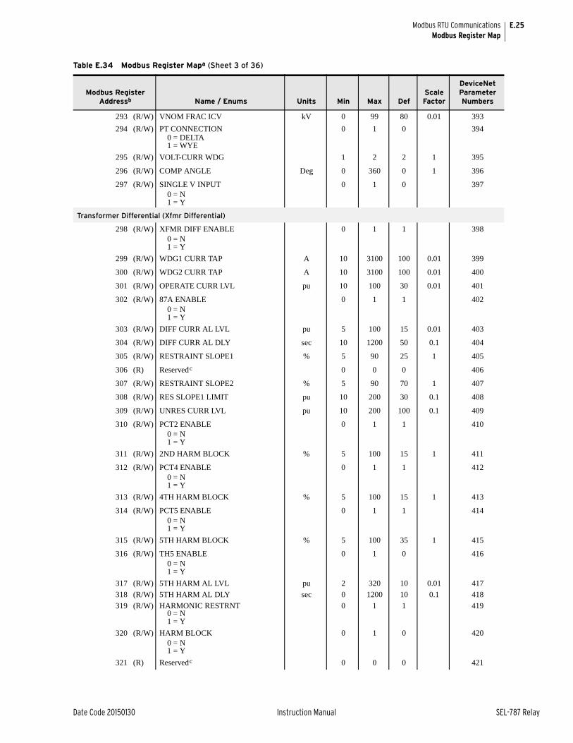
E.25
Date Code 20150130 Instruction Manual SEL-787 Relay
Modbus RTU CommunicationsModbus Register Map
293 (R/W) VNOM FRAC ICV kV 0 99 80 0.01 393
294 (R/W) PT CONNECTION 0 1 0 3940 = DELTA1 = WYE
295 (R/W) VOLT-CURR WDG 1 2 2 1 395
296 (R/W) COMP ANGLE Deg 0 360 0 1 396
297 (R/W) SINGLE V INPUT 0 1 0 3970 = N1 = Y
Transformer Differential (Xfmr Differential)
298 (R/W) XFMR DIFF ENABLE 0 1 1 3980 = N1 = Y
299 (R/W) WDG1 CURR TAP A 10 3100 100 0.01 399
300 (R/W) WDG2 CURR TAP A 10 3100 100 0.01 400
301 (R/W) OPERATE CURR LVL pu 10 100 30 0.01 401
302 (R/W) 87A ENABLE 0 1 1 4020 = N1 = Y
303 (R/W) DIFF CURR AL LVL pu 5 100 15 0.01 403
304 (R/W) DIFF CURR AL DLY sec 10 1200 50 0.1 404
305 (R/W) RESTRAINT SLOPE1 % 5 90 25 1 405
306 (R) Reservedc 0 0 0 406
307 (R/W) RESTRAINT SLOPE2 % 5 90 70 1 407
308 (R/W) RES SLOPE1 LIMIT pu 10 200 30 0.1 408
309 (R/W) UNRES CURR LVL pu 10 200 100 0.1 409
310 (R/W) PCT2 ENABLE 0 1 1 4100 = N1 = Y
311 (R/W) 2ND HARM BLOCK % 5 100 15 1 411
312 (R/W) PCT4 ENABLE 0 1 1 4120 = N1 = Y
313 (R/W) 4TH HARM BLOCK % 5 100 15 1 413
314 (R/W) PCT5 ENABLE 0 1 1 4140 = N1 = Y
315 (R/W) 5TH HARM BLOCK % 5 100 35 1 415
316 (R/W) TH5 ENABLE 0 1 0 4160 = N1 = Y
317 (R/W) 5TH HARM AL LVL pu 2 320 10 0.01 417
318 (R/W) 5TH HARM AL DLY sec 0 1200 10 0.1 418
319 (R/W) HARMONIC RESTRNT 0 1 1 4190 = N1 = Y
320 (R/W) HARM BLOCK 0 1 0 4200 = N1 = Y
321 (R) Reservedc 0 0 0 421
Table E.34 Modbus Register Mapa (Sheet 3 of 36)
Modbus Register Addressb Name / Enums Units Min Max Def
Scale Factor
DeviceNet Parameter Numbers
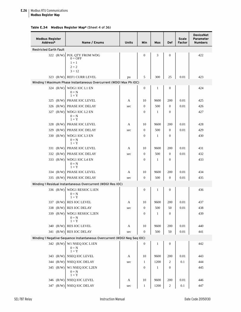
E.26
SEL-787 Relay Instruction Manual Date Code 20150130
Modbus RTU CommunicationsModbus Register Map
Restricted Earth Fault
322 (R/W) POL QTY FROM WDG 0 3 0 4220 = OFF1 = 12 = 23 = 12
323 (R/W) REF1 CURR LEVEL pu 5 300 25 0.01 423
Winding 1 Maximum Phase Instantaneous Overcurrent (WDG1 Max Ph IOC)
324 (R/W) WDG1 IOC L1 EN 0 1 0 4240 = N1 = Y
325 (R/W) PHASE IOC LEVEL A 10 9600 200 0.01 425
326 (R/W) PHASE IOC DELAY sec 0 500 0 0.01 426
327 (R/W) WDG1 IOC L2 EN 0 1 0 4270 = N1 = Y
328 (R/W) PHASE IOC LEVEL A 10 9600 200 0.01 428
329 (R/W) PHASE IOC DELAY sec 0 500 0 0.01 429
330 (R/W) WDG1 IOC L3 EN 0 1 0 4300 = N1 = Y
331 (R/W) PHASE IOC LEVEL A 10 9600 200 0.01 431
332 (R/W) PHASE IOC DELAY sec 0 500 0 0.01 432
333 (R/W) WDG1 IOC L4 EN 0 1 0 4330 = N1 = Y
334 (R/W) PHASE IOC LEVEL A 10 9600 200 0.01 434
335 (R/W) PHASE IOC DELAY sec 0 500 0 0.01 435
Winding 1 Residual Instantaneous Overcurrent (WDG1 Res IOC)
336 (R/W) WDG1 RESIOC L1EN 0 1 0 4360 = N1 = Y
337 (R/W) RES IOC LEVEL A 10 9600 200 0.01 437
338 (R/W) RES IOC DELAY sec 0 500 50 0.01 438
339 (R/W) WDG1 RESIOC L2EN 0 1 0 4390 = N1 = Y
340 (R/W) RES IOC LEVEL A 10 9600 200 0.01 440
341 (R/W) RES IOC DELAY sec 0 500 50 0.01 441
Winding 1 Negative-Sequence Instantaneous Overcurrent (WDG1 Neg Seq IOC)
342 (R/W) W1 NSEQ IOC L1EN 0 1 0 4420 = N1 = Y
343 (R/W) NSEQ IOC LEVEL A 10 9600 200 0.01 443
344 (R/W) NSEQ IOC DELAY sec 1 1200 2 0.1 444
345 (R/W) W1 NSEQ IOC L2EN 0 1 0 4450 = N1 = Y
346 (R/W) NSEQ IOC LEVEL A 10 9600 200 0.01 446
347 (R/W) NSEQ IOC DELAY sec 1 1200 2 0.1 447
Table E.34 Modbus Register Mapa (Sheet 4 of 36)
Modbus Register Addressb Name / Enums Units Min Max Def
Scale Factor
DeviceNet Parameter Numbers
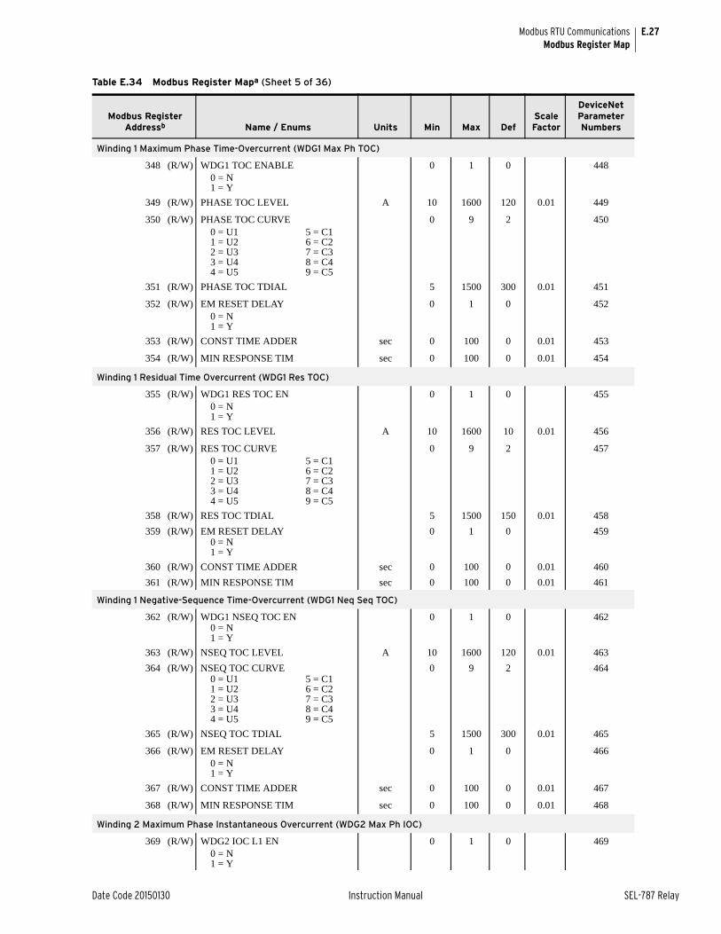
E.27
Date Code 20150130 Instruction Manual SEL-787 Relay
Modbus RTU CommunicationsModbus Register Map
Winding 1 Maximum Phase Time-Overcurrent (WDG1 Max Ph TOC)
348 (R/W) WDG1 TOC ENABLE 0 1 0 4480 = N1 = Y
349 (R/W) PHASE TOC LEVEL A 10 1600 120 0.01 449
350 (R/W) PHASE TOC CURVE 0 9 2 4500 = U1 5 = C11 = U2 6 = C22 = U3 7 = C33 = U4 8 = C44 = U5 9 = C5
351 (R/W) PHASE TOC TDIAL 5 1500 300 0.01 451
352 (R/W) EM RESET DELAY 0 1 0 4520 = N1 = Y
353 (R/W) CONST TIME ADDER sec 0 100 0 0.01 453
354 (R/W) MIN RESPONSE TIM sec 0 100 0 0.01 454
Winding 1 Residual Time Overcurrent (WDG1 Res TOC)
355 (R/W) WDG1 RES TOC EN 0 1 0 4550 = N1 = Y
356 (R/W) RES TOC LEVEL A 10 1600 10 0.01 456
357 (R/W) RES TOC CURVE 0 9 2 4570 = U1 5 = C11 = U2 6 = C22 = U3 7 = C33 = U4 8 = C44 = U5 9 = C5
358 (R/W) RES TOC TDIAL 5 1500 150 0.01 458
359 (R/W) EM RESET DELAY 0 1 0 4590 = N1 = Y
360 (R/W) CONST TIME ADDER sec 0 100 0 0.01 460
361 (R/W) MIN RESPONSE TIM sec 0 100 0 0.01 461
Winding 1 Negative-Sequence Time-Overcurrent (WDG1 Neq Seq TOC)
362 (R/W) WDG1 NSEQ TOC EN 0 1 0 4620 = N1 = Y
363 (R/W) NSEQ TOC LEVEL A 10 1600 120 0.01 463
364 (R/W) NSEQ TOC CURVE 0 9 2 4640 = U1 5 = C11 = U2 6 = C22 = U3 7 = C33 = U4 8 = C44 = U5 9 = C5
365 (R/W) NSEQ TOC TDIAL 5 1500 300 0.01 465
366 (R/W) EM RESET DELAY 0 1 0 4660 = N1 = Y
367 (R/W) CONST TIME ADDER sec 0 100 0 0.01 467
368 (R/W) MIN RESPONSE TIM sec 0 100 0 0.01 468
Winding 2 Maximum Phase Instantaneous Overcurrent (WDG2 Max Ph IOC)
369 (R/W) WDG2 IOC L1 EN 0 1 0 4690 = N1 = Y
Table E.34 Modbus Register Mapa (Sheet 5 of 36)
Modbus Register Addressb Name / Enums Units Min Max Def
Scale Factor
DeviceNet Parameter Numbers
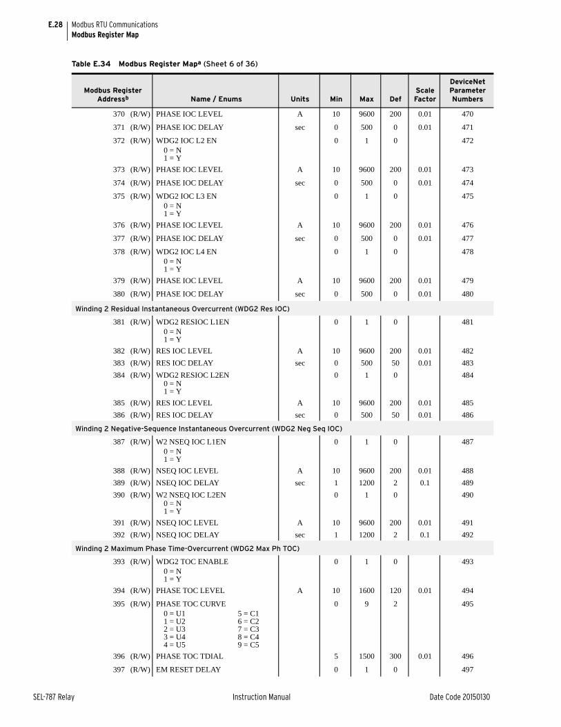
E.28
SEL-787 Relay Instruction Manual Date Code 20150130
Modbus RTU CommunicationsModbus Register Map
370 (R/W) PHASE IOC LEVEL A 10 9600 200 0.01 470
371 (R/W) PHASE IOC DELAY sec 0 500 0 0.01 471
372 (R/W) WDG2 IOC L2 EN 0 1 0 4720 = N1 = Y
373 (R/W) PHASE IOC LEVEL A 10 9600 200 0.01 473
374 (R/W) PHASE IOC DELAY sec 0 500 0 0.01 474
375 (R/W) WDG2 IOC L3 EN 0 1 0 4750 = N1 = Y
376 (R/W) PHASE IOC LEVEL A 10 9600 200 0.01 476
377 (R/W) PHASE IOC DELAY sec 0 500 0 0.01 477
378 (R/W) WDG2 IOC L4 EN 0 1 0 4780 = N1 = Y
379 (R/W) PHASE IOC LEVEL A 10 9600 200 0.01 479
380 (R/W) PHASE IOC DELAY sec 0 500 0 0.01 480
Winding 2 Residual Instantaneous Overcurrent (WDG2 Res IOC)
381 (R/W) WDG2 RESIOC L1EN 0 1 0 4810 = N1 = Y
382 (R/W) RES IOC LEVEL A 10 9600 200 0.01 482
383 (R/W) RES IOC DELAY sec 0 500 50 0.01 483
384 (R/W) WDG2 RESIOC L2EN 0 1 0 4840 = N1 = Y
385 (R/W) RES IOC LEVEL A 10 9600 200 0.01 485
386 (R/W) RES IOC DELAY sec 0 500 50 0.01 486
Winding 2 Negative-Sequence Instantaneous Overcurrent (WDG2 Neg Seq IOC)
387 (R/W) W2 NSEQ IOC L1EN 0 1 0 4870 = N1 = Y
388 (R/W) NSEQ IOC LEVEL A 10 9600 200 0.01 488
389 (R/W) NSEQ IOC DELAY sec 1 1200 2 0.1 489
390 (R/W) W2 NSEQ IOC L2EN 0 1 0 4900 = N1 = Y
391 (R/W) NSEQ IOC LEVEL A 10 9600 200 0.01 491
392 (R/W) NSEQ IOC DELAY sec 1 1200 2 0.1 492
Winding 2 Maximum Phase Time-Overcurrent (WDG2 Max Ph TOC)
393 (R/W) WDG2 TOC ENABLE 0 1 0 4930 = N1 = Y
394 (R/W) PHASE TOC LEVEL A 10 1600 120 0.01 494
395 (R/W) PHASE TOC CURVE 0 9 2 4950 = U1 5 = C11 = U2 6 = C22 = U3 7 = C33 = U4 8 = C44 = U5 9 = C5
396 (R/W) PHASE TOC TDIAL 5 1500 300 0.01 496
397 (R/W) EM RESET DELAY 0 1 0 497
Table E.34 Modbus Register Mapa (Sheet 6 of 36)
Modbus Register Addressb Name / Enums Units Min Max Def
Scale Factor
DeviceNet Parameter Numbers
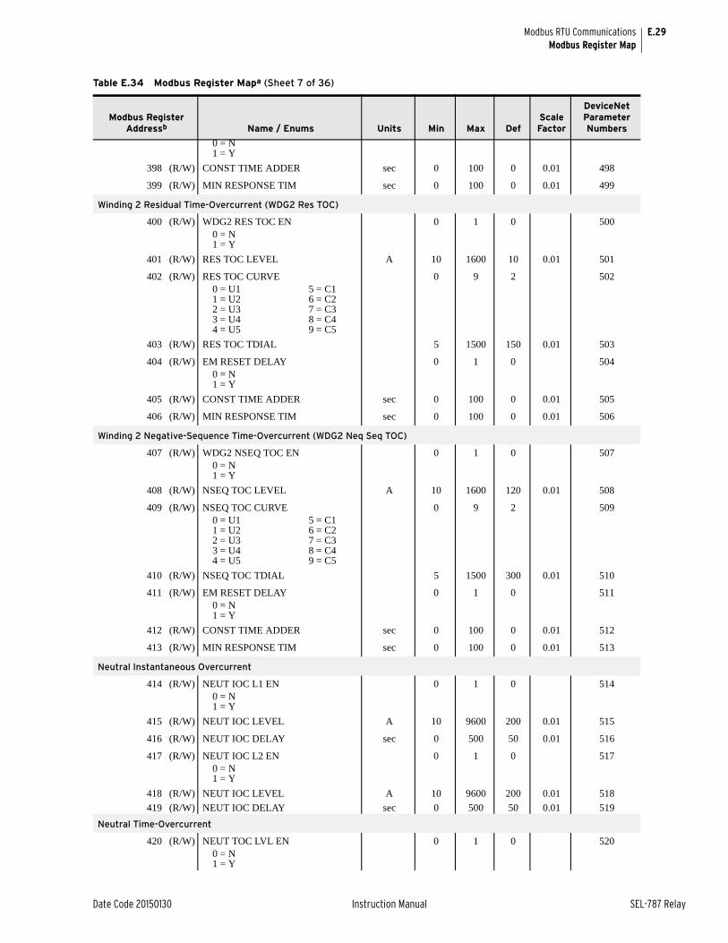
E.29
Date Code 20150130 Instruction Manual SEL-787 Relay
Modbus RTU CommunicationsModbus Register Map
0 = N1 = Y
398 (R/W) CONST TIME ADDER sec 0 100 0 0.01 498
399 (R/W) MIN RESPONSE TIM sec 0 100 0 0.01 499
Winding 2 Residual Time-Overcurrent (WDG2 Res TOC)
400 (R/W) WDG2 RES TOC EN 0 1 0 5000 = N1 = Y
401 (R/W) RES TOC LEVEL A 10 1600 10 0.01 501
402 (R/W) RES TOC CURVE 0 9 2 5020 = U1 5 = C11 = U2 6 = C22 = U3 7 = C33 = U4 8 = C44 = U5 9 = C5
403 (R/W) RES TOC TDIAL 5 1500 150 0.01 503
404 (R/W) EM RESET DELAY 0 1 0 5040 = N1 = Y
405 (R/W) CONST TIME ADDER sec 0 100 0 0.01 505
406 (R/W) MIN RESPONSE TIM sec 0 100 0 0.01 506
Winding 2 Negative-Sequence Time-Overcurrent (WDG2 Neq Seq TOC)
407 (R/W) WDG2 NSEQ TOC EN 0 1 0 5070 = N1 = Y
408 (R/W) NSEQ TOC LEVEL A 10 1600 120 0.01 508
409 (R/W) NSEQ TOC CURVE 0 9 2 5090 = U1 5 = C11 = U2 6 = C22 = U3 7 = C33 = U4 8 = C44 = U5 9 = C5
410 (R/W) NSEQ TOC TDIAL 5 1500 300 0.01 510
411 (R/W) EM RESET DELAY 0 1 0 5110 = N1 = Y
412 (R/W) CONST TIME ADDER sec 0 100 0 0.01 512
413 (R/W) MIN RESPONSE TIM sec 0 100 0 0.01 513
Neutral Instantaneous Overcurrent
414 (R/W) NEUT IOC L1 EN 0 1 0 5140 = N1 = Y
415 (R/W) NEUT IOC LEVEL A 10 9600 200 0.01 515
416 (R/W) NEUT IOC DELAY sec 0 500 50 0.01 516
417 (R/W) NEUT IOC L2 EN 0 1 0 5170 = N1 = Y
418 (R/W) NEUT IOC LEVEL A 10 9600 200 0.01 518
419 (R/W) NEUT IOC DELAY sec 0 500 50 0.01 519
Neutral Time-Overcurrent
420 (R/W) NEUT TOC LVL EN 0 1 0 5200 = N1 = Y
Table E.34 Modbus Register Mapa (Sheet 7 of 36)
Modbus Register Addressb Name / Enums Units Min Max Def
Scale Factor
DeviceNet Parameter Numbers

E.30
SEL-787 Relay Instruction Manual Date Code 20150130
Modbus RTU CommunicationsModbus Register Map
421 (R/W) NEUT TOC LEVEL A 10 1600 10 0.01 521
422 (R/W) NEUT TOC CURVE 0 9 2 5220 = U1 5 = C11 = U2 6 = C22 = U3 7 = C33 = U4 8 = C44 = U5 9 = C5
423 (R/W) NEUT TOC TDIAL 5 1500 150 0.01 523
424 (R/W) EM RESET DELAY 0 1 0 5240 = N1 = Y
425 (R/W) CONST TIME ADDER sec 0 100 0 0.01 525
426 (R/W) MIN RESPONSE TIM sec 0 100 0 0.01 526
427–431 (R) Reservedc 0 0 0 527–531
RTD Settings
432 (R/W) RTD ENABLE 0 2 0 5320 = NONE1 = INT2 = EXT
433 (R/W) RTD1 LOCATION 0 2 0 5330 = OFF1 = AMB2 = OTH
434 (R/W) RTD1 TYPE 0 3 0 5340 = PT1001 = NI1002 = NI1203 = CU10
435 (R/W) RTD1 TRIP LEVEL degC 0 250 0 1 5350 = Off
436 (R/W) RTD1 WARN LEVEL degC 0 250 0 1 5360 = Off
437 (R/W) RTD2 LOCATION 0 2 0 5370 = OFF1 = AMB2 = OTH
438 (R/W) RTD2 TYPE 0 3 0 5380 = PT1001 = NI1002 = NI1203 = CU10
439 (R/W) RTD2 TRIP LEVEL degC 0 250 0 1 5390 = Off
440 (R/W) RTD2 WARN LEVEL degC 0 250 0 1 5400 = Off
441 (R/W) RTD3 LOCATION 0 2 0 5410 = OFF1 = AMB2 = OTH
442 (R/W) RTD3 TYPE 0 3 0 5420 = PT1001 = NI1002 = NI1203 = CU10
443 (R/W) RTD3 TRIP LEVEL degC 0 250 0 1 5430 = Off
444 (R/W) RTD3 WARN LEVEL degC 0 250 0 1 544
Table E.34 Modbus Register Mapa (Sheet 8 of 36)
Modbus Register Addressb Name / Enums Units Min Max Def
Scale Factor
DeviceNet Parameter Numbers
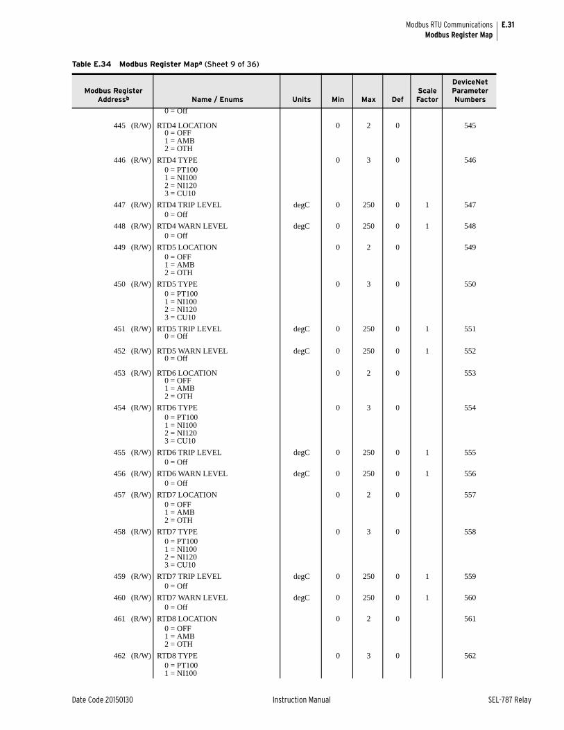
E.31
Date Code 20150130 Instruction Manual SEL-787 Relay
Modbus RTU CommunicationsModbus Register Map
0 = Off
445 (R/W) RTD4 LOCATION 0 2 0 5450 = OFF1 = AMB2 = OTH
446 (R/W) RTD4 TYPE 0 3 0 5460 = PT1001 = NI1002 = NI1203 = CU10
447 (R/W) RTD4 TRIP LEVEL degC 0 250 0 1 5470 = Off
448 (R/W) RTD4 WARN LEVEL degC 0 250 0 1 5480 = Off
449 (R/W) RTD5 LOCATION 0 2 0 5490 = OFF1 = AMB2 = OTH
450 (R/W) RTD5 TYPE 0 3 0 5500 = PT1001 = NI1002 = NI1203 = CU10
451 (R/W) RTD5 TRIP LEVEL degC 0 250 0 1 5510 = Off
452 (R/W) RTD5 WARN LEVEL degC 0 250 0 1 5520 = Off
453 (R/W) RTD6 LOCATION 0 2 0 5530 = OFF1 = AMB2 = OTH
454 (R/W) RTD6 TYPE 0 3 0 5540 = PT1001 = NI1002 = NI1203 = CU10
455 (R/W) RTD6 TRIP LEVEL degC 0 250 0 1 5550 = Off
456 (R/W) RTD6 WARN LEVEL degC 0 250 0 1 5560 = Off
457 (R/W) RTD7 LOCATION 0 2 0 5570 = OFF1 = AMB2 = OTH
458 (R/W) RTD7 TYPE 0 3 0 5580 = PT1001 = NI1002 = NI1203 = CU10
459 (R/W) RTD7 TRIP LEVEL degC 0 250 0 1 5590 = Off
460 (R/W) RTD7 WARN LEVEL degC 0 250 0 1 5600 = Off
461 (R/W) RTD8 LOCATION 0 2 0 5610 = OFF1 = AMB2 = OTH
462 (R/W) RTD8 TYPE 0 3 0 5620 = PT1001 = NI100
Table E.34 Modbus Register Mapa (Sheet 9 of 36)
Modbus Register Addressb Name / Enums Units Min Max Def
Scale Factor
DeviceNet Parameter Numbers
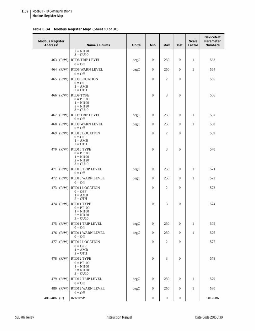
E.32
SEL-787 Relay Instruction Manual Date Code 20150130
Modbus RTU CommunicationsModbus Register Map
2 = NI1203 = CU10
463 (R/W) RTD8 TRIP LEVEL degC 0 250 0 1 5630 = Off
464 (R/W) RTD8 WARN LEVEL degC 0 250 0 1 5640 = Off
465 (R/W) RTD9 LOCATION 0 2 0 5650 = OFF1 = AMB2 = OTH
466 (R/W) RTD9 TYPE 0 3 0 5660 = PT1001 = NI1002 = NI1203 = CU10
467 (R/W) RTD9 TRIP LEVEL degC 0 250 0 1 5670 = Off
468 (R/W) RTD9 WARN LEVEL degC 0 250 0 1 5680 = Off
469 (R/W) RTD10 LOCATION 0 2 0 5690 = OFF1 = AMB2 = OTH
470 (R/W) RTD10 TYPE 0 3 0 5700 = PT1001 = NI1002 = NI1203 = CU10
471 (R/W) RTD10 TRIP LEVEL degC 0 250 0 1 5710 = Off
472 (R/W) RTD10 WARN LEVEL degC 0 250 0 1 5720 = Off
473 (R/W) RTD11 LOCATION 0 2 0 5730 = OFF1 = AMB2 = OTH
474 (R/W) RTD11 TYPE 0 3 0 5740 = PT1001 = NI1002 = NI1203 = CU10
475 (R/W) RTD11 TRIP LEVEL degC 0 250 0 1 5750 = Off
476 (R/W) RTD11 WARN LEVEL degC 0 250 0 1 5760 = Off
477 (R/W) RTD12 LOCATION 0 2 0 5770 = OFF1 = AMB2 = OTH
478 (R/W) RTD12 TYPE 0 3 0 5780 = PT1001 = NI1002 = NI1203 = CU10
479 (R/W) RTD12 TRIP LEVEL degC 0 250 0 1 5790 = Off
480 (R/W) RTD12 WARN LEVEL degC 0 250 0 1 5800 = Off
481–486 (R) Reservedc 0 0 0 581–586
Table E.34 Modbus Register Mapa (Sheet 10 of 36)
Modbus Register Addressb Name / Enums Units Min Max Def
Scale Factor
DeviceNet Parameter Numbers
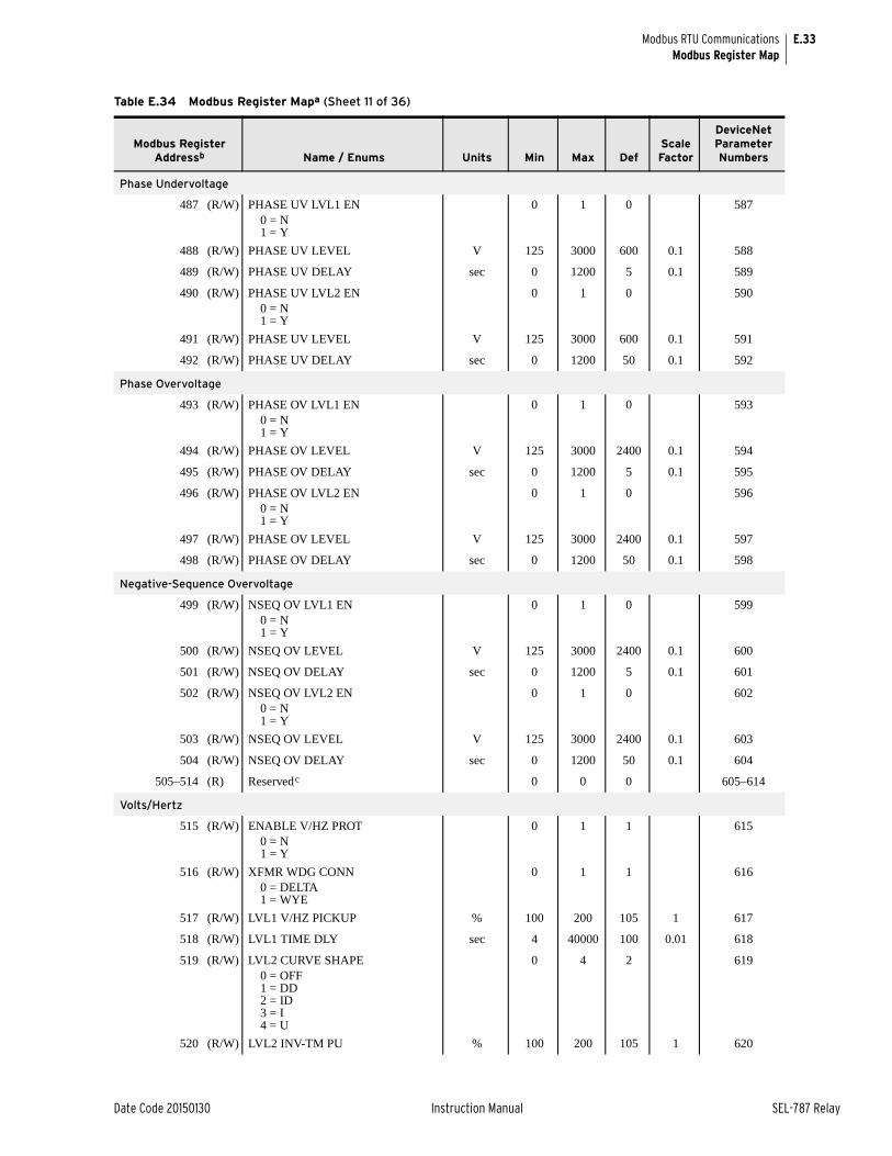
E.33
Date Code 20150130 Instruction Manual SEL-787 Relay
Modbus RTU CommunicationsModbus Register Map
Phase Undervoltage
487 (R/W) PHASE UV LVL1 EN 0 1 0 5870 = N1 = Y
488 (R/W) PHASE UV LEVEL V 125 3000 600 0.1 588
489 (R/W) PHASE UV DELAY sec 0 1200 5 0.1 589
490 (R/W) PHASE UV LVL2 EN 0 1 0 5900 = N1 = Y
491 (R/W) PHASE UV LEVEL V 125 3000 600 0.1 591
492 (R/W) PHASE UV DELAY sec 0 1200 50 0.1 592
Phase Overvoltage
493 (R/W) PHASE OV LVL1 EN 0 1 0 5930 = N1 = Y
494 (R/W) PHASE OV LEVEL V 125 3000 2400 0.1 594
495 (R/W) PHASE OV DELAY sec 0 1200 5 0.1 595
496 (R/W) PHASE OV LVL2 EN 0 1 0 5960 = N1 = Y
497 (R/W) PHASE OV LEVEL V 125 3000 2400 0.1 597
498 (R/W) PHASE OV DELAY sec 0 1200 50 0.1 598
Negative-Sequence Overvoltage
499 (R/W) NSEQ OV LVL1 EN 0 1 0 5990 = N1 = Y
500 (R/W) NSEQ OV LEVEL V 125 3000 2400 0.1 600
501 (R/W) NSEQ OV DELAY sec 0 1200 5 0.1 601
502 (R/W) NSEQ OV LVL2 EN 0 1 0 6020 = N1 = Y
503 (R/W) NSEQ OV LEVEL V 125 3000 2400 0.1 603
504 (R/W) NSEQ OV DELAY sec 0 1200 50 0.1 604
505–514 (R) Reservedc 0 0 0 605–614
Volts/Hertz
515 (R/W) ENABLE V/HZ PROT 0 1 1 6150 = N1 = Y
516 (R/W) XFMR WDG CONN 0 1 1 6160 = DELTA1 = WYE
517 (R/W) LVL1 V/HZ PICKUP % 100 200 105 1 617
518 (R/W) LVL1 TIME DLY sec 4 40000 100 0.01 618
519 (R/W) LVL2 CURVE SHAPE 0 4 2 6190 = OFF1 = DD2 = ID3 = I4 = U
520 (R/W) LVL2 INV-TM PU % 100 200 105 1 620
Table E.34 Modbus Register Mapa (Sheet 11 of 36)
Modbus Register Addressb Name / Enums Units Min Max Def
Scale Factor
DeviceNet Parameter Numbers
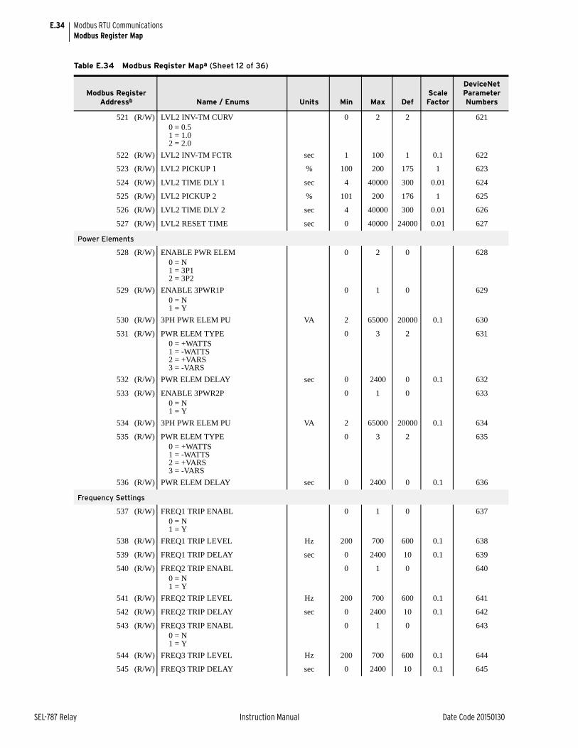
E.34
SEL-787 Relay Instruction Manual Date Code 20150130
Modbus RTU CommunicationsModbus Register Map
521 (R/W) LVL2 INV-TM CURV 0 2 2 6210 = 0.51 = 1.02 = 2.0
522 (R/W) LVL2 INV-TM FCTR sec 1 100 1 0.1 622
523 (R/W) LVL2 PICKUP 1 % 100 200 175 1 623
524 (R/W) LVL2 TIME DLY 1 sec 4 40000 300 0.01 624
525 (R/W) LVL2 PICKUP 2 % 101 200 176 1 625
526 (R/W) LVL2 TIME DLY 2 sec 4 40000 300 0.01 626
527 (R/W) LVL2 RESET TIME sec 0 40000 24000 0.01 627
Power Elements
528 (R/W) ENABLE PWR ELEM 0 2 0 6280 = N1 = 3P12 = 3P2
529 (R/W) ENABLE 3PWR1P 0 1 0 6290 = N1 = Y
530 (R/W) 3PH PWR ELEM PU VA 2 65000 20000 0.1 630
531 (R/W) PWR ELEM TYPE 0 3 2 6310 = +WATTS1 = -WATTS2 = +VARS3 = -VARS
532 (R/W) PWR ELEM DELAY sec 0 2400 0 0.1 632
533 (R/W) ENABLE 3PWR2P 0 1 0 6330 = N1 = Y
534 (R/W) 3PH PWR ELEM PU VA 2 65000 20000 0.1 634
535 (R/W) PWR ELEM TYPE 0 3 2 6350 = +WATTS1 = -WATTS2 = +VARS3 = -VARS
536 (R/W) PWR ELEM DELAY sec 0 2400 0 0.1 636
Frequency Settings
537 (R/W) FREQ1 TRIP ENABL 0 1 0 6370 = N1 = Y
538 (R/W) FREQ1 TRIP LEVEL Hz 200 700 600 0.1 638
539 (R/W) FREQ1 TRIP DELAY sec 0 2400 10 0.1 639
540 (R/W) FREQ2 TRIP ENABL 0 1 0 6400 = N1 = Y
541 (R/W) FREQ2 TRIP LEVEL Hz 200 700 600 0.1 641
542 (R/W) FREQ2 TRIP DELAY sec 0 2400 10 0.1 642
543 (R/W) FREQ3 TRIP ENABL 0 1 0 6430 = N1 = Y
544 (R/W) FREQ3 TRIP LEVEL Hz 200 700 600 0.1 644
545 (R/W) FREQ3 TRIP DELAY sec 0 2400 10 0.1 645
Table E.34 Modbus Register Mapa (Sheet 12 of 36)
Modbus Register Addressb Name / Enums Units Min Max Def
Scale Factor
DeviceNet Parameter Numbers
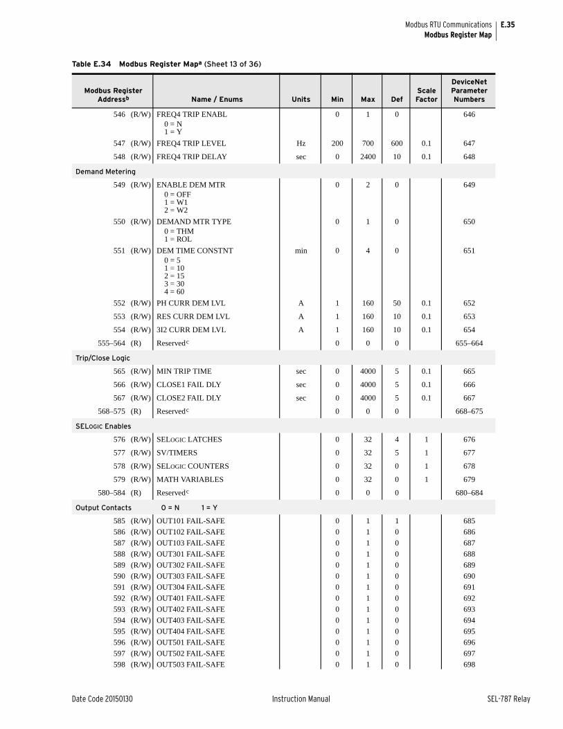
E.35
Date Code 20150130 Instruction Manual SEL-787 Relay
Modbus RTU CommunicationsModbus Register Map
546 (R/W) FREQ4 TRIP ENABL 0 1 0 6460 = N1 = Y
547 (R/W) FREQ4 TRIP LEVEL Hz 200 700 600 0.1 647
548 (R/W) FREQ4 TRIP DELAY sec 0 2400 10 0.1 648
Demand Metering
549 (R/W) ENABLE DEM MTR 0 2 0 6490 = OFF1 = W12 = W2
550 (R/W) DEMAND MTR TYPE 0 1 0 6500 = THM1 = ROL
551 (R/W) DEM TIME CONSTNT min 0 4 0 6510 = 51 = 102 = 153 = 304 = 60
552 (R/W) PH CURR DEM LVL A 1 160 50 0.1 652
553 (R/W) RES CURR DEM LVL A 1 160 10 0.1 653
554 (R/W) 3I2 CURR DEM LVL A 1 160 10 0.1 654
555–564 (R) Reservedc 0 0 0 655–664
Trip/Close Logic
565 (R/W) MIN TRIP TIME sec 0 4000 5 0.1 665
566 (R/W) CLOSE1 FAIL DLY sec 0 4000 5 0.1 666
567 (R/W) CLOSE2 FAIL DLY sec 0 4000 5 0.1 667
568–575 (R) Reservedc 0 0 0 668–675
SELOGIC Enables
576 (R/W) SELOGIC LATCHES 0 32 4 1 676
577 (R/W) SV/TIMERS 0 32 5 1 677
578 (R/W) SELOGIC COUNTERS 0 32 0 1 678
579 (R/W) MATH VARIABLES 0 32 0 1 679
580–584 (R) Reservedc 0 0 0 680–684
Output Contacts 0 = N 1 = Y
585 (R/W) OUT101 FAIL-SAFE 0 1 1 685
586 (R/W) OUT102 FAIL-SAFE 0 1 0 686
587 (R/W) OUT103 FAIL-SAFE 0 1 0 687
588 (R/W) OUT301 FAIL-SAFE 0 1 0 688
589 (R/W) OUT302 FAIL-SAFE 0 1 0 689
590 (R/W) OUT303 FAIL-SAFE 0 1 0 690
591 (R/W) OUT304 FAIL-SAFE 0 1 0 691
592 (R/W) OUT401 FAIL-SAFE 0 1 0 692
593 (R/W) OUT402 FAIL-SAFE 0 1 0 693
594 (R/W) OUT403 FAIL-SAFE 0 1 0 694
595 (R/W) OUT404 FAIL-SAFE 0 1 0 695
596 (R/W) OUT501 FAIL-SAFE 0 1 0 696
597 (R/W) OUT502 FAIL-SAFE 0 1 0 697
598 (R/W) OUT503 FAIL-SAFE 0 1 0 698
Table E.34 Modbus Register Mapa (Sheet 13 of 36)
Modbus Register Addressb Name / Enums Units Min Max Def
Scale Factor
DeviceNet Parameter Numbers
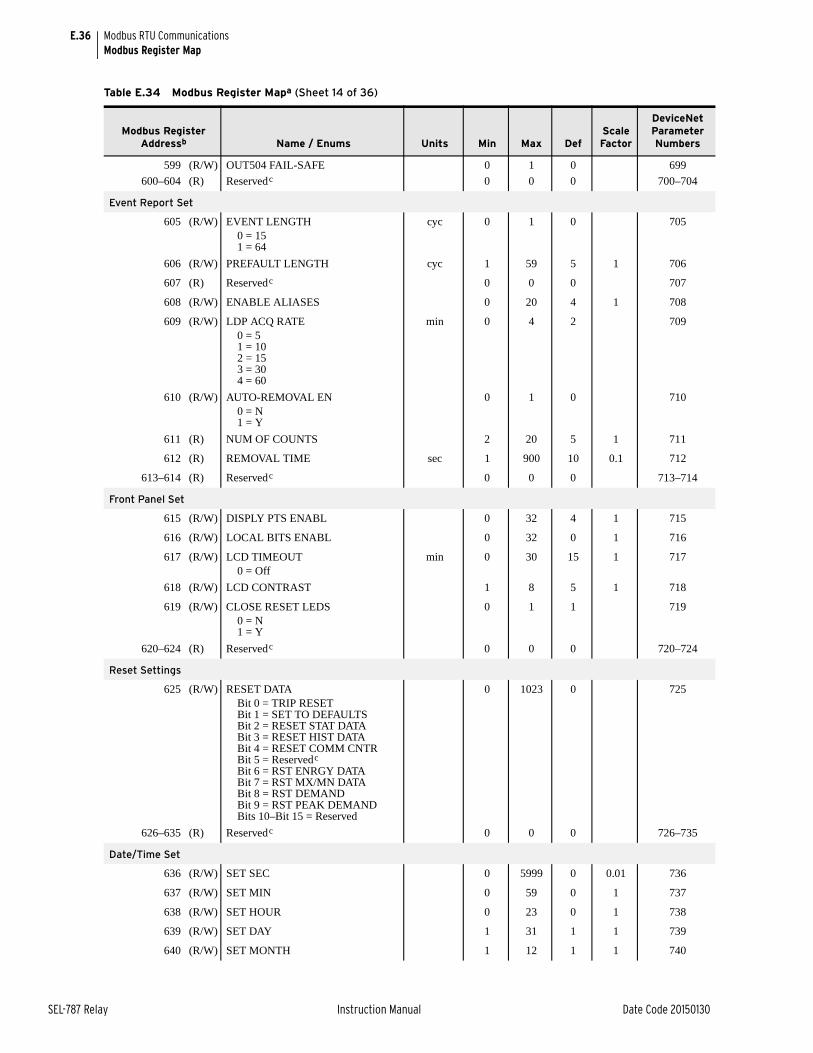
E.36
SEL-787 Relay Instruction Manual Date Code 20150130
Modbus RTU CommunicationsModbus Register Map
599 (R/W) OUT504 FAIL-SAFE 0 1 0 699
600–604 (R) Reservedc 0 0 0 700–704
Event Report Set
605 (R/W) EVENT LENGTH cyc 0 1 0 7050 = 151 = 64
606 (R/W) PREFAULT LENGTH cyc 1 59 5 1 706
607 (R) Reservedc 0 0 0 707
608 (R/W) ENABLE ALIASES 0 20 4 1 708
609 (R/W) LDP ACQ RATE min 0 4 2 7090 = 51 = 102 = 153 = 304 = 60
610 (R/W) AUTO-REMOVAL EN 0 1 0 7100 = N1 = Y
611 (R) NUM OF COUNTS 2 20 5 1 711
612 (R) REMOVAL TIME sec 1 900 10 0.1 712
613–614 (R) Reservedc 0 0 0 713–714
Front Panel Set
615 (R/W) DISPLY PTS ENABL 0 32 4 1 715
616 (R/W) LOCAL BITS ENABL 0 32 0 1 716
617 (R/W) LCD TIMEOUT min 0 30 15 1 7170 = Off
618 (R/W) LCD CONTRAST 1 8 5 1 718
619 (R/W) CLOSE RESET LEDS 0 1 1 7190 = N1 = Y
620–624 (R) Reservedc 0 0 0 720–724
Reset Settings
625 (R/W) RESET DATA 0 1023 0 725Bit 0 = TRIP RESETBit 1 = SET TO DEFAULTSBit 2 = RESET STAT DATABit 3 = RESET HIST DATABit 4 = RESET COMM CNTRBit 5 = Reservedc
Bit 6 = RST ENRGY DATABit 7 = RST MX/MN DATABit 8 = RST DEMANDBit 9 = RST PEAK DEMANDBits 10–Bit 15 = Reserved
626–635 (R) Reservedc 0 0 0 726–735
Date/Time Set
636 (R/W) SET SEC 0 5999 0 0.01 736
637 (R/W) SET MIN 0 59 0 1 737
638 (R/W) SET HOUR 0 23 0 1 738
639 (R/W) SET DAY 1 31 1 1 739
640 (R/W) SET MONTH 1 12 1 1 740
Table E.34 Modbus Register Mapa (Sheet 14 of 36)
Modbus Register Addressb Name / Enums Units Min Max Def
Scale Factor
DeviceNet Parameter Numbers
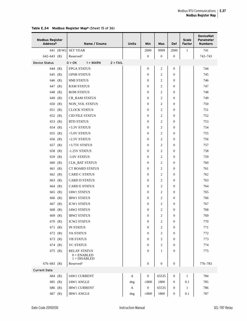
E.37
Date Code 20150130 Instruction Manual SEL-787 Relay
Modbus RTU CommunicationsModbus Register Map
641 (R/W) SET YEAR 2000 9999 2000 1 741
642–643 (R) Reservedc 0 0 0 742–743
Device Status 0 = OK 1 = WARN 2 = FAIL
644 (R) FPGA STATUS 0 2 0 744
645 (R) GPSB STATUS 0 2 0 745
646 (R) HMI STATUS 0 2 0 746
647 (R) RAM STATUS 0 2 0 747
648 (R) ROM STATUS 0 2 0 748
649 (R) CR_RAM STATUS 0 2 0 749
650 (R) NON_VOL STATUS 0 2 0 750
651 (R) CLOCK STATUS 0 2 0 751
652 (R) CID FILE STATUS 0 2 0 752
653 (R) RTD STATUS 0 2 0 753
654 (R) +3.3V STATUS 0 2 0 754
655 (R) +5.0V STATUS 0 2 0 755
656 (R) +2.5V STATUS 0 2 0 756
657 (R) +3.75V STATUS 0 2 0 757
658 (R) -1.25V STATUS 0 2 0 758
659 (R) -5.0V STATUS 0 2 0 759
660 (R) CLK_BAT STATUS 0 2 0 760
661 (R) CT BOARD STATUS 0 2 0 761
662 (R) CARD C STATUS 0 2 0 762
663 (R) CARD D STATUS 0 2 0 763
664 (R) CARD E STATUS 0 2 0 764
665 (R) IAW1 STATUS 0 2 0 765
666 (R) IBW1 STATUS 0 2 0 766
667 (R) ICW1 STATUS 0 2 0 767
668 (R) IAW2 STATUS 0 2 0 768
669 (R) IBW2 STATUS 0 2 0 769
670 (R) ICW2 STATUS 0 2 0 770
671 (R) IN STATUS 0 2 0 771
672 (R) VA STATUS 0 2 0 772
673 (R) VB STATUS 0 2 0 773
674 (R) VC STATUS 0 2 0 774
675 (R) RELAY STATUS 0 1 0 7750 = ENABLED1 = DISABLED
676–683 (R) Reservedc 0 0 0 776–783
Current Data
684 (R) IAW1 CURRENT A 0 65535 0 1 784
685 (R) IAW1 ANGLE deg -1800 1800 0 0.1 785
686 (R) IBW1 CURRENT A 0 65535 0 1 786
687 (R) IBW1 ANGLE deg -1800 1800 0 0.1 787
Table E.34 Modbus Register Mapa (Sheet 15 of 36)
Modbus Register Addressb Name / Enums Units Min Max Def
Scale Factor
DeviceNet Parameter Numbers
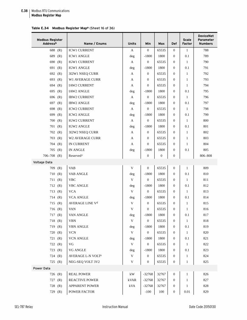
E.38
SEL-787 Relay Instruction Manual Date Code 20150130
Modbus RTU CommunicationsModbus Register Map
688 (R) ICW1 CURRENT A 0 65535 0 1 788
689 (R) ICW1 ANGLE deg -1800 1800 0 0.1 789
690 (R) IGW1 CURRENT A 0 65535 0 1 790
691 (R) IGW1 ANGLE deg -1800 1800 0 0.1 791
692 (R) 3I2W1 NSEQ CURR A 0 65535 0 1 792
693 (R) W1 AVERAGE CURR A 0 65535 0 1 793
694 (R) IAW2 CURRENT A 0 65535 0 1 794
695 (R) IAW2 ANGLE deg -1800 1800 0 0.1 795
696 (R) IBW2 CURRENT A 0 65535 0 1 796
697 (R) IBW2 ANGLE deg -1800 1800 0 0.1 797
698 (R) ICW2 CURRENT A 0 65535 0 1 798
699 (R) ICW2 ANGLE deg -1800 1800 0 0.1 799
700 (R) IGW2 CURRENT A 0 65535 0 1 800
701 (R) IGW2 ANGLE deg -1800 1800 0 0.1 801
702 (R) 3I2W2 NSEQ CURR A 0 65535 0 1 802
703 (R) W2 AVERAGE CURR A 0 65535 0 1 803
704 (R) IN CURRENT A 0 65535 0 1 804
705 (R) IN ANGLE deg -1800 1800 0 0.1 805
706–708 (R) Reservedc 0 0 0 806–808
Voltage Data
709 (R) VAB V 0 65535 0 1 809
710 (R) VAB ANGLE deg -1800 1800 0 0.1 810
711 (R) VBC V 0 65535 0 1 811
712 (R) VBC ANGLE deg -1800 1800 0 0.1 812
713 (R) VCA V 0 65535 0 1 813
714 (R) VCA ANGLE deg -1800 1800 0 0.1 814
715 (R) AVERAGE LINE Vd V 0 65535 0 1 815
716 (R) VAN V 0 65535 0 1 816
717 (R) VAN ANGLE deg -1800 1800 0 0.1 817
718 (R) VBN V 0 65535 0 1 818
719 (R) VBN ANGLE deg -1800 1800 0 0.1 819
720 (R) VCN V 0 65535 0 1 820
721 (R) VCN ANGLE deg -1800 1800 0 0.1 821
722 (R) VG V 0 65535 0 1 822
723 (R) VG ANGLE deg -1800 1800 0 0.1 823
724 (R) AVERAGE L-N VOLTe V 0 65535 0 1 824
725 (R) NEG-SEQ VOLT 3V2 V 0 65535 0 1 825
Power Data
726 (R) REAL POWER kW -32768 32767 0 1 826
727 (R) REACTIVE POWER kVAR -32768 32767 0 1 827
728 (R) APPARENT POWER kVA -32768 32767 0 1 828
729 (R) POWER FACTOR -100 100 0 0.01 829
Table E.34 Modbus Register Mapa (Sheet 16 of 36)
Modbus Register Addressb Name / Enums Units Min Max Def
Scale Factor
DeviceNet Parameter Numbers
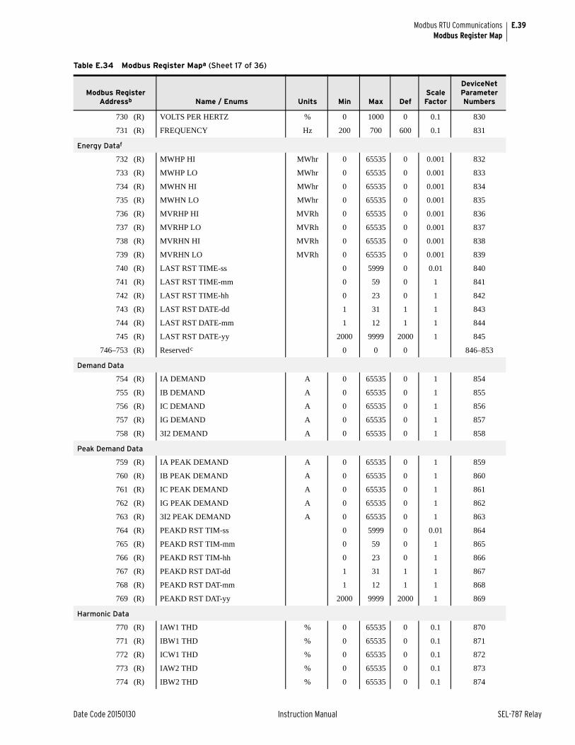
E.39
Date Code 20150130 Instruction Manual SEL-787 Relay
Modbus RTU CommunicationsModbus Register Map
730 (R) VOLTS PER HERTZ % 0 1000 0 0.1 830
731 (R) FREQUENCY Hz 200 700 600 0.1 831
Energy Dataf
732 (R) MWHP HI MWhr 0 65535 0 0.001 832
733 (R) MWHP LO MWhr 0 65535 0 0.001 833
734 (R) MWHN HI MWhr 0 65535 0 0.001 834
735 (R) MWHN LO MWhr 0 65535 0 0.001 835
736 (R) MVRHP HI MVRh 0 65535 0 0.001 836
737 (R) MVRHP LO MVRh 0 65535 0 0.001 837
738 (R) MVRHN HI MVRh 0 65535 0 0.001 838
739 (R) MVRHN LO MVRh 0 65535 0 0.001 839
740 (R) LAST RST TIME-ss 0 5999 0 0.01 840
741 (R) LAST RST TIME-mm 0 59 0 1 841
742 (R) LAST RST TIME-hh 0 23 0 1 842
743 (R) LAST RST DATE-dd 1 31 1 1 843
744 (R) LAST RST DATE-mm 1 12 1 1 844
745 (R) LAST RST DATE-yy 2000 9999 2000 1 845
746–753 (R) Reservedc 0 0 0 846–853
Demand Data
754 (R) IA DEMAND A 0 65535 0 1 854
755 (R) IB DEMAND A 0 65535 0 1 855
756 (R) IC DEMAND A 0 65535 0 1 856
757 (R) IG DEMAND A 0 65535 0 1 857
758 (R) 3I2 DEMAND A 0 65535 0 1 858
Peak Demand Data
759 (R) IA PEAK DEMAND A 0 65535 0 1 859
760 (R) IB PEAK DEMAND A 0 65535 0 1 860
761 (R) IC PEAK DEMAND A 0 65535 0 1 861
762 (R) IG PEAK DEMAND A 0 65535 0 1 862
763 (R) 3I2 PEAK DEMAND A 0 65535 0 1 863
764 (R) PEAKD RST TIM-ss 0 5999 0 0.01 864
765 (R) PEAKD RST TIM-mm 0 59 0 1 865
766 (R) PEAKD RST TIM-hh 0 23 0 1 866
767 (R) PEAKD RST DAT-dd 1 31 1 1 867
768 (R) PEAKD RST DAT-mm 1 12 1 1 868
769 (R) PEAKD RST DAT-yy 2000 9999 2000 1 869
Harmonic Data
770 (R) IAW1 THD % 0 65535 0 0.1 870
771 (R) IBW1 THD % 0 65535 0 0.1 871
772 (R) ICW1 THD % 0 65535 0 0.1 872
773 (R) IAW2 THD % 0 65535 0 0.1 873
774 (R) IBW2 THD % 0 65535 0 0.1 874
Table E.34 Modbus Register Mapa (Sheet 17 of 36)
Modbus Register Addressb Name / Enums Units Min Max Def
Scale Factor
DeviceNet Parameter Numbers
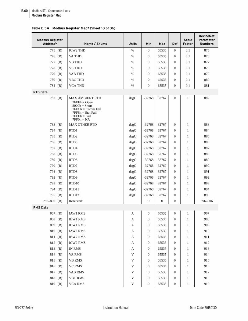
E.40
SEL-787 Relay Instruction Manual Date Code 20150130
Modbus RTU CommunicationsModbus Register Map
775 (R) ICW2 THD % 0 65535 0 0.1 875
776 (R) VA THD % 0 65535 0 0.1 876
777 (R) VB THD % 0 65535 0 0.1 877
778 (R) VC THD % 0 65535 0 0.1 878
779 (R) VAB THD % 0 65535 0 0.1 879
780 (R) VBC THD % 0 65535 0 0.1 880
781 (R) VCA THD % 0 65535 0 0.1 881
RTD Data
782 (R) MAX AMBIENT RTD degC -32768 32767 0 1 8827FFFh = Open8000h = Short7FFCh = Comm Fail7FF8h = Stat Fail7FFEh = Fail7FF0h = NA
783 (R) MAX OTHER RTD degC -32768 32767 0 1 883
784 (R) RTD1 degC -32768 32767 0 1 884
785 (R) RTD2 degC -32768 32767 0 1 885
786 (R) RTD3 degC -32768 32767 0 1 886
787 (R) RTD4 degC -32768 32767 0 1 887
788 (R) RTD5 degC -32768 32767 0 1 888
789 (R) RTD6 degC -32768 32767 0 1 889
790 (R) RTD7 degC -32768 32767 0 1 890
791 (R) RTD8 degC -32768 32767 0 1 891
792 (R) RTD9 degC -32768 32767 0 1 892
793 (R) RTD10 degC -32768 32767 0 1 893
794 (R) RTD11 degC -32768 32767 0 1 894
795 (R) RTD12 degC -32768 32767 0 1 895
796–806 (R) Reservedc 0 0 0 896–906
RMS Data
807 (R) IAW1 RMS A 0 65535 0 1 907
808 (R) IBW1 RMS A 0 65535 0 1 908
809 (R) ICW1 RMS A 0 65535 0 1 909
810 (R) IAW2 RMS A 0 65535 0 1 910
811 (R) IBW2 RMS A 0 65535 0 1 911
812 (R) ICW2 RMS A 0 65535 0 1 912
813 (R) IN RMS A 0 65535 0 1 913
814 (R) VA RMS V 0 65535 0 1 914
815 (R) VB RMS V 0 65535 0 1 915
816 (R) VC RMS V 0 65535 0 1 916
817 (R) VAB RMS V 0 65535 0 1 917
818 (R) VBC RMS V 0 65535 0 1 918
819 (R) VCA RMS V 0 65535 0 1 919
Table E.34 Modbus Register Mapa (Sheet 18 of 36)
Modbus Register Addressb Name / Enums Units Min Max Def
Scale Factor
DeviceNet Parameter Numbers
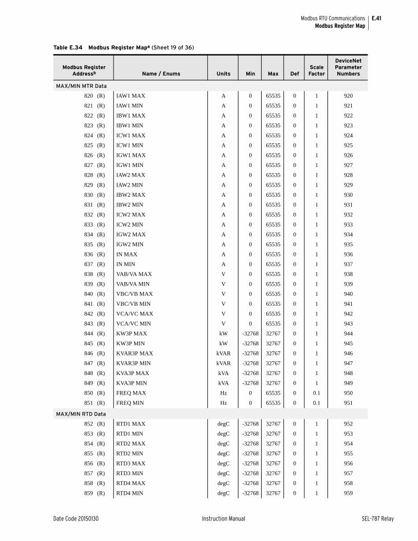
E.41
Date Code 20150130 Instruction Manual SEL-787 Relay
Modbus RTU CommunicationsModbus Register Map
MAX/MIN MTR Data
820 (R) IAW1 MAX A 0 65535 0 1 920
821 (R) IAW1 MIN A 0 65535 0 1 921
822 (R) IBW1 MAX A 0 65535 0 1 922
823 (R) IBW1 MIN A 0 65535 0 1 923
824 (R) ICW1 MAX A 0 65535 0 1 924
825 (R) ICW1 MIN A 0 65535 0 1 925
826 (R) IGW1 MAX A 0 65535 0 1 926
827 (R) IGW1 MIN A 0 65535 0 1 927
828 (R) IAW2 MAX A 0 65535 0 1 928
829 (R) IAW2 MIN A 0 65535 0 1 929
830 (R) IBW2 MAX A 0 65535 0 1 930
831 (R) IBW2 MIN A 0 65535 0 1 931
832 (R) ICW2 MAX A 0 65535 0 1 932
833 (R) ICW2 MIN A 0 65535 0 1 933
834 (R) IGW2 MAX A 0 65535 0 1 934
835 (R) IGW2 MIN A 0 65535 0 1 935
836 (R) IN MAX A 0 65535 0 1 936
837 (R) IN MIN A 0 65535 0 1 937
838 (R) VAB/VA MAX V 0 65535 0 1 938
839 (R) VAB/VA MIN V 0 65535 0 1 939
840 (R) VBC/VB MAX V 0 65535 0 1 940
841 (R) VBC/VB MIN V 0 65535 0 1 941
842 (R) VCA/VC MAX V 0 65535 0 1 942
843 (R) VCA/VC MIN V 0 65535 0 1 943
844 (R) KW3P MAX kW -32768 32767 0 1 944
845 (R) KW3P MIN kW -32768 32767 0 1 945
846 (R) KVAR3P MAX kVAR -32768 32767 0 1 946
847 (R) KVAR3P MIN kVAR -32768 32767 0 1 947
848 (R) KVA3P MAX kVA -32768 32767 0 1 948
849 (R) KVA3P MIN kVA -32768 32767 0 1 949
850 (R) FREQ MAX Hz 0 65535 0 0.1 950
851 (R) FREQ MIN Hz 0 65535 0 0.1 951
MAX/MIN RTD Data
852 (R) RTD1 MAX degC -32768 32767 0 1 952
853 (R) RTD1 MIN degC -32768 32767 0 1 953
854 (R) RTD2 MAX degC -32768 32767 0 1 954
855 (R) RTD2 MIN degC -32768 32767 0 1 955
856 (R) RTD3 MAX degC -32768 32767 0 1 956
857 (R) RTD3 MIN degC -32768 32767 0 1 957
858 (R) RTD4 MAX degC -32768 32767 0 1 958
859 (R) RTD4 MIN degC -32768 32767 0 1 959
Table E.34 Modbus Register Mapa (Sheet 19 of 36)
Modbus Register Addressb Name / Enums Units Min Max Def
Scale Factor
DeviceNet Parameter Numbers
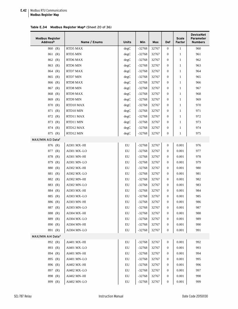
E.42
SEL-787 Relay Instruction Manual Date Code 20150130
Modbus RTU CommunicationsModbus Register Map
860 (R) RTD5 MAX degC -32768 32767 0 1 960
861 (R) RTD5 MIN degC -32768 32767 0 1 961
862 (R) RTD6 MAX degC -32768 32767 0 1 962
863 (R) RTD6 MIN degC -32768 32767 0 1 963
864 (R) RTD7 MAX degC -32768 32767 0 1 964
865 (R) RTD7 MIN degC -32768 32767 0 1 965
866 (R) RTD8 MAX degC -32768 32767 0 1 966
867 (R) RTD8 MIN degC -32768 32767 0 1 967
868 (R) RTD9 MAX degC -32768 32767 0 1 968
869 (R) RTD9 MIN degC -32768 32767 0 1 969
870 (R) RTD10 MAX degC -32768 32767 0 1 970
871 (R) RTD10 MIN degC -32768 32767 0 1 971
872 (R) RTD11 MAX degC -32768 32767 0 1 972
873 (R) RTD11 MIN degC -32768 32767 0 1 973
874 (R) RTD12 MAX degC -32768 32767 0 1 974
875 (R) RTD12 MIN degC -32768 32767 0 1 975
MAX/MIN AI3 Dataf
876 (R) AI301 MX–HI EU -32768 32767 0 0.001 976
877 (R) AI301 MX–LO EU -32768 32767 0 0.001 977
878 (R) AI301 MN–HI EU -32768 32767 0 0.001 978
879 (R) AI301 MN–LO EU -32768 32767 0 0.001 979
880 (R) AI302 MX–HI EU -32768 32767 0 0.001 980
881 (R) AI302 MX–LO EU -32768 32767 0 0.001 981
882 (R) AI302 MN–HI EU -32768 32767 0 0.001 982
883 (R) AI302 MN–LO EU -32768 32767 0 0.001 983
884 (R) AI303 MX–HI EU -32768 32767 0 0.001 984
885 (R) AI303 MX–LO EU -32768 32767 0 0.001 985
886 (R) AI303 MN–HI EU -32768 32767 0 0.001 986
887 (R) AI303 MN–LO EU -32768 32767 0 0.001 987
888 (R) AI304 MX–HI EU -32768 32767 0 0.001 988
889 (R) AI304 MX–LO EU -32768 32767 0 0.001 989
890 (R) AI304 MN–HI EU -32768 32767 0 0.001 990
891 (R) AI304 MN–LO EU -32768 32767 0 0.001 991
MAX/MIN AI4 Dataf
892 (R) AI401 MX–HI EU -32768 32767 0 0.001 992
893 (R) AI401 MX–LO EU -32768 32767 0 0.001 993
894 (R) AI401 MN–HI EU -32768 32767 0 0.001 994
895 (R) AI401 MN–LO EU -32768 32767 0 0.001 995
896 (R) AI402 MX–HI EU -32768 32767 0 0.001 996
897 (R) AI402 MX–LO EU -32768 32767 0 0.001 997
898 (R) AI402 MN–HI EU -32768 32767 0 0.001 998
899 (R) AI402 MN–LO EU -32768 32767 0 0.001 999
Table E.34 Modbus Register Mapa (Sheet 20 of 36)
Modbus Register Addressb Name / Enums Units Min Max Def
Scale Factor
DeviceNet Parameter Numbers
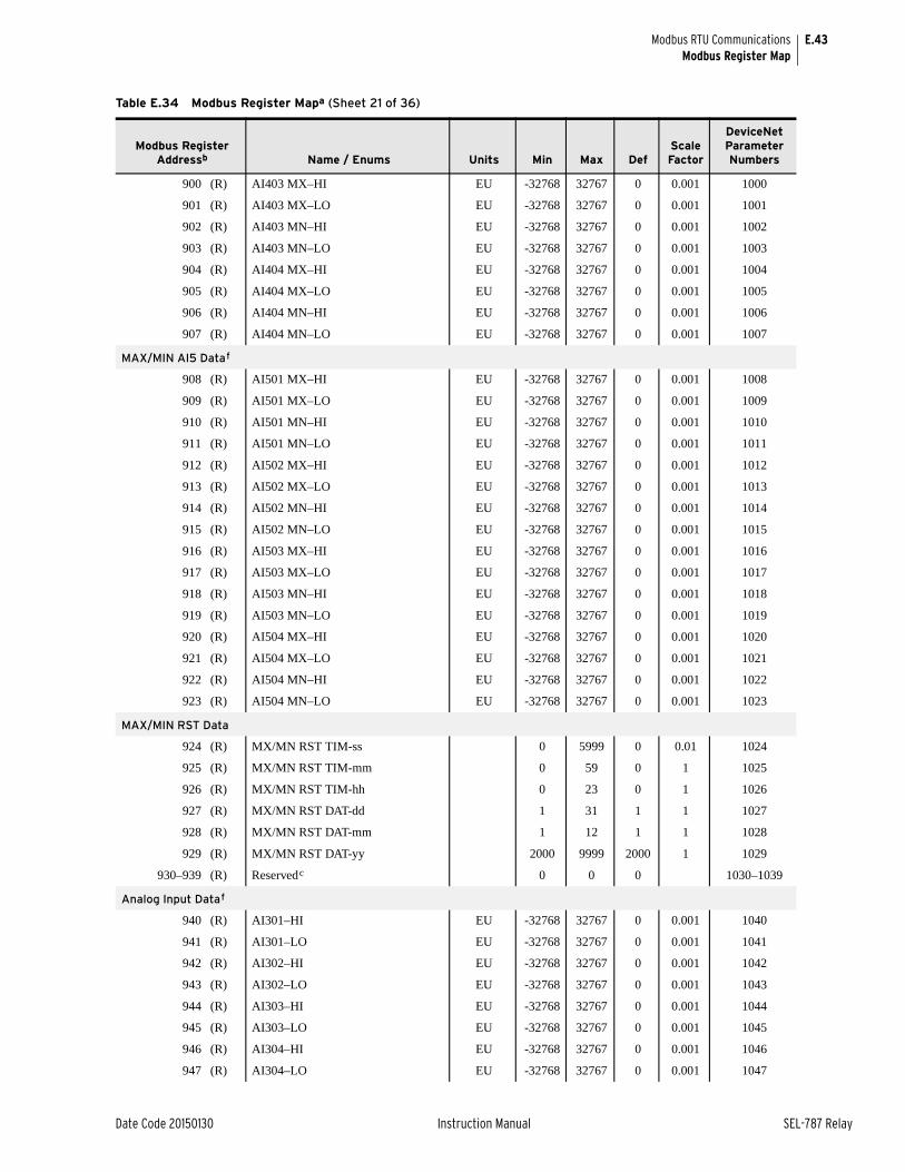
E.43
Date Code 20150130 Instruction Manual SEL-787 Relay
Modbus RTU CommunicationsModbus Register Map
900 (R) AI403 MX–HI EU -32768 32767 0 0.001 1000
901 (R) AI403 MX–LO EU -32768 32767 0 0.001 1001
902 (R) AI403 MN–HI EU -32768 32767 0 0.001 1002
903 (R) AI403 MN–LO EU -32768 32767 0 0.001 1003
904 (R) AI404 MX–HI EU -32768 32767 0 0.001 1004
905 (R) AI404 MX–LO EU -32768 32767 0 0.001 1005
906 (R) AI404 MN–HI EU -32768 32767 0 0.001 1006
907 (R) AI404 MN–LO EU -32768 32767 0 0.001 1007
MAX/MIN AI5 Dataf
908 (R) AI501 MX–HI EU -32768 32767 0 0.001 1008
909 (R) AI501 MX–LO EU -32768 32767 0 0.001 1009
910 (R) AI501 MN–HI EU -32768 32767 0 0.001 1010
911 (R) AI501 MN–LO EU -32768 32767 0 0.001 1011
912 (R) AI502 MX–HI EU -32768 32767 0 0.001 1012
913 (R) AI502 MX–LO EU -32768 32767 0 0.001 1013
914 (R) AI502 MN–HI EU -32768 32767 0 0.001 1014
915 (R) AI502 MN–LO EU -32768 32767 0 0.001 1015
916 (R) AI503 MX–HI EU -32768 32767 0 0.001 1016
917 (R) AI503 MX–LO EU -32768 32767 0 0.001 1017
918 (R) AI503 MN–HI EU -32768 32767 0 0.001 1018
919 (R) AI503 MN–LO EU -32768 32767 0 0.001 1019
920 (R) AI504 MX–HI EU -32768 32767 0 0.001 1020
921 (R) AI504 MX–LO EU -32768 32767 0 0.001 1021
922 (R) AI504 MN–HI EU -32768 32767 0 0.001 1022
923 (R) AI504 MN–LO EU -32768 32767 0 0.001 1023
MAX/MIN RST Data
924 (R) MX/MN RST TIM-ss 0 5999 0 0.01 1024
925 (R) MX/MN RST TIM-mm 0 59 0 1 1025
926 (R) MX/MN RST TIM-hh 0 23 0 1 1026
927 (R) MX/MN RST DAT-dd 1 31 1 1 1027
928 (R) MX/MN RST DAT-mm 1 12 1 1 1028
929 (R) MX/MN RST DAT-yy 2000 9999 2000 1 1029
930–939 (R) Reservedc 0 0 0 1030–1039
Analog Input Dataf
940 (R) AI301–HI EU -32768 32767 0 0.001 1040
941 (R) AI301–LO EU -32768 32767 0 0.001 1041
942 (R) AI302–HI EU -32768 32767 0 0.001 1042
943 (R) AI302–LO EU -32768 32767 0 0.001 1043
944 (R) AI303–HI EU -32768 32767 0 0.001 1044
945 (R) AI303–LO EU -32768 32767 0 0.001 1045
946 (R) AI304–HI EU -32768 32767 0 0.001 1046
947 (R) AI304–LO EU -32768 32767 0 0.001 1047
Table E.34 Modbus Register Mapa (Sheet 21 of 36)
Modbus Register Addressb Name / Enums Units Min Max Def
Scale Factor
DeviceNet Parameter Numbers
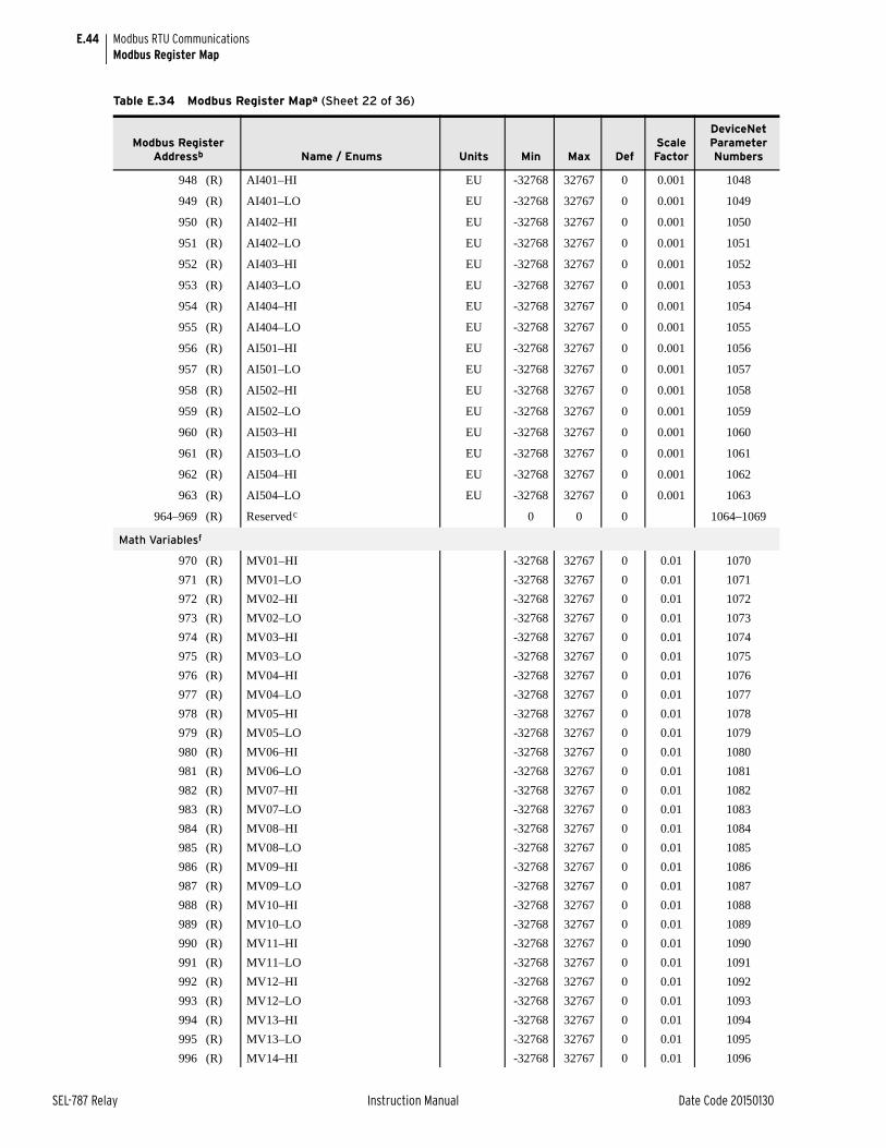
E.44
SEL-787 Relay Instruction Manual Date Code 20150130
Modbus RTU CommunicationsModbus Register Map
948 (R) AI401–HI EU -32768 32767 0 0.001 1048
949 (R) AI401–LO EU -32768 32767 0 0.001 1049
950 (R) AI402–HI EU -32768 32767 0 0.001 1050
951 (R) AI402–LO EU -32768 32767 0 0.001 1051
952 (R) AI403–HI EU -32768 32767 0 0.001 1052
953 (R) AI403–LO EU -32768 32767 0 0.001 1053
954 (R) AI404–HI EU -32768 32767 0 0.001 1054
955 (R) AI404–LO EU -32768 32767 0 0.001 1055
956 (R) AI501–HI EU -32768 32767 0 0.001 1056
957 (R) AI501–LO EU -32768 32767 0 0.001 1057
958 (R) AI502–HI EU -32768 32767 0 0.001 1058
959 (R) AI502–LO EU -32768 32767 0 0.001 1059
960 (R) AI503–HI EU -32768 32767 0 0.001 1060
961 (R) AI503–LO EU -32768 32767 0 0.001 1061
962 (R) AI504–HI EU -32768 32767 0 0.001 1062
963 (R) AI504–LO EU -32768 32767 0 0.001 1063
964–969 (R) Reservedc 0 0 0 1064–1069
Math Variablesf
970 (R) MV01–HI -32768 32767 0 0.01 1070
971 (R) MV01–LO -32768 32767 0 0.01 1071
972 (R) MV02–HI -32768 32767 0 0.01 1072
973 (R) MV02–LO -32768 32767 0 0.01 1073
974 (R) MV03–HI -32768 32767 0 0.01 1074
975 (R) MV03–LO -32768 32767 0 0.01 1075
976 (R) MV04–HI -32768 32767 0 0.01 1076
977 (R) MV04–LO -32768 32767 0 0.01 1077
978 (R) MV05–HI -32768 32767 0 0.01 1078
979 (R) MV05–LO -32768 32767 0 0.01 1079
980 (R) MV06–HI -32768 32767 0 0.01 1080
981 (R) MV06–LO -32768 32767 0 0.01 1081
982 (R) MV07–HI -32768 32767 0 0.01 1082
983 (R) MV07–LO -32768 32767 0 0.01 1083
984 (R) MV08–HI -32768 32767 0 0.01 1084
985 (R) MV08–LO -32768 32767 0 0.01 1085
986 (R) MV09–HI -32768 32767 0 0.01 1086
987 (R) MV09–LO -32768 32767 0 0.01 1087
988 (R) MV10–HI -32768 32767 0 0.01 1088
989 (R) MV10–LO -32768 32767 0 0.01 1089
990 (R) MV11–HI -32768 32767 0 0.01 1090
991 (R) MV11–LO -32768 32767 0 0.01 1091
992 (R) MV12–HI -32768 32767 0 0.01 1092
993 (R) MV12–LO -32768 32767 0 0.01 1093
994 (R) MV13–HI -32768 32767 0 0.01 1094
995 (R) MV13–LO -32768 32767 0 0.01 1095
996 (R) MV14–HI -32768 32767 0 0.01 1096
Table E.34 Modbus Register Mapa (Sheet 22 of 36)
Modbus Register Addressb Name / Enums Units Min Max Def
Scale Factor
DeviceNet Parameter Numbers
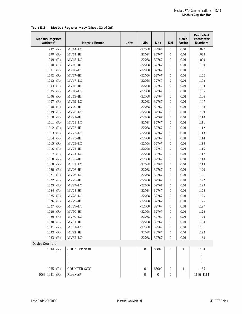
E.45
Date Code 20150130 Instruction Manual SEL-787 Relay
Modbus RTU CommunicationsModbus Register Map
997 (R) MV14–LO -32768 32767 0 0.01 1097
998 (R) MV15–HI -32768 32767 0 0.01 1098
999 (R) MV15–LO -32768 32767 0 0.01 1099
1000 (R) MV16–HI -32768 32767 0 0.01 1100
1001 (R) MV16–LO -32768 32767 0 0.01 1101
1002 (R) MV17–HI -32768 32767 0 0.01 1102
1003 (R) MV17–LO -32768 32767 0 0.01 1103
1004 (R) MV18–HI -32768 32767 0 0.01 1104
1005 (R) MV18–LO -32768 32767 0 0.01 1105
1006 (R) MV19–HI -32768 32767 0 0.01 1106
1007 (R) MV19–LO -32768 32767 0 0.01 1107
1008 (R) MV20–HI -32768 32767 0 0.01 1108
1009 (R) MV20–LO -32768 32767 0 0.01 1109
1010 (R) MV21–HI -32768 32767 0 0.01 1110
1011 (R) MV21–LO -32768 32767 0 0.01 1111
1012 (R) MV22–HI -32768 32767 0 0.01 1112
1013 (R) MV22–LO -32768 32767 0 0.01 1113
1014 (R) MV23–HI -32768 32767 0 0.01 1114
1015 (R) MV23–LO -32768 32767 0 0.01 1115
1016 (R) MV24–HI -32768 32767 0 0.01 1116
1017 (R) MV24–LO -32768 32767 0 0.01 1117
1018 (R) MV25–HI -32768 32767 0 0.01 1118
1019 (R) MV25–LO -32768 32767 0 0.01 1119
1020 (R) MV26–HI -32768 32767 0 0.01 1120
1021 (R) MV26–LO -32768 32767 0 0.01 1121
1022 (R) MV27–HI -32768 32767 0 0.01 1122
1023 (R) MV27–LO -32768 32767 0 0.01 1123
1024 (R) MV28–HI -32768 32767 0 0.01 1124
1025 (R) MV28–LO -32768 32767 0 0.01 1125
1026 (R) MV29–HI -32768 32767 0 0.01 1126
1027 (R) MV29–LO -32768 32767 0 0.01 1127
1028 (R) MV30–HI -32768 32767 0 0.01 1128
1029 (R) MV30–LO -32768 32767 0 0.01 1129
1030 (R) MV31–HI -32768 32767 0 0.01 1130
1031 (R) MV31–LO -32768 32767 0 0.01 1131
1032 (R) MV32–HI -32768 32767 0 0.01 1132
1033 (R) MV32–LO -32768 32767 0 0.01 1133
Device Counters
1034 (R) COUNTER SC01 0 65000 0 1 1134
•••
•••
1065 (R) COUNTER SC32 0 65000 0 1 1165
1066–1081 (R) Reservedc 0 0 0 1166–1181
Table E.34 Modbus Register Mapa (Sheet 23 of 36)
Modbus Register Addressb Name / Enums Units Min Max Def
Scale Factor
DeviceNet Parameter Numbers
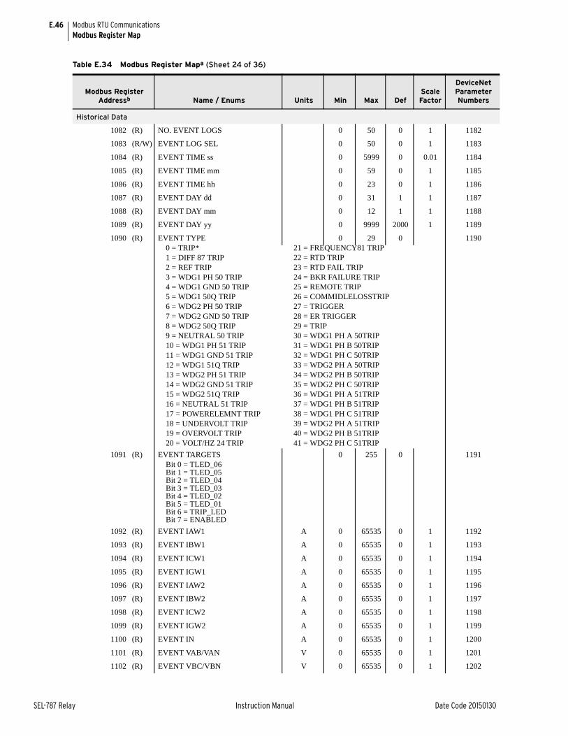
E.46
SEL-787 Relay Instruction Manual Date Code 20150130
Modbus RTU CommunicationsModbus Register Map
Historical Data
1082 (R) NO. EVENT LOGS 0 50 0 1 1182
1083 (R/W) EVENT LOG SEL 0 50 0 1 1183
1084 (R) EVENT TIME ss 0 5999 0 0.01 1184
1085 (R) EVENT TIME mm 0 59 0 1 1185
1086 (R) EVENT TIME hh 0 23 0 1 1186
1087 (R) EVENT DAY dd 0 31 1 1 1187
1088 (R) EVENT DAY mm 0 12 1 1 1188
1089 (R) EVENT DAY yy 0 9999 2000 1 1189
1090 (R) EVENT TYPE 0 29 0 11900 = TRIP*1 = DIFF 87 TRIP2 = REF TRIP3 = WDG1 PH 50 TRIP4 = WDG1 GND 50 TRIP5 = WDG1 50Q TRIP6 = WDG2 PH 50 TRIP7 = WDG2 GND 50 TRIP8 = WDG2 50Q TRIP9 = NEUTRAL 50 TRIP10 = WDG1 PH 51 TRIP11 = WDG1 GND 51 TRIP12 = WDG1 51Q TRIP13 = WDG2 PH 51 TRIP14 = WDG2 GND 51 TRIP15 = WDG2 51Q TRIP16 = NEUTRAL 51 TRIP17 = POWERELEMNT TRIP18 = UNDERVOLT TRIP19 = OVERVOLT TRIP20 = VOLT/HZ 24 TRIP
21 = FREQUENCY81 TRIP22 = RTD TRIP23 = RTD FAIL TRIP24 = BKR FAILURE TRIP25 = REMOTE TRIP26 = COMMIDLELOSSTRIP27 = TRIGGER28 = ER TRIGGER29 = TRIP30 = WDG1 PH A 50TRIP 31 = WDG1 PH B 50TRIP 32 = WDG1 PH C 50TRIP 33 = WDG2 PH A 50TRIP 34 = WDG2 PH B 50TRIP 35 = WDG2 PH C 50TRIP 36 = WDG1 PH A 51TRIP 37 = WDG1 PH B 51TRIP 38 = WDG1 PH C 51TRIP 39 = WDG2 PH A 51TRIP 40 = WDG2 PH B 51TRIP 41 = WDG2 PH C 51TRIP
1091 (R) EVENT TARGETS 0 255 0 1191Bit 0 = TLED_06Bit 1 = TLED_05Bit 2 = TLED_04Bit 3 = TLED_03Bit 4 = TLED_02Bit 5 = TLED_01Bit 6 = TRIP_LEDBit 7 = ENABLED
1092 (R) EVENT IAW1 A 0 65535 0 1 1192
1093 (R) EVENT IBW1 A 0 65535 0 1 1193
1094 (R) EVENT ICW1 A 0 65535 0 1 1194
1095 (R) EVENT IGW1 A 0 65535 0 1 1195
1096 (R) EVENT IAW2 A 0 65535 0 1 1196
1097 (R) EVENT IBW2 A 0 65535 0 1 1197
1098 (R) EVENT ICW2 A 0 65535 0 1 1198
1099 (R) EVENT IGW2 A 0 65535 0 1 1199
1100 (R) EVENT IN A 0 65535 0 1 1200
1101 (R) EVENT VAB/VAN V 0 65535 0 1 1201
1102 (R) EVENT VBC/VBN V 0 65535 0 1 1202
Table E.34 Modbus Register Mapa (Sheet 24 of 36)
Modbus Register Addressb Name / Enums Units Min Max Def
Scale Factor
DeviceNet Parameter Numbers
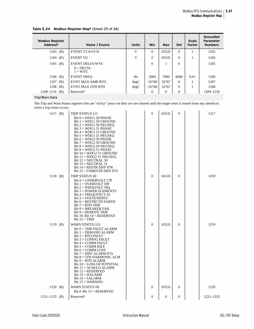
E.47
Date Code 20150130 Instruction Manual SEL-787 Relay
Modbus RTU CommunicationsModbus Register Map
1103 (R) EVENT VCA/VCN V 0 65535 0 1 1203
1104 (R) EVENT VG V 0 65535 0 1 1204
1105 (R) EVENT DELTA/WYE 0 1 0 12050 = DELTA1 = WYE
1106 (R) EVENT FREQ Hz 2000 7000 6000 0.01 1206
1107 (R) EVNT MAX AMB RTD degC -32768 32767 0 1 1207
1108 (R) EVNT MAX OTH RTD degC -32768 32767 0 1 1208
1109–1116 (R) Reservedc 0 0 0 1209–1216
Trip/Warn Data
The Trip and Warn Status registers bits are “sticky” (once set they are not cleared until the target reset is issued from any interface) when a trip event occurs.
1117 (R) TRIP STATUS LO 0 65535 0 1217Bit 0 = WDG1 50 PHASEBit 1 = WDG1 50 GROUNDBit 2 = WDG1 50 NEGSEQBit 3 = WDG1 51 PHASEBit 4 = WDG1 51 GROUNDBit 5 = WDG1 51 NEGSEQBit 6 = WDG2 50 PHASEBit 7 = WDG2 50 GROUNDBit 8 = WDG2 50 NEGSEQBit 9 = WDG2 51 PHASEBit 10 = WDG2 51 GROUNDBit 11 = WDG2 51 NEGSEQBit 12 = NEUTRAL 50Bit 13 = NEUTRAL 51Bit 14 = RESTR DIFF 87RBit 15 = UNRESTR DIFF 87U
1118 (R) TRIP STATUS HI 0 65535 0 1218Bit 0 = UNDERVOLT 27PBit 1 = OVERVOLT 59PBit 2 = NSEQVOLT 59QBit 3 = POWER ELEMENTSBit 4 = FREQUENCY 81Bit 5 = VOLTS/HERTZBit 6 = RESTRCTD EARTHBit 7 = RTD TRIPBit 8 = BREAKER FAILBit 9 = REMOTE TRIPBit 10–Bit 14 = RESERVEDBit 15 = TRIP
1119 (R) WARN STATUS LO 0 65535 0 1219Bit 0 = THR FAULT ALARMBit 1 = DEMAND ALARMBit 2 = RTD FAULTBit 3 = CONFIG FAULTBit 4 = COMM FAULTBit 5 = COMM IDLEBit 6 = COMM LOSSBit 7 = DIFF ALARM 87ABit 8 = 5TH HARMONIC ALMBit 9 = RTD ALARMBit 10 = LOSS OF POTNTIALBit 11 = AI HI/LO ALARMBit 12 = RESERVEDBit 13 = HALARMBit 14 = SALARMBit 15 = WARNING
1120 (R) WARN STATUS HI 0 65535 0 1220Bit 0–Bit 15 = RESERVED
1121–1125 (R) Reservedc 0 0 0 1221–1225
Table E.34 Modbus Register Mapa (Sheet 25 of 36)
Modbus Register Addressb Name / Enums Units Min Max Def
Scale Factor
DeviceNet Parameter Numbers
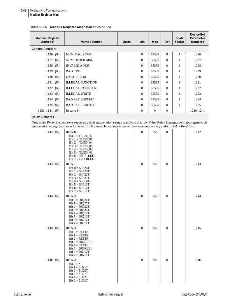
E.48
SEL-787 Relay Instruction Manual Date Code 20150130
Modbus RTU CommunicationsModbus Register Map
Commn Counters
1126 (R) NUM MSG RCVD 0 65535 0 1 1226
1127 (R) NUM OTHER MSG 0 65535 0 1 1227
1128 (R) INVALID ADDR 0 65535 0 1 1228
1129 (R) BAD CRC 0 65535 0 1 1229
1130 (R) UART ERROR 0 65535 0 1 1230
1131 (R) ILLEGAL FUNCTION 0 65535 0 1 1231
1132 (R) ILLEGAL REGISTER 0 65535 0 1 1232
1133 (R) ILLEGAL WRITE 0 65535 0 1 1233
1134 (R) BAD PKT FORMAT 0 65535 0 1 1234
1135 (R) BAD PKT LENGTH 0 65535 0 1 1235
1136–1141 (R) Reservedc 0 0 0 1236–1241
Relay Elements
Only a few Relay Element rows report actual bit enumeration strings specific to that row. Other Relay Element rows report generic bit enumeration strings (as shown for ROW 10). For exact bit enumerations of these elements see Appendix J: Relay Word Bits.
1142 (R) ROW 0 0 255 0 1242Bit 0 = TLED_06Bit 1 = TLED_05Bit 2 = TLED_04Bit 3 = TLED_03Bit 4 = TLED_02Bit 5 = TLED_01Bit 6 = TRIP_LEDBit 7 = ENABLED
1143 (R) ROW 1 0 255 0 1243Bit 0 = 50P24TBit 1 = 50P23TBit 2 = 50P22TBit 3 = 50P21TBit 4 = 50P14TBit 5 = 50P13TBit 6 = 50P12TBit 7 = 50P11T
1144 (R) ROW 2 0 255 0 1244Bit 0 = 50Q22TBit 1 = 50Q21TBit 2 = 50G22TBit 3 = 50G21TBit 4 = 50Q12TBit 5 = 50Q11TBit 6 = 50G12TBit 7 = 50G11T
1145 (R) ROW 3 0 255 0 1245Bit 0 = REF1PBit 1 = REF1RBit 2 = REF1FBit 3 = 50GREF1Bit 4 = REF1EBit 5 = 50NREF1Bit 6 = 50N12TBit 7 = 50N11T
1146 (R) ROW 4 0 255 0 1246Bit 0 = *Bit 1 = 51N1TBit 2 = 51Q2TBit 3 = 51Q1TBit 4 = 51G2TBit 5 = 51G1T
Table E.34 Modbus Register Mapa (Sheet 26 of 36)
Modbus Register Addressb Name / Enums Units Min Max Def
Scale Factor
DeviceNet Parameter Numbers
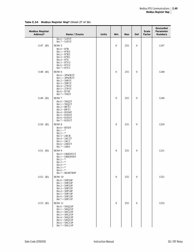
E.49
Date Code 20150130 Instruction Manual SEL-787 Relay
Modbus RTU CommunicationsModbus Register Map
Bit 6 = 51P2TBit 7 = 51P1T
1147 (R) ROW 5 0 255 0 1247Bit 0 = 87RBit 1 = 87R3Bit 2 = 87R2Bit 3 = 87R1Bit 4 = 87UBit 5 = 87U3Bit 6 = 87U2Bit 7 = 87U1
1148 (R) ROW 6 0 255 0 1248Bit 0 = 3PWR2TBit 1 = 3PWR1TBit 2 = 59P2TBit 3 = 59P1TBit 4 = 27P2TBit 5 = 27P1TBit 6 = 87ATBit 7 = TH5T
1149 (R) ROW 7 0 255 0 1249Bit 0 = 59Q2TBit 1 = 59Q1TBit 2 = BFT2Bit 3 = BFT1Bit 4 = 81D4TBit 5 = 81D3TBit 6 = 81D2TBit 7 = 81D1T
1150 (R) ROW 8 0 255 0 1250Bit 0 = RTDTBit 1 = *Bit 2 = *Bit 3 = 24CRBit 4 = 24C2TBit 5 = 24C2Bit 6 = 24D1TBit 7 = 24D1
1151 (R) ROW 9 0 255 0 1251Bit 0 = ORED51TBit 1 = ORED50TBit 2 = *Bit 3 = *Bit 4 = *Bit 5 = *Bit 6 = *Bit 7 = REMTRIP
1152 (R) ROW 10 0 255 0 1252Bit 0 = 50P24PBit 1 = 50P23PBit 2 = 50P22PBit 3 = 50P21PBit 4 = 50P14PBit 5 = 50P13PBit 6 = 50P12PBit 7 = 50P11P
1153 (R) ROW 11 0 255 0 1253Bit 0 = 50Q22PBit 1 = 50Q21PBit 2 = 50G22PBit 3 = 50G21PBit 4 = 50Q12PBit 5 = 50Q11PBit 6 = 50G12PBit 7 = 50G11P
Table E.34 Modbus Register Mapa (Sheet 27 of 36)
Modbus Register Addressb Name / Enums Units Min Max Def
Scale Factor
DeviceNet Parameter Numbers
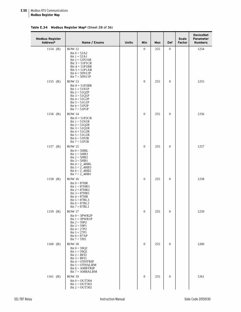
E.50
SEL-787 Relay Instruction Manual Date Code 20150130
Modbus RTU CommunicationsModbus Register Map
1154 (R) ROW 12 0 255 0 1254Bit 0 = 52A2Bit 1 = 52A1Bit 2 = 51P2ARBit 3 = 51P1CRBit 4 = 51P1BRBit 5 = 51P1ARBit 6 = 50N12PBit 7 = 50N11P
1155 (R) ROW 13 0 255 0 1255Bit 0 = 51P2BRBit 1 = 51N1PBit 2 = 51Q2PBit 3 = 51Q1PBit 4 = 51G2PBit 5 = 51G1PBit 6 = 51P2PBit 7 = 51P1P
1156 (R) ROW 14 0 255 0 1256Bit 0 = 51P2CRBit 1 = 51N1RBit 2 = 51Q2RBit 3 = 51Q1RBit 4 = 51G2RBit 5 = 51G1RBit 6 = 51P2RBit 7 = 51P1R
1157 (R) ROW 15 0 255 0 1257Bit 0 = 5HBLBit 1 = 5HB3Bit 2 = 5HB2Bit 3 = 5HB1Bit 4 = 2_4HBLBit 5 = 2_4HB3Bit 6 = 2_4HB2Bit 7 = 2_4HB1
1158 (R) ROW 16 0 255 0 1258Bit 0 = 87HRBit 1 = 87HR3Bit 2 = 87HR2Bit 3 = 87HR1Bit 4 = 87HBBit 5 = 87BL3Bit 6 = 87BL2Bit 7 = 87BL1
1159 (R) ROW 17 0 255 0 1259Bit 0 = 3PWR2PBit 1 = 3PWR1PBit 2 = 59P2Bit 3 = 59P1Bit 4 = 27P2Bit 5 = 27P1Bit 6 = 87APBit 7 = TH5
1160 (R) ROW 18 0 255 0 1260Bit 0 = 59Q2Bit 1 = 59Q1Bit 2 = BFI2Bit 3 = BFI1Bit 4 = OTHTRIPBit 5 = OTHALRMBit 6 = AMBTRIPBit 7 = AMBALRM
1161 (R) ROW 19 0 255 0 1261Bit 0 = OUT304Bit 1 = OUT303Bit 2 = OUT302
Table E.34 Modbus Register Mapa (Sheet 28 of 36)
Modbus Register Addressb Name / Enums Units Min Max Def
Scale Factor
DeviceNet Parameter Numbers
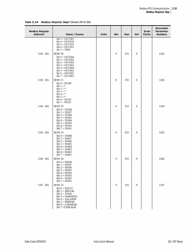
E.51
Date Code 20150130 Instruction Manual SEL-787 Relay
Modbus RTU CommunicationsModbus Register Map
Bit 3 = OUT301Bit 4 = OUT103Bit 5 = OUT102Bit 6 = OUT101Bit 7 = TRIP
1162 (R) ROW 20 0 255 0 1262Bit 0 = OUT504Bit 1 = OUT503Bit 2 = OUT502Bit 3 = OUT501Bit 4 = OUT404Bit 5 = OUT403Bit 6 = OUT402Bit 7 = OUT401
1163 (R) ROW 21 0 255 0 1263Bit 0 = IN108Bit 1 = *Bit 2 = *Bit 3 = *Bit 4 = *Bit 5 = *Bit 6 = IN102Bit 7 = IN101
1164 (R) ROW 22 0 255 0 1264Bit 0 = IN308Bit 1 = IN307Bit 2 = IN306Bit 3 = IN305Bit 4 = IN304Bit 5 = IN303Bit 6 = IN302Bit 7 = IN301
1165 (R) ROW 23 0 255 0 1265Bit 0 = IN408Bit 1 = IN407Bit 2 = IN406Bit 3 = IN405Bit 4 = IN404Bit 5 = IN403Bit 6 = IN402Bit 7 = IN401
1166 (R) ROW 24 0 255 0 1266Bit 0 = IN508Bit 1 = IN507Bit 2 = IN506Bit 3 = IN505Bit 4 = IN504Bit 5 = IN503Bit 6 = IN502Bit 7 = IN501
1167 (R) ROW 25 0 255 0 1267Bit 0 = FAULT Bit 1 = IRIGOKBit 2 = TSOKBit 3 = WARNINGBit 4 = SALARMBit 5 = PMDOKBit 6 = LINKBOKBit 7 =LINKAOK
Table E.34 Modbus Register Mapa (Sheet 29 of 36)
Modbus Register Addressb Name / Enums Units Min Max Def
Scale Factor
DeviceNet Parameter Numbers
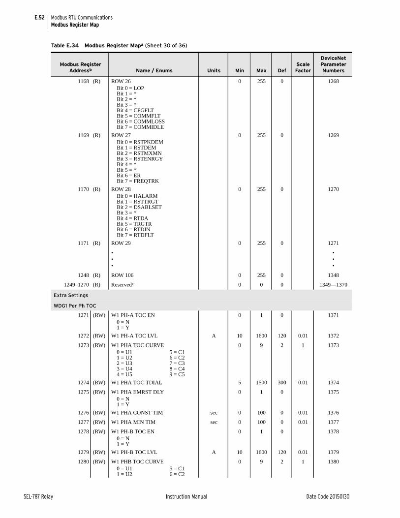
E.52
SEL-787 Relay Instruction Manual Date Code 20150130
Modbus RTU CommunicationsModbus Register Map
1168 (R) ROW 26 0 255 0 1268Bit 0 = LOPBit 1 = *Bit 2 = *Bit 3 = *Bit 4 = CFGFLTBit 5 = COMMFLTBit 6 = COMMLOSSBit 7 = COMMIDLE
1169 (R) ROW 27 0 255 0 1269Bit 0 = RSTPKDEMBit 1 = RSTDEMBit 2 = RSTMXMNBit 3 = RSTENRGYBit 4 = *Bit 5 = *Bit 6 = ERBit 7 = FREQTRK
1170 (R) ROW 28 0 255 0 1270Bit 0 = HALARMBit 1 = RSTTRGTBit 2 = DSABLSETBit 3 = *Bit 4 = RTDABit 5 = TRGTRBit 6 = RTDINBit 7 = RTDFLT
1171 (R) ROW 29 0 255 0 1271
•••
•••
1248 (R) ROW 106 0 255 0 1348
1249–1270 (R) Reservedc 0 0 0 1349—1370
Extra Settings
WDG1 Per Ph TOC
1271 (RW) W1 PH-A TOC EN 0 1 0 13710 = N1 = Y
1272 (RW) W1 PH-A TOC LVL A 10 1600 120 0.01 1372
1273 (RW) W1 PHA TOC CURVE 0 9 2 1 13730 = U1 5 = C11 = U2 6 = C22 = U3 7 = C33 = U4 8 = C44 = U5 9 = C5
1274 (RW) W1 PHA TOC TDIAL 5 1500 300 0.01 1374
1275 (RW) W1 PHA EMRST DLY 0 1 0 13750 = N1 = Y
1276 (RW) W1 PHA CONST TIM sec 0 100 0 0.01 1376
1277 (RW) W1 PHA MIN TIM sec 0 100 0 0.01 1377
1278 (RW) W1 PH-B TOC EN 0 1 0 13780 = N1 = Y
1279 (RW) W1 PH-B TOC LVL A 10 1600 120 0.01 1379
1280 (RW) W1 PHB TOC CURVE 0 9 2 1 13800 = U1 5 = C11 = U2 6 = C2
Table E.34 Modbus Register Mapa (Sheet 30 of 36)
Modbus Register Addressb Name / Enums Units Min Max Def
Scale Factor
DeviceNet Parameter Numbers
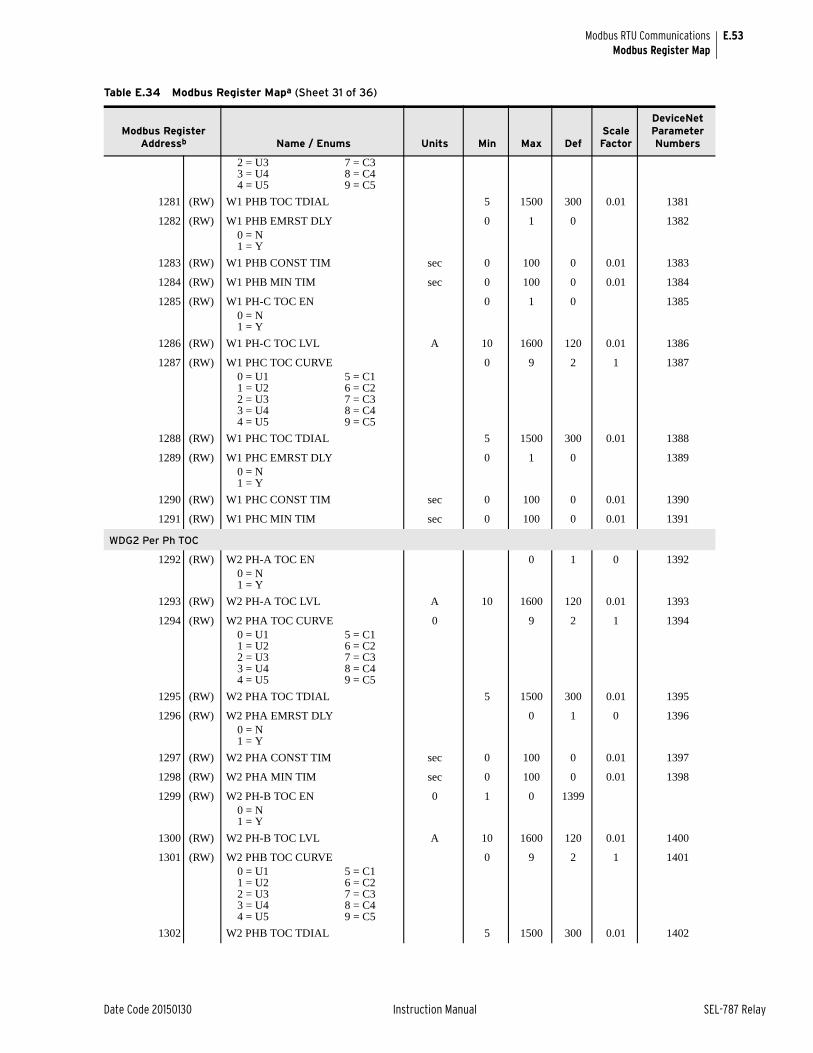
E.53
Date Code 20150130 Instruction Manual SEL-787 Relay
Modbus RTU CommunicationsModbus Register Map
2 = U3 7 = C33 = U4 8 = C44 = U5 9 = C5
1281 (RW) W1 PHB TOC TDIAL 5 1500 300 0.01 1381
1282 (RW) W1 PHB EMRST DLY 0 1 0 13820 = N1 = Y
1283 (RW) W1 PHB CONST TIM sec 0 100 0 0.01 1383
1284 (RW) W1 PHB MIN TIM sec 0 100 0 0.01 1384
1285 (RW) W1 PH-C TOC EN 0 1 0 13850 = N1 = Y
1286 (RW) W1 PH-C TOC LVL A 10 1600 120 0.01 1386
1287 (RW) W1 PHC TOC CURVE 0 9 2 1 13870 = U1 5 = C11 = U2 6 = C22 = U3 7 = C33 = U4 8 = C44 = U5 9 = C5
1288 (RW) W1 PHC TOC TDIAL 5 1500 300 0.01 1388
1289 (RW) W1 PHC EMRST DLY 0 1 0 13890 = N1 = Y
1290 (RW) W1 PHC CONST TIM sec 0 100 0 0.01 1390
1291 (RW) W1 PHC MIN TIM sec 0 100 0 0.01 1391
WDG2 Per Ph TOC
1292 (RW) W2 PH-A TOC EN 0 1 0 13920 = N1 = Y
1293 (RW) W2 PH-A TOC LVL A 10 1600 120 0.01 1393
1294 (RW) W2 PHA TOC CURVE 0 9 2 1 13940 = U1 5 = C11 = U2 6 = C22 = U3 7 = C33 = U4 8 = C44 = U5 9 = C5
1295 (RW) W2 PHA TOC TDIAL 5 1500 300 0.01 1395
1296 (RW) W2 PHA EMRST DLY 0 1 0 1396 0 = N1 = Y
1297 (RW) W2 PHA CONST TIM sec 0 100 0 0.01 1397
1298 (RW) W2 PHA MIN TIM sec 0 100 0 0.01 1398
1299 (RW) W2 PH-B TOC EN 0 1 0 13990 = N1 = Y
1300 (RW) W2 PH-B TOC LVL A 10 1600 120 0.01 1400
1301 (RW) W2 PHB TOC CURVE 0 9 2 1 14010 = U1 5 = C11 = U2 6 = C22 = U3 7 = C33 = U4 8 = C44 = U5 9 = C5
1302 W2 PHB TOC TDIAL 5 1500 300 0.01 1402
Table E.34 Modbus Register Mapa (Sheet 31 of 36)
Modbus Register Addressb Name / Enums Units Min Max Def
Scale Factor
DeviceNet Parameter Numbers
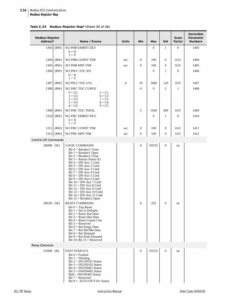
E.54
SEL-787 Relay Instruction Manual Date Code 20150130
Modbus RTU CommunicationsModbus Register Map
1303 (RW) W2 PHB EMRST DLY 0 1 0 14030 = N1 = Y
1304 (RW) W2 PHB CONST TIM sec 0 100 0 0.01 1404
1305 (RW) W2 PHB MIN TIM sec 0 100 0 0.01 1405
1306 (RW) W2 PH-C TOC EN 0 1 0 14060 = N1 = Y
1307 (RW) W2 PH-C TOC LVL A 10 1600 120 0.01 1407
1308 (RW) W2 PHC TOC CURVE 0 9 2 1 14080 = U1 5 = C11 = U2 6 = C22 = U3 7 = C33 = U4 8 = C44 = U5 9 = C5
1309 (RW) W2 PHC TOC TDIAL 5 1500 300 0.01 1409
1310 (RW) W2 PHC EMRST DLY 0 1 0 14100 = N1 = Y
1311 (RW) W2 PHC CONST TIM sec 0 100 0 0.01 1411
1312 (RW) W2 PHC MIN TIM sec 0 100 0 0.01 1412
Control I/O Commands
2000H (W) LOGIC COMMAND 0 65535 0 naBit 0 = Breaker1 CloseBit 1 = Breaker1 OpenBit 2 = Breaker2 CloseBit 3 = Return Status 0/1Bit 4 = DN Aux 1 CmdBit 5 = DN Aux 2 CmdBit 6 = DN Aux 3 CmdBit 7 = DN Aux 4 CmdBit 8 = DN Aux 5 CmdBit 9 = DN Aux 6 CmdBit 10 = DN Aux 7 CmdBit 11 = DN Aux 8 CmdBit 12 = DN Aux 9 CmdBit 13 = DN Aux 10 CmdBit 14 = DN Aux 11 CmdBit 15 = Breaker2 Open
2001H (W) RESET COMMAND 0 255 0 naBit 0 = Trip ResetBit 1 = Set to DefaultsBit 2 = Reset Stat DataBit 3 = Reset Hist DataBit 4 = Reset Comm CntrBit 5 = ReservedBit 6 = Rst Enrgy DataBit 7 = Rst Mx/Mn DataBit 8 = Rst DemandBit 9 = Rst Peak DemandBit 10–Bit 15 = Reserved
Relay Elements
2100H (R) FAST STATUS 0 0 65535 0 naBit 0 = FaultedBit 1 = WarningBit 2 = IN1/IN101 StatusBit 3 = IN2/IN102 StatusBit 4 = IN3/IN401 StatusBit 5 = IN4/IN402 StatusBit6 = IN5/IN403 StatusBit 7 = ReservedBit 8 = AUX1/OUT101 Status
Table E.34 Modbus Register Mapa (Sheet 32 of 36)
Modbus Register Addressb Name / Enums Units Min Max Def
Scale Factor
DeviceNet Parameter Numbers
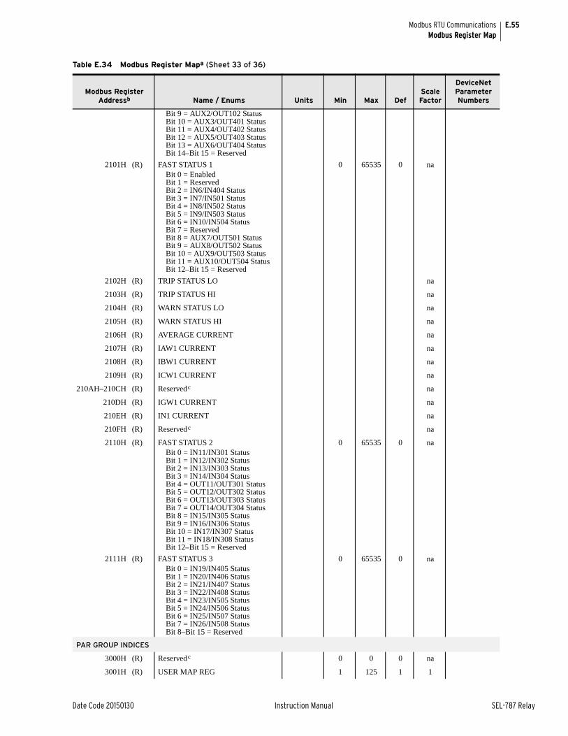
E.55
Date Code 20150130 Instruction Manual SEL-787 Relay
Modbus RTU CommunicationsModbus Register Map
Bit 9 = AUX2/OUT102 StatusBit 10 = AUX3/OUT401 StatusBit 11 = AUX4/OUT402 StatusBit 12 = AUX5/OUT403 StatusBit 13 = AUX6/OUT404 StatusBit 14–Bit 15 = Reserved
2101H (R) FAST STATUS 1 0 65535 0 naBit 0 = EnabledBit 1 = ReservedBit 2 = IN6/IN404 StatusBit 3 = IN7/IN501 StatusBit 4 = IN8/IN502 StatusBit 5 = IN9/IN503 StatusBit 6 = IN10/IN504 StatusBit 7 = ReservedBit 8 = AUX7/OUT501 StatusBit 9 = AUX8/OUT502 StatusBit 10 = AUX9/OUT503 StatusBit 11 = AUX10/OUT504 StatusBit 12–Bit 15 = Reserved
2102H (R) TRIP STATUS LO na
2103H (R) TRIP STATUS HI na
2104H (R) WARN STATUS LO na
2105H (R) WARN STATUS HI na
2106H (R) AVERAGE CURRENT na
2107H (R) IAW1 CURRENT na
2108H (R) IBW1 CURRENT na
2109H (R) ICW1 CURRENT na
210AH–210CH (R) Reservedc na
210DH (R) IGW1 CURRENT na
210EH (R) IN1 CURRENT na
210FH (R) Reservedc na
2110H (R) FAST STATUS 2 0 65535 0 naBit 0 = IN11/IN301 StatusBit 1 = IN12/IN302 StatusBit 2 = IN13/IN303 StatusBit 3 = IN14/IN304 StatusBit 4 = OUT11/OUT301 StatusBit 5 = OUT12/OUT302 StatusBit 6 = OUT13/OUT303 StatusBit 7 = OUT14/OUT304 StatusBit 8 = IN15/IN305 StatusBit 9 = IN16/IN306 StatusBit 10 = IN17/IN307 StatusBit 11 = IN18/IN308 StatusBit 12–Bit 15 = Reserved
2111H (R) FAST STATUS 3 0 65535 0 naBit 0 = IN19/IN405 StatusBit 1 = IN20/IN406 StatusBit 2 = IN21/IN407 StatusBit 3 = IN22/IN408 StatusBit 4 = IN23/IN505 StatusBit 5 = IN24/IN506 StatusBit 6 = IN25/IN507 StatusBit 7 = IN26/IN508 StatusBit 8–Bit 15 = Reserved
PAR GROUP INDICES
3000H (R) Reservedc 0 0 0 na
3001H (R) USER MAP REG 1 125 1 1
Table E.34 Modbus Register Mapa (Sheet 33 of 36)
Modbus Register Addressb Name / Enums Units Min Max Def
Scale Factor
DeviceNet Parameter Numbers
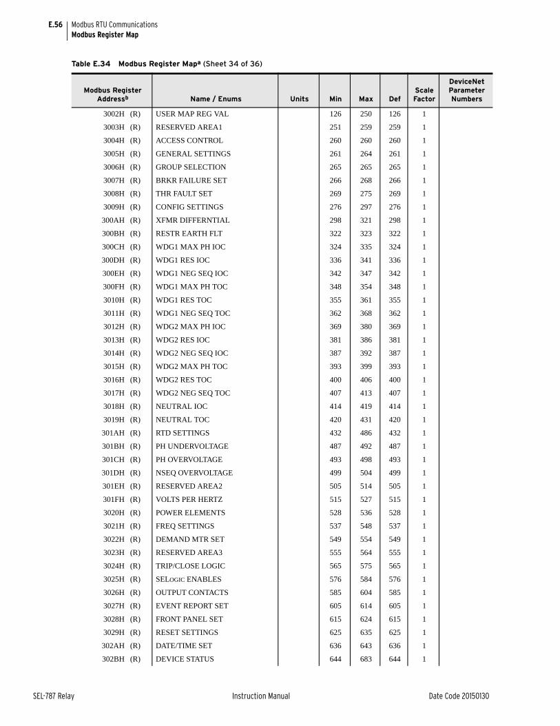
E.56
SEL-787 Relay Instruction Manual Date Code 20150130
Modbus RTU CommunicationsModbus Register Map
3002H (R) USER MAP REG VAL 126 250 126 1
3003H (R) RESERVED AREA1 251 259 259 1
3004H (R) ACCESS CONTROL 260 260 260 1
3005H (R) GENERAL SETTINGS 261 264 261 1
3006H (R) GROUP SELECTION 265 265 265 1
3007H (R) BRKR FAILURE SET 266 268 266 1
3008H (R) THR FAULT SET 269 275 269 1
3009H (R) CONFIG SETTINGS 276 297 276 1
300AH (R) XFMR DIFFERNTIAL 298 321 298 1
300BH (R) RESTR EARTH FLT 322 323 322 1
300CH (R) WDG1 MAX PH IOC 324 335 324 1
300DH (R) WDG1 RES IOC 336 341 336 1
300EH (R) WDG1 NEG SEQ IOC 342 347 342 1
300FH (R) WDG1 MAX PH TOC 348 354 348 1
3010H (R) WDG1 RES TOC 355 361 355 1
3011H (R) WDG1 NEG SEQ TOC 362 368 362 1
3012H (R) WDG2 MAX PH IOC 369 380 369 1
3013H (R) WDG2 RES IOC 381 386 381 1
3014H (R) WDG2 NEG SEQ IOC 387 392 387 1
3015H (R) WDG2 MAX PH TOC 393 399 393 1
3016H (R) WDG2 RES TOC 400 406 400 1
3017H (R) WDG2 NEG SEQ TOC 407 413 407 1
3018H (R) NEUTRAL IOC 414 419 414 1
3019H (R) NEUTRAL TOC 420 431 420 1
301AH (R) RTD SETTINGS 432 486 432 1
301BH (R) PH UNDERVOLTAGE 487 492 487 1
301CH (R) PH OVERVOLTAGE 493 498 493 1
301DH (R) NSEQ OVERVOLTAGE 499 504 499 1
301EH (R) RESERVED AREA2 505 514 505 1
301FH (R) VOLTS PER HERTZ 515 527 515 1
3020H (R) POWER ELEMENTS 528 536 528 1
3021H (R) FREQ SETTINGS 537 548 537 1
3022H (R) DEMAND MTR SET 549 554 549 1
3023H (R) RESERVED AREA3 555 564 555 1
3024H (R) TRIP/CLOSE LOGIC 565 575 565 1
3025H (R) SELOGIC ENABLES 576 584 576 1
3026H (R) OUTPUT CONTACTS 585 604 585 1
3027H (R) EVENT REPORT SET 605 614 605 1
3028H (R) FRONT PANEL SET 615 624 615 1
3029H (R) RESET SETTINGS 625 635 625 1
302AH (R) DATE/TIME SET 636 643 636 1
302BH (R) DEVICE STATUS 644 683 644 1
Table E.34 Modbus Register Mapa (Sheet 34 of 36)
Modbus Register Addressb Name / Enums Units Min Max Def
Scale Factor
DeviceNet Parameter Numbers
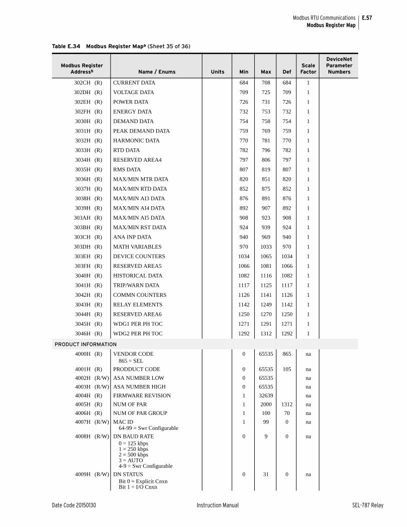
E.57
Date Code 20150130 Instruction Manual SEL-787 Relay
Modbus RTU CommunicationsModbus Register Map
302CH (R) CURRENT DATA 684 708 684 1
302DH (R) VOLTAGE DATA 709 725 709 1
302EH (R) POWER DATA 726 731 726 1
302FH (R) ENERGY DATA 732 753 732 1
3030H (R) DEMAND DATA 754 758 754 1
3031H (R) PEAK DEMAND DATA 759 769 759 1
3032H (R) HARMONIC DATA 770 781 770 1
3033H (R) RTD DATA 782 796 782 1
3034H (R) RESERVED AREA4 797 806 797 1
3035H (R) RMS DATA 807 819 807 1
3036H (R) MAX/MIN MTR DATA 820 851 820 1
3037H (R) MAX/MIN RTD DATA 852 875 852 1
3038H (R) MAX/MIN AI3 DATA 876 891 876 1
3039H (R) MAX/MIN AI4 DATA 892 907 892 1
303AH (R) MAX/MIN AI5 DATA 908 923 908 1
303BH (R) MAX/MIN RST DATA 924 939 924 1
303CH (R) ANA INP DATA 940 969 940 1
303DH (R) MATH VARIABLES 970 1033 970 1
303EH (R) DEVICE COUNTERS 1034 1065 1034 1
303FH (R) RESERVED AREA5 1066 1081 1066 1
3040H (R) HISTORICAL DATA 1082 1116 1082 1
3041H (R) TRIP/WARN DATA 1117 1125 1117 1
3042H (R) COMMN COUNTERS 1126 1141 1126 1
3043H (R) RELAY ELEMENTS 1142 1249 1142 1
3044H (R) RESERVED AREA6 1250 1270 1250 1
3045H (R) WDG1 PER PH TOC 1271 1291 1271 1
3046H (R) WDG2 PER PH TOC 1292 1312 1292 1
PRODUCT INFORMATION
4000H (R) VENDOR CODE 0 65535 865 na865 = SEL
4001H (R) PRODDUCT CODE 0 65535 105 na
4002H (R/W) ASA NUMBER LOW 0 65535 na
4003H (R/W) ASA NUMBER HIGH 0 65535 na
4004H (R) FIRMWARE REVISION 1 32639 na
4005H (R) NUM OF PAR 1 2000 1312 na
4006H (R) NUM OF PAR GROUP 1 100 70 na
4007H (R/W) MAC ID 1 99 0 na64-99 = Swr Configurable
4008H (R/W) DN BAUD RATE 0 9 0 na0 = 125 kbps1 = 250 kbps2 = 500 kbps3 = AUTO4-9 = Swr Configurable
4009H (R/W) DN STATUS 0 31 0 naBit 0 = Explicit CnxnBit 1 = I/O Cnxn
Table E.34 Modbus Register Mapa (Sheet 35 of 36)
Modbus Register Addressb Name / Enums Units Min Max Def
Scale Factor
DeviceNet Parameter Numbers
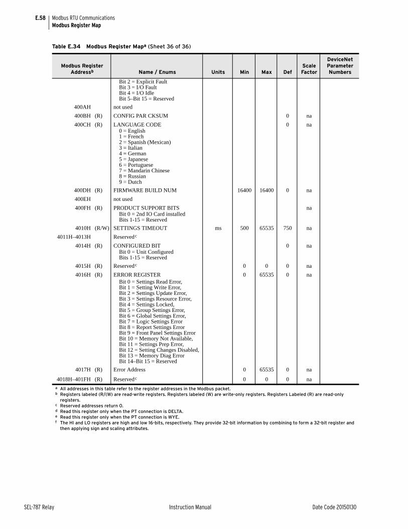
E.58
SEL-787 Relay Instruction Manual Date Code 20150130
Modbus RTU CommunicationsModbus Register Map
Bit 2 = Explicit FaultBit 3 = I/O FaultBit 4 = I/O IdleBit 5–Bit 15 = Reserved
400AH not used
400BH (R) CONFIG PAR CKSUM 0 na
400CH (R) LANGUAGE CODE 0 na0 = English1 = French2 = Spanish (Mexican)3 = Italian4 = German5 = Japanese6 = Portuguese7 = Mandarin Chinese8 = Russian9 = Dutch
400DH (R) FIRMWARE BUILD NUM 16400 16400 0 na
400EH not used
400FH (R) PRODUCT SUPPORT BITS naBit 0 = 2nd IO Card installedBits 1-15 = Reserved
4010H (R/W) SETTINGS TIMEOUT ms 500 65535 750 na
4011H–4013H Reservedc
4014H (R) CONFIGURED BIT 0 naBit 0 = Unit ConfiguredBits 1-15 = Reserved
4015H (R) Reservedc 0 0 0 na
4016H (R) ERROR REGISTER 0 65535 0 naBit 0 = Settings Read Error,Bit 1 = Setting Write Error,Bit 2 = Settings Update Error,Bit 3 = Settings Resource Error,Bit 4 = Settings Locked,Bit 5 = Group Settings Error,Bit 6 = Global Settings Error,Bit 7 = Logic Settings ErrorBit 8 = Report Settings ErrorBit 9 = Front Panel Settings ErrorBit 10 = Memory Not Available,Bit 11 = Settings Prep Error,Bit 12 = Setting Changes Disabled,Bit 13 = Memory Diag ErrorBit 14–Bit 15 = Reserved
4017H (R) Error Address 0 65535 0 na
4018H–401FH (R) Reservedc 0 0 0 na
a All addresses in this table refer to the register addresses in the Modbus packet.b Registers labeled (R/(W) are read-write registers. Registers labeled (W) are write-only registers. Registers Labeled (R) are read-only
registers.c Reserved addresses return 0.d Read this register only when the PT connection is DELTA.e Read this register only when the PT connection is WYE.f The HI and LO registers are high and low 16-bits, respectively. They provide 32-bit information by combining to form a 32-bit register and
then applying sign and scaling attributes.
Table E.34 Modbus Register Mapa (Sheet 36 of 36)
Modbus Register Addressb Name / Enums Units Min Max Def
Scale Factor
DeviceNet Parameter Numbers
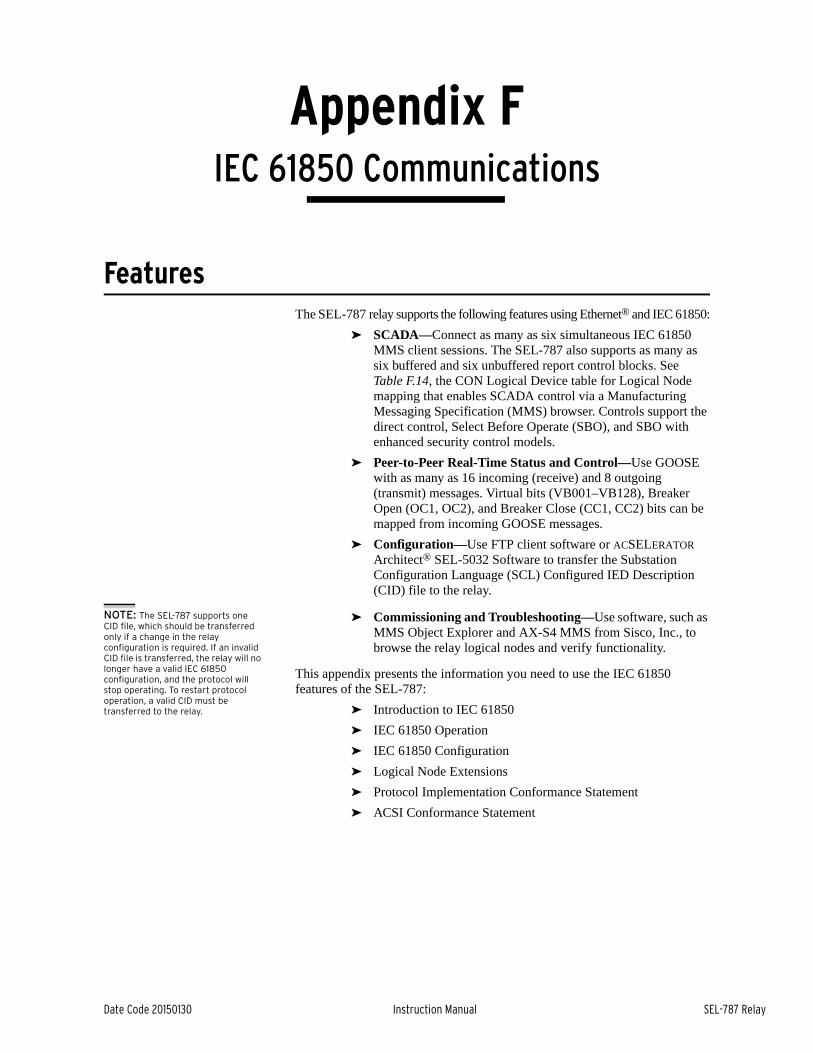
Date Code 20150130 Instruction Manual SEL-787 Relay
Appendix FIEC 61850 Communications
Instruction Manual
FeaturesThe SEL-787 relay supports the following features using Ethernet® and IEC 61850:
➤ SCADA—Connect as many as six simultaneous IEC 61850 MMS client sessions. The SEL-787 also supports as many as six buffered and six unbuffered report control blocks. See Table F.14, the CON Logical Device table for Logical Node mapping that enables SCADA control via a Manufacturing Messaging Specification (MMS) browser. Controls support the direct control, Select Before Operate (SBO), and SBO with enhanced security control models.
➤ Peer-to-Peer Real-Time Status and Control—Use GOOSE with as many as 16 incoming (receive) and 8 outgoing (transmit) messages. Virtual bits (VB001–VB128), Breaker Open (OC1, OC2), and Breaker Close (CC1, CC2) bits can be mapped from incoming GOOSE messages.
➤ Configuration—Use FTP client software or ACSELERATOR Architect® SEL-5032 Software to transfer the Substation Configuration Language (SCL) Configured IED Description (CID) file to the relay.
NOTE: The SEL-787 supports one CID file, which should be transferred only if a change in the relay configuration is required. If an invalid CID file is transferred, the relay will no longer have a valid IEC 61850 configuration, and the protocol will stop operating. To restart protocol operation, a valid CID must be transferred to the relay.
➤ Commissioning and Troubleshooting—Use software, such as MMS Object Explorer and AX-S4 MMS from Sisco, Inc., to browse the relay logical nodes and verify functionality.
This appendix presents the information you need to use the IEC 61850 features of the SEL-787:
➤ Introduction to IEC 61850
➤ IEC 61850 Operation
➤ IEC 61850 Configuration
➤ Logical Node Extensions
➤ Protocol Implementation Conformance Statement
➤ ACSI Conformance Statement
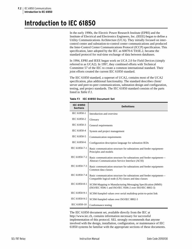
F.2
SEL-787 Relay Instruction Manual Date Code 20150130
IEC 61850 CommunicationsIntroduction to IEC 61850
Introduction to IEC 61850In the early 1990s, the Electric Power Research Institute (EPRI) and the Institute of Electrical and Electronics Engineers, Inc. (IEEE) began to define a Utility Communications Architecture (UCA). They initially focused on inter-control center and substation-to-control center communications and produced the Inter-Control Center Communications Protocol (ICCP) specification. This specification, later adopted by the IEC as 60870-6 TASE.2, became the standard protocol for real-time exchange of data between databases.
In 1994, EPRI and IEEE began work on UCA 2.0 for Field Devices (simply referred to as UCA2). In 1997, they combined efforts with Technical Committee 57 of the IEC to create a common international standard. Their joint efforts created the current IEC 61850 standard.
The IEC 61850 standard, a superset of UCA2, contains most of the UCA2 specification, plus additional functionality. The standard describes client/server and peer-to-peer communications, substation design and configuration, testing, and project standards. The IEC 61850 standard consists of the parts listed in Table F.1.
The IEC 61850 document set, available directly from the IEC at http://www.iec.ch, contains information necessary for successful implementation of this protocol. SEL strongly recommends that anyone involved with the design, installation, configuration, or maintenance of IEC 61850 systems be familiar with the appropriate sections of these documents.
Table F.1 IEC 61850 Document Set
IEC 61850 Sections
Definitions
IEC 61850-1 Introduction and overview
IEC 61850-2 Glossary
IEC 61850-3 General requirements
IEC 61850-4 System and project management
IEC 61850-5 Communication requirements
IEC 61850-6 Configuration description language for substation IEDs
IEC 61850-7-1 Basic communication structure for substations and feeder equipment-Principles and models
IEC 61850-7-2 Basic communication structure for substations and feeder equipment—Abstract Communication Service Interface (ACSI)
IEC 61850-7-3 Basic communication structure for substations and feeder equipment-Common data classes
IEC 61850-7-4 Basic communication structure for substations and feeder equipment—Compatible logical node (LN) classes and data classes
IEC 61850-8-1 SCSM-Mapping to Manufacturing Messaging Specification (MMS) (ISO/IEC 9506-1 and ISO/IEC 9506-2 over ISO/IEC 8802-3)
IEC 61850-9-1 SCSM-Sampled values over serial multidrop point-to-point link
IEC 61850-9-2 SCSM-Sampled values over ISO/IEC 8802-3
IEC 61850-10 Conformance testing
F.3
Date Code 20150130 Instruction Manual SEL-787 Relay
IEC 61850 CommunicationsIEC 61850 Operation
IEC 61850 OperationEthernet Networking IEC 61850 and Ethernet networking are available as options in the SEL-787.
In addition to IEC 61850, the Ethernet port provides support protocols and data exchange, including FTP and Telnet. Access the SEL-787 Port 1 settings to configure all of the Ethernet settings, including IEC 61850 enable settings.
The SEL Ethernet port supports IEC 61850 services, including transport of Logical Node objects, over TCP/IP. The Ethernet port can coordinate a maximum of six concurrent IEC 61850 sessions.
Object Models The IEC 61850 standard relies heavily on the Abstract Communication Service Interface (ACSI) model to define a set of service and the responses to those services. In terms of network behavior, abstract modeling enables all IEDs to act identically. These abstract models are used to create objects (data items) and services that exist independently of any underlying protocols. These objects are in conformance with the common data class (CDC) specification IEC 61850-7-3, which describes the type and structure of each element within a logical node. CDCs for status, measurements, controllable analogs and statuses, and settings all have unique CDC attributes. Each CDC attribute belongs to a set of functional constraints that groups the attributes into specific categories such as status (ST), description (DC), and substituted value (SV). Functional constraints, CDCs and CDC attributes are used as building blocks for defining Local Nodes.
UCA2 uses GOMSFE (Generic Object Models for Substation and Feeder Equipment) to present data from station IEDs as a series of objects called models or bricks. The IEC working group has incorporated GOMSFE concepts into the standard, with some modifications to terminology; one change was the renaming of bricks to logical nodes. Each logical node represents a group of data (controls, status, measurements, etc.) associated with a particular function. For example, the MMXU logical node (polyphase measurement unit) contains measurement data and other points associated with three-phase metering including voltages and currents. Each IED may contain many functions such as protection, metering, and control. Multiple logical nodes represent the functions in multifunction devices.
Logical nodes can be organized into logical devices that are similar to directories on a computer disk. As represented in the IEC 61850 network, each physical device can contain many logical devices, and each logical device can contain many logical nodes. Many relays, meters, and other IEC 61850 devices contain one primary logical device where all models are organized.
IEC 61850 devices are capable of self-description. You do not need to refer to the specifications for the logical nodes, measurements, and other components to request data from another IEC 61850 device. IEC 61850 clients can request and display a list and description of the data available in an IEC 61850 server device. This process is similar to the autoconfiguration process used within SEL communications processors (SEL-2032 and SEL-2030). Simply run an MMS browser to query devices on an IEC 61850 network and discover what data are available. Self-description also permits extensions to both standard and custom data models. Instead of having to look up data in a profile stored in its database, an IEC 61850 client can simply query an IEC 61850 device and receive a description of all logical devices, logical nodes, and available data.
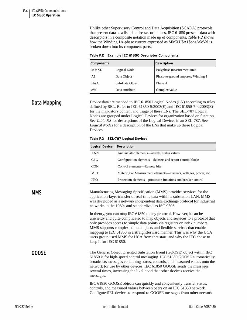
F.4
SEL-787 Relay Instruction Manual Date Code 20150130
IEC 61850 CommunicationsIEC 61850 Operation
Unlike other Supervisory Control and Data Acquisition (SCADA) protocols that present data as a list of addresses or indices, IEC 61850 presents data with descriptors in a composite notation made up of components. Table F.2 shows how the Winding 1A-phase current expressed as MMXU$A1$phsA$cVal is broken down into its component parts.
Data Mapping Device data are mapped to IEC 61850 Logical Nodes (LN) according to rules defined by SEL. Refer to IEC 61850-5:2003(E) and IEC 61850-7-4:2003(E) for the mandatory content and usage of these LNs. The SEL-787 Logical Nodes are grouped under Logical Devices for organization based on function. See Table F.3 for descriptions of the Logical Devices in an SEL-787. See Logical Nodes for a description of the LNs that make up these Logical Devices.
MMS Manufacturing Messaging Specification (MMS) provides services for the application-layer transfer of real-time data within a substation LAN. MMS was developed as a network independent data exchange protocol for industrial networks in the 1980s and standardized as ISO 9506.
In theory, you can map IEC 61850 to any protocol. However, it can be unwieldy and quite complicated to map objects and services to a protocol that only provides access to simple data points via registers or index numbers. MMS supports complex named objects and flexible services that enable mapping to IEC 61850 in a straightforward manner. This was why the UCA users group used MMS for UCA from that start, and why the IEC chose to keep it for IEC 61850.
GOOSE The Generic Object Oriented Substation Event (GOOSE) object within IEC 61850 is for high-speed control messaging. IEC 61850 GOOSE automatically broadcasts messages containing status, controls, and measured values onto the network for use by other devices. IEC 61850 GOOSE sends the messages several times, increasing the likelihood that other devices receive the messages.
IEC 61850 GOOSE objects can quickly and conveniently transfer status, controls, and measured values between peers on an IEC 61850 network. Configure SEL devices to respond to GOOSE messages from other network
Table F.2 Example IEC 61850 Descriptor Components
Components Description
MMXU Logical Node Polyphase measurement unit
A1 Data Object Phase-to-ground amperes, Winding 1
PhsA Sub-Data Object Phase A
cVal Data Attribute Complex value
Table F.3 SEL-787 Logical Devices
Logical Device Description
ANN Annunciator elements—alarms, status values
CFG Configuration elements—datasets and report control blocks
CON Control elements—Remote bits
MET Metering or Measurement elements—currents, voltages, power, etc.
PRO Protection elements—protection functions and breaker control
F.5
Date Code 20150130 Instruction Manual SEL-787 Relay
IEC 61850 CommunicationsIEC 61850 Operation
with ACSELERATOR Architect. Also, configure outgoing GOOSE messages for SEL devices in ACSELERATOR Architect. See the ACSELERATOR Architect online help for more information.
Each IEC 61850 GOOSE sender includes a text identification string (GOOSE Control Block Reference) in each outgoing message and an Ethernet multicast group address. Devices that receive GOOSE messages use the text identification and multicast group to identify and filter incoming GOOSE messages.
Virtual bits (VB001–VB128) are control inputs that you can map to GOOSE receive messages using ACSELERATOR Architect. See the VBnnn bits in Table F.15 for details on which logical nodes and names are used for these bits. This information can be useful when searching through device data with MMS browsers. If you intend to use any SEL-787 virtual bits for controls, you must create ACSELERATOR Architect equations to define these operations. The Virtual Bit Logical Nodes only contain Virtual Bit status, and only those Virtual Bits that are assigned to an SER report will be able to track bit transitions (via reporting) between LN data update scans.
In addition to the Virtual Bits, the breaker control bits CCn and OCn can also be mapped to GOOSE receive messages.
File Services The Ethernet File System allows reading or writing data as files. The File System supports FTP. The File System provides:
➤ A means for the devices to transfer data as files
➤ A hierarchical file structure for the device data (root level only for SEL-700 series devices)
SCL Files Substation Configuration Language (SCL) is an XML-based configuration language used to support the exchange of database configuration data between different tools, which may come from different manufacturers. There are four types of SCL files:
➤ IED Capability Description file (.ICD)
➤ System Specification Description (.SSD) file
➤ Substation Configuration Description file (.SCD)
➤ Configured IED Description file (.CID)
The ICD file described the capabilities of an IED, including information on LN and GOOSE support. The SSD file describes the single-line diagram of the substation and the required LNs. The SCD file contains information on all IEDs, communications configuration data, and a substation description. The CID file, of which there may be several, describes a single instantiated IED within the project, and includes address information.
Reports The SEL-787 supports buffered and unbuffered report control blocks in the report model as defined in IEC 61850-8-1:2004(E). The predefined reports shown in Figure F.1 are available by default via IEC 61850.
NOTE: Any device bits mapped to GOOSE subscriptions retain state until overwritten or the device restarts. When loading a new CID file, be sure to issue an STA C command or cycle power to the device to clear the device bits if the configuration has changed.
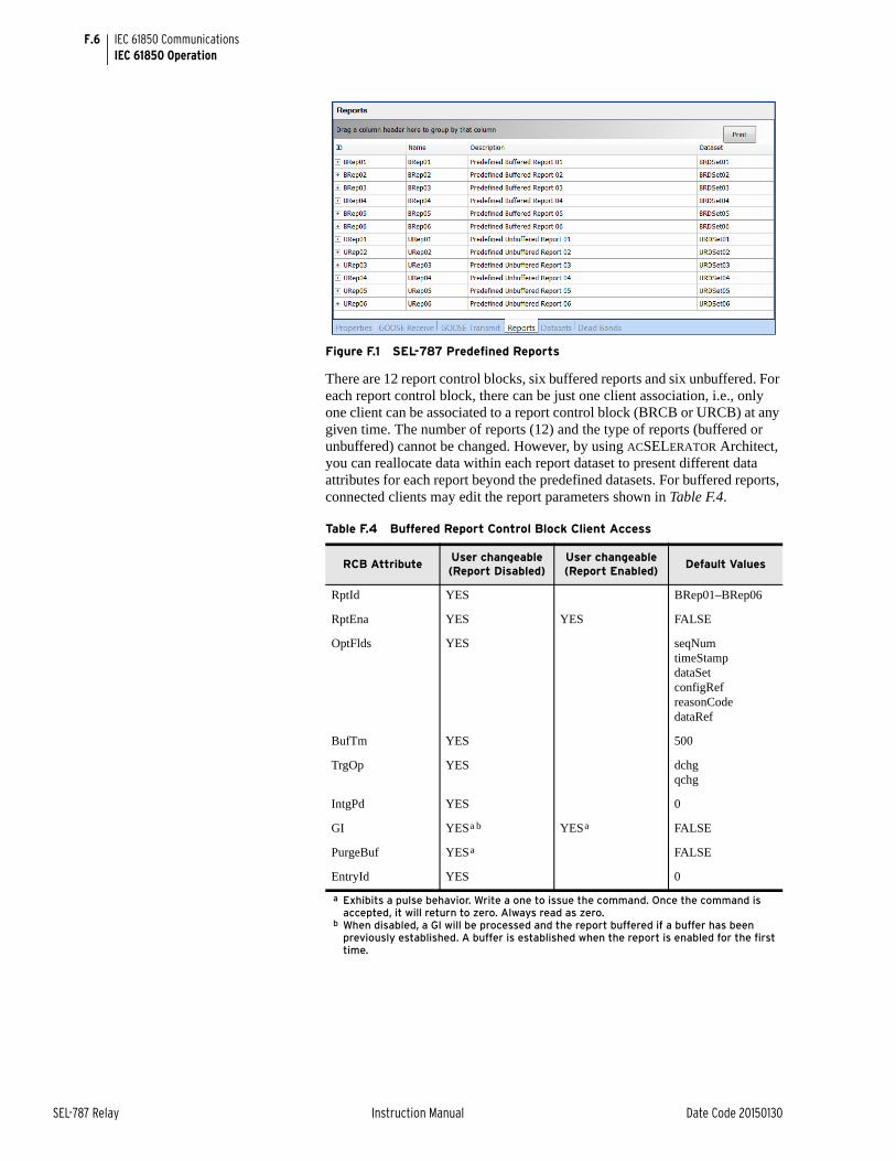
F.6
SEL-787 Relay Instruction Manual Date Code 20150130
IEC 61850 CommunicationsIEC 61850 Operation
Figure F.1 SEL-787 Predefined Reports
There are 12 report control blocks, six buffered reports and six unbuffered. For each report control block, there can be just one client association, i.e., only one client can be associated to a report control block (BRCB or URCB) at any given time. The number of reports (12) and the type of reports (buffered or unbuffered) cannot be changed. However, by using ACSELERATOR Architect, you can reallocate data within each report dataset to present different data attributes for each report beyond the predefined datasets. For buffered reports, connected clients may edit the report parameters shown in Table F.4.
Table F.4 Buffered Report Control Block Client Access
RCB AttributeUser changeable (Report Disabled)
User changeable (Report Enabled)
Default Values
RptId YES BRep01–BRep06
RptEna YES YES FALSE
OptFlds YES seqNumtimeStampdataSetconfigRefreasonCodedataRef
BufTm YES 500
TrgOp YES dchgqchg
IntgPd YES 0
GI YESa b
a Exhibits a pulse behavior. Write a one to issue the command. Once the command is accepted, it will return to zero. Always read as zero.
b When disabled, a GI will be processed and the report buffered if a buffer has been previously established. A buffer is established when the report is enabled for the first time.
YESa FALSE
PurgeBuf YESa FALSE
EntryId YES 0
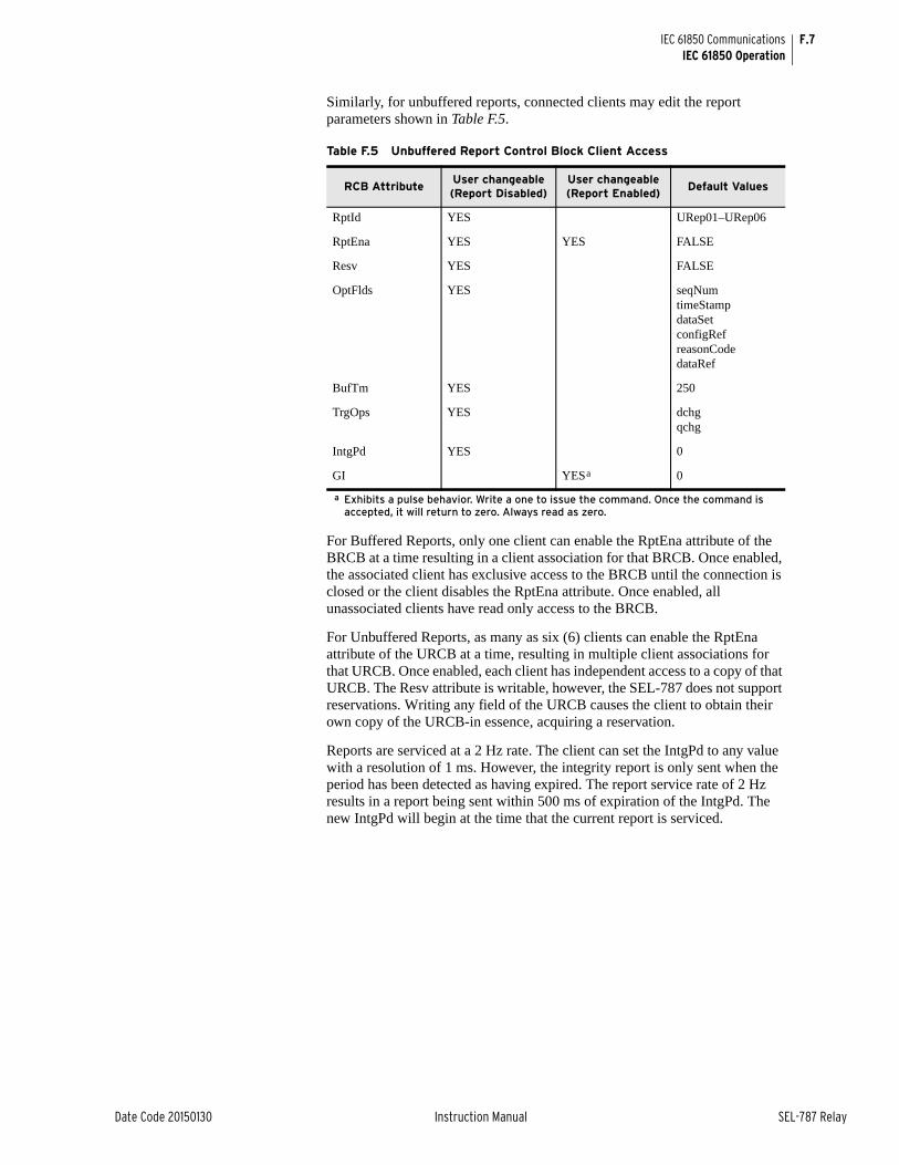
F.7
Date Code 20150130 Instruction Manual SEL-787 Relay
IEC 61850 CommunicationsIEC 61850 Operation
Similarly, for unbuffered reports, connected clients may edit the report parameters shown in Table F.5.
For Buffered Reports, only one client can enable the RptEna attribute of the BRCB at a time resulting in a client association for that BRCB. Once enabled, the associated client has exclusive access to the BRCB until the connection is closed or the client disables the RptEna attribute. Once enabled, all unassociated clients have read only access to the BRCB.
For Unbuffered Reports, as many as six (6) clients can enable the RptEna attribute of the URCB at a time, resulting in multiple client associations for that URCB. Once enabled, each client has independent access to a copy of that URCB. The Resv attribute is writable, however, the SEL-787 does not support reservations. Writing any field of the URCB causes the client to obtain their own copy of the URCB-in essence, acquiring a reservation.
Reports are serviced at a 2 Hz rate. The client can set the IntgPd to any value with a resolution of 1 ms. However, the integrity report is only sent when the period has been detected as having expired. The report service rate of 2 Hz results in a report being sent within 500 ms of expiration of the IntgPd. The new IntgPd will begin at the time that the current report is serviced.
Table F.5 Unbuffered Report Control Block Client Access
RCB AttributeUser changeable (Report Disabled)
User changeable (Report Enabled)
Default Values
RptId YES URep01–URep06
RptEna YES YES FALSE
Resv YES FALSE
OptFlds YES seqNumtimeStampdataSetconfigRefreasonCodedataRef
BufTm YES 250
TrgOps YES dchgqchg
IntgPd YES 0
GI YESa
a Exhibits a pulse behavior. Write a one to issue the command. Once the command is accepted, it will return to zero. Always read as zero.
0
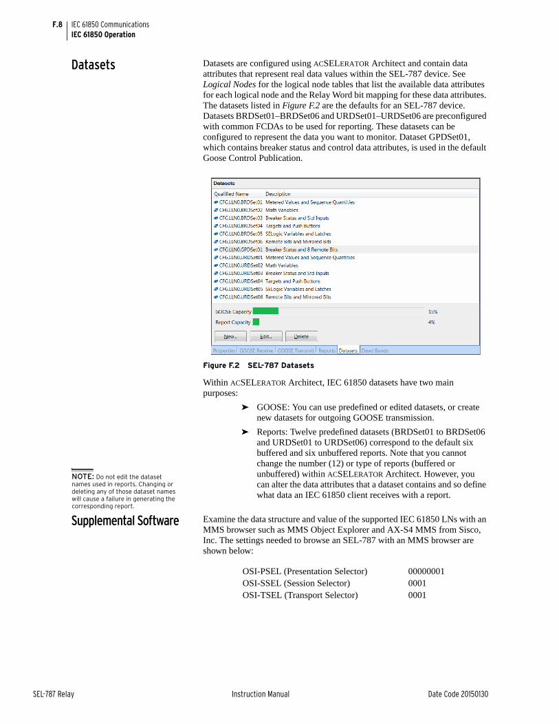
F.8
SEL-787 Relay Instruction Manual Date Code 20150130
IEC 61850 CommunicationsIEC 61850 Operation
Datasets Datasets are configured using ACSELERATOR Architect and contain data attributes that represent real data values within the SEL-787 device. See Logical Nodes for the logical node tables that list the available data attributes for each logical node and the Relay Word bit mapping for these data attributes. The datasets listed in Figure F.2 are the defaults for an SEL-787 device. Datasets BRDSet01–BRDSet06 and URDSet01–URDSet06 are preconfigured with common FCDAs to be used for reporting. These datasets can be configured to represent the data you want to monitor. Dataset GPDSet01, which contains breaker status and control data attributes, is used in the default Goose Control Publication.
Figure F.2 SEL-787 Datasets
Within ACSELERATOR Architect, IEC 61850 datasets have two main purposes:
➤ GOOSE: You can use predefined or edited datasets, or create new datasets for outgoing GOOSE transmission.
➤ Reports: Twelve predefined datasets (BRDSet01 to BRDSet06 and URDSet01 to URDSet06) correspond to the default six buffered and six unbuffered reports. Note that you cannot change the number (12) or type of reports (buffered or unbuffered) within ACSELERATOR Architect. However, you can alter the data attributes that a dataset contains and so define what data an IEC 61850 client receives with a report.
Supplemental Software Examine the data structure and value of the supported IEC 61850 LNs with an MMS browser such as MMS Object Explorer and AX-S4 MMS from Sisco, Inc. The settings needed to browse an SEL-787 with an MMS browser are shown below:
NOTE: Do not edit the dataset names used in reports. Changing or deleting any of those dataset names will cause a failure in generating the corresponding report.
OSI-PSEL (Presentation Selector) 00000001OSI-SSEL (Session Selector) 0001OSI-TSEL (Transport Selector) 0001
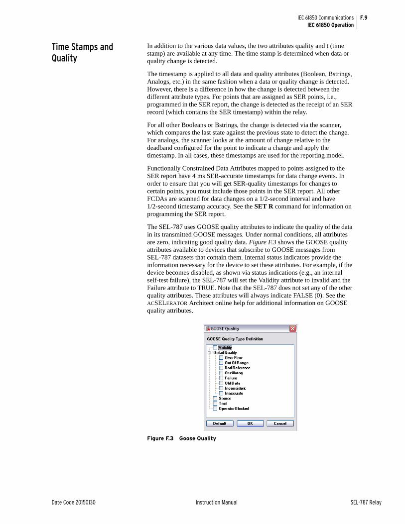
F.9
Date Code 20150130 Instruction Manual SEL-787 Relay
IEC 61850 CommunicationsIEC 61850 Operation
Time Stamps and Quality
In addition to the various data values, the two attributes quality and t (time stamp) are available at any time. The time stamp is determined when data or quality change is detected.
The timestamp is applied to all data and quality attributes (Boolean, Bstrings, Analogs, etc.) in the same fashion when a data or quality change is detected. However, there is a difference in how the change is detected between the different attribute types. For points that are assigned as SER points, i.e., programmed in the SER report, the change is detected as the receipt of an SER record (which contains the SER timestamp) within the relay.
For all other Booleans or Bstrings, the change is detected via the scanner, which compares the last state against the previous state to detect the change. For analogs, the scanner looks at the amount of change relative to the deadband configured for the point to indicate a change and apply the timestamp. In all cases, these timestamps are used for the reporting model.
Functionally Constrained Data Attributes mapped to points assigned to the SER report have 4 ms SER-accurate timestamps for data change events. In order to ensure that you will get SER-quality timestamps for changes to certain points, you must include those points in the SER report. All other FCDAs are scanned for data changes on a 1/2-second interval and have 1/2-second timestamp accuracy. See the SET R command for information on programming the SER report.
The SEL-787 uses GOOSE quality attributes to indicate the quality of the data in its transmitted GOOSE messages. Under normal conditions, all attributes are zero, indicating good quality data. Figure F.3 shows the GOOSE quality attributes available to devices that subscribe to GOOSE messages from SEL-787 datasets that contain them. Internal status indicators provide the information necessary for the device to set these attributes. For example, if the device becomes disabled, as shown via status indications (e.g., an internal self-test failure), the SEL-787 will set the Validity attribute to invalid and the Failure attribute to TRUE. Note that the SEL-787 does not set any of the other quality attributes. These attributes will always indicate FALSE (0). See the ACSELERATOR Architect online help for additional information on GOOSE quality attributes.
Figure F.3 Goose Quality

F.10
SEL-787 Relay Instruction Manual Date Code 20150130
IEC 61850 CommunicationsIEC 61850 Operation
GOOSE Processing SEL devices support GOOSE processing as defined by IEC 61850-7-1:2003(E), IEC 61850-7-2:2003(E), and IEC 61850-8-1:2004(E) via the installed Ethernet port. Outgoing GOOSE messages are processed in accordance with the following constraints:
➤ The user can define as many as eight outgoing GOOSE messages consisting of any Data Attribute (DA) from any Logical Node. A single DA can be mapped to one or more outgoing GOOSE, or one or more times within the same outgoing GOOSE. A user can also map a single GOOSE dataset to multiple GOOSE control blocks.
➤ The SEL-787 will transmit all configured GOOSE immediately upon successful initialization. If a GOOSE is not retriggered, then, following initial transmission, the SEL-787 will retransmit that GOOSE on a curve. The curve begins at 10 ms and doubles for each retransmission until leveling at the maximum specified in the CID file for that GOOSE. For example, a message with a maximum retransmit interval of 100 ms is retransmitted at intervals of 10 ms, 20 ms, 40 ms, 80 ms, and 100 ms, then repeated every 100 ms until a trigger causes the transmission sequence to be repeated. The time-to-live reported in each transmitted message, is three times the current interval, or two times the interval, if the maximum time-to-live has been reached (30 ms, 60 ms, 120 ms, 240 ms, and 200 ms for the example above; see IEC 61850-8-1, sec. 18.1).
➤ GOOSE transmission is squelched (silenced) after a permanent (latching) self-test failure.
➤ Each outgoing GOOSE includes communication parameters (VLAN, Priority, and Multicast Address) and is transmitted entirely in a single network frame.
➤ The SEL-787 will maintain the configuration of outgoing GOOSE through a power cycle and device reset.
Incoming GOOSE messages are processed in accordance with the following constraints:
➤ The user can configure the SEL-787 to subscribe to as many as 16 incoming GOOSE messages.
The SEL-787 will recognize incoming GOOSE messages as valid based on the following content. Any GOOSE message that fails these checks shall be rejected.
➢ Source broadcast MAC address
➢ Dataset Reference
➢ Application ID
➢ GOOSE Control Reference
➤ Rejection of all DA contained in an incoming GOOSE, based on the accumulation of the following error indications created by inspection of the received GOOSE:
➢ Configuration Mismatch: the configuration number of the incoming GOOSE changes.
➢ Needs Commissioning: this Boolean parameter of the incoming GOOSE is true.
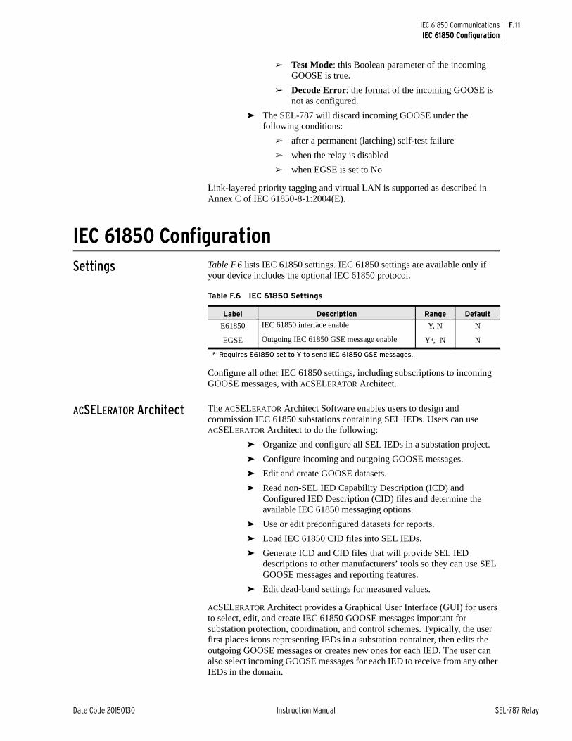
F.11
Date Code 20150130 Instruction Manual SEL-787 Relay
IEC 61850 CommunicationsIEC 61850 Configuration
➢ Test Mode: this Boolean parameter of the incoming GOOSE is true.
➢ Decode Error: the format of the incoming GOOSE is not as configured.
➤ The SEL-787 will discard incoming GOOSE under the following conditions:
➢ after a permanent (latching) self-test failure
➢ when the relay is disabled
➢ when EGSE is set to No
Link-layered priority tagging and virtual LAN is supported as described in Annex C of IEC 61850-8-1:2004(E).
IEC 61850 ConfigurationSettings Table F.6 lists IEC 61850 settings. IEC 61850 settings are available only if
your device includes the optional IEC 61850 protocol.
Configure all other IEC 61850 settings, including subscriptions to incoming GOOSE messages, with ACSELERATOR Architect.
ACSELERATOR Architect The ACSELERATOR Architect Software enables users to design and commission IEC 61850 substations containing SEL IEDs. Users can use ACSELERATOR Architect to do the following:
➤ Organize and configure all SEL IEDs in a substation project.
➤ Configure incoming and outgoing GOOSE messages.
➤ Edit and create GOOSE datasets.
➤ Read non-SEL IED Capability Description (ICD) and Configured IED Description (CID) files and determine the available IEC 61850 messaging options.
➤ Use or edit preconfigured datasets for reports.
➤ Load IEC 61850 CID files into SEL IEDs.
➤ Generate ICD and CID files that will provide SEL IED descriptions to other manufacturers’ tools so they can use SEL GOOSE messages and reporting features.
➤ Edit dead-band settings for measured values.
ACSELERATOR Architect provides a Graphical User Interface (GUI) for users to select, edit, and create IEC 61850 GOOSE messages important for substation protection, coordination, and control schemes. Typically, the user first places icons representing IEDs in a substation container, then edits the outgoing GOOSE messages or creates new ones for each IED. The user can also select incoming GOOSE messages for each IED to receive from any other IEDs in the domain.
Table F.6 IEC 61850 Settings
Label Description Range Default
E61850 IEC 61850 interface enable Y, N N
EGSE Outgoing IEC 61850 GSE message enable Ya, N
a Requires E61850 set to Y to send IEC 61850 GSE messages.
N
F.12
SEL-787 Relay Instruction Manual Date Code 20150130
IEC 61850 CommunicationsIEC 61850 Configuration
Some measured values are reported to IEC 61850 only when the value changes beyond a defined dead-band value. ACSELERATOR Architect allows a dead band to be changed during the CID file configuration. Check and set the dead-band values for your particular application when configuring the CID file for a device.
ACSELERATOR Architect has the capability to read other manufacturers’ ICD and CID files, enabling the user to map the data seamlessly into SEL IED logic. See the ACSELERATOR Architect online help for more information.
SEL ICD File Versions ACSELERATOR Architect generates CID files from ICD files so the ICD file version ACSELERATOR Architect uses also determines the CID file version generated. Details about the different SEL-787 ICD files can be found in Table A.5.
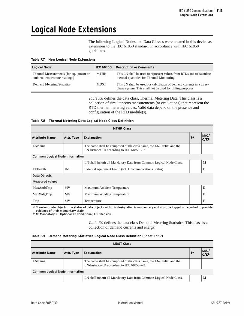
F.13
Date Code 20150130 Instruction Manual SEL-787 Relay
IEC 61850 CommunicationsLogical Node Extensions
Logical Node ExtensionsThe following Logical Nodes and Data Classes were created in this device as extensions to the IEC 61850 standard, in accordance with IEC 61850 guidelines.
Table F.8 defines the data class, Thermal Metering Data. This class is a collection of simultaneous measurements (or evaluations) that represent the RTD thermal metering values. Valid data depend on the presence and configuration of the RTD module(s).
Table F.9 defines the data class Demand Metering Statistics. This class is a collection of demand currents and energy.
Table F.7 New Logical Node Extensions
Logical Node IEC 61850 Description or Comments
Thermal Measurements (for equipment or ambient temperature readings)
MTHR This LN shall be used to represent values from RTDs and to calculate thermal quantities for Thermal Monitoring.
Demand Metering Statistics MDST This LN shall be used for calculation of demand currents in a three-phase system. This shall not be used for billing purposes.
Table F.8 Thermal Metering Data Logical Node Class Definition
MTHR Class
Attribute Name Attr. Type Explanation Ta
a Transient data objects—the status of data objects with this designation is momentary and must be logged or reported to provide evidence of their momentary state
M/O/C/Eb
b M: Mandatory; O: Optional; C: Conditional; E: Extension
LNName The name shall be composed of the class name, the LN-Prefix, and the LN-Instance-ID according to IEC 61850-7-2.
Common Logical Node Information
LN shall inherit all Mandatory Data from Common Logical Node Class. M
EEHealth INS External equipment health (RTD Communications Status) E
Data Objects
Measured values
MaxAmbTmp MV Maximum Ambient Temperature E
MaxWdgTmp MV Maximum Winding Temperature E
Tmp MV Temperature E
Table F.9 Demand Metering Statistics Logical Node Class Definition (Sheet 1 of 2)
MDST Class
Attribute Name Attr. Type Explanation Ta M/O/C/Eb
LNName The name shall be composed of the class name, the LN-Prefix, and the LN-Instance-ID according to IEC 61850-7-2.
Common Logical Node Information
LN shall inherit all Mandatory Data from Common Logical Node Class. M

F.14
SEL-787 Relay Instruction Manual Date Code 20150130
IEC 61850 CommunicationsLogical Node Extensions
Data Objects
Measured values
DmdA WYE Demand Currents E
PkDmdA WYE Peak Demand Currents E
SupWh MV Real energy supply (default supply direction: energy flow towards busbar)
E
SupVArh MV Reactive energy supply (default supply direction: energy flow towards busbar)
E
DmdWh MV Real energy demand (default demand direction: energy flow from busbar away)
E
DmdVArh MV Reactive energy demand (default demand direction: energy flow from busbar away)
E
a Transient data objects—the status of data objects with this designation is momentary and must be logged or reported to provide evidence of their momentary state
b M: Mandatory; O: Optional; C: Conditional; E: Extension
Table F.10 Compatible Logical Nodes With Extensions
Logical Node IEC 61850 Description or Comments
Metering Statistics MSTA This LN is used for power system metering statistics.
Table F.9 Demand Metering Statistics Logical Node Class Definition (Sheet 2 of 2)
MDST Class
Attribute Name Attr. Type Explanation Ta M/O/C/Eb
Table F.11 Metering Statistics Logical Node Class Definition (Sheet 1 of 2)
MSTA Class
Attribute Name Attr. Type Explanation Ta M/O/C/Eb
LNName The name shall be composed of the class name, the LN-Prefix, and the LN-Instance-ID according to IEC 61850-7-2.
Common Logical Node Information
LN shall inherit all Mandatory Data from Common Logical Node Class. M
Data Objects
Measured and Metered values
AvAmps MV Average Current O
AvVolts MV Average Voltage O
MaxVA MV Maximum apparent power O
MinVA MV Minimum apparent power O
MaxW MV Maximum real power O
MinW MV Minimum real power O
MaxVAr MV Maximum reactive power O
MinVAr MV Minimum reactive power O
MaxA WYE Maximum Phase Currents E
MinA WYE Minimum Phase Currents E
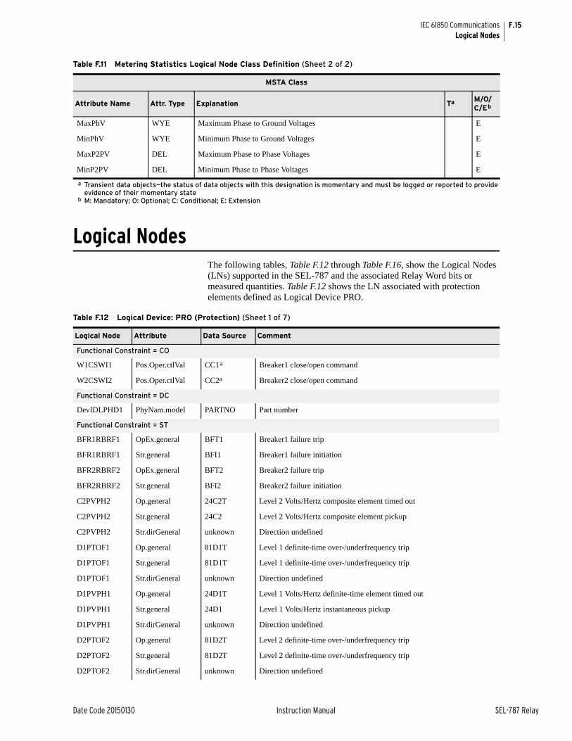
F.15
Date Code 20150130 Instruction Manual SEL-787 Relay
IEC 61850 CommunicationsLogical Nodes
Logical NodesThe following tables, Table F.12 through Table F.16, show the Logical Nodes (LNs) supported in the SEL-787 and the associated Relay Word bits or measured quantities. Table F.12 shows the LN associated with protection elements defined as Logical Device PRO.
MaxPhV WYE Maximum Phase to Ground Voltages E
MinPhV WYE Minimum Phase to Ground Voltages E
MaxP2PV DEL Maximum Phase to Phase Voltages E
MinP2PV DEL Minimum Phase to Phase Voltages E
a Transient data objects—the status of data objects with this designation is momentary and must be logged or reported to provide evidence of their momentary state
b M: Mandatory; O: Optional; C: Conditional; E: Extension
Table F.11 Metering Statistics Logical Node Class Definition (Sheet 2 of 2)
MSTA Class
Attribute Name Attr. Type Explanation Ta M/O/C/Eb
Table F.12 Logical Device: PRO (Protection) (Sheet 1 of 7)
Logical Node Attribute Data Source Comment
Functional Constraint = CO
W1CSWI1 Pos.Oper.ctlVal CC1a Breaker1 close/open command
W2CSWI2 Pos.Oper.ctlVal CC2a Breaker2 close/open command
Functional Constraint = DC
DevIDLPHD1 PhyNam.model PARTNO Part number
Functional Constraint = ST
BFR1RBRF1 OpEx.general BFT1 Breaker1 failure trip
BFR1RBRF1 Str.general BFI1 Breaker1 failure initiation
BFR2RBRF2 OpEx.general BFT2 Breaker2 failure trip
BFR2RBRF2 Str.general BFI2 Breaker2 failure initiation
C2PVPH2 Op.general 24C2T Level 2 Volts/Hertz composite element timed out
C2PVPH2 Str.general 24C2 Level 2 Volts/Hertz composite element pickup
C2PVPH2 Str.dirGeneral unknown Direction undefined
D1PTOF1 Op.general 81D1T Level 1 definite-time over-/underfrequency trip
D1PTOF1 Str.general 81D1T Level 1 definite-time over-/underfrequency trip
D1PTOF1 Str.dirGeneral unknown Direction undefined
D1PVPH1 Op.general 24D1T Level 1 Volts/Hertz definite-time element timed out
D1PVPH1 Str.general 24D1 Level 1 Volts/Hertz instantaneous pickup
D1PVPH1 Str.dirGeneral unknown Direction undefined
D2PTOF2 Op.general 81D2T Level 2 definite-time over-/underfrequency trip
D2PTOF2 Str.general 81D2T Level 2 definite-time over-/underfrequency trip
D2PTOF2 Str.dirGeneral unknown Direction undefined
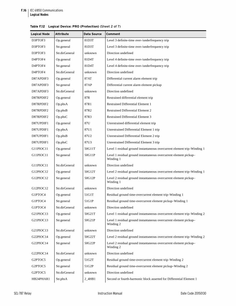
F.16
SEL-787 Relay Instruction Manual Date Code 20150130
IEC 61850 CommunicationsLogical Nodes
D3PTOF3 Op.general 81D3T Level 3 definite-time over-/underfrequency trip
D3PTOF3 Str.general 81D3T Level 3 definite-time over-/underfrequency trip
D3PTOF3 Str.dirGeneral unknown Direction undefined
D4PTOF4 Op.general 81D4T Level 4 definite-time over-/underfrequency trip
D4PTOF4 Str.general 81D4T Level 4 definite-time over-/underfrequency trip
D4PTOF4 Str.dirGeneral unknown Direction undefined
D87APDIF3 Op.general 87AT Differential current alarm element trip
D87APDIF3 Str.general 87AP Differential current alarm element pickup
D87APDIF3 Str.dirGeneral unknown Direction undefined
D87RPDIF2 Op.general 87R Restrained differential element trip
D87RPDIF2 Op.phsA 87R1 Restrained Differential Element 1
D87RPDIF2 Op.phsB 87R2 Restrained Differential Element 2
D87RPDIF2 Op.phsC 87R3 Restrained Differential Element 3
D87UPDIF1 Op.general 87U Unrestrained differential element trip
D87UPDIF1 Op.phsA 87U1 Unrestrained Differential Element 1 trip
D87UPDIF1 Op.phsB 87U2 Unrestrained Differential Element 2 trip
D87UPDIF1 Op.phsC 87U3 Unrestrained Differential Element 3 trip
G11PIOC11 Op.general 50G11T Level 1 residual ground instantaneous overcurrent element trip–Winding 1
G11PIOC11 Str.general 50G11P Level 1 residual ground instantaneous overcurrent element pickup–Winding 1
G11PIOC11 Str.dirGeneral unknown Direction undefined
G12PIOC12 Op.general 50G12T Level 2 residual ground instantaneous overcurrent element trip–Winding 1
G12PIOC12 Str.general 50G12P Level 2 residual ground instantaneous overcurrent element pickup–Winding 1
G12PIOC12 Str.dirGeneral unknown Direction undefined
G1PTOC4 Op.general 51G1T Residual ground time-overcurrent element trip–Winding 1
G1PTOC4 Str.general 51G1P Residual ground time-overcurrent element pickup–Winding 1
G1PTOC4 Str.dirGeneral unknown Direction undefined
G21PIOC13 Op.general 50G21T Level 1 residual ground instantaneous overcurrent element trip–Winding 2
G21PIOC13 Str.general 50G21P Level 1 residual ground instantaneous overcurrent element pickup–Winding 2
G21PIOC13 Str.dirGeneral unknown Direction undefined
G22PIOC14 Op.general 50G22T Level 2 residual ground instantaneous overcurrent element trip–Winding 2
G22PIOC14 Str.general 50G22P Level 2 residual ground instantaneous overcurrent element pickup–Winding 2
G22PIOC14 Str.dirGeneral unknown Direction undefined
G2PTOC5 Op.general 51G2T Residual ground time-overcurrent element trip–Winding 2
G2PTOC5 Str.general 51G2P Residual ground time-overcurrent element pickup–Winding 2
G2PTOC5 Str.dirGeneral unknown Direction undefined
HB24PHAR1 Str.phsA 2_4HB1 Second or fourth-harmonic block asserted for Differential Element 1
Table F.12 Logical Device: PRO (Protection) (Sheet 2 of 7)
Logical Node Attribute Data Source Comment
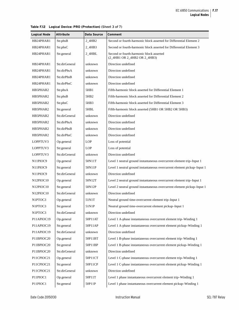
F.17
Date Code 20150130 Instruction Manual SEL-787 Relay
IEC 61850 CommunicationsLogical Nodes
HB24PHAR1 Str.phsB 2_4HB2 Second or fourth-harmonic block asserted for Differential Element 2
HB24PHAR1 Str.phsC 2_4HB3 Second or fourth-harmonic block asserted for Differential Element 3
HB24PHAR1 Str.general 2_4HBL Second or fourth-harmonic block asserted (2_4HB1 OR 2_4HB2 OR 2_4HB3)
HB24PHAR1 Str.dirGeneral unknown Direction undefined
HB24PHAR1 Str.dirPhsA unknown Direction undefined
HB24PHAR1 Str.dirPhsB unknown Direction undefined
HB24PHAR1 Str.dirPhsC unknown Direction undefined
HB5PHAR2 Str.phsA 5HB1 Fifth-harmonic block asserted for Differential Element 1
HB5PHAR2 Str.phsB 5HB2 Fifth-harmonic block asserted for Differential Element 2
HB5PHAR2 Str.phsC 5HB3 Fifth-harmonic block asserted for Differential Element 3
HB5PHAR2 Str.general 5HBL Fifth-harmonic block asserted (5HB1 OR 5HB2 OR 5HB3)
HB5PHAR2 Str.dirGeneral unknown Direction undefined
HB5PHAR2 Str.dirPhsA unknown Direction undefined
HB5PHAR2 Str.dirPhsB unknown Direction undefined
HB5PHAR2 Str.dirPhsC unknown Direction undefined
LOPPTUV3 Op.general LOP Loss of potential
LOPPTUV3 Str.general LOP Loss of potential
LOPPTUV3 Str.dirGeneral unknown Direction undefined
N11PIOC9 Op.general 50N11T Level 1 neutral ground instantaneous overcurrent element trip–Input 1
N11PIOC9 Str.general 50N11P Level 1 neutral ground instantaneous overcurrent element pickup–Input 1
N11PIOC9 Str.dirGeneral unknown Direction undefined
N12PIOC10 Op.general 50N12T Level 2 neutral ground instantaneous overcurrent element trip–Input 1
N12PIOC10 Str.general 50N12P Level 2 neutral ground instantaneous overcurrent element pickup–Input 1
N12PIOC10 Str.dirGeneral unknown Direction undefined
N1PTOC3 Op.general 51N1T Neutral ground time-overcurrent element trip–Input 1
N1PTOC3 Str.general 51N1P Neutral ground time-overcurrent element pickup–Input 1
N1PTOC3 Str.dirGeneral unknown Direction undefined
P11APIOC19 Op.general 50P11AT Level 1 A-phase instantaneous overcurrent element trip–Winding 1
P11APIOC19 Str.general 50P11AP Level 1 A-phase instantaneous overcurrent element pickup–Winding 1
P11APIOC19 Str.dirGeneral unknown Direction undefined
P11BPIOC20 Op.general 50P11BT Level 1 B-phase instantaneous overcurrent element trip–Winding 1
P11BPIOC20 Str.general 50P11BP Level 1 B-phase instantaneous overcurrent element pickup–Winding 1
P11BPIOC20 Str.dirGeneral unknown Direction undefined
P11CPIOC21 Op.general 50P11CT Level 1 C-phase instantaneous overcurrent element trip–Winding 1
P11CPIOC21 Str.general 50P11CP Level 1 C-phase instantaneous overcurrent element pickup–Winding 1
P11CPIOC21 Str.dirGeneral unknown Direction undefined
P11PIOC1 Op.general 50P11T Level 1 phase instantaneous overcurrent element trip–Winding 1
P11PIOC1 Str.general 50P11P Level 1 phase instantaneous overcurrent element pickup–Winding 1
Table F.12 Logical Device: PRO (Protection) (Sheet 3 of 7)
Logical Node Attribute Data Source Comment
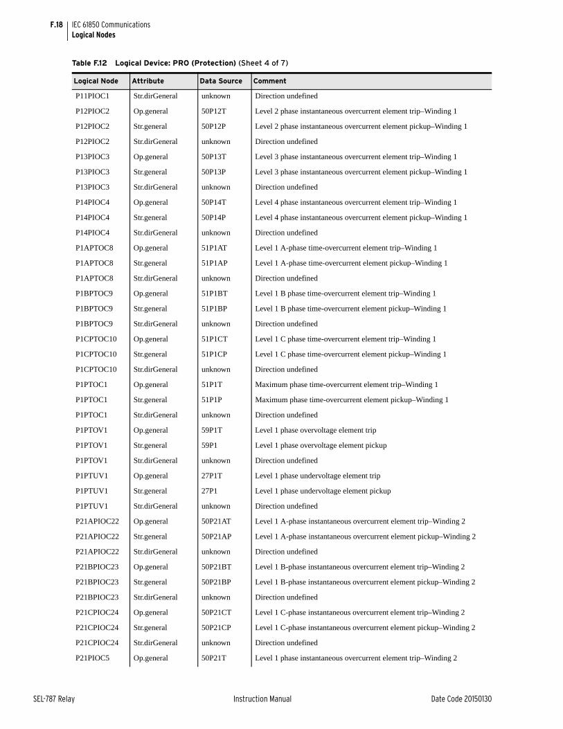
F.18
SEL-787 Relay Instruction Manual Date Code 20150130
IEC 61850 CommunicationsLogical Nodes
P11PIOC1 Str.dirGeneral unknown Direction undefined
P12PIOC2 Op.general 50P12T Level 2 phase instantaneous overcurrent element trip–Winding 1
P12PIOC2 Str.general 50P12P Level 2 phase instantaneous overcurrent element pickup–Winding 1
P12PIOC2 Str.dirGeneral unknown Direction undefined
P13PIOC3 Op.general 50P13T Level 3 phase instantaneous overcurrent element trip–Winding 1
P13PIOC3 Str.general 50P13P Level 3 phase instantaneous overcurrent element pickup–Winding 1
P13PIOC3 Str.dirGeneral unknown Direction undefined
P14PIOC4 Op.general 50P14T Level 4 phase instantaneous overcurrent element trip–Winding 1
P14PIOC4 Str.general 50P14P Level 4 phase instantaneous overcurrent element pickup–Winding 1
P14PIOC4 Str.dirGeneral unknown Direction undefined
P1APTOC8 Op.general 51P1AT Level 1 A-phase time-overcurrent element trip–Winding 1
P1APTOC8 Str.general 51P1AP Level 1 A-phase time-overcurrent element pickup–Winding 1
P1APTOC8 Str.dirGeneral unknown Direction undefined
P1BPTOC9 Op.general 51P1BT Level 1 B phase time-overcurrent element trip–Winding 1
P1BPTOC9 Str.general 51P1BP Level 1 B phase time-overcurrent element pickup–Winding 1
P1BPTOC9 Str.dirGeneral unknown Direction undefined
P1CPTOC10 Op.general 51P1CT Level 1 C phase time-overcurrent element trip–Winding 1
P1CPTOC10 Str.general 51P1CP Level 1 C phase time-overcurrent element pickup–Winding 1
P1CPTOC10 Str.dirGeneral unknown Direction undefined
P1PTOC1 Op.general 51P1T Maximum phase time-overcurrent element trip–Winding 1
P1PTOC1 Str.general 51P1P Maximum phase time-overcurrent element pickup–Winding 1
P1PTOC1 Str.dirGeneral unknown Direction undefined
P1PTOV1 Op.general 59P1T Level 1 phase overvoltage element trip
P1PTOV1 Str.general 59P1 Level 1 phase overvoltage element pickup
P1PTOV1 Str.dirGeneral unknown Direction undefined
P1PTUV1 Op.general 27P1T Level 1 phase undervoltage element trip
P1PTUV1 Str.general 27P1 Level 1 phase undervoltage element pickup
P1PTUV1 Str.dirGeneral unknown Direction undefined
P21APIOC22 Op.general 50P21AT Level 1 A-phase instantaneous overcurrent element trip–Winding 2
P21APIOC22 Str.general 50P21AP Level 1 A-phase instantaneous overcurrent element pickup–Winding 2
P21APIOC22 Str.dirGeneral unknown Direction undefined
P21BPIOC23 Op.general 50P21BT Level 1 B-phase instantaneous overcurrent element trip–Winding 2
P21BPIOC23 Str.general 50P21BP Level 1 B-phase instantaneous overcurrent element pickup–Winding 2
P21BPIOC23 Str.dirGeneral unknown Direction undefined
P21CPIOC24 Op.general 50P21CT Level 1 C-phase instantaneous overcurrent element trip–Winding 2
P21CPIOC24 Str.general 50P21CP Level 1 C-phase instantaneous overcurrent element pickup–Winding 2
P21CPIOC24 Str.dirGeneral unknown Direction undefined
P21PIOC5 Op.general 50P21T Level 1 phase instantaneous overcurrent element trip–Winding 2
Table F.12 Logical Device: PRO (Protection) (Sheet 4 of 7)
Logical Node Attribute Data Source Comment
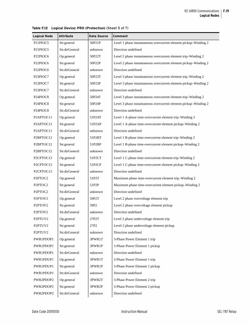
F.19
Date Code 20150130 Instruction Manual SEL-787 Relay
IEC 61850 CommunicationsLogical Nodes
P21PIOC5 Str.general 50P21P Level 1 phase instantaneous overcurrent element pickup–Winding 2
P21PIOC5 Str.dirGeneral unknown Direction undefined
P22PIOC6 Op.general 50P22T Level 2 phase instantaneous overcurrent element trip–Winding 2
P22PIOC6 Str.general 50P22P Level 2 phase instantaneous overcurrent element pickup–Winding 2
P22PIOC6 Str.dirGeneral unknown Direction undefined
P23PIOC7 Op.general 50P23T Level 3 phase instantaneous overcurrent element trip–Winding 2
P23PIOC7 Str.general 50P23P Level 3 phase instantaneous overcurrent element pickup–Winding 2
P23PIOC7 Str.dirGeneral unknown Direction undefined
P24PIOC8 Op.general 50P24T Level 3 phase instantaneous overcurrent element trip–Winding 2
P24PIOC8 Str.general 50P24P Level 3 phase instantaneous overcurrent element pickup–Winding 2
P24PIOC8 Str.dirGeneral unknown Direction undefined
P2APTOC11 Op.general 51P2AT Level 1 A-phase time-overcurrent element trip–Winding 2
P2APTOC11 Str.general 51P2AP Level 1 A-phase time-overcurrent element pickup–Winding 2
P2APTOC11 Str.dirGeneral unknown Direction undefined
P2BPTOC12 Op.general 51P2BT Level 1 B-phase time-overcurrent element trip–Winding 2
P2BPTOC12 Str.general 51P2BP Level 1 B-phase time-overcurrent element pickup–Winding 2
P2BPTOC12 Str.dirGeneral unknown Direction undefined
P2CPTOC13 Op.general 51P2CT Level 1 C-phase time-overcurrent element trip–Winding 2
P2CPTOC13 Str.general 51P2CP Level 1 C-phase time-overcurrent element pickup–Winding 2
P2CPTOC13 Str.dirGeneral unknown Direction undefined
P2PTOC2 Op.general 51P2T Maximum phase time-overcurrent element trip–Winding 2
P2PTOC2 Str.general 51P2P Maximum phase time-overcurrent element pickup–Winding 2
P2PTOC2 Str.dirGeneral unknown Direction undefined
P2PTOV2 Op.general 59P2T Level 2 phase overvoltage element trip
P2PTOV2 Str.general 59P2 Level 2 phase overvoltage element pickup
P2PTOV2 Str.dirGeneral unknown Direction undefined
P2PTUV2 Op.general 27P2T Level 2 phase undervoltage element trip
P2PTUV2 Str.general 27P2 Level 2 phase undervoltage element pickup
P2PTUV2 Str.dirGeneral unknown Direction undefined
PWR1PDOP1 Op.general 3PWR1T 3-Phase Power Element 1 trip
PWR1PDOP1 Str.general 3PWR1P 3-Phase Power Element 1 pickup
PWR1PDOP1 Str.dirGeneral unknown Direction undefined
PWR1PDUP1 Op.general 3PWR1T 3-Phase Power Element 1 trip
PWR1PDUP1 Str.general 3PWR1P 3-Phase Power Element 1 pickup
PWR1PDUP1 Str.dirGeneral unknown Direction undefined
PWR2PDOP2 Op.general 3PWR2T 3-Phase Power Element 2 trip
PWR2PDOP2 Str.general 3PWR2P 3-Phase Power Element 2 pickup
PWR2PDOP2 Str.dirGeneral unknown Direction undefined
Table F.12 Logical Device: PRO (Protection) (Sheet 5 of 7)
Logical Node Attribute Data Source Comment
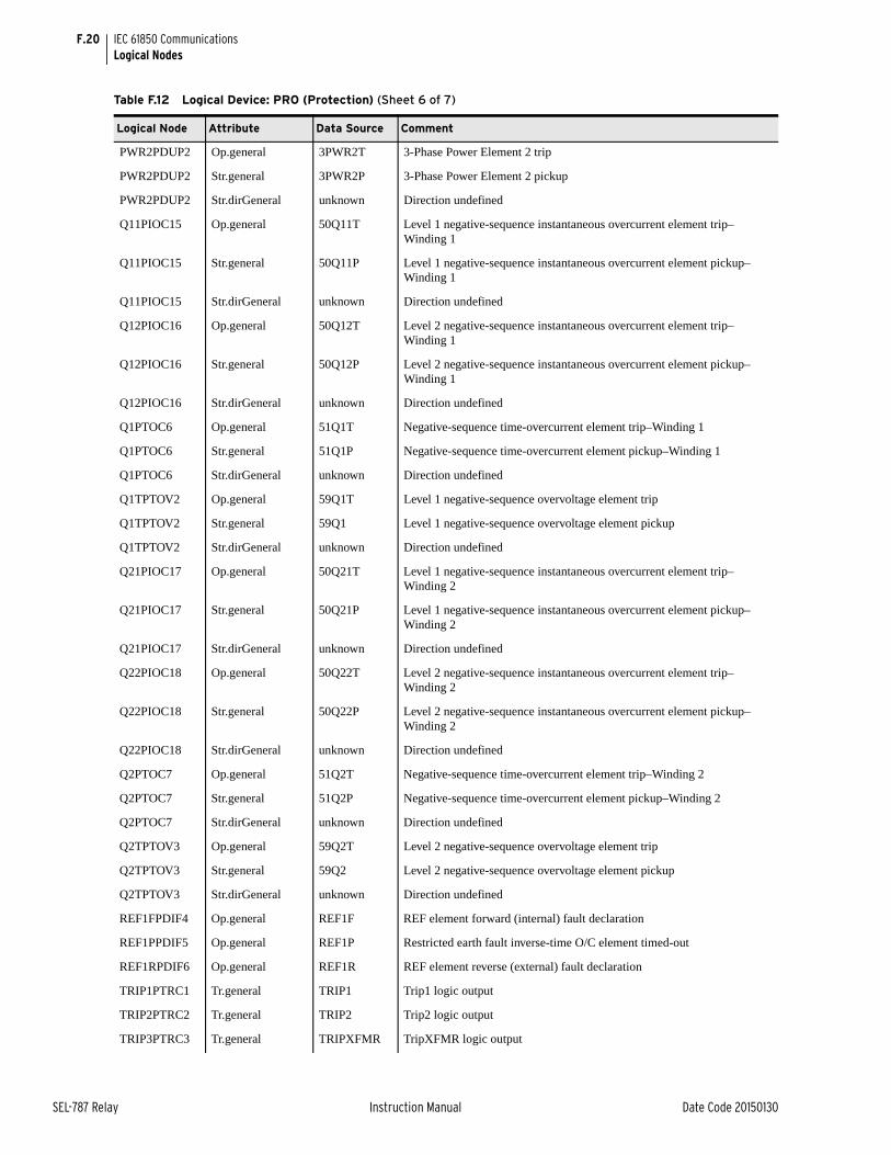
F.20
SEL-787 Relay Instruction Manual Date Code 20150130
IEC 61850 CommunicationsLogical Nodes
PWR2PDUP2 Op.general 3PWR2T 3-Phase Power Element 2 trip
PWR2PDUP2 Str.general 3PWR2P 3-Phase Power Element 2 pickup
PWR2PDUP2 Str.dirGeneral unknown Direction undefined
Q11PIOC15 Op.general 50Q11T Level 1 negative-sequence instantaneous overcurrent element trip–Winding 1
Q11PIOC15 Str.general 50Q11P Level 1 negative-sequence instantaneous overcurrent element pickup–Winding 1
Q11PIOC15 Str.dirGeneral unknown Direction undefined
Q12PIOC16 Op.general 50Q12T Level 2 negative-sequence instantaneous overcurrent element trip–Winding 1
Q12PIOC16 Str.general 50Q12P Level 2 negative-sequence instantaneous overcurrent element pickup–Winding 1
Q12PIOC16 Str.dirGeneral unknown Direction undefined
Q1PTOC6 Op.general 51Q1T Negative-sequence time-overcurrent element trip–Winding 1
Q1PTOC6 Str.general 51Q1P Negative-sequence time-overcurrent element pickup–Winding 1
Q1PTOC6 Str.dirGeneral unknown Direction undefined
Q1TPTOV2 Op.general 59Q1T Level 1 negative-sequence overvoltage element trip
Q1TPTOV2 Str.general 59Q1 Level 1 negative-sequence overvoltage element pickup
Q1TPTOV2 Str.dirGeneral unknown Direction undefined
Q21PIOC17 Op.general 50Q21T Level 1 negative-sequence instantaneous overcurrent element trip–Winding 2
Q21PIOC17 Str.general 50Q21P Level 1 negative-sequence instantaneous overcurrent element pickup–Winding 2
Q21PIOC17 Str.dirGeneral unknown Direction undefined
Q22PIOC18 Op.general 50Q22T Level 2 negative-sequence instantaneous overcurrent element trip–Winding 2
Q22PIOC18 Str.general 50Q22P Level 2 negative-sequence instantaneous overcurrent element pickup–Winding 2
Q22PIOC18 Str.dirGeneral unknown Direction undefined
Q2PTOC7 Op.general 51Q2T Negative-sequence time-overcurrent element trip–Winding 2
Q2PTOC7 Str.general 51Q2P Negative-sequence time-overcurrent element pickup–Winding 2
Q2PTOC7 Str.dirGeneral unknown Direction undefined
Q2TPTOV3 Op.general 59Q2T Level 2 negative-sequence overvoltage element trip
Q2TPTOV3 Str.general 59Q2 Level 2 negative-sequence overvoltage element pickup
Q2TPTOV3 Str.dirGeneral unknown Direction undefined
REF1FPDIF4 Op.general REF1F REF element forward (internal) fault declaration
REF1PPDIF5 Op.general REF1P Restricted earth fault inverse-time O/C element timed-out
REF1RPDIF6 Op.general REF1R REF element reverse (external) fault declaration
TRIP1PTRC1 Tr.general TRIP1 Trip1 logic output
TRIP2PTRC2 Tr.general TRIP2 Trip2 logic output
TRIP3PTRC3 Tr.general TRIPXFMR TripXFMR logic output
Table F.12 Logical Device: PRO (Protection) (Sheet 6 of 7)
Logical Node Attribute Data Source Comment
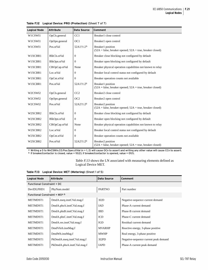
F.21
Date Code 20150130 Instruction Manual SEL-787 Relay
IEC 61850 CommunicationsLogical Nodes
Table F.13 shows the LN associated with measuring elements defined as Logical Device MET.
W1CSWI1 OpCls.general CC1 Breaker1 close control
W1CSWI1 OpOpn.general OC1 Breaker1 open control
W1CSWI1 Pos.stVal 52A1?1:2b Breaker1 position (52A = false, breaker opened; 52A = true, breaker closed)
W1XCBR1 BlkCls.stVal 0 Breaker close blocking not configured by default
W1XCBR1 BlkOpn.stVal 0 Breaker open blocking not configured by default
W1XCBR1 CBOpCap.stVal None Breaker physical operation capabilities not known to relay
W1XCBR1 Loc.stVal 0 Breaker local control status not configured by default
W1XCBR1 OpCnt.stVal 0 Breaker operation counts not available
W1XCBR1 Pos.stVal 52A1?1:2b Breaker1 position (52A = false, breaker opened; 52A = true, breaker closed)
W2CSWI2 OpCls.general CC2 Breaker2 close control
W2CSWI2 OpOpn.general OC2 Breaker2 open control
W2CSWI2 Pos.stVal 52A2?1:2b Breaker2 position (52A = false, breaker opened; 52A = true, breaker closed)
W2XCBR2 BlkCls.stVal 0 Breaker close blocking not configured by default
W2XCBR2 BlkOpn.stVal 0 Breaker open blocking not configured by default
W2XCBR2 CBOpCap.stVal None Breaker physical operation capabilities not known to relay
W2XCBR2 Loc.stVal 0 Breaker local control status not configured by default
W2XCBR2 OpCnt.stVal 0 Breaker operation counts not available
W2XCBR2 Pos.stVal 52A2?1:2b Breaker2 position (52A = false, breaker opened; 52A = true, breaker closed)
a Writing a 0 to WnCSWIn.CO.Pos.Oper.ctlVal (n = 1, 2) will cause OCn to assert and writing any other value will cause CCn to assert.b If breaker/contactor is closed, value = 10(2); if breaker/contactor is opened, value = 01(1).
Table F.12 Logical Device: PRO (Protection) (Sheet 7 of 7)
Logical Node Attribute Data Source Comment
Table F.13 Logical Device: MET (Metering) (Sheet 1 of 5)
Logical Node Attribute Data Source Comment
Functional Constraint = DC
DevIDLPHD1 PhyNam.model PARTNO Part number
Functional Constraint = MXa b
METMDST1 DmdA.nseq.instCVal.mag.f 3I2D Negative-sequence current demand
METMDST1 DmdA.phsA.instCVal.mag.f IAD Phase-A current demand
METMDST1 DmdA.phsB.instCVal.mag.f IBD Phase-B current demand
METMDST1 DmdA.phsC.instCVal.mag.f ICD Phase-C current demand
METMDST1 DmdA.res.instCVal.mag.f IGD Residual current demand
METMDST1 DmdVArh.instMag.f MVARHP Reactive energy, 3-phase positive
METMDST1 DmdWh.instMag.f MWHP Real energy, 3-phase positive
METMDST1 PkDmdA.nseq.instCVal.mag.f 3I2PD Negative-sequence current peak demand
METMDST1 PkDmdA.phsA.instCVal.mag.f IAPD Phase-A current peak demand
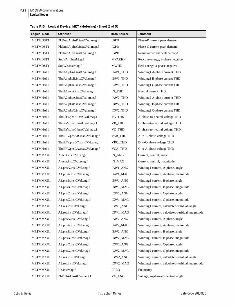
F.22
SEL-787 Relay Instruction Manual Date Code 20150130
IEC 61850 CommunicationsLogical Nodes
METMDST1 PkDmdA.phsB.instCVal.mag.f IBPD Phase-B current peak demand
METMDST1 PkDmdA.phsC.instCVal.mag.f ICPD Phase-C current peak demand
METMDST1 PkDmdA.res.instCVal.mag.f IGPD Residual current peak demand
METMDST1 SupVArh.instMag.f MVARHN Reactive energy, 3-phase negative
METMDST1 SupWh.instMag.f MWHN Real energy, 3-phase negative
METMHAI1 ThdA1.phsA.instCVal.mag.f IAW1_THD Winding1 A-phase current THD
METMHAI1 ThdA1.phsB.instCVal.mag.f IBW1_THD Winding1 B-phase current THD
METMHAI1 ThdA1.phsC.instCVal.mag.f ICW1_THD Winding1 C-phase current THD
METMHAI1 ThdA1.neut.instCVal.mag.f IN_THD Neutral current THD
METMHAI1 ThdA2.phsA.instCVal.mag.f IAW2_THD Winding2 A-phase current THD
METMHAI1 ThdA2.phsB.instCVal.mag.f IBW2_THD Winding2 B-phase current THD
METMHAI1 ThdA2.phsC.instCVal.mag.f ICW2_THD Winding2 C-phase current THD
METMHAI1 ThdPhV.phsA.instCVal.mag.f VA_THD A-phase-to-neutral voltage THD
METMHAI1 ThdPhV.phsB.instCVal.mag.f VB_THD B-phase-to-neutral voltage THD
METMHAI1 ThdPhV.phsC.instCVal.mag.f VC_THD C-phase-to-neutral voltage THD
METMHAI1 ThdPPV.phsAB.instCVal.mag.f VAB_THD A-to-B-phase voltage THD
METMHAI1 ThdPPV.phsBC.instCVal.mag.f VBC_THD B-to-C-phase voltage THD
METMHAI1 ThdPPV.phsCA.instCVal.mag.f VCA_THD C-to-A-phase voltage THD
METMMXU1 A.neut.instCVal.ang.f IN_ANG Current, neutral, angle
METMMXU1 A.neut.instCVal.mag.f IN_MAG Current, neutral, magnitude
METMMXU1 A1.phsA.instCVal.ang.f IAW1_ANG Winding1 current, A-phase, angle
METMMXU1 A1.phsA.instCVal.mag.f IAW1_MAG Winding1 current, A-phase, magnitude
METMMXU1 A1.phsB.instCVal.ang.f IBW1_ANG Winding1 current, B-phase, angle
METMMXU1 A1.phsB.instCVal.mag.f IBW1_MAG Winding1 current, B-phase, magnitude
METMMXU1 A1.phsC.instCVal.ang.f ICW1_ANG Winding1 current, C-phase, angle
METMMXU1 A1.phsC.instCVal.mag.f ICW1_MAG Winding1 current, C-phase, magnitude
METMMXU1 A1.res.instCVal.ang.f IGW1_ANG Winding1 current, calculated-residual, angle
METMMXU1 A1.res.instCVal.mag.f IGW1_MAG Winding1 current, calculated-residual, magnitude
METMMXU1 A2.phsA.instCVal.ang.f IAW2_ANG Winding2 current, A-phase, angle
METMMXU1 A2.phsA.instCVal.mag.f IAW2_MAG Winding2 current, A-phase, magnitude
METMMXU1 A2.phsB.instCVal.ang.f IBW2_ANG Winding2 current, B-phase, angle
METMMXU1 A2.phsB.instCVal.mag.f IBW2_MAG Winding2 current, B-phase, magnitude
METMMXU1 A2.phsC.instCVal.ang.f ICW2_ANG Winding2 current, C-phase, angle
METMMXU1 A2.phsC.instCVal.mag.f ICW2_MAG Winding2 current, C-phase, magnitude
METMMXU1 A2.res.instCVal.ang.f IGW2_ANG Winding2 current, calculated-residual, angle
METMMXU1 A2.res.instCVal.mag.f IGW2_MAG Winding2 current, calculated-residual, magnitude
METMMXU1 Hz.instMag.f FREQ Frequency
METMMXU1 PhV.phsA.instCVal.ang.f VA_ANG Voltage, A-phase-to-neutral, angle
Table F.13 Logical Device: MET (Metering) (Sheet 2 of 5)
Logical Node Attribute Data Source Comment
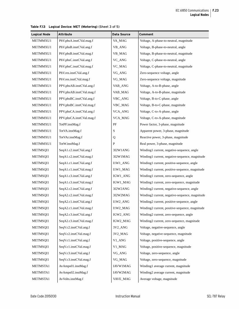
F.23
Date Code 20150130 Instruction Manual SEL-787 Relay
IEC 61850 CommunicationsLogical Nodes
METMMXU1 PhV.phsA.instCVal.mag.f VA_MAG Voltage, A-phase-to-neutral, magnitude
METMMXU1 PhV.phsB.instCVal.ang.f VB_ANG Voltage, B-phase-to-neutral, angle
METMMXU1 PhV.phsB.instCVal.mag.f VB_MAG Voltage, B-phase-to-neutral, magnitude
METMMXU1 PhV.phsC.instCVal.ang.f VC_ANG Voltage, C-phase-to-neutral, angle
METMMXU1 PhV.phsC.instCVal.mag.f VC_MAG Voltage, C-phase-to-neutral, magnitude
METMMXU1 PhV.res.instCVal.ang.f VG_ANG Zero-sequence voltage, angle
METMMXU1 PhV.res.instCVal.mag.f VG_MAG Zero-sequence voltage, magnitude
METMMXU1 PPV.phsAB.instCVal.ang.f VAB_ANG Voltage, A-to-B-phase, angle
METMMXU1 PPV.phsAB.instCVal.mag.f VAB_MAG Voltage, A-to-B-phase, magnitude
METMMXU1 PPV.phsBC.instCVal.ang.f VBC_ANG Voltage, B-to-C-phase, angle
METMMXU1 PPV.phsBC.instCVal.mag.f VBC_MAG Voltage, B-to-C-phase, magnitude
METMMXU1 PPV.phsCA.instCVal.ang.f VCA_ANG Voltage, C-to-A-phase, angle
METMMXU1 PPV.phsCA.instCVal.mag.f VCA_MAG Voltage, C-to-A-phase, magnitude
METMMXU1 TotPF.instMag.f PF Power factor, 3-phase, magnitude
METMMXU1 TotVA.instMag.f S Apparent power, 3-phase, magnitude
METMMXU1 TotVAr.instMag.f Q Reactive power, 3-phase, magnitude
METMMXU1 TotW.instMag.f P Real power, 3-phase, magnitude
METMSQI1 SeqA1.c2.instCVal.ang.f 3I2W1ANG Winding1 current, negative-sequence, angle
METMSQI1 SeqA1.c2.instCVal.mag.f 3I2W1MAG Winding1 current, negative-sequence, magnitude
METMSQI1 SeqA1.c1.instCVal.ang.f I1W1_ANG Winding1 current, positive-sequence, angle
METMSQI1 SeqA1.c1.instCVal.mag.f I1W1_MAG Winding1 current, positive-sequence, magnitude
METMSQI1 SeqA1.c3.instCVal.ang.f IGW1_ANG Winding1 current, zero-sequence, angle
METMSQI1 SeqA1.c3.instCVal.mag.f IGW1_MAG Winding1 current, zero-sequence, magnitude
METMSQI1 SeqA2.c2.instCVal.ang.f 3I2W2ANG Winding2 current, negative-sequence, angle
METMSQI1 SeqA2.c2.instCVal.mag.f 3I2W2MAG Winding2 current, negative-sequence, magnitude
METMSQI1 SeqA2.c1.instCVal.ang.f I1W2_ANG Winding2 current, positive-sequence, angle
METMSQI1 SeqA2.c1.instCVal.mag.f I1W2_MAG Winding2 current, positive-sequence, magnitude
METMSQI1 SeqA2.c3.instCVal.ang.f IGW2_ANG Winding2 current, zero-sequence, angle
METMSQI1 SeqA2.c3.instCVal.mag.f IGW2_MAG Winding2 current, zero-sequence, magnitude
METMSQI1 SeqV.c2.instCVal.ang.f 3V2_ANG Voltage, negative-sequence, angle
METMSQI1 SeqV.c2.instCVal.mag.f 3V2_MAG Voltage, negative-sequence, magnitude
METMSQI1 SeqV.c1.instCVal.ang.f V1_ANG Voltage, positive-sequence, angle
METMSQI1 SeqV.c1.instCVal.mag.f V1_MAG Voltage, positive-sequence, magnitude
METMSQI1 SeqV.c3.instCVal.ang.f VG_ANG Voltage, zero-sequence, angle
METMSQI1 SeqV.c3.instCVal.mag.f VG_MAG Voltage, zero-sequence, magnitude
METMSTA1 AvAmps01.instMag.f IAVW1MAG Winding1 average current, magnitude
METMSTA1 AvAmps02.instMag.f IAVW2MAG Winding2 average current, magnitude
METMSTA1 AvVolts.instMag.f VAVE_MAG Average voltage, magnitude
Table F.13 Logical Device: MET (Metering) (Sheet 3 of 5)
Logical Node Attribute Data Source Comment
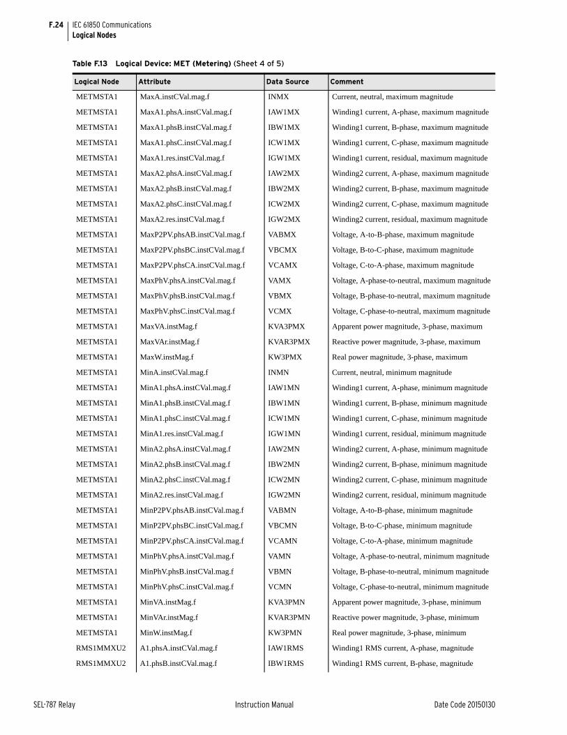
F.24
SEL-787 Relay Instruction Manual Date Code 20150130
IEC 61850 CommunicationsLogical Nodes
METMSTA1 MaxA.instCVal.mag.f INMX Current, neutral, maximum magnitude
METMSTA1 MaxA1.phsA.instCVal.mag.f IAW1MX Winding1 current, A-phase, maximum magnitude
METMSTA1 MaxA1.phsB.instCVal.mag.f IBW1MX Winding1 current, B-phase, maximum magnitude
METMSTA1 MaxA1.phsC.instCVal.mag.f ICW1MX Winding1 current, C-phase, maximum magnitude
METMSTA1 MaxA1.res.instCVal.mag.f IGW1MX Winding1 current, residual, maximum magnitude
METMSTA1 MaxA2.phsA.instCVal.mag.f IAW2MX Winding2 current, A-phase, maximum magnitude
METMSTA1 MaxA2.phsB.instCVal.mag.f IBW2MX Winding2 current, B-phase, maximum magnitude
METMSTA1 MaxA2.phsC.instCVal.mag.f ICW2MX Winding2 current, C-phase, maximum magnitude
METMSTA1 MaxA2.res.instCVal.mag.f IGW2MX Winding2 current, residual, maximum magnitude
METMSTA1 MaxP2PV.phsAB.instCVal.mag.f VABMX Voltage, A-to-B-phase, maximum magnitude
METMSTA1 MaxP2PV.phsBC.instCVal.mag.f VBCMX Voltage, B-to-C-phase, maximum magnitude
METMSTA1 MaxP2PV.phsCA.instCVal.mag.f VCAMX Voltage, C-to-A-phase, maximum magnitude
METMSTA1 MaxPhV.phsA.instCVal.mag.f VAMX Voltage, A-phase-to-neutral, maximum magnitude
METMSTA1 MaxPhV.phsB.instCVal.mag.f VBMX Voltage, B-phase-to-neutral, maximum magnitude
METMSTA1 MaxPhV.phsC.instCVal.mag.f VCMX Voltage, C-phase-to-neutral, maximum magnitude
METMSTA1 MaxVA.instMag.f KVA3PMX Apparent power magnitude, 3-phase, maximum
METMSTA1 MaxVAr.instMag.f KVAR3PMX Reactive power magnitude, 3-phase, maximum
METMSTA1 MaxW.instMag.f KW3PMX Real power magnitude, 3-phase, maximum
METMSTA1 MinA.instCVal.mag.f INMN Current, neutral, minimum magnitude
METMSTA1 MinA1.phsA.instCVal.mag.f IAW1MN Winding1 current, A-phase, minimum magnitude
METMSTA1 MinA1.phsB.instCVal.mag.f IBW1MN Winding1 current, B-phase, minimum magnitude
METMSTA1 MinA1.phsC.instCVal.mag.f ICW1MN Winding1 current, C-phase, minimum magnitude
METMSTA1 MinA1.res.instCVal.mag.f IGW1MN Winding1 current, residual, minimum magnitude
METMSTA1 MinA2.phsA.instCVal.mag.f IAW2MN Winding2 current, A-phase, minimum magnitude
METMSTA1 MinA2.phsB.instCVal.mag.f IBW2MN Winding2 current, B-phase, minimum magnitude
METMSTA1 MinA2.phsC.instCVal.mag.f ICW2MN Winding2 current, C-phase, minimum magnitude
METMSTA1 MinA2.res.instCVal.mag.f IGW2MN Winding2 current, residual, minimum magnitude
METMSTA1 MinP2PV.phsAB.instCVal.mag.f VABMN Voltage, A-to-B-phase, minimum magnitude
METMSTA1 MinP2PV.phsBC.instCVal.mag.f VBCMN Voltage, B-to-C-phase, minimum magnitude
METMSTA1 MinP2PV.phsCA.instCVal.mag.f VCAMN Voltage, C-to-A-phase, minimum magnitude
METMSTA1 MinPhV.phsA.instCVal.mag.f VAMN Voltage, A-phase-to-neutral, minimum magnitude
METMSTA1 MinPhV.phsB.instCVal.mag.f VBMN Voltage, B-phase-to-neutral, minimum magnitude
METMSTA1 MinPhV.phsC.instCVal.mag.f VCMN Voltage, C-phase-to-neutral, minimum magnitude
METMSTA1 MinVA.instMag.f KVA3PMN Apparent power magnitude, 3-phase, minimum
METMSTA1 MinVAr.instMag.f KVAR3PMN Reactive power magnitude, 3-phase, minimum
METMSTA1 MinW.instMag.f KW3PMN Real power magnitude, 3-phase, minimum
RMS1MMXU2 A1.phsA.instCVal.mag.f IAW1RMS Winding1 RMS current, A-phase, magnitude
RMS1MMXU2 A1.phsB.instCVal.mag.f IBW1RMS Winding1 RMS current, B-phase, magnitude
Table F.13 Logical Device: MET (Metering) (Sheet 4 of 5)
Logical Node Attribute Data Source Comment
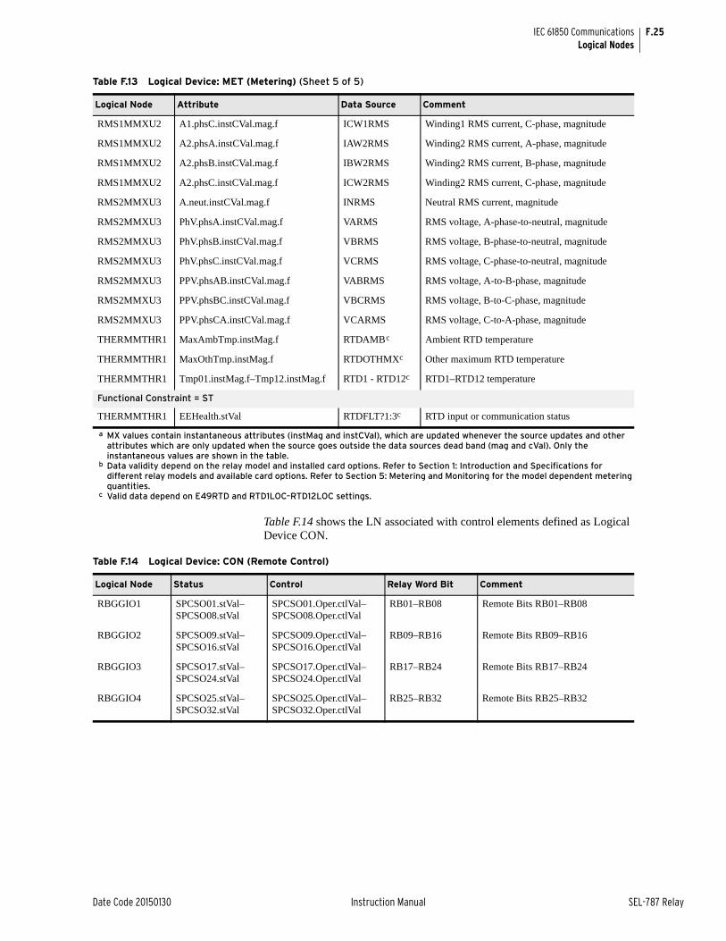
F.25
Date Code 20150130 Instruction Manual SEL-787 Relay
IEC 61850 CommunicationsLogical Nodes
Table F.14 shows the LN associated with control elements defined as Logical Device CON.
RMS1MMXU2 A1.phsC.instCVal.mag.f ICW1RMS Winding1 RMS current, C-phase, magnitude
RMS1MMXU2 A2.phsA.instCVal.mag.f IAW2RMS Winding2 RMS current, A-phase, magnitude
RMS1MMXU2 A2.phsB.instCVal.mag.f IBW2RMS Winding2 RMS current, B-phase, magnitude
RMS1MMXU2 A2.phsC.instCVal.mag.f ICW2RMS Winding2 RMS current, C-phase, magnitude
RMS2MMXU3 A.neut.instCVal.mag.f INRMS Neutral RMS current, magnitude
RMS2MMXU3 PhV.phsA.instCVal.mag.f VARMS RMS voltage, A-phase-to-neutral, magnitude
RMS2MMXU3 PhV.phsB.instCVal.mag.f VBRMS RMS voltage, B-phase-to-neutral, magnitude
RMS2MMXU3 PhV.phsC.instCVal.mag.f VCRMS RMS voltage, C-phase-to-neutral, magnitude
RMS2MMXU3 PPV.phsAB.instCVal.mag.f VABRMS RMS voltage, A-to-B-phase, magnitude
RMS2MMXU3 PPV.phsBC.instCVal.mag.f VBCRMS RMS voltage, B-to-C-phase, magnitude
RMS2MMXU3 PPV.phsCA.instCVal.mag.f VCARMS RMS voltage, C-to-A-phase, magnitude
THERMMTHR1 MaxAmbTmp.instMag.f RTDAMBc Ambient RTD temperature
THERMMTHR1 MaxOthTmp.instMag.f RTDOTHMXc Other maximum RTD temperature
THERMMTHR1 Tmp01.instMag.f–Tmp12.instMag.f RTD1 - RTD12c RTD1–RTD12 temperature
Functional Constraint = ST
THERMMTHR1 EEHealth.stVal RTDFLT?1:3c RTD input or communication status
a MX values contain instantaneous attributes (instMag and instCVal), which are updated whenever the source updates and other attributes which are only updated when the source goes outside the data sources dead band (mag and cVal). Only the instantaneous values are shown in the table.
b Data validity depend on the relay model and installed card options. Refer to Section 1: Introduction and Specifications for different relay models and available card options. Refer to Section 5: Metering and Monitoring for the model dependent metering quantities.
c Valid data depend on E49RTD and RTD1LOC–RTD12LOC settings.
Table F.13 Logical Device: MET (Metering) (Sheet 5 of 5)
Logical Node Attribute Data Source Comment
Table F.14 Logical Device: CON (Remote Control)
Logical Node Status Control Relay Word Bit Comment
RBGGIO1 SPCSO01.stVal–SPCSO08.stVal
SPCSO01.Oper.ctlVal–SPCSO08.Oper.ctlVal
RB01–RB08 Remote Bits RB01–RB08
RBGGIO2 SPCSO09.stVal–SPCSO16.stVal
SPCSO09.Oper.ctlVal–SPCSO16.Oper.ctlVal
RB09–RB16 Remote Bits RB09–RB16
RBGGIO3 SPCSO17.stVal–SPCSO24.stVal
SPCSO17.Oper.ctlVal–SPCSO24.Oper.ctlVal
RB17–RB24 Remote Bits RB17–RB24
RBGGIO4 SPCSO25.stVal–SPCSO32.stVal
SPCSO25.Oper.ctlVal–SPCSO32.Oper.ctlVal
RB25–RB32 Remote Bits RB25–RB32
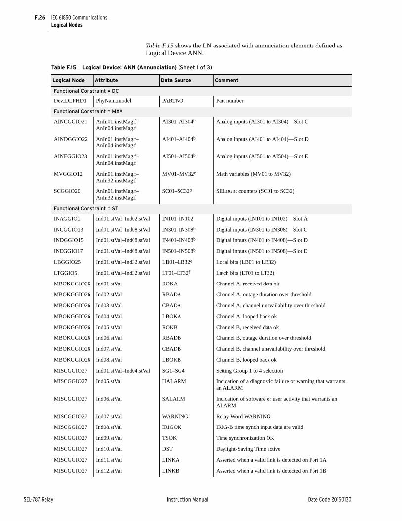
F.26
SEL-787 Relay Instruction Manual Date Code 20150130
IEC 61850 CommunicationsLogical Nodes
Table F.15 shows the LN associated with annunciation elements defined as Logical Device ANN.
Table F.15 Logical Device: ANN (Annunciation) (Sheet 1 of 3)
Logical Node Attribute Data Source Comment
Functional Constraint = DC
DevIDLPHD1 PhyNam.model PARTNO Part number
Functional Constraint = MXa
AINCGGIO21 AnIn01.instMag.f–AnIn04.instMag.f
AI301–AI304b Analog inputs (AI301 to AI304)—Slot C
AINDGGIO22 AnIn01.instMag.f–AnIn04.instMag.f
AI401–AI404b Analog inputs (AI401 to AI404)—Slot D
AINEGGIO23 AnIn01.instMag.f–AnIn04.instMag.f
AI501–AI504b Analog inputs (AI501 to AI504)—Slot E
MVGGIO12 AnIn01.instMag.f–AnIn32.instMag.f
MV01–MV32c Math variables (MV01 to MV32)
SCGGIO20 AnIn01.instMag.f–AnIn32.instMag.f
SC01–SC32d SELOGIC counters (SC01 to SC32)
Functional Constraint = ST
INAGGIO1 Ind01.stVal–Ind02.stVal IN101–IN102 Digital inputs (IN101 to IN102)—Slot A
INCGGIO13 Ind01.stVal–Ind08.stVal IN301–IN308b Digital inputs (IN301 to IN308)—Slot C
INDGGIO15 Ind01.stVal–Ind08.stVal IN401–IN408b Digital inputs (IN401 to IN408)—Slot D
INEGGIO17 Ind01.stVal–Ind08.stVal IN501–IN508b Digital inputs (IN501 to IN508)—Slot E
LBGGIO25 Ind01.stVal–Ind32.stVal LB01–LB32e Local bits (LB01 to LB32)
LTGGIO5 Ind01.stVal–Ind32.stVal LT01–LT32f Latch bits (LT01 to LT32)
MBOKGGIO26 Ind01.stVal ROKA Channel A, received data ok
MBOKGGIO26 Ind02.stVal RBADA Channel A, outage duration over threshold
MBOKGGIO26 Ind03.stVal CBADA Channel A, channel unavailability over threshold
MBOKGGIO26 Ind04.stVal LBOKA Channel A, looped back ok
MBOKGGIO26 Ind05.stVal ROKB Channel B, received data ok
MBOKGGIO26 Ind06.stVal RBADB Channel B, outage duration over threshold
MBOKGGIO26 Ind07.stVal CBADB Channel B, channel unavailability over threshold
MBOKGGIO26 Ind08.stVal LBOKB Channel B, looped back ok
MISCGGIO27 Ind01.stVal–Ind04.stVal SG1–SG4 Setting Group 1 to 4 selection
MISCGGIO27 Ind05.stVal HALARM Indication of a diagnostic failure or warning that warrants an ALARM
MISCGGIO27 Ind06.stVal SALARM Indication of software or user activity that warrants an ALARM
MISCGGIO27 Ind07.stVal WARNING Relay Word WARNING
MISCGGIO27 Ind08.stVal IRIGOK IRIG-B time synch input data are valid
MISCGGIO27 Ind09.stVal TSOK Time synchronization OK
MISCGGIO27 Ind10.stVal DST Daylight-Saving Time active
MISCGGIO27 Ind11.stVal LINKA Asserted when a valid link is detected on Port 1A
MISCGGIO27 Ind12.stVal LINKB Asserted when a valid link is detected on Port 1B
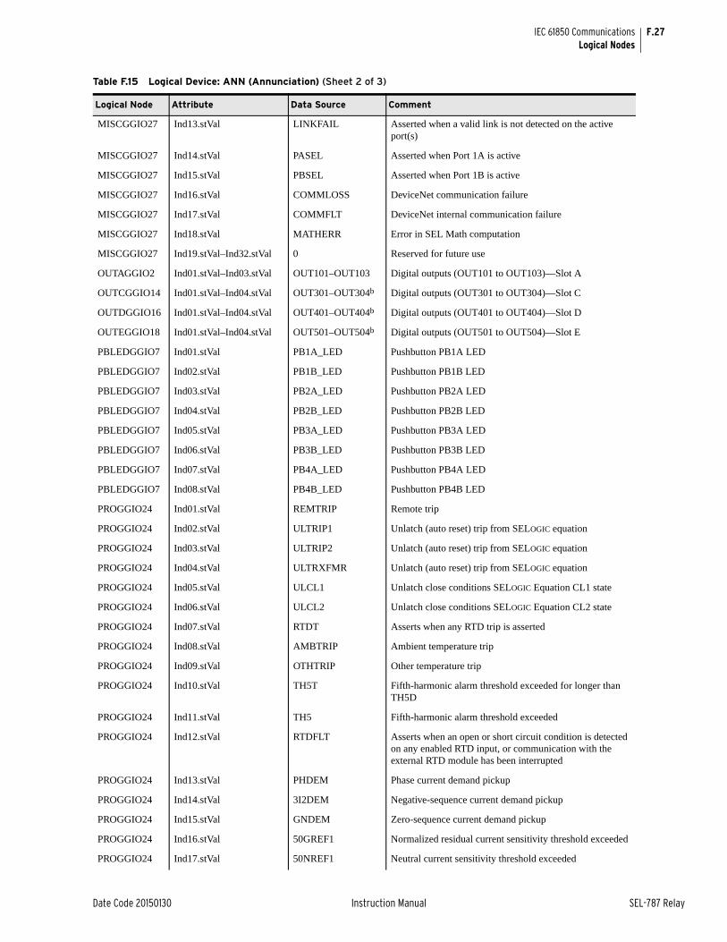
F.27
Date Code 20150130 Instruction Manual SEL-787 Relay
IEC 61850 CommunicationsLogical Nodes
MISCGGIO27 Ind13.stVal LINKFAIL Asserted when a valid link is not detected on the active port(s)
MISCGGIO27 Ind14.stVal PASEL Asserted when Port 1A is active
MISCGGIO27 Ind15.stVal PBSEL Asserted when Port 1B is active
MISCGGIO27 Ind16.stVal COMMLOSS DeviceNet communication failure
MISCGGIO27 Ind17.stVal COMMFLT DeviceNet internal communication failure
MISCGGIO27 Ind18.stVal MATHERR Error in SEL Math computation
MISCGGIO27 Ind19.stVal–Ind32.stVal 0 Reserved for future use
OUTAGGIO2 Ind01.stVal–Ind03.stVal OUT101–OUT103 Digital outputs (OUT101 to OUT103)—Slot A
OUTCGGIO14 Ind01.stVal–Ind04.stVal OUT301–OUT304b Digital outputs (OUT301 to OUT304)—Slot C
OUTDGGIO16 Ind01.stVal–Ind04.stVal OUT401–OUT404b Digital outputs (OUT401 to OUT404)—Slot D
OUTEGGIO18 Ind01.stVal–Ind04.stVal OUT501–OUT504b Digital outputs (OUT501 to OUT504)—Slot E
PBLEDGGIO7 Ind01.stVal PB1A_LED Pushbutton PB1A LED
PBLEDGGIO7 Ind02.stVal PB1B_LED Pushbutton PB1B LED
PBLEDGGIO7 Ind03.stVal PB2A_LED Pushbutton PB2A LED
PBLEDGGIO7 Ind04.stVal PB2B_LED Pushbutton PB2B LED
PBLEDGGIO7 Ind05.stVal PB3A_LED Pushbutton PB3A LED
PBLEDGGIO7 Ind06.stVal PB3B_LED Pushbutton PB3B LED
PBLEDGGIO7 Ind07.stVal PB4A_LED Pushbutton PB4A LED
PBLEDGGIO7 Ind08.stVal PB4B_LED Pushbutton PB4B LED
PROGGIO24 Ind01.stVal REMTRIP Remote trip
PROGGIO24 Ind02.stVal ULTRIP1 Unlatch (auto reset) trip from SELOGIC equation
PROGGIO24 Ind03.stVal ULTRIP2 Unlatch (auto reset) trip from SELOGIC equation
PROGGIO24 Ind04.stVal ULTRXFMR Unlatch (auto reset) trip from SELOGIC equation
PROGGIO24 Ind05.stVal ULCL1 Unlatch close conditions SELOGIC Equation CL1 state
PROGGIO24 Ind06.stVal ULCL2 Unlatch close conditions SELOGIC Equation CL2 state
PROGGIO24 Ind07.stVal RTDT Asserts when any RTD trip is asserted
PROGGIO24 Ind08.stVal AMBTRIP Ambient temperature trip
PROGGIO24 Ind09.stVal OTHTRIP Other temperature trip
PROGGIO24 Ind10.stVal TH5T Fifth-harmonic alarm threshold exceeded for longer than TH5D
PROGGIO24 Ind11.stVal TH5 Fifth-harmonic alarm threshold exceeded
PROGGIO24 Ind12.stVal RTDFLT Asserts when an open or short circuit condition is detected on any enabled RTD input, or communication with the external RTD module has been interrupted
PROGGIO24 Ind13.stVal PHDEM Phase current demand pickup
PROGGIO24 Ind14.stVal 3I2DEM Negative-sequence current demand pickup
PROGGIO24 Ind15.stVal GNDEM Zero-sequence current demand pickup
PROGGIO24 Ind16.stVal 50GREF1 Normalized residual current sensitivity threshold exceeded
PROGGIO24 Ind17.stVal 50NREF1 Neutral current sensitivity threshold exceeded
Table F.15 Logical Device: ANN (Annunciation) (Sheet 2 of 3)
Logical Node Attribute Data Source Comment
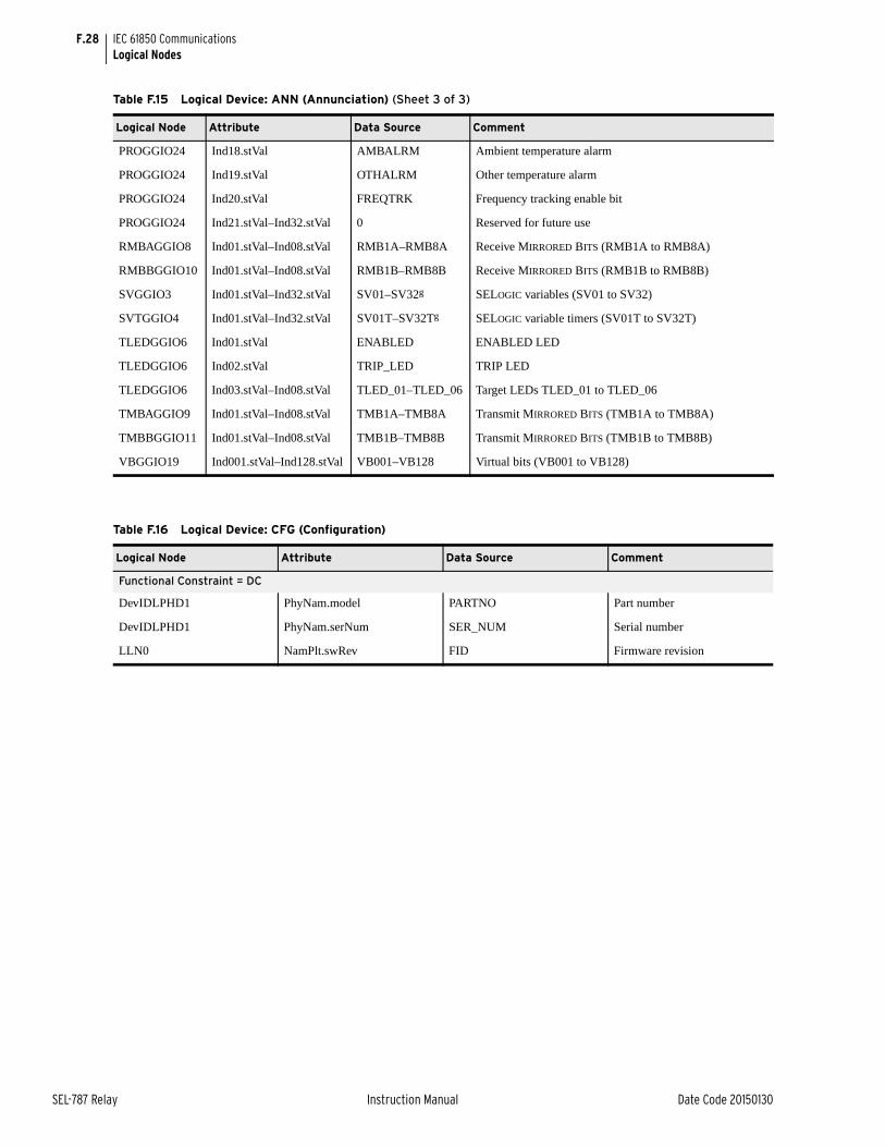
F.28
SEL-787 Relay Instruction Manual Date Code 20150130
IEC 61850 CommunicationsLogical Nodes
PROGGIO24 Ind18.stVal AMBALRM Ambient temperature alarm
PROGGIO24 Ind19.stVal OTHALRM Other temperature alarm
PROGGIO24 Ind20.stVal FREQTRK Frequency tracking enable bit
PROGGIO24 Ind21.stVal–Ind32.stVal 0 Reserved for future use
RMBAGGIO8 Ind01.stVal–Ind08.stVal RMB1A–RMB8A Receive MIRRORED BITS (RMB1A to RMB8A)
RMBBGGIO10 Ind01.stVal–Ind08.stVal RMB1B–RMB8B Receive MIRRORED BITS (RMB1B to RMB8B)
SVGGIO3 Ind01.stVal–Ind32.stVal SV01–SV32g SELOGIC variables (SV01 to SV32)
SVTGGIO4 Ind01.stVal–Ind32.stVal SV01T–SV32Tg SELOGIC variable timers (SV01T to SV32T)
TLEDGGIO6 Ind01.stVal ENABLED ENABLED LED
TLEDGGIO6 Ind02.stVal TRIP_LED TRIP LED
TLEDGGIO6 Ind03.stVal–Ind08.stVal TLED_01–TLED_06 Target LEDs TLED_01 to TLED_06
TMBAGGIO9 Ind01.stVal–Ind08.stVal TMB1A–TMB8A Transmit MIRRORED BITS (TMB1A to TMB8A)
TMBBGGIO11 Ind01.stVal–Ind08.stVal TMB1B–TMB8B Transmit MIRRORED BITS (TMB1B to TMB8B)
VBGGIO19 Ind001.stVal–Ind128.stVal VB001–VB128 Virtual bits (VB001 to VB128)
Table F.15 Logical Device: ANN (Annunciation) (Sheet 3 of 3)
Logical Node Attribute Data Source Comment
Table F.16 Logical Device: CFG (Configuration)
Logical Node Attribute Data Source Comment
Functional Constraint = DC
DevIDLPHD1 PhyNam.model PARTNO Part number
DevIDLPHD1 PhyNam.serNum SER_NUM Serial number
LLN0 NamPlt.swRev FID Firmware revision
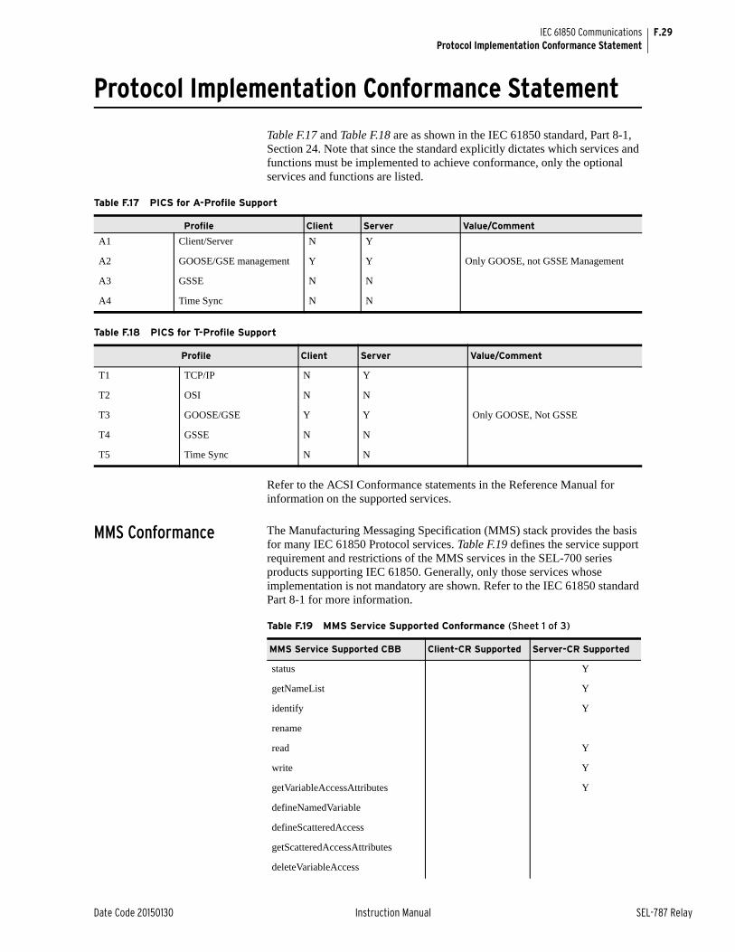
F.29
Date Code 20150130 Instruction Manual SEL-787 Relay
IEC 61850 CommunicationsProtocol Implementation Conformance Statement
Protocol Implementation Conformance Statement
Table F.17 and Table F.18 are as shown in the IEC 61850 standard, Part 8-1, Section 24. Note that since the standard explicitly dictates which services and functions must be implemented to achieve conformance, only the optional services and functions are listed.
Refer to the ACSI Conformance statements in the Reference Manual for information on the supported services.
MMS Conformance The Manufacturing Messaging Specification (MMS) stack provides the basis for many IEC 61850 Protocol services. Table F.19 defines the service support requirement and restrictions of the MMS services in the SEL-700 series products supporting IEC 61850. Generally, only those services whose implementation is not mandatory are shown. Refer to the IEC 61850 standard Part 8-1 for more information.
Table F.17 PICS for A-Profile Support
Profile Client Server Value/Comment
A1 Client/Server N Y
A2 GOOSE/GSE management Y Y Only GOOSE, not GSSE Management
A3 GSSE N N
A4 Time Sync N N
Table F.18 PICS for T-Profile Support
Profile Client Server Value/Comment
T1 TCP/IP N Y
T2 OSI N N
T3 GOOSE/GSE Y Y Only GOOSE, Not GSSE
T4 GSSE N N
T5 Time Sync N N
Table F.19 MMS Service Supported Conformance (Sheet 1 of 3)
MMS Service Supported CBB Client-CR Supported Server-CR Supported
status Y
getNameList Y
identify Y
rename
read Y
write Y
getVariableAccessAttributes Y
defineNamedVariable
defineScatteredAccess
getScatteredAccessAttributes
deleteVariableAccess
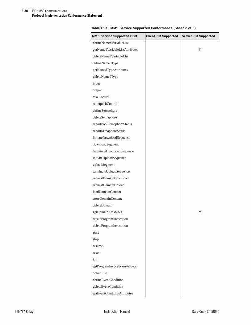
F.30
SEL-787 Relay Instruction Manual Date Code 20150130
IEC 61850 CommunicationsProtocol Implementation Conformance Statement
defineNamedVariableList
getNamedVariableListAttributes Y
deleteNamedVariableList
defineNamedType
getNamedTypeAttributes
deleteNamedType
input
output
takeControl
relinquishControl
defineSemaphore
deleteSemaphore
reportPoolSemaphoreStatus
reportSemaphoreStatus
initiateDownloadSequence
downloadSegment
terminateDownloadSequence
initiateUploadSequence
uploadSegment
terminateUploadSequence
requestDomainDownload
requestDomainUpload
loadDomainContent
storeDomainContent
deleteDomain
getDomainAttributes Y
createProgramInvocation
deleteProgramInvocation
start
stop
resume
reset
kill
getProgramInvocationAttributes
obtainFile
defineEventCondition
deleteEventCondition
getEventConditionAttributes
Table F.19 MMS Service Supported Conformance (Sheet 2 of 3)
MMS Service Supported CBB Client-CR Supported Server-CR Supported
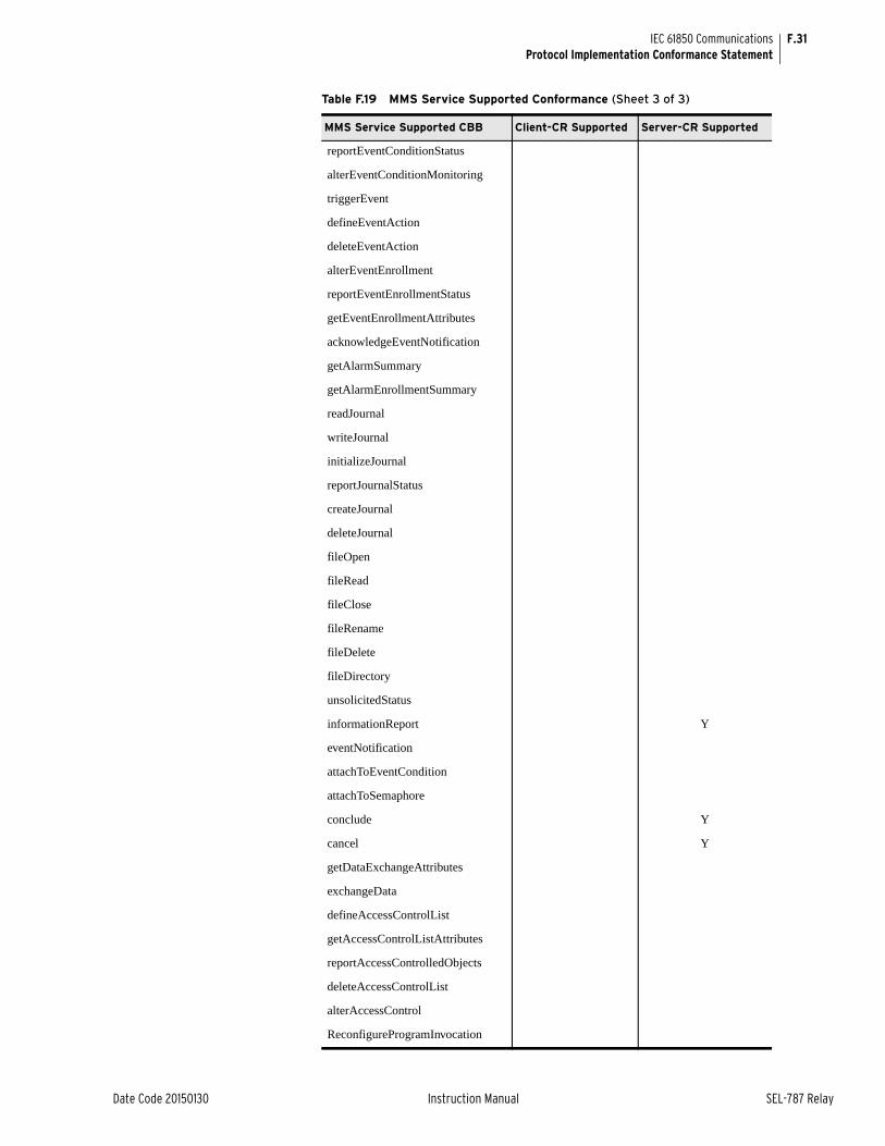
F.31
Date Code 20150130 Instruction Manual SEL-787 Relay
IEC 61850 CommunicationsProtocol Implementation Conformance Statement
reportEventConditionStatus
alterEventConditionMonitoring
triggerEvent
defineEventAction
deleteEventAction
alterEventEnrollment
reportEventEnrollmentStatus
getEventEnrollmentAttributes
acknowledgeEventNotification
getAlarmSummary
getAlarmEnrollmentSummary
readJournal
writeJournal
initializeJournal
reportJournalStatus
createJournal
deleteJournal
fileOpen
fileRead
fileClose
fileRename
fileDelete
fileDirectory
unsolicitedStatus
informationReport Y
eventNotification
attachToEventCondition
attachToSemaphore
conclude Y
cancel Y
getDataExchangeAttributes
exchangeData
defineAccessControlList
getAccessControlListAttributes
reportAccessControlledObjects
deleteAccessControlList
alterAccessControl
ReconfigureProgramInvocation
Table F.19 MMS Service Supported Conformance (Sheet 3 of 3)
MMS Service Supported CBB Client-CR Supported Server-CR Supported

F.32
SEL-787 Relay Instruction Manual Date Code 20150130
IEC 61850 CommunicationsProtocol Implementation Conformance Statement
Table F.20 lists specific settings for the MMS parameter Conformance Building Block (CBB).
The following Variable Access Conformance Statements (Table F.21 through Table F.28) are listed in the order specified in the IEC 61850 standard, Part 8-1. Generally, only those services whose implementation is not mandatory are shown. Refer to the IEC 61850 standard Part 8-1 for more information.
Table F.20 MMS Parameter CBB
MMS Parameter CBB Client-CR Supported Server-CR Supported
STR1 Y
STR2 Y
VNAM Y
VADR Y
VALT Y
TPY Y
VLIS Y
CEI
Table F.21 Alternate Access Selection Conformance Statement
Alternate Access Selection Client-CR Supported Server-CR Supported
accessSelection Y
component Y
index
indexRange
allElements
alternateAccess Y
selectAccess Y
component Y
index
indexRange
allElements
Table F.22 VariableAccessSpecification Conformance Statement
VariableAccessSpecification Client-CR Supported Server-CR Supported
listOfVariable Y
variableSpecification Y
alternateAccess Y
variableListName Y
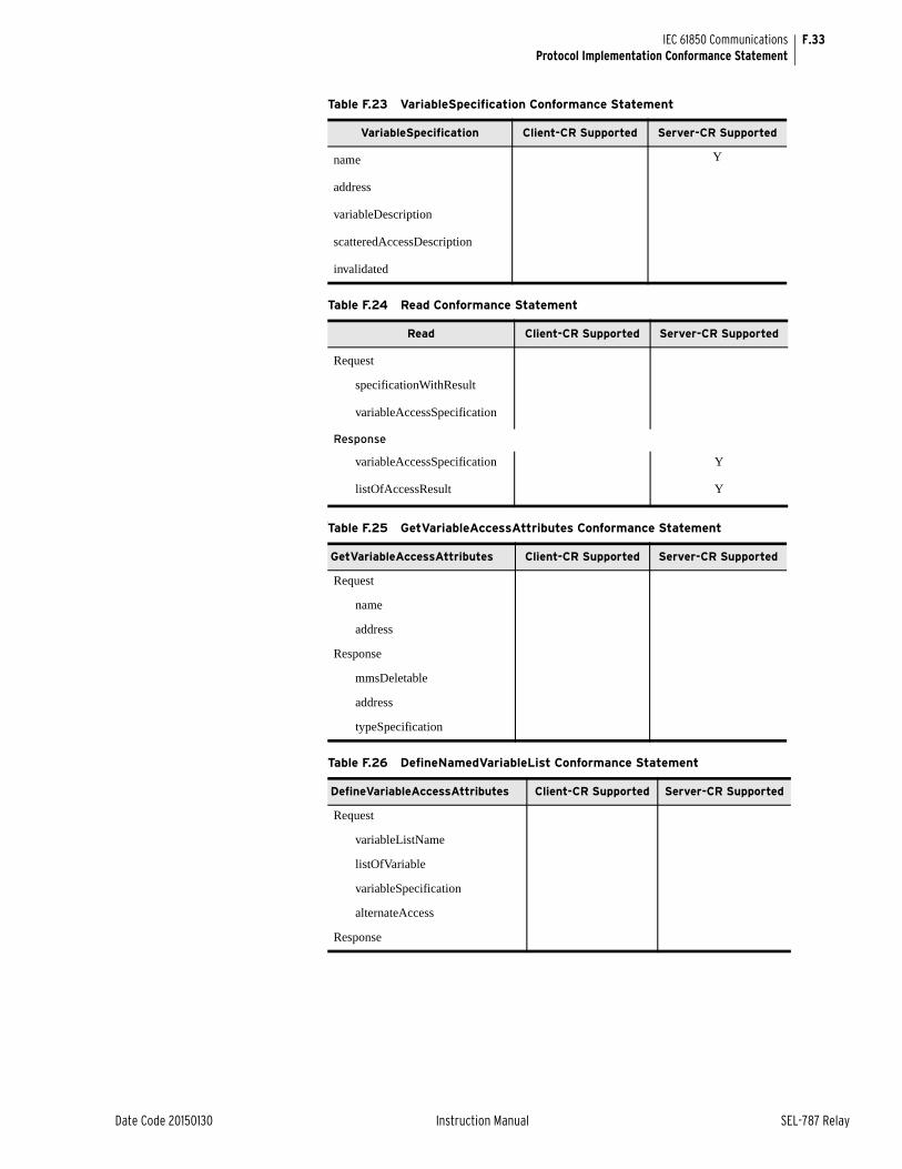
F.33
Date Code 20150130 Instruction Manual SEL-787 Relay
IEC 61850 CommunicationsProtocol Implementation Conformance Statement
t
Table F.23 VariableSpecification Conformance Statement
VariableSpecification Client-CR Supported Server-CR Supported
name Y
address
variableDescription
scatteredAccessDescription
invalidated
Table F.24 Read Conformance Statement
Read Client-CR Supported Server-CR Supported
Request
specificationWithResult
variableAccessSpecification
Response
variableAccessSpecification Y
listOfAccessResult Y
Table F.25 GetVariableAccessAttributes Conformance Statement
GetVariableAccessAttributes Client-CR Supported Server-CR Supported
Request
name
address
Response
mmsDeletable
address
typeSpecification
Table F.26 DefineNamedVariableList Conformance Statement
DefineVariableAccessAttributes Client-CR Supported Server-CR Supported
Request
variableListName
listOfVariable
variableSpecification
alternateAccess
Response
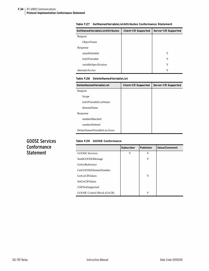
F.34
SEL-787 Relay Instruction Manual Date Code 20150130
IEC 61850 CommunicationsProtocol Implementation Conformance Statement
GOOSE Services Conformance Statement
Table F.27 GetNamedVariableListAttributes Conformance Statement
GetNamedVariableListAttributes Client-CR Supported Server-CR Supported
Request
ObjectName
Response
mmsDeletable Y
listOfVariable Y
variableSpecification Y
alternateAccess Y
Table F.28 DeleteNamedVariableList
DeleteNamedVariableList Client-CR Supported Server-CR Supported
Request
Scope
listOfVariableListName
domainName
Response
numberMatched
numberDeleted
DeleteNamedVariableList-Error
Table F.29 GOOSE Conformance
Subscriber Publisher Value/Comment
GOOSE Services Y Y
SendGOOSEMessage Y
GetGoReference
GetGOOSEElementNumber
GetGoCBValues Y
SetGoCBValues
GSENotSupported
GOOSE Control Block (GoCB) Y
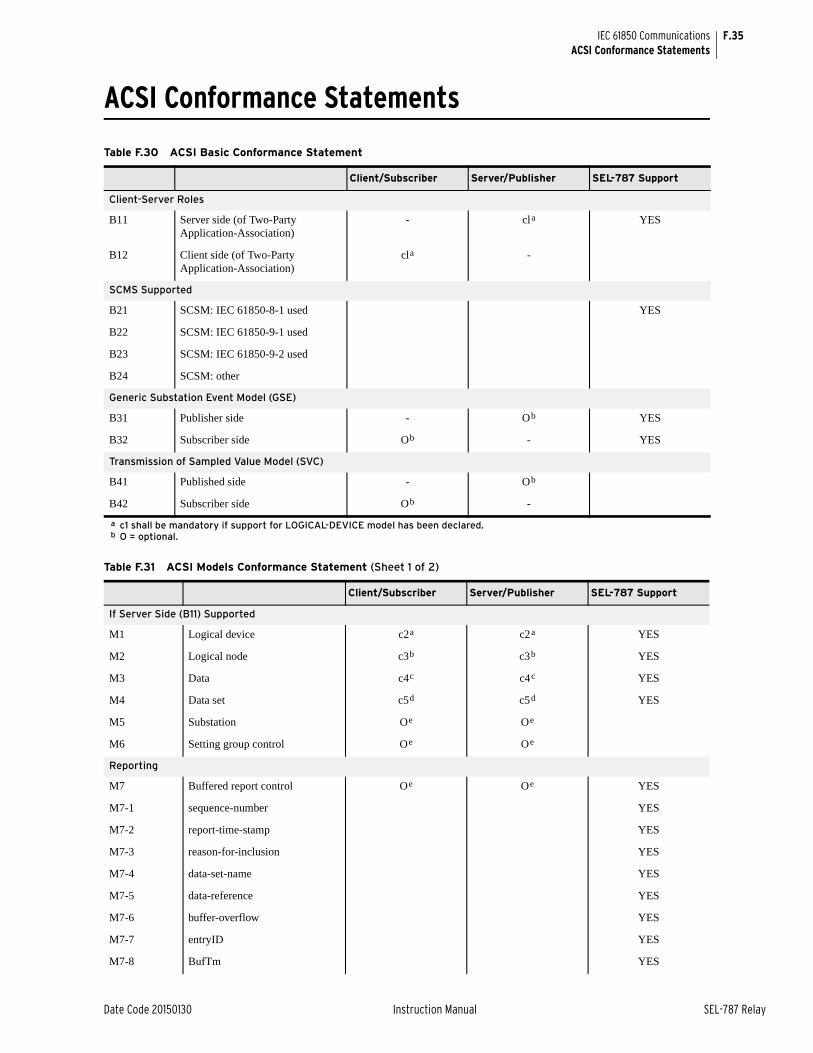
F.35
Date Code 20150130 Instruction Manual SEL-787 Relay
IEC 61850 CommunicationsACSI Conformance Statements
ACSI Conformance Statements
Table F.30 ACSI Basic Conformance Statement
Client/Subscriber Server/Publisher SEL-787 Support
Client-Server Roles
B11 Server side (of Two-Party Application-Association)
- cla YES
B12 Client side (of Two-Party Application-Association)
cla
a c1 shall be mandatory if support for LOGICAL-DEVICE model has been declared.
-
SCMS Supported
B21 SCSM: IEC 61850-8-1 used YES
B22 SCSM: IEC 61850-9-1 used
B23 SCSM: IEC 61850-9-2 used
B24 SCSM: other
Generic Substation Event Model (GSE)
B31 Publisher side - Ob YES
B32 Subscriber side Ob
b O = optional.
- YES
Transmission of Sampled Value Model (SVC)
B41 Published side - Ob
B42 Subscriber side Ob -
Table F.31 ACSI Models Conformance Statement (Sheet 1 of 2)
Client/Subscriber Server/Publisher SEL-787 Support
If Server Side (B11) Supported
M1 Logical device c2a c2a YES
M2 Logical node c3b c3b YES
M3 Data c4c c4c YES
M4 Data set c5d c5d YES
M5 Substation Oe Oe
M6 Setting group control Oe Oe
Reporting
M7 Buffered report control Oe Oe YES
M7-1 sequence-number YES
M7-2 report-time-stamp YES
M7-3 reason-for-inclusion YES
M7-4 data-set-name YES
M7-5 data-reference YES
M7-6 buffer-overflow YES
M7-7 entryID YES
M7-8 BufTm YES

F.36
SEL-787 Relay Instruction Manual Date Code 20150130
IEC 61850 CommunicationsACSI Conformance Statements
M7-9 IntgPd YES
M7-10 G1 YES
M8 Unbuffered report control Oe Oe YES
M8-1 sequence-number YES
M8-2 report-time-stamp YES
M8-3 reason-for-inclusion YES
M8-4 data-set-name YES
M8-5 data-reference YES
M8-6 BufTm YES
M8-7 IntgPd YES
M-8-8 GI YES
Logging Oe Oe
M9 Log control Oe Oe
M9-1 IntgPd
M10 Log Oe Oe
M11 Control Mf Mg YES
If GSE (B31/32) Is Supported
M12 GOOSE Oe Oe YES
M12-1 entryID YES
M12-2 DataReflnc YES
M13 GSSE Oe Oe
If GSE (B41/42) Is Supported
M14 Multicast SVC Oe Oe
M15 Unicast SVC Oe Oe
M16 Time Mf Mf
M17 File Transfer Oe Oe
a c2 shall be “M” if support for LOGICAL-NODE model has been declared.b c3 shall be “M” if support for DATA model has been declared.c c4 shall be “M” if support for DATA-SET, Substitution, Report, Log Control, or Time model has been declared.d c5 shall be “M” if support for Report, GSE, or SV models has been declared.e O = Optional.f M = Mandatory.g M = Mandatory.
Table F.31 ACSI Models Conformance Statement (Sheet 2 of 2)
Client/Subscriber Server/Publisher SEL-787 Support
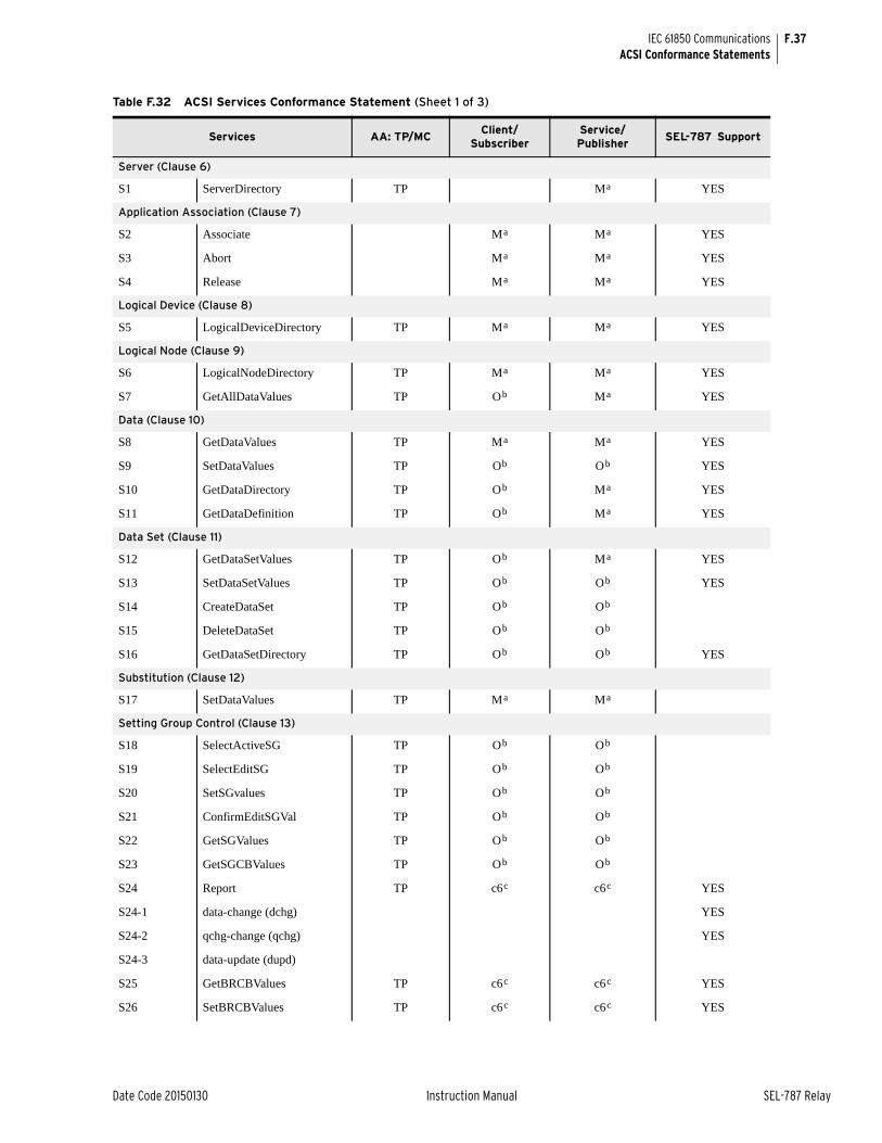
F.37
Date Code 20150130 Instruction Manual SEL-787 Relay
IEC 61850 CommunicationsACSI Conformance Statements
Table F.32 ACSI Services Conformance Statement (Sheet 1 of 3)
Services AA: TP/MCClient/
SubscriberService/Publisher
SEL-787 Support
Server (Clause 6)
S1 ServerDirectory TP Ma YES
Application Association (Clause 7)
S2 Associate Ma Ma YES
S3 Abort Ma Ma YES
S4 Release Ma Ma YES
Logical Device (Clause 8)
S5 LogicalDeviceDirectory TP Ma Ma YES
Logical Node (Clause 9)
S6 LogicalNodeDirectory TP Ma Ma YES
S7 GetAllDataValues TP Ob Ma YES
Data (Clause 10)
S8 GetDataValues TP Ma Ma YES
S9 SetDataValues TP Ob Ob YES
S10 GetDataDirectory TP Ob Ma YES
S11 GetDataDefinition TP Ob Ma YES
Data Set (Clause 11)
S12 GetDataSetValues TP Ob Ma YES
S13 SetDataSetValues TP Ob Ob YES
S14 CreateDataSet TP Ob Ob
S15 DeleteDataSet TP Ob Ob
S16 GetDataSetDirectory TP Ob Ob YES
Substitution (Clause 12)
S17 SetDataValues TP Ma Ma
Setting Group Control (Clause 13)
S18 SelectActiveSG TP Ob Ob
S19 SelectEditSG TP Ob Ob
S20 SetSGvalues TP Ob Ob
S21 ConfirmEditSGVal TP Ob Ob
S22 GetSGValues TP Ob Ob
S23 GetSGCBValues TP Ob Ob
S24 Report TP c6c c6c YES
S24-1 data-change (dchg) YES
S24-2 qchg-change (qchg) YES
S24-3 data-update (dupd)
S25 GetBRCBValues TP c6c c6c YES
S26 SetBRCBValues TP c6c c6c YES
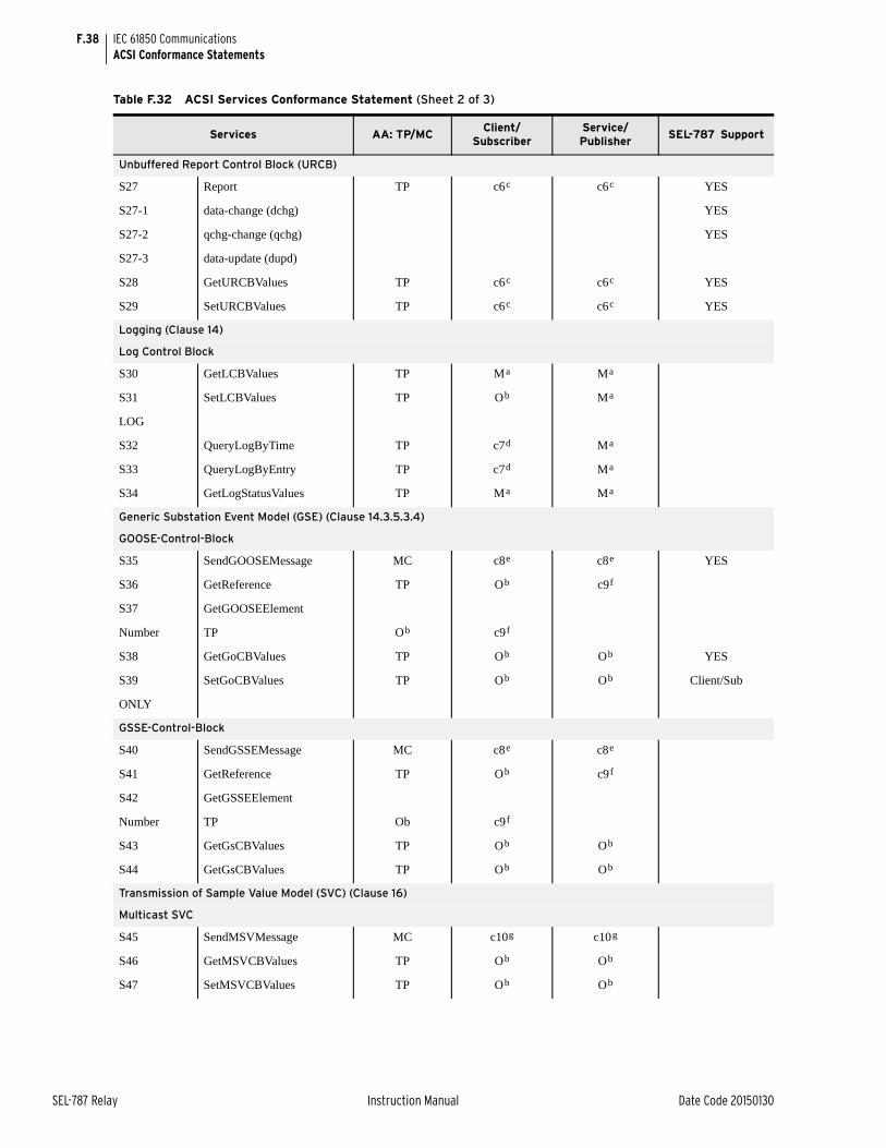
F.38
SEL-787 Relay Instruction Manual Date Code 20150130
IEC 61850 CommunicationsACSI Conformance Statements
Unbuffered Report Control Block (URCB)
S27 Report TP c6c c6c YES
S27-1 data-change (dchg) YES
S27-2 qchg-change (qchg) YES
S27-3 data-update (dupd)
S28 GetURCBValues TP c6c c6c YES
S29 SetURCBValues TP c6c c6c YES
Logging (Clause 14)
Log Control Block
S30 GetLCBValues TP Ma Ma
S31 SetLCBValues TP Ob Ma
LOG
S32 QueryLogByTime TP c7d Ma
S33 QueryLogByEntry TP c7d Ma
S34 GetLogStatusValues TP Ma Ma
Generic Substation Event Model (GSE) (Clause 14.3.5.3.4)
GOOSE-Control-Block
S35 SendGOOSEMessage MC c8e c8e YES
S36 GetReference TP Ob c9f
S37 GetGOOSEElement
Number TP Ob c9f
S38 GetGoCBValues TP Ob Ob YES
S39 SetGoCBValues TP Ob Ob Client/Sub
ONLY
GSSE-Control-Block
S40 SendGSSEMessage MC c8e c8e
S41 GetReference TP Ob c9f
S42 GetGSSEElement
Number TP Ob c9f
S43 GetGsCBValues TP Ob Ob
S44 GetGsCBValues TP Ob Ob
Transmission of Sample Value Model (SVC) (Clause 16)
Multicast SVC
S45 SendMSVMessage MC c10g c10g
S46 GetMSVCBValues TP Ob Ob
S47 SetMSVCBValues TP Ob Ob
Table F.32 ACSI Services Conformance Statement (Sheet 2 of 3)
Services AA: TP/MCClient/
SubscriberService/Publisher
SEL-787 Support
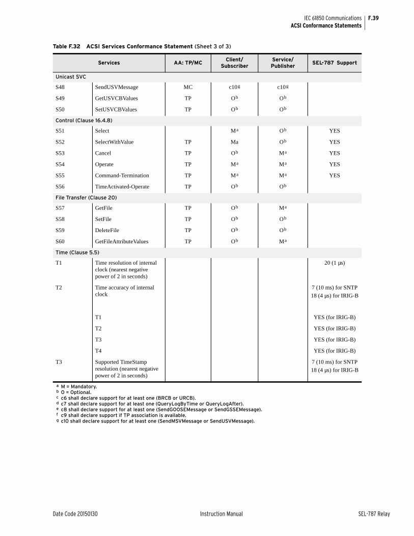
F.39
Date Code 20150130 Instruction Manual SEL-787 Relay
IEC 61850 CommunicationsACSI Conformance Statements
Unicast SVC
S48 SendUSVMessage MC c10g c10g
S49 GetUSVCBValues TP Ob Ob
S50 SetUSVCBValues TP Ob Ob
Control (Clause 16.4.8)
S51 Select Ma Ob YES
S52 SelectWithValue TP Ma Ob YES
S53 Cancel TP Ob Ma YES
S54 Operate TP Ma Ma YES
S55 Command-Termination TP Ma Ma YES
S56 TimeActivated-Operate TP Ob Ob
File Transfer (Clause 20)
S57 GetFile TP Ob Ma
S58 SetFile TP Ob Ob
S59 DeleteFile TP Ob Ob
S60 GetFileAttributeValues TP Ob Ma
Time (Clause 5.5)
T1 Time resolution of internal clock (nearest negative power of 2 in seconds)
20 (1 µs)
T2 Time accuracy of internal clock
7 (10 ms) for SNTP
18 (4 µs) for IRIG-B
T1 YES (for IRIG-B)
T2 YES (for IRIG-B)
T3 YES (for IRIG-B)
T4 YES (for IRIG-B)
T3 Supported TimeStamp resolution (nearest negative power of 2 in seconds)
7 (10 ms) for SNTP
18 (4 µs) for IRIG-B
a M = Mandatory.b O = Optional.c c6 shall declare support for at least one (BRCB or URCB).d c7 shall declare support for at least one (QueryLogByTime or QueryLogAfter).e c8 shall declare support for at least one (SendGOOSEMessage or SendGSSEMessage).f c9 shall declare support if TP association is available.g c10 shall declare support for at least one (SendMSVMessage or SendUSVMessage).
Table F.32 ACSI Services Conformance Statement (Sheet 3 of 3)
Services AA: TP/MCClient/
SubscriberService/Publisher
SEL-787 Support

This page intentionally left blank
Date Code 20150130 Instruction Manual SEL-787 Relay
Appendix GDeviceNet Communications
Instruction Manual
OverviewThis appendix describes DeviceNet communications features supported by the SEL-787 Transformer Protection Relay.
DeviceNet is a low-level communications network that provides direct connectivity among industrial devices, resulting in improved communication and device-level diagnostics that are otherwise either unavailable or inaccessible through expensive hardwired I/O interfaces. Industrial devices for which DeviceNet provides this direct connectivity include limit switches, photoelectric sensors, valve manifolds, motor starters, process sensors, bar code readers, variable frequency drives, panel displays, and operator interfaces.
The SEL DeviceNet Communications Card User’s Guide contains more information on the installation and use of the DeviceNet card or the DeviceNet protocol.
The BLOCK MODBUS SET setting is used to block relay settings changes via Modbus or DeviceNet protocols. The factory-default setting, BLKMBSET := NONE, allows all setting changes via Modbus or DeviceNet communications. The BLKMBSET := R_S setting prevents Modbus or DeviceNet communications from resetting to the factory-default settings. The BLKMBSET := ALL setting blocks all changes to the settings via the Modbus or the DeviceNet protocol.
You are strongly advised to change the BLKMBSET (BLOCK MODBUS SET) := ALL if you do not want the PLC (Programmable Logic Controller) or DCS (Distributed Control System) to send the settings to the SEL-787 relay. There is a strong possibility that under special conditions like a reboot, the PLC/DCS will send default settings to the relay, overwriting the existing settings. To protect the existing settings under these conditions it is highly recommended to set the setting to "ALL."
NOTE: Be aware of the following setting in the relay:Under Global settings category Access Control, there is a setting called BLOCK MODBUS SET.
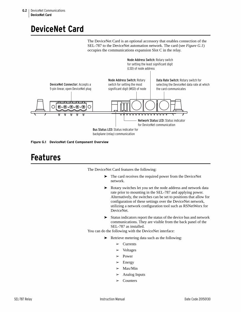
G.2
SEL-787 Relay Instruction Manual Date Code 20150130
DeviceNet CommunicationsDeviceNet Card
DeviceNet CardThe DeviceNet Card is an optional accessory that enables connection of the SEL-787 to the DeviceNet automation network. The card (see Figure G.1) occupies the communications expansion Slot C in the relay.
Figure G.1 DeviceNet Card Component Overview
FeaturesThe DeviceNet Card features the following:
➤ The card receives the required power from the DeviceNet network.
➤ Rotary switches let you set the node address and network data rate prior to mounting in the SEL-787 and applying power. Alternatively, the switches can be set to positions that allow for configuration of these settings over the DeviceNet network, utilizing a network configuration tool such as RSNetWorx for DeviceNet.
➤ Status indicators report the status of the device bus and network communications. They are visible from the back panel of the SEL-787 as installed.
You can do the following with the DeviceNet interface:
➤ Retrieve metering data such as the following:
➢ Currents
➢ Voltages
➢ Power
➢ Energy
➢ Max/Min
➢ Analog Inputs
➢ Counters
Node Address Switch: Rotary switch for setting the least significant digit (LSD) of node address
DeviceNet Connector: Accepts a 5-pin linear, open DeviceNet plug
Node Address Switch: Rotary switch for setting the most significant digit (MSD) of node
Data Rate Switch: Rotary switch for selecting the DeviceNet data rate at which the card communicates
Network Status LED: Status indicator for DeviceNet communication
Bus Status LED: Status indicator for backplane (relay) communication
G.3
Date Code 20150130 Instruction Manual SEL-787 Relay
DeviceNet CommunicationsElectronic Data Sheet
➤ Retrieve and modify relay settings
➤ Read and set time
➤ Monitor device status, trip/warning status, and I/O status
➤ Perform high-speed control
➤ Reset trip, target, and accumulated data
➤ Retrieve events history
The DeviceNet interface can be configured through the use of address and data transmission rate switches. Indicators on the card at the back of the relay show network status and network activity.
Electronic Data Sheet
The Electronic Data Sheet (EDS) is a specially formatted file that includes configurable parameters for the device and public interfaces to those parameters. The EDS file contains information such as number of parameters; groupings; parameter name; minimum, maximum, and default values; units; data format; and scaling. This information makes possible user-friendly configuration tools (e.g., RSNetWorx for DeviceNet or DeviceNet Configurator from OMRON®) for device parameter monitoring, modification, or both. The interface to the device can also be easily updated without revision of the configuration software tool itself.
All the registers defined in the Modbus® Register Map (Table E.34) are available as parameters in a DeviceNet configuration. Parameter names, data ranges, and scaling; enumeration values and strings; parameter groups; and product information are the same as specified in the Modbus Register Map defined in Table E.34. The parameter numbers are offset by a count of 100 from the register numbers.
The EDS file for the SEL-787, SEL-xxxRxxx.EDS, is located on the SEL-787 Product Literature CD. It can also be downloaded from the SEL website at www.selinc.com.
Complete specifications for the DeviceNet protocol are available on the Open DeviceNet Vendor’s Association (ODVA) website www.odva.org. ODVA is an independent supplier organization that manages the DeviceNet specification and supports the worldwide growth of DeviceNet.

This page intentionally left blank

Date Code 20150130 Instruction Manual SEL-787 Relay
Appendix HSynchrophasors
Instruction Manual
IntroductionThe SEL-787 Transformer Protection Relay provides Phasor Measurement Control Unit (PMCU) capabilities when connected to an IRIG-B time source with an accuracy of ±10 µs or better. Synchrophasor data are available via the MET PM ASCII command and the C37.118 Protocol.
Synchrophasor measurement refers to the concept of providing measurements taken on a synchronized schedule at precise instants in time. A high-accuracy clock, commonly called a Global Positioning System (GPS) receiver such as the SEL-2407 Satellite-Synchronized Clock, makes synchrophasor measurement possible.
The availability of an accurate time reference over a large geographic area allows multiple devices, such as SEL-787 relays, to synchronize the gathering of power system data. The accurate clock allows precise event report triggering and other off-line analysis functions.
The SEL-787 Global settings class contains the synchrophasor settings, including the choice of transmitted synchrophasor data set. The Port settings class selects which serial port(s) can be used for synchrophasor protocol use. See Settings for Synchrophasors on page H.4.
The SEL-787 timekeeping function generates status Relay Word bits and time-quality information that is important for synchrophasor measurement. Some protection SELOGIC® control equation variables, and programmable digital trigger information is also added to the Relay Word bits for synchrophasors.See Synchrophasor Relay Word Bits on page H.9.
When synchrophasor measurement is enabled, the SEL-787 creates the synchrophasor data set at a user-defined rate. Synchrophasor data are available in ASCII format over a serial port set to PROTO = SEL. See View Synchrophasors Using the MET PM Command on page H.10.
The value of synchrophasor data increases greatly when the data can be shared over a communications network in real time. A synchrophasor protocol is available in the SEL-787 that allows for a centralized device to collect data efficiently from several phasor measurement units (PMUs). Some possible uses of a system-wide synchrophasor system include the following:
➤ Power-system state measurement
➤ Wide-area network protection and control schemes
➤ Small-signal analysis
➤ Power-system disturbance analysis
The SEL-3306 Synchrophasor Processor is a PC-based communications processor specifically designed to interface with PMUs. The SEL-3306 has
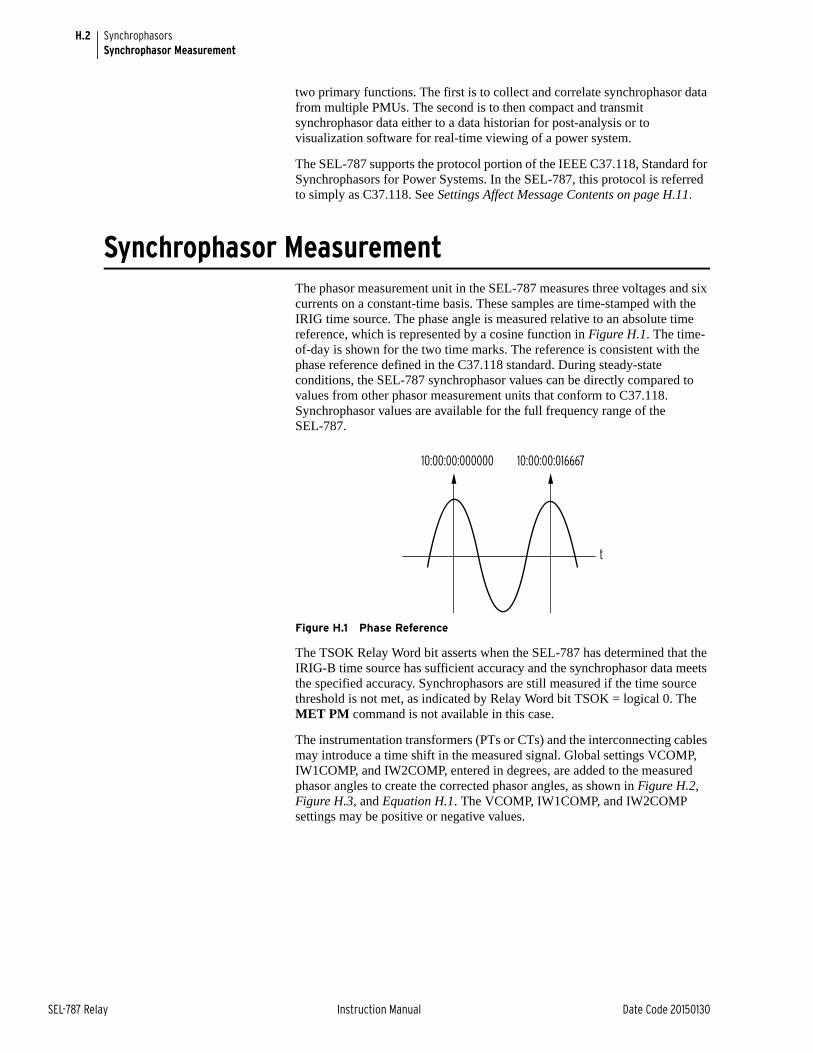
H.2
SEL-787 Relay Instruction Manual Date Code 20150130
SynchrophasorsSynchrophasor Measurement
two primary functions. The first is to collect and correlate synchrophasor data from multiple PMUs. The second is to then compact and transmit synchrophasor data either to a data historian for post-analysis or to visualization software for real-time viewing of a power system.
The SEL-787 supports the protocol portion of the IEEE C37.118, Standard for Synchrophasors for Power Systems. In the SEL-787, this protocol is referred to simply as C37.118. See Settings Affect Message Contents on page H.11.
Synchrophasor MeasurementThe phasor measurement unit in the SEL-787 measures three voltages and six currents on a constant-time basis. These samples are time-stamped with the IRIG time source. The phase angle is measured relative to an absolute time reference, which is represented by a cosine function in Figure H.1. The time-of-day is shown for the two time marks. The reference is consistent with the phase reference defined in the C37.118 standard. During steady-state conditions, the SEL-787 synchrophasor values can be directly compared to values from other phasor measurement units that conform to C37.118. Synchrophasor values are available for the full frequency range of the SEL-787.
Figure H.1 Phase Reference
The TSOK Relay Word bit asserts when the SEL-787 has determined that the IRIG-B time source has sufficient accuracy and the synchrophasor data meets the specified accuracy. Synchrophasors are still measured if the time source threshold is not met, as indicated by Relay Word bit TSOK = logical 0. The MET PM command is not available in this case.
The instrumentation transformers (PTs or CTs) and the interconnecting cables may introduce a time shift in the measured signal. Global settings VCOMP, IW1COMP, and IW2COMP, entered in degrees, are added to the measured phasor angles to create the corrected phasor angles, as shown in Figure H.2, Figure H.3, and Equation H.1. The VCOMP, IW1COMP, and IW2COMP settings may be positive or negative values.
t
10:00:00:000000 10:00:00:016667
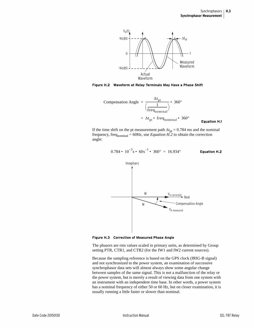
H.3
Date Code 20150130 Instruction Manual SEL-787 Relay
SynchrophasorsSynchrophasor Measurement
Figure H.2 Waveform at Relay Terminals May Have a Phase Shift
Equation H.1
If the time shift on the pt measurement path tpt = 0.784 ms and the nominal frequency, freqnominal = 60Hz, use Equation H.2 to obtain the correction angle:
Equation H.2
Figure H.3 Correction of Measured Phase Angle
The phasors are rms values scaled in primary units, as determined by Group setting PTR, CTR1, and CTR2 (for the IW1 and IW2 current sources).
Because the sampling reference is based on the GPS clock (IRIG-B signal) and not synchronized to the power system, an examination of successive synchrophasor data sets will almost always show some angular change between samples of the same signal. This is not a malfunction of the relay or the power system, but is merely a result of viewing data from one system with an instrument with an independent time base. In other words, a power system has a nominal frequency of either 50 or 60 Hz, but on closer examination, it is usually running a little faster or slower than nominal.
94.851
–94.851
Δtpt
0 t
VA(t)
Actual Waveform
Measured Waveform
Compensation Angletpt
1freqnominal---------------------------- ---------------------------------- 360• =
tpt freqnominal 360• • =
0.784 103–s 60s
1–360• • • 16.934=
Imaginary
RealM
MVA measured
VA corrected
Compensation Angle
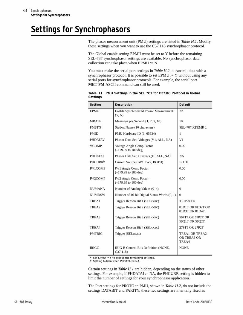
H.4
SEL-787 Relay Instruction Manual Date Code 20150130
SynchrophasorsSettings for Synchrophasors
Settings for SynchrophasorsThe phasor measurement unit (PMU) settings are listed in Table H.1. Modify these settings when you want to use the C37.118 synchrophasor protocol.
The Global enable setting EPMU must be set to Y before the remaining SEL-787 synchrophasor settings are available. No synchrophasor data collection can take place when EPMU := N.
You must make the serial port settings in Table H.2 to transmit data with a synchrophasor protocol. It is possible to set EPMU := Y without using any serial ports for synchrophasor protocols. For example, the serial port MET PM ASCII command can still be used.
Certain settings in Table H.1 are hidden, depending on the status of other settings. For example, if PHDATAI := NA, the PHCURR setting is hidden to limit the number of settings for your synchrophasor application.
The Port settings for PROTO := PMU, shown in Table H.2, do not include the settings DATABIT and PARITY; these two settings are internally fixed as
Table H.1 PMU Settings in the SEL-787 for C37.118 Protocol in Global Settings
Setting Description Default
EPMU Enable Synchronized Phasor Measurement (Y, N)
Na
a Set EPMU := Y to access the remaining settings.
MRATE Messages per Second {1, 2, 5, 10} 10
PMSTN Station Name (16 characters) SEL-787 XFRMR 1
PMID PMU Hardware ID (1–65534) 1
PHDATAV Phasor Data Set, Voltages (V1, ALL, NA) V1
VCOMP Voltage Angle Comp Factor (–179.99 to 180 deg)
0.00
PHDATAI Phasor Data Set, Currents (I1, ALL, NA) NA
PHCURRb
b Setting hidden when PHDATAI := NA.
Current Source (IW1, IW2, BOTH) BOTH
IW1COMP IW1 Angle Comp Factor (–179.99 to 180 deg)
0.00
IW2COMP IW2 Angle Comp Factor (–179.99 to 180 deg)
0.00
NUMANA Number of Analog Values (0–4) 0
NUMDSW Number of 16-bit Digital Status Words (0, 1) 0
TREA1 Trigger Reason Bit 1 (SELOGIC) TRIP or ER
TREA2 Trigger Reason Bit 2 (SELOGIC) 81D1T OR 81D2T OR 81D3T OR 81D4T
TREA3 Trigger Reason Bit 3 (SELOGIC) 59P1T OR 59P2T OR 59Q1T OR 59Q2T
TREA4 Trigger Reason Bit 4 (SELOGIC) 27P1T OR 27P2T
PMTRIG Trigger (SELOGIC) TREA1 OR TREA2 OR TREA3 OR TREA4
IRIGC IRIG-B Control Bits Definition (NONE, C37.118)
NONE
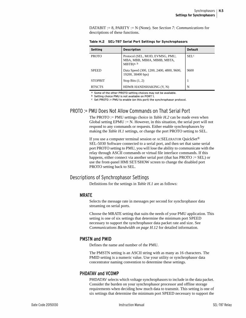
H.5
Date Code 20150130 Instruction Manual SEL-787 Relay
SynchrophasorsSettings for Synchrophasors
DATABIT := 8, PARITY := N (None). See Section 7: Communications for descriptions of these functions.
PROTO := PMU Does Not Allow Commands on That Serial PortThe PROTO := PMU settings choice in Table H.2 can be made even when Global setting EPMU := N. However, in this situation, the serial port will not respond to any commands or requests. Either enable synchrophasors by making the Table H.1 settings, or change the port PROTO setting to SEL.
If you use a computer terminal session or ACSELERATOR QuickSet® SEL-5030 Software connected to a serial port, and then set that same serial port PROTO setting to PMU, you will lose the ability to communicate with the relay through ASCII commands or virtual file interface commands. If this happens, either connect via another serial port (that has PROTO := SEL) or use the front-panel HMI SET/SHOW screen to change the disabled port PROTO setting back to SEL.
Descriptions of Synchrophasor SettingsDefinitions for the settings in Table H.1 are as follows:
MRATESelects the message rate in messages per second for synchrophasor data streaming on serial ports.
Choose the MRATE setting that suits the needs of your PMU application. This setting is one of six settings that determine the minimum port SPEED necessary to support the synchrophasor data packet rate and size. See Communications Bandwidth on page H.12 for detailed information.
PMSTN and PMIDDefines the name and number of the PMU.
The PMSTN setting is an ASCII string with as many as 16 characters. The PMID setting is a numeric value. Use your utility or synchrophasor data concentrator naming convention to determine these settings.
PHDATAV and VCOMPPHDATAV selects which voltage synchrophasors to include in the data packet. Consider the burden on your synchrophasor processor and offline storage requirements when deciding how much data to transmit. This setting is one of six settings that determine the minimum port SPEED necessary to support the
Table H.2 SEL-787 Serial Port Settings for Synchrophasors
Setting Description Default
PROTO Protocol (SEL, MOD, EVMSG, PMU, MBA, MBB, MB8A, MB8B, MBTA, MBTB)a, b
a Some of the other PROTO setting choices may not be available.b Setting choice PMU is not available on PORT 1.
SELc
c Set PROTO := PMU to enable (on this port) the synchrophasor protocol.
SPEED Data Speed (300, 1200, 2400, 4800, 9600, 19200, 38400 bps)
9600
STOPBIT Stop Bits (1, 2) 1
RTSCTS HDWR HANDSHAKING (Y, N) N
H.6
SEL-787 Relay Instruction Manual Date Code 20150130
SynchrophasorsSettings for Synchrophasors
synchrophasor data packet rate and size—see Communications Bandwidth on page H.12 for detailed information.
➤ PHDATAV := V1 will transmit only positive-sequence voltage, V1
➤ PHDATAV := ALL will transmit V1, VA, VB, and VC
➤ PHDATAV := NA will not transmit any voltages
Table H.3 describes the order of synchrophasors inside the data packet.
The VCOMP setting allows correction for any steady-state voltage phase errors (from the potential transformers or wiring characteristics). See Synchrophasor Measurement on page H.2 for details on this setting.
PHDATAI, PHCURR, IW1COMP, and IW2COMPPHDATAI and PHCURR select which current synchrophasors to include in the data packet. Consider the burden on your synchrophasor processor and offline storage requirements when deciding how much data to transmit. These settings are two of the six settings that determine the minimum port SPEED necessary to support the synchrophasor data packet rate and size—see Communications Bandwidth on page H.12 for detailed information.
➤ PHDATAI := I1 will transmit only positive-sequence current, I1
➤ PHDATAI := ALL will transmit I1, IA, IB, and IC for the Windings selected by PHCURR
➤ PHDATAI := NA will not transmit any currents
PHCURR selects the source current(s) for the synchrophasor data selected by PHDATAI.
➤ PHCURR := IW1 uses the currents measured on the IAW1, IBW1, and ICW1 inputs
➤ PHCURR := IW2 uses the currents measured on the IAW2, IBW2, and ICW2 inputs
➤ PHCURR:= BOTH uses the currents measured on both the I_W1 inputs and I_W2 inputs
Table H.3 describes the order of synchrophasors inside the data packet.
The IW1COMP and IW2COMP settings allow correction for any steady-state phase errors (from the current transformers or wiring characteristics). See Synchrophasor Measurement on page H.2 for details on these settings.
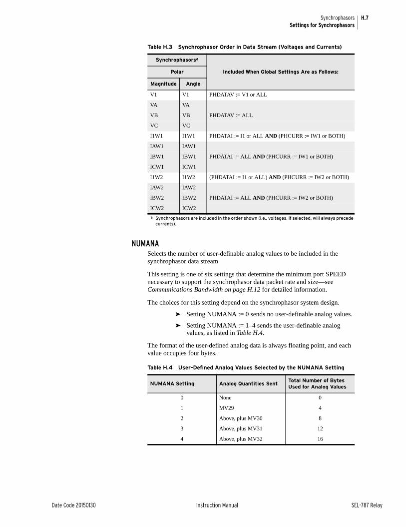
H.7
Date Code 20150130 Instruction Manual SEL-787 Relay
SynchrophasorsSettings for Synchrophasors
NUMANASelects the number of user-definable analog values to be included in the synchrophasor data stream.
This setting is one of six settings that determine the minimum port SPEED necessary to support the synchrophasor data packet rate and size—see Communications Bandwidth on page H.12 for detailed information.
The choices for this setting depend on the synchrophasor system design.
➤ Setting NUMANA := 0 sends no user-definable analog values.
➤ Setting NUMANA := 1–4 sends the user-definable analog values, as listed in Table H.4.
The format of the user-defined analog data is always floating point, and each value occupies four bytes.
Table H.3 Synchrophasor Order in Data Stream (Voltages and Currents)
Synchrophasorsa
a Synchrophasors are included in the order shown (i.e., voltages, if selected, will always precede currents).
Included When Global Settings Are as Follows:Polar
Magnitude Angle
V1 V1 PHDATAV := V1 or ALL
VA VA
VB VB PHDATAV := ALL
VC VC
I1W1 I1W1 PHDATAI := I1 or ALL AND (PHCURR := IW1 or BOTH)
IAW1 IAW1
IBW1 IBW1 PHDATAI := ALL AND (PHCURR := IW1 or BOTH)
ICW1 ICW1
I1W2 I1W2 (PHDATAI := I1 or ALL) AND (PHCURR := IW2 or BOTH)
IAW2 IAW2
IBW2 IBW2 PHDATAI := ALL AND (PHCURR := IW2 or BOTH)
ICW2 ICW2
Table H.4 User-Defined Analog Values Selected by the NUMANA Setting
NUMANA Setting Analog Quantities SentTotal Number of Bytes Used for Analog Values
0 None 0
1 MV29 4
2 Above, plus MV30 8
3 Above, plus MV31 12
4 Above, plus MV32 16
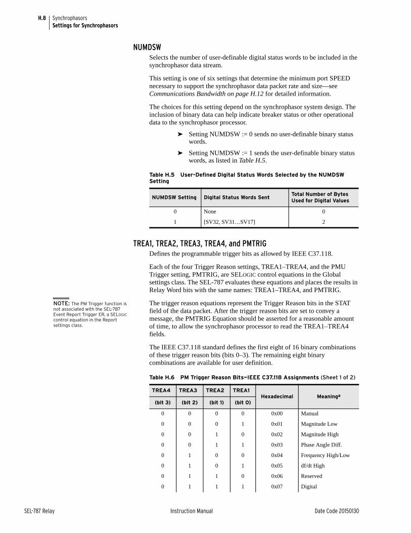
H.8
SEL-787 Relay Instruction Manual Date Code 20150130
SynchrophasorsSettings for Synchrophasors
NUMDSWSelects the number of user-definable digital status words to be included in the synchrophasor data stream.
This setting is one of six settings that determine the minimum port SPEED necessary to support the synchrophasor data packet rate and size—see Communications Bandwidth on page H.12 for detailed information.
The choices for this setting depend on the synchrophasor system design. The inclusion of binary data can help indicate breaker status or other operational data to the synchrophasor processor.
➤ Setting NUMDSW := 0 sends no user-definable binary status words.
➤ Setting NUMDSW := 1 sends the user-definable binary status words, as listed in Table H.5.
TREA1, TREA2, TREA3, TREA4, and PMTRIGDefines the programmable trigger bits as allowed by IEEE C37.118.
Each of the four Trigger Reason settings, TREA1–TREA4, and the PMU Trigger setting, PMTRIG, are SELOGIC control equations in the Global settings class. The SEL-787 evaluates these equations and places the results in Relay Word bits with the same names: TREA1–TREA4, and PMTRIG.
The trigger reason equations represent the Trigger Reason bits in the STAT field of the data packet. After the trigger reason bits are set to convey a message, the PMTRIG Equation should be asserted for a reasonable amount of time, to allow the synchrophasor processor to read the TREA1–TREA4 fields.
The IEEE C37.118 standard defines the first eight of 16 binary combinations of these trigger reason bits (bits 0–3). The remaining eight binary combinations are available for user definition.
Table H.5 User-Defined Digital Status Words Selected by the NUMDSW Setting
NUMDSW Setting Digital Status Words Sent Total Number of Bytes Used for Digital Values
0 None 0
1 [SV32, SV31…SV17] 2
Table H.6 PM Trigger Reason Bits—IEEE C37.118 Assignments (Sheet 1 of 2)
TREA4 TREA3 TREA2 TREA1Hexadecimal Meaninga
(bit 3) (bit 2) (bit 1) (bit 0)
0 0 0 0 0x00 Manual
0 0 0 1 0x01 Magnitude Low
0 0 1 0 0x02 Magnitude High
0 0 1 1 0x03 Phase Angle Diff.
0 1 0 0 0x04 Frequency High/Low
0 1 0 1 0x05 df/dt High
0 1 1 0 0x06 Reserved
0 1 1 1 0x07 Digital
NOTE: The PM Trigger function is not associated with the SEL-787 Event Report Trigger ER, a SELOGIC control equation in the Report settings class.
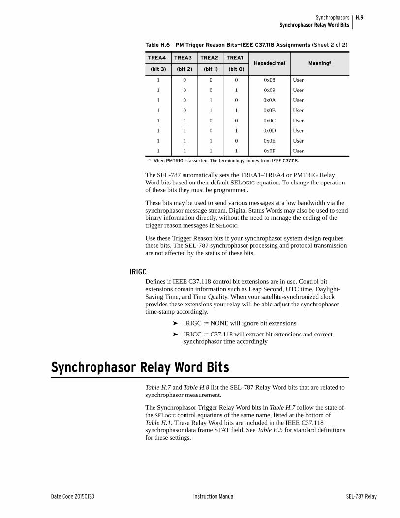
H.9
Date Code 20150130 Instruction Manual SEL-787 Relay
SynchrophasorsSynchrophasor Relay Word Bits
The SEL-787 automatically sets the TREA1–TREA4 or PMTRIG Relay Word bits based on their default SELOGIC equation. To change the operation of these bits they must be programmed.
These bits may be used to send various messages at a low bandwidth via the synchrophasor message stream. Digital Status Words may also be used to send binary information directly, without the need to manage the coding of the trigger reason messages in SELOGIC.
Use these Trigger Reason bits if your synchrophasor system design requires these bits. The SEL-787 synchrophasor processing and protocol transmission are not affected by the status of these bits.
IRIGCDefines if IEEE C37.118 control bit extensions are in use. Control bit extensions contain information such as Leap Second, UTC time, Daylight-Saving Time, and Time Quality. When your satellite-synchronized clock provides these extensions your relay will be able adjust the synchrophasor time-stamp accordingly.
➤ IRIGC := NONE will ignore bit extensions
➤ IRIGC := C37.118 will extract bit extensions and correct synchrophasor time accordingly
Synchrophasor Relay Word BitsTable H.7 and Table H.8 list the SEL-787 Relay Word bits that are related to synchrophasor measurement.
The Synchrophasor Trigger Relay Word bits in Table H.7 follow the state of the SELOGIC control equations of the same name, listed at the bottom of Table H.1. These Relay Word bits are included in the IEEE C37.118 synchrophasor data frame STAT field. See Table H.5 for standard definitions for these settings.
1 0 0 0 0x08 User
1 0 0 1 0x09 User
1 0 1 0 0x0A User
1 0 1 1 0x0B User
1 1 0 0 0x0C User
1 1 0 1 0x0D User
1 1 1 0 0x0E User
1 1 1 1 0x0F User
a When PMTRIG is asserted. The terminology comes from IEEE C37.118.
Table H.6 PM Trigger Reason Bits—IEEE C37.118 Assignments (Sheet 2 of 2)
TREA4 TREA3 TREA2 TREA1Hexadecimal Meaninga
(bit 3) (bit 2) (bit 1) (bit 0)
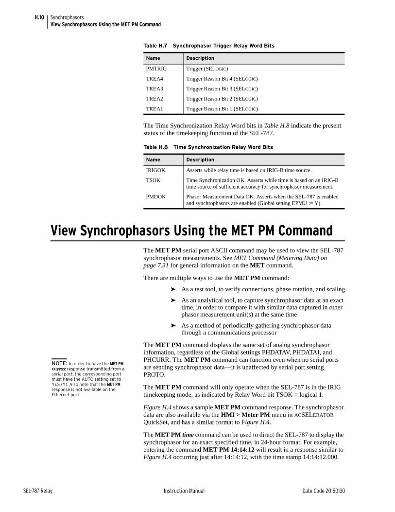
H.10
SEL-787 Relay Instruction Manual Date Code 20150130
SynchrophasorsView Synchrophasors Using the MET PM Command
The Time Synchronization Relay Word bits in Table H.8 indicate the present status of the timekeeping function of the SEL-787.
View Synchrophasors Using the MET PM CommandThe MET PM serial port ASCII command may be used to view the SEL-787 synchrophasor measurements. See MET Command (Metering Data) on page 7.31 for general information on the MET command.
There are multiple ways to use the MET PM command:
➤ As a test tool, to verify connections, phase rotation, and scaling
➤ As an analytical tool, to capture synchrophasor data at an exact time, in order to compare it with similar data captured in other phasor measurement unit(s) at the same time
➤ As a method of periodically gathering synchrophasor data through a communications processor
The MET PM command displays the same set of analog synchrophasor information, regardless of the Global settings PHDATAV, PHDATAI, and PHCURR. The MET PM command can function even when no serial ports are sending synchrophasor data—it is unaffected by serial port setting PROTO.
The MET PM command will only operate when the SEL-787 is in the IRIG timekeeping mode, as indicated by Relay Word bit TSOK = logical 1.
Figure H.4 shows a sample MET PM command response. The synchrophasor data are also available via the HMI > Meter PM menu in ACSELERATOR QuickSet, and has a similar format to Figure H.4.
The MET PM time command can be used to direct the SEL-787 to display the synchrophasor for an exact specified time, in 24-hour format. For example, entering the command MET PM 14:14:12 will result in a response similar to Figure H.4 occurring just after 14:14:12, with the time stamp 14:14:12.000.
Table H.7 Synchrophasor Trigger Relay Word Bits
Name Description
PMTRIG Trigger (SELOGIC)
TREA4 Trigger Reason Bit 4 (SELOGIC)
TREA3 Trigger Reason Bit 3 (SELOGIC)
TREA2 Trigger Reason Bit 2 (SELOGIC)
TREA1 Trigger Reason Bit 1 (SELOGIC)
Table H.8 Time Synchronization Relay Word Bits
Name Description
IRIGOK Asserts while relay time is based on IRIG-B time source.
TSOK Time Synchronization OK. Asserts while time is based on an IRIG-B time source of sufficient accuracy for synchrophasor measurement.
PMDOK Phasor Measurement Data OK. Asserts when the SEL-787 is enabled and synchrophasors are enabled (Global setting EPMU := Y).
NOTE: In order to have the MET PM xx:yy:zz response transmitted from a serial port, the corresponding port must have the AUTO setting set to YES (Y). Also note that the MET PM response is not available on the Ethernet port.
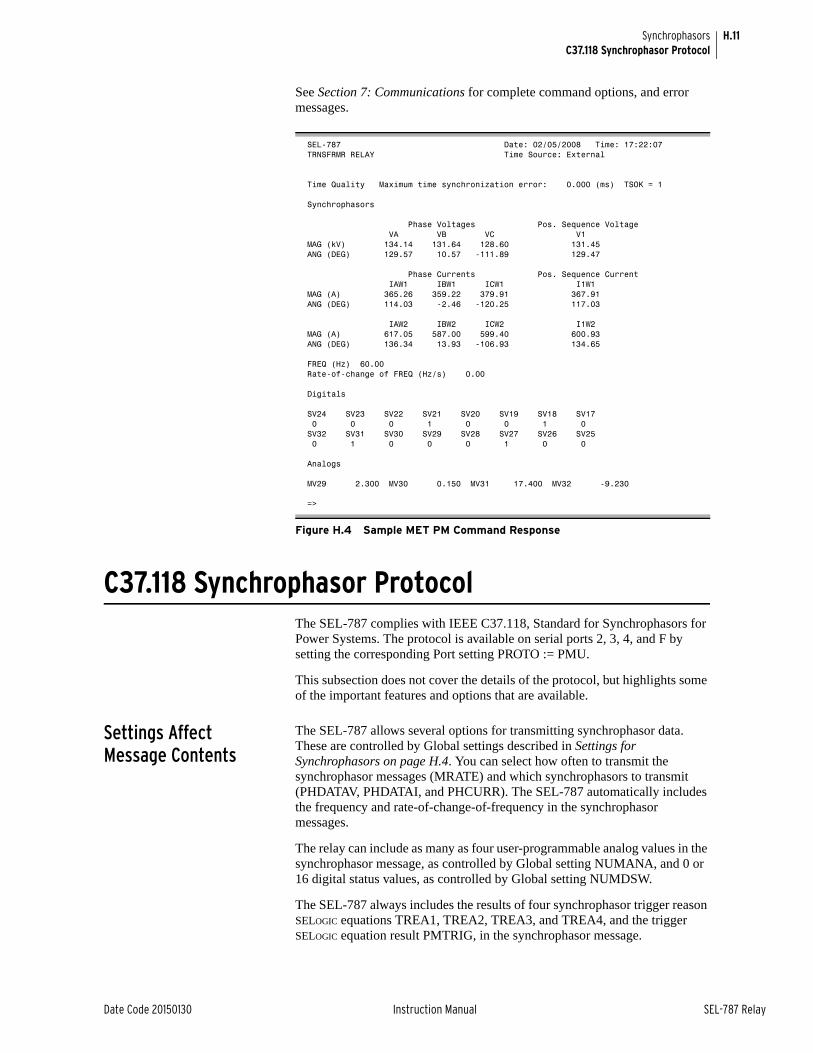
H.11
Date Code 20150130 Instruction Manual SEL-787 Relay
SynchrophasorsC37.118 Synchrophasor Protocol
See Section 7: Communications for complete command options, and error messages.
C37.118 Synchrophasor ProtocolThe SEL-787 complies with IEEE C37.118, Standard for Synchrophasors for Power Systems. The protocol is available on serial ports 2, 3, 4, and F by setting the corresponding Port setting PROTO := PMU.
This subsection does not cover the details of the protocol, but highlights some of the important features and options that are available.
Settings Affect Message Contents
The SEL-787 allows several options for transmitting synchrophasor data. These are controlled by Global settings described in Settings for Synchrophasors on page H.4. You can select how often to transmit the synchrophasor messages (MRATE) and which synchrophasors to transmit (PHDATAV, PHDATAI, and PHCURR). The SEL-787 automatically includes the frequency and rate-of-change-of-frequency in the synchrophasor messages.
The relay can include as many as four user-programmable analog values in the synchrophasor message, as controlled by Global setting NUMANA, and 0 or 16 digital status values, as controlled by Global setting NUMDSW.
The SEL-787 always includes the results of four synchrophasor trigger reason SELOGIC equations TREA1, TREA2, TREA3, and TREA4, and the trigger SELOGIC equation result PMTRIG, in the synchrophasor message.
SEL-787 Date: 02/05/2008 Time: 17:22:07TRNSFRMR RELAY Time Source: External
Time Quality Maximum time synchronization error: 0.000 (ms) TSOK = 1
Synchrophasors
Phase Voltages Pos. Sequence Voltage VA VB VC V1MAG (kV) 134.14 131.64 128.60 131.45ANG (DEG) 129.57 10.57 -111.89 129.47
Phase Currents Pos. Sequence Current IAW1 IBW1 ICW1 I1W1MAG (A) 365.26 359.22 379.91 367.91ANG (DEG) 114.03 -2.46 -120.25 117.03
IAW2 IBW2 ICW2 I1W2MAG (A) 617.05 587.00 599.40 600.93ANG (DEG) 136.34 13.93 -106.93 134.65
FREQ (Hz) 60.00Rate-of-change of FREQ (Hz/s) 0.00
Digitals
SV24 SV23 SV22 SV21 SV20 SV19 SV18 SV17 0 0 0 1 0 0 1 0SV32 SV31 SV30 SV29 SV28 SV27 SV26 SV25 0 1 0 0 0 1 0 0
Analogs
MV29 2.300 MV30 0.150 MV31 17.400 MV32 -9.230
=>
Figure H.4 Sample MET PM Command Response
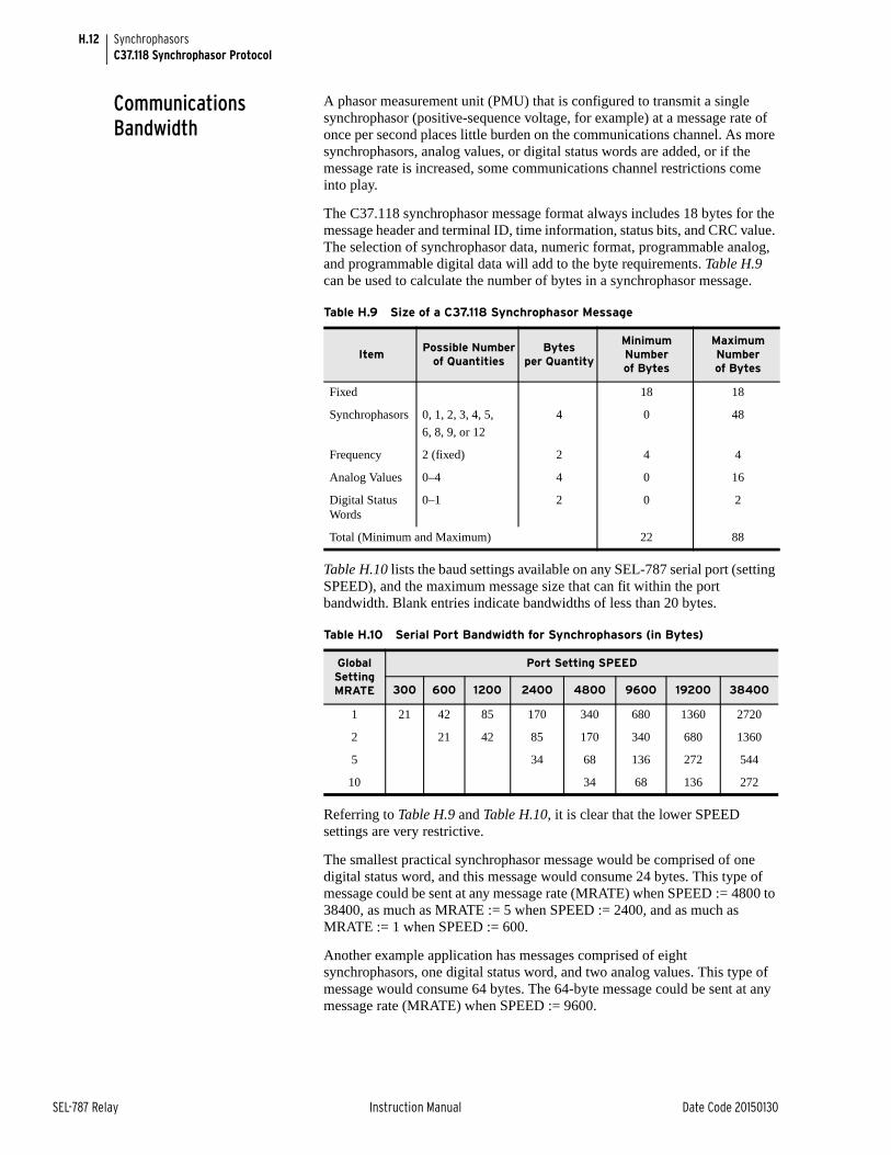
H.12
SEL-787 Relay Instruction Manual Date Code 20150130
SynchrophasorsC37.118 Synchrophasor Protocol
Communications Bandwidth
A phasor measurement unit (PMU) that is configured to transmit a single synchrophasor (positive-sequence voltage, for example) at a message rate of once per second places little burden on the communications channel. As more synchrophasors, analog values, or digital status words are added, or if the message rate is increased, some communications channel restrictions come into play.
The C37.118 synchrophasor message format always includes 18 bytes for the message header and terminal ID, time information, status bits, and CRC value. The selection of synchrophasor data, numeric format, programmable analog, and programmable digital data will add to the byte requirements. Table H.9 can be used to calculate the number of bytes in a synchrophasor message.
Table H.10 lists the baud settings available on any SEL-787 serial port (setting SPEED), and the maximum message size that can fit within the port bandwidth. Blank entries indicate bandwidths of less than 20 bytes.
Referring to Table H.9 and Table H.10, it is clear that the lower SPEED settings are very restrictive.
The smallest practical synchrophasor message would be comprised of one digital status word, and this message would consume 24 bytes. This type of message could be sent at any message rate (MRATE) when SPEED := 4800 to 38400, as much as MRATE := 5 when SPEED := 2400, and as much as MRATE := 1 when SPEED := 600.
Another example application has messages comprised of eight synchrophasors, one digital status word, and two analog values. This type of message would consume 64 bytes. The 64-byte message could be sent at any message rate (MRATE) when SPEED := 9600.
Table H.9 Size of a C37.118 Synchrophasor Message
ItemPossible Number
of Quantities Bytes
per Quantity
Minimum Numberof Bytes
Maximum Numberof Bytes
Fixed 18 18
Synchrophasors 0, 1, 2, 3, 4, 5,
6, 8, 9, or 12
4 0 48
Frequency 2 (fixed) 2 4 4
Analog Values 0–4 4 0 16
Digital Status Words
0–1 2 0 2
Total (Minimum and Maximum) 22 88
Table H.10 Serial Port Bandwidth for Synchrophasors (in Bytes)
Global Setting MRATE
Port Setting SPEED
300 600 1200 2400 4800 9600 19200 38400
1 21 42 85 170 340 680 1360 2720
2 21 42 85 170 340 680 1360
5 34 68 136 272 544
10 34 68 136 272
H.13
Date Code 20150130 Instruction Manual SEL-787 Relay
SynchrophasorsC37.118 Synchrophasor Protocol
Protocol Operation The SEL-787 will only transmit synchrophasor messages over serial ports that have setting PROTO := PMU. The connected device will typically be a synchrophasor processor, such as the SEL-3306. The synchrophasor processor controls the PMU functions of the SEL-787, with IEEE C37.118 commands, including commands to start and stop synchrophasor data transmission, and commands to request a configuration block from the relay, so the synchrophasor processor can automatically build a database structure.
Transmit Mode Control
The SEL-787 will not begin transmitting synchrophasors until an enable message is received from the synchrophasor processor. The relay will stop synchrophasor transmission when the appropriate command is received from the synchrophasor processor. The SEL-787 can also indicate when a configuration change occurs, so the synchrophasor processor can request a new configuration block and keep its database up-to-date.
The SEL-787 will only respond to configuration block request messages when it is in the non-transmitting mode.
NOTE: Only one serial port can be set to PROTO:=PMU at one time.

This page intentionally left blank
Date Code 20150130 Instruction Manual SEL-787 Relay
Appendix IMIRRORED BITS Communications
Instruction Manual
Overview
MIRRORED BITS® communications is a direct relay-to-relay communications protocol that allows IEDs to exchange information quickly, securely, and with minimal expense. Use MIRRORED BITS for functions such as remote control and remote sensing. The SEL-787 Transformer Protection Relay supports two MIRRORED BITS communications channels, designated A and B. Use the port setting PROTO to assign one of the MIRRORED BITS communications channels to a serial port; PROTO:=MBA for MIRRORED BITS communications Channel A or PROTO:=MBB for MIRRORED BITS communications Channel B. MIRRORED BITS are either Transmit MIRRORED BITS (TMB) or Received MIRRORED BITS (RMB). Transmit MIRRORED BITS include TMB1A–TMB8A (channel A) and TMB1B–TMB8B (channel B). The last letter (A or B) designates with which channel the bits are associated. Received bits include RMB1A–RMB8A and RMB1B–RMB8B. Control the transmit MIRRORED BITS in SELOGIC® control equations. Use the received MIRRORED BITS as arguments in SELOGIC control equations. The channel status bits are ROKA, RBADA, CBADA, LBOKA, ROKB, RBADB, CBADB, and LBOKB. You can also use these channel status bits as arguments in SELOGIC control equations. Use the COM command (see Section 7: Communications) for additional channel status information.
Because of different applications, the SEL product range supports several variations of the MIRRORED BITS communications protocol. Through port settings, you can set the SEL-787 for compatible operation with SEL-300 series devices, SEL-2505 Remote I/O Modules, and SEL-2100 Logic Processors. When communicating with an SEL-400 series relay, be sure to set the transmission mode setting in the SEL-400 series relay to paced transmission (TXMODE: = P).
OperationMessage Transmission
In the SEL-787, the MIRRORED BITS transmission rate is a function of both the baud rate and the power system cycle. At baud rates below 9600, the SEL-787 transmits MIRRORED BITS as fast as possible for the given baud. At rates at and above 9600 baud the SEL-787 self-paces, using a technique similar to the SEL-400 series pacing mode. There are no settings to enable or disable the self-pacing mode; the SEL-787 automatically enters the self-pacing mode at baud rates of 9600, 19200, and 38400. Table I.1 shows the transmission rates of the MIRRORED BITS messages at different baud.
IMPORTANT: Be sure to configure the port before connecting to a MIRRORED BITS device. If you connect an unconfigured port to a MIRRORED BITS device, the device will appear to be locked up.
NOTE: Complete all of the port settings for a port that you use for MIRRORED BITS communications before you connect an external MIRRORED BITS communications device. If you connect a MIRRORED BITS communications device to a port that is not set for MIRRORED BITS communications operation, the port will be continuously busy.
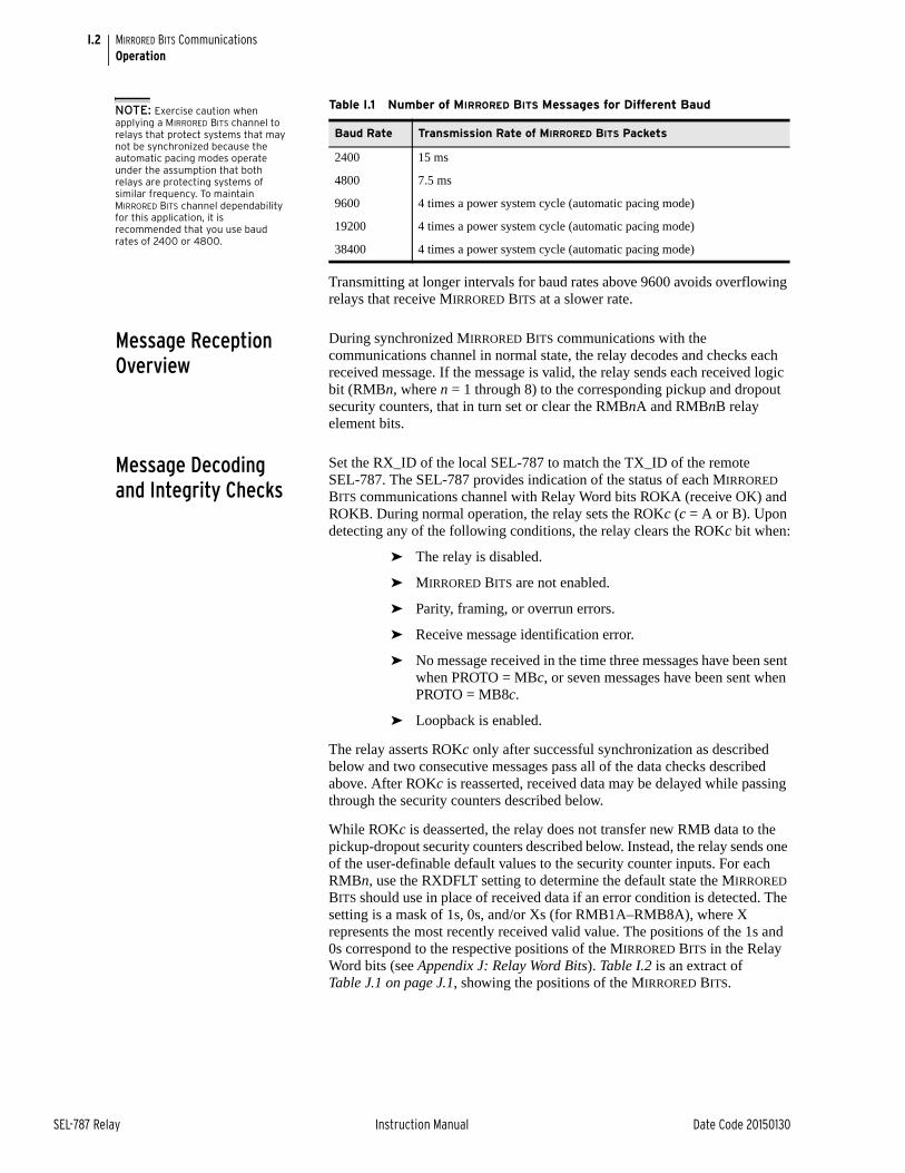
I.2
SEL-787 Relay Instruction Manual Date Code 20150130
MIRRORED BITS CommunicationsOperation
Transmitting at longer intervals for baud rates above 9600 avoids overflowing relays that receive MIRRORED BITS at a slower rate.
Message Reception Overview
During synchronized MIRRORED BITS communications with the communications channel in normal state, the relay decodes and checks each received message. If the message is valid, the relay sends each received logic bit (RMBn, where n = 1 through 8) to the corresponding pickup and dropout security counters, that in turn set or clear the RMBnA and RMBnB relay element bits.
Message Decoding and Integrity Checks
Set the RX_ID of the local SEL-787 to match the TX_ID of the remote SEL-787. The SEL-787 provides indication of the status of each MIRRORED BITS communications channel with Relay Word bits ROKA (receive OK) and ROKB. During normal operation, the relay sets the ROKc (c = A or B). Upon detecting any of the following conditions, the relay clears the ROKc bit when:
➤ The relay is disabled.
➤ MIRRORED BITS are not enabled.
➤ Parity, framing, or overrun errors.
➤ Receive message identification error.
➤ No message received in the time three messages have been sent when PROTO = MBc, or seven messages have been sent when PROTO = MB8c.
➤ Loopback is enabled.
The relay asserts ROKc only after successful synchronization as described below and two consecutive messages pass all of the data checks described above. After ROKc is reasserted, received data may be delayed while passing through the security counters described below.
While ROKc is deasserted, the relay does not transfer new RMB data to the pickup-dropout security counters described below. Instead, the relay sends one of the user-definable default values to the security counter inputs. For each RMBn, use the RXDFLT setting to determine the default state the MIRRORED BITS should use in place of received data if an error condition is detected. The setting is a mask of 1s, 0s, and/or Xs (for RMB1A–RMB8A), where X represents the most recently received valid value. The positions of the 1s and 0s correspond to the respective positions of the MIRRORED BITS in the Relay Word bits (see Appendix J: Relay Word Bits). Table I.2 is an extract of Table J.1 on page J.1, showing the positions of the MIRRORED BITS.
Table I.1 Number of MIRRORED BITS Messages for Different Baud
Baud Rate Transmission Rate of MIRRORED BITS Packets
2400 15 ms
4800 7.5 ms
9600 4 times a power system cycle (automatic pacing mode)
19200 4 times a power system cycle (automatic pacing mode)
38400 4 times a power system cycle (automatic pacing mode)
NOTE: Exercise caution when applying a MIRRORED BITS channel to relays that protect systems that may not be synchronized because the automatic pacing modes operate under the assumption that both relays are protecting systems of similar frequency. To maintain MIRRORED BITS channel dependability for this application, it is recommended that you use baud rates of 2400 or 4800.
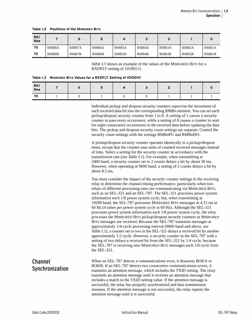
I.3
Date Code 20150130 Instruction Manual SEL-787 Relay
MIRRORED BITS CommunicationsOperation
Table I.3 shows an example of the values of the MIRRORED BITS for a RXDFLT setting of 10100111.
Individual pickup and dropout security counters supervise the movement of each received data bit into the corresponding RMBn element. You can set each pickup/dropout security counter from 1 to 8. A setting of 1 causes a security counter to pass every occurrence, while a setting of 8 causes a counter to wait for eight consecutive occurrences in the received data before updating the data bits. The pickup and dropout security count settings are separate. Control the security count settings with the settings RMBnPU and RMBnDO.
A pickup/dropout security counter operates identically to a pickup/dropout timer, except that the counter uses units of counted received messages instead of time. Select a setting for the security counter in accordance with the transmission rate (see Table I.1). For example, when transmitting at 2400 baud, a security counter set to 2 counts delays a bit by about 30 ms. However, when operating at 9600 baud, a setting of 2 counts delays a bit by about 8.5 ms.
You must consider the impact of the security counter settings in the receiving relay to determine the channel timing performance, particularly when two relays of different processing rates are communicating via MIRRORED BITS, such as an SEL-321 and an SEL-787. The SEL-321 processes power system information each 1/8 power system cycle, but, when transmitting at 19200 baud, the SEL-787 processes MIRRORED BITS messages at 4.15 ms at 60 Hz (4 times per power system cycle at 60 Hz). Although the SEL-321 processes power system information each 1/8 power system cycle, the relay processes the MIRRORED BITS pickup/dropout security counters as MIRRORED BITS messages are received. Because the SEL-787 transmits messages at approximately 1/4-cycle processing interval (9600 baud and above, see Table I.1), a counter set to two in the SEL-321 delays a received bit by another approximately 1/2 cycle. However, a security counter in the SEL-787 with a setting of two delays a received bit from the SEL-321 by 1/4 cycle, because the SEL-787 is receiving new MIRRORED BITS messages each 1/8 cycle from the SEL-321.
Channel Synchronization
When an SEL-787 detects a communications error, it deasserts ROKA or ROKB. If an SEL-787 detects two consecutive communications errors, it transmits an attention message, which includes the TXID setting. The relay transmits an attention message until it receives an attention message that includes a match to the TXID setting value. If the attention message is successful, the relay has properly synchronized and data transmission resumes. If the attention message is not successful, the relay repeats the attention message until it is successful.
Table I.2 Positions of the MIRRORED BITS
Bit/Row
7 6 5 4 3 2 1 0
70 RMB8A RMB7A RMB6A RMB5A RMB4A RMB3A RMB2A RMB1A
72 RMB8B RMB7B RMB6B RMB5B RMB4B RMB3B RMB2B RMB1B
Table I.3 MIRRORED BITS Values for a RXDFLT Setting of 10100111
Bit/Row
7 6 5 4 3 2 1 0
70 1 0 1 0 0 1 1 1
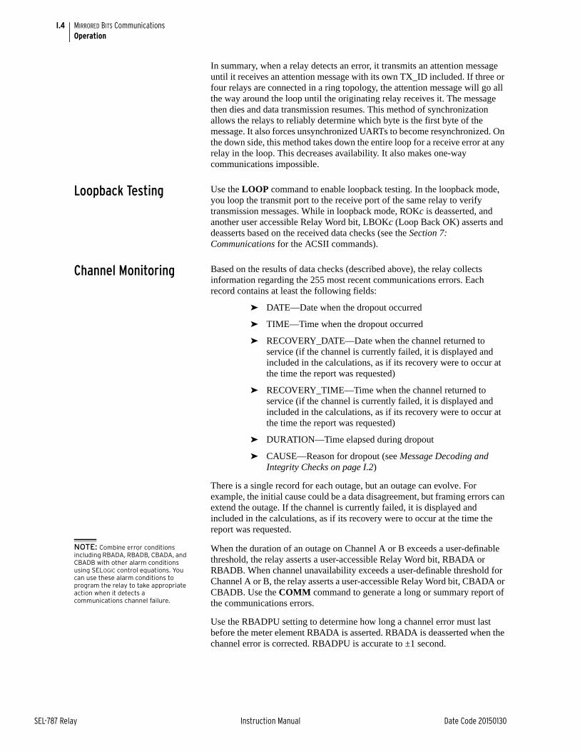
I.4
SEL-787 Relay Instruction Manual Date Code 20150130
MIRRORED BITS CommunicationsOperation
In summary, when a relay detects an error, it transmits an attention message until it receives an attention message with its own TX_ID included. If three or four relays are connected in a ring topology, the attention message will go all the way around the loop until the originating relay receives it. The message then dies and data transmission resumes. This method of synchronization allows the relays to reliably determine which byte is the first byte of the message. It also forces unsynchronized UARTs to become resynchronized. On the down side, this method takes down the entire loop for a receive error at any relay in the loop. This decreases availability. It also makes one-way communications impossible.
Loopback Testing Use the LOOP command to enable loopback testing. In the loopback mode, you loop the transmit port to the receive port of the same relay to verify transmission messages. While in loopback mode, ROKc is deasserted, and another user accessible Relay Word bit, LBOKc (Loop Back OK) asserts and deasserts based on the received data checks (see the Section 7: Communications for the ACSII commands).
Channel Monitoring Based on the results of data checks (described above), the relay collects information regarding the 255 most recent communications errors. Each record contains at least the following fields:
➤ DATE—Date when the dropout occurred
➤ TIME—Time when the dropout occurred
➤ RECOVERY_DATE—Date when the channel returned to service (if the channel is currently failed, it is displayed and included in the calculations, as if its recovery were to occur at the time the report was requested)
➤ RECOVERY_TIME—Time when the channel returned to service (if the channel is currently failed, it is displayed and included in the calculations, as if its recovery were to occur at the time the report was requested)
➤ DURATION—Time elapsed during dropout
➤ CAUSE—Reason for dropout (see Message Decoding and Integrity Checks on page I.2)
There is a single record for each outage, but an outage can evolve. For example, the initial cause could be a data disagreement, but framing errors can extend the outage. If the channel is currently failed, it is displayed and included in the calculations, as if its recovery were to occur at the time the report was requested.
NOTE: Combine error conditions including RBADA, RBADB, CBADA, and CBADB with other alarm conditions using SELOGIC control equations. You can use these alarm conditions to program the relay to take appropriate action when it detects a communications channel failure.
When the duration of an outage on Channel A or B exceeds a user-definable threshold, the relay asserts a user-accessible Relay Word bit, RBADA or RBADB. When channel unavailability exceeds a user-definable threshold for Channel A or B, the relay asserts a user-accessible Relay Word bit, CBADA or CBADB. Use the COMM command to generate a long or summary report of the communications errors.
Use the RBADPU setting to determine how long a channel error must last before the meter element RBADA is asserted. RBADA is deasserted when the channel error is corrected. RBADPU is accurate to ±1 second.
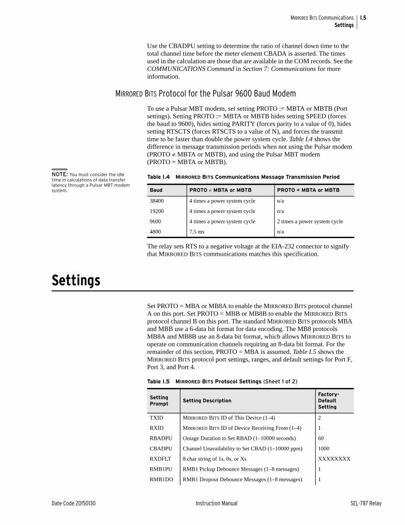
I.5
Date Code 20150130 Instruction Manual SEL-787 Relay
MIRRORED BITS CommunicationsSettings
Use the CBADPU setting to determine the ratio of channel down time to the total channel time before the meter element CBADA is asserted. The times used in the calculation are those that are available in the COM records. See the COMMUNICATIONS Command in Section 7: Communications for more information.
MIRRORED BITS Protocol for the Pulsar 9600 Baud Modem
To use a Pulsar MBT modem, set setting PROTO := MBTA or MBTB (Port settings). Setting PROTO := MBTA or MBTB hides setting SPEED (forces the baud to 9600), hides setting PARITY (forces parity to a value of 0), hides setting RTSCTS (forces RTSCTS to a value of N), and forces the transmit time to be faster than double the power system cycle. Table I.4 shows the difference in message transmission periods when not using the Pulsar modem (PROTO MBTA or MBTB), and using the Pulsar MBT modem (PROTO = MBTA or MBTB).
NOTE: You must consider the idle time in calculations of data transfer latency through a Pulsar MBT modem system.
The relay sets RTS to a negative voltage at the EIA-232 connector to signify that MIRRORED BITS communications matches this specification.
Settings
Set PROTO = MBA or MB8A to enable the MIRRORED BITS protocol channel A on this port. Set PROTO = MBB or MB8B to enable the MIRRORED BITS protocol channel B on this port. The standard MIRRORED BITS protocols MBA and MBB use a 6-data bit format for data encoding. The MB8 protocols MB8A and MB8B use an 8-data bit format, which allows MIRRORED BITS to operate on communication channels requiring an 8-data bit format. For the remainder of this section, PROTO = MBA is assumed. Table I.5 shows the MIRRORED BITS protocol port settings, ranges, and default settings for Port F, Port 3, and Port 4.
Table I.4 MIRRORED BITS Communications Message Transmission Period
Baud PROTO MBTA or MBTB PROTO = MBTA or MBTB
38400 4 times a power system cycle n/a
19200 4 times a power system cycle n/a
9600 4 times a power system cycle 2 times a power system cycle
4800 7.5 ms n/a
Table I.5 MIRRORED BITS Protocol Settings (Sheet 1 of 2)
Setting Prompt
Setting DescriptionFactory-Default Setting
TXID MIRRORED BITS ID of This Device (1–4) 2
RXID MIRRORED BITS ID of Device Receiving From (1–4) 1
RBADPU Outage Duration to Set RBAD (1–10000 seconds) 60
CBADPU Channel Unavailability to Set CBAD (1–10000 ppm) 1000
RXDFLT 8 char string of 1s, 0s, or Xs XXXXXXXX
RMB1PU RMB1 Pickup Debounce Messages (1–8 messages) 1
RMB1DO RMB1 Dropout Debounce Messages (1–8 messages) 1
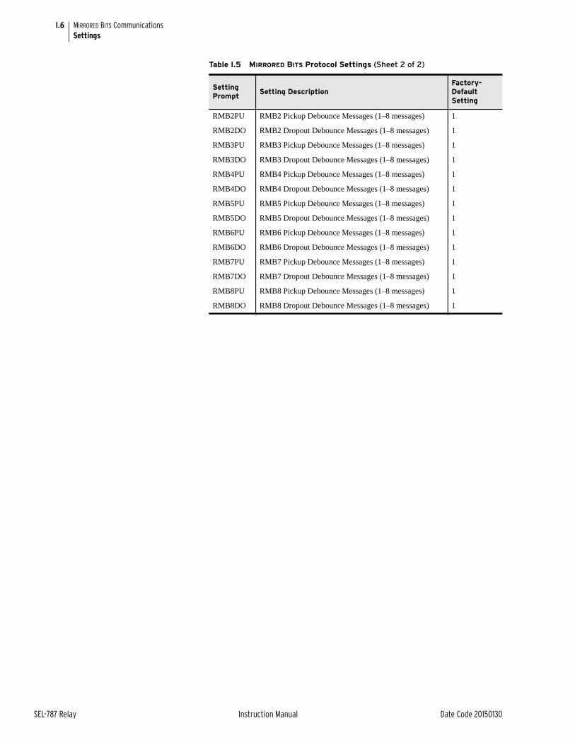
I.6
SEL-787 Relay Instruction Manual Date Code 20150130
MIRRORED BITS CommunicationsSettings
RMB2PU RMB2 Pickup Debounce Messages (1–8 messages) 1
RMB2DO RMB2 Dropout Debounce Messages (1–8 messages) 1
RMB3PU RMB3 Pickup Debounce Messages (1–8 messages) 1
RMB3DO RMB3 Dropout Debounce Messages (1–8 messages) 1
RMB4PU RMB4 Pickup Debounce Messages (1–8 messages) 1
RMB4DO RMB4 Dropout Debounce Messages (1–8 messages) 1
RMB5PU RMB5 Pickup Debounce Messages (1–8 messages) 1
RMB5DO RMB5 Dropout Debounce Messages (1–8 messages) 1
RMB6PU RMB6 Pickup Debounce Messages (1–8 messages) 1
RMB6DO RMB6 Dropout Debounce Messages (1–8 messages) 1
RMB7PU RMB7 Pickup Debounce Messages (1–8 messages) 1
RMB7DO RMB7 Dropout Debounce Messages (1–8 messages) 1
RMB8PU RMB8 Pickup Debounce Messages (1–8 messages) 1
RMB8DO RMB8 Dropout Debounce Messages (1–8 messages) 1
Table I.5 MIRRORED BITS Protocol Settings (Sheet 2 of 2)
Setting Prompt
Setting DescriptionFactory-Default Setting
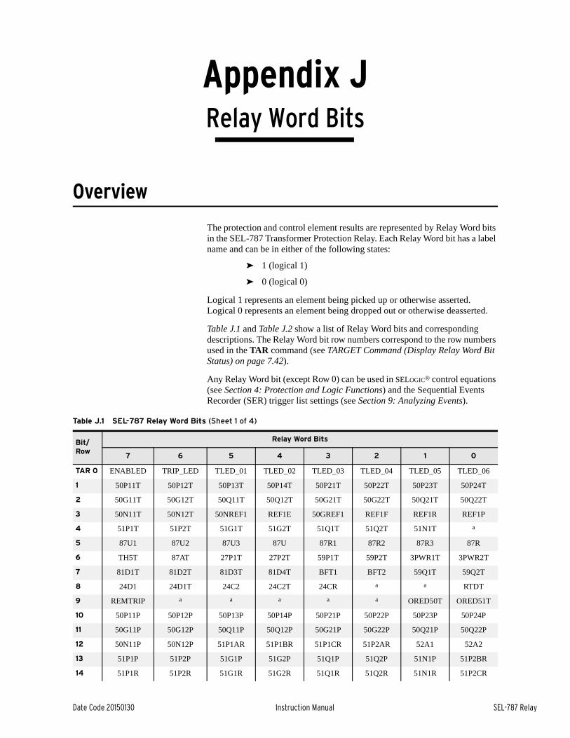
Date Code 20150130 Instruction Manual SEL-787 Relay
Appendix JRelay Word Bits
Instruction Manual
Overview
The protection and control element results are represented by Relay Word bits in the SEL-787 Transformer Protection Relay. Each Relay Word bit has a label name and can be in either of the following states:
➤ 1 (logical 1)
➤ 0 (logical 0)
Logical 1 represents an element being picked up or otherwise asserted. Logical 0 represents an element being dropped out or otherwise deasserted.
Table J.1 and Table J.2 show a list of Relay Word bits and corresponding descriptions. The Relay Word bit row numbers correspond to the row numbers used in the TAR command (see TARGET Command (Display Relay Word Bit Status) on page 7.42).
Any Relay Word bit (except Row 0) can be used in SELOGIC® control equations (see Section 4: Protection and Logic Functions) and the Sequential Events Recorder (SER) trigger list settings (see Section 9: Analyzing Events).
Table J.1 SEL-787 Relay Word Bits (Sheet 1 of 4)
Bit/ Row
Relay Word Bits
7 6 5 4 3 2 1 0
TAR 0 ENABLED TRIP_LED TLED_01 TLED_02 TLED_03 TLED_04 TLED_05 TLED_06
1 50P11T 50P12T 50P13T 50P14T 50P21T 50P22T 50P23T 50P24T
2 50G11T 50G12T 50Q11T 50Q12T 50G21T 50G22T 50Q21T 50Q22T
3 50N11T 50N12T 50NREF1 REF1E 50GREF1 REF1F REF1R REF1P
4 51P1T 51P2T 51G1T 51G2T 51Q1T 51Q2T 51N1T a
5 87U1 87U2 87U3 87U 87R1 87R2 87R3 87R
6 TH5T 87AT 27P1T 27P2T 59P1T 59P2T 3PWR1T 3PWR2T
7 81D1T 81D2T 81D3T 81D4T BFT1 BFT2 59Q1T 59Q2T
8 24D1 24D1T 24C2 24C2T 24CR a a RTDT
9 REMTRIP a a a a a ORED50T ORED51T
10 50P11P 50P12P 50P13P 50P14P 50P21P 50P22P 50P23P 50P24P
11 50G11P 50G12P 50Q11P 50Q12P 50G21P 50G22P 50Q21P 50Q22P
12 50N11P 50N12P 51P1AR 51P1BR 51P1CR 51P2AR 52A1 52A2
13 51P1P 51P2P 51G1P 51G2P 51Q1P 51Q2P 51N1P 51P2BR
14 51P1R 51P2R 51G1R 51G2R 51Q1R 51Q2R 51N1R 51P2CR
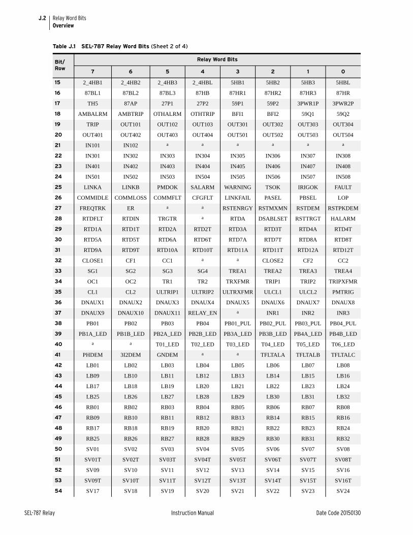
J.2
SEL-787 Relay Instruction Manual Date Code 20150130
Relay Word BitsOverview
15 2_4HB1 2_4HB2 2_4HB3 2_4HBL 5HB1 5HB2 5HB3 5HBL
16 87BL1 87BL2 87BL3 87HB 87HR1 87HR2 87HR3 87HR
17 TH5 87AP 27P1 27P2 59P1 59P2 3PWR1P 3PWR2P
18 AMBALRM AMBTRIP OTHALRM OTHTRIP BFI1 BFI2 59Q1 59Q2
19 TRIP OUT101 OUT102 OUT103 OUT301 OUT302 OUT303 OUT304
20 OUT401 OUT402 OUT403 OUT404 OUT501 OUT502 OUT503 OUT504
21 IN101 IN102 a a a a a a
22 IN301 IN302 IN303 IN304 IN305 IN306 IN307 IN308
23 IN401 IN402 IN403 IN404 IN405 IN406 IN407 IN408
24 IN501 IN502 IN503 IN504 IN505 IN506 IN507 IN508
25 LINKA LINKB PMDOK SALARM WARNING TSOK IRIGOK FAULT
26 COMMIDLE COMMLOSS COMMFLT CFGFLT LINKFAIL PASEL PBSEL LOP
27 FREQTRK ER a a RSTENRGY RSTMXMN RSTDEM RSTPKDEM
28 RTDFLT RTDIN TRGTR a RTDA DSABLSET RSTTRGT HALARM
29 RTD1A RTD1T RTD2A RTD2T RTD3A RTD3T RTD4A RTD4T
30 RTD5A RTD5T RTD6A RTD6T RTD7A RTD7T RTD8A RTD8T
31 RTD9A RTD9T RTD10A RTD10T RTD11A RTD11T RTD12A RTD12T
32 CLOSE1 CF1 CC1 a a CLOSE2 CF2 CC2
33 SG1 SG2 SG3 SG4 TREA1 TREA2 TREA3 TREA4
34 OC1 OC2 TR1 TR2 TRXFMR TRIP1 TRIP2 TRIPXFMR
35 CL1 CL2 ULTRIP1 ULTRIP2 ULTRXFMR ULCL1 ULCL2 PMTRIG
36 DNAUX1 DNAUX2 DNAUX3 DNAUX4 DNAUX5 DNAUX6 DNAUX7 DNAUX8
37 DNAUX9 DNAUX10 DNAUX11 RELAY_EN a INR1 INR2 INR3
38 PB01 PB02 PB03 PB04 PB01_PUL PB02_PUL PB03_PUL PB04_PUL
39 PB1A_LED PB1B_LED PB2A_LED PB2B_LED PB3A_LED PB3B_LED PB4A_LED PB4B_LED
40 a a T01_LED T02_LED T03_LED T04_LED T05_LED T06_LED
41 PHDEM 3I2DEM GNDEM a a TFLTALA TFLTALB TFLTALC
42 LB01 LB02 LB03 LB04 LB05 LB06 LB07 LB08
43 LB09 LB10 LB11 LB12 LB13 LB14 LB15 LB16
44 LB17 LB18 LB19 LB20 LB21 LB22 LB23 LB24
45 LB25 LB26 LB27 LB28 LB29 LB30 LB31 LB32
46 RB01 RB02 RB03 RB04 RB05 RB06 RB07 RB08
47 RB09 RB10 RB11 RB12 RB13 RB14 RB15 RB16
48 RB17 RB18 RB19 RB20 RB21 RB22 RB23 RB24
49 RB25 RB26 RB27 RB28 RB29 RB30 RB31 RB32
50 SV01 SV02 SV03 SV04 SV05 SV06 SV07 SV08
51 SV01T SV02T SV03T SV04T SV05T SV06T SV07T SV08T
52 SV09 SV10 SV11 SV12 SV13 SV14 SV15 SV16
53 SV09T SV10T SV11T SV12T SV13T SV14T SV15T SV16T
54 SV17 SV18 SV19 SV20 SV21 SV22 SV23 SV24
Table J.1 SEL-787 Relay Word Bits (Sheet 2 of 4)
Bit/ Row
Relay Word Bits
7 6 5 4 3 2 1 0
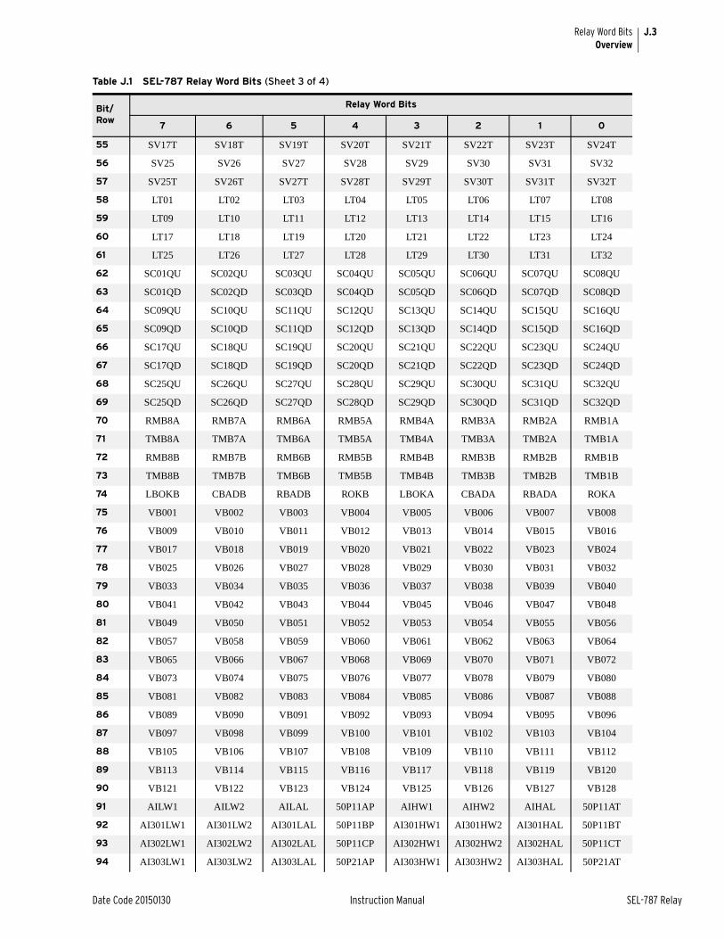
J.3
Date Code 20150130 Instruction Manual SEL-787 Relay
Relay Word BitsOverview
55 SV17T SV18T SV19T SV20T SV21T SV22T SV23T SV24T
56 SV25 SV26 SV27 SV28 SV29 SV30 SV31 SV32
57 SV25T SV26T SV27T SV28T SV29T SV30T SV31T SV32T
58 LT01 LT02 LT03 LT04 LT05 LT06 LT07 LT08
59 LT09 LT10 LT11 LT12 LT13 LT14 LT15 LT16
60 LT17 LT18 LT19 LT20 LT21 LT22 LT23 LT24
61 LT25 LT26 LT27 LT28 LT29 LT30 LT31 LT32
62 SC01QU SC02QU SC03QU SC04QU SC05QU SC06QU SC07QU SC08QU
63 SC01QD SC02QD SC03QD SC04QD SC05QD SC06QD SC07QD SC08QD
64 SC09QU SC10QU SC11QU SC12QU SC13QU SC14QU SC15QU SC16QU
65 SC09QD SC10QD SC11QD SC12QD SC13QD SC14QD SC15QD SC16QD
66 SC17QU SC18QU SC19QU SC20QU SC21QU SC22QU SC23QU SC24QU
67 SC17QD SC18QD SC19QD SC20QD SC21QD SC22QD SC23QD SC24QD
68 SC25QU SC26QU SC27QU SC28QU SC29QU SC30QU SC31QU SC32QU
69 SC25QD SC26QD SC27QD SC28QD SC29QD SC30QD SC31QD SC32QD
70 RMB8A RMB7A RMB6A RMB5A RMB4A RMB3A RMB2A RMB1A
71 TMB8A TMB7A TMB6A TMB5A TMB4A TMB3A TMB2A TMB1A
72 RMB8B RMB7B RMB6B RMB5B RMB4B RMB3B RMB2B RMB1B
73 TMB8B TMB7B TMB6B TMB5B TMB4B TMB3B TMB2B TMB1B
74 LBOKB CBADB RBADB ROKB LBOKA CBADA RBADA ROKA
75 VB001 VB002 VB003 VB004 VB005 VB006 VB007 VB008
76 VB009 VB010 VB011 VB012 VB013 VB014 VB015 VB016
77 VB017 VB018 VB019 VB020 VB021 VB022 VB023 VB024
78 VB025 VB026 VB027 VB028 VB029 VB030 VB031 VB032
79 VB033 VB034 VB035 VB036 VB037 VB038 VB039 VB040
80 VB041 VB042 VB043 VB044 VB045 VB046 VB047 VB048
81 VB049 VB050 VB051 VB052 VB053 VB054 VB055 VB056
82 VB057 VB058 VB059 VB060 VB061 VB062 VB063 VB064
83 VB065 VB066 VB067 VB068 VB069 VB070 VB071 VB072
84 VB073 VB074 VB075 VB076 VB077 VB078 VB079 VB080
85 VB081 VB082 VB083 VB084 VB085 VB086 VB087 VB088
86 VB089 VB090 VB091 VB092 VB093 VB094 VB095 VB096
87 VB097 VB098 VB099 VB100 VB101 VB102 VB103 VB104
88 VB105 VB106 VB107 VB108 VB109 VB110 VB111 VB112
89 VB113 VB114 VB115 VB116 VB117 VB118 VB119 VB120
90 VB121 VB122 VB123 VB124 VB125 VB126 VB127 VB128
91 AILW1 AILW2 AILAL 50P11AP AIHW1 AIHW2 AIHAL 50P11AT
92 AI301LW1 AI301LW2 AI301LAL 50P11BP AI301HW1 AI301HW2 AI301HAL 50P11BT
93 AI302LW1 AI302LW2 AI302LAL 50P11CP AI302HW1 AI302HW2 AI302HAL 50P11CT
94 AI303LW1 AI303LW2 AI303LAL 50P21AP AI303HW1 AI303HW2 AI303HAL 50P21AT
Table J.1 SEL-787 Relay Word Bits (Sheet 3 of 4)
Bit/ Row
Relay Word Bits
7 6 5 4 3 2 1 0

J.4
SEL-787 Relay Instruction Manual Date Code 20150130
Relay Word BitsDefinitions
Definitions
95 AI304LW1 AI304LW2 AI304LAL 50P21BP AI304HW1 AI304HW2 AI304HAL 50P21BT
96 AI401LW1 AI401LW2 AI401LAL 50P21CP AI401HW1 AI401HW2 AI401HAL 50P21CT
97 AI402LW1 AI402LW2 AI402LAL 51P1AP AI402HW1 AI402HW2 AI402HAL 51P1AT
98 AI403LW1 AI403LW2 AI403LAL 51P1BP AI403HW1 AI403HW2 AI403HAL 51P1BT
99 AI404LW1 AI404LW2 AI404LAL 51P1CP AI404HW1 AI404HW2 AI404HAL 51P1CT
100 AI501LW1 AI501LW2 AI501LAL 51P2AP AI501HW1 AI501HW2 AI501HAL 51P2AT
101 AI502LW1 AI502LW2 AI502LAL 51P2BP AI502HW1 AI502HW2 AI502HAL 51P2BT
102 AI503LW1 AI503LW2 AI503LAL 51P2CP AI503HW1 AI503HW2 AI503HAL 51P2CT
103 AI504LW1 AI504LW2 AI504LAL a AI504HW1 AI504HW2 AI504HAL a
104 DI_A1 DI_B1 DI_C1 DI_A2 DI_B2 DI_C2 a MATHERR
105 TQUAL1 TQUAL2 TQUAL4 TQUAL8 DST DSTP LPSEC LPSECP
106 TSNTPB TSNTPP TUTCS TUTC1 TUTC2 TUTC4 TUTC8 TUTCH
a Reserved for future use.
Table J.1 SEL-787 Relay Word Bits (Sheet 4 of 4)
Bit/ Row
Relay Word Bits
7 6 5 4 3 2 1 0
Table J.2 Relay Word Bit Definitions for the SEL-787 (Sheet 1 of 10)
Bit Definition Row
a Reserved —
2_4HB1 Second or Fourth Harmonic block asserted for differential element 1 15
2_4HB2 Second or Fourth Harmonic block asserted for differential element 2 15
2_4HB3 Second or Fourth Harmonic block asserted for differential element 3 15
2_4HBL Second or Fourth Harmonic block asserted (2_4HB1 OR 2_4HB2 OR 2_4HB3) 15
24C2 Level 2 Volts/Hertz composite element pickup 8
24C2T Level 2 Volts/Hertz composite element timed out 8
24CR Level 2 Volts/Hertz element fully reset 8
24D1 Level 1 Volts/Hertz instantaneous pickup 8
24D1T Level 1 Volts/Hertz definite-time element timed out 8
27P1 Level 1 phase undervoltage element pickup 17
27P1T Level 1 phase undervoltage element trip 6
27P2 Level 2 phase undervoltage element pickup 17
27P2T Level 2 phase undervoltage element trip 6
3I2DEM Negative-sequence current demand pickup 41
3PWR1P Three phase power element 1 pickup 17
3PWR1T Three phase power element 1 trip 6
3PWR2P Three phase power element 2 pickup 17
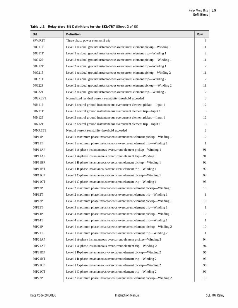
J.5
Date Code 20150130 Instruction Manual SEL-787 Relay
Relay Word BitsDefinitions
3PWR2T Three phase power element 2 trip 6
50G11P Level 1 residual ground instantaneous overcurrent element pickup—Winding 1 11
50G11T Level 1 residual ground instantaneous overcurrent element trip—Winding 1 2
50G12P Level 2 residual ground instantaneous overcurrent element pickup —Winding 1 11
50G12T Level 2 residual ground instantaneous overcurrent element trip—Winding 1 2
50G21P Level 1 residual ground instantaneous overcurrent element pickup—Winding 2 11
50G21T Level 1 residual ground instantaneous overcurrent element trip—Winding 2 2
50G22P Level 2 residual ground instantaneous overcurrent element pickup —Winding 2 11
50G22T Level 2 residual ground instantaneous overcurrent element trip—Winding 2 2
50GREF1 Normalized residual current sensitivity threshold exceeded 3
50N11P Level 1 neutral ground instantaneous overcurrent element pickup—Input 1 12
50N11T Level 1 neutral ground instantaneous overcurrent element trip—Input 1 3
50N12P Level 2 neutral ground instantaneous overcurrent element pickup—Input 1 12
50N12T Level 2 neutral ground instantaneous overcurrent element trip—Input 1 3
50NREF1 Neutral current sensitivity threshold exceeded 3
50P11P Level 1 maximum phase instantaneous overcurrent element pickup—Winding 1 10
50P11T Level 1 maximum phase instantaneous overcurrent element trip—Winding 1 1
50P11AP Level 1 A-phase instantaneous overcurrent element pickup—Winding 1 91
50P11AT Level 1 A-phase instantaneous overcurrent element trip—Winding 1 91
50P11BP Level 1 B-phase instantaneous overcurrent element pickup—Winding 1 92
50P11BT Level 1 B-phase instantaneous overcurrent element trip—Winding 1 92
50P11CP Level 1 C-phase instantaneous overcurrent element pickup—Winding 1 93
50P11CT Level 1 C-phase instantaneous overcurrent element trip—Winding 1 93
50P12P Level 2 maximum phase instantaneous overcurrent element pickup—Winding 1 10
50P12T Level 2 maximum phase instantaneous overcurrent element trip—Winding 1 1
50P13P Level 3 maximum phase instantaneous overcurrent element pickup—Winding 1 10
50P13T Level 3 maximum phase instantaneous overcurrent element trip—Winding 1 1
50P14P Level 4 maximum phase instantaneous overcurrent element pickup—Winding 1 10
50P14T Level 4 maximum phase instantaneous overcurrent element trip—Winding 1 1
50P21P Level 1 maximum phase instantaneous overcurrent element pickup—Winding 2 10
50P21T Level 1 maximum phase instantaneous overcurrent element trip—Winding 2 1
50P21AP Level 1 A-phase instantaneous overcurrent element pickup—Winding 2 94
50P21AT Level 1 A-phase instantaneous overcurrent element trip—Winding 2 94
50P21BP Level 1 B-phase instantaneous overcurrent element pickup—Winding 2 95
50P21BT Level 1 B-phase instantaneous overcurrent element trip—Winding 2 95
50P21CP Level 1 C-phase instantaneous overcurrent element pickup—Winding 2 96
50P21CT Level 1 C-phase instantaneous overcurrent element trip—Winding 2 96
50P22P Level 2 maximum phase instantaneous overcurrent element pickup—Winding 2 10
Table J.2 Relay Word Bit Definitions for the SEL-787 (Sheet 2 of 10)
Bit Definition Row
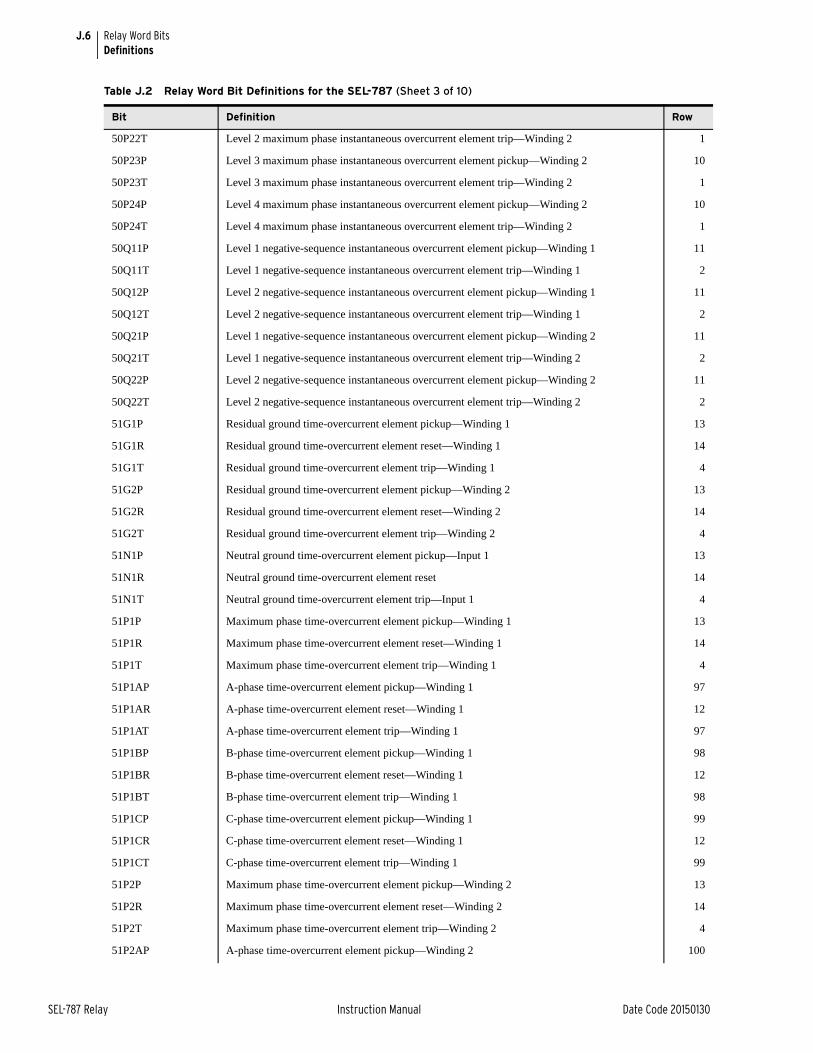
J.6
SEL-787 Relay Instruction Manual Date Code 20150130
Relay Word BitsDefinitions
50P22T Level 2 maximum phase instantaneous overcurrent element trip—Winding 2 1
50P23P Level 3 maximum phase instantaneous overcurrent element pickup—Winding 2 10
50P23T Level 3 maximum phase instantaneous overcurrent element trip—Winding 2 1
50P24P Level 4 maximum phase instantaneous overcurrent element pickup—Winding 2 10
50P24T Level 4 maximum phase instantaneous overcurrent element trip—Winding 2 1
50Q11P Level 1 negative-sequence instantaneous overcurrent element pickup—Winding 1 11
50Q11T Level 1 negative-sequence instantaneous overcurrent element trip—Winding 1 2
50Q12P Level 2 negative-sequence instantaneous overcurrent element pickup—Winding 1 11
50Q12T Level 2 negative-sequence instantaneous overcurrent element trip—Winding 1 2
50Q21P Level 1 negative-sequence instantaneous overcurrent element pickup—Winding 2 11
50Q21T Level 1 negative-sequence instantaneous overcurrent element trip—Winding 2 2
50Q22P Level 2 negative-sequence instantaneous overcurrent element pickup—Winding 2 11
50Q22T Level 2 negative-sequence instantaneous overcurrent element trip—Winding 2 2
51G1P Residual ground time-overcurrent element pickup—Winding 1 13
51G1R Residual ground time-overcurrent element reset—Winding 1 14
51G1T Residual ground time-overcurrent element trip—Winding 1 4
51G2P Residual ground time-overcurrent element pickup—Winding 2 13
51G2R Residual ground time-overcurrent element reset—Winding 2 14
51G2T Residual ground time-overcurrent element trip—Winding 2 4
51N1P Neutral ground time-overcurrent element pickup—Input 1 13
51N1R Neutral ground time-overcurrent element reset 14
51N1T Neutral ground time-overcurrent element trip—Input 1 4
51P1P Maximum phase time-overcurrent element pickup—Winding 1 13
51P1R Maximum phase time-overcurrent element reset—Winding 1 14
51P1T Maximum phase time-overcurrent element trip—Winding 1 4
51P1AP A-phase time-overcurrent element pickup—Winding 1 97
51P1AR A-phase time-overcurrent element reset—Winding 1 12
51P1AT A-phase time-overcurrent element trip—Winding 1 97
51P1BP B-phase time-overcurrent element pickup—Winding 1 98
51P1BR B-phase time-overcurrent element reset—Winding 1 12
51P1BT B-phase time-overcurrent element trip—Winding 1 98
51P1CP C-phase time-overcurrent element pickup—Winding 1 99
51P1CR C-phase time-overcurrent element reset—Winding 1 12
51P1CT C-phase time-overcurrent element trip—Winding 1 99
51P2P Maximum phase time-overcurrent element pickup—Winding 2 13
51P2R Maximum phase time-overcurrent element reset—Winding 2 14
51P2T Maximum phase time-overcurrent element trip—Winding 2 4
51P2AP A-phase time-overcurrent element pickup—Winding 2 100
Table J.2 Relay Word Bit Definitions for the SEL-787 (Sheet 3 of 10)
Bit Definition Row
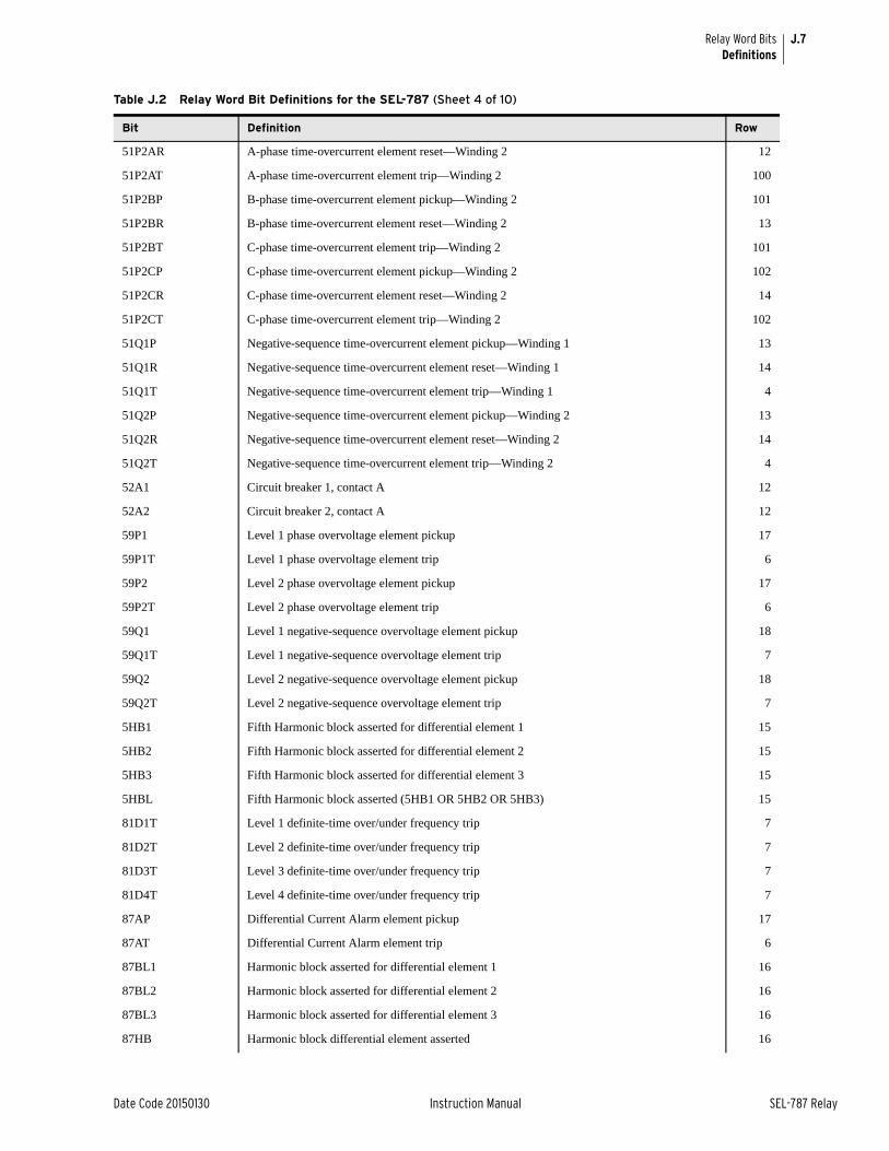
J.7
Date Code 20150130 Instruction Manual SEL-787 Relay
Relay Word BitsDefinitions
51P2AR A-phase time-overcurrent element reset—Winding 2 12
51P2AT A-phase time-overcurrent element trip—Winding 2 100
51P2BP B-phase time-overcurrent element pickup—Winding 2 101
51P2BR B-phase time-overcurrent element reset—Winding 2 13
51P2BT C-phase time-overcurrent element trip—Winding 2 101
51P2CP C-phase time-overcurrent element pickup—Winding 2 102
51P2CR C-phase time-overcurrent element reset—Winding 2 14
51P2CT C-phase time-overcurrent element trip—Winding 2 102
51Q1P Negative-sequence time-overcurrent element pickup—Winding 1 13
51Q1R Negative-sequence time-overcurrent element reset—Winding 1 14
51Q1T Negative-sequence time-overcurrent element trip—Winding 1 4
51Q2P Negative-sequence time-overcurrent element pickup—Winding 2 13
51Q2R Negative-sequence time-overcurrent element reset—Winding 2 14
51Q2T Negative-sequence time-overcurrent element trip—Winding 2 4
52A1 Circuit breaker 1, contact A 12
52A2 Circuit breaker 2, contact A 12
59P1 Level 1 phase overvoltage element pickup 17
59P1T Level 1 phase overvoltage element trip 6
59P2 Level 2 phase overvoltage element pickup 17
59P2T Level 2 phase overvoltage element trip 6
59Q1 Level 1 negative-sequence overvoltage element pickup 18
59Q1T Level 1 negative-sequence overvoltage element trip 7
59Q2 Level 2 negative-sequence overvoltage element pickup 18
59Q2T Level 2 negative-sequence overvoltage element trip 7
5HB1 Fifth Harmonic block asserted for differential element 1 15
5HB2 Fifth Harmonic block asserted for differential element 2 15
5HB3 Fifth Harmonic block asserted for differential element 3 15
5HBL Fifth Harmonic block asserted (5HB1 OR 5HB2 OR 5HB3) 15
81D1T Level 1 definite-time over/under frequency trip 7
81D2T Level 2 definite-time over/under frequency trip 7
81D3T Level 3 definite-time over/under frequency trip 7
81D4T Level 4 definite-time over/under frequency trip 7
87AP Differential Current Alarm element pickup 17
87AT Differential Current Alarm element trip 6
87BL1 Harmonic block asserted for differential element 1 16
87BL2 Harmonic block asserted for differential element 2 16
87BL3 Harmonic block asserted for differential element 3 16
87HB Harmonic block differential element asserted 16
Table J.2 Relay Word Bit Definitions for the SEL-787 (Sheet 4 of 10)
Bit Definition Row
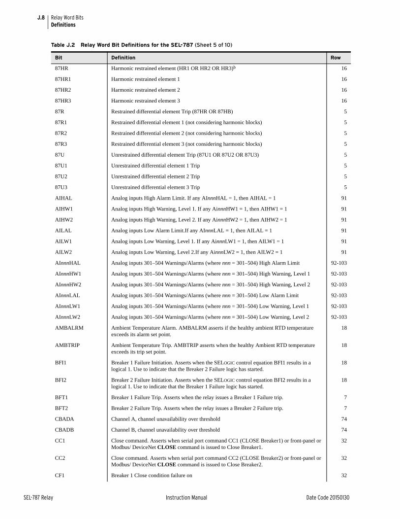
J.8
SEL-787 Relay Instruction Manual Date Code 20150130
Relay Word BitsDefinitions
87HR Harmonic restrained element (HR1 OR HR2 OR HR3)b 16
87HR1 Harmonic restrained element 1 16
87HR2 Harmonic restrained element 2 16
87HR3 Harmonic restrained element 3 16
87R Restrained differential element Trip (87HR OR 87HB) 5
87R1 Restrained differential element 1 (not considering harmonic blocks) 5
87R2 Restrained differential element 2 (not considering harmonic blocks) 5
87R3 Restrained differential element 3 (not considering harmonic blocks) 5
87U Unrestrained differential element Trip (87U1 OR 87U2 OR 87U3) 5
87U1 Unrestrained differential element 1 Trip 5
87U2 Unrestrained differential element 2 Trip 5
87U3 Unrestrained differential element 3 Trip 5
AIHAL Analog inputs High Alarm Limit. If any AInnnHAL = 1, then AIHAL = 1 91
AIHW1 Analog inputs High Warning, Level 1. If any AinnnHW1 = 1, then AIHW1 = 1 91
AIHW2 Analog inputs High Warning, Level 2. If any AinnnHW2 = 1, then AIHW2 = 1 91
AILAL Analog inputs Low Alarm Limit.If any AInnnLAL = 1, then AILAL = 1 91
AILW1 Analog inputs Low Warning, Level 1. If any AinnnLW1 = 1, then AILW1 = 1 91
AILW2 Analog inputs Low Warning, Level 2.If any AinnnLW2 = 1, then AILW2 = 1 91
AInnnHAL Analog inputs 301–504 Warnings/Alarms (where nnn = 301–504) High Alarm Limit 92-103
AInnnHW1 Analog inputs 301–504 Warnings/Alarms (where nnn = 301–504) High Warning, Level 1 92-103
AInnnHW2 Analog inputs 301–504 Warnings/Alarms (where nnn = 301–504) High Warning, Level 2 92-103
AInnnLAL Analog inputs 301–504 Warnings/Alarms (where nnn = 301–504) Low Alarm Limit 92-103
AInnnLW1 Analog inputs 301–504 Warnings/Alarms (where nnn = 301–504) Low Warning, Level 1 92-103
AInnnLW2 Analog inputs 301–504 Warnings/Alarms (where nnn = 301–504) Low Warning, Level 2 92-103
AMBALRM Ambient Temperature Alarm. AMBALRM asserts if the healthy ambient RTD temperature exceeds its alarm set point.
18
AMBTRIP Ambient Temperature Trip. AMBTRIP asserts when the healthy Ambient RTD temperature exceeds its trip set point.
18
BFI1 Breaker 1 Failure Initiation. Asserts when the SELOGIC control equation BFI1 results in a logical 1. Use to indicate that the Breaker 2 Failure logic has started.
18
BFI2 Breaker 2 Failure Initiation. Asserts when the SELOGIC control equation BFI2 results in a logical 1. Use to indicate that the Breaker 1 Failure logic has started.
18
BFT1 Breaker 1 Failure Trip. Asserts when the relay issues a Breaker 1 Failure trip. 7
BFT2 Breaker 2 Failure Trip. Asserts when the relay issues a Breaker 2 Failure trip. 7
CBADA Channel A, channel unavailability over threshold 74
CBADB Channel B, channel unavailability over threshold 74
CC1 Close command. Asserts when serial port command CC1 (CLOSE Breaker1) or front-panel or Modbus/ DeviceNet CLOSE command is issued to Close Breaker1.
32
CC2 Close command. Asserts when serial port command CC2 (CLOSE Breaker2) or front-panel or Modbus/ DeviceNet CLOSE command is issued to Close Breaker2.
32
CF1 Breaker 1 Close condition failure on 32
Table J.2 Relay Word Bit Definitions for the SEL-787 (Sheet 5 of 10)
Bit Definition Row
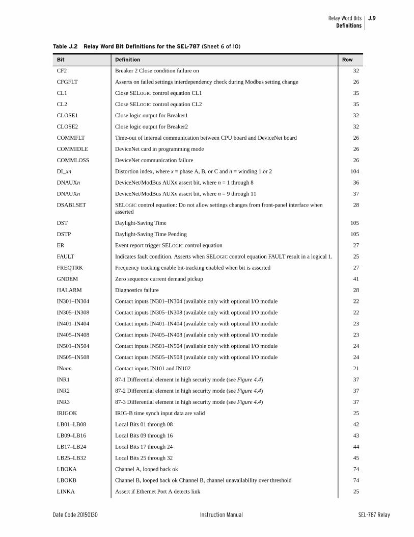
J.9
Date Code 20150130 Instruction Manual SEL-787 Relay
Relay Word BitsDefinitions
CF2 Breaker 2 Close condition failure on 32
CFGFLT Asserts on failed settings interdependency check during Modbus setting change 26
CL1 Close SELOGIC control equation CL1 35
CL2 Close SELOGIC control equation CL2 35
CLOSE1 Close logic output for Breaker1 32
CLOSE2 Close logic output for Breaker2 32
COMMFLT Time-out of internal communication between CPU board and DeviceNet board 26
COMMIDLE DeviceNet card in programming mode 26
COMMLOSS DeviceNet communication failure 26
DI_xn Distortion index, where x = phase A, B, or C and n = winding 1 or 2 104
DNAUXn DeviceNet/ModBus AUXn assert bit, where n = 1 through 8 36
DNAUXn DeviceNet/ModBus AUXn assert bit, where n = 9 through 11 37
DSABLSET SELOGIC control equation: Do not allow settings changes from front-panel interface when asserted
28
DST Daylight-Saving Time 105
DSTP Daylight-Saving Time Pending 105
ER Event report trigger SELOGIC control equation 27
FAULT Indicates fault condition. Asserts when SELOGIC control equation FAULT result in a logical 1. 25
FREQTRK Frequency tracking enable bit-tracking enabled when bit is asserted 27
GNDEM Zero sequence current demand pickup 41
HALARM Diagnostics failure 28
IN301–IN304 Contact inputs IN301–IN304 (available only with optional I/O module 22
IN305–IN308 Contact inputs IN305–IN308 (available only with optional I/O module 22
IN401–IN404 Contact inputs IN401–IN404 (available only with optional I/O module 23
IN405–IN408 Contact inputs IN405–IN408 (available only with optional I/O module 23
IN501–IN504 Contact inputs IN501–IN504 (available only with optional I/O module 24
IN505–IN508 Contact inputs IN505–IN508 (available only with optional I/O module 24
INnnn Contact inputs IN101 and IN102 21
INR1 87-1 Differential element in high security mode (see Figure 4.4) 37
INR2 87-2 Differential element in high security mode (see Figure 4.4) 37
INR3 87-3 Differential element in high security mode (see Figure 4.4) 37
IRIGOK IRIG-B time synch input data are valid 25
LB01–LB08 Local Bits 01 through 08 42
LB09–LB16 Local Bits 09 through 16 43
LB17–LB24 Local Bits 17 through 24 44
LB25–LB32 Local Bits 25 through 32 45
LBOKA Channel A, looped back ok 74
LBOKB Channel B, looped back ok Channel B, channel unavailability over threshold 74
LINKA Assert if Ethernet Port A detects link 25
Table J.2 Relay Word Bit Definitions for the SEL-787 (Sheet 6 of 10)
Bit Definition Row
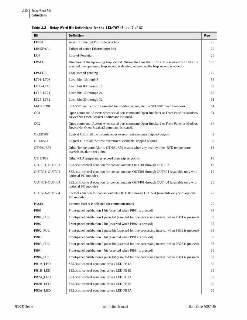
J.10
SEL-787 Relay Instruction Manual Date Code 20150130
Relay Word BitsDefinitions
LINKB Assert if Ethernet Port B detects link 25
LINKFAIL Failure of active Ethernet port link 26
LOP Loss-of-Potential 26
LPSEC Direction of the upcoming leap second. During the time that LPSECP is asserted, if LPSEC is asserted, the upcoming leap second is deleted; otherwise, the leap second is added.
105
LPSECP Leap second pending 105
LT01–LT08 Latch bits 1through 8 58
LT09–LT16 Latch bits 09 through 16 59
LT17–LT24 Latch bits 17 through 24 60
LT25–LT32 Latch bits 25 through 32 61
MATHERR SELOGIC math error bit asserted for divide-by-zero, etc., in SELOGIC math functions 104
OC1 Open command. Asserts when serial port command Open Breaker1 or Front Panel or Modbus/ DeviceNet Open Breaker1 command is issued.
34
OC2 Open command. Asserts when serial port command Open Breaker2 or Front Panel or Modbus/ DeviceNet Open Breaker2 command is issued.
34
ORED50T Logical OR of all the instantaneous overcurrent elements Tripped outputs 9
ORED51T Logical OR of all the time overcurrent elements Tripped outputs 9
OTHALRM Other Temperature Alarm. OTHALRM asserts when any healthy other RTD temperature exceeds its alarm set point.
18
OTHTRIP Other RTD temperatures exceed their trip set points 18
OUT101–OUT103 SELOGIC control equation for contact outputs OUT101 through OUT103 19
OUT301–OUT304 SELOGIC control equation for contact outputs OUT301 through OUT304 (available only with optional I/O module)
19
OUT401–OUT404 SELOGIC control equation for contact outputs OUT401 through OUT404 (available only with optional I/O module)
20
OUT501–OUT504 Control equation for contact outputs OUT501 through OUT504 (available only with optional I/O module)
20
PASEL Ethernet Port A is selected for communications 26
PB01 Front-panel pushbutton 1 bit (asserted when PB01 is pressed) 38
PB01_PUL Front-panel pushbutton 1 pulse bit (asserted for one processing interval when PB01 is pressed) 38
PB02 Front-panel pushbutton 2 bit (asserted when PB02 is pressed) 38
PB02_PUL Front-panel pushbutton 2 pulse bit (asserted for one processing interval when PB02 is pressed) 38
PB03 Front-panel pushbutton 3 bit (asserted when PB03 is pressed) 38
PB03_PUL Front-panel pushbutton 3 pulse bit (asserted for one processing interval when PB03 is pressed) 38
PB04 Front-panel pushbutton 4 bit (asserted when PB04 is pressed) 38
PB04_PUL Front-panel pushbutton 4 pulse bit (asserted for one processing interval when PB04 is pressed) 38
PB1A_LED SELOGIC control equation: drives LED PB1A 39
PB1B_LED SELOGIC control equation: drives LED PB1B 39
PB2A_LED SELOGIC control equation: drives LED PB2A 39
PB2B_LED SELOGIC control equation: drives LED PB2B 39
PB3A_LED SELOGIC control equation: drives LED PB3A 39
Table J.2 Relay Word Bit Definitions for the SEL-787 (Sheet 7 of 10)
Bit Definition Row
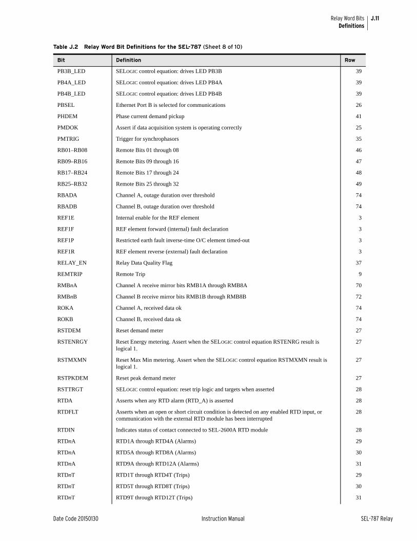
J.11
Date Code 20150130 Instruction Manual SEL-787 Relay
Relay Word BitsDefinitions
PB3B_LED SELOGIC control equation: drives LED PB3B 39
PB4A_LED SELOGIC control equation: drives LED PB4A 39
PB4B_LED SELOGIC control equation: drives LED PB4B 39
PBSEL Ethernet Port B is selected for communications 26
PHDEM Phase current demand pickup 41
PMDOK Assert if data acquisition system is operating correctly 25
PMTRIG Trigger for synchrophasors 35
RB01–RB08 Remote Bits 01 through 08 46
RB09–RB16 Remote Bits 09 through 16 47
RB17–RB24 Remote Bits 17 through 24 48
RB25–RB32 Remote Bits 25 through 32 49
RBADA Channel A, outage duration over threshold 74
RBADB Channel B, outage duration over threshold 74
REF1E Internal enable for the REF element 3
REF1F REF element forward (internal) fault declaration 3
REF1P Restricted earth fault inverse-time O/C element timed-out 3
REF1R REF element reverse (external) fault declaration 3
RELAY_EN Relay Data Quality Flag 37
REMTRIP Remote Trip 9
RMBnA Channel A receive mirror bits RMB1A through RMB8A 70
RMBnB Channel B receive mirror bits RMB1B through RMB8B 72
ROKA Channel A, received data ok 74
ROKB Channel B, received data ok 74
RSTDEM Reset demand meter 27
RSTENRGY Reset Energy metering. Assert when the SELOGIC control equation RSTENRG result is logical 1.
27
RSTMXMN Reset Max Min metering. Assert when the SELOGIC control equation RSTMXMN result is logical 1.
27
RSTPKDEM Reset peak demand meter 27
RSTTRGT SELOGIC control equation: reset trip logic and targets when asserted 28
RTDA Asserts when any RTD alarm (RTD_A) is asserted 28
RTDFLT Asserts when an open or short circuit condition is detected on any enabled RTD input, or communication with the external RTD module has been interrupted
28
RTDIN Indicates status of contact connected to SEL-2600A RTD module 28
RTDnA RTD1A through RTD4A (Alarms) 29
RTDnA RTD5A through RTD8A (Alarms) 30
RTDnA RTD9A through RTD12A (Alarms) 31
RTDnT RTD1T through RTD4T (Trips) 29
RTDnT RTD5T through RTD8T (Trips) 30
RTDnT RTD9T through RTD12T (Trips) 31
Table J.2 Relay Word Bit Definitions for the SEL-787 (Sheet 8 of 10)
Bit Definition Row

J.12
SEL-787 Relay Instruction Manual Date Code 20150130
Relay Word BitsDefinitions
RTDT Asserts when any RTD trip (RTD_T) is asserted 8
SALARM Software Alarms: invalid password, changing access levels, settings changes, active group changes, copy commands, and password changes
25
SCnnQD SELOGIC Counters 01 through 08 asserted when counter = 0 63
SCnnQD SELOGIC Counters 09 through 16 asserted when counter = 0 65
SCnnQD SELOGIC Counters 17 through 24 asserted when counter = 0 67
SCnnQD SELOGIC Counters 25 through 32 asserted when counter = 0 69
SCnnQU SELOGIC Counters 01 through 08 asserted when counter = preset value 62
SCnnQU SELOGIC Counters 09 through 16 asserted when counter = preset value 64
SCnnQU SELOGIC Counters 17 through 24 asserted when counter = preset value 66
SCnnQU SELOGIC Counters 25 through 32 asserted when counter = preset value 68
SG1 Asserts when setting group 1 is active 33
SG2 Asserts when setting group 2 is active 33
SG3 Asserts when setting group 3 is active 33
SG4 Asserts when setting group 4 is active 33
SV01–SV08 SELOGIC control equation variables SV01 through SV08 50
SV01T–SV08T SELOGIC control equation variable SV01T through SV08T with settable pickup and dropout time delay
51
SV09–SV16 SELOGIC control equation variables SV09 through SV16 52
SV09T–SV16T SELOGIC control equation variable SV09T through SV16T with settable pickup and dropout time delay
53
SV17–SV24 SELOGIC control equation variables SV17 through SV24 54
SV17T–SV24T SELOGIC control equation variable SV17T through SV24T with settable pickup and dropout time delay
55
SV25–SV32 SELOGIC control equation variables SV25 through SV32 56
SV25T–SV32T SELOGIC control equation variable SV25T through SV32T with settable pickup and dropout time delay
57
T01_LED–T06_LED SELOGIC control equation: drives T01_LED through T06_LED 40
TFLTALA Through fault alarm, phase A 41
TFLTALB Through fault alarm, phase B 41
TFLTALC Through fault alarm, phase C 41
TH5 Fifth Harmonic alarm threshold exceeded 17
TH5T Fifth Harmonic alarm threshold exceeded for longer than TH5D 6
TMBnA Channel A transmit mirror bits TMB1A through TMB8A 71
TMBnB Channel B transmit mirror bits TMB1B through TMB8B 73
TQUAL1 Time Quality Bit, add 1 when asserted 105
TQUAL2 Time Quality Bit, add 2 when asserted 105
TQUAL4 Time Quality Bit, add 4 when asserted 105
TQUAL8 Time Quality Bit, add 8 when asserted 105
TR1 Trip SELOGIC control equation TR1 (Also has been referred to as TRIPEQ1) 34
Table J.2 Relay Word Bit Definitions for the SEL-787 (Sheet 9 of 10)
Bit Definition Row
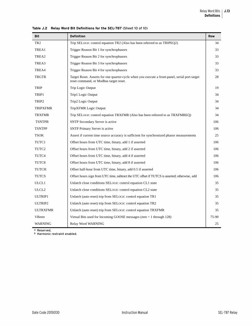
J.13
Date Code 20150130 Instruction Manual SEL-787 Relay
Relay Word BitsDefinitions
TR2 Trip SELOGIC control equation TR2 (Also has been referred to as TRIPEQ2) 34
TREA1 Trigger Reason Bit 1 for synchrophasors 33
TREA2 Trigger Reason Bit 2 for synchrophasors 33
TREA3 Trigger Reason Bit 3 for synchrophasors 33
TREA4 Trigger Reason Bit 4 for synchrophasors 33
TRGTR Target Reset. Asserts for one quarter-cycle when you execute a front-panel, serial port target reset command, or Modbus target reset.
28
TRIP Trip Logic Output 19
TRIP1 Trip1 Logic Output 34
TRIP2 Trip2 Logic Output 34
TRIPXFMR TripXFMR Logic Output 34
TRXFMR Trip SELOGIC control equation TRXFMR (Also has been referred to as TRXFMREQ) 34
TSNTPB SNTP Secondary Server is active 106
TSNTPP SNTP Primary Server is active 106
TSOK Assert if current time source accuracy is sufficient for synchronized phasor measurements 25
TUTC1 Offset hours from UTC time, binary, add 1 if asserted 106
TUTC2 Offset hours from UTC time, binary, add 2 if asserted 106
TUTC4 Offset hours from UTC time, binary, add 4 if asserted 106
TUTC8 Offset hours from UTC time, binary, add 8 if asserted 106
TUTCH Offset half-hour from UTC time, binary, add 0.5 if asserted 106
TUTCS Offset hours sign from UTC time, subtract the UTC offset if TUTCS is asserted; otherwise, add 106
ULCL1 Unlatch close conditions SELOGIC control equation CL1 state 35
ULCL2 Unlatch close conditions SELOGIC control equation CL2 state 35
ULTRIP1 Unlatch (auto reset) trip from SELOGIC control equation TR1 35
ULTRIP2 Unlatch (auto reset) trip from SELOGIC control equation TR2 35
ULTRXFMR Unlatch (auto reset) trip from SELOGIC control equation TRXFMR 35
VBnnn Virtual Bits used for Incoming GOOSE messages (nnn = 1 through 128) 75-90
WARNING Relay Word WARNING 25
a Reserved.b Harmonic restraint enabled.
Table J.2 Relay Word Bit Definitions for the SEL-787 (Sheet 10 of 10)
Bit Definition Row

This page intentionally left blank
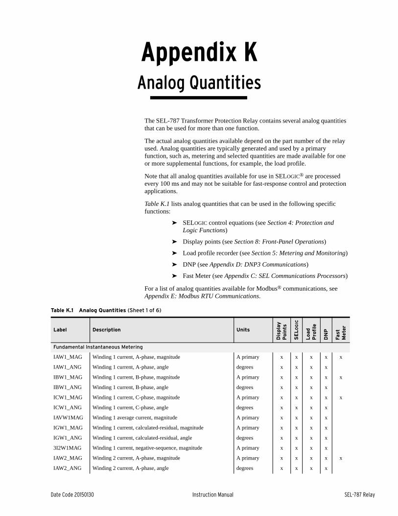
Date Code 20150130 Instruction Manual SEL-787 Relay
Appendix KAnalog Quantities
Instruction Manual
The SEL-787 Transformer Protection Relay contains several analog quantities that can be used for more than one function.
The actual analog quantities available depend on the part number of the relay used. Analog quantities are typically generated and used by a primary function, such as, metering and selected quantities are made available for one or more supplemental functions, for example, the load profile.
Note that all analog quantities available for use in SELOGIC® are processed every 100 ms and may not be suitable for fast-response control and protection applications.
Table K.1 lists analog quantities that can be used in the following specific functions:
➤ SELOGIC control equations (see Section 4: Protection and Logic Functions)
➤ Display points (see Section 8: Front-Panel Operations)
➤ Load profile recorder (see Section 5: Metering and Monitoring)
➤ DNP (see Appendix D: DNP3 Communications)
➤ Fast Meter (see Appendix C: SEL Communications Processors)
For a list of analog quantities available for Modbus® communications, see Appendix E: Modbus RTU Communications.
Table K.1 Analog Quantities (Sheet 1 of 6)
Label Description Units
Dis
pla
y
Poin
ts
SE
LO
GIC
Load
Pro
file
DN
P
Fast
M
eter
Fundamental Instantaneous Metering
IAW1_MAG Winding 1 current, A-phase, magnitude A primary x x x x x
IAW1_ANG Winding 1 current, A-phase, angle degrees x x x x
IBW1_MAG Winding 1 current, B-phase, magnitude A primary x x x x x
IBW1_ANG Winding 1 current, B-phase, angle degrees x x x x
ICW1_MAG Winding 1 current, C-phase, magnitude A primary x x x x x
ICW1_ANG Winding 1 current, C-phase, angle degrees x x x x
IAVW1MAG Winding 1 average current, magnitude A primary x x x x
IGW1_MAG Winding 1 current, calculated-residual, magnitude A primary x x x x
IGW1_ANG Winding 1 current, calculated-residual, angle degrees x x x x
3I2W1MAG Winding 1 current, negative-sequence, magnitude A primary x x x x
IAW2_MAG Winding 2 current, A-phase, magnitude A primary x x x x x
IAW2_ANG Winding 2 current, A-phase, angle degrees x x x x
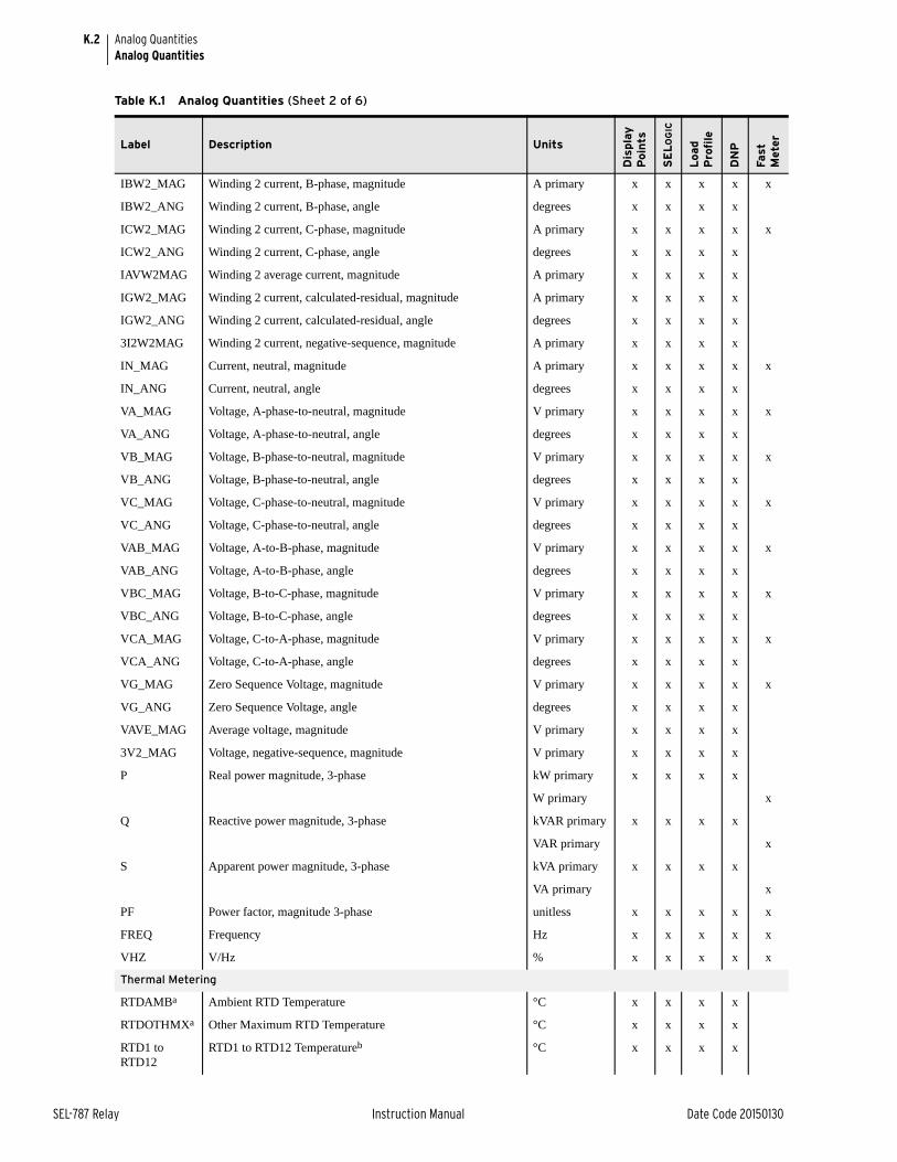
K.2
SEL-787 Relay Instruction Manual Date Code 20150130
Analog QuantitiesAnalog Quantities
IBW2_MAG Winding 2 current, B-phase, magnitude A primary x x x x x
IBW2_ANG Winding 2 current, B-phase, angle degrees x x x x
ICW2_MAG Winding 2 current, C-phase, magnitude A primary x x x x x
ICW2_ANG Winding 2 current, C-phase, angle degrees x x x x
IAVW2MAG Winding 2 average current, magnitude A primary x x x x
IGW2_MAG Winding 2 current, calculated-residual, magnitude A primary x x x x
IGW2_ANG Winding 2 current, calculated-residual, angle degrees x x x x
3I2W2MAG Winding 2 current, negative-sequence, magnitude A primary x x x x
IN_MAG Current, neutral, magnitude A primary x x x x x
IN_ANG Current, neutral, angle degrees x x x x
VA_MAG Voltage, A-phase-to-neutral, magnitude V primary x x x x x
VA_ANG Voltage, A-phase-to-neutral, angle degrees x x x x
VB_MAG Voltage, B-phase-to-neutral, magnitude V primary x x x x x
VB_ANG Voltage, B-phase-to-neutral, angle degrees x x x x
VC_MAG Voltage, C-phase-to-neutral, magnitude V primary x x x x x
VC_ANG Voltage, C-phase-to-neutral, angle degrees x x x x
VAB_MAG Voltage, A-to-B-phase, magnitude V primary x x x x x
VAB_ANG Voltage, A-to-B-phase, angle degrees x x x x
VBC_MAG Voltage, B-to-C-phase, magnitude V primary x x x x x
VBC_ANG Voltage, B-to-C-phase, angle degrees x x x x
VCA_MAG Voltage, C-to-A-phase, magnitude V primary x x x x x
VCA_ANG Voltage, C-to-A-phase, angle degrees x x x x
VG_MAG Zero Sequence Voltage, magnitude V primary x x x x x
VG_ANG Zero Sequence Voltage, angle degrees x x x x
VAVE_MAG Average voltage, magnitude V primary x x x x
3V2_MAG Voltage, negative-sequence, magnitude V primary x x x x
P Real power magnitude, 3-phase kW primary x x x x
W primary x
Q Reactive power magnitude, 3-phase kVAR primary x x x x
VAR primary x
S Apparent power magnitude, 3-phase kVA primary x x x x
VA primary x
PF Power factor, magnitude 3-phase unitless x x x x x
FREQ Frequency Hz x x x x x
VHZ V/Hz % x x x x x
Thermal Metering
RTDAMBa Ambient RTD Temperature °C x x x x
RTDOTHMXa Other Maximum RTD Temperature °C x x x x
RTD1 to RTD12
RTD1 to RTD12 Temperatureb °C x x x x
Table K.1 Analog Quantities (Sheet 2 of 6)
Label Description Units
Dis
pla
y
Poin
ts
SE
LO
GIC
Load
Pro
file
DN
P
Fast
M
eter
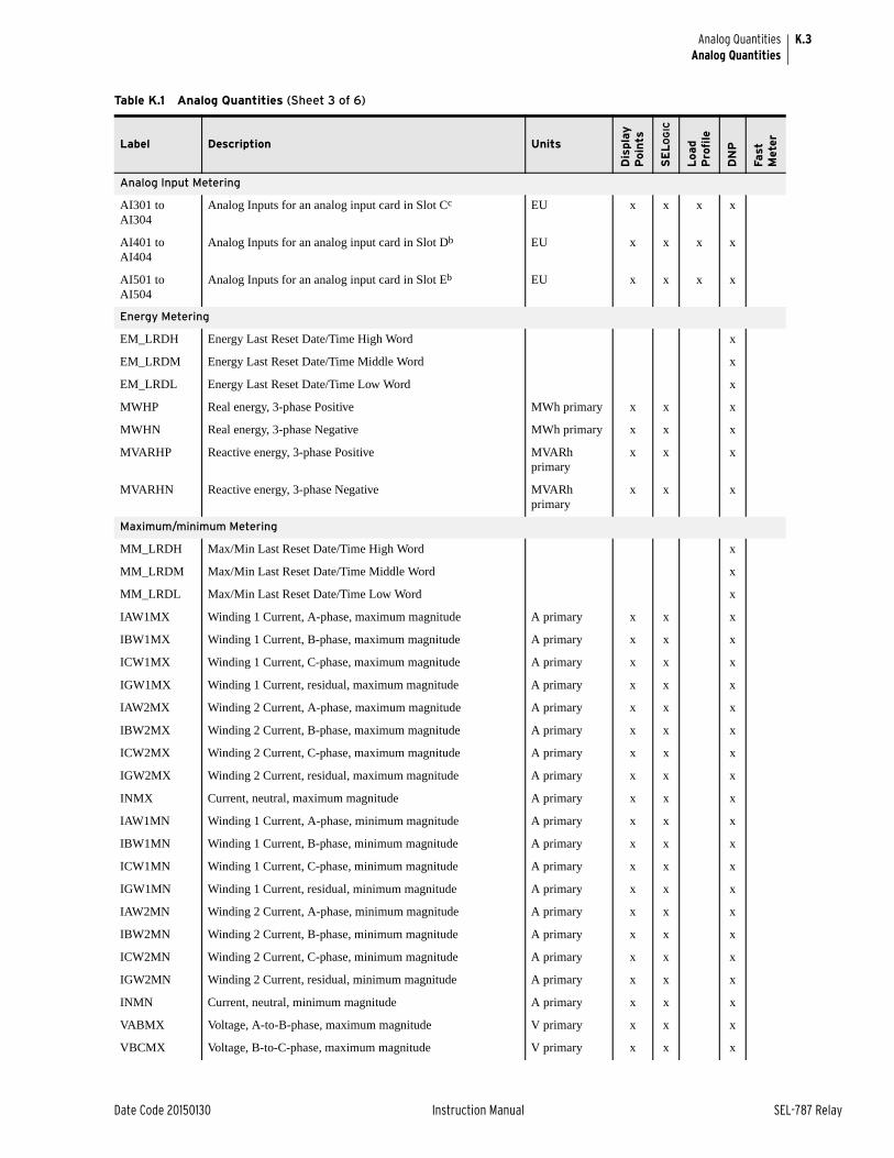
K.3
Date Code 20150130 Instruction Manual SEL-787 Relay
Analog QuantitiesAnalog Quantities
Analog Input Metering
AI301 to AI304
Analog Inputs for an analog input card in Slot Cc EU x x x x
AI401 to AI404
Analog Inputs for an analog input card in Slot Db EU x x x x
AI501 to AI504
Analog Inputs for an analog input card in Slot Eb EU x x x x
Energy Metering
EM_LRDH Energy Last Reset Date/Time High Word x
EM_LRDM Energy Last Reset Date/Time Middle Word x
EM_LRDL Energy Last Reset Date/Time Low Word x
MWHP Real energy, 3-phase Positive MWh primary x x x
MWHN Real energy, 3-phase Negative MWh primary x x x
MVARHP Reactive energy, 3-phase Positive MVARh primary
x x x
MVARHN Reactive energy, 3-phase Negative MVARh primary
x x x
Maximum/minimum Metering
MM_LRDH Max/Min Last Reset Date/Time High Word x
MM_LRDM Max/Min Last Reset Date/Time Middle Word x
MM_LRDL Max/Min Last Reset Date/Time Low Word x
IAW1MX Winding 1 Current, A-phase, maximum magnitude A primary x x x
IBW1MX Winding 1 Current, B-phase, maximum magnitude A primary x x x
ICW1MX Winding 1 Current, C-phase, maximum magnitude A primary x x x
IGW1MX Winding 1 Current, residual, maximum magnitude A primary x x x
IAW2MX Winding 2 Current, A-phase, maximum magnitude A primary x x x
IBW2MX Winding 2 Current, B-phase, maximum magnitude A primary x x x
ICW2MX Winding 2 Current, C-phase, maximum magnitude A primary x x x
IGW2MX Winding 2 Current, residual, maximum magnitude A primary x x x
INMX Current, neutral, maximum magnitude A primary x x x
IAW1MN Winding 1 Current, A-phase, minimum magnitude A primary x x x
IBW1MN Winding 1 Current, B-phase, minimum magnitude A primary x x x
ICW1MN Winding 1 Current, C-phase, minimum magnitude A primary x x x
IGW1MN Winding 1 Current, residual, minimum magnitude A primary x x x
IAW2MN Winding 2 Current, A-phase, minimum magnitude A primary x x x
IBW2MN Winding 2 Current, B-phase, minimum magnitude A primary x x x
ICW2MN Winding 2 Current, C-phase, minimum magnitude A primary x x x
IGW2MN Winding 2 Current, residual, minimum magnitude A primary x x x
INMN Current, neutral, minimum magnitude A primary x x x
VABMX Voltage, A-to-B-phase, maximum magnitude V primary x x x
VBCMX Voltage, B-to-C-phase, maximum magnitude V primary x x x
Table K.1 Analog Quantities (Sheet 3 of 6)
Label Description Units
Dis
pla
y
Poin
ts
SE
LO
GIC
Load
Pro
file
DN
P
Fast
M
eter
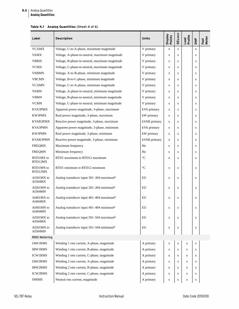
K.4
SEL-787 Relay Instruction Manual Date Code 20150130
Analog QuantitiesAnalog Quantities
VCAMX Voltage, C-to-A-phase, maximum magnitude V primary x x x
VAMX Voltage, A-phase-to-neutral, maximum magnitude V primary x x x
VBMX Voltage, B-phase-to-neutral, maximum magnitude V primary x x x
VCMX Voltage, C-phase-to-neutral, maximum magnitude V primary x x x
VABMN Voltage, A-to-B-phase, minimum magnitude V primary x x x
VBCMN Voltage, B-to-C-phase, minimum magnitude V primary x x x
VCAMN Voltage, C-to-A-phase, minimum magnitude V primary x x x
VAMN Voltage, A-phase-to-neutral, minimum magnitude V primary x x x
VBMN Voltage, B-phase-to-neutral, minimum magnitude V primary x x x
VCMN Voltage, C-phase-to-neutral, minimum magnitude V primary x x x
KVA3PMX Apparent power magnitude, 3-phase, maximum kVA primary x x x
KW3PMX Real power magnitude, 3-phase, maximum kW primary x x x
KVAR3PMX Reactive power magnitude, 3-phase, maximum kVAR primary x x x
KVA3PMN Apparent power magnitude, 3-phase, minimum kVA primary x x x
KW3PMN Real power magnitude, 3-phase, minimum kW primary x x x
KVAR3PMN Reactive power magnitude, 3-phase, minimum kVAR primary x x x
FREQMX Maximum frequency Hz x x x
FREQMN Minimum frequency Hz x x x
RTD1MX to RTD12MX
RTD1 maximum to RTD12 maximum °C x x x
RTD1MN to RTD12MN
RTD1 minimum to RTD12 minimum °C x x x
AI301MX to AI304MX
Analog transducer input 301–304 maximumb EU x x x
AI301MN to AI304MN
Analog transducer input 301–304 minimumb EU x x x
AI401MX to AI404MX
Analog transducer input 401–404 maximumb EU x x x
AI401MN to AI404MN
Analog transducer input 401–404 minimumb EU x x x
AI501MX to AI504MX
Analog transducer input 501–504 maximumb EU x x x
AI501MN to AI504MN
Analog transducer input 501–504 minimumb EU x x x
RMS Metering
IAW1RMS Winding 1 rms current, A-phase, magnitude A primary x x x x
IBW1RMS Winding 1 rms current, B-phase, magnitude A primary x x x x
ICW1RMS Winding 1 rms current, C-phase, magnitude A primary x x x x
IAW2RMS Winding 2 rms current, A-phase, magnitude A primary x x x x
IBW2RMS Winding 2 rms current, B-phase, magnitude A primary x x x x
ICW2RMS Winding 2 rms current, C-phase, magnitude A primary x x x x
INRMS Neutral rms current, magnitude A primary x x x x
Table K.1 Analog Quantities (Sheet 4 of 6)
Label Description Units
Dis
pla
y
Poin
ts
SE
LO
GIC
Load
Pro
file
DN
P
Fast
M
eter
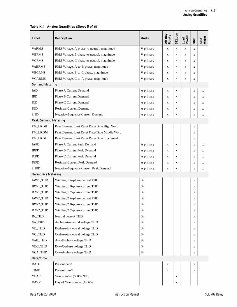
K.5
Date Code 20150130 Instruction Manual SEL-787 Relay
Analog QuantitiesAnalog Quantities
VARMS RMS Voltage, A-phase-to-neutral, magnitude V primary x x x x
VBRMS RMS Voltage, B-phase-to-neutral, magnitude V primary x x x x
VCRMS RMS Voltage, C-phase-to-neutral, magnitude V primary x x x x
VABRMS RMS Voltage, A-to-B-phase, magnitude V primary x x x x
VBCRMS RMS Voltage, B-to-C-phase, magnitude V primary x x x x
VCARMS RMS Voltage, C-to-A-phase, magnitude V primary x x x x
Demand Metering
IAD Phase A Current Demand A primary x x x x
IBD Phase B Current Demand A primary x x x x
ICD Phase C Current Demand A primary x x x x
IGD Residual Current Demand A primary x x x x
3I2D Negative-Sequence Current Demand A primary x x x x
Peak Demand Metering
PM_LRDH Peak Demand Last Reset Date/Time High Word x
PM_LRDM Peak Demand Last Reset Date/Time Middle Word x
PM_LRDL Peak Demand Last Reset Date/Time Low Word x
IAPD Phase A Current Peak Demand A primary x x x x
IBPD Phase B Current Peak Demand A primary x x x x
ICPD Phase C Current Peak Demand A primary x x x x
IGPD Residual Current Peak Demand A primary x x x x
3I2PD Negative-Sequence Current Peak Demand A primary x x x x
Harmonics Metering
IAW1_THD Winding 1 A-phase current THD % x
IBW1_THD Winding 1 B-phase current THD % x
ICW1_THD Winding 1 C-phase current THD % x
IAW2_THD Winding 2 A-phase current THD % x
IBW2_THD Winding 2 B-phase current THD % x
ICW2_THD Winding 2 C-phase current THD % x
IN_THD Neutral current THD % x
VA_THD A-phase-to-neutral voltage THD % x
VB_THD B-phase-to-neutral voltage THD % x
VC_THD C-phase-to-neutral voltage THD % x
VAB_THD A-to-B-phase voltage THD % x
VBC_THD B-to-C-phase voltage THD % x
VCA_THD C-to-A-phase voltage THD % x
Date/Time
DATE Present dated x x
TIME Present timec x x
YEAR Year number (0000-9999) x
DAYY Day of Year number (1-366) x
Table K.1 Analog Quantities (Sheet 5 of 6)
Label Description Units
Dis
pla
y
Poin
ts
SE
LO
GIC
Load
Pro
file
DN
P
Fast
M
eter
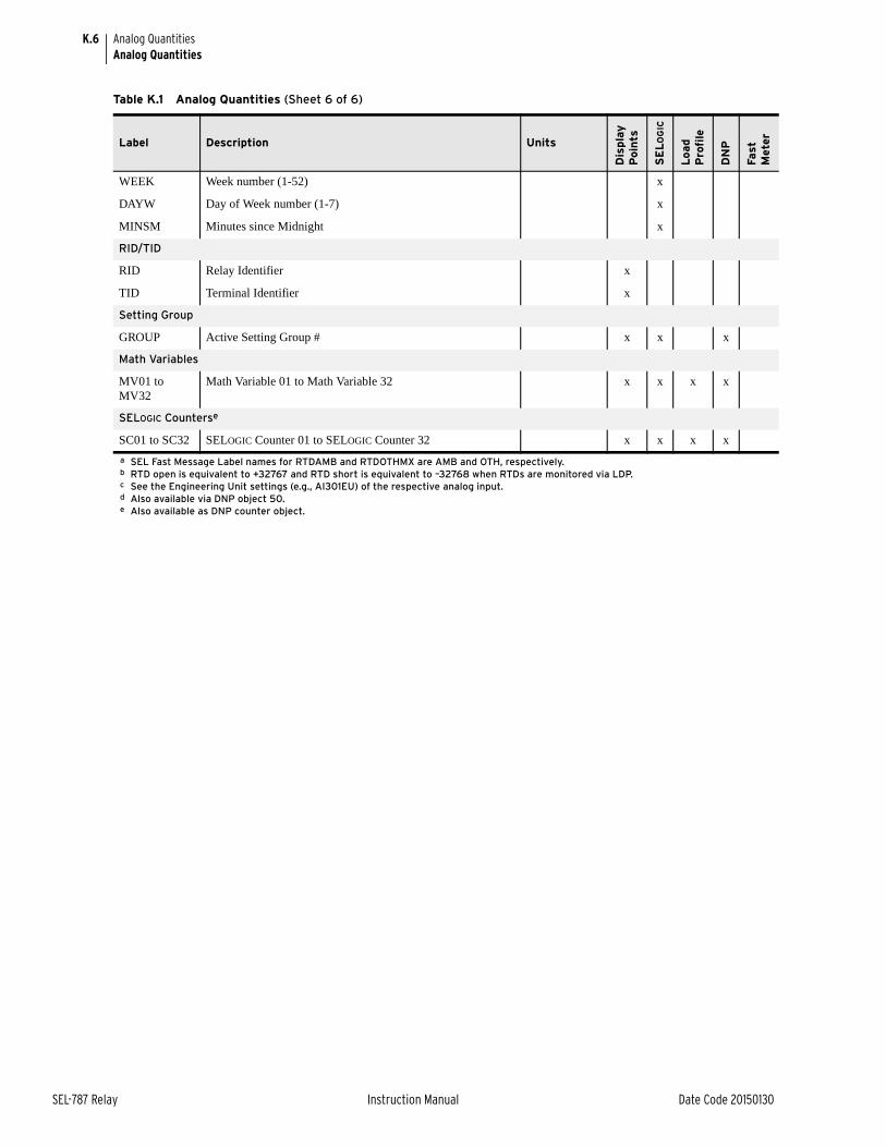
K.6
SEL-787 Relay Instruction Manual Date Code 20150130
Analog QuantitiesAnalog Quantities
WEEK Week number (1-52) x
DAYW Day of Week number (1-7) x
MINSM Minutes since Midnight x
RID/TID
RID Relay Identifier x
TID Terminal Identifier x
Setting Group
GROUP Active Setting Group # x x x
Math Variables
MV01 to MV32
Math Variable 01 to Math Variable 32 x x x x
SELOGIC Counterse
SC01 to SC32 SELOGIC Counter 01 to SELOGIC Counter 32 x x x x
a SEL Fast Message Label names for RTDAMB and RTDOTHMX are AMB and OTH, respectively.b RTD open is equivalent to +32767 and RTD short is equivalent to –32768 when RTDs are monitored via LDP.c See the Engineering Unit settings (e.g., AI301EU) of the respective analog input.d Also available via DNP object 50.e Also available as DNP counter object.
Table K.1 Analog Quantities (Sheet 6 of 6)
Label Description Units
Dis
pla
y
Poin
ts
SE
LO
GIC
Load
Pro
file
DN
P
Fast
M
eter
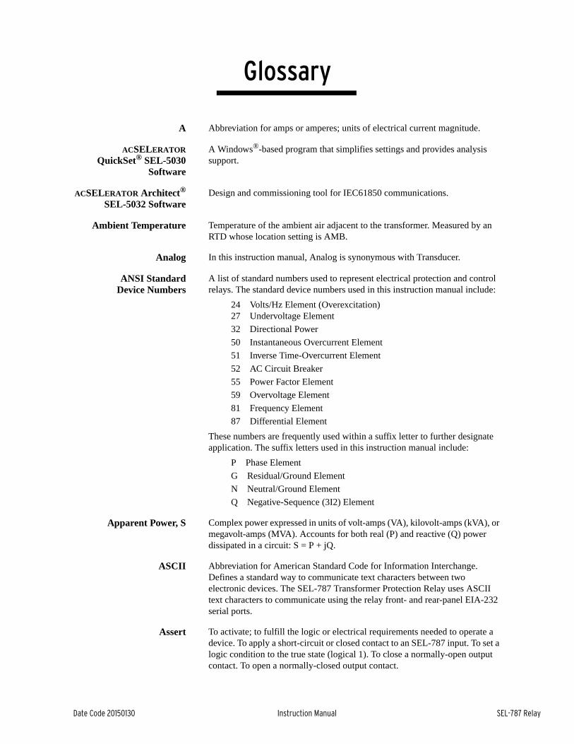
Date Code 20150130 Instruction Manual SEL-787 Relay
GlossaryInstruction Manual
A Abbreviation for amps or amperes; units of electrical current magnitude.
ACSELERATORQuickSet® SEL-5030
Software
A Windows®-based program that simplifies settings and provides analysis support.
ACSELERATOR Architect®
SEL-5032 SoftwareDesign and commissioning tool for IEC61850 communications.
Ambient Temperature Temperature of the ambient air adjacent to the transformer. Measured by an RTD whose location setting is AMB.
Analog In this instruction manual, Analog is synonymous with Transducer.
ANSI StandardDevice Numbers
A list of standard numbers used to represent electrical protection and control relays. The standard device numbers used in this instruction manual include:
24 Volts/Hz Element (Overexcitation)27 Undervoltage Element
32 Directional Power
50 Instantaneous Overcurrent Element
51 Inverse Time-Overcurrent Element
52 AC Circuit Breaker
55 Power Factor Element
59 Overvoltage Element
81 Frequency Element
87 Differential Element
These numbers are frequently used within a suffix letter to further designate application. The suffix letters used in this instruction manual include:
P Phase Element
G Residual/Ground Element
N Neutral/Ground Element
Q Negative-Sequence (3I2) Element
Apparent Power, S Complex power expressed in units of volt-amps (VA), kilovolt-amps (kVA), or megavolt-amps (MVA). Accounts for both real (P) and reactive (Q) power dissipated in a circuit: S = P + jQ.
ASCII Abbreviation for American Standard Code for Information Interchange. Defines a standard way to communicate text characters between two electronic devices. The SEL-787 Transformer Protection Relay uses ASCII text characters to communicate using the relay front- and rear-panel EIA-232 serial ports.
Assert To activate; to fulfill the logic or electrical requirements needed to operate a device. To apply a short-circuit or closed contact to an SEL-787 input. To set a logic condition to the true state (logical 1). To close a normally-open output contact. To open a normally-closed output contact.
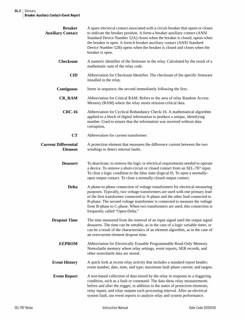
GL.2 GlossaryBreaker Auxiliary Contact–Event Report
SEL-787 Relay Instruction Manual Date Code 20150130
BreakerAuxiliary Contact
A spare electrical contact associated with a circuit breaker that opens or closes to indicate the breaker position. A form-a breaker auxiliary contact (ANSI Standard Device Number 52A) closes when the breaker is closed, opens when the breaker is open. A form-b breaker auxiliary contact (ANSI Standard Device Number 52B) opens when the breaker is closed and closes when the breaker is open.
Checksum A numeric identifier of the firmware in the relay. Calculated by the result of a mathematic sum of the relay code.
CID Abbreviation for Checksum Identifier. The checksum of the specific firmware installed in the relay.
Contiguous Items in sequence; the second immediately following the first.
CR_RAM Abbreviation for Critical RAM. Refers to the area of relay Random Access Memory (RAM) where the relay stores mission-critical data.
CRC-16 Abbreviation for Cyclical Redundancy Check-16. A mathematical algorithm applied to a block of digital information to produce a unique, identifying number. Used to ensure that the information was received without data corruption.
CT Abbreviation for current transformer.
Current DifferentialElement
A protection element that measures the difference current between the two windings to detect internal faults.
Deassert To deactivate; to remove the logic or electrical requirements needed to operate a device. To remove a short-circuit or closed contact from an SEL-787 input. To clear a logic condition to the false state (logical 0). To open a normally-open output contact. To close a normally-closed output contact.
Delta A phase-to-phase connection of voltage transformers for electrical measuring purposes. Typically, two voltage transformers are used with one primary lead of the first transformer connected to A-phase and the other lead connected to B-phase. The second voltage transformer is connected to measure the voltage from B-phase to C-phase. When two transformers are used, this connection is frequently called “Open-Delta.”
Dropout Time The time measured from the removal of an input signal until the output signal deasserts. The time can be settable, as in the case of a logic variable timer, or can be a result of the characteristics of an element algorithm, as in the case of an overcurrent element dropout time.
EEPROM Abbreviation for Electrically Erasable Programmable Read-Only Memory. Nonvolatile memory where relay settings, event reports, SER records, and other nonvolatile data are stored.
Event History A quick look at recent relay activity that includes a standard report header; event number, date, time, and type; maximum fault phase current; and targets.
Event Report A text-based collection of data stored by the relay in response to a triggering condition, such as a fault or command. The data show relay measurements before and after the trigger, in addition to the states of protection elements, relay inputs, and relay outputs each processing interval. After an electrical system fault, use event reports to analyze relay and system performance.
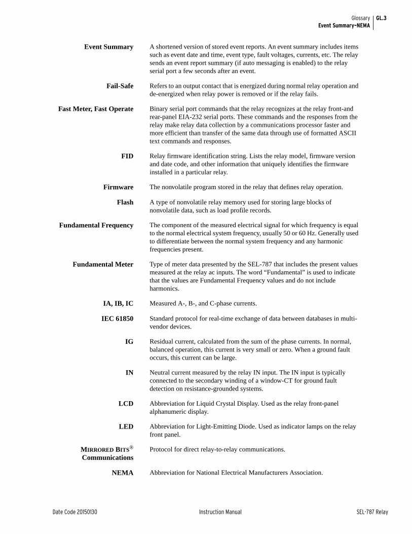
GL.3GlossaryEvent Summary–NEMA
Date Code 20150130 Instruction Manual SEL-787 Relay
Event Summary A shortened version of stored event reports. An event summary includes items such as event date and time, event type, fault voltages, currents, etc. The relay sends an event report summary (if auto messaging is enabled) to the relay serial port a few seconds after an event.
Fail-Safe Refers to an output contact that is energized during normal relay operation and de-energized when relay power is removed or if the relay fails.
Fast Meter, Fast Operate Binary serial port commands that the relay recognizes at the relay front-and rear-panel EIA-232 serial ports. These commands and the responses from the relay make relay data collection by a communications processor faster and more efficient than transfer of the same data through use of formatted ASCII text commands and responses.
FID Relay firmware identification string. Lists the relay model, firmware version and date code, and other information that uniquely identifies the firmware installed in a particular relay.
Firmware The nonvolatile program stored in the relay that defines relay operation.
Flash A type of nonvolatile relay memory used for storing large blocks of nonvolatile data, such as load profile records.
Fundamental Frequency The component of the measured electrical signal for which frequency is equal to the normal electrical system frequency, usually 50 or 60 Hz. Generally used to differentiate between the normal system frequency and any harmonic frequencies present.
Fundamental Meter Type of meter data presented by the SEL-787 that includes the present values measured at the relay ac inputs. The word “Fundamental” is used to indicate that the values are Fundamental Frequency values and do not include harmonics.
IA, IB, IC Measured A-, B-, and C-phase currents.
IEC 61850 Standard protocol for real-time exchange of data between databases in multi-vendor devices.
IG Residual current, calculated from the sum of the phase currents. In normal, balanced operation, this current is very small or zero. When a ground fault occurs, this current can be large.
IN Neutral current measured by the relay IN input. The IN input is typically connected to the secondary winding of a window-CT for ground fault detection on resistance-grounded systems.
LCD Abbreviation for Liquid Crystal Display. Used as the relay front-panel alphanumeric display.
LED Abbreviation for Light-Emitting Diode. Used as indicator lamps on the relay front panel.
MIRRORED BITS®
CommunicationsProtocol for direct relay-to-relay communications.
NEMA Abbreviation for National Electrical Manufacturers Association.

GL.4 GlossaryNeutral Overcurrent Element–Relay Word Bit
SEL-787 Relay Instruction Manual Date Code 20150130
NeutralOvercurrent Element
A protection element that causes the relay to trip when the neutral current magnitude (measured by the IN input) exceeds a user settable value. Used to detect and trip in response to ground faults.
Nominal Frequency Normal electrical system frequency, usually 50 or 60 Hz.
Nonfail-Safe Refers to an output contact that is not energized during normal relay operation. When referred to a trip output contact, the protected equipment remains in operation unprotected when relay power is removed or if the relay fails.
Nonvolatile Memory Relay memory that is able to correctly maintain data it is storing even when the relay is de-energized.
Overfrequency Element A protection element that causes the relay to trip when the measured electrical system frequency exceeds a settable frequency.
Phase Rotation The sequence of voltage or current phasors in a multi-phase electrical system. In an ABC phase rotation system, the B-phase voltage lags the A-phase voltage by 120 degrees, and the C-phase voltage lags B-phase voltage by 120 degrees. In an ACB phase rotation system, the C-phase voltage lags the A-phase voltage by 120°, and the B-phase voltage lags the C-phase voltage by 120 degrees.
Pickup Time The time measured from the application of an input signal until the output signal asserts. The time can be settable, as in the case of a logic variable timer, or can be a result of the characteristics of an element algorithm, as in the case of an overcurrent element pickup time.
Pinout The definition or assignment of each electrical connection at an interface. Typically refers to a cable, connector, or jumper.
Power, P Real part of the complex power (S) expressed in units of Watts (W), kilovolt-watts (kW), or megawatts (MW).
Power Factor The cosine of the angle by which phase current lags phase voltage in an ac electrical circuit. Power factor equals 1.0 for power flowing to a resistive load.
Power, Q Reactive part of the complex power (S) expressed in units of Vars (W), kilovars (kVar), or megavars (MVar).
PT Abbreviation for potential transformer. Also referred to as a voltage transformer or VT.
RAM Abbreviation for Random Access Memory. Volatile memory where the relay stores intermediate calculation results, Relay Word bits, and other data that are updated every processing interval.
Relay Word The collection of relay element and logic results. Each element or result is represented by a unique identifier, known as a Relay Word bit.
Relay Word Bit A single relay element or logic result that the relay updates once each processing interval. A Relay Word bit can be equal to either logical 1 or logical 0. Logical 1 represents a true logic condition, picked up element, or asserted contact input or contact output. Logical 0 represents a false logic condition, dropped out element, or deasserted contact input or contact output. You can use Relay Word bits in SELOGIC control equations to control relay tripping, event triggering, and output contacts, as well as other functions.
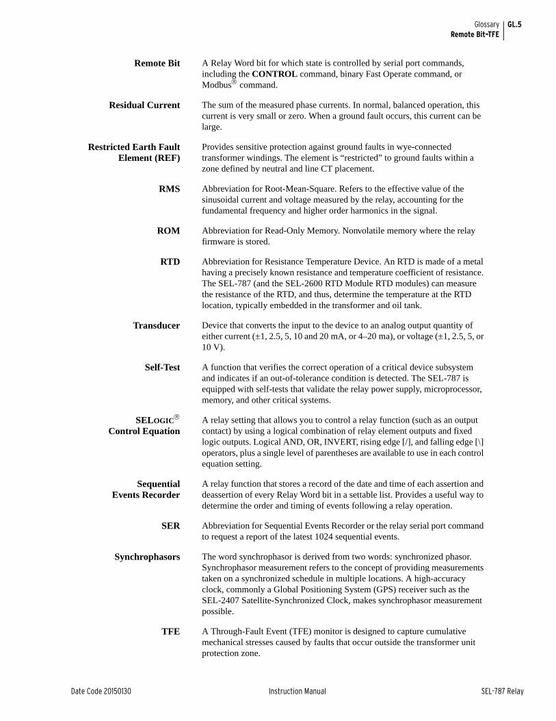
GL.5GlossaryRemote Bit–TFE
Date Code 20150130 Instruction Manual SEL-787 Relay
Remote Bit A Relay Word bit for which state is controlled by serial port commands, including the CONTROL command, binary Fast Operate command, or Modbus command.
Residual Current The sum of the measured phase currents. In normal, balanced operation, this current is very small or zero. When a ground fault occurs, this current can be large.
Restricted Earth FaultElement (REF)
Provides sensitive protection against ground faults in wye-connected transformer windings. The element is “restricted” to ground faults within a zone defined by neutral and line CT placement.
RMS Abbreviation for Root-Mean-Square. Refers to the effective value of the sinusoidal current and voltage measured by the relay, accounting for the fundamental frequency and higher order harmonics in the signal.
ROM Abbreviation for Read-Only Memory. Nonvolatile memory where the relay firmware is stored.
RTD Abbreviation for Resistance Temperature Device. An RTD is made of a metal having a precisely known resistance and temperature coefficient of resistance. The SEL-787 (and the SEL-2600 RTD Module RTD modules) can measure the resistance of the RTD, and thus, determine the temperature at the RTD location, typically embedded in the transformer and oil tank.
Transducer Device that converts the input to the device to an analog output quantity of either current (±1, 2.5, 5, 10 and 20 mA, or 4–20 ma), or voltage (±1, 2.5, 5, or 10 V).
Self-Test A function that verifies the correct operation of a critical device subsystem and indicates if an out-of-tolerance condition is detected. The SEL-787 is equipped with self-tests that validate the relay power supply, microprocessor, memory, and other critical systems.
SELOGIC
Control EquationA relay setting that allows you to control a relay function (such as an output contact) by using a logical combination of relay element outputs and fixed logic outputs. Logical AND, OR, INVERT, rising edge [/], and falling edge [\] operators, plus a single level of parentheses are available to use in each control equation setting.
SequentialEvents Recorder
A relay function that stores a record of the date and time of each assertion and deassertion of every Relay Word bit in a settable list. Provides a useful way to determine the order and timing of events following a relay operation.
SER Abbreviation for Sequential Events Recorder or the relay serial port command to request a report of the latest 1024 sequential events.
Synchrophasors The word synchrophasor is derived from two words: synchronized phasor. Synchrophasor measurement refers to the concept of providing measurements taken on a synchronized schedule in multiple locations. A high-accuracy clock, commonly a Global Positioning System (GPS) receiver such as the SEL-2407 Satellite-Synchronized Clock, makes synchrophasor measurement possible.
TFE A Through-Fault Event (TFE) monitor is designed to capture cumulative mechanical stresses caused by faults that occur outside the transformer unit protection zone.
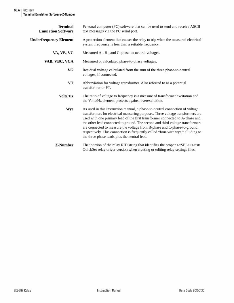
GL.6 GlossaryTerminal Emulation Software–Z-Number
SEL-787 Relay Instruction Manual Date Code 20150130
TerminalEmulation Software
Personal computer (PC) software that can be used to send and receive ASCII text messages via the PC serial port.
Underfrequency Element A protection element that causes the relay to trip when the measured electrical system frequency is less than a settable frequency.
VA, VB, VC Measured A-, B-, and C-phase-to-neutral voltages.
VAB, VBC, VCA Measured or calculated phase-to-phase voltages.
VG Residual voltage calculated from the sum of the three phase-to-neutral voltages, if connected.
VT Abbreviation for voltage transformer. Also referred to as a potential transformer or PT.
Volts/Hz The ratio of voltage to frequency is a measure of transformer excitation and the Volts/Hz element protects against overexcitation.
Wye As used in this instruction manual, a phase-to-neutral connection of voltage transformers for electrical measuring purposes. Three voltage transformers are used with one primary lead of the first transformer connected to A-phase and the other lead connected to ground. The second and third voltage transformers are connected to measure the voltage from B-phase and C-phase-to-ground, respectively. This connection is frequently called “four-wire wye,” alluding to the three phase leads plus the neutral lead.
Z-Number That portion of the relay RID string that identifies the proper ACSELERATOR QuickSet relay driver version when creating or editing relay settings files.
Date Code 20150130 Instruction Manual SEL-787 Relay
IndexInstruction Manual
Page numbers appearing in bold mark the location of the topic’s primary discussion.
Symbols*, Largest Current 9.8
>, Trigger Row 9.8
AAccess Levels 7.18
communications ports 7.15front panel 8.3
Accuracymetering 1.13SNTP time synchronization
accuracy 7.14
AlarmLevel 2 access 2.16
Analog Inputs 4.86adaptive name 4.86name (instrument tag) 4.88sampling frequency 4.86
Analog Outputs 4.90adaptive name 4.90
Apparent Power 5.4See also Meter
ASCII CommandsSee Commands
ASCII ProtocolSee SEL ASCII Protocol
Automatic Messages 7.15See also SEL Binary Protocolsevents 9.1, 9.3front panel 8.3
BBase Unit
communications ports 2.4
Battery, Clock 2.31
Breaker Failure Logic 4.85
CCard Reconfiguration 2.2
Card Terminal Numbers 2.171 ACI card 2.61 ACI/3 AVI card 2.610 RTD card 2.83 DI/4 DO/1 AO card 2.84 AI/4 AO card 2.74 DI/3 DO card 2.104 DI/4 DO card 2.96 ACI card 2.68 DI card 2.9
CEVENT Command 9.2
CHISTORY Command 9.2
Circuit Breaker Auxiliary Contactcontact input 4.69
Close LogicSee Trip/Close Logic 4.67
Commands2ACCESS 7.18ACCESS 7.18ANALOG 7.19CLOSE 7.21COMMUNICATIONS 7.22CONTROL 7.22COPY 7.23COUNTER 7.23DATE 1.7ETHERNET 7.24EVENT 7.24FILE 7.25GOOSE 7.25GROUP 7.27HELP 7.28HISTORY 7.28, 9.6IDENTIFICATION 7.28L_D 7.30LDP 7.29LOOPBACK 7.30MAC 7.31MET 7.31OPEN 7.32PASSWORD 7.33PING 7.34PULSE 7.34QUIT 7.35R_S 7.35SER 7.35SER D 7.36SET 7.36SHOW 7.37STATUS 7.40SUMMARY 7.41TARGET 7.42TFE (through-fault events) 7.42TIME 7.43TRIGGER 7.43, 9.3
Commissioning Tests 10.3–10.7connection test 10.6required equipment 10.3
Communicationsaccess levels 7.15, 7.18ASCII commands 7.17–7.43ASCII protocol 7.2automatic messages 7.15communications ports 7.1connector pinout 7.7control characters 7.15DeviceNet
protocol 7.11, G.1–G.3DNP3 Protocol D.1–D.22
EIA-232 ports 7.1EIA-485 ports 4.96, 7.1establishing communications
procedure 1.5, 7.2Ethernet 7.1, 7.3exception responses E.3factory default settings 1.6, 7.2fiber-optic port 7.1front panel 4.94hardware flow control 7.2IEC 61850 F.1MIRRORED BITS I.1–I.6Modbus protocol E.1port power, rear 7.7rear panel 4.96SEL ASCII protocol 7.14, C.1SEL protocols 7.10, C.1set relay 6.4SNTP protocol 7.12Synchrophasors (C37.118
protocol) H.1–H.13
Communications Cables and Connections 7.8DeviceNet G.2EIA-232 1.5, 7.8EIA-485 7.7PC-to-relay cable pinout 7.8
Communications PortsSee Communications
Compressed ASCII 9.2, C.1
Configurable Label Kit 1.3, 8.13
ConfigurationAI/AO card 2.13part number 2.13, 3.7
Connectionsrear panel 2.17
Contact Outputs 2.22, 4.80control equations 4.80de-energized position 2.22factory defaults 4.80fail-safe
operation 2.22settings 4.80
nonfail-safe operation 2.22output 4.77
Contactor/Circuit Breaker Auxiliary Contactcontrol equation 52A 4.69
Core-Balance CTplacement 2.25
CSUMMARY Command 9.2
Current Differential ElementsSee Differential Elements
IN.2 IndexD–I
SEL-787 Relay Instruction Manual Date Code 20150130
Currentsaverage current 5.3connections
ground/neutral 2.25phase 2.25
See also Core-Balance CT; Meter
DDNP3 Protocol D.1–D.22
analog inputs D.20binary inputs D.20data map D.18DNP Map Settings 4.110DNP3 LAN/WAN D.5DNP3 levels D.1DNP3 serial D.3DNP3 Settings D.10event data D.8object list D.13
Debounceac mode 4.91dc mode 4.91digital inputs 4.73
DeviceNet G.1–G.3See also Communications
Differential Elements 4.5–4.30harmonic blocking 4.10harmonic restraint 4.9operate quantities 4.5TAP calculations 4.24
Dimensionsmechanical 2.2panel cut 2.2
Displayfront panel 8.2HMI (SEL-5030) 3.12LCD 4.97
Display Points 4.98name, alias, set string, and clear
string 4.99–4.104rotating display 4.105
EEarthing
See Grounding
Ethernet Port(s) 2.5, 7.3settings 4.95
Event 9.2data capture time 4.110ER control equation 4.110, 9.2length 4.110nonvolatile 9.1TR initiate 9.2trigger 9.3
Event History 9.5HIS command 7.28, 9.6retrieving history 9.6
application example 9.6See also Event
Event Report 9.2*, largest current 9.8See also Event>, trigger row 9.8analog event report 9.7clearing the buffer 9.6column definitions 9.7–9.8differential event report 9.19digital event report 9.15EVE command 7.24filtered 9.7phasor calculation 9.13retrieving event data 9.6
application example 9.8–9.13summary section 9.3–9.5trigger 9.3trigger settings 4.110unfiltered 9.7
Event Summary 9.3–9.5See also Eventcontents 9.3event type 9.4SUMMARY command 7.41
FFactory Default
default settings 4.2–4.111EIA-232 serial ports 7.2LEDs 8.12passwords 7.33tripping logic 4.68
Fail-Safe 2.22, 4.81TRIP output 4.81See also Contact Outputs
Fast Binary Messages C.2See also Fast Operate; Fast Meter;
Fast SER
Fast Meter C.2See also SEL Binary Protocols
Fast OperateSee also SEL Binary Protocols
Fast SER C.2
Firmwareupgrade instructions B.1–B.8versions A.1
Frequencyevent report 9.3event summary 7.41meter 5.4tracking 1.10See also Meter
Frequency Elements 4.60logic diagram 4.60overfrequency 4.60underfrequency 4.60
Front Panel 8.1–8.14access levels 8.3, 8.4automatic messages 8.3communications port 4.94
configurable labels 1.4, 8.13contrast 8.2display contrast 8.2ENABLED LED 8.13menus 8.4Meter menu 5.3password entry 8.3pushbuttons 8.2, 8.5reset trip/targets 8.13serial port 4.94set relay 6.2target LEDs 8.12timeout 8.4
Front-Panel Set (SET F Command) 4.97–4.107
Functional Overview 1.1
Functional Tests 10.7–10.10currents 10.7power and power factor 10.8test connections 10.7, 10.8voltages, delta 10.9
Fundamental Meter 5.3
Fuserating 2.31replacement 2.31
GGlobal Settings (SET G
Command) 4.81–4.93
Grounding 2.19, 2.21
HHistory
See Event History
II/O Configuration 2.2, 2.13
IEC 61850 F.1ACSI Conformance
Statements F.35Configuration F.11GOOSE F.4GOOSE Processing F.10Introduction to F.2Logical Nodes F.15Manufacturing Messaging
Specification (MMS) F.4, F.29Operation F.3Protocol Implementation
Conformance Statement F.29Substation Configuration Language
(SCL) F.5
Installation 2.1–2.31dimensions 2.2panel mounting 2.2physical location 2.1power supply 1.4, 2.19rack mounting accessory 1.3See also Commissioning Tests
IN.3IndexJ–S
Date Code 20150130 Instruction Manual SEL-787 Relay
Instantaneous Overcurrent ElementsSee Overcurrent Elements
Instruction Manual Versions A.10
IRIG-B Time Synchronization 7.5, 7.29input specifications 1.10IRI command 7.29via communications processor C.3
JJumpers 2.13
analog card (V or I) 2.13analog card configuration 2.13breaker control jumper 2.15Password 2.15SELBOOT JUMPER 2.15
LLabels
configurable 1.4, 8.13
Latch Bits 4.71nonvolatile state 4.72
LCDSee Front Panel
LED Settings 4.106Pushbutton LEDs 4.107Target LEDs 4.106
Load Profiling 5.12
Local Bits 4.105NLB, CLB, SLB, PLB 4.105
Logic Settingsoutput contacts 4.80
Loss of Potential (LOP) 4.60
Low-Level Test Interface 10.2
MMaintenance 10.10
routine checks 10.10self testing 10.11
MenusSee Front Panel, menus
Meter 5.3accuracy 1.13analog input 5.9current 5.2, 5.3, 5.4demand 5.9differential 5.4energy 5.6frequency 5.4fundamental 5.3harmonic 5.10math variable 5.8minimum/maximum 5.6negative sequence 5.4peak demand 5.9power factor 5.2reactive power 5.2, 5.3real power 5.2rms 5.8RTD 5.5RTD temperatures 5.5
synchrophasor 5.11, H.10temperature 5.5thermal 5.5voltage 5.3, 5.4
METER PM CommandPhasor Measurement and Control
Unit H.10
MIRRORED BITS I.1–I.6
Modbus E.103h read holding registers E.804h input holding registers E.806h preset single register E.1208h loopback diagnostic
command E.1310h preset multiple registers E.1360h read parameter E.1461h read parameter text E.1662h read enumeration text E.167Dh encapsulated packet E.177Eh NOP (no operation) E.18contact outputs E.18cyclical redundancy check E.3exception responses E.3function codes E.2history data E.23Modbus Map Settings 4.111Modbus Register Map E.23password protection E.18protocol description E.1protocol setting 4.96query E.2relay settings E.18response E.2settings 4.96
NNetwork Parameters 3.3
Nonisolated EIA-232 Serial Port 2.5
OOvercurrent Elements 4.34
adaptive overcurrent element 4.35logic diagram 4.36negative-sequence 4.37, 4.41neutral 4.41, 4.42residual 4.37, 4.40
Overvoltage Elements 4.49logic diagram 4.50, 4.51
PPassword
access level 7.18–7.19change 7.33factory default 7.33front panel 8.3jumper 2.15
Phase Overcurrent ElementsSee Overcurrent Elements
Phase Rotation 4.81phasor diagram 4.82setting, PHROT 4.81
Port Settings (SET P Command) 4.94
Powerfunctional test 10.8meter 5.4power measurement
convention 5.2
Power Factorfunctional test 10.8meter 5.4power factor measurement
convention 5.2
Power Supplyfuse ratings 2.31
Pushbuttons 8.1–8.4, 8.13navigation 8.4target reset 8.13, 8.14
RRack Mounting Accessory 1.3
Reactivepower measurement
convention 5.2
Reactive Power 5.2meter 5.4
Real Power 5.2meter 5.3See also Meter
Rear Panel 2.18
Rear-Panel Connections 2.17
Relay Word Bits J.1row list J.4
Remote Trip 4.67control input 4.69
Replacement Rear Connector Kit 1.3
Report Settings 4.108Event report 4.110SER trigger 4.109
Resettargets 8.13
Resistance Temperature Device (RTD)alarm temperatures 4.47failure messages 5.5location settings 4.47status messages 5.5temperature vs. resistance 4.47trip temperatures 4.47See also Meter
Restricted Earth Fault (REF) Element 4.30
Retrieveevent 3.10
Rotating Display 4.105
RTDSee Resistance Temperature Device
SSafety Information
Laser/LED Emitter xxiii
SEL ASCII Protocol 7.14, C.1
IN.4 IndexT–Z
SEL-787 Relay Instruction Manual Date Code 20150130
SEL Binary Protocol C.2
SEL Communications Processor C.3–C.10
SEL-2600 Series RTD Module 1.2failure messages 5.5fiber-optic connection 2.21RTD-based protection 4.46
SEL-3306See Synchrophasors
SEL-787 Relaycleaning chassis xxivfeatures 1.1options 1.2
SELBOOT 2.15
Self Tests 10.11
SELOGIC Control Equations 4.73circuit breaker auxiliary 4.69contact output 4.80counters 4.78event trigger 9.2operators 4.73–4.76PMU trigger H.8Relay Word bits J.1timers 4.77trip logic 4.67
Sequential Events Recorder (SER) 7.35, 9.22clearing 9.23example report 9.23retrieving reports 9.23trigger settings 4.109, 9.22
SER (Sequential Events Recorder)automatic deletion and
reinsertion 4.108
SER D Command 7.36
SER, See Sequential Events Recorder (SER)
SET Command 7.36
Set Relayediting keystrokes 6.5serial communications
port 6.4–6.5settings sheets SET.1using front panel 6.2
Setting 6.1calculation method 4.2classes 6.1error messages 6.6front panel 6.2instances 6.1serial communications
port 6.4–6.5settings sheets SET.1
Settings 4.2–4.111analog input example 4.87DNP Map Settings (SET DNP
Command) 4.110Front-Panel Set (SET F
Command) 4.97–4.107Global Settings (SET G
Command) 4.81–4.93Group Settings (SET
Command) 4.2–4.91Logic Settings (SET L
Command) 4.70Modbus Map Settings (SET M
Command) 4.111Port Settings (SET P
Command) 4.94Report Settings (SET R
Command) 4.108
Short Circuit ProtectionSee Overcurrent Elements
Side Panel 2.18
Simple Network Time Protocol (SNTP) 7.12
Software (ACSELERATOR QuickSet) 3.1databases 3.5device editor 3.8expression builder 3.9Human Machine Interface
(HMI) 3.12settings editor 3.6
Specifications 1.9–1.13
Status, Relay 7.40–7.41serial communication port 1.6
DeviceNet status 1.6
SynchrophasorsMET PM Command H.10protocols
C37.118 H.11Relay Word bits H.9settings H.4
TTargets 8.12
front-panel function 8.12reset targets 8.13view using communications
port 7.42
TemperatureSee Resistance Temperature Device
(RTD)
Testing 10.1–10.15acceptance testing 10.3commissioning testing 10.3–10.7connection tests 10.6low-level test interface 10.2
maintenance testing 10.10methods 10.3, 10.10relay elements 10.10self tests 10.11test connections 10.7, 10.8with SER 10.10with targets, LEDs 10.10with terminal 10.10
Through-Fault Event Monitor 5.13
Time CodeSee IRIG-B Time Synchronization
Transformer Protectionapplications 1.4protection elements 4.1
TriggerPMU H.8
Trip ContactSee also Contact Outputsfail-safe operation 2.22, 4.81wiring diagram 2.22
Trip Resetfront-panel function 8.13
Trip/Close Logic 4.67breaker status 52A 4.69logic diagram 4.68trip equation TR 4.67trip Relay Word bit 4.68trip unlatch ULTRIP 4.69
Troubleshooting 10.15setting error messages 6.6
Typographic Conventions xxi
UUndervoltage Elements 4.48
logic diagram 4.49
UpgradeSee Firmware, upgrade instructions
VVoltages
connections 2.23delta wiring diagram 2.24four-wire wye wiring diagram 2.24input settings
example 4.4loss of potential 4.60open-delta wiring diagram 2.24phase-to-neutral voltage
elements 4.49phase-to-phase voltage
elements 4.49See also Meter
ZZ-number 3.7, A.1
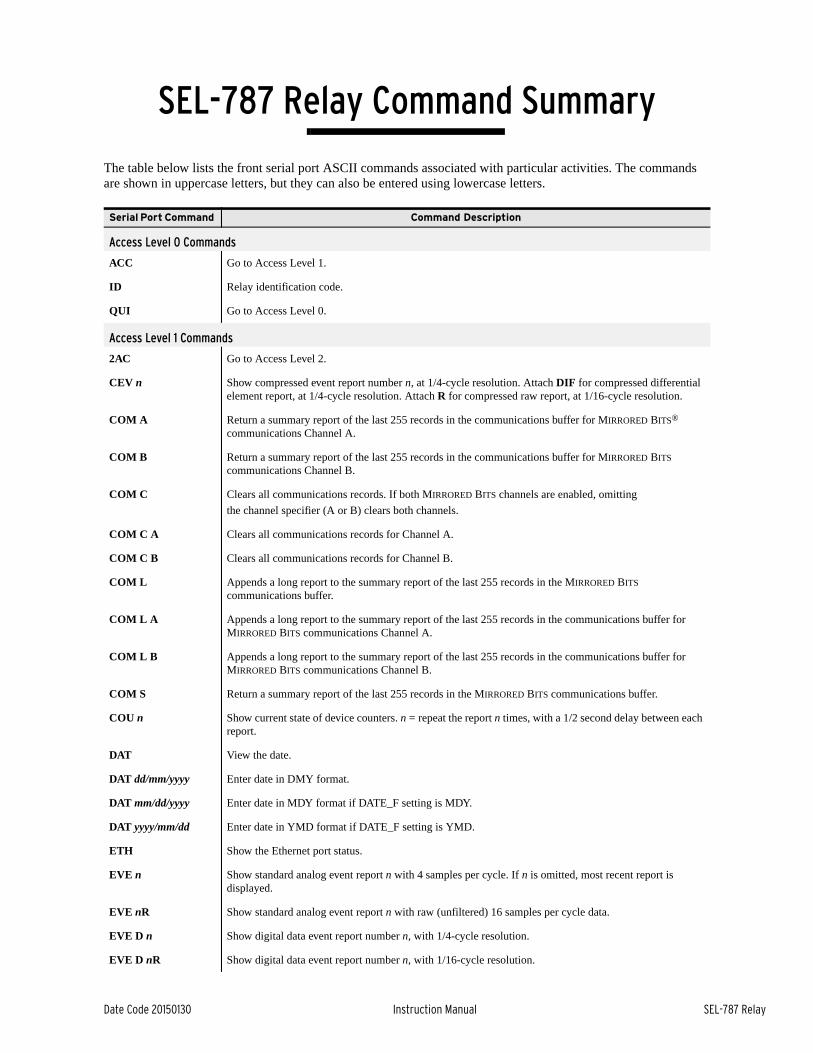
Date Code 20150130 Instruction Manual SEL-787 Relay
SEL-787 Relay Command Summary
The table below lists the front serial port ASCII commands associated with particular activities. The commands are shown in uppercase letters, but they can also be entered using lowercase letters.
Serial Port Command Command Description
Access Level 0 Commands
ACC Go to Access Level 1.
ID Relay identification code.
QUI Go to Access Level 0.
Access Level 1 Commands
2AC Go to Access Level 2.
CEV n Show compressed event report number n, at 1/4-cycle resolution. Attach DIF for compressed differential element report, at 1/4-cycle resolution. Attach R for compressed raw report, at 1/16-cycle resolution.
COM A Return a summary report of the last 255 records in the communications buffer for MIRRORED BITS® communications Channel A.
COM B Return a summary report of the last 255 records in the communications buffer for MIRRORED BITS communications Channel B.
COM C Clears all communications records. If both MIRRORED BITS channels are enabled, omitting
the channel specifier (A or B) clears both channels.
COM C A Clears all communications records for Channel A.
COM C B Clears all communications records for Channel B.
COM L Appends a long report to the summary report of the last 255 records in the MIRRORED BITS communications buffer.
COM L A Appends a long report to the summary report of the last 255 records in the communications buffer for MIRRORED BITS communications Channel A.
COM L B Appends a long report to the summary report of the last 255 records in the communications buffer for MIRRORED BITS communications Channel B.
COM S Return a summary report of the last 255 records in the MIRRORED BITS communications buffer.
COU n Show current state of device counters. n = repeat the report n times, with a 1/2 second delay between each report.
DAT View the date.
DAT dd/mm/yyyy Enter date in DMY format.
DAT mm/dd/yyyy Enter date in MDY format if DATE_F setting is MDY.
DAT yyyy/mm/dd Enter date in YMD format if DATE_F setting is YMD.
ETH Show the Ethernet port status.
EVE n Show standard analog event report n with 4 samples per cycle. If n is omitted, most recent report is displayed.
EVE nR Show standard analog event report n with raw (unfiltered) 16 samples per cycle data.
EVE D n Show digital data event report number n, with 1/4-cycle resolution.
EVE D nR Show digital data event report number n, with 1/16-cycle resolution.

2 SEL-787 Relay Command Summary
SEL-787 Relay Instruction Manual Date Code 20150130
EVE DIF1 n Show differential element 1 event report number n, with 1/4-cycle resolution.
EVE DIF2 n Show differential element 2 event report number n, with 1/4-cycle resolution.
EVE DIF3 n Show differential element 3 event report number n, with 1/4-cycle resolution.
EVE R n Show raw analog data event report number n, with 1/16-cycle resolution, same as EVE n R.
FIL DIR Return a list of files.
FIL READ filename Transfer settings file filename from the relay to the PC.
FIL SHOW filename Filename 1 displays contents of the file filename.
GOO k Display transmit and receive GOOSE messaging information. Enter number k to scroll the GOOSE data k times on the screen.
GRO Display active group setting.
HEL Display a short description of selected commands.
HIS n Show summary of n latest event reports, where n = 1 is the most recent entry. If n is not specified, all event report summaries are displayed.
HIS C or R Clear or reset history buffer.
IRIG Force synchronization of internal control clock to IRIG-B time-code input.
LDP Display signal profile data.
LDP C Clear signal profile data.
MAC Display the MAC address of the Ethernet® port (PORT 1).
MET Display fundamental metering data. (Can also use MET F.)
MET k Display fundamental metering data k times, where k is between 1 and 32767.
MET AI Display analog input (transducer) data.
MET DEM k Display demand metering data, in primary amperes. Enter number k to scroll metering k times on screen.
MET DIF k Display differential metering data. Enter number k to scroll metering k times on screen.
MET E Display energy metering data.
MET H Generate harmonic report for all input currents and voltages, showing first- to fifth-harmonic levels and %THD (total harmonic distortion).
MET M Display minimum and maximum metering data.
MET MV Display SELOGIC math variable data.
MET PEA k Display peak demand metering data, in primary amperes. Enter number k to scroll metering k times on screen.
MET PM Display synchrophasor metering data.
MET RD Reset demand metering values.
MET RE Reset energy metering data.
MET RM Reset minimum and maximum metering data.
MET RMS Display RMS metering data.
MET RP Reset peak demand metering values.
MET T Display RTD metering data.
Serial Port Command Command Description

3SEL-787 Relay Command Summary
Date Code 20150130 Instruction Manual SEL-787 Relay
PING x.x.x.x t Determine if Ethernet port is functioning or configured properly. x.x.x.x is the IP address and “t” is the PING interval settable from 2 to 255 seconds. Default “t” is 1 second. Press Q to stop.
SER Display all Sequential Events Recorder (SER) data.
SER d1 Display all SER records made on date d1.
SER d1 d2 Display all SER records made from dates d2 to d1, inclusive, starting with d2.
SER n Display the n most recent SER records starting with record n.
SER n1 n2 Display SER records n2 to n1, starting with n2.
SER C or R Clear SER data.
SER D Display SER delete report, which shows deleted items (use when SER Auto Deletion is selected to remove chatter)
SHO n Display relay group settings (n = 1, 2, 3, or 4), shows n = 1 if n is not listed.
SHO DNP n Display DNP data map settings for map n (n = 1, 2, or 3).
SHO F Display front-panel settings.
SHO G Display global settings.
SHO L Display general logic settings.
SHO M Display Modbus User Map settings.
SHO P n Display port settings, where n specifies the port (1, 2, 3, 4, or F); n defaults to the active port if not listed.
SHO R Display report settings.
STA Display relay self-test status.
STA S Display SELOGIC usage status report.
SUM Display an event summary.
SUM R or C Reset event summary buffer.
TAR Display default target row or the most recently viewed target row.
TAR n Display target row n.
TAR n k Display target row n. Repeat display of row n for repeat count k.
TAR name Display the target row with target name in the row.
TAR name k Display the target row with target name in the row. Repeat display of this row for repeat count k.
TAR R Reset any latched targets and the most recently viewed target row.
TFE Displays cumulative and individual through-fault event data. The twenty (20) most recent individual events are displayed.
TFE n Displays cumulative and individual through-fault event data. The n most recent individual events are displayed, where n = 1 to 500.
TFE A Displays cumulative and individual through-fault event data. The most recent individual events are displayed, as many as 500.
TFE R or C Clears/resets cumulative and individual through-fault event data.
TFE P Preloads cumulative through-fault event data.
TIM View time.
TIM hh:mm:ss Set time by entering TIM followed by hours, minutes, and seconds, as shown (24-hour clock).
TRI Trigger an event report data capture.
Serial Port Command Command Description

4 SEL-787 Relay Command Summary
SEL-787 Relay Instruction Manual Date Code 20150130
Access Level 2 Commands
ANA c p t Test analog output channel where c is the channel name or number, p is a percentage of full scale or either letter “R” or “r” indicates ramp mode, and t is the duration of the test in decimal minutes.
CAL Enter Access Level C. If the main board Access jumper is not in place, the relay prompts for the entry of the Access Level C password. Access Level C is reserved for SEL use only.
CLO n Close circuit breaker n, where n = 1 or 2.
CON RBnn k Select a remote bit to set, clear, or pulse where nn is a number from 01 to 32, representing RB01 through RB32. k is S, C, or P for Set, Clear, or Pulse.
COP m n Copy relay and logic settings from Group m to Group n.
DTO Downloads the volts/hertz user curve from the SEL-5806 Curve Designer Software.
FIL WRITE filename Transfer settings file filename from the PC to the relay.
GRO n Modify active group setting, where n = 1, 2, 3, or 4.
L_D Load new firmware.
LOO Enables loopback testing of MIRRORED BITS channels.
LOO A Enable loopback on MIRRORED BITS Channel A for the next 5 minutes.
LOO B Enable loopback on MIRRORED BITS Channel B for the next 5 minutes.
OPE n Open circuit breaker n, where n = 1 or 2.
PAS 1 Change Access Level 1 password.
PAS 2 Change Access Level 2 password.
PUL n t Pulse Output Contact n (n = OUT101…) for t (1 to 30, default is 1) seconds.
SET Modify relay settings.
SET name For all SET commands, jump ahead to a specific setting by entering the setting name, e.g., 50P1P.
SET DNP n Modify DNP data map settings for map n, where n = 1, 2, or 3.
SET F Modify front-panel settings.
SET G Modify global settings.
SET L Modify SELOGIC variable and timer settings.
SET M Modify Modbus User Map settings.
SET P n Modify port n settings, where n = 1, 2, 3, 4, or F. If not specified, the default is the active port.
SET R Modify report settings.
SET … TERSE For all SET commands, TERSE disables the automatic SHO command after the settings entry.
STA R or C Clear self-test status and restart relay.
Access Level C Commands
PAS C Change Access Level C password.
Serial Port Command Command Description

Date Code 20150130 Instruction Manual SEL-787 Relay
SEL-787 Relay Command Summary
The table below lists the front serial port ASCII commands associated with particular activities. The commands are shown in uppercase letters, but they can also be entered using lowercase letters.
Serial Port Command Command Description
Access Level 0 Commands
ACC Go to Access Level 1.
ID Relay identification code.
QUI Go to Access Level 0.
Access Level 1 Commands
2AC Go to Access Level 2.
CEV n Show compressed event report number n, at 1/4-cycle resolution. Attach DIF for compressed differential element report, at 1/4-cycle resolution. Attach R for compressed raw report, at 1/16-cycle resolution.
COM A Return a summary report of the last 255 records in the communications buffer for MIRRORED BITS® communications Channel A.
COM B Return a summary report of the last 255 records in the communications buffer for MIRRORED BITS communications Channel B.
COM C Clears all communications records. If both MIRRORED BITS channels are enabled, omitting
the channel specifier (A or B) clears both channels.
COM C A Clears all communications records for Channel A.
COM C B Clears all communications records for Channel B.
COM L Appends a long report to the summary report of the last 255 records in the MIRRORED BITS communications buffer.
COM L A Appends a long report to the summary report of the last 255 records in the communications buffer for MIRRORED BITS communications Channel A.
COM L B Appends a long report to the summary report of the last 255 records in the communications buffer for MIRRORED BITS communications Channel B.
COM S Return a summary report of the last 255 records in the MIRRORED BITS communications buffer.
COU n Show current state of device counters. n = repeat the report n times, with a 1/2 second delay between each report.
DAT View the date.
DAT dd/mm/yyyy Enter date in DMY format.
DAT mm/dd/yyyy Enter date in MDY format if DATE_F setting is MDY.
DAT yyyy/mm/dd Enter date in YMD format if DATE_F setting is YMD.
ETH Show the Ethernet port status.
EVE n Show standard analog event report n with 4 samples per cycle. If n is omitted, most recent report is displayed.
EVE nR Show standard analog event report n with raw (unfiltered) 16 samples per cycle data.
EVE D n Show digital data event report number n, with 1/4-cycle resolution.
EVE D nR Show digital data event report number n, with 1/16-cycle resolution.
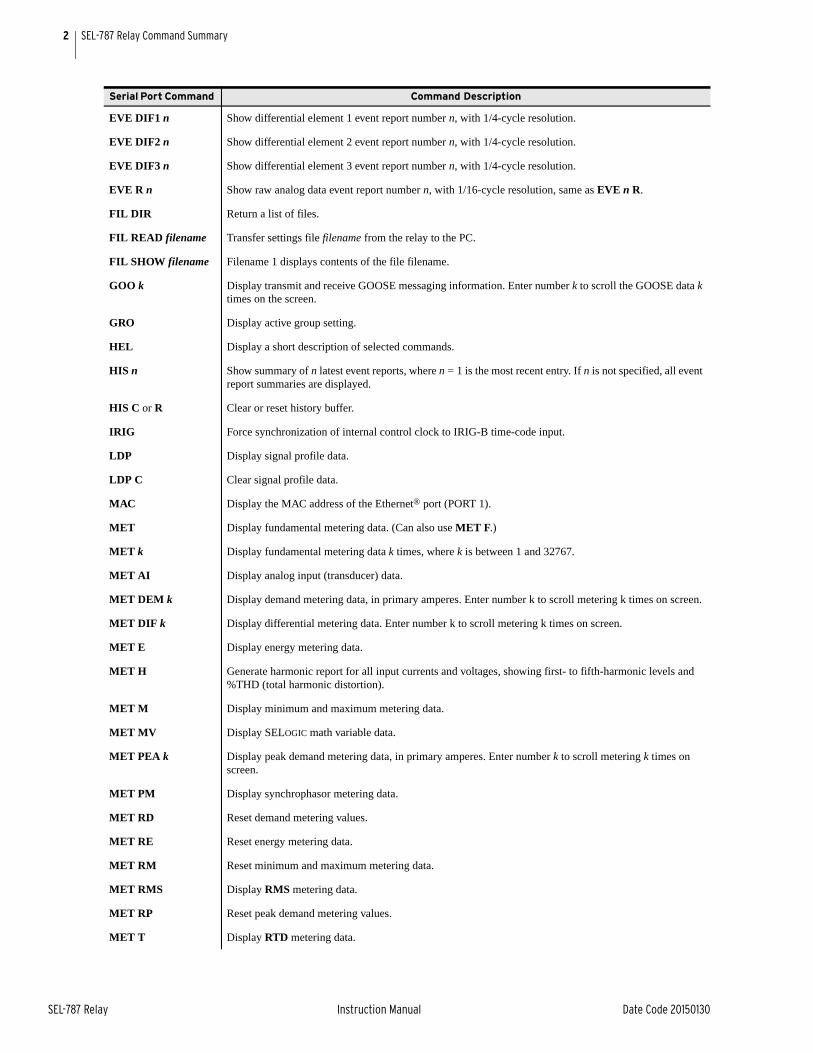
2 SEL-787 Relay Command Summary
SEL-787 Relay Instruction Manual Date Code 20150130
EVE DIF1 n Show differential element 1 event report number n, with 1/4-cycle resolution.
EVE DIF2 n Show differential element 2 event report number n, with 1/4-cycle resolution.
EVE DIF3 n Show differential element 3 event report number n, with 1/4-cycle resolution.
EVE R n Show raw analog data event report number n, with 1/16-cycle resolution, same as EVE n R.
FIL DIR Return a list of files.
FIL READ filename Transfer settings file filename from the relay to the PC.
FIL SHOW filename Filename 1 displays contents of the file filename.
GOO k Display transmit and receive GOOSE messaging information. Enter number k to scroll the GOOSE data k times on the screen.
GRO Display active group setting.
HEL Display a short description of selected commands.
HIS n Show summary of n latest event reports, where n = 1 is the most recent entry. If n is not specified, all event report summaries are displayed.
HIS C or R Clear or reset history buffer.
IRIG Force synchronization of internal control clock to IRIG-B time-code input.
LDP Display signal profile data.
LDP C Clear signal profile data.
MAC Display the MAC address of the Ethernet® port (PORT 1).
MET Display fundamental metering data. (Can also use MET F.)
MET k Display fundamental metering data k times, where k is between 1 and 32767.
MET AI Display analog input (transducer) data.
MET DEM k Display demand metering data, in primary amperes. Enter number k to scroll metering k times on screen.
MET DIF k Display differential metering data. Enter number k to scroll metering k times on screen.
MET E Display energy metering data.
MET H Generate harmonic report for all input currents and voltages, showing first- to fifth-harmonic levels and %THD (total harmonic distortion).
MET M Display minimum and maximum metering data.
MET MV Display SELOGIC math variable data.
MET PEA k Display peak demand metering data, in primary amperes. Enter number k to scroll metering k times on screen.
MET PM Display synchrophasor metering data.
MET RD Reset demand metering values.
MET RE Reset energy metering data.
MET RM Reset minimum and maximum metering data.
MET RMS Display RMS metering data.
MET RP Reset peak demand metering values.
MET T Display RTD metering data.
Serial Port Command Command Description
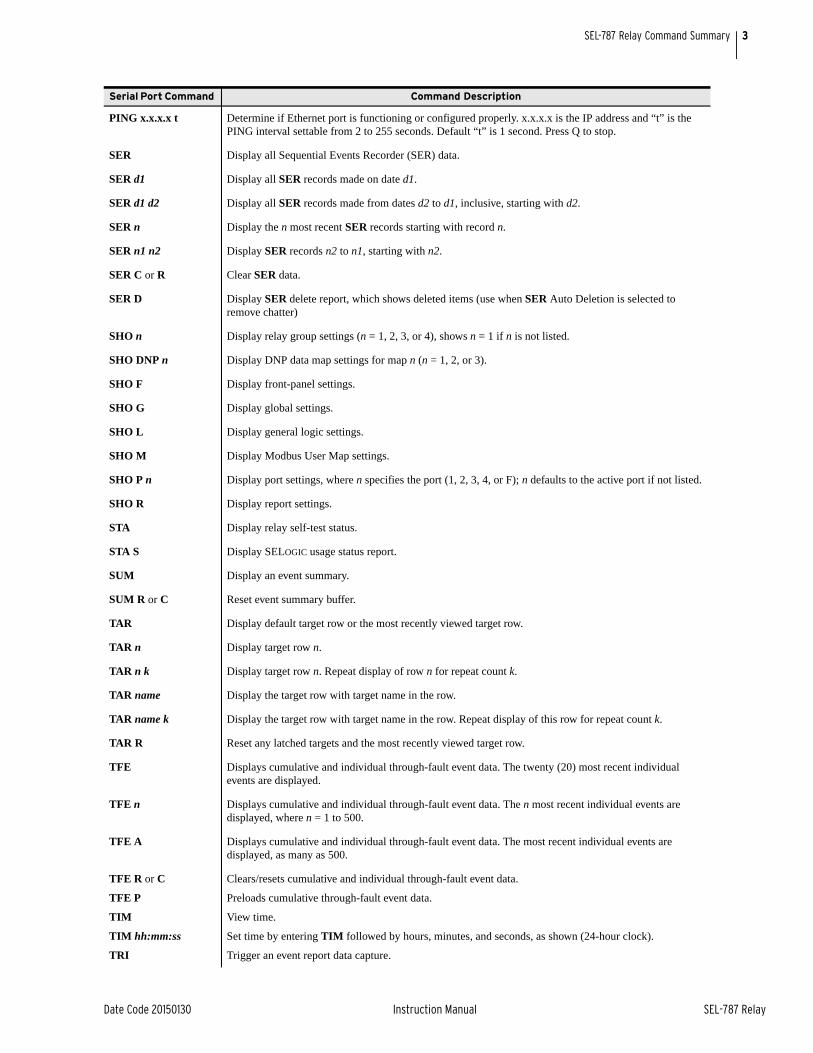
3SEL-787 Relay Command Summary
Date Code 20150130 Instruction Manual SEL-787 Relay
PING x.x.x.x t Determine if Ethernet port is functioning or configured properly. x.x.x.x is the IP address and “t” is the PING interval settable from 2 to 255 seconds. Default “t” is 1 second. Press Q to stop.
SER Display all Sequential Events Recorder (SER) data.
SER d1 Display all SER records made on date d1.
SER d1 d2 Display all SER records made from dates d2 to d1, inclusive, starting with d2.
SER n Display the n most recent SER records starting with record n.
SER n1 n2 Display SER records n2 to n1, starting with n2.
SER C or R Clear SER data.
SER D Display SER delete report, which shows deleted items (use when SER Auto Deletion is selected to remove chatter)
SHO n Display relay group settings (n = 1, 2, 3, or 4), shows n = 1 if n is not listed.
SHO DNP n Display DNP data map settings for map n (n = 1, 2, or 3).
SHO F Display front-panel settings.
SHO G Display global settings.
SHO L Display general logic settings.
SHO M Display Modbus User Map settings.
SHO P n Display port settings, where n specifies the port (1, 2, 3, 4, or F); n defaults to the active port if not listed.
SHO R Display report settings.
STA Display relay self-test status.
STA S Display SELOGIC usage status report.
SUM Display an event summary.
SUM R or C Reset event summary buffer.
TAR Display default target row or the most recently viewed target row.
TAR n Display target row n.
TAR n k Display target row n. Repeat display of row n for repeat count k.
TAR name Display the target row with target name in the row.
TAR name k Display the target row with target name in the row. Repeat display of this row for repeat count k.
TAR R Reset any latched targets and the most recently viewed target row.
TFE Displays cumulative and individual through-fault event data. The twenty (20) most recent individual events are displayed.
TFE n Displays cumulative and individual through-fault event data. The n most recent individual events are displayed, where n = 1 to 500.
TFE A Displays cumulative and individual through-fault event data. The most recent individual events are displayed, as many as 500.
TFE R or C Clears/resets cumulative and individual through-fault event data.
TFE P Preloads cumulative through-fault event data.
TIM View time.
TIM hh:mm:ss Set time by entering TIM followed by hours, minutes, and seconds, as shown (24-hour clock).
TRI Trigger an event report data capture.
Serial Port Command Command Description
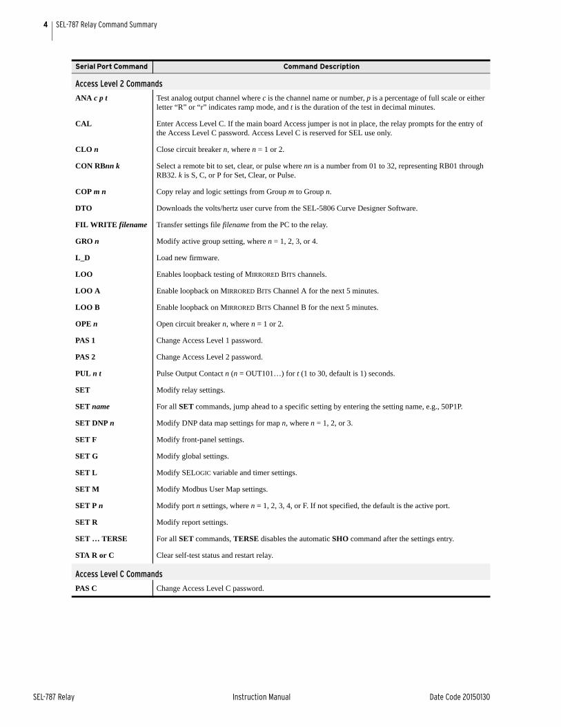
4 SEL-787 Relay Command Summary
SEL-787 Relay Instruction Manual Date Code 20150130
Access Level 2 Commands
ANA c p t Test analog output channel where c is the channel name or number, p is a percentage of full scale or either letter “R” or “r” indicates ramp mode, and t is the duration of the test in decimal minutes.
CAL Enter Access Level C. If the main board Access jumper is not in place, the relay prompts for the entry of the Access Level C password. Access Level C is reserved for SEL use only.
CLO n Close circuit breaker n, where n = 1 or 2.
CON RBnn k Select a remote bit to set, clear, or pulse where nn is a number from 01 to 32, representing RB01 through RB32. k is S, C, or P for Set, Clear, or Pulse.
COP m n Copy relay and logic settings from Group m to Group n.
DTO Downloads the volts/hertz user curve from the SEL-5806 Curve Designer Software.
FIL WRITE filename Transfer settings file filename from the PC to the relay.
GRO n Modify active group setting, where n = 1, 2, 3, or 4.
L_D Load new firmware.
LOO Enables loopback testing of MIRRORED BITS channels.
LOO A Enable loopback on MIRRORED BITS Channel A for the next 5 minutes.
LOO B Enable loopback on MIRRORED BITS Channel B for the next 5 minutes.
OPE n Open circuit breaker n, where n = 1 or 2.
PAS 1 Change Access Level 1 password.
PAS 2 Change Access Level 2 password.
PUL n t Pulse Output Contact n (n = OUT101…) for t (1 to 30, default is 1) seconds.
SET Modify relay settings.
SET name For all SET commands, jump ahead to a specific setting by entering the setting name, e.g., 50P1P.
SET DNP n Modify DNP data map settings for map n, where n = 1, 2, or 3.
SET F Modify front-panel settings.
SET G Modify global settings.
SET L Modify SELOGIC variable and timer settings.
SET M Modify Modbus User Map settings.
SET P n Modify port n settings, where n = 1, 2, 3, 4, or F. If not specified, the default is the active port.
SET R Modify report settings.
SET … TERSE For all SET commands, TERSE disables the automatic SHO command after the settings entry.
STA R or C Clear self-test status and restart relay.
Access Level C Commands
PAS C Change Access Level C password.
Serial Port Command Command Description