SEL-735_IM_20151012
400
20151012 SEL-735 Power Quality and Revenue Meter Instruction Manual *PM735-01-NB*
description
Manual SEL-735
Transcript of SEL-735_IM_20151012

20151012
SEL-735Power Quality and
Revenue Meter
Instruction Manual
*PM735-01-NB*

SEL-735 Meter Instruction Manual Date Code 20151012
© 2011–2015 by Schweitzer Engineering Laboratories, Inc. All rights reserved.
All brand or product names appearing in this document are the trademark or registered trademark of their respective holders. No SEL trademarks may be used without written permission. SEL products appearing in this document may be covered by U.S. and Foreign patents.
Schweitzer Engineering Laboratories, Inc. reserves all rights and benefits afforded under federal and international copyright and patent laws in its products, including without limitation software, firmware, and documentation.
The information in this document is provided for informational use only and is subject to change without notice. Schweitzer Engineering Laboratories, Inc. has approved only the English language document.
This product is covered by the standard SEL 10-year warranty. For warranty details, visit www.selinc.com or contact your customer service representative. PM735-01

Date Code 20151012 Instruction Manual SEL-735 Meter
Table of ContentsList of Tables ........................................................................................................................................................ v
List of Figures ..................................................................................................................................................... ix
Preface.................................................................................................................................................................xiii
Section 1: Introduction and SpecificationsOverview ......................................................................................................................................................... 1.1SEL-735 Meter Forms and Models ................................................................................................................. 1.1Applications..................................................................................................................................................... 1.3Hardware Connection Features ....................................................................................................................... 1.4Communications Connections......................................................................................................................... 1.5Specifications .................................................................................................................................................. 1.6
Section 2: InstallationOverview ......................................................................................................................................................... 2.1Mount Meter .................................................................................................................................................... 2.2Make Rear-Panel Connections ........................................................................................................................ 2.5Configure and Check Meter Status.................................................................................................................. 2.8
Section 3: Front-Panel OperationOverview ......................................................................................................................................................... 3.1Access Levels .................................................................................................................................................. 3.1Front-Panel Operations.................................................................................................................................... 3.2Normal Operation............................................................................................................................................ 3.5Menus and Operations..................................................................................................................................... 3.6Display Points.................................................................................................................................................. 3.8
Section 4: ACSELERATOR QuickSetOverview ......................................................................................................................................................... 4.1Settings ............................................................................................................................................................ 4.1Using the Human Machine Interface (HMI) ................................................................................................... 4.9
SEL-735 Settings Sheets
Section 5: MeteringOverview ......................................................................................................................................................... 5.1Form Factor Support........................................................................................................................................ 5.1IEC 61000-4-30 Testing and Measurement Techniques—Power Quality Measurement Methods................. 5.2Measurement Aggregation .............................................................................................................................. 5.2Four-Quadrant VAR Metering......................................................................................................................... 5.5Instrument Transformer Compensation........................................................................................................... 5.6Frequency Tracking ......................................................................................................................................... 5.9Demand Metering.......................................................................................................................................... 5.10Time-of-Use (TOU)....................................................................................................................................... 5.19TOU Setup..................................................................................................................................................... 5.19TOU Glossary................................................................................................................................................ 5.29Energy Metering ............................................................................................................................................ 5.31Minimum/Maximum Metering...................................................................................................................... 5.36Crest Factor Metering.................................................................................................................................... 5.38Harmonic Metering ....................................................................................................................................... 5.39Flicker Metering ............................................................................................................................................ 5.45Transformer/Line Loss Compensation .......................................................................................................... 5.45Configurable Registers .................................................................................................................................. 5.51

ii
SEL-735 Meter Instruction Manual Date Code 20151012
Table of Contents
Voltage, Current, and Power Calculations .....................................................................................................5.55
Section 6: LoggingIntroduction......................................................................................................................................................6.1Load Profile Report..........................................................................................................................................6.1Event Reports Overview ..................................................................................................................................6.5Waveform Capture Event Reports ...................................................................................................................6.6Sequential Events Recorder (SER) Report ......................................................................................................6.8Voltage Sag/Swell/Interruption (VSSI) Report..............................................................................................6.11
Section 7: Inputs/Outputs and SELOGIC Control EquationsOverview..........................................................................................................................................................7.1Inputs/Outputs..................................................................................................................................................7.2SELOGIC Control Equations ..........................................................................................................................7.10
Section 8: CommunicationsOverview..........................................................................................................................................................8.1Communications Options ................................................................................................................................8.1Port Connector and Communications Cables ..................................................................................................8.5Communications Protocols ..............................................................................................................................8.6Command Summary ......................................................................................................................................8.14Command Explanations .................................................................................................................................8.15
SEL-735 Meter Command Summary
Section 9: Testing and TroubleshootingOverview..........................................................................................................................................................9.1TEST Mode Characteristics.............................................................................................................................9.1Testing Philosophy...........................................................................................................................................9.2Testing Methods and Tools ..............................................................................................................................9.3Gain Adjustment ............................................................................................................................................9.14Meter Self-Tests .............................................................................................................................................9.16Meter Troubleshooting...................................................................................................................................9.17Factory Assistance .........................................................................................................................................9.18
Appendix A: Firmware and Manual VersionsFirmware .........................................................................................................................................................A.1Instruction Manual ..........................................................................................................................................A.5
Appendix B: SEL-735 Upgrade InstructionsOverview......................................................................................................................................................... B.1Installation ...................................................................................................................................................... B.2Upgrade Procedure ......................................................................................................................................... B.2
Appendix C: SEL Communications ProcessorsSEL Communications Protocols ..................................................................................................................... C.1SEL Communications Processor .................................................................................................................... C.3SEL Communications Processor and Meter Architecture .............................................................................. C.5SEL Communications Processor Example ..................................................................................................... C.7
Appendix D: Distributed Network ProtocolOverview.........................................................................................................................................................D.1Configuration ..................................................................................................................................................D.4EIA-232 Physical Layer Operation...............................................................................................................D.14Ethernet Operation ........................................................................................................................................D.15DNP Channels...............................................................................................................................................D.16Data Access Method .....................................................................................................................................D.16Device Profile ...............................................................................................................................................D.17Object Table ..................................................................................................................................................D.18

iii
Date Code 20151012 Instruction Manual SEL-735 Meter
Table of Contents
Appendix E: Modbus Communications ProtocolOverview .........................................................................................................................................................E.1Modbus RTU Communications Protocol ........................................................................................................E.1Modbus TCP..................................................................................................................................................E.10Modbus Data Types .......................................................................................................................................E.11Modbus Register Map ...................................................................................................................................E.13
Appendix F: MIRRORED BITS CommunicationsOverview ......................................................................................................................................................... F.1Operation ......................................................................................................................................................... F.1MIRRORED BITS Protocol for Pulsar 9600 Baud Modem................................................................................ F.4Settings ............................................................................................................................................................ F.4
Appendix G: Analog Quantities and Device Word BitsOverview ........................................................................................................................................................ G.1Basic Analog Quantity List ............................................................................................................................ G.3Advanced Analog Quantity List ................................................................................................................... G.10Device Word Bits (Used in SELOGIC Control Equations) ........................................................................... G.18
Appendix H: IEC 61850 CommunicationsFeatures........................................................................................................................................................... H.1Introduction to IEC 61850.............................................................................................................................. H.2IEC 61850 Operation...................................................................................................................................... H.3IEC 61850 Configuration ............................................................................................................................. H.13Logical Node Extensions.............................................................................................................................. H.15Logical Nodes............................................................................................................................................... H.17
Appendix I: SynchrophasorsOverview .......................................................................................................................................................... I.1Synchrophasor Measurement ........................................................................................................................... I.2General Settings for Synchrophasors ............................................................................................................... I.3Ethernet Port Settings for Synchrophasor Protocol IEEE C37.118.2 .............................................................. I.7Synchrophasor Device Word Bits..................................................................................................................... I.9View Synchrophasors Using the MET PM Command...................................................................................I.10IEEE C37.118.2 Synchrophasor Protocol ...................................................................................................... I.11
Glossary
SEL-735 Meter Command Summary

This page intentionally left blank

Date Code 20151012 Instruction Manual SEL-735 Meter
List of TablesTable 1.1 SEL-735 Form Numbers ........................................................................................................ 1.1Table 1.2 SEL-735 Compliance With IEC 61000-4-30 Power Quality Standard.................................. 1.2Table 1.3 SEL-735 Waveform Capture Settings Options for Event Reports ......................................... 1.2Table 2.1 Required Rear-Panel Connections.......................................................................................... 2.6Table 2.2 Essential Initial Settings ......................................................................................................... 2.9Table 2.3 Serial Port Pin Function ....................................................................................................... 2.10Table 2.4 Default SEL-735 Settings and Required ACSELERATOR QuickSet Communications
Parameters ........................................................................................................................... 2.12Table 2.5 Optical Probe Required Communications Settings.............................................................. 2.13Table 3.1 Front-Panel Pushbutton Functions ......................................................................................... 3.6Table 3.2 SEL-735 Front-Panel Menu Structure.................................................................................... 3.7Table 3.3 Default Normal and Alternate Display Points........................................................................ 3.9Table 3.4 Display Point Setting Definitions......................................................................................... 3.10Table 3.5 Display Point Formatting ..................................................................................................... 3.11Table 5.1 Device Word Bits Associated With Voltage Sags, Swells, and Interruptions ........................ 5.4Table 5.2 Default Load Profile Recorder Aggregated Data ................................................................... 5.5Table 5.3 Four-Quadrant Device Word Bits........................................................................................... 5.6Table 5.4 Example Current Transformer Test Data ............................................................................... 5.7Table 5.5 Demand and Peak Demand Metering Values....................................................................... 5.10Table 5.6 Demand Meter Settings and Settings Ranges ...................................................................... 5.13Table 5.7 Time = 5-Minute Intervals.................................................................................................... 5.14Table 5.8 Time = 10-Minute Intervals.................................................................................................. 5.14Table 5.9 Time = 15-Minute Intervals.................................................................................................. 5.14Table 5.10 Present and Peak Demand Values ........................................................................................ 5.17Table 5.11 Available Time-of-Use Data................................................................................................. 5.27Table 5.12 Load Profile Recorder Scaling ............................................................................................. 5.32Table 5.13 Example ANGCUT Setting.................................................................................................. 5.35Table 5.14 Minimum Required Magnitudes for Harmonic Percentage Calculations ............................ 5.40Table 5.15 Transformer and Line Loss Adjustments ............................................................................. 5.46Table 5.16 Required User Input ............................................................................................................. 5.47Table 5.17 Analog Quantities: Transformer and Line Losses................................................................ 5.48Table 5.18 Configurable Register Attributes.......................................................................................... 5.51Table 5.19 Configurable Register Spreadsheet Example ....................................................................... 5.54Table 5.20 Starting Current Type Setting Behavior ............................................................................... 5.55Table 5.21 Fundamental-Only Power..................................................................................................... 5.57Table 5.22 Time Source Classifications for the SEL-735 ...................................................................... 5.61Table 6.1 Load Profile Recorder Settings .............................................................................................. 6.1Table 6.2 LDP LDFUNC Recorder Function Description..................................................................... 6.2Table 6.3 Billing Recorder (LDP Recorder One) Scaling...................................................................... 6.2Table 6.4 LDP Field Format................................................................................................................... 6.5Table 6.5 State of the Voltage Sag/Swell/Interruption Device Word Bits............................................ 6.13Table 6.6 Status VSSI Column............................................................................................................. 6.13Table 7.1 SEL-735 Logic Inputs and Output Model Reference............................................................. 7.2Table 7.2 KYZ Output Settings and Ranges .......................................................................................... 7.2Table 7.3 Output Contact Settings and Default Settings........................................................................ 7.5Table 7.4 Analog Output Settings and Default Settings ........................................................................ 7.6Table 7.5 Input Debounce Default Settings and Valid Ranges .............................................................. 7.8Table 7.6 Remote Bit States ................................................................................................................... 7.9Table 7.7 SELOGIC Control Equation Inputs/Settings and Outputs..................................................... 7.10Table 7.8 Operator Precedence ............................................................................................................ 7.11Table 7.9 Latch Bit Settings and Default Settings ............................................................................... 7.12Table 7.10 Latch Bit Logic Table........................................................................................................... 7.12Table 7.11 SELOGIC Control Equation Settings and Default Settings................................................... 7.15Table 7.12 SELOGIC Control Equation Counter Inputs ......................................................................... 7.17

vi List of Tables
SEL-735 Meter Instruction Manual Date Code 20151012
Table 7.13 SELOGIC Control Equation Counter Outputs .......................................................................7.18Table 8.1 SEL-735 Meter Models and Available Main Board Communications Options .....................8.1Table 8.2 SEL-735 Meter Models and Available Slot C SELECT Board Communications Options .....8.2Table 8.3 Modem Settings ......................................................................................................................8.2Table 8.4 Useful AT Commands ............................................................................................................8.3Table 8.5 Useful Dialing Modifiers ........................................................................................................8.4Table 8.6 Ethernet Port LED Description...............................................................................................8.5Table 8.7 Port Pinout Functions .............................................................................................................8.6Table 8.8 SEL-735 Communications Cables..........................................................................................8.6Table 8.9 Serial Port Automatic Messages.............................................................................................8.9Table 8.10 Settings Associate With SNTP .............................................................................................8.13Table 9.1 Meter Testing Features ...........................................................................................................9.3Table 9.2 TEST Mode Quantities ...........................................................................................................9.4Table 9.3 TEST Mode Options...............................................................................................................9.8Table 9.4 Main Board Jumpers.............................................................................................................9.14Table 9.5 Meter Self-Tests....................................................................................................................9.16Table A.1 Firmware Revision History....................................................................................................A.2Table A.2 Instruction Manual Revision History.....................................................................................A.5Table C.1 Supported Serial Command Sets ........................................................................................... C.1Table C.2 Compressed ASCII Commands............................................................................................. C.2Table C.3 SEL-735 Fast Meter Commands ........................................................................................... C.4Table C.4 SEL Communications Processors Protocol Interfaces .......................................................... C.5Table C.5 SEL Communications Processor Port 1 Settings................................................................... C.7Table C.6 SEL Communications Processor Data Collection Automessages ......................................... C.8Table C.7 SEL Communications Processor Port 1 Automatic Messaging Settings .............................. C.8Table C.8 SEL Communications Processor Port 1 Region Map............................................................ C.8Table D.1 VSSI Summary Record Status Report Definitions ................................................................D.3Table D.2 VSSI Summary ITIC Region Definitions..............................................................................D.3Table D.3 SEL-735 DNP3 Default Data Map ........................................................................................D.4Table D.4 SEL-735 DNP3 Default Variations........................................................................................D.4Table D.5 DNP3 Device Profile .............................................................................................................D.8Table D.6 DNP-IP Specific Settings ....................................................................................................D.15Table D.7 Data Access Methods ..........................................................................................................D.16Table D.8 SEL-735 DNP3 Device Profile............................................................................................D.17Table D.9 SEL-735 DNP Object List ...................................................................................................D.18Table D.10 Control Field........................................................................................................................D.19Table E.1 Modbus Query Fields ............................................................................................................ E.1Table E.2 Modbus Function Codes ........................................................................................................ E.2Table E.3 Modbus Exception Codes ...................................................................................................... E.2Table E.4 Modbus Exception Code Format ........................................................................................... E.2Table E.5 01h Read Coil Status Commands .......................................................................................... E.3Table E.6 Device Responses to 01h Read Coil Query Errors ................................................................ E.3Table E.7 02h Read Input Status Command .......................................................................................... E.4Table E.8 Device Input Coils ................................................................................................................. E.4Table E.9 Device Responses to 02h Read Input Query Errors .............................................................. E.4Table E.10 03h Read Holding Register Command .................................................................................. E.5Table E.11 Device Responses to 03h Read Holding Register Query Errors ........................................... E.5Table E.12 04h Read Holding Register Command .................................................................................. E.6Table E.13 Device Responses to 04h Read Holding Register Query Errors ........................................... E.6Table E.14 05h Force Single Coil Command .......................................................................................... E.6Table E.15 SEL-735 Device Output Coils (FC05h) ................................................................................ E.7Table E.16 Device Responses to 05h Force Singe Coil Query Errors ..................................................... E.7Table E.17 06h Preset Single Register Command ................................................................................... E.7Table E.18 Device Responses to 06h Preset Single Register Query Errors............................................. E.7Table E.19 10h Preset Multiple Registers Command .............................................................................. E.8Table E.20 Device Responses to 10h Preset Multiple Registers Query Errors........................................ E.8Table E.21 Modbus TCP Message Format ............................................................................................ E.10Table E.22 Modbus TCP Message Format Definitions ......................................................................... E.11

viiList of Tables
Date Code 20151012 Instruction Manual SEL-735 Meter
Table E.23 Modbus Data Types..............................................................................................................E.11Table E.24 Modbus Enumeration Definitions ........................................................................................E.12Table E.25 Modbus BITMAP Definitions..............................................................................................E.12Table E.26 Modbus Register Map ..........................................................................................................E.13Table F.1 Using the SPEED Setting to Control MIRRORED BIT Rates .................................................. F.4Table F.2 Matching RX_ID of Local Meter to TX_ID of Remote Meter.............................................. F.5Table G.1 Analog Quantities Available to Internal Interface Types......................................................................G.1Table G.2 Voltage, Current, and Power.................................................................................................. G.3Table G.3 Demand, Peak Demand, Previous Demand........................................................................... G.4Table G.4 Energy ................................................................................................................................... G.7Table G.5 Frequency .............................................................................................................................. G.9Table G.6 Power Factor.......................................................................................................................... G.9Table G.7 Aggregation ......................................................................................................................... G.10Table G.8 Advanced: Configured Registers......................................................................................... G.11Table G.9 Advanced: Date and Time ................................................................................................... G.11Table G.10 Advanced: Diagnostics........................................................................................................ G.11Table G.11 Advanced: DNP Remote Analog Outputs........................................................................... G.11Table G.12 Advanced: Flicker ............................................................................................................... G.11Table G.13 Advanced: Fundamental Only............................................................................................. G.12Table G.14 Advanced: Harmonics ......................................................................................................... G.13Table G.15 Advanced: Maximum/Minimum, Crest Factor ................................................................... G.14Table G.16 Advanced: Monthly Frozen/Consumed Values................................................................... G.14Table G.17 Advanced: SELOGIC............................................................................................................ G.15Table G.18 Advanced: Symmetrical Components ................................................................................. G.15Table G.19 Advanced: Time-of-Use Metering ...................................................................................... G.15Table G.20 Advanced: Transformer and Line Losses............................................................................ G.17Table G.21 Advanced: Transformer Settings ......................................................................................... G.17Table G.22 Advanced: Voltage and Current Imbalance and Average.................................................... G.18Table G.23 Advanced: Voltage and Frequency Deviation ..................................................................... G.18Table G.24 SEL-735 Device Word Bits ................................................................................................. G.18Table G.25 SEL-735 Device Word Bit Definitions................................................................................ G.21Table H.1 IEC 61850 Document Set...................................................................................................... H.2Table H.2 Example IEC 61850 Descriptor Components ....................................................................... H.4Table H.3 Functional Constraints........................................................................................................... H.4Table H.4 SEL-735 Logical Devices ..................................................................................................... H.4Table H.5 Buffered Report Control Block Client Access ...................................................................... H.8Table H.6 Unbuffered Report Control Block Client Access.................................................................. H.9Table H.7 IEC 61850 Settings.............................................................................................................. H.13Table H.8 New Logical Node Extensions ............................................................................................ H.15Table H.9 Flicker Measurement Logical Node Class Definition......................................................... H.15Table H.10 Voltage Variation Logical Node Class Definition ............................................................... H.16Table H.11 Energy Quantities Logical Node Class Definition .............................................................. H.16Table H.12 Metering Statistics Logical Node Class Definition............................................................. H.17Table H.13 Logical Device: ANN (Annunciation) ................................................................................ H.17Table H.14 Logical Device: CON (Remote Control)............................................................................. H.20Table H.15 Logical Device: MET (Metering)........................................................................................ H.20Table I.1 PMU Settings in the SEL-735 for IEEE C37.118 Protocol in General Settings..................... I.4Table I.2 User-Defined Digital Status Word Selected by the NUMDSW Setting.................................. I.7Table I.3 SEL-735 Ethernet Port Settings for Synchrophasors .............................................................. I.8Table I.4 Synchrophasor Trigger Device Word Bits............................................................................. I.10Table I.5 Time-Synchronization Device Word Bits.............................................................................. I.10Table I.6 Synchrophasor Order in Data Stream (Voltages and Currents in PHASORS Field) ............ I.12

This page intentionally left blank

Date Code 20151012 Instruction Manual SEL-735 Meter
List of FiguresFigure 1.1 SEL-735 Applied at Billing Points Throughout the Power System....................................... 1.3Figure 1.2 SEL-735 Inputs, Outputs, and Communications Ports .......................................................... 1.4Figure 1.3 SEL-735 Communications Connection Examples................................................................. 1.5Figure 2.1 SEL-735 Horizontal Panel-Mount Dimensions ..................................................................... 2.2Figure 2.2 SEL-735 Vertical Panel-Mount Dimensions .......................................................................... 2.2Figure 2.3 SEL-735 Easily Extractable Meter Panel-Mount Dimensions............................................... 2.3Figure 2.4 Outdoor Enclosure Dimensions ............................................................................................. 2.4Figure 2.5 Grounding Terminal Symbol.................................................................................................. 2.4Figure 2.6 Form 9, 3-Element, Four-Wire Wye Wiring Diagram............................................................ 2.5Figure 2.7 Form 5, 2-Element, Three-Wire Delta Wiring Diagram ........................................................ 2.5Figure 2.8 Form 36, 2 1/2-Element, Four-Wire Wye Wiring Diagram ................................................... 2.6Figure 2.9 ACSELERATOR QuickSet Communication Parameters ........................................................ 2.11Figure 2.10 ACSELERATOR QuickSet Communications Activity and Status.......................................... 2.13Figure 2.11 SEL-735 Model Option Table .............................................................................................. 2.14Figure 2.12 Identifier and Scaling Settings ............................................................................................. 2.15Figure 2.13 Settings Group/Class Select to Send Window...................................................................... 2.16Figure 3.1 SEL-735 Horizontal Unit Front-Panel Layout ....................................................................... 3.2Figure 3.2 SEL-735 Vertical Unit Front-Panel Layout............................................................................ 3.3Figure 3.3 Graphical Logic Editor Lockout Latch Control Example ...................................................... 3.4Figure 3.4 Graphical Logic Editor Compile Logic Window ................................................................... 3.5Figure 3.5 Default Light Illuminated....................................................................................................... 3.5Figure 3.6 Keypad Entry Through Front-Panel LCD .............................................................................. 3.7Figure 4.1 ACSELERATOR QuickSet Initial View.................................................................................... 4.2Figure 4.2 Database Manager, Create New Database.............................................................................. 4.3Figure 4.3 Create New Settings Database Window................................................................................. 4.3Figure 4.4 Settings Editor Selection Window.......................................................................................... 4.4Figure 4.5 Device Part Number Window................................................................................................. 4.4Figure 4.6 SEL-735 Settings Editor Window and Settings Tree ............................................................. 4.5Figure 4.7 Settings Group/Class Select Window..................................................................................... 4.6Figure 4.8 Display Point Settings ............................................................................................................ 4.7Figure 4.9 Boolean Quantity Display Point Builder................................................................................ 4.8Figure 4.10 Analog Quantity Display Point Configuration Example........................................................ 4.8Figure 4.11 DNP Map Builder Window .................................................................................................... 4.9Figure 4.12 Device Overview HMI Window........................................................................................... 4.10Figure 4.13 Phasors HMI Window .......................................................................................................... 4.11Figure 4.14 Metering HMI Window With RMS Quantities Shown ........................................................ 4.12Figure 4.15 Synchrophasor HMI ............................................................................................................. 4.13Figure 4.16 Crest Factor HMI Window................................................................................................... 4.14Figure 4.17 Demand/Peak HMI Window ................................................................................................ 4.15Figure 4.18 Min/Max HMI Window ....................................................................................................... 4.16Figure 4.19 Flicker HMI Window ........................................................................................................... 4.16Figure 4.20 Status HMI Window............................................................................................................. 4.17Figure 4.21 Control Window HMI .......................................................................................................... 4.18Figure 4.22 Event History Window ......................................................................................................... 4.19Figure 4.23 Save Event Report Window.................................................................................................. 4.20Figure 4.24 ACSELERATOR Analytic Assistant Main Control Window.................................................. 4.20Figure 5.1 Selected Sag and Swell Elements in a Sequential Events Recorder ...................................... 5.4Figure 5.2 IEEE VAR Sign Convention................................................................................................... 5.5Figure 5.3 SEL-735 Power Flow Notations............................................................................................. 5.6Figure 5.4 Ratio Correction Factor vs. Calibration Point ........................................................................ 5.8Figure 5.5 Phase Angle Minutes vs. Calibration Point............................................................................ 5.9Figure 5.6 Response of Thermal, Rolling, and Block Demand Meters to a Step Input
(Setting DMTC = 15 Minutes) ......................................................................................... 5.11Figure 5.7 Voltage VS Applied to Series RC Circuit............................................................................. 5.12
x List of Figures
SEL-735 Meter Instruction Manual Date Code 20151012
Figure 5.8 PREDAL Logic.....................................................................................................................5.15Figure 5.9 Demand Current Logic Outputs ...........................................................................................5.16Figure 5.10 Demand/Peak Metering Values HMI Window .....................................................................5.17Figure 5.11 Setup Page ............................................................................................................................5.20Figure 5.12 Rate Schedules Page .............................................................................................................5.21Figure 5.13 Schedule Drop-Down Menu .................................................................................................5.21Figure 5.14 Deleting a Rate Schedule......................................................................................................5.22Figure 5.15 Renaming a Rate Schedule ...................................................................................................5.22Figure 5.16 Modifying a Rate Schedule ..................................................................................................5.23Figure 5.17 Calendar Page .......................................................................................................................5.24Figure 5.18 Calendar Entry Drop-Down Menu .......................................................................................5.25Figure 5.19 Calendar Entry Editor ...........................................................................................................5.25Figure 5.20 Calendar Entry Editor ...........................................................................................................5.25Figure 5.21 Quick Set Menu ....................................................................................................................5.26Figure 5.22 TOU Data Page.....................................................................................................................5.26Figure 5.23 Total At/Since Demand Reset...............................................................................................5.29Figure 5.24 Peak Cumulative Demand ....................................................................................................5.30Figure 5.25 Energy Metering Values HMI Window ................................................................................5.33Figure 5.26 Power Factor = ±0.02............................................................................................................5.35Figure 5.27 Min/Max Metering Values HMI Window.............................................................................5.36Figure 5.28 FAULT and DFAULT Device Word Bit Logic .....................................................................5.37Figure 5.29 Crest Factor Metering Values HMI Window ........................................................................5.38Figure 5.30 Interharmonics vs. Integer-Harmonics Example ..................................................................5.42Figure 5.31 Harmonics HMI Toolbar.......................................................................................................5.44Figure 5.32 Flicker HMI Window............................................................................................................5.45Figure 5.33 Meter and Billing Positions ..................................................................................................5.46Figure 5.34 Transformer and Line Loss Values in Configurable Registers .............................................5.47Figure 5.35 Configurable Registers Settings Window .............................................................................5.53Figure 5.36 Front-Panel LCD Display Point Example ............................................................................5.54Figure 5.37 Configurable Registers Configuration Tool..........................................................................5.55Figure 5.38 Time Changes Relative to the TIME_CHG Setting and Time Interval Boundaries.............5.62Figure 6.1 LDP Settings Interface............................................................................................................6.3Figure 6.2 LDP HMI Window .................................................................................................................6.3Figure 6.3 Trigger an Event Via ACSELERATOR QuickSet HMI Control Window .................................6.7Figure 6.4 Clear Events From Meter........................................................................................................6.8Figure 6.5 SER List Builder.....................................................................................................................6.9Figure 6.6 SER HMI Window................................................................................................................6.10Figure 6.7 Clear SER Report From Meter .............................................................................................6.11Figure 6.8 Example VSSI Response in ACSELERATOR QuickSet.........................................................6.12Figure 6.9 Example Voltage Sag/Swell/Interruption (VSSI) Report (Meter Form 9) ...........................6.14Figure 7.1 KYZ Pulse Pickup ..................................................................................................................7.3Figure 7.2 Pulse Output Contact Example...............................................................................................7.5Figure 7.3 Analog Output Settings Example ...........................................................................................7.7Figure 7.4 Example Operation of Optoisolated Inputs IN101–IN102.....................................................7.7Figure 7.5 Example Operation of Optoisolated Inputs IN401–IN404, Extra I/O Board .........................7.8Figure 7.6 Contact I/O Status Shown in ACSELERATOR QuickSet HMI Device Overview Window .....7.9Figure 7.7 Remote Control Switches Drive Remote Bits RB01–RB16...................................................7.9Figure 7.8 Control Remote Bits Through ACSELERATOR QuickSet HMI ............................................7.10Figure 7.9 Traditional Latching Relay ...................................................................................................7.12Figure 7.10 Latch Control Switches Drive Latch Bits LT01–LT16.........................................................7.12Figure 7.11 Battery Charger Health Status Contact Pulses Input IN102 to Enable/Disable
ALARM Output Contact...................................................................................................7.13Figure 7.12 Single Input to Control ALARM..........................................................................................7.13Figure 7.13 Latch Control Switch Operation Time Line .........................................................................7.14Figure 7.14 Latch Control Switch (With Time-Delay Feedback) Operation Time Line .........................7.14Figure 7.15 SELOGIC Control Equation Variables and Timers................................................................7.16Figure 7.16 Example Use of SELOGIC Variables/Timers ........................................................................7.16Figure 7.17 Math Variables Shown in HMI Math Window .....................................................................7.17

xiList of Figures
Date Code 20151012 Instruction Manual SEL-735 Meter
Figure 7.18 SELOGIC Variable SV10 Timing Logic................................................................................ 7.19Figure 7.19 SELOGIC Control Equation Counter Example ..................................................................... 7.19Figure 7.20 MIRRORED BITS Channel A.................................................................................................. 7.20Figure 7.21 MIRRORED BITS Targets Shown in ACSELERATOR QuickSet HMI ..................................... 7.21Figure 7.22 Reset Trigger Equation Settings Example............................................................................ 7.21Figure 7.23 Graphical Logic Editor Toolbar ........................................................................................... 7.22Figure 7.24 Graphic Logic Editor Window ............................................................................................. 7.23Figure 7.25 Graphical Logic Editor Element Control ............................................................................. 7.23Figure 8.1 Factory-Default AT String...................................................................................................... 8.3Figure 8.2 DB-9 Connector Pinout for EIA-232 and EIA-485 Serial Ports ............................................ 8.5Figure 8.3 Ethernet Port Status LEDs...................................................................................................... 8.5Figure 8.4 GOOSE Command Response............................................................................................... 8.18Figure 9.1 Typical TEST Mode Connections for a Form 9 SEL-735 Using a Single-Phase
Test Source.......................................................................................................................... 9.5Figure 9.2 Typical TEST Mode Connections for a Form 36 SEL-735 Using a Single-Phase
Test Source.......................................................................................................................... 9.6Figure 9.3 Typical TEST Mode Connections for a Form 9 SEL-735 Using a Three-Phase Test
Source ................................................................................................................................. 9.7Figure 9.4 TEST Mode Control Pushbutton............................................................................................ 9.9Figure 9.5 TEST Mode HMI ................................................................................................................... 9.9Figure 9.6 ACSELERATOR QuickSet HMI TEST Mode Display........................................................... 9.10Figure 9.7 Solid-State Output Contact KYZ Options............................................................................ 9.12Figure 9.8 Jumper Header—Password and Breaker Jumpers................................................................ 9.13Figure C.1 SEL Communications Processor Star Integration Network ...................................................C.3Figure C.2 Multitiered SEL Communications Processor Architecture....................................................C.4Figure C.3 Enhancing Multidrop Networks With SEL Communications Processors..............................C.6Figure C.4 Example SEL Meter and SEL Communications Processor Configuration............................C.7Figure D.1 Mapping DNP Binary Outputs.............................................................................................. D.5Figure D.2 Reorder DNP Binary Outputs ............................................................................................... D.6Figure D.3 DNP Map Builder.................................................................................................................. D.7Figure D.4 Scaling and Dead Band Window........................................................................................... D.7Figure D.5 Per-Point Scaling and Dead Band Applied ........................................................................... D.7Figure H.1 SEL-735 Datasets.................................................................................................................. H.6Figure H.2 SEL-735 Predefined Reports................................................................................................. H.7Figure I.1 Phase Angle of Waveform at Two Time Instances ................................................................. I.2Figure I.2 Waveform at Meter Terminals May Have a Phase Shift ......................................................... I.6Figure I.3 Correction of Measured Phase Angle...................................................................................... I.6Figure I.4 TCP Connection ...................................................................................................................... I.8Figure I.5 UDP_T and UDP_U Connections...........................................................................................I.9Figure I.6 UDP_S Connection ................................................................................................................. I.9Figure I.7 Sample MET PM Command Response................................................................................. I.11

This page intentionally left blank

Date Code 20151012 Instruction Manual SEL-735 Meter
Preface
Manual OverviewThe SEL-735 Power Quality and Revenue Meter provides high-accuracy revenue metering and power quality metering for electric utilities and industrial applications. The SEL-735 has flexible, user-programmable SELOGIC® control equations that include mathematical functions. The metering and control functions are ideal for complete automation applications.
The SEL-735 Power Quality and Revenue Meter Instruction Manual describes common aspects of power quality and revenue meter applications. It includes the necessary information to install, set, test, and operate the meter and more detailed information about settings and commands.
An overview of each manual section and topics follows.
Preface. This section describes the manual organization and the conventions used to present information.
Section 1: Introduction and Specifications. This section describes the basic features and functions of the SEL-735 Meter; lists the meter specifications.
Section 2: Installation. This section describes how to mount and wire the SEL-735 Meter, including connections for several applications; includes the SEL-735 front- and rear-panel diagrams.
Section 3: Front-Panel Operation. This section describes security access levels, menu and control pushbutton operations, LCD display points functionality, and normal front- panel indications.
Section 4: ACSELERATOR QuickSet. This section describes how to use the ACSELERATOR® QuickSet® SEL-5030 Software with the SEL-735.
Section 5: Metering. This section describes the operation of instantaneous metering, demand metering, energy metering, crest factor metering, minimum/maximum metering, transformer/line loss compensation, and harmonic metering.
Section 6: Logging. This section describes how to log and retrieve data via the load profile recorders, waveform capture event reports, Sequential Events Recorders, and voltage sag swell and interruption reports.
Section 7: Inputs/Outputs and SELOGIC Control Equations. This section describes the operation of optoisolated inputs IN101–IN102 and IN401–IN404; remote control switches (remote bit outputs RB01–RB16); latch control switches (latch bit outputs LT01–LT16); programmable timers (timer outputs SV01T–SV16T); math variables (math variable outputs MV01–MV16); output contacts OUT101–OUT103 and OUT401–OUT404; and rotating displays.
Section 8: Communications. This section explains port options and configurations, internal modem use, communications cables, basic protocol descriptions, and summarizes ASCII commands.
Section 9: Testing and Troubleshooting. This section describes how to perform a meter calibration check through each available interface, test wiring, basic testing philosophies, gain adjustments, error codes, and common troubleshooting techniques.

xiv
SEL-735 Meter Instruction Manual Date Code 20151012
PrefaceSafety Information
Appendix A: Firmware and Manual Versions. This appendix lists the present meter firmware version and details differences among the present and previous versions. Provides a record of changes made to the instruction manual since the initial release.
Appendix B: SEL-735 Upgrade Instructions. This appendix describes how to perform a firmware upgrade to the meter.
Appendix C: SEL Communications Processors. This appendix describes how SEL communications processors and PC software use SEL protocols optimized for performance and reliability.
Appendix D: Distributed Network Protocol. This appendix describes DNP and includes the DNP Port Settings Sheets.
Appendix E: Modbus Communications Protocol. This appendix describes Modbus® RTU communications features supported by the SEL-735 Meter communications port.
Appendix F: MIRRORED BITS Communications. This appendix contains a summary of MIRRORED BITS® settings and describes how MIRRORED BITS function with the SEL-735.
Appendix G: Analog Quantities and Device Word Bits. This appendix contains a summary of analog quantities available for use in load profile, displaying points, etc. and how to set the control elements (Device Word bits) in the SELOGIC control equations.
SEL-735 Meter Command Summary. This section summarizes all ASCII commands.
Safety InformationDangers, Warnings, and Cautions
This manual uses three kinds of hazard statements, defined as follows:
Safety Symbols The following symbols are often marked on SEL products.
DANGERIndicates an imminently hazardous situation that, if not avoided, will result in death or serious injury.
WARNINGIndicates a potentially hazardous situation that, if not avoided, could result in death or serious injury.
CAUTIONIndicates a potentially hazardous situation that, if not avoided, may result in minor or moderate injury or equipment damage.
CAUTIONRefer to accompanying documents.
ATTENTIONSe reporter à la documentation.
Earth (ground) Terre
Protective earth (ground) Terre de protection

xv
Date Code 20151012 Instruction Manual SEL-735 Meter
PrefaceSafety Information
Safety Marks The following statements apply to this device.
Hazardous Locations Approval
In North America, the meter is approved for Class I, Division 2, Groups A, B, C, D, and T4 in the –40°C to +70°C (–40°F to +158°F) range.
Direct current Courant continu
Alternating current Courant alternatif
Both direct and alternating current Courant continu et alternatif
Instruction manual Manuel d’instructions
General Safety Marks
For use in Pollution Degree 2 environment. Pour l'utilisation dans un environnement de Degré de Pollution 2.
Ambient air temperature shall not exceed 40°C (104°F). La température ambiante de l'air ne doit pas dépasser 40°C (104°F).
Terminal Ratings Valeurs nominales des bornes
Wire MaterialCopper
Matériau de filCuivre
Wire SizeCT connections: 12–26 AWG
Calibre de filConnexions du TC : 12–26 AWG
Tightening TorqueCT terminal blocks: 1.0–1.4 Nm (9.0–12.0 in-lbs)Other terminal blocks: 0.79 Nm (7.0 in-lbs)
Couple de SerrageCT borniers : 1,0–1,4 Nm (9,0–12,0 livres-pouce)Autres borniers : 0,79 Nm (7,0 livres-pouce)
Hazardous Locations Safety Marks
WARNING – EXPLOSION HAZARDOpen circuit before removing cover.
AVERTISSEMENT – DANGER D'EXPLOSIONOuvrir le circuit avant de déposer le couvercle.
WARNING – EXPLOSION HAZARDSubstitution of components may impair suitability for Class I, Division 2.
AVERTISSEMENT – DANGER D'EXPLOSIONLa substitution de composants peut détériorer la conformité à Classe I, Division 2.
Operating temperature range: –40°C to +85°C (–40°F to +185°F).
Plage de température de fonctionnement : –40°C à +85°C (–40°F à +185°F).
Hazardous Locations operating temperature range: –20°C to +40°C (–4°F to +104°F).
Emplacements Plage de température de fonctionnement d’emplacements dangereux : –20°C à +40°C (–4°F à +104°F).
Other Safety Marks (Sheet 1 of 2)
DANGERContact with instrument terminals can cause electrical shock that can result in injury or death.
DANGERTout contact avec les bornes de l’appareil peut causer un choc électrique pouvant entraîner des blessures ou la mort.
DANGERDisconnect or de-energize all external connections before opening this device. Contact with hazardous voltages and currents inside this device can cause electrical shock resulting in injury or death.
DANGERDébrancher tous les raccordements externes avant d’ouvrir cet appareil. Tout contact avec des tensions ou courants internes à l’appareil peut causer un choc électrique pouvant entraîner des blessures ou la mort.

xvi
SEL-735 Meter Instruction Manual Date Code 20151012
PrefaceSafety Information
Use of controls or adjustments, or performance of procedures other than those specified herein, may result in hazardous radiation exposure.
This equipment has been tested and found to comply with the limits for a Class A digital device, pursuant to Part 15 of the FCC Rules. These limits are designed to provide reasonable protection against harmful interference when the equipment is operated in a commercial environment. This equipment generates, uses, and can radiate radio frequency energy and, if not installed and used in accordance with the instruction manual, may cause harmful interference to radio communications. Operation of this equipment in a residential area is likely to cause harmful interference, in which case the user will be required to correct the interference at his own expense.
FCC CLASS A CAUTION,
WARNINGHave only qualified personnel service this equipment. If you are not qualified to service this equipment, you can injure yourself or others, or cause equipment damage.
AVERTISSEMENTSeules des personnes qualifiées peuvent travailler sur cet appareil. Si vous n’êtes pas qualifiés pour ce travail, vous pourriez vous blesser avec d’autres personnes ou endommager l’équipement.
WARNINGThis device is shipped with default passwords. Default passwords should be changed to private passwords at installation. Failure to change each default password to a private password may allow unauthorized access. SEL shall not be responsible for any damage resulting from unauthorized access.
AVERTISSEMENTCet appareil est expédié avec des mots de passe par défaut. A l’installation, les mots de passe par défaut devront être changés pour des mots de passe confidentiels. Dans le cas contraire, un accès non-autorisé á l’équipement peut être possible. SEL décline toute responsabilité pour tout dommage résultant de cet accès non-autorisé.
WARNINGUse of this equipment in a manner other than specified in this manual can impair operator safety safeguards provided by this equipment.
AVERTISSEMENTL’utilisation de cet appareil suivant des procédures différentes de celles indiquées dans ce manuel peut désarmer les dispositifs de protection d’opérateur normalement actifs sur cet équipement.
CAUTIONChanges or modifications not expressly approved by the party responsible for compliance could void the user’s authority to operate the equipment.
ATTENTIONLes changements ou modifications qui ne sont pas expressément approuvés par l'autorité responsable de se prononcer sur la conformité pourraient annuler le pouvoir de l'usager à actionner l'équipement.
CAUTIONEquipment components are sensitive to electrostatic discharge (ESD). Undetectable permanent damage can result if you do not use proper ESD procedures. Ground yourself, your work surface, and this equipment before removing any cover from this equipment. If your facility is not equipped to work with these components, contact SEL about returning this device and related SEL equipment for services.
ATTENTIONLes composants de cet équipement sont sensibles aux décharges électrostatiques (DES). Des dommages permanents non-décelables peuvent résulter de l’absence de précautions contre les DES. Raccordez-vous correctement à la terre, ainsi que la surface de travail et l’appareil avant d’en retirer un panneau. Si vous n’êtes pas équipés pour travailler avec ce type de composants, contacter SEL afin de retourner l’appareil pour un service en usine.
CAUTIONThere is danger of explosion if the battery is incorrectly replaced. Replace only with Ray-O-Vac® no. BR2335 or equivalent recommended by manufacturer. See Owner's Manual for safety instructions. The battery used in this device may present a fire or chemical burn hazard if mistreated. Do not recharge, disassemble, heat above 100°C or incinerate. Dispose of used batteries according to the manufacturer’s instructions. Keep battery out of reach of children.
ATTENTIONUne pile remplacée incorrectement pose des risques d’explosion. Remplacez seulement avec un Ray-O-Vac® no BR2335 ou un produit équivalent recommandé par le fabricant. Voir le guide d’utilisateur pour les instructions de sécurité. La pile utilisée dans cet appareil peut présenter un risque d’incendie ou de brûlure chimique si vous en faites mauvais usage. Ne pas recharger, démonter, chauffer à plus de 100°C ou incinérer. Éliminez les vieilles piles suivant les instructions du fabricant. Gardez la pile hors de la portée des enfants.
CAUTIONUse of controls or adjustments, or performance of procedures other than those specified herein, may result in hazardous radiation exposure.
ATTENTIONL’utilisation de commandes ou de réglages, ou l’application de tests de fonctionnement différents de ceux décrits ci-après peuvent entraîner l’exposition à des radiations dangereuses.
Other Safety Marks (Sheet 2 of 2)

xvii
Date Code 20151012 Instruction Manual SEL-735 Meter
PrefaceGeneral Information
General InformationTypographic Conventions
There are three ways to communicate with the SEL-735.➤ Using ACSELERATOR QuickSet Software.
➤ Using a command line interface on a PC terminal emulation window.
➤ Using the front-panel menus and pushbuttons.
The instructions in this manual indicate these options with specific font and formatting attributes. The following table lists these conventions.
Examples This instruction manual uses several example illustrations and instructions to explain how to effectively operate the SEL-735. These examples are for demonstration purposes only; the firmware identification information or settings values included in these examples may not necessarily match those in the current version of your SEL-735.
Instructions for Cleaning and Decon-tamination
Use care when cleaning the SEL-735. Use a mild soap or detergent solution and a damp cloth to clean the chassis. Do not use abrasive materials, polish compounds, or harsh chemical solvents (such as xylene or acetone) on any surface.
Technical Assistance Obtain technical assistance from the following address.
Schweitzer Engineering Laboratories, Inc.2350 NE Hopkins CourtPullman, WA 99163-5603 U.S.A.Tel: +1.509.332.1890Fax: +1.509.332.7990Internet: www.selinc.comE-mail: [email protected]
Example Description
STATUS Commands typed at a command line interface on a PC.
<Enter> Single keystroke on a PC keyboard.
<Ctrl+D> Multiple/combination keystroke on a PC keyboard.
Start > Settings PC dialog boxes and menu selections. The > character indicates sub-menus.
RESET Meter front-panel pushbuttons.
ENABLE Meter front- or rear-panel labels.
MAIN > METER Meter front-panel LCD menus and meter responses. The > character indicates submenus.

This page intentionally left blank
Date Code 20151012 Instruction Manual SEL-735 Meter
Section 1Introduction and Specifications
OverviewThis section includes the following overviews of the SEL-735 Power Quality and Revenue Meter.
➤ SEL-735 Meter Forms and Models
➤ Applications on page 1.3
➤ Hardware Connection Features on page 1.4
➤ Communications Connections on page 1.5
➤ Specifications on page 1.6
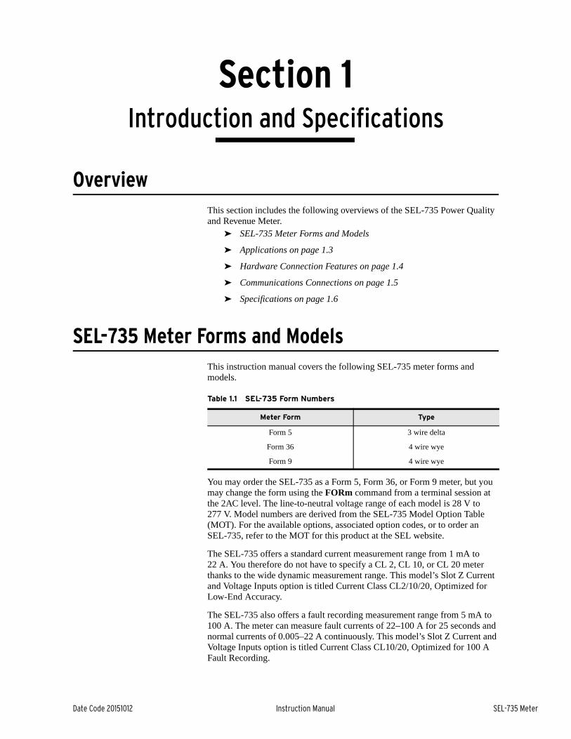
SEL-735 Meter Forms and ModelsThis instruction manual covers the following SEL-735 meter forms and models.
You may order the SEL-735 as a Form 5, Form 36, or Form 9 meter, but you may change the form using the FORm command from a terminal session at the 2AC level. The line-to-neutral voltage range of each model is 28 V to 277 V. Model numbers are derived from the SEL-735 Model Option Table (MOT). For the available options, associated option codes, or to order an SEL-735, refer to the MOT for this product at the SEL website.
The SEL-735 offers a standard current measurement range from 1 mA to 22 A. You therefore do not have to specify a CL 2, CL 10, or CL 20 meter thanks to the wide dynamic measurement range. This model’s Slot Z Current and Voltage Inputs option is titled Current Class CL2/10/20, Optimized for Low-End Accuracy.
The SEL-735 also offers a fault recording measurement range from 5 mA to 100 A. The meter can measure fault currents of 22–100 A for 25 seconds and normal currents of 0.005–22 A continuously. This model’s Slot Z Current and Voltage Inputs option is titled Current Class CL10/20, Optimized for 100 A Fault Recording.
Table 1.1 SEL-735 Form Numbers
Meter Form Type
Form 5 3 wire delta
Form 36 4 wire wye
Form 9 4 wire wye

1.2
SEL-735 Meter Instruction Manual Date Code 20151012
Introduction and SpecificationsSEL-735 Meter Forms and Models
The SEL-735 is available with three different power quality and recording options. Table 1.2 and Table 1.3 list the options.
Table 1.2 SEL-735 Compliance With IEC 61000-4-30 Power Quality Standard A and S refer to IEC 61000-4-30:2008 Class A and Class S compliance, respectively
IEC 61000-4-30 and IEC 61000-4-7 Power QualitySEL-735Basic PQ
SEL-735Intermediate PQ
SEL-735Advanced PQ
Measurement Aggregation Algorithm
Aggregation 10/12 cycle S S S
Aggregation 150/180 cycle, 10 min. – S S
Aggregation 2 hour – A A
Power Quality Parameters
Power frequency A A A
Magnitude of the supply voltage A A A
Flicker – Sa Sa
Supply voltage dips and swells A A A
Voltage interruptions A A A
Supply voltage imbalance A A A
Real-time clock uncertainty A A A
Maximum Harmonic Order 15th 63rd 63rd
Individual voltage harmonics A A A
Individual current harmonics Ib Ib Ib
Power harmonics – – Ib
Voltage interharmonics – – A
Current interharmonics – – Ib, c
a Refers to IEC 61000-4-15:2010 as referenced by IEC 61000-4-30:2008.b Refers to IEC 61000-4-7:2002 Class I compliance.c Meets Class I compliance if nominal current is 2 A or higher and Class II compliance if nominal current is 1 A.
Table 1.3 SEL-735 Waveform Capture Settings Options for Event Reports
Waveform CaptureSEL-735Basic PQ
SEL-735Intermediate PQ
SEL-735Advanced PQ
Samples per cycle 16 16 and 128 16, 128, and 512
Duration (cycles) 15 15, 30, 60, 120, 300, 600 15, 30, 60, 120, 300, 600
Number of Events 64 15–3142 4–3142
COMTRADE Reports Y Y Y

1.3
Date Code 20151012 Instruction Manual SEL-735 Meter
Introduction and SpecificationsApplications
Applications
Figure 1.1 SEL-735 Applied at Billing Points Throughout the Power System
FeederMonitor
AuxiliaryLoads
ProcessLoads
Plant NetInput/Output
EthernetRemoteAccess
RemoteAccess
IndustrialLoad
Power ExchangeMonitoring
Contract BillReconciliation
G
G
Voltage and PowerQuality Monitoring
NET BillingWith Generator Control
Line Loadingand Phase AngleMeasurement
SELCommunications
Processor
G
Unit Output
Local Monitoringand Control
CapacitorControl
Line and TransformerLoss Compensation
SEL-735
SEL-735
SEL-735
SEL-735
SEL-735
SEL-735SEL-735
SEL-735
SEL-735
SEL-735 SEL-735 SEL-735 SEL-735
SEL-735 SEL-735 SEL-735

1.4
SEL-735 Meter Instruction Manual Date Code 20151012
Introduction and SpecificationsHardware Connection Features
Hardware Connection FeaturesSee Specifications on page 1.6 and Section 2: Installation for more information on hardware and connections.
Figure 1.2 SEL-735 Inputs, Outputs, and Communications Ports
CT Board Ia, Ib, Ic
I/O BoardExpansion Slot #24 Digital Inputs4 Digital Outputs (solid-state or electromechanical)
OR4 Analog Outputs4 Solid-State Digital Outputs
Comm BoardExpansion Slot #1EIA-485Telephone ModemEIA-232
Main BoardEthernet,EIA-232,IRIG-B,EIA-485 (Port 3 may be ordered as an EIA-232 port)
Power Supply Board2 Digital Inputs3 Electromechanical
Digital Outputs
PT BoardVa, Vb, Vc, Vn

1.5
Date Code 20151012 Instruction Manual SEL-735 Meter
Introduction and SpecificationsCommunications Connections
Communications ConnectionsSee Port Connector and Communications Cables on page 8.5 for more communications connection information.
Figure 1.3 SEL-735 Communications Connection Examples
ETHERNET CONNECTION
EIA-485 CONNECTIONS
SEL-735Meter(#1)
Computer
Port 4A/Port 3
Port 4A/Port 3
Port 4A/Port 3
SEL Communications Processor
SEL Communications Processor
Port 4C Port 4C
LOCAL CONNECTION
Port 1
(Metallic)CableC273A
Port 3 Port 2
DATA AND TIME-SYNCHRONIZATION CONNECTIONS
SEL-735Meter
MODEM CONNECTION
Port 4B
Connect to the SEL Communications ProcessorOnce and Communicate With Any Connected SEL Meter
Or...Connect to the SEL-735 MetersIndividually Via the Rear-Panel Serial Ports
SEL-735Meter
SEL-735Meter(#32)
SEL-735Meter(#2)
SEL-735Meter
SEL-735Meter
SEL-735Meter
SEL-735Meter
LAN
Cable C234
Fiber-Optic Cable #C800
FZST or #C800
FDST
SEL-2810

1.6
SEL-735 Meter Instruction Manual Date Code 20151012
Introduction and SpecificationsSpecifications
Specifications
ComplianceISO 9001:2008 Certified
ANSI C12.20:2010 Accuracy; class 0.2, CL2, and CL10/CL20 (applies to Blondel-compliant Form 5 and Form 9 only)
ANSI C12.1 (Form 36)
IEC 62053-22:2003; class 0.2 S
IEC 62052-11; rack-mounted meters
IEC 62053-23:2003; class 2 S
C22.2 No. 61010-1-04
CAN/CSA C22.2 No. 142
UL 508
ERCOT Compliant (applies to Blondel-compliant Form 5 and Form 9 only)
CAISO Compliant (applies to Blondel-compliant Form 5 and Form 9 only)
CFG G0000-48-2010 Compliant per LAPEM
NMI M6-1 Electricity Meters: Part 1: Metrological and Technical Requirements
CE: Mark–EMC Directive, Low Voltage Directive
Note: Optional modem not CE compliant.
General
AC Voltage Inputs
Maximum Rating: 300 VL–N, 520 VL–L continuous600 VL–N, 1039 VL–L for 10 seconds
Range:
Revenue: 28–300VL–N, 57–520 VL–L
Measurement: 5–300 VL–N, 9–520 VL–L
Burden: 10 MΩ
AC Current Inputs
Maximum Rating: 22 A continuous500 A for 1 second
Range:
Current Class CL2/CL10/CL20, optimized for low-end accuracy:
Revenue: 0.010–22 A
Measurement: 0.001–22 A continuous
Current Class CL10/CL20, optimized for 100 A fault recording:
Revenue: 0.050–22 A
Measurement: 0.005–22 A continuous22–100 A symmetrical for 25 seconds
Burden: ≤ 0.5 VA
Measurement Category: II
Frequency and Rotation
60 or 50 Hz system frequency specified at time of order. User selectable ABC/ACB phase rotation.
Frequency tracking range: 40 to 70 Hz based on VA or VC.
Power Supply
Continuous Operating Limits
125/250 Volt Supply: 85–264 Vac (50/60 Hz)85–275 Vdc
24/48 Volt Supply: 19–58 Vdc
12/24 Volt Supply: 9.6–30 Vdc
VA Rating: <40 VA/15 W maximum<20 VA/7 W typical
Interruption (IEC 60255-11:1979)
50 ms at 125 Vac/Vdc50 ms at 48 Vdc10 ms at 24 Vdc2 ms at 12 Vdc
Ripple (IEC 60255-11:1979) 12% for dc inputs
Terminal Voltage Dropout:
<40 V within 1 minute of power removal
Rated Insulation Voltage (IEC 60664-1:2002): 300 Vac
Dielectric Test Voltage: 3.1 kVdc
100BASE-FX Fast Ethernet Fiber-Optic Port
Fiber Type: Multimode
Data Rate: 100 Mbps
Wavelength 1300 nm
Optical Connector Type: LC
Link Budget: 11.8 dB
Min. TX Power: –20 dBm
Min. RX Sensitivity: –31.8 dBm
Fiber Size: 62.5/125 μm or 50/125 μm
Approximate Range: 2 km
100BASE-LX10 Fast Ethernet Fiber-Optic Port
Fiber Type: Single-mode
Data Rate: 100 Mbps
Wavelength: 1310 nm
Optical Connector Type: LC
Link Budget: 10 dB
Min. TX Power: –15 dBm
Min. RX Sensitivity: –25 dBm
Fiber Size: 9/125 μm or 8/125 μm
Approximate Range: 10 km
Communications ProtocolsSEL ASCII/Compressed ASCII, SEL Fast Operate/Fast Meter,
MIRRORED BITS, SEL Distributed Port Switch (LMD), Modbus RTU/TCP, DNP3 serial and LAN/WAN, FTP, TCP/IP, SNTP, IEC 61850, Telnet, MV-90, and IEEE C37.118.2
Output Contacts
Ratings determined by IEC 60255-23:1994.
Standard (Electromechanical)
Make: 30 A per IEEE C37.90-19893.6 kVA, Cos φ = 0.3
Break Rating: 360 VA, Cos φ = 0.3
Breaking Capacity (10000 operations):12/24 Vdc 0.75 A L/R = 40 ms48 Vdc 0.50 A L/R = 40 ms125 Vdc 0.30 A L/R = 40 ms250 Vdc 0.20 A L/R = 40 ms

1.7
Date Code 20151012 Instruction Manual SEL-735 Meter
Introduction and SpecificationsSpecifications
Carry: 3 A at 120 Vac, 50/60 Hz1.5 A at 240 Vac, 50/60 Hz50 A for 1 second
Durability: >10,000 cycles at rated conditions
Pickup/Dropout Time: <16 ms
Maximum Operating Voltage (Ue): 250 V
Rated Insulation Voltage (Ui) (excluding EN 61010): 300 V
Optional (Solid State)
Voltage: 250 Vdc or Peak ac maximum
Current: 100 mA maximum
Capacity: 0.6 VA at 25°C, 0.2 VA at 85°C
Pulse Rate: 20 pulses per second
Maximum On Resistance:
Typical: 50 ΩGuaranteed: <100 Ω
Minimum Off Resistance: 10 MΩ
Pickup/Dropout Time: <25 ms
Analog Outputs
Maximum Firmware Update Rate:
100 ms
Maximum Settling Time for Full Range Change to 0.1% Full Scale: 500 ms
Bandwidth: 0 to 4 Hz
±1 mA Output
Range: ±1.2 mA
Minimum Output Impedance: 100 MΩ
Maximum Load: 10 kΩ ,100 μH
Accuracy: ±0.15% ±2.0 μA at 25°C
4–20 mA Output
Range: ±24 mA
Minimum Output Impedance: 100 MΩ
Maximum Load: 500 Ω , 100 μH
Accuracy: ±0.20% ±10 μA at 25°C
Optoisolated Input Ratings
DC Control Signal
250 Vdc: Pickup 200–275 VdcDropout 150 Vdc
220 Vdc: Pickup 176–242 VdcDropout 132 Vdc
125 Vdc: Pickup 100–137.5 VdcDropout 75 Vdc
110 Vdc: Pickup 88–121 VdcDropout 66 Vdc
48 Vdc: Pickup 38.4–52.8 VdcDropout 28.8 Vdc
24 Vdc: Pickup 15–30 VdcDropout <5 Vdc
12 Vdc: Pickup 9.6–16.7 VdcDropout <6 Vdc
AC Control Signal
250 Vac: Pickup 170.6–300 VacDropout 106 Vac
220 Vac: Pickup 150.3–264 VacDropout 93.2 Vac
125 Vac: Pickup 85–150 VacDropout 53 Vac
110 Vac: Pickup 75.1–132 VacDropout 46.6 Vac
48 Vac: Pickup 32.8–57.6 VacDropout 20.3 Vac
24 Vac: Pickup 14–27 VacDropout <5 Vac
Current Draw at Nominal DC Voltage: 2–6 mA
Time-Code Input
Meter accepts demodulated IRIG-B time-code input at EIA-232 Port 3, Port 2, or dedicated IRIG-B port (2-pin Phoenix connector).
IRIG Port Electrical Characteristics
Nominal Voltage: 5 Vdc
Maximum Voltage: 8 Vdc
Input resistance: > 2 kΩ
Dedicated IRIG Port:
On (1) State: Vih ≥ 3.5 V
Off (0) State: Vil ≤ 1.5 V
IRIG pins on Port 2 and Port 3:
On (1) State: Vih ≥ 2.0 V
Off (0) State Vil ≤ 0.8 V
Time Accuracy
Clock Drift with no time input:
4 minutes per year, typical
IRIG Accuracy: ± 2 us
Simple Network Time Protocol (SNTP) Accuracy:
Manycast or Unicast ± 5 ms (when directly connected to SNTP Server)
Broadcast: No specified accuracy
Operating Temperature
IEC 60068-2-2:1993: –40° to + 85°C (–40° to +185°F)
Note: Not applicable to UL applications.
LCD: –20° to +70°C (–4° to +158°F)
Operating Environment
Pollution Degree: 2
Overvoltage Category: II
Indoor Use
Maximum Altitude: 2000 M
Maximum Humidity: 95% RH
Weight
2.3 kg (5.0 lbs)
Dimensions
Refer to Figure 2.1 and Figure 2.2 for meter dimensions.

1.8
SEL-735 Meter Instruction Manual Date Code 20151012
Introduction and SpecificationsSpecifications
Routine Dielectric Test
Current Inputs: 2.75 kVac for 1 s
Voltage Inputs: 2.2 kVac for 1 s
Inputs and Outputs: 2.2 kVac for 1 s
Power Supply: 3.11 kVdc for 1 s
EIA-485 Port: 1.5 kVdc for 1 s
IEC 60255-5:2000Dielectric tests
performed on all units with the CE mark:
2200 Vdc for 1 s on EIA-485 communications port
2000 Vac for 1 s on contact inputs, contact outputs, and analog inputs
Terminal Connections
Rear Screw-Terminal Tightening Torque
Current Input Terminal Block (ring terminals are recommended)
Minimum: 0.9 Nm (8 in-lb)
Maximum: 1.4 Nm (12 in-lb)
Connectorized®
Minimum: 0.5 Nm (4.4 in-lb)
Maximum: 1.0 Nm (8.8 in-lb)
Connectorized terminals accept wire size 12–24 AWG.
User terminals or stranded copper wire should be at a minimum temperature rating of 105°C (221°F).
Synchrophasors
Compliance P Class Synchrophasors compliant with IEEE C37.118.1-2011 as amended by IEEE C37.118.1a-2014.
Data Transfer: IEEE C37.118.2-2011 (Backward compatible with IEEE C37.118-2005)
Message Rates: 60 Hz: 1,2,4,5,10,12,15,20,30,60 messages per second
50 Hz: 1,2,5,10,25,50 messages per second
Nominal Voltage:
120V when VBASE < 180
240V when 180 < VBASE < 250
250V when VBASE >= 250
Voltage Range:
80%–120% of Nominal Voltage
Nominal Current:
5A with CL2/10/20 current card
10A with CL10/20 current card
Current Range:
10% to 200% of Nominal current with CL2/10/20 current card
25% to 200% of Nominal current with CL10/20 current card
Processing Specifications
AC Voltage and Current Inputs
512 samples per power system cycle.
Control Processing
1/2-cycle processing interval
SELOGIC Pickup and Accuracies
SELOGIC Timers: ±1/2 cycle
Analog Values: ±3%
Metering/Monitoring
Metering Accuracy (Form 5 and Form 9 only)
Voltage, Current, Power, and Energy
Unity Power Factor: ± 0.06%± 0.02% typical
0.5 Power Factor: ± 0.16%± 0.06% typical
Frequency:
FREQ_PQ ± 0.001 Hz
FREQ ± 0.05 Hz
Power Quality: IEC 61000-4-30:2008
Flicker
PST: ±5% over the range 0.5–25 PST (10-min. interval)
PLT: ±5% over the range 0.5–25 PLT (2-hour interval)
Type Tests
Electromagnetic Compatibility Immunity
Surge Withstand Capability:
IEC 60255-22-1:2007,Severity Level: 2.5 kV common
mode, 1.0 kV differential mode1.0 kV peak common mode on communications ports
IEEE C37.90.1-2002Severity Level: 2.5 kV oscillatory,
4 kV fast transient
ElectrostaticDischarge Immunity:
IEC 60255-22-2:2008Severity Level: 4 (both polarities at
Levels 1, 2, 3, and 4)IEC 61000-4-2:2008
Severity Level: 4
Radiated Electromagnetic Field Immunity:
IEC 60255-22-3:2007IEC 61000-4-3:2010,Severity Level: 10 V/m
ANSI C12.20-1998,Severity Level: 15 V/m
Electrical Fast Transient Burst Immunity:
IEC 61000-4-4:2011,Severity Level: 4 kV
Surge Immunity: IEC 62052-11:2003,4 kV for Current, Voltage, and Power
Supply Mains1 kV for Auxiliary Circuits
Conducted RadioFrequency Immunity:
IEC 61000-4-6:2008,Severity Level: 10 Vrms
Environmental
Cold: IEC 60068-2-1:2007Test Ad: 16 hours at –40°C
IEEE 1613-2009 + A1-2011
Dry Heat: IEC 60068-2-2:2007,Test Bd: 16 hours at +85°C
IEEE 1613-2009 + A1-2011
Damp Heat, Cyclic: IEC 60068-2-30:2005Test Db: 5% RH, 25° to 55°C,
6 cycles (12 + 12 hour cycle)
Enclosure Protection: IEC 60529:2001, IP65, enclosed in panel with
available gasket (P/N: 915900097); IP41 without gasket; IP20 for rear panel

1.9
Date Code 20151012 Instruction Manual SEL-735 Meter
Introduction and SpecificationsSpecifications
Vibration
Vibration Resistance: IEC 60255-21-1:1988Class 1 Vibration EnduranceClass 2 Vibration Response
Shock Resistance: IEC 60255-21-2:1988Class 1 Shock WithstandClass 2 Shock ResponseClass 1 Bump Withstand
Seismic: IEC 60255-21-3:1993 Class 2 Quake Response
Safety
Dielectric Strength/Impulse:
IEC 60255-5:2000IEEE C37.90:2005IEEE 1613-2009 + A1-2011
Severity Level: 2500 Vac for 1 minute, 3100 Vdc for 1 minute on power supply
Severity Level: 0.5 Joules, 5 kV
High-Voltage Line Surges:
IEEE C62.41-1991100 kHz Ring Wave for Location
Category B3, Peak Voltage of 6 kV and
Short-Circuit Peak Current of 3 kA 1.2/50 μs Combination Wave for Location Category B3,
Peak Voltage of 6 kV and Short-Circuit Peak Current of 3 kA
Rated Impulse Withstand Voltage (Uimp):
IEC 60664-1:20074 kV on power supply, ac current inputs, and voltage inputs

This page intentionally left blank

Date Code 20151012 Instruction Manual SEL-735 Meter
Section 2Installation
OverviewThis section provides instructions and guidelines required to correctly install and check the SEL-735 in the field. SEL recommends that you complete the following steps to install the SEL-735 correctly.
➤ Mount Meter on page 2.2
➤ Make Rear-Panel Connections on page 2.5
➤ Configure and Check Meter Status on page 2.8
Device PlacementPhysical Location
You can mount the SEL-735 in a sheltered indoor environment, a building, or an enclosed cabinet that does not exceed the temperature and humidity ratings for the device. For voltage and current inputs, the SEL-735 is rated for Measurement Category III (LEA inputs are rated for Measurement Category II), and Pollution Degree 2. This rating allows mounting of the meter indoors or in an outdoor enclosure where the meter is protected against exposure to direct sunlight, precipitation, and full wind pressure, but neither temperature nor humidity are controlled. You can place the meter in extreme temperature and humidity locations. The temperature range over which the meter operates is –40° to +80°C (–40° to +176°F). The meter operates in a humidity range from 5 percent to 95 percent, no condensation. The power supply supports voltage fluctuations to as much as ±10 percent of nominal voltage. For IEC 61010 certification, the SEL-735 rating is 2000 meters (6560 feet) above mean sea level.

2.2
SEL-735 Meter Instruction Manual Date Code 20151012
InstallationMount Meter
Mount MeterFigure 2.1, Figure 2.2, and Figure 2.3 give the SEL-735 dimensions for the panel-mount applications.
This section explains how to mount the device in a panel or bracket.
Figure 2.1 SEL-735 Horizontal Panel-Mount Dimensions
Figure 2.2 SEL-735 Vertical Panel-Mount Dimensions

2.3
Date Code 20151012 Instruction Manual SEL-735 Meter
InstallationMount Meter
Figure 2.3 SEL-735 Easily Extractable Meter Panel-Mount Dimensions
Panel-Based or Bracket Mounting
A #3 Phillips® slotted screwdriver with 152.4 mm (6”) shaft is required for panel mounting.
Perform the following steps to safely mount the SEL-735.
Step 1. Ensure that the installation site is ready for the installation.
a. Ensure the site is well lit and free from debris, and ensure that personnel are safe from contact with any energized circuits.
b. Ensure that the panel or bracket cutout is in accordance with the associated dimensions.
c. Ensure there is at least about 152 mm (6”) of clearance behind the panel cutout. The SEL-735 with Connectorized® connectors extends 148.34 mm (5.84”) behind the panel.
Step 2. If you have a gasket for the SEL-735 front panel, place the seal around the device. Ensure that the seal sits flush against the rear edge of the front panel and is not twisted.
Step 3. Insert the SEL-735 into the panel cutout and hold the device flush against the panel.
Step 4. While holding the SEL-735 flush against the panel, screw the four Phillips #3 screws into the rear of the device front panel.
Outdoor Enclosure Mounting
You can order the SEL-735 prewired outdoor enclosure option with mounting hardware for either pole mounting or flush mounting.
Use Figure 2.4 as a guide to installing mounting hardware.NOTE: The outdoor enclosure weighs approximately 14 kg (30 lbs).

2.4
SEL-735 Meter Instruction Manual Date Code 20151012
InstallationMount Meter
Figure 2.4 Outdoor Enclosure Dimensions
Install adequate hardware to secure the enclosure to a solid structure.
Chassis Ground (Earthing)
Ground the meter chassis at the ground terminal located on the rear of the meter.
You must connect the ground terminal labeled GND on the rear of the panel to a rack frame or switchgear ground for safety and performance. Use 10 AWG (6 mm2) to 12 AWG (4 mm2) less than 2 m (6.6 feet) in length for the ground connection.
Figure 2.5 Grounding Terminal Symbol
GND

2.5
Date Code 20151012 Instruction Manual SEL-735 Meter
InstallationMake Rear-Panel Connections
Make Rear-Panel ConnectionsSEL terminals accelerate and simplify connection and disconnection of wiring from the back of the SEL-735.
Figure 2.6 Form 9, 3-Element, Four-Wire Wye Wiring Diagram
Figure 2.7 Form 5, 2-Element, Three-Wire Delta Wiring Diagram
NC
B
LOAD
LINE
A
NCB
A
C
B LOAD
LINE
A
CB
A

2.6
SEL-735 Meter Instruction Manual Date Code 20151012
InstallationMake Rear-Panel Connections
Figure 2.8 Form 36, 2 1/2-Element, Four-Wire Wye Wiring Diagram
Follow these steps to connect Connectorized terminals.
Step 1. Ensure that the conductor size is between 0.25 mm2 (24 AWG) and 4 mm2 (12 AWG).
Step 2. Strip the conductor end to ensure an electrical connection is made.
Step 3. Insert the bare conductor into the connection and past the connection jaw.
Step 4. Tighten the connector to about 0.79 Nm (7 in-lbs) of torque.
Step 5. Complete other wiring connections.
Step 6. Hand-tighten the Connectorized connection mounting screws to the proper terminal on the SEL-735.
Table 2.1 lists the minimum connections necessary for three-phase voltage and current metering.
Table 2.1 Required Rear-Panel Connections (Sheet 1 of 2)
Voltage/Current Input Card
Connection Type
Rear-Panel Connection
Label
Side-Panel Connection
Label
Rear-Panel Connection Input
N/A Chassis Ground GND GND Ground Reference
N/A Power Supply
A01 +/H Positive Voltage Supply
A02 –/N Neutral Voltage Supply
NC
B
LOAD
LINE
A
NCB
A
NOTE: The minimum torque is 0.49 Nm (4.4 in-lbs) and the maximum torque is 0.994 Nm (8.8 in-lbs).

2.7
Date Code 20151012 Instruction Manual SEL-735 Meter
InstallationMake Rear-Panel Connections
Perform the following steps to make the necessary wiring connection to the SEL-735.
Step 1. Ensure that power supply and metering instrument wiring is safe.
Step 2. Route the power supply and metering instrument wiring to the rear of the device.
Step 3. Ensure the power supply voltage source is within the SEL-735 power supply input range, and connect the positive and neutral power supply wires to connections E01 and E02, respectively.
The power supply input range is printed on the side-panel (vertical option) or top-panel (horizontal option) label. Refer to this label for the power supply input range to your SEL-735.
Step 4. Refer to Table 2.1 and Figure 2.6 and connect all necessary rear-panel connections. Ensure that connected circuits conform to the SEL-735 specifications, given in Specifications on page 1.6.
Step 5. Refer to the panel label to connect other necessary rear-panel connections.
Step 6. Ensure that conductors are properly supported, free from hazards, and installed in accordance with local electrical codes.
Step 7. Provide power to the power supply connections you wired in Step 3.
Voltage/Current Transformer
Secondary Current
Measurement
Z01 IA+ Phase A Current (IA) IN
Z02 IA– Phase A Current (IA) OUT
Z03 IB+ Phase B Currenta (IB) IN
Z04 IB– Phase B Currenta (IB) OUT
Z05 IC+ Phase C Current (IC) IN
Z06 IC– Phase C Current (IC) OUT
Secondary Voltage
Measurement
Z07 VA Phase A Voltage (VA)
Z08 VB Phase B Voltagea,b (VB)
Z09 VC Phase C Voltage (VC)
Z10 VN VA, VB, VC Neutral
a For Form 5 metering: Phase B voltage measurement input must be connected to neutral; Phase B current measurement input may be connected but will not be used in measurements.
b For Form 36 metering: Phase B voltage measurement input must be connected to neutral.
Table 2.1 Required Rear-Panel Connections (Sheet 2 of 2)
Voltage/Current Input Card
Connection Type
Rear-Panel Connection
Label
Side-Panel Connection
Label
Rear-Panel Connection Input

2.8
SEL-735 Meter Instruction Manual Date Code 20151012
InstallationConfigure and Check Meter Status
Step 8. View the front-panel LCD of the device. Verify that the front-panel LCD illuminates.
Step 9. Continue to Configure and Check Meter Status.
Configure and Check Meter StatusThis step describes how to check the status and make the necessary initial configuration settings through the front-panel LCD and menu pushbuttons, or any communications port. Please refer to Section 4: ACSELERATOR QuickSet for a complete description of how to perform settings changes.
This step separates into three different substeps based on the interface you use: front-panel interface, port communications, and IRIG-B input; you only need to complete certain steps, depending on the physical interface requirements. The following list explains the recommended installation procedures. Complete each step that pertains to your installation requirements.
➤ Front-panel pushbutton menu. A PC is not required to perform this step.
➤ Front optical port, serial port, or Ethernet communications. Perform this step during meter installations, using a PC to program the device.
➤ IRIG-B port. Carry out this step if an IRIG-B time source is used.
Configure and Check Meter Status Through the Front-Panel Pushbuttons
The front-panel pushbutton interface eliminates the need for a PC to gain access to meter settings. Front-panel pushbuttons provide access to communications settings, general meter settings, and diagnostics. This section explains only essential meter settings configuration.
Please follow these guidelines when navigating the front-panel menu tree.
➤ Front-panel pushbuttons ENT, ESC, UP, DOWN, LEFT, and RIGHT navigate through the front-panel LCD menu tree.
➤ At any time, you can press ESC to exit the active menu.
➤ Appearance of the cursor under a menu item indicates that that menu item is active.
➤ Press ENT to view and configure the active menu structure. A blinking cursor indicates a meter request for a user prompt.
➤ Use the pushbuttons to interact with the LCD text entry display and enter new text strings.
➤ Press and hold the ESC pushbutton to adjust the contrast of the front-panel LCD.
Follow the instructions below to configure the meter identifier, the terminal identifier, and the potential and current transformer ratios through the front-panel pushbuttons.
Step 1. Configure the initial device settings.
a. Press ENT.
The meter displays the top of the menu structure. The menu structure allows for viewing and changing meter measurements and settings.

2.9
Date Code 20151012 Instruction Manual SEL-735 Meter
InstallationConfigure and Check Meter Status
b. Press DOWN to scroll down until Set/Show is active.
c. Press ENT.
The meter displays the top of the setting groups available for configuration and display.
d. Press ENT.
The meter displays the beginning of the front-panel General Settings group. The following Table 2.2 shows a list of essential initial settings available through the front-panel pushbuttons. Note that Table 2.2 lists only those settings necessary for initial installation.
e. Press ENT.
f. Enter the Access Level 2 (2AC) password by following the text entry prompts on the LCD.
The default EAC password is BLONDEL, and the default 2AC password is TAIL.
g. Enter the new MID by following the text entry prompts on the LCD.
The MID is a user-defined text string that is available to the communication protocols. For example, Itron MV-90 communications read the MID or TID strings as one step toward validating the meter.
h. Repeat Step g, except scroll down further to enter new terminal identifier, potential and current transformer ratios, and any other necessary settings.
i. Press ESC to escape the menu item until the LCD prompts SAVE SETTINGS (Y/N)?
j. Enter Y to indicate Yes and press ENT.
k. Press ESC to exit the menu.
Step 2. Check the measured voltage quantities.
a. Press ENT, and then activate MAIN > Meter > Voltage.
The meter displays the rms voltage quantities and their scaling.
b. Ensure the measured quantities are correct.
Optionally, repeat Step a and Step b, but check the rms current quantities from the menu item MAIN > Meter > Current.
Table 2.2 Essential Initial Settings
Setting Name Description Default Setting Range
MID Meter Identifier FEEDER 1 String
TID Terminal Identifier STATION A String
CTR Current Transformer Ratio 1.0000 1.0000–6000.0000
PTR Potential Transformer Ratio
1.0000 1.0000–6000.0000
VOLT_SCA Voltage Scaling KILO UNITY, KILO, MEGA
POWR_SCA Power Scaling KILO UNITY, KILO, MEGA
ENRG_SCA Energy Scaling KILO UNITY, KILO, MEGA
PRI_SCA Analog Quantity Scaling Y Y, N
NOTE: Instrument ratios have either 1 V or 1 A base.

2.10
SEL-735 Meter Instruction Manual Date Code 20151012
InstallationConfigure and Check Meter Status
c. Press ENT, and then activate MAIN > Status.
d. Press DOWN to scroll down and view the following diagnostic points.
Device Status (STATUS)Firmware Identifier (FID)Part Number (PARTNO)Power Supply Status (Batt, Temp)
e. Record the FID string of the device for use in subsequent steps.
Configure and Check Meter Status Through the Front Port, Serial Port, or Ethernet Port
The front port, serial ports, and Ethernet ports of the SEL-735 allow fast communications through a secure communications channel from your PC to the SEL-735. Once you have established a communications link, you can use ACSELERATOR QuickSet® SEL-5030 Software to configure the meter. Refer to Section 4: ACSELERATOR QuickSet for complete details of the features of the software.
For connection to a communications port, complete the following steps.
Step 1. Connect the communications cable from your PC to the SEL-735.
a. For front optical communications, connect the optical probe from your PC to the SEL-735 front optical port.
Ensure that you have installed drivers properly for the type of optical probe you will be using.
The following list shows the known compatible optical probes of the SEL-735.
Abacus Electris A9U, USB (Requires additional software
drivers)
Abacus Electris A7Z
Abacus Electris A6Z
ABB Unicom III
GE SmartCoupler SC-1A
Microtex Electronics FR3 (Requires additional software
drivers)
P+E Technik K01-USB (Requires additional software drivers)
uData Net PM500-300
b. For serial communications, connect an SEL-C234, SEL-C272, SEL-C287, or equivalent cable from your PC’s DB-9 serial port to any SEL-735 EIA-232 serial port.
Table 2.3 shows the pin functions of serial ports.
Table 2.3 Serial Port Pin Function (Sheet 1 of 2)
EIA-232 Port Pin Number Pin Function
1 +5 VDCa
2 RXD
3 TXD
4 +IRIG-Ba
5 GND
6 –IRIG-Ba
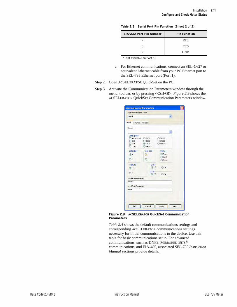
2.11
Date Code 20151012 Instruction Manual SEL-735 Meter
InstallationConfigure and Check Meter Status
c. For Ethernet communications, connect an SEL-C627 or equivalent Ethernet cable from your PC Ethernet port to the SEL-735 Ethernet port (Port 1).
Step 2. Open ACSELERATOR QuickSet on the PC.
Step 3. Activate the Communication Parameters window through the menu, toolbar, or by pressing <Ctrl+R>. Figure 2.9 shows the ACSELERATOR QuickSet Communication Parameters window.
Figure 2.9 ACSELERATOR QuickSet Communication Parameters
Table 2.4 shows the default communications settings and corresponding ACSELERATOR communications settings necessary for initial communications to the device. Use this table for basic communications setup. For advanced communications, such as DNP3, MIRRORED BITS® communications, and EIA-485, associated SEL-735 Instruction Manual sections provide details.
7 RTS
8 CTS
9 GND
a Not available on Port F.
Table 2.3 Serial Port Pin Function (Sheet 2 of 2)
EIA-232 Port Pin Number Pin Function
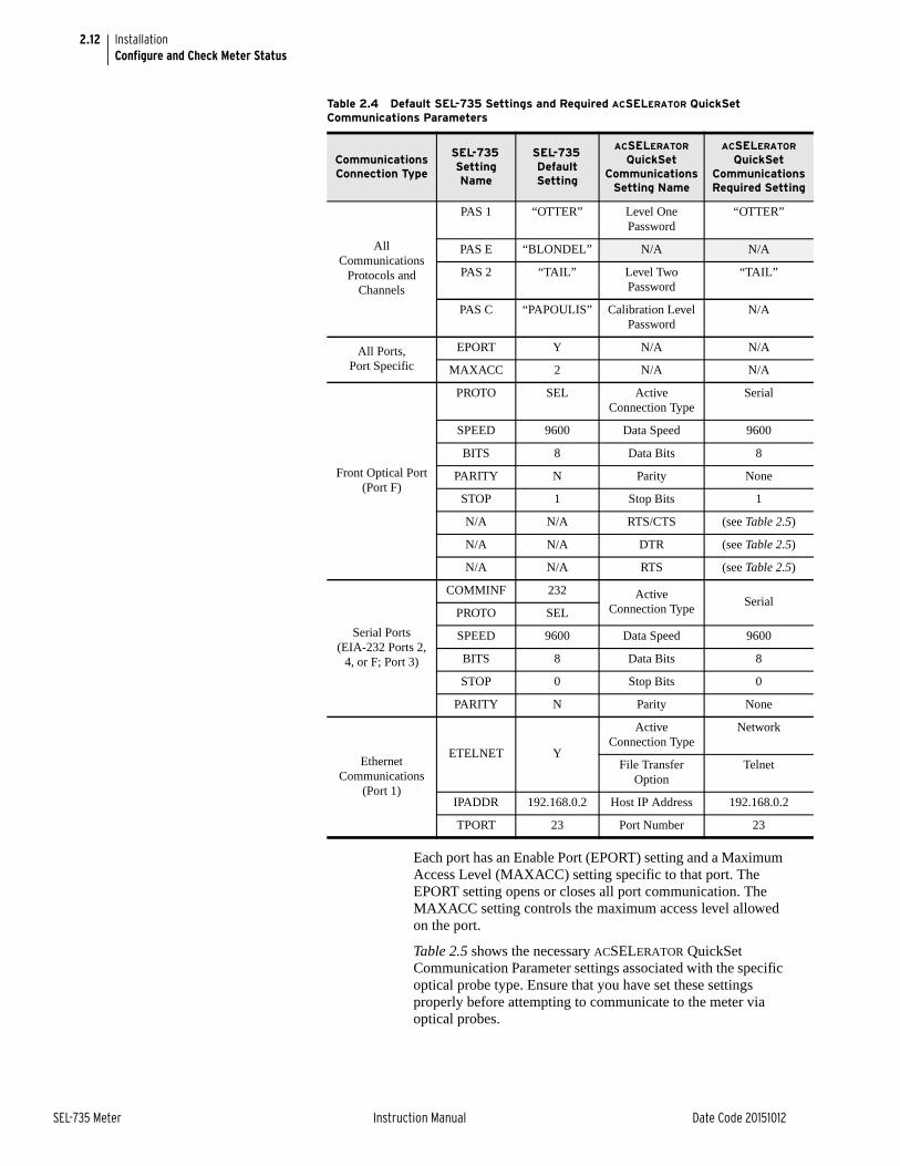
2.12
SEL-735 Meter Instruction Manual Date Code 20151012
InstallationConfigure and Check Meter Status
Each port has an Enable Port (EPORT) setting and a Maximum Access Level (MAXACC) setting specific to that port. The EPORT setting opens or closes all port communication. The MAXACC setting controls the maximum access level allowed on the port.
Table 2.5 shows the necessary ACSELERATOR QuickSet Communication Parameter settings associated with the specific optical probe type. Ensure that you have set these settings properly before attempting to communicate to the meter via optical probes.
Table 2.4 Default SEL-735 Settings and Required ACSELERATOR QuickSet Communications Parameters
Communications Connection Type
SEL-735 Setting Name
SEL-735 Default Setting
ACSELERATOR QuickSet
Communications Setting Name
ACSELERATOR QuickSet
Communications Required Setting
All Communications
Protocols and Channels
PAS 1 “OTTER” Level One Password
“OTTER”
PAS E “BLONDEL” N/A N/A
PAS 2 “TAIL” Level Two Password
“TAIL”
PAS C “PAPOULIS” Calibration Level Password
N/A
All Ports, Port Specific
EPORT Y N/A N/A
MAXACC 2 N/A N/A
Front Optical Port (Port F)
PROTO SEL Active Connection Type
Serial
SPEED 9600 Data Speed 9600
BITS 8 Data Bits 8
PARITY N Parity None
STOP 1 Stop Bits 1
N/A N/A RTS/CTS (see Table 2.5)
N/A N/A DTR (see Table 2.5)
N/A N/A RTS (see Table 2.5)
Serial Ports (EIA-232 Ports 2,
4, or F; Port 3)
COMMINF 232 Active Connection Type
SerialPROTO SEL
SPEED 9600 Data Speed 9600
BITS 8 Data Bits 8
STOP 0 Stop Bits 0
PARITY N Parity None
EthernetCommunications
(Port 1)
ETELNET Y
Active Connection Type
Network
File Transfer Option
Telnet
IPADDR 192.168.0.2 Host IP Address 192.168.0.2
TPORT 23 Port Number 23

2.13
Date Code 20151012 Instruction Manual SEL-735 Meter
InstallationConfigure and Check Meter Status
Step 4. Enter the proper ACSELERATOR QuickSet Communication Parameters that correspond to the communications link you have chosen, shown in Table 2.4 and Table 2.5.
Step 5. Click Apply.
Step 6. Verify that the TXD and RXD indicators flash green and red, indicating transmitted and received communication activity, respectively. These are located in the lower left-hand corner of ACSELERATOR QuickSet, as shown in Figure 2.10.
Step 7. Verify that the connection status indicates Connected, also shown in Figure 2.10.
The Transmit and Receive indicators only illuminate during communications activity. The connection status shows whether the link is connected or disconnected. The connection details show the communications settings. The terminal protocol shows the protocol that terminal sessions use. Finally, the file transfer protocol shows the protocol of file transfer communications.
Figure 2.10 ACSELERATOR QuickSet Communications Activity and Status
If the communications fail to connect, please verify operation of the applicable port communications through the front-panel pushbuttons.
Step 8. Click OK.
ACSELERATOR QuickSet is now connected to the SEL-735, and you can use this interface to configure device settings and access all meter data.
Table 2.5 Optical Probe Required Communications Settings
Optical Probe Type
ACSELERATOR QuickSet
Communications Setting Name
ACSELERATOR QuickSet
Communications Required Setting
Abacus Electris A9U, USB (SEL part #C661)
RTS/CTS Off
DTR Off
RTS On
Abacus Electris A7Z, ABB Unicom III, GE SmartCoupler SC-1A
DTR Off
Microtex Electronics FR3 Data Speed 19200 or slower
Transmit andReceiveActivity
Connection Status
ConnectionDetails
Terminal Protocol
File Transfer Protocol

2.14
SEL-735 Meter Instruction Manual Date Code 20151012
InstallationConfigure and Check Meter Status
Step 9. Complete either Step 9a or Step 9b to create a new settings file.
a. Create New Settings.
When you create new settings from ACSELERATOR QuickSet, all default settings load into the new device Settings Editor instance. ACSELERATOR QuickSet displays an interactive part number selector, so you can easily choose the correct part number of your SEL-735 Settings Editor instance. By default, ACSELERATOR QuickSet hides the advanced and nonapplicable settings in the new Settings Editor.
i. Click File > New (or Ctrl+N).
ii. Select the correct part number for your device.
iii. Click OK.
Figure 2.11 shows the default options for the SEL-735.
Figure 2.11 SEL-735 Model Option Table
b. Read Settings.
The following steps and ACSELERATOR QuickSet menu/toolbar diagrams show how to read device settings from the SEL-735 and the reading process behavior. SEL recommends you read and save settings before and after each settings change.
i. Click File > Read (or Alt+F+R).
ii. Click OK.
ACSELERATOR QuickSet reads the settings from the SEL-735, and populates the settings into a new Settings Editor instance. Any settings groups that ACSELERATOR

2.15
Date Code 20151012 Instruction Manual SEL-735 Meter
InstallationConfigure and Check Meter Status
QuickSet did not read will open with default values in the Settings Editor. You can then compare old and new settings with each other, and you can have ACSELERATOR QuickSet produce a settings change report. To compare settings, select Edit > Compare.
Step 10. Save Settings
The following steps and ACSELERATOR QuickSet menu/toolbar diagrams show how to save device settings to your PC.
a. Click File > Save (or Ctrl+S).
b. Type a new settings name to save the active settings as a new settings file, or select a previously saved settings file to save over the selected file.
c. Click OK, or press <Enter>.
ACSELERATOR QuickSet saves the active device settings in the Active Database. The default database is normally stored as C:\Program Files\SEL\acSELerator\Quickset\Relay.rdb, but you can also use other databases. Please refer to the Database Manager instructions. You can then compare old and new settings with each other, and have ACSELERATOR QuickSet produce a settings change report. To compare settings, select Edit > Compare.
Step 11. Configure Identifier and Scaling Settings
The Identifier and Scaling settings are essential for proper metering operations. These settings define the identifier of your device, the instrument transformer ratios, and the scaling the meter applies to external interfaces. Figure 2.12 shows the default Identifier and Scaling settings.
a. Enter the new meter identifier (MID). This is a user- defined text string that is available to communication channels. Allowed characters are A–Z, 0–9, /, and –.
b. Enter the current transformer ratio (CTR) and the potential transformer ratio (PTR).
Figure 2.12 Identifier and Scaling Settings

2.16
SEL-735 Meter Instruction Manual Date Code 20151012
InstallationConfigure and Check Meter Status
c. Enter the scale factor for voltage (VOLT_SCA), power (POWR_SCA), and energy (ENRG_SCA) values that the meter applies to the respective analog quantity on all external interfaces (unless called out otherwise in Analog Quantity Scaling on page G.2). You can also use one of the 1000 available configurable registers to perform custom scaling and formatting of analog quantities.
d. Configure scale factors (PRI_SCA) to scale all analog quantities in either primary or secondary units. The scale factor applies to all external interfaces (unless called out otherwise in Analog Quantity Scaling on page G.2).
Step 12. Send Settings
The following steps and ACSELERATOR QuickSet menu/toolbar diagrams explain how to send active device settings to the SEL-735 and the writing process behavior. SEL recommends that you save settings with a unique name before sending them.
a. Click Send.
The Settings Group/Class Select window opens as shown in Figure 2.13. ACSELERATOR QuickSet automatically selects any setting groups that have changed since the last read.
Figure 2.13 Settings Group/Class Select to Send Window
b. Select or deselect the appropriate group settings.
c. Click OK.
ACSELERATOR QuickSet sends the selected groups to the device.

Date Code 20151012 Instruction Manual SEL-735 Meter
Section 3Front-Panel Operation
OverviewThis section details the physical operations of the device and contains details necessary for front-panel LCD communication. The front-panel display provides access to many menus and meter features, which this section describes.
The Section 9: Testing and Troubleshooting contains information on TEST mode access, communications, operations, and recommended practices.
Configurable Registers are variables to which you can assign metered quantities and communicate results through various channels, including the front-panel LCD. Custom formatting and scaling aid in understanding the information. Please see Section 5: Metering for Configurable Register details.
Sixteen custom front-panel displays, known as display points, are also very useful tools for quick access to information and interfacing with the device.
Access LevelsOverview The SEL-735 has three normal access levels: Access Level 1 (ACC), Access
Level E (EAC), and Access Level 2 (2AC). From these three access levels, you can fully configure and operate the meter. You can gain access to the access levels through certain communications protocols. For example, you can write to some registers via DNP and Modbus® only after gaining EAC access through the same communications channel. The meter also allows you to configure different maximum levels of access for each communications port.
ACCFrom this level, you can only view meter settings and quantities. This is the front-panel LCD default access level mode. Please ensure that only those allowed to view meter settings and quantities can access the front panel.
EACFrom this level you can set the date; set the date and time; and clear load profile recorders, crest factor metering, maximum/minimum metering, and peak demand metering.
2ACFrom this level, you can configure all settings and control functions of the SEL-735. Please see Section 4: ACSELERATOR QuickSet for details on configuration settings and control functions.

3.2
SEL-735 Meter Instruction Manual Date Code 20151012
Front-Panel OperationFront-Panel Operations
Access Level CThe CAL access level is intended for use by the SEL factory, and for use by SEL field service personnel to help diagnose troublesome installations. A list of commands available at the CAL level is available from SEL upon request. Do not enter the CAL access level except as directed by SEL.
The CAL command allows the meter to go to Access Level C. Enter the CAL command at the Access Level 2 prompt.
SEL CommunicationsSEL protocols confirm the password for each new SEL communications channel instance. Access to each communications channel session times out after three minutes of inactivity or when the port times out, whichever is shorter.
Port SecurityYou can configure each port to allow a maximum access of ACC, EAC, or 2AC or to turn the port completely off to any communications. Please see Section 4: ACSELERATOR QuickSet for more details on port security.
Front-Panel OperationsLayout The SEL-735 front-panel interface consists of six programmable LEDs, an
LCD display, a menu keypad, a TEST LED, an optical or EIA-232 communications port, and four control pushbuttons.
Figure 3.1 shows the front-panel layout of the SEL-735 horizontal unit, and Figure 3.2 shows the vertical unit.
Figure 3.1 SEL-735 Horizontal Unit Front-Panel Layout
LCD Display
Front Communications Port
Meter ENABLED LED
User-ConfigurableRESET Pushbutton
Six Programmable LEDs
Menu Keypad
Test LED
FOUR CONTROL BUTTONS
TESTMODE
DISPLAY
WAVEFORM
RESET

3.3
Date Code 20151012 Instruction Manual SEL-735 Meter
Front-Panel OperationFront-Panel Operations
Figure 3.2 SEL-735 Vertical Unit Front-Panel Layout
The following list gives a brief explanation of each of the previously shown front-panel functions.
Six Programmable LEDsControl the front-panel LED states via SELOGIC control equations. By default, three LEDs show the undervoltage status of each phase.
LCD DisplayUse the front-panel LCD to view metered quantities, view diagnostics, configure meter settings, reset metered quantities, and enter TEST mode. You can configure different display points for Normal and Alternate modes.
Menu KeypadUse the menu keypad in conjunction with the LCD to navigate menus. With the Menu keypad, you can access metering data, reset certain quantities, and configure meter settings. Please see Section 2: Installation and the SEL-735 Quick-Start Guide for more information.
TEST LEDThe TEST LED outputs infrared light pulses that follow the state of the KYZ test pulses. The TEST LED is only active when the meter is in TEST mode.
Front Communications PortThe device can be ordered with either an ANSI Type 2 Optical or an EIA-232 serial front port. Use this port for easy front-panel serial communications. The optical communications port outputs test pulses when the meter is in TEST mode.
LCD Display
Meter ENABLED LED
User-ConfigurableRESET Pushbutton
Six Programmable LEDs
Menu Keypad
Test LED
FOUR CONTROL BUTTONS
TESTMODE
DISPLAY
WAVEFORM
RESET
Front Communications Port

3.4
SEL-735 Meter Instruction Manual Date Code 20151012
Front-Panel OperationFront-Panel Operations
Four Control PushbuttonsThe meter performs default functions when the control Pushbutton Default Function (PBDFLT) setting is set to Yes and you press any of the four control pushbuttons. The following list summarizes the default functions of each button.
TEST MODEPress this button to quickly enter TEST mode through the front-panel LCD (you must enter a valid 2AC level password). The LEDs next to the control button replicate the state of the KYZ test pulses.
DISPLAYPress this button to toggle between normal and alternate displays. The LEDs next to the control button show the present display mode state.
WAVEFORMPress this button to trigger an event and capture a waveform. The LED next to the control button shows the status of the waveform capture.
RESETPress this button to reset the latched power quality alarm. The LED next to the control button shows the state of the power quality alarm.
Custom Pushbutton Control
Set the Pushbutton Default Function setting to N to program these four pushbuttons and their associated LEDs with custom control equations to perform different tasks. For example, program a pushbutton to reset a remote lockout protection function after you depress the pushbutton for a length of time. The following Figure 3.3 shows an example logic diagram to perform this function. The SELOGIC Variable 01 pickup timer (SV01 and titled Pushbutton Delay Timer) does not assert output SV01T until PB01 is held for at least 5 seconds. A rising edge from the output of this timer while SELOGIC Latch 01 is asserted resets the lockout condition. SELOGIC Variable 02 pickup timer ensures the lockout condition has been asserted for at least 30 seconds before it resets. This minimizes the chance of hunting or race conditions from occurring.
Figure 3.3 Graphical Logic Editor Lockout Latch Control Example
Figure 3.4 shows the Compile tool window in the graphical ACSELERATOR QuickSet® SEL-5030 Software Logic Editor. The settings highlighted in yellow indicate that the present device setting differs from the new setting the logic editor derived. Click the Apply to Settings button to apply the new settings shown to the active settings.
LT01
SV02
SV01
PUSHBUTTON DELAY TIMER
SET LOCKOUT (RB01)
SET LOCKOUT (OUT101)
Var Tmr
PU TDO
Latch
RS Q
RTrig
RTrig
And
RESET LOCKOUT (PB01)50
300
Var Tmr
PU TDO

3.5
Date Code 20151012 Instruction Manual SEL-735 Meter
Front-Panel OperationNormal Operation
Figure 3.4 Graphical Logic Editor Compile Logic Window
Normal OperationIn normal operation, the meter ENABLED LED illuminates and the LCD display screen displays the programmed display points. The LCD screen normally rotates display of display points, showing each for about six seconds before moving to the next.
Figure 3.5 Default Light Illuminated
In any front-panel access level, the device automatically times out after three minutes of inactivity. The LCD illumination turns off, but the active menu item remains selected.
Certain diagnostics results write messages to the front-panel LCD. For a list of the diagnostic messages shown on the LCD, please see Section 9: Testing and Troubleshooting.
The SEL-735 settings T01_LED–T14_LED control the 14 front-panel LEDs. You can set these settings through use of SELOGIC control equations available in the front-panel LED logic settings and cited in Section 4: ACSELERATOR QuickSet.
LCD Automatic MessagesUnder normal conditions, the SEL-735 displays the programmed display points based on the display point logic expressions. If a diagnostics error occurs, the meter displays a message and turns off the ENABLE light. For complete details on error messages, please see Section 9: Testing and Troubleshooting. If this or any abnormality with the device occurs, please contact SEL.
Compile Logic toText or Settings
Settings: RST01Group: LNew Value: R_TRIG SV01T and SV02TOld Value: NA
735Meter

3.6
SEL-735 Meter Instruction Manual Date Code 20151012
Front-Panel OperationMenus and Operations
Menus and OperationsThe SEL-735 front panel provides you access to most meter information.
The meter front panel typically operates at Access Level 1 and allows any user to view meter measurements and settings. Some activities, such as editing settings, are restricted to operators with Access Level 2 privileges.
Use the seven-button keypad and LCD display to access meter information and settings. Use the keypad to maneuver within the front-panel menu structure, described in detail throughout the remainder of this section. Table 3.1 describes the function of each front-panel pushbutton.
Please follow these guidelines when navigating the front-panel menu tree.
➤ The front-panel pushbuttons ENT, ESC, UP, DOWN, LEFT, and RIGHT navigate through the front-panel LCD menu tree.
➤ At any time, press ESC to exit the active menu.
➤ A blinking-cursor under menu items indicates that the menu item is active.
➤ Press ENT to view and configure the active menu structure.
➤ A blinking cursor indicates the need for a user prompt.
➤ Use the pushbuttons to enter new text strings by interaction of the LCD text entry display, as shown in Figure 3.6.
➤ Hold the ESC pushbutton to adjust the contrast of the front-panel LCD.
Table 3.1 Front-Panel Pushbutton Functions
Pushbutton Function
UP ARROW Move up within a menu or data list.
While editing a setting value, increase the value of the underlined digit.
DOWN ARROW Move down within a menu or data list.
While editing a setting value, decrease the value of the underlined digit.
LEFT ARROW Move the cursor to the left.
While viewing Event Data, move to data for a newer event.
RIGHT ARROW Move the cursor to the right.
While viewing Event Data, move to the data for an older event.
ESC Wake up the front-panel display.
Escape from the current menu or display.
Hold to adjust the contrast.
ENT Wake up the front-panel display.
Move from the default display to the main menu.
Select the menu item at the cursor.
Select the displayed setting to edit the setting.
RESET Test front-panel LEDs, reset the timer when in TEST mode, and assert the RESET bit.

3.7
Date Code 20151012 Instruction Manual SEL-735 Meter
Front-Panel OperationMenus and Operations
Figure 3.6 Keypad Entry Through Front-Panel LCD
Main Menu All access to information and meter settings through the front panel starts at the meter Main Menu.
Table 3.2 shows the menus and submenus available via the front panel.
When you change any settings, the SEL-735 prompts you with the message Save Changes to Settings? before it saves any settings.
2AC
SET PASSWORDEAC Password2AC Password
Select Access Level to Change Password Function
New EAC Pwd=Del Clr AcceptA B C D E F G H I JK L M N O P Q R S TU V W X Y Z . . . . a b c d e f g h i jk l m n o p q r s tu v w x y z . . . .1 2 3 4 5 6 7 8 9 0! " # $ % ^ ' ( ) *+ , - . / : ; < = >? @ [ \ ] ^ _ ` { |} ~ . . . . . . . .
Press these keysto move between rows.
Press this key to select a character.
Press these keys to move between Del, Clr, Accept, and row characters.Del: Delete character(s)Clr: Clear passwordAccept: Accept password/character(s)
Table 3.2 SEL-735 Front-Panel Menu Structure (Sheet 1 of 2)
Menu Option Function
Meter Voltage Display Voltages
Current Display Currents
Power Display Powers
Max/Min Display Max/Min Display Max/Min Values and the Date/Time of Last Max/Min Reset, and Reset Max/Min Values
Last Max/Min Reset
Reset Max/Mina
Energy Display Energy Display Energy Values and the Date/Time of Last Energy Reset, and Reset Energy Values
Last Energy Reset
Reset Energya
Demand/Peak Display Demand Reset Display Demand Values and the Date/Time of Last Demand Reset, Display Peak and Previous Peak Values and the Date/Time of Last Peak Reset, Display Number of Peak Demand Resets, Reset Demand or Peak Demand
Display Peak
Last Peak Reset
Previous Peak
Resets
Reset Demanda
Reset Peakb
Harmonics Display THD, K-Factor, and Distortion Power

3.8
SEL-735 Meter Instruction Manual Date Code 20151012
Front-Panel OperationDisplay Points
Passwords via Front Panel
Before you can perform a front-panel menu activity that is marked in the instruction manual with the necessary access level, you must enter the correct Access Level 2 (2AC) password or Access Level E (EAC) password. After you have correctly entered the password, you can perform other activities at equal and lower access levels without having to reenter the password. You can only configure display points through communications channels other than the front panel.
Display PointsYou can customize the LCD through the use of 16 different display points, which can display both analog and binary data in customized messages and formats. For easier and more flexible display configurations, you may use Configurable Registers in Display Points. The meter can display 20 small-font characters on a single line and 9 large-font characters on a single line. If the number of characters exceeds the length of the LCD viewing area, the line scrolls to show all of the text.
If the display point is set to display binary data, then the point can have two text strings: one set text string and one clear text string. Either the set or clear text string displays when the associated binary point is either set or clear, respectively. You can use any Device Word bit as the binary display point.
If the display point is set to display analog data, then you can change the scaling and choose to view quantities in primary or secondary values.
Events Display Events Display Events
Reset Eventsa Reset Events
Targets Display Device Word Bits
Status Display Device Status, FID, Part Number, Power Supply Status, Battery Voltage, and Operating Temperature.
Set/Show General Settingsa Set or Show Identifier and Scaling, Global, Demand, Loss Compensation, KYZ Pulse Outputs, and Fast Messages Settings
Port Settingsa Set or Show Front Port, Port 1, Port 2, Port 3, or Port 4 Settings
Front-Panel Settingsa Set or Show Display Points Settings
Date/Timeb Set or Show the Date and Time
Set Password Set EACb and 2ACa Passwords
Resetc Reset Device
TEST Modea Select Test Quantity Select the Energy Analog Quantity for testing
Watthour Constant Adjust the pulse constant for the test
Compensation Setting Toggle Transformer and Line Loss Compensation On or Off for the test
Gain Settings Adjust Watt and VAR Gain
a 2AC access required to reset quantity or change setting.b EAC access required to reset quantity or change setting.c Only displays if the meter is disabled.
Table 3.2 SEL-735 Front-Panel Menu Structure (Sheet 2 of 2)
Menu Option Function

3.9
Date Code 20151012 Instruction Manual SEL-735 Meter
Front-Panel OperationDisplay Points
By default, the front-panel LCD displays each display point for six seconds before displaying the next point. Adjust the Display Update Rate setting (SCROLD) to change the length of time each point displays.
SELOGIC display point control equations DPnn (nn = 01–16) control the display status of each corresponding text string DPnn_0 and DPnn_1. For example, the following settings demonstrate how display points function when the Device Word bit ALTMODE asserts and deasserts.
DP01 := ALTMODE
DP01_1 := “ALTERNATE MODE”
DP01_0 := “Normal Mode”
The SELOGIC control equation DP01 is True (asserted) when the Device Word bit ALTMODE asserts. When DP01 is True the device displays ALTERNATE MODE on the LCD, and when DP01 is False the device displays Normal Mode.
Default Display The device comes with default display point settings for normal and alternate displays. The front-panel control pushbutton PB02 toggles (by default) between normal and alternate displays. The device reverts back to the normal display after the Front-Panel Timeout, FP_TO, expires without any front-panel activity.
Table 3.3 lists the default display points for the normal and alternate display modes.
Table 3.3 Default Normal and Alternate Display Points (Sheet 1 of 2)
Normal Display Points Alternate Display Points
Analog Quantity Description Analog Quantity Description
WH3_DEL Watt-hours Delivered CWH3_DEL Consumed Watt-hours Delivered in the pres-
ent month
WH3_REC Watt-hours Received CWH3_REC Consumed Watt-hours Received in the previ-
ous month
QH3_DEL VAR-hours Delivered PRES_W_1_PD Peak Demand Watts of the present season
QH3_REC VAR-hours Received CWH3_DEL_1M Consumed Watt-hours Delivered in the previ-
ous month
PFT3 True Power Factor CWH3_REC_1M Consumed Watt-hours Received in the previ-
ous month
WP3_DEL Peak Watts Delivered PREV_W_1_PD Peak Demand Watts of the previous season
WP3_REC Peak Watts Received
QP3_DEL Peak VARs Delivered
QP3_REC Peak VARs Received
IA Phase A RMS Current
IB Phase B RMS Current
IC Phase C RMS Current
VA Phase A RMS Voltage

3.10
SEL-735 Meter Instruction Manual Date Code 20151012
Front-Panel OperationDisplay Points
See Display Point Builder on page 4.6 for information on how to configure display points through an intuitive interface.
Customize Strings Each display point setting contains one or more of the following: Analog Quantity, Device Word bit, user-defined text, and/or user-defined numerical formatting. Device Word bits and analog quantities are displayed as default form or as user-defined text.
Display point setting strings have a maximum length of 64 characters. Quotes are optional and are required only if the given string contains commas or spaces. If the entire string is empty the meter does not display it. Table 3.4 shows the elements of display point string settings.
The following text shows the correct format of display point string elements. The meter displays an error message if you configure it with an incorrect format.
Name—Displays the given entry exactly as seen on the setting line (name, value, and units). Name is any valid analog quantity or a Device Word bit. See Section 8: Communications and Appendix G: Analog Quantities and Device Word Bits for valid display point names.
Name, “Alias”—Display given entry, replacing Name with the given Alias string.
Name, “Alias”, “Set String”, “Clear String”—This format requires that Name be a Device Word bit. Display the given entry as Alias. If the Device Word bit state is asserted (logical 1), display the Set String as the value. If the Device Word bit state is deasserted (logical 0), display the Clear String as the value. Alias, Set String, or Clear String can be empty. If Alias is empty, then only the Set String or Clear String will be displayed. If either Set String or Clear String is empty, then the item will not be visible when the bit matches that state. If an empty line is necessary in this case (instead of hiding the line), then you should use empty curly braces ({}) for the Set String or Clear String. Alias and Set String/Clear String are all displayed on the same line of the front-panel display.
VB Phase B RMS Voltage
VC Phase C RMS Voltage
Table 3.3 Default Normal and Alternate Display Points (Sheet 2 of 2)
Normal Display Points Alternate Display Points
Analog Quantity Description Analog Quantity Description
Table 3.4 Display Point Setting Definitions
Term Definition
Name Any valid Analog Quantity or Device Word bit you want to display
Alias An alternate name (string) displayed, replacing the Analog Quantity or Device Word bit assigned in Name
Set String A user-defined string displayed when the Device Word bit assigned in Name asserts (logical 1)
Clear String A user-defined string displayed when the Device Word bit assigned in Name deasserts (logical 0)
User text {numerical formatting}
A user-defined text string (Alias) replacing the {numerical formatting} with {width.dec,scale} where the value of Name is scaled by “scale,” formatted with total width “width” and “dec” decimal places. Maximum width and dec total 20 digits.

3.11
Date Code 20151012 Instruction Manual SEL-735 Meter
Front-Panel OperationDisplay Points
Name, “User text {numerical formatting}”—Display given entry, replacing Name with User text and displaying the value of Name in the user-defined format {width.dec,scale}, {numerical formatting}. The value is scaled by “scale,” formatted with a total digit width “width” and “dec” decimal places as defined in {numerical formatting} ({width.dec,scale}). Name can be either an analog quantity or a Device Word bit. The width value should include the decimal point and sign character, if applicable. The “scale value” is 1 if omitted. If the numeric value is smaller than the field size you requested, the SEL-735 pads fields with spaces to the left of the number. If the numeric value will not fit in the given field width, the field grows (to the left of the decimal point) to accommodate the number. All user-formatted display points occupy one line on the display. The SEL-735 uses multiple display points to simulate multiple lines.
Set Name to 1 to create fixed text, placing the text in brackets as the Alias or using empty brackets to leave a blank line.
Values Displayed for Incorrect Settings
If the display point setting string is formatted incorrectly, one of the following errors will replace the display point on the rotating display.
Syntax Error in DPnn_n—The setting string syntax is incorrect.
Name Error in DPnn_n—The name in the setting string is not a valid Analog Quantity or Device Word bit.
User Format Error in DPnn_n—The user formatting for the display point value is not valid.
Table 3.5 Display Point Formatting
Display Point Setting Format Example Display Point Setting Example Display
DPnn_n := Name IN101 IN101=0
DPnn_n := Name IA_MAG IA MAG (A) 1234.567
DPnn_n := Name MVAADI MVAADI (MVA) 1234.56
DPnn_n := Name,Alias MVAADO,“APPARENT DEM. A” APPARENT DEM. A (MVA) 1234.56
DPnn_n := Name,Alias,Set String,Clear String SV01,“CONTROL”,ON,OFF CONTROL=ON
CONTROL=OFF
DPnn_n := Name,Alias,Set String SV02,BREAKER,TRIPPED, BREAKER=TRIPPED
Entry is hidden
DPnn_n := Name,,{},Clear String RB03,,{},“OVERCURRENT” Empty line displayed
OVERCURRENT
DPnn_n := Name,“User {numerical width} text” MVRADI,“VAR DEM {4}MVAR” VAR DEM 1234MVAR
DPnn_n := Name,“User text ={numerical width.dec}” MVR3PO,“REACT P OUT={4.1}” REACT P OUT= 12.1a
DPnn_n := Name,“User {numerical width} text” ICD,“C DEMAND={5}” C DEMAND= 1234a
DPnn_n := Name,“User text ={width.dec,scale}” ICD,“C DEMAND={4.2,0.001}kA” C DEMAND=1.23 kA
DPnn_n := Name,“User text = {width,scale}” MVRHAO,“KVARH OUT A={4,1000}” KVARH OUT A=1234
DPnn_n := Name, {Alias} 1,“FIXED TEXT” FIXED TEXT
DPnn_n := 1,{} 1,{} Empty line

This page intentionally left blank

Date Code 20151012 Instruction Manual SEL-735 Meter
Section 4ACSELERATOR QuickSet
OverviewEach SEL-735 ships with the ACSELERATOR QuickSet® SEL-5030 Software program, which allows meter configuration, monitoring, testing, and data retrieval. ACSELERATOR QuickSet offers the following capabilities.
➤ Store, retrieve, and send settings.
➤ Retrieve real-time and stored power system data and control meter functions via the human machine interface (HMI).
➤ Analyze power system events with integrated waveform and harmonic analysis tools.
SettingsThis section describes how to use advanced features of ACSELERATOR QuickSet to configure the meter.
Store and Retrieve Settings
ACSELERATOR QuickSet stores setting configurations in a settings database file (with an .rdb extension). The default settings database is Relay.rdb, which is saved in the ACSELERATOR QuickSet folder of the installation.

4.2
SEL-735 Meter Instruction Manual Date Code 20151012
ACSELERATOR QuickSetSettings
Figure 4.1 ACSELERATOR QuickSet Initial View
You can save multiple setting configurations to a single settings database, and you can save multiple setting databases to your computer. ACSELERATOR QuickSet allows you to copy and move setting configurations between setting databases. ACSELERATOR TEAM® SEL-5045 Software manages databases and communications among multiple SEL devices, giving you excellent management control over entire systems.
Create New DatabaseFrom ACSELERATOR QuickSet, perform the following steps to create new database files.
Step 1. Click File > Database Manager.
The Database Manager window opens similar to Figure 4.2, with the Database text box displaying the active database name.
Step 2. Click New.
The Create New Settings Database window opens, shown in Figure 4.3.
Step 3. Browse to the directory’s location to save the new database file.
Step 4. Type the name of the new database in the File name text box.
Step 5. Click Save.
ACSELERATOR QuickSet creates the new database and prompts you the result of the operation.
Active database filename

4.3
Date Code 20151012 Instruction Manual SEL-735 Meter
ACSELERATOR QuickSetSettings
Figure 4.2 Database Manager, Create New Database
Figure 4.3 Create New Settings Database Window
Create New Settings Configuration EditorACSELERATOR QuickSet populates new settings editors with all default setting values loaded. Sending these new settings to devices is a good way to reset the device back to factory-default settings. Follow the steps below to create a new settings configuration editor in the active database.
Step 1. Click File > New.
The Settings Editor Selection window opens similar to Figure 4.4, but only your installed settings editor drivers display in the Device Family list.
Click to create a new database
Enter the name of the new database
Click to save thenew database

4.4
SEL-735 Meter Instruction Manual Date Code 20151012
ACSELERATOR QuickSetSettings
Step 2. Select the appropriate SEL-735 Device Family, Device Model, and Version of the meter to which to send the settings.
Step 3. Click OK.
ACSELERATOR QuickSet opens the Device Part Number window shown in Figure 4.5.
Step 4. Select the part number that matches your meter. You can find the part number on the top or side label of the SEL-735.
Step 5. Click OK.
ACSELERATOR QuickSet opens a new settings configuration editor with default settings and displays the settings group tree on the left-hand side of the editor, shown in Figure 4.6. Click on any settings tree category to view and configure the associated settings.
Figure 4.4 Settings Editor Selection Window
Figure 4.5 Device Part Number Window
NOTE: If you changed the original meter’s hardware or form factor, the part number label may not match the actual part number of the meter. ACSELERATOR QuickSet prompts you for the mismatched part number digits.
Select the appropriateSEL-735 Device Family,
Device Model, and VersionClick to create new
settings editor

4.5
Date Code 20151012 Instruction Manual SEL-735 Meter
ACSELERATOR QuickSetSettings
Figure 4.6 SEL-735 Settings Editor Window and Settings Tree

4.6
SEL-735 Meter Instruction Manual Date Code 20151012
ACSELERATOR QuickSetSettings
Read Settings From MeterACSELERATOR QuickSet reads the settings from the meter and populates a new editor with the read settings. Follow the steps below to read settings from a meter.
Step 1. Connect to the meter. Please view Section 2: Installation for further information on this step.
Send Settings Configuration to MeterAfter you have the settings configured and are ready to send them to the meter, follow the steps below to send the settings to the meter.
Step 1. Connect to the meter. Please view the SEL-735 QuickStart Guide for further information on this step.
Step 2. Click on the desired settings editor’s window, ensuring to activate it.
ACSELERATOR QuickSet sends settings from the active settings editor window.
Step 3. Click File > Send.
ACSELERATOR QuickSet opens the Settings Group/Class Select window (Figure 4.7), but ACSELERATOR QuickSet may automatically select certain settings groups.
Step 4. Select the settings groups to send to the meter.
ACSELERATOR QuickSet automatically selects the settings groups that you changed after you read the meter’s settings.
Step 5. Click OK.
ACSELERATOR QuickSet sends only the selected settings groups to the meter.
Figure 4.7 Settings Group/Class Select Window
Display Point Builder ACSELERATOR QuickSet has a Display Point Builder that greatly simplifies configuration of the display points. The Display Point Builder allows you to configure front-panel display points through an intuitive visual interface.
Each display point displays two different quantities based on the display point control equation, DPn, where n is the display point number. Figure 4.8 shows the default display point settings associated with Display Point 1. In this example, WH3_DEL displays when the DP01 SELOGIC® control equation is FALSE and CWH3_DEL displays when the DP01 SELOGIC control equation is TRUE. Note that the SELOGIC control equation DP01 is set to ALTMODE.
NOTE: If you attempt to send settings to an incompatible device, ACSELERATOR QuickSet prompts you and allows you to convert the settings to the appropriate version.

4.7
Date Code 20151012 Instruction Manual SEL-735 Meter
ACSELERATOR QuickSetSettings
ALTMODE is the alternate display mode Device Word bit. ALTMODE toggles when PBDFLT = Y (Pushbutton Default Function is set to Y) and you press PB02. ALTMODE deasserts after the front-panel time-out expires.
Figure 4.8 Display Point Settings
Figure 4.9 shows a Boolean Quantity Display Point configuration example. To configure a Boolean display point, refer to Figure 4.9 and perform the following steps.
Step 1. Click the ellipse button next to the DP01_0 setting or the DP01_1 setting to open the Display Point Builder window. This example shows the Boolean point configured for DP01_0.
Step 2. Activate the Boolean control.
Step 3. Click the ellipse button next to the Boolean Name text box to open the Device Word Bit selector window.
Step 4. Select the Device Word Bit you want and click OK. The Device Word bit name populates the Boolean Name text box.
Step 5. If you like, enter an Alias string.
If this field is left blank, the device displays the Device Word bit name in the display point.
Step 6. Enter the Set String and Clear String.
You can also choose to leave one of these fields blank. If any string entries are left blank, the meter does not display this point when scrolling through each display point.
The selected Device Word bit controls whether the meter displays the Set String or the Clear String. The Set String displays when the DP01_0 SELOGIC equation is FALSE and the configured Device Word bit asserts. The Clear String displays when the DP01_0 SELOGIC equation is FALSE and the configured Device Word bit deasserts. In this example, the meter displays ASSERT when DP01 deasserts and FALARM asserts.
Quantity displayed whenSELOGIC Expression is FALSE SELOGIC Expression
Quantity displayed whenSELOGIC Expression is TRUE
Click to open

4.8
SEL-735 Meter Instruction Manual Date Code 20151012
ACSELERATOR QuickSetSettings
Figure 4.9 Boolean Quantity Display Point Builder
An analog quantity display point configuration example is shown in the following Figure 4.10. Click the ellipse button next to the Analog Name text box to select from a list of available analog quantities.
In this example, WH3_DEL displays when the SELOGIC control equation DP01 is TRUE.
Figure 4.10 Analog Quantity Display Point Configuration Example
DNP Map Builder The DNP Map Builder allows you to configure DNP maps through an intuitive visual interface. Press F1 from the DNP Map Builder for help.
To access the DNP Map Builder, click on the ellipse button next to the associated DNP object group.
The ACSELERATOR QuickSet DNP Map Builder presents two different lists: Available DNP Points and Mapped Elements.
Activate the Boolean control Click to open Device Word bitSelector Window
DNP Map Builder

4.9
Date Code 20151012 Instruction Manual SEL-735 Meter
ACSELERATOR QuickSetUsing the Human Machine Interface (HMI)
Figure 4.11 DNP Map Builder Window
DNP points named Reserved are not registered points in the DNP Map Builder. You can configure reserved points in the DNP Map, but these points provide no metering data.
You can drag any DNP point from one list and drop it into the other and drop it in whatever order you want. You can also reorder DNP points by selecting the point you want and clicking the UP or DOWN arrow.
If the DNP point has a per-point scaling factor associated with it, you can enter the scale factor in the Selected DNP Points list.
Click Export to Excel to export the Selected DNP Points to a Microsoft® Excel® spreadsheet.
Using the Human Machine Interface (HMI)Device Overview The Device Overview displays the state of various Device Word bits and
shows a graphical representation of the SEL-735 front panel.
The front-panel LEDs display in graphical representation in the same state as on the actual front-panel LED. You can change the color of each LED shown in the HMI Device Overview by double-clicking on any of the LEDs.

4.10
SEL-735 Meter Instruction Manual Date Code 20151012
ACSELERATOR QuickSetUsing the Human Machine Interface (HMI)
Figure 4.12 Device Overview HMI Window

4.11
Date Code 20151012 Instruction Manual SEL-735 Meter
ACSELERATOR QuickSetUsing the Human Machine Interface (HMI)
Follow these guidelines to control the Device Overview HMI.
➤ Left-click on any simulated LED to change the displayed color to correspond with asserted and deasserted states.
➤ Left-click on the text label next to each control pushbutton to create custom text labels. Figure 4.12 shows the window in which you can configure the text labels.
➤ Click Disable Update to stop updating the data.
➤ Click Enable Update to continuously update the data.
Phasors The Phasor HMI window displays the voltage and current magnitudes and angles applied to the meter. The Phasor HMI window displays the voltage and current magnitudes and angles of the sequence components. Figure 4.13 shows an example of the Phasors window.
Figure 4.13 Phasors HMI Window
Follow these guidelines to control the Phasors HMI.
➤ Click on the control buttons next to each phasor plot to toggle the associated quantity on and off.
➤ Click Enable Update to continuously update the data.
Metering The Metering HMI window reports to root-mean-square (rms) and fundamental analog quantities. Figure 4.14 shows the Metering HMI with rms quantities.

4.12
SEL-735 Meter Instruction Manual Date Code 20151012
ACSELERATOR QuickSetUsing the Human Machine Interface (HMI)
Figure 4.14 Metering HMI Window With RMS Quantities Shown
Configurable Registers
The Configurable Registers HMI displays each Configurable Registers instantaneous value.
Aggregated Values The Aggregated Values HMI displays each aggregated values analog quantity.
Select Between RMS andFundamental Quantities

4.13
Date Code 20151012 Instruction Manual SEL-735 Meter
ACSELERATOR QuickSetUsing the Human Machine Interface (HMI)
Synchrophasors The Synchrophasor HMI displays the synchrophasor metering values as it is displayed using the MET PM command in a terminal window. This display allows you to view instantaneous data, schedule a data capture for a future time, or view the last scheduled capture.
Figure 4.15 Synchrophasor HMI
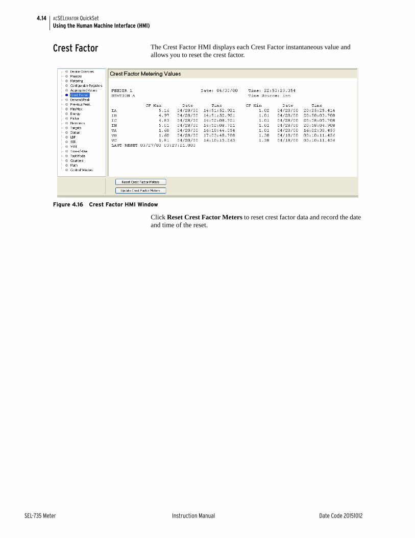
4.14
SEL-735 Meter Instruction Manual Date Code 20151012
ACSELERATOR QuickSetUsing the Human Machine Interface (HMI)
Crest Factor The Crest Factor HMI displays each Crest Factor instantaneous value and allows you to reset the crest factor.
Figure 4.16 Crest Factor HMI Window
Click Reset Crest Factor Meters to reset crest factor data and record the date and time of the reset.

4.15
Date Code 20151012 Instruction Manual SEL-735 Meter
ACSELERATOR QuickSetUsing the Human Machine Interface (HMI)
Demand/Peak The Demand/Peak HMI displays and resets demand and peak demand data. Figure 4.17 shows an example of the Demand/Peak HMI window.
Figure 4.17 Demand/Peak HMI Window
Follow these guidelines to control the Demand/Peak HMI.
➤ Click Time of Peak Demand to view the date and time associated with each peak demand.
➤ Click Update Demand/Peak Meters to populate the HMI with the most recent demand data.
➤ Click Reset Demand Meters to reset demand meter data and record the date and time of the reset.
➤ Click Reset Peak Meters to reset demand meter data and record the date and time of the reset.
Previous Peak The Previous Peak HMI displays previous peak demand.
Click Update Previous Peak Meters to update the Previous Peak HMI with the most recent previous peak data.
Min/Max The Min/Max HMI allows you to view Min and Max data and reset Min and Max meter data.

4.16
SEL-735 Meter Instruction Manual Date Code 20151012
ACSELERATOR QuickSetUsing the Human Machine Interface (HMI)
Figure 4.18 Min/Max HMI Window
Follow these guidelines to control the Min/Max HMI.
➤ Click Update Min/Max Meters to update the Min/Max HMI with the most recent data.
➤ Click Reset Min/Max Meters to reset the Min/Max data and record the date and time of the reset.
Flicker The Flicker HMI displays the flicker measurements of the SEL-735. When you first enter the Flicker HMI, the SEL-735 updates and displays all flicker values. Update the flicker values by clicking on the Update Flicker button near the lower left-hand corner of the Flicker HMI, as shown in Figure 4.19.
The Flicker HMI is only available for advanced and intermediate power quality SEL-735 devices.
Figure 4.19 Flicker HMI Window

4.17
Date Code 20151012 Instruction Manual SEL-735 Meter
ACSELERATOR QuickSetUsing the Human Machine Interface (HMI)
Harmonics The Harmonics HMI displays meter harmonic quantities in several user-selectable formats. You can then chart the harmonic data from the HMI.
Please see Section 5: Metering for a description of the Harmonics HMI window.
Targets The Targets HMI displays all Device Word bit states.
Status The Status HMI displays device diagnostics data. Figure 4.20 shows the Status HMI window.
Figure 4.20 Status HMI Window
Follow these guidelines to control the Status HMI.
➤ Click Clear Status to reset any locked-in diagnostics points.
➤ Click Get Diagnostics to download a diagnostics file from the meter. The file can then be sent to SEL for help in troubleshooting the device.
LDP (Load Profile), Sequential Events Recorders, VSSI, Time-of-Use
Please see Section 6: Logging for details on the following functions.
➤ Load Profile (LDP)
➤ Sequential Events Recorders
➤ Voltage Sag, Swell, Interruptions (VSSI)
➤ Time-of-Use
Test Mode Please see Section 9: Testing and Troubleshooting for details on the Time-of-Use HMI window.
Counters The Counters HMI displays instantaneous SELOGIC Counters values.
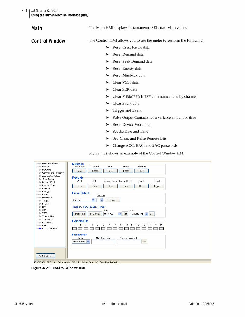
4.18
SEL-735 Meter Instruction Manual Date Code 20151012
ACSELERATOR QuickSetUsing the Human Machine Interface (HMI)
Math The Math HMI displays instantaneous SELOGIC Math values.
Control Window The Control HMI allows you to use the meter to perform the following.
➤ Reset Crest Factor data
➤ Reset Demand data
➤ Reset Peak Demand data
➤ Reset Energy data
➤ Reset Min/Max data
➤ Clear VSSI data
➤ Clear SER data
➤ Clear MIRRORED BITS® communications by channel
➤ Clear Event data
➤ Trigger and Event
➤ Pulse Output Contacts for a variable amount of time
➤ Reset Device Word bits
➤ Set the Date and Time
➤ Set, Clear, and Pulse Remote Bits
➤ Change ACC, EAC, and 2AC passwords
Figure 4.21 shows an example of the Control Window HMI.
Figure 4.21 Control Window HMI

4.19
Date Code 20151012 Instruction Manual SEL-735 Meter
ACSELERATOR QuickSetUsing the Human Machine Interface (HMI)
Retrieve Event Reports
You may use ACSELERATOR QuickSet to retrieve and view event reports. In order to view event reports you need to retrieve them from the meter and save them to a computer. Follow the steps below to retrieve events from the meter and save them to your computer.
Step 1. Click Tools > Events > Get Event Files.
If the meter contains events, then the Event History window opens similar to Figure 4.22, except ACSELERATOR QuickSet lists all of the events stored on the meter. If the meter does not contain any events, ACSELERATOR QuickSet prompts you with this information.
Step 2. Select the event or events to retrieve.
Step 3. Choose the event type.
ACSELERATOR QuickSet filters 16 Samples/cycle events at the fundamental frequency; these event types do not contain harmonics. Raw event reports contain all of the original event information.
Step 4. Click Get Selected Events to retrieve the selected events.
ACSELERATOR QuickSet retrieves the selected events from the meter and opens the Save Event Report window similar to Figure 4.23.
Step 5. Browse to a location to save the event report.
Step 6. Click Save.
Figure 4.22 Event History Window
Click to retrieve events
Choose event data format
Select the events to retrieve

4.20
SEL-735 Meter Instruction Manual Date Code 20151012
ACSELERATOR QuickSetUsing the Human Machine Interface (HMI)
Figure 4.23 Save Event Report Window
View Event Reports In order to view event reports from ACSELERATOR QuickSet, you must install ACSELERATOR Analytic Assistant® SEL-5601 Software. You may download the unlicensed program free of charge from www.selinc.com or by using SEL Compass®. Follow the steps below to view an event report.
Step 1. Click Tools > Events > View Event Files.
ACSELERATOR QuickSet prompts you with a window to open the event report.
Step 2. Browse to the event report’s directory.
Step 3. Click Open.
ACSELERATOR QuickSet opens ACSELERATOR Analytic Assistant main control window and displays the oscillography of the event report. Figure 4.24 shows the ACSELERATOR Analytic Assistant main control window and the available options to view the event report.
Figure 4.24 ACSELERATOR Analytic Assistant Main Control Window
Click to save event report
Click to activate one of the options:• Phasors• Oscillography• Harmonics• Event report text
Click to toggle the display On and Off

Date Code 20151012 Instruction Manual SEL-735 Meter
SET.1 of 18SEL-735 Settings SheetsGeneral Settings
Date _______________
SEL-735 Settings Sheets
General SettingsGeneral settings are available from the front panel and communications ports.
Identifier and Scaling SettingsMeter Identifier Labels
Meter Identifier (20 characters) MID :=
Terminal Identifier (20 characters) TID :=
Current and Potential Transformer Ratios
Phase Current Transformer Ratio CTR:1 (1.0000–6000) CTR :=
Potential Transformer Ratio PTR:1 (1.0000–10000) PTR :=
Analog Quantity Scaling Settings
Voltage Scaling (UNITY, KILO, MEGA) VOLT_SCA :=
Power and Demand Scaling (UNITY, KILO, MEGA) POWR_SCA :=
Energy Scaling (UNITY, KILO, MEGA) ENRG_SCA :=
Present Analog Quantities in Primary (Y, N) PRI_SCA :=
Instrument Transformer CompensationFor the following settings, replace x with the Phase A, B, or C, and replace n with the calibration point number. Form 5 meters do not have Phase B CT compensation. Form 5 and Form 36 meters do not have Phase B PT compensation.
Enable ITC for Current (N, 1–6) EITCI :=
Secondary Amps for Calibration Point n (0.01–20.00 A) ICAL_n :=
CT Ratio Correction Factor (0.9800–1.0200) IRCFx_n :=
CT Phase Angle Minutes (–300.0 to 300.0) IPAMx_n :=
Enable ITC for Voltage (N, 1–6) EITCV :=
Secondary Volts for Calibration Point n (5.00–300.00 V) VCAL_n :=
PT Ratio Correction Factor (0.9800–1.0200) VRCFx_n :=
PT Phase Angle Minutes (–300.0 to 300.0) VPAMx_n :=

SET.2 of 18 SEL-735 Settings SheetsGlobal Settings
SEL-735 Meter Instruction Manual Date Code 20151012
Date _______________
Global SettingsGain Adjustment Settings
Watt Gain % (–10.00 to 10.00) WGAIN :=
VAR Gain % (–10.00 to 10.00) VARGAIN :=
Advanced Global SettingsWatt/VAR angle cutoff (OFF, 1–10 degrees) ANGCUT :=
Starting Current Threshold (x–10 mA)(x is 1.0 mA for CL2/10/20 meters and 5.0 mA for CL10/20 meters)
IST :=
Starting Current Type (ALL, RMS_ONLY) IST_TYPE :=
Phase rotation (ABC, ACB) PHROT :=
Date format (MDY, YMD, DMY) DATE_F :=
IRIG Time Source Type (IRIG, IEEE*) (Hidden and forced to IEEE if EPMIP > 0)
TSTYPE :=
*(When TSTYPE := IEEE, the device requires IEEE C37.118 control bits to be sent from the IRIG clock. If TSTYPE is set to IEEE, but control bits are not included in the IRIG signal, then the device word bit TIRIG will continually toggle.)
Offset from UTC (–24.00 to 24.00 hours) UTC_OFF :=
Time Change Flag Threshold (1 to 59 sec) TIME_CHG :=
SynchrophasorsMessages per Second
(1, 2, 5, 10, 25, or 50 when frequency := 50 Hz)(1, 2, 4, 5, 10, 12, 15, 20, 30, or 60 when frequency := 60 Hz)
MRATE :=
Station Name (16 characters) PMSTN :=
PMU Hardware ID (1–65534) PMID :=
Phasor Data Set, Voltages (V1, PH, ALL, NA) PHDATAV :=
Phase Voltage Angle Compensation (–179.99 to 180 deg) VCOMP :=
Phasor Data Set, Currents (I1, PH, ALL, NA) PHDATAI :=
Phase Angle Current Compensation (–179.99 to 180 deg) ICOMP :=
Number of PMU Analog Values (0–4) NUMANA :=
PMU Analog Quantity 1 PMUAQ1 :=
PMU Analog Quantity 2 PMUAQ2 :=
PMU Analog Quantity 3 PMUAQ3 :=
PMU Analog Quantity 4 PMUAQ4 :=

Date Code 20151012 Instruction Manual SEL-735 Meter
SET.3 of 18SEL-735 Settings SheetsFront Panel
Date _______________
Number of 16-bit Digital Status Words (0, 1) NUMDSW :=
Trigger Reason Bit 1 (SELOGIC) TREA1 :=
Trigger Reason Bit 2 (SELOGIC) TREA2 :=
Trigger Reason Bit 3 (SELOGIC) TREA3 :=
Trigger Reason Bit 4 (SELOGIC) TREA4 :=
PMU Trigger (SELOGIC) PMTRIG :=
Front PanelFront-Panel Display Settings
Front-Panel Time-out (OFF, 1–120 min) FP_TO :=
Front-Panel Contrast (1–8) FP_CONT :=
Display Update Rate in seconds (1–60) SCROLD :=
Front-Panel Display Point SettingsReplace n with the display point value 01–16.
Logic String DPn :=
Display when Logic = 1 (64 characters, NA to null) DPn_1 :=
Display when Logic = 0 (64 characters, NA to null) DPn_0 :=
Front-Panel LED Logic SettingsReplace n with the LED value 01–14. T07_LED—T14_LED is available only when PBDFLT = Y.
Pushbutton Default Function (Y, N) PBDFLT :=
Front-Panel LEDn Logic Tn_LED :=
Metering SettingsDemand
EDEM Enable Demand Metering Method
Demand Metering (THM = Thermal, ROL = Rolling, BLOK = Block)
EDEM :=
EDEM Enable Demand Metering Method
Time constant (1, 5, 10, 15, 30, 60 minutes) DMTC :=
Sub-interval time constant (see Table SET.1) (Hidden if EDEM set to THM or BLOK)
DMSI :=

SET.4 of 18 SEL-735 Settings SheetsLoss Compensation Settings
SEL-735 Meter Instruction Manual Date Code 20151012
Date _______________
Demand Block Time (OFF, 1–300 minutes) DBLOCK :=
Fault Bit Block (SELOGIC control equation) FLTBLK :=
End of Interval Pulse Timer (OFF, 1–5 s) EOIPT :=
Predicted Peak Demand Quantity (any present interval Demand Analog Quantity) (Hidden if EDEM = THRM)
PRED :=
Peak Demand Alarm Level (Primary units; kilo scaling for power quantities, unity scaling for current quantities units 0.00–1,000,000.00) (Hidden if EDEM =THRM)
PREDAL :=
Loss Compensation SettingsThe following settings are available when ETLLC = Y.
ETLLC Enable Transformer/Line Losses CompensationEnable Transformer/Line Losses Compensation (Y, N) ETLLC :=
Meter Position SettingsSystem Billing Point (1–4) BPOS :=
System Metering Point (1–4) MPOS :=
Transformer Losses SettingsTransformer Copper Losses Compensation (Y, N)
(Hidden if ETLLC = N)ELCU :=
Transformer Iron Losses Compensation (Y, N)(Hidden if ETLLC = N)
ELFE :=
Transformer Copper Watt Losses (0.00001–10000.00000 kW) LWCU :=
Transformer Iron Watt Losses (0.00001–10000.00000 kW) LWFE :=
Transformer 3-Phase MVA Rating (0.00001–10000.00000 MVA) MVA :=
Primary Line-to-Line Metered Voltage (0.00001–10000.00000 kV) KVLL :=
Transformer Percentage Impedance (0.001–19.999%) %Z :=
Transformer Percentage Exciting Current (0.001–19.999%) %IMAG :=
Table SET.1 DMSI Range
DMTC Value DMSI Range
1 1 min
5 5, 1 min
10 10, 5, 2, 1 min
15 15, 5, 3 min
30 30, 15, 10, 6, 5, 3 min
60 60, 30, 20, 15, 12, 10, 6, 5 min

Date Code 20151012 Instruction Manual SEL-735 Meter
SET.5 of 18SEL-735 Settings SheetsEnergy Preload Settings
Date _______________
Supply and Load Line Losses SettingsSupply Line Resistance (0.0000–999.9999 Ohms, primary) SLR :=
Supply Line Reactance (0.0000–999.9999 Ohms, primary) SLX :=
Load Line Resistance (0.0000–999.9999 Ohms, primary) LLR :=
Load Line Reactance (0.0000–999.9999 Ohms, primary) LLX :=
Power Transformer Turns Ratio (VSupply/VLoad) XFTR :=
Energy Preload SettingsReplace n with the phase number of A, B, or C, or 3 for three-phase. Single-phase settings are only available with Form 9 and Form 36 meters.
Meter Energy Preload Settings (Compensated)
Meter Energy Preload Settings (Uncompensated)
Load Profile Acquisition Rate (5, 10, 15, 30, 60 min) LDAR :=
Phase n KWh Delivered (0–999999999999.999 kWh) KWHn_DEL :=
Phase n KWh Received (0–999999999999.999 kWh) KWHn_REC :=
Phase n KVAh Delivered (0–999999999999.999 kVAh) KUHn_DEL :=
Phase n KVAh Received (0–999999999999.999 kVAh) KUHn_REC :=
Phase n KVARh Delivered Lag(0–999999999999.999 kVARh)
KQHn_DEL_LG :=
Phase n KVARh Delivered Lead(0–999999999999.999 kVARh)
KQHn_DEL_LG :=
Phase n KVARh Received Lag(0–999999999999.999 kVARh)
KQHn_REC_LG :=
Phase n KVARh Received Lead(0–999999999999.999 kVARh)
KQHn_REC_LG :=
Phase n KWh Delivered (0–999999999999.999 kWh) KWHn_DEL_UC :=
Phase n KWh Received (0–999999999999.999 kWh) KWHn_REC_UC :=
Phase n KVARh Delivered Lag(0–999999999999.999 kVARh)
KQHn_DEL_LG_UC :=
Phase n KVARh Delivered Lead(0–999999999999.999 kVARh)
KQHn_DEL_LD_UC :=
Phase n KVARh Received Lag(0–999999999999.999 kVARh)
KQHn_REC_LG_UC :=
Phase n KVARh Received Lead(0–999999999999.999 kVARh)
KQHn_REC_LD_UC :=

SET.6 of 18 SEL-735 Settings SheetsConfigurable Registers
SEL-735 Meter Instruction Manual Date Code 20151012
Date _______________
Configurable RegistersThe Configurable Registers settings cannot be preconfigured when ordering an SEL-735.
Inputs/OutputsKYZ Pulse Outputs
KYZ Pulse n SettingsReplace n with the KYZ channel number 1–4.
KEn Scale (PRI, SEC) KEn_SCALE :=
Watthour Constant n (0.0001–9,999.0000) KEn :=
KEn Units (UNITY, KILO, MEGA) KEn_UNIT :=
Demand Type to Output n KYZDn :=
KYZ Minimum Pulse Width n (25, 50, 75, 100 ms) MYZPWn :=
KYZ Output Contact KEn_OUT :=
(Available only with solid-state output contacts.)
KYZ Pulse Test Mode Setting
Watthour Constant (0.0001–9999) KET :=
Configurable Register (1–1000) CONFIGREG :=
Analog Quantity (Analog Quantity) NAME :=
Alias String (39 chars max) ALIAS :=
Units String (15 chars max) UNITS :=
Decimal Places (0–6) DECIMALS :=
Leading Zeros (Y, N) LEADINGZEROS :=
Large Font (Y, N) LARGEFONT :=
User Scale (Y, N) SCALEUSER :=
Scale (–1 x 10¹⁰ to 1 x 10¹⁰) SCALEVALUE :=
Offset (–1 x 10¹⁰ to 1 x10¹⁰) OFFSET :=
Scale Type (PRIMARY, SECONDARY) SCALETYPE :=
Units Type (UNITY, KILO, MEGA) UNITSTYPE :=
Rollover Type (DIALS, VALUE) ROLLOVERTYPE :=
Rollover Dials (5–12) ROLLOVERDIALS :=
Rollover Value (0 to 1 x 10¹⁵) ROLLOVERVALUE :=

Date Code 20151012 Instruction Manual SEL-735 Meter
SET.7 of 18SEL-735 Settings SheetsEvents and Logging
Date _______________
Output ContactsOutput Contact Equations
Replace n with the output contact number 01–03.
Output Contact 1n OUT1n :=
Output Contact Equations (Extra I/O Board)Replace n with the output contact number 01–04.
Output Contact 4n OUT4n
Optoisolated Input Timers 101–102Replace n with the optoisolated input number 01–02.
Input IN1n debounce time (0–8 ms, AC) IN1nD :=
Optoisolated Input Timers 401–404Replace n with the optoisolated input number 01–04.
Input IN4n debounce time (0–8 ms, AC) IN4nD :=
Analog Output SettingsReplace n with a value 01–04.
AOn Analog Quantity AOnAQ :=
AOn Analog Quantity Low (–2147483647.000–2147483647) AOnAQL :=
AOn Analog Quantity High (–2147483647.000–2147483647) AOnAQH :=
AOn Low Analog Output Value (±1.200 or ±24.000) AOnL :=
AOn High Analog Output Value (±1.200 or ±24.000) AOnH :=
Events and LoggingLoad Profile Settings
Billing RecorderLoad profile settings consist of 1–12 recorders, each containing as many as 16 elements from analog quantities.
Recorder Function (EOI, AVG, COI, MAX, MIN) LDFUNC1 :=
Load Profile List (16 elements max., NA to null) LDLIST1 :=
Load Profile Acquisition Rate (3–59 s; 1, 2, 3, 5, 10, 15, 30, 60, 120 minutes)
LDAR1 :=
Load Profile Maximum Duration (0.05–5000.00 days) LMDUR1 :=
(3–59 s requires Advanced or Intermediate PQ and Recording)

SET.8 of 18 SEL-735 Settings SheetsEvents and Logging
SEL-735 Meter Instruction Manual Date Code 20151012
Date _______________
Recorder nFor additional recorders, replace n with a value of 2–12. Additional recorders require Advanced or Intermediate PQ and Recording.
Recorder Function (EOI, AVG, COI, MAX, MIN) LDFUNCn :=
Load Profile List (16 elements max., NA to null) LDLISTn :=
Load Profile Acquisition Rate (3–59 s; 1, 2, 3, 5, 10, 15, 30, 60, 120 minutes)
LDARn :=
Load Profile Maximum Duration (0.05–5000.00 days) LMDURn :=
(3–59 s requires Advanced or Intermediate PQ and Recording)
Voltage Sag/Swell/Interruption SettingsVoltage Base (20.00–300.00 VL-N for Form 9 and
36 meters. 20.00–480.00 VL-L for Form 5 meters.)VBASE :=
AVG_TIME (OFF, 1–10 min) AVG_TIME :=
The following Voltage/Sag/Swell/Interruption Settings are in percent of VBASE.
L-N Voltage Interrupt (OFF, 5.00–99.00) VINT :=
Voltage Interruption Hysteresis (0.00–10.00) VINTHYS :=
L-N Voltage Sag (OFF, 10.00–99.00) VSAG :=
Voltage Sag Hysteresis (0.00–10.00) VSAGHYS :=
L-N Voltage Swell (OFF, 101.00–180.00) VSWELL :=
Voltage Swell Hysteresis (0.00–10.00) VSWELHYS :=
Harmonic AlarmsHarmonic Triggers
Replace n with the harmonic component 02–15.
The following Harmonic Alarm settings are in percent of VBASE.
Harmonic Trigger Quantities (ALL, VOLTAGE, CURRENT) HARMTRIG :=
nth Harmonic Threshold (OFF, 3–100%) HARMn :=
Interharmonic Quantities
Include Interharmonic Quantities (Y, N) INCIHQ :=
(Requires Advanced PQ and Recording.)
Sequential Events Recorder SettingsReplace n with the Sequential Events Recorder number 1–3.
Sequential Events Recorder n (24 elements max., NA to null) SERn :=

Date Code 20151012 Instruction Manual SEL-735 Meter
SET.9 of 18SEL-735 Settings SheetsSELOGIC Control Equations
Date _______________
Event ReportReplace n with the Event Report Trigger List number 1–3. Includes optional features.
ER Trigger List n ERn :=
Waveform Capture Sample Rate (16, 128, 512 samples per cycle)
SRATE :=
Event Length (15, 30, 60, 120, 300, 600 cycles) LER :=
(15 cycles only available with Basic PQ and Recording.)
(600 cycles not available when SRATE = 512.)
Prefault Length (1–595 cycles) PRE :=
(The Prefault Length must be at least 5 cycles less than the Event Length.)
SELOGIC Control EquationsLatch Bits
Latch Bit SettingsReplace n with the Latch Bit number 01 –16.
Set Latch Bit LTn SETn :=
LReset Latch Bit LTn RSTn :=
Control EquationsReplace n with the SELOGIC control equation number 01–16.
SELOGIC Control Equation Variable SVn SVn :=
SVn Timer Pickup (0.000–1000000.000 seconds) SVnPU :=
SVn Timer Dropout (0.000–1000000.000 seconds) SVnDO :=
Math VariablesMath Variable Equations
Replace n with the Math Variable number 01–16.
SELOGIC Math Equation Variable MVn MVn :=
Counter EquationsCounter Equation Settings
Replace n with the Counter number 01–16.
Current Value (0–999999) SCnCV :=
(SCnCV must be less than or equal to SCnPV.)
Counter Preset Value (1–999999) SCnPV :=
Reset (SELOGIC Equation) SCnR :=
Load (SELOGIC Equation) SCnLD :=
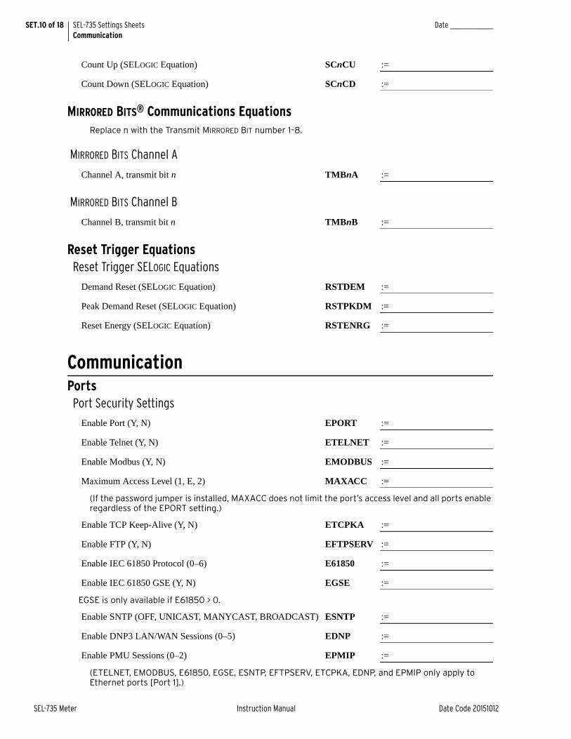
SET.10 of 18 SEL-735 Settings SheetsCommunication
SEL-735 Meter Instruction Manual Date Code 20151012
Date _______________
Count Up (SELOGIC Equation) SCnCU :=
Count Down (SELOGIC Equation) SCnCD :=
MIRRORED BITS® Communications EquationsReplace n with the Transmit MIRRORED BIT number 1–8.
MIRRORED BITS Channel A
Channel A, transmit bit n TMBnA :=
MIRRORED BITS Channel B
Channel B, transmit bit n TMBnB :=
Reset Trigger EquationsReset Trigger SELOGIC Equations
Demand Reset (SELOGIC Equation) RSTDEM :=
Peak Demand Reset (SELOGIC Equation) RSTPKDM :=
Reset Energy (SELOGIC Equation) RSTENRG :=
CommunicationPorts
Port Security Settings
Enable Port (Y, N) EPORT :=
Enable Telnet (Y, N) ETELNET :=
Enable Modbus (Y, N) EMODBUS :=
Maximum Access Level (1, E, 2) MAXACC :=
(If the password jumper is installed, MAXACC does not limit the port’s access level and all ports enable regardless of the EPORT setting.)
Enable TCP Keep-Alive (Y, N) ETCPKA :=
Enable FTP (Y, N) EFTPSERV :=
Enable IEC 61850 Protocol (0–6) E61850 :=
Enable IEC 61850 GSE (Y, N) EGSE :=
EGSE is only available if E61850 > 0.
Enable SNTP (OFF, UNICAST, MANYCAST, BROADCAST) ESNTP :=
Enable DNP3 LAN/WAN Sessions (0–5) EDNP :=
Enable PMU Sessions (0–2) EPMIP :=
(ETELNET, EMODBUS, E61850, EGSE, ESNTP, EFTPSERV, ETCPKA, EDNP, and EPMIP only apply to Ethernet ports [Port 1].)

Date Code 20151012 Instruction Manual SEL-735 Meter
SET.11 of 18SEL-735 Settings SheetsCommunication
Date _______________
Communications SettingsPort 1 (Ethernet) Settings
Telnet Port One (23, 1025–65534) TPORT :=
Telnet Port One Idle Time (OFF, 1–30 min) TIDLE :=
IP Address IPADDR :=
Subnet Mask SUBNETM :=
Default Router DEFRTR :=
Table SET.2 defines the valid IP Address settings. The most significant byte (MSB) of the IP Address determines the valid range of the setting. For example, if the IP Address MSB is 192, then valid IP Addresses range from 192.0.1.1 to 192.255.254.254.
Keep-Alive Settings
The following settings are used if ETCPKA = Y.
TCP Keep-Alive Idle Range (1–20 s) KAIDLE :=
TCP Keep-Alive Interval Range (1–20 s) KAINTV :=
TCP Keep-Alive Count Range (1–20 messages) KACNT :=
FTP Settings
The following settings are used if EFTPSERV = Y.
FTP User Name FTPUSER :=
FTP Connect Banner FTPCBAN :=
FTP Idle Timeout (5–255 min) FTPIDLE :=
SNTP Settings
The following settings are only used if ESNTP ≠ OFF.
Primary Server IP Address SNTPPSIP :=
Backup Server IP Address SNTPBSIP :=
(SNTPBSIP only available if ESNTP = UNICAST)
SNTP IP (Local) Port Number (1–65534) SNTPPORT :=
SNTP Update Rate (15–3600 s) SNTPRATE :=
SNTP Timeout (5–20 s) SNTPTO :=
(SNTPTO only available if ESNTP = UNICAST or MANYCAST)
Table SET.2 Valid IP Addresses
IP Address MSBValid IP Address Range
From To
1–126 1.0.0.1 126.255.255.254
128–191 128.1.0.1 191.255.255.254
192–223 192.0.1.1 223.255.254.254

SET.12 of 18 SEL-735 Settings SheetsCommunication
SEL-735 Meter Instruction Manual Date Code 20151012
Date _______________
DNP Ethernet Session SettingsThe following settings are only available on Port 1 and when EDNP > 0.
DNP TCP and UDP Port (1–65534) DNPNUM :=
DNPNUM applies to all Ethernet DNP sessions.
DNP Address (0–65519) DNPADR :=
DNPADR applies to all Ethernet DNP sessions.
PMU Session Settings
PMU Output 1 Transport Scheme (OFF, TCP, UDP_S, UDP_T, UDP_U)
PMOTS1 :=
PMU Output 1 Client IP (Remote) Address (www.xxx.yyy.zzz) PMOIPA1 :=
PMU Output 1TCP/IP (Local) Port Number (1–65534) PMOTCP1 :=
PMU Output 1 UDP/IP Data (Remote) Port Number (1–65534) PMOUDP1 :=
PMU Output 2 Transport Scheme (OFF, TCP, UDP_S, UDP_T, UDP_U)
PMOTS2 :=
PMU Output 2 Client IP (Remote) Address (www.xxx.yyy.zzz) PMOIPA2 :=
PMU Output 2 TCP/IP (Local) Port Number (1–65534) PMOTCP2 :=
PMU Output 2 UDP/IP Data(Remote) Port Number (1–65534) PMOUDP2 :=
Port F, Port 2, Port 3, Port 4 Settings
Communications Interface (232, 485, Modem) COMMINF :=
(COMMINF is only available on Port 4.)
Protocol (SEL, MOD, DNP, LMD*, MBA*, MB8A*, MBB*, MB8B*)
PROTO :=
*Not available on Port F.
Protocol Settings:
Set PROTO = SEL for standard SEL ASCII protocol and MV-90 protocol.
Set PROTO = MOD for Modbus RTU Protocol. Refer to Appendix E: Modbus Communications Protocol for details on Modbus protocol.
Set PROTO = DNP for Distributed Network Protocol (DNP). Refer to Appendix D: Distributed Network Protocol for details on DNP protocol.
Set PROTO = LMD for SEL Distributed Port Switch Protocol.
Set PROTO = MBA, MBB, MB8A, or MB8B for MIRRORED BITS protocol. Refer to Appendix F: MIRRORED BITS Communications for details on MIRRORED BITS communications.
SPEEDs 57600 and 115200 are not available on Port F.
Baud Rate (300, 1200, 2400, 4800, 9600, 19200, 38400, 57600, 115200)
SPEED :=
Data Bits (6, 7, 8) BITS :=
Parity (O, E, N) {Odd, Even, None} PARITY :=
Stop Bits (1, 2) STOP :=

Date Code 20151012 Instruction Manual SEL-735 Meter
SET.13 of 18SEL-735 Settings SheetsCommunication
Date _______________
Enable Hardware Handshaking (Y, N, MBT) RTSCTS :=
RTSCTS not available on Port 1 (Ethernet), Port 4A (EIA-485), EIA-485 Port 3, or a port configured for SEL Distributed Port Switch Protocol (LMD). With RTSCTS = Y, the meter will not send characters until the CTS input is asserted. If the meter is unable to receive characters, it deasserts the RTS line.
RTSCTS = MBT is only available when SPEED = 9600. In this mode, the meter deasserts the RTS line and does not monitor the CTS line. This selection is normally used with MIRRORED BITS communications, PROTO = MBA or MBB. See Appendix F: MIRRORED BITS Communications for more detail.
Set RTSCTS = Y to enable hardware handshaking.
Minutes to Port Time-out (0–30) T_OUT :=
Set T_OUT = 0 for no port time out.
Enable Port Power (Y, N) EPP :=
Enable or disable Pin 1 +5 V power on EIA-232 Port 2 or Port 3. Port power is disabled by default.
Send Auto Messages to Port (Y, N) AUTO :=
AUTO only available if PROTO = SEL or LMD. Set AUTO = Y to allow automatic messages at the serial port.
Fast Operate Enable (Y, N) FASTOP :=
FASTOP only available if PROTO = SEL or LMD.
Set FASTOP = Y to enable binary Fast Operate messages at the serial port. Set FASTOP = N to block binary Fast Operate messages. Refer to Appendix C: SEL Communications Processors for the description of the SEL-735 Fast Operate commands.
Sync. Phasor Transmission Data Set (V1, V, A) PMDATA :=
PMDATA only available if PROTO = SEL or LMD.
Address of Sync. Phasor Measurement Data (0x–FFFFFFFFh) PMADDR :=
PMADDR only available if PROTO = SEL or LMD.
LMD Protocol Settings The following settings are used if PROTO = LMD.
LMD Prefix (@, #, $, %, &) PREFIX :=
LMD Address (1–99) ADDR :=
LMD Settling Time (0.00–30.00 s) SETTLE :=
Modem SettingsModem Initialization AT String ATSTRING :=
ATSTRING is only available if COMMINF = MODEM.
DNP Serial SettingsThe following settings are only available on Port F, Port 2, Port 3, and Port 4.
DNP Address (0–65519) DNPADR :=
DNP Address to Report to (1–65519) REPADR :=
DNP Session Map (1, 2) DNPMAP :=

SET.14 of 18 SEL-735 Settings SheetsCommunication
SEL-735 Meter Instruction Manual Date Code 20151012
Date _______________
Event Data by Class
Class for Binary Event Data (0–3) ECLASSB :=
Class for Counter Event Data (0–3) ECLASSC :=
Class for Analog Event Data (0–3) ECLASSA :=
Scaling Decimal Places
Amps Scaling Decimal Places (0–6) DECPLA :=
Voltages Scaling Decimal Places (0–6) DECPLV :=
Misc Data Scaling Decimal Places (0–6) DECPLM :=
Energy Counter Scaling Decimal Places (0–6) DECPLE :=
Reporting Dead-band Counts
Amps Reporting Dead-band Counts (0–32767) ANADBA :=
Volts Reporting Dead-band Counts (0–32767) ANADBV :=
Misc Data Reporting Dead-band Counts (0–32767) ANADBM :=
Timeouts
Minutes for Request Interval (I, M, 1–32767) TIMERQ :=
Seconds to Select/Operate Time-Out (0.0–30) STIMEO :=
Event Message Confirm Timeout (1–50 s) ETIMEO :=
Data Link
Retries (0–15) DRETRY :=
Seconds to Time-Out (0–5) DTIMEO :=
(DTIMEO only available if DRETRY > 0.)
Class 0 Reporting
Class 0 Response Counter Object (20, 21, Both) CZPCT :=
Unsolicited Messages
Enable Unsolicited Reporting (Y, N) UNSOL :=
The following Unsolicited Message settings are only available if UNSOL = Y.
Enable Unsolicited Reporting at Power-Up (Y, N) PUNSOL :=
Number of Events to Transmit On (1–200) NUMEVE :=
Oldest Event to Transmit On (0–99999 s) AGEEVE :=
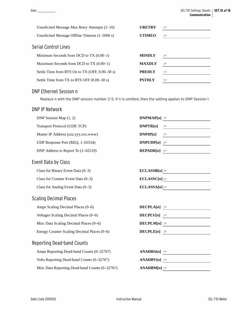
Date Code 20151012 Instruction Manual SEL-735 Meter
SET.15 of 18SEL-735 Settings SheetsCommunication
Date _______________
Unsolicited Message Max Retry Attempts (2–10) URETRY :=
Unsolicited Message Offline Timeout (1–5000 s) UTIMEO :=
Serial Control Lines
Minimum Seconds from DCD to TX (0.00–1) MINDLY :=
Maximum Seconds from DCD to TX (0.00–1) MAXDLY :=
Settle Time from RTS On to TX (OFF, 0.00–30 s) PREDLY :=
Settle Time from TX to RTS OFF (0.00–30 s) PSTDLY :=
DNP Ethernet Session nReplace n with the DNP session number 2–5. If n is omitted, then the setting applies to DNP Session 1.
DNP IP Network
DNP Session Map (1, 2) DNPMAP[n] :=
Transport Protocol (UDP, TCP) DNPTR[n] :=
Master IP Address (zzz.yyy.xxx.www) DNPIP[n] :=
UDP Response Port (REQ, 1–65534) DNPUDP[n] :=
DNP Address to Report To (1–65519) REPADR[n] :=
Event Data by Class
Class for Binary Event Data (0–3) ECLASSB[n] :=
Class for Counter Event Data (0–3) ECLASSC[n] :=
Class for Analog Event Data (0–3) ECLASSA[n] :=
Scaling Decimal Places
Amps Scaling Decimal Places (0–6) DECPLA[n] :=
Voltages Scaling Decimal Places (0–6) DECPLV[n] :=
Misc Data Scaling Decimal Places (0–6) DECPLM[n] :=
Energy Counter Scaling Decimal Places (0–6) DECPLE[n] :=
Reporting Dead-band Counts
Amps Reporting Dead-band Counts (0–32767) ANADBA[n] :=
Volts Reporting Dead-band Counts (0–32767) ANADBV[n] :=
Misc Data Reporting Dead-band Counts (0–32767) ANADBM[n] :=

SET.16 of 18 SEL-735 Settings SheetsCommunication
SEL-735 Meter Instruction Manual Date Code 20151012
Date _______________
Timeouts
Minutes for Request Interval (I, M, 1–32767) TIMERQ[n] :=
Seconds to Select/Operate Time-Out (0.0–30) STIMEO[n] :=
Event Message Confirm Timeout (1–50 s) ETIMEO[n] :=
Data Link
Seconds to Send Data Link Heartbeat (0–7200) DNPINA[n] :=
Class 0 Reporting
Class 0 Response Counter Object (20, 21, Both) CZPCT[n] :=
Unsolicited Messages
Enable Unsolicited Reporting (Y, N) UNSOL[n] :=
The following Unsolicited Message settings are only available if UNSOL = Y.
Enable Unsolicited Reporting at Power-Up (Y, N) PUNSOL[n] :=
Number of Events to Transmit On (1–200) NUMEVE[n] :=
Oldest Event to Transmit On (0–99999 s) AGEEVE[n] :=
Unsolicited Message Max Retry Attempts (2–10) URETRY[n] :=
Unsolicited Message Offline Timeout (1–5000 s) UTIMEO[n] :=
DNP Map SettingsDNP Map n
Replace n with the DNP map number 1 or 2.
Binary Input n BI_MAPn :=
Binary Output n BO_MAPn :=
Analog Input n AI_MAPn :=
Analog Output n AO_MAPn :=
Counter Input n CO_MAPn :=
Fast MessagesEnable Energy Message (Y, N) FMR1 :=
Enable 4–Quadrant Demand Message (Y, N) FMR2 :=
Enable 4–Quadrant Peak Demand Message (Y, N) FMR3 :=
Enable 4–Quadrant Meter Message (Y, N) FMR4 :=
Uncompensated Quantities in Fast Message (Y, N) FMQ_UC :=

Date Code 20151012 Instruction Manual SEL-735 Meter
SET.17 of 18SEL-735 Settings SheetsCommunication
Date _______________
Modem SettingsThe following settings are only available when COMMINF = MODEM.
Dial Out When a New Event Is Recorded (Y, N) DIALOUT :=
DIALOUT only available on Modem ports and PROTO = SEL.
Event Notification String (30 chars max.) EVE_STR :=
EVESTR only available on Modem port and DIALOUT = Y.
ID Command String (20 chars max.) ID_CMD :=
ID_CMD only available on Modem port and DIALOUT = Y.
Connection ID String (20 chars max.) CONN_ID :=
CONN_ID only available on Modem ports and DIALOUT = Y.
Modem Connected to Port (Y, N) MODEM :=
MODEM only available when PROTO = DNP and COMMINF = 232 or the physical port is an EIA-232 port.
Modem Initialization at String (30 chars max.) ATSTRING :=
ATSTRING only available on Modem port.
Modem Startup String (30 chars max.) MSTR :=
Phone Number for Dial-Out (30 chars max.) PH_NUM :=
Time to Attempt Dial (5–300 s) MDTIME :=
Time Between Dial-Out Attempts (5–3600 s) MDRET :=
MSTR, PH_NUM, MDTIME, and MDRET are only available on EIA-232 serial ports and MODEM = Y with PROTO = DNP; or PROTO = SEL with DIALOUT = Y. Additionally, MSTR is not available on Port 4.
Modbus Protocol SettingsModbus Slave ID (1–247) SLAVEID :=
SLAVEID is only available when PROTO = MOD.

This page intentionally left blank

Date Code 20151012 Instruction Manual SEL-735 Meter
Section 5Metering
OverviewThis section explains the following SEL-735 functions.
➤ IEC 61000-4-30 Testing and Measurement Techniques—Power Quality Measurement Methods on page 5.2
➤ Measurement Aggregation on page 5.2
➤ Four-Quadrant VAR Metering on page 5.5
➤ Demand Metering on page 5.10
➤ Energy Metering on page 5.31
➤ Minimum/Maximum Metering on page 5.36
➤ Crest Factor Metering on page 5.38
➤ Harmonic Metering on page 5.39
➤ Flicker Metering on page 5.45
➤ Transformer/Line Loss Compensation on page 5.45
➤ Configurable Registers on page 5.51
➤ Voltage, Current, and Power Calculations on page 5.55
Each section also describes how to access the metered data. Analog quantities are divided into similar measurement categories and are available to all interfaces. Please see Appendix G for a list of all supported analog quantities.
Form Factor SupportThe SEL-735 supports the three following metering form factors:
1. Form 5, 2-Element, Three-Wire Delta
2. Form 9, 3-Element, Four-Wire Wye
3. Form 36, 2 1/2-Element, Four-Wire Wye
Form 5 and Form 9 meters are Blondel compliant, whereas Form 36 meters are not Blondel compliant. Form 36 metering relies on the assumption that the three-phase voltages are balanced and that voltage VBN can be calculated by VBN = –(VAN + VCN). If the voltages are not balanced, the reported values will not be accurate.
To change the meter’s form factor, issue the FORm command from the 2AC access level. The command syntax is shown below.
Syntax: FORm x [x is the desired form factor 5 (form 5), 6 (form 36), or 9 (form 9)]

5.2
SEL-735 Meter Instruction Manual Date Code 20151012
MeteringIEC 61000-4-30 Testing and Measurement Techniques—Power Quality Measurement Methods
IEC 61000-4-30 Testing and Measurement Techniques—Power Quality Measurement Methods
The SEL-735 uses the IEC standard 61000-4-30 Testing and Measurement Techniques—Power Quality Measurement Methods when calculating quantities.
The standard describes very specific calculation and aggregation methods. The list below defines the SEL-735 deviations from the exact definition of the standard.
➤ For zero-sequence imbalance, use SELOGIC math variable equations as demonstrated below.
➤ Interharmonic quantities update every 10/12 cycles. The SEL-735 Load Profile Recorder can average interharmonics over 3-second, 10-minute, and 2-hour intervals.
➤ Harmonic reports include individual components, groups, and phase angles, but not subgroups.
➤ Voltage sag/swell/interruption disturbances sample over a half-cycle window instead of a 1-cycle window.
➤ The time window for harmonic calculations is within ±0.06 percent.
Measurement AggregationThe SEL-735 performs aggregation of metered quantities for 3 seconds, 10 minutes, and 2 hours in accordance with IEC 61000-4-30.

5.3
Date Code 20151012 Instruction Manual SEL-735 Meter
MeteringMeasurement Aggregation
Analog Quantities The following quantities are available as aggregated quantities:
➤ Voltage, Current, and Power
➤ Current and Voltage Imbalance
➤ Voltage and Current Harmonic Magnitudes
➤ Voltage and Current Total Harmonic distortion
Processing The SEL-735 uses the following equation to perform aggregation.
Aggregation Time Periods
150/180 CyclesAggregation calculates 15 consecutive 10/12 cycle data synchronized to the system frequency.
10 MinuteEach 10-minute aggregation calculation begins on an absolute 10-minute boundary of the RTC.
2 HourEach 2-hour aggregation calculates from 12 consecutive sets of 10-minute values.
Aggregation Reset The 10-minute and 2-hour aggregated values and time stamps reset any time the device resets or the system time changes more than the TIME_CHG setting. The values report zero until the conclusion of the next whole aggregation period.
Flagging The SEL-735 Sequential Events Recorder (SER) flag analog data stored in the load profile recorder to meet the requirements of IEC 61000-4-30. Add the Device Word bits in Table 5.1 to the SEL-735 SER equation, as shown in Figure 5.1.
where:ValueAggregate = the time-aggregated value.
Input = the value to aggregate.N = the number of accumulations performed during the
aggregation period.
Aggregation Interval N Input
150/180 cycles 15 10/12 cycle data
10 minutes 3000a
a This value varies depending on the system frequency.
10/12 cycle data
2 hour 12 10 minute data
ValueAggregate1N----
N 1–
i 0= input i[ ]2=

5.4
SEL-735 Meter Instruction Manual Date Code 20151012
MeteringMeasurement Aggregation
During an event, the SEL-735 records every Device Word bit change with a time stamp. View the LDP records to determine if any logged quantity is associated with an event flag.
Figure 5.1 Selected Sag and Swell Elements in a Sequential Events Recorder
Table 5.1 Device Word Bits Associated With Voltage Sags, Swells, and Interruptions
Device Word Bit Definition
ITIC_ND ITIC No Damage Region
ITIC_PR ITIC Prohibited Region
ITIC_SR ITIC Safe Operation Region
SAGx Voltage sag on phase x
SWx Voltage swell on phase x
INTx Voltage interruption on phase x
SAG3P Voltage sag on all three phases
SW3P Voltage swell on all three phases
INT3P Voltage interruption on all three phases
NOTE: When the SEL-735 is set up as a Form 36 meter, the B-phase voltage is calculated, not measured. The SEL-735 will not assert any B-phase voltage Sag, Swell, or Interrupt Device Word bits. The B-phase voltage quantities that do appear in power quality reports are calculated. These quantities should not be considered to reflect actual system conditions.
Voltage Sag, Swell, and InterruptionElements Selected

5.5
Date Code 20151012 Instruction Manual SEL-735 Meter
MeteringFour-Quadrant VAR Metering
Logging By default, advanced intermediate recording meters have load profile records configured to log aggregated data in accordance with Table 5.2.
Aggregated values in load profile include time stamps with +12/-0 cycle precision at each 10-minute and 2-hour boundary. For example, on a 60 Hz system, time stamps range from 0.000 to 0.199 seconds because 12 cycles is 200 milliseconds long.
Four-Quadrant VAR MeteringThe SEL-735 calculates four-quadrant voltampere reactive (VAR) values, following the IEEE VAR sign convention as illustrated in Figure 5.2. Appendix G: Analog Quantities and Device Word Bits lists each four-quadrant quantity the meter reports.
Figure 5.2 IEEE VAR Sign Convention
The SEL-735 displays VARs in four separate quadrants I–IV.
Delivered-Lagging (I)
Delivered-Leading (II)
Table 5.2 Default Load Profile Recorder Aggregated Data
Load Profile Record Number Aggregated Data
4 10-minute aggregated voltages, currents, voltage THD, current THD, and voltage imbalance
6 2-hour aggregated voltages, currents, voltage THD, current THD, and voltage imbalance
(+) Reactive
(—) Reactive
(+) ActiveEnergy
Delivered
(—) ActiveEnergy
Received
Quadrant Power Factor Watts VarsIIIIIIIV
Lag
LagLead
Lead
Delivered (+)
Delivered (+)
Received (–)Received (–)
Delivered (+)Delivered (+)Received (–)Received (–)
θ Lagging
θ Lagging
θ Leading
θ Leading
III IV
III

5.6
SEL-735 Meter Instruction Manual Date Code 20151012
MeteringInstrument Transformer Compensation
Received-Lagging (III)
Received-Leading (IV)
The SEL-735 displays watts in four separate quadrants I–IV.
Delivered-Lagging (I)
Delivered-Leading (IV)
Received-Lagging (III)
Received-Leading (II)
Figure 5.3 demonstrates the power flow convention of the SEL-735.
Figure 5.3 SEL-735 Power Flow Notations
Four-Quadrant Device Word Bits
In addition to displaying analog VAR quantities in all four quadrants, Device Word bits describe the instantaneous VAR quadrants. When the VAR measurement is in the associated quadrant, the Device Word bit asserts. These bits are useful when monitoring unsigned VARs and are shown in Table 5.3.
Instrument Transformer CompensationIdeal instrument transformers produce a secondary signal in ratio and in phase with the primary signal. In reality, instrument transformers normally cause a ratio and phase shift in the secondary signal. Instrument Transformer Compensation (ITC) in the SEL-735 compensates the sampled values, affecting all metered quantities.
Current transformers may shift the phase angle of the signal nonlinearly over the range of the CT. To account for this, the SEL-735 allows you to program six calibration points, each with a unique phase angle measurement and ratio correction factor. You may elect to use only one calibration point or all six.
SEL-735
Source
(Electric Utility)
Load
(Industrial Plant)
Received
Delivered
Table 5.3 Four-Quadrant Device Word Bits
Device Word Bit Definition
EQx1 VARs in Quadrant 1
EQx2 VARs in Quadrant 2
EQx3 VARs in Quadrant 3
EQx4 VARs in Quadrant 4
where:x = A, B, or C

5.7
Date Code 20151012 Instruction Manual SEL-735 Meter
MeteringInstrument Transformer Compensation
When you program the SEL-735 with one calibration point, the meter applies the correction factors across the entire range of applied signals. If you program more than one point, the SEL-735 linearly interpolates based on the applied signal to determine which correction factors it should use. If the measured value lies below the calibration points, the SEL-735 uses the lowest calibration point values. If the measured value lies above the calibration points, the SEL-735 uses the highest calibration point values.
You may compensate instrument transformers on each phase with different ratio correction factors and phase angle measurements. To configure the SEL-735 for ITC, first test the instrument transformer and record the ratio correction factors and phase angle measurements at each calibration point. Next, enable ITC and configure the number of calibration points you want. Lastly, program the ITC settings recorded from the instrument transformer test.
The Ratio Correction Factor setting cancels out the ratio error associated with the instrument transformer. For example, if you apply 100 primary amperes to a 100:1 current transformer and you measure 0.925 secondary amperes, the ratio correction factor is 1.081. You may use the following equation to determine the proper Ratio Correction Factor setting.
The Phase Angle Minutes setting cancels out the phase error associated with the instrument transformer. For example, if you apply primary current with a zero degree phase angle reference and you measure the secondary current with a 1 degree leading phase angle, you should set the Phase Angle Minutes setting to 60 minutes. You may use the following equation to determine the proper Phase Angle Minutes setting.
For example, assume you test a current transformer with a CTR of 100:1 and find the results as shown in Table 5.4.
Configure the following settings as shown to correct for inaccuracies in this instrument (where x is the phase A, B, or C):
EITCI := 6
ICAL_1 := 0.01
IRCFx_1 := 1.02
RCFIdeal Secondary Current
Measured Secondary Current----------------------------------------------------------------------
Primary Test CurrentMeasured Secondary Current CTR• -----------------------------------------------------------------------------------------==
PAM Secondary Phase Angle Primary Phase Angle–( ) 60 minutes1 degree
--------------------------• =
Table 5.4 Example Current Transformer Test Data
Test Data
Calibration Point n 1 2 3 4 5 6
Test Load (A primary) 1.0000 10.0000 20.0000 50.0000 100.0000 200.0000
Ideal Secondary Current 0.01 0.10 0.20 0.50 1.00 2.00
Measured Secondary Current (A secondary)
0.0098 0.0985 0.1972 0.4950 0.9950 1.9980
Phase Angle Error (degrees) 4.50 4.00 1.20 1.10 1.00 0.95
SEL-735 Settings
Ratio Correction Factor 1.02 1.015 1.0142 1.0101 1.0050 1.0010
Phase Angle Minutes 270 240 72 66 60 57

5.8
SEL-735 Meter Instruction Manual Date Code 20151012
MeteringInstrument Transformer Compensation
IPAMx_1 := 270
ICAL_2 := 0.10
IRCFx_2 := 1.015
IPAMx_2 := 240
ICAL_3 := 0.20
IRCFx_3 := 1.0142
IPAMx_3 := 72
ICAL_4 := 0.50
IRCFx_4 := 1.0101
IPAMx_4 := 60
ICAL_5 := 1.00
IRCFx_5 := 1.0050
IPAMx_5 := 60
ICAL_6 := 2.00
IRCFx_6 := 1.0010
IPAMx_6 := 57
Figure 5.4 shows the Ratio Correction Factor vs. the calibration point of the CT example given.
Figure 5.4 Ratio Correction Factor vs. Calibration Point
Figure 5.5 shows the CT Phase Angle Minutes correction vs. the calibration point of the CT example given.
10
1
1.005
1.01
1.015
1.02
1.025
2 3
Calibration Point
Rati
o C
orr
ecti
on
Facto
r
4 5 6

5.9
Date Code 20151012 Instruction Manual SEL-735 Meter
MeteringFrequency Tracking
Figure 5.5 Phase Angle Minutes vs. Calibration Point
Frequency Tracking
The SEL-735 uses two different algorithms to calculate two different frequency analog quantities.
➤ 10-Second Average Frequency (FREQ_PQ)
➤ Fundamental Frequency (FREQ)
Frequency, 10-Second Average
The 10-Second Average Frequency, FREQ_PQ, calculation complies with the IEC 61000-4-30 2008, Class A standard. The quantity updates every 10 seconds.
If the A-phase rms voltage drops below 13 volts, then FREQ_PQ defaults to the nominal frequency. If the measured frequency is outside a range of 40.0 Hz to 70.0 Hz and A-phase rms voltage is below 13 volts, then FREQ_PQ clamps to the maximum or minimum frequency (40.0 Hz or 70.0 Hz). If the device measures an invalid 10-second average frequency, the Device Word bit PFREQY asserts.
Frequency, Fundamental
The standard frequency, FREQ, follows A-phase and C-phase rms voltages. If either A-phase or C-phase rms voltage drops below 13 volts, then FREQ returns to the nominal frequency, where the nominal frequency is either 50 Hz or 60 Hz, depending on the ordering option. If the device measures an invalid frequency, the Device Word bit FREQY asserts.
10
0
50
100
150
250
200
300
2 3
Calibration Point
Ph
ase
An
gle
Min
ute
s
4 5 6

5.10
SEL-735 Meter Instruction Manual Date Code 20151012
MeteringDemand Metering
Demand MeteringYou can choose between three types of demand metering with the enable setting.
➤ EDEM = THM (Thermal Demand Meter)
➤ EDEM = ROL (Rolling Demand Meter)
➤ EDEM = BLOK (Block Demand Meter)
The SEL-735 provides demand and peak demand metering for the values listed in Table 5.5.
Comparison of Thermal, Rolling, and Block Demand Meters
The example in Figure 5.6 shows the response of thermal, rolling, and block demand meters to a 1.0 per unit step energy input.
Table 5.5 Demand and Peak Demand Metering Values
Quantity Abbreviations Description
Current IA, B, C Input Currents
Real Power WA, B, C (P) Single-phase watts delivered/received (Form 9 and Form 36 only)
W3P (P) Three-phase watts
Reactive Power VARA, B, C (Q) Single-phase VARs (Form 9 and Form 36 only)
VAR3P (Q) Three-phase VARs
VARA, B, C (Q) Single-phase VARs, 4-quadrant (delivered/received, leading/lagging)
Apparent Power VAA, B, C (S) Single-phase VAs
VA3P (S) Three-phase VAs

5.11
Date Code 20151012 Instruction Manual SEL-735 Meter
MeteringDemand Metering
Figure 5.6 Response of Thermal, Rolling, and Block Demand Meters to a Step Input (Setting DMTC = 15 Minutes)
0 5 10 15 Time(Minutes)
1.0
0.5
0Inst
anta
neou
s Cu
rren
t (pe
r uni
t)
StepCurrent
Input
0 5 10 15 Time(Minutes)
1.00.9
0.5
0Ther
mal
Dem
and
Curr
ent (
per u
nit)
ThermalDemandMeter
Response(EDEM=THM)
DMTC=15 minutes
0 5 10 15 Time(Minutes)
1.0
0
0.67
0.33
Rolli
ng D
eman
d Cu
rren
t (pe
r uni
t)
RollingDemandMeter
Response(EDEM=ROL)
DMTC=15 minutes
0 5 10 15 Time(Minutes)
1.0
0
BlockDemandMeter
Response(EDEM=BLOK)

5.12
SEL-735 Meter Instruction Manual Date Code 20151012
MeteringDemand Metering
Thermal Demand Meter Response (EDEM = THM)The thermal demand meter response in Table 5.5 to the step current input is analogous to the series RC circuit in Figure 5.7.
Figure 5.7 Voltage VS Applied to Series RC Circuit
Thermal demand uses the following algorithm.
In the following analogy:
Voltage VS in Figure 5.7 corresponds to the step current input in Figure 5.6 (top).
Voltage VC across the capacitor in Figure 5.7 corresponds to the response of the thermal demand meter in Figure 5.6 (middle).
If voltage VS in Figure 5.7 has been at zero (VS = 0.0 per unit) for some time, voltage VC across the capacitor in Figure 5.7 is also at zero (VC = 0.0 per unit).
If voltage VS suddenly steps up to some constant value (VS = 1.0 per unit), voltage VC across the capacitor starts to rise toward the 1.0 per unit value. This voltage rise across the capacitor is analogous to the response of the thermal demand meter in Figure 5.6 (middle) to the step current input (top).
In general, because voltage VC across the capacitor in Figure 5.7 cannot change instantaneously, the thermal demand meter response to increasing or decreasing applied instantaneous current is also not immediate. The thermal demand meter response time is based on the demand meter time constant setting DMTC. Note in Figure 5.6 that the thermal demand meter response (middle) is at 90 percent (0.9 per unit) of full applied value (1.0 per unit) after a time period equal to setting DMTC = 15 minutes, referenced to when the step energy input is first applied.
The SEL-735 updates thermal demand values approximately every second.
C VcVs
R
+
—
Demandn Sample Demandn 1––( ) Tcons ttan Delay• • [ ] Demandn 1–+=
where:Tconstant =
Delay = number of seconds since last iterationSample = The analog quantity to calculate demand
n = sample number
ln 10( )DMTC 60• -------------------------------

5.13
Date Code 20151012 Instruction Manual SEL-735 Meter
MeteringDemand Metering
Rolling Demand Meter (EDEM = ROL)The response of the rolling demand meter in Figure 5.6 to the step current input uses a sliding time window arithmetic average. The width of the sliding time window is equal to the demand meter time constant setting DMTC. Notice in Figure 5.6 that the rolling demand meter response (bottom) is at 100 percent (1.0 per unit) of full applied value (1.0 per unit) after a time period equal to setting DMTC = 15 minutes, referenced to the first application of step current input.
The SEL-735 uses the following algorithm to calculate rolling demand.
The following is a step-by-step calculation of the rolling demand response example in Figure 5.6 (bottom).
Time = 0 MinutesPresume that the instantaneous energy has been at zero for at least 15 minutes before Time = 0 minutes (or the demand meters were reset). The three 5-minute intervals in the sliding time window at Time = 0 minutes each integrate to zero.
Rolling demand meter response at Time = 0 minutes = = 0.0 per unit.
where:Subinterval Result =
N = number of input values accumulated in the subinterval
sample = the analog quantity to calculate demand
Table 5.6 Demand Meter Settings and Settings Ranges
Interval Length (DMTC Minutes)
DMSI 1 5 10 15 30 60
Su
bin
terv
al L
eng
th
(min
ute
s)
1 5 10 15 30 60
1 5 5 15 30
2 3 10 20
1 6 15
5 12
3 10
6
5
Rolling Demand Result
1N----
N 1–
i 0–Subinterval Resulti
DMTC60
------------------------------------------------------------------------------------------=
1N----
N 1–
i 0–
0.03
-------
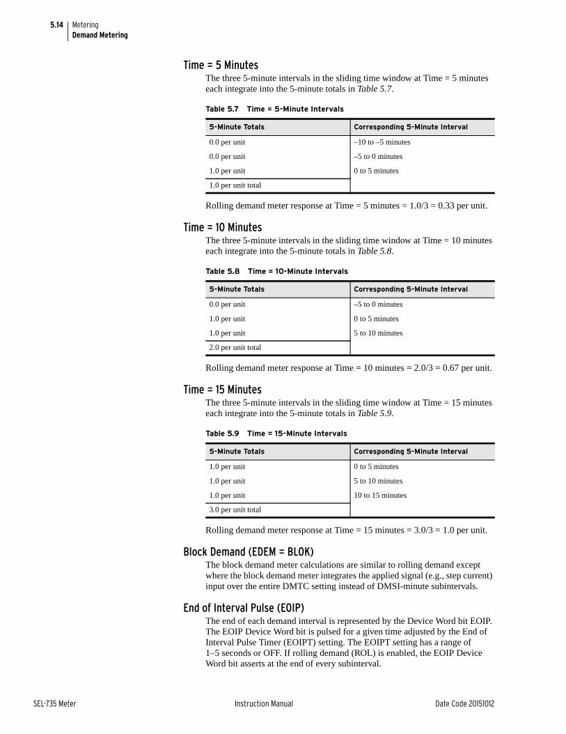
5.14
SEL-735 Meter Instruction Manual Date Code 20151012
MeteringDemand Metering
Time = 5 MinutesThe three 5-minute intervals in the sliding time window at Time = 5 minutes each integrate into the 5-minute totals in Table 5.7.
Rolling demand meter response at Time = 5 minutes = 1.0/3 = 0.33 per unit.
Time = 10 MinutesThe three 5-minute intervals in the sliding time window at Time = 10 minutes each integrate into the 5-minute totals in Table 5.8.
Rolling demand meter response at Time = 10 minutes = 2.0/3 = 0.67 per unit.
Time = 15 MinutesThe three 5-minute intervals in the sliding time window at Time = 15 minutes each integrate into the 5-minute totals in Table 5.9.
Rolling demand meter response at Time = 15 minutes = 3.0/3 = 1.0 per unit.
Block Demand (EDEM = BLOK)The block demand meter calculations are similar to rolling demand except where the block demand meter integrates the applied signal (e.g., step current) input over the entire DMTC setting instead of DMSI-minute subintervals.
End of Interval Pulse (EOIP)The end of each demand interval is represented by the Device Word bit EOIP. The EOIP Device Word bit is pulsed for a given time adjusted by the End of Interval Pulse Timer (EOIPT) setting. The EOIPT setting has a range of 1–5 seconds or OFF. If rolling demand (ROL) is enabled, the EOIP Device Word bit asserts at the end of every subinterval.
Table 5.7 Time = 5-Minute Intervals
5-Minute Totals Corresponding 5-Minute Interval
0.0 per unit –10 to –5 minutes
0.0 per unit –5 to 0 minutes
1.0 per unit 0 to 5 minutes
1.0 per unit total
Table 5.8 Time = 10-Minute Intervals
5-Minute Totals Corresponding 5-Minute Interval
0.0 per unit –5 to 0 minutes
1.0 per unit 0 to 5 minutes
1.0 per unit 5 to 10 minutes
2.0 per unit total
Table 5.9 Time = 15-Minute Intervals
5-Minute Totals Corresponding 5-Minute Interval
1.0 per unit 0 to 5 minutes
1.0 per unit 5 to 10 minutes
1.0 per unit 10 to 15 minutes
3.0 per unit total

5.15
Date Code 20151012 Instruction Manual SEL-735 Meter
MeteringDemand Metering
Predictive Demand Meter Response (EPRED = Y and EDEM = ROL or BLOK)
The SEL-735 supports the processing of predictive demand of the demand analog quantities. Predictive demand calculation and updating occur every processing cycle. Equation 5.1 shows the predictive demand calculation.
Equation 5.1
If the predictive demand settings change, predictive demand resets to zero.
If the calculation value is above the PREDAL (predictive demand alarm threshold) setting for approximately three seconds, the meter asserts the PREDAL Device Word bit. When the value drops below the PREDAL level for approximately three seconds, the meter deasserts the PREDAL Device Word bit. Figure 5.8 shows the PREDAL alarm logic.
Figure 5.8 PREDAL Logic
The following examples in this section illustrate demand current.
The SEL-735 applies demand current pickup settings to demand current meter outputs as shown in Figure 5.9. For example, when residual ground demand current IG(DEM) exceeds corresponding demand pickup GDEMP, Device Word bit GDEM asserts to logical 1. Use demand current logic outputs PDEM, NDEM, GDEM, and QDEM to alarm for high loading conditions or imbalance conditions.
where: Avg = Average of input values observed during the demand
intervalTElapsed = Seconds elapsed in the current demand interval
Present = Most recent input valueTRemaining = Seconds remaining in demand interval
DMTC = Demand Metering time constant
PredDemandAvg TElapsed ondssec( ) Present TRemaining ondssec( )• +•
DMTC 60• ----------------------------------------------------------------------------------------------------------------------------------------------=
Execution: every second
Set
Output
seconds
ResetPREDALD(PREDAL Setting —1) = dropout threshold
(PREDAL Setting) = pickup thresholdPREDALP
DeviceWord
Bit
PREDAL
Group SettingsPREDk = value
seconds
Enables
EPRED=Y
enablecalculation
EDEM=BLOK
EDEM=ROL
EPRED = Y
Group Settings
3
3
3
3

5.16
SEL-735 Meter Instruction Manual Date Code 20151012
MeteringDemand Metering
Figure 5.9 Demand Current Logic Outputs
View or Reset Demand Metering InformationVia ACSELERATOR QuickSet HMI
The ACSELERATOR QuickSet® SEL-5030 Software HMI can display and reset present and peak demand metering. Table 5.10 shows the demand values available through the ACSELERATOR QuickSet HMI.
Demand CurrentPickup Settings(A secondary)
Serial PortCommand
MET RD
QDEMPQDEM
GDEMPGDEMIG(DEM)
IN(DEM)
3I2(DEM)
IC(DEM)
IB(DEM)
IA(DEM)
NDEMPNDEM
PDEM
DemandCurrents
PDEMP
max.phase
demandcurrent
(residual)
resetdemand
resetdemand
resetdemand
resetdemand
IA
IN
IG
3I2
DeviceWordBits
Demand Function
Thermal (EDEM = THM)or
Rolling (EDEM = ROL)or
Block (EDEM = BLOK)
Demand Function
Thermal (EDEM = THM)or
Rolling (EDEM = ROL)or
Block (EDEM = BLOK)
Demand Function
Thermal (EDEM = THM)or
Rolling (EDEM = ROL)or
Block (EDEM = BLOK)
Demand Function
Thermal (EDEM = THM)or
Rolling (EDEM = ROL)or
Block (EDEM = BLOK)
InstantaneousCurrents
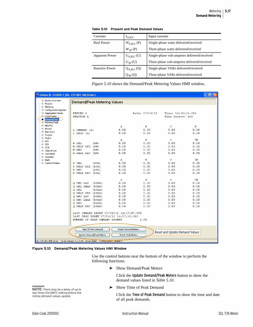
5.17
Date Code 20151012 Instruction Manual SEL-735 Meter
MeteringDemand Metering
Figure 5.10 shows the Demand/Peak Metering Values HMI window.
Figure 5.10 Demand/Peak Metering Values HMI Window
Use the control buttons near the bottom of the window to perform the following functions.
➤ Show Demand/Peak Meters
Click the Update Demand/Peak Meters button to show the demand values listed in Table 5.10.
➤ Show Time of Peak Demand
Click the Time of Peak Demand button to show the time and date of all peak demands.
Table 5.10 Present and Peak Demand Values
Currents IA,B,C Input currents
Real Power WA,B,C (P) Single-phase watts delivered/received
W3P (P) Three-phase watts delivered/received
Apparent Power UA,B,C (U) Single-phase volt-amperes delivered/received
U3P (U) Three-phase volt-amperes delivered/received
Reactive Power QA,B,C (Q) Single-phase VARs delivered/received
Q3P (Q) Three-phase VARs delivered/received
Reset and Update Demand Values
NOTE: There may be a delay of up to two times the DMTC setting before the rolling demand values update.

5.18
SEL-735 Meter Instruction Manual Date Code 20151012
MeteringDemand Metering
➤ Reset Demand Meters
Click the Reset Demand Meters button to reset all Demand values and record the time and date of reset.
➤ Reset Peak Meters
Click the Reset Peak Meters button to reset all Peak Demand values and record the time and date of reset.
Via Front PanelUse the front-panel menu pushbuttons to perform the following functions.
Show Demand and Peak Demand Data
Step 1. Press ENT.
Step 2. Select METER and press ENT.
Step 3. Select one of the following options to perform the associated function.
Step 4. Press ENT.
Step 5. Scroll up and down to view the quantity you want.
Reset Demand Meters
Step 1. Press ENT.
Step 2. Select METER and press ENT.
Step 3. Select one of the following options to perform the associated function.
Step 4. Press ENT.
Step 5. Enter a valid password.
Step 6. When prompted to Reset Demand/Peak Data, select Yes and press ENT.
The SEL-735 displays Reset Complete upon a successful reset.
Step 7. Press ESC to exit the front-panel menu.
Option Associated Function
Display Demand Display demand values
Last Demand Reset Display time and date of last demand reset
Display Peak Display peak demand values
Last Peak Reset Display time and date of last peak demand reset
Previous Peak Display the previous peak demand values
Peak Demand Resets Display the number of peak demand resets
Option Associated Function
Reset Demand Reset all demand values and record the time and date of reset 2AC access is required.
Reset Peak Reset all peak demand values and record the time and date of reset EAC access is required.

5.19
Date Code 20151012 Instruction Manual SEL-735 Meter
MeteringTime-of-Use (TOU)
Via Remote Bits and DNPThree settings allow configuration of remote bits to reset demand, peak demand, or energy values in the SEL-735. Add a remote bit, RB01–RB16, to the global settings RSTDEM, RSTPKDM, or RSTENGY to remotely reset each value. A DNP master can now write a binary output corresponding to a remote bit to reset values in the SEL-735. Optionally, add a remote analog quantity, RA00–RA31, as a password.
For example, set setting RSTPLDM as follows.
RSTPKDM := RB01 AND RA00 = 12345
Now, to reset the peak demand value in the SEL-735, the DNP master writes a value of 12345 to RA00 and asserts RB01 to force the SEL-735 to reset the peak demand value. After resetting the value, the master should write a new value to RA00 to clear the password.
Demand Metering Updating and StorageShould the meter lose control power, it will restore the peak demand values the meter saved during the last save to nonvolatile memory.
To avoid influencing the demand metering peak recording for a system fault, peak recording is momentarily suspended when Device Word bit FAULT is asserted (= logical 1). See the explanation for the FAULT setting in Minimum/Maximum Metering on page 5.36.
Time-of-Use (TOU)To program the SEL-735 for TOU metering, use ACSELERATOR QuickSet to create a TOU program. A TOU program defines the Calendar, Season Schedule, and Rate Schedule the TOU function uses.
To create a TOU program, read the existing settings from the meter and make the necessary settings changes. You can also use ACSELERATOR QuickSet to create new settings. The following pages describe TOU setup through use of ACSELERATOR QuickSet.
After you create the TOU program, use ACSELERATOR QuickSet to send the TOU settings.
TOU SetupThe dialog box shown in Figure 5.11 enables TOU and establishes TOU configuration for the SEL-735.

5.20
SEL-735 Meter Instruction Manual Date Code 20151012
MeteringTOU Setup
Setup Tab
Figure 5.11 Setup Page
Time-of-Use EnabledTime-of-Use Enabled enables or disables TOU metering. Until you enable TOU, other TOU settings are unavailable.
Total CalculationUse Total Calculation to set the method the meter uses to calculate Total Energy. The options are as follows.
➤ Delivered Energy/Demand
➤ Received Energy/Demand
➤ Sum Delivered and Received Energy/Demand
➤ Subtract Received from Delivered Energy/Demand
Self-Read OptionsSelect Perform Self-Read On Manual Peak Demand Reset if you want the meter to perform a self-read when you issue a demand reset from the front panel.
Select Perform Self-Read After Manual Peak Demand Reset when you want the meter to perform a self-read a specified number of days after a demand reset. You must specify the number of days.
Available SeasonsSelect Available Seasons to set the number of seasons available for use in the TOU calendar.
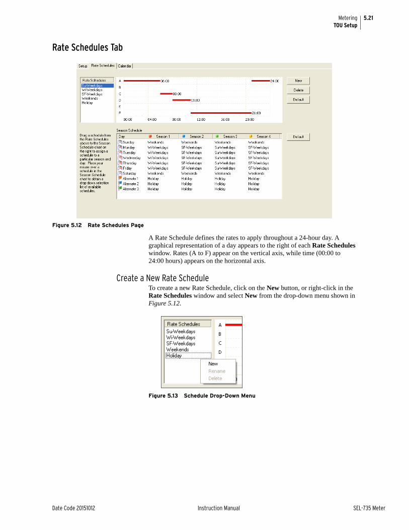
5.21
Date Code 20151012 Instruction Manual SEL-735 Meter
MeteringTOU Setup
Rate Schedules Tab
Figure 5.12 Rate Schedules Page
A Rate Schedule defines the rates to apply throughout a 24-hour day. A graphical representation of a day appears to the right of each Rate Schedules window. Rates (A to F) appear on the vertical axis, while time (00:00 to 24:00 hours) appears on the horizontal axis.
Create a New Rate ScheduleTo create a new Rate Schedule, click on the New button, or right-click in the Rate Schedules window and select New from the drop-down menu shown in Figure 5.12.
Figure 5.13 Schedule Drop-Down Menu

5.22
SEL-735 Meter Instruction Manual Date Code 20151012
MeteringTOU Setup
Delete a Rate Schedule
Figure 5.14 Deleting a Rate Schedule
Step 1. Highlight in the Rate Schedules list the schedule you want to delete.
Step 2. Click the Delete button or right-click and select Delete.
Rename a Rate ScheduleYou can rename a schedule by selecting it from the Rate Schedules list. Right-click on the schedule you want to change, select Rename from the menu, and type in the new name. User-defined names are limited to 20 characters.
Figure 5.15 Renaming a Rate Schedule
Step 1. Select the Rate Schedule in the list of schedules.
Step 2. Right-click and select Rename.
Modify a Rate ScheduleMake assignments to a schedule by highlighting the rate schedule you want to change. The selected rate schedule appears as a chart on the right. Double-click (right or left) on the chart (see Figure 5.16) to insert a new rate.
➤ Double-click the left mouse button on the chart to insert a new rate.
➤ Each right-click of the mouse on an existing rate adds 1 minute.
➤ Each left-click of the mouse on an existing rate removes 1 minute.
➤ Keep the right mouse button depressed over an existing rate to expand the rate in 15-minute intervals until the mouse button is released or until you reach the maximum interval limit.
➤ Keep the left mouse button depressed over an existing rate to reduce the rate in 15-minute intervals until the mouse button is released or until the interval disappears.

5.23
Date Code 20151012 Instruction Manual SEL-735 Meter
MeteringTOU Setup
➤ Right-click on a rate interval bar that has an interval of 5 minutes or less to delete that interval.
➤ Keep the left mouse button depressed on the chart location where you want the new rate to begin, drag to the right to specify the length of the rate you want, then release the left mouse button.
Figure 5.16 Modifying a Rate Schedule
Assign a Rate ScheduleOnce you have created all necessary rate schedules, you must assign a specific schedule to each day type. You can use any schedule for any day type, during any season. To assign a rate schedule for an entire season (e.g., Season 1), you can click and drag from the list the schedule you want and drop it onto the name of your chosen season in the season table.
To assign a rate schedule for use on a specific day type during every season (e.g., Saturday), click and drag from the Rate Schedules list the desired rate schedule you want and drop it onto the day you chose in the table.
To assign a rate schedule to a specific day and season, click and drag a rate schedule from the Schedules list and drop it onto the table entry corresponding to the specific day and season. Alternatively, place your mouse over the table entry you want and click the Edit button that appears on the screen. In the drop-down menu that appears, select the rate schedule you want.

5.24
SEL-735 Meter Instruction Manual Date Code 20151012
MeteringTOU Setup
Calendar Tab
Figure 5.17 Calendar Page
Each entry instructs the TOU program to perform a specific action on that day, such as defining the beginning and ending of seasons or assigning alternate days (e.g., holidays), self-read days, and demand reset days for that year.
Season changes, day type changes, self-reads, and demand resets execute at 00:00.001 on the day you specified. Self-reads occur before demand resets.
Add an Action to the CalendarTo add an action to the calendar, use the Display Year menu to select the year you want to edit. Click and drag an action (Season Changes, Alternates, Self Read, Demand Reset, or Daylight Saving) from the top of the page, and drop the action icon onto the calendar date. You can also right-click on a calendar date and select New from the drop-down menu shown in Figure 5.18. The Calendar Entry Editor will appear as in Figure 5.19. Select the action you want and determine how you want this action to repeat.

5.25
Date Code 20151012 Instruction Manual SEL-735 Meter
MeteringTOU Setup
Figure 5.18 Calendar Entry Drop-Down Menu
Figure 5.19 Calendar Entry Editor
Moving an Action on the CalendarDrag the action icon from one day to another. Drop the action icon on the day for which you want the action to occur.
Delete an Action from the CalendarSelect and drag an action icon off the calendar or into the recycle bin at the top of the form.
Edit an Action on the Calendar
Figure 5.20 Calendar Entry Editor
Step 1. Double-click on the calendar entry for the action you want to change.
Step 2. Right-click on the calendar entry you want to change, and select Edit.
Step 3. Left-click on a Configure button to modify date patterns.

5.26
SEL-735 Meter Instruction Manual Date Code 20151012
MeteringTOU Setup
Establish Quick Set Defaults
Figure 5.21 Quick Set Menu
Use the Quick Set options to return common TOU settings to factory defaults. To use a Quick Set option, perform the following.
Step 1. Right-click on the calendar, and select the Quick Set menu option.
Step 2. Select the appropriate item from the Quick Set submenu (see Figure 5.21).
Step 3. Click Yes when prompted.
TOU Register Data Click on the Human Machine Interface icon and select Time-of-Use from the HMI tree view to view all TOU register data. Use the Time-of-Use Registers drop-down menu to select the season data you want to view. The SEL-735 displays data in bar graph and text formats (see Figure 5.22).
Figure 5.22 TOU Data Page

5.27
Date Code 20151012 Instruction Manual SEL-735 Meter
MeteringTOU Setup
TOU RegistersChoose which block of TOU registers you want to view. These blocks, available from the drop-down list, are as follows.
Present SeasonThis first block (the default) is for presently accumulated season data since the last season change.
Previous SeasonThis block provides data accumulated throughout the previous season.
Self-ReadsThere are 15 pairs of TOU register blocks that operate in the following manner.
➤ The self-read block provides TOU registers for the season in which the self-read occurs and shows accumulated data from the time of the last season change to the time of the self-read.
➤ The previous self-read block provides TOU registers for data accumulated throughout the previous season.
Data Export Use the Export button to create an Excel spreadsheet containing TOU register data and program-setting information.
Billing Data Access to TOU billing data is available on any communications port. Refer to Appendix E: Modbus Communications Protocol for more information on using the Modbus protocol to access TOU data. TOU billing data are also used as display points in the rotating display or for viewing from the front-panel main menu via the front-panel HMI. Refer to Section 3: Front-Panel Operation for information on front-panel setup and use.
Appendix G: Analog Quantities and Device Word Bits lists all TOU billing quantities available in the SEL-735 and describes their usage.
Table 5.11 Available Time-of-Use Data (Sheet 1 of 3)
Rated Energy Block
Rate X MWH “Total”a
Rate X VARH “Total”a
Rate X VAH “Total”a
Rate X WH Receiveda
Rate X VARH Receiveda
Rate X UH Receiveda
Total WH Received
Total URH Received
WH “Total” at Demand Reset
WH “Total” since Demand Reset
UH “Total” at Demand Reset
UH “Total” since Demand Reset
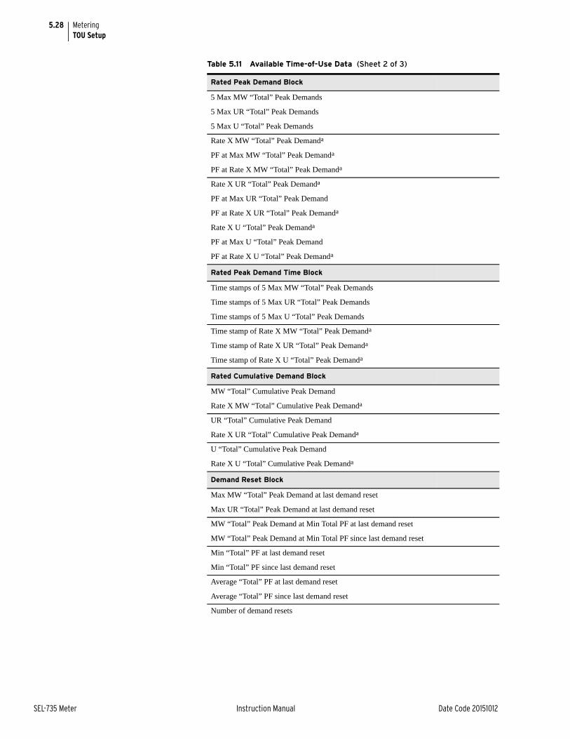
5.28
SEL-735 Meter Instruction Manual Date Code 20151012
MeteringTOU Setup
Rated Peak Demand Block
5 Max MW “Total” Peak Demands
5 Max UR “Total” Peak Demands
5 Max U “Total” Peak Demands
Rate X MW “Total” Peak Demanda
PF at Max MW “Total” Peak Demanda
PF at Rate X MW “Total” Peak Demanda
Rate X UR “Total” Peak Demanda
PF at Max UR “Total” Peak Demand
PF at Rate X UR “Total” Peak Demanda
Rate X U “Total” Peak Demanda
PF at Max U “Total” Peak Demand
PF at Rate X U “Total” Peak Demanda
Rated Peak Demand Time Block
Time stamps of 5 Max MW “Total” Peak Demands
Time stamps of 5 Max UR “Total” Peak Demands
Time stamps of 5 Max U “Total” Peak Demands
Time stamp of Rate X MW “Total” Peak Demanda
Time stamp of Rate X UR “Total” Peak Demanda
Time stamp of Rate X U “Total” Peak Demanda
Rated Cumulative Demand Block
MW “Total” Cumulative Peak Demand
Rate X MW “Total” Cumulative Peak Demanda
UR “Total” Cumulative Peak Demand
Rate X UR “Total” Cumulative Peak Demanda
U “Total” Cumulative Peak Demand
Rate X U “Total” Cumulative Peak Demanda
Demand Reset Block
Max MW “Total” Peak Demand at last demand reset
Max UR “Total” Peak Demand at last demand reset
MW “Total” Peak Demand at Min Total PF at last demand reset
MW “Total” Peak Demand at Min Total PF since last demand reset
Min “Total” PF at last demand reset
Min “Total” PF since last demand reset
Average “Total” PF at last demand reset
Average “Total” PF since last demand reset
Number of demand resets
Table 5.11 Available Time-of-Use Data (Sheet 2 of 3)

5.29
Date Code 20151012 Instruction Manual SEL-735 Meter
MeteringTOU Glossary
TOU GlossaryTOU Register Data Contains all registers included in a Rate X register set for each of the rates you
have defined. These are the data necessary to produce a bill for the consumer.
Cumulative Demand The sum of the peak demand readings after each demand reset during the same billing period. At each demand reset, the meter adds the peak demand from the most recent billing period to the previously accumulated total of all peak demands.
Day Type A day (24 hours) that has a specific rate assigned for each season through the Rate-Schedule table. Day types are Monday, Tuesday, Wednesday, Thursday, Friday, Saturday, Sunday, Alternate 1, Alternate 2, and Alternate 3. These represent the typical days of the week and three alternate days for holidays or special occasions.
Five Maximum MW/UR/U “Total” Demands
The five maximum megawatt/VAR/volt-ampere demand values recorded since the last demand reset. The values are nonrated and are listed from highest to lowest. The meter uses the Total Calculation setting to calculate these registers, and includes time stamps for each of the five maximum demands. The maximum demand includes the coincident power factor.
WH/MVAH Total At/Since Demand Reset
Each demand reset resets to zero the values the meter has collected since the previous demand reset (see Figure 5.23).
Figure 5.23 Total At/Since Demand Reset
Demand Reset Timestamp Block
Times tamp of Max MW “Total” Peak Demand at last demand reset
Time stamp of Max UR “Total” Peak Demand at last demand reset
Time stamp of Min “Total” PF at last demand reset
Time stamp of Min “Total” PF since last demand reset
Time stamp of last demand reset
a X = A–F.
Table 5.11 Available Time-of-Use Data (Sheet 3 of 3)
MWH Total at Demand Reset
MWH Total Since Demand ResetPresentTime
DemandReset
DemandReset
DemandReset
Time
MWH

5.30
SEL-735 Meter Instruction Manual Date Code 20151012
MeteringTOU Glossary
MW/MVAR “Total” Cumulative Demand
The sum of the peak demand between each demand reset without regard to rate (see Figure 5.24).
Figure 5.24 Peak Cumulative Demand
Rate X MW/MVAR “Total” Cumulative Demand
Where X = A–F. Similar to the definition for MW/MVAR “Total” Cumulative Demand, except that the meter sums peaks according to rate.
Rate Schedule A schedule spanning one day (24 hours) that specifies the Rate X register set into which the meter records energy and maximum demand data. For example, the meter records data from midnight until 07:59 into Rate A registers. The meter will record data in this manner until midnight, when the rate schedule for the following day applies.
Rate X WH, MVARH, MVAH Received
Where X = A–F. The number of received megawatt/VAR/volt-ampere hours the meter records during periods defined for a given day type within a given season. These values constitute received quantities only.
Rate X WH, MVARH, MVAH “Total”
Where X = A–F. The number of megawatt/VAR/volt-ampere hours the meter records during periods defined for a given day type within a season. The meter uses the Total Calculation setting to calculate these registers.
Rate X MW/MVAR/MVA “Total” Peak Demand
Where X = A–F. The peak total demand recorded at each rate since the last demand reset.
The meter uses the Total Calculation setting to calculate these registers, and includes time stamps and coincident power factors.
Rated Demand or Energy
The value that the TOU program in the SEL-735 stores for each rate schedule defined in the ACSELERATOR QuickSet Time-Of-Use setting window.
Season A consecutive period delimited by one-day boundaries such as January 1–March 31. You must define one or more seasons that span an entire calendar year and specify which rate schedule applies to each day type. The seasons typically repeat for each year of the 20-year calendar. Use the TOU calendar to specify seasons.
Peak Demand 1
Peak Demand 2
PresentTime
DemandReset 1
DemandReset 2
Time
Cumulative Demand = Peak Demand 1 + Peak Demand 2

5.31
Date Code 20151012 Instruction Manual SEL-735 Meter
MeteringEnergy Metering
Self-Read The SEL-735 copies and stores the present values in demand and energy registers.
Total Calculation The meter calculates a total energy value according to the following Total Calculation setting options.
➤ Delivered
➤ Received
➤ Delivered + Received
➤ Delivered – Received
Total WH, MVARH Received
The total number of received MWH/MVAR hours recorded during this season. These energy values are unrated registers, accumulated without regard to rate.
Energy MeteringEnergy Calculations The SEL-735 calculates energy by integrating power over time. This is
accomplished through the use of a numerical approximation of the integral. As an example, using active power, P, as described previously, the SEL-735 calculates watthours by adding watthours for the most recent interval to the previously accumulated watthour value.
Equation 5.2
In the previous example, P can be a per-phase or polyphase quantity. Separate registers are available for bidirectional and four-quadrant energy metering. These calculations use a similar algorithm for reactive and apparent power.
Scaling
Load Profile RecorderThe SEL-735 configures Load Profile Recorder 1 as the billing recorder, with fixed scaling to ensure compatibility with Itron® MV-90 and other meter- reading software. Table 5.12 lists the scaling differences between fixed scaling Recorder 1 and configurable scaling for recorders 2–12.
where:P = the active power measured over the time interval Δtn = the index for the most recent, nonoverlapping interval Δt
Wh(n–1) = the accumulated energy from all prior intervalsΔt = the time interval in seconds, normally 10/12 cycles
Wh n( )xP Δt• 3600
--------------- Wh n 1–( )x+=

5.32
SEL-735 Meter Instruction Manual Date Code 20151012
MeteringEnergy Metering
Energy data in the billing recorder report as the change-over-interval from the beginning to the end of the interval. These data comprise the consumed energy during each LDP interval.
When energy data are in the PQ recorders and you have set the recorder function to End-of-Interval, then energy data roll over at nine dials. For example, if energy is 9,999,999.99 Wh, an increment in energy causes a rollover and a reset of the energy value to 0.00.
If you need different scaling, create a configurable register in the load profile recorder.
Fast Meter MessagesThe SEL-735 reports Fast Meter messages energy data in Mega units that rollover at 999,999,999.
Other InterfacesThe SEL-735 reports energy data on all other interfaces in accordance with the ENRG_SCA and PRI_SCA settings.
Table 5.12 Load Profile Recorder Scaling
Load Profile Recorder Quantity Scaling Applied
1 (Billing Recorder)
Energy Primary, Kilo
Volts and Power Primary, Kilo
Current Primary, Unity
2–12 (PQ Recorders)
Energy PRI_SCA, ENRG_SCA
Power PRI_SCA, POWR_SCA
Volts PRI_SCA, VOLT_SCA
Current PRI_SCA, Unity

5.33
Date Code 20151012 Instruction Manual SEL-735 Meter
MeteringEnergy Metering
View or Reset Energy Metering Information
Via ACSELERATOR Quickset HMIThe ACSELERATOR Quickset HMI displays and controls all energy data. Figure 5.25 shows the Energy Metering Values HMI Window.
Figure 5.25 Energy Metering Values HMI Window
Use the control buttons near the bottom of the window to perform the following functions.
➤ Reset Energy Meter DataClick the Reset Energy Meters button to reset all energy data and record the time and date of reset.
➤ Show Energy Meter DataClick the Update Energy Meters button to show the most recent energy data.
Via Front PanelUse the front-panel menu pushbuttons to perform the following functions.
Show Energy Data
Step 1. Press ENT.
Step 2. Select METER and press ENT.
Step 3. Select Energy and press ENT.
NOTE: Single-phase quantities are available only in Form 9 and Form 36 models.
Reset and Update Energy

5.34
SEL-735 Meter Instruction Manual Date Code 20151012
MeteringEnergy Metering
Step 4. Select one of the following options to perform the associated function.
Step 5. Press ENT.
Reset EnergyStep 1. Press ENT.
Step 2. Select METER and press ENT.
Step 3. Select Energy and press ENT.
Step 4. Select Reset Energy and press ENT.
Step 5. Enter a valid 2AC password.
Step 6. When prompted to Reset Energy Data, select Yes and press ENT.
The SEL-735 displays Reset Complete upon a successful reset.
Step 7. Press ESC to exit the front-panel menu.
Via Remote Bits and DNPSee Via Remote Bits and DNP on page 5.34.
Energy Cut-Off Point As the power factor approaches zero, small phase angle measurement errors result in relatively large errors in real power (watts) measurements. This is because of the sensitivity of the cosine function as the phase angle approaches 90° (PF = 0).
To prevent erroneous real power measurements under near PF = 0 conditions, the SEL-735 uses the ANGCUT setting to support an energy cut-off angle. When the phase angle between the current and voltage reaches the cut-off setting, the meter zeroes rms watts. The ANGCUT setting supports cut-off angles from 1° to 10°.
When the vectors VA and IA have a relative phase angle difference of 0°, only real power (watts) flows through a power system. For example, 120 V • 5 A • Cos(0°) = 600 W.
When the vectors VA and IA have a relative phase angle difference of 90°, only reactive power (VARs) flows through a power system. For example, 120 V • 5 A • Cos(90°) = 0 W = 600 VARS.
In a real power system, and during accuracy testing, the phase angles of the current and voltage will fluctuate slightly. If IA is 90 degrees off from AV, the relative VAR measurement changes little as the IA phase angle fluctuates, but the relative watt measurement will change noticeably. In addition, some of the watts will report as delivered and some of the watts will report as received.
Option Associated Function
Display Energy Display energy data
Last Energy Reset Display time and date of last Energy reset
Display Peak Display peak demand values
Last Peak Reset Display time and date of last peak demand reset
Previous Peak Display the previous peak demand values
Peak Demand Resets Display the number of peak demand resets

5.35
Date Code 20151012 Instruction Manual SEL-735 Meter
MeteringEnergy Metering
The ANGCUT setting prevents the SEL-735 from recording these small watt values when the power factor is close to 0 and prevents VARs from recording when the power factor is close to 1.
Figure 5.26 Power Factor = ±0.02
See Table 5.13 for an example of when the ANGCUT setting affects power and energy calculations.
Preload Energy Values
You can preload the energy values in the meter from 0 to 999,999,999,999.999. Amp-hour and volt-hour quantities are set in unity units, while all other energy values are set in kilo units. When you read settings from an SEL-735, the energy preload settings of the settings file populate with the meter energy values at the time of the read. This simplifies meter swapping, while maintaining the same energy data between the two meters.
Table 5.13 Example ANGCUT Setting
ANGCUT Setting Watts Zeroed Between VARs Zeroed Between
OFF n/a n/a
2 88° to 92° and –88° to –92° 2° to –2° and 178° to –178°
10 80° to 100° and –80° to –100° 10° to –10° and 170° to –170°
IA
VA

5.36
SEL-735 Meter Instruction Manual Date Code 20151012
MeteringMinimum/Maximum Metering
Minimum/Maximum MeteringView or Reset Minimum/Maximum Metering Information
The power maximum and minimum values can be negative or positive, indicating the range of power flow that has occurred since the last Min/Max reset. These functions simulate analog meter drag-hands, with the maximum value representing the upper drag-hand and the minimum value representing the lower drag-hand.
Via ACSELERATOR HMIThe ACSELERATOR Quickset HMI displays and controls all Minimum/Maximum meter data.
Figure 5.27 shows the Min/Max meter data.
Figure 5.27 Min/Max Metering Values HMI Window
Use the control buttons near the bottom of the window to perform the following functions.
➤ Reset Min/Max Meter DataClick the Reset Min/Max Meters button to reset all Min/Max data and record the date and time of reset.
➤ Show Min/Max Meter DataClick the Update Energy Meters button to show the most recent Min/Max data.
Via Front PanelUse the front-panel menu pushbuttons to perform the following functions.
Show Latest Min/Max DataStep 1. Press ENT.
Step 2. Select Meter > Max/Min and press ENT.
Reset and Refresh MIN/MAX Data

5.37
Date Code 20151012 Instruction Manual SEL-735 Meter
MeteringMinimum/Maximum Metering
Step 3. Select one of the following options and press ENT.
Step 4. Scroll up and down to view the quantity you want.
Reset Min/Max DataStep 1. Press ENT.
Step 2. Select Meter > Max/Min and press ENT.
Step 3. Select Reset Max/Min and press ENT.
Step 4. Enter a valid 2AC password.
Step 5. When prompted to Reset Min/Max Data, select Yes and press ENT.
The SEL-735 displays Reset Complete upon a successful reset.
Step 6. Press ESC to exit the front-panel menu.
Minimum/Maximum Metering Update and Storage
The minimum/maximum metering function is intended to reflect normal load variations rather than fault conditions or outages. Therefore, maximum/ minimum values update only if the following conditions are met.
➤ DFAULT is deasserted (= logical 0).
➤ The metering value is above the previous maximum or below the previous minimum for two 10/12 cycle intervals.
Figure 5.28 FAULT and DFAULT Device Word Bit Logic
The meter saves minimum/maximum values to nonvolatile memory once every minute and overwrites the previous stored value if it is exceeded. Should the meter lose control power, it will restore the minimum/maximum values saved by the meter during the last save to nonvolatile memory.
Fault Detection The SEL-735 will not meter certain values during faults, to ensure that it records only billable quantities. When asserted, the overcurrent elements ensure that the meter does not record peak demand, maximum metering, energy, and crest factors.
Option Associated Function
Display Max/Min Display most recent Max/Min data
Last Max/Min Reset Display time and date of last Max/Min rest
060sec
FAULT
DFAULT
10
DeviceWordBits
24
I1k
I1(k-16)
|I1k| - |I1(k-16)|
SELOGIC Control Equation: FLTBLK
NOTE: Device Word bit FAULT and DFAULT also control other meter functions.
NOTE: The minimum/maximum metering function updates every second. These values are relatively immune to transient conditions.

5.38
SEL-735 Meter Instruction Manual Date Code 20151012
MeteringCrest Factor Metering
ElementsFAULT: Device Word bit that asserts if the positive-sequence current exceeds 24 A (6.3 A for CL2) or the metered current rises 10 A between any two power system cycles. Figure 5.28 illustrates when the FAULT and DFAULT bits assert. Peak demand, minimum/maximum metering, energy, and crest factor metering cease when the FAULT Device Word bit is asserted (logical 1).
DFAULT, Delayed Fault: Device Word bit that asserts identically to the FAULT bit and suspends the same metering values. The DFAULT Device Word bit remains asserted for 60 seconds after removal of the fault condition.
FLTBLK, Fault Bit Block SELOGIC® control equation: SELOGIC control equation setting FLTBLK (Fault block) must be deasserted (logical 0) for the FAULT Device Word bit to assert during a fault on the system. Configure FLTBLK to override, when asserted, the FAULT Device Word bit. The default setting for FLTBLK is deasserted.
Crest Factor MeteringAlong with total harmonic distortion, crest factor is an indication of power quality. A sinusoidal waveform crest factor is 1.414, and a square wave crest factor is 1.0. The SEL-735 records the maximum and minimum crest factor metering values.
The SEL-735 uses the equation shown in Equation 5.3 to calculate crest factor values.
Equation 5.3
View or Reset Crest Factor Metering Information
Via ACSELERATOR HMIThe ACSELERATOR Quickset HMI displays and controls all crest factor data. Figure 5.29 shows the crest factor data as viewed from the ACSELERATOR QuickSet HMI.
Figure 5.29 Crest Factor Metering Values HMI Window
Crest FactorPeak Valuerms Value---------------------------=
Reset and Refresh Crest Factor Data

5.39
Date Code 20151012 Instruction Manual SEL-735 Meter
MeteringHarmonic Metering
Use the control buttons near the bottom of the window to perform the following functions.
➤ Reset Crest Factor DataClick the Reset Crest Factor Meters button to reset all crest factor data and record the date and time of reset.
➤ Show Crest Factor DataClick the Update Crest Factor Meters button to show the most recent crest factor data.
Crest Factor Metering Update and Storage
The crest factor metering function reflects normal load variations, rather than fault conditions or outages. Therefore, crest factor values only update if the following conditions are met.
➤ DFAULT is deasserted (= logical 0).
➤ For Form 9 and Form 36 voltage values VA,B,C or Form 5 voltage values VAB,BC,CA, the voltage is above the corresponding 25.0 V secondary threshold.
➤ For current values IA,B,C,N, the current is above the corresponding 105 mA secondary threshold.
➤ The metering value is above the previous maximum or below the previous minimum for two 10/12 cycles.
The SEL-735 stores crest factor values into nonvolatile memory every minute.
Harmonic MeteringThe SEL-735 provides harmonic measurements for the following values.
➤ Harmonic magnitudes for voltage, current, and power
➤ Percent of fundamental harmonic magnitudes for voltage and current
➤ SELOGIC voltage and current harmonic threshold alarms for the 2nd harmonic order to the 15th harmonic order
➤ Harmonic measurement to the 63rd harmonic order (optional feature)
➤ Harmonic voltage and current angles (optional feature)
➤ Harmonic power (optional feature)
➤ Interharmonic measurement (optional feature)
Harmonic Components and Harmonic Groups
The SEL-735 supports component harmonics and harmonic groups as defined by IEC 61000-4-7:2009-2010 and the following.
DefinitionsHarmonic Component: Rms value of one of the components having a
harmonic frequency in the analysis of a nonsinusoidal waveform.
Harmonic Group: Square root of the sum of squares of the rms value of a harmonic and the spectral components adjacent to it within the time window. Please refer to IEC 61000-4-7:2002-08 for further explanation of harmonic group calculations.

5.40
SEL-735 Meter Instruction Manual Date Code 20151012
MeteringHarmonic Metering
ExplanationThe Include Interharmonics Quantities (INCIHQ) setting determines if harmonic values report according to the Harmonic Group definition or the Harmonic Component definition.
If the INCIHQ setting is Y, harmonic magnitudes report in accordance with the Harmonic Group definition. The meter uses all frequencies in a 50 Hz or 60 Hz window centered on the integer harmonic frequency in the harmonic calculation.
If the INCIHQ setting is N, harmonic magnitudes report in accordance with the Harmonic Component definition. The meter uses only the harmonic frequency in the harmonic calculation.
For example, in a 60 Hz system, the meter will report the third harmonic (180 Hz) inclusive of frequencies from 150 Hz to 210 Hz when INCIHQ is set to Y. Figure 5.30 exemplifies a harmonic report with and without interharmonic frequencies with the INCIHQ setting equal to Y and N.
Harmonic Metering in Form 36 Meters
Because Phase-B voltage is not measured in Form 36 metering, the Phase-B harmonic quantities are not fully representative of the actual harmonics on the system. Any harmonic quantity associated with Phase-B voltage is only a result of a mathematical computation based on Phase-A and Phase-C voltages. Further, any harmonic quantity that mathematically uses the Phase-B voltage harmonic quantity should not be considered to reflect actual system conditions (i.e., three-phase distortion power ratio and three-phase harmonic power).
Harmonic Percentage The meter converts the 2nd to 15th harmonics into a percentage of the fundamental.
If the voltage or current harmonic is below the minimum threshold, the meter reports zero for that particular harmonic percentage.
The HARMTRIG setting determines whether HARM02–HARM15 are triggered on voltage and/or current harmonics. Set HARMTRIG to ALL to trigger on both voltage and current, to VOLTAGE to trigger on voltage only, or to CURRENT to trigger on current-only harmonics. If the threshold is enabled and the harmonic is above the set threshold, then the respective harmonic Device Word bit (HARM02–HARM15) asserts and also latches the PQALARM word bit. The bit deasserts when the respective harmonic falls below the set threshold. Harmonics for currents and voltages are calculated on a per-phase basis; any single-phase harmonic value asserts the HARM02–HARM15 Device Word bits. If any harmonic Device Word bit is set, then the FALARM Device Word bit is set.
Surpassing the given harmonic threshold causes the meter Device Word bit to assert (logical 1).
Table 5.14 Minimum Required Magnitudes for Harmonic Percentage Calculations
Harmonic Quantity Minimum Required Magnitude
Voltage 3.0 VRMS
Current 3 mARMSNOTE: When the SEL-735 is set up as a Form 36 meter, the Phase-B voltage is calculated, not measured. The harmonic quantities reported for Phase B are a result of calculations and should not be considered to reflect actual system conditions. Therefore, the SEL-735 will not include any Phase-B harmonic quantities in the calculation of harmonic triggering. The calculated harmonics reported on Phase B will not cause HARMTRIG to assert.

5.41
Date Code 20151012 Instruction Manual SEL-735 Meter
MeteringHarmonic Metering
EXAMPLE 5.1 Harmonic Alarm Example
Suppose you notice that approximately once a month the system experiences a power failure. You believe the cause is the starting of some large loads that induced harmonics into the system, but this was not verified. With the SEL-735, you made the following settings.
SET HARM02 = 10HARM03 = 10
•••
HARM07 = 10SET L OUT101 = HARM02 OR HARM03 OR HARM04 OR HARM05 OR HARM06 OR HARM07SET R SER1 = HARM02, HARM03, HARM04, HARM05, HARM06, HARM07
You then can monitor OUT101 via the SCADA system and notice that every time the certain load starts, the 3rd harmonic generates significant levels.
Harmonic Magnitudes and Angles
The harmonic magnitude calculations are in accordance with the Harmonic Component and Harmonic Group definitions, controlled by the INCIHQ setting. All harmonic angles reference VA when the VA magnitude is greater than 13 volts, otherwise harmonic angles reference IA. All harmonic angles have a range of –179.99° to 180.00°.
Each harmonic magnitude and angle has an associated analog quantity (see Appendix G: Analog Quantities and Device Word Bits) that uses the following format.
HRMxx_yyM = Harmonic Magnitude
HRMAxx_yyM = Harmonic Angle
You can use the ACSELERATOR QuickSet HMI to view harmonic magnitudes and angles.
Interharmonic Magnitudes
Advanced power quality meters calculate interharmonic magnitudes up to the 63rd harmonic. The ACSELERATOR QuickSet HMI displays individual interharmonic magnitudes, with text and graphical views up to the 63rd harmonic.
where:xx = the harmonic number (2–50 or 2–15)yy = the specific current or voltage phase (IA, IB, IC, IN, VA, VB, or VB

5.42
SEL-735 Meter Instruction Manual Date Code 20151012
MeteringHarmonic Metering
Figure 5.30 Interharmonics vs. Integer-Harmonics Example
K-Factor Calculation Another use for harmonic metering is to prevent transformer overheating as a result of harmonics. The meter calculates K-factor on a per-phase and three-phase basis for use in the detection and monitoring of harmonics. The meter uses the following equation to calculate K-factor for each phase current channel.
Equation 5.4
You can use the ACSELERATOR QuickSet HMI or the front-panel LCD to display K-Factor data.
Distortion Power The meter calculates distortion power as the ratio of average power to fundamental power and reports this power in a percentage. The calculation is on a per-phase and three-phase basis for wye-connected systems and on a three-phase basis only for delta-connected systems. The meter calculates distortion power as follows.
Interharmonics 65—115 Hz
60 Hz Fundamental Harmonic Component
Second HarmonicComponent
where:x = the channel (A, B, C)h = the harmonic number (1 to 25)
K-FACTOR_x
Ixh2 h
2
h=1
25
Ixh2
h=1
25
---------------------=

5.43
Date Code 20151012 Instruction Manual SEL-735 Meter
MeteringHarmonic Metering
Equation 5.5
You can use the ACSELERATOR QuickSet HMI or the front-panel LCD to display distortion power data.
Total Harmonic Distortion (THD)
The meter calculates THD as the ratio of the rms value of the sum of harmonic components (to the specified order) to the rms value of the fundamental component.
The meter calculates THD per phase as follows.
Equation 5.6
Group Total Harmonic Distortion (THDG)
Group total harmonic distortion is very similar to THD, except the calculation uses harmonic groups instead of harmonic components.
The meter calculates THDG as the ratio of the rms value of the sum of harmonic groups (to the specified order) to the rms value of the fundamental component.
The meter calculates THDG per phase as follows.
Equation 5.7
The ACSELERATOR QuickSet HMI software displays THD and THDG data.
where:Dx = the distortion power ratio for the respective phase
Px_avg = the average power for the respective phasePx = the fundamental power for the respective phase
DxPx_avg
Px------------------ 1– 100=
where:X = the appropriate channel IA, IB, IC, VA, VB, VC, etc.ht = the total number of harmonics (15 or 63, based on meter class)
HXn = the harmonic value of the respective harmonicHX1 = the harmonic value of the fundamental frequency
n = the harmonic number
THDX
ht
n=2 HX2n
HX1---------------------------------
100=
where:X = the appropriate channel IA, IB, IC, VA, VB, VC, etc.ht = the total number of harmonics (15 or 63, based on meter
class)HXgn = the harmonic group value of the respective harmonica
a Refer to IEC 61000-4-7:2002—2008 for THDG calculations.
HXg1 = the harmonic group value of the fundamental frequencyn = the harmonic number
THDGX
ht
n=2 HXgn2
HXgl------------------------------------
100=

5.44
SEL-735 Meter Instruction Manual Date Code 20151012
MeteringHarmonic Metering
View Harmonic Data via ACSELERATOR
QuickSet HMI
Use the following guidelines to view harmonic data via the ACSELERATOR QuickSet HMI.
➤ View voltage and current harmonic component percentages, THD, THDG, K-factor, and distortion powerClick the Percentages (I, V) button.
➤ View current and voltage harmonic component magnitudesClick the Magnitudes (I, V) button.
➤ View current harmonic component magnitudes and anglesClick the Magnitudes, Angles (I) button.
➤ View voltage harmonic component magnitudes and anglesClick the Magnitudes, Angles (V) button.
➤ View distortion powerClick the Power button.
➤ View interharmonicsClick the Spectral Analysis button.
Figure 5.31 Harmonics HMI Toolbar
View Harmonic Data via the Front-Panel LCD
Use the front-panel LCD to view THD, K-factor, and distortion power following the steps below.
Step 1. Press ENT.
Step 2. Select Meter and press ENT.
Step 3. Select Harmonics and press ENT.
Step 4. Press Up or Down to view the quantity you want.
Harmonic Component Percentages, THD, THDG, K-Factor, and
Distortion Power
Current Harmonic Component Magnitudes and Angles
Distortion Power
Select Even, Odd, or Both Even and Odd Harmonics
Current and Voltage Harmonic Component Magnitudes
Voltage Harmonic Component Magnitudes and Angles
Interharmonics
Import and ExportHarmonic Data
Chart ActiveHarmonic Data

5.45
Date Code 20151012 Instruction Manual SEL-735 Meter
MeteringFlicker Metering
Flicker MeteringLight flicker from incandescent bulbs caused by fluctuation of voltage magnitude can interfere with the human eye, human brain, and sensitive electrical equipment. The SEL-735 calculates short- and long-term flicker values in accordance to IEC 61000-4-15, Edition 2.0 2010-08, Flickermeter and IEC 61000-4-30.
Inputs to the Flickermeter algorithm include the nominal voltage of the system, which may be either 120 V or 230 V. The VBASE setting allows you to configure any nominal meter voltage over a wide range. When the VBASE setting is between 20.00 V and 175.99 V, the SEL-735 calculates flicker based on a 120 V nominal voltage. When the VBASE setting is between 176.00 V and 300.00 V, the SEL-735 calculates flicker based on a 230 V nominal voltage.
View Flicker Data via the ACSELERATOR
QuickSet HMI
Use ACSELERATOR QuickSet HMI to view and reset flicker data. Figure 5.32 shows the flicker window as it displays on the ACSELERATOR QuickSet HMI.
Figure 5.32 Flicker HMI Window
Transformer/Line Loss CompensationUse known system parameters with transformer/line-loss compensation (TLLC) to estimate power transmission and distribution losses. Manual calculations to implement loss compensation in the SEL-735 are unnecessary. Inputs to the meter use given nameplate transformer specifications and line parameters. The meter adds or subtracts the losses based on these inputs and the location of the metering point versus the billing point.
Power delivery from a power supplier to a point of consumption occurs over a network of transmission lines and through transformers. In addition to generating power for customer loads, the power supplier must supply power to
NOTE: When the SEL-735 is set up as a Form 36 meter, the Phase-B voltage is calculated, not measured. The flicker quantities reported for Phase B are a result of calculations, and should not be considered to reflect actual system conditions.
Import and ExportHarmonic Data

5.46
SEL-735 Meter Instruction Manual Date Code 20151012
MeteringTransformer/Line Loss Compensation
overcome transmission system losses. To increase billing precision, the SEL-735 can compensate for these resistive and inductive power transmission losses. Without loss compensation, power suppliers are unable to bill customers for losses that occur before the metering point.
In a basic system, there are four possible billing points and four possible meter points. Figure 5.33 shows the diagram of the billing and metering points. Table 5.15 shows the addition and subtraction of line and transformer loss compensation. The meter uses the transformer constants, T1 and T2, in the line loss calculations and then adds calculated losses to or subtracts these losses from the energy, demand, and power quantities.
When transformer/line-loss compensation is enabled (ETLLC is enabled) power quantities (W, Wh, etc) and reactive power quantities (VAR, VARh, etc) are compensated. For each compensated value, there is an Analog Quantity that always remains uncompensated, as listed in Appendix G: Analog Quantities and Device Word Bits. The names of these analog quantities end in “_UC” and their descriptions specify “uncompensated.”
Voltage, current and apparent power quantities are never compensated.
Figure 5.33 Meter and Billing Positions
Load LineSupply Line
POSITION 2 POSITION 3 POSITION 4
CustomerTransformerUtility
POSITION 1
Table 5.15 Transformer and Line Loss Adjustments
Billing Position (BPOS)
Meter Position (MPOS)
Supply Line Constant, T1a
a XFTR is the main Transformer Turns Ratio setting.
Load Line Constant, T2
Change to Calculated Power
1
1 1 XFTR
No adjustment
2 Supply line losses subtracted
3 Supply line and transformer losses subtracted
4 Transformer, supply line, and load line losses subtracted
1
2 1 XFTR
Supply line losses added
2 No adjustment
3 Transformer losses subtracted
4 Transformer and load line losses subtracted
1
3 1/XFTR 1
Transformer losses and supply line losses added
2 Transformer losses added
3 No adjustment
4 Load side line losses subtracted
1
4 1/XFTR 1
Transformer, supply line, and load line losses added
2 Load line and transformer losses added
3 Load line losses added
4 No adjustment
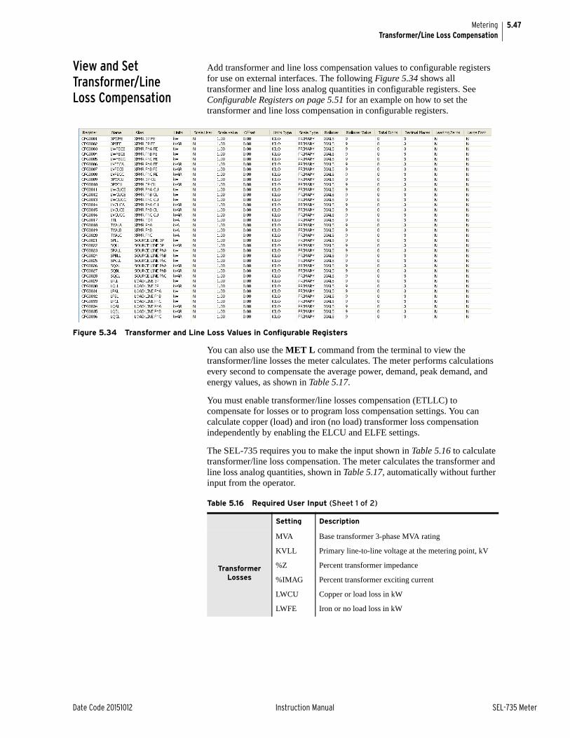
5.47
Date Code 20151012 Instruction Manual SEL-735 Meter
MeteringTransformer/Line Loss Compensation
View and Set Transformer/Line Loss Compensation
Add transformer and line loss compensation values to configurable registers for use on external interfaces. The following Figure 5.34 shows all transformer and line loss analog quantities in configurable registers. See Configurable Registers on page 5.51 for an example on how to set the transformer and line loss compensation in configurable registers.
Figure 5.34 Transformer and Line Loss Values in Configurable Registers
You can also use the MET L command from the terminal to view the transformer/line losses the meter calculates. The meter performs calculations every second to compensate the average power, demand, peak demand, and energy values, as shown in Table 5.17.
You must enable transformer/line losses compensation (ETLLC) to compensate for losses or to program loss compensation settings. You can calculate copper (load) and iron (no load) transformer loss compensation independently by enabling the ELCU and ELFE settings.
The SEL-735 requires you to make the input shown in Table 5.16 to calculate transformer/line loss compensation. The meter calculates the transformer and line loss analog quantities, shown in Table 5.17, automatically without further input from the operator.
Table 5.16 Required User Input (Sheet 1 of 2)
Setting Description
Transformer Losses
MVA Base transformer 3-phase MVA rating
KVLL Primary line-to-line voltage at the metering point, kV
%Z Percent transformer impedance
%IMAG Percent transformer exciting current
LWCU Copper or load loss in kW
LWFE Iron or no load loss in kW

5.48
SEL-735 Meter Instruction Manual Date Code 20151012
MeteringTransformer/Line Loss Compensation
Transformer Loss Calculations
Equation 5.8 and Equation 5.15 show transformer loss calculations. First, the meter uses the settings LWCU, LWFE, %Z, %IMAG, and MVA to calculate the base watt and VA losses. Enter the nameplate watt losses, LWCU and LWFE, in kilowatt units; enter the nameplate impedance values in percent (e.g., enter 8 percent impedance as 8; enter the power transformer rating MVA rating).
Base Copper Loss, MW
Equation 5.8
Base Iron Loss, MW
Equation 5.9
Line Losses
SLR Supply line resistance, ohms primary
SLX Supply line inductive reactance, ohms primary
LLR Load line resistance, ohms primary
LLX Load line inductive reactance, ohms primary
XFTR Power transformer turns ratio
Table 5.17 Analog Quantities: Transformer and Line Losses
Setting Description
Transformer Losses
3PWFE Three-phase active power iron loss, watts
3PVFE Three-phase reactive power iron loss, VARs
LWFECx Individual phase transformer active power iron loss, watts
LVFECx Individual phase transformer reactive power iron loss, VARs
3PWCU Three-phase active power copper loss, watts
3PVCU Three-phase reactive power copper loss, VARs
LWCUCx Individual phase transformer active power copper loss, watts
LVCUCx Individual phase transformer active power copper loss, VARs
TTL Three-phase total transformer loss, VA
TVALx Individual phase transformer loss, VA
Source Line Losses
SPLL Total source line active power loss, watts
SQLL Total source line reactive power loss, VARs
SPxL Individual phase source line active power loss, watts
SQxL Individual phase source line reactive power loss, VARs
Load Line Losses
LPLL Total load line active power loss, watts
LQLL Total load line reactive power loss, VARs
LPxL Individual phase load line active power loss, watts
PQxL Individual phase load line reactive power loss, VARs
Table 5.16 Required User Input (Sheet 2 of 2)
VSupply
VLoad--------------------
LWCUBLWCU1000
-----------------=
LWFEBLWFE1000
-----------------=

5.49
Date Code 20151012 Instruction Manual SEL-735 Meter
MeteringTransformer/Line Loss Compensation
Base Copper Loss, MVA
Equation 5.10
Base Iron Loss, MVA
Equation 5.11
The meter then converts the base watt and VA parameters into base VAR parameters, as shown in Equation 5.12 and Equation 5.13.
Base Copper Losses, MVAR
Equation 5.12
Base Iron Losses, MVAR
Equation 5.13
Next, the meter uses the settings KVLL and MVA as shown in Equation 5.14 and Equation 5.12 to calculate dynamic current and voltage correction factors. The meter uses these dynamic correction factors to proportion the measured current and voltage values in the loss calculations.
Dynamic Current Correction Factor, Per Unit
Equation 5.14
Dynamic Voltage Correction Factor, Per Unit
Equation 5.15
Lastly, the meter uses the values it calculates and the voltage and current values it measures, Ix and Vx, as shown in Equation 5.18–Equation 5.25 (replace x with the respective phase A, B, or C), to calculate the transformer losses incurred. Access the calculated losses in the transformer copper and iron losses analog quantities.
Iron LossesPrimary Iron Losses, MW
Equation 5.16
Primary Iron Losses, MVAR
Equation 5.17
Three-Phase Iron Loss, MW
Equation 5.18
VACUB% Z100---------- MVA• =
VAFEB% IMAG
100----------------------- MVA• =
LVCUB VACUB2
LWCUB2
–=
LVFEB VAFEB2
LWFEB2
–=
DICF3 KVLL•
MVA 1000• ---------------------------------=
DVCF3
KVLL-----------------=
LWFECx LWFEB Vx DVCF• ( )2• =
NOTE: The metering industry has standardized on the principle that reactive iron losses are proportional to the fourth power of the voltage.
LVFECx LVFEB Vx DVCF• ( )4• =
3PWFE LWFECA LWFECB LWFECC+ +=

5.50
SEL-735 Meter Instruction Manual Date Code 20151012
MeteringTransformer/Line Loss Compensation
Three-Phase Iron Loss, MVAR
Equation 5.19
Copper LossesPrimary Copper Losses, MW
Equation 5.20
Primary Copper Losses, MVAR
Equation 5.21
Three-Phase Copper Loss, MW
Equation 5.22
Three-Phase Copper Loss, MVAR
Equation 5.23
Iron and Copper LossesTotal Transformer Loss, MVA
Equation 5.24
Total Per-Phase Transformer Losses, MVA
Equation 5.25
Line Loss Calculations
If you know the conductor resistance and reactance of the supply and load lines, you can program the meter to calculate per-phase line losses. In a three-phase system, the SEL-735 assumes that each conductor has identical impedances and that only series losses are present.
The SEL-735 uses the following equations to calculate supply and load line loss compensation values. The supply and load line constants, T1 and T2, convert the supply and load losses to the metered side of the power transformer, according to Table 5.15.
Supply Line LossSupply Line Watt Losses
Equation 5.26
Supply Line VAR Losses
Equation 5.27
3PVFE LVFECA LVFECB LVFECC+ +=
LWCUCx LWCUB Ix DICF• ( )2• =
LVCUCx LVCUB Ix DICF• ( )2• =
3PWCU LWCUCA LWCUCB LWCUCC+ +=
3PVCU LVCUCA LVCUCB LVCUCC+ +=
TTL 3PWCU 3PWFE+( )23PVCU 3PVFE+( )2
+=
TVALx LWFECx LWCUCx+( )2LVFECx LVCUCx+( )2
+=
SPxL Ix T1• ( )2 SLR
1X10⁶
----------------• =
SQxL Ix T1• ( )2 SLX
1X106
----------------• =

5.51
Date Code 20151012 Instruction Manual SEL-735 Meter
MeteringConfigurable Registers
Total Supply Line Watt Losses
Equation 5.28
Total Supply Line VAR Losses
Equation 5.29
Load-Line LossLoad Line Watt Losses
Equation 5.30
Load Line VAR Losses
Equation 5.31
Total Load Line Watt Losses
Equation 5.32
Total Load Line VAR Losses
Equation 5.33
Configurable RegistersConfigurable registers allow you to control the scaling, formatting, and labeling of metered quantities as these would appear to external interfaces. The registers allow you to present consistently scaled and formatted data among all interfaces.
Attributes Each configurable register contains several user-defined attributes that control the scaling and presentation of the value. Table 5.18 lists available attributes, their default value, and range.
SPLL SPAL SPBL SPCL+ +=
SQLL SQAL SQBL SQCL+ +=
LPxL Ix T2• ( )2 LLR
1X10⁶
----------------• =
LQxL Ix T2• ( )2 LLX
1X106
----------------• =
LPLL LPAL LPBL LPCL+ +=
LQLL LQAL LQBL LQCL+ +=
Table 5.18 Configurable Register Attributes (Sheet 1 of 2)
Attribute DescriptionDefault Value
Range
Register The number of the configurable register. N/A 1–1000
Name The name of the analog quantity. “ “ Analog Quantity
Alias A user-defined text string of the alias to display on external interfaces.
“ “ “a–z”, “A–Z”, “0–9”, <space>, <underscore>
Decimals User-defined number of decimal places to pass to external interfaces.
2 0–6
Leading_Zeros Boolean setting determines if leading zeros are displayed on LCD.
N Y, N
Large_Font Boolean setting determines if the display is in large font on LCD.
Y Y, N

5.52
SEL-735 Meter Instruction Manual Date Code 20151012
MeteringConfigurable Registers
ConfigurationACSELERATOR QuickSet settings software simplifies setup of configurable registers. The Configurable Registers setup window, as shown in Figure 5.35, contains the following four sections: Map, Options, Interfaces, and Operations. The Map section shows configurable registers already configured and their associated attributes. Use the Options section to enter all attributes explained in Table 5.18. View the different result outputs on the Interfaces section. Execute the configurations from the Operations section.
Follow the guidelines and steps that follow to set up a configurable register.
Step 1. Navigate to settings Metering > Configurable Registers in ACSELERATOR QuickSet.
The Configurable Registers setting window displays, similar to Figure 5.35.
Step 2. Enter in the Options section the attributes you want, as explained in Table 5.18.
Step 3. Use the Interfaces section to view how the meter will pass the configurable register result to interfaces.
a. Enter a number in the Interfaces section.
b. Click the Preview button in the Options section.
The different results display in the Interfaces section.
Step 4. Click the Add button in the Operations section to save the configurable register to the map.
Scale User Boolean setting determines if a scale value will be applied N Y, N
Scale Value User-defined scale factor. Scales both primary and secondary configurable register values. For example, if the PTR is 120, the Scale Type is PRIMARY, and the Scale Value is 10, then the SEL-735 scales voltage configurable register values by 1200. In the above example, if the Scale Type is set to second-ary, the SEL-735 scales the configurable register value by 10 (the Scale Value). Hidden and forced to default value if Scale User is set to N.
1 –10x109 to 10x109
Offset User-defined offset. Hidden and forced to default value if Scale User is set to N.
0 –10x109 to 10x109
Scale Type PRIMARY converts all values to reference the high side of instrument transformers; SECONDARY presents all values as measured directly at the rear-panel connections.
PRIMARY PRIMARY or SECONDARY
Units Type MEGA divides all values by 1x10⁶; KILO divides all values by 1x10³; UNITY divides all values by 1.
UNITY MEGA, KILO, or UNITY
Rollover When set to DIALS, the meter rolls over the value according to the Total Digits setting; When set to VALUE, the meter rolls over the value according to the RolloverValue setting.
DIALS DIALS or VALUE
Total Digits When RolloverType is set to DIALS, then the meter rolls over the value when the maximum number is reached for the Total Digits number.
9 5–12
Rollover Value When RolloverType is set to VALUE, then the meter rolls over the value when it reaches the RolloverValue setting value. To disable rollover, set RolloverValue to zero and RolloverType to VALUE.
0 0–1x10¹⁵
Table 5.18 Configurable Register Attributes (Sheet 2 of 2)
Attribute DescriptionDefault Value
Range
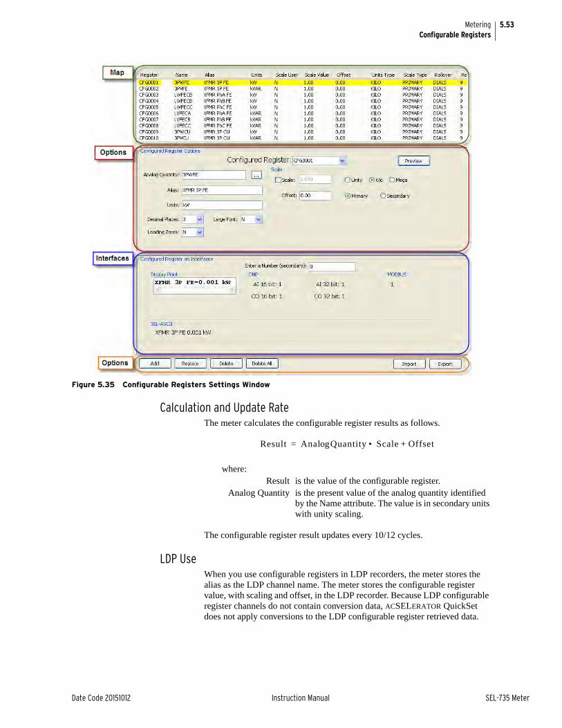
5.53
Date Code 20151012 Instruction Manual SEL-735 Meter
MeteringConfigurable Registers
Figure 5.35 Configurable Registers Settings Window
Calculation and Update RateThe meter calculates the configurable register results as follows.
The configurable register result updates every 10/12 cycles.
LDP UseWhen you use configurable registers in LDP recorders, the meter stores the alias as the LDP channel name. The meter stores the configurable register value, with scaling and offset, in the LDP recorder. Because LDP configurable register channels do not contain conversion data, ACSELERATOR QuickSet does not apply conversions to the LDP configurable register retrieved data.
where:Result is the value of the configurable register.
Analog Quantity is the present value of the analog quantity identified by the Name attribute. The value is in secondary units with unity scaling.
Result Ana Quantitylog Scale Offset+• =

5.54
SEL-735 Meter Instruction Manual Date Code 20151012
MeteringConfigurable Registers
Display PointsConfigurable registers can display on the front-panel LCD in either large or small font.
Display points with large font appear similar to the following text.
E1_OUT (MWH) =
000058493Display points with small font appear similar to the following text.
E1_OUT =000058493 (MWH)
Figure 5.36 shows an example of a configurable register on the front-panel LCD in large font.
Figure 5.36 Front-Panel LCD Display Point Example
Modbus/DNPThe meter additionally scales the configurable register results by the Decimals attribute set in the Configurable Register. For example, if the configurable register result is 5849.3, and the Decimals attribute is 2, the meter scales the result by 100 and passes the value 584930 over the communications channel.
EXAMPLE 5.2 Add Transformer and Line Losses to Configurable Registers
You could add the quantities you want to the configurable register list one by one as this manual described previously, but it may be easier to use the following procedure when adding a large number of quantities to the map. Perform the following steps to add transformer and line losses to the configurable registers map.
Step 1. Create a Microsoft® Excel spreadsheet with CSV format.
Step 2. Add the Attribute names from Table 5.19 to the first row of the spreadsheet.
Step 3. Enter the transformer line and losses analog quantity names and other necessary information in the spreadsheet rows. You do not have to enter the CONFIGREG numbers in chronological order.
See the example of the spreadsheet, shown in Table 5.19, for which 3PWFE and 3PVFE provided configuration in kilowatt and kilovar units.
Table 5.19 Configurable Register Spreadsheet Example
CO
NF
IGR
EG
Nam
e
Alias
Un
its
Dec
imals
Lea
din
gZ
eros
Larg
eFont
Sca
leU
ser
Sca
leV
alu
e
Off
set
Sca
leTy
pe
Un
itsT
ype
Rollov
erTy
pe
Rollov
erD
ials
Rollov
erV
alu
e
1 3PWFE XFMR 3P FE kW 3 N N B 1 0 PRIMARY KILO DIALS 9 1000
2 3PVFE XFMR 3P FE kVAR 3 N N B 1 0 PRIMARY KILO DIALS 9 1000

5.55
Date Code 20151012 Instruction Manual SEL-735 Meter
MeteringVoltage, Current, and Power Calculations
Step 4. Save and close the spreadsheet as a CSV file.
Step 5. Open ACSELERATOR QuickSet, and either open or create a new settings file.
Step 6. Navigate to the Metering > Configurable Registers settings.
Step 7. Click the Import button, as shown in Figure 5.37.
Step 8. Open the spreadsheet you just created.
The imported configurable registers display in the ACSELERATOR QuickSet Configurable Registers setting map, as shown previously in Figure 5.34. You can also export the configurable registers map to a CSV file, as shown in Figure 5.37.
Figure 5.37 Configurable Registers Configuration Tool
Voltage, Current, and Power Calculations
The following information details meter data calculations. The SEL-735 samples analog values at 128 times per cycle and performs a numerical approximation of the integral mathematical equations for voltage, current, and power. These calculations reference the equivalent mathematical equations in IEC 61000-4-30: Edition 2.0 2008-10.
Starting Current The SEL-735 allows you to adjust the starting current threshold of the meter. When the RMS current magnitude is less than the Starting Current Threshold (IST), the meter zeroes current registration. Analog quantities derived from the current quantities will also be impacted. The Starting Current Type setting configures the meter to zero either the RMS derived analog quantities or to zero all current registration. Table 5.20 summarizes the behavior of the Starting Current Type setting.
NOTE: The meter erases old configurable registers when you import a new map.
Delete All Configurable Registers
Import and Export CSVConfigurable Register Maps
Table 5.20 Starting Current Type Setting Behavior
Starting Current Type Setting
Behavior
RMS_ONLY (default value)
When the RMS current magnitude on any phase is less than the Starting Current Threshold value, the meter zeroes the RMS current analog quantities and quantities derived from them of the associated phase. The meter continues to register the fundamental current while the RMS current magnitude is greater than the Starting Current Threshold.
ALL When the RMS current magnitude on any phase is less than the Starting Current Threshold value, the meter zeroes all current registration of the associated phase.

5.56
SEL-735 Meter Instruction Manual Date Code 20151012
MeteringVoltage, Current, and Power Calculations
Neutral Current For Form 9 and Form 36 meters, the SEL-735 calculates the vector sum of the three-phase currents to calculate the neutral current, IN. The following equation shows this calculation.
For Form 5 meters, the SEL-735 assumes that the neutral current is zero. The meter calculates the vector sum of phase currents IA and IC to determine IB, as the following equation shows.
Form 5 Metering Form 5 meters use terminals E07 (VA) and E09 (VC) voltages as the VAB and VCB quantities, respectively. The Form 5 meter calculates VBC as follows.
The meter uses VAB and VCB to calculate VCA, as follows.
The meter also reports all line-to-neutral measurements and calculations as zero.
Form 36 Metering Form 36 meters use terminals E07 (VA) and E09 (VC) voltages as the VAN and VCN quantities, respectively. The Form 36 meter calculates VBN as follows.
This calculated VBN is used in all subsequent calculations for active power, reactive power, etc.
Voltage and Current RMS Magnitudes
The SEL-735 calculates voltage and current magnitudes in accordance with IEC 61000-4-30, Section 4.4, Class A. The time intervals for each measurement are 10 cycles for 50 Hz meters and 12 cycles for 60 Hz meters, commonly known as 10/12 cycle intervals. The sample rate is 128 samples/cycle.
The meter calculates rms voltage and current in accordance with the following equation.
IN IA IB IC+ +=
IB IA IC+( )–=
VBC VCB–=
VCA VCB VAB–=
VBN VAN VCN+( )–=
where:N = Total number of samplesn = Index number
s(n) = Array of periodic v or i samples corresponding to XXx = Form 5: IA, IB, IC, VAB, VBC, or VCA
Form 9 and Form 36: IA, IB, IC, VA, VB, VC, VAB, VBC, or VCA
Xx
N 1–
0 s n( )[ ]2
N-------------------------------------=

5.57
Date Code 20151012 Instruction Manual SEL-735 Meter
MeteringVoltage, Current, and Power Calculations
Half-Cycle RMS Calculation
The meter calculates half-cycle voltage and current rms quantities for sag, swell, and interruption (SSI) detection. Sixteen samples/cycle data provide the source for the calculation, and the half-cycle rms calculation updates every 1/16 cycles.
Half-cycle rms calculations are for SSI detection only and are not available as analog quantities.
Fundamental Only Magnitudes and Angles
The meter calculates fundamental-only quantities and provides these data to analog quantities. Fundamental-only calculations use 16 samples/cycle fundamental measurements. Calculated values update every half-cycle.
The meter references all angles to VA when VA is greater than 13 volts. Otherwise, angles reference IA.
The current and voltage magnitude and angle calculations are as follows.
where x and y are discrete samples taken 90° apart.
Analog QuantitiesThe SEL-735 provides the analog quantities (shown in Figure 5.21) based on the meter form.
P, Q, and S Per-phase fundamental active power (Wx_FUND), reactive power (Qx_FUND), and apparent power (Sx_FUND) calculations use the following equations.
Three-phase fundamental active (W3_FUND) and reactive power (Q3_FUND) calculations use the following equations.
MAG x2
y2
+=
ANG tan1–
2yx---•
=
Table 5.21 Fundamental-Only Power
Meter Form Analog Quantities
Form 9 and Form 36
Vx_MAG and Vx_ANG
where x is A, B, C, AB, BC, or CA
Ix_MAG and Ix_ANG
where x is A, B, C
Form 5 Vx_MAG and Vx_ANG
where x is AB, BC, or CA
Ix_MAG and Ix_ANG
where x is A, B, C
where:x = A, B, or C
Wx_FUND Vx_MAG Ix_MAG Vx_ANG Ix_ANG–( )cos• • =
Qx_FUND Vx_MAG Ix_MAG Vx_ANG Ix_ANG–( )sin• • =
Sx_FUND Vx_MAG Ix_MAG• =

5.58
SEL-735 Meter Instruction Manual Date Code 20151012
MeteringVoltage, Current, and Power Calculations
Form 9 and Form 36 three-phase fundamental apparent power (S3_FUND) calculations use the following equation.
Form 5 three-phase fundamental apparent power (S3_FUND) calculations use the following equation.
These values are available from the fundamental-only power analog quantities.
Fundamental reactive power for each quadrant uses the following nomenclature.
.
10/12 Cycle Power (P, Q, and S)
Active power (P), reactive power (Q), and apparent power (S) calculations use 128 samples/cycle unfiltered voltage and current rms magnitudes as source data.
Active PowerActive power rms calculations use the following equations.
Per-phase quantities:
Three-phase quantity:
where:x = A, B, C, or 3
yyy = REC (received) or DEL (delivered)zz = LD (leading) or LG (lagging)
W3_FUND WA_FUND WB_FUND WB_FUND+ +=
Q3_FUND QA_FUND QB_FUND QB_FUND+ +=
S3_FUND SA_FUND SB_FUND SC_FUND+ +=
S3_FUND W3_FUND2
_Q3FUND2
+=
Qx_yyy_zz
where:x = A, B, C
Vn, In = discrete measurements of N samplesN = the total number of samples
Wx1N----
N 1–
n 0= Vn In• ( )=
W3 WA WB WC+ +=

5.59
Date Code 20151012 Instruction Manual SEL-735 Meter
MeteringVoltage, Current, and Power Calculations
Apparent Power
Apparent power rms calculations use the following equations.
Per-phase quantities:
Three-phase quantity:
Reactive PowerReactive power rms calculations use the following equations. The sign of the fundamental reactive power applies to the calculation results.
Per-phase quantities:
Three-phase quantity:
Power Factor Per-phase and three-phase power factor calculations use fundamental-only quantities and 10/12-cycle quantities. The 10/12-cycle data define the true power factor, while the fundamental-only data define the displacement power factor.
The 10/12-cycle quantities define the true power factor, as in the following equation.
The fundamental-only quantities define the displacement power factor, as in the follow equation.
where:Ix, Vx = the respective phase rms quantities
Ux Ix Vx• =
3U UA UB UC+ +=
where:x = A, B, or C
Qx Ux2
Wx2
–=
3Q QA QB QC+ +=
where:x = A, B, C, or 3
where:x = A, B, C, or 3
PFTxWxUx---------=
PFDxWx_FUNDUx_FUND------------------------------=

5.60
SEL-735 Meter Instruction Manual Date Code 20151012
MeteringVoltage, Current, and Power Calculations
Average and Imbalance Calculations
Average and imbalance quantities update each processing cycle.
Voltage and current imbalance calculations use the following equation.
If V1 is less than 13 V, the meter reports V1_IMB as zero. If I1 is less than 10 mA, the meter reports I1_IMB as zero.
Average value calculations use the following equation.
Voltage and Frequency Deviation Calculations
Voltage and frequency deviation quantities update each processing cycle.
Voltage and frequency deviation calculations use the following equation.
The meter uses the following equation to calculate the percent frequency deviation.
Primary and Secondary Time Sources
The SEL-735 accepts time input from IRIG-B, SNTP, Modbus, DNP3, MV90, and the meter front panel or ACSELERATOR QuickSet.
The meter categorizes time sources as either Primary Time Sources or Secondary Time Sources.
IRIG-B is the only Primary Time Source. SNTP, Modbus, DNP3, MV90, and user-initiated time changes are Secondary Time Sources as shown in Table 5.22.
where:X = I or V (current or voltage)
X1 and X2 = the positive-sequence and negative-sequence components, respectively.
where:X = I or V (current or voltage rms value)
X_IMBX2_MAGX1_MAG-------------------------- 100• =
X_AVGXA XB XC+ +
3---------------------------------------=
where:x = A, B, or C
VNominal = is 120 V
where:FREQ = the frequency of the analog quantity
DEV_VxVx
VNominal----------------------- 100• =
DEV_FFREQ
fNominal--------------------- 100• =

5.61
Date Code 20151012 Instruction Manual SEL-735 Meter
MeteringVoltage, Current, and Power Calculations
When the meter is connected to a Secondary Time Source, the meter accepts each time change as a separate event, and asserts the bit TIMESET for each event. When the meter is connected to a Primary Time Source, the meter synchronizes its clock to that time source.
When synchronized to an IRIG-B time source, the meter asserts the IRIGOK Device Word bit and discards time changes from Secondary Time Sources.
When the IRIG-B time is of sufficient accuracy for Synchrophasor (IEEE C37.118) measurements, the SEL-735 also asserts TSOK.
Local Time and UTC Time
The SEL-735 reports time in local time on every interface except IEC 61850 and IEEE C37.118.2 where time is reported as UTC (Coordinated Universal Time).
When a time source other than SNTP updates the meter time, the time is considered to be local time. SNTP provides time as UTC time; the meter converts UTC to local time by adding UTC_OFF (see Global Settings on page SET.2).
The Effects of Time Changes
Metering and power quality monitoring are dependent on time moving forward at a constant rate. Therefore, time changes, which disrupt this condition are disruptive to metering and power quality functions.
Demand data, for example, is calculated as energy over a specified demand interval, DMTC. If time is changed during a demand interval, the interval will no longer match DMTC. This may lead to erroneous calculations with changing load (ramping up or down). As another example, aggregated values are calculated over time intervals. If the time changes during the measurement interval, the aggregated values may be affected.
On forward time changes, the meter publishes data from each complete or partial time interval. On backward time changes, the meter publishes data at the conclusion of the first complete interval. TheSEL-735 flags any published data that is affected by a time set larger than the TIME_CHG setting.
The magnitude of the error introduced by a time change is directly proportional to the size of the time change. Changing the time by 1 second does not affect data as much as changing the time by 30 seconds. The TIME_CHG setting allows users to set the threshold at which the meter will flag the affected data. The SEL-735 will not flag the data for any time change less than the TIME_CHG threshold, but will flag data for any time change greater than the TIME_CHG threshold. The SEL-735 flags affected data to advise the user that the associated data was affected by a time change event, and therefore may not be as accurate as normal.
Table 5.22 Time Source Classifications for the SEL-735
Primary Time Sources Secondary Time Sources
IRIG-B SNTP
Modbus
DNP3
MV90
user-initiated

5.62
SEL-735 Meter Instruction Manual Date Code 20151012
MeteringVoltage, Current, and Power Calculations
Figure 5.38 shows some sample time changes relative to the TIME_CHG threshold, and shows when data flagging occurs. The SEL-735 publishes and flags data at the Time Interval Boundary after a time change that is greater than the TIME_CHG setting, then clears the flags at the next Time Interval Boundary.
Figure 5.38 Time Changes Relative to the TIME_CHG Setting and Time Interval Boundaries

Date Code 20151012 Instruction Manual SEL-735 Meter
Section 6Reference Manual
Logging
IntroductionThe SEL-735 stores all logged values into nonvolatile memory. If a power loss occurs, the meter retains all previously logged values throughout the power loss duration. Flexible settings control how much memory the meter uses to maximize logging capabilities. The meter provides LDP data to all external interfaces, providing important historical data to the power system.
The meter LDP recorders allow you to log analog quantities and Configurable Registers values, control the log rate, and control the logging function. Using Configurable Registers, you can scale the logged values into primary or secondary units; into mega, kilo, or unity scaling; or apply a user-defined scale factor. The ACSELERATOR QuickSet® SEL-5030 Software interface simplifies scaling and previewing of the values. You can configure the LDP recorders to log the instantaneous value, the quantity’s change-over interval, the average value, the maximum value, or the minimum value. The meter has a separate billing LDP recorder that provides the data to common automatic meter reading tools.
Load Profile ReportThe SEL-735 provides as many as 12 independent load profile recorders. Each load profile recorder has its own settings as shown in Table 6.1. Advanced and Intermediate PQ and Recording options have 12 LDP recorders, while the Basic model has one LDP recorder, which is the billing recorder.
Table 6.1 lists the settings associated with each LDP recorder.
Table 6.1 Load Profile Recorder Settings
Name Range Description
LDFUNCn EOI, COI, AVG, MAX, MIN
Recorder Function, see Table 6.2 for a description of each available recorder function.
LDLISTn Analog Quantity (16 MAX)
Logged quantity list. You can list as many as 16 quantities. Enter 0 or NA to nullify the recorder.
LDARn 3–59 sa; 1, 2, 3, 5, 10, 15, 30, 60, or 120 minutes
a Only available for Advanced and Intermediate PQ and Recording options.
Logging Acquisition Rate Setting. The meter logs values after each acquisition period, defined by LDAR, elapses.
LMDURn 0.05 to 5000 days Logged Values Maximum Duration. The meter starts to overwrite logged values after the period set by LMDUR.

6.2
SEL-735 Meter Instruction Manual Date Code 20151012
LoggingLoad Profile Report
Change LDFUNCn according to the LDP recorder function you want. The meter logs values according to the LDP recorder function, as described in Table 6.2.
Each LDP record contains the time stamp and value of the selected analog quantities resulting in the LDLIST setting.
Billing Recorder We refer to LDP recorder number one as the billing recorder, because it has a functionality slightly different from all other recorders. The meter logs all energy quantities in the billing recorder as the change-over-interval (COI), despite the recorder LDFUNC setting. The meter logs all nonenergy quantities in the billing recorder according to the recorder LDFUNC setting. Additionally, the meter fixes the scaling and units of the quantities (including the source analog quantity of configurable registers) in the billing recorder defined by Table 6.3.
Itron® MV-90® meter reading software reads the billing recorder when it interrogates the meter for energy data. The fixed scaling of the billing recorder ensures MV-90 reads the data correctly.
PQ Recorders All other LDP recorders, known as PQ recorders, scale quantities according to the global scale settings PRI_SCA, VOLT_SCA, POWR_SCA, and ENRG_SCA. The other LDP recorders also log the quantity value according to the LDFUNC setting.
Settings Changes Settings changes you apply to the LDP recorder cause erasure of record values. ACSELERATOR QuickSet® SEL-5030 Software prompts you before sending the settings and erasing LDP data.
ACSELERATOR QuickSet software automatically calculates available LDP storage space depending on the meter configuration. Figure 6.1 shows a screenshot from the LDP settings editor in ACSELERATOR QuickSet, with display of the available recorder memory.
Table 6.2 LDP LDFUNC Recorder Function Description
LDFUNC Setting Function(SETTING, Name)
Function Description
AVG, Average Records the average value during the LDAR period.
EOI, End of Interval Records the value at the end of the interval.
COI, Change-Over-Interval Records the difference in values between the beginning and end of the LDAR period
MAX, Maximum Records the maximum value during the LDAR period
MIN, Minimum Records the minimum value during the LDAR period
Table 6.3 Billing Recorder (LDP Recorder One) Scaling
Quantity Type Scaling
Current (Amps) Primary, Unity
Voltage, Power, Energy Primary, Kilo
HINT: Click the ellipse button shown in Figure 6.1 to open the LDP Builder. This interface provides names and descriptions of each analog quantity and allows for dragging and dropping quantities to create the LDP list.

6.3
Date Code 20151012 Instruction Manual SEL-735 Meter
LoggingLoad Profile Report
Figure 6.1 LDP Settings Interface
LDP Retrieval Use the ACSELERATOR QuickSet HMI to retrieve LDP recorder data. Figure 6.2 shows a screenshot of the LDP HMI window. Refer to Figure 6.2 to retrieve the LDP data.
Figure 6.2 LDP HMI Window
Memory Used
Click to Open LDP Builder
Recorder Selection Time Period Scaling Report Type LDP Data Controls

6.4
SEL-735 Meter Instruction Manual Date Code 20151012
LoggingLoad Profile Report
Use the following guidelines to retrieve LDP data.
➤ Select the LDP recorder.
➢ Figure 6.2 annotates the options for recorder selection. Select the desired LDP recorder. Optionally, check the Get all LDPn recorder data checkbox.
➤ Select the time period of data you want to retrieve.
➢ Figure 6.2 shows the Start and End dates and times in the Time Period section. Set the date and Start and End times you want.
➤ Select the necessary scaling output.
➢ Figure 6.2 shows the Scaling section. Choose your desired scaling options. ACSELERATOR QuickSet exports the LDP data according to the scale factors you have chosen.
➤ Select the Report Type as Standard or MV-90.
➢ ACSELERATOR QuickSet formats the Standard report to SEL standards.
➢ ACSELERATOR QuickSet formats the MV-90 report to replicate an MV-90 Energy report.
➤ Activate an LDP Control:
➢ Click Update LDP to retrieve the LDP recorder data you selected from the meter. The data populate the HMI window.
➢ Click Clear LDP to clear the selected recorder. ACSELERATOR QuickSet prompts you before clearing the LDP recorder.
➢ Click Import LDP to import LDP files and display them in the HMI. The meter can import the following file types.
– CSV (Comma-separated Values file)
– LDP (SEL-formatted LDP file)
– BIN (Binary file)
– TXT (SEL-Formatted Text file)
– HHF (MV-90 Meter-Reading file)
➢ Click Export LDP to export the displayed LDP data to a file. The meter supports exports to the following file types.
– CSV (Comma-separated Values file)
– BIN (Binary file)
– TXT (SEL-Formatted Text file)
– HHF (MV-90 Meter-Reading file)
➢ Click Chart LDP to chart the displayed LDP data.
➢ Click Export All to export all LDP data on the meter. ACSELERATOR QuickSet reads all of the LDP data before the export.

6.5
Date Code 20151012 Instruction Manual SEL-735 Meter
LoggingEvent Reports Overview
Table 6.4 defines the format and fields of LDP records.
Event Reports OverviewThe SEL-735 offers three styles of event reports.
➤ Waveform Capture Event Reports
➤ Sequential Events Recorder (SER) Report
➤ Voltage Sag/Swell/Interruption (VSSI) Report
Waveform Capture Event Reports
Waveform capture, also known as oscillography, allows the SEL-735 to record the voltage and current waveforms associated with programmable trigger conditions, such as a voltage interruption. You can set the sample rate and duration of the waveform capture using the SRATE and LER settings. The supported sample rates are 16, 128, and 512 samples per cycle. The duration of the waveform capture can be set from 15 to 600 cycles. Each waveform capture can contain 1 to 595 cycles of pretrigger data. Adjust the pretrigger data amount with the PRE setting.
The sample rate and duration determines the number of waveform captures that the meter can store in memory. The meter stores the waveform capture in nonvolatile memory. If more waveform captures are triggered than the meter can store, the latest waveform capture overwrites the oldest waveform capture.
The SEL-735 provides an option to generate a filtered 15-cycle event with 16 samples per cycle. The meter filters these reports to provide fundamental-only waveforms-the report does not contain any harmonics or interharmonics. The event reports contain date, time, currents, voltages, frequency, and Device Word bits.
Automated Event Report Retrieval
ACSELERATOR Team® SEL-5045 Software automatically retrieves, databases, and displays SEL-735 event reports. ACSELERATOR Team integrates with the SEL-735, which automatically sends new event reports to the ACSELERATOR Team software allowing near instantaneous display of event waveforms. For additional information on ACSELERATOR Team, please contact your SEL Sales Representative.
Sequential Events Recorder (SER) Report
The meter adds lines in the sequential events recorder (SER) report for a change of state of a programmable condition. The SER lists date and time-stamped lines of information each time a programmed condition changes state.
Table 6.4 LDP Field Format
Offset Name Length (bytes) Binary Equivalent
0 to 1 Record Type 2 16 bit unsigned
2 to 3 Record Size 2 16 bit unsigned
4 to (4 + N – 1) Data Block N (0–65533) 8 bit unsigned
4 + N Record checksum 2 16 bit unsigned

6.6
SEL-735 Meter Instruction Manual Date Code 20151012
LoggingWaveform Capture Event Reports
Voltage Sag/Swell/ Interruption (VSSI) Report
The VSSI report captures voltage disturbances and displays summary or detailed information per IEC 61000-4-30 and CBEMA/ITIC. The SEL-735 reports VSSI disturbances through the SER, SEL ASCII, ACSELERATOR QuickSet, and DNP3 interfaces. The ACSELERATOR QuickSet interface includes graphical representation of disturbances with additional analysis options.
Waveform Capture Event ReportsStandard Waveform Event Report Triggering
The meter triggers (generates) a standard event report when any of the following occur.
➤ Programmable SELOGIC® control equation settings ERn (n = 1–3) asserts to logical 1
➤ Operator manually triggers an event through ACSELERATOR QuickSet HMI
Programmable SELOGIC Control Equation Settings ERnThe programmable SELOGIC control equation event report trigger settings ER1, ER2, and ER3 are set to trigger standard event reports. When setting ERn detects a rising edge, the meter latches the PQALARM word bit and generates an event report (if the SEL-735 is not already generating a report that encompasses the new transition). The factory setting for SEL-735 meters is listed below.
ER1 := SSI_EVE OR FAULT
ER2 := 0
ER3 := 0
Trigger Event ReportFollow the steps below to manually trigger an event.
Step 1. Open ACSELERATOR Quickset HMI Control window and ensure communications with the meter are successful.
Step 2. In the Records section, left-click on the Trigger button, as shown in Figure 6.3.
ACSELERATOR QuickSet prompts you with Trigger an event?
Step 3. Click Yes.
ACSELERATOR QuickSet triggers an event. You may view the event by clicking Tools > Events > View Event Files. See Section 4: ACSELERATOR QuickSet for more information on viewing and retrieving events.
Figure 6.3 shows how to trigger events using the ACSELERATOR QuickSet HMI Control Window.

6.7
Date Code 20151012 Instruction Manual SEL-735 Meter
LoggingWaveform Capture Event Reports
Figure 6.3 Trigger an Event Via ACSELERATOR QuickSet HMI Control Window
Auto Messages The SEL-735 can automatically send unsolicited text messages called Auto Messages over the serial ports to other devices. These messages include device power-on or reset, event triggers, and self-test warnings or failures. To enable Auto Messages on a specific, set AUTO = Y for the serial port desired.
Standard Event Report Summary
Each time the meter generates a standard event report, it also generates a corresponding event summary. Event summaries contain the following information.
➤ Date and time when the event was triggered
➤ System frequency at the front of the event report
➤ Cause of event (e.g., TRI, ER)
➤ Front-panel LED status (targets)
The meter includes the event summary in the standard event report. The identifier, date, and time information is at the top of the standard event report, and the other information follows at the end.
The meter sends event summaries each time an event triggers to any serial ports with setting AUTO = Y.
Retrieving Event Reports
See Section 4: ACSELERATOR QuickSet for instruction to retrieve full-length event reports.
Clearing Event Report Buffer
Follow the steps below to erase all events stored on the meter.
Step 1. Open the ACSELERATOR Quickset HMI Control window and ensure communications with the meter are successful.
Step 2. In the Records section, left-click on the Event Clear button as shown in Figure 6.4.
ACSELERATOR QuickSet prompts you with Clear History Buffer?
Click to trigger an event

6.8
SEL-735 Meter Instruction Manual Date Code 20151012
LoggingSequential Events Recorder (SER) Report
Step 3. Click Yes.
ACSELERATOR QuickSet clears all events stored on the meter.
Figure 6.4 shows how to clear events from the meter using the ACSELERATOR QuickSet HMI Control Window.
Figure 6.4 Clear Events From Meter
Sequential Events Recorder (SER) ReportSER Triggering The meter triggers (generates) an entry in the SER report for a change of state
of any one of the Device Word bits listed in the SER1, SER2, and SER3 trigger settings. The factory-default settings are.
SER1 := HALARM,SALARM,RSTDEM,RSTENGY,RSTPKDM,TEST,DSTCH
SER2 := SSI_EVE,FAULT,HARM02,HARM03,HARM04,HARM05,HARM06,HARM07, HARM08,HARM09,HARM10,HARM11,HARM12,HARM13,HARM14,HARM15
SER3 := NA
The meter monitors each Device Word bit in the SER lists every processing interval. If an element changes state, the meter time-tags the change in the SER.
The meter adds a message to the SER to indicate power up, daylight-saving time or other time changes, or settings change conditions.
Each entry in the SER includes the SER row number, date, time, Device Word bit name, and the bit state.
Making SER Trigger Settings
Enter as many as 24 Device Word bit names in each of the SER settings via ACSELERATOR QuickSet. The meter monitors as many as 72 elements in the SER list (24 in each of the SER equations).
The meter triggers a row in the Sequential Events Recorder (SER) event report for any change of state in any one of the elements listed in the SER1, SER2, or SER3 trigger settings. The meter retains a minimum of 21,000 of the most recent SER entries in nonvolatile memory.
Follow the steps below to create an SER list.
Step 1. Open an ACSELERATOR Quickset settings instance.
Step 2. Navigate to the Events and Logging > Sequential Events Recorder window.
Step 3. Click the SERn ellipse button.
ACSELERATOR QuickSet opens the SER list builder shown in Figure 6.5.
Click to clear SER
Click to confirm

6.9
Date Code 20151012 Instruction Manual SEL-735 Meter
LoggingSequential Events Recorder (SER) Report
Step 4. Select the desired Device Word bits to add to the list.
Step 5. Click the right arrow.
ACSELERATOR QuickSet moves the selected Device Word bits to the Selected section.
Step 6. Repeat Step 4 and Step 5 to add all of the desired elements.
Step 7. Click OK.
Figure 6.5 shows how to open the SER list builder and how to create an SER list.
Figure 6.5 SER List Builder
Retrieve SER Reports Follow the steps below to retrieve SER data stored on the meter.
Step 1. Open the ACSELERATOR Quickset HMI SER window and ensure communications with the meter are successful.
Step 2. Enter the date range you would like to retrieve SER records for or check Get all SER to retrieve all SER data.
Step 3. Click Update SER.
If the requested SER event report rows do not exist, the meter reports No SER Data.
Click to openSER list builder
Click left or right arrowsto select or deselect
Device Word bits
Click OK to create list
Selected Device Word bits
AvailableDevice Word bits

6.10
SEL-735 Meter Instruction Manual Date Code 20151012
LoggingSequential Events Recorder (SER) Report
Figure 6.6 shows the ACSELERATOR QuickSet HMI SER Window where you can retrieve and export SER reports.
Figure 6.6 SER HMI Window
Export the SER Report
You may export the SER data to comma separated (.csv) files or text (.txt) files. Both file formats contain the same information.
Follow the steps below to export SER data.
Step 1. Open the ACSELERATOR Quickset HMI Control window and ensure communications with the meter are successful.
Step 2. Retrieve the desired SER data as explained previously.
ACSELERATOR QuickSet exports the SER data displayed in the SER HMI window.
Step 3. Click Export SER.
ACSELERATOR QuickSet opens up the Save As window.
Step 4. Set the file format to export a .csv or .txt file.
Step 5. Click Save.
ACSELERATOR QuickSet saves the present SER data in a similar format to the HMI display.
Enter date range to filter SER data
Click to retrieve SER data
Click to export SER data
Check box to getall SER data

6.11
Date Code 20151012 Instruction Manual SEL-735 Meter
LoggingVoltage Sag/Swell/Interruption (VSSI) Report
Clear the SER Report Follow the steps below to clear all SER data from the meter.
Step 1. Open the ACSELERATOR QuickSet HMI Control window and ensure communications with the meter are successful.
Step 2. In the Records section, click Clear under SER as shown in Figure 6.7.
Step 3. ACSELERATOR QuickSet prompts you Clear SER Record?
Step 4. Click Yes.
Figure 6.7 Clear SER Report From Meter
Voltage Sag/Swell/Interruption (VSSI) ReportThe VSSI report captures voltage disturbances and displays summary or detailed information per IEC 61000-4-30 and CBEMA/ITIC. The ACSELERATOR QuickSet software interface includes graphical representation of disturbances with additional analysis options as shown in Figure 6.8.
The SEL-735 records VSSI data using an adaptive sampling rate algorithm that maximizes the number of disturbances that the meter can store. Given an average three-second disturbance, the SEL-735 will capture at least 60 independent disturbances and a minimum of 11,000 detailed entries. Sampling rates include fast recording at 4 samples per cycle, medium recording at 1 sample per cycle, slow recording at 1 sample per 64 cycles, and daily at 1 sample per day.
VSSI Settings The VBASE setting defines the initial phase-to-neutral voltage applied to Form 9 and Form 36 connections, and phase-to-phase voltage applied to Form 5 connections. Set AVG_TIME to a time between 1 and 10 minutes to calculate a dynamic VBASE as the average rms phase voltage over the time period defined by AVG_TIME. After VSSI initialization, VBASE for each phase is set to the VBASE setting. When the AVG_TIME period elapses, VBASE for each phase is calculated as the 1-second average rms voltage over the period.
Set AVG_TIME to OFF to disable the dynamic VBASE feature. The VINT, VSAG, and VSWELL trigger thresholds define the percentage of VBASE at which the meter records a disturbance. Hysteresis settings, VINTHYS, VSAGHYS, and VSWELHYS define the percentage above the trigger thresholds at which the VSSI report stops recording.
Click to clear SER
Click to confirm

6.12
SEL-735 Meter Instruction Manual Date Code 20151012
LoggingVoltage Sag/Swell/Interruption (VSSI) Report
VSSI Initialization The following conditions must be met before the VSSI function will capture voltage disturbances.
➤ The phase voltage is greater than 25 V.
➤ The FAULT Device Word bit is deasserted.
➤ Ten seconds have elapsed meeting these conditions.
VSSI Summary Report The VSSI report in the ACSELERATOR QuickSet HMI displays the summary VSSI reports as shown in Figure 6.8. Upon a voltage disturbance, the VSSI reports the event type, date, time, duration, voltages as a percentage of VBASE, and VBASE in compliance with IEC 61000-4-30.
Figure 6.8 shows an example VSSI summary in the ACSELERATOR QuickSet HMI VSSI Window.
Figure 6.8 Example VSSI Response in ACSELERATOR QuickSet
At the end of each disturbance, the VSSI summary reports the following information.
➤ List of events in chronological order.
➤ Event type
➢ SAG
➢ SWELL
➢ INT
➢ TRIG
➤ Date and time the event started.
➤ Event duration in hhh:mm:ss.sss
➤ Minimum and maximum voltage magnitude per IEC 61000-4-30
➤ One of the three CBEMA/ITIC event regions
➢ Prohibited region (PR)
➢ No damage region (ND)
➢ Safe function region (SR)
VSSI Detailed Report The detailed VSSI report includes a point by point record of each VSSI value that is useful for graphing data post-disturbance. Table 6.5 and Table 6.6 describe the meaning of the detailed VSSI status columns.

6.13
Date Code 20151012 Instruction Manual SEL-735 Meter
LoggingVoltage Sag/Swell/Interruption (VSSI) Report
The VSSI recorder archives the following information.
➤ Currents Ia, Ib, Ic, Ig, and In as a percentage of the nominal current rating (shown in the report heading)
➤ Voltages VA, VB, and VC (VAB, VBC, and VCA for Form 5 meters) as a percentage of the VBASE quantity
➤ State of the voltage sag/swell/interruption Device Word bits, by phase
➤ Trigger status
➤ Recorder status
Table 6.5 shows the enumerations of the sag/swell/interruption Device Word bits that the meter gives in the detailed SSI report. Form 9 meters report the SSI Device Word bits SAGA, SAGB, SAGC, etc. Form 5 meters report the SSI Device Word bits SAGAB, SAGBC, SAGCA, etc. Form 36 meters report the SSI Device Word bits SAGA, SAGC, etc., (excludes B-Phase voltage).
See Figure 6.9 for a partial voltage sag/swell/interruption (VSSI) report. The VSSI report example shows a 3-phase voltage interruption lasting about 2.80 seconds with the meter entering daily sampling mode.
Table 6.5 State of the Voltage Sag/Swell/Interruption Device Word Bits
Symbol Meaninga
a Replace p with A-, B-, or C-Phase.
Meter Form 9 and Form 36
Column A represents A-phase
Column B represents B-phase
Column C represents C-phase
Meter Form 5
Column A represents VAB
Column B represents VBC
Column C represents VCA
. No VSSI bits asserted for phase
O Overvoltage (SWp asserted)
U Undervoltage (SAGp asserted)
I Interruption (INTp asserted; SAGp asserted, unless setting VSAG := OFF)
Table 6.6 Status VSSI Column
Symbol Meaning (Action) Duration
R Ready Single entry
P Predisturbance (4 samples per cycle). Always signifies a new disturbance.
12 samples (3 cycles)
F Fast recording mode (4 samples per cycle)
Varies. At least one VSSI element must be asserted.
E End (postdisturbance at 4 samples per cycle)
Up to 16 samples (4 cycles). No VSSI elements asserted.
M Medium recording mode (one sample per cycle)
Maximum of 176 cycles
S Slow recording mode (one sample per 64 cycles)
Maximum of 4096 cycles
D Daily recording mode (one sample per day, just after midnight)
Indefinite
X Data overflow (single entry that indicates that data were lost prior to the present entry)
Single entry

6.14
SEL-735 Meter Instruction Manual Date Code 20151012
LoggingVoltage Sag/Swell/Interruption (VSSI) Report
FEEDER 2 Date: 05/30/00 Time: 14:58:58.620STATION A Time Source: int
FID=SEL-735-X042-V0-Z001001-D20110516 CID=310D
I nom. A B C G = 5 Amp N = 5 Amp Ph-AB Ph-BC Ph-CA
Current(%I nom.) Vbase Volt Vbase Volt Vbase Volt Ph ST# Date Time Ia Ib Ic Ig In (Vsec) %Vbase (Vsec) %Vbase (Vsec) %Vbase ABC
863 04/30/00 22:42:13.500 100.3 100.4 100.1 0.3 0.0 120.00 100.3 120.00 100.1 120.00 100.0 ... R862 05/01/00 00:11:31.944 100.6 100.6 99.6 1.5 1.0 120.00 100.3 120.00 100.1 120.00 100.0 ... P861 05/01/00 00:11:31.949 100.7 100.5 99.5 1.5 1.0 120.00 100.3 120.00 100.1 120.00 100.0 ... P860 05/01/00 00:11:31.953 100.7 100.6 99.6 1.6 1.4 120.00 100.3 120.00 100.1 120.00 100.0 ... P859 05/01/00 00:11:31.957 100.7 100.6 99.6 1.4 1.4 120.00 100.3 120.00 100.1 120.00 100.0 ... P858 05/01/00 00:11:31.961 100.6 100.6 99.6 1.5 1.4 120.00 100.3 120.00 100.1 120.00 100.0 ... P857 05/01/00 00:11:31.965 100.6 100.5 99.6 1.5 1.4 120.00 100.3 120.00 100.1 120.00 100.0 ... P856 05/01/00 00:11:31.969 100.6 100.5 99.6 1.5 1.4 120.00 100.3 120.00 100.1 120.00 100.0 ... P855 05/01/00 00:11:31.974 100.7 100.6 99.6 1.4 1.0 120.00 100.3 120.00 100.1 120.00 100.0 ... P854 05/01/00 00:11:31.978 100.6 100.6 99.6 1.4 1.0 120.00 100.3 120.00 100.1 120.00 100.0 ... P853 05/01/00 00:11:31.982 100.6 100.5 99.6 1.5 1.0 120.00 100.3 120.00 100.1 120.00 100.0 ... P852 05/01/00 00:11:31.986 100.6 100.5 99.6 1.5 1.4 120.00 100.3 120.00 100.1 120.00 100.0 ... P851 05/01/00 00:11:31.990 100.6 100.6 99.6 1.4 1.0 120.00 100.3 120.00 100.1 120.00 100.0 ... P850 05/01/00 00:11:31.993 98.1 93.3 81.4 1.4 1.0 120.00 97.8 120.00 92.9 120.00 81.8 ..U F849 05/01/00 00:11:31.996 71.4 23.6 64.7 1.3 1.0 120.00 71.1 120.00 23.6 120.00 65.0 UUU F848 05/01/00 00:11:31.996 0.0 0.0 0.0 1.3 1.0 120.00 0.0 120.00 0.0 120.00 0.0 III F847 05/01/00 00:11:32.007 0.0 0.0 0.0 1.0 1.0 120.00 0.0 120.00 0.0 120.00 0.0 III F846 05/01/00 00:11:32.011 0.0 0.0 0.0 1.0 1.0 120.00 0.0 120.00 0.0 120.00 0.0 III F845 05/01/00 00:11:32.015 0.0 0.0 0.0 1.0 1.0 120.00 0.0 120.00 0.0 120.00 0.0 III F844 05/01/00 00:11:32.019 0.0 0.0 0.0 1.0 1.0 120.00 0.0 120.00 0.0 120.00 0.0 III F843 05/01/00 00:11:32.024 0.0 0.0 0.0 1.0 1.0 120.00 0.0 120.00 0.0 120.00 0.0 III F842 05/01/00 00:11:32.028 0.0 0.0 0.0 0.9 1.0 120.00 0.0 120.00 0.0 120.00 0.0 III F841 05/01/00 00:11:32.032 0.0 0.0 0.0 1.0 1.0 120.00 0.0 120.00 0.0 120.00 0.0 III F840 05/01/00 00:11:32.036 0.0 0.0 0.0 1.0 1.0 120.00 0.0 120.00 0.0 120.00 0.0 III F839 05/01/00 00:11:32.040 0.0 0.0 0.0 0.9 1.0 120.00 0.0 120.00 0.0 120.00 0.0 III F838 05/01/00 00:11:32.044 0.0 0.0 0.0 0.9 1.0 120.00 0.0 120.00 0.0 120.00 0.0 III F837 05/01/00 00:11:32.049 0.0 0.0 0.0 1.0 1.0 120.00 0.0 120.00 0.0 120.00 0.0 III F836 05/01/00 00:11:32.053 0.0 0.0 0.0 1.0 1.0 120.00 0.0 120.00 0.0 120.00 0.0 III F835 05/01/00 00:11:32.057 0.0 0.0 0.0 0.9 1.0 120.00 0.0 120.00 0.0 120.00 0.0 III F834 05/01/00 00:11:32.061 0.0 0.0 0.0 0.9 1.0 120.00 0.0 120.00 0.0 120.00 0.0 III F833 05/01/00 00:11:32.065 0.0 0.0 0.0 1.0 1.0 120.00 0.0 120.00 0.0 120.00 0.0 III F832 05/01/00 00:11:32.069 0.0 0.0 0.0 1.0 1.0 120.00 0.0 120.00 0.0 120.00 0.0 III D831 05/01/00 00:11:34.753 0.0 0.0 0.0 1.2 1.0 120.00 0.0 120.00 0.0 120.00 0.0 III F830 05/01/00 00:11:34.757 0.0 0.0 0.0 1.1 1.0 120.00 0.0 120.00 0.0 120.00 0.0 III F829 05/01/00 00:11:34.761 0.0 0.0 0.0 1.1 1.0 120.00 0.0 120.00 0.0 120.00 0.0 III F828 05/01/00 00:11:34.765 0.0 0.0 0.0 1.1 1.0 120.00 0.0 120.00 0.0 120.00 0.0 III F827 05/01/00 00:11:34.769 0.0 0.0 0.0 1.1 1.0 120.00 0.0 120.00 0.0 120.00 0.0 III F826 05/01/00 00:11:34.774 0.0 0.0 0.0 1.1 1.0 120.00 0.0 120.00 0.0 120.00 0.0 III F825 05/01/00 00:11:34.778 0.0 0.0 0.0 1.1 1.0 120.00 0.0 120.00 0.0 120.00 0.0 III F824 05/01/00 00:11:34.782 0.0 0.0 0.0 1.1 1.0 120.00 0.0 120.00 0.0 120.00 0.0 III F823 05/01/00 00:11:34.786 0.0 0.0 0.0 1.2 1.0 120.00 0.0 120.00 0.0 120.00 0.0 III F822 05/01/00 00:11:34.790 0.0 0.0 0.0 1.1 1.0 120.00 0.0 120.00 0.0 120.00 0.0 III F821 05/01/00 00:11:34.794 0.0 0.0 0.0 1.1 1.0 120.00 0.0 120.00 0.0 120.00 0.0 III F820 05/01/00 00:11:34.799 0.0 0.0 0.0 1.3 1.0 120.00 0.0 120.00 0.0 120.00 0.0 III F819 05/01/00 00:11:34.802 46.0 80.8 44.4 1.3 1.4 120.00 46.2 120.00 80.1 120.00 44.8 UUU F818 05/01/00 00:11:34.807 99.1 92.7 85.1 1.4 1.4 120.00 99.2 120.00 92.0 120.00 85.4 .UU F817 05/01/00 00:11:34.807 100.2 101.0 99.7 1.4 1.4 120.00 100.3 120.00 100.1 120.00 100.0 ... E816 05/01/00 00:11:34.815 100.3 101.0 99.6 1.7 1.4 120.00 100.3 120.00 100.1 120.00 100.0 ... E
Figure 6.9 Example Voltage Sag/Swell/Interruption (VSSI) Report (Meter Form 9)
VSSI Report Memory Details
The meter retains a minimum of 11,000 of the most recent VSSI entries in nonvolatile memory. If the VSSI recorder memory clears while an VSSI report is being displayed, the VSSI report will stop and display this message.
Command Aborted, Data overwrite occurred
VSSI Device Word Bits Upon a voltage disturbance, the meter asserts Device Word Bits that offer a binary disturbance summary, and latches the PQALARM word bit. Mapping these VSSI Device Word Bits to the Sequential Events Recorder (SER) allows rapid analysis of a disturbance and its corresponding CBEMA/ITIC region.

Date Code 20151012 Instruction Manual SEL-735 Meter
Section 7Inputs/Outputs and
SELOGIC Control Equations
OverviewThis section explains the settings and operation of the logic inputs/outputs and SELOGIC® control equations for the SEL-735.
Inputs/Outputs on page 7.2
➤ KYZ Outputs
➤ Output Contacts
➤ DC Analog Outputs
➤ Optoisolated Inputs
➤ Remote Control Bits
SELOGIC Control Equations on page 7.10
➤ Latch Control Bits
➤ SELOGIC® Control Equation Variables/Timers
➤ Math Variables
➤ Virtual Bits
➤ MIRRORED BITS® Communications
➤ Reset Trigger Equations
➤ Graphic Logic Editor

7.2
SEL-735 Meter Instruction Manual Date Code 20151012
Inputs/Outputs and SELOGIC Control EquationsInputs/Outputs
Inputs/OutputsTable 7.1 describes the inputs or settings and outputs of the meter function.
KYZ Pulse Outputs KYZ pulse outputs are digital pulses that represent a specific amount of energy. The SEL-735 measures energy data and converts it to KYZ output pulses. You can then map the KYZ output pulses to output contacts to communicate the energy data to remote devices.
The SEL-735 KYZ pulses can produce any energy analog quantity. The meter provides as many as four energy quantities for Form A contacts. Solid-state output contacts are vital for KYZ operation to prevent contact wear and premature failure.
Table 7.2 describes the settings associated with the KYZ pulses. Replace n with the KYZ pulse number of 1 to 4.
The SEL-735 also provides a test pulse, KYZDT, while the meter is in TEST mode. The normal KYZ pulses, KYZD1–KYZD4, deassert and stop pulsing while the meter is in TEST mode. See Section 9: Testing and Troubleshooting for more details of the meter while it is in TEST mode.
Table 7.1 SEL-735 Logic Inputs and Output Model Reference
Description Input/Setting Model Reference
KYZ Outputs KEn_SCALE, KEn, KET, KEn_UNIT, KYZDn, KYZPWn, KEn_OUT
KYZDn, KYZDT
Output Contacts OUTn Word bits OUTn
Analog Outputs AOnAQ, AOnAQL, AOnAQH, AOnL, AOnH
Current Output
Optoisolated Inputs INnD INn Word bits
Remote Control Bits Communications Channels: SEL, DNP, and Modbus®
RB01–RB16 Word bits
Local Control Bits Front-Panel Pushbuttons PB01–PB04 and RESET Word bits
Table 7.2 KYZ Output Settings and Ranges
Setting Definition Default Range
KEn_SCALE KEn Scale. Sets the scale of KEn. SEC PRI, SEC
KEn Watthour constant. Sets the KYZ pulse energy constant.
1.8000 0.0001–9999
KEn_UNIT KEn Units. Sets the units of KEn. UNITY UNITY, KILO, MEGA
KYZDna
a n represents the element number. Replace n with the KYZ pulse number 1 to 4.
Demand Type to Output n. Sets the energy analog quantity for output.
WH3_DEL Energy Quantities
KYZPWn KYZ Minimum Pulse Width n. Sets the minimum pulse width.
25 ms 25, 50, 75, 100 ms
KEn_OUT KYZ Output. Maps the KYZ pulses to an output contact.
OFF OFF, OUT401–OUT404

7.3
Date Code 20151012 Instruction Manual SEL-735 Meter
Inputs/Outputs and SELOGIC Control EquationsInputs/Outputs
The settings KEn, KEn_SCALE, KEn_UNITS determine the number of KYZ triggers or KYZ state transitions. The meter calculates the number of KYZ triggers using Equation 7.1.
Equation 7.1
Any remainder left over from the previous calculation carries over to the next calculation. Any remainder resets to zero if a meter loses power for any reason. This means that any non-zero remainder prior to loss of meter power disappears during the power loss.
You can use two methods to collect KYZ energy data. The first uses a pickup that records the rising edge of a pulse; the second records the rising and falling edges. You may configure the KYZ outputs of the SEL-735 using ACSELERATOR QuickSet® SEL-5030 Software without having to enter any logic expressions.
Figure 7.1 KYZ Pulse Pickup
In Figure 7.1, each trigger occurs when the SEL-735 meters the KEn amount of energy. The first diagram in Figure 7.1 shows energy triggers asserting after each KYZ Minimum Pulse Width time period elapses. The second diagram in
where:Ke = KEn • KEn_UNITS / trigger
t = time in hoursRprevious = Energy remaining from the previous calculation of the
number of KYZ triggers
Number of KYZ triggersTotal Energy in time t( ) Rprevious+
Ke--------------------------------------------------------------------------------------=
where:KEn_UNITS = 1 if KEn_UNITS = UNITY
= 1000 if KEn_UNITS = KILO= 1000000 if KEn_UNITS = MEGA
KYZDn DeviceWord Bit State
t1 = KYZPWn KYZ Minimum Pulse Width (ms)
Trigger
Deasserted
Deasserted
Asserted
KYZDn DeviceWord Bit State
Trigger
Asserted
t1t1t1 t1

7.4
SEL-735 Meter Instruction Manual Date Code 20151012
Inputs/Outputs and SELOGIC Control EquationsInputs/Outputs
Figure 7.1 shows energy triggers asserting prior to the KYZ Pulse Width time period. If a trigger occurs before the Minimum Pulse Width period elapses (as shown in the second diagram in Figure 7.1), then the meter adds these pulses to the remainder of Equation 7.1. The meter applies the remainder to the KYZ Device Word Bit after each Minimum Pulse Width period expires.
To produce outputs of three-phase watt-hours delivered (WH3_DEL) from KYZ1 to OUT401, set the KYZ set follows.
EKYZ := 1
KE1_SCALE := PRI
KE1 := 1.8
KE1_UNIT := KILO
KYZD1 := WH3_DEL
KYZPW1 := 25
KE1_OUT := OUT401
For every 1.8 kWh primary the SEL-735 measures, Device Word bit KYZD1 changes state and maintains the new state for at least the time KYZPW1 defines (25 ms in this case). The state of OUT401 follows the Device Word bit KYZD1 state. KYZD1 changes state again after another accumulation of 1.8 kWh.
You can use Equation 7.2 to calculate total energy at the receiving end of these triggers.
If KEn_SCALE is set to SEC:
If KEn_SCALE is set to PRI:
Equation 7.2
Where:KEn_UNITS = UNITS
UNIT = 1KILO = 1000
MEGA = 1000000
Total Energy (Pri) Number of triggers CTR PTR KEn UNITS• • • • =
Total Energy (Sec) Number of triggers KEn UNITS• • =
Total Energy (Pri) Number of triggers KEn UNITS• • =
Total Energy (Sec) Number of triggers KEn UNITS CTR PTR• ( )• • • =

7.5
Date Code 20151012 Instruction Manual SEL-735 Meter
Inputs/Outputs and SELOGIC Control EquationsInputs/Outputs
Output Contacts Three output contacts (two Form A contacts and one Form C contact) come standard with the SEL-735. Each output contact follows the state of the associated Device Word bit. You can add four additional output contacts. The output contacts update every half power system cycle.
Pulse Output ContactsYou can pulse the output contacts from the ACSELERATOR QuickSet HMI as the following steps explain.
Step 1. From an ACSELERATOR QuickSet HMI, navigate to the control window.
Step 2. In the Pulse Outputs section, shown in Figure 7.2, select the output contact you want to pulse. This example uses OUT101.
Step 3. Set the amount of time to pulse the output contact from 1 to 30 seconds. This example uses one second.
Step 4. From the Pulse Outputs window, click the Pulse button. A window opens to prompt you to pulse the output contact.
Step 5. Click Yes to assert the command.
Figure 7.2 Pulse Output Contact Example
Contact Output as an Alarm OutputBy default, the SEL-735 maps the Device Word bits SALARM (software alarm) and HALARM (hardware alarm) to output contact OUT103, as follows.
OUT103 = NOT (SALARM OR HALARM)
The Device Word bits SALARM and HALARM are normally deasserted. When the meter enters Access Level 2, the SALARM Device Word bit momentarily asserts. The HALARM Device Word bit asserts momentarily for hardware warnings and asserts permanently for hardware failures.
Table 7.3 Output Contact Settings and Default Settings
Setting Definition Device Word Bit Default Setting Range
OUT101 Output Contact 101 SELOGIC control equation that controls OUT101.
OUT101 0 SELOGIC control equation
OUT102 Output Contact 102 SELOGIC control equation that controls OUT102.
OUT102 0 SELOGIC control equation
OUT103 Output Contact 103 SELOGIC control equation that controls OUT103.
OUT103 NOT (SALARM OR HALARM)
SELOGIC control equation
OUT401–OUT404
Output Contact 401–404 SELOGIC control equations that control OUT401–OUT404.
OUT401–OUT404 0 SELOGIC control equation

7.6
SEL-735 Meter Instruction Manual Date Code 20151012
Inputs/Outputs and SELOGIC Control EquationsInputs/Outputs
Output contact OUT103 is normally closed when SALARM and HALARM are deasserted. If SALARM or HALARM assert then OUT103 opens, indicating a software or hardware warning or alarm. You can change the default settings of output contact OUT103.
DC Analog Output The optional analog output/digital output card for the SEL-735 provides as many as four dc analog outputs.
Each analog output acts as a programmable transducer. The SEL-735 measures a user-selectable analog quantity and produces a dc current of ±1.2 mA or ±24.0 mA that is proportional to the value it measures. The meter updates analog outputs every 100 milliseconds or faster.
You can output all basic analog quantities to dc analog outputs.
Table 7.4 describes each analog output setting. When AOxxAQ is set to OFF the meter hides the associated settings.
ExampleSuppose that our load has a three-phase maximum delivered power of 1 MW (positive) and maximum received power of 1 MW (negative). We want an analog current output that is proportional to the three-phase power, with a conversion factor of 1 mA/MW.
Step 1. Set Analog Quantity AO01AQ to W3.
Step 2. Set Analog Quantity Low AO01AQL to —1000.000.
Step 3. Set Analog Quantity High AO01AQH to 1000.000.
Step 4. Set Low Analog Output Value AO01L to —1.000.
Step 5. Set High Analog Output Value AO01H to 1.000.
Table 7.4 Analog Output Settings and Default Settings
Settinga
a Replace xx with Analog Output numbers 01–04.
Definition Default Range
AOxxAQ Analog Quantity. Sets the analog quantity for the output. OFF OFF, valid analog quantities
AOxxAQL Analog Quantity Low. Sets the measured value that creates the mini-mum current output for the selected analog quantity in primary units. Enter voltage, power, and energy quantities in primary kilo units; enter current and all other quantities in unity primary units.
–1.000 –2147483647.000
to
2147483647
AOxxAQH Analog Quantity High. Input limit. Sets the measured value that creates the maximum current output for the selected analog quantity in primary units. Enter voltage, power, and energy quantities in primary kilo units; enter current and all other quantities in unity primary units.
1.000 –2147483647.000
to
2147483647
AOxxL Low Analog Output Value (mA). Sets the minimum output current value when the analog quantity equals the analog quantity low value.
–1.000 or 4.000
–1.200 to 1.200 mA
or
–24.000 to +24.000 mA
AOxxH High Analog Output Value (mA). Sets the maximum output current value when the analog quantity equals the analog quantity high value.
1.000 or 20.000
–1.200 to 1.200 mA
or
–24.000 to +24.000 mA
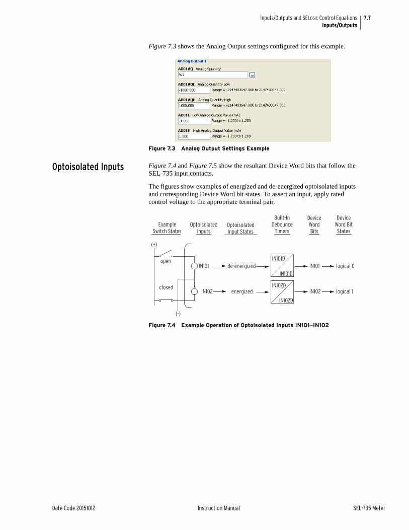
7.7
Date Code 20151012 Instruction Manual SEL-735 Meter
Inputs/Outputs and SELOGIC Control EquationsInputs/Outputs
Figure 7.3 shows the Analog Output settings configured for this example.
Figure 7.3 Analog Output Settings Example
Optoisolated Inputs Figure 7.4 and Figure 7.5 show the resultant Device Word bits that follow the SEL-735 input contacts.
The figures show examples of energized and de-energized optoisolated inputs and corresponding Device Word bit states. To assert an input, apply rated control voltage to the appropriate terminal pair.
Figure 7.4 Example Operation of Optoisolated Inputs IN101–IN102
open
closed
ExampleSwitch States
OptoisolatedInput States
OptoisolatedInputs
Built-InDebounce
Timers
DeviceWordBits
DeviceWord BitStates
IN101 de-energized IN101 logical 0
energizedIN102 IN102 logical 1
(+)
(-)
IN101D
IN101D
IN102D
IN102D

7.8
SEL-735 Meter Instruction Manual Date Code 20151012
Inputs/Outputs and SELOGIC Control EquationsInputs/Outputs
Figure 7.5 Example Operation of Optoisolated Inputs IN401–IN404, Extra I/O Board
Input Debounce Timers
Each input has settable pickup/dropout timers (IN101D and IN102D) for input energization/de-energization debounce or may be set to AC. The meter samples each input at least 16 times per power system cycle and updates the Device Word bit every 4 ms.
You can set the input delay times, IN101D–IN102D and IN401D–IN404D from 0 to 8 ms, in 1 ms increments. Use this range for a dc signal input. When you enter this setting, each input voltage sample must exceed the minimum necessary voltage threshold throughout the entire debounce time delay. The associated Device Word bit asserts after the input voltage signal exceeds the minimum threshold throughout the entire debounce time delay.
The AC setting allows the input to sense alternating control signals. The input has a maximum pickup time of 25 ms and a maximum dropout time of 25 ms. With the Debounce Time set to AC, the device measures two successive 1 ms samples, compares the measurement to the input voltage threshold, then asserts the corresponding Device Word bit. The input deasserts in the same fashion, but measures 12 successive samples instead of two.
ExampleSwitch States
OptoisolatedInput States
OptoisolatedInputs
Built-InDebounce
Timers
DeviceWordBits
DeviceWord BitStates
open
closed
IN401 de-energized IN401 logical 0
energizedIN402 IN402 logical 1
(+)
IN401D
IN401D
IN402D
IN402D
open
closed
IN403 de-energized IN403 logical 0
energizedIN404 IN404 logical 1
(-)
IN403D
IN403D
IN404D
IN404D
Table 7.5 Input Debounce Default Settings and Valid Ranges
Setting Definition Default Range
IN101D–IN102D (standard)
Input n Debounce Time. Sets the debounce time of the input.
Where n is 101, 102, 401, 402, 403, or 404.
5 ms 0–8, AC
IN401D–IN404D (optional)
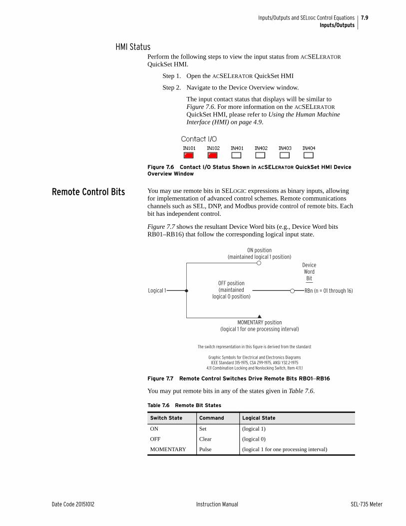
7.9
Date Code 20151012 Instruction Manual SEL-735 Meter
Inputs/Outputs and SELOGIC Control EquationsInputs/Outputs
HMI StatusPerform the following steps to view the input status from ACSELERATOR QuickSet HMI.
Step 1. Open the ACSELERATOR QuickSet HMI
Step 2. Navigate to the Device Overview window.
The input contact status that displays will be similar to Figure 7.6. For more information on the ACSELERATOR QuickSet HMI, please refer to Using the Human Machine Interface (HMI) on page 4.9.
Figure 7.6 Contact I/O Status Shown in ACSELERATOR QuickSet HMI Device Overview Window
Remote Control Bits You may use remote bits in SELOGIC expressions as binary inputs, allowing for implementation of advanced control schemes. Remote communications channels such as SEL, DNP, and Modbus provide control of remote bits. Each bit has independent control.
Figure 7.7 shows the resultant Device Word bits (e.g., Device Word bits RB01–RB16) that follow the corresponding logical input state.
Figure 7.7 Remote Control Switches Drive Remote Bits RB01–RB16
You may put remote bits in any of the states given in Table 7.6.
Table 7.6 Remote Bit States
Switch State Command Logical State
ON Set (logical 1)
OFF Clear (logical 0)
MOMENTARY Pulse (logical 1 for one processing interval)
Logical 1OFF position(maintained
logical 0 position)
ON position(maintained logical 1 position)
MOMENTARY position(logical 1 for one processing interval)
RBn (n = 01 through 16)
DeviceWordBit
The switch representation in this figure is derived from the standard:
Graphic Symbols for Electrical and Electronics DiagramsIEEE Standard 315-1975, CSA Z99-1975, ANSI Y32.2-1975
4.11 Combination Locking and Nonlocking Switch, Item 4.11.1

7.10
SEL-735 Meter Instruction Manual Date Code 20151012
Inputs/Outputs and SELOGIC Control EquationsSELOGIC Control Equations
HMI ControlControl remote bits through the ACSELERATOR QuickSet HMI, as the following text explains.
Step 1. From the ACSELERATOR QuickSet HMI, navigate to the control window.
Step 2. In the Remote Bits section, shown in Figure 7.8, left-click one of the virtual LEDs. The Remote Bits window opens, as shown in Figure 7.8.
Step 3. From the Remote Bits window, select the Set, Clear, or Pulse command.
➢ Set command asserts the remote bit indefinitely.
➢ Clear command deasserts the remote bit indefinitely.
➢ Pulse command asserts the remote bit for one processing cycle and then deasserts the remote bit.
Step 4. Press OK or Apply to assert the command.
Figure 7.8 Control Remote Bits Through ACSELERATOR QuickSet HMI
You can also control remote control bits through other communications channels. Please see the DNP or Modbus section for details on remote bit control via those protocols.
States When Power Is Lost to Device or Settings Are ChangedWhen the device loses power, remote bit states always return to OFF.
If a remote bit is ON before a setting change, it returns to ON after the change. If a remote bit is OFF before a settings change, it returns to the OFF position after the change.
SELOGIC Control EquationsTable 7.7 describes all SEL-735 SELOGIC control equations and shows the inputs or settings and outputs corresponding to each control equation. The inputs or settings and outputs of each category are shown.
NOTE: If the remote bit is initially asserted before the Pulse command, the remote bit deasserts after completion of the command.
Table 7.7 SELOGIC Control Equation Inputs/Settings and Outputs (Sheet 1 of 2)
Description Input/Setting Output
Latch Bits SETn, RSTn LTn
Control Equation Vari-ables/Timers
SVn, SVnPU, SVnDO SVn, SVnT
Math Variables MVn MVn
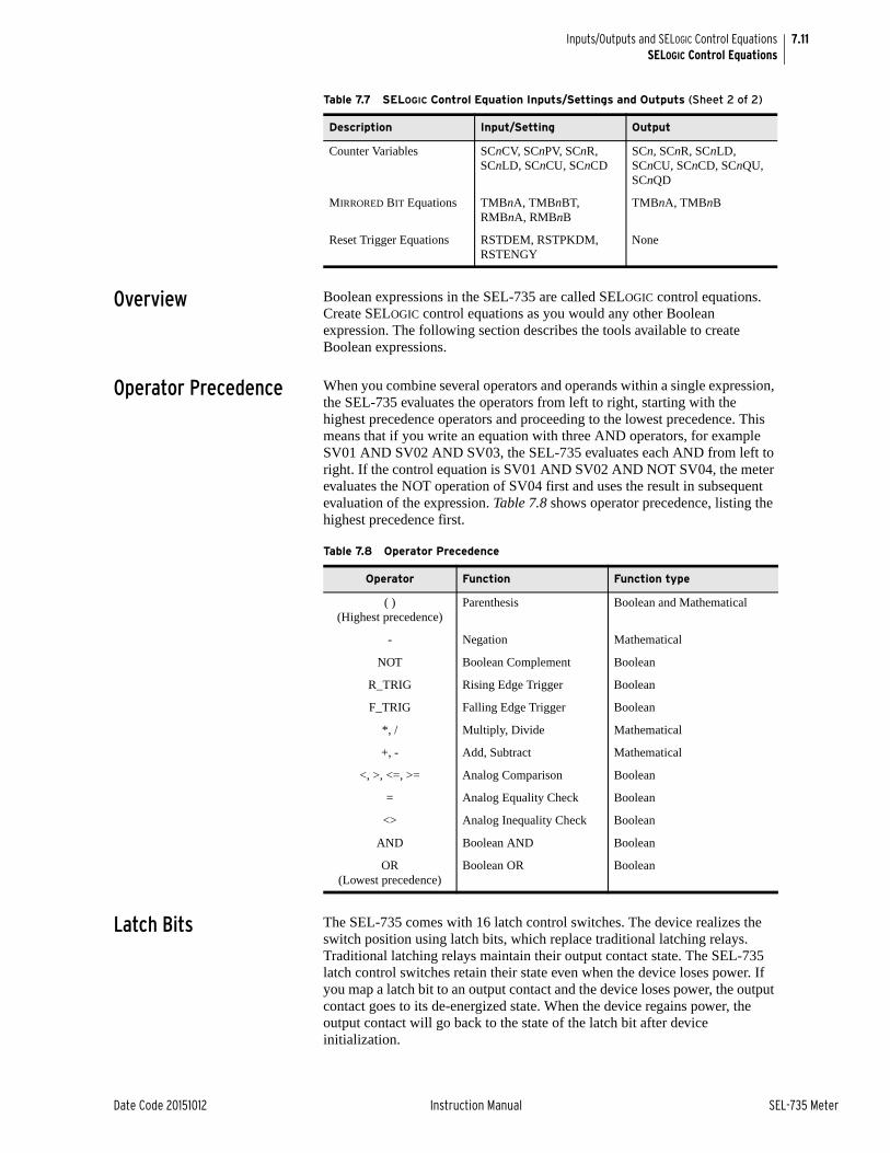
7.11
Date Code 20151012 Instruction Manual SEL-735 Meter
Inputs/Outputs and SELOGIC Control EquationsSELOGIC Control Equations
Overview Boolean expressions in the SEL-735 are called SELOGIC control equations. Create SELOGIC control equations as you would any other Boolean expression. The following section describes the tools available to create Boolean expressions.
Operator Precedence When you combine several operators and operands within a single expression, the SEL-735 evaluates the operators from left to right, starting with the highest precedence operators and proceeding to the lowest precedence. This means that if you write an equation with three AND operators, for example SV01 AND SV02 AND SV03, the SEL-735 evaluates each AND from left to right. If the control equation is SV01 AND SV02 AND NOT SV04, the meter evaluates the NOT operation of SV04 first and uses the result in subsequent evaluation of the expression. Table 7.8 shows operator precedence, listing the highest precedence first.
Latch Bits The SEL-735 comes with 16 latch control switches. The device realizes the switch position using latch bits, which replace traditional latching relays. Traditional latching relays maintain their output contact state. The SEL-735 latch control switches retain their state even when the device loses power. If you map a latch bit to an output contact and the device loses power, the output contact goes to its de-energized state. When the device regains power, the output contact will go back to the state of the latch bit after device initialization.
Counter Variables SCnCV, SCnPV, SCnR, SCnLD, SCnCU, SCnCD
SCn, SCnR, SCnLD, SCnCU, SCnCD, SCnQU, SCnQD
MIRRORED BIT Equations TMBnA, TMBnBT, RMBnA, RMBnB
TMBnA, TMBnB
Reset Trigger Equations RSTDEM, RSTPKDM, RSTENGY
None
Table 7.7 SELOGIC Control Equation Inputs/Settings and Outputs (Sheet 2 of 2)
Description Input/Setting Output
Table 7.8 Operator Precedence
Operator Function Function type
( )(Highest precedence)
Parenthesis Boolean and Mathematical
- Negation Mathematical
NOT Boolean Complement Boolean
R_TRIG Rising Edge Trigger Boolean
F_TRIG Falling Edge Trigger Boolean
*, / Multiply, Divide Mathematical
+, - Add, Subtract Mathematical
<, >, <=, >= Analog Comparison Boolean
= Analog Equality Check Boolean
<> Analog Inequality Check Boolean
AND Boolean AND Boolean
OR (Lowest precedence)
Boolean OR Boolean

7.12
SEL-735 Meter Instruction Manual Date Code 20151012
Inputs/Outputs and SELOGIC Control EquationsSELOGIC Control Equations
Figure 7.9 Traditional Latching Relay
Pulse the SET input to close (assert) the latching relay output contact. Pulse the RESET input to open (deassert) the latching relay output contact. Often, the external contacts wired to the latching relay inputs are from remote control equipment (e.g., SCADA, RTU, remote bits).
Table 7.9 shows the default settings and range for the latch bits.
Figure 7.10 Latch Control Switches Drive Latch Bits LT01–LT16
Figure 7.10 shows the logical diagram of the latch bit. Device Word bits LT01–LT16 are the outputs of the logic scheme. Use these latch bits in SELOGIC control equations.
Table 7.10 shows the logic states of the latch bits. If RESET equals a logical one, the latch bit deasserts. If SET equals a logical one, the latch bit asserts. RESET always takes priority over SET.
Table 7.9 Latch Bit Settings and Default Settings
Setting Definition Default Range
SETn SELOGIC control equation that, when evaluates as TRUE, sets the Latch Bit. Enter NA to disable.
NA SELOGIC control equation
RSTn SELOGIC control equation that, when evaluates as TRUE, resets the Latch Bit. Enter NA to disable.
NA SELOGIC control equation
Table 7.10 Latch Bit Logic Table
Latch State SETn RSTn LTn
SET OR RESET 0 0 No change
SET 1 0 1
RESET 0 1 0
RESET 1 1 0
SetInput
ResetInput
OutputContact
TraditionalLatching
Relay
(+)
(–)
SETn
RSTn
LTn(Set)
(Reset)(n = 01 through 16)
DeviceWordBits
SELOGICSettings

7.13
Date Code 20151012 Instruction Manual SEL-735 Meter
Inputs/Outputs and SELOGIC Control EquationsSELOGIC Control Equations
Latch Bits: Application IdeasYou can use latch control switches for such applications as the following.
➤ Battery charger health status alarm latching
➤ Predictive demand alarm enable/disable
You can apply latch control switches to almost any control scheme. The following is an example of using a latch control switch to add the battery charger health status to the meter ALARM contact (output contact OUT103 by default).
Example: Adding Battery Charger Health Status to ALARM ContactUse a latch control switch to add battery charger health status alarm latching to the SEL-735. In this example, an external SCADA contact connects to optoisolated input IN102, as shown in Figure 7.11. The Device Word bit IN102 state either sets or resets the latch bit LT01. Use a remote bit instead of an optoisolated input, if your application warrants it.
If you pulse the battery charger health status contact while the ALARM output contact is closed, the ALARM output contact disables. If you pulse the battery charger health status contact again, the ALARM output contact enables again. Each pulse of the battery charger health status contact changes the state of the ALARM output contact. The control operates in a cyclic manner.
Figure 7.11 Battery Charger Health Status Contact Pulses Input IN102 to Enable/Disable ALARM Output Contact
You may implement this ALARM output contact logic using the SELOGIC control equation settings as displayed in Figure 7.12. Note that the figure includes an extra timer not included in the settings. The next example shows the use of this timer. Figure 7.13 shows the timing for this example.
SET01 := (R_TRIG IN102) AND (NOT LT01)
RST01 := (R_TRIG IN102) AND LT01
OUT103 := NOT (SALARM OR HALARM) OR (NOT LT01)
Figure 7.12 Single Input to Control ALARM
(+)
Battery ChargerHealth Status
Contact
(—)
SEL Input IN102Enable/Disable ALARMOutput Contact
Latch Bit
OUT103
RST01
SET01 LT01
SALARM
IN102
R_TRIG
SV06PU
SV06DO
SV06 SV06T
HALARM(Reset)
SELOGICSettings SELOGIC
Settings
SELOGICSettings
DeviceWordBits
DeviceWordBits
DeviceWordBitsDevice
WordBits
(Set)NOT LT01

7.14
SEL-735 Meter Instruction Manual Date Code 20151012
Inputs/Outputs and SELOGIC Control EquationsSELOGIC Control Equations
Figure 7.13 Latch Control Switch Operation Time Line
A variation of the previous example adds more security by adding a timer with equal pickup/dropout times, as shown in Figure 7.12. Suppose that you set both SV06PU and SV06DO to 5 seconds. The SV06T timer prevents the state of latch bit LT01 from switching/changing at a rate faster than once every 5 seconds. Figure 7.14 shows the timing for this example.
SV06 := LT01
SET01 := (R_TRIG IN102) AND (NOT SV06T)
RST01 := (R_TRIG IN102) AND SV06T
OUT103 := NOT (SALARM OR HALARM) OR (NOT LT01)
Note in Figure 7.12 that Latch Bit LT01 uses feedback from the SELOGIC settings SET01 and RST01. The feedback to LT01 determines whether input IN102 operates the SET01 or RST01 input. If LT01 = logical 0, input IN102 operates SET01. If Latch Bit LT01 = logical 1, input IN102 operates RST01.
Figure 7.14 Latch Control Switch (With Time-Delay Feedback) Operation Time Line
RST01
R_TRIG IN102
IN102
SET01
LT01
RisingEdge
OneProcessingInterval
Pulse 1 Pulse 2 Pulse 3 Pulse 4
RisingEdge
RisingEdge
RisingEdge
RST01
R_TRIG IN102
IN102
SET01
RisingEdge
OneProcessingInterval
SV06DOSV06PU
Pulse 1 Pulse 2 Pulse 3 Pulse 4
RisingEdge
RisingEdge
No Effect
No Effect
RisingEdge
SV06 := LT01
SV06T

7.15
Date Code 20151012 Instruction Manual SEL-735 Meter
Inputs/Outputs and SELOGIC Control EquationsSELOGIC Control Equations
Latch Bits: Nonvolatile StatePower Loss
The device retains the states of latch bits if it loses, then regains power. This feature makes the latch bit feature behave the same as traditional latching relays. In a traditional installation, if the panel loses power, the latching relay output contact position remains unchanged.
Settings ChangeIf you change individual settings, the device retains the state of latch bits, much like in the preceding Power Loss explanation.
If the individual settings change causes a change in SELOGIC control equation settings SETn or RSTn (n = 01–16), it is possible for the retained states of the latch bits to change, subject to the newly enabled settings SETn or RSTn.
Make Latch Control Switch Settings With CareThe SEL-735 stores latch bit states in nonvolatile memory, so the device can retain these states during power losses or setting changes. The device can write to nonvolatile memory for a finite number of times for all cumulative Latch Bit state changes. Exceeding the limit can result in a NONVOL self-test failure. An average of 70 cumulative latch bit state changes per day can occur for a 25-year meter service life.
Due to the finite number of writes to nonvolatile memory, you should make changes to latch bit settings with care. Settings SETn and RSTn cannot result in continuous cyclical operation of Latch Bit LTn. Use timers to qualify conditions set in settings SETn and RSTn. If you use any optoisolated inputs in settings SETn and RSTn, the inputs have their own debounce timer that can help in providing the necessary time qualification.
In the preceding example application of adding a battery charger health status to the ALARM contact, you should not configure the device to assert/deassert the battery charger health status contact continuously. This situation would cause Latch Bit LT01 to change state continuously. Note that the rising edge operators in the SET01 and RST01 settings keep Latch Bit LT01 from cyclical operation for any single assertion of the battery charger health status contact.
SELOGIC Control Variables/Timers
The SEL-735 has 16 SELOGIC control variables and timers. Each SELOGIC control variable contains an associated pickup and dropout timer. The pickup and dropout timers have a range from zero to several days, with millisecond resolution.
Table 7.11 shows the associated SELOGIC control equation, pickup timer, and dropout timer settings and ranges.
NOTE: If a latch bit is set to a programmable output contact, such as OUT103 := LT02, and the meter loses power, the meter stores the state of the latch bit in nonvolatile memory, but the output contact goes to its de-energized state. When power returns to the meter, the programmable output contact returns to the state of the latch bit after meter initialization.
Table 7.11 SELOGIC Control Equation Settings and Default Settings
Setting Definition Default Range
SVn SELOGIC control equation that, when eval-uated as TRUE, asserts the variable input.
NA SELOGIC control equation
SVnPU Time required for the variable input to remain asserted before the variable output (SVnT) asserts.
0.000 seconds 0.000 to 1000000.000
SVnDO Time required for the variable input to remain deasserted before the variable out-put (SVnT) deasserts.
0.000 seconds 0.000 to 1000000.000

7.16
SEL-735 Meter Instruction Manual Date Code 20151012
Inputs/Outputs and SELOGIC Control EquationsSELOGIC Control Equations
Figure 7.15 SELOGIC Control Equation Variables and Timers
Timers Reset When Power Is Lost or Settings Are ChangedIf the device loses power or if settings change, the SELOGIC control equation variables/timers reset. Device Word bits SVn and SVnT (n = 01–16) reset to logical 0 after power restoration or a settings change.
Figure 7.16 shows an effective seal-in logic circuit, created by use of Device Word bit SV07 (SELOGIC control equation variable SV07) in SELOGIC control equation SV07.
SV07 := (SV07 OR OUT101) AND (OUT102 OR OUT401)
Figure 7.16 Example Use of SELOGIC Variables/Timers
Math Variables The SEL-735 comes with 16 SELOGIC control equation Math Variables. SELOGIC control equation Math Variables are math calculation storage results.
Use math variables in fixed-form programming to store the results of math calculations as arguments in SELOGIC control equations. Example 7.1 illustrates SELOGIC Math Variable usage.
EXAMPLE 7.1 SELOGIC Control Equation Math Variables
The equations that follow show fixed-form SELOGIC control equation programming examples that use SELOGIC control equation math variables. Each line has a comment after the # that provides additional description.
MV01 := 378.62 # Store 387.62 in MV01
MV09 := 5 + VA_MAG # Store sum of 5 and A-phase secondary voltage in MV09
Input ScalingThe device passes Analog Quantity results to Math Variables in secondary units. Additionally, the meter passes Power and Energy Analog Quantity results to Math Variables in UNITY scaling. The meter passes Configurable Registers results to Math Variables without any adjustments to the scaling.
SVnTSVnPU
SVnDO
SVnSVn
DeviceWordBits
SELOGIC Variable/Timer Input Settings
OUT101
OUT101
OUT102
OUT102
OUT103
OUT104
OUT401
SV07
SV06PU
SV06DO
SV07PU
SV07DO
SV06

7.17
Date Code 20151012 Instruction Manual SEL-735 Meter
Inputs/Outputs and SELOGIC Control EquationsSELOGIC Control Equations
Math Error DetectionIf a math operation results in an error, the SEL-735 turns on the math error Device Word bit MATHERR. A settings change or a status clear resets this bit. For example, if you attempt to divide a value by zero, the math error bit will assert until you clear the bit with a status clear or a settings change.
HMI ViewTo view the Math Variables from the ACSELERATOR QuickSet HMI, perform the following steps.
Step 1. From a ACSELERATOR QuickSet HMI, navigate to the Math window.
Step 2. Click the Update Math button.
➢ Click the Enable Update button to disable updates.
➢ Click the Disable Update to enable updates.
ACSELERATOR QuickSet displays the present SELOGIC control equation math variable values, as Figure 7.17 shows.
Figure 7.17 Math Variables Shown in HMI Math Window
Counter Variables SELOGIC control equation counter variables are up or down counters with reset functionality. You can load the counters with a specific number based on a SELOGIC control equation.
These counter elements conform to the standard counter function block #3 in IEC 1131-3 First Edition 1993-03 International Standard for Programmable Controllers - Part 3: Programming Languages.
Table 7.12 describes the Boolean input settings for the SELOGIC control equation counters.
Table 7.12 SELOGIC Control Equation Counter Inputs (Sheet 1 of 2)
Setting Description Default Range
SCnCV Current value of counter SCn. Use this setting to preload a value into the counter when sending settings to the device.
0 0–999999
SCnPV Preset value and the maximum value of the counter. The preset value is loaded into the counter when the load preset logic equation result evaluates as true.
1 1–999999

7.18
SEL-735 Meter Instruction Manual Date Code 20151012
Inputs/Outputs and SELOGIC Control EquationsSELOGIC Control Equations
Each time you read the counter settings from the device, it loads the instantaneous counter value into the current value setting (SCnCV) of the active settings editor. When you send the settings back to the meter, ACSELERATOR QuickSet prompts you to send the SCnCV settings. If you choose not to send the SCnCV settings, then the device loads zero into the SCnCV setting.
Example 7.2 illustrates how to use the SELOGIC control equation counters to limit the demand by starting an on-site diesel generator.
EXAMPLE 7.2 Using Counters to Control Generator Starting via Load Monitoring
When the three-phase demand is greater than 100 kW for longer than 10 minutes, the diesel generator should start to pick up demand. The generator should start in 5 minutes when demand is greater than 125 kW. If the demand is greater than 150 kW, the diesel generator should start immediately. To achieve this function, make the following settings.
SC01PV := 60
SC01R := IN401 # disable the starting of the generator if desired
SC01LD := IN402 OR (WD3_DEL > 150) # start the generator immediately
SV10 := NOT(SV10T) # 10 second period
SC01CU := R_TRIG SV10 AND (WD3_DEL > 100) OR F_TRIG SV10 AND (WD3_DEL > 125) # increment counter SC01, faster when the demand is higher than 125.00
SC01CD := R_TRIG SV10 AND (WD3_DEL < 100) # decrement counter SC01 when the demand is below 100.00
OUT402 := (SC01 > 48) # warning that diesel generator is about to start
OUT401 := SC01QU # start generator signal
SCnR Reset logic equation. When the equation is true, the counter is reset to zero.
NA SELOGIC control equation
SCnLD Load preset logic equation. When the equation is true, the counter is loaded with the preset value.
NA SELOGIC Expression
SCnCU Count up logic equation. When the equation asserts true (detects the rising edge), the counter value increments by one.
NA SELOGIC Expression
SCnCD Count down logic equation. When the equa-tion asserts true (detects the rising edge), the counter value decrements by one.
NA SELOGIC Expression
Table 7.13 SELOGIC Control Equation Counter Outputs
Name Type Description
SCnQU Output, Word Bit Word bit asserts when the counter current value equals the preset value.
SCnQD Output, Word Bit Word bit asserts when the counter current value equals zero.
SCn Output, Analog Value Instantaneous counter value. Use with any analog comparison in SELOGIC, and use the COU command to view this value.
Table 7.12 SELOGIC Control Equation Counter Inputs (Sheet 2 of 2)
Setting Description Default Range

7.19
Date Code 20151012 Instruction Manual SEL-735 Meter
Inputs/Outputs and SELOGIC Control EquationsSELOGIC Control Equations
Figure 7.18 SELOGIC Variable SV10 Timing Logic
Because demand are slow-changing values, it makes little sense to check them continuously. The 10 second period on SV10T simplifies determination of the preset value.
Figure 7.19 is provided as a reference to this example.
Figure 7.19 SELOGIC Control Equation Counter Example
Virtual Bits The SEL-735 supports 128 virtual bits, VB001–VB128 for the IEC 61850 protocol.
These Device Word bits can only be set in meters ordered with IEC 61850. When IEC 61850 is enabled, the meter uses the externally created CID file to define the behavior of these virtual bits (received GOOSE messages can be mapped to these bits).
Once defined, the virtual bits can be used in SELOGIC control equations like any other Device Word bit.
The CID file also defines what information gets transmitted in GOOSE messages. See Appendix H: IEC 61850 Communications for details on the IEC 61850 protocol.
SV10 SV10T5.00
5.00
Preset Value10 minutes 60 s/minute•
10 x/count------------------------------------------------------------- 60 s/count= =
3-ph
Dem
and
(kW
)
100
125
0
3691215182124273033363942454851545760SC01
1 2 3 4 5 6 7 8 9 10 11 12 13 14 15
TIME (minutes)
9 6
24
48
60
OUT401
OUT402

7.20
SEL-735 Meter Instruction Manual Date Code 20151012
Inputs/Outputs and SELOGIC Control EquationsSELOGIC Control Equations
MIRRORED BITS Communications
MIRRORED BITS communications is a direct device-to-device communications protocol that allows the SEL-735 to exchange binary information quickly and securely, and with minimal expense.
The SEL-735 supports two MIRRORED BITS communications channels, differentiated by the channel specifiers A and B. The device labels Transmitted MIRRORED BITS as TMB1x–TMB8x, where x is the channel specifier (e.g., A or B), The device controls Transmitted MIRRORED BITS through the corresponding SELOGIC control equations. The device labels Received MIRRORED BITS as RMB1x–RMB8x. Control the state of Transmitted MIRRORED BITS by using a separate SELOGIC control equation for each bit. Use Received MIRRORED BITS in any SELOGIC control equation.
Figure 7.20 shows an example of Channel A MIRRORED BIT number one configured to assert when the current or voltage THD exceeds 10 or 5 percent, respectively. Other SEL devices can use this information to make informed control decisions. For example, send this information to a capacitor bank controller to prevent capacitor bank energization when the harmonic distortion is too great.
For more detailed information on MIRRORED BITS communications, please see Appendix F: MIRRORED BITS Communications.
Figure 7.20 MIRRORED BITS Channel A
View MIRRORED BITS via ACSELERATOR QuickSet HMIView transmitted and received MIRRORED BITS status through ACSELERATOR QuickSet by performing the following steps.
Step 1. Open the ACSELERATOR QuickSet HMI.
Step 2. Navigate to the Targets window.
Figure 7.21 shows the Transmitted and Received MIRRORED BITS targets, viewed from ACSELERATOR QuickSet HMI. The Targets HMI also shows the MIRRORED BITS communication status. Please see Appendix F: MIRRORED BITS Communications for detailed information on MIRRORED BITS communications.

7.21
Date Code 20151012 Instruction Manual SEL-735 Meter
Inputs/Outputs and SELOGIC Control EquationsSELOGIC Control Equations
Figure 7.21 MIRRORED BITS Targets Shown in ACSELERATOR QuickSet HMI
Reset Trigger Equations
The Reset Trigger Equations are SELOGIC control equations that reset demand and energy data.
ExampleFigure 7.22 shows the demand and peak demand configured to reset from a remote device. When RA01 equals 12345 and the device detects the rising edge of RB01, both the demand and peak demand reset to zero. When RA01 equals 12345 and the device detects the rising edge of RB02, the energy resets to zero. The remote analog input requirement in each of the equations provides additional security to the logic scheme. Create a unique PIN by substituting 12345 with any number from the valid range of numbers.
Figure 7.22 Reset Trigger Equation Settings Example
Graphical Logic Editor
OverviewACSELERATOR QuickSet contains a powerful graphical logic editor that allows you to create complicated logic algorithms easily. This graphical logic editor also allows you to deconstruct logic expressions into a visual display.
Figure 7.23 shows the toolbar options available in the Graphical Logic Editor.

7.22
SEL-735 Meter Instruction Manual Date Code 20151012
Inputs/Outputs and SELOGIC Control EquationsSELOGIC Control Equations
Figure 7.23 Graphical Logic Editor Toolbar
This instruction manual does not detail the basic toolbar options, such as Cut, Copy, Paste, and Delete. Please see the on-demand help menu for further information about the Graphical Logic Editor toolbar. The following text provides explanations of the logic editor toolbar functions.
Compile Logic SettingsTo Text: Use this function to convert the active logic diagram into a text string that you can then use in SELOGIC control equations.
To Settings: Use this function to convert the active logic diagram into the appropriate SELOGIC control equations and automatically configure the settings.
Decompile Logic SettingsFrom Text: Use this function to convert a SELOGIC control equation represented as a text string into a diagram in the active logic diagram builder.
From Settings: Use this function to convert the existing SELOGIC control equation into a diagram in the active logic diagram builder.
Errors Window: Press this button to toggle the Errors window near the bottom of the screen on and off.
Statistics Window: Press this button to toggle the Statistics Window, which shows the number of each logic element you use, open or closed.
Preferences Window: Press this button to toggle the Preferences Window, which allows you to set the style and layout, open or closed.
Drag logic elements from the Logic Element List onto the Logic Diagram Page. Click and drag the appropriate pins together (the pins turn green when they can be connected together) to connect inputs to outputs. Compile the logic to settings, to convert the logic diagram to settings. For the Graphical Logic Editor help program, click on the Help button at the far right on the toolbar.
Print Preview
Page Setup
Edit
Zoom
Pan
Show Grid
Snap to Grid
Layout
Cut
Copy
Paste
Delete
Undo
Redo
CompileLogic
Settings
DecompileLogic
Settings
ErrorsWindow Statistics
Window PreferencesWindow
Help

7.23
Date Code 20151012 Instruction Manual SEL-735 Meter
Inputs/Outputs and SELOGIC Control EquationsSELOGIC Control Equations
Figure 7.24 Graphic Logic Editor Window
When you first drag in an input/output element, it is labeled Symbol, as in Figure 7.25. Double-click on the element box to open the Element Properties window. Click on the ellipse button next to the Element Name to open the SELOGIC Item Selector window.
Figure 7.25 Graphical Logic Editor Element Control
Create your custom logic scheme by dragging and dropping more elements into the Logic Diagram Page and connecting them together. The Logic Diagram Builder shows any errors in the Errors window and highlights the element in red in the Logic Diagram Page. Additionally, you can create multiple pages of logic and connect them together.
Save each Logic Diagram Page you created for later retrieval. ACSELERATOR QuickSet saves the pages to the active settings database with the active settings editor. You can also configure and print the pages to file or a printer.
Logic Element List Logic Element List

This page intentionally left blank

Date Code 20151012 Instruction Manual SEL-735 Meter
Section 8Communications
OverviewThere are various options for communicating with the SEL-735. The meter communications ports consist of the following:
➤ EIA-232
➤ EIA-485
➤ Internal Telephone Modem
➤ 10/100BASE-T Ethernet RJ45 Port
➤ 100BASE-FX or 100BASE-LX10 Fiber-Optic Ethernet LC Port
➤ Type 2 Optical Port
This section explains how to connect serial communications cables and how the SEL-735 uses communications protocols.
This section also includes a command summary and command explanations.
Communications OptionsPort Options You can add communications ports to the main board or communications
boards in Slot C. Table 8.1 shows the various options available on the SEL-735 main board.
Table 8.1 SEL-735 Meter Models and Available Main Board Communications Options
Slot B, Main Board Communications
OptionsEthernet Port 1
SerialPort 2
SerialPort 3
B None EIA-232 EIA-232
C 10/100BASE-T Copper RJ45 Port EIA-232 EIA-232
D None EIA-232 EIA-485
E 10/100BASE-T Copper RJ45 Port EIA-232 EIA-485
F 100BASE-FX (Multimode) Fiber-Optic LC Port
EIA-232 EIA-232
G 100BASE-FX (Multimode) Fiber-Optic LC Port
EIA-232 EIA-485
H 100BASE-LX10 (Single-Mode) Fiber-Optic LC Port
EIA-232 EIA-232
J 100BASE-LX10 (Single-Mode) Fiber-Optic LC Port
EIA-232 EIA-485

8.2
SEL-735 Meter Instruction Manual Date Code 20151012
CommunicationsCommunications Options
Table 8.2 shows the various communications options available on the SEL-735 Slot C SELECT board. Be aware that you can use only one Port 4 channel at a time. Port 4A, Port 4B, and Port 4C are mutually exclusive. Set the port communications interface with the Communications Interface Selection (COMMINF) setting.
Internal Modem An optional communications card is available for the SEL-735, allowing selection of an internal telephone modem. Port 4B is the internal telephone modem port. Connect to the modem using a standard telephone cable and RJ-11 jack.
For a list of modem-related settings and definitions, see Table 8.3. Certain modem settings are necessary for user-specific applications. For protocols where the meter dials out for unsolicited reporting, such as DNP, a phone number (PH_NUM), time to attempt dialing (MDTIME), and time between dial-out attempts (MDRET) settings are necessary.
The SEL-735 internal modem is globally compliant and allows direct connection to the Public Switched Telephone Network (PSTN). The modem includes support for CCITT V.92, V.90, V.34, V.32bis, V.32, V.22bis, V.22, V.23, V.21 Bell 212A, and Bell 103 protocols.
The Modem Initialization AT String comes preset from the factory with the default string ATSTRING := ATHX0E0&D0SO = 1&K3. You can change the modem configuration by changing the AT String setting. Figure 8.1 shows the AT String, expanded to better demonstrate the individual commands that comprise the factory-default string.
Table 8.2 SEL-735 Meter Models and Available Slot C SELECT Board Communications Options
Slot C Options Port 4A Port 4B Port 4C
X None None None
F EIA-485 None EIA-232
G EIA-485 Modem EIA-232
Table 8.3 Modem Settings
Setting Name Setting Value Description
COMMINF Modem Communications Interface Selection (232, 485, MODEM)
ATSTRING ATHX0E0&D0S0=1&K3a
a Default SW setting
Modem Initialization AT String: initial-ization string used by the internal modem (as many as 30 characters)
PH_NUM 15093321890b
b The default SW setting is blank and requires user-specific setting.
Phone Number for Dial-Out: can contain modem dial control characters (as many as 30 characters)
MDTIME 60a Time to Attempt Dial: time, in seconds, from initiating dial-out to termination because of no connection
MDRET 120a Time Between Dial-Out Attempts: time from termination on dial-out attempt until retry dial-out

8.3
Date Code 20151012 Instruction Manual SEL-735 Meter
CommunicationsCommunications Options
Figure 8.1 Factory-Default AT String
Modem Command SetIn general, the SEL-735 modem accepts all Hayes-compatible AT commands configured by the ATSTRING setting. The following are useful AT command settings for the internal SEL-735 modem. For a full set of supported AT commands, please refer to the Multi-Tech® SocketModem® MT5600SMI Reference Guide (available from the SEL website at http://www.selinc.com/SEL-735/).
ATSTRING := AT H X0 E0 &D0 S0=1 &K3
Attention CommandHang-Up Command*Basic results codes are enabledCommand characters are not echoedModem ignores DTRModem Auto-answers = 1 (answer on first ring)RTS/CTS flow control in use
*SEL recommends that you include the Hang-up Command (H) in all AT strings you enter.
Table 8.4 Useful AT Commands
Command Description
EO Disables command echo
L1 Low speaker volume (Default)
L2 Medium speaker volume
L3 High speaker volume
M0 Speaker always off
M1 Speaker on during call establishment
M2 Speaker on during answer
Sr = n Write to an S register
S0 = n Number of rings to auto-answer. By default, n = 0.
S6 = n Wait Time Before Blind Dialing or for Dial Tone. By default, n = 2.
S7 = n Wait Time for Carrier, Silence, or Dial Tone. By default, n = 50.
S8 = n Pause Time for Dial Delay. By default, n = 2.
S9 = n Carrier Detect Response Time. By default, n = 6.
S10 = n Lost Carrier to Hang Up Delay. By default, n = 14.
S11 = n DTMF Tone Duration. By default, n = 95.
S30 = n Disconnect Inactivity Timer. By default, n = 0.
X0 Basic response set
&D0 Ignore DTR signal
&K3 RST/CTS flow control
&P0 Pulse dial make/break ratio of 39/61 @ 10 PPS
&P1 Pulse dial make/break ratio of 33/67 @ 10 PPS
&P2 Pulse dial make/break ratio of 39/61 @ 20 PPS
&P3 Pulse dial make/break ratio of 33/67 @ 20 PPS

8.4
SEL-735 Meter Instruction Manual Date Code 20151012
CommunicationsCommunications Options
FCC Compliance
The SEL-735 optional internal modem complies with Part 68 of the FCC Rules and Regulations. The SEL-735 has a label that contains the FCC Registration Number and Ringer Equivalence Number (REN) of the modem. You must, upon request, provide this information to your telephone company. The REN is useful for determining the quantity of devices you can connect to a telephone line and still have all of these devices ring for a call to that number called. In most areas, the sum of the RENs of all devices connected to one line should not exceed five. To determine the number of devices you can connect to the line, contact your local telephone company to find the maximum REN for your calling area.
If your system causes harm to the telephone network, the telephone company can discontinue your service temporarily. If possible, they will notify you in advance. If advance notification is not practical, you will be notified as soon as possible.
Your telephone company can make changes in its facilities, equipment, operations, or procedures that could affect proper functioning of your equipment. If they do, they should notify you in advance to provide you an opportunity to maintain uninterrupted telephone service.
You must not, under any circumstances, attempt any service, adjustments, or repairs on the modem. Return the modem to the factory for any such work.
Communications Devices
Other devices useful for communications include the SEL Communications Processors, SEL-2505 Remote I/O Module, SEL-2100 Logic Processor, and SEL-3530 RTACs.
Table 8.5 Useful Dialing Modifiers
Dial Modifiers
Description
P Select Pulse dial
T Select Tone dial
W Wait for dial tone
, Pause for duration specified in S8
! Hook flash
@ Wait for silence
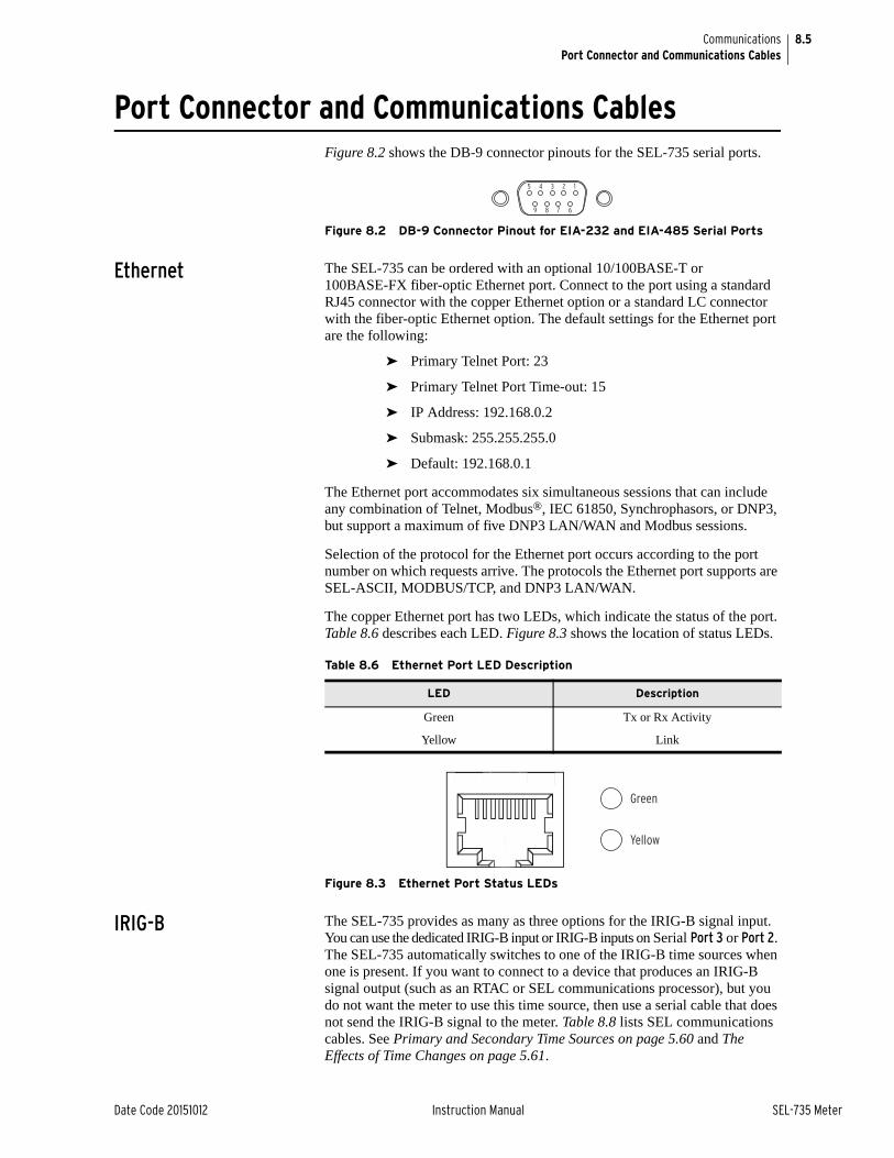
8.5
Date Code 20151012 Instruction Manual SEL-735 Meter
CommunicationsPort Connector and Communications Cables
Port Connector and Communications CablesFigure 8.2 shows the DB-9 connector pinouts for the SEL-735 serial ports.
Figure 8.2 DB-9 Connector Pinout for EIA-232 and EIA-485 Serial Ports
Ethernet The SEL-735 can be ordered with an optional 10/100BASE-T or 100BASE-FX fiber-optic Ethernet port. Connect to the port using a standard RJ45 connector with the copper Ethernet option or a standard LC connector with the fiber-optic Ethernet option. The default settings for the Ethernet port are the following:
➤ Primary Telnet Port: 23
➤ Primary Telnet Port Time-out: 15
➤ IP Address: 192.168.0.2
➤ Submask: 255.255.255.0
➤ Default: 192.168.0.1
The Ethernet port accommodates six simultaneous sessions that can include any combination of Telnet, Modbus®, IEC 61850, Synchrophasors, or DNP3, but support a maximum of five DNP3 LAN/WAN and Modbus sessions.
Selection of the protocol for the Ethernet port occurs according to the port number on which requests arrive. The protocols the Ethernet port supports are SEL-ASCII, MODBUS/TCP, and DNP3 LAN/WAN.
The copper Ethernet port has two LEDs, which indicate the status of the port. Table 8.6 describes each LED. Figure 8.3 shows the location of status LEDs.
Figure 8.3 Ethernet Port Status LEDs
IRIG-B The SEL-735 provides as many as three options for the IRIG-B signal input. You can use the dedicated IRIG-B input or IRIG-B inputs on Serial Port 3 or Port 2. The SEL-735 automatically switches to one of the IRIG-B time sources when one is present. If you want to connect to a device that produces an IRIG-B signal output (such as an RTAC or SEL communications processor), but you do not want the meter to use this time source, then use a serial cable that does not send the IRIG-B signal to the meter. Table 8.8 lists SEL communications cables. See Primary and Secondary Time Sources on page 5.60 and The Effects of Time Changes on page 5.61.
5 4 3 2 1
9 8 7 6
Table 8.6 Ethernet Port LED Description
LED Description
Green Tx or Rx Activity
Yellow Link
Green
Yellow

8.6
SEL-735 Meter Instruction Manual Date Code 20151012
CommunicationsCommunications Protocols
Serial Port Pinouts
SEL-735 Communications Cables
Table 8.8 shows several types of SEL serial communications cables that connect the SEL-735 to other devices. Cables marked with 'R' indicate that the cable may be ruggedized. These and other cables are available from SEL. Please use the SEL-5801 SEL Cable Selector program for more information on SEL cables, including the pinouts of cables.
For long-distance communications as many as 80 kilometers and for electrical isolation of communications ports, use the SEL-2800 family of fiber-optic transceivers. Contact SEL for more details on these devices.
Communications ProtocolsSoftware Protocols SEL-735 communications protocols:
➤ SEL ASCII
➤ SEL Distributed Port Switch Protocol (LMD)
➤ SEL Fast Meter
➤ SEL Compressed ASCII
➤ IEC 61850 (Optional)
➤ MV-90 Translation
➤ Modbus® RTU
➤ Modbus® TCP
Table 8.7 Port Pinout Functions
Pin EIA-232 Port 2, Port 3 EIA-232 Port F, 4C EIA-485 Port 3, Port 4A
1 +5 Vdc N/C +TX
2 RXD RXD –TX
3 TXD TXD +RX
4 +IRIG-B N/C –RX
5 GND GND SHIELD
6 –IRIG-B N/C N/C
7 RTS RTS N/C
8 CTS CTS N/C
9 GND GND N/C
Table 8.8 SEL-735 Communications Cables
Communications Type
FunctionSEL Cable
DesignationIRIG-B
Support?
Serial SEL-735 to PC, DB-9 Serial C234A [R] No
C235 No
C287 [R] No
SEL-735 to PC, Optical Probe
C660 (DB-9) No
C661 (USB) No
SEL-735 to other IED C273A [R] Yes
Ethernet SEL-735 to PC or other IED
C627 [R] No
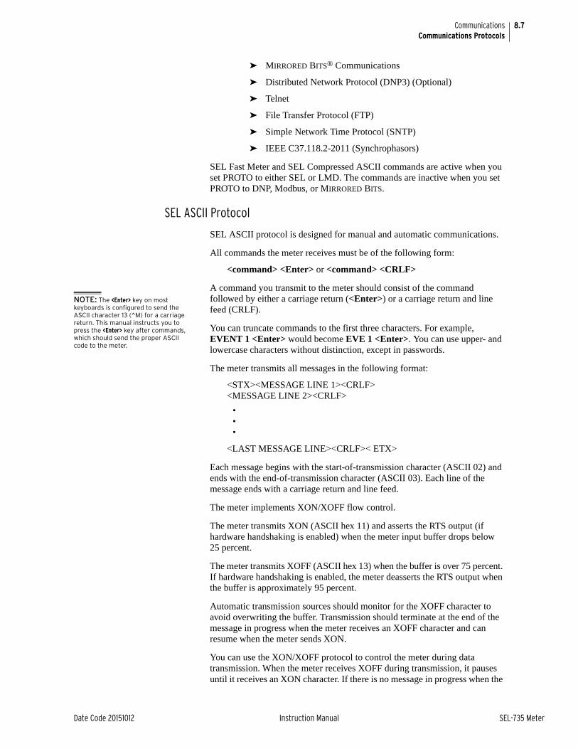
8.7
Date Code 20151012 Instruction Manual SEL-735 Meter
CommunicationsCommunications Protocols
➤ MIRRORED BITS® Communications
➤ Distributed Network Protocol (DNP3) (Optional)
➤ Telnet
➤ File Transfer Protocol (FTP)
➤ Simple Network Time Protocol (SNTP)
➤ IEEE C37.118.2-2011 (Synchrophasors)
SEL Fast Meter and SEL Compressed ASCII commands are active when you set PROTO to either SEL or LMD. The commands are inactive when you set PROTO to DNP, Modbus, or MIRRORED BITS.
SEL ASCII Protocol
SEL ASCII protocol is designed for manual and automatic communications.
All commands the meter receives must be of the following form:
<command> <Enter> or <command> <CRLF>
A command you transmit to the meter should consist of the command followed by either a carriage return (<Enter>) or a carriage return and line feed (CRLF).
You can truncate commands to the first three characters. For example, EVENT 1 <Enter> would become EVE 1 <Enter>. You can use upper- and lowercase characters without distinction, except in passwords.
The meter transmits all messages in the following format:
<STX><MESSAGE LINE 1><CRLF><MESSAGE LINE 2><CRLF>
•••
<LAST MESSAGE LINE><CRLF>< ETX>
Each message begins with the start-of-transmission character (ASCII 02) and ends with the end-of-transmission character (ASCII 03). Each line of the message ends with a carriage return and line feed.
The meter implements XON/XOFF flow control.
The meter transmits XON (ASCII hex 11) and asserts the RTS output (if hardware handshaking is enabled) when the meter input buffer drops below 25 percent.
The meter transmits XOFF (ASCII hex 13) when the buffer is over 75 percent. If hardware handshaking is enabled, the meter deasserts the RTS output when the buffer is approximately 95 percent.
Automatic transmission sources should monitor for the XOFF character to avoid overwriting the buffer. Transmission should terminate at the end of the message in progress when the meter receives an XOFF character and can resume when the meter sends XON.
You can use the XON/XOFF protocol to control the meter during data transmission. When the meter receives XOFF during transmission, it pauses until it receives an XON character. If there is no message in progress when the
NOTE: The <Enter> key on most keyboards is configured to send the ASCII character 13 (^M) for a carriage return. This manual instructs you to press the <Enter> key after commands, which should send the proper ASCII code to the meter.

8.8
SEL-735 Meter Instruction Manual Date Code 20151012
CommunicationsCommunications Protocols
meter receives XOFF, it blocks transmission of any message arriving at its buffer. The meter will again accept messages after it receives an XON character.
The CAN character (ASCII hex 18) aborts a pending transmission. This is useful in terminating an unwanted transmission.
You can send control characters from most keyboards with the following keystrokes:
IEC 61850 Protocol The meter optionally supports IEC 61850 protocol, including GOOSE and MMS, as described in Appendix H: IEC 61850 Communications. The IEC 61850 protocol is only available on meters with an Ethernet port.
SEL Distributed Port Switch Protocol (LMD)The SEL Distributed Port Switch Protocol (LMD) permits multiple SEL meters to share a common communications channel. Select the protocol by setting the port setting PROTO = LMD.
SEL Fast Meter ProtocolSEL Fast Meter protocol supports binary messages to transfer metering and control messages. Appendix C: SEL Communications Processors describes this protocol.
SEL Compressed ASCII ProtocolSEL Compressed ASCII protocol provides compressed versions of some of the meter ASCII commands. Appendix C: SEL Communications Processors describes this protocol.
MV-90 TranslationThe meter provides MV-90 support via SEL ASCII protocol.
Modbus RTUThe meter provides Modbus RTU support. Appendix E: Modbus Communications Protocol describes the Modbus protocol.
MIRRORED BITS CommunicationsThe SEL-735 supports MIRRORED BITS meter-to-meter communications on two ports simultaneously. See Appendix F: MIRRORED BITS Communications.
Distributed Network Protocol (DNP3)The meter provides Distributed Network Protocol (DNP3) Level 2 Slave support. Appendix D: Distributed Network Protocol describes the optional DNP protocol.
XON: <Ctrl+Q>XOFF: <Ctrl+S>CAN: <Ctrl+X>

8.9
Date Code 20151012 Instruction Manual SEL-735 Meter
CommunicationsCommunications Protocols
TelnetThe SEL-735 provides Telnet support via the Ethernet port (PORT 1). The meter supports a total of six simultaneous sessions on this port (see Ethernet on page 8.5).
FTPThe SEL-735 provides FTP support via the Ethernet port (PORT 1). The meter supports one FTP session. See File Transfer Protocol (FTP) and MMS File Transfer.
SNTPThe SEL-735 provides SNTP support via the Ethernet port (PORT 1). See Simple Network Time Protocol (SNTP).
IEEE C37.118.1 Synchrophasors
The SEL-735 provides Synchrophasor support via the Ethernet port (PORT 1). The meter supports two Synchrophasor sessions. See Appendix I: Synchrophasors.
Hardware Protocol, RTS/CTS Handshaking
The EIA-232 serial port supports request to send/clear to send (RTS/CTS) hardware handshaking. EIA-485 Serial Port 4A provides no support for RTS/CTS handshaking.
To enable hardware handshaking, set RTSCTS for the port to Yes. Set RTSCTS = N to disable hardware handshaking.
If RTSCTS = N, the meter permanently asserts the RTS line.
If RTSCTS = Y, the meter deasserts RTS when it is unable to receive characters.
If RTSCTS = Y, the meter does not send characters until the CTS input is asserted.
Port Automatic Messages
When the serial port AUTO setting is Y, the meter sends automatic messages to indicate specific conditions. Table 8.9 describes the automatic messages.
Table 8.9 Serial Port Automatic Messages
Condition Description
Power Up The meter sends a message containing the present date and time, meter and terminal identifiers, and the Access Level 0 prompt when you turn on the meter.
Event Trigger The meter sends an event summary for each triggering of an event report. See Waveform Capture Event Reports on page 6.6.
Self-Test Warning or Failure
The meter sends a status report each time it detects a self-test warn-ing or failure condition. See Meter Self-Tests on page 9.16.

8.10
SEL-735 Meter Instruction Manual Date Code 20151012
CommunicationsCommunications Protocols
Port Access Levels You can issue commands to the meter via the serial port or via a Telnet connection on the Ethernet port to view metering values, change meter settings, etc. As SEL-735 Meter Command Summary shows, you can access a listing of available port commands only from the corresponding access level. The access levels are as follows:
➤ Access Level 0 (the lowest access level)
➤ Access Level 1
➤ Access Level E
➤ Access Level 2 (the highest access level)
➤ Access Level C (use only when directed by SEL)
Again, a higher access level can access the port commands in a lower access level. The manual shows the commands in uppercase letters, but you can also enter these commands with lowercase letters.
Access Level 0
Once you have established port communications with the meter, you can enter Access Level 0. The meter sends the following prompt at Access Level 0:
=
Enter the ACC command at the Access Level 0 prompt to move to Access Level 1. The following text shows an example of the ACC command.
=ACC <Enter>
Access Level 1
When the meter is in Access Level 1, the meter sends the following prompt:
=>
Enter the 2AC command at Access Level 1 to move to Access Level 2. The following text shows an example of the 2AC command.
=>2AC <Enter>
Enter the EAC command at Access Level 1 to move to Access Level E. The following text shows an example of the EAC command.
=>EAC <Enter>
Access Level E
When the meter is in Access Level E, the meter sends the following prompt:
E=>

8.11
Date Code 20151012 Instruction Manual SEL-735 Meter
CommunicationsCommunications Protocols
Access Level 2
When the meter is in Access Level 2, the meter sends the following prompt:
=>>
Any of the Access Level 1 and Access Level E commands are also available in Access Level 2.
Access Level C
The CAL access level is intended for use by the SEL factory and by SEL field service personnel to help diagnose troublesome installations. A list of commands available at the CAL level is available from SEL upon request. Do not enter the CAL access level, except as directed by SEL.
File Transfer Protocol (FTP) and MMS File Transfer
File Transfer Protocol (FTP) is a standard protocol for exchanging files between computers over a TCP/IP network. The SEL-735 operates as an FTP server, presenting files to FTP clients. The meter supports one FTP session at a time. Requests to establish additional FTP sessions are denied. Manufacturing Messaging Specification (MMS) is used in IEC 61850 applications and provides services for the transfer of real-time data, including files, within a substation LAN.
File Structure
The file structure is organized as a directory and subdirectory tree similar to that used by Windows and other common operating systems. The files and folder structure available over the FTP and MMS File Transfer interface is different from the files and folder structure available to the FIL command. The file structure described here applies to the FTP and MMS interfaces. The SEL-735 root directory contains the CFG.TXT file and an ERR.TXT file, the SET_61850.CID file (see Appendix H: IEC 61850 Communications), a CFG.XML file, a SETTINGS directory, an EVENTS/COMTRADE directory, and a REPORTS directory.
The SETTINGS directory contains the same settings files available using the FIL command.
The EVENTS/COMTRADE directory contains event files. On the FTP interface, it is named EVENTS. On the MMS interface, it is named COMTRADE.
The REPORTS directory contains an LDP file for each of the LDP recorders, for each of the following time frames:
➤ Last 24 Hours
➤ Last 7 Days
➤ Last 30 Days
➤ Last 6 Months
➤ All
The SET_61850.CID file defines the IEC 61850 data sets for the meter. Read and write access is available over FTP only; the file is not available to the MMS interface.

8.12
SEL-735 Meter Instruction Manual Date Code 20151012
CommunicationsCommunications Protocols
Access Control
To log in to the server, enter the value of the Port 1 setting FTPUSER as the user name in your FTP application. Enter the Level 2 password as the password in your FTP application. Note that FTP does not encrypt passwords before sending them to the server.
MMS is enabled when Port 1 setting E61850 is set to 1 or higher. MMS authentication is supported, see MMS on page H.4
Using FTP and MMS
A free FTP application is included with most web browser software and PC operating systems. Once you have retrieved the necessary files, be sure to close the FTP connection by using the disconnect function of your FTP application or by completely closing the application. Failure to do so can cause the FTP connection to remain open, which blocks subsequent connection attempts until FTPIDLE time expires.
See Appendix H: IEC 61850 Communications for information about using MMS.
Simple Network Time Protocol (SNTP)
When ESNTP is enabled (Port 1 setting ESNTP is not OFF), the meter internal clock synchronizes to the time of day served by a Network Time Protocol (NTP) server. The meter uses a simplified version of NTP called the Simple Network Time Protocol (SNTP). SNTP is a secondary time source (see Primary and Secondary Time Sources on page 5.60).
SNTP as Main or Backup Time Source
If an IRIG-B time source is connected and either Device Word bits TSOK or TIRIG assert, then the meter synchronizes the internal time-of-day clock to the incoming IRIG-B time code signal, even if SNTP is configured in the meter and an NTP server is available. If the IRIG-B source is disconnected (TIRIG deassert) then the meter synchronizes the internal time-of-day clock to the NTP server if available. In this way an NTP server acts as either the main time source, or as a backup time source to the more accurate IRIG-B time source.
Creating an NTP Server
Three SEL application notes available from the SEL website describe how to create an NTP server.
AN2009-10: Using an SEL-2401, SEL-2404, or SEL-2407® to Serve NTP Via the SEL-3530 RTAC
AN2009-38: Using SEL Satellite-Synchronized Clocks With the SEL-3332 or SEL-3354 to Output NTP
AN2010-03: Using an SEL-2401, SEL-2404, or SEL-2407 to Create a Stratum 1 Linux® NTP Server
Configuring SNTP Client in the Meter
To enable SNTP in the meter make Port 1 setting ESNTP = UNICAST, MANYCAST, or BROADCAST. Table 8.10 shows each setting associated with SNTP.

8.13
Date Code 20151012 Instruction Manual SEL-735 Meter
CommunicationsCommunications Protocols
SNTP Operation Modes
The following sections explain the setting associated with each SNTP operation mode (UNICAST, MANYCAST, and BROADCAST).
ESNTP = UNICAST
In unicast mode of operation the SNTP client in the meter requests time updates from the primary (IP address setting SNTPPIP) or backup (IP address setting SNTPBIP) NTP server at a rate defined by setting SNTPRAT. If the NTP server does not respond with the period defined by the sum of setting SNTPTO and SNTPRAT then the meter tries the other SNTP server. When the meter successfully synchronizes to the primary NTP time server, Device Word bit TSNTPP asserts. When the meter successfully synchronizes to the backup NTP time server, Relay Word bit TSNTPB asserts.
ESNTP = MANYCAST
In manycast mode of operation the meter initially sends an NTP request to the broadcast address contained in setting SNTPPIP. The meter continues to broadcast requests at a rate defined by setting SNTPRAT. When a server replies, the meter sets that server as the primary NTP server, and switches to UNICAST mode, asserts Relay Word bit TSNTPP, and thereafter requests updates from the primary server. If the NTP server stops responding for time SNTPTO, the meter deasserts TSNTPP and begins to request time from the broadcast address again until a server responds.
ESNTP = BROADCAST
Setting SNTPPIP = 0.0.0.0 while ESNTP = BROADCAST, the meter will listen for and synchronize to any broadcasting NTP server. If setting SNTPPIP is set to a specific IP address while setting ESNTP = BROADCAST, then the
Table 8.10 Settings Associate With SNTP
Setting Prompt Range Default Description
ESNTP SNTP Enable (OFF, UNI-CAST, MANYCAST, BROADCAST)
UNICAST, MANYCAST, BROADCAST
OFF Selects the mode of operation of SNTP. See descriptions in SNTP Operation Modes.
SNTPRATa
a This setting is: Hidden if ESNTP = OFF; Hidden and forced to 5 if ESNTP = BROADCAST.
SNTP Request Update Rate (15–3600 s)
15–3600 s 60 Determines the rate at which the meter asks for updated time from the NTP server when
ESNTP = UNICAST or MANYCAST. Deter-mines the time the meter will wait for an NTP broadcast when ENSTP = BROADCAST.
SNTPTO SNTP Timeout (5–20 s) 5–20 s 5 Determines the time the meter will wait for the NTP master to respond when ENSTP = UNI-CAST or MANYCAST
SNTPPIP SNTP Primary Server IP Address (w.x.y.z)b
b Where: w: 0–126, 128–239, x: 0–255, y: 0–255, z: 0–255
Valid IP Address 192.168.1.110 Selects primary NTP server when
ENSTP = UNICAST, or broadcast address when ESNTP = MANYCAST or BROAD-CAST
SNTPBIP SNTP Backup Server IP Address (w.x.y.z)c
c Where: w: 0–126, 128–223, x: 0–255, y: 0–255, z: 0–255
Valid IP Address 192.168.1.111 Selects backup NTP server when ESNTP = UNICAST.
SNTPPORd
d This setting is hidden if ESNTP ≠ UNICAST.
SNTP IP Local Port Number (1–65534)
1–65534 123 Ethernet port used by SNTP. Leave at default value unless otherwise required.

8.14
SEL-735 Meter Instruction Manual Date Code 20151012
CommunicationsCommand Summary
meter will listen for and synchronize to only NTP server broadcasts from that address. When synchronized the meter asserts Relay Word bit TSNTPP. Relay Word bit TNSTPP deasserts if the meter does not receive a valid broadcast within the SNTPT0 setting value after the period defined by setting SNTPRAT.
SNTP Accuracy Considerations
SNTP time synchronization accuracy is limited by the accuracy of the SNTP Server and by the networking environment. The highest degree of SNTP time synchronization can be achieved by minimizing the number of switches and routers between the SNTP Server and the meter.
When installed on a network with low traffic, configured with one Ethernet switch between the meter and the SNTP server, and when using ESNTP = UNICAST or MANYCAST, the meter time synchronization error to the SNTP server is typically less than ±5 milliseconds.
Command SummaryThe Command Summary on page 8.14 lists the serial port commands alphabetically in the associated required access level.
Much of the information available from the serial port commands is also available via the front-panel pushbuttons. See Section 3: Front-Panel Operation for more information on the front-panel pushbuttons.
The commands at the different access levels offer varying levels of control.
➤ The Access Level 1 commands allow you to look at information only (settings, metering, etc.), but not to change it.
➤ The Access Level E commands allow you to reset meter registers, including peak demand.
➤ The Access Level 2 commands allow you to change meter settings.
The meter responds with Invalid Access Level if you enter a command from an access level lower than the specified access level for the command. The following example shows how the meter responds to commands not in the previous listing or which you have entered incorrectly.
Invalid Command
Many of the command responses display the following header:
FEEDER 1 Date: 01/01/02 Time: 00:01:07.175STATION A Time Source: int
➤ FEEDER 1: This is the MID setting (the meter ships with the default setting MID = FEEDER 1.
➤ STATION A: This is the TID setting (the meter ships with the default setting TID = STATION A.

8.15
Date Code 20151012 Instruction Manual SEL-735 Meter
CommunicationsCommand Explanations
➤ Date: This is the date the meter provided the command response (except for meter response to the EVE [Event] command, where it is the date the event occurred). You can modify the date display format by changing the DATE_F meter global setting.
➤ Time: This is the time the meter responded to the command (except for meter response to the EVE command, where it is the time the event occurred).
➤ Time Source: This is the time source status at the time of the command response (except for the meter response to EVE command, where it is the time source status at the time the event occurred).
For a list of all the available commands from a terminal prompt with the required access level, refer to SEL-735 Meter Command Summary; for more details on each command, please contact the SEL factory.
Command ExplanationsFIL Command The FILE command uses Y-modem transfer protocol to provide an efficient
means of transferring files between the meter and a PC. Software applications, such as ACSELERATOR QuickSet® SEL-5030 Software, use the FILE commands to transfer settings files to and from the meter.
Below is a sample of the FILE DIR command response.
=>>FILE DIR <Enter>
EVENTS R D ASCII R ZASCII R DIAGNOSTICS.TXT R DIAGNOSTICS.ZTXT R SET_ALL.TXT R CFG.TXT R ERR.TXT R SET_PF.TXT RW SET_P2.TXT RW SET_P3.TXT RW SET_P1.TXT RW SET_1.TXT RW SET_F.TXT RW SET_L.TXT RW SET_R.TXT RW SET_E.TXT RW SET_CFG.TXT RW SET_D.TXT RW SET_TOU.TXT RW LDP1_DATA.BIN R LDP1_DATA.TXT R LDP1_DATA.ZBIN R LDP2_DATA.BIN R LDP2_DATA.TXT R LDP2_DATA.ZBIN R LDP3_DATA.BIN R
Command Description Access Level
FILE DIR Return a list of files. 1
FILE READ filename
Transfer settings file filename from the meter to the PC.
1
FILE WRITE filename
Transfer settings file filename from the PC to the meter.
2
FILE SHOW filename
Displays contents of the file filename. 1

8.16
SEL-735 Meter Instruction Manual Date Code 20151012
CommunicationsCommand Explanations
LDP3_DATA.TXT R LDP3_DATA.ZBIN R LDP4_DATA.BIN R LDP4_DATA.TXT R LDP4_DATA.ZBIN R LDP5_DATA.BIN R LDP5_DATA.TXT R LDP5_DATA.ZBIN R LDP6_DATA.BIN R LDP6_DATA.TXT R LDP6_DATA.ZBIN R LDP7_DATA.BIN R LDP7_DATA.TXT R LDP7_DATA.ZBIN R LDP8_DATA.BIN R LDP8_DATA.TXT R LDP8_DATA.ZBIN R LDP9_DATA.BIN R LDP9_DATA.TXT R LDP9_DATA.ZBIN R LDP10_DATA.BIN R LDP10_DATA.TXT R LDP10_DATA.ZBIN R LDP11_DATA.BIN R LDP11_DATA.TXT R LDP11_DATA.ZBIN R LDP12_DATA.BIN R LDP12_DATA.TXT R LDP12_DATA.ZBIN R
GOO Command Use the GOOSE command to display transmit and receive GOOSE messaging and statistics information, which can be used for troubleshooting. The GOOSE command variants and options are shown below.
The information displayed for each GOOSE IED is described in the following table.
Command Variant DescriptionAccess Level
GOO Display GOOSE information. 1
GOO k Display GOOSE information k times. 1
GOO S Display a list of GOOSE subscriptions with their ID. 1
GOO S n Display GOOSE statistics for subscription ID n. 1
GOO S ALL Display GOOSE statistics for all subscriptions. 1
GOO S n L Display GOOSE statistics for subscription ID n including error history.
1
GOO S ALL L Display GOOSE statistics for all subscriptions including error history.
1
GOO S n C Clear GOOSE statistics for subscription ID n. 1
GOO S ALL C Clear GOOSE statistics for all subscriptions. 1
Information Field Description
TransmitGOOSE Control Reference
This field represents the GOOSE control reference information that includes the IED name, ldInst (Logical Device Instance), LN0 lnClass (Logical Node Class), and GSEControl name (GSE Control Block Name) (e.g., SEL_735CFG/LLN0$GO$GooseDSet13).
ReceiveGOOSE Control Reference
This field represents the goCbRef (GOOSE Control Block Reference) information that includes the iedName (IED name), ldInst (Logical Device Instance), LN0 lnClass (Logical Node Class), and cbName (GSE Control Block Name) (e.g., SEL_735CFG/LLN0$GO$GooseDSet13).
MultiCastAddr (Multicast Address)
This hexadecimal field represents the GOOSE multicast address.
Ptag This three-bit decimal field represents the priority tag value, where spaces are used if the priority tag is unknown.

8.17
Date Code 20151012 Instruction Manual SEL-735 Meter
CommunicationsCommand Explanations
Vlan This 12-bit decimal field represents the virtual LAN (Local Area Network) value, where spaces are used if the virtual LAN is unknown.
StNum (State Number) This hexadecimal field represents the state number that increments with each state change.
SqNum (Sequence Number) This hexadecimal field represents the sequence number that increments with each retransmitted GOOSE message sent.
TTL (Time to Live) This field contains the time (in ms) before the next message is expected.
Code When appropriate, this text field contains warning or error condition text that is abbreviated as follows:
Transmit Data Set Reference
This field represents the DataSetReference (Data Set Reference) that includes the IED name, LN0 lnClass (Logical Node Class), and GSEControl datSet (Data Set Name) (e.g., SEL_735/LLN0$DSet13).
Receive Data Set Reference
This field represents the datSetRef (Data Set Reference) that includes the iedName (IED name), ldInst (Logical Device Instance), LN0 lnClass (Logical Node Class), and datSet (Data Set Name) (e.g., SEL_735/LLN0$DSet13).
Ctrl Ref/ControlBlockReference
This is the GOOSE control block reference. It is a concatenation of the logical device name, LLN0 (logical node containing the control block), GO (functional constraint), and the GSECon-trol name. (e.g. SEL_753_1CFG/LLN0$GO$GooseDSet13)
AppID This is the application identifier as a decimal number.
From This is the date and time the current statistics collection started.
To This is the date and time the GOOSE statistics command was executed.
Accumulated downtime duration
This represents the total amount of time a subscription was in an error state. The duration is dis-played in the format: hhhh:mm:ss.zzz.
Maximum downtime duration This represents the maximum amount of time a subscription was continuously in error state. The duration is displayed in the format: hhhh:mm:ss.zzz.
Date & time maximum down-time began
This is the date and time the recorded maximum downtime started.
Number of messages received out-of-sequence (OOS)
This represents the total number of messages received with either the state number and/or sequence number out-of-sequence. This includes cases where more than one instance of a mes-sage is received within a single meter processing interval. In this case, the most recent message is processed and the others are discarded.
Number of time-to-live (TTL) violations detected
This represents the total number of times a message was not received within the expected period/interval.
Number of messages incor-rectly encoded or cor-rupted
This represents the total number of messages that were identified with this subscription but were either incorrectly encoded or encoded with an incorrect dataset.
Number of messages lost due to receive overflow
This represents the total number of messages that were not processed because memory resources were exhausted. This includes cases where more than one instance of a message is received within a single meter processing interval. In this case, the most recent message is pro-cessed and the others are discarded.
Information Field Description
Code Abbreviation Explanation
OUT OF SEQUENC Out-of-sequence error
CONF REV MISMA Configuration Revision mismatch
NEED COMMISSIO Needs Commissioning
TEST MODE Test Mode
MSG CORRUPTED Message Corrupted
TTL EXPIRED Time to live expired

8.18
SEL-735 Meter Instruction Manual Date Code 20151012
CommunicationsCommand Explanations
An example response to the GOOSE commands is shown in Figure 8.4.
#>GOOSE <Enter>
GOOSE Transmit Status MultiCastAddr Ptag:Vlan AppID StNum SqNum TTL Code-----------------------------------------------------------------------------SEL_735_DevCFG/LLN0$GO$goose_1 01-0C-CD-01-00-07 4:3 7 1 16 792 Data Set: SEL_735_DevCFG/LLN0$GOOSE_out_1
SEL_735_DevCFG/LLN0$GO$goose_2 01-0C-CD-01-00-0A 4:3 10 1 16 632 Data Set: SEL_735_DevCFG/LLN0$GOOSE_out_2
GOOSE Receive Status MultiCastAddr Ptag:Vlan AppID StNum SqNum TTL Code-----------------------------------------------------------------------------SEL_735_MonCFG/LLN0$GO$GOOSE_msg_1 01-0C-CD-01-00-05 : 5 101 0 0 2000 Data Set: SEL_735_MonCFG/LLN0$goose_1_1
=>>GOOSE S 1 L SubsID 1----------------------------------------------------------------------------- Ctrl Ref: SEL_735_MonCFG/LLN0$GO$GOOSE_msg_1 AppID : 5 From : 05/30/2013 12:06:38.734 To: 05/30/2013 12:07:47.434
Accumulated downtime duration : 0000:01:08.690 Maximum downtime duration : 0000:01:08.690 Date & time maximum downtime began : 05/30/2013 12:06:38.742 Number of messages received out-of-sequence(OOS) : 0 Number of time-to-live(TTL) violations detected : 1 Number of messages incorrectly encoded or corrupted: 0 Number of messages lost due to receive overflow : 0 Calculated max. sequential messages lost due to OOS: 0 Calculated number of messages lost due to OOS : 0
# Date Time Duration Failure 1 05/30/2013 12:06:38.742 0000:01:08.690 TTL EXPIRED
=>
Figure 8.4 GOOSE Command Response
TEST DB Command Use the TEST DB command to temporarily force the meter to send fixed analog and/or digital values over IEC 61850 (GOOSE and MMS) for protocol testing.
Calculated max. sequen-tial messages lost due to OOS
This represents the maximum estimated number of messages that were missed after receiving a message with a higher state or sequence number than expected.
Calculated number of mes-sages lost due to OOS
This represents the total of all estimated number of messages lost as a result of state or sequence number skip in received messages.
Information Field Description
Command Description Access Level
TEST DB Display the present status of digital and analog overrides. 2
TEST DB A name value
Force protocol analog element name to override value. 2
TEST DB D name value
Force protocol digital element name to override value.
2
TEST DB name OFF
Clear (analog or digital) override for element name. 2
TEST DB OFF Clear all analog and digital overrides. 2

8.19
Date Code 20151012 Instruction Manual SEL-735 Meter
CommunicationsCommand Explanations
The TEST DB command provides a method to override Device Word bits or analog values to aid testing of communications interfaces. The command overrides values in the IEC 61850 communications interface only. The actual values used by the meter for metering and control are not changed. However, remote devices may use these analog and digital signals to make control decisions. Ensure that remote devices are properly configured to receive the overridden data before using the TEST DB command.
To override analog data in a communications interface, enter the following from Access Level 2 or higher.
=>>TEST DB A name value <Enter>
where value is a numerical value and name is an analog label from Table H.13–Table H.15 (IEC 61850).
For example, the TEST DB command can be used to force the value of Phase A current magnitude transmitted to a remote device to 100 amperes.
=>>TEST DB A IA 100 <Enter>
To override digital data in an IEC 61850 communications interface, enter the following from Access Level 2 or higher.
=>>TEST DB D name value <Enter>
where name is a Device Word bit (see Table G.24) and value is 1 or 0.
For example, if Device Word bit SAGA = logical 0, the TEST DB command can be used to effectively force the communicated status of this Device Word bit to logical 1 to test the communications interface.
=>>TEST DB D SAGA 1 <Enter>
When the meter is not in Test DB Mode, the meter responds to either the digital or analog override request with the following message.
WARNING: TEST MODE is not a regular operation.Communication outputs of the device will be overridden by simulated values.
Are you sure (Y/N)? Y <Enter>
The meter responds as follows.
Test Mode Active. Use Test DB OFF command to exit Test Mode.
Override Added
Device Word bit TESTDB will also assert to indicate that Test DB Mode is active. If the meter is already in Test DB Mode (overrides are already active), the meter responds as follows.
Override Added
! WARNINGTo reduce the chance of a false operating decision when using the TEST DB command, ensure that protocol master device(s) flag the data as “forced or test data.” One possible method is to monitor the TESTDB Device Word bit.
NOTE: When using the TEST DB command to generate values for Fast Meter testing, you may need to override all current and voltage angles (IAFA, VAFA, etc.) to ensure the expected phase relationship.
NOTE: When using the TEST DB command, specifying a negative value may yield an unexpected display in some instances.

8.20
SEL-735 Meter Instruction Manual Date Code 20151012
CommunicationsCommand Explanations
The TEST DB command alone displays the present status of digital and analog overrides. An example TEST DB response after two analogs follows.
==>TEST DB <Enter>
SEL-735 Date: 10/15/10 Time: 16:24:38.764STATION A
NAME OVERRIDE VALUEIA 100.0000FREQ 60.0000
==>
Individual overrides are cleared using the TEST DB command with the OFF parameter.
=>>TEST DB D or A name OFF <Enter>
Entering TEST DB OFF without name will clear all overrides. The meter will automatically exit Test DB Mode and clear all overrides if there are no TEST DB commands entered for 30 minutes.

Date Code 20151012 Instruction Manual SEL-735 Meter
SEL-735 Meter Command Summary
Access Level
Command Description
0 ACC Move to Access Level 1
0 BNA Binary names
0 CAS Compressed ASCII data configuration
0 DNA Compressed names
0 EXI Terminate a Telnet session. Only available when connected via Telnet.
0 ID Compressed ASCII Fast Meter ID
0 QUI Quit to Access Level 0
0 SNS Compressed SER settings
1 2AC Move to Access Level 2
1 CEV Compressed event report, 16 samples per cycle
1 COM Display MIRRORED BITS channel statistics
1 COM C Reset MIRRORED BITS channel statistics
1 COU Display SELOGIC counters
1 CHI Compressed history
1 CCR Compressed calibration error report
1 CST Compressed status
1 CTR C [A] Comtrade format event report, config
1 CTR D [A] Comtrade format event report, data
1 DAT Show date
1 DNP[n] Show DNP map
1 EAC Move to Energy Access Level
1 EVE Latest event report, 16 samples per cycle
1 EVE C Compressed event report
1 EVE D 1/16-cycle resolution Device Word bit data
1 EVE L, EVE R Raw, unfiltered event report
1 EVE M 1/16-cycle resolution MIRRORED BITS data
1 FIL DIR List all device files and directories
1 FIL READ Transfer settings and other files from meter
1 FIL SHOW Display file contents
1 GOO Display GOOSE transmit and receive information
1 HIS Summary event reports
1 LDP[n] Display report for load profile recorder, where n is the LDP recorder number
1 MAT Displays results of SELOGIC math variable equations
1 MET Display instantaneous metering data
1 MET A Display aggregated values
1 MET AI Display analog input voltage
1 MET CF Display crest factor quantities

2
SEL-735 Meter Instruction Manual Date Code 20151012
SEL-735 Meter Command Summary
1 MET CFG Display configurable registers values
1 MET D Display compensated demand data
1 MET D P Display compensated peak demand data
1 MET D P U Display uncompensated peak demand data
1 MET D T Display the timestamps of the peak demands
1 MET D T U Display the timestamps of the uncompensated peak demands
1 MET D U Display uncompensated demand data
1 MET E Display energy data
1 MET FL Display flicker data
1 MET H Display harmonic data
1 MET L Display losses
1 MET M Display maximum and minimum values
1 MET PM Display Synchrophasor Data
1 MET PM time Display Synchrophasor Data at time time
1 MET PM HIS Display the most recently captured MET PM report
1 MET RMS Display rms metering data
1 QUI Quit to Access Level 0
1 SER Display Sequential Events Recorder records
1 SHO Display settings
1 SSI Display voltage sag/swell/interruption (VSSI) report
1 STA Display self-test status
1 STA E Display EEPROM messages
1 TAR Display Device Word bits
1 TIM Show time
1 TOG Resets NEWEVNT Device Word bit
1 TRI Trigger an event
1 VER Display version and configuration information
E DAT date Set date
E LDP[n] C Reset load profile recorder, where n is the LDP recorder number
E MET CF R Clear crest factor metering
E MET M R Clear max/min metering
E MET P R Clear peak demand metering
E QUI Quit to Access Level 0
E TIM time Set time
2 CAL Go to Access Level C
2 CON x Control remote bits x
2 DNP[n] Show DNP map
2 FIL WRITE Write setting files to the meter
2 FOR Change meter form
2 HIS C Clear event and history records
2 L_D Load new firmware
Access Level
Command Description

3
Date Code 20151012 Instruction Manual SEL-735 Meter
SEL-735 Meter Command Summary
2 LOO Initiate/clear MIRRORED BITS loopback
2 MET D R Clear demand metering
2 MET E R Reset energy metering
2 MET FL R Reset flicker metering quantities
2 MET P R Clear peak demand metering
2 MEM Display memory
2 PAR Display or modify the part number
2 PAS Set/show passwords
2 PUL Pulse output contact
2 QUI Quit to Access Level 0
2 R_S Restore factory settings
2 SER [R] Display or clear SER
2 SET Change settings
2 SSI C Clear SSI data (including SSI summary) from the meter
2 SSI R Reset SSI processing
2 SSI S Display SSI summary report
2 SSI T Trigger an event and store SSI data.
2 TES AGG Capture and display 10/12-cycle data
2 TEST DB A name value
Override analog label name with value in communications interface
2 TEST DB D name value
Override Device Word bit name with value in communications interface, where value = 0 or 1
2 TEST MODE Display Test Mode parameters
2 VER Display version and configuration information
SB BAU rate Set baud rate to 300, 1200, 2400, 4800, 9600, 19200, 38400 (57600 or 115200 if Port 2 or Port 3) bps.
SB BFI Display the SELBOOT version.
SB ERA Erase the existing firmware.
SB EXI Exit this program and restart the device.
SB FID Display the firmware identification (FID).
SB HEL Print a help list of commands.
SB REC Receive new firmware for the device using Xmodem.
Access Level
Command Description

This page intentionally left blank

Date Code 20151012 Instruction Manual SEL-735 Meter
Section 9Testing and Troubleshooting
OverviewThis section provides guidelines for determining and establishing test routines for the SEL-735. Included are discussions on testing philosophies, methods, and tools. Meter self-tests and troubleshooting procedures are shown at the end of the section.
You can test the SEL-735 as you would test any digital revenue meter. The meter and test standard measure and report the same voltage, current, demand, and energy, provided you connect the meter and standard voltage elements in parallel and the current elements in series. Figure 9.7 shows an example setup of the SEL-735, test standard, and single-phase test source. Figure 9.1 shows an example setup of the SEL-735, test standard, and three-phase test source.
TEST Mode CharacteristicsDuring TEST mode, the meter uses the optical port and TEST LED to transmit test pulses representative of the energy register under test.
The meter performs the following actions when placed in TEST mode.
➤ Freezes billing data, including energy and demand
➤ Stores present demand values
➤ Disables all KYZ outputs except for KYZDT
➤ Stops storing LDP data
➤ Asserts the TEST Device Word bit
➤ Updates TEST Mode energy and demand registers
Optical Test Pulse The optical test pulses represent energy consumption and output at a rate according to the TEST Mode configuration and the electrical parameters in which the meter operates. The optical port’s left-hand LED emits 850 nm infrared test pulses.
TEST LED The TEST LED operates identically to the optical test pulse, except that the wavelength is slightly different. The TEST LED emits 875 nm infrared test pulses.

9.2
SEL-735 Meter Instruction Manual Date Code 20151012
Testing and TroubleshootingTesting Philosophy
Testing PhilosophyRevenue and power quality meter testing may be divided into three categories: acceptance, commissioning, and maintenance testing. Differentiation of the categories is according to when they take place in the life cycle of the meter as well as the test complexity.
The following subsections describe when to perform each type of test, the goals of testing at that time, and the meter functions to test at each point. This information is intended as a guideline for testing SEL meters.
Acceptance Testing When: Qualifying a new meter model.
Goals:
1. Ensure the meter meets published critical performance specifications, including metering accuracy.
2. Ensure that the meter meets the requirements of the intended application.
3. Gain familiarity with meter settings and capabilities.
What to Test: All elements and logic functions critical to the intended application.
SEL performs detailed through-production acceptance testing on all meter models and versions. The meters we ship meet their published specifications. It is important for you to perform acceptance testing on a meter if you are unfamiliar with its operating theory or settings. This helps ensure the accuracy and correctness of the meter settings when you issue them.
Commissioning Testing
When: Installing a new meter.
Goals:
1. Verify ac and dc connections.
2. Test meter functions against the settings.
3. Ensure that all auxiliary equipment operates as intended.
What to Test: All connected or monitored inputs and outputs, polarity and phase rotation of ac connections.
SEL performs a complete functional check and calibration of each meter before it ships. This helps ensure that you receive a meter that operates correctly and accurately. Commissioning tests should verify that the meter is properly connected to the power system and all auxiliary equipment.
At commissioning time, use the ACSELERATOR QuickSet HMI to perform the following functions.
➤ Verify proper current, voltage magnitudes, and phase rotation.
➤ Verify proper meter output contact operation.
➤ Verify proper optoisolated input operation.

9.3
Date Code 20151012 Instruction Manual SEL-735 Meter
Testing and TroubleshootingTesting Methods and Tools
Accuracy Testing When: At regularly scheduled intervals or when there is an indication of a problem with the meter or system.
Goals:
1. Ensure that the meter is measuring ac quantities accurately.
2. Ensure that scheme logic is functioning correctly.
3. Ensure that auxiliary equipment is functioning correctly.
What to Test: Anything not shown to have operated correctly within the past maintenance interval.
SEL guarantees that the SEL-735 will remain within ANSI and IEC class 0.2 accuracy limits for at least ten years.
SEL meters use extensive self-testing capabilities and feature detailed metering and event reporting functions to decrease dependence on routine maintenance testing.
Use the SEL meter reporting functions as maintenance tools. Periodically verify that the meter is making correct and accurate current and voltage measurements by comparing the meter output to other meter readings on that line. Using the event report current, voltage, and meter element data, you can determine that the meter elements are operating properly. Using the event report input and output data, you can determine that the meter is asserting outputs at the correct instants and that auxiliary equipment is operating properly. At the end of your maintenance interval, the only items that need testing are those that have not operated during the maintenance interval.
Meter Calibration The SEL-735 is factory-calibrated. If you suspect that the meter is out of calibration, please contact the factory.
Testing Methods and ToolsTest Features The following features shown in Table 9.1 assist in meter testing. Please see
the appropriate section for further details of each test feature.
Table 9.1 Meter Testing Features (Sheet 1 of 2)
Feature Function
INSTANTANEOUS Measurements
The INSTANTANEOUS window in the ACSELERATOR QuickSet HMI shows the ac currents and volt-ages (magnitude and phase angle) presented to the meter in primary values. In addition, the window shows power system frequency (FREQ). Compare these quantities against other devices of known accuracy.
EVENT Waveforms The meter generates event reports in response to disturbances. Each report contains current and voltage information, meter element states, and input/output contact information. If you question the meter response or your test method, use the event report for more information. To retrieve event reports from ACSELERATOR QuickSet, click Tools > Events > Get Event Files. To view event reports from ACSELERATOR QuickSet, click Tools > Events > View Event Files.
SER Elements The SER window in the ACSELERATOR QuickSet HMI shows all of the SER entries stored in the meter. The meter provides an SER entry with a time tag for changes in the meter elements and configured input/output contact states. The SER provides a convenient means to verify the pickup/dropout of any element in the meter.
TARGETS States The TARGETS window in the ACSELERATOR QuickSet HMI shows all Device Word bits and their present state. Use this feature to view optoisolated input states, contact output states, and meter element states individually during a test.

9.4
SEL-735 Meter Instruction Manual Date Code 20151012
Testing and TroubleshootingTesting Methods and Tools
Test Quantities Table 9.2 lists the available Test Mode quantities and gives a description of each quantity. The meter tests only one of these quantities at a time. You can change the test quantity during TEST Mode; the present test resets after the change.
TEST Mode Connections
Figure 9.1 shows the typical wiring diagram for Form 9 single-phase tests. Figure 9.3 shows the typical wiring diagram for Form 9 three-phase tests. To test Form 5 or Form 36 meters, connect the Z08 terminal (VB) to ground.
Figure 9.2 shows the typical wiring diagram for Form 36 single-phase tests. To perform single-phase testing on Form 36 meters, the test set must be setup for a 2-1/2 element meter, and the current through IB must be reversed polarity.
PULSE OUTPUT Contact
The Pulse Outputs section of the CONTROL window in the ACSELERATOR QuickSet HMI allows you to pulse output contacts for a specific time to test the contact output circuits.
KYZDT Device Word Bit
Use the KYZDT Device Word bit to assert an output or front-panel LED to visualize the infrared test pulse from the front optical port.
Table 9.1 Meter Testing Features (Sheet 2 of 2)
Feature Function
Table 9.2 TEST Mode Quantities
Test Mode Quantities Analog Quantity Name Analog Quantity Description
Three-Phase Quantities WH3_ ya
WH3xb_NET
UH3_ ya
QH3_ ya
QH3_ya_z c
VH3
IH3
a Replace y with DEL or REC to indicate power flow delivered or received.b Replace x with A, B, or C to indicate the phase.c Replace z with LD or LG to indicate leading or lagging power.
Watt-hours delivered or received
Watt-hours, NET
VA-hours delivered -hours delivered or received
VAR-hours delivered or received
VAR-hours delivered or received and leading or lagging
Volt-hours
Ampere-hours
Single-Phase Quantities WHxb_ya
WHxb_NET
UHxb_ya
QHxb_ya
QHxb_ya_z c
VHxb
IHxb
IHN
Watt-hours delivered or received
Watt-hours NET
VA-hours delivered-hours delivered or received
Watt-hours delivered or received
VAR-hours delivered or received and leading or lagging
Volt-hours
Ampere-hours
Neutral-phase ampere-hours
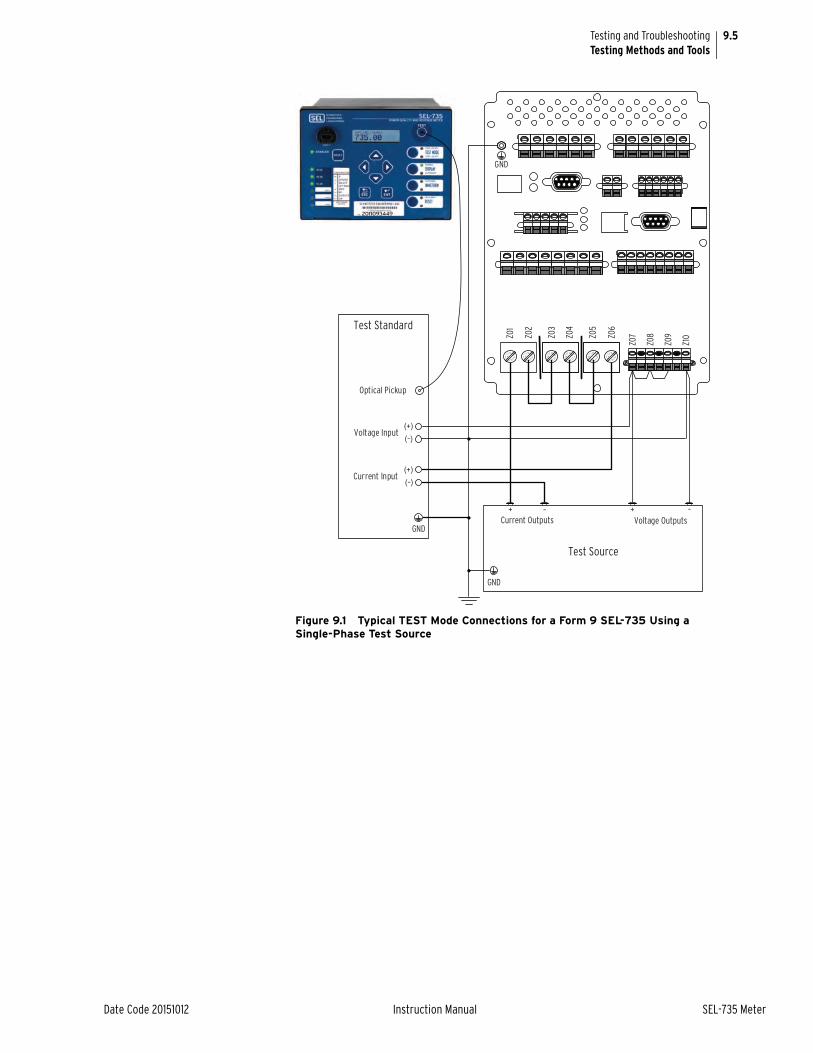
9.5
Date Code 20151012 Instruction Manual SEL-735 Meter
Testing and TroubleshootingTesting Methods and Tools
Figure 9.1 Typical TEST Mode Connections for a Form 9 SEL-735 Using a Single-Phase Test Source
+ –
Test Standard
+ –Current Outputs Voltage Outputs
Test Source
Voltage Input(+)(–)
(+)(–)
Current Input
Optical Pickup
Z01
Z02
Z03
Z04
Z05
Z06
Z10
GND
Z09
Z08
Z07
GND
GND

9.6
SEL-735 Meter Instruction Manual Date Code 20151012
Testing and TroubleshootingTesting Methods and Tools
Figure 9.2 Typical TEST Mode Connections for a Form 36 SEL-735 Using a Single-Phase Test Source
+ –
Test Standard
+ –Current Outputs Voltage Outputs
Test Source
Voltage Input(+)(–)
(+)(–)
Current Input
Optical Pickup
Z01
Z02
Z03
Z04
Z05
Z06
Z10
GND
Z09
Z08
Z07
GND
GND

9.7
Date Code 20151012 Instruction Manual SEL-735 Meter
Testing and TroubleshootingTesting Methods and Tools
Figure 9.3 Typical TEST Mode Connections for a Form 9 SEL-735 Using a Three-Phase Test Source
TEST Mode Options After the meter is in TEST mode you can change the following TEST mode options.
➤ Reset the test
You can reset the test at any time to perform the following actions:
➢ Test energy accumulation resets to zero
➢ Front-panel time-out resets
Please see Reset the Present Test on page 9.11 for more details.
➤ Test Mode Quantity
The active Test Mode Quantity displays on the LCD during TEST Mode. A change to this quantity resets the test but does not cause the meter to exit TEST Mode.
+
Test Standard
+
Current Outputs
A B C
Voltage Outputs
Test Source
+– – + –
Voltage Input
VaVbVcVn
Current Input
IA(+)IA(–)IB(+)IB(–)IC(+)IC(–)
Optical Pickup
Z01
Z02
Z03
Z04
Z05
Z06
Z10
GND
Z09
Z08
Z07
GND
GND+ + –

9.8
SEL-735 Meter Instruction Manual Date Code 20151012
Testing and TroubleshootingTesting Methods and Tools
➤ Watthour Constant
The watt-hour constant KET setting determines the amount of energy each KYZ pulse represents. Enter this value in secondary units. A change to this quantity resets the test but does not cause the meter to exit TEST mode.
➤ Compensation Settings
You can turn transformer line loss compensation (TLLC) on or off while in TEST Mode. The meter uses the TLLC settings you configured previously in performing compensation calculations. The meter restores the original TLLC settings when you exit TEST mode. Please see the Transformer/Line Loss Compensation on page 5.45 for more details. A change to this quantity resets the test but does not cause the meter to exit TEST mode.
➤ Gain Settings (not available in the ACSELERATOR QuickSet HMI)
You can adjust the watt and VAR Gain settings while in TEST mode. The meter saves the new watt and VAR gain settings permanently, even after the meter exits TEST Mode. A change to this quantity resets the test but does not cause the meter to exit TEST Mode.
Table 9.3 summarizes the TEST Mode options available during TEST Mode.
TEST Mode Operations
This section explains how to control the various TEST mode options.
Enter TEST ModeUse the control pushbuttons, ACSELERATOR QuickSet HMI, the front-panel pushbuttons, or a terminal prompt to enter TEST Mode. Use one of the following three communications methods to enter TEST Mode.
Control Pushbuttons1. If the default pushbutton controls are set (PBDFLT = Y), then
press the TEST Mode control pushbutton PB01 shown in Figure 9.4.
2. If prompted, enter a valid 2AC level password.
Table 9.3 TEST Mode Options
TEST Mode Option Option Description
Select Test Quantity Select the energy analog quantity you want to test
Watthour Constant Adjust the pulse constant
Compensation Setting Toggle transformer and line loss compensation on or off
Gain Settings Adjust watt and VAR gain

9.9
Date Code 20151012 Instruction Manual SEL-735 Meter
Testing and TroubleshootingTesting Methods and Tools
Figure 9.4 TEST Mode Control Pushbutton
If the default pushbutton controls are set then the TEST LED OFF illuminates when the meter first enters TEST mode. The TEST LED ON and TEST LED OFF indications alternate states as the TEST pulse turns on and off.
ACSELERATOR QuickSet HMI1. Open the ACSELERATOR QuickSet HMI and ensure successful
communications to the device.
2. Navigate to the Test Mode window.
3. Select the Test Mode Quantity you want to test.
4. Depending on your preference, either check or uncheck the Use Transformer Line Loss Compensation box.
5. Depending on your preference, either check or uncheck the Override KET box.
If you check this, then enter in the HMI the KET value you want. The device uses the KET value you entered from the HMI and enters TEST Mode. The meter does not save the KET value the next time you enter TEST Mode.
6. Click the Enter Test Mode button.
Figure 9.5 TEST Mode HMI
Figure 9.6 shows the HMI display from the Test Mode window. The HMI displays a representation of the front-panel optical port, which illuminates the left-hand infrared LED for the TEST pulse.
Press to Enter TEST Mode
Click to Enter TEST Mode

9.10
SEL-735 Meter Instruction Manual Date Code 20151012
Testing and TroubleshootingTesting Methods and Tools
Figure 9.6 ACSELERATOR QuickSet HMI TEST Mode Display
Front-Panel Menu Buttons1. Press the ENT button.
2. Activate the TEST Mode option.
3. Press the ENT button.
4. If prompted, enter a valid 2AC password.
If the front-panel control pushbuttons are set to default values, then the TEST LED OFF illuminates. The TEST LED ON and TEST LED OFF indications will alternate states as the TEST pulse turns on and off.
Terminal PromptYou can access and control TEST Mode on any rear-panel serial port via a terminal prompt (i.e., HyperTerminal®) that uses ASCII commands to communicate with the meter.
Perform the following steps blow to enter Test Mode via a terminal prompt.
1. Open a terminal prompt and connect to any rear-panel serial port.
2. Log on to the 2AC access level.
3. Enter the TEST MODE command according to the following syntax:
=>>TEST MODE<name>[TLLC]
where:
<name> is any valid Test Mode Quantity from Table 9.2.
If you include [TLLC] then the meter uses transformer/line loss compensation while in TEST mode.
Exit TEST ModeUse the ACSELERATOR QuickSet HMI, the Esc key, or a terminal prompt to exit TEST Mode. The meter restores all normal metering functions when it exits TEST Mode. Use one of the following three communications methods to exit TEST Mode.
ACSELERATOR HMIClick the Exit TEST Mode button.
TEST Pulse State
NOTE: You must first exit any serial port TEST Mode session in progress before you can access the SEL-735 front panel.
NOTE: This option is only available if you entered TEST mode via the ACSELERATOR QuickSet HMI.

9.11
Date Code 20151012 Instruction Manual SEL-735 Meter
Testing and TroubleshootingTesting Methods and Tools
Front-Panel Menu ButtonsPress the ESC button twice.
Terminal PromptEnter the TEST MODE OFF command at the terminal prompt.
In addition to the above options for exiting TEST Mode, the meter automatically exits TEST Mode if any of the following occur:
➤ The front-panel time-out expires.
➤ The meter loses power.
➤ The communications port you use to enter TEST Mode settings changes.
➤ The communications port you use to enter TEST Mode times out.
Reset the Present TestYou can reset the test at any time, which resets the present test energy. Use this feature to synchronize the timing of the meter and standard. For example, press and release RESET and start the standard at approximately the same time. Use one of the following three communications methods to reset the present test.
ACSELERATOR QuickSet HMIClick the Restart TEST Mode button.
Front-Panel Menu ButtonsPress the RESET button.
Terminal PromptEnter the TEST MODE command from the communications port on which you entered TEST Mode as Enter TEST Mode on page 9.8 explains.
Device Word Bits You can view the state of each Device Word bit to facilitate meter testing. Device Word bit information is available through the front panel, a terminal prompt, and the ACSELERATOR QuickSet HMI. Please apply the following guidelines to use Device Word bits in your testing.
Via Front PanelDisplay the state of Device Word bits by using the front-panel LCD Targets. Use the following steps to access the front-panel targets.
1. Press ENT.
2. Highlight Targets and press ENT.
The LCD displays the Device Word bits status by row number. See Appendix G: Analog Quantities and Device Word Bits for a list of Device Word bits.
NOTE: This option is only available if you entered TEST Mode via the ACSELERATOR QuickSet HMI.
NOTE: This option is only available if you entered TEST mode via the ACSELERATOR QuickSet HMI.

9.12
SEL-735 Meter Instruction Manual Date Code 20151012
Testing and TroubleshootingTesting Methods and Tools
Via Terminal PromptDisplay the state of all Device Word bits via a terminal prompt command. The command shows the state of one row of Device Word bits. Use the following steps to view the Device Word bit states.
Step 1. Open a terminal window and establish an SEL protocol connection to the meter.
Step 2. Log on to the ACC access level or higher.
Step 3. Enter the command TAR [name].
Where [name] is the Device Word bit name. If you omit the name, the meter displays Device Word bit row number zero. See Appendix G: Analog Quantities and Device Word Bits for a list of Device Word names bits and their row numbers.
As an example, to view the KYZD1 Device Word bit, issue the TAR KYZD1 command. The meter displays the state of all Device Word bits in the same row as KYZD1.
Via ACSELERATOR QuickSet HMIThe ACSELERATOR QuickSet HMI continuously polls the meter for the most recent Device Word bit states. Perform the following steps to view Device Word bits from the ACSELERATOR QuickSet HMI.
Step 1. Connect the ACSELERATOR QuickSet HMI to the meter.
Step 2. Click on Targets.
Step 3. View the desired Device Word bit state.
Output Contacts You can use the meter solid-state output contacts for meter testing. You must use solid-state contacts for meter testing to ensure fulfillment of the required timing and accuracy requirements.
Figure 9.7 shows the solid-state outputs contacts OUT401–OUT404, each with configured for different applications. See below for explanations of the different applications.
Figure 9.7 Solid-State Output Contact KYZ Options
Form A Test Pulse OutputFigure 9.7 shows OUT401 configured as a Form A test pulse output contact. With the meter in TEST Mode, the output contact pulses according to the state of the KYZDT Device Word bit.
NOTE: You can also enter the command as TAR [row number], where [row number] is the Device Word bit row number.

9.13
Date Code 20151012 Instruction Manual SEL-735 Meter
Testing and TroubleshootingTesting Methods and Tools
Form A Test Pulse or KYZ Pulse OutputFigure 9.7 shows OUT402 configured as a Form A test pulse or KYZ pulse output contact. With the meter in TEST Mode, the output contact pulses according to the state of the KYZDT Device Word bit. With the meter not in TEST mode, the output contact pulses according to the state of the KYZD1 Device Word bit.
Form A KYZ Pulse Output and Form C KYZ Pulse OutputFigure 9.7 shows OUT403 configured as a Form A KYZ pulse output contact. With the meter in TEST Mode, the output contact pulses according to the state of the KYZD1 Device Word bit.
Figure 9.7 shows OUT404 configured as a Form A KYZ pulse output contact in the state opposite to that of OUT403. Use OUT403 and OUT404 together to create a Form C pulse output contact. With the meter not in TEST mode, OUT403 and OUT404 pulse according to the state of the KYZD1 Device Word bit, but the state of OUT403 is always opposite to the state of OUT404.
Sequential Events Recorder
You can set the meter to generate an entry in the SER for testing meter elements. You can then compare the time stamps of the SER elements to other meter elements to verify timing between elements. See Section 6: Logging for more details on the SER.
For example, to test the first KYZ element, make the following setting.
SER1 = KYZD1
The Device Word bit KYZD1 pulses when there is load on the meter (assuming you have setup KYZD1). The meter adds an SER record each time KYZD1 asserts and deasserts.
Main Board Jumpers The main CPU board located in Slot B of the meter contains jumpers that affect the meter passwords, the output contact operation, and the SELBOOT mode.
Figure 9.8 shows a graphic of the jumpers located on the CPU board:
Figure 9.8 Jumper Header—Password and Breaker Jumpers
NOTE: If you use this configuration for calibration testing, you can only configure the test pulse with one other KYZ pulse. For example, the setting OUT402 := KYZT OR KYZD1 OR KYZD2 is invalid for calibration testing.
ON BKR
OFF PWD
SBT

9.14
SEL-735 Meter Instruction Manual Date Code 20151012
Testing and TroubleshootingGain Adjustment
Table 9.4 lists each of the jumpers and the default position of each.
Breaker Jumper, BKR (installed by default)This jumper is installed by default. The jumper enables or disables all of the output contacts. Install the jumper to enable the output contacts and remove the jumper to disable all of the output contacts.
Password Jumper, PWD (not installed by default)If you wish to disable password protection for all access levels, you can install the PWD jumper. When the jumper is installed, the meter grants users access to all access levels (ACC, EAC, 2AC, and CAL) without having to enter a password.
SELBOOT Jumper, SBT (not installed by default)This jumper forces the meter into SELBOOT mode. SELBOOT mode is used mainly for troubleshooting and when loading new firmware to the device; it should not be required for normal operations. When the meter is in SELBOOT, all metering functions stop operating. From SELBOOT, you may erase and send firmware, change the baud rate of the port, display the Firmware Identifier version and the SELBOOT version. Please see the Command Summary on page 8.14 for a list of commands available from SELBOOT.
Gain AdjustmentTo ensure that the SEL-735 meets ANSI Accuracy Class 0.2, SEL precisely calibrates each meter before it ships. A calibration report accompanying each meter details the measured error throughout a variety of operating conditions. Some customers require the ability to adjust or compensate for any error their test standard measures. The SEL-735 supports this requirement through the gain adjustment feature that scales power and energy values.
Use the WGAIN and VARGAIN settings to adjust watts and VARs. Through these adjustments, you can compensate for any measured error during an accuracy test. Equation 9.1 shows the calculation the SEL-735 performs with the gain adjustment settings.
Equation 9.1
Table 9.4 Main Board Jumpers
Jumper Default Jumper Position Function
N/A OFF N/A
N/A OFF N/A
BKR ON Breaker jumper
PWD OFF Password override
SBT OFF SELBOOT
where:X = either watts or VARs
Adjustment = the WGAIN or VARGAIN setting value
XAdjusted XMeasured 1Adjustment
100-------------------------------+
• =
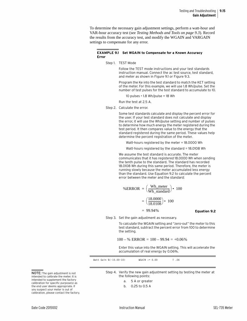
9.15
Date Code 20151012 Instruction Manual SEL-735 Meter
Testing and TroubleshootingGain Adjustment
To determine the necessary gain adjustment settings, perform a watt-hour and VAR-hour accuracy test (see Testing Methods and Tools on page 9.3). Record the results from the accuracy test, and modify the WGAIN and VARGAIN settings to compensate for any error.
EXAMPLE 9.1 Set WGAIN to Compensate for a Known Accuracy Error
Step 1. TEST Mode
Follow the TEST mode instructions and your test standards instruction manual. Connect the ac test source, test standard, and meter as shown in Figure 9.1 or Figure 9.3.
Program the Ke into the test standard to match the KET setting of the meter. For this example, we will use 1.8 Wh/pulse. Set the number of test pulses for the test standard to accumulate to 10.
10 pulses • 1.8 Wh/pulse = 18 Wh
Run the test at 2.5 A.
Step 2. Calculate the error.
Some test standards calculate and display the percent error for the user. If your test standard does not calculate and display the error, it will use the Wh/pulse setting and number of pulses to determine how much energy the meter registered during the test period. It then compares value to the energy that the standard registered during the same period. These values help determine the percent registration of the meter.
Watt-hours registered by the meter = 18.0000 Wh
Watt-hours registered by the standard = 18.0108 Wh
We assume the test standard is accurate. The meter communicates that it has registered 18.0000 Wh when sending the tenth pulse to the standard. The standard has recorded 18.0108 Wh during this same period. Therefore, the meter is running slowly because the meter accumulated less energy than the standard. Use Equation 9.2 to calculate the percent error between the meter and the standard:
Equation 9.2
Step 3. Set the gain adjustment as necessary.
To calculate the WGAIN setting and “zero-out” the meter to this test standard, subtract the percent error from 100 to determine the setting.
Enter this value into the WGAIN setting. This will accelerate the accumulation of real energy by 0.06%.
Watt Gain %(–10.00–10) WGAIN := 0.00 ? .06
Step 4. Verify the new gain adjustment setting by testing the meter at the following points:
a. 5 A or greater
b. 0.25 to 0.5 A
%ERRORWh_meter
Wh_standard-------------------------------- 100• =
18.000018.0108------------------- 100• =
99.94% =
100 % ERROR 100 99.94– +0.06% = =–
NOTE: The gain adjustment is not intended to calibrate the meter. It is intended to supplement the factory calibration for specific purpose(s) as the end user deems appropriate. If you suspect your meter is out of calibration, please contact the factory.

9.16
SEL-735 Meter Instruction Manual Date Code 20151012
Testing and TroubleshootingMeter Self-Tests
The readings at these points should be consistent with the gain values settings. For example, if you perform the test at 2.5 A, resulting in a +0.06% error, test at 0.5 A and 5.0 A to verify consistency of the watt-hour error at these points.
Determination of the VARGAIN setting is by the same method as the WGAIN setting.
The end user takes responsibility for applying these settings for appropriate reasons. Users should verify that any changes to WGAIN and VARGAIN return results they would expect under actual metering conditions.
Meter Self-TestsThe meter runs a variety of self-tests and reports the following notices for out-of-tolerance conditions (see Table 9.5):
➤ HALARM Assertion: The meter asserts the HALARM bit, which you can map to an output contact. Alarm condition signaling can be a single five-second pulse (Pulsed) or permanent (Latched).
➤ Automatic status reports at the ACSELERATOR QuickSet HMI.
➤ Failure messages on the meter LCD display for failures.
Use the ACSELERATOR QuickSet HMI Status window or front-panel STATUS menu to view meter self-test status.
Table 9.5 Meter Self-Tests (Sheet 1 of 2)
Self-Test Condition LimitsMeter
DisabledAlarm Output
Description
IA, IB, IC, IN, VA, VB, VC Offset
Warning ±50 mV No Pulsed Measures the dc offset at each of the input channels every 10 seconds
–5 V PS Failure –3.5 V
–6.5 V
Yes Latched –5 V power supply
+0.9 V PS Failure +1.01 V
+0.79 V
Yes Latched +0.9 V power supply
+1.2 V PS Failure +1.32 V
+1.08 V
Yes Latched +1.2 V power supply
+1.5 V PS Failure +1.65 V
+1.35 V
Yes Latched +1.5 V power supply
+1.8 V PS Failure +1.98 V
+1.62 V
Yes Latched +1.8 V power supply
+2.5 V PS Failure +2.75 V
+2.25 V
Yes Latched +2.5 V power supply
+3.3 V PS Failure +3.63 V
+2.97 V
Yes Latched +3.3 V power supply
+5 V PS Failure +5.75 V +4.25 V
Yes Latched +5 V power supply
BATT Warning +2.3 V No Pulse Measures the clock battery voltage
TEMP None –40°C+85°C
No Main board temperature for display only. No warnings or alarms are associated.
External RAM Failure — Yes Latched Read/write test on external RAM

9.17
Date Code 20151012 Instruction Manual SEL-735 Meter
Testing and TroubleshootingMeter Troubleshooting
Meter TroubleshootingInspection Procedure Complete the following procedure before disturbing the meter. After you
finish the inspection, proceed to Troubleshooting.
Step 1. Measure and record the power supply voltage at the power input terminals.
Step 2. Check to see that the power is on. Do not turn the meter off.
Step 3. Measure and record the voltage at all control inputs.
Step 4. Measure and record the state of all outputs.
TroubleshootingAll Front-Panel LEDs Dark
The following conditions cause the meter front-panel LEDs to turn off.
➤ Input power not present or power supply fuse is blown.
➤ Self-test failure asserted.
➤ Meter is in SELBOOT.
Cannot See Characters on LCDThe following conditions cause LCD characters to not display.
➤ Meter is de-energized. Check to see if the HALARM contact is closed.
➤ LCD contrast is out of adjustment. Use the steps below to adjust the contrast.
a. Press the ESC pushbutton for 5 seconds.
b. The meter should turn on LCD contrast display bar.
Critical RAM SELOGIC® Executable
Failure Checksum Yes Latched Read/write test on SELOGIC executable RAM
Critical RAM Setting Failure Checksum Yes Latched Read/write test on settings RAM
Critical RAM Code Failure Checksum Yesa Latched Read/write test on code RAM
ROM Failure Checksum Yes Latched Checksum test on the meter program
NONVOL Failure Checksum Yes Latched Checksum test on the nonvolatile memory
Dedicated circuitry in the microprocessor and the SEL-735 main board perform the following self-tests. Failures in these tests shut down the microprocessor and do not appear in the status report.
Microprocessor Failure Yes Latched The microprocessor examines each program instruction, memory access, and interrupt. The meter displays VECTOR nn on the LCD upon detection of an invalid instruction, memory access, or spurious interrupt. The test runs continuously.
a The meter stores program RAM failures into nonvolatile memory. A fourth program RAM failure occurring in the last 24 hours disables the device. If the device cycles power or resets, then the device erases the RAM failures recorded in nonvolatile memory.
Table 9.5 Meter Self-Tests (Sheet 2 of 2)
Self-Test Condition LimitsMeter
DisabledAlarm Output
Description

9.18
SEL-735 Meter Instruction Manual Date Code 20151012
Testing and TroubleshootingFactory Assistance
c. Use the LEFT ARROW and RIGHT ARROW pushbuttons to adjust the contrast.
d. Press the ESC pushbutton twice to return to normal operation.
Meter Does Not Respond to Serial CommandsThe following conditions cause serial communications to stop.
➤ Communications device not connected to meter.
➤ Meter or communications device at incorrect baud rate or other communications parameter incompatibility, including cabling error.
➤ Meter serial port has received an XOFF, halting communications. Type <Ctrl+Q> to send meter an XON and restart communications.
Information Lost During Power Cycle
The meter stores some data in volatile memory instead of nonvolatile memory. Loss of meter power erases volatile memory, causing certain meter elements to change. The following actions occur when meter power turns on and off.
➤ SELOGIC values, including timers and math variables, are lost. All values reset to zero when power returns.
➤ Remote bits deassert. Remote bits return to the OFF position when power returns.
➤ Contact outputs default to their nonenergized state. Outputs return to their energized state upon restoration of power.
➤ The meter loses as much as one minute of energy register data.
➤ The present peak-demand data value restart at zero.
Factory AssistanceWe appreciate your interest in SEL products and services. If you have questions or comments, please contact us at:
Schweitzer Engineering Laboratories, Inc.2350 NE Hopkins CourtPullman, WA 99163-5603 U.S.A. Tel: +1.509.332.1890 Fax: +1.509.332.7990 Internet: www.selinc.comE-mail: [email protected]

Date Code 20151012 Instruction Manual SEL-735 Meter
Appendix AFirmware and Manual Versions
FirmwareDetermining the Firmware Version in Your Meter
To determine the firmware version, view the status report in your SEL-735 using the serial port STAT command or the front-panel STATUS pushbutton. The status report displays the Firmware Identification (FID) label.
The firmware version will be either a standard release or a point release. A standard release adds new functionality to the firmware beyond the specifications of the existing version. A point release is reserved for modifying firmware functionality to conform to the specifications of the existing version.
A standard release is identified by a change in the R-number of the device firmware identification (FID) string.
Existing firmware:
FID=SEL-735-R100-V0-Z001001-Dxxxxxxxx
Standard release firmware:
FID=SEL-735-R101-V0-Z001001-Dxxxxxxxx
A point release is identified by a change in the V-number of the device FID string.
Existing firmware:
FID=SEL-735-R100-V0-Z001001-Dxxxxxxxx
Point release firmware:
FID=SEL-735-R100-V1-Z001001-Dxxxxxxxx
The release date is after the D. For example, the following is firmware revision number 100, release date June 28, 2011.
FID=SEL-735-R100-V0-Z001001-D20110628
Table A.1 lists the firmware versions, a description of modifications, and the instruction manual date code that corresponds to firmware versions. The most recent firmware version is listed first.

A.2
SEL-735 Meter Instruction Manual Date Code 20151012
Firmware and Manual VersionsFirmware
Table A.1 Firmware Revision History (Sheet 1 of 4)
Firmware Identification (FID) Number Summary of RevisionsManual
Date Code
SEL-735-R115-V3-Z008005-D20151012 Includes all the functions of SEL-735-R115-V2-Z008005-D20150929 with the following addition:➤ Resolved an issue where the Time-of-Use feature will record all
energy and demand data only in the first programmed rate for each schedule. This issue existed on firmware version R113-V0 through R115-V2.
20151012
SEL-735-R115-V2-Z008005-D20150929 Includes all the functions of SEL-735-R115-V1-Z008005-D20150908 with the following addition:
➤ Modified firmware to resolve a settings exchange incompatibility between the SEL-735 and ACSELERATOR QuickSet®.
20150929
SEL-735-R115-V1-Z008005-D20150908 Includes all the functions of SEL-735-R115-V0-Z008005-D20150519 with the following addition:
➤ Resolved an issue where the Ethernet port could become unrespon-sive when a DNP/IP master on a TCP session polls for a large amount of data, then either disconnects or is disconnected by another DNP/IP master connecting to the same session.
20150908
SEL-735-R115-V0-Z008005-D20150519 ➤ Corrected an issue where the meter restarted or stopped operating during file transfers in the presence of a saturated network.
➤ Resolved an issue that caused the SEL-735 to place incorrect values into the energy preload settings and SELOGIC counter value settings during an FTP settings read.
20150519
SEL-735-R114-V0-Z008005-D20150403 ➤ Modified the order of the Digital Status Word bits in the IEEE C37.118.2 synchrophasor messages to match the order defined in the synchrophasor configuration frame.
20150403
SEL-735-R113-V0-Z008005-D20150324 ➤ Added P Class IEEE C37.118 synchrophasors and associated config-uration settings.
20150324
➤ Increased the maximum VBASE setting value in Form 5 meters from 300 VL-L to 480 VL-L.
➤ Resolved an issue where the KYZ contacts, when configured for net metering, only pulsed when the accumulated energy resulted in an increase to either the net delivered or net received value of the Net Energy registers.
➤ Added support for IRIG-B control bits as required by IEEE C37.118-2011.
➤ Removed Form 36, B-Phase voltage Instrumentation Transformer Compensation (ITC) settings.
➤ The End of Interval Pulse (EOIP) now asserts when a user or an external time source advances the meter clock across a demand inter-val boundary.
➤ Added a Time-Change Threshold (TIME_CHG) setting allowing users to adjust the threshold for time changes beyond which the meter flags affected data.
➤ Increased the DNP event buffer size from 10 messages per event type to 1024 messages per event type.
➤ Improved the typical time-keeping drift from 50 seconds per month to 5 seconds per month.
➤ Improved the time-keeping accuracy to comply with IEC 61000-4-30 Class A requirements.
➤ Enhanced harmonic, and interharmonic measurements to comply with IEC 61000-4-30 Class A.

A.3
Date Code 20151012 Instruction Manual SEL-735 Meter
Firmware and Manual VersionsFirmware
➤ Resolved an issue where the DNP Restart Bit asserted when a DNP client restored a TCP session; now the DNP Restart Bit only asserts when the SEL-735 restarts.
➤ DNP Frozen Counters now maintain their value when the DNP client disconnects and restores the DNP session.
SEL-735-R112-V0-Z006004-D20141223 ➤ Added an EIA-232 front-port option for vertical chassis meters. 20141223
SEL-735-R111-V0-Z006004-D20141107 ➤ In Firmware revisions R107 to R110, the current and power mea-surements fluctuate when the Enable ITC for Current (EITCI) setting is enabled and 0.5 A is applied to the CL2/20/20 meter or 2.5 A is applied to the CL10/20 meter. Now, current and power measure-ments do not fluctuate under those conditions.
➤ In Firmware revisions R107 to R110, Instrument Transformer Com-pensation settings were not applied to real power and real energy quantities when currents below 0.5 A were applied to the CL2/CL10/CL20 meter or currents below 2.5 A were applied to the CL10/CL20 meter. Firmware now applies Instrumentation Trans-former Compensation settings to rms quantities across the published current range.
20141107
SEL-735-R110-V0-Z006004-D20140507 ➤ Modified the starting current behavior and added the Starting Current Threshold (IST) and Starting Current Type (IST_TYPE) settings. Previously, the meter zeroed the current registration when the RMS current magnitude was less than a fixed threshold.
➤ Modified the fiber Ethernet link LED behavior to be consistent with copper Ethernet ports. Previously, the green link LED located next to the fiber Ethernet ports did not flash to indicate Rx/Tx activity. The LED remained on.
➤ Modified the port power behavior and added the Enable Port Power setting. Previously, EIA-232 ports always supplied +5 V power from Pin 1.
20140507
SEL-735-R109-V0-Z005004-D20131015 ➤ Manual update only (see Table A.2). 20140313
SEL-735-R109-V0-Z005004-D20131015 ➤ Corrected an issue where a serial port that was in an XOFF state would not time out.
20131015
➤ Increased the accuracy of energy data reported over DNP when configured to report more than two decimal places.
➤ Increased the accuracy of the energy and demand data stored in Load Profile Recorders (LDP) 2–12.
➤ Added functionality to ensure that the meter operates properly when users connect a serial cable that short circuits Pin 1 of the EIA-232 ports to ground.
➤ Added Form 36 (2-1/2 element) metrology.
➤ Corrected the Voltage Sag/Swell/Interruption (VSSI) initialization voltage threshold.
➤ Corrected a potential issue where issuing the MET A command might cause the meter communications port to stop responding to some commands.
➤ Corrected an issue that caused the KYZ pulses to use compensated energy quantities when uncompensated quantities were selected.
➤ Corrected an issue that caused the meter to reject some valid display point settings.
➤ Corrected an issue where the meter diagnostics reported OFFSET WARN on VA, VB, VC, and VN when the meter was starting up.
➤ Improved the ease of use of the TPORT setting on the meter HMI.
Table A.1 Firmware Revision History (Sheet 2 of 4)
Firmware Identification (FID) Number Summary of RevisionsManual
Date Code

A.4
SEL-735 Meter Instruction Manual Date Code 20151012
Firmware and Manual VersionsFirmware
➤ Corrected an issue that could cause the energy data stored in Load Profile Recorders (LDP) 2–12 to truncate the most significant digit when the recorder is set to Change Over Interval (COI).
➤ Corrected an issue where the last row of a Voltage Sag/Swell/Inter-ruption (VSSI) event was not written to nonvolatile memory in a timely manner. This last row did not affect the VSSI summary, since it contains data from after the VSSI event concludes.
SEL-735-R108-V0-Z004003-D20130906 ➤ Corrected an issue that prevented the meter from accepting FTP file writes. This only occurs after the user cancels an FTP read of the SET_ALL.TXT file.
20130906
SEL-735-R107-V0-Z004003-D20130701
Note: Firmware revision R106 did not production release.
➤ Added gratuitous Address Resolution Protocol (ARP) messages to network communications.
➤ Corrected a DNP LAN/WAN issue which caused the meter to trans-mit values of zero in response to a single poll from the DNP server.
➤ Added IEC 61850 protocol with MMS Reporting and GOOSE.
➤ Added File Transfer Protocol (FTP).
➤ Added TCP Keep-Alive settings.
➤ Added Simple Network Time Protocol (SNTP).
20130701
➤ Added Instrument Transformer Compensation (ITC).
➤ Added active and reactive uncompensated analog quantities.
➤ Corrected an issue where the meter reported zero fundamental-only reactive power when the power angle was less than 1 degree.
➤ Corrected the dynamic base voltage feature where the meter reported incorrect Voltage Sag/Swell/Interruption data.
➤ Changed the factory-default display point formatting.
➤ Corrected an issue where sending design templates to the device at 9600 baud would fail.
➤ Corrected an issue where the meter disabled and reported NONVOL FAIL because of temporary nonvolatile memory issues.
➤ Added virtual bits VB001–VB128.
➤ Corrected an issue where the SER Power Loss entries were not in chronological order with other SER entries.
➤ Corrected an issue where upgrading from firmware version R100 or R104 could cause the user-defined Configurable Registers to report zero on all external interfaces.
➤ Corrected an issue that could be encountered while sending a file via YMODEM.
SEL-735-R105-V0-Z003002-D20130228 ➤ Manual update only (see Table A.2). 20130515
SEL-735-R105-V0-Z003002-D20130228 ➤ Corrected issues with time-of-use and Daylight Saving Time functions.
➤ Added fundamental-only power values updated every 1/2 cycle.
➤ Added support for single-mode fiber-optic port.
20130228
SEL-735-R104-V0-Z002002-D20121005 ➤ Corrected behavior of KYZ settings with respect to forcing output contact settings.
20121005
SEL-735-R103-V0-Z002002-D20120608 ➤ The length of unfiltered event reports is now two cycles more than the LER setting.
20120608
➤ The maximum prefault duration in unfiltered event reports is now two cycles more than the PRE setting.
➤ Improved VSSI logic to detect immediate transitions between Interrupts and Swells.
➤ Corrected power calculations for Form 5 single-phase testing.
➤ Corrected filtered event report scaling for Form 5 meters.
Table A.1 Firmware Revision History (Sheet 3 of 4)
Firmware Identification (FID) Number Summary of RevisionsManual
Date Code

A.5
Date Code 20151012 Instruction Manual SEL-735 Meter
Firmware and Manual VersionsInstruction Manual
Instruction ManualThe date code at the bottom of each page of this manual reflects the creation or revision date.
Table A.2 lists the instruction manual release dates and a description of modifications. The most recent instruction manual version is listed first.
➤ Corrected SELOGIC Variable Timer accuracy.
➤ Modified COMTRADE CFG files to represent variable sampling rate.
SEL-735-R102-V0-Z002002-D20111111 ➤ Manual update only (see Table A.2). 20120319
SEL-735-R102-V0-Z002002-D20111111 ➤ Changed three-phase energy calculation. Addresses three-phase energy accumulation when power flows in opposite directions on different phases.
20111111
SEL-735-R101-V0-Z002002-D20110818 ➤ Added option for front-panel EIA-232 serial port.
➤ Added option for 100 A fault recording.
20110818
SEL-735-R100-V0-Z001001-D20110628 ➤ Initial version. 20110628
Table A.1 Firmware Revision History (Sheet 4 of 4)
Firmware Identification (FID) Number Summary of RevisionsManual
Date Code
Table A.2 Instruction Manual Revision History (Sheet 1 of 5)
Revision Date Summary of Revisions
20151012 Appendix A
➤ Updated for firmware version R115-V3.
20150929 Appendix A
➤ Updated for firmware version R115-V2.
20150908 Appendix A
➤ Updated for firmware version R115-V1.
20150519 Section 1
➤ Updated Table 1.2: SEL-735 Compliance With IEC 61000-4-30 Power Quality Standard.
➤ Added Table 1.3: SEL-735 Waveform Capture Settings Options for Event Reports.
Appendix A
➤ Updated for firmware version R115.
20150403 Appendix A
➤ Updated for firmware version R114.
20150324 Section 1
➤ Updated Table 1.2: SEL-735 Feature Availability.
➤ Updated Specifications.
Section 2
➤ Updated Configure and Check Meter Status to include note about Analog Quantity Scaling.
Section 3
➤ Updated the overview of Access Level EAC.
Section 4
➤ Updated Aggregated Registers to Aggregated Values.
➤ Added Synchrophasors.

A.6
SEL-735 Meter Instruction Manual Date Code 20151012
Firmware and Manual VersionsInstruction Manual
Settings Sheets
➤ Updated Instrument Transformer Compensation.
➤ Updated Global Settings.
➤ Added Synchrophasor Settings.
➤ Updated Voltage Sag/Swell/Interruption Settings.
➤ Updated Ports.
➤ Moved DNP Ethernet Session Settings.
➤ Added PMU Session Settings.
Section 5
➤ Updated IEC 61000-4-30 Testing and Measurement Techniques—Power Quality Measurement Methods.
➤ Updated Measurement Aggregation.
➤ Added Time Sources and The Effects of Time Changes under the heading, Voltage, Current, and Power Calcu-lations.
Section 8
➤ Updated Port Connector and Communications Cables.
➤ Added Synchrophasors and SNTP to Communications Protocols.
➤ Removed Table 8.11: Command Summary and made it a separate section.
Appendix A
➤ Updated for firmware version R113.
Appendix D
➤ Updated Overview and Table D.5 DNP3 Device Profile.
Appendix E
➤ Updated Table E.24 Modbus Enumeration Definitions.
Appendix G
➤ Updated Overview.
➤ Updated Table G.5: Frequency, Table G.10: Advanced: Diagnostics, Table G.25: SEL-735 Device Word Bit Definitions, and Table G.25: SEL-735 Device Word Bit Definitions.
Appendix H
➤ Updated GOOSE Performance.
Glossary
➤ Added RTC.
Command Summary
➤ Updated Command Summary.
20141223 Preface
➤ Updated Safety Information.
Section 1
➤ Updated Table 1.2: SEL-735 Feature Availability.
➤ Updated Specifications.
Section 2
➤ Updated to include EIA-232 front-port option for vertical chassis meters.
➤ Updated Figure 2.11: SEL-735 Model Option Table.
Section 4
➤ Updated Settings.
Settings
➤ Updated Voltage Sag/Swell/Interruption Settings.
➤ Updated Communications Settings.
Section 5
➤ Updated Flicker Metering.
➤ Updated Table 5.18: Configurable Register Attributes.
Table A.2 Instruction Manual Revision History (Sheet 2 of 5)
Revision Date Summary of Revisions

A.7
Date Code 20151012 Instruction Manual SEL-735 Meter
Firmware and Manual VersionsInstruction Manual
Section 7
➤ Updated Table 7.12: SELOGIC Control Equation Counter Inputs.
Appendix A
➤ Updated for firmware revision R112.
Appendix H
➤ Updated IEC 61850 Operation.
20141107 Appendix A
➤ Updated for firmware version R111.
20140507 Section 1
➤ Updated SEL-735 Meter Forms and Models section.
➤ Updated Specifications section.
Section 3
➤ Added explanation of number of characters per line displayed by the LCD.
Settings Sheets
➤ Added settings IST and IST_TYPE to Advanced Global Settings.
➤ Added setting EPP to Communications Settings.
Section 5
➤ Added command syntax of FORM command in Form Factor Support.
➤ Added Starting Current section.
Section 8
➤ Changed description of green LED in Table 8.6: Ethernet Port LED Description.
Appendix A
➤ Updated for firmware version R110.
Command Summary
➤ Added MET D, MET D P, MET D P U, MET D T, MET D T U, and MET D U commands.
20140313 Section 1
➤ Updated Specifications section.
20131015 Section 1
➤ Updated for Form 36 Metering.Section 5
➤ Added Form 36 Metering.Appendix A
➤ Updated for firmware version R109.
20130906 Appendix A
➤ Updated for firmware version R108.
20130701 Section 5
➤ Added Instrument Transformer Compensation.
➤ Updated Transformer/Line Loss Compensation.
Section 8
➤ Added FTP and MMS.
➤ Added Command Explanations.
Appendix A
➤ Updated for firmware version R107.
Appendix G
➤ Added new uncompensated analog quantities.
Appendix H
➤ Added Appendix H: IEC 61850 Communications.
Table A.2 Instruction Manual Revision History (Sheet 3 of 5)
Revision Date Summary of Revisions

A.8
SEL-735 Meter Instruction Manual Date Code 20151012
Firmware and Manual VersionsInstruction Manual
20130515 Section 1
➤ Updated Specifications for single-mode fiber-optic support.
Section 5
➤ Corrected transformer line-loss compensation equations.
Section 8
➤ Updated Table 8.1: Meter Models and Available Main Board Communications Options for single-mode fiber-optic support.
20130228 Section 5
➤ Corrected Demand Metering explanation.
Section 8
➤ Corrected SEL-735 Command Summary.
Appendix A
➤ Updated for firmware version R105.
Appendix G
➤ Revised Table G.1: Analog Quantities Available to Internal Interface Types and analog quantities.
20121005 Section 1
➤ Updated Output Contacts Pickup/Dropout Time in Specifications.
Section 5
➤ Added Neutral Current.
Appendix A
➤ Updated for firmware version R104.
20120608 Appendix A
➤ Updated for firmware version R103.
20120319 Section 1
➤ Updated Table 1.2: SEL-735 Feature Availability.
➤ Updated Figure 1.2: SEL-735 Inputs, Outputs, and Communications Ports.
➤ Added Fiber-Optic Ethernet Port in Specifications.
Section 2
➤ Updated Figure 2.6: Four-Wire Wye and Three-Wire Delta Wiring Diagrams.
➤ Updated Table 2.4: Default SEL-735 Settings and Required acSELerator QuickSet Communications Parameters.
Section 3
➤ Use of Configurable Registers in Display Points added in Display Points.
Settings
➤ Added Table SET.2 and introductory text in Communications Settings.
Section 5
➤ Updated thermal demand algorithm in Comparison of Thermal, Rolling, and Block Demand Meters.
➤ Updated Figure 5.28: FAULT and DFAULT Device Word Bit Logic.
➤ Changed amount for maximum positive-sequence current in Fault Detection.
➤ Removed basic underpower quality and recording option in Table 5.14: Flicker Quantities Available.
➤ Updated Table 5.17: Configurable Register Attributes.
➤ Updated Table 5.18: Configurable Register Spreadsheet Example.
➤ Updated Figure 5.33: Meter and Billing Positions and Table 5.15: Transformer and Line Loss Adjustments.
Section 7
➤ Removed reference to logic updates in processing cycle in Output Contacts.
➤ Updated Example and Figure 7.3: Analog Output Settings Example in DC Analog Output.
Table A.2 Instruction Manual Revision History (Sheet 4 of 5)
Revision Date Summary of Revisions

A.9
Date Code 20151012 Instruction Manual SEL-735 Meter
Firmware and Manual VersionsInstruction Manual
Section 8
➤ Updated Ethernet section in Port Connector and Communications Cables.
➤ Updated Table 8.7: Port Pinout Functions.
➤ Updated Table 8.10: Command Summary.
Appendix D
➤ Updated VSSI Summary Records.
➤ Removed Event Summary Records.
Appendix G
➤ Updated Table G.1: Analog Quantities Available to Internal Interface Types.Command Summary
➤ Updated with additional commands.
20111216 Appendix A
➤ Updated for firmware version R102.
20111111 Section 1
➤ Updated Waveform Capture duration values in Table 1.2: SEL-735 Feature Availability.
➤ Added Fiber-Optic Ethernet Port specifications to Specifications section.Appendix A
➤ Updated for firmware version R102.
20110818 Section 1
➤ Modified for 100 A fault recording addition.Appendix A
➤ Updated for firmware version R101.
20110628 ➤ Initial version.
Table A.2 Instruction Manual Revision History (Sheet 5 of 5)
Revision Date Summary of Revisions

This page intentionally left blank

Date Code 20151012 Instruction Manual SEL-735 Meter
Appendix BSEL-735 Upgrade Instructions
Overview
These instructions describe how to install various SEL-735 upgrades including firmware, meter form changes, and intermediate/advanced power quality. The firmware upgrade will be either a standard release or a point release. A standard release adds new functionality to the firmware beyond the specifications of the existing version. A point release is reserved for modifying firmware functionality to conform to the specifications of the existing version.
A standard release is identified by a change in the R-number of the device firmware identification (FID) string.
Existing firmware:
FID=SEL-735-R100-V0-Z001001-Dxxxxxxxx
Standard release firmware:
FID=SEL-735-R101-V0-Z001001-Dxxxxxxxx
A point release is identified by a change in the V-number of the device FID string.
Existing firmware:
FID=SEL-735-R100-V0-Z001001-Dxxxxxxxx
Point release firmware:
FID=SEL-735-R100-V1-Z001001-Dxxxxxxxx
The release date is after the D. For example, the following is firmware revision number 100, release date June 28, 2011.
FID=SEL-735-R100-V0-Z001001-D20110628
Equipment Needed Obtain the following equipment prior to performing this procedure:
➤ Personal Computer (PC) with serial port capable of 115.2 kbps (with Microsoft® Windows® 98, 2000, XP, or Vista®)
➤ Communications cable:
➢ 38.4 kbps compatible for Port F (C660 or C661)
➢ 115.2 kbps compatible for Port 2 or Port 3 (C234 or C287)
➤ SEL-735 Access Level 1 and Access Level 2 passwords

B.2
SEL-735 Meter Instruction Manual Date Code 20151012
SEL-735 Upgrade InstructionsInstallation
Installation
Step 1. Place the Meter Upgrade Software CD in the PC CD-ROM drive. The software should run automatically.
If the software fails to run automatically, use Windows Explorer to browse the CD-ROM contents, and run the Setup.exe file.
Step 2. The software will prompt for a shortcut location. Select one or both of the locations and click Install.
Step 3. Click Close to complete the installation and launch the software.
Clear the check box to run the software at a later time.
Upgrade Procedure
Step 1. Use an optical or serial cable to connect a PC to the SEL-735 Port 2, Port F, or EIA-232 Port 3. For faster upgrades, connect to the SEL-735 Port 2 or EIA-232 Port 3 instead of Port F.
Step 2. Double-click the Meter Upgrade Software shortcut saved on the desktop or from the Start menu to run the software.
Step 3. A PC Port dialog box displays on the PC screen. Select the PC port that is connected to the SEL-735, and click OK to view a list of available upgrades.
Step 4. Select from the list of available upgrades and click Upgrade.
The software will automatically install the selected upgrades and prompt when completed.
Step 5. Click OK to acknowledge completion of the upgrade process and close the software.
IMPORTANT: SEL charges for intermediate/advanced power quality and password protects these options. If you purchased an intermediate/ advanced power quality, please refer to the Meter Upgrade Software Kit for the passwords. Please contact SEL if you would like to purchase an upgrade.

Date Code 20151012 Instruction Manual SEL-735 Meter
Appendix CSEL Communications Processors
SEL Communications ProtocolsThe SEL-735 supports the protocols and command sets shown in Table C.1.
SEL ASCII Commands The SEL ASCII protocol supports commands between the meter and a human operator via a keyboard and monitor or a printing terminal. A computer with a serial port can also use the SEL ASCII protocol to communicate with the meter, collect data, and issue commands.
SEL Compressed ASCII Commands
The meter supports a subset of SEL ASCII commands identified as Compressed ASCII commands. Each of these commands results in a comma-delimited message that includes a checksum field. Most spreadsheet and database programs can directly import comma-delimited files. Devices with embedded processors connected to the meter can execute software to parse and interpret comma-delimited messages without expending the customization and maintenance labor necessary to interpret nondelimited messages. The meter calculates a checksum for each line by numerically summing all of the bytes that precede the checksum field in the message. The program that uses the data can detect transmission errors in the message by summing the characters of the received message and comparing this sum to the received checksum.
Most commands are available only in SEL ASCII or Compressed ASCII format. Selected commands have versions in both standard SEL ASCII and Compressed ASCII formats. Compressed ASCII reports generally have fewer characters than conventional SEL ASCII reports, because the compressed reports reduce blanks, tabs, and other “white space” between data fields to a single comma.
Table C.1 Supported Serial Command Sets
Command Set Description
SEL ASCII Sends ASCII commands and receives ASCII responses that are human readable with an appropriate terminal emulation program.
SEL Compressed ASCII Sends ASCII commands and receives Compressed ASCII responses that are comma delimited for use with spreadsheet and database programs or for use by intelligent electronic devices.
SEL Fast Meter Sends binary commands and receives binary meter and target responses.
SEL Fast Operate Receives binary control commands.
SEL Fast SER Receives binary Sequential Events Recorder unsolicited responses.

C.2
SEL-735 Meter Instruction Manual Date Code 20151012
SEL Communications ProcessorsSEL Communications Protocols
Table C.2 lists the Compressed ASCII commands and contents of the responses.
Interleaved ASCII and Binary Messages
SEL meters have two separate data streams that share the same physical serial port. Human data communications with the meter consist of ASCII character commands and reports that you view by using a terminal or terminal emulation package. The binary data streams can interrupt the ASCII data stream to obtain information; the ASCII data stream continues after the interruption. This mechanism uses a single communications channel for ASCII communication (transmission of an event report, for example) interleaved with short bursts of binary data to support fast acquisition of metering data. The device connected to the other end of the link requires software that uses the separate data streams to exploit this feature. However, you do not need a device to interleave data streams to use the binary or ASCII commands. Note that XON, XOFF, and CAN operations operate on only the ASCII data stream.
An example of using these interleaved data streams is when the SEL-735 communicates with an SEL communications processor. These SEL communications processors perform auto-configuration by using a single data stream and SEL Compressed ASCII and binary messages. In subsequent operations, the SEL communications processor uses the binary data stream for Fast Meter, and Fast Operate messages to populate a local database and to perform SCADA operations. At the same time, you can use the binary data stream to connect transparently to the SEL-735 and use the ASCII data stream for commands and responses.
SEL Fast Meter, Fast Operate, and Fast SER Messages
SEL Fast Meter is a binary message that you solicit with binary commands. Fast Operate is a binary message for control. The meter can also send unsolicited Fast SER messages automatically. If the meter is connected to an SEL communications processor, these messages provide the mechanism that the communications processor uses for SCADA or DCS functions that occur simultaneously with ASCII interaction.
SEL Application Guide AG95-10, Configuration and Fast Meter Messages, is a comprehensive description of SEL binary messages.
Table C.2 Compressed ASCII Commands
Command Response Access Level
BNAME ASCII names of Fast Meter status bits 0
CASCII Configuration data of all Compressed ASCII commands available at access levels > 0
0
CEVENT Event report 1
CHISTORY List of events 1
DNAME ASCII names of digital I/O reported in Fast Meter 0
ID Meter identification 0
SNS ASCII names for SER data reported in Fast Meter 0

C.3
Date Code 20151012 Instruction Manual SEL-735 Meter
SEL Communications ProcessorsSEL Communications Processor
SEL Communications ProcessorSEL offers communications processors that are powerful tools for system integration and automation. These devices provide a single point of contact for integration networks with a star topology as shown in Figure C.1.
Figure C.1 SEL Communications Processor Star Integration Network
In the star topology network in Figure C.1 the SEL communications processor offers the following substation integration functions:
➤ Collection of real-time data from SEL and non-SEL IEDs
➤ Calculation, concentration, and aggregation of real-time IED data into databases for SCADA, HMI, and other data consumers
➤ Access to the IEDs for engineering functions including configuration, report data retrieval, and control through local serial, remote dial-in, and Ethernet network connections
➤ Simultaneous collection of SCADA data and engineering connection to SEL IEDs over a single cable
➤ Distribution of IRIG-B time-synchronization signal to IEDs based on external IRIG-B input, internal clock, or protocol interface
➤ Automated dial out on alarms
The SEL communications processors have as many as 33 serial ports plus a front port. This port configuration does not limit the size of a substation integration project, because you can create a multitiered solution as shown in Figure C.2. In this multitiered system, the lower-tier SEL communications processors forward data to the upper-tier SEL communications processor that serves as the central point of access to substation data and station IEDs.
SEL CommunicationsProcessor
To Engineering
Modem
To SCADA
Local HMI
SEL IED SEL IED SEL IED Non-SEL IED

C.4
SEL-735 Meter Instruction Manual Date Code 20151012
SEL Communications ProcessorsSEL Communications Processor
The SEL-735 supports the Fast Meter commands as listed in Table C.3.
Figure C.2 Multitiered SEL Communications Processor Architecture
You can add additional communications processors to provide redundancy and eliminate possible single points of failure. SEL communications processors provide an integration solution with a reliability comparable to that of SEL meters. In terms of mean time between failures (MTBF), SEL communications processors are 100 to 1000 times more reliable than computer-based and industrial technology-based solutions.
Configuration of an SEL communications processor differs from other general-purpose integration platforms. You can configure SEL communications processors with a system of communications-specific keywords and data movement commands rather than programming in C or another general-purpose computer language. SEL communications processors offer the protocol interfaces listed in Table C.4.
Table C.3 SEL-735 Fast Meter Commands
Command Description
A5C0 SEL-735 Fast Meter definition message
A5C1 Fast Meter configuration message
A5D1 Fast Meter data message
A5C2 Demand Fast Meter configuration message
A5D2 Demand Fast Meter data message
A5C3 Peak demand Fast Meter configuration message
A5D3 Peak demand Fast Meter data message
A5B9 Status bits clear command
SEL CommunicationsProcessor
To Engineering
ModemTo SCADA
Local HMI
SEL IED
SEL IED
SEL IED
Non-SEL IED
SEL IED
SEL IED
SEL IED
Non-SEL IED
SEL CommunicationsProcessor
SEL CommunicationsProcessor

C.5
Date Code 20151012 Instruction Manual SEL-735 Meter
SEL Communications ProcessorsSEL Communications Processor and Meter Architecture
SEL Communications Processor and Meter Architecture
You can apply SEL communications processors and SEL meters in a limitless variety of applications that integrate, automate, and improve station operation. Most system integration architectures using SEL communications processors involve either developing a star network or enhancing a multidrop network.
Developing Star Networks
Figure C.1 shows the simplest architecture that uses both the SEL-735 and an SEL communications processors. In this architecture, the SEL communications processor collects data from the SEL-735 and other station IEDs. The SEL communications processor acts as a single point of access for local and remote data consumers (local HMI, SCADA, engineers). The communications processor also provides a single point of access for engineering operations that includes configuration and the collection of report-based information.
By configuring a data set optimized to each data consumer, you can significantly increase the utilization efficiency on each link. A system that uses an SEL communications processor to provide a protocol interface to an RTU will have a shorter lag time (data latency); communications processor overhead is much less for a single data exchange conversation to collect all substation data than for many conversations necessary to collect data directly from each individual IED. You can further reduce data latency by connecting an SEL communications processor directly to the SCADA master and eliminating redundant communications processing in the RTU.
The SEL communications processor is responsible for the protocol interface, so you can install, test, and even upgrade the system in the future without disturbing protective meters and other station IEDs. This insulation of the
Table C.4 SEL Communications Processors Protocol Interfaces
Protocol Connect to
DNP3 Level 2 Slave DNP3 masters
Modbus® RTU Modbus masters
Modbus® TCP Modbus masters with Ethernet
SEL ASCII/Fast Message Slave SEL protocol masters
SEL ASCII/Fast Message Master SEL protocol slaves including other communica-tions processors and SEL meters
ASCII and Binary auto messaging SEL and non-SEL IED master and slave devices
Modbus Plusa
a Requires SEL-2711 Modbus Plus protocol card.
Modbus Plus peers with global data and Modbus Plus masters
FTP (File Transfer Protocol)b
b Requires SEL-2701 Ethernet Processor.
FTP clients
Telnetb Telnet servers and clients
UCA2 GOMSFEb UCA2 protocol masters
UCA2 GOOSEb UCA2 protocol and peers

C.6
SEL-735 Meter Instruction Manual Date Code 20151012
SEL Communications ProcessorsSEL Communications Processor and Meter Architecture
meters from the communications interface assists greatly in situations where different departments are responsible for SCADA operation, communication, protection, and metering.
The engineering connection can use either an Ethernet network connection or a serial port connection. This versatility accommodates the channel available between the station and the engineering center. SEL software, including ACSELERATOR QuickSet® SEL-5030 Software, can use either a serial port connection or an Ethernet network connection from an engineering workstation to the meters in the field.
Enhancing Multidrop Networks
You can also use an SEL communications processor to enhance a multidrop architecture similar to the one shown in Figure C.3. In this example, the SEL communications processor enhances a system with an Ethernet HMI multidrop network. In the example, there are two Ethernet networks, the SCADA LAN and the Engineering LAN. The SCADA LAN provides real-time data directly to the SCADA Control Center via a protocol gateway and to the Human Machine Interface (HMI).
In this example, the SEL communications processor provides the following enhancements when compared to a system that employs only the multidrop network:
➤ Ethernet access for IEDs with serial ports
➤ Backup engineering access through the dial-in modem
➤ IRIG-B time signal distribution to all station IEDs
➤ Integration of IEDs without Ethernet
➤ Single point of access for real-time data for SCADA, HMI, and other uses
➤ Significant cost savings through use of existing IEDs with serial ports
Figure C.3 Enhancing Multidrop Networks With SEL Communications Processors
SEL CommunicationsProcessor
Modem
To SCADA Control Center,RTU, or Protocol Gateway To Engineering
HMI/LocalEngineering
Access
SEL-735 Meter
Hub Hub
Ethernet IED
SCADA Ethernet LAN
EIA-232
EngineeringEthernet LAN
SEL-735 Meter SEL Relay Non-SEL IED

C.7
Date Code 20151012 Instruction Manual SEL-735 Meter
SEL Communications ProcessorsSEL Communications Processor Example
SEL Communications Processor ExampleThis example demonstrates the data and control points available in the SEL communications processor when you connect an SEL-735. Figure C.4 shows the physical configuration this example uses.
Figure C.4 Example SEL Meter and SEL Communications Processor Configuration
Table C.5 shows the Port 1 settings for the SEL communications processor.
Data Collection The SEL communications processor collects data from the SEL-735 through use of the auto-messages listed in Table C.6. Disable auto-messages with the FMR1–FMR4 settings if eight or more SEL-735 meters are connected to an SEL-2020 or SEL-2030 communications processor, and the communications processor issues the following report:
Attempting auto-configuration...
FAILED, auto-configuration error
This error indicates that the amount of data that the SEL-735 meters are sending during an auto configuration attempt exceeds the memory of the communications processor.
Table C.5 SEL Communications Processor Port 1 Settings
Setting Name Setting Description
DEVICE S Connected device is an SEL device
CONFIG Y Allow auto-configuration for this device
PORTID “Meter 1” Name of connected metera
a Automatically collected by the SEL communications processor during auto-configuration.
BAUD 19200 Channel speed of 19200 bits per seconda
DATABIT 8 Eight data bitsa
STOPBIT 1 One stop bit
PARITY N No parity
RTS_CTS Y Hardware flow control enabled
TIMEOUT 5 Idle time-out that terminates transparent connections of 5 minutes
SEL CommunicationsProcessor
SEL-735 Meter
PersonalComputer
Port F
Port 1
Cable SEL-C273A
USB or Cable SEL-C234A

C.8
SEL-735 Meter Instruction Manual Date Code 20151012
SEL Communications ProcessorsSEL Communications Processor Example
Table C.7 shows the automessage (Set A) settings for the SEL communications processor.
Table C.8 shows the map of regions in the SEL communications processor for data collected from the SEL-735.
Table C.6 SEL Communications Processor Data Collection Automessages
Message Data Collected
20METER Power system metering data
20ENERGY Energy metering data; enable and disable with FMR1.
20DEM4Q Four-quadrant demand metering data; enable and disable with FMR2.
20PEAK4Q Four-quadrant peak demand metering data; enable and disable with FMR3.
20MET4Q Four-quadrant power system metering data; enable and disable with FMR4.
Table C.7 SEL Communications Processor Port 1 Automatic Messaging Settings
Setting Name Setting Description
AUTOBUF Y Save unsolicited messages
STARTUP “ACC\nOTTER\n” Automatically log on at Access Level 1
SEND_OPER Y Send Fast Operate messages for remote bit and breaker bit control
REC_SER N Automatic sequential events recorder data collection disabled
NOCONN NA No SELOGIC control equation entered to selectively block connections to this port
MSG_CNT 3 Three automessages
ISSUE1 P00:00:01.0 Issue Message 1 every second
MESG1 20METER Collect metering data
ISSUE2 P00:00:02.0 Issue Message 2 every second
MESG2 20TARGET Collect Device Word bit data
ISSUE3 P00:03:00.0 Issue Message 3 every minute
MESG3 20DEMAND Collect demand metering data
ARCH_EN N Archive memory disabled
USER 0 No USER region registers reserved
Table C.8 SEL Communications Processor Port 1 Region Map
RegionData CollectionMessage Type
Region Name Description
D1 Binary METER Meter metering data
D2 Binary TARGET Device Word bit data
D3 Binary DEMAND Demand metering data
D4–D8 n/a n/a Unused
A1–A3 n/a n/a Unused
USER n/a n/a Unused

C.9
Date Code 20151012 Instruction Manual SEL-735 Meter
SEL Communications ProcessorsSEL Communications Processor Example
Control Points The SEL communications processor can automatically pass control messages, called Fast Operate messages, to the SEL-735. You must enable Fast Operate messages through use of the FASTOP setting in the SEL-735 port settings for the port connected to the SEL communications processor. You must also enable Fast Operate messages in the SEL communications processor by setting the automessage setting SEND_OPER equal to Y.
When you enable Fast Operate functions, the SEL communications processor automatically sends messages to the meter for changes in remote bits RB01–RB16 on the corresponding SEL communications processor port. In this example, if you set RB01 on Port 1 in the SEL communications processor, it automatically sets RB01 in the SEL-735.

This page intentionally left blank

Date Code 20151012 Instruction Manual SEL-735 Meter
Appendix DDistributed Network Protocol
OverviewThe SEL-735 supports Distributed Network Protocol (DNP3) Level 2 Slave protocol. This includes access to metering data, contact I/O, targets, sequential events recorders, and meter summary event reports. The SEL-735 also supports DNP point remapping.
Binary Inputs The SEL-735 can use binary inputs to write Device Word bits to the DNP master. The SEL-735 updates binary inputs 0–399 and 1600–1604 approximately once per second. The time stamps for binary input events can be as long as two seconds behind the time of actual occurrence. The device only has one row of LEDs (fault targets), the upper byte representing targets. This means that 0000001 will read 256.
The SEL-735 derives binary inputs 800–871 from the SER and updates these inputs once per second with a time stamp of actual occurrence. Only points the meter has recorded in the SER1, SER2, or SER3 lists generate events.
Binary Outputs The DNP master can assert and deassert SEL-735 remote bits, reset energy, and reset demand by writing binary outputs to the SEL-735.
Binary outputs allow external control of:
➤ Remote bits
➤ Remote bit pairs
➤ Contact outputs
➤ Next event bit
➤ Reset energy or demand through a remote bit
Binary/Frozen Count-ers
The SEL-735 updates binary counters once per second and reports a time-stamped event when a counter value changes beyond its dead-band setting. The time stamps for binary counter events can be as long as two seconds behind the time of actual occurrence.
Four types of data are available as binary counters:
➤ Configurable Registers
➤ Energy
➤ LDP Most Recent Record/LDP 50 Records
➤ VSSI Summary Records

D.2
SEL-735 Meter Instruction Manual Date Code 20151012
Distributed Network ProtocolOverview
Configurable RegistersThe meter scales configurable registers used in DNP binary counters by the configurable register DECIMAL setting. For example, if the setting for number of decimals is 2 for a configurable register, the SEL-735 scales the DNP configurable register by 100.
EnergyBoth per-point scaling and class scaling (DECPLE) applies to energy values. Energy registers roll over at 999,999,999 after application of scaling. If you want a different roll-over point, then you can use configurable registers to communicate energy data.
LDP Most Recent Record/LDP 50 RecordsThe SEL-735 reports load profile either as the most recent record or in 50-record groups, when a DNP master uses analog outputs 40–45 to write the time and date of the earliest record. After the DNP master writes to the date and time analog output, the SEL-735 updates the DNP LDP points with the load profile data. This update takes 5–30 seconds. Use one of the following three methods to ensure that the SEL-735 has successfully updated the DNP LDP points before the master reads the load profile data.
➤ Wait 30 seconds after writing the time and date
➤ Monitor the LDP Data Ready Binary Input flag and read after the meter sets the bit
➤ Monitor the LDP Data Ready Counter Input flag and read after the meter sets the bit
The SEL-735 scales the LDP data it communicates over DNP3 protocol in the same manner that it scales LDP.
Meters with intermediate and advanced power quality and recording support 12 independent load profile recorders: LDP1, LDP2, LDP3, ... LDP12. Upon application of power, the SEL-735 defaults to and reports LDP1 recorder data. To retrieve LDP2 data, select and write a value of 2 to Analog Output (Object 40, 41) point 39 before retrieving LDP data. Continue this process for recorders 3–12 by writing a value of 3 for LDP3, 3 for LDP4, and so forth. If the master writes a value outside of the valid range, then the SEL-735 reports a format error by asserting bit 2 from the internal indicators (IIN) 0–11. If the SEL-735 does not support the recorders LDP2–LDP12, it will always report LDP1 regardless of whether the master writes a 1–12 to Analog Output (Object 40, 41) point 39.
VSSI Summary RecordsThe SEL-735 contains DNP points with the 10 most recent VSSI event summaries. VSSI event summary 1 always contains the most recent VSSI event. When a new VSSI event occurs, the meter sets the new VSSI summary point (device index 6000) asserts. The new VSSI summary point deasserts when you read the VSSI summary from the SEL-735.
Table D.1 provides definitions of VSSI record report status.

D.3
Date Code 20151012 Instruction Manual SEL-735 Meter
Distributed Network ProtocolOverview
Table D.2 shows the DNP values representative of the ITIC regions.
Analog Inputs The SEL-735 scales analog inputs by their per-point scale setting. The settings ANADBA, ANADBM, and ANADBV define the dead bands in counts of analog input values. Analog inputs LDP most recent record points behave similarly to the binary counter LDP most recent record points.
Analog Outputs The SEL-735 accepts analog output values from the master for use in SELOGIC control equations and the 4AO/4DO output card. Analog outputs can also write the time and date of load profile records available through binary counters.
Miscellaneous ➤ Object 50 (Time and Date): Object 50 function code 1 returns the time and date. To set the SEL-735 time, use function code 2 to write the time and date to Object 50. Adjust the TIMERQ setting to control the frequency with which the meter requests DNP time synchronization. Set the TIMERQ setting to M to disable time synchronization requests but cause the meter to still accept and apply time-synchronizations from the master; set the TIMERQ setting to I to cause the meter to ignore time synchronizations from the master.
➤ Object 60 (Class Data): Object 60 returns Class 0, 1, 2, and 3 data assigned to the ECLASSB, ECLASSC, and ECLASSA settings.
➤ Object 80, (Internal Indications): Object 80 returns the internal indicator (IIN) bits specified by the DNP protocol. The SEL-735 sets the “Device Trouble” bit if the meter disables. Write “0” to bit 7 to clear the “Restart” bit.
Ethernet Ports ➤ DNP LAN/WAN conforms to DNP3 Specification, Vol. 7, Networking—Transporting DNP3 Over Local and Wide-Area Networks, Version 2.0 Draft H, 15 December 2004.
Table D.1 VSSI Summary Record Status Report Definitions
DNP Value VSSI Definition
0 No Data
1 Dip
2 Swell
3 Interrupt
4 Triggered
5 Power Loss During Event
6 Data Overwrite
Table D.2 VSSI Summary ITIC Region Definitions
DNP Value ITIC Definition
0 No Data
1 No Damage Region
2 Safe Operation Region
3 Prohibited Region

D.4
SEL-735 Meter Instruction Manual Date Code 20151012
Distributed Network ProtocolConfiguration
➤ Existing TCP/IP connections with the SEL-735 terminate if the SEL-735 accepts a new connection from the DNP master.
➤ A Link Layer Status request generates for every open TCP connection that is inactive for an amount of time the DNPINA[n] setting defines, where n is 2–5 for DNP sessions 2–5.
➤ If the settings for a DNP session specify a port number to receive responses, the SEL-735 will send responses to this port only. Otherwise, the meter sends DNP UDP responses to the requesting device port number.
ConfigurationDNP Operation To configure a port for DNP, set the port PROTO setting to DNP. Refer to
SEL-735 Settings Sheets for a list of all DNP settings.
Default Data Map Table D.3 shows the SEL-735 default DNP data map. The remapping feature customizes the data map for your application. See Configurable Data Mapping on page D.4.
Default Variations Table D.4 shows the default response for each object when a DNP master requests variation 0.
Configurable Data Mapping
One of the most powerful features of the DNP3 implementation is the ability to remap data with per-point scaling and dead bands. Remapping is the process of selecting data from the reference map and organizing it into a smaller data set optimized for each application. The SEL-735 Settings Driver in ACSELERATOR QuickSet can remap, apply per-point scaling, and apply dead bands to DNP points. The map consists of five indices, as Overview on
Table D.3 SEL-735 DNP3 Default Data Map
DNP Object Type Description Default Map
01, 02 Binary Inputs 0, 2–7, 1600–1602
10, 12 Binary Outputs 183
20, 22 Counter Inputs 1–28
30, 32 Analog Inputs 1–22, 150–155, 200, 300–322, 3000
40, 41 Analog Outputs 0
Table D.4 SEL-735 DNP3 Default Variations
DNP Object Type Description Default Variation
01,02 Binary Inputs 2
10 Binary Outputs 2
12 Binary Outputs 1
20, 22 Counter Inputs 5
21,23 Frozen Counters 1
30 Analog Inputs 4
32 Analog Inputs 2
40,41 Analog Outputs 2

D.5
Date Code 20151012 Instruction Manual SEL-735 Meter
Distributed Network ProtocolConfiguration
page D.1 describes. The order of points in the DNP map determines the order that the meter reports to the DNP master. If a value is not in the map, it is unavailable to the DNP master.
Follow these instructions to map and re-order DNP Binary Outputs.
Step 1. In the settings tree, navigate to the desired DNP map and object type.
ACSELERATOR QuickSet® SEL-5030 Software displays a DNP map builder similar to Figure D.1.
Step 2. Select the desired points from the available elements.
Step 3. Click the right arrow to map the selected points.
The selected points move to the mapped elements list, as shown in Figure D.2.
Step 4. To re-order the mapped elements, select the desired point and click the up or down arrow.
Figure D.1 shows an example of using the DNP Binary Output Map Builder to create custom maps.
Figure D.1 Mapping DNP Binary Outputs
Figure D.2 shows an example of using the DNP map builder to re-order the points of the custom map.
Select the desired points Click right arrow to map selected points

D.6
SEL-735 Meter Instruction Manual Date Code 20151012
Distributed Network ProtocolConfiguration
Figure D.2 Reorder DNP Binary Outputs
Per-Point Scaling and Dead BandsScaling factors overcome limitations imposed by the integer nature of Objects 30 and 32. For example, the meter rounds a value of 11.4 A to 11 A. Scaling can add decimal places through multiplication. If you use 10 as a scaling factor, the meter transmits 11.4 A as 114. Divide the value by 10 in the master device to see the original value including one decimal place.
Scaling helps to avoid overflowing the 16-bit maximum integer value of 32767. Unsigned 16-bit integers cannot represent numbers greater than 65535. Use a scaling factor of 0.1 so the meter can report a maximum value of 655350. You then must multiply the received value by 10 in order to get the correct value. You will lose some precision because the scaling process rounds the last digit, but you can use standard DNP Objects 30 and 32 to transmit the scaled value.
Follow these instructions to change the DNP Analog Input map per-point scaling and dead band.
Step 1. In the ACSELERATOR QuickSet settings tree, navigate to the desired Analog Input DNP map.
ACSELERATOR QuickSet displays the DNP map builder similar to Figure D.3.
Step 2. Double-click the desired mapped element.
The scaling and dead band window opens, as shown in Figure D.4.
Step 3. Enter the Scaling and Dead Band values and click OK.
Step 4. Verify the proper scaling and dead band.
The DNP Map Builder shows the per-point scaling and dead band applied to each point, as shown in Figure D.5.
Figure D.3 shows the DNP Map Builder with default analog inputs.
Click up or down arrowsto move selected point
Select desired point

D.7
Date Code 20151012 Instruction Manual SEL-735 Meter
Distributed Network ProtocolConfiguration
Figure D.3 DNP Map Builder
Figure D.4 shows the window opened when you double-click on a mapped element.
Figure D.4 Scaling and Dead Band Window
Figure D.5 shows the DNP map builder with per-point scaling and dead band applied to IA.
Figure D.5 Per-Point Scaling and Dead Band Applied
Class Scaling and Dead BandsThe SEL-735 applies class scaling (DECPLA, DECPLV, and DECPLM) and dead band (ANADBA, ANADBV, and ANADBM) settings to all indices without per-point entries. For the class scaling settings, select 0 to multiply by 1, 1 for 10, 2 for 100, or 3 for 1000.
Table D.5 includes the default object map that the SEL-735 supports. Note that single-phase elements are only available with a Form 9 or Form 36 meter.
Double-click to apply per-point scaling and
dead band
Per-point scaling and dead band applied

D.8
SEL-735 Meter Instruction Manual Date Code 20151012
Distributed Network ProtocolConfiguration
Table D.5 DNP3 Device Profile (Sheet 1 of 7)
DNP Object Type
Index Description Scaling/Dead Band
DNP BINARY INPUT POINT MAP
Status of Word Bits and Word Bits in SER Settings
01,02 000–583 Device Word Bits
01,02 800–871 SER Status
Device Status
01,02 1600 Device disabled
01,02 1601 Diagnostic failure
01,02 1602 Diagnostic warning
01,02 1603 Settings change or device restart
01,02 1604 New event is available
01,02 3000 LDP Data Ready (50 records)
Power Factor
01,02 3005 LDPFDA
01,02 3006 LDPFDB
01,02 3007 LDPFDC
01,02 3008 LDPFD3
01,02 3012 LDPFTA
01,02 3013 LDPFTB
01,02 3014 LDPFTC
01,02 3015 LDPFT3
Device Status, Continued
01,02 5000 LDP Data Ready (most recent)
01,02 6000 New VSSI Summary
DNP BINARY OUTPUT POINT MAP
Remote Bit Pairs
10,12 30–37 Remote Bit Pairs RB01, RB02–RB15, RB16
Event Selection
10,12 40 Read Next Event
DEVICE WORD BIT CONTROLS
10,12 81–84 OUT404–OUT401
10,12 85–87 OUT103–OUT101
10,12 176–183 RB08–RB01
10,12 184–191 RB16–RB09
DNP COUNTER POINT MAP
Energy
20,22 1, 2 WH3_DEL, WH3_REC DECPLE
20,22 3, 4 UH3_DEL, UH3_REC DECPLE
20,22 5, 6 QH3_DEL, QH3_REC DECPLE
20,22 7, 8, 9 WHA_DEL, WHB_DEL, WHC_DEL DECPLE
20,22 10, 11, 12 WHA_REC, WHB_REC, WHC_REC DECPLE

D.9
Date Code 20151012 Instruction Manual SEL-735 Meter
Distributed Network ProtocolConfiguration
20,22 13, 14, 15, 16 WHA_NET, WHB_NET, WHC_NET, WH3_NET DECPLE
20,22 17, 18, 19 UHA_DEL, UHB_DEL, UHC_DEL DECPLE
20,22 20, 21, 22 UHA_REC, UHB_REC, UHC_REC DECPLE
20,22 23, 24, 25 QHA_DEL, QHB_DEL, QHC_DEL DECPLE
20,22 26, 27, 28 QHA_REC, QHB_REC, QHC_REC DECPLE
20,22 29 QH3_NET DECPLE
20,22 30, 31, 32, 33 QH3_DEL_LG, QH3_DEL_LD, QH3_REC_LG, QH3_REC_LD DECPLE
20,22 34, 35, 36, 37 QHA_DEL_LG, QHA_DEL_LD, QHA_REC_LG, QHA_REC_LD DECPLE
20,22 38, 39, 40, 41 QHB_DEL_LG, QHB_DEL_LD, QHB_REC_LG, QHB_REC_LD DECPLE
20,22 42, 43, 44, 45 QHC_DEL_LG, QHC_DEL_LD, QHC_REC_LG, QHC_REC_LD DECPLE
20,22 46, 47, 48, 49 VHA, VHB, VHC, VH3 DECPLE
20,22 50, 51, 52, 53, 54
IHA, IHB, IHC, IHN, IH3 DECPLE
Configured Registers
20,22 1001–2000 CFG0001–CFG1000 None
LDP 50 RecordsSelect a recorder by writing a 1–12 to Select LDP Recorder DNP register (Analog Output index 39).
20,22 3000 LDP Data Ready (50 Records) None
20,22 3001 Selected Recorder LDAR None
20,22 3002 Selected Recorder LDFUNC None
Selected Recorder Record 1:
20,22 3003 Record Status None
20,22 3004 Record Seconds None
20,22 3005 Record Minutes None
20,22 3006 Record Hours None
20,22 3007 Record Day None
20,22 3008 Record Month None
20,22 3009 Record Year None
20,22 3010 Channel 1 Data DECPLM
20,22 3011 Channel 2 Data DECPLM
20,22 3012 Channel 3 Data DECPLM
20,22 3013 Channel 4 Data DECPLM
20,22 3014 Channel 5 Data DECPLM
20,22 3015 Channel 6 Data DECPLM
20,22 3016 Channel 7 Data DECPLM
20,22 3017 Channel 8 Data DECPLM
20,22 3018 Channel 9 Data DECPLM
20,22 3019 Channel 10 Data DECPLM
20,22 3020 Channel 11 Data DECPLM
20,22 3021 Channel 12 Data DECPLM
20,22 3022 Channel 13 Data DECPLM
Table D.5 DNP3 Device Profile (Sheet 2 of 7)
DNP Object Type
Index Description Scaling/Dead Band

D.10
SEL-735 Meter Instruction Manual Date Code 20151012
Distributed Network ProtocolConfiguration
20,22 3023 Channel 14 Data DECPLM
20,22 3024 Channel 15 Data DECPLM
20,22 3025 Channel 16 Data DECPLM
Record 2–50:
20,22 3026–4152 Record 2–50
LDP Most Recent Records
20,22 5000 LDP Data Ready (Most Recent) None
Recorder 1:
20,22 5001 LDAR None
20,22 5002 LDFUNC None
20,22 5003 Latest Record Status None
20,22 5004 Latest Record Seconds None
20,22 5005 Latest Record Minutes None
20,22 5006 Latest Record Hours None
20,22 5007 Latest Record Day None
20,22 5008 Latest Record Month None
20,22 5009 Latest Record Year None
20,22 5010–5025 Channel 1–16 Data DECPLM
Recorder 2–12:
20,22 5026–5050 Recorder 2
20,22 5051–5075 Recorder 3
20,22 5076–5100 Recorder 4
20,22 5101–5125 Recorder 5
20,22 5126–5150 Recorder 6
20,22 5151–5175 Recorder 7
20,22 5176–5200 Recorder 8
20,22 5201–5225 Recorder 9
20,22 5226–5250 Recorder 10
20,22 5251–5275 Recorder 11
20,22 5276–5300 Recorder 12
VSSI Summary Records
20,22 6000 New VSSI Summary None
Summary 1:
20,22 6001–6003 VA, VB, VC VBASE setting in volts 100
20,22 6004 Event Type None
20,22 6005 Event Milliseconds None
20,22 6006 Event Minutes None
20,22 6007 Event Hours None
20,22 6008 Event Day None
20,22 6009 Event Month None
Table D.5 DNP3 Device Profile (Sheet 3 of 7)
DNP Object Type
Index Description Scaling/Dead Band
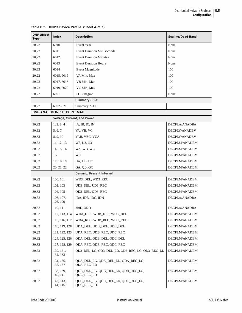
D.11
Date Code 20151012 Instruction Manual SEL-735 Meter
Distributed Network ProtocolConfiguration
20,22 6010 Event Year None
20,22 6011 Event Duration Milliseconds None
20,22 6012 Event Duration Minutes None
20,22 6013 Event Duration Hours None
20,22 6014 Event Magnitude 100
20,22 6015, 6016 VA Min, Max 100
20,22 6017, 6018 VB Min, Max 100
20,22 6019, 6020 VC Min, Max 100
20,22 6021 ITIC Region None
Summary 2–10:
20,22 6022–6210 Summary 2–10
DNP ANALOG INPUT POINT MAP
Voltage, Current, and Power
30,32 1, 2, 3, 4 IA, IB, IC, IN DECPLA/ANADBA
30,32 5, 6, 7 VA, VB, VC DECPLV/ANADBV
30,32 8, 9, 10 VAB, VBC, VCA DECPLV/ANADBV
30,32 11, 12, 13 W3, U3, Q3 DECPLM/ANADBM
30,32 14, 15, 16 WA, WB, WC DECPLM/ANADBM
30,32 16 WC DECPLM/ANADBM
30,32 17, 18, 19 UA, UB, UC DECPLM/ANADBM
30,32 20, 21, 22 QA, QB, QC DECPLM/ANADBM
Demand, Present Interval
30,32 100, 101 WD3_DEL, WD3_REC DECPLM/ANADBM
30,32 102, 103 UD3_DEL, UD3_REC DECPLM/ANADBM
30,32 104, 105 QD3_DEL, QD3_REC DECPLM/ANADBM
30,32 106, 107, 108, 109
IDA, IDB, IDC, IDN DECPLA/ANADBA
30,32 110, 111 3I0D, 3I2D DECPLA/ANADBA
30,32 112, 113, 114 WDA_DEL, WDB_DEL, WDC_DEL DECPLM/ANADBM
30,32 115, 116, 117 WDA_REC, WDB_REC, WDC_REC DECPLM/ANADBM
30,32 118, 119, 120 UDA_DEL, UDB_DEL, UDC_DEL DECPLM/ANADBM
30,32 121, 122, 123 UDA_REC, UDB_REC, UDC_REC DECPLM/ANADBM
30,32 124, 125, 126 QDA_DEL, QDB_DEL, QDC_DEL DECPLM/ANADBM
30,32 127, 128, 129 QDA_REC, QDB_REC, QDC_REC DECPLM/ANADBM
30,32 130, 131, 132, 133
QD3_DEL_LG, QD3_DEL_LD, QD3_REC_LG, QD3_REC_LD DECPLM/ANADBM
30,32 134, 135, 136, 137
QDA_DEL_LG, QDA_DEL_LD, QDA_REC_LG, QDA_REC_LD
DECPLM/ANADBM
30,32 138, 139, 140, 141
QDB_DEL_LG, QDB_DEL_LD, QDB_REC_LG, QDB_REC_LD
DECPLM/ANADBM
30,32 142, 143, 144, 145
QDC_DEL_LG, QDC_DEL_LD, QDC_REC_LG, QDC_REC_LD
DECPLM/ANADBM
Table D.5 DNP3 Device Profile (Sheet 4 of 7)
DNP Object Type
Index Description Scaling/Dead Band

D.12
SEL-735 Meter Instruction Manual Date Code 20151012
Distributed Network ProtocolConfiguration
Demand, Peak
30,32 150, 151 WP3_DEL, WP3_REC DECPLM/ANADBM
30,32 152, 153 UP3_DEL, UP3_REC DECPLM/ANADBM
30,32 154, 155 QP3_DEL, QP3_REC DECPLM/ANADBM
30,32 156, 157, 158, 159
IPA, IPB, IPC, IPN DECPLA/ANADBA
30,32 160, 161 3I0P, 3I2P DECPLA/ANADBA
30,32 162, 163, 164 WPA_DEL, WPB_DEL, WPC_DEL DECPLM/ANADBM
30,32 165, 166, 167 WPA_REC, WPB_REC, WPC_REC DECPLM/ANADBM
30,32 168, 169, 170 UPA_DEL, UPB_DEL, UPC_DEL DECPLM/ANADBM
30,32 171, 172, 173 UPA_REC, UPB_REC, UPC_REC DECPLM/ANADBM
30,32 174, 175, 176 QPA_DEL, QPB_DEL, QPC_DEL DECPLM/ANADBM
30,32 177, 178, 179 QPA_REC, QPB_REC, QPC_REC DECPLM/ANADBM
30,32 180, 181, 182, 183
QP3_DEL_LG, QP3_DEL_LD, QP3_REC_LG, QP3_REC_LD DECPLM/ANADBM
30,32 184, 185, 186, 187
QPA_DEL_LG, QPA_DEL_LD, QPA_REC_LG, QPA_REC_LD DECPLM/ANADBM
30,32 188, 189, 190, 191
QPB_DEL_LG, QPB_DEL_LD, QPB_REC_LG, QPB_REC_LD DECPLM/ANADBM
30,32 192, 193, 194, 195
QPC_DEL_LG, QPC_DEL_LD, QPC_REC_LG, QPC_REC_LD DECPLM/ANADBM
Frequency
30,32 200 FREQ 100/ANADBM
30,32 201 FREQ_PQ 100/ANADBM
Fundamental-Only Voltage, Current, and Power
30,32 300, 301, 302, 303
IA_FUND, IB_FUND, IC_FUND, IN_FUND DECPLA/ANADBA
30,32 304, 305, 306 VA_FUND, VB_FUND, VC_FUND DECPLV/ANADBV
30,32 307, 308, 309 VAB_FUND, VBC_FUND, VCA_FUND DECPLV/ANADBV
30,32 310, 311, 312, 313
IA_ANG, IB_ANG, IC_ANG, IN_ANG 100/ANADBM
30,32 314, 315, 316 VA_ANG, VB_ANG, VC_ANG 100/ANADBM
30,32 317, 318, 319 VAB_ANG, VBC_ANG, VCA_ANG 100/ANADBM
30,32 320, 321, 322 W3_FUND, S3_FUND, Q3_FUND DECPLM/ANADBM
30,32 323, 324, 325 WA_FUND, WB_FUND, WC_FUND DECPLM/ANADBM
30,32 326, 327, 328 SA_FUND, SB_FUND, SC_FUND DECPLM/ANADBM
30,32 329, 330, 331 QA_FUND, QB_FUND, QC_FUND DECPLM/ANADBM
30,32 332, 333, 334, 335
Q3_DEL_LG, Q3_DEL_LD, Q3_REC_LG, Q3_REC_LD DECPLM/ANADBM
30,32 336, 337, 338, 339
QA_DEL_LG, QA_DEL_LD, QA_REC_LG, QA_REC_LD DECPLM/ANADBM
Table D.5 DNP3 Device Profile (Sheet 5 of 7)
DNP Object Type
Index Description Scaling/Dead Band
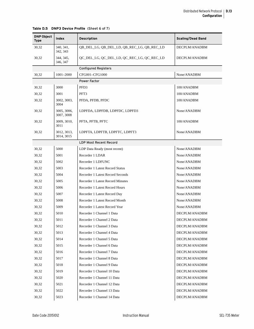
D.13
Date Code 20151012 Instruction Manual SEL-735 Meter
Distributed Network ProtocolConfiguration
30,32 340, 341, 342, 343
QB_DEL_LG, QB_DEL_LD, QB_REC_LG, QB_REC_LD DECPLM/ANADBM
30,32 344, 345, 346, 347
QC_DEL_LG, QC_DEL_LD, QC_REC_LG, QC_REC_LD DECPLM/ANADBM
Configured Registers
30,32 1001–2000 CFG001–CFG1000 None/ANADBM
Power Factor
30,32 3000 PFD3 100/ANADBM
30,32 3001 PFT3 100/ANADBM
30,32 3002, 3003, 3004
PFDA, PFDB, PFDC 100/ANADBM
30,32 3005, 3006, 3007, 3008
LDPFDA, LDPFDB, LDPFDC, LDPFD3 None/ANADBM
30,32 3009, 3010, 3011
PFTA, PFTB, PFTC 100/ANADBM
30,32 3012, 3013, 3014, 3015
LDPFTA, LDPFTB, LDPFTC, LDPFT3 None/ANADBM
LDP Most Recent Record
30,32 5000 LDP Data Ready (most recent) None/ANADBM
30,32 5001 Recorder 1 LDAR None/ANADBM
30,32 5002 Recorder 1 LDFUNC None/ANADBM
30,32 5003 Recorder 1 Latest Record Status None/ANADBM
30,32 5004 Recorder 1 Latest Record Seconds None/ANADBM
30,32 5005 Recorder 1 Latest Record Minutes None/ANADBM
30,32 5006 Recorder 1 Latest Record Hours None/ANADBM
30,32 5007 Recorder 1 Latest Record Day None/ANADBM
30,32 5008 Recorder 1 Latest Record Month None/ANADBM
30,32 5009 Recorder 1 Latest Record Year None/ANADBM
30,32 5010 Recorder 1 Channel 1 Data DECPLM/ANADBM
30,32 5011 Recorder 1 Channel 2 Data DECPLM/ANADBM
30,32 5012 Recorder 1 Channel 3 Data DECPLM/ANADBM
30,32 5013 Recorder 1 Channel 4 Data DECPLM/ANADBM
30,32 5014 Recorder 1 Channel 5 Data DECPLM/ANADBM
30,32 5015 Recorder 1 Channel 6 Data DECPLM/ANADBM
30,32 5016 Recorder 1 Channel 7 Data DECPLM/ANADBM
30,32 5017 Recorder 1 Channel 8 Data DECPLM/ANADBM
30,32 5018 Recorder 1 Channel 9 Data DECPLM/ANADBM
30,32 5019 Recorder 1 Channel 10 Data DECPLM/ANADBM
30,32 5020 Recorder 1 Channel 11 Data DECPLM/ANADBM
30,32 5021 Recorder 1 Channel 12 Data DECPLM/ANADBM
30,32 5022 Recorder 1 Channel 13 Data DECPLM/ANADBM
30,32 5023 Recorder 1 Channel 14 Data DECPLM/ANADBM
Table D.5 DNP3 Device Profile (Sheet 6 of 7)
DNP Object Type
Index Description Scaling/Dead Band

D.14
SEL-735 Meter Instruction Manual Date Code 20151012
Distributed Network ProtocolEIA-232 Physical Layer Operation
EIA-232 Physical Layer OperationThe RTS signal can control an external transceiver. The CTS signal can act as a DCD input, indicating when the medium is in use. Transmissions initiate only if DCD is deasserted. When DCD drops and after the idle time is satisfied, the meter can send the next pending outgoing message. This idle time is random, but is between the minimum and maximum allowed idle times (i.e., MINDLY and MAXDLY).
In addition, the SEL-735 monitors received data and treats receipt of data as a DCD indication. In cases where the external transceiver does not support DCD, you can loop the RTS signal back to the CTS line. When the SEL-735
30,32 5024 Recorder 1 Channel 15 Data DECPLM/ANADBM
30,32 5025 Recorder 1 Channel 16 Data DECPLM/ANADBM
30,32 5026–5050 Recorder 2
30,32 5051–5075 Recorder 3
30,32 5076–5100 Recorder 4
30,32 5101–5125 Recorder 5
30,32 5126–5150 Recorder 6
30,32 5151–5175 Recorder 7
30,32 5176–5200 Recorder 8
30,32 5201–5225 Recorder 9
30,32 5226–5250 Recorder 10
30,32 5251–5275 Recorder 11
30,32 5276–5300 Recorder 12
Event Summary Information
30,32 6000 Event type None/ANADBM
30,32 6001 Event targets None/ANADBM
30,32 6002 Event frequency None/ANADBM
30,32 6003–6005 Event time in DNP format (high, middle, and low 16 bits) None/ANADBM
DNP ANALOG OUTPUT POINT MAP
Remote Analog Outputs
40,41 00–31 RA00–RA31
LDP Recorder and Start-Time Selection
40,41 39 Select LDP Recorder
40,41 40 LDP start record time: Seconds
40,41 41 LDP start record time: Minutes
40,41 42 LDP start record time: Hours
40,41 43 LDP start record time: Day
40,41 44 LDP start record time: Month
40,41 45 LDP start record time: Year
Table D.5 DNP3 Device Profile (Sheet 7 of 7)
DNP Object Type
Index Description Scaling/Dead Band

D.15
Date Code 20151012 Instruction Manual SEL-735 Meter
Distributed Network ProtocolEthernet Operation
transmits a DNP message, it delays transmitting after asserting RTS by at least the time in the PREDLY setting. After transmitting the last byte of the message, the SEL-735 delays for at least PSTDLY ms before deasserting RTS.
If the PSTDLY time delay is in progress (RTS still high) following a transmission, and another transmission initiates, the SEL-735 transmits the message without completing the PSTDLY delay and without any preceding PREDLY delay. Set PREDLY to OFF to completely disable RTS/CTS handshaking. In this case, the meter forces RTS high and ignores CTS, with only received characters acting as a DCD indication. The timing is the same as previously, but PREDLY functions as if it were set to 0, and RTS does not actually deassert after the PSTDLY time delay expires.
Ethernet OperationThe SEL-735 DNP LAN/WAN implementation conforms to DNP3 Specification, Vol. 7, Networking—Transporting DNP3 over Local and Wide Area Networks, Version 2.0, Draft H, 15 December 2004. DNP sessions act as listening end points as defined by the DNP LAN/WAN specification previously referenced.
The DNP-IP response is identical to the serial response, but it requires the following communications-specific settings.
If the UNSOL setting is set to Y, the SEL-735 transmits unsolicited data when either of the following are true.
➤ Initialization is complete and DNPTR = UDP, or
➤ The master has established a session, if DNPTR = TCP.
Table D.6 DNP-IP Specific Settings
Setting Definition RangeDefault Value
EDNP Enable DNP-IP Sessions. Set this value to 0 to disable DNP-IP in the SEL-735.
0–5 0
DNPNUM DNP TCP and UDP Port. Identifies the TCP and UDP port between the master and the SEL-735.
1–65534 excluding 20, 21, 502, and the TPORT setting.
2000
DNPIPn Master IP Address. Set DNPIP = 0.0.0.0 to accept requests from any DNP-IP address.
zzz.yyy.xxx.www 192.168.0.3
DNPTRn Transport Protocol. Selects between TCP and UDP protocols.
TCP, UDP TCP
DNPUDPn UDP Response Port. Selects the port to which the SEL-735 responds. If DNPUDP = REQ, the SEL-735 responds to the port number from the master's UDP request.
REQ, 1–65534 2000

D.16
SEL-735 Meter Instruction Manual Date Code 20151012
Distributed Network ProtocolDNP Channels
DNP ChannelsDNP channels are logical groupings of sessions that share the same DNP data-link and transport layers. All DNP data-link and transport layer settings sharing the same DNP channel are common between the shared sessions. The following settings are the same between shared DNP sessions: Seconds to Data Link Time-Out (DTIMEO) and Data Link Retries (DRETRY). Other settings, specific to the type of channel, may also need to be common across shared DNP sessions. The SEL-735 routes DNP message traffic it receives on a channel with shared sessions to the appropriate session.
All DNP sessions that communicate over the same serial port are on the same DNP channel. The Data Link Time-Out and Data Link Retries settings are common between the shared DNP sessions. Additionally, all serial port settings are common between the shared DNP sessions.
Data Access MethodBased on the capabilities of the system, it is necessary to determine which method you want to use for retrieving data on the DNP connection.
Table D.7 summarizes the main options, listed from least to most efficient, and indicates the corresponding key settings.
Table D.7 Data Access Methods
Data Retrieval Method Description Relevant SEL-735 DNP Settings
Polled Static The master polls for static (Class 0) data only
Set ECLASS = 0
Set UNSOL = N
Polled Report-by-Exception The master polls frequently for event data and occasionally for static data
Set ECLASS to a non-zero value, Set UNSOL = N
Unsolicited Report-by-Exception The slave devices send unsolicited event data to the master, and the master occasionally sends integrity polls for static data
Set ECLASS to a non-zero value
Set UNSOL = Y
Set NUMEVE and AGEEVE to adjust the response rate
Quiescent The master never polls, relies on unsolicited reports only
Set ECLASS to a non-zero value
Set UNSOL = Y
Set NUMEVE and AGEEVE to adjust the response rate

D.17
Date Code 20151012 Instruction Manual SEL-735 Meter
Distributed Network ProtocolDevice Profile
Device ProfileTable D.8 contains the standard DNP3 device profile information. The example device profile in the DNP3 subset definitions replaces traditional device profile checkboxes with presentation of only relevant selections.
Table D.8 SEL-735 DNP3 Device Profile
Parameter Value
Vendor name Schweitzer Engineering Laboratories
Device name SEL-735
Highest DNP request level Level 2
Highest DNP response level Level 2
Device function Slave
Notable objects, functions, and/or qualifiers supported Supports enabling and disabling of unsolicited reports on a class basis
Maximum data link frame size transmitted/received (octets) 292
Maximum data link retries Configurable using DRETRY
Requires data link layer confirmation Configurable using DTIMEO
Maximum application fragment size transmitted/received (octets)
2048
Maximum application layer retries None
Requires application layer confirmation When reporting Event Data
Data link confirm time-out Configurable using DTIMEO
Complete application fragment time-out None
Application confirm time-out Configurable using ETIMEO
Complete Application response time-out None
Executes control WRITE binary outputs Always
Executes control SELECT/OPERATE Always
Executes control DIRECT OPERATE Always
Executes control DIRECT OPERATE-NO ACK Always
Executes control count greater than 1 Never
Executes control Pulse On Always
Executes control Pulse Off Always
Executes control Latch Off Always
Executes control Latch Off Always
Executes control Queue Never
Executes control Clear Queue Never
Reports binary input change events when no specific variation requested
Only time-tagged
Reports time-tagged binary input change events when no specific variation requested
Binary Input change with time
Sends unsolicited responses Configurable using UNSOL
Sends static data in unsolicited responses Never
Default counter object/variation Object 20, Variation 5
Counter roll-over 32 bits
Sends multifragment responses No

D.18
SEL-735 Meter Instruction Manual Date Code 20151012
Distributed Network ProtocolObject Table
Object TableTable D.9 lists the objects and variations with supported function codes and qualifier codes.
Table D.9 SEL-735 DNP Object List (Sheet 1 of 2)
Obj. Var. Description
Request(supported)
Response(may generate)
Funct. Codes (dec)
Qual. Codes (hex)Funct. Codes (dec)
Qual. Codes (hex)
1 0 Binary Input—All Variations 1 0, 1, 6, 7, 8
1 1 Binary Input 1 0, 1, 6, 7, 8, 17, 28 129 0, 1, 17, 28
1 2a Binary Input With Status 1 0, 1, 6, 7, 8, 17, 28 129 0, 1, 17, 28
2 0 Binary Input Change—All Variations 1 6, 7, 8
2 1 Binary Input Change Without Time 1 6, 7, 8 129 17, 28
2 2a Binary Input Change With Time 1 6, 7, 8 129, 130 17, 28
2 3 Binary Input Change With Relative Time 1 6, 7, 8 129 17, 28
10 0 Binary Output—All Variations 1 0, 1, 6, 7, 8 129
10 1 Binary Output 0, 1, 6, 7, 8 129
10 2a Binary Output Status 1 0, 1, 6, 7, 8 129 0, 1
12 1 Control Meter Output Block 3, 4, 5, 6 17, 28 129 Echo of Request
20 0 Binary Counter—All Variations 1, 7, 8 0, 1, 6, 7, 8, 17, 28
20 5a 32-Bit Binary Counter Without Flag 1, 7, 8 0, 1, 6, 7, 8, 17, 28 129 0, 1, 17, 28
20 6 16-Bit Binary Counter Without Flag 1, 7, 8 0, 1, 6, 7, 8, 17, 28 129 0, 1, 17, 28
21 0 Frozen Counter—All Variations 1 0, 1, 6, 7, 8, 17, 28 129 0, 1, 17, 28
21 1a 32-Bit Frozen Counter 1 0, 1, 6, 7, 8, 17, 28 129 0, 1, 17, 28
21 2 16-Bit Frozen Counter 1 0, 1, 6, 7, 8, 17, 28 129 0, 1, 17, 28
21 5 32-Bit Frozen Counter With Time of Freeze 1 0, 1, 6, 7, 8, 17, 28 129 0, 1, 17, 28
21 6 16-Bit Frozen Counter With Time of Freeze 1 0, 1, 6, 7, 8, 17, 28 129 0, 1, 17, 28
22 0 Counter Change Event—All Variations 1 6, 7, 8
22 1 32-Bit Counter Change Event Without Time 1 6, 7, 8 129 17, 28
22 2 16-Bit Counter Change Event Without Time 1 6, 7, 8 129 17, 28
22 5a 32-Bit Counter Change Event With Time 1 6, 7, 8 129, 130 17, 28
22 6 16-Bit Counter Change Event With Time 1 6, 7, 8 129 17, 28
23 0 Frozen Counter Event—All Variations 1 6, 7, 8 129 17, 28
23 1a 32-Bit Frozen Counter Event Without Time 1 6, 7, 8 129, 130 17, 28
23 2 16-Bit Frozen Counter Event Without Time 1 6, 7, 8 129 17, 28
23 5 32-Bit Frozen Counter Event With Time 1 6, 7, 8 129 17, 28
23 6 16-Bit Frozen Counter Event With Time 1 6, 7, 8 129 17, 28
30 0 Analog Input—All Variations 1 0, 1, 6, 7, 8, 17, 28
30 1 32-Bit Analog Input 1 0, 1, 6, 7, 8, 17, 28 129 0, 1, 17, 28
30 2 16-Bit Analog Input 1 0, 1, 6, 7, 8, 17, 28 129 0, 1, 17, 28
30 3 32-Bit Analog Input Without Flag 1 0, 1, 6, 7, 8, 17, 28 129 0, 1, 17, 28
30 4a 16-Bit Analog Input Without Flag 1 0, 1, 6, 7, 8, 17, 28 129 0, 1, 17, 28
32 0 Analog Change Event—All Variations 1 6, 7, 8

D.19
Date Code 20151012 Instruction Manual SEL-735 Meter
Distributed Network ProtocolObject Table
The SEL-735 supports control meter output blocks (Object 12, Variation 1). The control meters correspond to the remote bits and other functions, as shown in Table D.10.
32 1 32-Bit Analog Change Event Without Time 1 6, 7, 8 129 17, 28
32 2a 16-Bit Analog Change Event Without Time 1 6, 7, 8 129, 130 17, 28
32 3 32-Bit Analog Change Event With Time 1 6, 7, 8 129 17, 28
32 4 16-Bit Analog Change Event With Time 1 6, 7, 8 129 17, 28
34 1 16-Bit Analog Reporting Dead Band 1, 2 0, 1, 6, 7, 8, 17, 28 129 0, 1, 17, 28
34 2 32-Bit Analog Reporting Dead Band 1, 2 0, 1, 6, 7, 8, 17, 28 129 0, 1, 17, 28
40 0 Analog Output Status—All Variations 1 0, 1, 6, 7, 8
40 1 32-Bit Analog Output Status 1 0, 1, 6, 7, 8 129 0, 1
40 2a 16-Bit Analog Output Status 1 0, 1, 6, 7, 8 129 0, 1
41 1 32-Bit Analog Output Block 3, 4, 5, 6 17, 28 129 Echo of Request
41 2a 16-Bit Analog Output Block 3, 4, 5, 6 17, 28 129 Echo of Request
50 1 Time and Date 1, 2 7, 8 index=0 129 07, quantity=1
50 3 Time and Date—Absolute time at last recorded time 7, 8 index=0 129 07, quantity=1
51 1 Synchronized Time and Date CTO 07, quantity=1
52 2 Time Delay, Fine 129 07, quantity=1
60 1 Class 0 Data 1 6, 7, 8 17, 28
60 2 Class 1 Data 1, 20, 21 6, 7, 8 17, 28
60 3 Class 2 Data 1, 20, 21 6, 7, 8 17, 28
60 4 Class 3 Data 1, 20, 21 6, 7, 8
80 1 Internal Indications 2 0, 1 index=7
N/A No object required for the following function codes:
13 cold start
14 warm start
23 delay measurement
13, 14, 23
a Default variation.
Table D.10 Control Field (Sheet 1 of 2)
Trip/Close Pairs Code Selection Operation
Index Close (0x4X) Trip (0x8X) Latch On (3) Latch Off (4) Pulse On (1) Pulse Off (2)
30 Pulse RB02 Pulse RB01 Pulse RB02 Pulse RB01 Pulse RB02 Pulse RB01
31 Pulse RB04 Pulse RB03 Pulse RB04 Pulse RB03 Pulse RB04 Pulse RB03
32 Pulse RB06 Pulse RB05 Pulse RB06 Pulse RB05 Pulse RB06 Pulse RB05
33 Pulse RB08 Pulse RB07 Pulse RB08 Pulse RB07 Pulse RB08 Pulse RB07
34 Pulse RB10 Pulse RB09 Pulse RB10 Pulse RB09 Pulse RB10 Pulse RB09
35 Pulse RB12 Pulse RB11 Pulse RB12 Pulse RB11 Pulse RB12 Pulse RB11
36 Pulse RB14 Pulse RB13 Pulse RB14 Pulse RB13 Pulse RB14 Pulse RB13
37 Pulse RB16 Pulse RB15 Pulse RB16 Pulse RB15 Pulse RB16 Pulse RB15
Table D.9 SEL-735 DNP Object List (Sheet 2 of 2)
Obj. Var. Description
Request(supported)
Response(may generate)
Funct. Codes (dec)
Qual. Codes (hex)Funct. Codes (dec)
Qual. Codes (hex)

D.20
SEL-735 Meter Instruction Manual Date Code 20151012
Distributed Network ProtocolObject Table
When the TRIP bit asserts, the SEL-735 performs a latch off operation on the corresponding index. When the CLOSE bit asserts, the SEL-735 performs a latch on operation on the corresponding index. Pulse operations asserts the corresponding index for one processing interval. Exercise caution with multiple remote bit pulses in a single message (i.e., point count > 1), because this can result in the meter disregarding some of the pulse commands and returning an already active status.
40 Read next meter event
Read next meter event
Read next meter event
No action Read next meter event
No action
81–84 Pulse OUT401–OUT404
Pulse OUT401–OUT404
Pulse OUT401–OUT404
Pulse OUT401–OUT404
Pulse OUT401–OUT404
Pulse OUT401–OUT404
85–87 Pulse OUT101–OUT103
Pulse OUT101–OUT103
Pulse OUT101–OUT103
Pulse OUT101–OUT103
Pulse OUT101–OUT103
Pulse OUT101–OUT103
176–183 Set RB08–RB01 Clear RB08–RB01 Set RB08–RB01 Clear RB08–RB01 Pulse RB08–RB01 Clear RB08–RB01
184–191 Set RB16–RB09 Clear RB16–RB09 Set RB16–RB09 Clear RB16–RB09 Pulse RB16–RB09 Clear RB16–RB09
Table D.10 Control Field (Sheet 2 of 2)
Trip/Close Pairs Code Selection Operation
Index Close (0x4X) Trip (0x8X) Latch On (3) Latch Off (4) Pulse On (1) Pulse Off (2)

Date Code 20151012 Instruction Manual SEL-735 Meter
Appendix EModbus Communications Protocol
OverviewThis appendix describes Modbus® communications features that the SEL-735 supports. For a further details on the Modbus protocol, please see the publication: Modicon Modbus Protocol Reference Guide (PI-MBUS-300 Rev. J).
Modbus is a binary protocol that permits communication among a single master device and multiple slave devices. The communication is half duplex; only one device transmits at a time. The master transmits a binary command that includes the address of the desired slave device. All of the slave devices receive the message, but only the slave device with the matching address responds.
The SEL-735 allows a Modbus master device to do the following:
➤ Acquire metering, monitoring, load profile, and event data.
➤ Control output contacts and remote bits.
➤ Read the self-test status and learn the present condition of all the meter protection elements.
Modbus RTU Communications ProtocolModbus Queries Modbus RTU master devices initiate all exchanges by sending a query. The
query consists of the fields shown in Table E.1.
The SLAVEID setting defines the device address. Set this value to a unique number for each device on the Modbus network. For Modbus communication to operate properly, no two slave devices may have the same address.
A cyclical redundancy check detects errors in the received data. If the meter detects an error, it discards the data packet.
Table E.1 Modbus Query Fields
Field Number of Bytes Range
Slave Device Address 1 byte 1–247
Function Code 1 byte Supported Modbus function codes
Data Region 0–251 bytes 0–255 (each byte)
Cyclical Redundancy Check (CRC) 2 bytes 0–65535

E.2
SEL-735 Meter Instruction Manual Date Code 20151012
Modbus Communications ProtocolModbus RTU Communications Protocol
Modbus Responses The slave device sends a response message after it performs the action the query requests. If the slave cannot execute the command for any reason, it sends an error response. Otherwise, the meter formats the slave device response similarly to the query and includes the slave address, function code, data (if applicable), and a cyclical redundancy check value.
Supported Modbus Function Codes
The SEL-735 supports the function codes shown in Table E.2.
Modbus Exception Responses
The SEL-735 returns an exception code under the conditions Table E.3 describes.
In the event that any of the errors listed in Table E.3 occur, the meter assembles a response message that includes the exception code in the data field. The meter sets the most significant bit in the function code field to indicate to the master that the data field contains an exception code, instead of the requested data. Table E.4 shows the format of the exception codes.
Table E.2 Modbus Function Codes
Codes Description
01h Read Coil Status
02h Read Input Status
03h Read Holding Registers
04h Read Input Registers
05h Force Single Coil
06h Preset Single Register
10h Preset Multiple Registers
Table E.3 Modbus Exception Codes
Error Code Error Type Description
01 Illegal Function Code The received function code is either undefined or unsupported.
02 Illegal Data Address The received command contains an unsupported address in the data field.
03 Illegal Data Value The received command contains a value that is out of range.
04 Device Error The SEL-735 is in the wrong state for the requested function.
06 Busy The SEL-735 is unable to process the command at this time because of a busy resource.
08 Memory Error Checksum error on stored data.
Table E.4 Modbus Exception Code Format
Value Number of Bytes
Slave Device Address 1
Function Code (with MSB set) 1
Error Code 1
CRC 1

E.3
Date Code 20151012 Instruction Manual SEL-735 Meter
Modbus Communications ProtocolModbus RTU Communications Protocol
Cyclical Redundancy Check
The SEL-735 uses the device address, function code, and data fields to calculate a 2-byte CRC value. It appends this value to the end of every Modbus response. When the master device receives the response, it recalculates the CRC. If the calculated CRC matches the CRC the SEL-735 sent, the master device uses the data it received. If there is no match, the check fails and the meter ignores the message. The devices use a similar process when the master sends queries.
01h Read Coil Status Command
Use function code 01h to read the On/Off status of the selected bits (coils). You can read the status of as many as 2000 bits per query.
Note that the meter coil addresses start at 0 (e.g., Coil 1 is located at address zero). The coil status is packed one coil per bit of the data field. The least significant bit (LSB) of the first data byte contains the starting coil address in the query. The other coils follow toward the high-order end of this byte and from low order to high order in subsequent bytes.
To build the response, the meter calculates the number of bytes necessary to contain the number of bits the query requested. If the number of bits the query requested is not evenly divisible by eight, the meter adds one more byte to maintain the balance of bits, padded by zeros to make an even byte.
Table E.6 shows responses to 01h query errors.
02h Read Input Status Command
Use function code 02h to read the On/Off status of the selected bits (inputs). You can read the status of as many as 2000 bits per query. Note that the input addresses start at 0 (e.g., Input 1 is located at address zero).
Table E.5 01h Read Coil Status Commands
Bytes Field
Requests from the master must have the following format:
1 byte Slave Address
1 byte Function Code (01h)
2 bytes Address of the First Bit
2 bytes Number of Bits to Read
2 bytes CRC-16
A successful response from the slave has the following format:
1 byte Slave Address
1 byte Function Code (01h)
1 byte Bytes of data (n)
n bytes Data
2 bytes CRC-16
Table E.6 Device Responses to 01h Read Coil Query Errors
Error Error Code ReturnedCommunication Counter Increments
Invalid bit to read Illegal Data Address (02h) Invalid Address
Invalid number of bits to read Illegal Data Value (03h) Illegal Register
Format error Illegal Data Value (03h) Bad Packet Format

E.4
SEL-735 Meter Instruction Manual Date Code 20151012
Modbus Communications ProtocolModbus RTU Communications Protocol
The input status is packed one input per bit of the data field. The LSB of the first data byte contains the starting input address in the query. The other inputs follow towards the high-order end of this byte, and from low order to high order in subsequent bytes.
To build the response, the meter calculates the number of bytes necessary to contain the number of bits the query requested. If the number of bits the query requested is not evenly divisible by eight, the meter adds one more byte to maintain the balance of bits, padded by zeros to make an even byte.
Table E.8 defines input numbers.
In each row, the device assigns input numbers from the right-most input to the left-most input (i.e., Input 1 is N and Input 8 is EN). Input addresses start at 0000 (i.e., Input 1 is located at Input Address 0000).
Table E.9 shows responses to 02h query errors.
Table E.7 02h Read Input Status Command
Bytes Field
Requests from the master must have the following format:
1 byte Slave Address
1 byte Function Code (02h)
2 bytes Address of the First Bit
2 bytes Number of Bits to Read
2 bytes CRC-16
A successful response from the slave will have the following format:
1 byte Slave Address
1 byte Function Code (02h)
1 byte Bytes of data (n)
n bytes Data
2 bytes CRC-16
Table E.8 Device Input Coils
Input Coil Number Input Coil Name Notes
1 IN101
2 IN102
3 IN401 Returns 0 if not installed
4 IN402 Returns 0 if not installed
5 IN403 Returns 0 if not installed
6 IN404 Returns 0 if not installed
Table E.9 Device Responses to 02h Read Input Query Errors
Error Error Code ReturnedCommunication Counter Increments
Invalid bit to read Illegal Data Address (02h) Invalid Address
Invalid number of bits to read Illegal Data Value (03h) Illegal Register
Format error Illegal Data Value (03h) Bad Packet Format

E.5
Date Code 20151012 Instruction Manual SEL-735 Meter
Modbus Communications ProtocolModbus RTU Communications Protocol
03h Read Holding Register Command
Use function code 03h to read directly from the Modbus Register Map shown in Table E.26.
You can read a maximum of 125 registers at once with this function code. Most masters use 4X references with this function code. If you are accustomed to 4X references with this function code, for five-digit addressing, add 40001 to the standard database address.
Table E.11 shows responses to 03h query errors.
04h Read Input Registers Command
Use function code 04h to read from the Modbus Register Map shown in Table E.26.
You can read a maximum of 125 registers at once with this function code. Most masters use 3X references with this function code. If you are accustomed to 3X references with this function code, for five-digit addressing, add 30001 to the standard database address.
Table E.10 03h Read Holding Register Command
Bytes Field
Requests from the master must have the following format:
1 byte Slave Address
1 byte Function Code (03h)
2 bytes Starting Register Address
2 bytes Number of Registers to Read
2 bytes CRC-16
A successful response from the slave will have the following format:
1 byte Slave Address
1 byte Function Code (03h)
1 byte Bytes of data (n)
n bytes Data
2 bytes CRC-16
Table E.11 Device Responses to 03h Read Holding Register Query Errors
Error Error Code ReturnedCommunication Counter Increments
Illegal register to read Illegal Data Address (02h) Invalid Address
Illegal number of registers to read
Illegal Data Value (03h) Illegal Register
Format error Illegal Data Value (03h) Bad Packet Format
Busy Slave is busy with other task (06h)

E.6
SEL-735 Meter Instruction Manual Date Code 20151012
Modbus Communications ProtocolModbus RTU Communications Protocol
Table E.13 shows responses to 04h query errors.
05h Force Single Coil Command
Use function code 05h to set or clear a coil. In Table E.14, the command response is identical to the command request.
Table E.15 lists available coil numbers. The physical coils (coils 1–7) are self-resetting. Pulsing a set remote bit clears the remote bit.
Table E.12 04h Read Holding Register Command
Bytes Field
Requests from the master must have the following format:
1 byte Slave Address
1 byte Function Code (04h)
2 bytes Starting Register Address
2 bytes Number of Registers to Read
2 bytes CRC-16
A successful response from the slave will have the following format:
1 byte Slave Address
1 byte Function Code (04h)
1 byte Bytes of data (n)
n bytes Data
2 bytes CRC-16
Table E.13 Device Responses to 04h Read Holding Register Query Errors
Error Error Code ReturnedCommunication Counter Increments
Illegal register to read Illegal Data Address (02h) Invalid Address
Illegal number of registers to read
Illegal Data Value (03h) Illegal Register
Format error Illegal Data Value (03h) Bad Packet Format
Busy Slave is busy with other task (06h)
Table E.14 05h Force Single Coil Command
Bytes Field
Requests from the master must have the following format:
1 byte Slave Address
1 byte Function Code (05h)
2 bytes Coil Reference
1 byte Operation Code (FF for bit set, 00 for bit clear)
1 byte Placeholder (00)
2 bytes CRC-16

E.7
Date Code 20151012 Instruction Manual SEL-735 Meter
Modbus Communications ProtocolModbus RTU Communications Protocol
Coil addresses start at 0000 (i.e., Coil 1 is located at Coil address 0000). If the meter disables or the breaker jumper is not installed, it responds with Exception Code 4 (Device Error).
Table E.16 shows additional responses to 05h query errors.
06h Preset Single Register Command
The SEL-735 uses this function to allow a Modbus master to write directly to a database register. Refer to the Modbus Register Map in Table E.26 for a list of registers that remote devices can write to using this function code. If you are accustomed to 4X references with this function code, for six-digit addressing, add 400001 to the standard database addresses.
In Table E.17, the command response is identical to the command request.
Table E.18 shows responses to 06h query errors.
Table E.15 SEL-735 Device Output Coils (FC05h)
Output Coil Number Output Coil Name Note
1–3 OUT101–OUT103
4–7 OUT401–OUT404 Returns 0 if not installed
8–23 RB01–RB16
24–39 Pulse RB01–Pulse RB16
Table E.16 Device Responses to 05h Force Singe Coil Query Errors
Error Error Code ReturnedCommunication Counter Increments
Invalid bit (coil) number Illegal Data Address (02h) Invalid Address
Illegal bit state requested Illegal Data Value (03h) Illegal FunctionCode/Op Code
Format error Illegal Data Value (03h) Bad Packet Format
Table E.17 06h Preset Single Register Command
Bytes Field
Requests from the master must have the following format:
1 byte Slave Address
1 byte Function Code (06h)
2 bytes Register Address
2 bytes Data
2 bytes CRC-16
Table E.18 Device Responses to 06h Preset Single Register Query Errors
Error Error Code ReturnedCommunication Counter Increments
Illegal register address Illegal Data Address (02h) Invalid Address Illegal Write
Illegal register value Illegal Data Value (03h) Illegal Write
Format error Illegal Data Value (03h) Bad Packet Format
Device error Invalid Access Level (04h) None

E.8
SEL-735 Meter Instruction Manual Date Code 20151012
Modbus Communications ProtocolModbus RTU Communications Protocol
10h Preset Multiple Registers Command
This function code works similarly to code 06h, except that it allows as many as 100 writes (per operation) to registers. Refer to the Modbus Register Map, Control I/O Commands, in Table E.26 for a list of registers that remote devices can write to using this function code. If you are accustomed to 4X references with the function code, for six-digit addressing, simply add 400001 to the standard database addresses.
Table E.20 shows responses to 10h query errors.
Modbus Password Control and Parameter Modification
The SEL-735 parameters MID, TID, Password, Device Time, and the User Map Registers are settable via Modbus. Any settable parameter or reset that requires a valid password write will time out 15 minutes after the last valid write to any of these restricted registers.
Writing the password for access level change requires the 10h (preset multiple register) command. Using this command, remote devices can write new passwords one register at a time. The meter returns an error during setting saves if the meter is disabled or when settings are being changed from another port. It also returns a device error for attempts to write to settable values if the access level has not been changed.
Table E.19 10h Preset Multiple Registers Command
Bytes Field
Requests from the master must have the following format:
1 byte Slave Address
1 byte Function Code (10h)
2 bytes Starting Address
2 bytes Number of Registers to Write
1 byte Bytes of Data (n)
n bytes Data
2 bytes CRC-16
A successful response from the slave will have the following format:
1 byte Slave Address
1 byte Function Code (10h)
2 bytes Starting Address
2 bytes Number of Registers
2 bytes CRC-16
Table E.20 Device Responses to 10h Preset Multiple Registers Query Errors
Error Error Code ReturnedCommunication Counter Increments
Illegal register to set Illegal Data Address (02h) Invalid Address Illegal Write
Illegal number of registers to set
Illegal Data Value (03h) Illegal Register Illegal Write
Incorrect number of bytes in query data region
Illegal Data Value (03h) Bad Packet Format Illegal Write
Invalid register data value Illegal Data Value (03h) Illegal Write

E.9
Date Code 20151012 Instruction Manual SEL-735 Meter
Modbus Communications ProtocolModbus RTU Communications Protocol
To enable modification of the settable parameters, remote devices must write a valid Access Level E (EAC) password to the password registers using function code 10h. Note that changing the password changes the password for all ports.
Once you have written a valid password, change the values by using standard single or multiple register writes (06h or 10h). Until you issue a save or discard settings command, the value the device returns when reading the settable parameter registers is a temporary copy.
To save the modified parameters, write a 0x0001 to the Save Settings register of the Control I/O region. This is the only method by which you can save the changes.
To discard settings, either write a 0x0001 to the Discard Settings Changes register of the Control I/O region, write a 0x0001 to the Drop Access Level register of the Control I/O region, or wait 15 minutes since last write for access level time-out.
Modbus Sequential Event Recorder Register Operation
You can read the Sequential Event Recorder through Modbus communications channels. The Modbus register Selected Starting Record sets the starting record to read from the device.
Certain SER Modbus registers use enumerations. See Table E.25 for the definitions.
To obtain SER records from the Modbus register map, perform the following steps.
Step 1. Write to the Selected Starting Record (address 216) register of the SER region of the map the date and time of the first record you want.
Step 2. Read the Number of Records Available register to determine how many SER records are available on or after the selected date and time.
Ten records are available for reading from the SER region of the map.
Step 3. Write to the Selected Starting Record register to select additional records from the number available.
For example, if the number of records available is 25, write 11 to the selected starting record to read records 11 to 20.
Modbus Load Profile Register Operation
You can read load profile recorders through Modbus communications channels. The Modbus register Select Load Profile Recorder sets the LDP recorder from which the device will read. By default, the register is set to one, which selects LDP recorder 1. You can also read the status of each load profile record.
Certain load profile registers are enumerated and bitmapped. See Table E.25 and Table E.26 for the definitions.

E.10
SEL-735 Meter Instruction Manual Date Code 20151012
Modbus Communications ProtocolModbus TCP
To read load profile data from the SEL-735, perform the following steps.
Step 1. If reading an SEL-735 that supports as many as 12 independent LDP recorders, set the LDP recorder you want to read from. If reading an SEL-735 that supports only one LDP recorder, skip to Step 2.
Write the LDP recorder number to the Select Load Profile Recorder register (address 5000). For example, to read LDP recorder 12, write 12 to the register.
Step 2. Read the LDP selected recorder channel name registers from the Load Profile section of the Modbus map. These register addresses range from 5020 to 5170.
These names return as a NULL-terminated ASCII string and provides the human-readable label for the profiled data. If the load profile channel is unused, then the associated label is an empty string.
Step 3. Write to the Starting Record Time/Date registers of the Load Profile region of the map the date and time for the first record you want. The Starting Record register addresses range from 5180 to 5185.
Step 4. Read Record 1 Channel n Data registers to get the value of the first record of the selected LDP recorder, where n is your desired channel number selection from 1 through 16. The Record 1 Channel n Data register addresses range from 5193 to 5223.
As many as 100 records are available on or after the selected date and time. Channels that are not profiling data return a reserved value when you read them (see Table E.22).
Step 5. Read the remaining records from the selected LDP recorder. The Record 2–100 register addresses range from 5225 to 9085.
Modbus TCPModbus TCP is available over Ethernet, SEL-735 Port 1, TCP Port 502. Determine appropriate Ethernet port settings (i.e., IP, Default Router, and Subnet Mask) for your network. The SEL-735 Ethernet port supports five simultaneous Modbus sessions.
Table E.21 defines the specific format of Modbus TCP messages.
Table E.21 Modbus TCP Message Format
Byte 0 Byte 1 Byte 2 Byte 3 Byte 4 Byte 5 Byte 6 Byte 7 Byte 8
TIDU TIDL P1DU PIDL LENU LENL UNITID FC DATA

E.11
Date Code 20151012 Instruction Manual SEL-735 Meter
Modbus Communications ProtocolModbus Data Types
Table E.22 defines the quantities of the Modbus TCP message shown in Table E.21.
Modbus Data TypesTable E.23 shows the data types that the SEL-735 supports. Each Modbus register is 2 bytes long, 16 bits. Data types that require more than 2 bytes use more than one register. For example, STRING data types use many registers to represent the string value. The Meter Identifier string includes 11 registers.
Table E.22 Modbus TCP Message Format Definitions
Field Definition Server Action Notes
TIDU Transaction Identifier Upper Copied into response
TIDL Transaction Identifier Lower Copied into response
PIDU Protocol Identifier Upper Copied into response Always zero
PIDL Protocol Identifier Lower Copied into response Always zero
LENU Data Length Upper Copied into response Always zero (messages are less than 256 bytes)
LENL Data Length Lower Length of response data in bytes
UNITID Unit Identifier Copied into response
FC Function Code Copied into response if no error, high bit set if error condition
Follows Modbus TRU rules
DATA Response Data The request data or error code
Table E.23 Modbus Data Types
Conversiona
a Replace x with 10, 100, or 1000. Replace y with 10, 100, 1000, or 10000.
Description RangeNumber of Registers Used
INT Integer, signed –32767 to 32767 1
INTx Integer, signed with scale factor x –32767 to 32767 1
UINT Integer, unsigned 0 to 65535 1
UNITx Integer, unsigned with scale factor x 0 to 65535 1
LONG Long, signed –2147483647 to 2147483647 2
LONGy Long, signed with scale factor y –2147483647 to 2147483647 2
BITMAP Bitmapped value. Represents binary data. 0 to 65535 1
ENUM Enumerated value. See Table E.24 for definitions. 0 to 65535 1
STRING A null-terminated ASCII string ASCII characters Variable

E.12
SEL-735 Meter Instruction Manual Date Code 20151012
Modbus Communications ProtocolModbus Data Types
Modbus Enumerated Registers (ENUM)
Some Modbus registers include enumerations that use a value to convey specific data. Table E.24 shows the enumerated Modbus registers and the definitions of each.
Modbus Bitmapped Registers (BITMAP)
Some Modbus registers use bitmaps to convey specific data. Bitmapped registers are different from enumerated registers in that each bit has a specific definition, while enumerated register values contain the definition.
Table E.24 Modbus Enumeration Definitions
Enumerated RegistersRegister Addresses
Value Definition
Meter Form 62 0 Meter Form 9
1 Meter Form 5
2 Meter Form 36
BATT, TEMP, Diagnostic status
180, 181 0 OK
1 WARN
2 FAIL
Time Source 206 0 Internal
1 External
Selected record: Type 218 0 Device settings changed
1 Power restored
2 Power loss
3 Time change greater than TIME_CHG.
4 Automatic daylight-saving time change occurred
0x1yyy Device Word bit yyy deasserted, yyy is the Device Word bit number
0x2yyy Device Word bit yyy asserted, yyy is the Device Word bit number
0x8000 Invalid record
Selected recorder channel function LDFUNC
5002 0 End of Interval (EOI)
1 Average (AVG)
2 Change Over Interval (COI)
3 Maximum During Interval (MAX)
4 Minimum During Interval (MIN)
Table E.25 Modbus BITMAP Definitions
Enumerated RegistersRegister Addresses
Bit Definition
Record n: Status 5186... 0 Daylight-saving time in effect
1 Power loss during the interval
2 Time set forward
3 Time set backward
4 Skipped interval
5 Test mode active during interval
Device Word bit status 100–149 N/A Each register contains one Device Word bit row, located in the most significant byte of the register.

E.13
Date Code 20151012 Instruction Manual SEL-735 Meter
Modbus Communications ProtocolModbus Register Map
Modbus Register MapTable E.26 shows each Modbus register address, the register name, any notes pertaining to the register, the read/write access, and the data type of the register.
Table E.26 Modbus Register Map (Sheet 1 of 10)
AddressName Notes
Read (R)Write (W)
Data TypesDecimal Hexadecimal
Device Configuration
0–19 0000–0013 Firmware Identifier SEL FID String R STRING
20–39 0014–0027 Serial Number Meter ID String R STRING
40–50 0028–0032 Meter Identifier RW STRING
51–61 0033–003D Terminal Identifier RW STRING
62 003E Meter Form R ENUM
63–64 003F–0040 Current Transformer Ratio R LONG10000
65–66 0041–0042 Neutral Current Transformer Ratio R LONG10000
67–68 0043–0044 Potential Transformer Ratio R LONG 10000
69 0045 Reserved R UINT
Control and I/O Commands
70–74 0046–004A Password W STRING
75 004B Drop Access Level W UINT
76 004C Save Settings W UINT
77 004D Discard Settings Changes W UINT
78 004E Reset Communication Counters W UINT
79 004F Reset Max/Min Values W UINT
80 0050 Reset Peak Demand W UINT
81 0051 Reserved R UINT
Status
100–149 0064–0095 Device Word Bit Status R BITMAP
150–159 0096–009F Reserved R UINT
Communication Counters
160 00A0 Num Msgs Rx R UINT
161 00A1 Num Msgs Sent to Other Devices R UINT
162 00A2 Invalid Address R UINT
163 00A3 Bad CRC R UINT
164 00A4 UART ERROR R UINT
165 00A5 Illegal Function or Op code R UINT
166 00A6 Illegal Register R UINT
167 00A7 Illegal Write R UINT
168 00A8 Bad Packet Format R UINT
169 00A9 Bad Packet Length R UINT
170–179 00AA–00B3 Reserved R UINT

E.14
SEL-735 Meter Instruction Manual Date Code 20151012
Modbus Communications ProtocolModbus Register Map
Diagnostics
180 00B4 BATT R ENUM
181 00B5 TEMP R ENUM
182 00B6 Reserved R UINT
Time
200 00C8 Present Device Time: Seconds RW UINT
201 00C9 Present Device Time: Minutes RW UINT
202 00CA Present Device Time: Hours RW UINT
203 00CB Present Device Time: Day RW UINT
204 00CC Present Device Time: Month RW UINT
205 00CD Present Device Time: Year RW UINT
206 00CE Time Source R ENUM
207–209 00CF–00D1 Reserved R UINT
Sequential Events Recorder
210 00D2 Start Record: Seconds RW UINT
211 00D3 Start Record: Minutes RW UINT
212 00D4 Start Record: Hours RW UINT
213 00D5 Start Record: Day RW UINT
214 00D6 Start Record: Month RW UINT
215 00D7 Start Record: Year RW UINT
216 00D8 Selected Starting Record RW UINT
217 00D9 Number of Records Available R UINT
218 00DA Start Record: Type R ENUM
219 00DB Start Record: Milliseconds R UINT
220 00DC Start Record: Minutes R UINT
221 00DD Start Record: Hours R UINT
222 00DE Start Record: Day R UINT
223 00DF Start Record: Month R UINT
224 00E0 Start Record: Year R UINT
225–231 00FF–00E7 Selected Record + 1
232–238 00E8–00EE Selected Record + 2
239–245 00EF–00F5 Selected Record + 3
246–252 00F6–00FC Selected Record + 4
253–259 00FD–0103 Selected Record + 5
260–266 0104–010A Selected Record + 6
267–273 010B–0111 Selected Record + 7
247–280 0112–0118 Selected Record + 8
281–287 0119–011F Selected Record + 9
288–349 0120–015D Reserved R UINT
Table E.26 Modbus Register Map (Sheet 2 of 10)
AddressName Notes
Read (R)Write (W)
Data TypesDecimal Hexadecimal
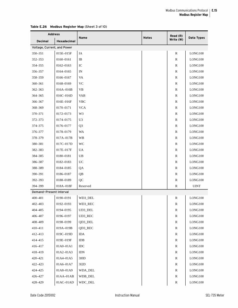
E.15
Date Code 20151012 Instruction Manual SEL-735 Meter
Modbus Communications ProtocolModbus Register Map
Voltage, Current, and Power
350–351 015E–015F IA R LONG100
352–353 0160–0161 IB R LONG100
354–355 0162–0163 IC R LONG100
356–357 0164–0165 IN R LONG100
358–359 0166–0167 VA R LONG100
360–361 0168–0169 VC R LONG100
362–363 016A–016B VB R LONG100
364–365 016C–016D VAB R LONG100
366–367 016E–016F VBC R LONG100
368–369 0170–0171 VCA R LONG100
370–371 0172–0173 W3 R LONG100
372–373 0174–0175 U3 R LONG100
374–375 0176–0177 Q3 R LONG100
376–377 0178–0179 WA R LONG100
378–379 017A–017B WB R LONG100
380–381 017C–017D WC R LONG100
382–383 017E–017F UA R LONG100
384–385 0180–0181 UB R LONG100
386–387 0182–0183 UC R LONG100
388–389 0184–0185 QA R LONG100
390–391 0186–0187 QB R LONG100
392–393 0188–0189 QC R LONG100
394–399 018A–018F Reserved R UINT
Demand—Present Interval
400–401 0190–0191 WD3_DEL R LONG100
402–403 0192–0193 WD3_REC R LONG100
404–405 0194–0195 UD3_DEL R LONG100
406–407 0196–0197 UD3_REC R LONG100
408–409 0198–0199 QD3_DEL R LONG100
410–411 019A–019B QD3_REC R LONG100
412–413 019C–019D IDA R LONG100
414–415 019E–019F IDB R LONG100
416–417 01A0–01A1 IDC R LONG100
418–419 01A2–01A3 IDN R LONG100
420–421 01A4–01A5 3I0D R LONG100
422–423 01A6–01A7 3I2D R LONG100
424–425 01A8–01A9 WDA_DEL R LONG100
426–427 01AA–01AB WDB_DEL R LONG100
428–429 01AC–01AD WDC_DEL R LONG100
Table E.26 Modbus Register Map (Sheet 3 of 10)
AddressName Notes
Read (R)Write (W)
Data TypesDecimal Hexadecimal

E.16
SEL-735 Meter Instruction Manual Date Code 20151012
Modbus Communications ProtocolModbus Register Map
430–431 01AE–01AF WDA_REC R LONG100
432–433 01B0–01B1 WDB_REC R LONG100
434–435 01B2–01B3 WDC_REC R LONG100
436–437 01B4–01B5 UDA_DEL R LONG100
438–489 01B6–01B7 UDB_DEL R LONG100
440–441 01B8–01B9 UDC_DEL R LONG100
442–443 01BA–01BB UDA_REC R LONG100
444–445 01BC–01BD UDB_REC R LONG100
446–447 01BE–01BF UCD_REC R LONG100
448–449 01C0–01C1 QDA_DEL R LONG100
450–451 01C2–01C2 QDB_DEL R LONG100
452–453 01C6–01C7 QDC_REC R LONG100
454–455 01C8–01C9 QDA_REC R LONG100
456–457 01C8–01C9 QDB_REC R LONG100
458–459 01CA–01CB QDC_REC R LONG100
460–461 01CC–01CD QD3_DEL_LG R LONG100
462–463 01CD–01CF QD3_DEL_LD R LONG100
464–465 01D0–01D1 QD3_REC_LG R LONG100
466–467 01D2–01D3 QD3_REC_LD R LONG100
468–469 01D4–01D5 QDA_DEL_LG R LONG100
470–471 01D6–01D7 QDA_DEL_LD R LONG100
472–473 01D8–01D9 QDA_REC_LG R LONG100
474–475 01DA–01DB QDA_REC_LD R LONG100
476–477 01DC–01DD QDB_DEL_LG R LONG100
478–479 01DE–01DF QDB_DEL_LD R LONG100
480–481 01E0–01E1 QDB_REC_LG R LONG100
482–483 01E2–01E3 QDB_REC_LD R LONG100
484–485 01E4–01E5 QDC_DEL_LG R LONG100
486–487 01E6–01E7 QDC_DEL_LD R LONG100
488–489 01E8–01E9 QDC_REC_LG R LONG100
490–491 01EA–01EB QDC_REC_LD R LONG100
492–499 01EC–01ED Reserved R UINT
Demand—Peak
500–501 01F4–01F5 WP3_DEL R LONG100
502–503 01F6–01F7 WP3_REC R LONG100
504–505 01F8–01F9 UP3_DEL R LONG100
506–507 01FA–01FB UP3_REC R LONG100
508–509 01FC–01FD QP3_DEL R LONG100
510–511 01FE–01FF QP3_REC R LONG100
512–513 0200–0201 IDA R LONG100
Table E.26 Modbus Register Map (Sheet 4 of 10)
AddressName Notes
Read (R)Write (W)
Data TypesDecimal Hexadecimal

E.17
Date Code 20151012 Instruction Manual SEL-735 Meter
Modbus Communications ProtocolModbus Register Map
514–515 0202–0203 IDB R LONG100
516–517 0204–0205 IDC R LONG100
518–519 0206–0207 IDN R LONG100
520–521 0208–0209 3I0P R LONG100
522–523 020A–200B 3I2P R LONG100
524–525 020C–020D WPA_DEL R LONG100
527–527 020E–020F WPB_DEL R LONG100
528–529 0210–0211 WPC_DEL R LONG100
530–531 0212–0213 WPA_REC R LONG100
532–533 0214–0215 WPB_REC R LONG100
534–535 0216–0217 WPC_REC R LONG100
536–537 0218–0219 UPA_DEL R LONG100
538–539 021A–021B UPB_DEL R LONG100
540–541 021C–021D UPC_DEL R LONG100
542–543 021E–021F UPA_REC R LONG100
544–545 0220–0221 UPB_REC R LONG100
546–547 0222–0223 UPC_REC R LONG100
548–549 0224–0225 QPA_DEL R LONG100
550–551 0226–0227 QPB_DEL R LONG100
552–553 0228–0229 QPC_DEL R LONG100
554–555 022A–022B QPA_REC R LONG100
556–557 022C–022D QPB_REC R LONG100
558–559 022E–022F QPC_REC R LONG100
560–561 0230–0231 QP3_DEL_LG R LONG100
562–563 0232–0233 QP3_DEL_LD R LONG100
564–565 0234–0235 QP3_REC_LG R LONG100
566–567 0236–0237 QP3_REC_LD R LONG100
568–569 0238–0239 QPA_DEL_LG R LONG100
570–571 023A–023B QPA_DEL_LD R LONG100
572–573 023C–023D QPA_REC_LG R LONG100
574–575 023E–023F QPA_REC_LD R LONG100
576–577 0240–0241 QPB_DEL_LG R LONG100
578–579 0242–0243 QPB_DEL_LD R LONG100
580–581 0244–0245 QPB_REC_LG R LONG100
582–583 0246–0247 QPB_REC_LD R LONG100
584–585 0248–0249 QPC_DEL_LG R LONG100
586–587 024A–024B QPC_DEL_LD R LONG100
588–589 024C–024D QPC_REC_LG R LONG100
590–591 024E–024F QPC_REC_LD R LONG100
592–599 0250–0257 Reserved R UINT
Table E.26 Modbus Register Map (Sheet 5 of 10)
AddressName Notes
Read (R)Write (W)
Data TypesDecimal Hexadecimal
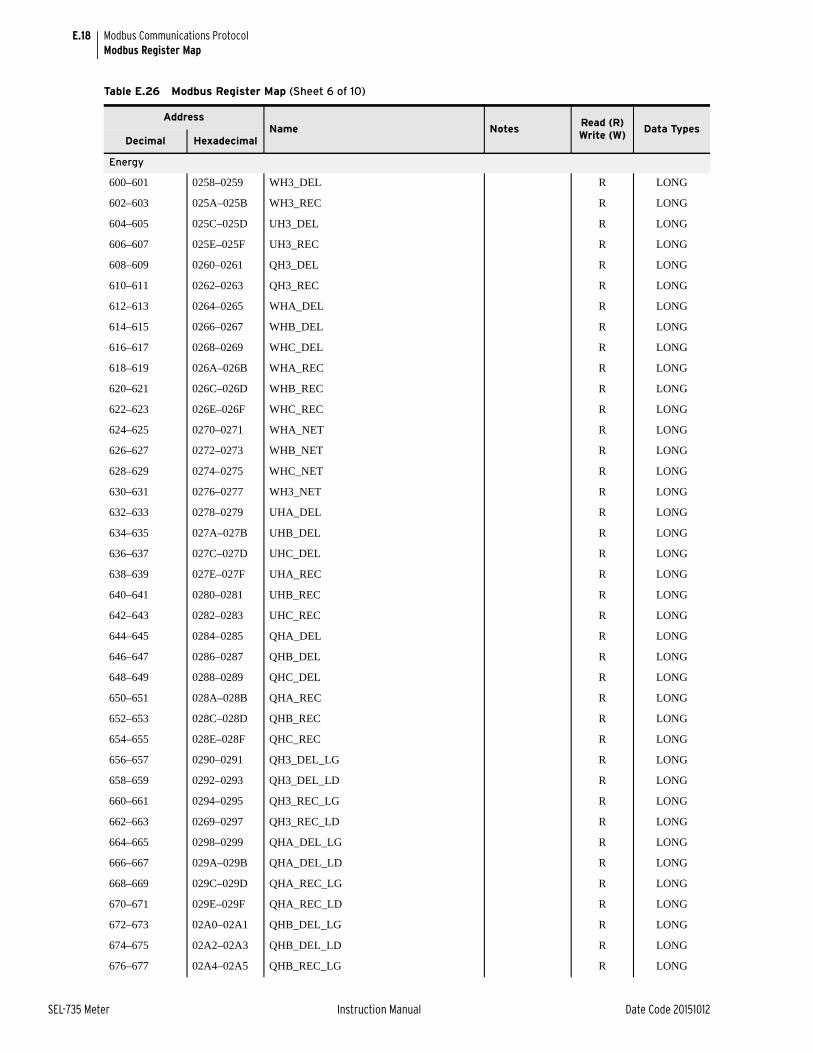
E.18
SEL-735 Meter Instruction Manual Date Code 20151012
Modbus Communications ProtocolModbus Register Map
Energy
600–601 0258–0259 WH3_DEL R LONG
602–603 025A–025B WH3_REC R LONG
604–605 025C–025D UH3_DEL R LONG
606–607 025E–025F UH3_REC R LONG
608–609 0260–0261 QH3_DEL R LONG
610–611 0262–0263 QH3_REC R LONG
612–613 0264–0265 WHA_DEL R LONG
614–615 0266–0267 WHB_DEL R LONG
616–617 0268–0269 WHC_DEL R LONG
618–619 026A–026B WHA_REC R LONG
620–621 026C–026D WHB_REC R LONG
622–623 026E–026F WHC_REC R LONG
624–625 0270–0271 WHA_NET R LONG
626–627 0272–0273 WHB_NET R LONG
628–629 0274–0275 WHC_NET R LONG
630–631 0276–0277 WH3_NET R LONG
632–633 0278–0279 UHA_DEL R LONG
634–635 027A–027B UHB_DEL R LONG
636–637 027C–027D UHC_DEL R LONG
638–639 027E–027F UHA_REC R LONG
640–641 0280–0281 UHB_REC R LONG
642–643 0282–0283 UHC_REC R LONG
644–645 0284–0285 QHA_DEL R LONG
646–647 0286–0287 QHB_DEL R LONG
648–649 0288–0289 QHC_DEL R LONG
650–651 028A–028B QHA_REC R LONG
652–653 028C–028D QHB_REC R LONG
654–655 028E–028F QHC_REC R LONG
656–657 0290–0291 QH3_DEL_LG R LONG
658–659 0292–0293 QH3_DEL_LD R LONG
660–661 0294–0295 QH3_REC_LG R LONG
662–663 0269–0297 QH3_REC_LD R LONG
664–665 0298–0299 QHA_DEL_LG R LONG
666–667 029A–029B QHA_DEL_LD R LONG
668–669 029C–029D QHA_REC_LG R LONG
670–671 029E–029F QHA_REC_LD R LONG
672–673 02A0–02A1 QHB_DEL_LG R LONG
674–675 02A2–02A3 QHB_DEL_LD R LONG
676–677 02A4–02A5 QHB_REC_LG R LONG
Table E.26 Modbus Register Map (Sheet 6 of 10)
AddressName Notes
Read (R)Write (W)
Data TypesDecimal Hexadecimal

E.19
Date Code 20151012 Instruction Manual SEL-735 Meter
Modbus Communications ProtocolModbus Register Map
678–679 02A6–02A7 QHB_REC_LD R LONG
680–681 02A8–02A9 QHC_DEL_LG R LONG
682–683 02AA–02AB QHC_DEL_LD R LONG
684–684 02AC–02AD QHC_REC_LG R LONG
686–687 02AE–02AF QHC_REC_LD R LONG
688–689 02B0–02B1 VHA R LONG
690–691 02B2–02B3 VHB R LONG
692–693 02B4–02B5 VHC R LONG
694–695 02B6–02B7 VH3 R LONG
696–697 02B8–02B9 IHA R LONG
698–699 02BA–02BB IHB R LONG
700–701 02BC–02BD IHC R LONG
702–703 02BE–02BF IHN R LONG
704–705 02C0–02C1 IH3 R LONG
706–899 02C2–0383 Reserved R UINT
Frequency
900 0384 FREQ R UINT100
901 0385 FREQ_PQ R UINT100
902–909 0386–038D Reserved R UINT
Power Factor
910 038F PFD3 R INT100
911 038F PFT3 R INT100
912 0390 PFDA R INT100
913 0391 PFDB R INT100
914 0392 PFDC R INT100
915 0393 LDPFDA R UINT
916 0394 LDPFDB R UINT
917 0395 LDPFDC R UINT
918 0396 LDPFD3 R UINT
919 0397 PFTA R INT100
920 0398 PFTB R INT100
921 0399 PFTC R INT100
922 039A LDPFTA R UINT
923 039B LDPFTB R UNIT
924 039C LDPFTC R UINT
925 039D LDPFT3 R UINT
926–999 039E–03E7 Reserved R UINT
Table E.26 Modbus Register Map (Sheet 7 of 10)
AddressName Notes
Read (R)Write (W)
Data TypesDecimal Hexadecimal
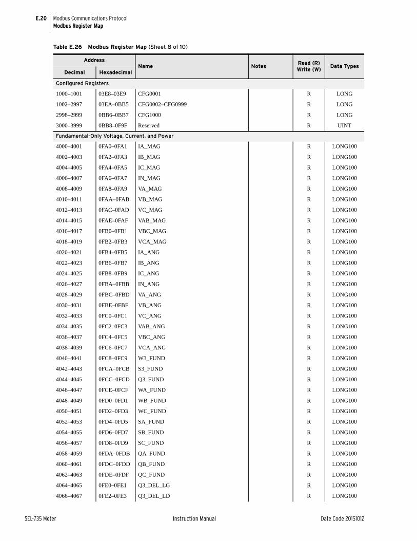
E.20
SEL-735 Meter Instruction Manual Date Code 20151012
Modbus Communications ProtocolModbus Register Map
Configured Registers
1000–1001 03E8–03E9 CFG0001 R LONG
1002–2997 03EA–0BB5 CFG0002–CFG0999 R LONG
2998–2999 0BB6–0BB7 CFG1000 R LONG
3000–3999 0BB8–0F9F Reserved R UINT
Fundamental-Only Voltage, Current, and Power
4000–4001 0FA0–0FA1 IA_MAG R LONG100
4002–4003 0FA2–0FA3 IB_MAG R LONG100
4004–4005 0FA4–0FA5 IC_MAG R LONG100
4006–4007 0FA6–0FA7 IN_MAG R LONG100
4008–4009 0FA8–0FA9 VA_MAG R LONG100
4010–4011 0FAA–0FAB VB_MAG R LONG100
4012–4013 0FAC–0FAD VC_MAG R LONG100
4014–4015 0FAE–0FAF VAB_MAG R LONG100
4016–4017 0FB0–0FB1 VBC_MAG R LONG100
4018–4019 0FB2–0FB3 VCA_MAG R LONG100
4020–4021 0FB4–0FB5 IA_ANG R LONG100
4022–4023 0FB6–0FB7 IB_ANG R LONG100
4024–4025 0FB8–0FB9 IC_ANG R LONG100
4026–4027 0FBA–0FBB IN_ANG R LONG100
4028–4029 0FBC–0FBD VA_ANG R LONG100
4030–4031 0FBE–0FBF VB_ANG R LONG100
4032–4033 0FC0–0FC1 VC_ANG R LONG100
4034–4035 0FC2–0FC3 VAB_ANG R LONG100
4036–4037 0FC4–0FC5 VBC_ANG R LONG100
4038–4039 0FC6–0FC7 VCA_ANG R LONG100
4040–4041 0FC8–0FC9 W3_FUND R LONG100
4042–4043 0FCA–0FCB S3_FUND R LONG100
4044–4045 0FCC–0FCD Q3_FUND R LONG100
4046–4047 0FCE–0FCF WA_FUND R LONG100
4048–4049 0FD0–0FD1 WB_FUND R LONG100
4050–4051 0FD2–0FD3 WC_FUND R LONG100
4052–4053 0FD4–0FD5 SA_FUND R LONG100
4054–4055 0FD6–0FD7 SB_FUND R LONG100
4056–4057 0FD8–0FD9 SC_FUND R LONG100
4058–4059 0FDA–0FDB QA_FUND R LONG100
4060–4061 0FDC–0FDD QB_FUND R LONG100
4062–4063 0FDE–0FDF QC_FUND R LONG100
4064–4065 0FE0–0FE1 Q3_DEL_LG R LONG100
4066–4067 0FE2–0FE3 Q3_DEL_LD R LONG100
Table E.26 Modbus Register Map (Sheet 8 of 10)
AddressName Notes
Read (R)Write (W)
Data TypesDecimal Hexadecimal

E.21
Date Code 20151012 Instruction Manual SEL-735 Meter
Modbus Communications ProtocolModbus Register Map
4068–4069 0FE4–0FE5 Q3_REC_LG R LONG100
4070–4071 0FE6–0FE7 Q3_REC_LD R LONG100
4072–4073 0FE8–0FE9 QA_DEL_LG R LONG100
4074–4075 0FEA–0FEB QA_DEL_LD R LONG100
4076–4077 0FEC–0FED QA_REC_LG R LONG100
4078–4079 0FEE–0FEF QA_REC_LD R LONG100
4080–4081 0FF0–0FF1 QB_DEL_LG R LONG100
4082–4083 0FF2–0FF3 QB_DEL_LD R LONG100
4084–4085 0FF4–0FF5 QB_REC_LG R LONG100
4086–4087 0FF6–0FF7 QB_REC_LD R LONG100
4088–4089 0FF8–0FF9 QC_DEL_LG R LONG100
4090–4091 0FFA–0FFB QC_DEL_LD R LONG100
4092–4093 0FFC–0FFD QC_REC_LG R LONG100
4094–4095 0FFE–0FFF QC_REC_LD R LONG100
4096–4999 1000–1387 Reserved R UINT
Load Profile
5000 1388 Select Load Profile Recorder RW UINT
5001 1389 Selected Recorder Interval Duration (seconds) R UINT
5002 138A Selected Recorder Channel Function R ENUM
5003–5019 138B–0139B Reserved R UINT
5020–5029 139C–13A5 LDP Selected Recorder Channel 1 Name R STRING
5030–5039 13A6–13AF LDP Selected Recorder Channel 2 Name R STRING
5040–5049 13B0–13B9 LDP Selected Recorder Channel 3 Name R STRING
5050–5059 13BA–13C3 LDP Selected Recorder Channel 4 Name R STRING
5060–5069 13C4–13CD LDP Selected Recorder Channel 5 Name R STRING
5070–5079 13CE–13D7 LDP Selected Recorder Channel 6 Name R STRING
5080–5089 13D8–13E1 LDP Selected Recorder Channel 7 Name R STRING
5090–5099 13E2–13EB LDP Selected Recorder Channel 8 Name R STRING
5100–5109 13EC–13F5 LDP Selected Recorder Channel 9 Name R STRING
5110–5119 13F6–13FF LDP Selected Recorder Channel 10 Name R STRING
5120–5129 1400–1409 LDP Selected Recorder Channel 11 Name R STRING
5130–5139 140A–1413 LDP Selected Recorder Channel 12 Name R STRING
5140–5149 1414–141D LDP Selected Recorder Channel 13 Name R STRING
5150–5159 141E–1427 LDP Selected Recorder Channel 14 Name R STRING
5160–5169 1428–1431 LDP Selected Recorder Channel 15 Name R STRING
5170–5179 1432–143B LDP Selected Recorder Channel 16 Name R STRING
5180 143C Starting Record: Seconds RW UINT
5181 143D Starting Record: Minutes RW UINT
5182 143E Starting Record: Hours RW UINT
5183 143F Starting Record: Day RW UINT
Table E.26 Modbus Register Map (Sheet 9 of 10)
AddressName Notes
Read (R)Write (W)
Data TypesDecimal Hexadecimal

E.22
SEL-735 Meter Instruction Manual Date Code 20151012
Modbus Communications ProtocolModbus Register Map
5184 1440 Starting Record: Month RW UINT
5185 1441 Starting Record: Year RW UINT
5186 1442 Record 1: Status R BITMAP
5187 1443 Record 1: Seconds R UINT
5188 1444 Record 1: Minutes R UINT
5189 1445 Record 1: Hours R UINT
5190 1446 Record 1: Day R UINT
5191 1447 Record 1: Month R UINT
5192 1448 Record 1: Year R UINT
5193–5194 1449–144A Record 1: Channel 1 Data R LONG100
5195–5196 144B–144C Record 1: Channel 2 Data R LONG100
5197–5198 144D–144E Record 1: Channel 3 Data R LONG100
5199–5200 144F–1450 Record 1: Channel 4 Data R LONG100
5201–5202 1451–1452 Record 1: Channel 5 Data R LONG100
5203–5204 1453–1454 Record 1: Channel 6 Data R LONG100
5205–5206 1455–1456 Record 1: Channel 7 Data R LONG100
5207–5208 1457–1458 Record 1: Channel 8 Data R LONG100
5209–5210 1459–1460 Record 1: Channel 9 Data R LONG100
5211–5212 145B–145C Record 1: Channel 10 Data R LONG100
5213–5214 145D–145E Record 1: Channel 11 Data R LONG100
5215–5216 145F–1460 Record 1: Channel 12 Data R LONG100
5217–5218 1461–1462 Record 1: Channel 13 Data R LONG100
5219–5220 1463–1464 Record 1: Channel 14 Data R LONG100
5221–5222 1465–1466 Record 1: Channel 15 Data R LONG100
5223–5224 1467–1468 Record 1: Channel 16 Data R LONG100
5225–9085 1469–237D Record 2–100
9086–9099 237E–238B Reserved R UINT
User-Mapped Registers
9100–9224 238C–2408 Mapped Register RW UINT
9225–9349 2409–2485 Mapped Register Value R UINT
9350–65535 2486–FFFF Reserved R UINT
Table E.26 Modbus Register Map (Sheet 10 of 10)
AddressName Notes
Read (R)Write (W)
Data TypesDecimal Hexadecimal

Date Code 20151012 Instruction Manual SEL-735 Meter
Appendix FMIRRORED BITS Communications
OverviewMIRRORED BITS® communications is a direct meter-to-meter communications protocol that allows meters to exchange information quickly and securely, and with minimal expense.
The SEL-735 supports two MIRRORED BITS channels, differentiated by the channel specifiers A and B. Bits the device transmits are called TMB1x–TMB8x, where x is the channel specifier (e.g., A or B), and control for these bits comes from corresponding SELOGIC® control equations. Bits the device receives are called RMB1x–RMB8x and are usable as inputs to any SELOGIC control equations. Channel status bits are called ROKx, RBADx, CBADx and LBOKx and are also usable as inputs to any SELOGIC control equations. Further channel status information is available via the COM command. If both the A and B MIRRORED BITS channels are active, use the COM A or COM B commands to distinguish which channel the device displays.
OperationPort Connections See Table 8.7.
Message Formatting MIRRORED BITS communications protocol options include MBA and MBB for standard MIRRORED BITS communications and MB8A/MB8B for special message formats necessary for radios and some CSU/DSU devices.
MIRRORED BITS communications messages consist of four characters or bytes. Each byte includes a start bit, six data bits, one parity bit, and one or two stop bits. The MBA/MBB settings protocol includes one stop bit, for a total of nine bits per character. The MB8n protocol setting includes two stop bits, for a total of 10 bits per character. Use the MB8n setting with communications channel equipment that counts bits and requires a 10-bit character.
Message Transmission
The SEL-735 transmits all messages without idle bits between characters. Idle bits may exist between messages.
➤ At 4800 baud, the device transmits one message each half power system cycle.
➤ At 9600 baud, the device transmits one message each quarter power system cycle.
➤ At 19200 and 38400 baud, the device transmits one message each quarter power system cycle.

F.2
SEL-735 Meter Instruction Manual Date Code 20151012
MIRRORED BITS CommunicationsOperation
Message Decoding and Integrity Checks
The meter will deassert a user-accessible flag per channel (hereafter called ROKx) upon failing any of the following received-data checks:
➤ Parity, framing, or overrun errors
➤ Receive data redundancy error
➤ Receive message identification error
➤ No message received in the time three messages have been sent
While ROKx is deasserted, the meter will do the following:
1. Prevent transfer of new data from the pickup/dropout security counters following text describes. Instead, the meter sends one of the following user-selectable values (hereafter called default values) to the security counter inputs:
➢ 1
➢ 0
➢ The last valid value
You can select one of the default values for each RMB.
2. Enter the synchronization process the following text describes.
The meter will assert ROKx only after successful synchronization (according to the following description) and two consecutive messages pass all of the data checks described previously. After ROKx reasserts, security counters (for which the following text provides descriptions) can delay passage of data the meter receives.
Transfer of received data to RMB1x–RMB8x receives supervision from eight user-programmable pickup/dropout security counters that you can set from 1 (allow every occurrence to pass) to at least 8 (require eight consecutive occurrences to pass). The pickup and dropout security count settings are separate.
A pickup/dropout security counter operates identically to a pickup/dropout timer, except that its setting occurs in counts of received messages instead of time. An SEL-735 communicating with another SEL-735 sends and receives MIRRORED BITS messages four times per power system cycle. Therefore, a security counter with a setting of two counts will delay by about a half power system cycle.
Things become more complicated when two meters with different processing rates are connected via MIRRORED BITS, as in the case of an SEL-321 communicating with an SEL-735. The SEL-321 processes power system information each eighth power system cycle, but processes the pickup/dropout security counters as it receives messages. Because the SEL-321 is receiving messages from the SEL-735, it will receive a message each quarter-cycle processing interval. Therefore, a counter set to two will again delay by about a half cycle. In that same example, however, a security counter set to two on the SEL-735 will delay by a quarter-cycle, because the SEL-735 is receiving new MIRRORED BITS messages each eighth cycle from the SEL-321.
Synchronization When a node detects a communications error, it deasserts ROKx and transmits an attention message, which includes the TX_ID setting for that node.
When a node receives an attention message, it checks whether that message includes its TX_ID.

F.3
Date Code 20151012 Instruction Manual SEL-735 Meter
MIRRORED BITS CommunicationsOperation
If the attention message includes the node’s own TX_ID along with at least one other TX_ID, the node transmits data.
If the message does not include the node’s own TX_ID, the node deasserts ROKx, includes its TX_ID in the attention message, and transmits the new attention message.
If the node’s own TX_ID is the only TX_ID the message includes, the meter assumes the message to be corrupt unless the loopback mode has been enabled. If loopback is not enabled, the node deasserts ROKx and transmits the attention message including its TX_ID. If loopback is enabled, the meter transmits data.
In summary, when a node detects an error, it transmits an attention message until it receives an attention message that includes its own TX_ID. If three or four meters are connected in a ring topology, the attention message will travel around the loop until the originating node receives it. The message then dies, and data transmission resumes.
This method of synchronization allows the meters to reliably determine the first byte of the message. It also forces resynchronization of unsynchronized universal asynchronous receiver/transmitters (UARTs). A disadvantage of this method is that it takes down the entire loop for a receive error at any node in the loop. This decreases availability also makes one-way communications impossible.
Loopback Testing Use the LOOP command to enable loopback testing.
While in loopback mode, ROKx is deasserted, and another user-accessible flag, LBOKx, asserts and deasserts according to received data checks.
Channel Monitoring Based on the results of data checks described previously, the meter collects information regarding the 255 most recent communications errors. Each record will contain at least the following fields:
➤ Dropout Time/Date
➤ Pickup Time/Date
➤ Time elapsed during dropout
➤ Reason for dropout (See Message Decoding and Integrity Checks on page F.2)
Use the COM command to generate a long or summary report of the communications errors.
There is only a single record for each outage, but an outage can evolve. For example, the initial cause could be a data disagreement, but framing errors can perpetuate the outage. If the channel is presently down, the COM record shows only the initial cause, but the COM summary displays the present cause of failure.
When the duration of an outage exceeds a user-settable threshold, the meter asserts a user-accessible flag called RBADx.
You would typically combine RBADx with other alarm conditions through use of SELOGIC control equations.
When channel unavailability exceeds a user-settable threshold, the meter asserts a user-accessible flag called CBADx.
You would typically combine CBADx with other alarm conditions through use of SELOGIC control equations.

F.4
SEL-735 Meter Instruction Manual Date Code 20151012
MIRRORED BITS CommunicationsMIRRORED BITS Protocol for Pulsar 9600 Baud Modem
MIRRORED BITS Protocol for Pulsar 9600 Baud ModemYou can indicate that you want the device to use a Pulsar MBT modem by responding with an entry of MBT to the RTS/CTS setting prompt. When you select MBT, the device limits the baud rate setting to 9600 baud.
The MIRRORED BITS protocol compatible with the Pulsar MBT9600 modem is identical to the standard MIRRORED BITS protocol, with the following exceptions:
➤ The meter injects a delay (idle time) between messages. The length of the delay is one meter processing interval.
➤ The meter resets RTS (to a negative voltage at the EIA-232 connector) for MIRRORED BITS communications through use of this specification. The meter sets RTS (to a positive voltage at the EIA-232 connector) for MIRRORED BITS communications, using the R6 or original R version of MIRRORED BITS.
Settings
Protocol(SEL,LMD,DNP,DNPE,MBA,MBB,MB8A,MB8B) PROTO = MB8A ?
Set PROTO = MBA or MB8A to enable the MIRRORED BITS protocol channel A on this port. Set PROTO = MBB or MB8B to enable the MIRRORED BITS protocol channel B on this port. The standard MIRRORED BITS protocols MBA and MBB use a 7-data bit format for data encoding. The MB8 protocols MB8A and MB8B use an 8-data bit format, which allows MIRRORED BITS to operate on communications channels for which an 8-data bit format is necessary. For the remainder of this section, We assume PROTO = MBA.
Baud Rate(300-38400) SPEED = 9600 ?
Use the SPEED setting to control the rate at which the device transmits MIRRORED BITS messages, in power system cycles (~), based on Table F.1:
Enable Hardware Handshaking(Y,N,MBT) RTSCTS= N ?
Use the MBT option if you are using a Pulsar MBT9600 baud modem. With this option set, the meter transmits a message every half power system cycle and deasserts the RTS signal on the EIA-232 connector. The meter also monitors the CTS signal on the EIA-232 connector, which the modem deasserts if the channel has too many errors. The modem uses the meter RTS signal to determine whether the meter is using the new or old MIRRORED BITS protocol.
NOTE: The MBT mode will not work with PROTO = MB8A or MB8B.
NOTE: An idle processing interval guarantees at least 19 idle bits at 9600 baud in an SEL-735 with the system frequency at 65 Hz.
Table F.1 Using the SPEED Setting to Control MIRRORED BIT Rates
SPEED SEL-321 SEL-735
38400 1 message per 1/8 cycle 1 message per 4 ms
19200 1 message per 1/8 cycle 1 message per 4 ms
9600 1 message per 1/4 cycle 1 message per 4 ms
4800 1 message per 1/2 cycle 1 message per 8 ms

F.5
Date Code 20151012 Instruction Manual SEL-735 Meter
MIRRORED BITS CommunicationsSettings
Seconds to Mirrored Bits Rx Bad Pickup(1-10000) RBADPU= 60 ?
Use the RBADPU setting to determine how long a channel error persists before the meter element RBADA asserts. RBADA deasserts upon channel error correction. RBADPU is accurate to ±1 second.
PPM Mirrored Bits Channel Bad Pickup(1-10000) CBADPU= 1000 ?
Use the CBADPU setting to determine the ratio of channel down-time to the total channel time before the meter element CBADA asserts. The calculation uses times available in the COM records. See the COM command in the instruction manual for a description of the COM records.
Mirrored Bits Receive Identifier(1-4) RXID = 1 ? Mirrored Bits Transmit Identifier(1-4) TXID = 2 ?
Set the RX_ID of the local meter to match the TX_ID of the remote meter. For example, in the three-terminal case, where Meter X transmits to Meter Y, Meter Y transmits to Meter Z, and Meter Z transmits to Meter X (see Table F.2).
Mirrored Bits Receive Default State(string of 1s, 0s or Xs)
87654321
RXDFLT=XXXXXXXX ?
Use the RXDFLT setting to determine the default state the MIRRORED BITS should use in place of received data if the meter detects an error condition. The setting is a mask of 1s, 0s, and/or Xs (for RMB1A–RMB8A), where X represents the most recently received valid value.
Mirrored Bits RMB_ Pickup Debounce msgs(1-8) RMB1PU= 1 ? Mirrored Bits RMB_ Dropout Debounce msgs(1-8) RMB1DO= 1 ? Mirrored Bits RMB_ Pickup Debounce msgs(1-8) RMB2PU= 1 ? Mirrored Bits RMB_ Dropout Debounce msgs(1-8) RMB2DO= 1 ? Mirrored Bits RMB_ Pickup Debounce msgs(1-8) RMB3PU= 1 ? Mirrored Bits RMB_ Dropout Debounce msgs(1-8) RMB3DO= 1 ? Mirrored Bits RMB_ Pickup Debounce msgs(1-8) RMB4PU= 1 ? Mirrored Bits RMB_ Dropout Debounce msgs(1-8) RMB4DO= 1 ? Mirrored Bits RMB_ Pickup Debounce msgs(1-8) RMB5PU= 1 ? Mirrored Bits RMB_ Dropout Debounce msgs(1-8) RMB5DO= 1 ? Mirrored Bits RMB_ Pickup Debounce msgs(1-8) RMB6PU= 1 ? Mirrored Bits RMB_ Dropout Debounce msgs(1-8) RMB6DO= 1 ? Mirrored Bits RMB_ Pickup Debounce msgs(1-8) RMB7PU= 1 ? Mirrored Bits RMB_ Dropout Debounce msgs(1-8) RMB7DO= 1 ? Mirrored Bits RMB_ Pickup Debounce msgs(1-8) RMB8PU= 1 ? Mirrored Bits RMB_ Dropout Debounce msgs(1-8) RMB8DO= 1 ?
Supervise the transfer of received data (or default data) to RMB1A–RMB8A with the MIRRORED BITS pickup and dropout security counters. Set the pickup and dropout counters individually for each bit.
Table F.2 Matching RX_ID of Local Meter to TX_ID of Remote Meter
TX_ID RX_ID
Meter X 1 3
Meter Y 2 1
Meter Z 3 2

This page intentionally left blank

Date Code 20151012 Instruction Manual SEL-735 Meter
Appendix GAnalog Quantities and Device Word Bits
OverviewThe analog quantities are separated into several categories having similar quantities. Additionally, analog quantities are further divided into basic and advanced groups. Table G.2–Table G.23 list all analog quantities available in the SEL-735 by category group.
Internal Interfaces Table G.1 lists the available analog quantities available with each internal interface.
Table G.1 Analog Quantities Available to Internal Interface Types (Sheet 1 of 2)
Internal Interface Type
Available Analog Quantities
Configured Registers All analog quantities except DATE, TIME, and DATE_TIME
Load Profile Voltage, Current, and Power; Demand; Peak Demand; Previous Peak Demand; Energy; Configured Registers; Half-Cycle Fundamental Powers; Harmonics; Flicker; Measurement Aggregation; Frequency; Power Factor; Diagnostics; DNP Remote Analog Output Objects; Maximum/Minimum, Crest Factor Metering; Monthly Frozen/Consumed Values; SELOGIC; Symmetrical Components; Transformer Settings; Voltage and Current Imbalance and Average; Voltage and Frequency Devia-tion
Display Points Voltage, Current, and Power; Demand; Peak Demand; Previous Peak Demand; Energy; Configured Registers; Half-Cycle Fundamental Powers; Harmonics; Flicker; Measurement Aggregation; Frequency; Power Factor; Diagnostics; DNP Remote Analog Output Objects; Maximum/Minimum, Crest Factor Metering; Monthly Frozen/Consumed Values; SELOGIC; Symmetrical Components; Transformer Settings; Voltage and Current Imbalance and Average; Voltage and Frequency Deviation; Date and Time: DATE, TIME, DATE_TIME; Present and Previous Time-of-Use (excludes self-reads)
Analog Outputs Voltage, Current, and Power; Demand; Peak Demand; Previous Peak Demand; Energy; Configured Registers; Half-Cycle Fundamental Powers; Harmonics; Flicker; Measurement Aggregation; Frequency; Power Factor; Diagnostics; DNP Remote Analog Output Objects; Maximum/Minimum, Crest Factor Metering; Monthly Frozen/Consumed Values; SELOGIC; Symmetrical Components; Transformer Settings; Voltage and Current Imbalance and Average; Voltage and Frequency Deviation

G.2
SEL-735 Meter Instruction Manual Date Code 20151012
Analog Quantities and Device Word BitsOverview
External Interfaces Analog quantities are available over the following communications channels.
➤ SEL-ASCII
➤ Compressed ASCII
➤ Fast Message
➤ Fast Meter Message
➤ Front-Panel HMI
➤ Modbus
➤ DNP3
➤ IEC 61850
➤ IEEE C37.118 (See NUMANA, PMUAQ1, PMUAQ2, PMUAQ3, and PMUAQ4 on page I.6
Analog Quantity Scaling
The SEL-735 supports analog quantity scaling in unity, kilo, or mega scales based the following settings.
➤ VOLT_SCA – Voltage Scaling
➤ POWR_SCA – Power Scaling
➤ ENRG_SCA – Energy Scaling
➤ PRI_SCA – Primary/Secondary Scaling
You can set the voltage, power, and energy scale factors to UNITY, KILO, or MEGA scales. For example, if you set VOLT_SCA to KILO, then a primary value of 14,400 volts reports as 14.40 kV.
The SEL-735 allows you to scale analog quantities in either primary or secondary. The setting PRI_SCA controls scaling of all analog quantities in most external interfaces. Set PRI_SCA = Y to scale analog quantities in primary units, and set PRI_SCA = N to scale analog quantities in secondary units.
SELOGICa Voltage, Current, and Power; Demand; Peak Demand; Previous Peak Demand; Energy; Configured Registers; Half-Cycle Fundamental Powers; Harmonics; Flicker; Measurement Aggregation; Frequency; Power Factor; Diagnostics; DNP Remote Analog Output Objects; Maximum/Minimum, Crest Factor Metering; Monthly Frozen/Consumed Values; SELOGIC; Symmetrical Components; Transformer Settings; Voltage and Current Imbalance and Average; Voltage and Frequency Deviation; Fundamental-Only Voltage, Current, and Power (excludes power); Date/Time (excludes DATE, TIME, and DATE_TIME)
KYZ Pulse Outputs Energy
Predictive Demand Demand
a Analog quantities in SELOGIC are represented in secondary units. Unity scaling applies to power and energy quantities.
Table G.1 Analog Quantities Available to Internal Interface Types (Sheet 2 of 2)
Internal Interface Type
Available Analog Quantities

G.3
Date Code 20151012 Instruction Manual SEL-735 Meter
Analog Quantities and Device Word BitsBasic Analog Quantity List
Analog quantities used in the IEC 61850 interface are always in primary units regardless of the Analog Quantity Scaling settings, and scaling is as follows:
➤ Voltage, power (watts, VARs and VA), Vh, Wh, VAh and VARh are scaled in KILO scales
➤ All other quantities (including current and Ah) are scaled in unity scales
Analog quantities used in SELOGIC control equations are always in secondary units.
Analog quantities published in IEEE C37.118.2 Synchrophasor messages are always in primary units and scaling is in unity regardless of the Analog Quantity Scaling settings.
Rollover By default, energy analog quantities rollover at nine dials with two decimal places: 999999999.99. You can set configured registers with different rollover values, each unique to a particular configurable register.
Basic Analog Quantity ListTable G.2–Table G.7 list the basic analog quantities. Where applicable, replace x with 3 to signify a three-phase quantity and A, B, or C to signify a single-phase quantity. You may use basic analog quantities in Load Profile Recorders, Display Points, Analog Outputs, and SELOGIC equations.
Table G.2 Voltage, Current, and Power
Name Description Units
Current
Ix Phase A, B, or C RMS Current Amps
IN Neutral RMS Current Amps
Voltage
Vx Phase A, B, or C RMS Line-to-Neutral Voltage Volts
VAB, VBC, VCA Phase A-B, B-C, or C-A RMS Line-to-Line Voltage Volts
Power
W3 Three-phase Watts Watts
W3_UCa Three-phase Watts, uncompensated Watts
U3 Three-phase apparent power Volt-Amps
Q3 Three-phase reactive power Volt-Amps reactive
Q3_UCa Three-phase reactive power, uncompensated Volt-Amps reactive
Power, More
Wx Phase A, B, or C Watts Watts
Wx_UCa Phase A, B, or C Watts, uncompensated Watts
Ux Phase A, B, or C apparent power Volt-Amps
Qx Phase A, B, or C reactive power Volt-Amps reactive
Qx_UCa Phase A, B, or C reactive power, uncompensated Volt-Amps reactive
a Uncompensated values are not affected by transformer/line loss compensation, regardless of whether ETLLC is set to Y or N.

G.4
SEL-735 Meter Instruction Manual Date Code 20151012
Analog Quantities and Device Word BitsBasic Analog Quantity List
Table G.3 Demand, Peak Demand, Previous Demand (Sheet 1 of 4)
Demand, Present Interval, Three Phase
WD3_DEL Watt demand, 3Φ delivered Watts
WD3_DEL_UCa Watt demand, 3Φ delivered, uncompensated Watts
WD3_REC Watt demand, 3Φ received Watts
WD3_REC_UCa Watt demand, 3Φ received, uncompensated Watts
UD3_DEL Volt-amp demand, 3Φ delivered Volt-Amps
UD3_REC Volt-amp demand, 3Φ received Volt-Amps
QD3_DEL Volt-amp reactive demand, 3Φ delivered Volt-Amps reactive
QD3_DEL_UCa Volt-amp reactive demand, 3Φ delivered, uncompensated Volt-Amps reactive
QD3_REC Volt-amp reactive demand, 3Φ received Volt-Amps reactive
QD3_REC_UCa Volt-amp reactive demand, 3Φ received, uncompensated Volt-Amps reactive
Demand, Present Interval, More, Current
IDx Phase A, B, or C current demand Amps
IDN Neutral current demand Amps
3I0D Current demand, 3Φ zero sequence Amps
3I2D Current demand, 3Φ negative sequence Amps
Demand, Present Interval, More, Real Power
WDx_DEL Phase A, B, or C watt demand, delivered Watts
WDx_DEL_UCa Phase A, B, or C watt demand, delivered, uncompensated Watts
WDx_REC Phase A, B, or C watt demand, received Watts
WDx_REC_UCa Phase A, B, or C watt demand, received, uncompensated Watts
Demand, Present Interval, More, Apparent Power
UDx_DEL Phase A, B, or C apparent power demand, delivered Volt-Amps
UDx_REC Phase A, B, or C apparent power demand, received Volt-Amps
Demand, Present Interval, More, Reactive Power
QDx_DEL Phase A, B, or C reactive power demand, delivered Volt-Amps reactive
QDx_DEL_UCa Phase A, B, or C reactive power demand, delivered, uncompensated Volt-Amps reactive
QDx_REC Phase A, B, or C reactive power demand, received Volt-Amps reactive
QDx_REC_UCa Phase A, B, or C reactive power demand, received, uncompensated Volt-Amps reactive
Demand, Present Interval, More, Reactive Power, 4-Quadrant
QDx_DEL_LG Three-phase, Phase A, B, or C lagging reactive power demand, delivered (Quadrant 1)
Volt-Amps reactive
QDx_DEL_LG_UCa Three-phase, Phase A, B, or C lagging reactive power demand, delivered (Quadrant 1), uncompensated
Volt-Amps reactive
QDx_DEL_LD Three-phase, Phase A, B, or C leading reactive power demand, delivered (Quadrant 2)
Volt-Amps reactive
QDx_DEL_LD_UCa Three-phase, Phase A, B, or C leading reactive power demand, delivered (Quadrant 2), uncompensated
Volt-Amps reactive
QDx_REC_LG Three-phase, Phase A, B, or C lagging reactive power demand, received (Quadrant 3)
Volt-Amps reactive
QDx_REC_LG_UCa Three-phase, Phase A, B, or C lagging reactive power demand, received (Quadrant 3), uncompensated
Volt-Amps reactive
QDx_REC_LD Three-phase, Phase A, B, or C leading reactive power demand, received (Quadrant 4)
Volt-Amps reactive

G.5
Date Code 20151012 Instruction Manual SEL-735 Meter
Analog Quantities and Device Word BitsBasic Analog Quantity List
QDx_REC_LD_UCa Three-phase, Phase A, B, or C leading reactive power demand, received (Quadrant 4), uncompensated
Volt-Amps reactive
Demand, Peak
WP3_DEL Active power peak demand, 3Φ delivered Watts
WP3_DEL_UCa Active power peak demand, 3Φ delivered, uncompensated Watts
WP3_REC Active power peak demand, 3Φ received Watts
WP3_REC_UCa Active power peak demand, 3Φ received, uncompensated Watts
UP3_DEL Apparent power peak demand, 3Φ delivered Volt-Amps
UP3_REC Apparent power peak demand, 3Φ received Volt-Amps
QP3_DEL Reactive power peak demand, 3Φ delivered Volt-Amps reactive
QP3_DEL_UCa Reactive power peak demand, 3Φ delivered, uncompensated Volt-Amps reactive
QP3_REC Reactive power peak demand, 3Φ received Volt-Amps reactive
QP3_REC_UCa Reactive power peak demand, 3Φ received, uncompensated Volt-Amps reactive
Demand, Peak, More, Current
IPx Phase A, B, or C current peak demand Amps
IPN Neutral current peak demand Amps
3I0P Current peak demand, 3Φ zero sequence Amps
3I2P Current peak demand, 3Φ negative sequence Amps
Demand, Peak, More, Real Power
WPx_DEL Phase A, B, or C active power peak demand, delivered Watts
WPx_REC Phase A, B, or C active power peak demand, received Watts
Demand, Peak, More, Apparent Power
UPx_DEL Phase A, B, or C apparent power peak demand, delivered Volt-Amps
UPx_REC Phase A, B, or C apparent power peak demand, received Volt-Amps
Demand, Peak, More, Reactive Power
QPx_DEL Phase A, B, or C reactive power peak demand, delivered Volt-Amps reactive
QPx_REC Phase A, B, or C reactive power peak demand, received Volt-Amps reactive
Demand, Peak, More, Reactive Power, 4-Quadrant
QPx_DEL_LG Three-phase, Phase A, B, or C lagging reactive power peak demand, delivered (Quadrant 1)
Volt-Amps reactive
QPx_DEL_LG_UCa Three-phase, Phase A, B, or C lagging reactive power peak demand, delivered (Quadrant 1), uncompensated
Volt-Amps reactive
QPx_DEL_LD Three-phase, Phase A, B, or C leading reactive power peak demand, delivered (Quadrant 2)
Volt-Amps reactive
QPx_DEL_LD_UCa Three-phase, Phase A, B, or C leading reactive power peak demand, delivered (Quadrant 2), uncompensated
Volt-Amps reactive
QPx_REC_LG Three-phase, Phase A, B, or C lagging reactive power peak demand, received (Quadrant 3)
Volt-Amps reactive
QPx_REC_LG_UCa Three-phase, Phase A, B, or C lagging reactive power peak demand, received (Quadrant 3), uncompensated
Volt-Amps reactive
QPx_REC_LD Three-phase, Phase A, B, or C leading reactive power peak demand, received (Quadrant 4)
Volt-Amps reactive
QPx_REC_LD_UCa Three-phase, Phase A, B, or C leading reactive power peak demand, received (Quadrant 4), uncompensated
Volt-Amps reactive
Table G.3 Demand, Peak Demand, Previous Demand (Sheet 2 of 4)

G.6
SEL-735 Meter Instruction Manual Date Code 20151012
Analog Quantities and Device Word BitsBasic Analog Quantity List
Demand, Previous Peak
WPP3_DEL Three-phase active power previous peak demand, delivered Watts
WPP3_DEL_UCa Three-phase active power previous peak demand, delivered, uncompensated
Watts
WPP3_REC Three-phase active power previous peak demand, received Watts
WPP3_REC_UCa Three-phase active power previous peak demand, received, uncompensated
Watts
UPP3_DEL Three-phase apparent power previous peak demand, delivered Volt-Amps
UPP3_REC Three-phase apparent power previous peak demand, received Volt-Amps
QPP3_DEL Three-phase reactive power previous peak demand, delivered Volt-Amps reactive
QPP3_DEL_UCa Three-phase reactive power previous peak demand, delivered, uncompensated
Volt-Amps reactive
QPP3_REC Three-phase reactive power previous peak demand, received Volt-Amps reactive
QPP3_REC_UCa Three-phase reactive power previous peak demand, received, uncompensated
Volt-Amps reactive
Demand, Previous Peak, More, Current
IPPx Phase A, B, or C current previous peak demand Amps
IPPN Neutral current previous peak demand Amps
3I0PP Current previous peak demand, 3 • zero sequence Amps
3I2PP Current previous peak demand, 3 • negative sequence Amps
Demand, Previous Peak, More, Real Power
WPPx_DEL Phase A, B, or C active power previous peak demand, delivered Watts
WPPx_DEL_UCa Phase A, B, or C active power previous peak demand, delivered, uncompensated
Watts
WPPx_REC Phase A, B, or C active power previous peak demand, received Watts
WPPx_REC_UCa Phase A, B, or C active power previous peak demand, received, uncompensated
Watts
Demand, Previous Peak, More, Apparent Power
UPPx_DEL Phase A, B, or C apparent power previous peak demand, delivered Volt-Amps
UPPx_REC Phase A, B, or C apparent power previous peak demand, received Volt-Amps
Demand, Previous Peak, More, Reactive Power
QPPx_DEL Phase A, B, or C reactive power previous peak demand, delivered Volt-Amps reactive
QPPx_DEL_UCa Phase A, B, or C reactive power previous peak demand, delivered, uncompensated
Volt-Amps reactive
QPPx_REC Phase A, B, or C reactive power previous peak demand, received Volt-Amps reactive
QPPx_REC_UCa Phase A, B, or C reactive power previous peak demand, received, uncompensated
Volt-Amps reactive
Demand, Previous Peak, More, Reactive Power, 4-Quadrant
QPPx_DEL_LG Three-phase, Phase A, B, or C lagging reactive power previous peak demand, delivered (Quadrant 1)
Volt-Amps reactive
QPPx_DEL_LG_UCa Three-phase, Phase A, B, or C lagging reactive power previous peak demand, delivered (Quadrant 1), uncompensated
Volt-Amps reactive
QPPx_DEL_LD Three-phase, Phase A, B, or C leading reactive power previous peak demand, delivered (Quadrant 2)
Volt-Amps reactive
QPPx_DEL_LD_UCa Three-phase, Phase A, B, or C leading reactive power previous peak demand, delivered (Quadrant 2), uncompensated
Volt-Amps reactive
Table G.3 Demand, Peak Demand, Previous Demand (Sheet 3 of 4)

G.7
Date Code 20151012 Instruction Manual SEL-735 Meter
Analog Quantities and Device Word BitsBasic Analog Quantity List
QPPx_REC_LG Three-phase, Phase A, B, or C lagging reactive power previous peak demand, received (Quadrant 3)
Volt-Amps reactive
QPPx_REC_LG_UCa Three-phase, Phase A, B, or C lagging reactive power previous peak demand, received (Quadrant 3), uncompensated
Volt-Amps reactive
QPPx_REC_LD Three-phase, Phase A, B, or C leading reactive power previous peak demand, received (Quadrant 4)
Volt-Amps reactive
QPPx_REC_LD_UCa Three-phase, Phase A, B, or C leading reactive power previous peak demand, received (Quadrant 4), uncompensated
Volt-Amps reactive
a Uncompensated values are not affected by transformer/line loss compensation, regardless of whether ETLLC is set to Y or N.
Table G.4 Energy (Sheet 1 of 3)
Energy
WH3_DEL Three-phase delivered active energy Watt-hours
WH3_DEL_UCa Three-phase delivered active energy, uncompensated Watt-hours
WH3_REC Three-phase received active energy Watt-hours
WH3_REC_UCa Three-phase received active energy, uncompensated Watt-hours
UH3_DEL Three-phase delivered apparent energy Volt-Amps hours
UH3_REC Three-phase received apparent energy Volt-Amps hours
QH3_DEL Three-phase delivered reactive energy Volt-Amps-reactive hours
QH3_DEL_UCa Three-phase delivered reactive energy, uncompensated Volt-Amps-reactive hours
QH3_REC Three-phase received reactive energy Volt-Amps-reactive hours
QH3_REC_UCa Three-phase received reactive energy, uncompensated Volt-Amps-reactive hours
Energy, More, Real Energy
WHA_DEL Wh, AΦ, delivered Watt-hours
WHA_DEL_UCa Wh, AΦ, delivered, uncompensated Watt-hours
WHB_DEL Wh, BΦ, delivered Watt-hours
WHB_DEL_UCa Wh, BΦ, delivered, uncompensated Watt-hours
WHC_DEL Wh, CΦ, delivered Watt-hours
WHC_DEL_UCa Wh, CΦ, delivered, uncompensated Watt-hours
WHA_REC Wh, AΦ, received Watt-hours
WHA_REC_UCa Wh, AΦ, received, uncompensated Watt-hours
WHB_REC Wh, BΦ, received Watt-hours
WHB_REC_UCa Wh, BΦ, received, uncompensated Watt-hours
WHC_REC Wh, CΦ, received Watt-hours
WHC_REC_UCa Wh, CΦ, received, uncompensated Watt-hours
WHA_NET Wh, AΦ, net (delivered—received) Watt-hours
WHB_NET Wh, BΦ, net (delivered—received) Watt-hours
WHC_NET Wh, CΦ, net (delivered—received) Watt-hours
WH3_NET Wh, 3Φ, net (delivered—received) Watt-hours
Energy, More, Apparent Energy
UHA_DEL VAh, AΦ, delivered Volt-Amps hours
UHB_DEL VAh, BΦ, delivered Volt-Amps hours
UHC_DEL VAh, CΦ, delivered Volt-Amps hours
UHA_REC VAh, AΦ, received Volt-Amps hours
Table G.3 Demand, Peak Demand, Previous Demand (Sheet 4 of 4)

G.8
SEL-735 Meter Instruction Manual Date Code 20151012
Analog Quantities and Device Word BitsBasic Analog Quantity List
UHB_REC VAh, BΦ, received Volt-Amps hours
UHC_REC VAh, CΦ, received Volt-Amps hours
Energy, More, Reactive Energy
QHA_DEL VARh, AΦ, delivered Volt-Amps-reactive hours
QHA_DEL_UCa VARh, AΦ, delivered, uncompensated Volt-Amps-reactive hours
QHB_DEL VARh, BΦ, delivered Volt-Amps-reactive hours
QHB_DEL_UCa VARh, BΦ, delivered, uncompensated Volt-Amps-reactive hours
QHC_DEL VARh, CΦ, delivered Volt-Amps-reactive hours
QHC_DEL_UCa VARh, CΦ, delivered, uncompensated Volt-Amps-reactive hours
QHA_REC VARh, AΦ, received Volt-Amps-reactive hours
QHA_REC_UCa VARh, AΦ, received, uncompensated Volt-Amps-reactive hours
QHB_REC VARh, BΦ, received Volt-Amps-reactive hours
QHB_REC_UCa VARh, BΦ, received, uncompensated Volt-Amps-reactive hours
QHC_REC VARh, CΦ, received Volt-Amps-reactive hours
QHC_REC_UCa VARh, CΦ, received, uncompensated Volt-Amps-reactive hours
QH3_NET VARh, 3Φ, (delivered—received) Volt-Amps-reactive hours
Energy, More, Reactive Energy, 4-Quadrant
VARH3_DEL_LG VARh, 3Φ, delivered, lag (Q1) Volt-Amps-reactive hours
QH3_DEL_LG VARh, 3Φ, delivered, lag (Q1) Volt-Amps-reactive hours
QH3_DEL_LG_UCa VARh, 3Φ, delivered, lag (Q1), uncompensated Volt-Amps-reactive hours
VARH3_DEL_LD VARh, 3Φ, delivered, lead (Q2) Volt-Amps-reactive hours
QH3_DEL_LD VARh, 3Φ, delivered, lead (Q2) Volt-Amps-reactive hours
QH3_DEL_LD_UCa VARh, 3Φ, delivered, lead (Q2), uncompensated Volt-Amps-reactive hours
VARH3_REC_LG VARh, 3Φ, received, lag (Q3) Volt-Amps-reactive hours
QH3_REC_LG VARh, 3Φ, received, lag (Q3) Volt-Amps-reactive hours
QH3_REC_LG_UCa VARh, 3Φ, received, lag (Q3), uncompensated Volt-Amps-reactive hours
VARH3_REC_LD VARh, 3Φ, received, lead (Q4) Volt-Amps-reactive hours
QH3_REC_LD VARh, 3Φ, received, lead (Q4) Volt-Amps-reactive hours
QH3_REC_LD_UCa VARh, 3Φ, received, lead (Q4), uncompensated Volt-Amps-reactive hours
QHA_DEL_LG VARh, AΦ, delivered, lag (Q1) Volt-Amps-reactive hours
QHA_DEL_LG_UCa VARh, AΦ, delivered, lag (Q1), uncompensated Volt-Amps-reactive hours
QHA_DEL_LD VARh, AΦ, delivered, lead (Q2) Volt-Amps-reactive hours
QHA_DEL_LD_UCa VARh, AΦ, delivered, lead (Q2), uncompensated Volt-Amps-reactive hours
QHA_REC_LG VARh, AΦ, received, lag (Q3) Volt-Amps-reactive hours
QHA_REC_LG_UCa VARh, AΦ, received, lag (Q3), uncompensated Volt-Amps-reactive hours
QHA_REC_LD VARh, AΦ, received, lead (Q4) Volt-Amps-reactive hours
QHA_REC_LD_UCa VARh, AΦ, received, lead (Q4), uncompensated Volt-Amps-reactive hours
QHB_DEL_LG VARh, BΦ, delivered, lag (Q1) Volt-Amps-reactive hours
QHB_DEL_LG_UCa VARh, BΦ, delivered, lag (Q1), uncompensated Volt-Amps-reactive hours
QHB_DEL_LD VARh, BΦ, delivered, lead (Q2) Volt-Amps-reactive hours
QHB_DEL_LD_UCa VARh, BΦ, delivered, lead (Q2), uncompensated Volt-Amps-reactive hours
QHB_REC_LG VARh, BΦ, received, lag (Q3) Volt-Amps-reactive hours
Table G.4 Energy (Sheet 2 of 3)

G.9
Date Code 20151012 Instruction Manual SEL-735 Meter
Analog Quantities and Device Word BitsBasic Analog Quantity List
QHB_REC_LG_UCa VARh, BΦ, received, lag (Q3), uncompensated Volt-Amps-reactive hours
QHB_REC_LD VARh, BΦ, received, lead (Q4) Volt-Amps-reactive hours
QHB_REC_LD_UCa VARh, BΦ, received, lead (Q4), uncompensated Volt-Amps-reactive hours
QHC_DEL_LG VARh, CΦ, delivered, lag (Q1) Volt-Amps-reactive hours
QHC_DEL_LG_UCa VARh, CΦ, delivered, lag (Q1), uncompensated Volt-Amps-reactive hours
QHC_DEL_LD VARh, CΦ, delivered, lead (Q2) Volt-Amps-reactive hours
QHC_DEL_LD_UCa VARh, CΦ, delivered, lead (Q2), uncompensated Volt-Amps-reactive hours
QHC_REC_LG VARh, CΦ, received, lag (Q3) Volt-Amps-reactive hours
QHC_REC_LG_UCa VARh, CΦ, received, lag (Q3), uncompensated Volt-Amps-reactive hours
QHC_REC_LD VARh, CΦ, received, lead (Q4) Volt-Amps-reactive hours
QHC_REC_LD_UCa VARh, CΦ, received, lead (Q4), uncompensated Volt-Amps-reactive hours
Energy, More, Volt-Hours
VHA Vh, Van (Vab if Form 5) Volt-hours
VHB Vh, Vbn (Vbc if Form 5) Volt-hours
VHC Vh, Vcn (Vca if Form 5) Volt-hours
VH3 Vh, 3Ø Volt-hours
Energy, More, Amp-Hours
IHA Ah, Ia Amp-hours
IHB Ah, Ib Amp-hours
IHC Ah, Ic Amp-hours
IHN Ah, In Amp-hours
IH3 Ah, 3Ø Amp-hours
a Uncompensated values are not affected by transformer/line loss compensation, regardless of whether ETLLC is set to Y or N.
Table G.5 Frequency
Frequency
FREQ Fundamental Frequency Hertz
FREQ_PQ Power frequency, 10-second average Hertz
Table G.6 Power Factor (Sheet 1 of 2)
Power Factor, Three Phase
PFD3 Displacement PF, 3Φ Unitless
PFT3 True PF, 3Φ Unitless
Power Factor, More, Displacement Power Factor
PFDA Displacement PF, AΦ Unitless
PFDB Displacement PF, BΦ Unitless
PFDC Displacement PF, CΦ Unitless
LDPFDA Lead/Lag indication, AΦ (1 = Lead, 0 = Lag) Unitless
LDPFDB Lead/Lag indication, BΦ (1 = Lead, 0 = Lag) Unitless
LDPFDC Lead/Lag indication, CΦ (1 = Lead, 0 = Lag) Unitless
LDPFD3 Lead/Lag indication, 3Φ (1 = Lead, 0 = Lag) Unitless
Power Factor, More, True Power Factor
PFTA True PF, AΦ Unitless
Table G.4 Energy (Sheet 3 of 3)

G.10
SEL-735 Meter Instruction Manual Date Code 20151012
Analog Quantities and Device Word BitsAdvanced Analog Quantity List
Advanced Analog Quantity ListTable G.7–Table G.23 list the advanced analog quantities.
PFTB True PF, BΦ Unitless
PFTC True PF, CΦ Unitless
LDPFTA Lead/Lag indication, AΦ (1 = Lead, 0 = Lag) Unitless
LDPFTB Lead/Lag indication, BΦ (1 = Lead, 0 = Lag) Unitless
LDPFTC Lead/Lag indication, CΦ (1 = Lead, 0 = Lag) Unitless
LDPFT3 Lead/Lag indication, 3Φ (1 = Lead, 0 = Lag) Unitless
Table G.7 Aggregation (Sheet 1 of 2)
Advanced: Aggregation, Voltage (Replace n with 3SEC, 10MIN, or 2HR)
VA_n Aggregated RMS voltage, Van Volts
VB_n Aggregated RMS voltage, Vbn Volts
VC_n Aggregated RMS voltage, Vcn Volts
VAB_n Aggregated RMS voltage, Vab Volts
VBC_n Aggregated RMS voltage, Vbc Volts
VCA_n Aggregated RMS voltage, Vca Volts
Advanced: Aggregation, Current (Replace n with 3SEC, 10MIN, or 2HR)
IA_n Aggregated RMS current, Ia Amps
IB_n Aggregated RMS current, Ib Amps
IC_n Aggregated RMS current, Ic Amps
IN_n Aggregated RMS current, In Amps
Advanced: Aggregation, Imbalance (Replace n with 3SEC, 10MIN, or 2HR)
V_IMB_n Aggregated voltage imbalance %
I_IMB_n Aggregated current imbalance %
Advanced: Aggregation, Power (Replace n with 3SEC, 10MIN, or 2HR)
W3_n Aggregated watts, 3Φ Watts
U3_n Aggregated VAs, 3Φ Volt-Amps
Q3_n Aggregated VARs, 3Φ Volt-Amps reactive
WA_n Aggregated watts, AΦ Watts
WB_n Aggregated watts, BΦ Watts
WC_n Aggregated watts, CΦ Watts
UA_n Aggregated VAs, AΦ Volt-Amps
UB_n Aggregated VAs, BΦ Volt-Amps
UC_n Aggregated VAs, CΦ Volt-Amps
QA_n Aggregated VARs, AΦ Volt-Amps reactive
QB_n Aggregated VARs, BΦ Volt-Amps reactive
QC_n Aggregated VARs, CΦ Volt-Amps reactive
Advanced: Aggregation, 2nd—63rd Harmonic (Replace n with 3SEC, 10MIN, or 2HR; Replace n with 2–63)
HRMMn_IA_n nth Harmonic, aggregated current, Ia Amps
Table G.6 Power Factor (Sheet 2 of 2)

G.11
Date Code 20151012 Instruction Manual SEL-735 Meter
Analog Quantities and Device Word BitsAdvanced Analog Quantity List
HRMMn_IB_n nth Harmonic, aggregated current, Ib Amps
HRMMn_IC_n nth Harmonic, aggregated current, Ic Amps
HRMMn_IN_n nth Harmonic, aggregated current, In Amps
HRMMn_VA_n nth Harmonic, aggregated voltage, Van (Vab if Form 5) Volts
HRMMn_VB_n nth Harmonic, aggregated voltage, Vbn (Vbc if Form 5) Volts
HRMMn_VC_n nth Harmonic, aggregated voltage, Vcn (Vca if Form 5) Volts
Advanced: Aggregation, Total Harmonic Distortion (Replace n with 3SEC, 10MIN, or 2HR)
THDIA_n THD %, aggregated Ia %
THDIB_n THD %, aggregated Ib %
THDIC_n THD %, aggregated Ic %
THDIN_n THD %, aggregated In %
THDVA_n THD %, aggregated Van (Vab if Form 5) %
THDVB_n THD %, aggregated Vbc (Vbc if Form 5) %
THDVC_n THD %, aggregated Vca (Vca if Form 5) %
Table G.8 Advanced: Configured Registers
Advanced: Configurable Registers (Replace nnnn = 0001—1000)
CFGnnnn User-configured register User-defined
Table G.9 Advanced: Date and Time
Advanced: Date and Time
DATE Present date 0–31
TIME Present time
DATE_TIME Present date and time
YEAR Year number 0000–9999
DAYY Day of year number 1–366
WEEK Week number 1–52
DAYW Day of week number 1–7
MINSM Minutes since midnight 0–1440
Table G.10 Advanced: Diagnostics
Advanced: Diagnostics
BATT Real-time clock battery voltage V
TEMP Internal device temperature Celsius
Table G.11 Advanced: DNP Remote Analog Outputs
Advanced: DNP Remote Analog Outputs (Replace nn with 00—31)
RAnn DNP analog outputs
Table G.12 Advanced: Flicker (Sheet 1 of 2)
Advanced: Flicker
PINST_VA Maximum instantaneous flicker, Van (Vab if Form 5) Unitless
PINST_VB Maximum instantaneous flicker, Vbn (Vbc if Form 5) Unitless
PINST_VC Maximum instantaneous flicker, Vcn (Vca if Form 5) Unitless
Table G.7 Aggregation (Sheet 2 of 2)

G.12
SEL-735 Meter Instruction Manual Date Code 20151012
Analog Quantities and Device Word BitsAdvanced Analog Quantity List
PST_1MIN_VA Short-term flicker, 1 minute, Van (Vab if Form 5) Unitless
PST_1MIN_VB Short-term flicker, 1 minute, Vbn (Vbc if Form 5) Unitless
PST_1MIN_VC Short-term flicker, 1 minute, Vcn (Vca if Form 5) Unitless
PST_10MIN_VA Short-term flicker, 10 minute, Van (Vab if Form 5) Unitless
PST_10MIN_VB Short-term flicker, 10 minute, Vbn (Vbc if Form 5) Unitless
PST_10MIN_VC Short-term flicker, 10 minute, Vcn (Vca if Form 5) Unitless
PLT_VA Long-term flicker, 2 hour, Van (Vab if Form 5) Unitless
PLT_VB Long-term flicker, 2 hour, Vbn (Vbc if Form 5) Unitless
PLT_VC Long-term flicker, 2 hour, Vcn (Vca if Form 5) Unitless
SEC_PINST Seconds until PINST and PST_1MIN update Seconds
SEC_PST Seconds until PST 10 minute update Seconds
SEC_PLT Seconds until PLT 2 hour update Seconds
Table G.13 Advanced: Fundamental Only (Sheet 1 of 2)
Advanced: Fundamental Only
IA_FUND Current magnitude, Ia Amps
IB_FUND Current magnitude, Ib Amps
IC_FUND Current magnitude, Ic Amps
IN_FUND Current magnitude, In Amps
VA_FUND Voltage magnitude, Van Volts
VB_FUND Voltage magnitude, Vbn Volts
VC_FUND Voltage magnitude, Vcn Volts
VAB_FUND Voltage magnitude, Vab Volts
VBC_FUND Voltage magnitude, Vbc Volts
VCA_FUND Voltage magnitude, Vca Volts
IA_ANG Current, Ia angle Degrees
IB_ANG Current, Ib angle Degrees
IC_ANG Current, Ic angle Degrees
IN_ANG Current, In angle Degrees
VA_ANG Voltage, Van angle Degrees
VB_ANG Voltage, Vbn angle Degrees
VC_ANG Voltage, Vcn angle Degrees
VAB_ANG Voltage, Vab, angle Degrees
VBC_ANG Voltage, Vbc angle Degrees
VCA_ANG Voltage, Vca angle Degrees
Advanced: Fundamental Only, Power, 3-Phase
W3_FUND Fundamental watts, 3Φ Watts
W3_HALF_CYCLE Half-cycle fundamental watts Watts
S3_FUND Fundamental VAs, 3Φ Volt-Amps
S3_HALF_CYCLE Half-cycle fundamental VAs Volt-Amps
Q3_FUND Fundamental VARs, 3Φ Volt-Amps reactive
Q3_HALF_CYCLE Half-cycle fundamental VARs Volt-Amps reactive
Table G.12 Advanced: Flicker (Sheet 2 of 2)

G.13
Date Code 20151012 Instruction Manual SEL-735 Meter
Analog Quantities and Device Word BitsAdvanced Analog Quantity List
Advanced: Fundamental Only, Power, More
Wx_FUND Fundamental watts; Phase A, B, or C Watts
Wx_HALF_CYCLE Half-cycle fundamental watts; Phase A, B, or C Watts
Sx_FUND Fundamental VAs; Phase A, B, or C Volt-Amps
Sx_HALF_CYCLE Half-cycle fundamental VAs; Phase A, B, or C Volt-Amps
Qx_FUND Fundamental VARs; Phase A, B, or C Volt-Amps reactive
Qx_HALF_CYCLE Half-cycle fundamental VARs; Phase A, B, or C Volt-Amps reactive
Advanced: Fundamental Only, Power, More, 4-Quadrant Reactive Power
Qx_DEL_LG Fundamental VARs, delivered, lag (Q1); Phase A, B, or C, or 3-Phase Volt-Amps reactive
Qx_DEL_LD Fundamental VARs, delivered, lead (Q2); Phase A, B, or C, or 3-Phase Volt-Amps reactive
Qx_REC_LG Fundamental VARs, received, lag (Q3); Phase A, B, or C, or 3-Phase Volt-Amps reactive
Qx_REC_LD Fundamental VARs, received, lead (Q4); Phase A, B, or C, or 3-Phase Volt-Amps reactive
Table G.14 Advanced: Harmonics
Advanced: Harmonics, Total Harmonic Distortion
THDIx Current THD; Phase A, B, or C %
THDIN Neutral current THD %
THDVx Voltage THD; Phase A, B, or C (Vab, Vbc, or Vca if Form 5) %
Advanced: Harmonics, Grouped Total Harmonic Distortion
THDGIx Grouped current THD; Phase A, B, or C %
THDGIN Grouped neutral current THD %
THDGVx Grouped voltage THD; Phase A, B, or C (Vab, Vbc, or Vca if Form 5) %
Advanced: Harmonics, K-Factor
KFx K-factor ratio; Phase A, B, or C Unitless
Advanced: Harmonics, Distortion Power Ratio
DPx Distortion power ratio; Phase A, B, or C, or 3-Phase Unitless
Advanced: Harmonics, Percentage of Fundamental, 2nd—63rd (Replace n with 2–63)
HRMn_Ix nth Current harmonic %; Phase A, B, or C %
HRMn_IN nth Neutral current harmonic % %
HRMn_Vx nth Voltage harmonic %; Phase A, B, or C (Vab, Vbc, or Vca if Form 5)
%
Advanced: Harmonics, Magnitude and Angle, 2nd—63rd (Replace n with 2–63)
HRMMn_Ix nth Harmonic current magnitude; Phase A, B, or C Amps
HRMAn_Ix nth Harmonic current angle; Phase A, B, or C Degrees
HRMMn_IN nth Harmonic neutral current magnitude Amps
HRMAn_IN nth Harmonic current magnitude Degrees
HRMMn_Vx nth Harmonic voltage magnitude; Phase A, B, or C (Vab, Vbc, or Vca if Form 5)
Volts
HRMAn_Vx nth Harmonic voltage angle; Phase A, B, or C (Vab, Vbc, or Vca if Form 5)
Degrees
Advanced: Harmonics, Power, 2nd—63rd (Replace n with 2–63)
HRMPn_x nth Harmonic active power; Phase A, B, C, or three-phase Watts
Table G.13 Advanced: Fundamental Only (Sheet 2 of 2)

G.14
SEL-735 Meter Instruction Manual Date Code 20151012
Analog Quantities and Device Word BitsAdvanced Analog Quantity List
Table G.15 Advanced: Maximum/Minimum, Crest Factor
Advanced: Maximum/Minimum Current
IxMX Maximum phase A, B, or C current Amps
INMX Maximum neutral current Amps
IxMN Minimum phase A, B, or C current Amps
INMN Minimum neutral current Amps
Advanced: Maximum/Minimum Voltage
VxMX Phase A, B, or C maximum voltage (Vab, Vbc, or Vca if Form 5) Volts
VxMN Phase A, B, or C minimum voltage (Vab, Vbc, or Vca if Form 5) Volts
Advanced: Maximum/Minimum Power
W3MX Watts, 3Φ maximum Watts
U3MX VAs, 3Φ maximum Volt-Amps
Q3MX VARs, 3Φ maximum Volt-Amps reactive
W3MN Watts, 3Φ minimum Watts
U3MN VAs, 3Φ minimum Volt-Amps
Q3MN VARs, 3Φ minimum Volt-Amps reactive
Advanced: Maximum/Minimum Crest Factor, Current
IxCFMX Phase A, B, or C maximum current crest factor Unitless
INCFMX Maximum neutral current crest factor Unitless
IxCFMN Phase A, B, or C minimum current crest factor Unitless
INCFMN Minimum neutral current crest factor Unitless
Advanced: Maximum/Minimum Crest Factor, Voltage
VxCFMX Phase A, B, or C maximum voltage crest factor (Vab, Vbc, or Vca if Form 5)
Unitless
VxCFMN Phase A, B, or C minimum voltage crest factor (Vab, Vbc, or Vca if Form 5)
Unitless
Table G.16 Advanced: Monthly Frozen/Consumed Values (Sheet 1 of 2)
Advanced: Monthly, DST, and Season Change Energy
ENGY_STA Energy set status present month Unitless
ENGY_STA_1M Energy set status previous month Unitless
ENGY_STA_2M Energy set status two months previous Unitless
FWH3_DEL Frozen Wh 3Φ delivered, start of present month Watt-hours
FWH3_DEL_1M Frozen Wh 3Φ delivered, start of previous month Watt-hours
FWH3_DEL_2M Frozen Wh 3Φ delivered, start of two months previous Watt-hours
FWH3_REC Frozen Wh 3Φ received, start of present month Watt-hours
FWH3_REC_1M Frozen Wh 3Φ received, start of previous month Watt-hours
FWH3_REC_2M Frozen Wh 3Φ received, start of two months previous Watt-hours
CWH3_DEL Consumed Wh 3Φ delivered, present month Watt-hours
CWH3_DEL_1M Consumed Wh 3Φ delivered, previous month Watt-hours
CWH3_DEL_2M Consumed Wh 3Φ delivered, two months previous Watt-hours
CWH3_REC Consumed Wh 3Φ received, present month Watt-hours
CWH3_REC_1M Consumed Wh 3Φ received, previous month Watt-hours
CWH3_REC_2M Consumed Wh 3Φ received, two months previous Watt-hours

G.15
Date Code 20151012 Instruction Manual SEL-735 Meter
Analog Quantities and Device Word BitsAdvanced Analog Quantity List
ENGY_STA_DCE DST change event energy set status Unitless
FDWH3_DEL Frozen Wh 3Φ delivered, at DST change Watt-hours
FDQH3_DEL Frozen VARh 3Φ delivered, at DST change Volt-Amps-reactive hours
CDWH3_DEL Consumed Wh 3Φ delivered, between recent two DST changes Watt-hours
ENGY_STA_SCE Season change event energy set status Unitless
FSWH3_DEL Frozen Wh 3Φ delivered, at TOU season change Watt-hours
FSQH3_DEL Frozen VARh 3Φ delivered, at TOU season change. Volt-Amps-reactive hours
CSWH3_DEL Consumed Wh 3Φ delivered, between recent two TOU season changes Watt-hours
Table G.17 Advanced: SELOGIC
Advanced: SELOGIC: (Replace n with 01–16)
SCn SELOGIC counter n present value
MVn SELOGIC math variable n present value
Table G.18 Advanced: Symmetrical Components
Advanced: Symmetrical Components
3I0_MAG Current, 3Φ zero-sequence Amps
I1_MAG Current, positive-sequence Amps
3I2_MAG Current, 3Φ negative-sequence Amps
3V0_MAG Voltage, 3Φ zero-sequence Volts
V1_MAG Voltage, positive-sequence Volts
V2_MAG Voltage, negative-sequence Volts
3I0_ANG Current, 3Φ zero-sequence, angle Degrees
I1_ ANG Current, positive-sequence, angle Degrees
3I2_ ANG Current, 3Φ negative-sequence, angle Degrees
3V0_ ANG Voltage, 3Φ zero-sequence, angle Degrees
V1_ ANG Voltage, positive-sequence, angle Degrees
V2_ ANG Voltage, negative-sequence, angle Degrees
Table G.19 Advanced: Time-of-Use Metering (Sheet 1 of 3)
Advanced: Time-of-Use Metering, Energy, Rated Energy (Replace Z with: PRES, PREV, SnPRES, or SnPREV; Replace n with the Self-Read number: 1–15)
Z_WH_<A–F>_TOT Wh, 3Φ, rate <A–F>, total Watt-hours
Z_UH_<A–F>_TOT VAh, 3Φ, rate <A–F>, total Volt-Amps hours
Z_QH_<A–F>_TOT VARh, 3Φ, rate <A–F>, total Volt-Amps-reactive hours
Z_WH_<A–F>_REC Wh, 3Φ, rate <A–F>, received Watt-hours
Z_UH_<A–F>_REC VAh, 3Φ, rate <A–F>, received Volt-Amps hours
Z_QH_<A–F>_REC VARh, 3Φ, rate <A–F>, received Volt-Amps-reactive hours
Advanced: Time-of-Use Metering, Energy, Nonrated Energy
Z_WH_REC Wh, 3Φ, nonrated, received Watt-hours
Z_QH_REC VARh, 3Φ, nonrated, received Volt-Amps-reactive hours
Z_WH_TOT_SINCE_RESET Wh, 3Φ, nonrated, total since peak demand reset Watt-hours
Z_WH_TOT_AT_RESET Wh, 3Φ, nonrated, total at peak demand reset Watt-hours
Table G.16 Advanced: Monthly Frozen/Consumed Values (Sheet 2 of 2)

G.16
SEL-735 Meter Instruction Manual Date Code 20151012
Analog Quantities and Device Word BitsAdvanced Analog Quantity List
Z_UH_TOT_SINCE_RESET VAh, 3Φ, nonrated, total since peak demand reset Volt-Amps hours
Z_UH_TOT_AT_RESET VAh, 3Φ, nonrated, total at peak demand reset Volt-Amps hours
Z_QH_TOT_SINCE_RESET VARh, 3Φ, nonrated, total since peak demand reset Volt-Amps-reactive hours
Z_QH_TOT_AT_RESET VARh, 3Φ, nonrated, total at peak demand reset Volt-Amps-reactive hours
Advanced: Time-of-Use Metering, Demand, Rated Peak Demand
Z_W_<A–F>_PD Watts, 3Φ, rate <A–F>, total peak demand Watts
Z_PF_AT_W_<A–F>_PD PF at watts, 3Φ, rate <A–F>, total peak demand Unitless
Z_U_<A–F>_PD VAs, 3Φ, rate <A–F>, total peak demand Volt-Amps
Z_PF_AT_U_<A–F>_PD PF at VAs, 3Φ, rate <A–F>, total peak demand Unitless
Z_Q_<A–F>_PD VARs, 3Φ, rate <A–F>, total peak demand Volt-Amps reactive
Z_PF_AT_Q_<A–F>_PD PF at VARs, 3Φ, rate <A–F>, total peak demand Unitless
Z_W_<A–F>_REC_PD Watts, 3Φ, rate <A–F>, received peak demand Watts
Z_PF_AT_W_<A–F>_REC_PD PF at watts, 3Φ, rate <A–F>, received peak demand Unitless
Z_U_<A–F>_REC_PD VAs, 3Φ rate <A–F>, received peak demand Volt-Amps
Z_PF_AT_U_<A–F>_REC_PD PF at VAs, 3Φ, rate <A–F>, received peak demand Unitless
Z_Q_<A–F>_REC_PD VARS, 3Φ, rate <A–F>, received peak demand Volt-Amps reactive
Z_PF_AT_U_<A–F>_REC_PD PF at VARs, 3Φ, rate <A–F>, received peak demand Unitless
Advanced: Time-of-Use Metering, Demand, Nonrated Peak Demand
Z_W_<1–5>_PD Watts, 3Φ, nonrated, <1–5> total peak demand Watts
Z_PF_AT_W_1_PD PF at watts, 3Φ, nonrated, 1 total peak demand Unitless
Z_U_<1–5>_PD VAs, 3Φ, nonrated, <1–5> peak demand Volt-Amps
Z_PF_AT_U_1_PD PF at VAs, 3Φ, nonrated, 1 total peak demand Unitless
Z_Q_<1–5>_PD VARs, 3Φ, nonrated, <1–5> total peak demand Volt-Amps reactive
Z_PF_AT_Q_1_PD PF at VARs, 3Φ, nonrated, 1 total peak demand Unitless
Z_W_<1–5>_REC_PD Watts, 3Φ, nonrated, <1–5> received peak demand Watts
Z_PF_AT_W_1_ REC_PD PF at watts, 3Φ, nonrated, 1 received peak demand Unitless
Z_U_<1–5>_ REC_PD VAs, 3Φ, nonrated, <1–5> received peak demand Volt-Amps
Z_PF_AT_U_1_ REC_PD PF at VAs, 3Φ, nonrated, 1 received peak demand Unitless
Z_Q_<1–5>_ REC_PD VARs, 3Φ, nonrated, <1–5> received peak demand Volt-Amps reactive
Z_PF_AT_Q_1_ REC_PD PF at VARs, 3Φ, nonrated, 1 received peak demand Unitless
Advanced: Time-of-Use Metering, Demand, Cumulative Demand, Rated
Z_W_<A–F>_CD Watts, 3Φ rate <A–F>, cumulative demand Watts
Z_U_<A–F>_CD VAs, 3Φ, rate <A–F>, cumulative demand Volt-Amps
Z_Q_<A–F>_CD VARs, 3Φ, rate <A–F>, cumulative demand Volt-Amps reactive
Advanced: Time-of-Use Metering, Demand, Cumulative Demand, Nonrated
Z_W_CD Watts, 3Φ, nonrated, cumulative demand Watts
Z_U_CD VAs, 3Φ, nonrated, cumulative demand Volt-Amps
Z_Q_CD VARs, 3Φ, nonrated, cumulative demand Volt-Amps reactive
Advanced: Time-of-Use Metering, Demand, Cumulative Demand, Reset Relative
Z_W_MAX_AT_RESET Watts, 3Φ, peak demand at reset Watts
Z_Q_MAX_AT_RESET VARs, 3Φ, peak demand at reset Volt-Amps reactive
Z_W_AT_MIN_PF_AT_RESET Watts, 3Φ, demand at minimum PF at reset Watts
Table G.19 Advanced: Time-of-Use Metering (Sheet 2 of 3)

G.17
Date Code 20151012 Instruction Manual SEL-735 Meter
Analog Quantities and Device Word BitsAdvanced Analog Quantity List
Z_W_AT_MIN_PF_SINCE_RESET Watts, 3Φ, nonrated, demand at minimum PF since reset Watts
Z_PF_AVG_AT_RESET Average PF, 3Φ, at reset Unitless
Z_PF_AVG_SINCE_RESET Average PF, 3Φ, since reset Unitless
Z_NUM_DEMAND_RESETS Number of peak demand resets Unitless
Table G.20 Advanced: Transformer and Line Losses
Advanced: Transformer and Line Losses, Transformer Iron Losses
3PWFE Watts, 3Φ, iron losses Watts
3PVFE VARs, 3Φ, iron losses Volt-Amps reactive
LWFECA Watts, AΦ, iron losses Watts
LWFECB Watts, BΦ, iron losses Watts
LWFECC Watts, CΦ, iron losses Watts
LVFECA VARs, AΦ, iron losses Volt-Amps reactive
LVFECB VARs, BΦ, iron losses Volt-Amps reactive
LVFECC VARs, CΦ, iron losses Volt-Amps reactive
Advanced: Transformer and Line Losses, Transformer Copper Losses
3PWCU Watts, 3Φ, copper losses Watts
3PVCU VARs, 3Φ, copper losses Volt-Amps reactive
LWCUCx Phase A, B, or C copper watt losses Watts
LVCUCx Phase A, B, or C copper VAR losses Volt-Amps reactive
Advanced: Transformer and Line Losses, Total Transformer Losses
TTL VAs, 3Φ, total transformer losses Volt-Amps
TVALx Phase A, B, or C total transformer losses Volt-Amps
Advanced: Transformer and Line Losses, Supply Line Losses
SPLL Watts, 3Φ, supply line losses Watts
SQLL VARs, 3Φ, supply line losses Volt-Amps reactive
SPxL Phase A, B, or C supply line watt losses Watts
SQxL Phase A, B, or C supply line VAR losses Volt-Amps reactive
Advanced: Transformer and Line Losses, Load Line Losses
LPLL Watts, 3Φ, load line losses Watts
LQLL VARs, 3Φ, load line losses Volt-Amps reactive
LPxL Phase A, B, or C load line watt losses Watts
LQxL Phase A, B, or C load line VAR losses Volt-Amps reactive
Table G.21 Advanced: Transformer Settings
Advanced: Transformer Settings
PTR Potential transformer ratio Ratio:1
CTR Phase current transformer ratio Ratio:1
Table G.19 Advanced: Time-of-Use Metering (Sheet 3 of 3)

G.18
SEL-735 Meter Instruction Manual Date Code 20151012
Analog Quantities and Device Word BitsDevice Word Bits (Used in SELOGIC Control Equations)
Device Word Bits (Used in SELOGIC Control Equations)SELOGIC control equation settings use Device Word bits as binary inputs to the logic. SELOGIC control equation settings can also be set directly to 1 or 0 .
The Device Word bit target row numbers correspond to the row numbers shown in ACSELERATOR QuickSet® SEL-5030 Software HMI Targets window.
Table G.22 Advanced: Voltage and Current Imbalance and Average
Advanced: Voltage and Current Imbalance and Average
I_IMB Current imbalance %
V_IMB Voltage imbalance %
I_AVE 3-phase average current Amps
V_AVE 3-phase average voltage Volts
Table G.23 Advanced: Voltage and Frequency Deviation
Advanced: Voltage and Frequency Deviation
DEV_Vx Voltage deviation from nominal; Phase A, B, or C (Vab, Vbc, or Vca if Form 5)
%
DEV_F Frequency deviation from nominal %
Table G.24 SEL-735 Device Word Bits (Sheet 1 of 3)
Target Row
DNP Index
7 6 5 4 3 2 1 0
0 7–0 LED6 LED5 LED4 LED3 LED2 LED1 * ENABLE
1 15–8 FALARM HARM02 HARM03 HARM04 HARM05 HARM06 HARM07 HARM08
2 23–16 HARM09 HARM10 HARM11 HARM12 HARM13 HARM14 HARM15 RESET
3 31–24 SAGA SAGB SAGC SAG3P SWA SWB SWC SW3P
4 39–32 SAGAB SAGBC SAGCA ITIC_ND SWAB SWBC SWCA ITIC_PR
5 47–40 INTA INTB INTC INT3P INTAB INTBC INTCA ITIC_SR
6 55–48 ALTMODE EVNTCPT PQALARM * RSTDEM EOIP RSTPKDM MATHERR
7 63–56 FLTBLK FAULT DFAULT TEST IRIGOK SSI_EVE MIU LOWBAT
8 71–64 SESNCH DSTCH DSTP DST TIRIG RATECH TESTDB SETCH
9 79–72 * * SPSECP LPSEC TSNTPB TSNTTP TSOK PMDOK
10 87–80 OUT101 OUT102 OUT103 OUT401a OUT402a OUT403a OUT404a SALARM
11 95–88 IN101 IN102 IN401a IN402a IN403a IN404a * HALARM
12 103–96 KYZD1 KYZD2 KYZD3 KYZD4 KYZDT RSTENGY PREDAL PPOWER
13 111–104 RMB8A RMB7A RMB6A RMB5A RMB4A RMB3A RMB2A RMB1A
14 119–112 TMB8A TMB7A TMB6A TMB5A TMB4A TMB3A TMB2A TMB 1A
15 127–120 RMB8B RMB7B RMB6B RMB5B RMB4B RMB3B RMB2B RMB1B
16 135–128 TMB8B TMB7B TMB6B TMB5B TMB4B TMB3B TMB2B TMB1B
17 143–136 LBOKB CBADB RBADB ROKB LBOKA CBADA RBADA ROKA
18 151–144 SV01 SV02 SV03 SV04 SV01T SV02T SV03T SV04T
19 159–152 SV05 SV06 SV07 SV08 SV05T SV06T SV07T SV08T
20 167–160 SV09 SV10 SV11 SV12 SV09T SV10T SV11T SV12T
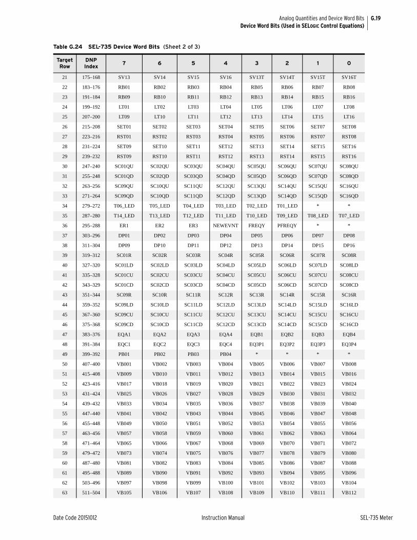
G.19
Date Code 20151012 Instruction Manual SEL-735 Meter
Analog Quantities and Device Word BitsDevice Word Bits (Used in SELOGIC Control Equations)
21 175–168 SV13 SV14 SV15 SV16 SV13T SV14T SV15T SV16T
22 183–176 RB01 RB02 RB03 RB04 RB05 RB06 RB07 RB08
23 191–184 RB09 RB10 RB11 RB12 RB13 RB14 RB15 RB16
24 199–192 LT01 LT02 LT03 LT04 LT05 LT06 LT07 LT08
25 207–200 LT09 LT10 LT11 LT12 LT13 LT14 LT15 LT16
26 215–208 SET01 SET02 SET03 SET04 SET05 SET06 SET07 SET08
27 223–216 RST01 RST02 RST03 RST04 RST05 RST06 RST07 RST08
28 231–224 SET09 SET10 SET11 SET12 SET13 SET14 SET15 SET16
29 239–232 RST09 RST10 RST11 RST12 RST13 RST14 RST15 RST16
30 247–240 SC01QU SC02QU SC03QU SC04QU SC05QU SC06QU SC07QU SC08QU
31 255–248 SC01QD SC02QD SC03QD SC04QD SC05QD SC06QD SC07QD SC08QD
32 263–256 SC09QU SC10QU SC11QU SC12QU SC13QU SC14QU SC15QU SC16QU
33 271–264 SC09QD SC10QD SC11QD SC12QD SC13QD SC14QD SC15QD SC16QD
34 279–272 T06_LED T05_LED T04_LED T03_LED T02_LED T01_LED * *
35 287–280 T14_LED T13_LED T12_LED T11_LED T10_LED T09_LED T08_LED T07_LED
36 295–288 ER1 ER2 ER3 NEWEVNT FREQY PFREQY * *
37 303–296 DP01 DP02 DP03 DP04 DP05 DP06 DP07 DP08
38 311–304 DP09 DP10 DP11 DP12 DP13 DP14 DP15 DP16
39 319–312 SC01R SC02R SC03R SC04R SC05R SC06R SC07R SC08R
40 327–320 SC01LD SC02LD SC03LD SC04LD SC05LD SC06LD SC07LD SC08LD
41 335–328 SC01CU SC02CU SC03CU SC04CU SC05CU SC06CU SC07CU SC08CU
42 343–329 SC01CD SC02CD SC03CD SC04CD SC05CD SC06CD SC07CD SC08CD
43 351–344 SC09R SC10R SC11R SC12R SC13R SC14R SC15R SC16R
44 359–352 SC09LD SC10LD SC11LD SC12LD SC13LD SC14LD SC15LD SC16LD
45 367–360 SC09CU SC10CU SC11CU SC12CU SC13CU SC14CU SC15CU SC16CU
46 375–368 SC09CD SC10CD SC11CD SC12CD SC13CD SC14CD SC15CD SC16CD
47 383–376 EQA1 EQA2 EQA3 EQA4 EQB1 EQB2 EQB3 EQB4
48 391–384 EQC1 EQC2 EQC3 EQC4 EQ3P1 EQ3P2 EQ3P3 EQ3P4
49 399–392 PB01 PB02 PB03 PB04 * * * *
50 407–400 VB001 VB002 VB003 VB004 VB005 VB006 VB007 VB008
51 415–408 VB009 VB010 VB011 VB012 VB013 VB014 VB015 VB016
52 423–416 VB017 VB018 VB019 VB020 VB021 VB022 VB023 VB024
53 431–424 VB025 VB026 VB027 VB028 VB029 VB030 VB031 VB032
54 439–432 VB033 VB034 VB035 VB036 VB037 VB038 VB039 VB040
55 447–440 VB041 VB042 VB043 VB044 VB045 VB046 VB047 VB048
56 455–448 VB049 VB050 VB051 VB052 VB053 VB054 VB055 VB056
57 463–456 VB057 VB058 VB059 VB060 VB061 VB062 VB063 VB064
58 471–464 VB065 VB066 VB067 VB068 VB069 VB070 VB071 VB072
59 479–472 VB073 VB074 VB075 VB076 VB077 VB078 VB079 VB080
60 487–480 VB081 VB082 VB083 VB084 VB085 VB086 VB087 VB088
61 495–488 VB089 VB090 VB091 VB092 VB093 VB094 VB095 VB096
62 503–496 VB097 VB098 VB099 VB100 VB101 VB102 VB103 VB104
63 511–504 VB105 VB106 VB107 VB108 VB109 VB110 VB111 VB112
Table G.24 SEL-735 Device Word Bits (Sheet 2 of 3)
Target Row
DNP Index
7 6 5 4 3 2 1 0

G.20
SEL-735 Meter Instruction Manual Date Code 20151012
Analog Quantities and Device Word BitsDevice Word Bits (Used in SELOGIC Control Equations)
64 519–512 VB113 VB114 VB115 VB116 VB117 VB118 VB119 VB120
65 527–520 VB121 VB122 VB123 VB124 VB10925 VB126 VB127 VB128
66 535–528 * * * PMTRIG TREA4 TREA3 TREA2 TREA1
67 543–536 TQUAL8 TQUAL4 TQUAL2 TQUAL1 * * * *
68 551–544 TS10SEC TS1MIN TS10MIN TS2HR TSDEM * * TIMESET
69 559–552 TSLDP1 TSLDP2 TSLDP3 TSLDP4 TSLDP5 TSLDP6 TSLDP7 TSLDP8
70 567–560 TSLDP9 TSLDP10 TSLDP11 TSLDP12 * * * *
71 575–568 * * * * * * * *
72 583–576 * * * * * * * *
a Optional feature.
Table G.24 SEL-735 Device Word Bits (Sheet 3 of 3)
Target Row
DNP Index
7 6 5 4 3 2 1 0

G.21
Date Code 20151012 Instruction Manual SEL-735 Meter
Analog Quantities and Device Word BitsDevice Word Bits (Used in SELOGIC Control Equations)
Table G.25 SEL-735 Device Word Bit Definitions (Sheet 1 of 16)
Row Bit Definition
0a 7 LED6 LED6 asserted
6 LED5 LED5 asserted
5 LED4 LED4 asserted
4 LED3 LED3 asserted
3 LED2 LED2 asserted
2 LED1 LED1 asserted
1 * Not used
0 ENABLE Meter enabled
1 7 FALARM Harmonic threshold alarm
6 HARM02 Second harmonic threshold
5 HARM03 Third harmonic threshold
4 HARM04 Fourth harmonic threshold
3 HARM05 Fifth harmonic threshold
2 HARM06 Sixth harmonic threshold
1 HARM07 Seventh harmonic threshold
0 HARM08 Eighth harmonic threshold
2 7 HARM09 Ninth harmonic threshold
6 HARM10 Tenth harmonic threshold
5 HARM11 Eleventh harmonic threshold
4 HARM12 Twelfth harmonic threshold
3 HARM13 Thirteenth harmonic threshold
2 HARM14 Fourteenth harmonic threshold
1 HARM15 Fifteenth harmonic threshold
0 RESET RESET bit asserted
3 7 SAGA A-phase voltage sag element
6 SAGB B-phase voltage sag element
5 SAGC C-phase voltage sag element
4 SAG3P Three-phase voltage sag element
3 SWA A-phase voltage swell element
2 SWB B-phase voltage swell element
1 SWC C-phase voltage sag element
0 SW3P Three-phase voltage swell element
4 7 SAGAB Phase-to-phase AB voltage sag element
6 SAGBC Phase-to-phase BC voltage sag element
5 SAGCA Phase-to-phase CA voltage sag element
4 ITIC_ND CBEMA/ITIC no damage region
3 SWAB Phase-to-phase AB voltage swell element
2 SWBC Phase-to-phase BC voltage swell element
1 SWCA Phase-to-phase CA voltage swell element
0 ITIC_PR CBEMA/ITIC prohibited region
5 7 INTA A-phase voltage interrupt element
6 INTB B-phase voltage interrupt element
5 INTC C-phase voltage interrupt element
4 INT3P Three-phase voltage interrupt element
3 INTAB Phase-to-phase AB voltage interrupt element
2 INTBC Phase-to-phase BC voltage interrupt element
1 INTCA Phase-to-phase CA voltage interrupt element
0 ITIC_SR CBEMA/ITIC safe region
6 7 ALTMODE Alternate display mode
6 EVNTCPT Event capture
5 PQALARM Power quality alarm
4 * Not used
3 RSTDEM Present demand value reset
2 EOIP End of Interval Pulse asserted (demand)
1 RSTPKDM Peak demand value reset
0 MATHERR Math error asserted for error in math variables
7 7 FLTBLK Fault block asserted
6 FAULT Fault bit asserted
5 DFAULT Delayed fault asserted
4 TEST Test mode bit asserted
3 IRIGOK IRIG-B input is active and used to set the meter time
2 SSI_EVE Detect SSI event within processing interval
1 MIU Modem in use
0 LOWBAT Low real-time clock battery warning
8 7 SESNCH TOU season change bit asserted
6 DSTCH DST change bit asserted
5 DSTP DST event pending
4 DST DST active
3 TIRIG Same as IRIGOK
2 RATECH Rate change bit asserted
1 TESTDB Test database command active
0 SETCH Settings change bit asserted
9 7 * Not used
6 * Not used
5 LPSECP Leap second pending (only set when connected to IRIG with IEEE C37.118 control bits)
Table G.25 SEL-735 Device Word Bit Definitions (Sheet 2 of 16)
Row Bit Definition

G.22
SEL-735 Meter Instruction Manual Date Code 20151012
Analog Quantities and Device Word BitsDevice Word Bits (Used in SELOGIC Control Equations)
4 LPSEC Leap second occurred (only set when connected to IRIG with IEEE C37.118 control bits)
3 TSNTPB Device time is based on SNTP, using SNTPBSIP
2 TSNTPP Device time is based on SNTP, using SNTPPSIP
1 TSOK Time synchronization OK. Asserts while time is based on an IRIG-B time source of sufficient accuracy for syn-chrophasor measurement.
0 PMDOK PMU (synchrophasor) data OK
10 7 OUT101 Output contact OUT101 asserted
6 OUT102 Output contact OUT102 asserted
5 OUT103 Output contact OUT103 asserted
4 OUT401b Output contact OUT401 asserted
3 OUT402b Output contact OUT402 asserted
2 OUT403b Output contact OUT403 asserted
1 OUT404b Output contact OUT404 asserted
0 SALARM Software alarm asserted
11 7 IN101 Optoisolated input IN101 asserted
6 IN102 Optoisolated input IN102 asserted
5 IN401b Optoisolated input IN401 asserted
4 IN402b Optoisolated input IN402 asserted
3 IN403b Optoisolated input IN403 asserted
2 IN404b Optoisolated input IN404 asserted
1 * Not used
0 HALARM Hardware alarm
12 7 KYZD1 KYZ pulse number 1
6 KYZD2 KYZ pulse number 2
5 KYZD3 KYZ pulse number 3
4 KYZD4 KYZ pulse number 4
3 KYZDT KYZ pulse test
2 RSTENGY Energy registers reset
1 PREDAL Predictive demand alarm
0 PPOWER Device sourcing +5V on an EIA-232 port
13 7 RMB8A Channel A, received bit 8
6 RMB7A Channel A, received bit 7
5 RMB6A Channel A, received bit 6
4 RMB5A Channel A, received bit 5
3 RMB4A Channel A, received bit 4
2 RMB3A Channel A, received bit 3
Table G.25 SEL-735 Device Word Bit Definitions (Sheet 3 of 16)
Row Bit Definition
1 RMB2A Channel A, received bit 2
0 RMB1A Channel A, received bit 1
14 7 TMB8A Channel A, transmit bit 8
6 TMB7A Channel A, transmit bit 7
5 TMB6A Channel A, transmit bit 6
4 TMB5A Channel A, transmit bit 5
3 TMB4A Channel A, transmit bit 4
2 TMB3A Channel A, transmit bit 3
1 TMB2A Channel A, transmit bit 2
0 TMB1A Channel A, transmit bit 1
15 7 RMB8B Channel B, received bit 8
6 RMB7B Channel B, received bit 7
5 RMB6B Channel B, received bit 6
4 RMB5B Channel B, received bit 5
3 RMB4B Channel B, received bit 4
2 RMB3B Channel B, received bit 3
1 RMB2B Channel B, received bit 2
0 RMB1B Channel B, received bit 1
16 7 TMB8B Channel B, transmit bit 8
6 TMB7B Channel B, transmit bit 7
5 TMB6B Channel B, transmit bit 6
4 TMB5B Channel B, transmit bit 5
3 TMB4B Channel B, transmit bit 4
2 TMB3B Channel B, transmit bit 3
1 TMB2B Channel B, transmit bit 2
0 TMB1B Channel B, transmit bit 1
17 7 LBOKB Channel B, looped back ok
6 CBADB Channel B, channel unavailability over threshold
5 RBADB Channel B, outage duration over threshold
4 ROKB Channel B, received data ok
3 LBOKA Channel A, looped back ok
2 CBADA Channel A, channel unavailability over threshold
1 RBADA Channel A, outage duration over threshold
0 ROKA Channel A, received data ok
18 7 SV01 SELOGIC control equation variable timer input SV1 asserted
6 SV02 SELOGIC control equation variable timer input SV2 asserted
Table G.25 SEL-735 Device Word Bit Definitions (Sheet 4 of 16)
Row Bit Definition

G.23
Date Code 20151012 Instruction Manual SEL-735 Meter
Analog Quantities and Device Word BitsDevice Word Bits (Used in SELOGIC Control Equations)
5 SV03 SELOGIC control equation variable timer input SV3 asserted
4 SV04 SELOGIC control equation variable timer input SV4 asserted
3 SV01T SELOGIC control equation variable timer output SV1T asserted
2 SV02T SELOGIC control equation variable timer output SV2T asserted
1 SV03T SELOGIC control equation variable timer output SV3T asserted
0 SV04T SELOGIC control equation variable timer output SV4T asserted
19 7 SV05 SELOGIC control equation variable timer input SV5 asserted
6 SV06 SELOGIC control equation variable timer input SV6 asserted
5 SV07 SELOGIC control equation variable timer input SV7 asserted
4 SV08 SELOGIC control equation variable timer input SV8 asserted
3 SV05T SELOGIC control equation variable timer output SV5T asserted
2 SV06T SELOGIC control equation variable timer output SV6T asserted
1 SV07T SELOGIC control equation variable timer output SV7T asserted
0 SV08T SELOGIC control equation variable timer output SV8T asserted
20 7 SV09 SELOGIC control equation variable timer input SV9 asserted
6 SV10 SELOGIC control equation variable timer input SV10 asserted
5 SV11 SELOGIC control equation variable timer input SV11 asserted
4 SV12 SELOGIC control equation variable timer input SV12 asserted
3 SV09T SELOGIC control equation variable timer output SV9T asserted
2 SV10T SELOGIC control equation variable timer output SV10T asserted
1 SV11T SELOGIC control equation variable timer output SV11T asserted
0 SV12T SELOGIC control equation variable timer output SV12T asserted
21 7 SV13 SELOGIC control equation variable timer input SV13 asserted
6 SV14 SELOGIC control equation variable timer input SV14 asserted
Table G.25 SEL-735 Device Word Bit Definitions (Sheet 5 of 16)
Row Bit Definition
5 SV15 SELOGIC control equation variable timer input SV15 asserted
4 SV16 SELOGIC control equation variable timer input SV16 asserted
3 SV13T SELOGIC control equation variable timer output SV13T asserted
2 SV14T SELOGIC control equation variable timer output SV14T asserted
1 SV15T SELOGIC control equation variable timer output SV15T asserted
0 SV16T SELOGIC control equation variable timer output SV16T asserted
22 7 RB01 Remote bit 1 asserted
6 RB02 Remote bit 2 asserted
5 RB03 Remote bit 3 asserted
4 RB04 Remote bit 4 asserted
3 RB05 Remote bit 5 asserted
2 RB06 Remote bit 6 asserted
1 RB07 Remote bit 7 asserted
0 RB08 Remote bit 8 asserted
23 7 RB09 Remote bit 9 asserted
6 RB10 Remote bit 10 asserted
5 RB11 Remote bit 11 asserted
4 RB12 Remote bit 12 asserted
3 RB13 Remote bit 13 asserted
2 RB14 Remote bit 14 asserted
1 RB15 Remote bit 15 asserted
0 RB16 Remote bit 16 asserted
24 7 LT01 Latch bit 1 asserted
6 LT02 Latch bit 2 asserted
5 LT03 Latch bit 3 asserted
4 LT04 Latch bit 4 asserted
3 LT05 Latch bit 5 asserted
2 LT06 Latch bit 6 asserted
1 LT07 Latch bit 7 asserted
0 LT08 Latch bit 8 asserted
25 7 LT09 Latch bit 9 asserted
6 LT10 Latch bit 10 asserted
5 LT11 Latch bit 11 asserted
4 LT12 Latch bit 12 asserted
3 LT13 Latch bit 13 asserted
2 LT14 Latch bit 14 asserted
Table G.25 SEL-735 Device Word Bit Definitions (Sheet 6 of 16)
Row Bit Definition

G.24
SEL-735 Meter Instruction Manual Date Code 20151012
Analog Quantities and Device Word BitsDevice Word Bits (Used in SELOGIC Control Equations)
1 LT15 Latch bit 15 asserted
0 LT16 Latch bit 16 asserted
26 7 SET01 Latch bit 1 set asserted
6 SET02 Latch bit 2 set asserted
5 SET03 Latch bit 3 set asserted
4 SET04 Latch bit 4 set asserted
3 SET05 Latch bit 5 set asserted
2 SET06 Latch bit 6 set asserted
1 SET07 Latch bit 7 set asserted
0 SET08 Latch bit 8 set asserted
27 7 RST01 Latch bit 1 reset asserted
6 RST02 Latch bit 2 reset asserted
5 RST03 Latch bit 3 reset asserted
4 RST04 Latch bit 4 reset asserted
3 RST05 Latch bit 5 reset asserted
2 RST06 Latch bit 6 reset asserted
1 RST07 Latch bit 7 reset asserted
0 RST08 Latch bit 8 reset asserted
28 7 SET09 Latch bit 9 set asserted
6 SET10 Latch bit 10 set asserted
5 SET11 Latch bit 11 set asserted
4 SET12 Latch bit 12 set asserted
3 SET13 Latch bit 13 set asserted
2 SET14 Latch bit 14 set asserted
1 SET15 Latch bit 15 set asserted
0 SET16 Latch bit 16 set asserted
29 7 RST09 Latch bit 9 reset asserted
6 RST10 Latch bit 10 reset asserted
5 RST11 Latch bit 11 reset asserted
4 RST12 Latch bit 12 reset asserted
3 RST13 Latch bit 13 reset asserted
2 RST14 Latch bit 14 reset asserted
1 RST15 Latch bit 15 reset asserted
0 RST16 Latch bit 16 reset asserted
30 7 SC01QU SELOGIC counter 1 up asserted
6 SC02QU SELOGIC counter 2 up asserted
5 SC03QU SELOGIC counter 3 up asserted
4 SC04QU SELOGIC counter 4 up asserted
3 SC05QU SELOGIC counter 5 up asserted
2 SC06QU SELOGIC counter 6 up asserted
Table G.25 SEL-735 Device Word Bit Definitions (Sheet 7 of 16)
Row Bit Definition
1 SC07QU SELOGIC counter 7 up asserted
0 SC08QU SELOGIC counter 8 up asserted
31 7 SC01QD SELOGIC counter 1 down asserted
6 SC02QD SELOGIC counter 2 down asserted
5 SC03QD SELOGIC counter 3 down asserted
4 SC04QD SELOGIC counter 4 down asserted
3 SC05QD SELOGIC counter 5 down asserted
2 SC06QD SELOGIC counter 6 down asserted
1 SC07QD SELOGIC counter 7 down asserted
0 SC08QD SELOGIC counter 8 down asserted
32 7 SC09QU SELOGIC counter 9 up asserted
6 SC10QU SELOGIC counter 10 up asserted
5 SC11QU SELOGIC counter 11 up asserted
4 SC12QU SELOGIC counter 12 up asserted
3 SC13QU SELOGIC counter 13 up asserted
2 SC14QU SELOGIC counter 14 up asserted
1 SC15QU SELOGIC counter 15 up asserted
0 SC16QU SELOGIC counter 16 up asserted
33 7 SC09QD SELOGIC counter 9 down asserted
6 SC10QD SELOGIC counter 10 down asserted
5 SC11QD SELOGIC counter 11 down asserted
4 SC12QD SELOGIC counter 12 down asserted
3 SC13QD SELOGIC counter 13 down asserted
2 SC14QD SELOGIC counter 14 down asserted
1 SC15QD SELOGIC counter 15 down asserted
0 SC16QD SELOGIC counter 16 down asserted
34 7 T06_LED LED 06 asserted
6 T05_LED LED 05 asserted
5 T04_LED LED 04 asserted
4 T03_LED LED 03 asserted
3 T02_LED LED 02 asserted
2 T01_LED LED 01 asserted
1 * Not used
0 * Not used
35 7 T14_LED LED 14 asserted
6 T13_LED LED 13 asserted
5 T12_LED LED 12 asserted
4 T11_LED LED 11 asserted
3 T10_LED LED 10 asserted
2 T09_LED LED 09 asserted
Table G.25 SEL-735 Device Word Bit Definitions (Sheet 8 of 16)
Row Bit Definition

G.25
Date Code 20151012 Instruction Manual SEL-735 Meter
Analog Quantities and Device Word BitsDevice Word Bits (Used in SELOGIC Control Equations)
1 T08_LED LED 08 asserted
0 T07_LED LED 07 asserted
36 7 ER1 Event report equation 1 asserted
6 ER2 Event report equation 2 asserted
5 ER3 Event report equation 3 asserted
4 NEWEVNT Asserts when a new event is triggered
3 FREQY FREQ is valid
2 PFREQY FREQ_PQ is valid
1 * Not used
0 * Not used
37 7 DP01 Display point 01 asserted
6 DP02 Display point 02 asserted
5 DP03 Display point 03 asserted
4 DP04 Display point 04 asserted
3 DP05 Display point 05 asserted
2 DP06 Display point 06 asserted
1 DP07 Display point 07 asserted
0 DP08 Display point 08 asserted
38 7 DP09 Display point 09 asserted
6 DP10 Display point 10 asserted
5 DP11 Display point 11 asserted
4 DP12 Display point 12 asserted
3 DP13 Display point 13 asserted
2 DP14 Display point 14 asserted
1 DP15 Display point 15 asserted
0 DP16 Display point 16 asserted
39 7 SC01R SELOGIC Counter 01, counter reset
6 SC02R SELOGIC Counter 02, counter reset
5 SC03R SELOGIC Counter 03, counter reset
4 SC04R SELOGIC Counter 04, counter reset
3 SC05R SELOGIC Counter 05, counter reset
2 SC06R SELOGIC Counter 06, counter reset
1 SC07R SELOGIC Counter 07, counter reset
0 SC08R SELOGIC Counter 08, counter reset
40 7 SC01LD SELOGIC Counter 01, load preset value
6 SC02LD SELOGIC Counter 02, load preset value
5 SC03LD SELOGIC Counter 03, load preset value
4 SC04LD SELOGIC Counter 04, load preset value
3 SC05LD SELOGIC Counter 05, load preset value
2 SC06LD SELOGIC Counter 06, load preset value
Table G.25 SEL-735 Device Word Bit Definitions (Sheet 9 of 16)
Row Bit Definition
1 SC07LD SELOGIC Counter 07, load preset value
0 SC08LD SELOGIC Counter 08, load preset value
41 7 SC01CU SELOGIC Counter 01, count up
6 SC02CU SELOGIC Counter 02, count up
5 SC03CU SELOGIC Counter 03, count up
4 SC04CU SELOGIC Counter 04, count up
3 SC05CU SELOGIC Counter 05, count up
2 SC06CU SELOGIC Counter 06, count up
1 SC07CU SELOGIC Counter 07, count up
0 SC08CU SELOGIC Counter 08, count up
42 7 SC01CD SELOGIC Counter 01, count down
6 SC02CD SELOGIC Counter 02, count down
5 SC03CD SELOGIC Counter 03, count down
4 SC04CD SELOGIC Counter 04, count down
3 SC05CD SELOGIC Counter 05, count down
2 SC06CD SELOGIC Counter 06, count down
1 SC07CD SELOGIC Counter 07, count down
0 SC08CD SELOGIC Counter 08, count down
43 7 SC09R SELOGIC Counter 09, counter reset
6 SC10R SELOGIC Counter 10, counter reset
5 SC11R SELOGIC Counter 11, counter reset
4 SC12R SELOGIC Counter 12, counter reset
3 SC13R SELOGIC Counter 13, counter reset
2 SC14R SELOGIC Counter 14, counter reset
1 SC15R SELOGIC Counter 15, counter reset
0 SC16R SELOGIC Counter 16, counter reset
44 7 SC09LD SELOGIC Counter 09, load preset value
6 SC10LD SELOGIC Counter 10, load preset value
5 SC11LD SELOGIC Counter 11, load preset value
4 SC12LD SELOGIC Counter 12, load preset value
3 SC13LD SELOGIC Counter 13, load preset value
2 SC14LD SELOGIC Counter 14, load preset value
1 SC15LD SELOGIC Counter 15, load preset value
0 SC16LD SELOGIC Counter 16, load preset value
45 7 SC09CU SELOGIC Counter 09, count up
6 SC10CU SELOGIC Counter 10, count up
5 SC11CU SELOGIC Counter 11, count up
4 SC12CU SELOGIC Counter 12, count up
3 SC13CU SELOGIC Counter 13, count up
2 SC14CU SELOGIC Counter 14, count up
Table G.25 SEL-735 Device Word Bit Definitions (Sheet 10 of 16)
Row Bit Definition

G.26
SEL-735 Meter Instruction Manual Date Code 20151012
Analog Quantities and Device Word BitsDevice Word Bits (Used in SELOGIC Control Equations)
1 SC15CU SELOGIC Counter 15, count up
0 SC16CU SELOGIC Counter 16, count up
46 7 SC09CD SELOGIC Counter 09, count down
6 SC10CD SELOGIC Counter 10, count down
5 SC11CD SELOGIC Counter 11, count down
4 SC12CD SELOGIC Counter 12, count down
3 SC13CD SELOGIC Counter 13, count down
2 SC14CD SELOGIC Counter 14, count down
1 SC15CD SELOGIC Counter 15, count down
0 SC16CD SELOGIC Counter 16, count down
47 7 EQA1 VARs, A-phase, Quadrant I
6 EQA2 VARs, A-phase, Quadrant II
5 EQA3 VARs, A-phase, Quadrant III
4 EQA4 VARs, A-phase, Quadrant IV
3 EQB1 VARs, B-phase, Quadrant I
2 EQB2 VARs, B-phase, Quadrant II
1 EQB3 VARs, B-phase, Quadrant III
0 EQB4 VARs, B-phase, Quadrant IV
48 7 EQC1 VARs, C-phase, Quadrant I
6 EQC2 VARs, C-phase, Quadrant II
5 EQC3 VARs, C-phase, Quadrant III
4 EQC4 VARs, C-phase, Quadrant IV
3 EQ3P1 VARs, 3-phase, Quadrant I
2 EQ3P2 VARs, 3-phase, Quadrant II
1 EQ3P3 VARs, 3-phase, Quadrant III
0 EQ3P4 VARs, 3-phase, Quadrant IV
49 7 PB01 Pushbutton 1 bit asserted
6 PB02 Pushbutton 2 bit asserted
5 PB03 Pushbutton 3 bit asserted
4 PB04 Pushbutton 4 bit asserted
3 * Not used
2 * Not used
1 * Not used
0 * Not used
50 7 VB001 Virtual Bit
6 VB002 Virtual Bit
5 VB003 Virtual Bit
4 VB004 Virtual Bit
3 VB005 Virtual Bit
2 VB006 Virtual Bit
Table G.25 SEL-735 Device Word Bit Definitions (Sheet 11 of 16)
Row Bit Definition
1 VB007 Virtual Bit
0 VB008 Virtual Bit
51 7 VB009 Virtual Bit
6 VB010 Virtual Bit
5 VB011 Virtual Bit
4 VB012 Virtual Bit
3 VB013 Virtual Bit
2 VB014 Virtual Bit
1 VB015 Virtual Bit
0 VB016 Virtual Bit
52 7 VB017 Virtual Bit
6 VB018 Virtual Bit
5 VB019 Virtual Bit
4 VB020 Virtual Bit
3 VB021 Virtual Bit
2 VB022 Virtual Bit
1 VB023 Virtual Bit
0 VB024 Virtual Bit
53 7 VB025 Virtual Bit
6 VB026 Virtual Bit
5 VB027 Virtual Bit
4 VB028 Virtual Bit
3 VB029 Virtual Bit
2 VB030 Virtual Bit
1 VB031 Virtual Bit
0 VB032 Virtual Bit
54 7 VB033 Virtual Bit
6 VB034 Virtual Bit
5 VB035 Virtual Bit
4 VB036 Virtual Bit
3 VB037 Virtual Bit
2 VB038 Virtual Bit
1 VB039 Virtual Bit
0 VB040 Virtual Bit
55 7 VB041 Virtual Bit
6 VB042 Virtual Bit
5 VB043 Virtual Bit
4 VB044 Virtual Bit
3 VB045 Virtual Bit
2 VB046 Virtual Bit
Table G.25 SEL-735 Device Word Bit Definitions (Sheet 12 of 16)
Row Bit Definition

G.27
Date Code 20151012 Instruction Manual SEL-735 Meter
Analog Quantities and Device Word BitsDevice Word Bits (Used in SELOGIC Control Equations)
1 VB047 Virtual Bit
0 VB048 Virtual Bit
56 7 VB049 Virtual Bit
6 VB050 Virtual Bit
5 VB051 Virtual Bit
4 VB052 Virtual Bit
3 VB053 Virtual Bit
2 VB054 Virtual Bit
1 VB055 Virtual Bit
0 VB056 Virtual Bit
57 7 VB057 Virtual Bit
6 VB058 Virtual Bit
5 VB059 Virtual Bit
4 VB060 Virtual Bit
3 VB061 Virtual Bit
2 VB062 Virtual Bit
1 VB063 Virtual Bit
0 VB064 Virtual Bit
58 7 VB065 Virtual Bit
6 VB066 Virtual Bit
5 VB067 Virtual Bit
4 VB068 Virtual Bit
3 VB069 Virtual Bit
2 VB070 Virtual Bit
1 VB071 Virtual Bit
0 VB072 Virtual Bit
59 7 VB073 Virtual Bit
6 VB074 Virtual Bit
5 VB075 Virtual Bit
4 VB076 Virtual Bit
3 VB077 Virtual Bit
2 VB078 Virtual Bit
1 VB079 Virtual Bit
0 VB080 Virtual Bit
60 7 VB081 Virtual Bit
6 VB082 Virtual Bit
5 VB083 Virtual Bit
4 VB084 Virtual Bit
3 VB085 Virtual Bit
2 VB086 Virtual Bit
Table G.25 SEL-735 Device Word Bit Definitions (Sheet 13 of 16)
Row Bit Definition
1 VB087 Virtual Bit
0 VB088 Virtual Bit
61 7 VB089 Virtual Bit
6 VB090 Virtual Bit
5 VB091 Virtual Bit
4 VB092 Virtual Bit
3 VB093 Virtual Bit
2 VB094 Virtual Bit
1 VB095 Virtual Bit
0 VB096 Virtual Bit
62 7 VB097 Virtual Bit
6 VB098 Virtual Bit
5 VB099 Virtual Bit
4 VB100 Virtual Bit
3 VB101 Virtual Bit
2 VB102 Virtual Bit
1 VB103 Virtual Bit
0 VB104 Virtual Bit
63 7 VB105 Virtual Bit
6 VB106 Virtual Bit
5 VB107 Virtual Bit
4 VB108 Virtual Bit
3 VB109 Virtual Bit
2 VB110 Virtual Bit
1 VB111 Virtual Bit
0 VB112 Virtual Bit
64 7 VB113 Virtual Bit
6 VB114 Virtual Bit
5 VB115 Virtual Bit
4 VB116 Virtual Bit
3 VB117 Virtual Bit
2 VB118 Virtual Bit
1 VB119 Virtual Bit
0 VB120 Virtual Bit
65 7 VB121 Virtual Bit
6 VB122 Virtual Bit
5 VB123 Virtual Bit
4 VB124 Virtual Bit
3 VB125 Virtual Bit
2 VB126 Virtual Bit
Table G.25 SEL-735 Device Word Bit Definitions (Sheet 14 of 16)
Row Bit Definition

G.28
SEL-735 Meter Instruction Manual Date Code 20151012
Analog Quantities and Device Word BitsDevice Word Bits (Used in SELOGIC Control Equations)
1 VB127 Virtual Bit
0 VB128 Virtual Bit
66 7 * Not used
6 * Not used
5 * Not used
4 PMTRIG Synchrophasor PMU Trigger
3 TREA4 Synchrophasor PMU Trigger Reason Bit 4
2 TREA3 Synchrophasor PMU TriggerReason Bit 3
1 TREA2 Synchrophasor PMU Trigger Reason Bit 2
0 TREA1 Synchrophasor PMU Trigger Reason Bit 1
67 7 TQUAL8 IRIG Time Quality Bit 4
6 TQUAL4 IRIG Time Quality Bit 3
5 TQUAL2 IRIG Time Quality Bit 2
4 TQUAL1 IRIG Time Quality Bit 1
3 * Not used
2 * Not used
1 * Not used
0 * Not used
68 7 TS10SEC Timeset greater than TIME_CHG in presently published 10 second interval
6 TS1MIN Timeset greater than TIME_CHG in presently published 1 minute interval
5 TS10MIN Timeset greater than TIME_CHG in presently published 10 minute interval
4 TS2HR Timeset greater than TIME_CHG in presently published 2 hour interval
3 TSDEM Timeset greater than TIME_CHG in presently published demand interval
2 * Not used
1 * Not used
0 TIMESET Timeset from secondary time source
69 7 TSLDP1 Timeset greater than TIME_CHG in last LDP1 interval
6 TSLDP2 Timeset greater than TIME_CHG in last LDP2 interval
5 TSLDP3 Timeset greater than TIME_CHG in last LDP3 interval
4 TSLDP4 Timeset greater than TIME_CHG in last LDP4 interval
3 TSLDP5 Timeset greater than TIME_CHG in last LDP5 interval
Table G.25 SEL-735 Device Word Bit Definitions (Sheet 15 of 16)
Row Bit Definition
2 TSLDP6 Timeset greater than TIME_CHG in last LDP6 interval
1 TSLDP7 Timeset greater than TIME_CHG in last LDP7 interval
0 TSLDP8 Timeset greater than TIME_CHG in last LDP8 interval
70 7 TSLDP9 Timeset greater than TIME_CHG in last LDP9 interval
6 TSLDP10 Timeset greater than TIME_CHG in last LDP10 interval
5 TSLDP11 Timeset greater than TIME_CHG in last LDP11 interval
4 TSLDP12 Timeset greater than TIME_CHG in last LDP12 interval
3 * Not used
2 * Not used
1 * Not used
0 * Not used
71 7 * Not used
6 * Not used
5 * Not used
4 * Not used
3 * Not used
2 * Not used
1 * Not used
0 * Not used
72 7 * Not used
6 * Not used
5 * Not used
4 * Not used
3 * Not used
2 * Not used
1 * Not used
0 * Not used
a Row 0 Device Word Bits are not available via the Front-Panel HMI Targets menu, SELOGIC, or Report Settings.
b Optional feature.
Table G.25 SEL-735 Device Word Bit Definitions (Sheet 16 of 16)
Row Bit Definition

Date Code 20151012 Instruction Manual SEL-735 Meter
Appendix HIEC 61850 Communications
FeaturesThe SEL-735 Power Quality and Revenue Meter supports the following features using Ethernet and IEC 61850:
➤ SCADA—Connect as many as six simultaneous IEC 61850 MMS client sessions. The SEL-735 also supports as many as six buffered and six unbuffered report control blocks. See Table H.14 for Logical Node mapping that enables SCADA control via a Manufacturing Messaging Specification (MMS) browser. Controls support the direct control with normal security, direct control with enhanced security, and select-before-operate (SBO) with enhanced security control models.
➤ Peer-to-Peer Real-Time Status and Control—Use GOOSE with as many as 24 incoming (receive) and 8 outgoing (transmit) messages. Virtual bits (VB001–VB128) and Remote Analogs (RA00–RA31) can be mapped from incoming GOOSE messages.
➤ Configuration—Use FTP client software or ACSELERATOR
Architect® SEL-5032 Software to transfer the Substation Configuration Language (SCL) Configured IED Description (CID) file to the meter.
➤ Commissioning and Troubleshooting—Use software such as MMS Object Explorer and AX-S4 MMS from Sisco, Inc., to browse the meter logical nodes and verify functionality.
➤ IEC 61850 Standard—IEC 61850 Standard, Edition 1 is supported.
This section presents the information you need to use the IEC 61850 features of the SEL-735:
➤ Introduction to IEC 61850
➤ IEC 61850 Operation on page H.3
➤ IEC 61850 Configuration on page H.13
➤ Logical Nodes on page H.17
NOTE: The SEL-735 supports one CID file, which should be transferred only if a change in the meter configuration is required. If an invalid CID file is transferred, the meter will no longer have a valid IEC 61850 configuration, and the protocol will stop operating. To restart protocol operation, a valid CID must be transferred to the meter.
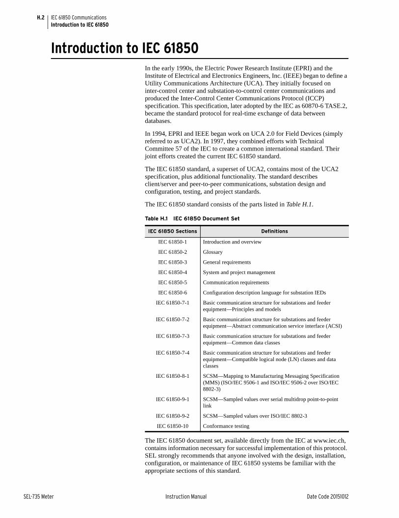
H.2
SEL-735 Meter Instruction Manual Date Code 20151012
IEC 61850 CommunicationsIntroduction to IEC 61850
Introduction to IEC 61850In the early 1990s, the Electric Power Research Institute (EPRI) and the Institute of Electrical and Electronics Engineers, Inc. (IEEE) began to define a Utility Communications Architecture (UCA). They initially focused on inter-control center and substation-to-control center communications and produced the Inter-Control Center Communications Protocol (ICCP) specification. This specification, later adopted by the IEC as 60870-6 TASE.2, became the standard protocol for real-time exchange of data between databases.
In 1994, EPRI and IEEE began work on UCA 2.0 for Field Devices (simply referred to as UCA2). In 1997, they combined efforts with Technical Committee 57 of the IEC to create a common international standard. Their joint efforts created the current IEC 61850 standard.
The IEC 61850 standard, a superset of UCA2, contains most of the UCA2 specification, plus additional functionality. The standard describes client/server and peer-to-peer communications, substation design and configuration, testing, and project standards.
The IEC 61850 standard consists of the parts listed in Table H.1.
The IEC 61850 document set, available directly from the IEC at www.iec.ch, contains information necessary for successful implementation of this protocol. SEL strongly recommends that anyone involved with the design, installation, configuration, or maintenance of IEC 61850 systems be familiar with the appropriate sections of this standard.
Table H.1 IEC 61850 Document Set
IEC 61850 Sections Definitions
IEC 61850-1 Introduction and overview
IEC 61850-2 Glossary
IEC 61850-3 General requirements
IEC 61850-4 System and project management
IEC 61850-5 Communication requirements
IEC 61850-6 Configuration description language for substation IEDs
IEC 61850-7-1 Basic communication structure for substations and feeder equipment—Principles and models
IEC 61850-7-2 Basic communication structure for substations and feeder equipment—Abstract communication service interface (ACSI)
IEC 61850-7-3 Basic communication structure for substations and feeder equipment—Common data classes
IEC 61850-7-4 Basic communication structure for substations and feeder equipment—Compatible logical node (LN) classes and data classes
IEC 61850-8-1 SCSM—Mapping to Manufacturing Messaging Specification (MMS) (ISO/IEC 9506-1 and ISO/IEC 9506-2 over ISO/IEC 8802-3)
IEC 61850-9-1 SCSM—Sampled values over serial multidrop point-to-point link
IEC 61850-9-2 SCSM—Sampled values over ISO/IEC 8802-3
IEC 61850-10 Conformance testing

H.3
Date Code 20151012 Instruction Manual SEL-735 Meter
IEC 61850 CommunicationsIEC 61850 Operation
IEC 61850 OperationEthernet Networking IEC 61850 and Ethernet networking model options are available when
ordering a new SEL-735 and may also be available as field upgrades to meters equipped with copper or fiber-optic Ethernet. In addition to IEC 61850, the meter provides support protocols and data exchange, including FTP and Telnet. Access the SEL-735 Port 1 settings to configure all of the Ethernet settings, including IEC 61850 enable settings.
The SEL-735 supports IEC 61850 services, including transport of Logical Node objects, over TCP/IP. The meter can coordinate a maximum of six concurrent IEC 61850 sessions.
Object Models The IEC 61850 standard relies heavily on the Abstract Communication Service Interface (ACSI) models to define a set of services and the responses to those services. In terms of network behavior, abstract modeling enables all IEDs to act identically. These abstract models are used to create objects (data items) and services that exist independently of any underlying protocols. These objects are in conformance with the common data class (CDC) specification IEC 61850-7-3, which describes the type and structure of each element within a logical node. CDCs for status, measurements, controllable analogs and statuses, and settings all have unique CDC attributes. Each CDC attribute belongs to a set of functional constraints that groups the attributes into specific categories such as status (ST), description (DC), and substituted value (SV). Functional constraints, CDCs, and CDC attributes are used as building blocks for defining Logical Nodes.
UCA2 used Generic Object Models for Substation and Feeder Equipment (GOMSFE) to present data from station IEDs as a series of objects called models or bricks. The IEC working group has incorporated GOMSFE concepts into the standard, with some modifications to terminology; one change was the renaming of bricks to logical nodes. Each logical node represents a group of data (controls, status, measurements, etc.) associated with a particular function. For example, the MMXU logical node (polyphase measurement unit) contains non-revenue grade measurement data and other points associated with three-phase fundamental quantity metering including voltages and currents. Each IED may contain many functions such as protection, metering, and control. Multiple logical nodes represent the functions in multifunction devices.
Logical nodes can be organized into logical devices that are similar to directories on a computer disk. As represented in the IEC 61850 network, each physical device can contain many logical devices and each logical device can contain many logical nodes. Many relays, meters, and other IEC 61850 devices contain one primary logical device where all models are organized.
IEC 61850 devices are capable of self-description. You do not need to refer to the specifications for the logical nodes, measurements, and other components to request data from another IEC 61850 device. IEC 61850 clients can request and display a list and description of the data available in an IEC 61850 server device. This process is similar to the autoconfiguration process used within SEL communications processors (SEL-2032 and SEL-2030). Simply run an MMS browser to query devices on an IEC 61850 network and discover what data are available. Self-description also permits extensions to both standard and custom data models. Instead of having to look up data in a profile stored in its database, an IEC 61850 client can simply query an IEC 61850 device and receive a description of all logical devices, logical nodes, and available data.

H.4
SEL-735 Meter Instruction Manual Date Code 20151012
IEC 61850 CommunicationsIEC 61850 Operation
Unlike other Supervisory Control and Data Acquisition (SCADA) protocols that present data as a list of addresses or indices, IEC 61850 presents data with descriptors in a composite notation made up of components. Table H.2 shows how the A-phase current expressed as MET$FUNDMMXU1$A$phsA$cVal$mag$f is broken down into its component parts. The Data Attribute is characterized (filtered) by a functional constraint (FC) property. The supported FCs are listed in Table H.3. The FC for the given example above is MX.
Data Mapping Device data are mapped to IEC 61850 Logical Nodes (LN) according to rules defined by SEL. Refer to IEC 61850-5:2003(E) and IEC 61850-7-4:2003(E) for the mandatory content and usage of these LNs. The SEL-735 logical nodes are grouped under Logical Devices for organization based on function. See Table H.4 for descriptions of the Logical Devices in an SEL-735. See Logical Nodes on page H.17 for a description of the LNs that make up these Logical Devices.
MMS Manufacturing Messaging Specification (MMS) provides services for the application-layer transfer of real-time data within a substation LAN. MMS was developed as a network independent data exchange protocol for industrial networks in the 1980s and standardized as ISO 9506.
In theory, you can map IEC 61850 to any protocol. However, it can become unwieldy and quite complicated to map objects and services to a protocol that only provides access to simple data points via registers or index numbers.
Table H.2 Example IEC 61850 Descriptor Components
Component Description
FUNDMMXU1 Logical Node Device fundamental quantities
A Data Object Phase amperes
phsA Sub-Data Object Phase A
.cVal Data Attribute Complex value
mag Sub-Data Object Magnitude
f Data Type Float32
Table H.3 Functional Constraints
FC Description
ST Status information
MX Measurements (analog values)
CO Control
CF Configuration
DC Description
EX Extended definition
Table H.4 SEL-735 Logical Devices
Logical Device Description
ANN Annunciator elements—alarms, status values, and logic elements
CFG Configuration elements—datasets and report control blocks
CON Control elements—remote bits
MET Metering or Measurement elements—currents, voltages, power, etc.

H.5
Date Code 20151012 Instruction Manual SEL-735 Meter
IEC 61850 CommunicationsIEC 61850 Operation
MMS supports complex named objects and flexible services that enable mapping to IEC 61850 in a straightforward manner. This was why the UCA users group used MMS for UCA from the start, and why the IEC chose to keep it for IEC 61850.
In the SEL-735, event files and reports can be read through MMS and settings can be written using MMS. See File Transfer Protocol (FTP) and MMS File Transfer on page 8.11.
If MMS authentication is enabled, the device will authenticate each MMS association by requiring the client to provide the password authentication parameter with a value that is equal to the 2AC password of the SEL-735.
➤ If the correct password authentication parameter value is not received, the device will return a not authenticated error code.
➤ If the correct password authentication parameter value is received, the device will give a successful association response. The device will allow access to all supported MMS services for that association.
GOOSE The Generic Object Oriented Substation Event (GOOSE) object within IEC 61850 is for high-speed control messaging. IEC 61850 GOOSE automatically broadcasts messages containing status, controls, and measured values onto the network for use by other devices. IEC 61850 GOOSE sends the message several times, increasing the likelihood that other devices receive the messages. GOOSE message publication is a persistent function. Once GOOSE is enabled, the IED will continuously publish GOOSE messages until they are disabled regardless of the contents. The publication process description indicates when and why the publication rate changes.
IEC 61850 GOOSE objects can quickly and conveniently transfer status, controls, and measured values between peers on an IEC 61850 network. Configure SEL devices to respond to GOOSE messages from other network devices with ACSELERATOR Architect. Also, configure outgoing GOOSE messages for SEL devices in ACSELERATOR Architect. See the ACSELERATOR Architect instruction manual or online help for more information.
Each IEC 61850 GOOSE sender includes a text identification string (GOOSE Control Block Reference), APP ID field, and an Ethernet multicast group address, in each outgoing message. Some devices that receive GOOSE messages use the text identification and multicast group to identify and filter incoming GOOSE messages. The parameters used to identify incoming GOOSE messages are configurable with ACSELERATOR Architect and multicast group to identify and filter incoming GOOSE messages.
Virtual bits (VB001–VB128) are control inputs that you can map to GOOSE receive messages using the ACSELERATOR Architect software. If you intend to use any SEL-735 virtual bits for controls, you must create SELOGIC® control equations to define these operations. The SEL-735 is capable of receiving and sending analog values via peer-to-peer GOOSE messages. Remote Analogs (RA001–RA128) are analog inputs that you can map to values from incoming GOOSE messages.
NOTE: After sending settings to the SEL-735 via MMS, read the err.txt file to see if any errors were encountered while applying the settings.

H.6
SEL-735 Meter Instruction Manual Date Code 20151012
IEC 61850 CommunicationsIEC 61850 Operation
File Services The File System supports FTP and MMS file transfer. The File System provides:
➤ A means for the device to transfer data as files.
➤ A hierarchal file structure for the device data.
See File Transfer Protocol (FTP) and MMS File Transfer on page 8.11 for more information about file services.
SCL Files Substation Configuration Language (SCL) is an XML-based configuration language used to support the exchange of database configuration data between different tools, which may come from different manufacturers. There are four types of SCL files:
➤ Intelligent Electronic Device (IED) Capability Description file (.ICD)
➤ System Specification Description (.SSD) file
➤ Substation Configuration Description file (.SCD)
➤ Configured IED Description file (.CID)
The ICD file describes the capabilities of an IED, including information on LN and GOOSE support. The SSD file describes the single-line diagram of the substation and the required LNs. The SCD file contains information on all IEDs, communications configuration data, and a substation description. The CID file, of which there may be several, describes a single instantiated IED within the project, and includes address information.
Datasets Datasets are configured using ACSELERATOR Architect® SEL-5032 Software and contain data attributes that represent real data values within the SEL-735 device. See Logical Nodes for the logical node tables that list the available data attributes for each logical node and the Device Word bit mapping for these data attributes. The list of datasets in Figure H.1 are the defaults for a SEL-735 device. Datasets 1 through 12 are preconfigured with common FCDAs to be used for reporting. These datasets can be configured to represent the desired data to be monitored.
Figure H.1 SEL-735 Datasets

H.7
Date Code 20151012 Instruction Manual SEL-735 Meter
IEC 61850 CommunicationsIEC 61850 Operation
Within ACSELERATOR Architect, IEC 61850 datasets have the following purposes:
➤ GOOSE: You can use predefined or edited datasets, or create new datasets for outgoing GOOSE transmission.
➤ Reports: Twelve predefined datasets (DSet01 to DSet12) correspond to the default six buffered and six unbuffered reports. Note that you cannot change the number (12) or type of reports (buffered or unbuffered) within ACSELERATOR Architect. However, you can alter the data attributes that a dataset contains and so define what data an IEC 61850 client receives with a report.
➤ MMS: You can use predefined or edited datasets, or you can create new datasets to be monitored by MMS clients.
Reports The SEL-735 implements the IEC 61850 reporting service as part of its server functionality. The reporting service includes the functionality necessary to configure, manage, and send IEC 61850 buffered and unbuffered reports as unsolicited data change reports, periodic integrity reports, or as the result of a general interrogation. See the IEC 61850 Standard, Part 7-1, Section 6.4.3.3, Part 7-2, Section 14, and Part 8-1, Section 17 for more details on the IEC 61850 reporting service.
A total of 12 predefined reports (6 buffered and 6 unbuffered) are supported. The predefined reports and the datasets assigned to each report are shown in Figure H.2 and are available by default via IEC 61850. The number of reports (12), the dataset assigned to each report, and the type of reports (buffered or unbuffered) cannot be changed. However, by using ACSELERATOR Architect software, you can reallocate data within each report dataset to present different data attributes for each report beyond the predefined datasets.
Figure H.2 SEL-735 Predefined Reports
Buffered and unbuffered report control blocks are supported in the report model as defined in IEC 61850-8-1:2004(E). There are 12 report control blocks (6 buffered and 6 unbuffered).
For each buffered report control block (BRCB), there can be just one client association (i.e., only one client can be associated to a BRCB at any given time). The client association occurs when the client enables the RptEna attribute of the BRCB. Once enabled, the associated client has exclusive
NOTE: Do not edit the dataset names used in reports. Changing or deleting any of those dataset names will cause a failure in generating the corresponding report.

H.8
SEL-735 Meter Instruction Manual Date Code 20151012
IEC 61850 CommunicationsIEC 61850 Operation
access to the BRCB until the connection is closed or the client disables the RptEna attribute. Once enabled, all unassociated clients have read only access to the BRCB and the associated client will be the only client that receives buffered report data. The BRCB parameters are shown in Table H.5.
Once a BRCB has been enabled, a report buffer is established. The buffer is sized to contain 10 complete reports with a size hard coded in the SEL-735 ICD file. However, in cases where the report dataset is smaller than the allowed maximum size, or when the encoded report does not include the entire dataset, as many as 200 reports may appear in the buffer. Reports are maintained in the buffer regardless of having been sent. This allows the client to retrieve reports that have already been sent by writing an EntryID prior to the current EntryID.
When a client sets the RptEna attribute of a BRCB to true, all new reports contained in the report buffer, starting from the buffer entry following the EntryID attribute specified in the BRCB until the most current buffered report, are sent. At this time, new reports will be sent as required by normal report processing. This behavior allows the client to write the last received EntryID to the BRCB before enabling the report in an attempt to retrieve all report entries that were lost during a lapse in the client association.
When insertion of a new report into a report buffer would cause the buffer size to be exceeded, the oldest entries in the buffer are discarded until the buffer size has been reduced sufficiently to allow the new report to be added to the buffer. If the reports removed from the buffer have not yet been sent to the client, a buffer overflow indication is set in the next report queued for transmission to indicate that reports have been lost. The buffer overflow indication is reported in the BufOvfl field of the report if the buffer overflow OptFld has been enabled in the BRCB.
Table H.5 Buffered Report Control Block Client Access
RCB AttributeUser Changeable (Report Disabled)
User Changeable (Report Enabled)
Default Values
RptId YES DSet01–DSet06
RptEna YES YES FALSE
OptFlds YES seqNum
timeStamp
dataSet
reasonCode
confRev
BufTm YES 500
TrgOps YES dchg
qchg
IntgPd YES 0
GI YESa b
a Exhibits a pulse behavior. Write a one to issue the command. Once command is accepted will return to zero. Always read as zero.
b When disabled, a GI will be processed and the report buffered if a buffer has been previously established. A buffer is established when the report is enabled for the first time.
YESa FALSE
PurgeBuf YESa FALSE
EntryId YES 0

H.9
Date Code 20151012 Instruction Manual SEL-735 Meter
IEC 61850 CommunicationsIEC 61850 Operation
The contents of a report buffer are deleted when a PurgeBuf is commanded by a client. As noted in the requirements for the BRCB, the PurgeBuf can only be commanded when the report is disabled. The buffer overflow indication shall be cleared when the client commands a PurgeBuf. Additionally, the buffered reports will be purged if any of the BRCB attributes RptID, DatSet, BufTm, TrgOps, or IntgPd are modified by the client while the report is disabled.
For each unbuffered control block (URCB), there can be as many as six client associations. The client association occurs when the client enables the RptEna attribute of the URCB. Once enabled, each client has independent access to its instance of the URCB and all associated clients receive unbuffered report data. The URCB parameters are shown in Table H.6.
The URCB Resv attribute is writable, however, the SEL-735 does not support reservations. Writing any field of the URCB causes the client to obtain their own instance of the URCB—in essence, acquiring a reservation.
The IEC 61850 standard defines the trigger options (TrgOps) of data change, quality change, and data update. These TrgOps allow reports to be filtered to report only changes associated with the selected TrgOps. Additionally, each of these TrgOps is only associated with or valid for certain data attributes. The valid TrgOps for any given data attribute is described in the Common Data Class (CDC) Descriptions contained within the IEC standard, Part 7-3.
When a client has enabled the RptEna attribute of a BRCB or an URCB, and any of the data change or quality change TrgOps are enabled within the same BRCB or URCB, the SEL-735 sends an unsolicited report to that client upon detecting a change on an FCDA with a reason corresponding to one of the enabled TrgOps. The unsolicited report contains only those FCDAs that have been detected to have changed for a reason corresponding to one of the enabled TrgOps.
When a client has enabled the RptEna attribute of a BRCB or an URCB, and that same client writes a non-zero value to the GI attribute of the BRCB or URCB, a report is sent to that client containing the current data for all FCDA within the report dataset.
Table H.6 Unbuffered Report Control Block Client Access
RCB AttributeUser Changeable (Report Disabled)
User Changeable (Report Enabled)
Default Values
RptId YES DSet07–DSet12
RptEna YES YES FALSE
Resv YES FALSE
OptFlds YES seqNum
timeStamp
dataSet
reasonCode
confRev
BufTm YES 250
TrgOps YES dchg
qchg
IntgPd YES 0
GI YESa
a Exhibits a pulse behavior. Write a one to issue the command. Once command is accepted will return to zero. Always read as zero.
FALSE
NOTE: The TrgOp data update is not supported by the SEL-735 device.

H.10
SEL-735 Meter Instruction Manual Date Code 20151012
IEC 61850 CommunicationsIEC 61850 Operation
When a client has enabled the RptEna attribute and the IntgPd TrgOp of a BRCB or an URCB, and the IntgPd attribute of the BRCB or URCB is set to a non-zero value, a report is sent to that client containing the current data for all FCDAs within the report dataset upon detecting an expiration of the IntgPd.
FCDA updates are serviced every 500 ms. The client can set the report control block (BRCB or URCB) IntgPd to any value greater than 500 ms with a resolution of 1 ms. However, the integrity report is only sent when the period has been detected as having expired. The new IntgPd will begin at the time that the current report is serviced.
BufTm timers are part of the report control block (BRCB and URCB). The purpose of the BufTm timers is to buffer mutually exclusive data change events over a period of time and send these changes out as one report. Each client that enables an unbuffered report may have a BufTm value independent of other clients that enable the same unbuffered report. This does not apply to buffered reports because only one client can enable a buffered report.
Report data are updated every 500 ms. Setting BufTm less than 500 ms does not result in data changes from multiple scans being buffered into a single report. For a BRCB with a non-zero BufTm attribute, a BufTm timer is started upon receiving notification of the change of a member of a dataset, and all changes received during BufTm are combined into a single report to be buffered and sent at the expiration of BufTm. If a second internal notification of the same member of a dataset has occurred prior to the expiration of BufTm, a report is immediately buffered and sent.
Reports are formatted as specified in the IEC 61850 standard, Part 7-2, Table 24. The report EntryID attribute is incremented each time a report is built.
Supplemental Software
Examine the data structure and values of the supported IEC 61850 LNs with an MMS browser such as MMS Object Explorer and AX-S4 MMS from Sisco, Inc.
The settings needed to browse an SEL-735 with an MMS browser are shown below.
Time Stamps and Quality
In addition to the various data values, the two attributes quality (q) and time stamp (t) are available at any time. The time stamp is determined when data or quality change is detected and is UTC reported as the Second of Century since January 1, 1970, plus fractional seconds.
The time stamp is applied to all data and quality attributes (Boolean, Bstrings, Analogs, etc.) in the same fashion when a data or quality change is detected.
Functionally Constrained Data Attributes (FCDA) mapped to points assigned to the SER report have SER-accuracy time stamps for data change events. To ensure that you will get SER-quality time stamps for changes to certain points, you must include those points in the SER report. All other FCDAs are scanned for data changes on a 1/2-second interval and have 1/2-second time-stamp accuracy.
The SEL-735 uses GOOSE quality attributes to indicate the quality of the data in its transmitted GOOSE messages. Under normal conditions, all attributes are zero, indicating good quality data. Internal status indicators provide the
OSI-PSEL (Presentation Selector) 00000001
OSI-SSEL (Session Selector) 0001
OSI-TSEL (Transport Selector) 0001
NOTE: The Leap Second bit field is always set to TRUE for the time data object.

H.11
Date Code 20151012 Instruction Manual SEL-735 Meter
IEC 61850 CommunicationsIEC 61850 Operation
information necessary for the device to set these attributes. If the device becomes disabled, as shown via status indications (e.g., an internal self-test failure), the SEL-735 will stop transmitting GOOSE messages.
GOOSE Processing SEL devices support GOOSE processing as defined by IEC 61850-7-1:2003(E), IEC 61850-7-2:2003(E), and IEC 61850-8-1:2004(E) via the installed Ethernet card.
Outgoing GOOSE messages are processed in accordance with the following constraints.
➤ The user can define as many as eight outgoing GOOSE messages consisting of any Data Attribute (DA) from any Logical Node. A single DA can be mapped to one or more outgoing GOOSE, or one or more times within the same outgoing GOOSE. A user can also map a single GOOSE dataset to multiple GOOSE control blocks.
➤ The SEL-735 will transmit all configured GOOSE immediately upon successful initialization. If a GOOSE is not retriggered, then the following initial transmission shall retransmit that GOOSE based on the configured esel:MinTime and esel:MaxTime from the CID file. The first transmission shall occur immediately upon the GOOSE triggering. The second shall occur esel:MinTime later. The third shall occur esel:MinTime after the second. The fourth shall occur twice esel:MinTime after the third. All subsequent transmissions shall occur at the esel:MaxTime interval. For example, if esel:MinTime is 4 ms and esel:MaxTime is 100 ms, the intervals between transmissions will be 4 ms, 4 ms, 8 ms, and then 100 ms. The time-to-live reported in the first two messages shall be three times esel:MinTime. The time-to-live in all subsequent messages shall be two times esel:MaxTime (see IEC 61850-8-1, sec. 18.1).
➤ Each outgoing GOOSE includes communication parameters (VLAN, Priority, and Multicast Address) and is transmitted entirely in a single network frame.
➤ The SEL-735 will maintain the configuration of outgoing GOOSE through a power cycle and device reset.
Incoming GOOSE messages are processed in accordance with the following constraints.
➤ The user can configure the SEL-735 to subscribe to as many as 24 incoming GOOSE messages.
➤ Control bits in the SEL-735 get data from incoming GOOSE messages which are mapped to Virtual Bits (VB001–VB128).
➤ The SEL-735 will recognize incoming GOOSE messages as valid based on the following content:
➢ Source broadcast MAC address
➢ Dataset Reference
➢ Application ID
➢ GOOSE Control Reference
Any GOOSE message that fails these checks shall be rejected.

H.12
SEL-735 Meter Instruction Manual Date Code 20151012
IEC 61850 CommunicationsIEC 61850 Operation
➤ Every received and validated GOOSE message that indicates a data change, by an incremented status number, is evaluated as follows.
➢ Data within the received GOOSE dataset that are mapped to host data bits are identified.
➢ Mapped bits are compared against a local version of the available host data bits.
➢ If the state of the received bits is different than the local version,
➣ Update the local version with the new state for that bit.
➣ Pass the new state for the bit to the SEL-735.
➤ Reject all DA contained in an incoming GOOSE based on the accumulation of the following error indications created by inspection of the received GOOSE.
➢ Configuration Mismatch. The configuration number of the incoming GOOSE changes.
➢ Needs Commissioning. This Boolean parameter of the incoming GOOSE is true.
➢ Test Mode. This Boolean parameter of the incoming GOOSE is true.
➢ Decode Error. The format of the incoming GOOSE is not as configured.
➤ The SEL-735 will discard incoming GOOSE under the following conditions.
➢ after a permanent (latching) self-test failure
➢ when EGSE is set to No
GOOSE Performance The GOOSE performance in the SEL-735 has two components: response time and throughput.
Response TimeOutbound transmission of a GOOSE data point begins within 6 ms (± 6 ms) of transition of data within the SEL-735. Outbound transmission of a GOOSE analog data point typically occurs within 0.5 seconds of data change within the SEL-735.
Control commands from incoming GOOSE messages are issued to the SEL-735 within 6 ms (± 6 ms) of a GOOSE reception.
ThroughputThe SEL-735 will process at most 24 outgoing and 24 incoming messages every 200 ms. If there is a significant amount of other Ethernet traffic for the SEL-735 to process, then it will process messages at a slower rate.
GOOSE Construction Tips
➤ Quality bit strings published from SEL relays are not generally useful in determining the quality of associated data because the SEL IEDs suspend publication of GOOSE messages if any quality attribute fails. Therefore receipt of the message indicates that all quality attributes are normal. Do not include quality bit strings in published GOOSE messages unless required by some other type of IED.

H.13
Date Code 20151012 Instruction Manual SEL-735 Meter
IEC 61850 CommunicationsIEC 61850 Configuration
➤ Make GOOSE publications as small as possible. Include in the GOOSE publication only the information required by subscribing relays.
➤ Give higher VLAN priority tags to more important GOOSE. This allows the network to preferentially forward those GOOSE to the subscribers.
IEC 61850 ConfigurationSettings Table H.7 lists IEC 61850 settings. These settings are only available if your
device includes the optional IEC 61850 protocol.
Devices ordered with the optional IEC 61850 protocol are delivered with a default CID file loaded on the device. The file is named “SET_61850.CID.” To make the device communicate with other devices over IEC 61850, the device must be configured. Configure all other IEC 61850 settings, including subscriptions to incoming GOOSE messages, with ACSELERATOR Architect software.
When IEC 61850 is enabled (E61850 > 0), the device parses the CID file to determine the device IEC 61850 configuration. When EGSE = Y, the device begins transmitting GOOSE messages and receiving GOOSE subscriptions configured in the CID file. Issuing the ASCII GOO command provides GOOSE status information. See GOO Command on page 8.16 for a detailed description of the GOO command.
If the device does not have a valid IEC 61850 configuration, it will not send or receive any IEC 61850 communications. Issuing the ASCII ID command provides information on the status of the CID file. If there is a problem with the CID file, the iedName, type, and configVersion fields of the ID command response will display PARSE FAILURE as shown below.
=>>ID <Enter>
"FID=SEL-735-R107-V0-Z004003-D20130701","08A8""BFID=BOOTLDR-R203-V0-Z000000-D20100324","0943""CID=2B96","0260""DEVID=FEEDER 2","0416""DEVCODE=57","0313""PARTNO=0735VX20944GXXB4XX26201XX","08C9""CONFIG=11112200","03EB""SPECIAL=0000000Y","0457""iedName=PARSE FAILURE","0703""type=PARSE FAILURE","0612""configVersion=PARSE FAILURE","09AC"
=>>
Load a valid CID file into the device by using FTP or ACSELERATOR Architect. Once a valid CID file is loaded, the iedName, type, and configVersion fields in the ID command response show the properly configured information (see following example). The iedName displays the configured IED name, which can be modified
Table H.7 IEC 61850 Settings
Label Description Range Default
E61850 IEC 61850 MMS client sessions enable 0–6 0
EGSE IEC 61850 GSE message enable Ya, N
a Requires E61850 set to 1 or higher to send IEC 61850 GSE messages.
N
NOTE: Virtual bits retain state until overwritten or the device is restarted. When loading a new CID file, make sure to issue the STA C command or cycle power on the device to clear the virtual bits if the configuration has changed.

H.14
SEL-735 Meter Instruction Manual Date Code 20151012
IEC 61850 CommunicationsIEC 61850 Configuration
using ACSELERATOR Architect. The type and configVersion fields cannot be modified and represent the meter type and the ICD file version used for the configured CID file.
=>>ID <Enter>
"FID=SEL-735-R107-V0-Z004003-D20130701","08A8""BFID=BOOTLDR-R203-V0-Z000000-D20100324","0943""CID=2B96","0260""DEVID=FEEDER 2","0416""DEVCODE=57","0313""PARTNO=0735VX20944GXXB4XX26201XX","08C9""CONFIG=11112200","03EB""SPECIAL=0000000Y","0457""iedName=SEL735_005_ICD_1","1898""type=SEL_735","1061""configVersion=ICD-735-R100-V0-Z000000-D20130214","3297"
=>>
ACSELERATOR Architect The ACSELERATOR Architect software enables users to design and commission IEC 61850 substations containing SEL IEDs.
Users can use ACSELERATOR Architect to do the following:
➤ Organize and configure all SEL IEDs in a substation project.
➤ Configure incoming and outgoing GOOSE messages.
➤ Edit and create GOOSE datasets.
➤ Read non-SEL IED Capability Description (ICD) and Configured IED Description (CID) files and determine the available IEC 61850 messaging options.
➤ Use or edit preconfigured datasets for reports.
➤ Load IEC 61850 CID files into SEL IEDs.
➤ Generate ICD and CID files that will provide SEL IED descriptions to other manufacturers’ tools so they can use SEL GOOSE messages and reporting features.
➤ Edit dead-band settings for measured values.
ACSELERATOR Architect provides a Graphical User Interface (GUI) for users to select, edit, and create IEC 61850 GOOSE messages important for substation protection, coordination, and control schemes. Typically, the user first places icons representing IEDs in a substation container, then edits the outgoing GOOSE messages or creates new ones for each IED. The user can also select incoming GOOSE messages for each IED to receive from any other IEDs in the domain.
Some measured values are reported to IEC 61850 only when the value changes beyond a defined dead-band value. ACSELERATOR Architect allows a dead band to be changed during the CID file configuration. Check and set the dead-band values for your particular application when configuring the CID file for a device.
ACSELERATOR Architect has the capability to read other manufacturers’ ICD and CID files, enabling the user to map the data seamlessly into SEL IED logic. See the ACSELERATOR Architect online help for more information.
SEL ICD File Versions ACSELERATOR Architect version R.1.1.69.0 and later support multiple ICD file versions for each type of IED in a project. Because meters with different firmware versions may require different CID file versions, users can manage the CID files of all IEDs within a single project.

H.15
Date Code 20151012 Instruction Manual SEL-735 Meter
IEC 61850 CommunicationsLogical Node Extensions
Please ensure that you work with the appropriate version of ACSELERATOR Architect relative to your current configuration, existing project files, and ultimate goals. If you want the best available IEC 61850 functionality for your SEL meter, obtain the latest version of ACSELERATOR Architect and select the appropriate ICD version(s) for your needs.
Logical Node ExtensionsThe following Logical Nodes and Data Classes were created in this device as extensions to the IEC 61850 standard, in accordance with IEC 61850 guidelines.
Table H.8 New Logical Node Extensions
Logical Node IEC 61850 Description or Comments
Flicker measurement MFLK Power quality flicker data
Voltage variation QVVR Voltage Sag Swell Interrupt measurements
Table H.9 Flicker Measurement Logical Node Class Definition
IEC 61850 Logical Node Class: MFLK
Attribute Name
Attribute Type
Explanation Ta
a Transient data objects—the status of data objects with this designation is momentary and must be logged or reported to provide evidence of their momentary state.
M/O/C/Eb
b M: Mandatory; O: Optional; C: Conditional; E: Extension
LNName The name shall be composed of the class name, LN-Prefix and LN-Instance-ID according to IEC 61850-7-2.
Data
Common Logical Node Information
LN shall inherit all mandatory data from Common Logical Node Class M
Measured Values
PhPiMax WYE Maximum instantaneous flicker E
PhPst WYE Short-term flicker severity of last complete interval E
PhPlt WYE Long-term flicker severity of last complete interval E
PhPiMaxTms MV Seconds until PINST and PST_1MIN update E
PhPstTms MV Seconds until PST 10 minute update E
PhPltTms MV Seconds until PLT 2 hour update E

H.16
SEL-735 Meter Instruction Manual Date Code 20151012
IEC 61850 CommunicationsLogical Node Extensions
Table H.10 Voltage Variation Logical Node Class Definition
IEC 61850 Logical Node Class: QVVR
Attribute Name
Attribute Type
Explanation Ta
a Transient data objects—the status of data objects with this designation is momentary and must be logged or reported to provide evidence of their momentary state.
M/O/C/Eb
b M: Mandatory; O: Optional; C: Conditional; E: Extension
LNName The name shall be composed of the class name, LN-Prefix and LN-Instance-ID according to IEC 61850-7-2.
Data
Common Logical Node Information
LN shall inherit all mandatory data from Common Logical Node Class M
Measured Values
Vva MV Voltage variation magnitude of the last completed event
VVaTm MV Voltage variation duration of the last completed event
VVaRcd SSR SSI summary record
Table H.11 Energy Quantities Logical Node Class Definition
IEC 61850 Logical Node Class: MMTR
Attribute Name
Attribute Type
Explanation Ta
a Transient data objects—the status of data objects with this designation is momentary and must be logged or reported to provide evidence of their momentary state.
M/O/C/Eb
b M: Mandatory; O: Optional; C: Conditional; E: Extension
LNName The name shall be composed of the class name, LN-Prefix and LN-Instance-ID according to IEC 61850-7-2.
Data
Common Logical Node Information
LN shall inherit all mandatory data from Common Logical Node Class M
Measured Values
TotWh BCR Net real energy since last reset O
TotVArh BCR Net reactive energy since last reset O
SupWh BCR Real energy supply (energy received) O
SupVArh BCR Reactive energy supply (energy received) O
DmdWh BCR Real energy demand (energy delivered) O
DmdVArh BCR Reactive energy demand (energy delivered) O
SupVAh BCR Apparent energy supply (energy received) E
DmdVAh BCR Apparent energy demand (energy delivered) E
Vh BCR Volt-hours E
Ah BCR Amp-hours E

H.17
Date Code 20151012 Instruction Manual SEL-735 Meter
IEC 61850 CommunicationsLogical Nodes
Logical NodesTable H.13 through Table H.15 show the logical nodes (LNs) supported in the SEL-735 and the Device Word bits or analog quantities mapped to those LNs.
Table H.13 shows the LNs associated with the annunciation element, defined as Logical Device ANN.
Table H.12 Metering Statistics Logical Node Class Definition
IEC 61850 Logical Node Class: MSTA
Attribute Name
Attribute Type
Explanation Ta
a Transient data objects—the status of data objects with this designation is momentary and must be logged or reported to provide evidence of their momentary state.
M/O/C/Eb
b M: Mandatory; O: Optional; C: Conditional; E: Extension
LNName The name shall be composed of the class name, LN-Prefix and LN-Instance-ID according to IEC 61850-7-2.
Data
Common Logical Node Information
LN shall inherit all mandatory data from Common Logical Node Class M
Measured Values
SupTotW MV Peak watts received E
SupTotVAr MV Peak VARs received E
SupTotVA MV Apparent power, three-phase, received E
DmdTotW MV Active power peak demand, three-phase, delivered E
DmdTotVAr MV Reactive power peak demand, three-phase, delivered E
DmdTotVA MV Apparent power peak demand, three-phase, delivered E
SupW WYE Active power peak demand, received E
SupVAr WYE Reactive power peak demand, received E
DmdW WYE Active power peak demand, delivered E
DmdVAr WYE Reactive power peak demand, delivered E
DmdVA WYE Apparent power peak demand, delivered E
Table H.13 Logical Device: ANN (Annunciation) (Sheet 1 of 4)
Logical Node Attribute Data Source Comment
Functional Constraint = ST
ALMGGIO1 Ind01.stVal ENABLE Indication that Enabled LED is asserted
ALMGGIO1 Ind02.stVal HALARM
ALMGGIO1 Ind03.stVal SALARM
ALMGGIO1 Ind04.stVal SETCHG Pulses for one second whenever settings are changed
ALMGGIO1 Ind05.stVal RSTDEM
ALMGGIO1 Ind06.stVal RSTENGY
ALMGGIO1 Ind07.stVal RSTPKDM
ALMGGIO1 Ind08.stVal TEST
ALMGGIO1 Ind09.stVal SESNCH

H.18
SEL-735 Meter Instruction Manual Date Code 20151012
IEC 61850 CommunicationsLogical Nodes
ALMGGIO1 Ind10.stVal DSTCH
ALMGGIO1 Ind11.stVal MATHERR
Power Quality Indicators
PQGGIO2 Ind01.stVal PQALARM
PQGGIO2 Ind02.stVal PREDAL
PQGGIO2 Ind03.stVal * Reserved for future use
PQGGIO2 Ind04.stVal * Reserved for future use
PQGGIO2 Ind05.stVal FLTBLK
PQGGIO2 Ind06.stVal FAULT
PQGGIO2 Ind07.stVal DFAULT
PQGGIO2 Ind08.stVal * Reserved for future use
PQGGIO2 Ind09.stVal SSI_EVE
PQGGIO2 Ind10.stVal EVNTCPT
PQGGIO2 Ind11.stVal NEWEVNT
PQGGIO2 Ind12.stVal ER1
PQGGIO2 Ind13.stVal ER2
PQGGIO2 Ind14.stVal ER3
PQGGIO2 Ind15.stVal FREQY
PQGGIO2 Ind16.stVal PFREQY
PQGGIO2 Ind17.stVal EQA1
PQGGIO2 Ind18.stVal EQA2
PQGGIO2 Ind19.stVal EQA3
PQGGIO2 Ind20.stVal EQA4
PQGGIO2 Ind21.stVal EQB1
PQGGIO2 Ind22.stVal EQB2
PQGGIO2 Ind23.stVal EQB3
PQGGIO2 Ind24.stVal EQB4
PQGGIO2 Ind25.stVal EQC1
PQGGIO2 Ind26.stVal EQC2
PQGGIO2 Ind27.stVal EQC3
PQGGIO2 Ind28.stVal EQC4
PQGGIO2 Ind29.stVal EQ3P1
PQGGIO2 Ind30.stVal EQ3P2
PQGGIO2 Ind31.stVal EQ3P3
PQGGIO2 Ind32.stVal EQ3P4
SSIGGIO3 Ind01.stVal SAGA
SSIGGIO3 Ind02.stVal SAGB
SSIGGIO3 Ind03.stVal SAGC
SSIGGIO3 Ind04.stVal SAG3P
SSIGGIO3 Ind05.stVal SWA
SSIGGIO3 Ind06.stVal SWB
Table H.13 Logical Device: ANN (Annunciation) (Sheet 2 of 4)
Logical Node Attribute Data Source Comment

H.19
Date Code 20151012 Instruction Manual SEL-735 Meter
IEC 61850 CommunicationsLogical Nodes
SSIGGIO3 Ind07.stVal SWC
SSIGGIO3 Ind08.stVal SW3P
SSIGGIO3 Ind09.stVal INTA
SSIGGIO3 Ind10.stVal INTB
SSIGGIO3 Ind11.stVal INTC
SSIGGIO3 Ind12.stVal INT3P
SSIGGIO3 Ind13.stVal SAGAB
SSIGGIO3 Ind14.stVal SAGBC
SSIGGIO3 Ind15.stVal SAGCA
SSIGGIO3 Ind16.stVal SWAB
SSIGGIO3 Ind17.stVal SWBC
SSIGGIO3 Ind18.stVal SWCA
SSIGGIO3 Ind19.stVal INTAB
SSIGGIO3 Ind20.stVal INTBC
SSIGGIO3 Ind21.stVal INTCA
SSIGGIO3 Ind22.stVal ITIC_ND
SSIGGIO3 Ind23.stVal ITIC_PR
SSIGGIO3 Ind24.stVal ITIC_SR
KYZGGIO4 Ind01.stVal KYZDT
KYZGGIO4 Ind02.stVal KYZD1
KYZGGIO4 Ind03.stVal KYZD2
KYZGGIO4 Ind04.stVal KYZD3
KYZGGIO4 Ind05.stVal KYZD4
TLEDGGIO5 Ind01.stVal–Ind14.stVal T01_LED–T14_LED
HARMGGIO6 Ind01.stVal FALARM
HARMGGIO6 Ind02.stVal–Ind15.stVal HARM02–HARM15
OUT1GGIO7 Ind01.stVal–Ind03.stVal OUT101–OUT103
OUT4GGIO8 Ind01.stVal–Ind04.stVal OUT401–OUT404
IN1GGIO9 Ind01.stVal–Ind02.stVal IN101–IN102
IN4GGIO10 Ind01.stVal–Ind04.stVal IN401–IN404
RMBAGGIO11 Ind01.stVal–Ind08.stVal RMB1A–RMB8A
TMBAGGIO12 Ind01.stVal–Ind08.stVal TMB1A–TMB8A
RMBBGGIO13 Ind01.stVal–Ind08.stVal RMB1B–RMB8B
TMBBGGIO14 Ind01.stVal–Ind08.stVal TMB1B–TMB8B
MBOKGGIO15 Ind01.stVal LBOKB
MBOKGGIO15 Ind02.stVal CBADB
MBOKGGIO15 Ind03.stVal RBADB
MBOKGGIO15 Ind04.stVal ROKB
MBOKGGIO15 Ind05.stVal LBOKA
MBOKGGIO15 Ind06.stVal CBADA
MBOKGGIO15 Ind07.stVal RBADA
Table H.13 Logical Device: ANN (Annunciation) (Sheet 3 of 4)
Logical Node Attribute Data Source Comment

H.20
SEL-735 Meter Instruction Manual Date Code 20151012
IEC 61850 CommunicationsLogical Nodes
Table H.14 shows the LNs associated with control elements, defined as Logical Device CON.
Table H.15 shows the LNs associated with metering elements, defined as Logical Device MET.
MBOKGGIO15 Ind08.stVal ROKA
SVGGIO16 Ind01.stVal–Ind16.stVal SV01–SV16
SVTGGIO17 Ind01.stVal–Ind16.stVal SVT01–SVT16
LTGGIO18 Ind01.stVal–Ind16.stVal LT01–LT16
VBGGIO19 Ind001.stVal–Ind128.stVal VB001–VB128
SCGGIO21 IntIn01.stVal–IntIn16.stVal SC01–SC16
Functional Constraint = MX
MVGGIO22 AnIn01.Mag.f–AnIn16.Mag.f MV01–MV16
RAGGIO23 AnIn001.Mag.f–AnIn032.Mag.f RA00–RA31
CRGGIO24 AnIn01.Mag.f–AnIn50.Mag.f CFG0001–CFG0050
CRGGIO25 AnIn01.Mag.f–AnIn50.Mag.f CFG0051–CFG0100
PFLLIGGIO20 AnIn1.Mag.f LDPFDA
PFLLIGGIO20 AnIn2.Mag.f LDPFDB
PFLLIGGIO20 AnIn3.Mag.f LDPFDC
PFLLIGGIO20 AnIn4.Mag.f LDPFD3
PFLLIGGIO20 AnIn5.Mag.f LDPFTA
PFLLIGGIO20 AnIn6.Mag.f LDPFTB
PFLLIGGIO20 AnIn7.Mag.f LDPFTC
PFLLIGGIO20 AnIn8.Mag.f LDPFT3
Table H.14 Logical Device: CON (Remote Control)
Logical Node Attribute Data Source Comment
Functional Constraint = ST
RBGGIO1 SPCSO01.stVal–
SPCSO08.stVal
RB01–RB08
RBGGIO2 SPCSO09.stVal–SPCSO16.stVal
RB09–RB16
Table H.15 Logical Device: MET (Metering) (Sheet 1 of 13)
Logical Node Attribute Data Source Comment
Functional Constraint = ST
Three-Phase Energy Quantities
TPMMTR1 TotWh.actVal WH3_NET
TPMMTR1 TotVArh.actVal QH3_NET
TPMMTR1 SupWh.actVal WH3_REC
TPMMTR1 SupVArh.actVal QH3_REC
TPMMTR1 DmdWh.actVal WH3_DEL
TPMMTR1 DmdVArh.actVal QH3_DEL
TPMMTR1 DmdVArh1.actVal QH3_DEL_LG
Table H.13 Logical Device: ANN (Annunciation) (Sheet 4 of 4)
Logical Node Attribute Data Source Comment

H.21
Date Code 20151012 Instruction Manual SEL-735 Meter
IEC 61850 CommunicationsLogical Nodes
TPMMTR1 DmdVArh2.actVal QH3_DEL_LD
TPMMTR1 SupVArh1.actVal QH3_REC_LG
TPMMTR1 SupVArh2.actVal QH3_REC_LD
TPMMTR1 SupVAh.actVal UH3_REC
TPMMTR1 DmdVAh.actVal UH3_DEL
TPMMTR1 Vh.actVal VH3
TPMMTR1 Ah.actVal IH3
TPMMTR1 Ah1.actVal IHN
A-Phase Energy Quantities
APMMTR2 TotWh.actVal WHA_NET
APMMTR2 SupWh.actVal WHA_REC
APMMTR2 SupVArh.actVal QHA_REC
APMMTR2 DmdWh.actVal WHA_DEL
APMMTR2 DmdVArh.actVal QHA_DEL
APMMTR2 DmdVArh1.actVal QHA_DEL_LG
APMMTR2 DmdVArh2.actVal QHA_DEL_LD
APMMTR2 SupVArh1.actVal QHA_REC_LG
APMMTR2 SupVArh2.actVal QHA_REC_LD
APMMTR2 SupVAh.actVal UHA_REC
APMMTR2 DmdVAh.actVal UHA_DEL
APMMTR2 Vh.actVal VHA
APMMTR2 Ah.actVal IHA
B-Phase Energy Quantities
BPMMTR3 TotWh.actVal WHB_NET
BPMMTR3 SupWh.actVal WHB_REC
BPMMTR3 SupVArh.actVal QHB_REC
BPMMTR3 DmdWh.actVal WHB_DEL
BPMMTR3 DmdVArh.actVal QHB_DEL
BPMMTR3 DmdVArh1.actVal QHB_DEL_LG
BPMMTR3 DmdVArh2.actVal QHB_DEL_LD
BPMMTR3 SupVArh1.actVal QHB_REC_LG
BPMMTR3 SupVArh2.actVal QHB_REC_LD
BPMMTR3 SupVAh.actVal UHB_REC
BPMMTR3 DmdVAh.actVal UHB_DEL
BPMMTR3 Vh.actVal VHB
BPMMTR3 Ah.actVal IHB
C-Phase Energy Quantities
CPMMTR4 TotWh.actVal WHC_NET
CPMMTR4 SupWh.actVal WHC_REC
CPMMTR4 SupVArh.actVal QHC_REC
CPMMTR4 DmdWh.actVal WHC_DEL
Table H.15 Logical Device: MET (Metering) (Sheet 2 of 13)
Logical Node Attribute Data Source Comment
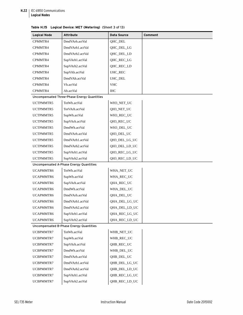
H.22
SEL-735 Meter Instruction Manual Date Code 20151012
IEC 61850 CommunicationsLogical Nodes
CPMMTR4 DmdVArh.actVal QHC_DEL
CPMMTR4 DmdVArh1.actVal QHC_DEL_LG
CPMMTR4 DmdVArh2.actVal QHC_DEL_LD
CPMMTR4 SupVArh1.actVal QHC_REC_LG
CPMMTR4 SupVArh2.actVal QHC_REC_LD
CPMMTR4 SupVAh.actVal UHC_REC
CPMMTR4 DmdVAh.actVal UHC_DEL
CPMMTR4 Vh.actVal VHC
CPMMTR4 Ah.actVal IHC
Uncompensated Three-Phase Energy Quantities
UCTPMMTR5 TotWh.actVal WH3_NET_UC
UCTPMMTR5 TotVArh.actVal QH3_NET_UC
UCTPMMTR5 SupWh.actVal WH3_REC_UC
UCTPMMTR5 SupVArh.actVal QH3_REC_UC
UCTPMMTR5 DmdWh.actVal WH3_DEL_UC
UCTPMMTR5 DmdVArh.actVal QH3_DEL_UC
UCTPMMTR5 DmdVArh1.actVal QH3_DEL_LG_UC
UCTPMMTR5 DmdVArh2.actVal QH3_DEL_LD_UC
UCTPMMTR5 SupVArh1.actVal QH3_REC_LG_UC
UCTPMMTR5 SupVArh2.actVal QH3_REC_LD_UC
Uncompensated A-Phase Energy Quantities
UCAPMMTR6 TotWh.actVal WHA_NET_UC
UCAPMMTR6 SupWh.actVal WHA_REC_UC
UCAPMMTR6 SupVArh.actVal QHA_REC_UC
UCAPMMTR6 DmdWh.actVal WHA_DEL_UC
UCAPMMTR6 DmdVArh.actVal QHA_DEL_UC
UCAPMMTR6 DmdVArh1.actVal QHA_DEL_LG_UC
UCAPMMTR6 DmdVArh2.actVal QHA_DEL_LD_UC
UCAPMMTR6 SupVArh1.actVal QHA_REC_LG_UC
UCAPMMTR6 SupVArh2.actVal QHA_REC_LD_UC
Uncompensated B-Phase Energy Quantities
UCBPMMTR7 TotWh.actVal WHB_NET_UC
UCBPMMTR7 SupWh.actVal WHB_REC_UC
UCBPMMTR7 SupVArh.actVal QHB_REC_UC
UCBPMMTR7 DmdWh.actVal WHB_DEL_UC
UCBPMMTR7 DmdVArh.actVal QHB_DEL_UC
UCBPMMTR7 DmdVArh1.actVal QHB_DEL_LG_UC
UCBPMMTR7 DmdVArh2.actVal QHB_DEL_LD_UC
UCBPMMTR7 SupVArh1.actVal QHB_REC_LG_UC
UCBPMMTR7 SupVArh2.actVal QHB_REC_LD_UC
Table H.15 Logical Device: MET (Metering) (Sheet 3 of 13)
Logical Node Attribute Data Source Comment
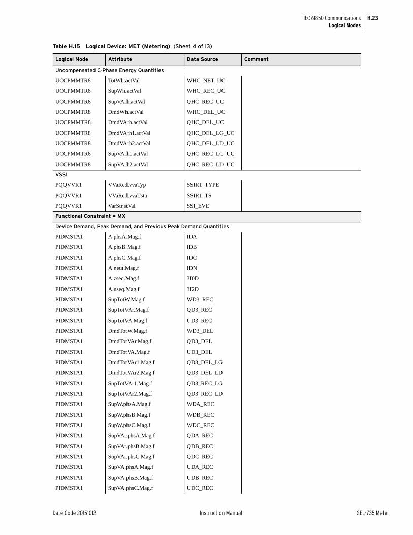
H.23
Date Code 20151012 Instruction Manual SEL-735 Meter
IEC 61850 CommunicationsLogical Nodes
Uncompensated C-Phase Energy Quantities
UCCPMMTR8 TotWh.actVal WHC_NET_UC
UCCPMMTR8 SupWh.actVal WHC_REC_UC
UCCPMMTR8 SupVArh.actVal QHC_REC_UC
UCCPMMTR8 DmdWh.actVal WHC_DEL_UC
UCCPMMTR8 DmdVArh.actVal QHC_DEL_UC
UCCPMMTR8 DmdVArh1.actVal QHC_DEL_LG_UC
UCCPMMTR8 DmdVArh2.actVal QHC_DEL_LD_UC
UCCPMMTR8 SupVArh1.actVal QHC_REC_LG_UC
UCCPMMTR8 SupVArh2.actVal QHC_REC_LD_UC
VSSI
PQQVVR1 VVaRcd.vvaTyp SSIR1_TYPE
PQQVVR1 VVaRcd.vvaTsta SSIR1_TS
PQQVVR1 VarStr.stVal SSI_EVE
Functional Constraint = MX
Device Demand, Peak Demand, and Previous Peak Demand Quantities
PIDMSTA1 A.phsA.Mag.f IDA
PIDMSTA1 A.phsB.Mag.f IDB
PIDMSTA1 A.phsC.Mag.f IDC
PIDMSTA1 A.neut.Mag.f IDN
PIDMSTA1 A.zseq.Mag.f 3I0D
PIDMSTA1 A.nseq.Mag.f 3I2D
PIDMSTA1 SupTotW.Mag.f WD3_REC
PIDMSTA1 SupTotVAr.Mag.f QD3_REC
PIDMSTA1 SupTotVA.Mag.f UD3_REC
PIDMSTA1 DmdTotW.Mag.f WD3_DEL
PIDMSTA1 DmdTotVAr.Mag.f QD3_DEL
PIDMSTA1 DmdTotVA.Mag.f UD3_DEL
PIDMSTA1 DmdTotVAr1.Mag.f QD3_DEL_LG
PIDMSTA1 DmdTotVAr2.Mag.f QD3_DEL_LD
PIDMSTA1 SupTotVAr1.Mag.f QD3_REC_LG
PIDMSTA1 SupTotVAr2.Mag.f QD3_REC_LD
PIDMSTA1 SupW.phsA.Mag.f WDA_REC
PIDMSTA1 SupW.phsB.Mag.f WDB_REC
PIDMSTA1 SupW.phsC.Mag.f WDC_REC
PIDMSTA1 SupVAr.phsA.Mag.f QDA_REC
PIDMSTA1 SupVAr.phsB.Mag.f QDB_REC
PIDMSTA1 SupVAr.phsC.Mag.f QDC_REC
PIDMSTA1 SupVA.phsA.Mag.f UDA_REC
PIDMSTA1 SupVA.phsB.Mag.f UDB_REC
PIDMSTA1 SupVA.phsC.Mag.f UDC_REC
Table H.15 Logical Device: MET (Metering) (Sheet 4 of 13)
Logical Node Attribute Data Source Comment

H.24
SEL-735 Meter Instruction Manual Date Code 20151012
IEC 61850 CommunicationsLogical Nodes
PIDMSTA1 DmdW.phsA.Mag.f WDA_DEL
PIDMSTA1 DmdW.phsB.Mag.f WDB_DEL
PIDMSTA1 DmdW.phsC.Mag.f WDC_DEL
PIDMSTA1 DmdVAr.phsA.Mag.f QDA_DEL
PIDMSTA1 DmdVAr.phsB.Mag.f QDB_DEL
PIDMSTA1 DmdVAr.phsC.Mag.f QDC_DEL
PIDMSTA1 DmdVA.phsA.Mag.f UDA_DEL
PIDMSTA1 DmdVA.phsB.Mag.f UDB_DEL
PIDMSTA1 DmdVA.phsC.Mag.f UDC_DEL
PIDMSTA1 DmdVAr1.phsA.Mag.f QDA_DEL_LG
PIDMSTA1 DmdVAr1.phsB.Mag.f QDB_DEL_LG
PIDMSTA1 DmdVAr1.phsC.Mag.f QDC_DEL_LG
PIDMSTA1 DmdVAr2.phsA.Mag.f QDA_DEL_LD
PIDMSTA1 DmdVAr2.phsB.Mag.f QDB_DEL_LD
PIDMSTA1 DmdVAr2.phsC.Mag.f QDC_DEL_LD
PIDMSTA1 SupVAr1.phsA.Mag.f QDA_REC_LG
PIDMSTA1 SupVAr1.phsB.Mag.f QDB_REC_LG
PIDMSTA1 SupVAr1.phsC.Mag.f QDC_REC_LG
PIDMSTA1 SupVAr2.phsA.Mag.f QDA_REC_LD
PIDMSTA1 SupVAr2.phsB.Mag.f QDB_REC_LD
PIDMSTA1 SupVAr2.phsC.Mag.f QDC_REC_LD
Device Peak Demand
PKDMSTA2 A.phsA.Mag.f IPA
PKDMSTA2 A.phsB.Mag.f IPB
PKDMSTA2 A.phsC.Mag.f IPC
PKDMSTA2 A.neut.Mag.f IPN
PKDMSTA2 A.zseq.Mag.f 3I0P
PKDMSTA2 A.nseq.Mag.f 3I2P
PKDMSTA2 SupTotW.Mag.f WP3_REC
PKDMSTA2 SupTotVAr.Mag.f QP3_REC
PKDMSTA2 SupTotVA.Mag.f UP3_REC
PKDMSTA2 DmdTotW.Mag.f WP3_DEL
PKDMSTA2 DmdTotVAr.Mag.f QP3_DEL
PKDMSTA2 DmdTotVA.Mag.f UP3_DEL
PKDMSTA2 DmdTotVAr1.Mag.f QP3_DEL_LG
PKDMSTA2 DmdTotVAr2.Mag.f QP3_DEL_LD
PKDMSTA2 SupTotVAr1.Mag.f QP3_REC_LG
PKDMSTA2 SupTotVAr2.Mag.f QP3_REC_LD
PKDMSTA2 SupW.phsA.Mag.f WPA_REC
PKDMSTA2 SupW.phsB.Mag.f WPB_REC
PKDMSTA2 SupW.phsC.Mag.f WPC_REC
Table H.15 Logical Device: MET (Metering) (Sheet 5 of 13)
Logical Node Attribute Data Source Comment

H.25
Date Code 20151012 Instruction Manual SEL-735 Meter
IEC 61850 CommunicationsLogical Nodes
PKDMSTA2 SupVAr.phsA.Mag.f QPA_REC
PKDMSTA2 SupVAr.phsB.Mag.f QPB_REC
PKDMSTA2 SupVAr.phsC.Mag.f QPC_REC
PKDMSTA2 SupVA.phsA.Mag.f UPA_REC
PKDMSTA2 SupVA.phsB.Mag.f UPB_REC
PKDMSTA2 SupVA.phsC.Mag.f UPC_REC
PKDMSTA2 DmdW.phsA.Mag.f WPA_DEL
PKDMSTA2 DmdW.phsB.Mag.f WPB_DEL
PKDMSTA2 DmdW.phsC.Mag.f WPC_DEL
PKDMSTA2 DmdVAr.phsA.Mag.f QPA_DEL
PKDMSTA2 DmdVAr.phsB.Mag.f QPB_DEL
PKDMSTA2 DmdVAr.phsC.Mag.f QPC_DEL
PKDMSTA2 DmdVA.phsA.Mag.f UPA_DEL
PKDMSTA2 DmdVA.phsB.Mag.f UPB_DEL
PKDMSTA2 DmdVA.phsC.Mag.f UPC_DEL
PKDMSTA2 DmdVAr1.phsA.Mag.f QPA_DEL_LG
PKDMSTA2 DmdVAr1.phsB.Mag.f QPB_DEL_LG
PKDMSTA2 DmdVAr1.phsC.Mag.f QPC_DEL_LG
PKDMSTA2 DmdVAr2.phsA.Mag.f QPA_DEL_LD
PKDMSTA2 DmdVAr2.phsB.Mag.f QPB_DEL_LD
PKDMSTA2 DmdVAr2.phsC.Mag.f QPC_DEL_LD
PKDMSTA2 SupVAr1.phsA.Mag.f QPA_REC_LG
PKDMSTA2 SupVAr1.phsB.Mag.f QPB_REC_LG
PKDMSTA2 SupVAr1.phsC.Mag.f QPC_REC_LG
PKDMSTA2 SupVAr2.phsA.Mag.f QPA_REC_LD
PKDMSTA2 SupVAr2.phsB.Mag.f QPB_REC_LD
PKDMSTA2 SupVAr2.phsC.Mag.f QPC_REC_LD
Device Previous Peak Demand
PPDMSTA3 A.phsA.Mag.f IPPA
PPDMSTA3 A.phsB.Mag.f IPPB
PPDMSTA3 A.phsC.Mag.f IPPC
PPDMSTA3 A.neut.Mag.f IPPN
PPDMSTA3 A.zseq.Mag.f 3I0PP
PPDMSTA3 A.nseq.Mag.f 3I2PP
PPDMSTA3 SupTotW.Mag.f WPP3_REC
PPDMSTA3 SupTotVAr.Mag.f QPP3_REC
PPDMSTA3 SupTotVA.Mag.f UPP3_REC
PPDMSTA3 DmdTotW.Mag.f WPP3_DEL
PPDMSTA3 DmdTotVAr.Mag.f QPP3_DEL
PPDMSTA3 DmdTotVA.Mag.f UPP3_DEL
PPDMSTA3 DmdTotVAr1.Mag.f QPP3_DEL_LG
Table H.15 Logical Device: MET (Metering) (Sheet 6 of 13)
Logical Node Attribute Data Source Comment

H.26
SEL-735 Meter Instruction Manual Date Code 20151012
IEC 61850 CommunicationsLogical Nodes
PPDMSTA3 DmdTotVAr2.Mag.f QPP3_DEL_LD
PPDMSTA3 SupTotVAr1.Mag.f QPP3_REC_LG
PPDMSTA3 SupTotVAr2.Mag.f QPP3_REC_LD
PPDMSTA3 SupW.phsA.Mag.f WPPA_REC
PPDMSTA3 SupW.phsB.Mag.f WPPB_REC
PPDMSTA3 SupW.phsC.Mag.f WPPC_REC
PPDMSTA3 SupVAr.phsA.Mag.f QPPA_REC
PPDMSTA3 SupVAr.phsB.Mag.f QPPB_REC
PPDMSTA3 SupVAr.phsC.Mag.f QPPC_REC
PPDMSTA3 SupVA.phsA.Mag.f UPPA_REC
PPDMSTA3 SupVA.phsB.Mag.f UPPB_REC
PPDMSTA3 SupVA.phsC.Mag.f UPPC_REC
PPDMSTA3 DmdW.phsA.Mag.f WPPA_DEL
PPDMSTA3 DmdW.phsB.Mag.f WPPB_DEL
PPDMSTA3 DmdW.phsC.Mag.f WPPC_DEL
PPDMSTA3 DmdVAr.phsA.Mag.f QPPA_DEL
PPDMSTA3 DmdVAr.phsB.Mag.f QPPB_DEL
PPDMSTA3 DmdVAr.phsC.Mag.f QPPC_DEL
PPDMSTA3 DmdVA.phsA.Mag.f UPPA_DEL
PPDMSTA3 DmdVA.phsB.Mag.f UPPB_DEL
PPDMSTA3 DmdVA.phsC.Mag.f UPPC_DEL
PPDMSTA3 DmdVAr1.phsA.Mag.f QPPA_DEL_LG
PPDMSTA3 DmdVAr1.phsB.Mag.f QPPB_DEL_LG
PPDMSTA3 DmdVAr1.phsC.Mag.f QPPC_DEL_LG
PPDMSTA3 DmdVAr2.phsA.Mag.f QPPA_DEL_LD
PPDMSTA3 DmdVAr2.phsB.Mag.f QPPB_DEL_LD
PPDMSTA3 DmdVAr2.phsC.Mag.f QPPC_DEL_LD
PPDMSTA3 SupVAr1.phsA.Mag.f QPPA_REC_LG
PPDMSTA3 SupVAr1.phsB.Mag.f QPPB_REC_LG
PPDMSTA3 SupVAr1.phsC.Mag.f QPPC_REC_LG
PPDMSTA3 SupVAr2.phsA.Mag.f QPPA_REC_LD
PPDMSTA3 SupVAr2.phsB.Mag.f QPPB_REC_LD
PPDMSTA3 SupVAr2.phsC.Mag.f QPPC_REC_LD
Uncompensated Device Present Interval Demand
UCPIDMSTA4 SupTotW.Mag.f WD3_REC_UC
UCPIDMSTA4 SupTotVAr.Mag.f QD3_REC_UC
UCPIDMSTA4 DmdTotW.Mag.f WD3_DEL_UC
UCPIDMSTA4 DmdTotVAr.Mag.f QD3_DEL_UC
UCPIDMSTA4 DmdTotVAr1.Mag.f QD3_DEL_LG_UC
UCPIDMSTA4 DmdTotVAr2.Mag.f QD3_DEL_LD_UC
UCPIDMSTA4 SupTotVAr1.Mag.f QD3_REC_LG_UC
Table H.15 Logical Device: MET (Metering) (Sheet 7 of 13)
Logical Node Attribute Data Source Comment

H.27
Date Code 20151012 Instruction Manual SEL-735 Meter
IEC 61850 CommunicationsLogical Nodes
UCPIDMSTA4 SupTotVAr2.Mag.f QD3_REC_LD_UC
UCPIDMSTA4 SupW.phsA.Mag.f WDA_REC_UC
UCPIDMSTA4 SupW.phsB.Mag.f WDB_REC_UC
UCPIDMSTA4 SupW.phsC.Mag.f WDC_REC_UC
UCPIDMSTA4 SupVAr.phsA.Mag.f QDA_REC_UC
UCPIDMSTA4 SupVAr.phsB.Mag.f QDB_REC_UC
UCPIDMSTA4 SupVAr.phsC.Mag.f QDC_REC_UC
UCPIDMSTA4 DmdW.phsA.Mag.f WDA_DEL_UC
UCPIDMSTA4 DmdW.phsB.Mag.f WDB_DEL_UC
UCPIDMSTA4 DmdW.phsC.Mag.f WDC_DEL_UC
UCPIDMSTA4 DmdVAr.phsA.Mag.f QDA_DEL_UC
UCPIDMSTA4 DmdVAr.phsB.Mag.f QDB_DEL_UC
UCPIDMSTA4 DmdVAr.phsC.Mag.f QDC_DEL_UC
UCPIDMSTA4 DmdVAr1.phsA.Mag.f QDA_DEL_LG_UC
UCPIDMSTA4 DmdVAr1.phsB.Mag.f QDB_DEL_LG_UC
UCPIDMSTA4 DmdVAr1.phsC.Mag.f QDC_DEL_LG_UC
UCPIDMSTA4 DmdVAr2.phsA.Mag.f QDA_DEL_LD_UC
UCPIDMSTA4 DmdVAr2.phsB.Mag.f QDB_DEL_LD_UC
UCPIDMSTA4 DmdVAr2.phsC.Mag.f QDC_DEL_LD_UC
UCPIDMSTA4 SupVAr1.phsA.Mag.f QDA_REC_LG_UC
UCPIDMSTA4 SupVAr1.phsB.Mag.f QDB_REC_LG_UC
UCPIDMSTA4 SupVAr1.phsC.Mag.f QDC_REC_LG_UC
UCPIDMSTA4 SupVAr2.phsA.Mag.f QDA_REC_LD_UC
UCPIDMSTA4 SupVAr2.phsB.Mag.f QDB_REC_LD_UC
UCPIDMSTA4 SupVAr2.phsC.Mag.f QDC_REC_LD_UC
Uncompensated Device Peak Demand
UCPKDMSTA5 SupTotW.Mag.f WP3_REC_UC
UCPKDMSTA5 SupTotVAr.Mag.f QP3_REC_UC
UCPKDMSTA5 DmdTotW.Mag.f WP3_DEL_UC
UCPKDMSTA5 DmdTotVAr.Mag.f QP3_DEL_UC
UCPKDMSTA5 DmdTotVAr1.Mag.f QP3_DEL_LG_UC
UCPKDMSTA5 DmdTotVAr2.Mag.f QP3_DEL_LD_UC
UCPKDMSTA5 SupTotVAr1.Mag.f QP3_REC_LG_UC
UCPKDMSTA5 SupTotVAr2.Mag.f QP3_REC_LD_UC
UCPKDMSTA5 SupW.phsA.Mag.f WPA_REC_UC
UCPKDMSTA5 SupW.phsB.Mag.f WPB_REC_UC
UCPKDMSTA5 SupW.phsC.Mag.f WPC_REC_UC
UCPKDMSTA5 SupVAr.phsA.Mag.f QPA_REC_UC
UCPKDMSTA5 SupVAr.phsB.Mag.f QPB_REC_UC
UCPKDMSTA5 SupVAr.phsC.Mag.f QPC_REC_UC
UCPKDMSTA5 DmdW.phsA.Mag.f WPA_DEL_UC
Table H.15 Logical Device: MET (Metering) (Sheet 8 of 13)
Logical Node Attribute Data Source Comment

H.28
SEL-735 Meter Instruction Manual Date Code 20151012
IEC 61850 CommunicationsLogical Nodes
UCPKDMSTA5 DmdW.phsB.Mag.f WPB_DEL_UC
UCPKDMSTA5 DmdW.phsC.Mag.f WPC_DEL_UC
UCPKDMSTA5 DmdVAr.phsA.Mag.f QPA_DEL_UC
UCPKDMSTA5 DmdVAr.phsB.Mag.f QPB_DEL_UC
UCPKDMSTA5 DmdVAr.phsC.Mag.f QPC_DEL_UC
UCPKDMSTA5 DmdVAr1.phsA.Mag.f QPA_DEL_LG_UC
UCPKDMSTA5 DmdVAr1.phsB.Mag.f QPB_DEL_LG_UC
UCPKDMSTA5 DmdVAr1.phsC.Mag.f QPC_DEL_LG_UC
UCPKDMSTA5 DmdVAr2.phsA.Mag.f QPA_DEL_LD_UC
UCPKDMSTA5 DmdVAr2.phsB.Mag.f QPB_DEL_LD_UC
UCPKDMSTA5 DmdVAr2.phsC.Mag.f QPC_DEL_LD_UC
UCPKDMSTA5 SupVAr1.phsA.Mag.f QPA_REC_LG_UC
UCPKDMSTA5 SupVAr1.phsB.Mag.f QPB_REC_LG_UC
UCPKDMSTA5 SupVAr1.phsC.Mag.f QPC_REC_LG_UC
UCPKDMSTA5 SupVAr2.phsA.Mag.f QPA_REC_LD_UC
UCPKDMSTA5 SupVAr2.phsB.Mag.f QPB_REC_LD_UC
UCPKDMSTA5 SupVAr2.phsC.Mag.f QPC_REC_LD_UC
Uncompensated Device Previous Peak Demand
UCPPDMSTA6 SupTotW.Mag.f WPP3_REC_UC
UCPPDMSTA6 SupTotVAr.Mag.f QPP3_REC_UC
UCPPDMSTA6 DmdTotW.Mag.f WPP3_DEL_UC
UCPPDMSTA6 DmdTotVAr.Mag.f QPP3_DEL_UC
UCPPDMSTA6 DmdTotVAr1.Mag.f QPP3_DEL_LG_UC
UCPPDMSTA6 DmdTotVAr2.Mag.f QPP3_DEL_LD_UC
UCPPDMSTA6 SupTotVAr1.Mag.f QPP3_REC_LG_UC
UCPPDMSTA6 SupTotVAr2.Mag.f QPP3_REC_LD_UC
UCPPDMSTA6 SupW.phsA.Mag.f WPPA_REC_UC
UCPPDMSTA6 SupW.phsB.Mag.f WPPB_REC_UC
UCPPDMSTA6 SupW.phsC.Mag.f WPPC_REC_UC
UCPPDMSTA6 SupVAr.phsA.Mag.f QPPA_REC_UC
UCPPDMSTA6 SupVAr.phsB.Mag.f QPPB_REC_UC
UCPPDMSTA6 SupVAr.phsC.Mag.f QPPC_REC_UC
UCPPDMSTA6 DmdW.phsA.Mag.f WPPA_DEL_UC
UCPPDMSTA6 DmdW.phsB.Mag.f WPPB_DEL_UC
UCPPDMSTA6 DmdW.phsC.Mag.f WPPC_DEL_UC
UCPPDMSTA6 DmdVAr.phsA.Mag.f QPPA_DEL_UC
UCPPDMSTA6 DmdVAr.phsB.Mag.f QPPB_DEL_UC
UCPPDMSTA6 DmdVAr.phsC.Mag.f QPPC_DEL_UC
UCPPDMSTA6 DmdVAr1.phsA.Mag.f QPPA_DEL_LG_UC
UCPPDMSTA6 DmdVAr1.phsB.Mag.f QPPB_DEL_LG_UC
UCPPDMSTA6 DmdVAr1.phsC.Mag.f QPPC_DEL_LG_UC
Table H.15 Logical Device: MET (Metering) (Sheet 9 of 13)
Logical Node Attribute Data Source Comment

H.29
Date Code 20151012 Instruction Manual SEL-735 Meter
IEC 61850 CommunicationsLogical Nodes
UCPPDMSTA6 DmdVAr2.phsA.Mag.f QPPA_DEL_LD_UC
UCPPDMSTA6 DmdVAr2.phsB.Mag.f QPPB_DEL_LD_UC
UCPPDMSTA6 DmdVAr2.phsC.Mag.f QPPC_DEL_LD_UC
UCPPDMSTA6 SupVAr1.phsA.Mag.f QPPA_REC_LG_UC
UCPPDMSTA6 SupVAr1.phsB.Mag.f QPPB_REC_LG_UC
UCPPDMSTA6 SupVAr1.phsC.Mag.f QPPC_REC_LG_UC
UCPPDMSTA6 SupVAr2.phsA.Mag.f QPPA_REC_LD_UC
UCPPDMSTA6 SupVAr2.phsB.Mag.f QPPB_REC_LD_UC
UCPPDMSTA6 SupVAr2.phsC.Mag.f QPPC_REC_LD_UC
Device Flicker Quantities
METMFLK1 PhPiMax.phsA.cVal.mag.f PINST_VA
METMFLK1 PhPiMax.phsB.cVal.mag.f PINTS_VB
METMFLK1 PhPiMax.phsC.cVal.mag.f PINTS_VC
METMFLK1 PhPst.phsA.cVal.mag.f PST_1MIN_VA
METMFLK1 PhPst.phsB.cVal.mag.f PST_1MIN_VB
METMFLK1 PhPst.phsC.cVal.mag.f PST_1MIN_VC
METMFLK1 PhPst1.phsA.cVal.mag.f PST_10MIN_VA
METMFLK1 PhPst1.phsB.cVal.mag.f PST_10MIN_VB
METMFLK1 PhPst1.phsC.cVal.mag.f PST_10MIN_VC
METMFLK1 PhPlt.phsA.cVal.mag.f PLT_VA
METMFLK1 PhPlt.phsB.cVal.mag.f PLT_VB
METMFLK1 PhPlt.phsC.cVal.mag.f PLT_VC
METMFLK1 PhpiMaxTms.cVal.mag.f SEC_PINST
METMFLK1 PhPstTms.cVal.mag.f SEC_PST
METMFLK1 TmsPhpltTms.cVal.mag.f SEC_PLT
Device Fundamental Quantities
FUNDMMXU1 TotW.Mag.f W3_FUND
FUNDMMXU1 TotVAr.Mag.f Q3_FUND
FUNDMMXU1 TotVA.Mag.f S3_FUND
FUNDMMXU1 TotVAr1.Mag.f Q3_DEL_LG
FUNDMMXU1 TotVAr2.Mag.f Q3_DEL_LD
FUNDMMXU1 TotVAr3.Mag.f Q3_REC_LG
FUNDMMXU1 TotVAr4.Mag.f Q3_REC_LD
FUNDMMXU1 TotPF.Mag.f PFD3
FUNDMMXU1 Hz.Mag.f FREQ
FUNDMMXU1 PPV.phsAB.cVal.mag.f VAB_FUND
FUNDMMXU1 PPV.phsAB.cVal.ang.f VAB_ANG
FUNDMMXU1 PPV.phsBC.cVal.mag.f VBC_FUND
FUNDMMXU1 PPV.phsBC.cVal.ang.f VBC_ANG
FUNDMMXU1 PPV.phsCA.cVal.mag.f VCA_FUND
FUNDMMXU1 PPV.phsCA.cVal.ang.f VCA_ANG
Table H.15 Logical Device: MET (Metering) (Sheet 10 of 13)
Logical Node Attribute Data Source Comment

H.30
SEL-735 Meter Instruction Manual Date Code 20151012
IEC 61850 CommunicationsLogical Nodes
FUNDMMXU1 PhV.phsA.cVal.mag.f VA_FUND
FUNDMMXU1 PhV.phsA.cVal.ang.f VA_ANG
FUNDMMXU1 PhV.phsB.cVal.mag.f VB_FUND
FUNDMMXU1 PhV.phsB.cVal.ang.f VB_ANG
FUNDMMXU1 PhV.phsC.cVal.mag.f VC_FUND
FUNDMMXU1 PhV.phsC.cVal.ang.f VC_ANG
FUNDMMXU1 A.phsA.cVal.mag.f IA_FUND
FUNDMMXU1 A.phsA.cVal.ang.f IA_ANG
FUNDMMXU1 A.phsB.cVal.mag.f IB_FUND
FUNDMMXU1 A.phsB.cVal.ang.f IB_ANG
FUNDMMXU1 A.phsC.cVal.mag.f IC_FUND
FUNDMMXU1 A.phsC.cVal.ang.f IC_ANG
FUNDMMXU1 A.neut.cVal.mag.f IN_FUND
FUNDMMXU1 A.neut.cVal.ang.f IN_ANG
FUNDMMXU1 W.phsA.cVal.mag.f WA_FUND
FUNDMMXU1 W.phsB.cVal.mag.f WB_FUND
FUNDMMXU1 W.phsC.cVal.mag.f WC_FUND
FUNDMMXU1 VAr.phsA.cVal.mag.f QA_FUND
FUNDMMXU1 VAr.phsB.cVal.mag.f QB_FUND
FUNDMMXU1 VAr.phsC.cVal.mag.f QC_FUND
FUNDMMXU1 VA.phsA.cVal.mag.f SA_FUND
FUNDMMXU1 VA.phsB.cVal.mag.f SB_FUND
FUNDMMXU1 VA.phsC.cVal.mag.f SC_FUND
FUNDMMXU1 VAr1.phsA.cVal.mag.f QA_DEL_LG
FUNDMMXU1 VAr1.phsB.cVal.mag.f QB_DEL_LG
FUNDMMXU1 VAr1.phsC.cVal.mag.f QC_DEL_LG
FUNDMMXU1 VAr2.phsA.cVal.mag.f QA_DEL_LD
FUNDMMXU1 VAr2.phsB.cVal.mag.f QB_DEL_LD
FUNDMMXU1 VAr2.phsC.cVal.mag.f QC_DEL_LD
FUNDMMXU1 VAr3.phsA.cVal.mag.f QA_REC_LG
FUNDMMXU1 VAr3.phsB.cVal.mag.f QB_REC_LG
FUNDMMXU1 VAr3.phsC.cVal.mag.f QC_REC_LG
FUNDMMXU1 VAr4.phsA.cVal.mag.f QA_REC_LD
FUNDMMXU1 VAr4.phsB.cVal.mag.f QB_REC_LD
FUNDMMXU1 VAr4.phsC.cVal.mag.f QC_REC_LD
FUNDMMXU1 PF.phsA.cVal.mag.f PFDA
FUNDMMXU1 PF.phsB.cVal.mag.f PFDB
FUNDMMXU1 PF.phsC.cVal.mag.f PFDC
Device RMS Quantities
RMSMMXU2 TotW.Mag.f W3
RMSMMXU2 TotVAr.Mag.f Q3
Table H.15 Logical Device: MET (Metering) (Sheet 11 of 13)
Logical Node Attribute Data Source Comment

H.31
Date Code 20151012 Instruction Manual SEL-735 Meter
IEC 61850 CommunicationsLogical Nodes
RMSMMXU2 TotVA.Mag.f U3
RMSMMXU2 TotPF.Mag.f PFT3
RMSMMXU2 Hz.Mag.f FREQ
RMSMMXU2 PPV.phsAB.cVal.mag.f VAB
RMSMMXU2 PPV.phsBC.cVal.mag.f VBC
RMSMMXU2 PPV.phsCA.cVal.mag.f VCA
RMSMMXU2 PhV.phsA.cVal.mag.f VA
RMSMMXU2 PhV.phsB.cVal.mag.f VB
RMSMMXU2 PhV.phsC.cVal.mag.f VC
RMSMMXU2 A.phsA.cVal.mag.f IA
RMSMMXU2 A.phsB.cVal.mag.f IB
RMSMMXU2 A.phsC.cVal.mag.f IC
RMSMMXU2 A.neut.cVal.mag.f IN
RMSMMXU2 W.phsA.cVal.mag.f WA
RMSMMXU2 W.phsB.cVal.mag.f WB
RMSMMXU2 W.phsC.cVal.mag.f WC
RMSMMXU2 Var.phsA.cVal.mag.f QA
RMSMMXU2 Var.phsB.cVal.mag.f QB
RMSMMXU2 Var.phsC.cVal.mag.f QC
RMSMMXU2 VA.phsA.cVal.mag.f UA
RMSMMXU2 VA.phsB.cVal.mag.f UB
RMSMMXU2 VA.phsC.cVal.mag.f UC
RMSMMXU2 PF.phsA.cVal.mag.f PFTA
RMSMMXU2 PF.phsB.cVal.mag.f PFTB
RMSMMXU2 PF.phsC.cVal.mag.f PFTC
Uncompensated Device RMS Quantities
UCRMSMMXU3 TotW..Mag.f. W3_UC
UCRMSMMXU3 TotVAr..Mag.f. Q3_UC
UCRMSMMXU3 W.phsA.cVal. WA_UC
UCRMSMMXU3 W.phsB.cVal. WB_UC
UCRMSMMXU3 W.phsC.cVal. WC_UC
UCRMSMMXU3 Var.phsA.cVal. QA_UC
UCRMSMMXU3 Var.phsB.cVal. QB_UC
UCRMSMMXU3 Var.phsC.cVal. QC_UC
Device Sequence/Imbalance Quantities
SEQIMSQI1 SeqA.c1.cVal.mag.f I1_MAG
SEQIMSQI1 SeqA.c1.cVal.ang.f I1_ANG
SEQIMSQI1 SeqA.c2.cVal.mag.f 3I2_MAG
SEQIMSQI1 SeqA.c2.cVal.ang.f 3I2_ANG
SEQIMSQI1 SeqA.c3.cVal.mag.f 3I0_MAG
SEQIMSQI1 SeqA.c3.cVal.ang.f 3I0_ANG
Table H.15 Logical Device: MET (Metering) (Sheet 12 of 13)
Logical Node Attribute Data Source Comment

H.32
SEL-735 Meter Instruction Manual Date Code 20151012
IEC 61850 CommunicationsLogical Nodes
SEQIMSQI1 SeqV.c1.cVal.mag.f V1_MAG
SEQIMSQI1 SeqV.c1.cVal.ang.f V1_ANG
SEQIMSQI1 SeqV.c2.cVal.mag.f V2_MAG
SEQIMSQI1 SeqV.c2.cVal.ang.f V2_ANG
SEQIMSQI1 SeqV.c3.cVal.mag.f 3V0_MAG
SEQIMSQI1 SeqV.c3.cVal.ang.f 3V0_ANG
SEQIMSQI1 ImbNgA.Mag.f. I_IMB
SEQIMSQI1 ImbNgV.Mag.f. V_IMB
Device Power Quality Quantities
PQMHAI1 Hz.Mag.f. FREQ_PQ
PQMHAI1 HKf.phsA.cVal.mag.f KFA
PQMHAI1 HKf.phsB.cVal.mag.f KFB
PQMHAI1 HKf.phsC.cVal.mag.f KFC
PQMHAI1 ThdA.phsA.cVal.mag.f THDIA
PQMHAI1 ThdA.phsB.cVal.mag.f THDIB
PQMHAI1 ThdA.phsC.cVal.mag.f THDIC
PQMHAI1 ThdA.neut.cVal.mag.f THDIN
PQMHAI1 ThdPhV.phsA.cVal.mag.f THDVA
PQMHAI1 ThdPhV.phsB.cVal.mag.f THDVB
PQMHAI1 ThdPhV.phsC.cVal.mag.f THDVC
PQMHAI1 ThdPPV.phsA.cVal.mag.f THDVA
PQMHAI1 ThdPPV.phsB.cVal.mag.f THDVB
PQMHAI1 ThdPPV.phsC.cVal.mag.f THDVC
Max Crest Factor
PQMHAI1 HCfPhV.phsA.cVal.mag.f VACFMX
PQMHAI1 HCfPhV.phsB.cVal.mag.f VBCFMX
PQMHAI1 HCfPhV.phsC.cVal.mag.f VCCFMX
PQMHAI1 HCfPPV.phsAB.cVal.mag.f VACFMX
PQMHAI1 HCfPPV.phsBC.cVal.mag.f VBCFMX
PQMHAI1 HCfPPV.phsCA.cVal.mag.f VCCFMX
PQMHAI1 HCfA.phsA.cVal.mag.f IACFMX
PQMHAI1 HCfA.phsB.cVal.mag.f IBCFMX
PQMHAI1 HCfA.phsC.cVal.mag.f ICCFMX
PQMHAI1 HCfA.neut.cVal.mag.f INCFMX
VSSI
PQQVVR1 VVa.Mag.f. SSIR1_DEPTH
PQQVVR1 VVaTm.Mag.f. SSIR1_DUR
Table H.15 Logical Device: MET (Metering) (Sheet 13 of 13)
Logical Node Attribute Data Source Comment

Date Code 20151012 Instruction Manual SEL-735 Meter
Appendix ISynchrophasors
Instruction Manual
OverviewSynchrophasor measurement refers to the concept of providing phasor measurements (including magnitude and angle) taken on a synchronized schedule with the ability to gather these data points from multiple locations.
The SEL-735 Meter provides Phasor Measurement Unit (PMU) capabilities when connected to a high-accuracy IRIG-B time source, such as the SEL-2488 Satellite-Synchronized Clock. Synchrophasor data are available via the MET PM ASCII command and the IEEE C37.118.2-2011 Protocol (when configured with an Ethernet port).
The SEL-735 is a producer (not a consumer/client) of synchrophasor data. The synchrophasor data produced in the SEL-735 are available on the MET PM command and on the IEEE C37.118.2 protocol (not in SELOGIC or in analog quantities).
The availability of an accurate time reference over a large geographic area allows multiple devices, such as SEL-735 meters, to synchronize the gathering of power system data. Synchrophasors are still measured if the high-accuracy time source is not connected, however, the synchrophasor angle data are not accurate. The Device Word bits TSOK and PMDOK both assert when the meter is synchronized to a high-accuracy time source and can produce synchrophasor data. See Prerequisites for Synchrophasor Data on page I.3 for more information.
The SEL-735 General settings group contain the synchrophasor settings, including the choice of transmitted synchrophasor data sets. The Port 1 Ethernet settings group configure synchrophasor communications. See General Settings for Synchrophasors on page I.3 and Ethernet Port Settings for Synchrophasor Protocol IEEE C37.118.2 on page I.7.
The SEL-735 timekeeping function generates status Device Word bits and time-quality information that are important for synchrophasor measurements. The user-defined portion of the synchrophasor data message contains SELOGIC variables and programmable digital trigger information. See Synchrophasor Device Word Bits on page I.9.

I.2
SEL-735 Meter Instruction Manual Date Code 20151012
SynchrophasorsSynchrophasor Measurement
Synchrophasor MeasurementNOTE: All references to IEEE C37.118.1 in this document are references to “IEEE C37.118.1-2011 as amended by IEEE C37.118.1a-2014”.
The SEL-735 timestamps voltage and current measurements with time from the IRIG time source to produce filtered phasor data that complies with IEEE C37.118.1. Synchrophasors are specifically filtered to remove the influence from harmonics and any signal other than the fundamental waveform (nominally 50 or 60 Hz).
The phase angle is measured relative to an absolute time reference, which is represented by a cosine function in Figure I.1. Figure I.1 shows the time and angle reported by synchrophasors for two time instances. During conditions described by the standard, the SEL-735 synchrophasor values can be directly compared to values from other phasor measurement units that conform to IEEE C37.118.1.
Figure I.1 Phase Angle of Waveform at Two Time Instances
The TSOK Device Word bit asserts when the SEL-735 determines that the IRIG-B time source has sufficient accuracy. The SEL-735 measures synchrophasors in the absence of an accurate source, however, the SEL-735 suppresses the MET PM command.
The SEL-735 scales the phasors in primary units, as determined by group settings PTR and CTR.
When synchrophasor measurement is enabled, the SEL-735 creates the synchrophasor data at a user-configurable rate.
The SEL-735 supports the protocol defined in IEEE C37.118.2-2011, Standard for Synchrophasor Data Transfer for Power Systems. The value of synchrophasor data increases greatly when the data can be shared over a communications network in real time. The SEL-735 publishes data in the format defined by IEEE C37.118.2 which allows for a centralized device to collect data efficiently from several phasor measurement units (PMUs). Some possible uses of a system-wide synchrophasor system include the following:
➤ Power-system state measurement
➤ Wide-area network control schemes
➤ Small-signal analysis
➤ Power-system disturbance analysis
t
10:00:00:0166670 Degrees
10:00:00:0000000 Degrees

I.3
Date Code 20151012 Instruction Manual SEL-735 Meter
SynchrophasorsGeneral Settings for Synchrophasors
Prerequisites for Synchrophasor Data
The SEL-735 supports the IEEE C37.118.2 protocol through an Ethernet port. The EIA-232, EIA-485, and Ethernet ports support the MET PM command.
Follow these steps to ensure synchrophasor measurement accuracy:
1. Connect the SEL-735 to a high-accuracy IRIG clock with low jitter and absolute time accuracy of 1 µs or better and with IEEE C37.118 control bits enabled. Under these conditions, the Device Word bits TSOK, TIRIG, and PMDOK assert.
2. Maintain current signals as listed in Specifications, and set VBASE to the appropriate nominal voltage.
3. Maintain a positive-sequence voltage greater than or equal to 5% of VBASE (apply balanced three-phase voltages).
4. Set UTC_OFF to match the UTC offset of the IRIG signal.
New Functionality in IEEE C37.118.1-2011-Compliant Synchrophasor
When compared to IEEE C37.118-2005, IEEE C37.118.1 has several differences, some of which are outlined here.
Performance Classes. IEEE C37.118.1 introduced two performance classes, P Class and M class. The SEL-735 provides P class synchrophasors. P class (protection) is for applications requiring faster response and less filtering. M class (measurement) is for applications that require more filtering and do not require minimal reporting delay.
Specified Latency. IEEE C37.118.1 introduced message latency requirements. In this context, message latency is defined as the time interval between when an event occurs on the power system to the time that it is reported in data. The SEL-735 meets the message latency requirements for P class synchrophasors when using a UDP transport scheme (see PMOTS1 and PMOTS2).
Dynamic Performance. IEEE C37.118.1 introduced dynamic performance requirements, whereas the 2005 standard only specified performance when the power system was in steady state. The details of this difference and the impact on installed units is beyond the scope of this document. The SEL-735 complies with all P class performance requirements (dynamic and steady-state) of the standard.
Rate-of-Change-of-Frequency (ROCOF). IEEE C37.118.1 introduced requirements on the responsiveness of ROCOF beyond that of the 2005 standard. One effect of these changes is to make ROCOF more sensitive to noise, so care should be taken before applying the ROCOF value to a control scheme.
General Settings for SynchrophasorsThe synchrophasor settings in the General settings group are used to configure the PMU for synchrophasors. The settings are listed in Table I.1.
The Port 1 enable setting EPMIP must be set to 1 or 2 before the remaining SEL-735 synchrophasor settings are available.

I.4
SEL-735 Meter Instruction Manual Date Code 20151012
SynchrophasorsGeneral Settings for Synchrophasors
Definitions follow for the settings in Table I.1.
MRATEMRATE selects the message rate in messages per second for synchrophasor data streaming on the Ethernet port.
Choose the MRATE setting that suits the needs of your PMU application.
Table I.1 PMU Settings in the SEL-735 for IEEE C37.118 Protocol in General Settings
Setting Description Default
MRATE Messages per second
(1, 2, 5, 10, 25, or 50 when frequency := 50 Hz)
(1, 2, 4, 5, 10, 12, 15, 20, 30, or 60 when frequency := 60 Hz)
50 or 60
PMSTN Station name (16 characters) STATION A
PMID PMU hardware ID (1–65534) 1
PHDATAV Phasor data set, voltages (V1, PH, ALL, NA)
PH
VCOMP Phase voltage angle compensation (–179.99 to 180 deg)
0.00
PHDATAI Phasor data set, currents (I1, PH, ALL, NA)
PH
ICOMP Phase current angle compensation (–179.99 to 180 deg)
0.00
NUMANA Number of analog quantities (0–4) 0
PMUAQ1a
a Hidden if NUMANA < 1.
PMU analog quantity 1 W3_HALF_CYCLE
PMUAQ2b
b Hidden if NUMANA < 2.
PMU analog quantity 2 S3_HALF_CYCLE
PMUAQ3c
c Hidden if NUMANA < 3.
PMU analog quantity 3 Q3_HALF_CYCLE
PMUAQ4d
d Hidden if NUMANA < 4.
PMU analog quantity 4 THDVA
NUMDSW Number of 16-bit digital status words (0, 1)
0
TREA1 Trigger Reason bit 1 (SELOGIC) 0
TREA2 Trigger Reason bit 2 (SELOGIC) 0
TREA3 Trigger Reason bit 3 (SELOGIC) 0
TREA4 Trigger Reason bit 4 (SELOGIC) 0
PMTRIG PMU trigger (SELOGIC) TREA1 OR TREA2 OR TREA3 OR TREA4

I.5
Date Code 20151012 Instruction Manual SEL-735 Meter
SynchrophasorsGeneral Settings for Synchrophasors
PMSTN and PMID
PMSTN and PMID define the name and number of the PMU. The PMSTN setting is an ASCII string with as many as 16 characters. The PMID setting is a numeric value. Use your utility or synchrophasor data concentrator naming convention to determine these settings.
PHDATAVPHDATAV selects which voltage synchrophasors to include in the data packet. Consider the burden on your synchrophasor processor and offline storage requirements when deciding how much data to transmit.
➤ PHDATAV := V1 transmits only positive-sequence voltage, V1
➤ PHDATAV := PH transmits VA, VB, and VC or VAB, VBC, and VCA for Form 5 meters
➤ PHDATAV := ALL transmits V1, VA, VB, and VC or VAB, VBC, and VCA for Form 5 meters
➤ PHDATAV := NA does not transmit any voltages
Content of IEEE C37.118.2 Data Packets on page I.12 describes the order of synchrophasors inside the data packet.
PHDATAIPHDATAI selects which current synchrophasors to include in the data packet. Consider the burden on your synchrophasor processor and offline storage requirements when deciding how much data to transmit.
➤ PHDATAI := I1 transmits only positive-sequence current, I1
➤ PHDATA1 := PH transmits IA, IB, IC, and IN
➤ PHDATAI := ALL transmits I1, IA, IB, IC, and IN
➤ PHDATAI := NA does not transmit any currents
Content of IEEE C37.118.2 Data Packets on page I.12 describes the order of synchrophasors inside the data packet.
Synchrophasors are only transmitted if specified to be included by the PHDATAV and PHDATAI settings. For example, if PHDATAV := ALL and PHDATAI := I1, selected phase voltages are transmitted first, followed by positive-sequence current and positive-sequence voltage.
VCOMP and ICOMP
The VCOMP setting allows correction for any steady-state voltage phase errors (from the potential transformers or secondary wiring). The ICOMP setting allows correction for any steady-state current phase errors (from the current transformers or secondary wiring).
The instrumentation transformers (PTs or CTs) and the interconnecting cables introduce a phase shift in the measured signal. Settings VCOMP and ICOMP, entered in degrees, are added to the measured phasor angles to create the corrected phasor angles, as shown in Figure I.2 and Figure I.3. The VCOMP and ICOMP settings may be positive or negative values. Alternatively, use Instrument Transformer Compensation (ITC) to correct for the phase shift; see

I.6
SEL-735 Meter Instruction Manual Date Code 20151012
SynchrophasorsGeneral Settings for Synchrophasors
Instrument Transformer Compensation on page 5.6. ITC corrects for phase-angle shift on all metering interfaces whereas VCOMP and ICOMP only correct for phase-angle shift on the synchrophasors interface.
Figure I.2 Waveform at Meter Terminals May Have a Phase Shift
If the time shift on the PT measurement path COMP = 0.784 ms and the nominal frequency, freqnominal = 60Hz, use Equation to obtain the correction angle:
Equation I.1
Figure I.3 Correction of Measured Phase Angle
NUMANA, PMUAQ1, PMUAQ2, PMUAQ3, and PMUAQ4
NUMANA selects the number of user-definable analog quantities to be included in the synchrophasor data stream.
➤ Setting NUMANA := 0 sends no user-definable analog quantities.
➤ Setting NUMANA := 1–4 sends the user-definable analog quantities, as set in settings PMUAQ1–PMUAQ4.
The format of the user-defined analog data is 32-bit floating point. The meter updates these analog quantities every 200 ms.
Vpk
–Vpk
0 t
VA(t)
ActualWaveform
MeasuredWaveform
COMP
0.784 103–s 60s
1–360°• • • 16.934°=
Imaginary
RealM
MVA measured
VA corrected
Compensation Angle

I.7
Date Code 20151012 Instruction Manual SEL-735 Meter
SynchrophasorsEthernet Port Settings for Synchrophasor Protocol IEEE C37.118.2
NUMDSWNUMDSW selects the number of user-definable digital status words to be included in the synchrophasor data stream. The meter updates these digital bits every power system cycle.
The inclusion of binary data can help indicate logic status or other operational data to the synchrophasor processor.
➤ Setting NUMDSW := 0 sends no user-definable binary status words.
➤ Setting NUMDSW := 1 sends the user-definable binary status word, as listed in Table I.2.
TREA1, TREA2, TREA3, TREA4, and PMTRIGThese settings define the programmable trigger bits as allowed by IEEE C37.118.1.
Each of the four Trigger Reason settings, TREA1–TREA4, and the PMU Trigger setting, PMTRIG, are SELOGIC control equations in the General settings group. The SEL-735 evaluates these equations and places the results in Device Word bits with the same names: TREA1–TREA4 and PMTRIG.
The trigger reason equations represent the Trigger Reason bits in the STAT field of the data packet. After the trigger reason bits are set to convey a message, assert the PMTRIG equation to signal the synchrophasor processor to read the TREA1–TREA4 fields.
You can use these bits to send various messages at a low bandwidth via the synchrophasor message stream. You can also use Digital Status Words to send binary information.
Use these Trigger Reason bits if your synchrophasor system design requires these bits. The SEL-735 synchrophasor processing and protocol transmission are not affected by the status of these bits.
Ethernet Port Settings for Synchrophasor Protocol IEEE C37.118.2
IEEE C37.118.1 compliant synchrophasors are available over the IEEE C37.118.2 protocol via the Ethernet port. Table I.3 shows the associated Ethernet port settings.
Table I.2 User-Defined Digital Status Word Selected by the NUMDSW Setting
NUMDSW Setting Digital Status Words Sent Total Number of Bytes Used for Digital Values
0 None 0
1 [SV01, SV02…SV16] 2

I.8
SEL-735 Meter Instruction Manual Date Code 20151012
SynchrophasorsEthernet Port Settings for Synchrophasor Protocol IEEE C37.118.2
Definitions follow for the settings in Table I.3.
PMOTS1 and PMOTS2
PMOTS1 and PMOTS2 select the PMU output transport scheme for session 1 and 2, respectively.
➤ PMOTSn := OFF disables the connection.
➤ PMOTSn := TCP establishes a single, persistent TCP socket for transmitting and receiving synchrophasor messages (both commands and data), as illustrated in Figure I.4.
Figure I.4 TCP Connection
➤ PMOTSn := UDP_T establishes two socket connections. A nonpersistent TCP connection is used for receiving synchrophasor command messages as well as synchrophasor configuration and header response messages. A persistent UDP connection is used to transmit synchrophasor data messages. Figure I.5 depicts the UDP_T connection.
Table I.3 SEL-735 Ethernet Port Settings for Synchrophasors
Setting Description Default
EPMIP Enable PMU sessions (0–2) 0a
a Set EPMIP > 0 to enable other settings in this group.
PMOTS1 PMU output 1 transport scheme (OFF, TCP, UDP_S, UDP_T, UDP_U)
OFF
PMOIPA1 PMU output 1 client IP (remote) address (www.xxx.yyy.zzz)
192.168.1.3
PMOTCP1b
b Hidden if PMOTS1 = UDP_S.
PMU output 1 TCP/IP (local) port number (1–65534)
4712
PMOUDP1c
c Hidden if PMOTS1 = TCP.
PMU output 1 UDP/IP data(remote) port number (1–65534)
4713
PMOTS2 PMU output 2 transport scheme (OFF, TCP, UDP_S, UDP_T, UDP_U)
OFF
PMOIPA2 PMU output 2 client IP (remote) address (www.xxx.yyy.zzz)
192.168.1.4
PMOTCP2d
d Hidden if PMOTS2 = UDP_S.
PMU output 2 TCP/IP (local) port number (1–65534)
4722
PMOUDP2e
e Hidden if PMOTS2 = TCP.
PMU output 2 UDP/IP data(remote) port number (1–65534)
4713
IEEE C37.118 - Synchrophasor Command Start Request - Synchrophasor Command Stop Request - Synchrophasor Command Configuration Request 1 - Synchrophasor Command Configuration Request 2
IEEE C37.118 - Synchrophasor Measurement - Synchrophasor Configuration Response 1 - Synchrophasor Configuration Response 2
TCP Socket
(Persistent)
SEL-735

I.9
Date Code 20151012 Instruction Manual SEL-735 Meter
SynchrophasorsSynchrophasor Device Word Bits
➤ PMOTSn := UDP_U uses the same connection scheme as the UDP_T except the synchrophasor configuration and header response messages are sent over the UDP connection, as shown in Figure I.5.
Figure I.5 UDP_T and UDP_U Connections
➤ PMOTSn := UDP_S establishes a single persistent UDP socket to transmit synchrophasor messages. With this communications scheme, the meter sends a Synchrophasor Configuration Response 2 once every minute, as shown in Figure I.6.
Figure I.6 UDP_S Connection
When PMOTS ≠ UDP_S, the SEL-735 does not begin transmitting synchrophasors until it receives a start data command from the synchrophasor processor. The meter stops synchrophasor transmission when it receives the stop data command from the synchrophasor processor. The SEL-735 only responds to configuration block request messages when it is in the non-transmitting mode.
When PMOTS = UDP_S, the SEL-735 transmits synchrophasors upon startup, automatically sends configuration frames every minute, and does not process any synchrophasor commands.
The SEL-735 will meet the message latency requirements specified in section 5.5.9 of IEEE C37.118.1 when PMOTS = UDP_S, UDP_T, or UDP_U.
Synchrophasor Device Word BitsTable I.4 and Table I.5 list the SEL-735 Device Word bits that are related to synchrophasor measurement. The Synchrophasor Trigger Device Word bits in Table I.4 follow the state of the SELOGIC control equations of the same name, listed at the bottom of Table I.1. These Device Word bits are included in the IEEE C37.118 synchrophasor data frame STAT field.
IEEE C37.118 - Synchrophasor Command Start Request - Synchrophasor Command Stop Request - Synchrophasor Command Configuration Request 1 - Synchrophasor Command Configuration Request 2 If PMOTSn is UDP_T - Synchrophasor Configuration Response 1 - Synchrophasor Configuration Response 2
IEEE C37.118 - Synchrophasor Measurement If PMOTSn is UDP_U - Synchrophasor Configuration Response 1 - Synchrophasor Configuration Response 2
TCP Socket
(Nonpersistent)
UDP Socket
(Persistent)
SEL-735
IEEE C37.118 - Synchrophasor Measurement - Synchrophasor Configuration Response 2 (Sent once per minute)
UDP Socket
(Persistent)
SEL-735

I.10
SEL-735 Meter Instruction Manual Date Code 20151012
SynchrophasorsView Synchrophasors Using the MET PM Command
The Time-Synchronization Device Word bits in Table I.5 indicate the present status of the timekeeping function of the SEL-735.
View Synchrophasors Using the MET PM CommandThe MET PM ASCII command provides a means to view a SEL-735 synchrophasor measurement over a serial or Telnet connection.
There are multiple ways to use the MET PM command:
➤ As a test tool, to verify connections, phase rotation, and scaling
➤ As an analytical tool, to capture synchrophasor data at an exact time, to compare this information with similar data captured in other phasor measurement unit(s) at the same time
➤ As a method of periodically gathering synchrophasor data through a communications processor
The MET PM command displays the same set of analog synchrophasor information, regardless of the General settings PHDATAV and PHDATAI. The MET PM command functions even when the SEL-735 is not equipped with an Ethernet port, or when IEEE C37.118.2 is not set up on an Ethernet port.
The MET PM command provides an extended feature set by matching the synchrophasor and analog quantity scaling with the SEL-735 global analog quantity scaling settings such as primary/secondary and unity, kilo, and mega multipliers.
The MET PM command only operates when the SEL-735 is connected to a high-accuracy time source, as indicated by Device Word bit TSOK = logical 1.
Figure I.7 shows a sample MET PM command response. The command response is also available via the HMI > Meter PM menu in ACSELERATOR QuickSet, and has a similar format to Figure I.7.
Table I.4 Synchrophasor Trigger Device Word Bits
Name Description
PMTRIG Trigger (SELOGIC)
TREA4 Trigger Reason bit 4 (SELOGIC)
TREA3 Trigger Reason bit 3 (SELOGIC)
TREA2 Trigger Reason bit 2 (SELOGIC)
TREA1 Trigger Reason bit 1 (SELOGIC)
Table I.5 Time-Synchronization Device Word Bits
Name Description
IRIGOK Asserts while meter time is based on IRIG-B time source.
TSOK Time Synchronization OK. Asserts while time is based on an IRIG-B time source of sufficient accuracy for synchrophasor measurement.
PMDOK Phasor measurement data OK. Asserts when the SEL-735 is enabled and able to produce Synchrophasor data. A few seconds may be necessary for PMDOK to assert when the meter is first turned on, after any of the settings are changed, or when an IRIG-B time signal is first connected.

I.11
Date Code 20151012 Instruction Manual SEL-735 Meter
SynchrophasorsIEEE C37.118.2 Synchrophasor Protocol
The MET PM time command schedules the SEL-735 to display the synchrophasor measurement at a specified time, in 24-hour format. For example, entering the command MET PM 10:57:59 results in a response similar to Figure I.7 with the time stamp 10:57:59.000. For the MET PM time response to transmit over a port, the port must not have timed out at the time when the scheduled command runs. To later retrieve the results of a scheduled command, use the MET PM H command.
IEEE C37.118.2 Synchrophasor ProtocolThe SEL-735 complies with IEEE Standard for Synchrophasor Data Transfer for Power Systems, IEEE C37.118.2-2011. The protocol is available on the Ethernet port (Port 1).
NOTE: The SEL-735 takes exception to two requirements in this standard related to the STAT field: 1. The configuration change bit asserts after a configuration change, not one minute prior to a configuration change.2. The trigger bits are completely user defined, not preset as specified in the standard.
This section highlights some of the important features and options of the protocol that are available in the meter.
Settings Affect Message Contents
Select how often to transmit the synchrophasor messages (MRATE) and which phasors to transmit (PHDATAV and PHDATAI).
The meter can include as many as four user-programmable analog quantities in the synchrophasor message, as controlled by General setting NUMANA, and 0 or 16 digital status values, as controlled by General setting NUMDSW.
The SEL-735 always includes the results of four synchrophasor trigger reason bits (TREA1-TREA4), and the PMU trigger (PMTRIG) in the synchrophasor message.
=>MET PM <Enter>
FEEDER 1 Date: 02/06/15 Time: 10:57:59.000STATION A Time Source: ext
PMDOK = 1Time Quality Locked to IRIG TSOK = 1Synchrophasors
Phase Voltages Pos. Seq. Voltage VA VB VC V1MAG ( V) 3599.16 3599.05 3599.06 3599.09ANG (DEG) -44.42 -164.43 75.56 -44.43
Phase Currents Pos. Seq. Current IA IB IC IN I1MAG (A) 149.96 149.99 149.97 0.74 149.97ANG (DEG) 15.57 -104.43 135.56 66.07 15.57
FREQ (Hz) 60.000Rate-of-change of FREQ (Hz/s) 0.01
Analogs W3_HALF_CYCLE 809595.06 (W) S3_HALF_CYCLE 1618808.00 (VA) Q3_HALF_CYCLE -1401818.50 (VAR) IA 149.9571 (A)
Digitals
SV01 SV02 SV03 SV04 SV05 SV06 SV07 SV08 0 1 0 0 0 0 0 0SV09 SV10 SV11 SV12 SV13 SV14 SV15 SV16 0 0 0 0 0 0 0 0
Figure I.7 Sample MET PM Command Response

I.12
SEL-735 Meter Instruction Manual Date Code 20151012
SynchrophasorsIEEE C37.118.2 Synchrophasor Protocol
Protocol Operation The SEL-735 only transmits synchrophasor messages over the Ethernet port if PMOTS1 or PMOTS2 ≠ OFF. The connected device is typically a synchrophasor processor, such as the SEL-3373. The synchrophasor processor controls the PMU functions of the SEL-735 with IEEE C37.118 commands, including commands to start and stop synchrophasor data transmission, and commands to request a configuration block from the meter, so the synchrophasor processor can automatically build a database structure. The SEL-735 indicates in the configuration change bit when a configuration change occurs, so the synchrophasor processor can request a new configuration block and keep its database up-to-date.
Content of IEEE C37.118.2 Data Packets
Synchrophasors are transmitted in the order indicated in Table I.6 from the top to the bottom of the table. Real values are transmitted first, and imaginary values are transmitted second.
Table I.6 Synchrophasor Order in Data Stream (Voltages and Currents in PHASORS Field)
Synchrophasorsa
a Synchrophasors are transmitted as primary values with unity scaling. The meter uses settings CTR and PTR to scale the values.
Included When Settings Are as Follows:Rectangular Format (Real, Imaginary)32-Bit Floating Point Format
IAPM
IBPM
ICPM
INPM
PHDATAI := PH or ALL
VAPM
VBPM
VCPM
PHDATAV := PH or ALL (if meter is Form 9 or Form 36)
VABPM
VBCPM
VCAPM
PHDATAV := PH or ALL (if meter is Form 5)
I1PM PHDATAI := I1 or ALL
V1PM PHDATAV := V1 or ALL

Date Code 20151012 Instruction Manual SEL-735 Meter
Glossary
a Output A meter control output that closes when the output meter asserts.
b Output A meter control output that opens when the output meter asserts.
c Contact A breaker auxiliary contact that you can set to serve either as an a contact or as a b contact.
A Abbreviation for Amps or Amperes; unit of electrical current flow.
Acceptance Testing Testing that confirms that the meter meets published critical performance specifications and requirements of the intended application. Such testing involves accuracy testing and logic functions when qualifying a meter model for use on the utility system.
Access Level A meter command level with a specified set of meter information and commands. Except for Access Level 0, you must have the correct password to enter an access level.
Access Level 0 The least secure and most limited access level. No password protects this level. From this level, you must enter a password to go to a higher level.
Access Level 1 A meter command level you use to monitor (view) meter information. The default access level for the meter front panel.
Access Level E A meter command level you use for Access Level 1 functions and resetting of peak demand, maximum/minimum, crest factors, and load profile. This access level is for the meter reader.
Access Level 2 The most secure access level, from which you have total meter functionality and control of all settings types.
ACSELERATORQuickSet®
SEL-5030 Software
A Windows®-based program that simplifies settings and provides analysis support.
Analog Quantities Variables represented by such fluctuating measurable quantities as frequency, current, and voltage.
AND Operator Logical AND. An operator in Boolean SELOGIC® control equations that requires fulfillment of conditions on both sides of the operator before the equation is true.
Anti-Aliasing Filter A low-pass filter that blocks frequencies too high for the given sampling rate to accurately reproduce.
Apparent Power (S) Complex power expressed in units of volt-amperes (VA). Accounts for both real (P) and reactive (Q) power dissipated in a circuit: S = P + jQ. This is power at the fundamental frequency only; this quantity includes no harmonics.
ASCII Abbreviation for American Standard Code for Information Interchange. Defines a standard set of text characters. The SEL-735 uses ASCII text characters to communicate through the use of front-panel and rear-panel EIA-232 serial ports on the meter and through virtual serial ports.

GL.2
SEL-735 Meter Instruction Manual Date Code 20151012
GlossaryASCII Terminal—Comparison
ASCII Terminal A terminal without built-in logic or local processing capability that can only send and receive information.
Assert To activate. To fulfill the logic or electrical requirements necessary to operate a device. To set a logic condition to the true state (logical 1) of that condition. To apply a closed contact to an SEL-735 input. To close a normally open output contact. To open a normally closed output contact.
AT Modem Command SetDialing String Standard
The command language standard that Hayes Microcomputer Products, Inc. developed to control auto-dial modems from an ASCII terminal (usually EIA-232 connected) or a PC (personal computer) containing software allowing emulation of such a terminal.
Automatic Messages Messages including status failure and status warning messages that the meter generates at the serial ports and displays automatically on the front-panel LCD.
Bandpass Filter A filter that passes frequencies within a certain range and blocks all frequencies outside this range.
Bit Label The identifier for a particular bit.
Bit Value Logical 0 or logical 1.
Blondel’s Theorem This theorem states that in a system of N conductors, N-1 meter elements, properly connected, will measure the power or energy taken. The connection must be such that all voltage coils have a common tie to the conductor in which there is no current coil.
Boolean Logic Statements Statements consisting of variables that behave according to Boolean logic operators such as AND, NOT, and OR.
Checksum A method for checking the accuracy of data transmission involving summation of a group of digits and comparison of this sum to a previously calculated value.
CID Checksum identification of the firmware.
Class Designation The maximum of the watt-hour meter load range in amperes. This value is indicated on the faceplate after the abbreviation CL. Typical class designations for transformer-rated meters are CL 10 or CL 20. A typical class designation for a residential type meter is CL 200.
Cold Start Beginning a system from application of power without carryover of previous system activities.
Commissioning Testing Testing that serves to validate all system ac and dc connections and confirm that the meter, auxiliary equipment, and SCADA interface all function as intended with your settings. Perform such testing when installing a new metering system.
Common Inputs Meter control inputs that share a common terminal.
Communications Protocol A language for communication among devices.
Comparison Boolean SELOGIC control equation operation that compares two numerical values. Compares floating-point values such as currents, total counts, and other measured and calculated quantities.

GL.3
Date Code 20151012 Instruction Manual SEL-735 Meter
GlossaryConditioning Timers—Dial
Conditioning Timers Timers for conditioning Boolean values. Conditioning timers either stretch incoming pulses or allow you to require that an input take a state for a certain period before reacting to the new state.
Contact Input See Control Input.
Contact Output See Control Output.
Control Input Meter inputs for monitoring the state of external circuits. Connect auxiliary meter and circuit breaker contacts to the control inputs.
Control Output Meter outputs that affect the state of other equipment. Connect control outputs and SCADA systems.
Counter Variable or device such as a register or storage location that either records or represents the number of times an event occurs.
CT Current transformer.
CTR Current transformer ratio.
Data Bit A single unit of information that can assume a value of either logical 0 or logical 1 and can convey control, address, information, or frame check sequence data.
Data Label The identifier for a particular data item.
Data Objects Individual pieces of UCA data created from instances of common class components or data items that are instances of standard data types.
DCE Devices Data communication equipment devices (modems).
Dead Band The range of variation an analog quantity can traverse before causing a response.
Deassert To deactivate. To remove the logic or electrical requirements necessary to operate a device. To clear a logic condition to its false state (logical 0). To open the circuit or open the contacts across an SEL-735 input. To open a normally open output contact. To close a normally closed output contact.
Debounce Time The time that masks the period when meter contacts continue to move after closing; debounce time covers this indeterminate state.
Default Data Map The default map of objects and indices that the SEL-735 uses in DNP protocol.
Delta A phase-to-phase series connection of circuit elements, particularly voltage transformers or loads.
Demand Meter A measuring function that calculates a rolling average, block, or thermal average, block, of instantaneous measurements over time.
Dial The clock-type hands on an electromechanical register. The billing system must be aware of the “number of dials” on the meter to properly detect a rollover condition. Use of four- and five-dial registers is common.

GL.4
SEL-735 Meter Instruction Manual Date Code 20151012
GlossaryDial Multiplier—Event Report
Dial Multiplier The value the meter register displays multiplied by the dial multiplier to obtain kilowatt-hours. The nameplate shows the dial multiplier. For self-contained meters, a dial multiplier of one or ten is most common. Determination of the dial multiplier for transformer-rated meters occurs at installation time, depending on the transformer ratios. This multiplier applies to both the kilowatt-hour and demand (kW) readings.
DistortionPower Ratio (Dx)
The meter calculates distortion power as the ratio of average power to fundamental power and reported the result as a percentage. Calculation occurs on a per-phase or three-phase basis as follows:
where:
Dx is the distortion power ratio for the respective phase
Px_avg is the average power for the respective phase
Px is the fundamental power for the respective phase
DMSI Period The subinterval time of the demand meter time constant in demand metering.
DMTC Period The time of the demand meter time constant in demand metering.
DNP (DistributedNetwork Protocol)
Manufacturer-developed, hardware-independent communications protocol.
Dropout Time The time measured from the removal of an input signal until the output signal deasserts. You can set the time, in the case of a logic variable timer, or the dropout time can be a result of the characteristics of an element algorithm.
DTE Devices Data terminal equipment (computers, terminals, printers, meters, etc.).
Dumb Terminal See ASCII terminal.
EIA-232 Electrical definition for point-to-point serial data communications interfaces, based on the standard EIA/TIA-232. Formerly known as RS-232.
EIA-485 Electrical standard for multidrop serial data communications interfaces, based on the standard EIA/TIA-485. Formerly known as RS-485.
Element A combination of a voltage-sensing unit and a current-sensing unit that provides an output proportional to the quantities measured. For example, a Form 9 meter is a three-element meter. See also Stator.
Energy Metering Energy metering provides a look at imported power, exported power, and net usage over time.
ESD(Electrostatic Discharge)
The sudden transfer of charge between objects at different potentials caused either by direct contact or induction by an electrostatic field.
Ethernet A network physical and data link layer defined by IEEE 802.2 and IEEE 802.3.
Event History A quick look at recent meter activity that includes a standard report header, event number, date, time, type, and targets.
Event Report A text-based collection of data the meter stores in response to a triggering condition, such as an ASCII TRI command. The data show meter
Dx Px_avgPx------------------ 1–
100=

GL.5
Date Code 20151012 Instruction Manual SEL-735 Meter
GlossaryEvent Summary—IED
measurements before and after the trigger, in addition to the states of elements each processing interval.
Event Summary A shortened version of stored event reports. An event summary includes items such as event date, event time, and event type.
The meter sends an event report summary (if auto messaging is enabled) to the meter serial port a few seconds after an event.
F_TRIG Falling-edge trigger. Boolean SELOGIC control equation operator that triggers an operation upon logic detection of a falling edge.
Fail-Safe Refers to an output that is open during normal meter operation and closed when meter power is removed or if the meter fails. Configure alarm outputs for fail-safe operation.
Falling Edge Transition from logical 1 to logical 0.
Fast Meter SEL binary serial port command used to collect metering data with SEL devices.
Fast Operate SEL binary serial port command used to perform control with SEL devices.
Firmware The nonvolatile program stored in the meter that defines meter operation.
Flash Memory A type of nonvolatile meter memory used for storing large blocks of nonvolatile data.
Flicker The visible, periodic change in light intensity of an incandescent bulb caused by the fluctuation of input voltage. IEC 61000-4-15 specifies the requirements for the measurement of flicker.
Function Code A code that defines how you manipulate an object in DNP3 protocol.
Fundamental Frequency The component of the measured electrical signal with a frequency equal to the normal electrical system frequency, usually 50 Hz or 60 Hz. Generally used to differentiate between the normal system frequency and any harmonic frequencies present.
Global Settings General settings including those for date format, phase rotation, control inputs, ASCII report scaling, and time and date management.
GPS Global Positioning System. Source of position and high-accuracy time information.
Group TotalHarmonic Distortion
The ratio of the sum of the power of all harmonic frequencies including interharmonics above the fundamental frequency to the power of the fundamental frequency. Usually expressed as a percentage. Large numbers indicate increased distortion.
GUI Graphical user interface.
Hexadecimal Address A register address consisting of a numeral with an “h” suffix or a “0x” prefix.
HMI Human machine interface.
IA, IB, IC Measured A-phase, B-phase, and C-phase currents.
IED Intelligent electronic device.

GL.6
SEL-735 Meter Instruction Manual Date Code 20151012
GlossaryIG—Maintenance Testing
IG Residual current, calculated from the sum of the phase currents. In normal, balanced operation, this current is very small or zero.
Input Conditioning The establishment of debounce time and assertion level.
Instantaneous Meter Type of meter data presented by the SEL-735 that includes the present values measured at the meter ac inputs. The word “Instantaneous” provides differentiation of these values from the measurements presented by the demand, energy, and other meter types.
IRIG-B A time code input that the meter can use to set the internal meter clock.
Jitter Time, amplitude, frequency, or phase-related abrupt, spurious variations in duration, magnitude, or frequency.
Ke or KYZ OutputConstant
A pulse constant for the KYZ outputs of a solid-state meter, programmable in unit-hours per pulse.
Kh or Watt-hour Constant The number of watt-hours represented by one revolution of the disk in electromechanical meters—also called the Disk Constant. For a solid-state meter, Kh is essentially meaningless because there is no disk. However, ANSI C12.10 requires that Kh be displayed on the faceplate.
Kt or Test Constant The number of watt-hours represented by one test pulse in a solid-state meter. An IR LED or a contact output usually provides the test pulse.
K-factor A measure of the effect of harmonic load currents used for derating equipment (transformers), as described in ANSI/IEEE C57.110. The larger the K-factor, the greater the harmonic heating effects. A K-factor of 1.0 indicates a linear load (no harmonics). K-factor is the summation of the square of a particular harmonic current multiplied by the square of the harmonic number. K-factor transformers have additional thermal capacity, design features that minimize harmonic current losses, and oversized thermal connections.
KYZ Output A three-wire (Form C contact) output from a metering device to drive external control or recording equipment. Each pulse or transition represents a predetermined increment of energy or other quantity.
L/R Circuit inductive/resistive ratio.
Latch Bits Nonvolatile storage locations for binary information.
LED Light-emitting diode. Used as indicators on the meter front panel.
LMD SEL Distributed Port Switch protocol.
Logical 0 A false logic condition, dropped-out element, or deasserted control input or control output.
Logical 1 A true logic condition, picked-up element, or asserted control input or control output.
Low-Level Test Interface An interface that provides a means for interrupting the connection between the meter input transformers and the input processing module and allows inserting reduced-scale test quantities for meter testing.
Maintenance Testing Testing that confirms that the meter is measuring ac quantities accurately and verifies correct functioning of auxiliary equipment and scheme logic.

GL.7
Date Code 20151012 Instruction Manual SEL-735 Meter
GlossaryMath Operators—NOT Operator
Math Operators Operators that you use in the construction of math SELOGIC control equations to manipulate numerical values and provide a numerical base-10 result.
Maximum Dropout Time The maximum time interval following a change of input conditions between the deassertion of the input and the deassertion of the output.
Maximum/MinimumMeter
Type of meter data presented by the SEL-735 that includes a record of the maximum and minimum of each value, along with the date and time that each maximum and minimum occurred.
Meter Form The design of the measuring portion of the electric meter so that the meter can correctly measure the electric service supplied by the utility. There are many different forms because of the different types of electric service and the size of the service. ANSI C12.10 defines the meter forms. Socket-based meters use an “S” suffix in the form number, e.g., “2S.” Bottom-connected meters, also known as “A-base” meters, use an “A” suffix, e.g., “9A.” A Form 2S meter, a three-wire, self-contained device, is the most common residential meter for a 120/240 V service. The Form 9 meter is common for substation metering. A Form 9 meter is a three-stator, transformer-rated, three-phase, four-wire wye.
Device Word Bit A single meter element or logic result. A Device Word bit can equal either logical 1 or logical 0. Logical 1 represents a true logic condition, picked-up element, or asserted control input or control output. Logical 0 represents a false logic condition, dropped-out element, or deasserted control input or control output. Use Device Word bits in SELOGIC control equations.
MID Meter firmware identification string. Lists the meter model, firmware version and date code, and other information that uniquely identifies the firmware installed in a particular meter.
MIRRORED BITS®
CommunicationsPatented meter-to-meter communications technique that sends internal logic status, encoded in a digital message, from one meter to the other. Eliminates the need for some communications hardware.
MMS Manufacturing Messaging Specification. A data exchange protocol used by UCA.
Model Model of device (or component of a device) including the data, control access, and other features in UCA protocol.
Negation Operator A SELOGIC control equation math operator that changes the sign of the argument. The argument of the negation operation is multiplied by –1.
Negative-Sequence A configuration of three-phase currents and voltages. The currents and voltages have equal magnitude, a phase displacement of 120°, and clockwise phase rotation with current and voltage maxima that occur differently from that for positive-sequence configuration. If positive-sequence maxima occur as ABC, negative-sequence maxima occur as ACB.
NEMA National Electrical Manufacturers’ Association.
NONVOL Nonvolatile memory where the meter stores meter settings, event reports, SER records, and other nonvolatile data.
Nonvolatile Memory Meter memory that persists over time to maintain the contained data even when the meter is de-energized.
NOT Operator A logical operator that produces the inverse value.

GL.8
SEL-735 Meter Instruction Manual Date Code 20151012
GlossaryOptical Port—RAM
Optical Port A communications interface on a metering product that allows the transfer of information while providing electrical isolation and metering security. The communications medium is typically infrared light transmitted and received through the meter cover.
OR Operator Logical OR. A Boolean SELOGIC control equation operator that compares two Boolean values and yields either a logical 1 if either compared Boolean value is logical 1 or a logical 0 if both compared Boolean values are logical 0.
Parentheses Operator Math operator. Use paired parentheses to control the execution of operations in a SELOGIC control equation.
PC Personal computer.
Peak Demand Metering Maximum demand and a time stamp for phase currents, negative-sequence and zero-sequence currents, and powers. The SEL-735 stores peak demand values and the date and time these occurred to nonvolatile storage, overwriting a previously stored value if the new value is larger. Should the meter lose control power, the meter restores the peak demand information the meter last stored.
Phase Rotation The sequence of voltage or current phasors in a multiphase electrical system. In an ABC phase rotation system, the B-phase voltage lags the A-phase voltage by 120°, and the C-phase voltage lags B-phase voltage by 120°. In an ACB phase rotation system, the C-phase voltage lags the A-phase voltage by 120°, and the B-phase voltage lags the C-phase voltage by 120°.
Pickup Time The time measured from the application of an input signal until the output signal asserts. You can set the time, as in the case of a logic variable timer, or the pickup time can be a result of the characteristics of an element algorithm.
Pinout The definition or assignment of each electrical connection at an interface. Typically refers to a cable, connector, or jumper.
Port Settings Communications port settings such as Data Bits, Speed, and Stop Bits.
Positive-Sequence A configuration of three-phase currents and voltages. The currents and voltages have equal magnitude and a phase displacement of 120°. With conventional rotation in the counter-clockwise direction, the positive-sequence current and voltage maxima occur in ABC order.
Power Factor The cosine of the angle by which phase current lags or leads phase voltage in an ac electrical circuit. Power factor equals 1.0 for power flowing to a pure resistive load.
PT Potential transformer. Also referred to as a voltage transformer or VT.
PTR Potential transformer ratio.
Qualifier Code Specifies type of range for DNP3 objects. With the help of qualifier codes, DNP master devices can compose the shortest, most concise messages.
R_TRIG Rising-edge trigger. Boolean SELOGIC control equation operator that triggers an operation upon logic detection of a rising edge.
RAM Random Access Memory. Volatile memory where the meter stores intermediate calculation results, Device Word bits, and other data.

GL.9
Date Code 20151012 Instruction Manual SEL-735 Meter
GlossaryReal Power (P)—Self-Test
Real Power (P) Power that produces actual work. The portion of apparent power that is real, not imaginary.
Real PowerAverage (PAVE)
Real power averaged over a one-second interval.
Real PowerThree Phase (P3P)
Three-phase real power measured in watts.
Reactive Power (Q) Reactive power measured in volt-amperes reactive (VAR). The product of the voltage and current multiplied by the sine of the angle between the two.
Reactive PowerAverage (QAVE)
Reactive power (Q) average over a one-second interval. QAVE is forced to zero when the apparent power (S) is less than or equal to real power (P) • 0.001.
Reactive PowerThree Phase (Q3P)
Three-phase instantaneous reactive power measured in volt-amperes reactive (VAR).
Register An electromechanical or electronic device that stores and displays metering quantities, e.g., kWh, kW demand. In solid-state meters, meter data quantities are often referred to as “registers.”
Remapping The process of selecting data from the default map and configuring new indices to form a smaller data set optimized to your application.
Remote Bit A Device Word bit with a state that is controlled by serial port commands, including the CONTROL command, a binary Fast Operate command, DNP binary output operation, or a UCA control operation.
Report Settings Event report and Sequential Events Recorder settings.
Residual Current The sum of the measured phase currents. In normal, balanced operation, this current is very small or zero.
Rising Edge Transition from logical 0 to logical 1, or the beginning of an operation.
RMS Root-mean-square. This is the effective value of the current and voltage measured by the meter, accounting for the fundamental frequency and higher-order harmonics in the signal.
Rolling Demand A sliding time-window arithmetic average in demand metering.
RTC Real-Time Clock. Internal clock set by time sets (IRIG, SNTP, etc) and used to measure time duration and produce time stamps.
RTU Remote terminal unit.
RXD Received data.
SCADA Supervisory control and data acquisition.
Self-Contained Meter A watt-hour meter that is connected directly to the supply voltage and is in series with the customer loads. Residential meters are almost always self-contained meters.
Self-Test A function that verifies the correct operation of a critical device subsystem and indicates detection of an out-of-tolerance condition. The SEL-735 has self-tests that validate the meter power supply, microprocessor, memory, and other critical systems.

GL.10
SEL-735 Meter Instruction Manual Date Code 20151012
GlossarySELOGIC Expression Builder—Time Delay on Pickup
SELOGICExpression Builder
A rules-based editor within the ACSELERATOR QuickSet software program for programming SELOGIC control equations.
SELOGIC Math Variables Math calculation result storage locations.
SELOGICControl Equation
A meter setting that allows you to control a meter function (such as a control output) through the use of a logical combination of meter element outputs and fixed logic outputs.
Sequencing Timers Timers designed for sequencing automated operations.
Sequential EventsRecorder
A meter function that stores a record of the date and time of each assertion and deassertion of every Device Word bit in a list that you set in the meter. SER provides a useful way to determine the order and timing of events of a meter operation.
SER Sequential Events Recorder or the meter serial port command to request a report of the latest sequential events.
Settle/Settling Time Time required for an input signal to result in an unvarying output signal within a specified range.
Stator The unit that provides the driving torque in a watt-hour meter. It contains a voltage coil, one or more current coils, and the necessary steel to provide the required magnetic paths. Other names used for stator are element or driving element.
Status Failure A severe out-of-tolerance internal operating condition. The meter issues a status failure message and enters a disabled state.
Status Warning Out-of-tolerance internal operating conditions that do not compromise meter protection, yet are beyond expected limits. The meter issues a status warning message and continues to operate.
Strong Password A mix of valid password characters in an eight-character combination that does not spell common words in any portion of the password. Valid password characters are numbers, upper- and lower-case alphabetic characters, “.” (period), and “-” (hyphen).
Synchrophasor A phasor calculated from data samples using an absolute time signal. The phasors from remote sites have a defined common phase relationship; also known as synchronized phasor.
Telnet An Internet protocol for exchanging terminal data that connects a computer to a network server and allows control of that server and communication with other servers on the network.
TerminalEmulation Software
Software that can be used to send and receive ASCII text messages and files via a computer serial port.
Thermal Demand Thermal demand is a continuous exponentially increasing or decreasing accumulation of metered quantities; used in demand metering.
ThermalWithstand Capability
The capability of equipment to withstand a predetermined temperature value for a specified time.
Time Delay on Pickup The time interval between initiation of a signal at one point and detection of the same signal at another point.

GL.11
Date Code 20151012 Instruction Manual SEL-735 Meter
GlossaryTime-of-Use Metering—Z-Number
Time-of-Use Metering A metering method that records demand during selected periods of time so consumption during different time periods can be billed at different rates.
Total HarmonicDistortion (THD)
The ratio of the sum of the power of all harmonic frequencies above the fundamental frequency to the power of the fundamental frequency. Usually expressed as a percentage, large numbers indicate increased distortion.
Transformer Impedance The resistive and reactive parameters of a transformer looking in to the transformer primary or secondary windings. Use industry accepted open-circuit and short-circuit tests to determine these transformer equivalent circuit parameters.
Transformer-Rated Meter A watt-hour meter that requires external instrument transformer(s) to isolate or step down the current or voltage. Transformer-rated meters are usually located on high-current or high-voltage services. The meter reading on a transformer-rated meter is usually in secondary units. To convert to primary units, the reading must be multiplied by the dial multiplier, which should be shown on the meter faceplate.
TXD Transmitted data.
VA, VB, VC Measured A-phase-to-neutral, B-phase-to-neutral, and C-phase-to-neutral voltages.
VAB, VBC, VCA Measured or calculated phase-to-phase voltages.
Vector Power (U) Apparent power with the addition of distortion power representing the third dimension (k) in the power triangle. Measured in volt-amperes (VA), U equals iP + jQ + kD, where kD is distortion power that is the result of harmonics and noise.
VirtualTerminal Connection
A mechanism that uses a virtual serial port to provide the equivalent functions of a dedicated serial port and a terminal.
Volatile Storage A storage device that cannot retain data following removal of meter power.
VT Voltage transformer. Also referred to as a potential transformer or PT.
Warm Start The reset of a running system without removing and restoring power.
Wye A phase-to-neutral connection of circuit elements, particularly voltage transformers or loads. To form a wye connection using transformers, connect the nonpolarity side of each of three voltage transformer secondaries in common (the neutral), and take phase-to-neutral voltages from each of the remaining three leads. When properly phased, these leads represent the A-phase-, B-phase-, and C-phase-to-neutral voltages. This connection is frequently called “four-wire wye,” alluding to the three-phase leads plus the neutral lead.
Z-Number That portion of the meter MID string that identifies the proper ACSELERATOR QuickSet software meter driver version and HMI driver version when creating or editing meter settings files.

This page intentionally left blank
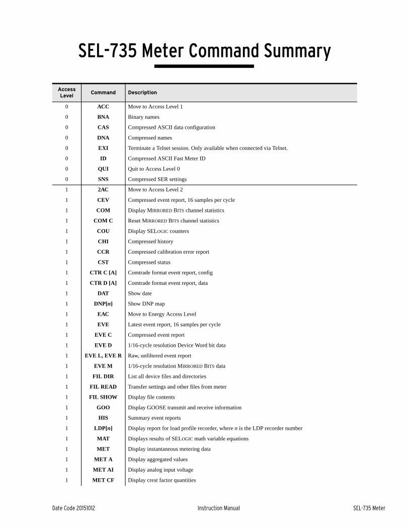
Date Code 20151012 Instruction Manual SEL-735 Meter
SEL-735 Meter Command Summary
Access Level
Command Description
0 ACC Move to Access Level 1
0 BNA Binary names
0 CAS Compressed ASCII data configuration
0 DNA Compressed names
0 EXI Terminate a Telnet session. Only available when connected via Telnet.
0 ID Compressed ASCII Fast Meter ID
0 QUI Quit to Access Level 0
0 SNS Compressed SER settings
1 2AC Move to Access Level 2
1 CEV Compressed event report, 16 samples per cycle
1 COM Display MIRRORED BITS channel statistics
1 COM C Reset MIRRORED BITS channel statistics
1 COU Display SELOGIC counters
1 CHI Compressed history
1 CCR Compressed calibration error report
1 CST Compressed status
1 CTR C [A] Comtrade format event report, config
1 CTR D [A] Comtrade format event report, data
1 DAT Show date
1 DNP[n] Show DNP map
1 EAC Move to Energy Access Level
1 EVE Latest event report, 16 samples per cycle
1 EVE C Compressed event report
1 EVE D 1/16-cycle resolution Device Word bit data
1 EVE L, EVE R Raw, unfiltered event report
1 EVE M 1/16-cycle resolution MIRRORED BITS data
1 FIL DIR List all device files and directories
1 FIL READ Transfer settings and other files from meter
1 FIL SHOW Display file contents
1 GOO Display GOOSE transmit and receive information
1 HIS Summary event reports
1 LDP[n] Display report for load profile recorder, where n is the LDP recorder number
1 MAT Displays results of SELOGIC math variable equations
1 MET Display instantaneous metering data
1 MET A Display aggregated values
1 MET AI Display analog input voltage
1 MET CF Display crest factor quantities

2
SEL-735 Meter Instruction Manual Date Code 20151012
SEL-735 Meter Command Summary
1 MET CFG Display configurable registers values
1 MET D Display compensated demand data
1 MET D P Display compensated peak demand data
1 MET D P U Display uncompensated peak demand data
1 MET D T Display the timestamps of the peak demands
1 MET D T U Display the timestamps of the uncompensated peak demands
1 MET D U Display uncompensated demand data
1 MET E Display energy data
1 MET FL Display flicker data
1 MET H Display harmonic data
1 MET L Display losses
1 MET M Display maximum and minimum values
1 MET PM Display Synchrophasor Data
1 MET PM time Display Synchrophasor Data at time time
1 MET PM HIS Display the most recently captured MET PM report
1 MET RMS Display rms metering data
1 QUI Quit to Access Level 0
1 SER Display Sequential Events Recorder records
1 SHO Display settings
1 SSI Display voltage sag/swell/interruption (VSSI) report
1 STA Display self-test status
1 STA E Display EEPROM messages
1 TAR Display Device Word bits
1 TIM Show time
1 TOG Resets NEWEVNT Device Word bit
1 TRI Trigger an event
1 VER Display version and configuration information
E DAT date Set date
E LDP[n] C Reset load profile recorder, where n is the LDP recorder number
E MET CF R Clear crest factor metering
E MET M R Clear max/min metering
E MET P R Clear peak demand metering
E QUI Quit to Access Level 0
E TIM time Set time
2 CAL Go to Access Level C
2 CON x Control remote bits x
2 DNP[n] Show DNP map
2 FIL WRITE Write setting files to the meter
2 FOR Change meter form
2 HIS C Clear event and history records
2 L_D Load new firmware
Access Level
Command Description

3
Date Code 20151012 Instruction Manual SEL-735 Meter
SEL-735 Meter Command Summary
2 LOO Initiate/clear MIRRORED BITS loopback
2 MET D R Clear demand metering
2 MET E R Reset energy metering
2 MET FL R Reset flicker metering quantities
2 MET P R Clear peak demand metering
2 MEM Display memory
2 PAR Display or modify the part number
2 PAS Set/show passwords
2 PUL Pulse output contact
2 QUI Quit to Access Level 0
2 R_S Restore factory settings
2 SER [R] Display or clear SER
2 SET Change settings
2 SSI C Clear SSI data (including SSI summary) from the meter
2 SSI R Reset SSI processing
2 SSI S Display SSI summary report
2 SSI T Trigger an event and store SSI data.
2 TES AGG Capture and display 10/12-cycle data
2 TEST DB A name value
Override analog label name with value in communications interface
2 TEST DB D name value
Override Device Word bit name with value in communications interface, where value = 0 or 1
2 TEST MODE Display Test Mode parameters
2 VER Display version and configuration information
SB BAU rate Set baud rate to 300, 1200, 2400, 4800, 9600, 19200, 38400 (57600 or 115200 if Port 2 or Port 3) bps.
SB BFI Display the SELBOOT version.
SB ERA Erase the existing firmware.
SB EXI Exit this program and restart the device.
SB FID Display the firmware identification (FID).
SB HEL Print a help list of commands.
SB REC Receive new firmware for the device using Xmodem.
Access Level
Command Description

This page intentionally left blank

Date Code 20151012 Instruction Manual SEL-735 Meter
SEL-735 Meter Command Summary
Access Level
Command Description
0 ACC Move to Access Level 1
0 BNA Binary names
0 CAS Compressed ASCII data configuration
0 DNA Compressed names
0 EXI Terminate a Telnet session. Only available when connected via Telnet.
0 ID Compressed ASCII Fast Meter ID
0 QUI Quit to Access Level 0
0 SNS Compressed SER settings
1 2AC Move to Access Level 2
1 CEV Compressed event report, 16 samples per cycle
1 COM Display MIRRORED BITS channel statistics
1 COM C Reset MIRRORED BITS channel statistics
1 COU Display SELOGIC counters
1 CHI Compressed history
1 CCR Compressed calibration error report
1 CST Compressed status
1 CTR C [A] Comtrade format event report, config
1 CTR D [A] Comtrade format event report, data
1 DAT Show date
1 DNP[n] Show DNP map
1 EAC Move to Energy Access Level
1 EVE Latest event report, 16 samples per cycle
1 EVE C Compressed event report
1 EVE D 1/16-cycle resolution Device Word bit data
1 EVE L, EVE R Raw, unfiltered event report
1 EVE M 1/16-cycle resolution MIRRORED BITS data
1 FIL DIR List all device files and directories
1 FIL READ Transfer settings and other files from meter
1 FIL SHOW Display file contents
1 GOO Display GOOSE transmit and receive information
1 HIS Summary event reports
1 LDP[n] Display report for load profile recorder, where n is the LDP recorder number
1 MAT Displays results of SELOGIC math variable equations
1 MET Display instantaneous metering data
1 MET A Display aggregated values
1 MET AI Display analog input voltage
1 MET CF Display crest factor quantities

2
SEL-735 Meter Instruction Manual Date Code 20151012
SEL-735 Meter Command Summary
1 MET CFG Display configurable registers values
1 MET D Display compensated demand data
1 MET D P Display compensated peak demand data
1 MET D P U Display uncompensated peak demand data
1 MET D T Display the timestamps of the peak demands
1 MET D T U Display the timestamps of the uncompensated peak demands
1 MET D U Display uncompensated demand data
1 MET E Display energy data
1 MET FL Display flicker data
1 MET H Display harmonic data
1 MET L Display losses
1 MET M Display maximum and minimum values
1 MET PM Display Synchrophasor Data
1 MET PM time Display Synchrophasor Data at time time
1 MET PM HIS Display the most recently captured MET PM report
1 MET RMS Display rms metering data
1 QUI Quit to Access Level 0
1 SER Display Sequential Events Recorder records
1 SHO Display settings
1 SSI Display voltage sag/swell/interruption (VSSI) report
1 STA Display self-test status
1 STA E Display EEPROM messages
1 TAR Display Device Word bits
1 TIM Show time
1 TOG Resets NEWEVNT Device Word bit
1 TRI Trigger an event
1 VER Display version and configuration information
E DAT date Set date
E LDP[n] C Reset load profile recorder, where n is the LDP recorder number
E MET CF R Clear crest factor metering
E MET M R Clear max/min metering
E MET P R Clear peak demand metering
E QUI Quit to Access Level 0
E TIM time Set time
2 CAL Go to Access Level C
2 CON x Control remote bits x
2 DNP[n] Show DNP map
2 FIL WRITE Write setting files to the meter
2 FOR Change meter form
2 HIS C Clear event and history records
2 L_D Load new firmware
Access Level
Command Description

3
Date Code 20151012 Instruction Manual SEL-735 Meter
SEL-735 Meter Command Summary
2 LOO Initiate/clear MIRRORED BITS loopback
2 MET D R Clear demand metering
2 MET E R Reset energy metering
2 MET FL R Reset flicker metering quantities
2 MET P R Clear peak demand metering
2 MEM Display memory
2 PAR Display or modify the part number
2 PAS Set/show passwords
2 PUL Pulse output contact
2 QUI Quit to Access Level 0
2 R_S Restore factory settings
2 SER [R] Display or clear SER
2 SET Change settings
2 SSI C Clear SSI data (including SSI summary) from the meter
2 SSI R Reset SSI processing
2 SSI S Display SSI summary report
2 SSI T Trigger an event and store SSI data.
2 TES AGG Capture and display 10/12-cycle data
2 TEST DB A name value
Override analog label name with value in communications interface
2 TEST DB D name value
Override Device Word bit name with value in communications interface, where value = 0 or 1
2 TEST MODE Display Test Mode parameters
2 VER Display version and configuration information
SB BAU rate Set baud rate to 300, 1200, 2400, 4800, 9600, 19200, 38400 (57600 or 115200 if Port 2 or Port 3) bps.
SB BFI Display the SELBOOT version.
SB ERA Erase the existing firmware.
SB EXI Exit this program and restart the device.
SB FID Display the firmware identification (FID).
SB HEL Print a help list of commands.
SB REC Receive new firmware for the device using Xmodem.
Access Level
Command Description

This page intentionally left blank