Seiten 9-12 Aus 249 the Influence of Filter Type and Gating System
7
07 T h e i n f l u e n c e o f f i l t e r t y p e a n d g a t i n g s y s t e d e s i g n o n t h e m a c h i n a b i l i t y o f v r t i c a l l y p a r t e d g r e y i r o n c a s t i n g s This report describes the effects that well established different filter types and running system designs have on the machinability of vertically parted moulded castings. Foundries with vertically parted moulding lines normally want to avoid applying filters because their use can, in some cases, lead to extended cycle times. Consequently, the use of filters has been relatively modest. Recently, however, increasing quality demands has led to a renewed interest from foundries. This paper will deal with grey iron castings such as brake discs, brake drums and c lutch plates. The results were obtained from studies, theoretical expertise and foundry field trials. The paper aims to demonstrate that problematic issues regarding filter use on vertically parted moulds can be overcome whilst simultaneously improving the properties of the castings. The influence of filter t ype and gat ing s ys t em design on the machinability of vertically parted grey iron castings Introduction Filter location options on vert ically parted moulds If the pattern plate has two or more levels, there is often no option other than to locate the filter in the upper part of the mould. A filter in this position provides a mechanism for slag retention, but much of the flow modification benefits will be lost due to uncontrolled flow of the metal after the filter. If the filter is located in the bottom of the mould, the increased ferrostatic pressure can result in higher metal velocity through the filter. This increases the risk of slag being forced through the filter and into the casting cavity. With these problems in mind, the design of pouring systems for vertically parted moulds was revised. The following modifications were found to be helpful in ensuring that moulds fill in a non-turbulent manner. Basics For bottom gated mould cavities, the system choke should be located in the downsprue after the filter. The cross-sectional areas of the runners and ingates should then be increased to reduce the velocity of the metal as it enters the mould cavity. For side-gated moulds, the choke can again be located in the downsprue. The ingate cross- sectional area should then be increased to reduce the velocity of the metal. If the casting is top gated, the choke Figure 1 Standard gating system Figure 2 Gating system with cross-over and inclined downsprue must be located at the ingates otherwise the runner system cannot completely fill especially during the early stages of the pour. Sprue cross-over A cross-over describes a design in which the downsprue “crosses over” from the swing plate side to the ram plate side before the filter. The advantage is that the liquid metal does not impinge directly on the filter and a slag chamber can be located directly in front it. This is a technique that is routinely used on horizontally parted moulds. Another advantage of this technique is that the runner fills more quickly and reduces the likelihood of gas entrainment. Inclined downsprue A technique to reduce the velocity of the metal is to use inclined downsprues with an inclination of about 10 to 15°. This technique will significantly reduce the velocity of the liquid metal (figures 1 and 2). Runner system design options for vert ically parted moulds i ncluding filters
-
Upload
mecaunidos7771 -
Category
Documents
-
view
218 -
download
0
Transcript of Seiten 9-12 Aus 249 the Influence of Filter Type and Gating System

7/28/2019 Seiten 9-12 Aus 249 the Influence of Filter Type and Gating System
http://slidepdf.com/reader/full/seiten-9-12-aus-249-the-influence-of-filter-type-and-gating-system 1/6
07
T h ei nf l u
en
c e of f i l t er
t y p e an
d g a t i n g s y s t em d
e si gn
o
n t h em
a ch i n
a b i l i t y
of v
er t i c al l y
p ar t e
d gr e
yi r on
c a s t i n g s
This report describes the effects that well establisheddifferent filter types and running system designs have onthe machinability of vertically parted moulded castings.Foundries with vertically parted moulding lines normallywant to avoid applying filters because their use can, insome cases, lead to extended cycle times. Consequently,the use of filters has been relatively modest. Recently,however, increasing quality demands has led to arenewed interest from foundries.
This paper will deal with grey iron castings such as brakediscs, brake drums and c lutch plates. The results wereobtained from studies, theoretical expertise and foundryfield trials. The paper aims to demonstrate thatproblematic issues regarding filter use on verticallyparted moulds can be overcome whilst simultaneouslyimproving the properties of the castings.
The inf luence of f ilt er type and gat ing systemdesign on the machinability of vertically partedgrey iron castings
Introduction
Filter location options on verticallyparted moulds
If the pattern plate has two or more levels, there is oftenno option other than to locate the filter in the upper partof the mould. A filter in this position provides amechanism for slag retention, but much of the flowmodification benefits will be lost due to uncontrolled flowof the metal after the filter.
If the filter is located in the bottom of the mould, theincreased ferrostatic pressure can result in higher metalvelocity through the filter. This increases the risk of slagbeing forced through the filter and into the casting cavity.
With these problems in mind, the design of pouringsystems for vertically parted moulds was revised. Thefollowing modifications were found to be helpful inensuring that moulds fill in a non-turbulent manner.
BasicsFor bottom gated mould cavities, the system chokeshould be located in the downsprue after the filter. Thecross-sectional areas of the runners and ingates shouldthen be increased to reduce the velocity of the metal as itenters the mould cavity. For side-gated moulds, the chokecan again be located in the downsprue. The ingate cross-
sectional area should then be increased to reduce thevelocity of the metal. If the casting is top gated, the choke
Figure 1 Standard gating system
Figure 2 Gating system with cross-over and inclined downsprue
must be located at the ingates otherwise the runnersystem cannot completely fill especially during the earlystages of the pour.
Sprue cross-overA cross-over describes a design in which the downsprue“crosses over” from the swing plate side to the ram plateside before the filter. The advantage is that the liquidmetal does not impinge directly on the filter and a slagchamber can be located directly in front it. This is atechnique that is routinely used on horizontally partedmoulds. Another advantage of this technique is that therunner fills more quickly and reduces the likelihood of gas
entrainment.
Inclined downsprueA technique to reduce the velocity of the metal is to useinclined downsprues with an inclination of about 10 to15°. This technique will significantly reduce the velocity of the liquid metal (figures 1 and 2).
Runner system design options forvertically parted moulds including filters

7/28/2019 Seiten 9-12 Aus 249 the Influence of Filter Type and Gating System
http://slidepdf.com/reader/full/seiten-9-12-aus-249-the-influence-of-filter-type-and-gating-system 2/6
8
Figure 3 The metal hits directly against the mould cod
Figure 4 The metal enters the mould cavity at slower speed anddoes not hit the mould cod directly
The effects on the mould filling can be dramatic,
especially during the critical first few seconds when liquidmetal enters the mould cavity (figures 3 and 4).
Design of the ingatesCastings such as brake discs and drums are almost
exclusively bottom-gated and the behaviour of the metalas it enters the mould cavity is critical. Back pressurewill not be present at this point and the metal can enterthe mould cavity as a “fountain”. This can cause defectsdue to re-oxidation and sand erosion. To minimise thiseffect, the flow direction of the metal can be interruptedby the incorporation of an ingate with a 45º angle(figures 5 and 6).
Machinability trialsTo test some of the above theories, a machinability studywas conducted in co-operation with one of the leadingEuropean DISA Foundries and a US university.Machinability is related to many factors and the effectsmay vary from foundry to foundry, and as such, this study
can only provide a rough overview on the various factorsthat may have an influence.
An unventilated brake disk was chosen for the trials. Thiswas done in order to avoid effects related to thepositioning of cores.
Trial detailsTrials were conducted using a pressed device with a holediameter of 1.5mm, extruded device in 300 csi, and 30ppiSEDEX* filters. All filters were 50x50x15mm.
Figure 5 Inclined ingates
Figure 6 Ingates with 45° angle

7/28/2019 Seiten 9-12 Aus 249 the Influence of Filter Type and Gating System
http://slidepdf.com/reader/full/seiten-9-12-aus-249-the-influence-of-filter-type-and-gating-system 3/6
09
T h ei nf l u
en
c e of f i l t er
t y p e an
d g a t i n g s y s t em d
e si gn
o
n t h em
a ch i n
a b i l i t y
of v
er t i c al l y
p ar t e
d gr e
yi r on
c a s t i n g s
The following pouring systems were tested. These were
designed to test the concepts discussed earlier.
1. Running system without a filter. Ingate controlled withslag trap. The pattern layout for these trials wasprovided by the foundry
2. The same system as 1, but without slag trap
3. Filter positioned in the upper part of the mould,downsprue controlled (figure 7)
a) Pressed device with 1.5mm hole diameterb) Extruded device 300 csic) SEDEX 30 ppi filter
4. Filter positioned at the bottom of the mould,downsprue controlled (figure 8)
a) Pressed device with 1.5mm hole diameterb) Extruded device 300 csic) SEDEX 30 ppi filter
5. Filter positioned at the bottom of the mould withadditional cross-over, downsprue controlled (figure 9)
a) Pressed device with 1.5mm hole diameterb) Extruded device 300 csic) SEDEX 30 ppi filter
All trials were conducted during a single morning toensure conditions were as consistent as possible. Witheach layout approximately 100 castings were made and,after finishing, the surface defects were counted. Theaverage amount of surface defects on the castings wasthen calculated.
Table 1 shows the results:
Figure 9 Gating system with filter at the bottom of the mouldand cross-over
Figure 8 Gating system with filter at thebottom of the mould
Figure 7 Gating system with filter in theupper part of the mould
System Pouring Pouring Number Surface Surface Defects AverageTemp Time of Defects Defects TOTAL Defects[°C] [s] Castings Side 1 Side 2 per
Casting
1 1410 10 80 278 178 456 5.72 1405 7.5 90 583 636 1219 13.5
3a 1410 6.0 86 215 303 518 6.03b 1417 5.4 72 177 245 422 5.93c 1408 5.4 92 285 341 626 6.84a 1403 5.0 79 56 49 105 1.34b 1402 5.2 85 33 24 57 0.74c 1411 5.4 82 22 26 48 0.65a 1406 5.6 83 46 79 125 1.55b 1404 5.6 85 19 11 30 0.45c 1404 5.2 85 13 10 23 0.3
Table 1
❑ The redesigned gating (incorporating a filter)significantly reduced the pouring time
❑ The design and the connection to the slag chamber intrial 1, does not allow faster pouring times withoutsustainable quality losses
❑ The position of the filter greatly influences theaverage amount of surface defects per casting. Thiscould be a reason why many foundries do not noticeany scrap reduction when filters are placed in anineffective position. Additionally, the possibility of
reducing pouring times is often not considered
❑ The best result was achieved with cross-over and theSEDEX foam filter.
Trial observations

7/28/2019 Seiten 9-12 Aus 249 the Influence of Filter Type and Gating System
http://slidepdf.com/reader/full/seiten-9-12-aus-249-the-influence-of-filter-type-and-gating-system 4/6
0
After the evaluation, the machinability of
the castings was tested. Because of theconsiderable high costs involved only 4systems out of 11 were machined. Theywere then compared to the castings madeby pouring systems without a filter andslag trap.
For the machinability study metal toolswere used. Surface speed was constant at1500 SFM (7.62m/s).
Machining procedure:❑ The remains of the ingates were
removed and these areas weremachined
❑ The brake disc was then mounted onthe CNC machine and machined fromthe inside to the outside as describedbelow:
- 2 slices of 0.5mm each weremachined off. These slices willhereafter be referred to as "SKIN".After each cut the wear of thetools was measured and recorded
- 4 slices of 0.5mm each weremachined off. These slices willhereafter be referred to as "BULK.Again, the wear of the tools wasagain measured and recorded.
This was repeated until a maximum toolwear of 0.025 inch was attained for "SKIN"and for "BULK". Three tools were appliedper batch (figure 10).
The machinability index is defined as tool wear in inches (in.) for a
certain amount of cut metal in cubic inches (in³).
The results were recorded and graphed as described in the graph below(figure 11).
Figure 12 - 15 present the results of various gating and filter types.
Figure 10 CNC device with tool
Figure 11
Comments on the graph: • The x-axis shows the amount of cut metal in cubic inches
• The y-axis shows the tool wear in inches
• As reference point a tool wear of 0.020 inches was set and incomparison the amount of cut metal was identified
• The dotted line shows the variation (standard deviation)
• The steeper the straight line the worse the machinability.
End
Start
Metal tool

7/28/2019 Seiten 9-12 Aus 249 the Influence of Filter Type and Gating System
http://slidepdf.com/reader/full/seiten-9-12-aus-249-the-influence-of-filter-type-and-gating-system 5/6
11
T h ei nf l u
en
c e of f i l t er
t y p e an
d g a t i n g s y s t em d
e si gn
o
n t h em
a ch i n
a b i l i t y
of v
er t i c al l y
p ar t e
d gr e
yi r on
c a s t i n g s
Figure 12 Gating systems without filter and slag trap
Skin Bulk
Figure 13 Gating system with pressed device (1.5mm hole diameter) and cross-over
Skin Bulk
Figure 14 Gating systems with extruded device (300csi) and cross-over
Skin Bulk
Figure 15 Gating system with SEDEX 50x50x15/30ppi and cross-over
Skin Bulk
0.025
0.020
0.015
0.010
0.005
0.0000 5 10 15 20 25 30 35 40 45 50
Volume of Metal Removed (in 3)
0.025
0.020
0.015
0.010
0.005
0.0000 5 10 15 20 25 30 35 40 45 50
Volume of Metal Removed (in 3)
0.025
0.020
0.015
0.010
0.005
0.0000 5 10 15 20 25 30 35 40 45 50
Volume of Metal Removed (in 3)
0.025
0.020
0.015
0.010
0.005
0.0000 5 10 15 20 25 30 35 40 45 50
Volume of Metal Removed (in 3)
0.025
0.020
0.015
0.010
0.005
0.0000 5 10 15 20 25 30 35 40 45 50
Volume of Metal Removed (in 3)
0.025
0.020
0.015
0.010
0.005
0.0000 5 10 15 20 25 30 35 40 45 50
Volume of Metal Removed (in 3)
0.025
0.020
0.015
0.010
0.005
0.0000 5 10 15 20 25 30 35 40 45 50
Volume of Metal Removed (in 3)
0.025
0.020
0.015
0.010
0.005
0.0000 5 10 15 20 25 30 35 40 45 50
Volume of Metal Removed (in 3)
10,0
7/28/2019 Seiten 9-12 Aus 249 the Influence of Filter Type and Gating System
http://slidepdf.com/reader/full/seiten-9-12-aus-249-the-influence-of-filter-type-and-gating-system 6/6
2
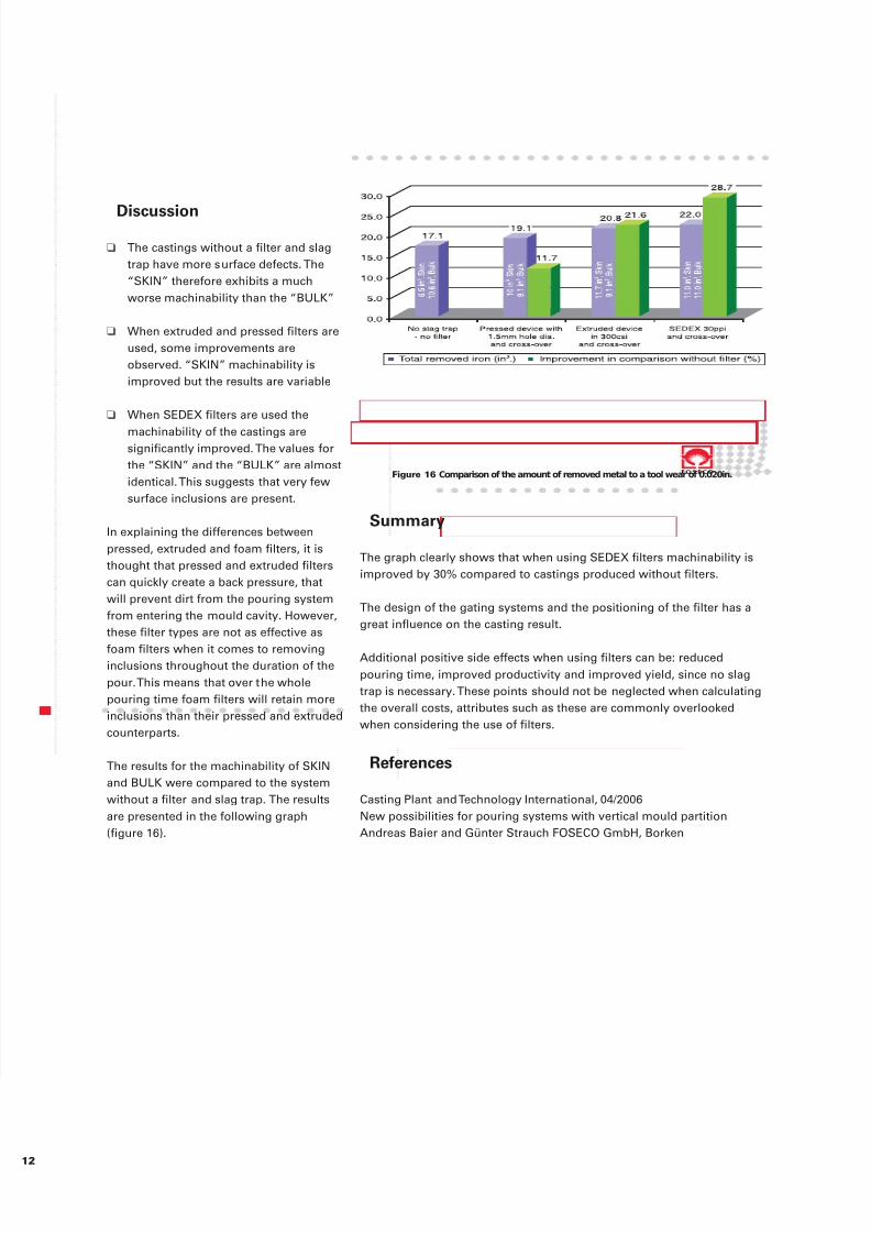
Figure 16 Comparison of the amount of removed metal to a tool wear of 0.020in.
Summary
❑ The castings without a filter and slagtrap have more surface defects. The“SKIN” therefore exhibits a muchworse machinability than the “BULK”
❑ When extruded and pressed filters areused, some improvements areobserved. “SKIN” machinability isimproved but the results are variable
❑ When SEDEX filters are used the
machinability of the castings aresignificantly improved. The values forthe “SKIN” and the “BULK” are almostidentical. This suggests that very fewsurface inclusions are present.
In explaining the differences betweenpressed, extruded and foam filters, it isthought that pressed and extruded filterscan quickly create a back pressure, thatwill prevent dirt from the pouring systemfrom entering the mould cavity. However,these filter types are not as effective as
foam filters when it comes to removinginclusions throughout the duration of thepour. This means that over the wholepouring time foam filters will retain moreinclusions than their pressed and extrudedcounterparts.
The results for the machinability of SKINand BULK were compared to the systemwithout a filter and slag trap. The resultsare presented in the following graph(figure 16).
Discussion
The graph clearly shows that when using SEDEX filters machinability isimproved by 30% compared to castings produced without filters.
The design of the gating systems and the positioning of the filter has agreat influence on the casting result.
Additional positive side effects when using filters can be: reducedpouring time, improved productivity and improved yield, since no slagtrap is necessary. These points should not be neglected when calculatingthe overall costs, attributes such as these are commonly overlookedwhen considering the use of filters.
Casting Plant and Technology International, 04/2006New possibilities for pouring systems with vertical mould partitionAndreas Baier and Günter Strauch FOSECO GmbH, Borken
References