Seismic Strengthening of Reinforced Concrete …...Seismic Strengthening of Reinforced Concrete...
24
16 Seismic Strengthening of Reinforced Concrete Buildings Hasan Kaplan and Salih Yılmaz Pamukkale University, Department of Civil Engineering Turkey 1. Introduction Many buildings have either collapsed or experienced different levels of damage during past earthquakes. Several investigations have been carried out on buildings that were damaged by earthquakes. Low-quality concrete, poor confinement of the end regions, weak column-strong beam behavior, short column behavior, inadequate splice lengths and improper hooks of the stirrups were some of the important structural deficiencies (Yakut et al., 2005). Most of those buildings were constructed before the introduction of modern building codes. They usually cannot provide the required ductility, lateral stiffness and strength, which are definitely lower than the limits imposed by the modern building codes (Kaplan et al., 2011). Due to low lateral stiffness and strength, vulnerable structures are subjected to large displacement demands, which cannot be met adequately as they have low ductility. One of the first known examples of strengthening is the strengthening of Hagia Sophia by Sinan the Architect in 1573. With an insight casting light on the modern era, Sinan built buttress type shear walls around the mosque in order to reduce horizontal displacements of the building. When looked at the scientific studies that were carried out on this field, it is seen a research process started in 1950s (Whitney et al., 1955). In those years, infill wall tests which had started to be performed on single storey reinforced concrete frames continued with several structural types and strengthening methods. Deficiencies that emerge in reinforced concrete buildings in terms of stiffness, strength, ductility and redundancy led to studies intended to strengthen buildings against earthquakes. The strengthening methods used today are intended to improve one or some of the behavioral characteristics of buildings listed above. Methods for the strengthening of buildings may basically be categorized into two main groups: System based strengthening and member based strengthening (Moehle, 2000). In the system based strengthening methods, a structural system is modified by adding members such as reinforced concrete shear walls, mainly improving the strength and stiffness characteristics of the system (Jirsa & Kreger, 1989; Albanesi et al., 2006). As to the member based strengthening methods, it is aimed at ensuring an improvement in the ductility of a system by means of enhancements made to those members with inadequate capacity or ductility. In these methods, it can be considered that there are no significant changes occurring in strength and stiffness characteristics of the load-bearing system. www.intechopen.com
Transcript of Seismic Strengthening of Reinforced Concrete …...Seismic Strengthening of Reinforced Concrete...

16
Seismic Strengthening of Reinforced Concrete Buildings
Hasan Kaplan and Salih Yılmaz Pamukkale University, Department of Civil Engineering
Turkey
1. Introduction
Many buildings have either collapsed or experienced different levels of damage during past earthquakes. Several investigations have been carried out on buildings that were damaged by earthquakes. Low-quality concrete, poor confinement of the end regions, weak column-strong beam behavior, short column behavior, inadequate splice lengths and improper hooks of the stirrups were some of the important structural deficiencies (Yakut et al., 2005). Most of those buildings were constructed before the introduction of modern building codes. They usually cannot provide the required ductility, lateral stiffness and strength, which are definitely lower than the limits imposed by the modern building codes (Kaplan et al., 2011). Due to low lateral stiffness and strength, vulnerable structures are subjected to large displacement demands, which cannot be met adequately as they have low ductility. One of the first known examples of strengthening is the strengthening of Hagia Sophia by Sinan the Architect in 1573. With an insight casting light on the modern era, Sinan built buttress type shear walls around the mosque in order to reduce horizontal displacements of the building. When looked at the scientific studies that were carried out on this field, it is seen a research process started in 1950s (Whitney et al., 1955). In those years, infill wall tests which had started to be performed on single storey reinforced concrete frames continued with several structural types and strengthening methods. Deficiencies that emerge in reinforced concrete buildings in terms of stiffness, strength, ductility and redundancy led to studies intended to strengthen buildings against earthquakes. The strengthening methods used today are intended to improve one or some of the behavioral characteristics of buildings listed above. Methods for the strengthening of buildings may basically be categorized into two main groups: System based strengthening and member based strengthening (Moehle, 2000). In the system based strengthening methods, a structural system is modified by adding members such as reinforced concrete shear walls, mainly improving the strength and stiffness characteristics of the system (Jirsa & Kreger, 1989; Albanesi et al., 2006). As to the member based strengthening methods, it is aimed at ensuring an improvement in the ductility of a system by means of enhancements made to those members with inadequate capacity or ductility. In these methods, it can be considered that there are no significant changes occurring in strength and stiffness characteristics of the load-bearing system.
www.intechopen.com
Earthquake-Resistant Structures – Design, Assessment and Rehabilitation
408
Fig. 1. Hagia Sophia is strengthened with external buttress type walls by Sinan in 1573.
2. Design philosophy for strengthening
During earthquake motions, deformations take place across the elements of the load-bearing system as a result of the response of buildings to the ground motion. As a consequence of these deformations, internal forces develop across the elements of the load-bearing system and a displacement behavior appears across the building. The resultant displacement demand varies depending on the stiffness and mass of the building. In general, buildings with higher stiffness and lower mass have smaller horizontal displacements demands. On the contrary, displacement demands are to increase. On the other hand, each building has a specific displacement capacity. In other words, the amount of horizontal displacement that a building can afford without collapsing is limited. The purpose of strengthening methods is to ensure that the displacement demand of a building is to be kept below its displacement capacity (Yılmaz et al., 2011). This can mainly be achieved by reducing expected displacement demand of the structure during the strong motion or improving the displacement capacity of the structure. In the system strengthening, new elements are added to a building to enhance its global stiffness. With an increase in the stiffness, the natural period of vibration of the building is to decrease. This, in turn, will result in a decrease in the amount of horizontal displacement that must be achieved by the building to resist earthquakes. When the building has enough stiffness, it will no longer able to achieve the amount of displacement which would cause it to collapse. Moreover, addition of new members to the building shall mostly increase the horizontal load
www.intechopen.com

Seismic Strengthening of Reinforced Concrete Buildings
409
capacity of the building as well (Canbay et al., 2003). The increased capacity will therefore require greater ground motions to allow the building to develop a yielding behavior. Thus, it can be said that the system strengthening does not only prevent collapsing but also delays structural damages. More clearly, the damage level of a building which is expected to sustain significant damages during a medium intensity earthquake may be reduced to minimum levels when it is strengthened by system strengthening techniques. The element strengthening is a method based on the reinforcement of inadequate elements triggering the loss of stability due to the sustained damages without undertaking major changes in the load-bearing system of the building. In this method, negligible changes take place in the characteristics of a building such as stiffness and mass since no significant changes are made to the load-bearing system. Therefore, it must be considered that there will be no significant changes in the displacement demand after the member strengthening.
Fig. 2. Change in the displacement demand and capacity of the structure after strengthening
3. System based strengthening techniques
Most of the strengthening strategies have recently been based on global strengthening schemes as per which the structure is usually strengthened for limiting lateral displacements in order to compensate the low ductility (Sonuvar et al., 2004). In these methods causing a change in the global behavior of a building, as explained above, a behavioral change takes place when new members are added to the building. For a building which is currently used, it is important that the new members which are to be added to the structure are few in number and they are designed to ensure a significant increase in the load capacity and stiffness of the structure. It is well known by construction engineers that this target may most easily and economically be achieved through reinforced concrete and steel shear walls. Shear walls that are to be added to the building can be designed in the form of infill shear wall (Higashi et al., 1982) or external shear wall (Kaplan et al., 2009). Below are presented some of the most frequently applied system based strengthening methods.
www.intechopen.com
Earthquake-Resistant Structures – Design, Assessment and Rehabilitation
410
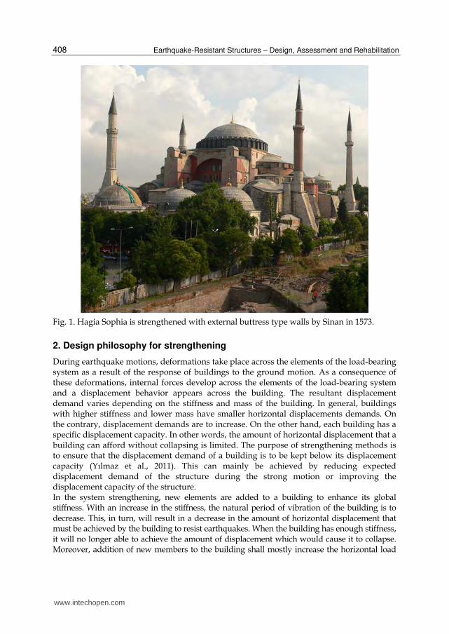
3.1 Infill shear walls Among the global strengthening methods, addition of RC infill is the most popular one. Many researchers have focused on the addition of infill RC walls and found that the installation of RC infill walls greatly improves lateral load capacity and stiffness of the structure. Even in cases of application to damaged buildings, the infill method can yield satisfactory results (Canbay et al., 2003; Sonuvar et al., 2004). In the strengthening method with infill walls, the existing partition walls in the building are removed and high strength reinforced concrete shear walls are built instead (Figure 3). In such a strengthening application, the shear walls bear majority of the earthquake loads and limits the displacement behavior of the building while the frame system resists very low amounts of the earthquake loads. Reinforced concrete infill walls can also be used as partial walls and wing walls (Higashi et al., 1982; Bush et al., 1992). Door and window openings may also be provided in these walls to allow the building to deliver its architectural functions although they reduce stiffness and strength of the wall. In such applications preventing the construction of infill walls in the form of a full-fill wall, many experimental studies indicated that these walls develop more brittle damages compared to full-fill walls.
Fig. 3. Infill wall application in an RC building
As seen in Figure 4, columns of the existing building constitute the end regions of infill walls. Well confined end regions of reinforced concrete walls are considerably important in terms of the ductility of the wall. However, at the end regions of the strengthening walls, there generally exist inadequately confined columns with lower concrete strength. In that case, the end region must be confined in order to enhance ductility of the wall. Figure 4 presents various alternatives for confining end zones. Confined end region can be both made by jacketing of the existing column and can also be formed in the infill wall. If confinement and material characteristics of the existing columns are relatively good, the
www.intechopen.com

Seismic Strengthening of Reinforced Concrete Buildings
411
confined end region may be provided in the infill wall (TEC, 2007). In case the characteristics of end column are poor, it should be preferred to jacket the existing column.
Fig. 4. Formation of the end zones in full or partial shear walls
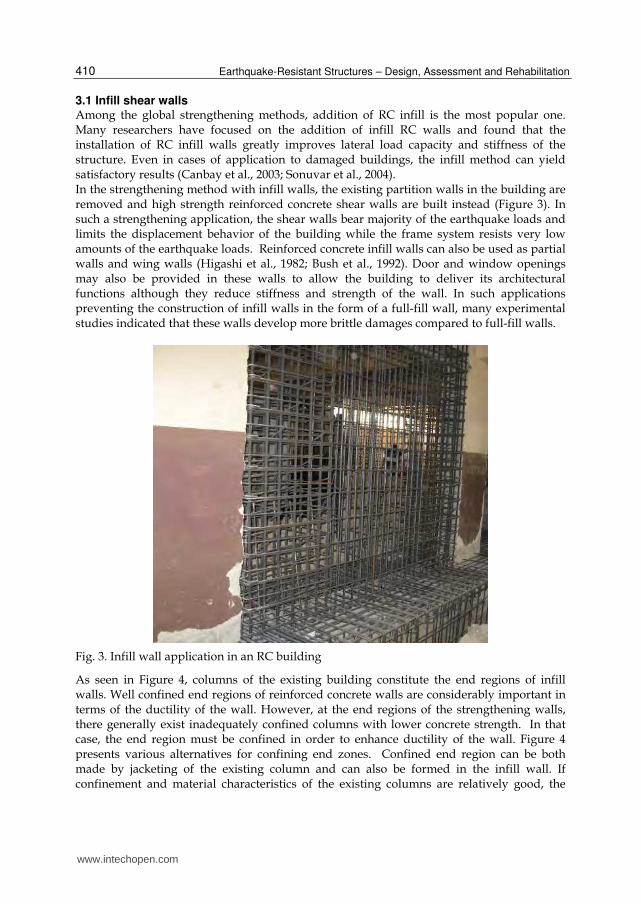
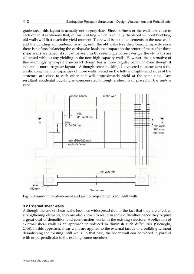
Minimum reinforcement and anchor requirements for infill walls are given in Figure 5. It is also considerably important to ensure the continuity of longitudinal reinforcement in a manner that allows the wall to achieve an adequate moment capacity. Reinforcement continuity can be maintained by means of continuous anchors which are installed across beams and extended to both storeys. Anchors that are both installed across the foundation and the beams and fastened to the longitudinal reinforcements must have an enough lap splice length and embedment depth. If beam height is big, it would be difficult, or even impossible to drill the beam along its height and to install anchors. In such cases, wall can be constructed by breaking the beam or the longitudinal reinforcements can be placed on the sides of the beam by making the infill walls wider than the beam. In that case, anchored crossties must be installed on the lateral faces of the beam in order to restrict the buckling length of the reinforcement by fastening to the lateral face of the beam. In Figure 6, it is seen that with such anchors, there is a decrease in the buckling length of the longitudinal reinforcement extending along the sides of a beam. Anchored crossties can either be installed on both sides of a beam or be installed on each face separately. Reinforced concrete walls to be added to the structure must be placed in a manner that it is not caused torsional effects on the structure and irregularities in the structure are eliminated, as observed in the design of new buildings. Some appropriate and inappropriate shear wall layouts are presented in Figure 7. The added walls must be regularly distributed across the plan. Unlike the design of existing building, a special example for strengthening is seen in Figure 7, at the bottommost. Although new walls are seemingly added in a symmetric and regular way to a building which have 2 irregular walls made from S220
www.intechopen.com
Earthquake-Resistant Structures – Design, Assessment and Rehabilitation
412
grade steel, this layout is actually not appropriate. Since stiffness of the walls are close to each other, it is obvious that, in this building which is initially displaced without buckling, old walls will first reach the yield moment. There will be no enhancements in the new walls and the building will undergo twisting until the old walls lose their bearing capacity since there is no force balancing the earthquake loads that impact on the center of mass after these shear walls are failed. As it can be seen, in this seemingly correct design, the old walls are collapsed without any yielding in the new high capacity walls. However, the alternative of this seemingly appropriate incorrect design has a more regular behavior even though it exhibits a more irregular layout. Although some buckling is expected to occur across the elastic zone, the total capacities of those walls placed on the left- and right-hand sides of the structure are close to each other and will approximately yield at the same time. Any resultant accidental buckling is compensated through a shear wall placed in the middle zone.
Fig. 5. Minimum reinforcement and anchor requirements for infill walls
3.2 External shear walls Although the use of shear walls becomes widespread due to the fact that they are effective strengthening elements, they are also known to result in some difficulties hence they require a great deal of demolition and construction works in the existing structure. Application of external shear walls is an approach introduced to diminish such difficulties (Sucuoglu, 2006). In this approach, shear walls are applied to the external facade of a building without demolishing the existing infill walls. In that case, the shear wall can be placed in parallel with or perpendicular to the existing frame members.
www.intechopen.com

Seismic Strengthening of Reinforced Concrete Buildings
413
Fig. 6. Wide infill walls and anchored crossties confining the longitudinal reinforcements
In case the shear walls are located perpendicular to the building façade (Kaltakci et al., 2008), large openings are needed in the building facade. The shear walls installed function like a buttress. In cases where pile foundation is not applied for the shear wall foundation, such shear walls are effective in only one direction. In order to create a positive effect on earthquake resistance of the building, they must be installed at opposite facades. This increases the required amount of shear walls and costs. For all these reasons, external shear walls that located perpendicular to the external facade are not preferred in the application. The more preferred form of the external shear walls is the application where they are installed in parallel with the building façade (Yılmaz et al., 2010c, 2011). An example of the application of a shear wall located in parallel with the building facade is seen in Figure 8. Design and application of external shear walls are easier compared to that of infill walls. End zones of shear walls can be detailed in itself. These shear walls may also be manufactured as prefabricated panels and assembled in place (Yılmaz et al., 2010a, 2011; Kaplan et al., 2009). Contrary to various advantages of external shear walls, there is a significant difference between external shear walls and infill shear walls. External shear walls shall not make a positive contribution to the frame strength when anchors connecting the external shear walls to the existing frame are damaged. However, even if infill shear walls are designed inadequately or applied incorrectly, it is apparent that they will have a bracing effect on the frame (Ohmura et al., 2006). In reinforced concrete design of external shear walls, it should be conformed to those guidelines that must be considered when designing reinforced concrete shear walls. What has importance is to correctly connect the external shear wall to the existing frame (Yılmaz, et al., 2010a, 2011). Although there is no methods for this provided in the applicable codes, from the experimental studies carried out by the authors, it was found that anchors can exhibit adequate performance when the design anchor shear force is determined in accordance with the capacity design principles.
www.intechopen.com

Earthquake-Resistant Structures – Design, Assessment and Rehabilitation
414
Fig. 7. Inappropriate and appropriate shear wall layouts
www.intechopen.com

Seismic Strengthening of Reinforced Concrete Buildings
415
Fig. 8. An external shear wall strengthened building
The load transfer the external shear wall and the existing structure by the external shear wall anchors is schematically presented in Figure 9. To design anchors of the external shear wall, it is first determined the shear wall’s ultimate moment capacity (Mp). The design shear force of the anchors applied to beams at the storey level, Vab is calculated for ith storey by the equation 1 given below. For calculations made for the last storey, it is taken that Vd,i+1=0. This force will give the anchor force required to transfer the necessary shear force to the shear wall at the relevant storey to allow the shear wall to reach its capacity at its bottom.
, , , 1( )p
ab i d i d id
MV V V
M (1)
Fig. 9. Load transfer between the structure and external shear walls by anchors
www.intechopen.com

Earthquake-Resistant Structures – Design, Assessment and Rehabilitation
416
After the storey anchor design obtained, contribution of the anchors to the shear wall moment capacity is established. When Mab moment created by Vab forces at the bottom of shear wall is subtracted from the ultimate bearing capacity of the shear wall, the residual moment (Mac) obtained is expected to be carried by a force couple which is to be created by the anchors installed in the columns (Equation 3).
,1
n
ab ab i ii
M V H
(2)
ac p abM M M (3)
Experimental studies carried out indicated that an increase in the design anchor shear force for the last storey by 25 to 30 % has positive effects in terms of behavior (Yılmaz, et al., 2010a). In general, anchor damage which is to be created at the top storey subjected to the maximum anchor shear force results in a significant loss in the bearing capacity of the shear wall and causes the anchors at the lower storeys to be damaged or leads to serious damages at the top storey level (Figure 10).
Fig. 10. A damaged upper storey due to poor anchor design
www.intechopen.com
Seismic Strengthening of Reinforced Concrete Buildings
417
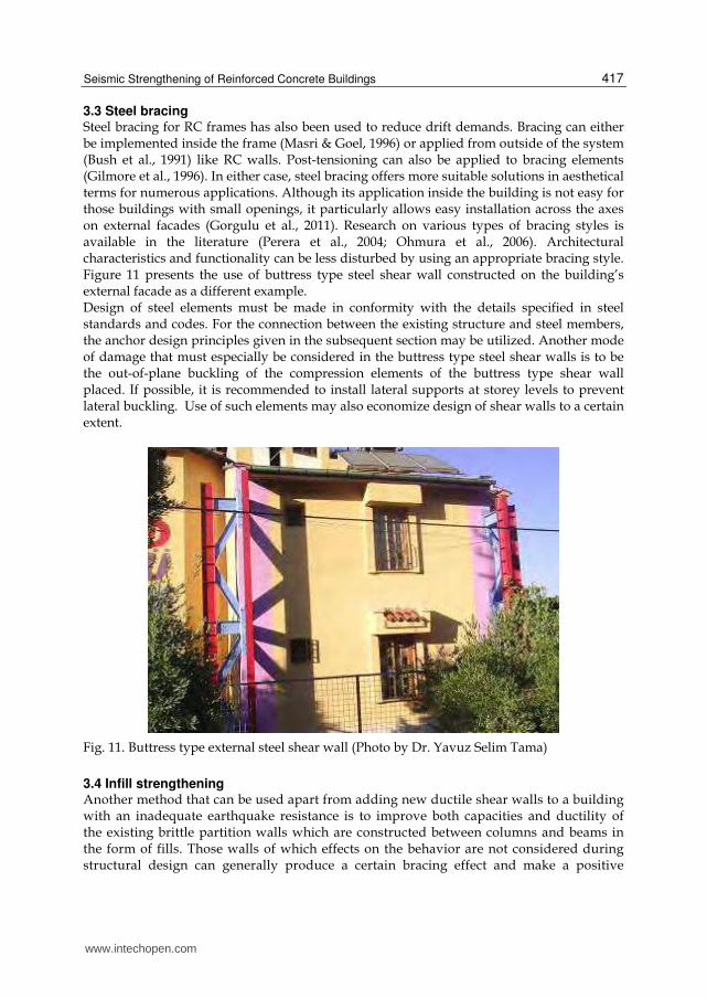
3.3 Steel bracing Steel bracing for RC frames has also been used to reduce drift demands. Bracing can either be implemented inside the frame (Masri & Goel, 1996) or applied from outside of the system (Bush et al., 1991) like RC walls. Post-tensioning can also be applied to bracing elements (Gilmore et al., 1996). In either case, steel bracing offers more suitable solutions in aesthetical terms for numerous applications. Although its application inside the building is not easy for those buildings with small openings, it particularly allows easy installation across the axes on external facades (Gorgulu et al., 2011). Research on various types of bracing styles is available in the literature (Perera et al., 2004; Ohmura et al., 2006). Architectural characteristics and functionality can be less disturbed by using an appropriate bracing style. Figure 11 presents the use of buttress type steel shear wall constructed on the building’s external facade as a different example. Design of steel elements must be made in conformity with the details specified in steel standards and codes. For the connection between the existing structure and steel members, the anchor design principles given in the subsequent section may be utilized. Another mode of damage that must especially be considered in the buttress type steel shear walls is to be the out-of-plane buckling of the compression elements of the buttress type shear wall placed. If possible, it is recommended to install lateral supports at storey levels to prevent lateral buckling. Use of such elements may also economize design of shear walls to a certain extent.
Fig. 11. Buttress type external steel shear wall (Photo by Dr. Yavuz Selim Tama)
3.4 Infill strengthening Another method that can be used apart from adding new ductile shear walls to a building with an inadequate earthquake resistance is to improve both capacities and ductility of the existing brittle partition walls which are constructed between columns and beams in the form of fills. Those walls of which effects on the behavior are not considered during structural design can generally produce a certain bracing effect and make a positive
www.intechopen.com
Earthquake-Resistant Structures – Design, Assessment and Rehabilitation
418
contribution to the behavior. There are too many uncertainties regarding the behavior of these members and they are not likely to produce a desired bracing effect at all times. Partition walls may also lead to brittle damages across the surrounding columns by exhibiting many different behaviors. In addition, these walls are the members that are first damaged and lose their bearing capacity in a building under earthquake loads. A wide range of methods were developed to enhance capacity and ductility of these walls. Some of them include strengthening with mesh reinforcement, strengthening with precast panel and strengthening with FRP materials. The infill walls which are strengthened with those methods provide a bracing effect to the reinforced concrete frame for a longer period of time, restrict the building’s displacement and produce a similar effect like the shear walls (Baran, 2005; Frosch et al., 1996). However, decrease in force is more brittle since the strengthened infill walls cannot display a bending behavior while the strengthening shear walls exhibits a bending behavior and reach their capacity in a ductile manner. Design engineer is expected to consider that these methods bring out a more brittle solution compared to those structures strengthened with reinforced concrete or steel shear walls.
4. Element-based strengthening
Element-based strengthening approach is the modification of deficient elements to increase ductility so that the deficient elements will reach their limit states in a ductile manner when subjected to design events. However, this strategy is more expensive and harder to implement in cases of many deficient elements which is the reason that the global strengthening methods have been more popular than element strengthening. Effective results can be obtained by using such methods in buildings with a limited number of deficient elements along with the global strengthening methods.
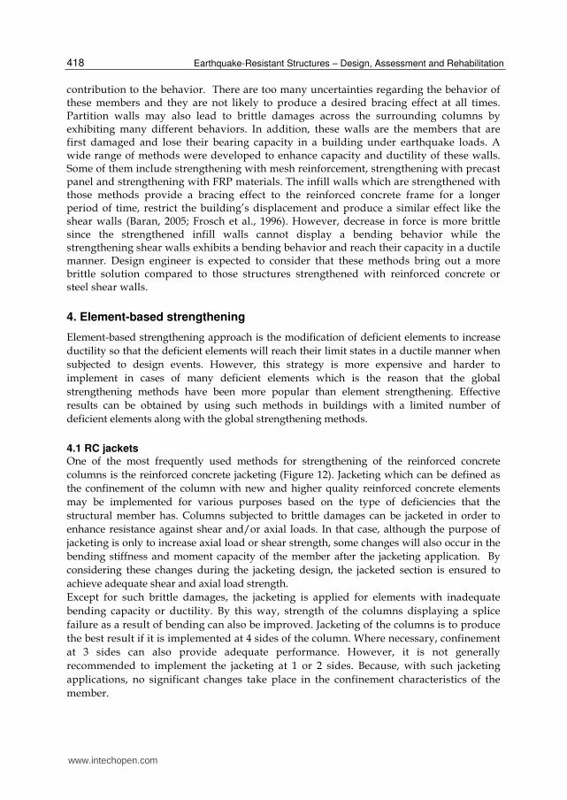
4.1 RC jackets One of the most frequently used methods for strengthening of the reinforced concrete columns is the reinforced concrete jacketing (Figure 12). Jacketing which can be defined as the confinement of the column with new and higher quality reinforced concrete elements may be implemented for various purposes based on the type of deficiencies that the structural member has. Columns subjected to brittle damages can be jacketed in order to enhance resistance against shear and/or axial loads. In that case, although the purpose of jacketing is only to increase axial load or shear strength, some changes will also occur in the bending stiffness and moment capacity of the member after the jacketing application. By considering these changes during the jacketing design, the jacketed section is ensured to achieve adequate shear and axial load strength. Except for such brittle damages, the jacketing is applied for elements with inadequate bending capacity or ductility. By this way, strength of the columns displaying a splice failure as a result of bending can also be improved. Jacketing of the columns is to produce the best result if it is implemented at 4 sides of the column. Where necessary, confinement at 3 sides can also provide adequate performance. However, it is not generally recommended to implement the jacketing at 1 or 2 sides. Because, with such jacketing applications, no significant changes take place in the confinement characteristics of the member.
www.intechopen.com
Seismic Strengthening of Reinforced Concrete Buildings
419
Fig. 12. An RC jacketing application (Photo by Ahmet Sarışın)
Although the reinforced concrete jacketing can technically be applied for all the structural members, a jacketing application which will increase the beam’s bending capacity is not advised since it may cause the strong beam-weak column formation resulted by an increase in the capacity of beam members.
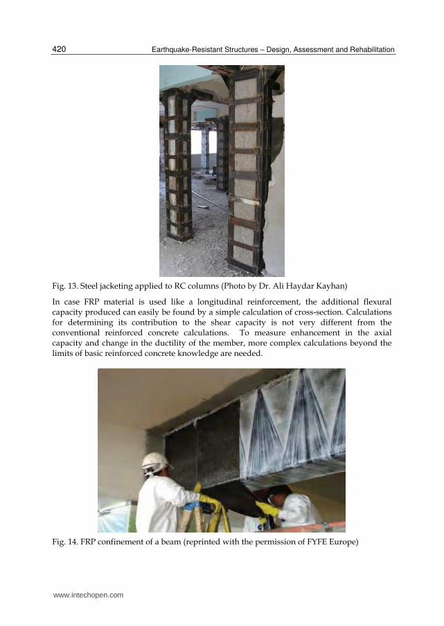
4.2 Steel jackets Jacketing with steel elements is a practical method used frequently for various applications. A typical steel jacketing application is presented in Figure 13. Steel jacketing can readily be used to especially enhance the shear strength of reinforced concrete elements. Located at the corners of an element, L-profiles are coupled by means of steel plates and confined. With the maintenance of continuity between storeys, steel jacketing can also be used to increase the bending strength. Also, the maintenance of adequate strength between the steel element and reinforced concrete element is inevitable for the improvement of bending capacity.
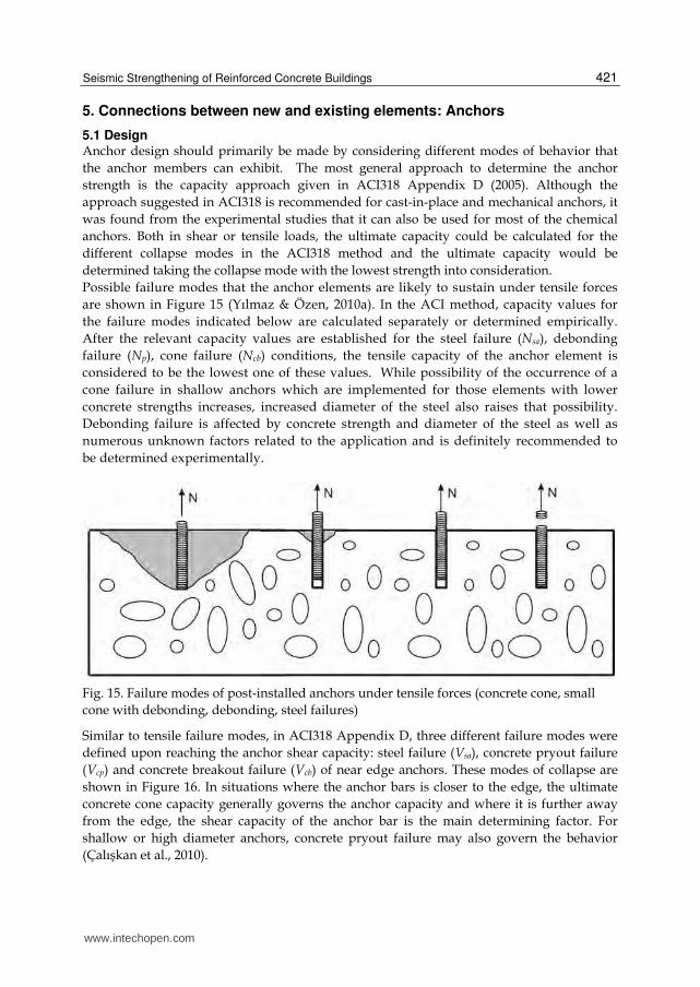
4.3 Fiber reinforced polymers In recent years, use of Fiber Reinforced Polymer has considerably become widespread in strengthening applications. Fiber polymer fabrics that can be used to improve bending, shear and axial capacities of the columns and beams may be manufactured from various materials such as carbon, glass and aramidWithout an increase in the volume of the strengthened member, significant improvements can be achieved in the capacity and ductility characteristics of the element. In Figure 14, beam strenghthening for a parking structure is shown. Due to space restrictions in this structure, it was not feasible to utilize classical element strengthening techniques. These materials may practically be used for numerous purposes such as enhancement of the flexural capacity of floor slabs and improvement of shear capacity of beams, columns or shear walls.
www.intechopen.com
Earthquake-Resistant Structures – Design, Assessment and Rehabilitation
420
Fig. 13. Steel jacketing applied to RC columns (Photo by Dr. Ali Haydar Kayhan)
In case FRP material is used like a longitudinal reinforcement, the additional flexural capacity produced can easily be found by a simple calculation of cross-section. Calculations for determining its contribution to the shear capacity is not very different from the conventional reinforced concrete calculations. To measure enhancement in the axial capacity and change in the ductility of the member, more complex calculations beyond the limits of basic reinforced concrete knowledge are needed.
Fig. 14. FRP confinement of a beam (reprinted with the permission of FYFE Europe)
www.intechopen.com
Seismic Strengthening of Reinforced Concrete Buildings
421
5. Connections between new and existing elements: Anchors
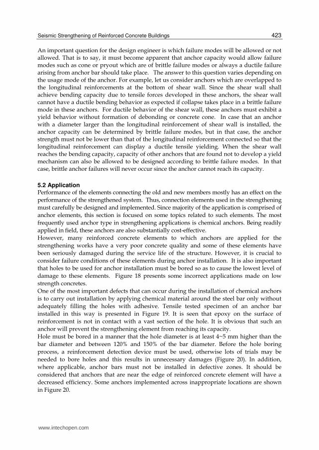
5.1 Design Anchor design should primarily be made by considering different modes of behavior that the anchor members can exhibit. The most general approach to determine the anchor strength is the capacity approach given in ACI318 Appendix D (2005). Although the approach suggested in ACI318 is recommended for cast-in-place and mechanical anchors, it was found from the experimental studies that it can also be used for most of the chemical anchors. Both in shear or tensile loads, the ultimate capacity could be calculated for the different collapse modes in the ACI318 method and the ultimate capacity would be determined taking the collapse mode with the lowest strength into consideration. Possible failure modes that the anchor elements are likely to sustain under tensile forces are shown in Figure 15 (Yılmaz & Özen, 2010a). In the ACI method, capacity values for the failure modes indicated below are calculated separately or determined empirically. After the relevant capacity values are established for the steel failure (Nsa), debonding failure (Np), cone failure (Ncb) conditions, the tensile capacity of the anchor element is considered to be the lowest one of these values. While possibility of the occurrence of a cone failure in shallow anchors which are implemented for those elements with lower concrete strengths increases, increased diameter of the steel also raises that possibility. Debonding failure is affected by concrete strength and diameter of the steel as well as numerous unknown factors related to the application and is definitely recommended to be determined experimentally.
Fig. 15. Failure modes of post-installed anchors under tensile forces (concrete cone, small cone with debonding, debonding, steel failures)
Similar to tensile failure modes, in ACI318 Appendix D, three different failure modes were defined upon reaching the anchor shear capacity: steel failure (Vsa), concrete pryout failure (Vcp) and concrete breakout failure (Vcb) of near edge anchors. These modes of collapse are shown in Figure 16. In situations where the anchor bars is closer to the edge, the ultimate concrete cone capacity generally governs the anchor capacity and where it is further away from the edge, the shear capacity of the anchor bar is the main determining factor. For shallow or high diameter anchors, concrete pryout failure may also govern the behavior (Çalışkan et al., 2010).
www.intechopen.com

Earthquake-Resistant Structures – Design, Assessment and Rehabilitation
422
Tensile or shear capacity determined with the abovementioned approach should be reduced by a strength reduction coefficient for design purposes. Various coefficients are listed in ACI318 depending on the environmental conditions and workmanship quality. These reduction coefficients vary between 0.45 and 0.75 depending on the loading type, failure mode and reliability of the application. Details of the formulations are to be studied from related codes or standards.
Fig. 16. Failure modes of post-installed anchors under shear forces
In some studies carried out recently on low strength concretes, it is suggested to use a reduction coefficient depending on the diameter of reinforcement when the anchor capacity is governed by steel failure mode per ACI318 formulations. Accordingly, the strength of reinforcements with larger diameters (bar diameters greater than 16mm) should be reduced, as seen in Figure 17. Research on this area is not completed yet. Designers are recommended to use high diameter bars with concern.
Fig. 17. Strength reduction for steel failure mode depending on bar diameter
www.intechopen.com
Seismic Strengthening of Reinforced Concrete Buildings
423
An important question for the design engineer is which failure modes will be allowed or not allowed. That is to say, it must become apparent that anchor capacity would allow failure modes such as cone or pryout which are of brittle failure modes or always a ductile failure arising from anchor bar should take place. The answer to this question varies depending on the usage mode of the anchor. For example, let us consider anchors which are overlapped to the longitudinal reinforcements at the bottom of shear wall. Since the shear wall shall achieve bending capacity due to tensile forces developed in these anchors, the shear wall cannot have a ductile bending behavior as expected if collapse takes place in a brittle failure mode in these anchors. For ductile behavior of the shear wall, these anchors must exhibit a yield behavior without formation of debonding or concrete cone. In case that an anchor with a diameter larger than the longitudinal reinforcement of shear wall is installed, the anchor capacity can be determined by brittle failure modes, but in that case, the anchor strength must not be lower than that of the longitudinal reinforcement connected so that the longitudinal reinforcement can display a ductile tensile yielding. When the shear wall reaches the bending capacity, capacity of other anchors that are found not to develop a yield mechanism can also be allowed to be designed according to brittle failure modes. In that case, brittle anchor failures will never occur since the anchor cannot reach its capacity.
5.2 Application Performance of the elements connecting the old and new members mostly has an effect on the performance of the strengthened system. Thus, connection elements used in the strengthening must carefully be designed and implemented. Since majority of the application is comprised of anchor elements, this section is focused on some topics related to such elements. The most frequently used anchor type in strengthening applications is chemical anchors. Being readily applied in field, these anchors are also substantially cost-effective. However, many reinforced concrete elements to which anchors are applied for the strengthening works have a very poor concrete quality and some of these elements have been seriously damaged during the service life of the structure. However, it is crucial to consider failure conditions of these elements during anchor installation. It is also important that holes to be used for anchor installation must be bored so as to cause the lowest level of damage to these elements. Figure 18 presents some incorrect applications made on low strength concretes. One of the most important defects that can occur during the installation of chemical anchors is to carry out installation by applying chemical material around the steel bar only without adequately filling the holes with adhesive. Tensile tested specimen of an anchor bar installed in this way is presented in Figure 19. It is seen that epoxy on the surface of reinforcement is not in contact with a vast section of the hole. It is obvious that such an anchor will prevent the strengthening element from reaching its capacity. Hole must be bored in a manner that the hole diameter is at least 4~5 mm higher than the bar diameter and between 120% and 150% of the bar diameter. Before the hole boring process, a reinforcement detection device must be used, otherwise lots of trials may be needed to bore holes and this results in unnecessary damages (Figure 20). In addition, where applicable, anchor bars must not be installed in defective zones. It should be considered that anchors that are near the edge of reinforced concrete element will have a decreased efficiency. Some anchors implemented across inappropriate locations are shown in Figure 20.
www.intechopen.com

Earthquake-Resistant Structures – Design, Assessment and Rehabilitation
424
Fig. 18. Poorly implemented anchor examples (A, B: anchors implemented on defective surfaces; C: Anchor implemented near a crack; D: Anchor fracturing the concrete during the tensile test)
Fig. 19. Interlocking surface in an anchor installed into a hole which is not filled with epoxy (Photo by Dr. Halil Nohutcu)
www.intechopen.com

Seismic Strengthening of Reinforced Concrete Buildings
425
Fig. 20. Inappropriate anchor layouts
www.intechopen.com

Earthquake-Resistant Structures – Design, Assessment and Rehabilitation
426
6. Conclusion
A brief summary of the available literature on seismic strengthening methods is presented in this chapter. In general, the structural engineer has alternatives of element based and system based methods. Element based techniques are more economical solutions when local problems are the main reason of the strengthening decision. If the problems related with the global ductility, stiffness or strength of the structure are the main concern, global strengthening techniques are more advantageous. Both approaches can also be utilized if needed. On the other hand, performance of the elements connecting the old and new members mostly has a vital effect on the performance of the strengthened system. Thus, connection elements used in the strengthening must carefully be designed and implemented. Since majority of the application is comprised of anchor elements, this section is focused on some topics related to anchors.
7. Acknowledgment
Authors greatly acknowledges Dr. Halil Nohutcu, Dr. Nihat Cetinkaya, Dr. Özlem Çalışkan, Ahmet Sarisin, and Prof. Dr. Ergin Atimtay for their efforts and contributions in experimental program on external shear walls. Dr. Yavuz Selim Tama, Dr. Ali Haydar Kayhan are also acknowledged for providing some photos on strengthening. Authors supervises several strengthening projects and carried out many research projects. Funding institutions (TUBITAK, DPT and Pamukkale University) and organizations (Denizli, Mugla and Kütahya Governorships) are also acknowledged for their valuable support.
8. References
ACI Committee 318. Building code requirements for structural concrete and commentary (ACI 318M-05). American Concrete Institute, 2005.
Albanesi T., Biondi S., Candigliota E. and Nuti C. Experimental analysis on a regular full scale infilled frame. Proceedings of the First European Conference on Earthquake Engineering and Seismology, Geneva, 2006, Paper No. 1608.
Baran M. Precast Concrete Panel Infill Walls for Seismic Strengthening of Reinforced Concrete Framed Strcutures. PhD thesis, Middle East Technical University, Ankara, 2005.
Bush T. D., Wyllie L. A. and Jirsa, J. O. Observations on two seismic strengthening schemes for concrete frames. Earthquake Spectra, 1991, 7, No.4, 511-527.
Çalışkan, Ö., Yilmaz, S., Kaplan, H., “Shear Capacity of Post-Installed Anchors According to ACI318 and TS500” 9th International Congress on Advances in Civil Engineering, 2010, Trabzon, Turkey.
Canbay E., Ersoy U. and Ozcebe G. Contribution of reinforced concrete infills to seismic behavior of structural systems. ACI Structural Journal, 2003, 100, No.5, 637-643.
Frosch R. J., Wanzhi L., Jirsa J. O. and Kreger M. E. Retrofit of non-ductile moment-resisting frames using precast infill wall panels. Earthquake Spectra, 1996, 12, No.4, 741-760.
www.intechopen.com
Seismic Strengthening of Reinforced Concrete Buildings
427
Gilmore A. T., Bertero V. V. and Youssef N. F. G. Seismic rehabilitation of infilled non-ductile frame buildings using post-tensioned steel braces. Earthquake Spectra, 1996, 12, No.4, 863-882.
Gorgulu, T., Tama, Y.S., Yilmaz, S., Kaplan, H., Ay, Z., Strengthening of Reinforced Concrete Structures With External Steel Shear Walls, Journal of Constructional Steel Research, 2011, doi:10.1016/j.jcsr.2011.08.010.
Higashi Y., Endo T. and Shimizu Y. Effects on behaviors of reinforced concrete frames by adding shear walls. Proceedings of the Third Seminar on Repair and Retrofit of Structures, Michigan, 1982, pp. 265-290.
Jirsa J. and Kreger M. Recent research on repair and strengthening of reinforced concrete structures. Proceedings of the ASCE Structures Congress, California, 1989, 1, 679-688.
Kaltakci, M.Y., Arslan, M. H., Yilmaz, U. S. and Arslan, H. D. A new approach on the strengthening of primary school buildings in Turkey: An application of external shear wall, Building and Environment, 2008, 43, No.6, 983-990.
Kaplan, H., Yılmaz, S., Cetinkaya, N., Atımtay, E., Seismic strengthening of RC structures with exterior shear walls, Sadhana - Academy Proceedings in Engineering Science, 2011, 36(1), 17-34.
Kaplan, H., Yılmaz, S., Cetinkaya, N., Nohutcu, H. and Atımtay, E. Gönen, H. A New Method for Strengthening of Precast Industrial Structures. Journal of The Faculty of Engineering and Architecture of Gazi University, 2009, 24 No.4, 659-665, (in Turkish).
Masri A. and Goel S. Seismic design and testing of an RC slab-column frame strengthened with steel bracing. Earthquake Spectra, 1996, 12, No.4, 645-666.
TEC-2007, Ministry of Public Works and Settlement, Turkish Earthquake Code-2007: Specifications for buildings to be built in seismic areas. Ankara, Turkey (in Turkish), 2007.
Moehle J. P. State of research on seismic retrofit of concrete building structures in the US. Proceeding of US-Japan Symposium and Workshop on Seismic Retrofit of Concrete Structures - State of Research and Practice, USA, 2000.
Ohmura, T., Hayashi, S., Kanata, K. and Fujimura, T., Seismic retrofit of reinforced concrete frames by steel braces using no anchors. Proceedings of the 8th National Conference on Earthquake Engineering. California, 2006.
Perera, R., Gómez, S. and Alarcón, E. Experimental and analytical study of masonry infill reinforced concrete frames retrofitted with steel braces. ASCE Journal of Structural Engineering, 2004, 130, No.12, 2032-2039.
Sonuvar M. O., Ozcebe G. and Ersoy, U. Rehabilitation of reinforced concrete frames with reinforced concrete infills. ACI Structural Journal, 2004, 101, No.4, 494-500.
Sucuoglu H., Jury R., Ozmen A., Hopkins D. and Ozcebe G. Developing retrofit solutions for the residential building stocks in Istanbul. Proceedings of 100th Anniversary Earthquake Conference, California, 2006
Whitney, C.S., Anderson, B.G. ve Cohen, E., Design of Blast Resistant Construction for Atomic Explosions, ACI Structural Journal, 1955, 26(7):589-683.
Yakut A., Gülkan P., Bakır B.S., Yılmaz M.T., Re-examination of damage distribution in Adapazarı structural considerations. Engineering Structures, 2005, 27, No.7, 990-1001.
www.intechopen.com

Earthquake-Resistant Structures – Design, Assessment and Rehabilitation
428
Yılmaz, S., Cetinkaya, N., Nohutcu, H., Caliskan, O., Çırak, İ.F., Experimental Investigation on Anchor Applications for External Shear Walls, Technical Report, 192 p, 2010a, Denizli.
Yılmaz, S., Kaplan, H., Çalışkan, Ö., Kıraç, N., “Cyclic Shear Resistance of Epoxy Anchors Bonded to Low Strength Concrete” 14th European Conference on Earthquake Engineering, Paper no. 510, 2010b, Ohrid, Macedonia.
Yılmaz, S., Özen M.A., “Tensile Strength of Chemical Anchors Embedded to Low and Normal Strength Concrete” Pamukkale University, Report no: 2009FBE025, 131 p. 2010a, Denizli (in Turkish).
Yılmaz, S., Özen, M.A., “Strength of Chemical Anchors Embedded to Low Strength Concrete” 14th European Conference on Earthquake Engineering, Paper no. 513, 2010b, Ohrid, Macedonia.
Yılmaz, S., Tama, Y.S., Kaplan, H., “Design and Construction of External Precast Shear Walls for Seismic Retrofit” 14th European Conference on Earthquake Engineering, Paper no. 1238, 2010c, Ohrid, Macedonia.
Yılmaz, S., Kaplan, H., Tama, Y.S., Çalışkan, Ö., Solak, A., “Experimental program on design and application of external retrofit walls for low ductility RC frames” 4th International Conference on Advances in Experimental Structural Engineering, 2011, Ispra, Italy.
www.intechopen.com
Earthquake-Resistant Structures - Design, Assessment andRehabilitationEdited by Prof. Abbas Moustafa
ISBN 978-953-51-0123-9Hard cover, 524 pagesPublisher InTechPublished online 29, February, 2012Published in print edition February, 2012
InTech EuropeUniversity Campus STeP Ri Slavka Krautzeka 83/A 51000 Rijeka, Croatia Phone: +385 (51) 770 447 Fax: +385 (51) 686 166www.intechopen.com
InTech ChinaUnit 405, Office Block, Hotel Equatorial Shanghai No.65, Yan An Road (West), Shanghai, 200040, China
Phone: +86-21-62489820 Fax: +86-21-62489821
This book deals with earthquake-resistant structures, such as, buildings, bridges and liquid storage tanks. Itcontains twenty chapters covering several interesting research topics written by researchers and experts in thefield of earthquake engineering. The book covers seismic-resistance design of masonry and reinforcedconcrete structures to be constructed as well as safety assessment, strengthening and rehabilitation of existingstructures against earthquake loads. It also includes three chapters on electromagnetic sensing techniques forhealth assessment of structures, post earthquake assessment of steel buildings in fire environment andresponse of underground pipes to blast loads. The book provides the state-of-the-art on recent progress inearthquake-resistant structures. It should be useful to graduate students, researchers and practicing structuralengineers.
How to referenceIn order to correctly reference this scholarly work, feel free to copy and paste the following:
Hasan Kaplan and Salih Yılmaz (2012). Seismic Strengthening of Reinforced Concrete Buildings, Earthquake-Resistant Structures - Design, Assessment and Rehabilitation, Prof. Abbas Moustafa (Ed.), ISBN: 978-953-51-0123-9, InTech, Available from: http://www.intechopen.com/books/earthquake-resistant-structures-design-assessment-and-rehabilitation/seismic-strengthening-of-reinforced-concrete-buildings

© 2012 The Author(s). Licensee IntechOpen. This is an open access articledistributed under the terms of the Creative Commons Attribution 3.0License, which permits unrestricted use, distribution, and reproduction inany medium, provided the original work is properly cited.