Seismic-Sequence Stratigraphy and Geologic Structure of ...Seismic-Sequence Stratigraphy and...
38
Seismic-Sequence Stratigraphy and Geologic Structure of the Floridan Aquifer System Near “Boulder Zone” Deep Wells in Miami-Dade County, Florida By Kevin J. Cunningham Prepared in cooperation with the Miami-Dade Water and Sewer Department Scientific Investigations Report 2015–5013 U.S. Department of the Interior U.S. Geological Survey L INT-009
Transcript of Seismic-Sequence Stratigraphy and Geologic Structure of ...Seismic-Sequence Stratigraphy and...

Seismic-Sequence Stratigraphy and Geologic Structure of the Floridan Aquifer System Near “Boulder Zone” Deep Wells in Miami-Dade County, Florida
By Kevin J. Cunningham
Prepared in cooperation with the Miami-Dade Water and Sewer Department
Scientific Investigations Report 2015–5013
U.S. Department of the InteriorU.S. Geological Survey
INT-009

U.S. Department of the InteriorSALLY JEWELL, Secretary
U.S. Geological SurveySuzette M. Kimball, Acting Director
U.S. Geological Survey, Reston, Virginia: 2015
For more information on the USGS—the Federal source for science about the Earth, its natural and living resources, natural hazards, and the environment—visit http://www.usgs.gov or call 1–888–ASK–USGS.
For an overview of USGS information products, including maps, imagery, and publications, visit http://www.usgs.gov/pubprod/.
Any use of trade, firm, or product names is for descriptive purposes only and does not imply endorsement by the U.S. Government.
Although this information product, for the most part, is in the public domain, it also may contain copyrighted materials as noted in the text. Permission to reproduce copyrighted items must be secured from the copyright owner.
Suggested citation:Cunningham, K.J., 2015, Seismic-sequence stratigraphy and geologic structure of the Floridan aquifer system near “Boulder Zone” deep wells in Miami-Dade County, Florida: U.S. Geological Survey Scientific Investigations Report 2015–5013, 28 p., http://dx.doi.org/10.3133/sir20155013.
ISSN 2328-0328 (online)

iii
Acknowledgments
Cameron Walker and William J. Streidl, Walker Marine Geophysical Company, provided expert seismic-reflection data acquisition. Virginia Walsh, Miami-Dade Water and Sewer Department, granted access to Miami-Dade North and South District “Boulder Zone” Well Fields. Jeff N. King, USGS, provided very useful technical discussions. Richard L. Westcott, USGS, contrib-uted to interpretation of borehole videos, assistance with geophysical well log display, and construction of a geomodel.


v
Contents
Abstract ...........................................................................................................................................................1Introduction.....................................................................................................................................................1
Purpose and Scope ..............................................................................................................................6Methods of Study ..................................................................................................................................6
Geologic Setting of the Floridan Aquifer System .....................................................................................7Hydrogeology.........................................................................................................................................7Avon Park Formation-Arcadia Formation Contact in the Area of the North and South
District “Boulder Zone” Well Fields ....................................................................................7Tectonic and Structural Setting of the Florida Platform .................................................................9
Seismic-Sequence Stratigraphy of the Floridan Aquifer System ........................................................10Seismic-Sequence Stratigraphy of the Arcadia Formation and Stock Island Formation .......10Seismic Sequence 1 ...........................................................................................................................11Seismic Sequence 2 ..........................................................................................................................11Seismic Sequence 3 ...........................................................................................................................15Seismic Sequence 4 ...........................................................................................................................16
Geologic Structure of the Floridan Aquifer System ...............................................................................16Tectonic Faults ....................................................................................................................................18Buried Karst Collapse.........................................................................................................................23
Summary and Conclusions .........................................................................................................................24References Cited..........................................................................................................................................24
Plates[ Available at http://pubs.usgs.gov/sir/2015/5013/] 1 Seismic-reflection sections A–A’, B–B’, and C–C’ with correlations between
synthetic seismograms, borehole geophysical data, and seismic-reflection profiles from the North and South District “Boulder Zone” Well Fields, Miami-Dade County, Florida
2 Hydrologic, lithostratigraphic, seismic sequence, and depositional sequence section through North District “Boulder Zone” Well Field, Miami-Dade County, Florida
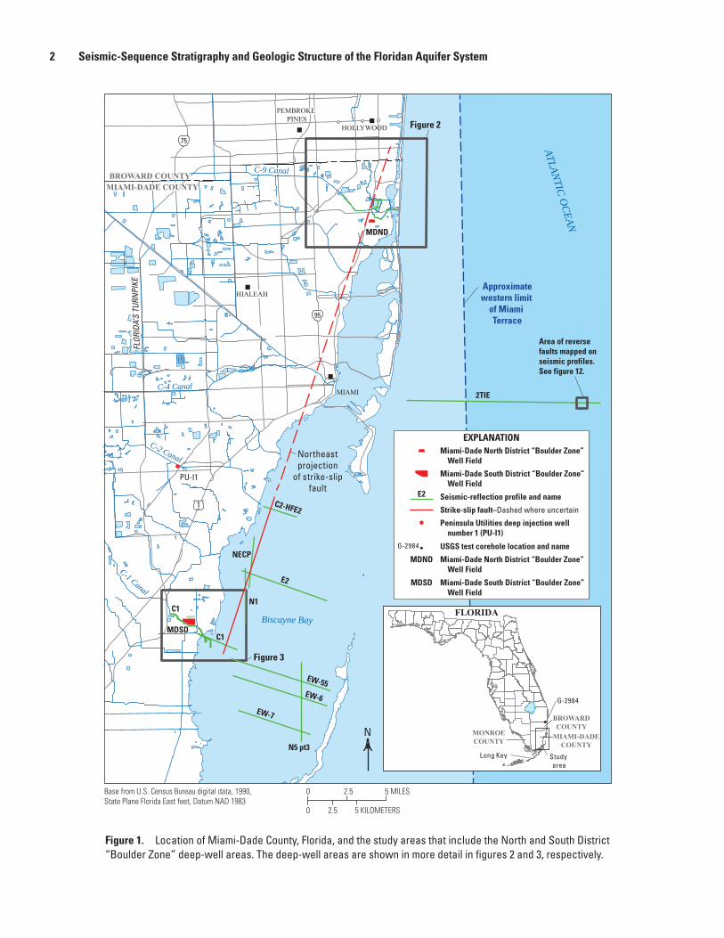
Figures 1. Map showing location of Miami-Dade County, Florida, and the study areas
that include the North and South District “Boulder Zone” deep-well areas .....................2 2. Map showing location of the North District “Boulder Zone” deep-well area,
where “Boulder Zone” deep wells MD-IW-1N through MD-IW-4N are located and the location of seismic-reflection survey profiles used in this study area .................3
3. Map showing the location of the South District “Boulder Zone” deep-well area, where “Boulder Zone” deep wells MD-IW-1S through MD-IW-17S and BZ-1 are located and the location of seismic-reflection survey profiles used in this study area .................................................................................................................4

vi
4. Correlation chart showing relations between hydrogeologic units, geologic units, and seismic-stratigraphic units .......................................................................................5
5. Map of conceptualized paleogeography about 140 Mya depicting a fully assembled Florida basement ......................................................................................................9
6. Seismic-reflection profile examples of seismic sequences 1–4, which combine to span the lower part of the intermediate confining unit and Floridan aquifer system excluding the part below the Boulder Zone ................................12
7. Seismic-reflection profile N5-pt3 from Biscayne Bay showing a broad sag in seismic reflections interpreted as a collapse structure within the middle Eocene carbonate strata of the Floridan aquifer system .....................................................13
8. Seismic-reflection profile EW7 acquired in Biscayne Bay showing downlapping seismic reflections along the top of seismic sequence 1 and onlapping seismic reflections along the tops of seismic sequence 2 and seismic sequence 3 ....................................................................................................................14
9. Part of seismic reflection profile 2TIE showing inverted V-shaped stacked seismic-reflection configurations within seismic sequence 2, indicative of a narrow karst collapse structure ...........................................................................................15
10. Three-dimensional diagram showing geomodel of the Miami-Dade North District “Boulder Zone” Well Field and surrounding area constructed from well-log data and seismic-reflection profiles ........................................................................17
11. Seismic-reflection profile N1 from Biscayne Bay showing a nearly vertical strike-slip fault .............................................................................................................................19
12. Seismic-reflection profile C2–HFE2 showing a near-vertical strike-slip fault and a narrow karst collapse structure west of the fault .............................................20
13. Three-dimensional diagram of geomodel based on 20 seismic-reflection profiles, including the 2TIE seismic-reflection profile ..........................................................21
14. Part of seismic-reflection profile 2TIE showing tectonic compressional anticlinal uplift, truncated seismic-reflection terminations at the upper bounding sequence boundary of the lower Arcadia formation, and downlapping reflections assigned to upper Pliocene or lower Pleistocene sediments .....................................................................................................................................22

vii
Conversion Factors
Multiply By To obtain
Length
foot (ft) 0.3048 meter (m)mile (mi) 1.609 kilometer (km)
Velocity
mile per hour (mi/h) 1.609 kilometer per hour (km/h)
DatumHorizontal coordinate information is referenced to the North American Datum of 1983 (NAD 83).
Altitude, as used in this report, refers to distance above or below sea level.
Supplemental InformationConcentrations of chemical constituents in water are given in milligrams per liter (mg/L)
Abbreviations
bls below land surfacems millisecondMDWASD Miami-Dade Water and Sewer DepartmentNDBZWF North District “Boulder Zone” Well Fields secondSDBZWF South District “Boulder Zone” Well FieldUSDW underground source of drinking waterUSGS U.S. Geological Survey


Seismic-Sequence Stratigraphy and Geologic Structure of the Floridan Aquifer System Near “Boulder Zone” Deep Wells in Miami-Dade County, Florida
By Kevin J. Cunningham
Abstract
The U.S. Geological Survey, in cooperation with the Miami-Dade Water and Sewer Department, acquired,
North and South District ”Boulder Zone” Well Fields to deter-mine if geologic factors may contribute to the upward migra-
aquifer system designated by the U.S. Environmental Protec-tion Agency as an underground source of drinking water. The depth of the Boulder Zone at the North and South District ”Boulder Zone” Well Fields ranges from about 2,750 to 3,300 feet below land surface (ft bls), whereas overlying permeable zones used as alternative drinking water supply range in depth from about 825 to 1,580 ft bls at the North and South District “Boulder Zone” Well Fields. Seismic-sequence stratigraphy and geologic structures imaged on seismic-
the Floridan aquifer system overlying and within the Boulder Zone. Features of the Floridan aquifer system underlying the
Zone” Well Fields lacked adequate resolution at such depths.
from the study area was mainly applied to the Floridan aquifer system and used to identify four provisional seismic sequences, which extend vertically from near the base of the Floridan aquifer system upward to the lower part of the
compose a framework in which each sequence includes a major permeable unit of the Floridan aquifer system; from shallowest to deepest, these units are the Upper Floridan aquifer, Avon Park permeable zone, uppermost major perme-able zone of the Lower Floridan aquifer, and Boulder Zone. The relations between seismic-sequence stratigraphy and hydrostratigraphy allow for detailed mapping of permeable
at a level of resolution never before accomplished using well data alone.
injection wells at the North District ”Boulder Zone” Well Field delineated a narrow karst collapse structure beneath the injection facility that extends upward about 900 ft from the top of the Boulder Zone to about 125 ft above the top of the uppermost major permeable zone of the Lower Floridan
”Boulder Zone” Well Field. However, karst collapse structures at the level of the lowermost major permeable zone of the Lower Floridan aquifer at the South District ”Boulder Zone” Well Field are present at three locations, as indicated by
the south side of the injection facility. Results from the North District ”Boulder Zone” Well Field well data indicate that a plausible hydraulic connection between faults and stratiform permeability zones may contribute to the upward transport
Environmental Protection Agency designated underground source of drinking water at the North District ”Boulder Zone” Well Field.
IntroductionThe Miami-Dade Water and Sewer Department
into the saline Boulder Zone, a highly transmissive hydro-geologic unit within the Oldsmar Formation and the lower
wells at both the North District ”Boulder Zone” Well Field (NDBZWF) and South District ”Boulder Zone” Well Field (SDBZWF) ( ). The depth of the Boulder Zone at the NDBZWF and SDBZWF ranges from about 2,750 to 3,300 feet below land surface (ft bls), whereas overlying permeable zones used as alternative drinking water supply range in depth from about 825 to 1,580 ft bls at NDBZWF
the Boulder Zone beneath the deepest underground source
2 Seismic-Sequence Stratigraphy and Geologic Structure of the Floridan Aquifer System
N
MDSD
MDND
EXPLANATION
Peninsula Utilities deep injection well number 1 (PU-I1)
Strike-slip fault–Dashed where uncertain
USGS test corehole location and name
Seismic-reflection profile and nameE2
G-2984
Miami-Dade North District “Boulder Zone” Well Field
Miami-Dade South District “Boulder Zone” Well Field
MDND Miami-Dade North District “Boulder Zone” Well Field
MDSD Miami-Dade South District “Boulder Zone” Well Field
BROWARD COUNTYMIAMI-DADE COUNTY
PU-I1
Figure 3
Figure 2
EW-55EW-6
EW-7
95
FLOR
IDA’
S TU
RNPI
KE
ATLANTIC OCEAN
2TIE
Approximatewestern limit
of Miami Terrace
Area of reversefaults mapped on seismic profiles.See figure 12.
N5 pt3
N1
C2-HFE2
E2
NECP
C1
C1
Northeastprojection
of strike-slipfault
0 2.5 5 MILES
0 2.5 5 KILOMETERS
75
95
HOLLYWOOD
PEMBROKEPINES
HIALEAH
MIAMI
Biscayne Bay
C-1 Canal
C-2 Canal
C-4 Canal
C-9 Canal
1
Base from U.S. Census Bureau digital data, 1990,State Plane Florida East feet, Datum NAD 1983
FLORIDA
Study area
G-2984
Long Key
MONROECOUNTY
MIAMI-DADECOUNTY
BROWARDCOUNTY
Figure 1. Location of Miami-Dade County, Florida, and the study areas that include the North and South District “Boulder Zone” deep-well areas. The deep-well areas are shown in more detail in figures 2 and 3, respectively.

Introduction 3
G–3949
G–3948 MD–IW–2
MD–IW–1
Biscayne Landing
MD–IW–4MD–IW–3
MD–IW–1
1
441
BROWARD COUNTYMIAMI-DADE COUNTY
NDBCP2
NDBC NDCD
NDkl
NDfg
NDh
j
NDde
NDQR
MDND
NDABC
NDDETWO
0 0.5 1 MILE
0 0.5 1 KILOMETER
95 A1A
C-8 Canal
C-9 Canal
Oleta
MauleLake
ATLA
NTIC
OCE
AN
Intra
coas
tal W
ater
way
River
Base from U.S. Census Bureau digital data, 1990,State Plane Florida East feet, Datum NAD 1983
N
Unce
rtai
n st
rike-
slip
faul
t
EXPLANATIONSeismic-reflection synthetic construction from geophysical logs
Miami-Dade North District “Boulder Zone” Well Field
MDND
MD–IW–4 Lower Floridan aquifer “Boulder Zone” deep well location and name
Seismic-reflection profile and name
G–3948 Surficial aquifer test well location and name
NDBC
Limit of seismic-reflection profile
Figure 2. North District “Boulder Zone” deep-well area, where “Boulder Zone” deep wells MD-IW-1N through MD-IW-4N are located and the location of seismic-reflection survey profiles used in this study area.

4 Seismic-Sequence Stratigraphy and Geologic Structure of the Floridan Aquifer System
MD–IW–10
MD–IW–8
MD–IW–7
MD–IW–6MD–IW–5
MD–IW–4
MD–IW–3MD–IW–2
MD–IW–1
MD–IW–17
MD–IW–16
MD–IW–15
MD–IW–14MD–IW–13
MD–IW–12
MD–IW–11
MD–IW–9
MDSDBZ1
EXPLANATION
Seismic-reflection profile and nameAB
CHI–1 Upper Floridan aquifer well location and name
MD–IW–9
Miami-Dade South District “Boulder Zone” Well Field
Lower Floridan aquifer “Boulder Zone” deep well location and name
MDSD
Seismic-reflection synthetic construction from geophysical logs
0 0.5 1 MILE
0 0.5 1 KILOMETER
Bisc
ayne
Bay
C-1 Canal
Leve
e 31
E
FLOR
IDA’
S TU
RNPI
KE
CHI–1
AB
BCS1
BCS2
DE2
C1
C1
SP–6 SP–4 SP–2SP–5 SP–3
C1
N
C1
Base from U.S. Census Bureau digital data, 1990,State Plane Florida East feet, Datum NAD 1983
Strik
e-sl
ip fa
ult
Figure 3. South District “Boulder Zone” deep-well area, where “Boulder Zone” deep wells MD-IW-1S through MD-IW-17S and BZ-1 are located and the location of seismic-reflection survey profiles used in this study area.

Introduction 5
transport from the Boulder Zone to overlying permeable
transport from injection zones to USDWs in the Floridan aquifer system.
In August 2008, the Florida Department of Environ-mental Protection required that MDWASD conduct a study
The present study was initiated in 2009 by the U.S. Geological Survey (USGS), in cooperation with MDWASD, to support
the overall investigation by providing geologic information about the stratigraphic and structural features that have
SDBZWF. This study provides hydrogeologic conceptualiza-tions (based on interpretations from recently acquired seismic-
areas of southeastern Florida.
Figure 4. Correlation chart showing relations between hydrogeologic units, geologic units, and seismic-stratigraphic units (based on information from Reese and Richardson [2008], Roberts-Ashby and others [2013], and data presented herein). Seismic-sequence boundaries shown on plates 1 and 2.
EXPLANATION
SSB Seismic-stratigraphic unit boundary
Avon Park permeable zone
Lower Arcadia Formation
BZ
APPZ
LF1
SS1
SL
OL
Suwannee Limestone–not present at MDND and presence uncertain at MDSD
Ocala Limestone–not present at MDND and presence uncertain at MDSD
MDND Miami-Dade North District “Boulder Zone” Well Field
MDSD
Geologic unit boundary–dashed where poorly defined or uncertain presence
Seismic-stratigraphic unit boundary–dashed where poorly defined
Uppermost major permeable zone of the Lower Floridan aquifer
Boulder Zone
Miami-Dade South District “Boulder Zone” Well Field
LAF
Seismic sequence and number
Hydrogeologic unit Geologic unit
Surfi
cial
aqui
fer s
yste
m
Confining beds
Confining unit
Inte
rmed
iate
con
finin
g un
it
Avon Park Formation
Oldsmar Formation
Sub-Floridan confining unit
Flor
idan
aqu
ifer s
yste
m
Peace RiverFormation
Cedar Keys Formation
Middle semiconfining unit 2
BZ
LF1
Middle semiconfining
unit 1
Biscayne aquifer
Gray limestoneaquifer
Upper Floridan aquifer
LowerFloridanaquifer
APPZ
(Includes permeable zonesand confining units)
Seismic-stratigraphic
unit
SSB
SSB
SSB
SSB
SSB
SSB
SSB
SSB
SSB
SS1
SS2
SS3
SS4SSB
Pleistocene formations
Tamiami Formation
Arcadia Formation
LAF
Upper Cretaceous Formations
StockIsland
FormationSSB
Lower Cretaceous Formations
(Permeable zonesand confining units)
Sub-
Flor
idan
uni
ts
Holocene sediments
Haw
thor
n Gr
oup
Uppe
r Arc
adia
Form
atio
n
SSB
not defined
SL OL
SSB
SSB
SSB

6 Seismic-Sequence Stratigraphy and Geologic Structure of the Floridan Aquifer System
Purpose and Scope
The main purpose of this report is to characterize the seismic-sequence stratigraphy and geologic structure of the Floridan aquifer system at the NDBZWF and SDBZWF in Miami-Dade County, Florida. Seismic-sequence stratigraphic and structural interpretations are presented for both water-
-
geophysical and geological borehole data from the NDBZWF
current understanding of the relation between seismic-sequence stratigraphy, imaged tectonic and karst structures,
from the Boulder Zone upward into USDWs in southeastern Florida. The seismic-sequence stratigraphy and geologic structures presented herein represent the part of the Floridan
parts of the Floridan aquifer system underlying the Boulder Zone were not studied because of an absence of resolution in
seismic energy, high-frequency seismic signal, and signal-to-noise ratio with increasing depth and within the Boulder Zone where highly irregular shapes and sizes of karst-produced megaporosity are present. The seismic-sequence framework and conceptualization of tectonic and karst seismic structures
planned or in progress.The foundations of seismic-sequence stratigraphy are the
-
about the structural setting of the rocks of the Floridan aquifer
depositional sequence boundaries, and hydrologic boundaries
Methods of Study
To examine the seismic-sequence stratigraphy and geologic structures of the rocks of the Floridan aquifer system in the study area that includes NDBZWF and SDBZWF,
-
positioning system acquired real-time positions. A land-based,
true amplitude and post-stack migration. Final interpretation
geomodeling software.
and geophysical log data acquired from wells. Borehole
synthetic seismogram used for correlation between well data
was used for correlation between well data collected at the
its synthetic seismogram was used to relate geologic and

Geologic Setting of the Floridan Aquifer System 7
of comparisons to published geologic and hydrogeologic
altitude than the corresponding high-amplitude positive
B–B
Geologic Setting of the Floridan Aquifer System
-
better delineate the lithostratigraphic units that compose much
Hydrogeology
-
and assigned a hydrostratigraphic nomenclature to permeable
and assigned a hydrostratigraphic nomenclature to permeable
where correlation to well data indicated that it is possible to map the four permeable zones at a regional scale using
Avon Park Formation-Arcadia Formation Contact in the Area of the North and South District “Boulder Zone” Well Fields
Observations made as part of this study provide no
gamma-ray log intervals in the formation reported to be

8 Seismic-Sequence Stratigraphy and Geologic Structure of the Floridan Aquifer System
Halimeda
-
Halimeda
-
-
-
-
-

Geologic Setting of the Floridan Aquifer System 9
Tectonic and Structural Setting of the Florida Platform
BahamasFractureZone
Paleoequator
PlateMovement
BahamasFractureZone
Paleoequator
Paleoequator
PlateMovement
Figure 5. Conceptualized paleogeography about 140 Mya depicting a fully assembled Florida basement. Seafloor spreading has since ended in the Gulf of Mexico and movement of the Yucatan and Florida-Bahama blocks has ceased. Modified from Ross and Scotesse (1988); reprinted and modified with written permission from Elsevier Limited, Oxford, United Kingdom. Bahamas fracture zone from Klitgord and others (1984) and Horton and others (1991).

10 Seismic-Sequence Stratigraphy and Geologic Structure of the Floridan Aquifer System
(Poag, 1991). During much of the time from the late Oligocene to Pliocene, terrigenous clastic deposition extended from northern Florida to the southern area of the platform (Enos and Perkins, 1977; Warzeski and others, 1996; Cunningham and others, 2003). Carbonate sedimentary deposits dominated the Florida Keys region during the Pleistocene.
Sproul and others (1972), Miller (1986), Duncan and others (1994), Reese (1994), Mitchell-Tapping and others (1999), and Cunningham and others (2012) documented faulting in the Eocene carbonate rocks of the Florida Platform that compose a major part of the of Floridan aquifer system. The authors did not explain the forcing mechanisms that created the faults, with the exception of Cunningham and
being related to tectonic movement. Tectonic faults observed in southeastern Florida (Cunningham and others, 2012) may be due to movement throughout the Bahamas fracture zone, which Klitgord and others (1984) reported as connecting the spreading center in the central Atlantic Ocean with a
alternative forcing mechanism for tectonic faulting in southern Florida, Missimer and Maliva (2004) offered evidence for late Miocene to Pliocene tectonic compression in the Tertiary sedimentary section of the southern part of the Florida Plat-form, which the authors suggested was related to peripheral responses to tectonic events in the Caribbean Basin. The origin of tectonic faults in southeastern Florida is discussed further in the Tectonic Faults section of this report.
Similar to many ancient carbonate platforms around the
enhanced porosity and permeability. Numerous karst collapse structures in the carbonate rocks of the southeastern part of the Florida Platform have been delineated in the rocks of the Flor-
interpreted by Cunningham and Walker (2009), Cunningham and others (2012), Cunningham (2013), and Reese and Cunningham (2013, 2014). Examples of similar karst collapse
Platform include those in the following areas: (1) northeast Florida (Kindinger and others, 2000; Spechler, 2001), (2) La Belle area of the Caloosahatchee River (Cunningham and others, 2001b), (3) Tampa Bay and Charlotte Harbor in west-central Florida (Missimer and Gardner, 1976; Evans and Hine, 1991; Hine and others, 2009), (4) northeast Florida
sinkhole district (Evans and others, 1994).
Seismic-Sequence Stratigraphy of the Floridan Aquifer System
A major result of the seismic-sequence stratigraphy
sequences (seismic sequences 1–4) that extend vertically from
the upper part of the Floridan aquifer system to near the base
framework established by Reese and Richardson (2008) for central and southern Florida, and Reese and Cunningham (2013, 2014) for eastern Broward County was linked to the
The tops of the seismic sequences correspond to both a lithostratigraphic formation and major cyclostratigraphic top or to the general location of a hydrogeologic unit top. The top of seismic sequence 1 corresponds with the top of the Avon Park Formation, the top of seismic sequence 2 with the approximate location of the top of the Avon Park permeable zone, the top of seismic sequence 3 with the approximate position of the top of the uppermost major permeable zone of the Lower Floridan aquifer, and the top of seismic sequence 4 with the approxi-
of the lower Arcadia Formation is also a prominent seismic-sequence boundary and depositional sequence boundary (pl. 1)
for the top of the Floridan aquifer system to occur within the
and Richardson, 2008; Reese and Cunningham, 2014). This preliminary seismic-sequence nomenclature may be revised as the scope of USGS investigation in southeastern Florida broadens in future studies.
Seismic-Sequence Stratigraphy of the Arcadia Formation and Stock Island Formation
The seismic-sequence stratigraphy of the Arcadia
delineation of the uppermost part of the Floridan aquifer
part of the NDBZWF study area imaged low-angle, east
into deeper water) assigned to the informal upper Arcadia Formation (cross-section A–
apparent dip) onto the upper surface of the lower Arcadia Formation (cross-section A–
A– , pl. 1). The
the Tamiami Formation and top of the lower Arcadia Forma-
(Miami-Dade

Seismic-Sequence Stratigraphy of the Floridan Aquifer System 11
-
-
A–
A–
-
-
Seismic Sequence 1
A–B
A–B
-
B
-
A–B
Seismic Sequence 2
C–D
C–D
D
DD
-

12 Seismic-Sequence Stratigraphy and Geologic Structure of the Floridan Aquifer System
Figu
re 6
. Se
ism
ic-r
efle
ctio
n pr
ofile
exa
mpl
es o
f sei
smic
seq
uenc
es 1
–4, w
hich
com
bine
to s
pan
the
low
er p
art o
f the
inte
rmed
iate
con
finin
g un
it an
d Fl
orid
an a
quife
r sy
stem
exc
ludi
ng th
e pa
rt be
low
the
Boul
der Z
one.
(A),
horiz
onta
l, pa
ralle
l sei
smic
-ref
lect
ion
geom
etrie
s ty
pica
l of s
eism
ic s
eque
nce
1 on
a s
eism
ic-r
efle
ctio
n pr
ofile
ac
quire
d on
the
C1 C
anal
nea
r the
Sou
th D
istri
ct “
Boul
der Z
one”
Wel
l Fie
ld (S
DBZW
F) (f
ig. 3
, sec
tion
B–B’
on
pl. 1
); (B
), ho
rizon
tal,
para
llel s
eism
ic-r
efle
ctio
n ge
omet
ries
typi
cal o
f sei
smic
seq
uenc
e 1
on s
eism
ic-r
efle
ctio
n pr
ofile
2TI
E ac
quire
d ov
er th
e M
iam
i Ter
race
(fig
. 1);
(C),
horiz
onta
l, pa
ralle
l sei
smic
-ref
lect
ion
geom
etrie
s ty
pica
l of
sei
smic
seq
uenc
e 2
on a
sei
smic
-ref
lect
ion
prof
ile a
cqui
red
on th
e C1
Can
al n
ear
the
SDBZ
WF
(fig.
3);
(D) h
orizo
ntal
, par
alle
l sei
smic
-ref
lect
ion
geom
etrie
s ty
pica
l of
sei
smic
seq
uenc
e 2
on s
eism
ic-r
efle
ctio
n pr
ofile
2TI
E (fi
g. 1
), in
clud
ing
two
thic
k, lo
wer
-ord
er s
eism
ic s
eque
nces
(arr
ows)
that
com
pose
sei
smic
seq
uenc
e 2;
(E
) hor
izont
al, p
aral
lel a
nd m
inor
cha
otic
sei
smic
-ref
lect
ion
geom
etrie
s ty
pica
l of s
eism
ic s
eque
nce
3 on
a s
eism
ic-r
efle
ctio
n pr
ofile
acq
uire
d on
the
C1 C
anal
nea
r the
SD
BZW
F (fi
g. 3
); (F
), pa
ralle
l sei
smic
-ref
lect
ion
geom
etrie
s ty
pica
l of s
eism
ic s
eque
nce
3 on
sei
smic
-ref
lect
ion
prof
ile 2
TIE
(fig.
1) a
nd in
clud
ing
a ka
rst c
olla
pse
stru
ctur
e;
(G),
mos
tly c
haot
ic a
nd m
inor
par
alle
l sei
smic
-ref
lect
ion
geom
etrie
s ty
pica
l of s
eism
ic s
eque
nce
4 in
the
land
-bas
ed s
eism
ic-r
efle
ctio
n pr
ofile
s (S
P2–6
) at t
he S
DBZW
F (c
ross
-sec
tion
C–C'
pl.
1); (
H) p
aral
lel a
nd m
inor
refle
ctio
n-fre
e se
ism
ic-r
efle
ctio
n ge
omet
ries
typi
cal o
f sei
smic
seq
uenc
e 4
in th
e se
ism
ic-r
efle
ctio
n pr
ofile
s ne
ar th
e N
orth
Dis
trict
“Bo
ulde
r Zon
e” W
ell F
ield
(fig
. 2) a
nd th
e on
lap
of re
flect
ions
at t
he b
ase
of s
eism
ic s
eque
nce
3 on
to th
e up
per b
ound
ary
of s
eism
ic s
eque
nce
4; a
nd
(I) p
aral
lel a
nd m
inor
cha
otic
sei
smic
-ref
lect
ion
geom
etrie
s ty
pica
l of s
eism
ic s
eque
nce
4 on
sei
smic
-ref
lect
ion
prof
ile 2
TIE
(fig.
1).
Two-way traveltime, in milliseconds2,
530
feet
500
600
2,53
0 fe
et
300
400
AB
2,34
6 fe
et
600
700
2,58
0 fe
et
400
500
600
DC
I
700
2,53
0 fe
et2,
271 f
eet
600
700
600
EF
2,00
0 fe
et8,
000
feet
266
feet
700
700
800
800
800
900
900
900
HG
SS1
SS1
SS2
SS2
SS3
SS3
SS4
SS4
SS4
EXPL
AN
ATIO
N SS2
Seis
mic
-seq
uenc
e bo
unda
ry–D
ashe
d
whe
re u
ncer
tain
Bur
ied
seis
mic
-ref
lect
ion
colla
pse
stru
ctur
e
Upw
ard
incr
ease
of s
eism
ic-r
efle
ctio
n
am
plitu
de
Onl
appi
ng s
eism
ic re
flect
ions
Seis
mic
seq
uenc
e an
d nu
mbe
r

Seismic-Sequence Stratigraphy of the Floridan Aquifer System 13
Figure 7. Seismic-reflection profile N5-pt3 from Biscayne Bay (fig. 1) showing a broad sag in seismic reflections interpreted as a collapse structure within the middle Eocene carbonate strata of the Floridan aquifer system. Onshore hydrostratigraphy is projected onto the profile. Modified from Cunningham and Walker (2009).
Suprastrataldeformation
Minorcollapsedpaleocave
system
Maincollapsedpaleocave
system
Top ofArcadia
Formation
Top of Tamiami
Formation
Top of Peace RiverFormation
~Top ofAvonPark
Formation
Inte
rmed
iate
con
finin
g un
itSA
Flor
idan
aqu
ifer s
yste
m
UFA
APPZ
LF1
APPZLF
1M
C1
Seis
mic
seq
uenc
e 1
Seis
mic
seq
uenc
e 2
Seis
mic
seq
uenc
e 3
Mid
dle
sem
icon
finin
g un
it 2
CU
NORTHShot point 954Latitude 25˚30´53.18˝ Longitude 080˚13´40.44˝
Shot point 4Latitude 25˚30´53.10˝Longitude 080˚13´40.44˝
SOUTH
0 0
100
200
300
400
800
1,000
1,200
1,400
1,600
1,800
2,000
2,400
2,200
2,600
2,800
3,000
600
500
600
700
Two-
way
trav
eltim
e, in
mill
isec
onds
Altit
ude,
in fe
et b
elow
sea
leve
l
200
400
800
0 0.5 1 MILES
0 0.5 1 KILOMETERS
Biscayne baySeafloor
UFA
EXPLANATION
Surficial aquifer system
Fault, dashed when uncertain
Collapsed paleocave system
Permeable zone
North and south limit of collapse structure
MC1
Confining unit
Permeable zone
SA
CU
PZ
Avon Park permeable zone
Middle semiconfining unit 1
LF1
APPZ
Uppermost major permeable zone of the Lower Floridan aquifer
UFA Upper Floridan aquifer
Seismic sequence boundaryTop of Tamiami Formation, dashed where uncertain
Top of Peace River Formation, dashed where uncertain

14 Seismic-Sequence Stratigraphy and Geologic Structure of the Floridan Aquifer System
300
250
350
450
550
650
400
800
1,00
0
1,20
0
1,40
0
1,60
0
1,80
0
2,00
0
2,40
0
2,20
0
2,60
0
2,80
0
3,00
0
500
600
700
Two-way traveltime, in milliseconds
Altitude, in feet below sea level
Seismic sequence 3Seismic sequence 2Seismic sequence 1
WES
TEA
ST
5.2
MIL
ES
Shot
poi
nt 1
063
Latit
ude
25˚2
8´06
.22˝
Lo
ngitu
de 0
80˚1
7´55
.92˝
Shot
poi
nt 1
Latit
ude
25˚2
6´42
.73˝
Long
itude
080
˚13´
06.0
8˝
0 0
500
500
1,00
0 FE
ET
1,00
0 M
ETER
S
EXPL
AN
ATIO
N
Dow
nlap
ping
sei
smic
refle
ctio
ns
Onl
appi
ng s
eism
ic re
flect
ions
Seis
mic
seq
uenc
e bo
unda
ry
LAF
Low
er A
rcad
ia F
orm
atio
n
UA
FU
pper
Arc
adia
For
mat
ionLAFUAF
Figu
re 8
. Se
ism
ic-r
efle
ctio
n pr
ofile
EW
7 ac
quire
d in
Bis
cayn
e Ba
y (fi
g. 1
) sho
win
g do
wnl
appi
ng s
eism
ic re
flect
ions
(dis
play
ed a
s th
e at
tribu
te m
easu
rem
ent o
f in
stan
tane
ous
phas
e) a
long
the
top
of s
eism
ic s
eque
nce
1 an
d on
lapp
ing
seis
mic
re
flect
ions
alo
ng th
e to
ps o
f sei
smic
seq
uenc
e 2
and
seis
mic
seq
uenc
e 3.

Seismic-Sequence Stratigraphy of the Floridan Aquifer System 15
Seismic Sequence 3
E–F
E;cross-section B–B
C–C
Figure 9. Part of seismic reflection profile 2TIE showing inverted V-shaped stacked seismic-reflection configurations within seismic sequence 2, indicative of a narrow karst collapse structure. The feature is centered at about shot point 1315 on line 2TIE (fig. 1).
1,800
1,600
2,000
2,200
600
590
580
570
560
550
660
670
680
690
650
640
630
620
610
700
720
Two-
way
trav
eltim
e, in
mill
isec
onds
WEST EAST
Seis
mic
seq
uenc
e 2
SS3
SS1
Altit
ude,
in fe
et b
elow
sea
leve
l
2,400
710
Shot point 1406Latitude 25˚42´40.84˝ Longitude 080˚01´48.97˝
Shot point 1266Latitude 25˚42´35.16˝Longitude 080˚01´09.23˝
EXPLANATIONSeismic sequence boundary
Collapse structure boundaries
SS1 Seismic sequence and number
0
0
500
500
1,000 FEET
1,000 METERS

16 Seismic-Sequence Stratigraphy and Geologic Structure of the Floridan Aquifer System
E
E–F
F
-
-
F
B–B
-
B–B
Seismic Sequence 4
G–H;cross-sections A–A C–C
I
H
I
H
I
Geologic Structure of the Floridan Aquifer System
-
B–B
-

Geologic Structure of the Floridan Aquifer System 17
Figure 10. Three-dimensional diagram showing geomodel of the Miami-Dade North District “Boulder Zone” Well Field and surrounding area constructed from well-log data and seismic-reflection profiles (fig. 2). Two white leader lines point to the karst collapse structure penetrated by the MD-IW–2N well (pl. 2) and mapped as a circular-shaped depression at the top of seismic sequences 3–4. Test wells G-3949 and G-3948 provided information on the stratigraphic units composing the surficial aquifer (figs. 2).
EXPLANATIONRelative depth along geomodel surface
Underground source of drinking water
North District Wastewater Treatment Plant
Shallow
Deep
0 1 MILE0.5
0 1 KILOMETER0.5USDW
NDWWTP
200
400
600
800
Two-
way
trav
eltim
e, in
mill
isec
onds
IW–4
IW–3
IW–2
IW–1G–3948
G–3949
Base of Biscayne aquifer andtop of intermediate
confining unit
Top of Floridan aquifersystem
USDW
Seismic sequence 3
Seismic sequence 4
Seismic sequence 2
NDWWTP
Plane of potential
fault
Karst collapsestructure at MD–IW–2
N
18 Seismic-Sequence Stratigraphy and Geologic Structure of the Floridan Aquifer System
Tectonic Faults
-
-
A–A
A A

Geologic Structure of the Floridan Aquifer System 19
Figure 11. Seismic-reflection profile N1 from Biscayne Bay (fig. 1) showing a nearly vertical strike-slip fault. The structure is visible on five different seismic-reflection profiles (C2–HFE2, NECP, E2, N1, and C1; fig. 1) indicating its trace is about 10 miles or more in length. Onshore hydrostratigraphy is projected onto profile, although the upper and lower boundaries of the permeable units are located approximately. Onshore, the Upper Floridan aquifer and Avon Park permeable zone are protected underground sources of drinking water. Modified from Cunningham and others (2012).
Inte
rmed
iate
con
finin
g un
itSA
Flor
idan
aqu
ifer s
yste
m
UFA
APPZ
LF1
Mid
dle
sem
icon
finin
gun
it 1
Seis
mic
seq
uenc
e 1
Seis
mic
seq
uenc
e 2
Seis
mic
seq
uenc
e 3
Conf
inin
g un
itM
iddl
e se
mic
onfin
ing
unit
2
0 0
100
200
300
400
800
1,000
1,200
1,400
1,600
1,800
2,000
2,400
2,200
2,600
2,800
3,000
600
500
600
700
Two-
way
trav
eltim
e, in
mill
isec
onds
Altit
ude,
in fe
et b
elow
sea
leve
l
200
400
800
3,200
3,400
Shot point 736Latitude 25˚36´15.83˝ Longitude 080˚17´15.29˝
Shot point 255Latitude 25˚34´10.89˝Longitude 080˚17´15.83˝
Seafloor
UFA
APPZ
LF1
~Top of AvonPark
Formation
Top ofArcadia
Formation
Top of Peace River
Formation
Top of Tamiami
Formation
SOUTH NORTH
EXPLANATION
Top of seismic sequence
Strike-slip fault
Permeable zone
Avon Park permeable zone
LF1
APPZ
Uppermost major permeable zone of the Lower Floridan aquifer
UFA Upper Floridan aquifer
Surficial aquifer systemSA
Top of Tamiami Formation, dashed where uncertain
Top of Peace River Formation, dashed where uncertain
0 1 MILE0.5
0 1 KILOMETER0.5

20 Seismic-Sequence Stratigraphy and Geologic Structure of the Floridan Aquifer System
Figure 12. Seismic-reflection profile C2–HFE2 (fig. 1) showing a near-vertical strike-slip fault and a narrow karst collapse structure west of the fault.
NORTHWEST SOUTHEAST
Collapsestructure
SAIn
term
edia
te c
onfin
ing
unit
0 0
100
200
300
800
1,000
600Dept
h, in
feet
bel
ow c
anal
sta
ge o
r sea
leve
l
200
400
Top ofArcadia
Formation
Canal bottom Seafloor
ArcadiaFormation
Top of Tamiami
Formation
Top of Peace RiverFormation
Shot point 492Latitude 25˚40´07.67˝ Longitude 080˚16´59.70˝
Shot point 3Latitude 25˚38´48.44˝Longitude 080˚15´08.48˝
EXPLANATIONTop of Arcadia Formation
Strike-slip fault
Normal faults
Division between canal and Biscayne Bay
Surficial aquifer systemSA
Top of Tamiami Formation, dashed where uncertain
Top of Peace River Formation, dashed where uncertain
0 1 MILE0.5
0 1 KILOMETER0.5
Two-
way
trav
eltim
e, in
mill
isec
onds

Geologic Structure of the Floridan Aquifer System 21
Figure 13. Three-dimensional diagram of geomodel based on 20 seismic-reflection profiles, including the 2TIE seismic-reflection profile (fig. 1; Cunningham and others, 2012). The geomodel shows a single seismic-reflection profile acquired from above the Miami Terrace (fig. 1) and two reverse fault planes (purple and cyan colored, arrows show relative movement) breaching reflections equivalent to middle Eocene carbonate strata of the Floridan aquifer system. Three fault planes are not shown in order to best show offset of the two principal reverse faults. Yellow arrows point to two seismic-reflections indicating structural offset between fault blocks. Reflections below the angular unconformity represent carbonate strata equivalent to an onshore upper part of the Florida aquifer system. Onshore, the Upper Floridan aquifer and Avon Park permeable zone are protected underground sources of drinking water. Modified from Cunningham and others (2012).
Angular unconformity surface
UFA
Flor
idan
aqu
ifer s
yste
m
Mid
dle
sem
icon
finin
g un
it 1
Seis
mic
seq
uenc
e 1
APP
ZM
C2
Seis
mic
seq
uenc
e 2
0.100
0.300
0.300
0.200
0.250
0.150
Two-
way
trav
eltim
e, in
sec
onds
EXPLANATION
Middle semiconfining unit 2 equivalent
MC2
UFA Upper Floridan aquifer equivalent
Avon Park permeable zone equivalent
APPZ
Permeable zone
0
0
250 FEET
250 METERS

22 Seismic-Sequence Stratigraphy and Geologic Structure of the Floridan Aquifer System EA
STW
EST
1 M
ILE
0.5
0
˝9˝ .17 12 5
1.4 01´
4 ´14 42˚08 On
lap
1 ˚5 0te
2 ed runc
atio
n
u Td tu poi
nt to it ngi
h a o runc
atio
nTS L L
Build
up?
Dow
nlap
Appr
oxim
ate
top
of
uppe
r Plio
cene
or lo
wer
Pl
eist
ocen
e se
dim
ents
Top
of S
uwan
ee L
imes
tone
?
Onla
pop
of l
ower
Ar
cadi
a Fo
rmat
ion
Trun
catio
n
TLAN
TIC
OC
EAN T
von
Park
For
mat
ion
A SS2
1 KI
LOM
ETER
op o
f AT
Sedi
men
t dr
ift?
SS1
0.5
Seafl
oor
0
˝ 8˝ 8
5 6.3 3. ´84 026 ´42
˚7 05 8
1 ˚5 0t p
oin e 2 edud tut to it ng
i
h a oS L L 0
200
400
600
800
1,00
0
1,20
0
, in feet Depth below seafloor36
9
400
500
600
wo-way traveltime, in milliseconds T
Top
of s
eism
ic s
eque
nce
2
Bur
ied
wav
e-cu
t ter
race
Top
of u
pper
Plio
cene
sed
imen
ts
Top
of L
ower
Arc
adia
For
mat
ion
von
Park
For
mat
ion
and
Top
of A
s
eism
ic s
eque
nce
1
Seis
mic
seq
uenc
e 1
Seis
mic
seq
uenc
e 2
SS1
SS2
Top
of S
uwan
ee L
imes
tone
?
TIO
NEX
PLA
NA
Part
of s
eism
ic-r
efle
ctio
n pr
ofile
2TI
E (fi
g. 1
) sho
win
g te
cton
ic
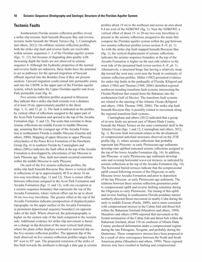
Fi
gure
14.
com
pres
sion
al a
ntic
linal
upl
ift, t
runc
ated
sei
smic
-ref
lect
ion
term
inat
ions
at t
he u
pper
bo
undi
ng s
eque
nce
boun
dary
of t
he lo
wer
Arc
adia
form
atio
n, a
nd d
ownl
appi
ng
refle
ctio
ns a
ssig
ned
to u
pper
Plio
cene
or l
ower
Ple
isto
cene
sed
imen
ts.

Geologic Structure of the Floridan Aquifer System 23
structures on the southeastern part of the Florida Platform. Reverse-fault movement sometime between the Oligocene to early Pleistocene is compatible with the timing of tectonic movement of the Santaren anticline (Southern Santaren Channel, Great Bahama Bank) reported by Masaferro and others (1999, 2002). To the east of the Florida Platform, Mulder and others (2013) reported observations that are consistent with late Cenozoic westward tectonic tilting on the Little Bahama Bank, which is temporally compatible with
of the uplift and movement along these reverse faults is also consistent with the occurrence of a widespread compressional event in the late Miocene and early Pliocene that Missimer and Maliva (2004) proposed as the source of folding in southern Florida. This compressional event could have generated reverse faulting throughout southern Florida. Missimer and Maliva (2004) attribute tectonic deformation in southern Florida to episodic interactions between the Caribbean and North American plates southeast of the Florida Platform. Alter-natively, it is possible that compressional uplift and reverse
movement along the Sunniland strike-slip fault system (Klit-gord and others, 1984; McClay and Bonara, 2001). Finally, it is possible the timing of the movement along the reverse faults beneath the Miami Terrace coincides with middle Miocene to early Pliocene movement along the strike-slip fault mapped beneath Biscayne Bay.
Buried Karst Collapse
karst collapse structures in Biscayne Bay using marine
(Cunningham, 2013; Reese and Cunningham, 2013, 2014) and data collected in 2011 across the southeastern Florida
F). This body of evidence supports the assertion that karst collapse structures are common structural features beneath southeastern peninsular
400 ft to approximately 3 mi in diameter. The structures identi-
These patterns characterize physical features, as indicated by
Although no karst collapse structures were observed
(Klimchouk, 2000) karst collapse and probable associated fault movement within a collapse structure in the carbonate Oldsmar Formation and lower part of the Avon Park Formation is evident above fractured, highly disturbed strata, and breccias that correspond to cave facies 3 and 4 of Loucks and others
interpreted as vertically coalesced, collapsed paleocaves (pl. 2). Other evidence for karst collapse includes borehole geophysical log signatures (Ronald S. Reese, U.S. Geological Survey, written commun., 2009) that indicate highly fractured rock, and vertical offset of geophysical log markers at the
(pl. 2). High travel times measured on borehole sonic log data
probably due to cycle skipping and indicate highly fractured
does enlarged caliper measurements well beyond the drilled borehole diameter (Ronald S. Reese, U.S. Geological Survey, written commun., 2009; pl. 2). These borehole geophysical log data and borehole video data show that fractured and disturbed strata associated with the collapsed caves span a vertical interval of about 900 ft from the top of the Boulder
larger collapsed paleocave system, located in the lower part
karst collapse structures in carbonate rocks that have similar physical characteristics to the structures delineated in the Flor-
and Walker (2009), Cunningham and others (2012), Cunningham (2013), and Reese and Cunningham (2013, 2014). Karst collapse structures outside of southeastern Florida include examples located in (1) northeastern Florida (Kindinger and others, 2000; Spechler, 2001), (2) the La Belle area of the Caloosahatchee River (Cunningham and others, 2001b), (3) Tampa Bay and Charlotte Harbor in
Hine, 1991; Hine and others, 2009), (4) the northeast Florida
serve as comparative analogs that provide clues about the
Texas (Loucks, 1999); Middle Ordovician dolomite and
and Miocene limestone in the South China Sea (Story and
studies also serve as excellent analogs. For example, the study
and Upper Ordovician Montoya Group in western Texas.
Texas (Kerans, 1988; Loucks, 1999; Loucks and others, 2004) are also useful analogs to collapse structures observed in the subsurface of southeastern Florida.

24 Seismic-Sequence Stratigraphy and Geologic Structure of the Floridan Aquifer System
Summary and ConclusionsThis report presents a seismic-sequence stratigraphic and
near the North and South District “Boulder Zone” Well Fields and guides the interpretation using analogs from nine seismic-
understanding of the seismic structures and seismic-sequence
-
the north and east of the North District “Boulder Zone” Well
-
References Cited
-
-
in
-

References Cited 25
Budd, D.A., Saller, A.H., and Harris, P.M., eds., 1995, Uncon-formities and porosity in carbonate strata: Tulsa, Okla., American Association of Petroleum Geologists Memoir 63, 313 p.
systems: American Association of Petroleum Geologists
--
cayne Landing groundwater remediation system: Report
-stone of Florida: Geological Society of America Proceed-
sequence-stratigraphic methods to characterize the hydro-geology of the Floridan aquifer system in southeast Florida:
L.A., and Reese, R.S., 2001a, Lithostratigraphy, sequence stratigraphy and biostratigraphy of a carbonate ramp and bounding siliciclastics (Late Miocene-Pliocene), southern Florida: Florida Geological Survey Special Publication 49,
and Barron, J.A., 2001b, Surface-geophysical characteriza-
Basin, southern Florida: U.S. Geological Survey Water-
Barron, J.A., and Guertin, L.A., 2003, Interplay of Late
the southeast Florida Platform: Journal of Sedimentary
P.F., Scott, T.M., and de Verteuil, Laurent, 1998, New Ter-tiary stratigraphy for the Florida Keys and southern pen-insula of Florida: Geological Society of America Bulletin,
-tures in Tertiary carbonate rocks beneath southeastern Florida, USA—Evidence for hypogenic speleogenesis?, in
-leogenesis and Karst Hydrogeology of Artesian Basins: Simferopol, Ukraine, Ukrainian Institute of Speleology
October 3, 2014, at http://institute.speleoukraine.net/
.
-
Floridan aquifer system, southeastern Florida: Society of Exploration Geophysicists Annual Meeting, Las Vegas, NV, 6 p., accessed October 3, 2014 at http://library.seg.org/doi/abs/10.1190/segam2012-0638.1.
southern Appalachian orogen and Atlantic-Gulf coastal plains and their correlations with West African sequences, in Dallmeyer, R.D., ed., Terranes in the circum-Atlantic Paleozoic orogens: Geological Society of America Special
2010, Hypothesis testing of buoyant plume migration using a highly parameterized variable-density groundwater model at a site in Florida, USA: Hydrogeology Journal, v. 18,
Duncan, J.G., Evans, W.L., III, Aylor, J.G., and Li, Li, 1994, Geologic framework of the Lower Floridan aquifer sys-
submitted to the Florida Department of Environmental Protection Bureau of Drinking and Ground Water Resources
El Awawdeh, R., Khouri, N., Al Neyadi, A., Shevchek, Z.J.,
Engineers, SPE 118006, 13 p.
Enos, P., and Perkins, R.D., 1977, Quaternary sedimentation of South Florida: Geological Society of America Memoir 147, 198 p.
stratigraphy of a carbonate-siliciclastic transition—South-west Florida: Geological Society of America Bulletin:
resolution seismic expression of karst evolution within
Guertin, L.A., Missimer, T.M., and McNeill, D.F., 2000, Hiatal duration of correlative sequence boundaries from Oligocene—Pliocene mixed carbonate/siliciclastic sediments of the south
seismic evidence of the effects of carbonate karst collapse on overlying clastic stratigraphy and reservoir compartmen-

26 Seismic-Sequence Stratigraphy and Geologic Structure of the Floridan Aquifer System
Heggland, R., 1997, Detection of gas migration from a deep source by the use of exploration 3D seismic data: Marine
data set, in Eberli, G.P., Masaferro, J.L., and Sarg, J.F., eds., Seismic imaging of carbonate reservoirs and systems: American Association of Petroleum Geologists Memoir 81,
-
that formed the sunshine state: Gainesville, Florida, Univer-sity of Florida Press, 230 p.
Duncan, D.S., Evans, M., and Morton, R.A., 2009, Karst subbasins and their relationship to the transport of Tertiary siliciclastic sediments on the Florida Platform, in Swart, P.K., Eberli, G.P., and McKenzie, J., eds., Perspectives in sedimen-tary geology—A tribute to the career of Robert N. Ginsburg: Oxford, Wiley-Blackwell, International Association of Sedi-
Horton, J.W., Drake, A.A., Jr., Rankin, D.W., and Dallmeyer, R.D., 1991, Preliminary tectonostratigraphic terrane map of the central and southern Appalachians: U.S. Geological
scale 1:2,000,000, 1 sheet.
James, N.P., 1997, The cool-water carbonate depositional realm, incarbonates: Society for Sedimentary Geology Special Publi-
in Ellenburger Group carbonates of west Texas: Ameri-can Association of Petroleum Geologists Bulletin, v. 72,
Kindinger, J.L., Davis, J.B., and Flocks, J.G., 2000, Subsur-face characterization of selected water bodies in the St. Johns River Water Management District, northeast Florida:
Klimchouk, Alexander, 2000, Speleogenesis under deep-seated in
Palmer, A.N., and Dreybodt, Wolfgang, eds., Speleogenesis evolution of karst aquifers: National Speleological Society,
Klitgord, K.D., Popenoe, P., and Schouten, H., 1984, Flor-ida—A Jurassic transform plate boundary: Journal of Geo-
in seismic data—Implications for fault seal analysis: Basin
Loucks, R.G., 1999, Paleocave carbonate reservoirs—Origins,
implications: American Association of Petroleum Geolo-
Loucks, R.G., Mecher, P.K., and McMechan, G.A., 2004, Three-dimensional architecture of a coalesced, collapsed paleocave system in the Lower Ordovician Ellenburger Group, central Texas: American Association of Petroleum
Lucia, F.J., 1995, Lower Paleozoic cavern development, collapse, and dolomitization, Franklin Mountains, El Paso, Texas, in Budd, D.A., Saller, A.H., and Harris, P.M., eds., Unconformities and porosity in carbonate strata: American Association of Petroleum Geologists Memoir 63,
in-
ogy: Society of Exploration Geophysicists, Geophysical
Maliva, R.G., Guo, W., and Missimer, T., 2007, Vertical migration of municipal wastewater in deep injection well systems, South Florida, USA: Hydrogeology Journal, v. 15,
Masaferro, J.L., Bulnes, M., Poblet, J., and Eberli, G.P., 2002, Episodic fold uplift inferred from the geometry of syntec-tonic carbonate sedimentation—The Santaren anticline,
Masaferro, J.L., Poblet, J., Bulnes, M., Eberli, G.P., Dixon, -
ent day(?) growth folding in the Bahamian foreland of the -
-ing stepovers in strike-slip fault systems: American Associa-
McDonnell, A., Loucks, R.G., and Dooley, T., 2007, Quan-tifying the origin and geometry of circular sag structures in northern Fort Worth Basin, Texas—Paleocave collapse, pull-apart fault systems, or hydrothermal alteration?: Ameri-can Association of Petroleum Geologists Bulletin, v. 91,
-tion, drilling and testing of 7 Upper Floridan monitor wells

References Cited 27
Miami-Dade Water and Sewer Department, 2002, Drilling
-
Miller, J.A., 1982, Structural control of Jurassic sedimentation in Alabama and Florida: American Association of Petroleum
Miller, J.A., 1986, Hydrogeologic framework of the Floridan aquifer system in Florida and in parts of Georgia, Alabama,
Miller, J.A., 1990, Ground water atlas of the United States—
U.S. Geological Survey Hydrologic Investigation Atlas
Missimer, T.M., and Gardner, R.A., 1976, High-resolution
Missimer, T.M., and Maliva, R.G., 2004, Tectonically induced
-
Mitchell-Tapping, H.J., Bellucci, J.R., Woody, G., and Lee, T.J., 1999, Mud Hole—A unique warm-water spring,
-
Mitchum, R.M., Jr., Vail, P.R., and Thompson, S., III, 1977, Seismic stratigraphy and global changes of sea level, Part
in depositional sequences: instratigraphy—Applications to hydrocarbon exploration: American Association of Petroleum Geologists Memoir 26,
morphology on a modern carbonate slope of the Baha-mas—Evidence of regional tectonic tilting: Geology, v. 40,
American Association of Petroleum Geologists Studies in Geology 58, 73 p.
of southern Florida, with a discussion of the ground water: Florida Geological Survey Bulletin 27, 119 p.
Banks Gigaplatform, northern margin of the Jurassic Proto-
Pomar, L., 2001, Types of carbonate platforms—A genetic
Popenoe, P., Kohout, F.A., and Manheim, F.T., 1984, Seismic-
features on the northeastern Florida shelf, in B.F. Beck, ed., Sinkholes—Their geology, engineering, and environmental
Puri, H.S., and Winston, G.O., 1974, Geologic framework of high transmissivity zones in south Florida: Florida Bureau of Geology Special Publication 20, 101 p.
Reese, R.S., 1994, Hydrogeology and the distribution and ori-gin of salinity in the Floridan aquifer system, southeastern Florida: U.S. Geological Survey Water-Resources Investiga-
stratigraphic and hydrogeologic cross sections and seismic
1141, 10 p., accessed October 3, 2014, at http://pubs.usgs.gov/of/2013/1141.
framework and salinity distribution of the Floridan aquifer
April 8, 2014, at http://pubs.usgs.gov/sir/2014/5029/.
Reese, R.S., and Richardson, E., 2008, Synthesis of the hydrogeologic framework of the Floridan aquifer system and delineation of a major Avon Park permeable zone in central and southern Florida: U.S. Geological Survey
Roberts-Ashby, T., Stewart, M.T., and Ashby, B.N., 2013, An evaluation of porosity and potential use for carbon
-
and southern Florida: Environmental Geosciences, v. 20,
-
Schlager, W., 1989, Drowning unconformities on carbonate platforms, in
development: Society of Economic Paleontologists and
Schlager, W., 1999, Type 3 sequence boundary, in Har-ris, P.M., Saller, A.H., and Simo, J.A., eds., Advances in carbonate sequence stratigraphy: application to reservoirs, outcrops and models: Society of Economic Paleontologists

28 Seismic-Sequence Stratigraphy and Geologic Structure of the Floridan Aquifer System
Scott, T.M., 1988, The lithostratigraphy of the Hawthorn Group (Miocene) of Florida: Florida Geological Survey Bulletin 59, 148 p.
Smith, D.L., and Lord, K.M., 1997, Tectonic evolution and geophysics of the Florida basement, in Randazzo, A.F., and Jones, D.S., eds., The geology of Florida: Gainesville,
Spechler, R.M., 2001, The relation between structure and salt-water in the Floridan aquifer system, northeastern Florida, in U.S. Geological Survey Karst Interest Group Proceed-ings: U.S. Geological Survey Water-Resources Investiga-
Saline water intrusion from deep artesian sources in the
carbonate reservoir developed using ultrahigh-resolution -
M., 2006, Application of new seismic attributes to collapse chimneys in the Fort Worth Basin: Geophysics, v. 71, no. 4,
Thomas, W.A., 1988, Early Mesozoic faults of the northern -
tic Ocean, in Maspeizer, W., ed., Triassic-Jurassic rifting:
Thomas, W.A., 2006, Tectonic inheritance at a continental
U.S. Environmental Protection Agency, 2013, Water: Under-
.
Walsh, V., and Price, R.M., 2010, Determination of vertical and horizontal pathways of injected fresh wastewater into a deep saline aquifer (Florida, USA) using natural chemical
J.B., and Ding, Z.-D., 1996, A Neogene mixed siliciclastic and carbonate foundation for the Quaternary carbonate shelf, Florida Keys: Journal of Sedimentary Research, v. 66,

Manuscript approved January 27, 2015
Prepared by the Raleigh Publishing Service CenterMichael Deacon, EditorKimberly Swidarski, Illustrations and layout
For more information about this publication, contact:Director U.S. Geological SurveyCaribbean-Florida Water Science Center4446 Pet Lane, Suite 108Lutz, FL 33559(813) 498-5000
or visit our Web site athttp://fl.water.usgs.gov

Cunningham—
Seismic-Sequence Stratigraphy and G
eologic Structure of the Floridan Aquifer System
—Scientific Investigations Report 2015–5013
ISSN 2328-0328 (online)http://dx.doi.org/10.3133/sir20155013