SEISMIC RESPONSE OF OFF-SHORE WIND TURBINES …1 SEISMIC RESPONSE OF OFF-SHORE WIND TURBINES FOUNDED...
12
1 SEISMIC RESPONSE OF OFF-SHORE WIND TURBINES FOUNDED ON MONOPILES OR SUCTION CAISSONS: A COMPARISON Rallis KOURKOULIS 1 , Ioannis ANASTASOPOULOS 2 ,Fani GELAGOTI 3 , Petros LEKKAKIS 4 , Olga-Lida CHRISTOU 5 , and George GAZETAS 6 The paper presents a comparative study on the response of offshore wind turbines founded on suction caissons or monopiles by means of non-linear three dimensional finite element analyses. The models are subjected to cyclic and earthquake loading taking account of the role of soil –foundation adhesion. In the case of monotonic and slow cyclic lateral loading it is shown that low adhesion interface could reduce the moment capacity and may lead to foundation detachment . The second part of the study evaluates the response of a soil–foundation–wind turbine system subjected to earthquake shaking. Results are shown for a 3.5MW turbine founded on either foundation type. Although the seismic effects are often considered insignificant when evaluating the seismic behavior of large offshore wind turbines on the basis of spectral characteristics, the current study reveals that in fact the system kinematics may prove crucial for their response as such systems are subjected to simultaneous environmental and seismic loads. Foundation tends to accumulate rotation which may not be instantly catastrophic but could lead to the turbines reaching their serviceability limits much earlier than expected during their operation. INTRODUCTION Installation of wind-farms of significant turbine capacities is planned with increasing frequency worldwide and, since the availability of on-shore locations may be limited, off-shore wind-parks are nowadays commonly adopted as viable alternatives. The challenge for the design of their foundation is to safely assume large overturning moments under comparatively low vertical loading (Houlsby& Byrne, 2000). Yet, in contrast to common offshore structures such as oil and gas structures, in case of wind turbines the foundation may account for up to 35% of the installed cost, thus its design may become crucial to the financial feasibility of the project. Among the several foundation types currently implemented in medium depth waters, the monopile option dominates the industry. The alternative examined here is a recently introduced scheme termed “suction caisson” which was originally proposed for the foundation of off -shore oil platforms. It comprises a shallow footing whose capacity is enhanced by means of peripheral embedded skirts which confine the internal soil thereby creating a soil plug. Installation process consists of floating the caisson to its location where it is driven into the seabed under the action of its self-weight and pumping of water trapped within the skirts thereby producing differential pressure which attracts the caisson lid downwards until it attains full contact with the soil. 1 Post Doctoral Researcher, NTUA, Athens, [email protected] 2 Professor, University of Dundee, Dundee, [email protected] 3 Post Doctoral Researcher, University of Patras, Patras, [email protected] 4 Post Graduate Researcher, Stanford University, Palo Alto, [email protected] 5 Civil Engineer, MSc,Atkins, London, [email protected] 6 Professor, NTUA, Athens, [email protected]
Transcript of SEISMIC RESPONSE OF OFF-SHORE WIND TURBINES …1 SEISMIC RESPONSE OF OFF-SHORE WIND TURBINES FOUNDED...
1
SEISMIC RESPONSE OF OFF-SHORE WIND TURBINES FOUNDED
ON MONOPILES OR SUCTION CAISSONS: A COMPARISON
Rallis KOURKOULIS1, Ioannis ANASTASOPOULOS
2,Fani GELAGOTI
3,
Petros LEKKAKIS4, Olga-Lida CHRISTOU
5, and George GAZETAS
6
The paper presents a comparative study on the response of offshore wind turbines founded on suction
caissons or monopiles by means of non-linear three dimensional finite element analyses. The models
are subjected to cyclic and earthquake loading taking account of the role of soil–foundation adhesion.
In the case of monotonic and slow cyclic lateral loading it is shown that low adhesion interface could
reduce the moment capacity and may lead to foundation detachment. The second part of the study
evaluates the response of a soil–foundation–wind turbine system subjected to earthquake shaking.
Results are shown for a 3.5MW turbine founded on either foundation type. Although the seismic
effects are often considered insignificant when evaluating the seismic behavior of large offshore wind
turbines on the basis of spectral characteristics, the current study reveals that in fact the system
kinematics may prove crucial for their response as such systems are subjected to simultaneous
environmental and seismic loads. Foundation tends to accumulate rotation which may not be instantly
catastrophic but could lead to the turbines reaching their serviceability limits much earlier than
expected during their operation.
INTRODUCTION
Installation of wind-farms of significant turbine capacities is planned with increasing frequency
worldwide and, since the availability of on-shore locations may be limited, off-shore wind-parks are
nowadays commonly adopted as viable alternatives. The challenge for the design of their foundation is
to safely assume large overturning moments under comparatively low vertical loading (Houlsby&
Byrne, 2000). Yet, in contrast to common offshore structures such as oil and gas structures, in case of
wind turbines the foundation may account for up to 35% of the installed cost, thus its design may
become crucial to the financial feasibility of the project.
Among the several foundation types currently implemented in medium depth waters, the
monopile option dominates the industry. The alternative examined here is a recently introduced
scheme termed “suction caisson” which was originally proposed for the foundation of off-shore oil
platforms. It comprises a shallow footing whose capacity is enhanced by means of peripheral
embedded skirts which confine the internal soil thereby creating a soil plug. Installation process
consists of floating the caisson to its location where it is driven into the seabed under the action of its
self-weight and pumping of water trapped within the skirts thereby producing differential pressure
which attracts the caisson lid downwards until it attains full contact with the soil.
1Post Doctoral Researcher, NTUA, Athens, [email protected]
2Professor, University of Dundee, Dundee, [email protected]
3Post Doctoral Researcher, University of Patras, Patras, [email protected]
4 Post Graduate Researcher, Stanford University, Palo Alto, [email protected]
5 Civil Engineer, MSc,Atkins, London, [email protected]
6 Professor, NTUA, Athens, [email protected]

2
Based on this background, the scope of this paper is to compare the response of wind turbines
founded on suction caissons or monopiles and subjected to lateral monotonic, cyclic and earthquake
loading (Fig. 1).
Figure 1. Schematic view of the two foundation alternatives : a circular suction caisson of diameter B and
embedded length D and a monopile foundation of length L.
PROBLEM DEFINITION – SOIL AND STRUCTURE MODELING
The analyses for the investigation of the problem were conducted in three-dimensional space using the
finite element code ABAQUS. Due to the symmetrical nature of the problem, only half of the
geometry has been modeled. The mesh used for the analyses is shown in Figure 2.
The soil body is modeled using 8-node hexahedral continuum elements (C3D8), obeying to a
kinematic hardening constitutive model with Von Mises failure criterion (Anastasopoulos et al, 2012).
The ratio of Eo/Su where Eo the elastic modulus for zero plastic strain was assumed equal to 1000.
A homogeneous soil deposit has been assumed for both cases with an undrained shear strength equal
to Su = 60 kPa. (Figure 2b). The soil submerged specific weight is γ' = 10 kN/m3. The wind turbine is
modeled as a tower with distributed mass and a concentrated mass on the top that represents the rotor-
nacelle assembly.
Its tower is modeled using linear elastic beam elements with an elastic modulus equal to half the
modulus of the steel (E' = Es/2 = 105 GPa), and its section inertia as the normal inertia of the fully
modeled tower, so that the stiffness of the model tower (EI)' = EI/2.
The foundation (suction caisson or monopile) is modeled with linear elastic shell elements. Its elastic
modulus and density have the usual values of steel; Es = 210 GPa and πs = 7.85 t/m3. Unless otherwise
stated, the element thickness is equal to ts = 0.02 m. The caisson lid element thickness is taken tl = 0.5
m, which is sufficient to make it behave as practically rigid, given the high value of Young's modulus
of steel (in practice this is achieved with the use of appropriately designed stiffeners).
In order to simulate as realistically as possible the contact conditions between the foundation and the
surrounding and encased soil, contact elements are introduced. As implied already, the assumption of
fully tied interface between the foundation and the soil may not be always justified (e.g. due to
shearing during driving). Since it is impossible to estimate the proportion of the residual interface
strength a priori, its effect is herein investigated parametrically by means of the following two
assumptions:
(i) In the first case fully bonded interface conditions are adopted
D
B
Wind
Waves
V M H
su
Wind
Waves
B
L
z
Suction caisson Monopile

R. Kourkoulis, I.Anastasopoulos, F. Gelagoti, P.Lekkakis, O.L. Christou, G. Gazetas 3
(ii) In the second case, the strength along the interface is assumed to be a fraction (a) of the undrained
shear strength of the soil. Based on centrifuge data, factor a has been taken equal to 0.6.
Figure 2. Finite element mesh of the wind turbine when founded on:
(a) a suction caisson and (b) a monopile.(c)Low adhesion conditions are assumed at the soil-foundation interface
for both foundation alternatives.
EFFECT OF INTERFACES ON BEARING CAPACITY
Both constant–ratio displacement probe tests and displacement controlled swipe tests were carried out
in order to produce the dimensionless moment-horizontal force interaction diagrams. Probe tests
consist of the application of constant ratio combinations (i.e. v/Bθ = const or h/Bθ = const) of rotation
x
z y
6B
2.5B
Shell elements
3D brick elements : Nonlinear Soil
Lumped mass (m)
Beam Elements
Beam Elements
Shell elements
Lumped mass (m)
(a)
(b)
τ
δ
α Su
Interface ( τmax )
Full contact
α Su
(c)

4
(θ) and vertical or horizontal displacement (v or h). They produce load paths which, commencing from
the origin, evolve until reaching failure. Note that the initial slope of the probe test load path depends
on the elastic stiffness but it is gradually modified as it moves towards the failure envelope as a result
of plastic yielding. Once the failure envelope is reached, each path tracks around it until a termination
point (Figs. 3a, 4) where the normal to the failure envelope matches the prescribed displacement ratio.
Figure 3. (a)M-H failure envelopes (for V=0) for a suction caisson with D/B=0.5 embedded in uniform clay of
undrained shear strength su : comparison of the failure envelope produced by means of swipe test (bold black
line) or displacement probe tests (grey line). The red line represents the failure envelope when low adhesion
conditions are assumed.; (b) The effect of interfaces on developed failure mechanism (the snapshot corresponds
to a suction caisson of D/B=1 subjected to pure Moment loading
Swipe tests (Tan, 1990) on the other hand, are a popular method to produce the failure envelope in H–
M space as they allow the generation of the complete failure envelope through one single analysis. An
initial rotational swipe is required to define the point of maximum moment while constraining the
horizontal translational degree of freedom. This is followed by a translational swipe in the opposite
direction to produce the part of the curve belonging to the negative quadrant.
The reader is encouraged to observe two key characteristics of the failure envelopes (Fig.3a):
(a) In both systems, the maximum moment capacity (Mmax) is mobilised under a combination of
positive horizontal load and moment, rather than pure moment only (Mo ) while similarly the
maximum horizontal force (Hmax) is also a product of coupled horizontal load and moment and larger
than the pure horizontal load (Ho)
(b) The response in the H-M space for both foundations is clearly non-symmetric: the combination
of horizontal and moment load acting in the same direction (HM positive) is not physically equivalent
0
0.5
1
1.5
2
-4 -2 0 2 4
Swipe test
Probe tests Failure envelope (by probes) M / ABsu
-0.5
0.1 0.25
0.5
1.0
2.0
3
2
1
0 -8 -4 0
u/Bθ = -1
u/Bθ = 10
4 8
H / ABsu
D
u
θ
V = 0
Su
B
(a)
(b)
Full Adhesion
Mo
Mo
Low Adhesion
R. Kourkoulis, I.Anastasopoulos, F. Gelagoti, P.Lekkakis, O.L. Christou, G. Gazetas 5
to the foundation response when they act in the opposite direction (HM negative). However, for the
sake of clarity, most of the diagrams presented in the sequel will refer to the positive quadrant (HM
positive).
(c) When considering the suction caisson, the assumption of low-adhesion interface inevitably
results in annulation of the shearing resistance offered by the part of the sidewalls opposite to the
direction of displacement. As such, moment may be transmitted to the soil through the soil-lid
interface (considered fully bonded throughout this paper) as well as the normal and shear stresses
developed at the part of the skirt lying in the same direction as the loading which is therefore unable to
detach; naturally, this results in lower resistance than the one under full contact conditions. Hence, the
failure envelopes tend to contract with respect to their original shape (Fig. 3a red line).
(d)For shallow suction caissons, the assumption of low-adhesion conditions at the soil-foundation
interface practically conceals the differences between pure (Hoor Mo) and maximum (Hmax or Mmax)
ultimate capacity, while at the monopile system a rather isotropic shrinkage of the failure loci takes
place.
In an attempt to illustrate the mechanism behind this response, Figure 3b plots the plastic strain
contours at the instant of maximum pure moment for the case of suction caissons. The snapshots refer
to a deeply embedded caisson where the developed mechanisms are more clearly recognizable.
Evidently, when full contact is ensured, the caisson-internal soil system merges into one quasi-solid
caisson whose reaction results in the formation of a deep scoop failure mechanism similar to the one
identified by Bransby & Yun, 2009). The scoop-wedge mechanism remains the prevailing mode of
failure under pure moment (Mo) loading with the only difference being the absence of the top wedge
on the rear side of the foundation due to detachment from the sidewalls. This is reflected in the quite
insignificant reduction (of the order of 20%) of the Mo value with respect to the fully-bonded
conditions. Of course, as already explained this is not the case in terms of Mmax.
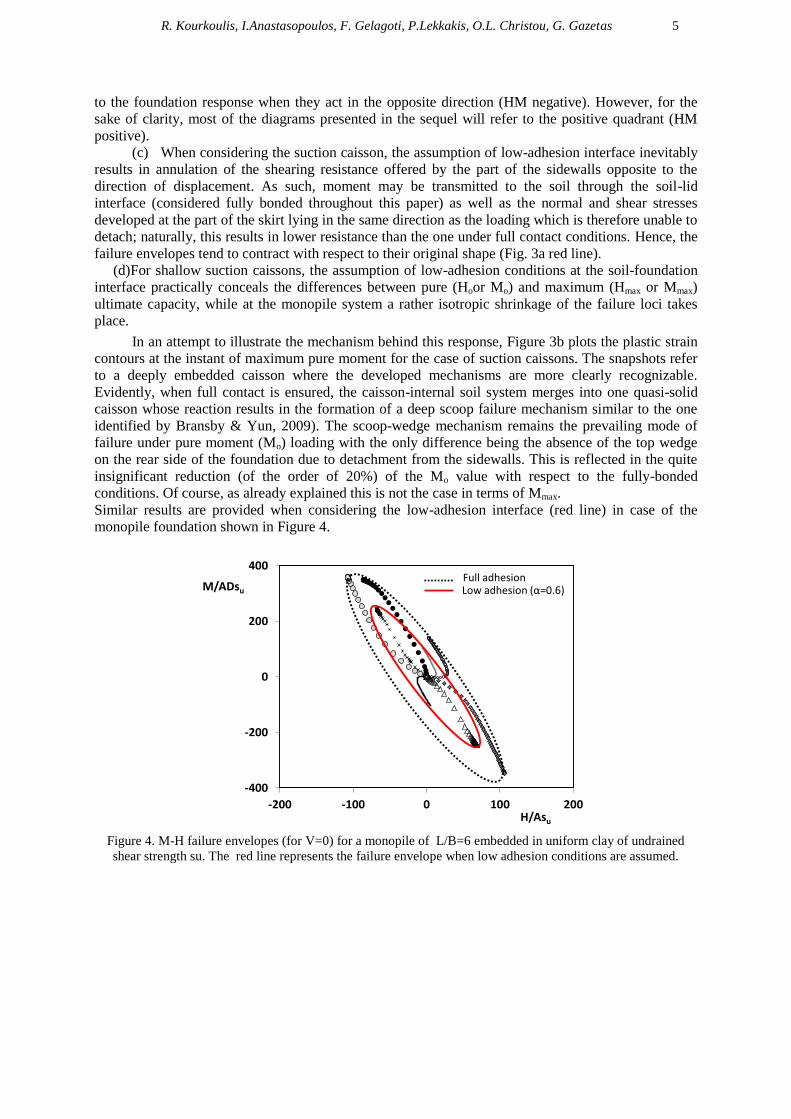
Similar results are provided when considering the low-adhesion interface (red line) in case of the
monopile foundation shown in Figure 4.
Figure 4. M-H failure envelopes (for V=0) for a monopile of L/B=6 embedded in uniform clay of undrained
shear strength su. The red line represents the failure envelope when low adhesion conditions are assumed.
-400
-200
0
200
400
-200 -100 0 100 200
M/ADsu
H/Asu
Full adhesion Low adhesion (α=0.6)

6
Figure 5. (a) M-H envelopes for the monopile (left) and the suction caisson foundation (right). Two embedment
ratios for each case are examined: L/B =6 (black line) and L/B =4 (gray line) for the monopile and D/B=0.5
(black line) and D/B=0.2 (gray line) for the suction caisson. Effect of embedment ratio on the ultimate
resistance: (b) monopile subjected to pure horizontal loading (Ho) and (c) suction caissons subjected to pure
moment loading (Mo).
EFFECT OF EMBEDMENT DEPTH
In order to facilitate a direct comparison of the foundation capacity of the two alternatives, Figure 5
presents the failure loci ( in absolute terms) and the corresponding displacement. Two suction
750
500
250
0
Μ : ΜNm
H : MN
25 50 100 0 25 50 100 0
H : MN
Mult ≈ 400 MNm pile
Ho H’o
Mo
M’o
Σημείο περιςτροφήσ
Interface
Center of rotation Center of rotation
gap at bottom
u u
H’o
Area of interest for wind-turbines 2-3.5 MW Mult ≈ 550 MNm
suction
M’ult ≈ 350 MNm
Ho
(a)
(b)
M H
V=0
M H
V=0
(c)
M’o Mo

R. Kourkoulis, I.Anastasopoulos, F. Gelagoti, P.Lekkakis, O.L. Christou, G. Gazetas 7
caissons (of D=20m) and D/B = 0.2 and 0.5 respectively are compared against two monopile
foundations of B=5m and L/B=4 or 6. The following key observations emerge:
(a) The ultimate moment capacity offered by the suction caisson of D=20m and D/B=0.2 is
comparable to the capacity achieved with a monopile of D=5 m and D/L=6.
(b) By slightly increasing the skirt length of the suction caisson to D/B=0.5 instead of D/B=0.2, a
much improved response may be achieved : the ultimate capacity is increased from 350 to 550 MNm.
(c) For shallowly embedded caisson, the failure mode at Μο load state resembles a “retina” shaped
mechanism. Due to reduced shear resistance at the caisson periphery, the internal soil is mobilized
even under low-amplitude of imposed rotation forming the characteristic inverted scoop between the
skirts.
(d) The L/D=4 (short) monopile responds to the imposed displacement through rotation as a rigid
system with its pole of rotation lying at its bottom edge. No flexural bending is developed. On the
other hand, the long L/B=6 monopile represents a flexible system which develops considerable
flexural bending. Plastic deformations are now developing on the upper part of the pile only, while the
pole of rotation is translated higher within its body.
RESPONSE UNDER SERVICE LOADS
Having identified the main mechanisms governing the response of the foundations to monotonic
loading, this section is devoted to the behaviour of a typical 3.5 MW wind turbine on suction caissons
or monopiles to service loads. The same pairs of foundations are compared in order to identify the
advantages and drawbacks of each system and which -if any- are comparable in terms of
superstructure response. Note that all analyses refer to the low-adhesion (conservative) scenario.
Response to environmental loading
The first step of the analyses entailed the application of dead loads to the model. This was followed by
a second loading step consisting of the application of wind load, modelled as a constant horizontal
force on the level of the rotor, and a third step containing cycles of pseudo-statically imposed wave
force. Based on literature data , the adopted amplitude values of wind and wave loads acting on the 3.5
MW turbine were taken as:
Wind Load: a constant force of 1 MN, acting on the level of the rotor-nacelle assembly (80 m
from mud-line)
Wave Load: 10cycles of applied force of amplitude1 ± 2 MN, acting at a height of approximately
7.8 m from the mud-line
Figure 6 plots the moment-rotation and settlement-rotation diagrams at the foundation level for all the
cases examined. Among the three types of foundations, the L/B = 4 monopile clearly exhibits the
largest values for rotation as well as incremental rotations. All but the D/B=0.5 caisson seem to
display a tendency to accumulate some rotation with increasing number of cycle. This accumulation
could cause some systems to exceed the serviceability rotation limit, a fact that, expectedly, would
deem them insufficient to support a typical 3.5 MW wind turbine and should be checked at the design
stage. However, as already mentioned the focus of this part of our study is to rather identify which two
systems (i.e one monopile and one suction-caisson foundation) offer equivalent results in terms of
superstructure response in order to proceed to the investigation of their response under seismic
loading. Under this prism and similar to the findings of the previous paragraph, the L/B=6 monopile
and the D/B=0.2 suction caisson will be carried forward to the next step since they provide
equivalence both in terms of rotation (initial and rotation per-cycle) and of settlement accumulation
during cyclic loading. Indeed, despite their difference in terms of moment capacity (evidenced by the
respective dotted curves), the two systems under the service loads develop an initial rotation of the
order of 1.5 x 10⁻³ rad which increases (albeit at a quite minute rate) during each loading cycle. The
same holds true in terms of settlements which remain lower than 2.5cm.

8
Figure 6. A 3.5 MW wind-turbine founded on a 5m monopile (left plots) with L/B =6 (black line) or
L/B =4 (gray line) and on a suction caisson (right plots) of B=20 m and D/B=0.5 (gray line) or D/B=0.2 (black
line) and is subjected to the design environmental loads [i.e. a constant wind load of 1000 kN and to a cyclic
Wave load of amplitude 2000 kN: (a) Moment-rotation and (b) settlement-rotation curves.
EARTHQUAKE LOADING
As already mentioned wind turbines are low frequency structures and as such their structural systems
are relatively insensitive to earthquake loading. Indeed, the first two eigenfrequencies of the
investigated 3.5MW turbine have been numerically estimated at fo = 0.275 Hz and f1 = 2.75 Hz
respectively.
However, the focus of this section will be on the investigation of the soil–foundation–
superstructure interaction which may be responsible for additional kinematic loading being imposed
on the system. To this end, the turbine -modelled as a 1-dof system consisting of a beam and a
concentrated mass at the rotor-nacelle level- has been assumed to be founded on the two previously
identified foundation alternatives: a B=20m, and D/B=0.2 suction caisson or a monopole with B=5m
and L/B=6. The initial elastic modulus over shear strength ratio, Eo/Su, was taken equal to 1800.
Proper kinematic constraints have been assumed at the lateral boundaries of the FE model to simulate
free-field response, while dashpot elements have been used at the base of the model to correctly
reproduce radiation damping (Fig. 7a). The hysteretic damping ratio of the soil stratum was taken as
ξs = 3%. Based on the IEC wind turbine design code; the adopted tower damping was equal to
-6.0
-5.0
-4.0
-3.0
-2.0
-1.0
0.0
0.000 0.002 0.004 0.006 0.008
G+Wind Application of Wave
θ: rad
M: MNm
w: cm
0
50
100
150
200
0.000 0.002 0.004 0.006 0.008
θinit. = 1.5 x 10⁻³
0
50000
100000
150000
200000
0 0.002 0.004 0.006 0.008
θinit. = 1.5 x 10⁻³
-0.06
-0.05
-0.04
-0.03
-0.02
-0.01
0
0 0.002 0.004 0.006 0.008θ: rad
D/B = 0.5D/B = 0.2
D/B = 0.5D/B = 0.2
(a)
(b)
1 MN
1 ± 2 MN
BD
1 MN
1 ± 2 MN
L
L/B = 6L/B = 4
L/B = 6L/B = 4

R. Kourkoulis, I.Anastasopoulos, F. Gelagoti, P.Lekkakis, O.L. Christou, G. Gazetas 9
ξt = 1%.The time history applied to the base of the model is defined as modified Rinaldi record (Fig.
7b and c) and has originated from the devastating Rinaldi accelerogram recorded during the
Northridge, 1994 earthquake. The record is characterized by a significant strong pulse followed by
minor cycles of lower amplitude and is considered as the moderate scenario practically compatible
with the EC8 design spectrum.
Loading is again imposed in three steps. During the first one, the dead loads are applied to the
model. This is followed by a second loading step consisting of the application of environmental loads,
and a third dynamic step during which the time history analysis is conducted.
Figure 7. The 3.5 MW wind-turbine subjected to earthquake loading: (a) Kinematic constraints at the sides nodes
of the model (allowing proper simulation of free-field soil response) and dashpots at the bottom nodes. (b) The
acceleration time-history at the soil surface and (c) at the nacelle level
Response to ground Shaking
The drift time histories (defined as the horizontal displacement at the nacelle level over the tower
height) are displayed in Figure 8a for both turbines. Observe that, independently of foundation type,
the turbine response is maintained within controllable limits while the maximum experienced
acceleration at its top is 0.25g (Fig. 7c). As anticipated, its oscillation is invariably out of phase with
the excitation time history. The turbine oscillates mainly in its first eigenmode; yet excitation of its
second mode is also evidenced by the "curly" shape of the acceleration time history.
In terms of foundation response it is evident that both alternatives tend to accumulate a non-
negligible rotation during each cycle (Fig. 8c). Although unexpected based on its spectral
characteristics, the long-period of the 3.5 MW turbine would not render it insensitive to ground
shaking when considering the whole foundation-structure system. On the contrary, the residual
rotation may be substantially increased with respect to its initial value; this reveals a potentially
seriously detrimental effect of environmental (wind and wave) loading acting concurrently with the
earthquake as explained in the next paragraph.
The role of inertial loading
Figure 9 plots the rotation time history on the foundation of the 3.5 MW turbine (bold line) subjected
to modified Rinaldiaccelerogramwhen the action of wind and waves are neglected. Apparently,
foundation rotation does occur; yet the rotation experienced during one cycle is recovered during the
next, resulting in practically negligible residual distortion. This response is actually consistent with the
previously mentioned anticipation as to the sensitivity of the wind turbine to inertial loading.
Remarkably, when considering the wind and current forces acting simultaneously with the earthquake
loading (Fig. 9 regular line), the developed rotation is not only irrecoverable, but rather keeps being
accumulated during each cycle.
dashpots
Seismic excitation
acc
-5
-2.5
0
2.5
5
0 5 10 15 20
acc : m/s2
0.4 g
t : s
(b) (a)
atur
-5
-2.5
0
2.5
5
0 3 6 9 12 15
atur : m/s2
t : s
(c)

10
Figure 8. Comparison of the seismic response of a 3.5 MW wind-turbine when founded on a suction caisson of
D=20 m and D/B=0.2 and when founded on a monopile of D=5 m and L/D=6: (a) drifttime history (defined as
ux/h) at the nacelle level and (b) (seismically accumulated) rotation time history at the foundation.
CONCLUSIONS
This paper has investigated the response of wind turbines founded on either monopiles or suction
caissons subjected to monotonic lateral, cyclic and earthquake loading with emphasis on the
parametric investigation of the role of soil-foundation interface strength. It is concluded that :
In terms of foundation capacity the consideration of low-adhesion conditions at the foundation-
soil interface allows sliding or even detachment of the foundation from the soil, which results in
a non-negligible decrease in the actual ultimate capacity of both foundation systems.
Under lateral monotonic loading the ultimate moment capacity that may be achieved by a
response of a suction caisson of D=20m and D/B=0.2 is comparable to the capacity offered by a
monopile of D=5 m and D/L=6.
The two alternatives (monopile and suction caisson) compare well in terms of stiffness
By increasing the skirt length of the suction caisson to D/B=0.5 instead of D/B=0.2, a much
improved response may be achieved : The ultimate capacity is increased form 350 to 550 MNm,
while the foundation responds practically elastically to the imposed cyclic loading (no
accumulation of rotation)
The response of the wind turbine to seismic shaking was assessed by subjecting it to a
moderately strong earthquake scenario originating from the recorded Rinaldi (1994)
t : s
6
4
0
[θ-θstat] x
10-3 rad
(a)
(b)
2
0
0.002
0.004
0.006
0 3 6 9 12 15
0
0.002
0.004
0.006
0 3 6 9 12 15
0
1
2
3
-1 4 9 14 19
Seismic loading Wind + Wave
0
1
2
3
-1 4 9 14 19t : s
t : s t : s
3.25
Drift %
2.5
1.25
h
ux Wind: 1MN
Wave : 2MN acc
Wind: 1MN
Wave : 2MN acc

R. Kourkoulis, I.Anastasopoulos, F. Gelagoti, P.Lekkakis, O.L. Christou, G. Gazetas 11
accelerogram. It was shown that due to its large flexibility, the superstructure is generally
insensitive to ground shaking. However, when the wind and current forces are acting
simultaneously with the earthquake loading the developed rotation at the foundation, is not only
irrecoverable, but rather keeps being accumulated during each cycle. The latter may not be
threatening the safety of the structure but produces irrecoverable distortion that may question
the serviceability of the turbine.
The seismic performance of the two foundation is practically equivalent : both the foundation
and the turbine accumulate similar deformations
Figure 9. Illustration of the role of unidirectional environmental loads for a 3.5MW turbine (on a suction caisson
with D=20m, L/D=0.5): seismic rotation time history at the foundation.
ACKNOWLEDGMENT
This research has been co-financed by the European Union (European Social Fund – ESF) and Greek national
funds through the Operational Program "Education and Lifelong Learning" of the National Strategic Reference
Framework (NSRF) - Research Funding Program: Thales. Investing in knowledge society through the European
Social Fund, Project ID "AIOLOS".
REFRENCES
ABAQUS 6.10. (2010). Standard user's manual. Dassault Systèmes Simulia Corp., Providence, RI, USA.
Anastasopoulos, I., Gelagoti, F., Kourkoulis, R. &Gazetas, G. (2012). Simplified Constitutive Model for
Simulation of Cyclic Response of Shallow Foundations: Validation against Laboratory Tests, Journal of
Geotechnical and Geoenv. Eng., ASCE, 137(12), 1154-1168.
Bransby, M. F. & Yun, G. J. (2009).The undrained capacity of skirted strip foundations under combined loading,
Geotechnique, 59 (2), 115-125.
Byrne, B.W., &Houlsby, G.T (2000).Foundations for offshore wind turbines, Phil. Trans. R. Soc. Lond. A
(2003) 361, 2909–2930.
Houlsby, G.T. & Byrne, B.W. (2000). Suction Caisson Foundations for Offshore Wind Turbines and
Anemometer Masts, Wind Engineering, 24(4), 249-255
House, A. R. & Randolph, M. F. (2001). Installation and pull-out capacity of stiffened suction caissons in
cohesive sediments, 11th
Intl. Offshore and Polar Eng. Conf., Vol. 2, ISBN 1-880653-2.
Ishibashi I. and X. Zhang, (1993), “Unified dynamic shear moduli and damping ratios of sand and clay”, Soils
and Foundations, Vol. 33(1), pp. 12-191.
2.0
1.0
0
-1.0
θ – θo : 10-3 rad
Without Envir. Loads
With Envir. Loads
t : s
Zero residual rotation
-0.001
0
0.001
0.002
0 5 10 150 5 10 15

12
Tan, F. S. C. (1990). Centrifuge and numerical modelling of conical footings on sand, PhD thesis, University of
Cambridge.
Vucetic M. and R. Dobry, (1991), “Effect of soil plasticity on cyclic response”, Journal of Geotechnical
Engineering, ASCE, Vol. 117(1), pp. 89–107.