seismic research - mdsys.co.kr research.pdf · • API 11P / API 618 Compressors (chemical and...
12
MOBILE SYSTEMS your high pressure solution www.lmf.at compressor systems for seismic exploration seismic research
Transcript of seismic research - mdsys.co.kr research.pdf · • API 11P / API 618 Compressors (chemical and...

MOBILE SYSTEMS
your high pressure solution
www.lmf.at
compressor systems for
seismic exploration
seismicresearch

companyprofile
LMF is the leading Austrian manufacturer of high-pressure piston compressor systems for air, natural gas, technical and industrial (process) gases.
These systems, with power rates from 20 to 6,200 kW (30 to 8,300 hp) and for pressures of up to 700 bar (10,150 psi), are designed and manufactured in accordance with internationally applicable standards.
LMF has over 60 years of experience in the production of compressors and offers its customers the benefits of the latest developments in design engineering, proven manufacturing methods, testing under full load, installation and after sales service, all from a single source.
LMF is well known worldwide as the manufacturer of:• API 11P / API 618 Compressors
(chemical and petrochemical industry)• Compound compressor systems
(mobile and stationary) for seismic research
• Compressors for many types of industrial applications
• CNG / CBG-systems
your high pressure solution2
LMF Headquarters in Leobersdorf, Austria
GEOGRAPHICAL POSITION
Leobersdorf is located approx. 30 km south of the capital of Austria, Vienna, and has direct access to the freeways, both to the city of Vienna and to the Vienna International Airport.
your high pressure solution3
contents
BASIC DESIGNS 04
OPTIONAL EQUIPMENT 05
COMPOUND SYSTEM 06
BENEFITS FOR CLIENTS 07
PROVEN MAIN COMPONENTS 08
APPLICATIONS 10
www.lmf.at

seismic exploration
basic designs
your high pressure solution4
SEISMIC EXPLORATION
is provided with air-gun systems (offshore). As energy sources high pressure compressors are in use.
The requirements for the compressors are, besides efficient performance, • low maintenance costs• availability• small dimensions and• low weight
LMF offers a wide range of capacities up to 78 m3 / min (2,755 cfm) and wor- king pressures up to 350 bar (5,076 psi) in stationary, portable and mobile design for offshore operation with electric motor or diesel engine as prime mover.
2 TO 6 M³ / MIN (70 TO 212 CFM) CAPACITY:Air-cooled piston compressors designed for continuous operation.
8 TO 20 M³ / MIN (282 TO 706 CFM) CAPACITY:Water-cooled piston compressors in cross-head design,combined with blower type feed compressors for minimum space requirements of the complete package.
21 TO 78 M³ / MIN (742 TO 2,755 CFM) CAPACITY:Compound systems as optimal solutions for highest capacities with smallest possible space requirements and weights.
A rotary screw compressor is used to feed the piston compressor with pre-compressed air. Both compressors are directly driven by a centrally located electric motor or diesel engine.
COOLING SYSTEMPiston compressors with capacities up to approx. 6 m3 / min (212 cfm) are available in air-cooled design. On request it is, however, possible to supply the inter- and after-coolers with water-cooling.
The prime mover can be air- or water-cooled. Larger piston compressors and compound compressor systems will be water-cooled. Prime movers (electric motors and diesel engines) are generally also water-cooled. It is a preferred modern design to have the compressor (piston or compound) cooled by a closed freshwater circuit with one fresh- / seawater heat exchanger (plate cooler). This system keeps the compressor unit „clean“ from seawater and makes a fast and easy heat exchanger maintenance possible.

seismic exploration
basic designs
your high pressure solution5
www.lmf.at
seismic exploration
optional equipment
AUXILIARY EQUIPMENT
All additional components such as relief valves, filters, pressure reservoirs etc. can also be supplied and integrated into the pressure control of the units by LMF as part of an overall concept.
OPTION 1: CAPACITY CONTROLFor larger capacities, e. g. 20m3 / min (707 cfm) and more, it is relevant to adjust the compressor capacity during operation to the actual demand in order to avoid blow-off air and save energy (fuel or electric).
LMF has developed an electronic control system for stepless capacity control in the range between 50 % and 100 % load by means of• frequency speed control of electric
driven units or• a combination of air inlet and engine
speed control of diesel driven units (reduction of fuel consumption up to 40 %, reduction of compressed air capacity 50 %)
OPTION 2: LMF PRESSURE CONTROL SYSTEM (LMF-PCS) Depending on the actual pressure in the high pressure reservoir, the system is controlling up to 4 compressor aggregates in an optimized way.
OPTION 3: GUN ARRAY MANIFOLDA manifold with all required locking and monitoring facilities is used to feed all airguns installed. In order to avoid pressure surges that might compromise operation safety, the locking fittings are operated pneumatically.
OPTION 4: PRESSURE RESERVOIR (BOTTLE RACK)High pressure air receiver consisting of one high pressure vessel with a volume of 500 ltr. or 4 up to 18 high pressure bottles, 63 ltr. each. Compact design and skid mounted package for ready to use installation at the main high pressure supply line. Necessary air storage when using automatic pressure control system (LMF-PCS).
OPTION 5: HIGH PRESSURE FILTERS2 double high pressure filters upstream to gun array manifold for clean high pressure supply to the air gun distribution. Rated pressure of high pressure filters: 250 bar.
OPTION 6: CONTAINERIZATIONAll compressor units are prepared to fit into containers, which are hot-zinc coated and painted. Additionally the containers are equipped with forced fan and all openings for proper operation on deck.
Pressure control: high pressure overview
your high pressure solution6
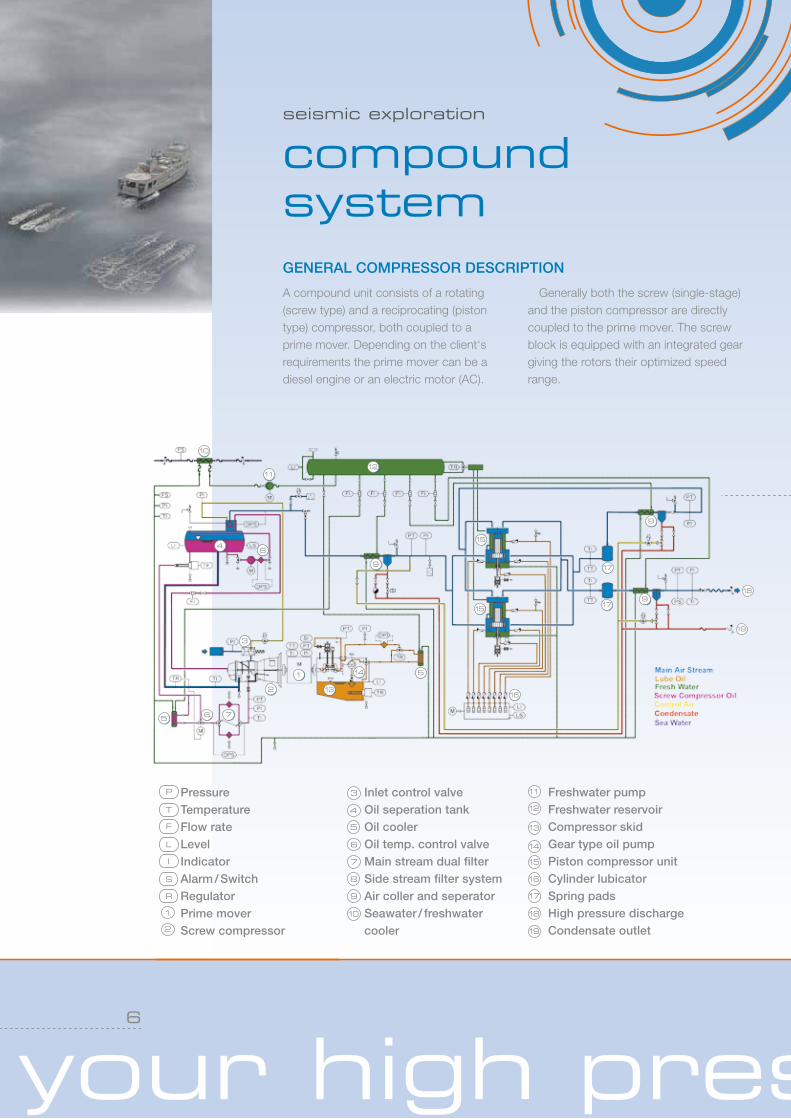
GENERAL COMPRESSOR DESCRIPTION
A compound unit consists of a rotating (screw type) and a reciprocating (piston type) compressor, both coupled to a prime mover. Depending on the client‘s requirements the prime mover can be a diesel engine or an electric motor (AC).
Generally both the screw (single-stage) and the piston compressor are directly coupled to the prime mover. The screw block is equipped with an integrated gear giving the rotors their optimized speed range.
PressureTemperatureFlow rateLevelIndicatorAlarm / SwitchRegulatorPrime moverScrew compressor
Inlet control valveOil seperation tankOil coolerOil temp. control valveMain stream dual filterSide stream filter systemAir coller and seperatorSeawater / freshwater cooler
Freshwater pumpFreshwater reservoirCompressor skidGear type oil pumpPiston compressor unitCylinder lubicatorSpring padsHigh pressure dischargeCondensate outlet
1
2
3
4
5
6
7
8
10
11
12
13
14
15
16
17
18
19
9
F
I
L
P
R
S
T
seismic exploration
compound system
1
2
3
4
5
5
6 7
8
10
9
9
9
1112
13
14
15
15
16
17
17
18
19

your high pressure solution7
www.lmf.at
seismic exploration
compound system
seismic exploration
benefits for clients COMBINED ADVANTAGES
The compound compressor combines the advantages of both rotating and recipro-cating systems. A screw block requires far less space than that taken by other low pressure systems. Single-stage oil-injected screw blocks replace two or three low pres-sure piston compressor stages. The piston compressor completes compression after the screw has reached the pressure limit imposed by its geometrical design. In this way, a single-stage screw combined with a two- or three-stage piston compressor for example, can substitute a conventional four- or five-stage reciprocating unit.
This allows for considerable reductions in weight and space. It is usually possible to achieve a 50 % decrease in the floor space required, further-more the number of compressor valves can be approximately reduced by half.
QUALITY AND COMPETENCECompound compressors are available for under deck installation or containerized for on-deck application. Compressor cooling is a closed, fresh water circuit with water (seawater) recooling. All machines are designed, manufactured and tested (under
full load) in accordance with the valid standards (such as DIN, DNV, VDI, VDE, IEC, ISO, etc.) and the LMF quality assurance system, which has been certified by BV (ISO 9001).
In addition, all units can be tested according to DNV, LRS, GL, BV, CCS etc., and relevant certificates (e. g. CE-certifi-cates) are submitted if required.
All LMF compressors are optimized based on our experience in having built more than 650 units since 1980, for clients all over the world.

your high pressure solution8
seismic exploration
proven main componentsPISTON COMPRESSOR
• Low-vibration and extremely compact design due to totally balanced “Boxer” design
• High efficiency at low compression temperatures due to crosshead (1) design and water-cooled cylinders (2)
• Direct coupling with prime mover up to 1800 rp
• Three-stage compression in 2 or 4 cylinder units at final pressures rates of 137 bar (2,000 psi) / 207 bar (3,000 psi)
• Minimal oil consumption and wear of piston rings due to high pressure mini-lubrication of the PTFE piston rings and guide rings
• Maximum possible lifetime of compressor valves (3), ensured by high quality PEEK plates
• Long working life of stuffing box packings, as not exposed to compressor final pressure
• Extremely long periods between gear oil changes due to high efficiency of oil cooling system
• Uncomplicated valve service with no dismantling of gas or water pipes
• Simple piston ring change due to easily removable high pressure cylinder units (4)
• Complete unit mounted on spring elements (four-point version)
Process gasCooling waterLube oil
3
3
5
4 22
4
3
5
3
32
1 1

your high pressure solution9
www.lmf.at
SCREW COMPRESSOR
• Single-stage, oil-injected unit• Simple, highly robust design• No wear and tear parts required• Working life of bearings at least
30,000 hours (at a final pressure rate of 15 bar / 218 psi)
• Roller bearings (1) absorb the radial forces, inclined ball bearings (2) the axial forces
• Superior efficiency through asymmetrical Sigma
• Profile of rotors; male rotor (3) five-lobed, smaller female rotor (4) six-lobed, oil-flooded
• Compressor housing (5) and shaft seal (6) pressure tight up to 15 bar (218 psi)
• Integrated single stage gear box (7); smoothness of running and low noise
guaranteed by ground and inclined gear wheels
• Generously proportioned transmission housing (8) suitable for coupling assembly; large inspection openings (9)
• Suction control valve ensures very easy regulation of start, gas flow and pressure
• Automatic control of operating temperature by temperature control valve in oil circuit
• Maximum periods between oil changes due to additional, extremely fine filters (side-stream filtration system), also operable during compressor shutdown
Process gasCooling waterLube oil
your high pressure solution10
seismic exploration
applications
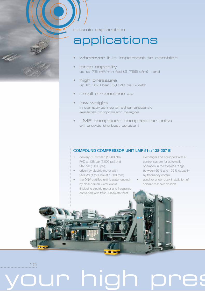
COMPOUND COMPRESSOR UNIT LMF 51s / 138-207 E
• delivery 51 m³ / min (1,800 cfm) FAD at 138 bar (2,000 psi) and 207 bar (3,000 psi);
• driven by electric motor with 950 kW (1,274 hp) at 1,500 rpm;
• the DNV-certified unit is water-cooled by closed fresh water circuit (including electric motor and frequency converter) with fresh- / seawater heat
exchanger and equipped with a control system for automatic operation in the stepless range between 50 % and 100 % capacity by frequency control;
• used for under-deck installation of seismic research vessels
• wherever it is important to combine
• large capacity up to 78 m3 / min fad (2,755 cfm) – and
• high pressure up to 350 bar (5,076 psi) – with
• small dimensions and
• low weight in comparison to all other presently available compressor designs
• LMF compound compressor units will provide the best solution!

your high pressure solution
www.lmf.at
11
seismic exploration
applicationsCOMPOUND COMPRESSOR UNIT LMF 21s / 138-207 D
• containerized (24.6 ft container), including HP-air receiver and HP-control valve;
• delivery 21 m³ / min (742 cfm) FAD at 138 bar (2,000 psi) and 207 bar (3,000 psi);
• driven by 12-cylinder diesel engine with 448 kW (600 hp) at 1,600 rpm;
• the DNV-certified unit is water-cooled
by closed fresh-water circuit with fresh- / seawater heat exchanger and equipped with a control system for automatic operation in the stepless
• range between 50 % and 100 % capacity with a reduction of fuel consumption of 40 %;
• used for on-deck installation of seismic research vessels
PORTABLE COMPOUND COMPRESSOR UNIT LMF V19 / 5621 L20.7 D
• containerized (14.7 ft container), including HP-air receiver, HP-control valve and 16-channel HP-manifold;
• delivery 5.2 m³ / min (183 cfm) FAD at 207bar (3,000 psi);
• driven by 6-cylinder water-cooled diesel engine with 152 kW (203 hp) at 2,200 rpm;
• used for on-deck installation of seismic research vessels as well as for shallow-water exploration
• wherever it is important to combine
• large capacity up to 78 m3 / min fad (2,755 cfm) – and
• high pressure up to 350 bar (5,076 psi) – with
• small dimensions and
• low weight in comparison to all other presently available compressor designs
• LMF compound compressor units will provide the best solution!
MOBILE SYSTEMS
your high pressure solution
www.lmf.at
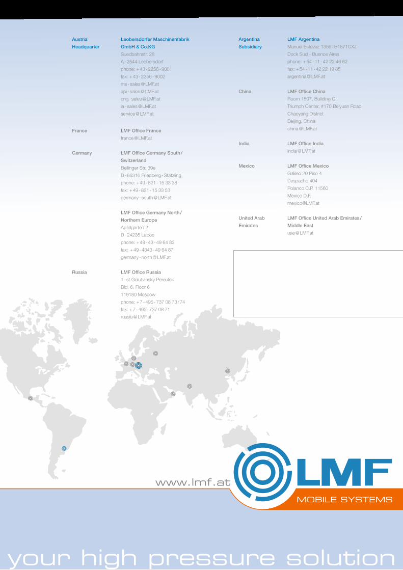
Austria Leobersdorfer Maschinenfabrik
Headquarter GmbH & Co.KG
Suedbahnstr. 28
A - 2544 Leobersdorf
phone: + 43 - 2256 - 9001
fax: + 43 - 2256 - 9002
ms - sales @ LMF.at
api - sales @ LMF.at
cng - sales @ LMF.at
ia - sales @ LMF.at
service @ LMF.at
France LMF Office France
france @ LMF.at
Germany LMF Office Germany South /
Switzerland
Beilinger Str. 39e
D - 86316 Friedberg - Stätzling
phone: + 49 - 821 - 15 33 38
fax: + 49 - 821 - 15 33 53
germany - south @ LMF.at
LMF Office Germany North /
Northern Europe
Apfelgarten 2
D - 24235 Laboe
phone: + 49 - 43 - 49 64 83
fax: + 49 - 4343 - 49 64 87
germany - north @ LMF.at
Russia LMF Office Russia
1 - st Golutvinsky Pereulok
Bld. 6, Floor 6
119180 Moscow
phone: + 7 - 495 - 737 08 73 / 74
fax: + 7 - 495 - 737 08 71
russia @ LMF.at
Argentina LMF Argentina
Subsidiary Manuel Estévez 1356 - B1871CXJ
Dock Sud - Buenos Aires
phone: + 54 - 11 - 42 22 46 62
fax: + 54 - 11 - 42 22 19 85
argentina @ LMF.at
China LMF Office China
Room 1507, Building C,
Triumph Center, #170 Beiyuan Road
Chaoyang District
Beijing, China
china @ LMF.at
India LMF Office India
india @ LMF.at
Mexico LMF Office Mexico
Galileo 20 Piso 4
Despacho 404
Polanco C.P. 11560
Mexico D.F.
United Arab LMF Office United Arab Emirates /
Emirates Middle East
uae @ LMF.at


![Rest API Documentation - Gier API... · Rest API Documentation {{}, {}],}](https://static.fdocuments.in/doc/165x107/5fdbbd98d3d6d85ee1033c5a/rest-api-documentation-gier-api-rest-api-documentation-.jpg)