Seismic protective systems for bridges and highway ... · Seismic protective systems for bridges...
16
65 Japan-Bangladesh Joint Seminar on Advances in Bridge Engineering ISBN: 984-32-2520-6 Dhaka, Bangladesh. 10 August 2005 Seismic protective systems for bridges and highway structures in Bangladesh Asif Iqbal * Bangladesh Consultants Limited House 95A, Road 4, Block F, Banani, Dhaka 1213, Bangladesh. Abstract Mechanical equipment that is used to protect the superstructure of bridges and flyovers against earthquakes are being used in increasing numbers all over the world in recent times. They have been used in a few structures in here as well in the last few years. This paper describes the application of such devices in three major structures: Jamuna Multipurpose Bridge, Paksey Bridge and Mohakhali Flyover in Dhaka city. The concepts behind the designs and applications are explained for each case. The descriptions and working principles illustrate how the systems perform according to those concepts. Test details are provided to explain how it is assured that the devices would act exactly the way they are intended to, once they are in place. 1. Introduction The concept of using additional devices for protection of civil engineering structures from seismic damage is around for a long time. In countries like Italy and New Zealand, that idea has been put to practice in many structures for more than thirty years now. But over the past two decades there had been tremendous developments in this area with new computational and testing facilities. Hundreds of new applications have been made during this time in road and rail bridges, viaducts and similar type of structures as well as buildings for both new construction and retrofitting of old structures. There have been some major developments in infrastructure in Bangladesh in the past twenty years. Major bridges have been built over rivers and road networks have been improved. As the major protects have utilized modern technologies, there had been application of seismic devices in some of these bridges as the design required. Energy dissipating elements have been used in Jamuna Multipurpose Bridge where as in Paksey Bridge and Mohakhali Flyover the structures have been fitted with systems to lock-up the superstructure with the rest during an earthquake. * E-mail: [email protected]
Transcript of Seismic protective systems for bridges and highway ... · Seismic protective systems for bridges...

65
Japan-Bangladesh Joint Seminar on Advances in Bridge Engineering ISBN: 984-32-2520-6 Dhaka, Bangladesh. 10 August 2005
Seismic protective systems for bridges and highway structures in Bangladesh
Asif Iqbal*
Bangladesh Consultants Limited
House 95A, Road 4, Block F, Banani, Dhaka 1213, Bangladesh. Abstract Mechanical equipment that is used to protect the superstructure of bridges and flyovers against earthquakes are being used in increasing numbers all over the world in recent times. They have been used in a few structures in here as well in the last few years. This paper describes the application of such devices in three major structures: Jamuna Multipurpose Bridge, Paksey Bridge and Mohakhali Flyover in Dhaka city. The concepts behind the designs and applications are explained for each case. The descriptions and working principles illustrate how the systems perform according to those concepts. Test details are provided to explain how it is assured that the devices would act exactly the way they are intended to, once they are in place.
1. Introduction The concept of using additional devices for protection of civil engineering structures from seismic damage is around for a long time. In countries like Italy and New Zealand, that idea has been put to practice in many structures for more than thirty years now. But over the past two decades there had been tremendous developments in this area with new computational and testing facilities. Hundreds of new applications have been made during this time in road and rail bridges, viaducts and similar type of structures as well as buildings for both new construction and retrofitting of old structures. There have been some major developments in infrastructure in Bangladesh in the past twenty years. Major bridges have been built over rivers and road networks have been improved. As the major protects have utilized modern technologies, there had been application of seismic devices in some of these bridges as the design required. Energy dissipating elements have been used in Jamuna Multipurpose Bridge where as in Paksey Bridge and Mohakhali Flyover the structures have been fitted with systems to lock-up the superstructure with the rest during an earthquake.
* E-mail: [email protected]

66
Fig. 1. Jamuna Multipurpose Bridge 2. Jamuna Multipurpose Bridge The 4.8-km long Jamuna Multipurpose Bridge (Figure 1) is the longest bridge in Bangladesh spanning across the mighty Jamuna River. Carrying road and rail tracks, a gas pipeline and a power transmission line, the structure is of enormous economic and strategic importance. A site-specific seismicity study concluded that earthquakes of Richter magnitude upto 7.0 may occur at the bridge location originating from the adjacent Bogra fault zone, which lies some 25 to 50 km to the northwest. The study provided a design spectrum with a peak-acceleration close to the surface of 0.2 g and a peak structural response of 0.47g. It is also estimated that the ground up to 15 m below the riverbed level may liquefy under an earthquake shaking.
Fig. 2. Span Arrangements of Jamuna Multipurpose Bridge
The bridge consists of 47 equal spans of 99.375m each plus two end-spans each 68.375m long. The main bridge superstructure is prestressed concrete box-girders and the substructure includes 3-pile and 2-pile piers. The bridge is divided into seven modules

67
(two end modules, four 7-span modules and a 6-span module in the middle), which means there are six expansion joints between the two ends (Figure 2). The foundations consist of driven tubular steel piles, filled with concrete. Pile caps are of pre-cast reinforced concrete shell with in-situ reinforced concrete in-fill construction. The pile caps carry pier stems, which in turn support the bearings. The height of pier stem varies from 2.72m to 12.05m and is constructed of reinforced concrete. The deck is of prestressed post-tensioned concrete segmental construction, with a varying depth single box section. The intention behind the seismic design of the bridge was to provide ductility to the structure. (RPT-NEDEC-BCL 1990). This way the piers and piles will not be excessively large as would be required to remain elastic during the design earthquake. But the deformations achieved because of the ductility should occur in such areas where they can be accessed and repaired. Providing metal restrainers between the deck and the top of the pier was a practical idea. The restrainer would yield to absorb energy and isolate the deck from the piers through allowing relative movements. The threshold force is also predefined from the restrainer size and material properties.
Fig. 3. Schematic drawing of seismic restrainer A very simple type of device that had been investigated and used in real structures in New Zealand (Tyler 1978, Park and Blakeley 1978) was conceived at the preliminary stage (Figure 3). That concept was eventually applied in the bridge with some modified shape of the device. In concept, the seismic restrainer is not much more than a mild steel bar placed vertically between the soffit of the deck and the top of the pier (Figure 3). The material is ductile and the shape is as such that the ratio of the applied bending moment to the plastic moment of resistance is normally constant over the lower third of the free height. The bar exhibits plastic deformation under stresses beyond the threshold force and the plasticity is confined to the free height because of the shape. Shear stresses in the bar are kept low intentionally by the proportions. The bar is also free to slide vertically during the elastoplastic movement so that any geometric non-linearity and subsequent instability cannot occur in the arrangement.

68
Figure 4 shows typical load-deflection curve of a hysteretic device. The values of the force and displacement are arbitrary and so are the numbers of cycles. It just qualitatively indicates the behaviour of the device. The area inside the curve gives the amount of energy absorbed.
Fig. 4. Typical load-deflection curve of a steel hysteretic device
Bottom end of the device is always connected to the top of the pier. The arrangement of the connections of the top end of the devices with the superstructure depends on the location of the pier within the structure. In each module of the bridge there is a central pier, which is either the one at the centre of the module or one of the piers closest to the centre. In this pier top end of the device is connected directly to the superstructure.
In other piers of the module the connection between the top of the bar and the soffit of the deck utilizes another device called Shock Transmission Unit (STU). Practically it is nothing but a cylinder filled with viscous non-compressible fluid and a piston within. The piston is connected with a piston rod that extends out of the cylinder. The fluid inside the cylinder can slowly squeeze past the cylinder when the piston moves within the cylinder. This can happen when the piston rod is either pushed back or pulled out of the cylinder. If the movements are very slow the resistance is small but if there is any sudden movement of the piston rod the piston inside will be “locked” into position because of the viscosity of the fluid. This is why STUs are also known as Lock-Up Devices. Figure 5 shows arrangement of seismic devices in a seven-span module at both service and seismic conditions.
Fig. 5. Working principle of STU

69
At the piers other than the central pier there would be a very slow relative movement between the superstructure and the pier because of thermal changes, creep, shrinkage etc. But in the event of an earthquake there would be tendency of instantaneous relative displacement between the two. At these locations it is necessary to keep the provisions for the very slow movements but the seismic movements must be arrested. This is achieved with the STUs. The top of the seismic device is connected with deck through a STU. There will be very little force on the seismic device during the slow movements but the horizontal force will be transferred to it when the STU locks up during an earthquake.
Fig. 6. Arrangement of seismic devices in a module
When the details for the actual device were worked out the single pin element was replaced by a group of 42 equal-sized pins spread across the length and the width of the device (Figure 7). The multiple-pin arrangement provided necessary redundancy as well as possible provision of maintenance and replacement.

70
Two types of dissipating device are used depending on the mechanism of operation. The centre of portion each module has the fixed-type, i.e., in these locations (at the 3-pile piers), there are multipin elastoplastic devices in which all horizontal movements other than those occurring in very short durations are accommodated by the elastic deformation of the pin elements. At the 2-pile piers, mobile-type devices are used that include shock transmitters with the multipin elements to allow slowly occurring movements (like the thermal expansions and contractions of the bridge superstructure) through adjustments by the shock transmitters. At sudden onset of loads, such as during an earthquake, the horizontal forces are resisted by pin elements in both the fixed and mobile-type devices. The sharing of the loads is achieved because the shock transmitter in the mobile locations locks up and transmits the loads to the pin elements. Fig. 3 shows the section of the device, which comprises of the following major components (FIP Industriale, 1996a):
A central body with pin dissipating elements An upper and a lower plate, between which the pins are affixed A frame with two tapered faces is affixed to the superstructure. Two frames, one
on either side of the central body, with an outer surfaces tapered to match the taper of the inner frame is attached to the top of the pier maintaining the required clearances for the deformation of the pins. The inner and outer frames together form a fail-safe mechanism.
The dissipating device for the mobile locations includes a shock transmission unit made of a one-piece hydraulic cylinder that has both the end closed and a double-headed piston rod that creates two chambers within the cylinder.
Fig. 7. Details of the energy-dissipating device: (1) pin dissipating element; (2) shock transmission
unit; (3) stop-block element The pins and the STUs are designed for a seismic load capacity of 4200 kN and displacement range of ±200 mm. The clear distance between the faces of the stop block element is 250 mm.

71
Fig. 8. View of a complete seismic device used in Jamuna Bridge
A very important step in application of any special device is testing. Since the devices vary widely in respect of material, arrangement and working principle, device-specific testing scheme and verification procedure have to be formulated. The devices used in real structures are usually very big and it is not always possible to test the prototypes. Scaled models or smaller arrangements are used in most cases and they are believed to be representative of the full-sized devices. In case of devices for the Jamuna bridge, a 4-pin setup was tested in place of the whole device with 42 pins (FIP Industriale, 1996b). The STUs tested, however, were full-sized and with full movement capacity.
Fig. 9. Test of a steel hysteretic device
Rigorous testing protocol had been implemented for the pins and the STUs. The group of pins was tested first for 15 cycles of design displacement of 200mm each way. Then the displacement was continued until rupture of one pin at 315 mm. The tests revealed that the elastic displacement of the pins is 27mm and rest of the design displacement is plastic displacement. For the whole device the elastic force and plastic force were calculated to be 3333.75 kN and 4173.75 kN respectively. So the increase in force in the device is much less compared to the displacement after the elastic limit. That means the force transferred to the piers would be much less that it would have been if the mechanism had remained elastic.

72
STUs were tested through a protocol similar to that of the pins. Three sets of tests were done at 27C, 10C and 40C and like the tests of the pins, each set comprised of low velocity test, high velocity test and dynamic test. The low velocity test verifies the slow movement capacity of the device as would be required for thermal change and shrinkage. The high velocity test examines the lock-up capability at sudden movements. The device is tested with sinusoidal movements in the dynamic test to verify if the lock-up mechanism holds throughout a seismic event. In the low velocity tests the piston is moved at a rate of around 0.03 mm/sec for a stroke of 20mm for each side and 1.5 cycle in total for a total movement of 120mm. The Reaction force was measured to be 45 kN at 27C, 70 kN at 10C and 25 kN at 40C and against a maximum load of 4175 kN (2.16%, 3.35% and 1.20% respectively). The small amount of reaction force means that there will be almost insignificant amount of load exerted on the substructure during the very slow thermal or other types of movements. The other point that should be noticed here is that with the increase of temperature the silicon compound inside the cylinder becomes more fluid allowing a lower reaction for slow movement.
Fig. 10. (a) Load-deflection plot of 4-pin arrangement (b) nominal curve of a complete hysteretic
device indicating accepted value For the high velocity test a constant force of 22600 kN and a constant velocity of 26 mm/sec were maintained in the all the tests at three different temperatures. Displacements of the piston were 16.64 mm at 27C, 6 mm at 10C and 24 mm at 40C. The tests demonstrated that the silicon compound of STU is capable of achieving the

73
maximum reaction under impulsive shocks but with slightly increasing displacements at greater temperatures. The dynamic test was carried out with a force of around 2000 kN in sinusoidal way and a frequency of 0.4 Hz to 0.5 Hz at 27C, 10C and 40C. Pressure and displacements were measured at the 1st, 10th and 20th cycles. That was used to calculate the ratios between the actual displacements and the stroke allowed by the STUs. At 27C the ratio came up as 4.78% from the 1st cycle, 4.72% from the 10th cycle and 5.76% from the 20th cycle. At 10C they were 5.22%, 5.87% and 6.52% respectively while it was 5.22% at the 1st cycle at 40C. It should be noted here that the displacement increases as the test progresses. This is because with the movement of the piston within the cylinder the temperature of the fluid increases reducing its own stiffness and allowing for a greater displacement. But still the STUs generally exhibit enough resistance under sustained dynamic loads. This type of devices has been widely used in many bridges in Italy and in some other countries for more than 30 years now. The inherent concept brings in some advantages as well as possibilities of some situations that may have practical difficulties (Tsopelas and Constantinou 1994, 1997, Iqbal 2002). The material behaviour of mild steel (Figure 10) shows that the pins remain elastic upto the elastic limit. There would be little increase of force once the yield point is crossed, but in exchange of large strains. So the maximum force transmitted to the substructure through the device can be predicted. That gives a huge advantage in designing the piers and abutments irrespective of the nature of the ground motion. It is evident from analysis of the concept that the system is effective in reducing deck acceleration and transmission of forces to the substructure. But beyond the elastic limit the system exhibits significant permanent displacements due to lack of restoring forces within the device. Once the elastic limit of the mild steel is exceeded, the whole structure needs to be realigned externally. This is likely to be the case after a major earthquake. But there can be significant aftershocks shortly after the main event, which can add to the permanent deformations before any such work is done. Besides, some pins can fail during a major earthquake and they need to be replaced to take the device to its original stiffness level. Until that is done, the system remains at a degraded stiffness level, which can also be potentially dangerous in case there is any subsequent major earthquake. One other concern is that the peak bearing displacement during an earthquake can exceed the design displacement. That can lead to additional forces on the superstructure due to pounding action, which means the main advantage of ‘predicted’ seismic forces on the pier can be rendered invalid. Interestingly, the design philosophy of the Jamuna Bridge can be considered compatible with the next generation of codes emerging on the basis of performance-based design concept rather than conventional force-based approach (Iqbal and Al-Hussaini, 2002). A two-level design approach is suggested for performance-based seismic design in accordance with the types of ground motion considered. A ‘functional-evaluation ground motion’ is a moderate earthquake that has a reasonable probability of occurrence during the lifetime of the structure. The structure should be able to resist the forces produced

74
from this earthquake without significant damage to the basic system. A ‘safety-evaluation ground motion’ is the strongest possible earthquake that could ever be expected to occur at the site. Considering the low probability of that occurring it is economically justified to allow structural damage due to this type of ground motion; however, total collapse and serious damage of life and property cannot be considered acceptable. The operational principles of elastoplastic devices are inherently organised to fit into the performance-based design approach. Forces generated by ordinary conditions like wind, braking, centrifugal actions and even minor earthquakes are resisted elastically by the steel dampers without any distress. During the design earthquake the device may exhibit elastoplastic behaviour with some permanent deformations. If necessary, the bridge superstructure will be re-centred externally and with replacement of any damaged element of the energy-dissipating device. In case of the maximum credible earthquake the steel dampers will absorb energy as much energy through yielding. If the design displacements are exceeded, there is a fail-safe mechanism in place to prevent structural collapse. Sufficient support lengths and continuity of deck should prevent total collapse.
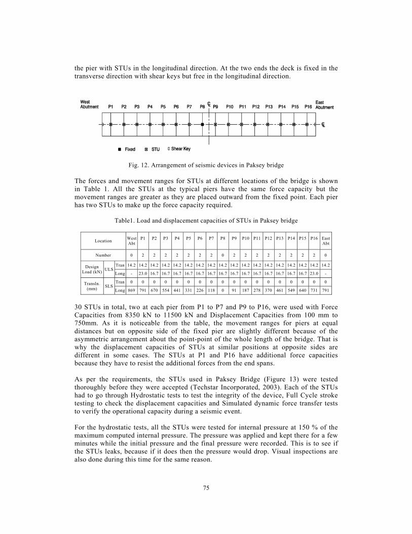
Fig. 11. Paksey bridge 3. Paksey Bridge The 1786m long Paksey Bridge (Figure 11) comprises of 15 typical spans of around 109.5 meters and end spans of 71.75 meters. The superstructure is of concrete box girder deck and piers are also of concrete supported by steel piles. The whole structure is one single module with continuous deck between the abutments (MM-RPT-JOC-BCL 1996). This bridge is intended to act like an integral structure during an earthquake. That means the superstructure would be locked to the substructure at all piers. But there must be provisions for movements of the deck due to temperature changes, creep and shrinkage. This performance objective is achieved by STUs. The deck is connected to the piers at all locations except one around the centre (Figure 12). Ideally, the centre of the deck would be restrained in both directions to the pier. Since in this case the number of spans is not even, the fixed point is at one of the two nearest piers. At all of the other piers the deck is transversely restrained and connected to
75
the pier with STUs in the longitudinal direction. At the two ends the deck is fixed in the transverse direction with shear keys but free in the longitudinal direction.
Fig. 12. Arrangement of seismic devices in Paksey bridge
The forces and movement ranges for STUs at different locations of the bridge is shown in Table 1. All the STUs at the typical piers have the same force capacity but the movement ranges are greater as they are placed outward from the fixed point. Each pier has two STUs to make up the force capacity required.
Table1. Load and displacement capacities of STUs in Paksey bridge
Location West Abt
P1
P2
P3
P4
P5
P6
P7
P8
P9
P10
P11
P12
P13
P14
P15
P16
East Abt
Number 0 2 2 2 2 2 2 2 0 2 2 2 2 2 2 2 2 0
Design Load (kN)
ULS Tran 14.2 14.2 14.2 14.2 14.2 14.2 14.2 14.2 14.2 14.2 14.2 14.2 14.2 14.2 14.2 14.2 14.2 14.2
Long - 23.0 16.7 16.7 16.7 16.7 16.7 16.7 16.7 16.7 16.7 16.7 16.7 16.7 16.7 16.7 23.0 -
Transln. (mm)
SLS Tran 0 0 0 0 0 0 0 0 0 0 0 0 0 0 0 0 0 0
Long 869 791 670 554 441 331 226 118 0 91 187 278 370 461 549 640 731 791
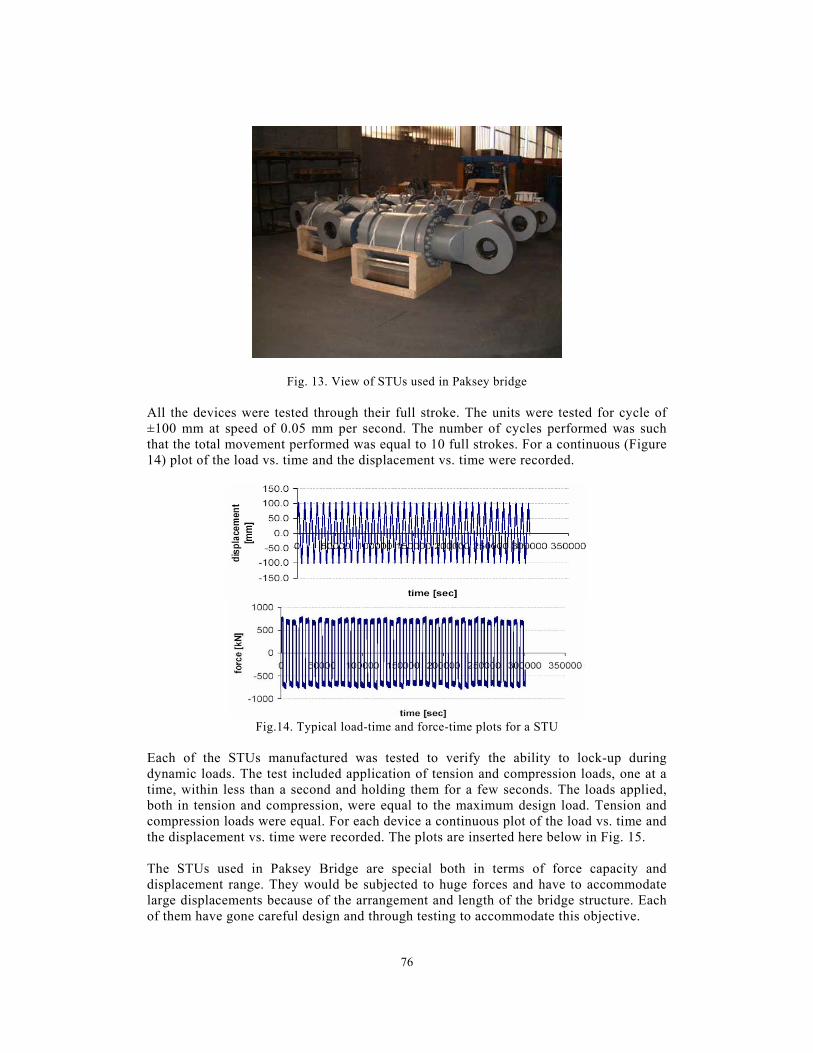
30 STUs in total, two at each pier from P1 to P7 and P9 to P16, were used with Force Capacities from 8350 kN to 11500 kN and Displacement Capacities from 100 mm to 750mm. As it is noticeable from the table, the movement ranges for piers at equal distances but on opposite side of the fixed pier are slightly different because of the asymmetric arrangement about the point-point of the whole length of the bridge. That is why the displacement capacities of STUs at similar positions at opposite sides are different in some cases. The STUs at P1 and P16 have additional force capacities because they have to resist the additional forces from the end spans. As per the requirements, the STUs used in Paksey Bridge (Figure 13) were tested thoroughly before they were accepted (Techstar Incorporated, 2003). Each of the STUs had to go through Hydrostatic tests to test the integrity of the device, Full Cycle stroke testing to check the displacement capacities and Simulated dynamic force transfer tests to verify the operational capacity during a seismic event. For the hydrostatic tests, all the STUs were tested for internal pressure at 150 % of the maximum computed internal pressure. The pressure was applied and kept there for a few minutes while the initial pressure and the final pressure were recorded. This is to see if the STUs leaks, because if it does then the pressure would drop. Visual inspections are also done during this time for the same reason.
76
Fig. 13. View of STUs used in Paksey bridge All the devices were tested through their full stroke. The units were tested for cycle of ±100 mm at speed of 0.05 mm per second. The number of cycles performed was such that the total movement performed was equal to 10 full strokes. For a continuous (Figure 14) plot of the load vs. time and the displacement vs. time were recorded.
Fig.14. Typical load-time and force-time plots for a STU
Each of the STUs manufactured was tested to verify the ability to lock-up during dynamic loads. The test included application of tension and compression loads, one at a time, within less than a second and holding them for a few seconds. The loads applied, both in tension and compression, were equal to the maximum design load. Tension and compression loads were equal. For each device a continuous plot of the load vs. time and the displacement vs. time were recorded. The plots are inserted here below in Fig. 15. The STUs used in Paksey Bridge are special both in terms of force capacity and displacement range. They would be subjected to huge forces and have to accommodate large displacements because of the arrangement and length of the bridge structure. Each of them have gone careful design and through testing to accommodate this objective.

77
Fig. 15. Displacement-time and load-time plots for a STU
4. Mohakhali flyover Mohakhali Flyover (Figure 16) is the first of its kind to be built in the country. This was planned as part of Dhaka Urban Transport Project to help remove traffic congestion at Mohakhali rail-crossing area of the city. The flyover is little over a kilometre long in total while the length of the structure is 687 meters. The whole structure is of concrete with the four-lane box girder deck. The structure has 19 spans in total, but they are divided into three structural modules (Figure 17). The each of the two modules at the ends are made of pre-cast segments and have the typical span length is 38 meter with around 27 meter long end spans at both ends. The module in the middle is cast in situ and has a long span of 63 meter over the railroad. The other spans in this module range from around 31 to 35 meters (DSM Consultants 2002).
Fig. 16. Mohakhali flyover The structural arrangements of the modules determine their seismic behaviour. In each module the concrete decks are continuous from one to another. The deck is fixed with a pier near the middle of each span. There are STUs between the deck and the pier at other locations in an arrangement similar to that of Figure 18. The two ends of the structure are also connected to the abutments. During an earthquake all the STUs provide restrains in the longitudinal direction. The connections are in such a way that they are fixed in the

78
transverse direction all the time. So the deck would be restrained at all support locations in case of a seismic event.
Fig. 17. Arrangement of seismic devices in Mohakhali flyover
Because of the curvature in the alignment, the orientations of the STUs are also significant. In each of the module the shear keys that produce the restrains in the typical piers are aligned towards the fixed restraint of that module.
Fig. 18. STU between the substructure and the deck
Table 2 shows the design forces and the movements at each pier location. Examining them for the proposed arrangement reveals that because more STUs are used in the module they need to be of smaller capacity in terms of both forces and movements. The two end modules have larger forces and relatively greater movement ranges. Like most cases of this type of applications, the contractors were asked to design and work out the details of the STUs. The STUs had to be designed to operate in the temperature range of 0C to 60C and a relative humidity of 100 percent in addition to the movements caused by traffic and wind excitation. The device is designed to withstand the force in lateral or vertical direction generated by twice its own weight in

79
addition to the design axial load. There should be a minimum factor of safety of 1.3 for the material yield strength and 1.4 for material ultimate tensile strength. The operational requirements are such that the device is designed for a wind loading of 1750 kN for 100,000 cycles per year and 20 cycles of seismic loading once every 10 years. The functional life of the STUs would be 40 years but they may be maintained and repaired within this period. It should be also relatively easy to remove and replace them if that becomes necessary. But it is imperative that refurbishment would not be required before at least one maximum credible earthquake.
Table 2. Load and displacement capacities of STUs in Mohakhali flyover
Location N.
Abt
P1 P2 P3 P4 P5 P6 P7 P8 P9 P10 P11 P12 P13 P14 P15 P16 P17 P18 W. Abt Pre. Situ Situ Pre.
Number 1 2 2 2 2 0 2 2 2 1 4 4 0 4 4 1 2 2 0 2 2 1
Design Load (kN)
ULS
Tran 2.39 8.89 8.89 8.89 8.89 8.89 8.89 8.89 8.89 2.39 8.89 8.89 10.8 10.8 8.89 2.39 8.89 8.89 8.89 8.89 8.89 2.39
Long 2.39 7.82 7.82 7.82 7.82 7.82 7.82 7.82 7.82 2.39 7.82 7.82 9.51 9.51 7.82 2.39 7.82 7.82 7.82 7.82 7.82 2.39
Transln. (mm)
SLS
Tran 0 0 0 0 0 0 0 0 0 0 0 0 0 0 0 0 0 0 0 0 0 0
Long 48 38 29 20 10 0 10 20 29 38 18 9 0 18 29 29 20 10 0 10 20 29
42 STUs have been proposed in total for the whole structure. The requirements in terms of force and displacement capacities are comparable. So multiple numbers of devices with the same capacity can be used at different locations. Like the piers of the module in the middle have larger forces and four STUs are used in these locations where two are used at typical piers of other modules. Again, force capacity requirements at both ends of the modules are less and that is why only one STU is attached at these locations. The STUs had to go through a detailed testing scheme for this structure also. A testing scheme similar to that for the STUs used in Paksey Bridge had been accepted. Hydrostatic Testing was done by 150% of maximum computed internal pressure kept for three minutes to verify the structural integrity of the high-pressure boundary. Full Cycle Stroke Testing means testing the STUs for ten complete cycles of movement at a velocity between 0.02 mm to 0.05 mm per second. During the Full Force-Velocity Performance Testing the STUs shall have the full design force applied by piston moving at a maximum speed of 0.5 mm per second. They would be tested in both compression and tension but testing need not be cyclic. This is to see if the device can stand the pressure at this load. The deflection at which a constant stiffness is achieved is taken as lock-up deflection and corresponding force is termed lock-up force. The acceptance criteria require that the deflection from the point of lock up to the maximum test load must be less than 25 mm. Simulated Dynamic Force Transfer Test would verify the ability of the devices to lock up during dynamic loads. The STUs would be put through both tension and compression; one at a time, within 0.5 second and the load would be sustained for 5 seconds. The force would be at least three times the lock-up force determined in the Full Force-Velocity Performance Testing but not more than the design force. Deflections during the application or reversal of forces should not exceed 25 mm. Also, the deflections due to sustained loads should not exceed 25 mm. The installation of the STUs in Mohakhali Flyover is still continued during the time of preparation of this paper.

80
5. Conclusion The conceptual and design issues of application of two different types of seismic devices in three structures are presented here. It is clear that these devices are part of the whole mechanism of giving the structures protection against earthquakes. These are the first examples of such applications in this country. As the technology progresses with time people will have more confidence in them as effective in serving that purpose and more of them are likely to be used in similar structures in the near future. Reference Bolt, B. A. (1987), Site Specific Study of Seismic Intensity and Ground Motion Parameters for
Proposed Jamuna River Bridge, Bangladesh, Report presented to Jamuna Multipurpose Bridge Authority.
DSM Consultants (2002), Mohakhali Flyover Design Report. FIP Industriale (1996a), Technical Report on Elastoplastic Device for Seismic Protection of
Jamuna Multipurpose Bridge, Padova, Italy. FIP Industriale (1996b), Test Report on Bearings and Seismic Devices for Jamuna Multipurpose
Bridge, Padova, Italy. Iqbal, A. (2002) “Study of Seismic Isolation System of Jamuna Multipurpose Bridge,
Bangladesh”, Proceedings of the 15th Engineering Mechanics Conference of the American Society of Civil Engineers, New York, USA.
Iqbal, A. and Al-Hussaini, T. M. (2002), “Elastoplastic Isolation System for Performance-Based Seismic Design of Bridges”, Proceedings of ATC 17-2 Seminar on Response Modification Technologies for Performance-Based Seismic Design, Los Angeles, USA.
MM-RPT-JOC-BCL (1996), Paksey Bridge Design Report. Park, R. G. and Blakeley, R. W. G. (1978), “Seismic Design of Bridges”, Road Research Unit,
National Roads Board, Bridge Seminar, New Zealand. RPT-NEDECO-BCL (1990), Jamuna Bridge Project Phase II Study Design Report. Techstar Incorporated (2003), Paksey Bridge Shock Transmission Devices Algasism Test Report,
Ohio, USA. Tyler, R. G. (1978). “Tapered Steel Energy Dissipaters for Earthquake Resistant Structures”,
Bulletin of the New Zealand National Society for Earthquake Engineering, Vol 11, No. 4. Tsopelas, P. and Constantinou, M.C. (1994). NCEER-TAISEI Corporation Research Program on
Sliding Seismic Isolation Systems for Bridges-Experimental and Analytical Study of a System Consisting of Lubricated PTFE Sliding Bearings and Mild Steel Dampers, Rep. No. NCEER 94-0014, National Center for Earthquake Engineering Research, State University of New York at Buffalo, New York, USA.
Tsopelas, P. and Constantinou, M.C. (1994). “Study of Elastoplastic Bridge Seismic Isolation System”, ASCE Journal of Structural Engineering, 123(4), 489-498.


![53] Seismic behavior of chilean bridges with seismic ... · 53] 5 Martine Dia, M ere, I Revista de la onstruccin ournal of onstruction Seismic behavior of chilean bridges with seismic](https://static.fdocuments.in/doc/165x107/5bdf096309d3f244198bab65/53-seismic-behavior-of-chilean-bridges-with-seismic-53-5-martine-dia.jpg)