SEISMIC POUNDING OF MULTISTOREYED...
6
IJRET: International Journal of Research in Engineering and Technology eISSN: 2319-1163 | pISSN: 2321-7308 __________________________________________________________________________________________ IC-RICE Conference Issue | Nov-2013, Available @ http://www.ijret.org 12 SEISMIC POUNDING OF MULTISTOREYED BUILDINGS Khaja Afroz Jamal 1 , H.S.Vidyadhara 2 1 Post Graduate Student, 2 Associate Professor, Department of Civil Engineering, Poojya Doddappa Appa College of Engineering, Gulbarga 585-104, India [email protected], [email protected] Abstract The investigations made by past and present earthquake seismologist have shown that during earthquake, the building structures are vulnerable to severe damages. The adjacent buildings collide and collapse during moderate to strong ground vibrations caused by earthquakes. Actually, the separation distance of many buildings is n adequate to accommodate their relative motions, so building vibrate out of phase and collapse. Among the possible structural damages the seismic induced pounding has been commonly observed phenomenon. In this paper, a systematic study regarding pounding of building response as well as seismic hazard mitigation practices like effect of different separation distances and effect of addition of shear walls are investigated in ETABS nonlinear software. The results were obtained in the form of pounding force and point displacements. As the pounding effect varies inversely with separation distance so by increasing separation distance pounding effect is reduced greatly and hence damage to neighboring buildings is minimized. Also, the provision of shear wall reduces effect of pounding. Key words: Seismic Pounding, Separation Distance, Mitigation of Seismic Pounding, Adjacent Buildings, Gap Element, Impact, Shear wall. ---------------------------------------------------------------------***--------------------------------------------------------------------- 1. INTRODUCTION A quake with a magnitude of six is capable of causing severe damage. Several destructive earthquakes have hit India in both historical and recent times. The annual energy release in India and its vicinity is equivalent to an earthquake with magnitude varying from 5.5 to 7.3 [1]. When two structures are close together, it is expected that they will pound against each other. This situation can be easily seen in highly populated cities. Many studies were made about structural pounding considering single degree of freedom. Pounding is a highly nonlinear phenomenon and a severe load condition that could result in high magnitude and short duration floor acceleration pulses in the form of short duration spikes, which in turn cause greater damage to building contents. [1]. Pounding is critical on the responses of the stiff system, especially when the system is highly out-of-phase. Essentially, in-phase systems exhibit displacement amplifications that are much closer to one, independent of model type [2]. The pounding effect can be reduced in two ways: 1) By placing elastic materials between adjacent buildings or by reinforcing structural systems with cast-in-place reinforced concrete (RC) walls [3]. 2) By providing a safe separation distance between adjacent [4]. 1.1 Required Seismic Separation Distance to Avoid Pounding Bureau of Indian Standards clearly gives in its code IS 4326 that a Separation distance is to be provided between buildings to avoid collision during an earthquake. The code is mentions in following Table 1[5]. Table 1: Seismic pounding gap for different structures Sl. No. Type of Constructions Gap Width/Storey, in mm for Design Seismic Coefficient αh =0.1 1 Box system or frames with shear walls 15.0 2 Moment resistant reinforced concrete frame 20.0 3 Moment resistant steel frame 30.0 IS1893:2007 Part1 mentioned that, separation should be R times the sum of displacements. R may be replaced by R/2 when two buildings are at same levels, where R is response reduction factor (Clause 7.11.1) [6]. As per FEMA: 273-1997: Separation distance between adjacent structures shall be less than 4% of the building height and above to avoid pounding, also the equations for calculating gap are
Transcript of SEISMIC POUNDING OF MULTISTOREYED...

IJRET: International Journal of Research in Engineering and Technology eISSN: 2319-1163 | pISSN: 2321-7308
__________________________________________________________________________________________
IC-RICE Conference Issue | Nov-2013, Available @ http://www.ijret.org 12
SEISMIC POUNDING OF MULTISTOREYED BUILDINGS
Khaja Afroz Jamal1, H.S.Vidyadhara2 1Post Graduate Student, 2Associate Professor, Department of Civil Engineering, Poojya Doddappa Appa
College of Engineering, Gulbarga 585-104, India [email protected], [email protected]
Abstract
The investigations made by past and present earthquake seismologist have shown that during earthquake, the building structures are vulnerable to severe damages. The adjacent buildings collide and collapse during moderate to strong ground vibrations caused by earthquakes. Actually, the separation distance of many buildings is n adequate to accommodate their relative motions, so building vibrate out of phase and collapse. Among the possible structural damages the seismic induced pounding has been commonly observed phenomenon. In this paper, a systematic study regarding pounding of building response as well as seismic hazard mitigation practices like effect of different separation distances and effect of addition of shear walls are investigated in ETABS nonlinear software. The results were obtained in the form of pounding force and point displacements. As the pounding effect varies inversely with separation distance so by increasing separation distance pounding effect is reduced greatly and hence damage to neighboring buildings is minimized. Also, the provision of shear wall reduces effect of pounding. Key words: Seismic Pounding, Separation Distance, Mitigation of Seismic Pounding, Adjacent Buildings, Gap Element,
Impact, Shear wall.
---------------------------------------------------------------------***------------------------------ ---------------------------------------
1. INTRODUCTION
A quake with a magnitude of six is capable of causing severe damage. Several destructive earthquakes have hit India in both historical and recent times. The annual energy release in India and its vicinity is equivalent to an earthquake with magnitude varying from 5.5 to 7.3 [1]. When two structures are close together, it is expected that they will pound against each other. This situation can be easily seen in highly populated cities. Many studies were made about structural pounding considering single degree of freedom. Pounding is a highly nonlinear phenomenon and a severe load condition that could result in high magnitude and short duration floor acceleration pulses in the form of short duration spikes, which in turn cause greater damage to building contents. [1]. Pounding is critical on the responses of the stiff system, especially when the system is highly out-of-phase. Essentially, in-phase systems exhibit displacement amplifications that are much closer to one, independent of model type [2]. The pounding effect can be reduced in two ways:
1) By placing elastic materials between adjacent buildings or by reinforcing structural systems with cast-in-place reinforced concrete (RC) walls [3].
2) By providing a safe separation distance between adjacent [4].
1.1 Required Seismic Separation Distance to Avoid
Pounding
Bureau of Indian Standards clearly gives in its code IS 4326 that a Separation distance is to be provided between buildings to avoid collision during an earthquake. The code is mentions in following Table 1[5].
Table 1: Seismic pounding gap for different structures
Sl. No.
Type of Constructions
Gap Width/Storey, in mm for Design Seismic
Coefficient αh =0.1
1 Box system or frames
with shear walls 15.0
2 Moment resistant
reinforced concrete frame
20.0
3 Moment resistant
steel frame 30.0
IS1893:2007 Part1 mentioned that, separation should be R times the sum of displacements. R may be replaced by R/2 when two buildings are at same levels, where R is response reduction factor (Clause 7.11.1) [6]. As per FEMA: 273-1997: Separation distance between adjacent structures shall be less than 4% of the building height and above to avoid pounding, also the equations for calculating gap are

IJRET: International Journal of Research in Engineering and Technology
__________________________________________________________________________________________
IC-RICE Conference Issue | Nov-2013, Available @
S = Ua + Ub(ABS)
� � ���� � ��� (SRSS)
Where S = separation distance and Ua, Ub= peak displacement response of adjacent structures A and B, respectively [4This method is most popular so in this study this method is adopted as other methods gives somewhat conservative values. 2. METHODOLOGY
This study is carried out by analyzing reinforced concrete frames using linear static analysis, response spectrum analysis and nonlinear time history analysis in ETABS nonlinear software. Seismic and pounding responses of two multistructures are studied in aspects of displacement and pounding force. Type of pounding being analyzed is the pounding effect where shorter building collides to adjacent taller building. Besides, effect of variation of gap and addition of shear wall also studied. For linear methods the building in earthquake zone V is considered and for Time History function, ground excitation data of El Centro earthquake is chosen. 2.1 Gap Elements in Building Construction
Gap has been defined as link elements in ETABS. It is a compression-only element required to assess the force of pounding and simulate the effect of pounding. The purpose of the gap element is to transmit the force through link only when
Fig.1 Plan and elevations of the building model (Control Model)
IJRET: International Journal of Research in Engineering and Technology eISSN: 2319
__________________________________________________________________________________________
2013, Available @ http://www.ijret.org
(1)
(2)
= peak displacement adjacent structures A and B, respectively [4, 7, 8].
This method is most popular so in this study this method is adopted as other methods gives somewhat conservative
reinforced concrete using linear static analysis, response spectrum analysis
in ETABS nonlinear . Seismic and pounding responses of two multi-storey
structures are studied in aspects of displacement and pounding is the pounding effect
where shorter building collides to adjacent taller building. Besides, effect of variation of gap and addition of shear wall also studied. For linear methods the building in earthquake
ime History function, ground excitation data of El Centro earthquake is chosen.
Elements in Building Construction
Gap has been defined as link elements in ETABS. It is a to assess the force of
simulate the effect of pounding. The purpose of is to transmit the force through link only when
contact occurs and the gap is closed. Thedeformation relationship is given by Eqn. (3).
f � K�d � open�ifd �0
Where K is the spring constant, d denotes the displacement, and open is the initial gap opening,positive [9]. 3. STRUCTURAL MODELING AND ANALYSIS
In order to observe pounding between adRC buildings (12 and 9storey) areare separated by clear gap of 50mm initially and areto gravity and dynamic loading. Both buildingsin ETABS. Building-1 is a 12 storey building havingbays in x and y-direction. height of each storey is 3m and foundation height is 1.5m, Columns having size (0.55x1.0) mm2and a slab of thickness having same loading, geometry and material property that of 12 storey building. Gap elements arebetween the structures at the roof level of lower building in order to simulate contact between two surfaces by generating forces when the two surfaceserves as Control Model for this study, as shown in Fig.1.
Plan and elevations of the building model (Control Model)
GAP elementsSeismic gap
eISSN: 2319-1163 | pISSN: 2321-7308
__________________________________________________________________________________________
13
contact occurs and the gap is closed. The nonlinear force-deformation relationship is given by Eqn. (3).
� open � 0otherwise
� (3)
Where K is the spring constant, d denotes the displacement, and open is the initial gap opening, which must be zero or
STRUCTURAL MODELING AND ANALYSIS
In order to observe pounding between adjacent buildings, two RC buildings (12 and 9storey) are selected. These buildings are separated by clear gap of 50mm initially and are subjected to gravity and dynamic loading. Both buildings are analyzed
1 is a 12 storey building having 4 no. of Widths of the bays are 5m each and
height of each storey is 3m and foundation height is 1.5m, Columns having size (0.55x1.0) m2, beams are (0.35x0.6)
and a slab of thickness 0.125m. Building-2 is a 9 storey me loading, geometry and material property that of
Gap elements are linked at 9 nodes between the structures at the roof level of lower building in
contact between two surfaces by generating forces when the two surfaces approach each other, this model serves as Control Model for this study, as shown in Fig.1.
Plan and elevations of the building model (Control Model)
GAP elements

IJRET: International Journal of Research in Engineering and Technology
__________________________________________________________________________________________
IC-RICE Conference Issue | Nov-2013, Available @
Fig.2 Storey displacements
Fig.2 shows the maximum displacement of 12 and 9 storey buildings by Equivalent Static Analysis (ESA) and Response Spectrum Analysis (RSA). The top displacement of 12 and 9 storeyed building are respectively 28.77mm and 18.86mm by ESA and 19.99mm and 14.75mm by RSA methods. The safe gap required by SRSS method is 34.40mm for ESA values and 34.74mm for RSA values, which is less than provided gap. Hence, gap is sufficient to accommodate lateral displacemenas per SRSS method. But when the buildings are using El-Centro time history function, as shown in Fig.3, maximum +ve and –ve displacement for 12storey building9thfloor level is (Ua) 115.37mm at 4.52s and 117.55mm at 2.98s respectively. Also maximum +ve and for9storey building is (Ub) 74.15mm at 5.98s and 75.48mm at 1.96s respectively. According to building position, for pounding observation +ve displacement of 12 storeyand –ve displacement of 9 storey building isobserved that maximum out of phase movement of both
Fig.4 (a) Model B1with shear wall SW1
IJRET: International Journal of Research in Engineering and Technology eISSN: 2319
__________________________________________________________________________________________
2013, Available @ http://www.ijret.org
Storey displacements Fig.3 Time History of El
the maximum displacement of 12 and 9 storey
buildings by Equivalent Static Analysis (ESA) and Response Spectrum Analysis (RSA). The top displacement of 12 and 9
ively 28.77mm and 18.86mm by ESA and 19.99mm and 14.75mm by RSA methods. The safe gap required by SRSS method is 34.40mm for ESA values and 34.74mm for RSA values, which is less than provided gap. Hence, gap is sufficient to accommodate lateral displacements as per SRSS method. But when the buildings are analyzed
Centro time history function, as shown in Fig.3, for 12storey building at
) 115.37mm at 4.52s and 117.55mm at maximum +ve and –ve displacement ) 74.15mm at 5.98s and 75.48mm at
1.96s respectively. According to building position, for observation +ve displacement of 12 storey building
ve displacement of 9 storey building is observed. It is out of phase movement of both
building is 57.818mm at 3.44s. SRSS method, the safe separation distance√115.37� � 74.15� = 137.14mm which is greater than provided separation. To safe guard the building frmodification in separation distance and are made as follows: Model A1: 12 and 9 storey building with 75mm separation distance without shear walls.Model A1: 12 and 9 storey buildingdistance without shear walls.Model B1: 12 and 9 storey building with 50mm gap and shear walls SW1 as shown in Fig4(a).Model B2: 12 and 9 storey building with 50mm gap and shear walls SW2 as shown in Fig4(b).
del B1with shear wall SW1 Fig.4 (b) Model B2 with shear wall SW2
eISSN: 2319-1163 | pISSN: 2321-7308
__________________________________________________________________________________________
14
Time History of El-Centro quake
at 3.44s. As per FEMA: 273-1997 and , the safe separation distance will be � �
= 137.14mm which is greater than
uard the building from pounding effect, the following modification in separation distance and providing shear wall
Model A1: 12 and 9 storey building with 75mm separation distance without shear walls. Model A1: 12 and 9 storey building with 100mm separation
without shear walls. Model B1: 12 and 9 storey building with 50mm gap and shear walls SW1 as shown in Fig4(a). Model B2: 12 and 9 storey building with 50mm gap and shear walls SW2 as shown in Fig4(b).
Model B2 with shear wall SW2
IJRET: International Journal of Research in Engineering and Technology
__________________________________________________________________________________________
IC-RICE Conference Issue | Nov-2013, Available @
(b) Model A1
(d) Model B1
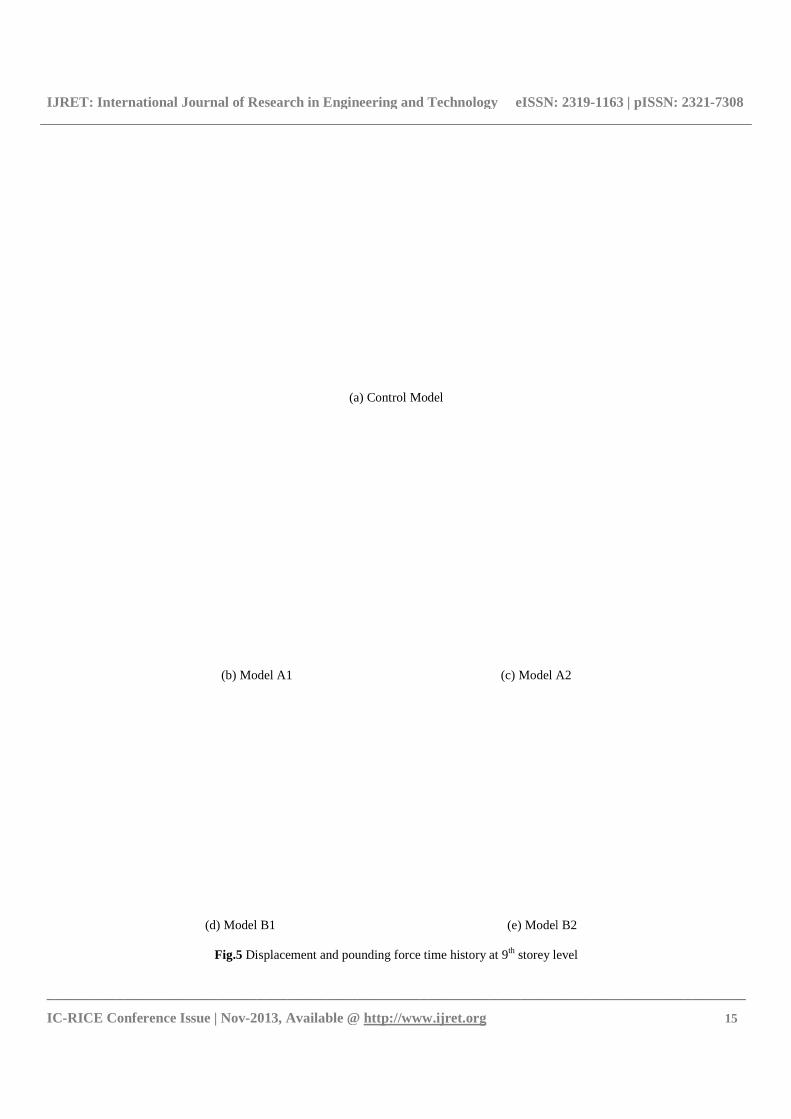
Fig.5 Displacement
IJRET: International Journal of Research in Engineering and Technology eISSN: 2319
__________________________________________________________________________________________
2013, Available @ http://www.ijret.org
(a) Control Model
(b) Model A1 (c) Model A2
(e) Model B2
Displacement and pounding force time history at 9th storey level
eISSN: 2319-1163 | pISSN: 2321-7308
__________________________________________________________________________________________
15
Model A2
) Model B2
storey level

IJRET: International Journal of Research in Engineering and Technology
__________________________________________________________________________________________
IC-RICE Conference Issue | Nov-2013, Available @
The models A1, A2, B1 and B2 are analysed under Time History Analysis (THA). Fig.5 shows that with increase in separation distance pounding force initially increase then decreases, it is said that pounding is a nonlinear phenomenon, depends on out of phase displacements of structures.figure it evident thatwhen buildings are highlypounding is maximum the out of phase displacements for models A1, A2, B1 and B2 are 85.012mm at 3
(a)
Fig.6 Storey wise pounding force with variation of (a) seismic gap & (b) with different SW
Pounding force graph for models with different separation distances shows the importance of seismic separation. As the separation distance increases the buildings are susceptible to less building damages. This holds good in case of models provided with shear walls among the two tymodeled with shear wall at outer periphery (Model B1) is more beneficial than provided inside the building (Model B2). CONCLUSIONS
As mentioned in above paragraphs, pounding effect dangerous and hazardous for buildings. The major regarding pounding effect are summarized as follows:
1) Response of building is greatly longitudinal direction because of impact forces while it is almost negligible in transverse directionis only friction force acting on transverse direction.
2) During pounding smaller building experience more displacement and liable to greater damage than larger building.
3) Usually pounding occurs when the two buildings are out of phase.
4) Pounding causes reduction in lateral displacement of building and as a result of it movements of buildings are blocked.
5) As pounding force decreases for greater separation, hence it reduces damages to the neighboring buildings.
6) Displacement of buildings can be greatly reduced by providing a shear wall, as the shear wall influences
IJRET: International Journal of Research in Engineering and Technology eISSN: 2319
__________________________________________________________________________________________
2013, Available @ http://www.ijret.org
The models A1, A2, B1 and B2 are analysed under Time shows that with increase in
separation distance pounding force initially increase then decreases, it is said that pounding is a nonlinear phenomenon, depends on out of phase displacements of structures. From figure it evident thatwhen buildings are highly out of phase pounding is maximum the out of phase displacements for
B1 and B2 are 85.012mm at 3.48s,
109.572mm at 4.5s, 60.277mm at 2.36s and 61.021mm at 5.80s respectively. By increasing gap it is evident that rate of pounding has reduced. Comparison between Models B1 and B2 shows that the buildings with SW1 have less magnitude of pounding than buildings modeled with SW2. However Fig.5 shows that, during pounding smaller building experience more displacement and liable to greater damage thbuilding.
(b)
Storey wise pounding force with variation of (a) seismic gap & (b) with different SW
models with different separation distances shows the importance of seismic separation. As the separation distance increases the buildings are susceptible to less building damages. This holds good in case of models provided with shear walls among the two types, i.e. building modeled with shear wall at outer periphery (Model B1) is more beneficial than provided inside the building (Model B2).
As mentioned in above paragraphs, pounding effect is major conclusions
regarding pounding effect are summarized as follows: Response of building is greatly affected in
of impact forces while in transverse direction as there
nsverse direction. During pounding smaller building experience more displacement and liable to greater damage than larger
Usually pounding occurs when the two buildings are
Pounding causes reduction in lateral displacement of building and as a result of it movements of buildings
force decreases for greater separation, hence it reduces damages to the neighboring
can be greatly reduced by he shear wall influences
on pounding and buildings.
REFERENCES
[1] Shehata E. Abdel Raheemadjacent building structures”, Structural Engineering
[2] S. Muthukumar and R. DesRoches, “A Hertz contact model with nonEarthquake Eng. and Structural Dynamics811-828, 2006.
[3] Mizam DOĞAN andof Adjacent RC Buildings During Seismic Loads” , Journal of Engineering and ArchitectureNo:1, 2009.
[4] A. Hameed, M. Saleem, A.U. Qazi, S. Saeed and M. A. Bashir, “Mitigation of Seismic Pounding between adjacent buildings”,64 No:4 December, 2012.
[5] IS 1893 (Part 1) : 2002Earthquake Resistant Designof StructuresGeneral Provisions and Buildings, (Fifth Revision)”.
[6] IS 4326-2005: 1993 “for Earthquake ResistantDesign and Construction of Building (Second Revision)”.
[7] FEMA-273(1997), “rehabilitation of buildings
[8] Rajaram C., Pradeep K. Ramancharla, “Study on Impact Between Adjacent Buildings: Comparison of
eISSN: 2319-1163 | pISSN: 2321-7308
__________________________________________________________________________________________
16
109.572mm at 4.5s, 60.277mm at 2.36s and 61.021mm at By increasing gap it is evident that rate of
. Comparison between Models B1 and B2 shows that the buildings with SW1 have less magnitude of pounding than buildings modeled with SW2. However Fig.5
, during pounding smaller building experience more displacement and liable to greater damage than larger
Storey wise pounding force with variation of (a) seismic gap & (b) with different SW
on pounding and reduce the effect of pounding of
Shehata E. Abdel Raheem, “Seismic pounding between adjacent building structures”, Electronic Journal of Structural Engineering, Vol. 6, pp. 66-74, 2006. S. Muthukumar and R. DesRoches, “A Hertz contact model with non-linear damping forsimulation”, Earthquake Eng. and Structural Dynamics, Vol. 35, pp.
ĞAN and Ayten GÜNAYDIN, “Pounding of Adjacent RC Buildings During Seismic Loads” , Journal of Engineering and Architecture ,Vol: XXII,
A. Hameed, M. Saleem, A.U. Qazi, S. Saeed and M. A. Bashir, “Mitigation of Seismic Pounding between adjacent buildings”,Pakistan Journal of Science, Vol. 64 No:4 December, 2012.
1) : 2002“Indian StandardCriteria for Earthquake Resistant Designof Structures, Part 1 General Provisions and Buildings, (Fifth Revision)”.
2005: 1993 “Indian Standard Code of Practice for Earthquake ResistantDesign and Construction of
cond Revision)”. “NEHRP guidelines for the seismic
rehabilitation of buildings”, Washington DC. Rajaram C., Pradeep K. Ramancharla, “Study on Impact Between Adjacent Buildings: Comparison of

IJRET: International Journal of Research in Engineering and Technology eISSN: 2319-1163 | pISSN: 2321-7308
__________________________________________________________________________________________
IC-RICE Conference Issue | Nov-2013, Available @ http://www.ijret.org 17
Codal Provisions”, 15th World Conference on Earthquake Engineering, September 2012.
[9] Raja Rizwan Hussain et.al. “Non-linear FEM Analysis of seismic induced pounding between neighbouring Multi-storey Structures”, Latin American Journal of Solids and Structures, pp.921-939 Oct 2013.
[10] Alireza M.Goltabar,R. Shamstabar kami,A. Ebadi,“Analyzing the Effective Parameters In Pounding Phenomenon Between Adjacent Structure Due To Earthquake”, The 14 th World Conference on Earthquake Engineering October 12-17, 2008, Beijing, China.
[11] Jeng-Hsiang Lin, Cheng-Chiang Weng , “A Study on Seismic Pounding Probability of Buildings In Taipei Metropolitan Area”, Journal of the Chinese Institute of Engineers, Vol. 25, No. 2, pp. 123-135, 2002.
[12] Diego Lopez Garcia, “Separation between Adjacent Nonlinear Structures for Prevention of Seismic Pounding”, 13th World Conference on Earthquake Engineering Vancouver, B.C., Canada,Paper No. 478, August 1-6, 2004.
[13] Shutao Xing, MarvinW. Halling, and QingliMeng, “Structural Pounding Detection by Using Wavelet Scalogram”, Hindawi Publishing Corporation Advances in Acoustics and Vibration Volume 2012, Article ID 805141, 10 pages, 2012.
[14] Bipin Shrestha, “Effects of separation distance and nonlinearity on pounding response of adjacent structures”, International Journal of Civil and Structural Engineering, Volume 3, No 3, March 2013.
[15] Rajaram Chenna, Pradeep Kumar Ramancharla, “Three Dimensional Modeling of Pounding Between Adjacent Buildings” Fourth International Conference on Structural Stability and Dynamics (ICSSD 2012), 4–6 January, 2012