Seismic performance of steel beam-to-column moment ... · Seismic performance of steel...
14
Seismic performance of steel beam-to-column moment connections with tapered beam flanges Cheng-Chih Chen ⇑ , Chun-Chou Lin Department of Civil Engineering, National Chiao Tung University, Taiwan article info Article history: Received 14 November 2011 Revised 5 October 2012 Accepted 8 October 2012 Available online 27 December 2012 Keywords: Moment connection Hysteretic response Weld access hole abstract This work elucidates experimentally and numerically the behavior of steel beam-to-column moment connections proposed by widening and tapering the portion of beam flanges to increase the ductility and strength of the connection used in moment-resisting frames. Effectiveness of the tapered beam flange and the extent to which geometrical variables of the tapered beam flange affects the connection behavior were examined, based on a parametric study using finite element analysis. Additionally, seven full-scale specimens were tested to clarify their cyclic performance. All of the proposed tapered beam flange specimens, using either the column-tree full welded connection or the web-bolted flange-welded connection, achieved satisfactory ductile behavior by forming a plastic hinge in the beam section away from the column face. Extensive yielding, which occurred in the tapered zone of the beam section, resulted in stable energy dissipation. Based on the parametric study and experimental results, we recom- mend design parameters and a related procedure for practical design applications. Ó 2012 Elsevier Ltd. All rights reserved. 1. Introduction Steel special moment frames (SMFs) are extensively used in middle- and high-rise buildings because these highly ductile struc- tural systems can dissipate energy by developing inelastic defor- mation during strong ground excitation. A typical connection used in SMFs is the web-bolted flange-welded connection, often called ‘‘pre-Northridge connection’’, as shown in Fig. 1. The beam flanges are designed to resist the beam bending moment while the beam web resists the beam shear force. Therefore, the beam flanges are field welded to the column flange by complete joint penetration (CJP) groove welds; meanwhile the beam webs are field bolted to a shear tab. Unfortunately, the 1994 Northridge earthquake caused widespread damage in these steel moment- resisting frames due to the premature failure in the moment con- nections. The failure was mainly caused by cracking initiated at back-up bars at beam bottom flanges, stress concentration in weld access hole regions, and weld defects at CJP groove weld [1–3]. The seismic performance of the moment connections to avoid such unexpected failure has been extensively studied since the North- ridge earthquake. Among the various approaches to improve the seismic performance of moment connections include cover plate, haunch, side-plate, and reduced beam section (RBS) connections [4–8]. Post-Northridge connections have been documented in the literature [9–11]. As an alternative to avoid field welding, a column-tree construc- tion has been used in steel structural systems, especially in Japan and Taiwan [12,13]. Short pieces of a stub beam are fabricated and welded to the column in the shop, forming a column tree. Fol- lowing the field erection of these tree-like columns, a mid-portion of the link beam is then spliced to the stub beam. This shop welded and field bolted type of the connection is referred to herein as ‘‘pre- Kobe connection’’. Fig. 2 illustrates the column-tree connection de- tails. The defects caused by the field welding are intentionally eliminated because the critical welding of a beam groove weld is done in the shop to improve quality. Nevertheless, the 1995 Hyogoken-Nanbu (Kobe, Japan) earthquake incurred serious failure in these typical pre-Kobe moment connections used for steel col- umn-tree buildings. Nakashima et al. [14] reported premature brit- tle fractures in the beam-to-column flange groove shop weld which should have been able to improve welding quality. That study also observed limited yielding and plastic deformation developed in the connection. This work develops a novel scheme of moment connections, capable of increasing the ductility of the connections by widening and tapering portion of beam flanges close to the column. Exactly how the tapered beam flange affects the cyclic behavior of the mo- ment connections is also examined using nonlinear finite element analyses. Moreover, the seismic performance of the tapered beam flange connection is clarified based on an experimental evaluation. 0141-0296/$ - see front matter Ó 2012 Elsevier Ltd. All rights reserved. http://dx.doi.org/10.1016/j.engstruct.2012.10.003 ⇑ Corresponding author. Address: Department of Civil Engineering, National Chiao Tung University, Hsinchu 30010, Taiwan. Tel.: +886 3 571 2121x54915; fax: +886 3 572 7109. E-mail address: [email protected] (C.-C. Chen). Engineering Structures 48 (2013) 588–601 Contents lists available at SciVerse ScienceDirect Engineering Structures journal homepage: www.elsevier.com/locate/engstruct
Transcript of Seismic performance of steel beam-to-column moment ... · Seismic performance of steel...
Engineering Structures 48 (2013) 588–601
Contents lists available at SciVerse ScienceDirect
Engineering Structures
journal homepage: www.elsevier .com/locate /engstruct
Seismic performance of steel beam-to-column moment connectionswith tapered beam flanges
0141-0296/$ - see front matter � 2012 Elsevier Ltd. All rights reserved.http://dx.doi.org/10.1016/j.engstruct.2012.10.003
⇑ Corresponding author. Address: Department of Civil Engineering, NationalChiao Tung University, Hsinchu 30010, Taiwan. Tel.: +886 3 571 2121x54915; fax:+886 3 572 7109.
E-mail address: [email protected] (C.-C. Chen).
Cheng-Chih Chen ⇑, Chun-Chou LinDepartment of Civil Engineering, National Chiao Tung University, Taiwan
a r t i c l e i n f o
Article history:Received 14 November 2011Revised 5 October 2012Accepted 8 October 2012Available online 27 December 2012
Keywords:Moment connectionHysteretic responseWeld access hole
a b s t r a c t
This work elucidates experimentally and numerically the behavior of steel beam-to-column momentconnections proposed by widening and tapering the portion of beam flanges to increase the ductilityand strength of the connection used in moment-resisting frames. Effectiveness of the tapered beamflange and the extent to which geometrical variables of the tapered beam flange affects the connectionbehavior were examined, based on a parametric study using finite element analysis. Additionally, sevenfull-scale specimens were tested to clarify their cyclic performance. All of the proposed tapered beamflange specimens, using either the column-tree full welded connection or the web-bolted flange-weldedconnection, achieved satisfactory ductile behavior by forming a plastic hinge in the beam section awayfrom the column face. Extensive yielding, which occurred in the tapered zone of the beam section,resulted in stable energy dissipation. Based on the parametric study and experimental results, we recom-mend design parameters and a related procedure for practical design applications.
� 2012 Elsevier Ltd. All rights reserved.
1. Introduction
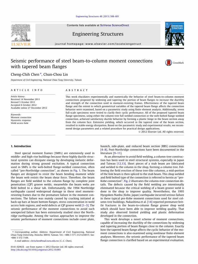
Steel special moment frames (SMFs) are extensively used inmiddle- and high-rise buildings because these highly ductile struc-tural systems can dissipate energy by developing inelastic defor-mation during strong ground excitation. A typical connectionused in SMFs is the web-bolted flange-welded connection, oftencalled ‘‘pre-Northridge connection’’, as shown in Fig. 1. The beamflanges are designed to resist the beam bending moment whilethe beam web resists the beam shear force. Therefore, the beamflanges are field welded to the column flange by complete jointpenetration (CJP) groove welds; meanwhile the beam webs arefield bolted to a shear tab. Unfortunately, the 1994 Northridgeearthquake caused widespread damage in these steel moment-resisting frames due to the premature failure in the moment con-nections. The failure was mainly caused by cracking initiated atback-up bars at beam bottom flanges, stress concentration in weldaccess hole regions, and weld defects at CJP groove weld [1–3]. Theseismic performance of the moment connections to avoid suchunexpected failure has been extensively studied since the North-ridge earthquake. Among the various approaches to improve theseismic performance of moment connections include cover plate,
haunch, side-plate, and reduced beam section (RBS) connections[4–8]. Post-Northridge connections have been documented in theliterature [9–11].
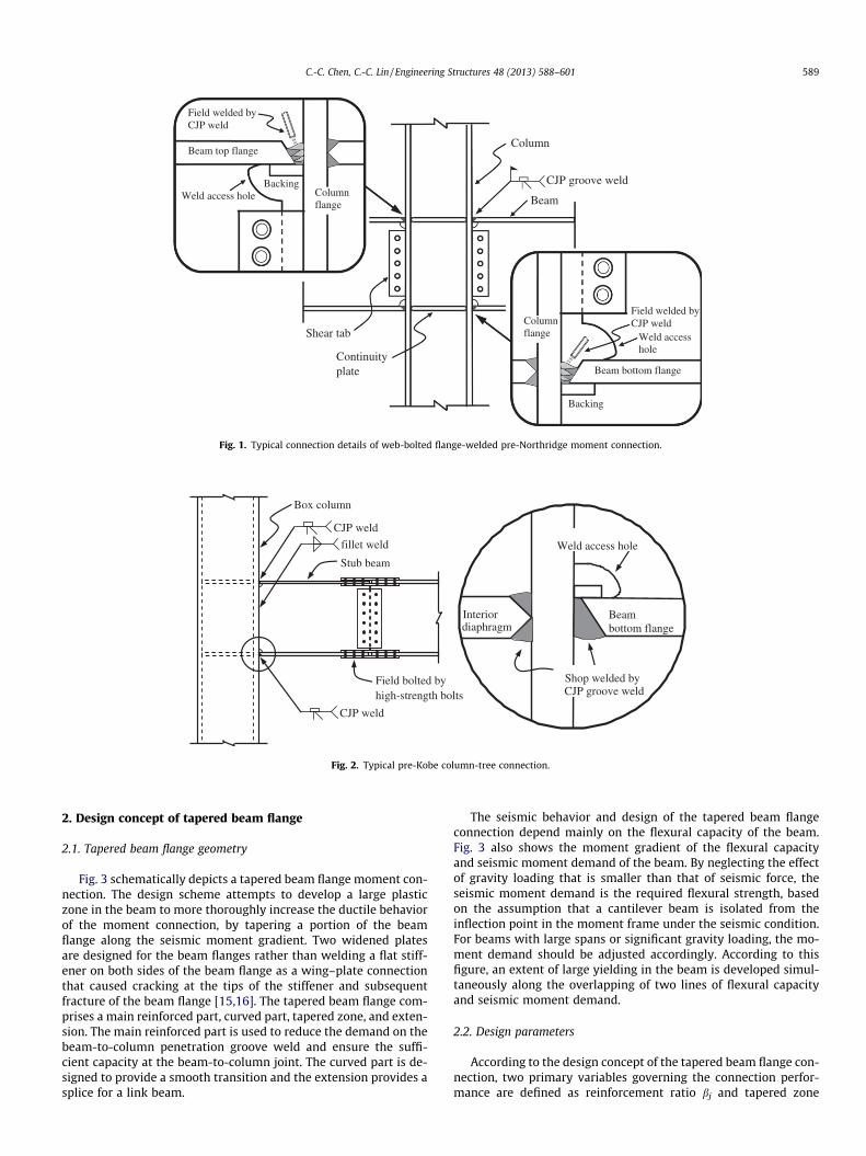
As an alternative to avoid field welding, a column-tree construc-tion has been used in steel structural systems, especially in Japanand Taiwan [12,13]. Short pieces of a stub beam are fabricatedand welded to the column in the shop, forming a column tree. Fol-lowing the field erection of these tree-like columns, a mid-portionof the link beam is then spliced to the stub beam. This shop weldedand field bolted type of the connection is referred to herein as ‘‘pre-Kobe connection’’. Fig. 2 illustrates the column-tree connection de-tails. The defects caused by the field welding are intentionallyeliminated because the critical welding of a beam groove weld isdone in the shop to improve quality. Nevertheless, the 1995Hyogoken-Nanbu (Kobe, Japan) earthquake incurred serious failurein these typical pre-Kobe moment connections used for steel col-umn-tree buildings. Nakashima et al. [14] reported premature brit-tle fractures in the beam-to-column flange groove shop weldwhich should have been able to improve welding quality. Thatstudy also observed limited yielding and plastic deformationdeveloped in the connection.
This work develops a novel scheme of moment connections,capable of increasing the ductility of the connections by wideningand tapering portion of beam flanges close to the column. Exactlyhow the tapered beam flange affects the cyclic behavior of the mo-ment connections is also examined using nonlinear finite elementanalyses. Moreover, the seismic performance of the tapered beamflange connection is clarified based on an experimental evaluation.
Beam
Column
Shear tab
Continuity plate
CJP groove weld
Beam bottom flange
Columnflange
Backing
Weld access hole
Field welded by CJP weld
Beam top flange
Field welded by CJP weld
Weld access hole Column flange
Backing
Fig. 1. Typical connection details of web-bolted flange-welded pre-Northridge moment connection.
Stub beam
Field bolted by high-strength bolts
Box column
CJP weld
fillet weld
CJP weld
Interiordiaphragm
Weld access hole
Beam bottom flange
Shop welded by CJP groove weld
Fig. 2. Typical pre-Kobe column-tree connection.
C.-C. Chen, C.-C. Lin / Engineering Structures 48 (2013) 588–601 589
2. Design concept of tapered beam flange
2.1. Tapered beam flange geometry
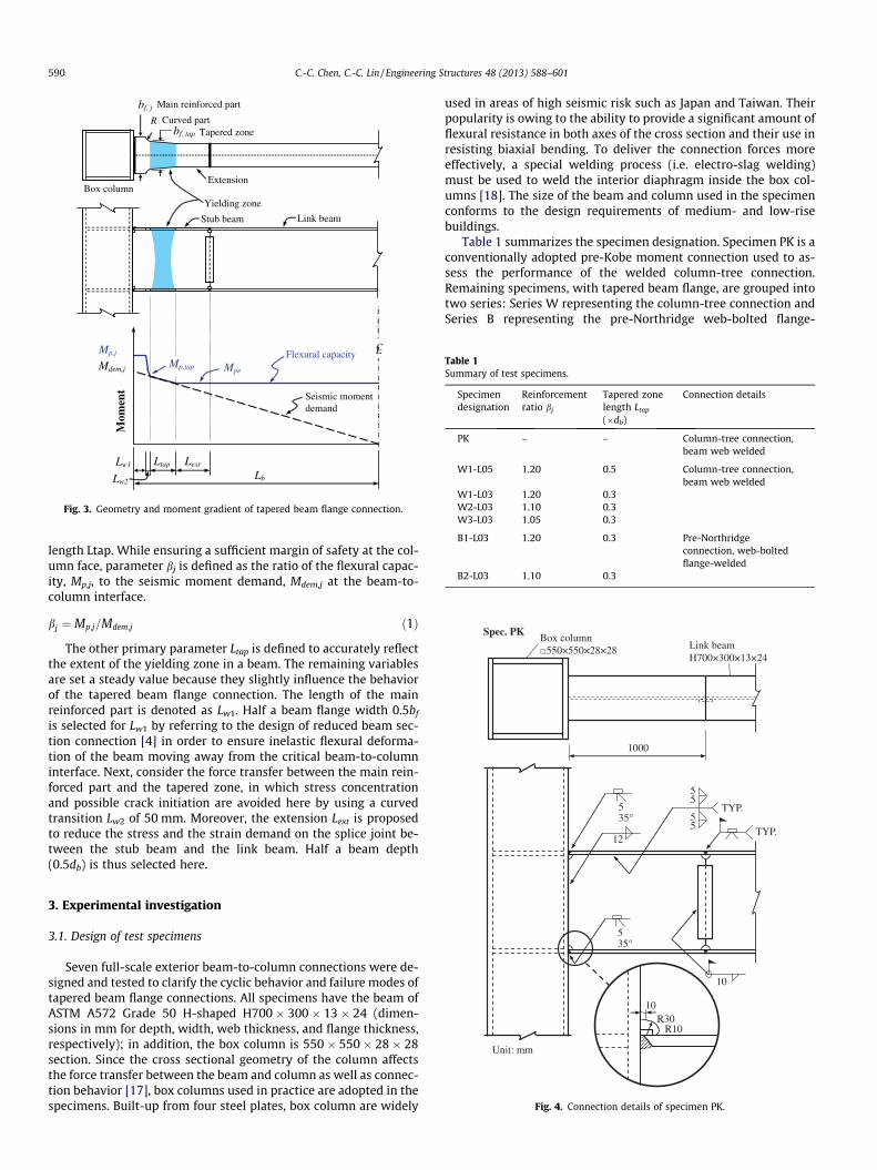
Fig. 3 schematically depicts a tapered beam flange moment con-nection. The design scheme attempts to develop a large plasticzone in the beam to more thoroughly increase the ductile behaviorof the moment connection, by tapering a portion of the beamflange along the seismic moment gradient. Two widened platesare designed for the beam flanges rather than welding a flat stiff-ener on both sides of the beam flange as a wing–plate connectionthat caused cracking at the tips of the stiffener and subsequentfracture of the beam flange [15,16]. The tapered beam flange com-prises a main reinforced part, curved part, tapered zone, and exten-sion. The main reinforced part is used to reduce the demand on thebeam-to-column penetration groove weld and ensure the suffi-cient capacity at the beam-to-column joint. The curved part is de-signed to provide a smooth transition and the extension provides asplice for a link beam.
The seismic behavior and design of the tapered beam flangeconnection depend mainly on the flexural capacity of the beam.Fig. 3 also shows the moment gradient of the flexural capacityand seismic moment demand of the beam. By neglecting the effectof gravity loading that is smaller than that of seismic force, theseismic moment demand is the required flexural strength, basedon the assumption that a cantilever beam is isolated from theinflection point in the moment frame under the seismic condition.For beams with large spans or significant gravity loading, the mo-ment demand should be adjusted accordingly. According to thisfigure, an extent of large yielding in the beam is developed simul-taneously along the overlapping of two lines of flexural capacityand seismic moment demand.
2.2. Design parameters
According to the design concept of the tapered beam flange con-nection, two primary variables governing the connection perfor-mance are defined as reinforcement ratio bj and tapered zone
Link beam
Box column
Flexural capacity Mp,j
Mdem,j
Seismic moment demand
Mpe
Stub beam
Main reinforced part
Curved part
Yielding zone
Ltap
C L
Mom
ent
Mp,tap
Lb
Lext Lw1
Lw2
bf, j
bf, tap
R
Extension
Tapered zone
Fig. 3. Geometry and moment gradient of tapered beam flange connection.
Table 1Summary of test specimens.
Specimendesignation
Reinforcementratio bj
Tapered zonelength Ltap
(�db)
Connection details
PK – – Column-tree connection,beam web welded
W1-L05 1.20 0.5 Column-tree connection,beam web welded
W1-L03 1.20 0.3W2-L03 1.10 0.3W3-L03 1.05 0.3
B1-L03 1.20 0.3 Pre-Northridgeconnection, web-boltedflange-welded
B2-L03 1.10 0.3
590 C.-C. Chen, C.-C. Lin / Engineering Structures 48 (2013) 588–601
length Ltap. While ensuring a sufficient margin of safety at the col-umn face, parameter bj is defined as the ratio of the flexural capac-ity, Mp,j, to the seismic moment demand, Mdem,j at the beam-to-column interface.
bj ¼ Mp;j=Mdem;j ð1Þ
The other primary parameter Ltap is defined to accurately reflectthe extent of the yielding zone in a beam. The remaining variablesare set a steady value because they slightly influence the behaviorof the tapered beam flange connection. The length of the mainreinforced part is denoted as Lw1. Half a beam flange width 0.5bf
is selected for Lw1 by referring to the design of reduced beam sec-tion connection [4] in order to ensure inelastic flexural deforma-tion of the beam moving away from the critical beam-to-columninterface. Next, consider the force transfer between the main rein-forced part and the tapered zone, in which stress concentrationand possible crack initiation are avoided here by using a curvedtransition Lw2 of 50 mm. Moreover, the extension Lext is proposedto reduce the stress and the strain demand on the splice joint be-tween the stub beam and the link beam. Half a beam depth(0.5db) is thus selected here.
Fig. 4. Connection details of specimen PK.
3. Experimental investigation
3.1. Design of test specimens
Seven full-scale exterior beam-to-column connections were de-signed and tested to clarify the cyclic behavior and failure modes oftapered beam flange connections. All specimens have the beam ofASTM A572 Grade 50 H-shaped H700 � 300 � 13 � 24 (dimen-sions in mm for depth, width, web thickness, and flange thickness,respectively); in addition, the box column is 550 � 550 � 28 � 28section. Since the cross sectional geometry of the column affectsthe force transfer between the beam and column as well as connec-tion behavior [17], box columns used in practice are adopted in thespecimens. Built-up from four steel plates, box column are widely
used in areas of high seismic risk such as Japan and Taiwan. Theirpopularity is owing to the ability to provide a significant amount offlexural resistance in both axes of the cross section and their use inresisting biaxial bending. To deliver the connection forces moreeffectively, a special welding process (i.e. electro-slag welding)must be used to weld the interior diaphragm inside the box col-umns [18]. The size of the beam and column used in the specimenconforms to the design requirements of medium- and low-risebuildings.
Table 1 summarizes the specimen designation. Specimen PK is aconventionally adopted pre-Kobe moment connection used to as-sess the performance of the welded column-tree connection.Remaining specimens, with tapered beam flange, are grouped intotwo series: Series W representing the column-tree connection andSeries B representing the pre-Northridge web-bolted flange-
C.-C. Chen, C.-C. Lin / Engineering Structures 48 (2013) 588–601 591
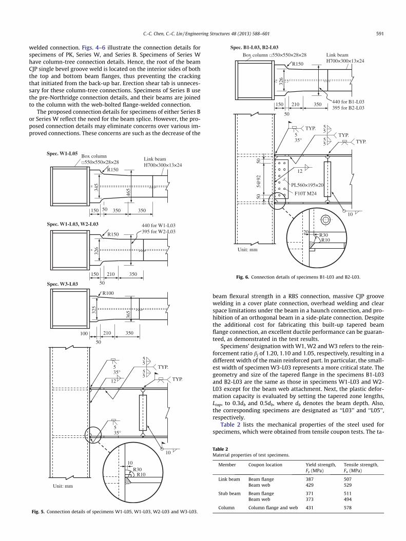
welded connection. Figs. 4–6 illustrate the connection details forspecimens of PK, Series W, and Series B. Specimens of Series Whave column-tree connection details. Hence, the root of the beamCJP single bevel groove weld is located on the interior sides of boththe top and bottom beam flanges, thus preventing the crackingthat initiated from the back-up bar. Erection shear tab is unneces-sary for these column-tree connections. Specimens of Series B usethe pre-Northridge connection details, and their beams are joinedto the column with the web-bolted flange-welded connection.
The proposed connection details for specimens of either Series Bor Series W reflect the need for the beam splice. However, the pro-posed connection details may eliminate concerns over various im-proved connections. These concerns are such as the decrease of the
Fig. 5. Connection details of specimens W1-L05, W1-L03, W2-L03 and W3-L03.
Fig. 6. Connection details of specimens B1-L03 and B2-L03.
beam flexural strength in a RBS connection, massive CJP groovewelding in a cover plate connection, overhead welding and clearspace limitations under the beam in a haunch connection, and pro-hibition of an orthogonal beam in a side-plate connection. Despitethe additional cost for fabricating this built-up tapered beamflange connection, an excellent ductile performance can be guaran-teed, as demonstrated in the test results.
Specimens’ designation with W1, W2 and W3 refers to the rein-forcement ratio bj of 1.20, 1.10 and 1.05, respectively, resulting in adifferent width of the main reinforced part. In particular, the small-est width of specimen W3-L03 represents a more critical state. Thegeometry and size of the tapered flange in the specimens B1-L03and B2-L03 are the same as those in specimens W1-L03 and W2-L03 except for the beam web attachment. Next, the plastic defor-mation capacity is evaluated by setting the tapered zone lengths,Ltap, to 0.3db and 0.5db, where db denotes the beam depth. Also,the corresponding specimens are designated as ‘‘L03’’ and ‘‘L05’’,respectively.
Table 2 lists the mechanical properties of the steel used forspecimens, which were obtained from tensile coupon tests. The ta-
Table 2Material properties of test specimens.
Member Coupon location Yield strength,Fy (MPa)
Tensile strength,Fu (MPa)
Link beam Beam flange 387 507Beam web 429 529
Stub beam Beam flange 371 511Beam web 373 494
Column Column flange and web 431 578
592 C.-C. Chen, C.-C. Lin / Engineering Structures 48 (2013) 588–601
pered beam flanges were fabricated by a thermal cutting processfrom a steel plate. The beam CJP groove welds for all specimenswere done by the gas metal arc welding process, using an electrodeof ER70S-G filler metal.
3.2. Test setup and loading history
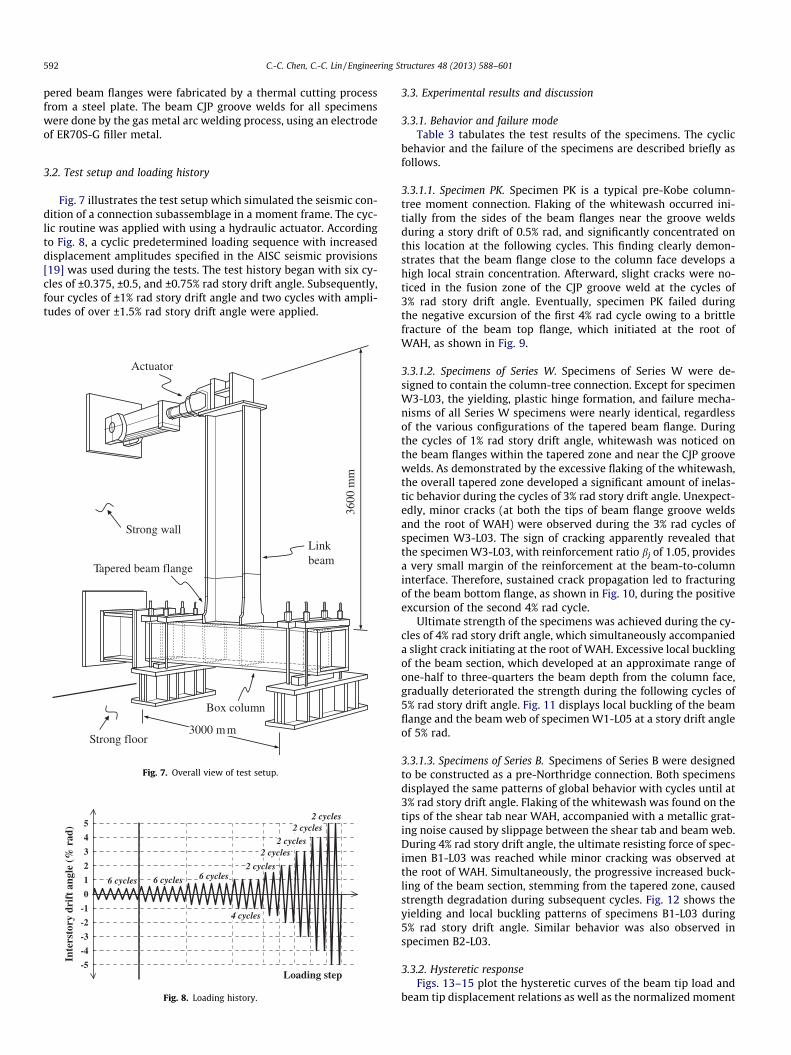
Fig. 7 illustrates the test setup which simulated the seismic con-dition of a connection subassemblage in a moment frame. The cyc-lic routine was applied with using a hydraulic actuator. Accordingto Fig. 8, a cyclic predetermined loading sequence with increaseddisplacement amplitudes specified in the AISC seismic provisions[19] was used during the tests. The test history began with six cy-cles of ±0.375, ±0.5, and ±0.75% rad story drift angle. Subsequently,four cycles of ±1% rad story drift angle and two cycles with ampli-tudes of over ±1.5% rad story drift angle were applied.
Link beam
Box column
Tapered beam flange
Actuator
3600
mm
3000 m mStrong floor
Strong wall
Fig. 7. Overall view of test setup.
-5
-4
-3
-2
-1
0
1
2
3
4
5
Inte
rsto
ry d
rift
ang
le (
% r
ad)
Loading step
6 cycles 6 cycles 6 cycles
4 cycles
2 cycles
2 cycles2 cycles
2 cycles
2 cycles
Fig. 8. Loading history.
3.3. Experimental results and discussion
3.3.1. Behavior and failure modeTable 3 tabulates the test results of the specimens. The cyclic
behavior and the failure of the specimens are described briefly asfollows.
3.3.1.1. Specimen PK. Specimen PK is a typical pre-Kobe column-tree moment connection. Flaking of the whitewash occurred ini-tially from the sides of the beam flanges near the groove weldsduring a story drift of 0.5% rad, and significantly concentrated onthis location at the following cycles. This finding clearly demon-strates that the beam flange close to the column face develops ahigh local strain concentration. Afterward, slight cracks were no-ticed in the fusion zone of the CJP groove weld at the cycles of3% rad story drift angle. Eventually, specimen PK failed duringthe negative excursion of the first 4% rad cycle owing to a brittlefracture of the beam top flange, which initiated at the root ofWAH, as shown in Fig. 9.
3.3.1.2. Specimens of Series W. Specimens of Series W were de-signed to contain the column-tree connection. Except for specimenW3-L03, the yielding, plastic hinge formation, and failure mecha-nisms of all Series W specimens were nearly identical, regardlessof the various configurations of the tapered beam flange. Duringthe cycles of 1% rad story drift angle, whitewash was noticed onthe beam flanges within the tapered zone and near the CJP groovewelds. As demonstrated by the excessive flaking of the whitewash,the overall tapered zone developed a significant amount of inelas-tic behavior during the cycles of 3% rad story drift angle. Unexpect-edly, minor cracks (at both the tips of beam flange groove weldsand the root of WAH) were observed during the 3% rad cycles ofspecimen W3-L03. The sign of cracking apparently revealed thatthe specimen W3-L03, with reinforcement ratio bj of 1.05, providesa very small margin of the reinforcement at the beam-to-columninterface. Therefore, sustained crack propagation led to fracturingof the beam bottom flange, as shown in Fig. 10, during the positiveexcursion of the second 4% rad cycle.
Ultimate strength of the specimens was achieved during the cy-cles of 4% rad story drift angle, which simultaneously accompanieda slight crack initiating at the root of WAH. Excessive local bucklingof the beam section, which developed at an approximate range ofone-half to three-quarters the beam depth from the column face,gradually deteriorated the strength during the following cycles of5% rad story drift angle. Fig. 11 displays local buckling of the beamflange and the beam web of specimen W1-L05 at a story drift angleof 5% rad.
3.3.1.3. Specimens of Series B. Specimens of Series B were designedto be constructed as a pre-Northridge connection. Both specimensdisplayed the same patterns of global behavior with cycles until at3% rad story drift angle. Flaking of the whitewash was found on thetips of the shear tab near WAH, accompanied with a metallic grat-ing noise caused by slippage between the shear tab and beam web.During 4% rad story drift angle, the ultimate resisting force of spec-imen B1-L03 was reached while minor cracking was observed atthe root of WAH. Simultaneously, the progressive increased buck-ling of the beam section, stemming from the tapered zone, causedstrength degradation during subsequent cycles. Fig. 12 shows theyielding and local buckling patterns of specimens B1-L03 during5% rad story drift angle. Similar behavior was also observed inspecimen B2-L03.
3.3.2. Hysteretic responseFigs. 13–15 plot the hysteretic curves of the beam tip load and
beam tip displacement relations as well as the normalized moment
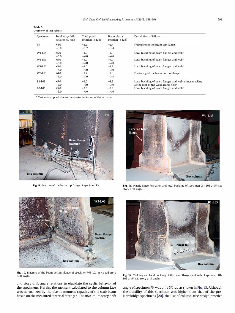
Table 3Overview of test results.
Specimen Total story driftrotation (% rad)
Total plasticrotation (% rad)
Beam plasticrotation (% rad)
Description of failure
PK +4.0 +2.6 +2.4 Fracturing of the beam top flange�3.0 �1.7 �1.4
W1-L05 +5.0 +3.9 +3.9 Local buckling of beam flanges and weba
�5.0 �4.0 �4.0W1-L03 +5.0 +4.0 +4.0 Local buckling of beam flanges and weba
�5.0 �4.0 �4.0W2-L03 +5.0 +4.0 +3.9 Local buckling of beam flanges and weba
�5.0 �4.0 �3.9W3-L03 +4.0 +2.7 +2.6 Fracturing of the beam bottom flange
�5.0 �3.9 �3.8
B1-L03 +5.0 +4.0 +3.9 Local buckling of beam flanges and web, minor crackingat the root of the weld access holea�5.0 �4.0 �3.9
B2-L03 +5.0 +3.9 +3.9 Local buckling of beam flanges and weba
�5.0 �4.0 �4.0
a Test was stopped due to the stroke limitation of the actuator.
PK
Box column
Beam flange fracture
Fig. 9. Fracture of the beam top flange of specimen PK.
W3-L03
Beam flange fracture
Tapered beam flange
Weld access hole
Box column
Fig. 10. Fracture of the beam bottom flange of specimen W3-L03 at 4% rad storydrift angle.
W1-L05
Box column
Tapered beam flange
Fig. 11. Plastic hinge formation and local buckling of specimen W1-L05 at 5% radstory drift angle.
B1-L03
Box column
Shear tab
Fig. 12. Yielding and local buckling of the beam flanges and web of specimen B1-L03 at 5% rad story drift angle.
C.-C. Chen, C.-C. Lin / Engineering Structures 48 (2013) 588–601 593
and story drift angle relations to elucidate the cyclic behavior ofthe specimens. Herein, the moment calculated to the column facewas normalized by the plastic moment capacity of the stub beambased on the measured material strength. The maximum story drift
angle of specimen PK was only 3% rad as shown in Fig. 13. Althoughthe ductility of this specimen was higher than that of the pre-Northridge specimens [20], the use of column-tree design practice
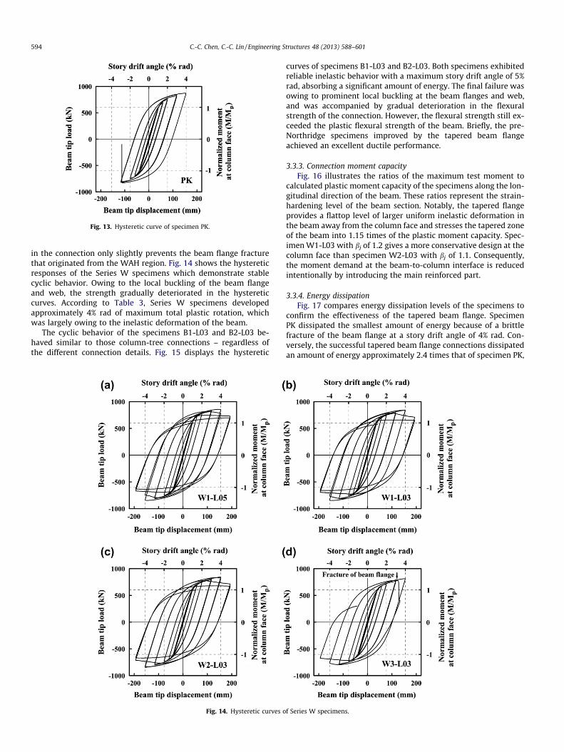
Fig. 13. Hysteretic curve of specimen PK.
594 C.-C. Chen, C.-C. Lin / Engineering Structures 48 (2013) 588–601
in the connection only slightly prevents the beam flange fracturethat originated from the WAH region. Fig. 14 shows the hystereticresponses of the Series W specimens which demonstrate stablecyclic behavior. Owing to the local buckling of the beam flangeand web, the strength gradually deteriorated in the hystereticcurves. According to Table 3, Series W specimens developedapproximately 4% rad of maximum total plastic rotation, whichwas largely owing to the inelastic deformation of the beam.
The cyclic behavior of the specimens B1-L03 and B2-L03 be-haved similar to those column-tree connections – regardless ofthe different connection details. Fig. 15 displays the hysteretic
Fig. 14. Hysteretic curves o
curves of specimens B1-L03 and B2-L03. Both specimens exhibitedreliable inelastic behavior with a maximum story drift angle of 5%rad, absorbing a significant amount of energy. The final failure wasowing to prominent local buckling at the beam flanges and web,and was accompanied by gradual deterioration in the flexuralstrength of the connection. However, the flexural strength still ex-ceeded the plastic flexural strength of the beam. Briefly, the pre-Northridge specimens improved by the tapered beam flangeachieved an excellent ductile performance.
3.3.3. Connection moment capacityFig. 16 illustrates the ratios of the maximum test moment to
calculated plastic moment capacity of the specimens along the lon-gitudinal direction of the beam. These ratios represent the strain-hardening level of the beam section. Notably, the tapered flangeprovides a flattop level of larger uniform inelastic deformation inthe beam away from the column face and stresses the tapered zoneof the beam into 1.15 times of the plastic moment capacity. Spec-imen W1-L03 with bj of 1.2 gives a more conservative design at thecolumn face than specimen W2-L03 with bj of 1.1. Consequently,the moment demand at the beam-to-column interface is reducedintentionally by introducing the main reinforced part.
3.3.4. Energy dissipationFig. 17 compares energy dissipation levels of the specimens to
confirm the effectiveness of the tapered beam flange. SpecimenPK dissipated the smallest amount of energy because of a brittlefracture of the beam flange at a story drift angle of 4% rad. Con-versely, the successful tapered beam flange connections dissipatedan amount of energy approximately 2.4 times that of specimen PK,
f Series W specimens.

Fig. 15. Hysteretic curves of Series B specimens.
PK
W1-L03
W2-L03
0 250 500 750 1000 1250
Distance from column face (mm)
0.0
0.5
1.0
1.5
Tes
t m
omen
t /C
apac
ity
(Mte
st/M
p)
1.15
Tapered zone
Fig. 16. Ratios of maximum test moment to calculated moment capacity ofspecimens PK, W1-L03 and W2-L03 along the beam longitudinal direction.
762
1796 1820 17711797 1780
1091
0
500
1000
1500
2000
2500
Ene
rgy
diss
ipat
ion
(kN
-m)
Specimen
B2-L03
W2-
L03
B1-L03
W1-
L03
W1-
L05PK
W3-
L03
Fig. 17. Comparison of energy dissipation of the specimens.
C.-C. Chen, C.-C. Lin / Engineering Structures 48 (2013) 588–601 595
due to the stable and full hysteretic loops of the specimens. Com-paring specimen W1-L03 with W1-L05 reveals a highly similar en-ergy dissipation for these two specimens. Additionally, increasingthe length of the tapered beam flange from 0.3db to 0.5db slightlyaffected the connection behavior. Furthermore, although differentdetails of the beam web attachment were used, specimens of SeriesW and B dissipated a similar amount of energy. This observationclearly indicates that applying the tapered flange can significantly
improve the ductility of the specimens, either the column-treeconnection or the web-bolted flange-welded connection.
4. Finite element analysis
4.1. Finite element modeling
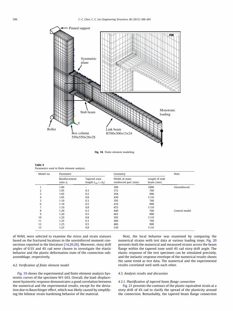
Based on a general-purpose nonlinear finite element analysisprogram ANSYS [21], various configurations of the tapered beamflange connection were modeled and analyzed. Exactly how designparameters affect the connection behavior was also more closelyexamined. The finite element models of the connection subassem-blage consisted of three-dimensional structural solid elementswith 24 nodal degrees of freedom. Fig. 18 shows the finite elementmeshes and boundary conditions of the model. Due to the struc-tural symmetry with respect to the mid-plane at the beam weband the column section, only half of the connection subassemblagewas modeled to reduce the computational effort. According toTable 4, 13 models were designed for detailed evaluation. An unre-inforced connection was modeled to represent the conventionalmoment connection, while other models with various configura-tions of the tapered beam flange were designed to clarify the effec-tiveness of the tapered beam flange on the connection behavior. Acontrol model of the tapered beam flange connection used param-eter bj of 1.2 and Ltap of 0.3db. Table 4 also lists the dimensions ofthe tapered beam flange used in models with the flange width ofthe main reinforced part ranging from 372 to 530 mm and the stubbeam length ranging from 760 to 1110 mm.
For simplification, the stress–strain relations of the structuralsteel and the weld were simulated based on bilinear isotropichardening behavior. In particular, a rate-independent plasticitymodel was used to analyze the inelastic behavior. Moreover, plas-tification of the models was determined using the von Mises yield-ing criterion with the associated flow rule. Furthermore, theisotropic hardening rule was used for monotonic analysis, andkinematic hardening behavior of the structural steel was assumedfor cyclic analysis.
The potential for cracking was evaluated based on a tendency ofstress and strain states at different levels of a story drift angle.According to previous works [22–25], von Mises stress and equiv-alent plastic strain were used as the indicators of the potential forplasticity in ductile materials. Undoubtedly, a higher PEEQ implieda higher demand for a plastic strain. Meanwhile, the principalstress was normalized by yield strength Fy, while PEEQ dividedby the yield strain ey defined as the PEEQ index. Two critical sec-tions of the connection, along the beam flange width at the loca-tions of the complete joint penetration groove weld and the root
Monotonicloading
Link beam H700×300×13×24Box column
550×550×28×28
Roller
Pinned support
Symmetric plane
Stub beam
Fig. 18. Finite element modeling.
Table 4Parameters used in finite element analysis.
Model no. Parameter Geometry Note
Reinforcementratio bj
Tapered zonelength Ltap (�db)
Width of mainreinforced part (mm)
Length of stubbeam (mm)
1 1.00 – 300 1000 Unreinforced2 1.05 0.3 372 7603 1.05 0.5 394 9004 1.05 0.8 430 11105 1.10 0.3 395 7606 1.10 0.5 416 9007 1.10 0.8 455 11108 1.20 0.3 440 760 Control model9 1.20 0.5 463 900
10 1.20 0.8 505 111011 1.25 0.3 460 76012 1.25 0.5 486 90013 1.25 0.8 530 1110
596 C.-C. Chen, C.-C. Lin / Engineering Structures 48 (2013) 588–601
of WAH, were selected to examine the stress and strain statusesbased on the fractured locations in the unreinforced moment con-nections reported in the literature [14,20,26]. Moreover, story driftangles of 0.5% and 4% rad were chosen to investigate the elasticbehavior and the plastic deformation state of the connection sub-assemblage, respectively.
4.2. Verification of finite element model
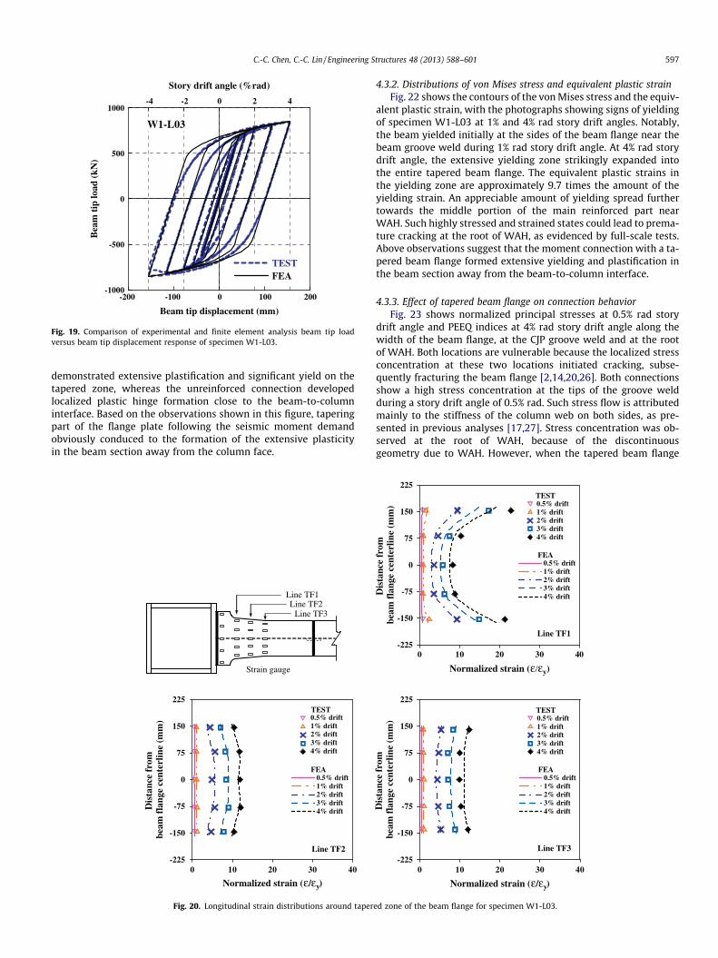
Fig. 19 shows the experimental and finite element analysis hys-teretic curves of the specimen W1-L03. Overall, the load–displace-ment hysteretic response demonstrates a good correlation betweenthe numerical and the experimental results, except for the devia-tion due to Bauschinger effect, which was likely caused by simplify-ing the bilinear strain-hardening behavior of the material.
Next, the local behavior was examined by comparing thenumerical strains with test data at various loading steps. Fig. 20presents both the numerical and measured strains across the beamflange within the tapered zone until 4% rad story drift angle. Theelastic response of the test specimen can be simulated precisely,and the inelastic response envelope of the numerical results showsthe same trend as test data. The numerical and the experimentalresults correlated well with each other.
4.3. Analysis results and discussion
4.3.1. Plastification of tapered beam flange connectionFig. 21 presents the contours of the plastic equivalent strain at a
story drift of 4% rad to clarify the spread of the plasticity aroundthe connection. Remarkably, the tapered beam flange connection
-200 -100 0 100 200
Beam tip displacement (mm)
-1000
-500
0
500
1000
Bea
m t
ip lo
ad (
kN)
-4 -2 0 2 4
Story drift angle (%rad)
TESTFEA
W1-L03
Fig. 19. Comparison of experimental and finite element analysis beam tip loadversus beam tip displacement response of specimen W1-L03.
C.-C. Chen, C.-C. Lin / Engineering Structures 48 (2013) 588–601 597
demonstrated extensive plastification and significant yield on thetapered zone, whereas the unreinforced connection developedlocalized plastic hinge formation close to the beam-to-columninterface. Based on the observations shown in this figure, taperingpart of the flange plate following the seismic moment demandobviously conduced to the formation of the extensive plasticityin the beam section away from the column face.
Line TF1
Strain gauge
Line TF3 Line TF2
0 10 20 30 40
Normalized strain (ε/εy)
-225
-150
-75
0
75
150
225
Dis
tanc
e fr
om
beam
fla
nge
cent
erlin
e (m
m)
TEST0.5% drift1% drift2% drift3% drift4% drift
FEA0.5% drift1% drift2% drift3% drift4% drift
Line TF2
Fig. 20. Longitudinal strain distributions around taper
4.3.2. Distributions of von Mises stress and equivalent plastic strainFig. 22 shows the contours of the von Mises stress and the equiv-
alent plastic strain, with the photographs showing signs of yieldingof specimen W1-L03 at 1% and 4% rad story drift angles. Notably,the beam yielded initially at the sides of the beam flange near thebeam groove weld during 1% rad story drift angle. At 4% rad storydrift angle, the extensive yielding zone strikingly expanded intothe entire tapered beam flange. The equivalent plastic strains inthe yielding zone are approximately 9.7 times the amount of theyielding strain. An appreciable amount of yielding spread furthertowards the middle portion of the main reinforced part nearWAH. Such highly stressed and strained states could lead to prema-ture cracking at the root of WAH, as evidenced by full-scale tests.Above observations suggest that the moment connection with a ta-pered beam flange formed extensive yielding and plastification inthe beam section away from the beam-to-column interface.
4.3.3. Effect of tapered beam flange on connection behaviorFig. 23 shows normalized principal stresses at 0.5% rad story
drift angle and PEEQ indices at 4% rad story drift angle along thewidth of the beam flange, at the CJP groove weld and at the rootof WAH. Both locations are vulnerable because the localized stressconcentration at these two locations initiated cracking, subse-quently fracturing the beam flange [2,14,20,26]. Both connectionsshow a high stress concentration at the tips of the groove weldduring a story drift angle of 0.5% rad. Such stress flow is attributedmainly to the stiffness of the column web on both sides, as pre-sented in previous analyses [17,27]. Stress concentration was ob-served at the root of WAH, because of the discontinuousgeometry due to WAH. However, when the tapered beam flange
0 10 20 30 40
Normalized strain (ε/εy)
-225
-150
-75
0
75
150
225
Dis
tanc
e fr
om
beam
fla
nge
cent
erlin
e (m
m)
TEST0.5% drift1% drift2% drift3% drift4% drift
FEA0.5% drift1% drift2% drift3% drift4% drift
Line TF1
0 10 20 30 40
Normalized strain (ε/εy)
-225
-150
-75
0
75
150
225
Dis
tanc
e fr
om
beam
fla
nge
cent
erlin
e (m
m)
TEST0.5% drift1% drift2% drift3% drift4% drift
FEA0.5% drift1% drift2% drift3% drift4% drift
Line TF3
ed zone of the beam flange for specimen W1-L03.
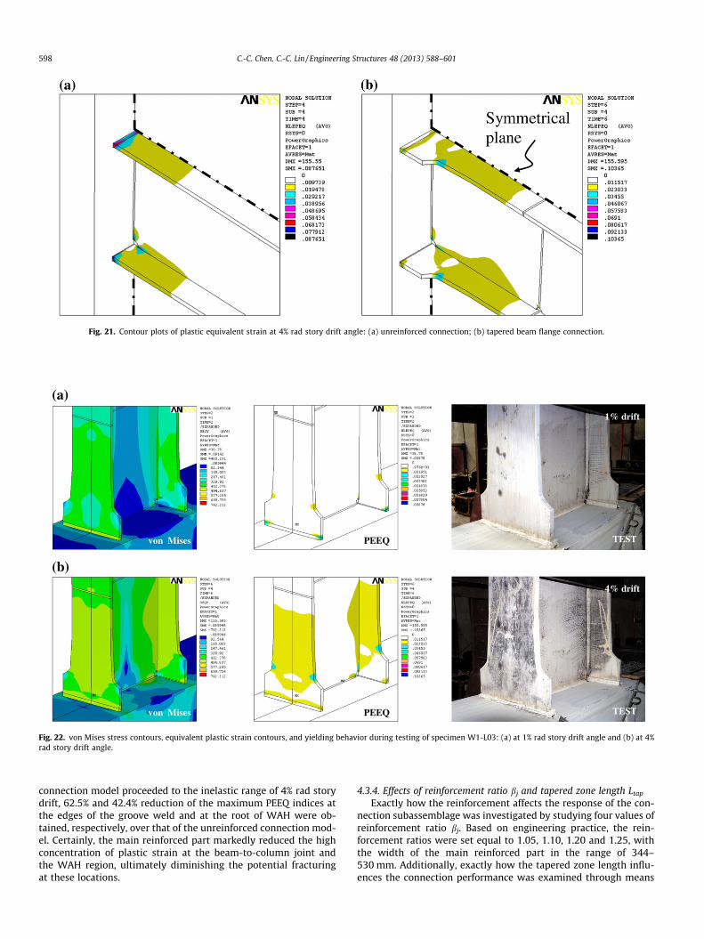
Fig. 21. Contour plots of plastic equivalent strain at 4% rad story drift angle: (a) unreinforced connection; (b) tapered beam flange connection.
(a) 1% drift
von Mises PEEQ TEST
(b) 4% drift
von Mises PEEQ TEST
Fig. 22. von Mises stress contours, equivalent plastic strain contours, and yielding behavior during testing of specimen W1-L03: (a) at 1% rad story drift angle and (b) at 4%rad story drift angle.
598 C.-C. Chen, C.-C. Lin / Engineering Structures 48 (2013) 588–601
connection model proceeded to the inelastic range of 4% rad storydrift, 62.5% and 42.4% reduction of the maximum PEEQ indices atthe edges of the groove weld and at the root of WAH were ob-tained, respectively, over that of the unreinforced connection mod-el. Certainly, the main reinforced part markedly reduced the highconcentration of plastic strain at the beam-to-column joint andthe WAH region, ultimately diminishing the potential fracturingat these locations.
4.3.4. Effects of reinforcement ratio bj and tapered zone length Ltap
Exactly how the reinforcement affects the response of the con-nection subassemblage was investigated by studying four values ofreinforcement ratio bj. Based on engineering practice, the rein-forcement ratios were set equal to 1.05, 1.10, 1.20 and 1.25, withthe width of the main reinforced part in the range of 344–530 mm. Additionally, exactly how the tapered zone length influ-ences the connection performance was examined through means

(a)
-200 -100 0 100 200
Distance from beam f lange centerline (mm)
0.0
0.5
1.0
1.5
Nor
mal
ized
pri
ncip
al s
tres
s ( σ
1/F y
)
Pre-KobeTapered
1.12 1.11
CJP weld
-200 -100 0 100 200
Distance from beam f lange centerline (mm)
0.0
0.5
1.0
1.5
Nor
mal
ized
pri
ncip
al s
tres
s (σ
1/F y
)
Pre-KobeTapered
0.85
0.76
Root of WAH
(b)
-200 -100 0 100 200
Distance from beam flange centerline (mm)
0
10
20
30
40
PE
EQ
inde
x
Pre-KobeTapered28.0
10.5
CJP weld
-200 -100 0 100 200
Distance from beam flange centerline (mm)
0
10
20
30
40
PE
EQ
inde
x
Pre-KobeTapered
21.7
12.5
Root of WAH
Fig. 23. Distributions of normalized principal stresses and PEEQ indices along beam flange width at the CJP weld and root of WAH: (a) normalized principal stresses at 0.5%rad story drift angle and (b) PEEQ indices at 4% rad story drift angle.
1.0 1.1 1.2 1.3
Parameter βj
0
10
20
30
40
PE
EQ
inde
x
Ltap= 0.3db
Ltap= 0.5db
Ltap= 0.8db
Pre-Kobe type
28.02
Sides of CJP weld
1.0 1.1 1.2 1.3
Parameter βj
0
10
20
30
40
PE
EQ
inde
x
Ltap = 0.3db
Ltap = 0.5db
Ltap = 0.8db
Pre-Kobe type
21.65
Root of WAH(a) (b)
Fig. 24. Effect of parameters of reinforcement ratiobj and tapered zone length Ltap on PEEQ indices at 4% rad story drift angle: (a) at the CJP weld and (b) at root of WAH.
C.-C. Chen, C.-C. Lin / Engineering Structures 48 (2013) 588–601 599
of varying design parameter Ltap by changing the tapered zonelength from 0.3db to 0.8db, ranging from 210 to 560 mm. Fig. 24summarizes the finite element analysis results. Undoubtedly, thePEEQ indices of the connections were reduced by using the taperedbeam flange. The higher reinforcement ratio caused a lower plasticstrain demand, resulting in a higher margin of safety at the junc-tion of the beam-to-column connection. Furthermore, using thelarger tapered zone also lowered the PEEQ index. According toFig. 24, the model with reinforcement ratio bj of 1.05 developedthe largest value of PEEQ index at the CJP groove weld that implies
the brittle fracture of the beam flange of specimen W3-L03. Basedon experimental results and for practical implications, the value ofreinforcement ratio bj can be set to 1.1 or higher and the taperedzone length of 0.3db can be used.
5. Design considerations
To simplify the design, the thicknesses of the beam flange andweb, and beam depth of the tapered beam flange connection are
600 C.-C. Chen, C.-C. Lin / Engineering Structures 48 (2013) 588–601
intentionally assumed to be the same as those of the beam. Basedon the parametric study and experimental results, the designparameters of Lw1 = 0.5bf, Lw2 = 50 mm, and Ltap = 0.3db can be usedin practice. The design procedure to configure the tapered beamflange is summarized as follows.
First, the expected plastic moment of the beam, Mpe, iscalculated:
Mpe ¼ RyFyZb ð2Þ
where RyFy denotes the expected yield strength; Ry is the ratio of theexpected yield strength to the specified minimum yield strength, inaccordance with AISC seismic provisions [19]; and Zb represents theplastic section modulus of the beam.
Second, the maximum width of the tapered beam flange, bf,tap, isdetermined by calculating the design flexural capacity at this loca-tion, Mp,tap, which can be determined based on the moment gradi-ent diagram shown in Fig. 3.
Mp;tap ¼Lb � ðLw1 þ Lw2Þ
Lb � ðLw1 þ Lw2 þ LtapÞMpe ð3Þ
where Lb refers to the length of the half clear span of the beam.Third, the width of the main reinforced part, bf,j, is designed
based on the design flexural capacity at the beam-to-column joint,Mp,j, which can be determined as
Mp;j ¼ bjMdem;j ð4Þ
where Mdem,j denotes the moment demand of the beam at thebeam-to-column joint, and can be calculated as
Mdem;j ¼Lb
Lb � ðLw1 þ Lw2 þ LtapÞMpe ð5Þ
According to test results, parameter bj can be set to 1.1 or great-er to prevent failure at the beam flange groove weld and the WAHregion.
Additionally, the shear demand of the bolted web connection atthe beam-to-column joint, Vdem,j, must be determined to ensuresufficient capacity at this critical section. Design shear for the sheartab and bolts can be calculated as
Vdem;j ¼Mdem;j
Lbþ Vg ð6Þ
where Vg is the shear at the column face due to factored gravityloads.
Moreover, a smooth force transfer can be made using the radiusof the curved part R = Lw1. Additionally, the extension length, Lext,can be selected at least 0.5db to provide a sufficient margin ofsafety at the splice. Moreover, because the tapered beam flange in-creases the flexural strength of the beam, the seismic designrequirements for a strong-column weak-beam criterion should bechecked for designing the tapered beam flange connection.
6. Conclusions
Based on experimental and finite element analysis results forunreinforced pre-Kobe connection and tapered beam flange con-nections, we conclude the following:
1. While occurring at either the tips of the beam flange groovewelds or the root of the weld access hole region, concentratedprincipal stresses and plastic equivalent strains were noticedin the unreinforced pre-Kobe connection. This appearance ofthe localized stress and strain resulted in the crack initiationand subsequent beam flange fracture.
2. The tapered beam flange can develop an extensive plastificationspread around the tapered zone of the beam away from the col-umn face, in addition to diminishing the stress concentration
and plastic strain demand in the beam groove weld and theweld access hole region by using the main reinforced part.
3. Test results of the unreinforced pre-Kobe connection specimenrevealed moderate ductile behavior of 2.6% rad plastic rotation.However, the specimen still failed in brittle beam flange frac-ture at a story drift angle of 4% rad due to cracks initiated at tipsof the beam groove weld and in the toe of the weld access hole.
4. Experimental results demonstrated that all tapered beam flangespecimens, with either column-tree connection (Series W) orpre-Northridge web-bolted flange-welded connection (SeriesB), can develop a sufficient rotation of story drift angle, satisfy-ing the requirements for connections used in special momentframes.
5. The parametric study indicated that the behavior of a taperedbeam flange connection is influenced mainly by the reinforce-ment ratio at the beam-to-column joint and the tapered zonelength. A larger reinforcement ratio increases the capacity atthe CJP groove welds, resulting in a higher margin of safety atthe beam-to-column joint. The longer tapered zone of the beamflange leads to a lower plastic strain demand at the CJP groovewelds and the weld access hole region.
Acknowledgement
The authors would like to thank the National Science Council ofthe Republic of China, Taiwan, for financially supporting thisresearch.
References
[1] Tremblay R, Timler P, Bruneau M, Filiatrault A. Performance of steel structuresduring the 1994 Northridge earthquake. Can J Civil Eng 1995;22:338–60.
[2] Miller DK. Lessons learned from the Northridge earthquake. Eng Struct1998;20(4–6):249–60.
[3] Mahin ST. Lessons from damage to steel buildings during the Northridgeearthquake. Eng Struct 1998;20(4–6):261–70.
[4] Engelhardt MD, Winneberger T, Zekany AJ, Potyraj TJ. Experimentalinvestigation of dogbone moment connections. Eng J AISC 1998;35(4):128–39.
[5] Uang CM, Bondad D, Lee CH. Cyclic performance of haunch repaired steelmoment connections: experimental testing and analytical modeling. EngStruct 1998;20(4–6):552–61.
[6] Engelhardt MD, Sabol TA. Reinforcing of steel moment connections with coverplates: benefits and limitations. Eng Struct 1998;20(4–6):510–20.
[7] Azuma K, Kurobane Y, Makino Y. Cyclic testing of beam-to-columnconnections with weld defects and assessment of safety of numericallymodeled connections from brittle fracture. Eng Struct 2000;22:1596–608.
[8] Lu LW, Ricles JM, Mao C, Fisher JW. Critical issues in achieving ductilebehaviour of welded moment connections. J Constr Steel Res 2000;55(1–3):325–41.
[9] FEMA-350. Recommended seismic design criteria for new steel moment-framebuildings. Washington (DC): Federal Emergency Management Agency; 2000.
[10] ANSI/AISC 358. Prequalified connections for special and intermediate steelmoment frames for seismic applications. Chicago (IL): American Institute ofSteel Construction, Inc.; 2005.
[11] SAC Joint Venture. Interim guidelines: evaluation, repair, modification anddesign of steel moment frames, report no. SAC-95-02. Sacramento, CA: SACJoint Venture; 1995.
[12] Nakashima M, Suita K, Morisako K, Maruoka Y. Tests of welded beam–column subassemblies, I: Global behavior. J Struct Eng, ASCE1998;124(11):1236–44.
[13] McMullin KM, Astaneh-Asl A. Steel semirigid column-tree moment resistingframe seismic behavior. J Struct Eng, ASCE 2003;129(9):1243–9.
[14] Nakashima M, Inoue K, Tada M. Classification of damage to steel buildingsobserved in the 1995 Hyogoken-Nanbu earthquake. Eng Struct 1998;20(4–6):271–81.
[15] Zepeda JA, Itani AM, Sahai R. Cyclic behavior of steel moment frameconnections under varying axial load and lateral displacements. J ConstrSteel Res 2003;59:1–25.
[16] Sugimoto H, Morita K, Takahashi Y. Prediction of failure mode of hunchedbeam to SHS column connections. Int J Steel Struct 2001;1(3):185–99.
[17] Roeder CW. General issues influencing connection performance. J Struct EngASCE 2002;128(4):420–8.
[18] Chen CC, Lin CC, Tsai CL. Evaluation of reinforced connections between steelbeams and box columns. Eng Struct 2004;26(13):1889–904.

C.-C. Chen, C.-C. Lin / Engineering Structures 48 (2013) 588–601 601
[19] American Institute of Steel Construction (AISC). Seismic provisions forstructural steel buildings. Chicago (IL): American Institute of SteelConstruction, Inc.; 2005.
[20] Chen CC, Chen SW, Chung MD, Lin MC. Cyclic behaviour of unreinforced andrib-reinforced moment connections. J Constr Steel Res 2005;61(1):1–21.
[21] ANSYS user manual. Swanson Analysis Systems, Inc.; 2002.[22] Popov EP, Yang TS, Chang SP. Design of steel MRF connections before and after
1994 Northridge earthquake. Eng Struct 1998;20(12):1030–8.[23] EI-Tawil S, Mikesell T, Kunnath SK. Effect of local details and yield ratio on
behavior of FR steel connections. J Struct Eng ASCE 2000;126(1):79–87.
[24] Mao C, Ricles J, Lu LW, Fisher J. Effect of local details on ductility of weldedmoment connections. J Struct Eng, ASCE 2001;127(9):1036–44.
[25] Chen CC, Lu CA, Lin CC. Parametric study and design of rib-reinforced steelmoment connections. Eng Struct 2005;27(5):699–708.
[26] Stojadinovic B, Goel SC, Lee KH, Margarian AG, Choi JH. Parametric tests onunreinforced steel moment connections. J Struct Eng, ASCE 2000;126(1):40–9.
[27] Kim T, Stojadinovic B, Whittaker AS. Seismic performance of US steel boxcolumn connections. In: Proc 13th world conference on earthquake eng.Canada; 2004 [paper no. 981].