SEISMIC ISOLATION OF TAIPEI PERFORMING ART … · SEISMIC ISOLATION OF TAIPEI PERFORMING ART CENTER...
12
1 SEISMIC ISOLATION OF TAIPEI PERFORMING ART CENTER Hüseyin DARAMA 1 , Atila ZEKİOĞLU 2 , Simon REES 3 , Chas POPE 4 and Rory McGowan 5 ABSTRACT This paper describes the performance-based seismic design of the Taipei Performing Art Center (TPAC) in Taiwan, utilizing seismic-isolation concept with friction-pendulum devices. TPAC will be the new international-standard performing arts facility for the capital of Taiwan. The design, by the Office for Metropolitan Architecture (OMA), was the winner in a two-stage international design competition held in 2008, and was selected from a total of 135 entries from 24 countries (Figure 1). TPAC is a public project for the city of Taipei and situated in a busy urban location. The site currently contains a street food market, and is adjacent to the famous Shilin Night Market as well as a mass- transit station. TPAC, at over 40,000 square meters, is believed to be the first use of friction pendulum isolators in Taiwan. The building’s complex geometry and irregular mass distribution led to the realization that the most-efficient and direct way to achieve the required performance in such a highly seismic area would be to base isolate the superstructure. The irregularity also led to the decision to use Friction Pendulum (FP) type isolators. These are considered to have better structural performance compared to alternatives due to higher damping and lower base shear forces, simpler connection detailing at the isolation plane, and inherent self-centering behaviour. In the proposed structural scheme, 89 isolators (located at basement level) work in conjunction with the steel braced superstructure to give the most efficient, economic, and highest performance building possible for the challenging site location. The structural system was analysed using equivalent static, linear dynamic and time history procedures, including a "beyond the code requirement” investigation of the structural members at MCE hazard with recommended acceptance criteria per the selected performance objectives. A comparative study is performed showing the effectiveness of the current code based analysis and design procedures. In overall, the seismically isolated structure met and surpassed the performance objectives while achieving a 60% reduction in the base shear, significant decrease in story drift and floor accelerations. Construction started in February 2012 and the center is scheduled to open in 2015. Taipei city council expects the centre to further facilitate the development of local performing groups and add to Taipei’s image as an international cultural hub. INTRODUCTION TPAC is a public project for the city of Taipei. The Client is the Department of Cultural Affairs, Taipei City Government. It is one of a series of cultural projects commissioned in Taiwan recently, including Taichung Metropolitan Opera House, designed by Toyo Ito with Arup and currently under construction, and Taipei Pop Music Centre, for which the design competition was recently won by 1 Associate, Ove Arup and Partners, Los Angeles CA, USA, [email protected] 2 Americas Building Practice Leader, Ove Arup and Partners, Los Angeles CA, USA, [email protected] 3 Associate Principle, Ove Arup and Partners, Los Angeles CA, USA, [email protected] 4 Associate Director, Ove Arup and Partners, Beijing, China, [email protected] 5 Europe Building Practice Leader, Ove Arup and Partners, Dublin, Ireland, [email protected]
Transcript of SEISMIC ISOLATION OF TAIPEI PERFORMING ART … · SEISMIC ISOLATION OF TAIPEI PERFORMING ART CENTER...
1
SEISMIC ISOLATION OF TAIPEI PERFORMING ART CENTER Hüseyin DARAMA1, Atila ZEKİOĞLU2, Simon REES3, Chas POPE4 and Rory McGowan5
ABSTRACT
This paper describes the performance-based seismic design of the Taipei Performing Art Center (TPAC) in Taiwan, utilizing seismic-isolation concept with friction-pendulum devices. TPAC will be the new international-standard performing arts facility for the capital of Taiwan. The design, by the Office for Metropolitan Architecture (OMA), was the winner in a two-stage international design competition held in 2008, and was selected from a total of 135 entries from 24 countries (Figure 1). TPAC is a public project for the city of Taipei and situated in a busy urban location. The site currently contains a street food market, and is adjacent to the famous Shilin Night Market as well as a mass-transit station. TPAC, at over 40,000 square meters, is believed to be the first use of friction pendulum isolators in Taiwan. The building’s complex geometry and irregular mass distribution led to the realization that the most-efficient and direct way to achieve the required performance in such a highly seismic area would be to base isolate the superstructure. The irregularity also led to the decision to use Friction Pendulum (FP) type isolators. These are considered to have better structural performance compared to alternatives due to higher damping and lower base shear forces, simpler connection detailing at the isolation plane, and inherent self-centering behaviour. In the proposed structural scheme, 89 isolators (located at basement level) work in conjunction with the steel braced superstructure to give the most efficient, economic, and highest performance building possible for the challenging site location. The structural system was analysed using equivalent static, linear dynamic and time history procedures, including a "beyond the code requirement” investigation of the structural members at MCE hazard with recommended acceptance criteria per the selected performance objectives. A comparative study is performed showing the effectiveness of the current code based analysis and design procedures. In overall, the seismically isolated structure met and surpassed the performance objectives while achieving a 60% reduction in the base shear, significant decrease in story drift and floor accelerations. Construction started in February 2012 and the center is scheduled to open in 2015. Taipei city council expects the centre to further facilitate the development of local performing groups and add to Taipei’s image as an international cultural hub.
INTRODUCTION
TPAC is a public project for the city of Taipei. The Client is the Department of Cultural Affairs, Taipei City Government. It is one of a series of cultural projects commissioned in Taiwan recently, including Taichung Metropolitan Opera House, designed by Toyo Ito with Arup and currently under construction, and Taipei Pop Music Centre, for which the design competition was recently won by
1 Associate, Ove Arup and Partners, Los Angeles CA, USA, [email protected] 2 Americas Building Practice Leader, Ove Arup and Partners, Los Angeles CA, USA, [email protected] 3 Associate Principle, Ove Arup and Partners, Los Angeles CA, USA, [email protected] 4 Associate Director, Ove Arup and Partners, Beijing, China, [email protected] 5 Europe Building Practice Leader, Ove Arup and Partners, Dublin, Ireland, [email protected]

2
Reiser + Umemoto again working with Arup. TPAC consists of three theatres (1,500 seat Grand Theatre and two 800-seat theatres for repertory performances), that plug into a central cube, combining the stages (and back-stages) of the three theatres in a single and efficient hall. Each theatre can be used independently or in combination, offering the possibility for theatrical experimentation and unique views through the stage into the other auditoriums.
Figure 1. Rendered image of TPAC located at Shilin District (by OMA)
The floor area is approximately 40,000 square meters and the site area is 20,750 square meters. The building centered around a Cube, approximately 53.5m by 53.5m on plan, which contains all of the stage and backstage facilities, lobbies, offices and rehearsal rooms. Floor-to-floor heights are typically 5m. The three auditoria project up to 37m from the Cube. The maximum excavation depth is 10.8 metres. The three theatres (Figure 2) are called the Grand Theatre (GT), Multiform Theatre (MT) and Proscenium Playhouse (PP). The auditoria project outwards from the Cube, and are elevated above the ground on columns. A key architectural feature is that the stages of the theatres can be combined in a number of alternative configurations. Parking and plant rooms are located in the single-storey basement.
Figure 2. Theatres’ plan view (by OMA)

H. Darama, A. Zekioglu, S. Rees, C. Pope and R. McGowan 3
Arup have been commissioned by OMA on behalf of the Department of Cultural Affairs, Taipei City Government (DCA) to carry out the engineering design for the TPAC. Arup’s scope includes Structure, Building Services, Building Physics and Fire. Arup was leading the engineering design for the above disciplines for the Planning Services (PS) / Scheme Design (SD) and Preliminary Design (PD) phases, with the exception of Building Services (Scheme Design only). Arup worked with local Taiwanese architects and engineers in a collaborative way. Evergreen Ltd. was responsible for providing comments and advice (in particular Taiwan code issues) on the structural engineering in the above stages. They also carried out the PD foundation design, basement wall design, plus an independent analysis model for checking purposes. They also liaised with local authorities for approvals matters: due to its complex shape, the structural design needed to undergo a Special Structural Review, carried out by professors at the National University of Taiwan. Evergreen are responsible for the structural engineering during the Detailed Design (Construction Documents) phase.
STRUCTURAL SYSTEM SELECTION AND PERFORMANCE OBJECTIVES
It is well known that the Taiwan region is seismically active and historically experiences large earthquakes. Earthquake hazard mitigation is an important issue in Taiwan. The clear earthquake risk of the TPAC location has raised the seismic performance of the facility to the highest priority for Taipei Government, not only to protect their investments, but also to keep this crucial infrastructure operational after a major earthquake. TPAC was decided to be designed for a high level of safety, complying with the requirements of hospital building. Early in the design completion stage, possible structural solutions for this unique architectural concept were studied. Due to high seismicity of the site, building complex geometry (torsional irregularity) and high performance requirements; Our first decision was to create a laterally and torsionally stiff braced box around the perimeter to carry all lateral loads and free up interior for planning (Figure 3 (a)). Then base-isolate the structure to reduce the seismic forces reduces cost, simplify detailing and achieve highest standard of performance (Figure 3 (b)).
(a) (b)
Figure 3. Proposed structural system for TPAC: (a) Steel braced box (Superstructure), (b) Seismic isolation
Arup initiated a performance-based design framework with the client and defined the following two major seismic performance objectives based on the client’s requirements.
The building will be designed for Operational Seismic Performance Level, i.e., no structural or non-structural damage for an earthquake hazard with a uniform 10% probability of exceedance in 50 years (475 years event). This earthquake hazard is commonly known as Design Basis Earthquake (DBE) or design earthquake in codes and literature. Under this design scenario, all SUPERSTRUCTURE, SUB-STRUCTURE, ISOLATOR, and TRANSFER ELEMENTS are required to be ELASTIC.
The building will be designed for Structural Immediate Occupancy seismic performance for an earthquake hazard with a uniform 2% probability of exceedance in 50 years, (2,475 years event). This earthquake hazard is known as Maximum Considered Earthquake (MCE) in codes and literature.

4
Under this scenario, SUB-STRUCTURE, TRANSFER ELEMENTS & ISOLATORS elements are required to be ELASTIC, while the SUPERSTRUCTURE is to be IMMEDIATE OCCUPANCY (Occupiable with Limited Nonlinearity) and inelastic deformation.
SITE SPECIFIC SEISMIC HAZARD
The structural design of TPAC (design philosophy, load and material factors, deflection limits etc.) is based on Taiwan Codes (2005). In case if it is not well covered, such as base isolation design, references were made to international standards and code of practice, in particular US standards (ASCE 7-05). A site specific seismic hazard study performed during design phase based on the parameters specified by the local building code for District 2 of Taiwan where the project is located. Taiwan region is seismically active and historically experiences large earthquakes (see Figure 4). The hazard study is based on the two earthquake events and four observing stations near to TPAC site. The seismic events are 1999 M7.3 Chi-Chi Earthquake (921 Earthquake) and 2002 M6.8 Taiwan Earthquake (331 Earthquake). Total eight pairs of time history records are selected and later used in the nonlinear response history analysis. The Peak Ground Accelerations of the selected records (seed motion before spectral matching) are indicated at Table 1. In Figure 5, code specified 5% damped Response Spectrum curves for Taipei Zone-2 are also shown for the reference.
Figure 4. Historical earthquakes in and around Taiwan, 1604 to 1999 (by Utsu)
The selected ground motion time histories are modified to match the MCE and DBE response spectra, where the ASCE 7-05 requirements are satisfied i.e., “the square root of sum of squares (SRSS) spectrum of each record is not less than 90% of the amplified spectrum multiplied by 1.3 in the period range of interest, which is 0.2T (=0.8 sec) to 1.5T (=6.0 sec)” (see Figure 6 (a)). The MCE and DBE response spectrums and the ground acceleration time-histories (see Figure 6 (b)) provided by the site-specific PSHA study are used in the analysis and design of the TPAC building.
Taipei

H. Darama, A. Zekioglu, S. Rees, C. Pope and R. McGowan 5
Table 2. PGA at the selected stations from 921 and 331 events.
Station Direction 921 EQ. 331 EQ.
PGA (gal) PGA (gal)
TAP005 NS 81.5 85.3
EW 127.1 75.3
TAP006 NS 68.3 87.6
EW 99.1 67.3
TAP007 NS 71.6 79.5
EW 104.8 81.6
TAP008 NS 59.5 100.6
EW 73.5 78.5
(a) (b)
Figure 5. Code specified 5% damped response spectra for Taipei-Zone2: (a) DBE level, (b) MCE level
(a) (b)
Figure 6. (a) Code specified and spectrally matched (921 TAP08DBE) response spectra curves: (b) Original and spectrally matched (DBE) 921TAP08-EW time history record used in response history analysis
STRUCTURAL SYSTEM DESCRIBTION AND MODELING
A laterally and torsionally stiff braced box was selected as a superstructure system for the complex architectural form, giving the architect freedom to plan the large internal spaces. We then chose to base isolate the superstructure in order to reduce the seismic forces transmitted to it, enabling element sizes to be reduced and detailing simplified. The isolators work in conjunction with the robust

6
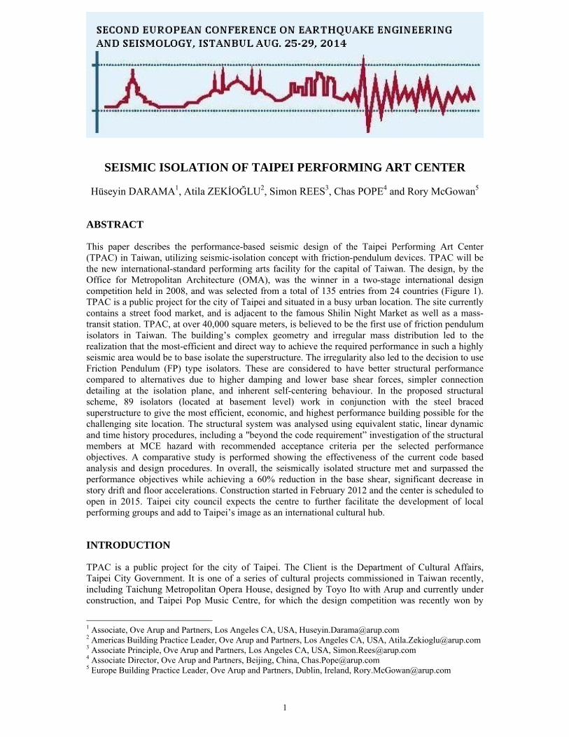
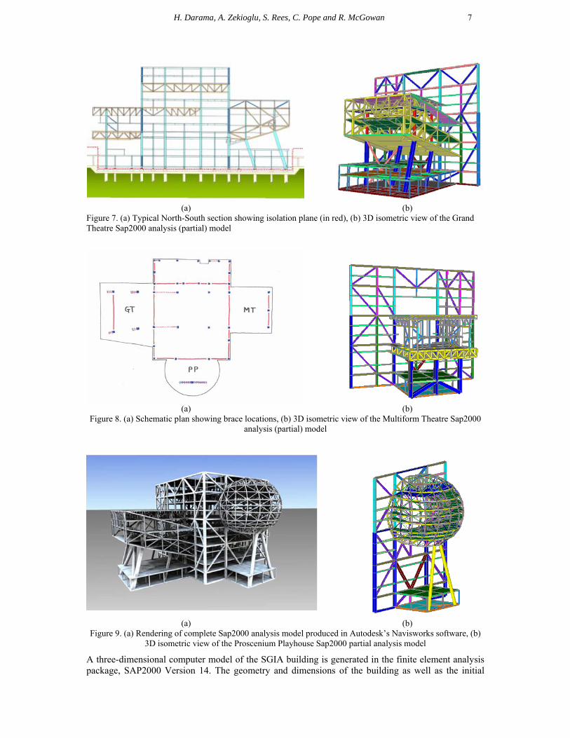
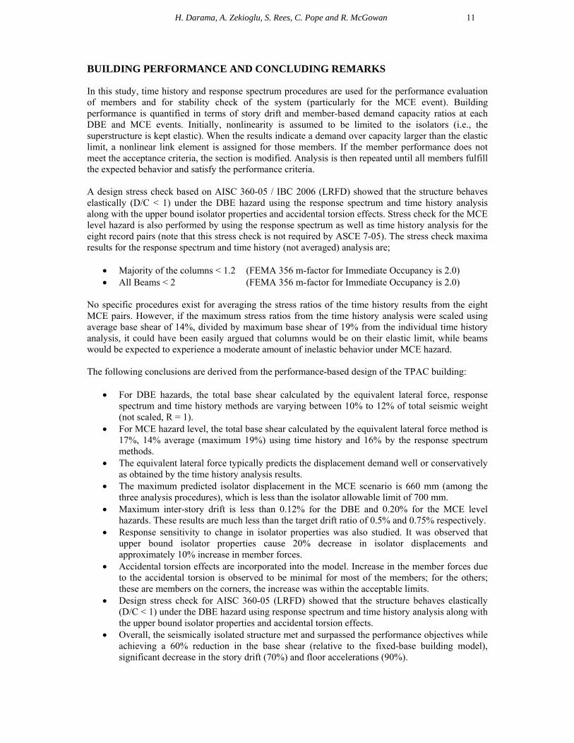
superstructure to give the most efficient, economic, and highest performance building possible for the challenging site location and conditions. The isolation plane extends around all superstructure columns, and is located at the basement level in order to avoid conflicts with the stage pits (see Figure 7 (a)). Superstructure and Gravity system: The superstructure is constructed in steel-braced frame with composite concrete /steel floors. Floors are generally normal weight concrete slabs, up to 175mm thick (200mm thick on diaphragm floors, where the bracing nodes out with the columns), supported on metal decking acting as permanent formwork. The slabs span between secondary composite steel beams at approximately 3m centres, which are in turn supported by primary beams or trusses depending on location. It is intended that the 3W type decking is used. Composite (concrete-filled box) columns will be used for primary columns, to reduce steel weight. Figure 8(a) shows the superstructure lateral stability concept. The red lines in Figure 8(a) indicate the locations of braced panels. These are mainly located around the perimeter of the Cube, providing a system with high lateral and torsional resistance. Further lateral stiffening is added to the columns supporting the auditoria, to mitigate the local torsional responses that would otherwise arise. Cube transfer structure: The Cube is 53.5 x 53.5m on plan within the main braced elevations, and is 55m in height. It contains twelve storeys, each typically 5m in height. The Cube contains the main stages and rear stages, lobbies, public circulation route, rehearsal rooms and other facilities. Due to the extensive column-free spaces for the stacked stages etc, only the columns located on the braced elevations plus four internal primary columns run the full height of the Cube. A significant number of trusses are therefore introduced. The trusses are generally one storey deep, and concentrated on two primary north-south and east-west structural lines at levels F3-F4, F6-F7 and F9-F10 to suit the architectural planning. Additional columns are introduced wherever possible to reduce floor structure depth and improve economy. The Cube contains many multi-storey spaces. Therefore, most storeys contain large floor voids whilst some storeys have minimal floor areas (e.g. balconies, walkways) which are typically supported from the storey above or below. Proscenium Playhouse (PP): The Proscenium Playhouse Auditorium is an ellipsoidal structure which projects 26m east from the Cube between levels F5 and F12. The primary structure of the PP is a steel three-dimensional space truss, supported by the Cube perimeter columns and an external inverted-V column (/\). A ring truss at the interface with the Cube allows gravity loads from all levels of the PP to be transferred from the space truss into the columns, and also carries the Cube’s lateral bracing around the auditorium void. The facetted shell structure provides a highly redundant structural system, which enables individual elements to be removed without compromising the integrity of the system. This is essential to allow the inner shell and intra-shell zones to be “eroded” to suit openings for balconies, circulation routes, ceiling lighting, etc. The 3D space truss is self-stable in three dimensions. Forces in the north-south direction are distributed between the east face of the Cube braced frame, and the /\-columns under the auditorium. Forces in the east-west direction are transferred from the space truss into primary beams within the Cube, and from there into the Cube braced frame via the slab diaphragms (see Figure 9(b)). Grand Theatre (GT): The Grand Theatre is 37m long and 39m wide at its tip. It projects south from the Cube between levels F3 and F8. Primary framing is provided by two full-height trusses running north-south on either side of the auditorium between the Cube and five sloping column supports. The main trusses are continuous with the internal Cube transfer trusses. Two levels of secondary cross trusses span east-west between the main trusses to support the raking auditorium and roof structure, and also support edge trusses which carry the access staircases (see Figure 7(b)). Multiform Theatre (MT): The Multiform Theatre is approximately 29m long and 31m wide. It projects north from the Cube between levels F3 and F7. Structurally, it is similar to the GT with east-west trusses carrying the floor and roof respectively, spanning on to primary north-south trusses at two levels. The main trusses are supported near their northern end by three external support columns (see Figure 8(b)).
H. Darama, A. Zekioglu, S. Rees, C. Pope and R. McGowan 7
(a) (b)
Figure 7. (a) Typical North-South section showing isolation plane (in red), (b) 3D isometric view of the Grand Theatre Sap2000 analysis (partial) model
(a) (b)
Figure 8. (a) Schematic plan showing brace locations, (b) 3D isometric view of the Multiform Theatre Sap2000 analysis (partial) model
(a) (b)
Figure 9. (a) Rendering of complete Sap2000 analysis model produced in Autodesk’s Navisworks software, (b) 3D isometric view of the Proscenium Playhouse Sap2000 partial analysis model
A three-dimensional computer model of the SGIA building is generated in the finite element analysis package, SAP2000 Version 14. The geometry and dimensions of the building as well as the initial

8
sizes of the structural elements are provided by the architect. SAP2000 was used both for the linear elastic analysis of the steel superstructure, as well as a non-linear time history analysis used for the isolator design. For this analysis, it was assumed – and verified – that the superstructure would remain elastic, allowing the analysis model to be simplified. Figure 9(a) shows the rendering image from the SAP2000 model produced in Autodesk’s Navisworks software.
ISOLATOR DESIGN
Even though base isolated buildings most resemble Single Degree of Freedom (SDOF) structures, U.S. building codes have stringent requirement on the use of base isolation and most often nonlinear response history analyses are required. During conceptual design or schematic design, it would be inefficient to carry out too many detailed analyses. Analysis on SDOF that incorporates different fundamental period of base isolation to evaluate maximum isolator displacement and base shear would be especially useful. The parametric study performed here is independent of isolator type and purely dependant on target isolated period and supplementary damping provided by the isolators. The summary of the results of the parametric study are given in Table 3. The table/data provided here facilitates a convenient determination of relative benefits of various isolation system/properties.
Table 3. Parametric comparison for the prediction of isolated response
FIXED BASE BASE ISOLATED 3 sec BASE ISOLATED 4 sec
DBE MCE DBE MCE DBE MCE DBE MCE DBE MCE
5% 5% 40% 30% 30% 20% 40% 30% 30% 20%
Period, T(sec.) 1.00 1.00 3.00 3.00 3.00 3.00 4.00 4.00 4.00 4.00
Base Shear (% W) 0.60 0.80 0.13 0.19 0.14 0.23 0.10 0.14 0.11 0.17
Isolator Disp., D (mm) - - 285 426 320 505 380 568 426 673
Figure 10. (a) Geometry of the proposed 4 second friction pendulum isolator for TPAC, (b) Physical model used
for prototype testing, (c) Nonlinear isolator backbone curve

H. Darama, A. Zekioglu, S. Rees, C. Pope and R. McGowan 9
By the parametric study, it has been understood that the most optimum/beneficial solution can be achieved using 4 second bearing (effective isolated period). For example, using 4 second isolator with 20% damping at MCE will result in a base shear of 0.17W and 673mm total isolator displacement (without accidental torsion). Friction Pendulum (FP) type isolator was selected for the project after performance-cost study. These are considered to have better structural performance compared to alternatives due to higher damping and lower base shear forces, simpler connection detailing at the isolation plane, and inherent self-centering behaviour. Geometry of the proposed FP bearing is shown in Figure 10(a). An idealized nonlinear shear-displacement curve for single-friction-pendulum isolators is shown at Figure 10(c). Three types of isolators are proposed according to the variation in vertical demand.
NONLINEAR RESPONSE HISTORY ANALYSIS
In the design of the TPAC building, nonlinear time-history procedure is used for the estimation of structural responses such as maximum isolator displacements and shears as well as for the structural member performance evaluation and stability check of the system for MCE hazard. In the linear procedures (equivalent lateral and response spectrum methods), effective stiffness (Keff) and damping (eff) are the only isolator parameter used in the analysis. In the case of nonlinear time-history analysis, a new set of parameters is necessary to realize the nonlinear hysteretic behaviour of the friction-pendulum devices. Herein, a Parallel Discrete Spring Model (PDSM), which has three types of nonlinear elements that are connected in parallel, is adopted for the nonlinear modelling of the FP isolator (Figure 11, Zekioglu et al).
Figure 11. (a) Sap2000 analysis model of TPAC, (b) Nonlinear parallel discrete spring model for FP isolators
Non-linear time history analysis was performed using eight pairs of records provided by local geotechnical consultant. Isolators are modelled using Friction Isolator element capable of real uplift (zero tension stiffness). For each record, 2 cases were generated. The first case is where the records are applied directly in their natural direction, i.e. E-W record applied in the X-direction and N-S record is applied in the Y-direction. The second case is where the records are applied in the reverse orthogonal direction, i.e. E-W record applied in the Y-direction and N-S record applied in the X-direction. Direct Integration method was used for NLTH using SAP2000 software. Unlike Response Spectrum procedure, the hysteretic energy (damping) dissipated by the isolators is automatically taken into account by the nonlinear model assigned to the isolators. It is also worth mentioning that 2% inherent-equivalent-viscous-damping is specified to account for energy dissipation by the connectors of partitions and wave radiation by the foundation system. In order to verify the nonlinear properties of isolators that are assumed in the modelling, the target envelope and hysteresis loops are plotted together (Figure 12(a)). The graph shows that the simulation and target curve are in close correlation. Figure 12(b) shows a typical orbital plot of an isolator obtained from NLTH analysis. This is important for checking if isolators’ resultant displacements are within their capacity (outer ring).

10
(a) (b)
Figure 12. Results from NLTH analysis for the verification of hysteresis model (a) Force–Displacement response of Link #107 (921Tap08), and (b) Isolator Orbit path
The summary of the results from Nonlinear Time History (NLTH) procedure in the principle directions are shown in Table 4. Although time history results based on the ensemble average of the analysis records are in good correlation with the response spectrum, there is significant deviation between the minimum and maximum envelopes (Figure 13). The predicted mean isolator displacement at MCE is 660mm which is less than the isolator capacity of 700 mm.
Table 4. Summary of the results from nonlinear time history procedure
Design Based Earthquake
(DBE) Maximum Considered Earthquake
(MCE)
Mean, EW/NS Max., EW/NS Mean, EW/NS Max., EW/NS
Isolator Displacement with 395/406 612/618 638/660 976/998
Accidental torsion, (mm)
Isolator Displacement without 330/337 511/516 529/532 810/814
Accidental torsion, (mm)
Base Shear Ratio Lateral Force/Seismic Weight
0.10 0.13 0.14 0.19
Figure 13. NLTH results: (a) Maximum building displacements, (b) Maximum Story Shear Coefficients
H. Darama, A. Zekioglu, S. Rees, C. Pope and R. McGowan 11
BUILDING PERFORMANCE AND CONCLUDING REMARKS
In this study, time history and response spectrum procedures are used for the performance evaluation of members and for stability check of the system (particularly for the MCE event). Building performance is quantified in terms of story drift and member-based demand capacity ratios at each DBE and MCE events. Initially, nonlinearity is assumed to be limited to the isolators (i.e., the superstructure is kept elastic). When the results indicate a demand over capacity larger than the elastic limit, a nonlinear link element is assigned for those members. If the member performance does not meet the acceptance criteria, the section is modified. Analysis is then repeated until all members fulfill the expected behavior and satisfy the performance criteria. A design stress check based on AISC 360-05 / IBC 2006 (LRFD) showed that the structure behaves elastically (D/C < 1) under the DBE hazard using the response spectrum and time history analysis along with the upper bound isolator properties and accidental torsion effects. Stress check for the MCE level hazard is also performed by using the response spectrum as well as time history analysis for the eight record pairs (note that this stress check is not required by ASCE 7-05). The stress check maxima results for the response spectrum and time history (not averaged) analysis are;
Majority of the columns < 1.2 (FEMA 356 m-factor for Immediate Occupancy is 2.0) All Beams < 2 (FEMA 356 m-factor for Immediate Occupancy is 2.0)
No specific procedures exist for averaging the stress ratios of the time history results from the eight MCE pairs. However, if the maximum stress ratios from the time history analysis were scaled using average base shear of 14%, divided by maximum base shear of 19% from the individual time history analysis, it could have been easily argued that columns would be on their elastic limit, while beams would be expected to experience a moderate amount of inelastic behavior under MCE hazard. The following conclusions are derived from the performance-based design of the TPAC building:
For DBE hazards, the total base shear calculated by the equivalent lateral force, response spectrum and time history methods are varying between 10% to 12% of total seismic weight (not scaled, R = 1).
For MCE hazard level, the total base shear calculated by the equivalent lateral force method is 17%, 14% average (maximum 19%) using time history and 16% by the response spectrum methods.
The equivalent lateral force typically predicts the displacement demand well or conservatively as obtained by the time history analysis results.
The maximum predicted isolator displacement in the MCE scenario is 660 mm (among the three analysis procedures), which is less than the isolator allowable limit of 700 mm.
Maximum inter-story drift is less than 0.12% for the DBE and 0.20% for the MCE level hazards. These results are much less than the target drift ratio of 0.5% and 0.75% respectively.
Response sensitivity to change in isolator properties was also studied. It was observed that upper bound isolator properties cause 20% decrease in isolator displacements and approximately 10% increase in member forces.
Accidental torsion effects are incorporated into the model. Increase in the member forces due to the accidental torsion is observed to be minimal for most of the members; for the others; these are members on the corners, the increase was within the acceptable limits.
Design stress check for AISC 360-05 (LRFD) showed that the structure behaves elastically (D/C < 1) under the DBE hazard using response spectrum and time history analysis along with the upper bound isolator properties and accidental torsion effects.
Overall, the seismically isolated structure met and surpassed the performance objectives while achieving a 60% reduction in the base shear (relative to the fixed-base building model), significant decrease in the story drift (70%) and floor accelerations (90%).

12
TPAC is now under construction (Figure 14). Construction started in February 2012 and the center is scheduled to open in 2015. Taipei city council expects the centre to further facilitate the development of local performing groups and add to Taipei’s image as an international cultural hub.
Figure 14. Construction photo taken at the TPAC site in March 2014 (by OMA)
REFERENCES
ASCE, 2005, Minimum Design Loads for Buildings and Other Structures (ASCE 7-05), American Society of Civil Engineers, Reston, Virginia.
ASCE, 2006, Seismic Rehabilitation of Existing Buildings (ASCE 41-06), American Society of Civil Engineers, Reston, Virginia.
Chai J.F., Teng T.J., and Tsai K.J., 2009, “Development of Seismic Force Requirements for Buildings in Taiwan”, International Conference in Commemoration of the 10th Anniversary of the 1999 Chi-Chi Earthquake Taiwan.
CPA, 2005, Seismic Design Code and Commentary for Buildings, Construction and Planning Agency – Ministry of Internal Affair, Chinese Taipei (in Chinese)
Darama H. and Zekioğlu A. (2013) “Implementation of Seismic Isolation in Turkey for Continued Functionality”, 13th World Conference on Seismic Isolation, Sendai, Japan, 24-27 September
Fenz, D.M., and Constantinou, M.C., 2008b, “Mechanical behavior of Multi-Spherical Sliding Bearings, Report No. MCEER-08-0007,” Multidisciplinary Center for Earthquake Engineering Research, Buffalo, New York.
Loh C.H., Lee Z.K. et al, 2000, “Ground motion characteristics of the Chi-Chi Earthquake of 21 September 1999”, Earthquake Engineering & Structural Dynamics, Vol. 29, Issue 6, p867-897, June
Utsu, T., 1961, “A statistical study on the occurrence of aftershocks”, Geophysics Magazine, Vol. 30, p 521-605 Zekioğlu A., Darama H., Rees S., Pope C. and McGowan R. (2011) “Performance Based Seismic Design of
Base Isolated Taipei Performing Art Centre”, Convention of Structural Engineers Association of California (SEAOC), Las Vegas NV, 21-24 September
Zekioğlu A., Darama H., and Karahasanoglu S., 2010, “Seismic Sophistication”, ASCE Civil Engineering Magazine, Vol. 80, No:5, p64-69, May issue
Zekioğlu A., Darama H., and Erkus B., 2010, “Design Considerations for a base isolated structure with triple-friction-pendulum isolators: Istanbul Sabiha Gökçen International Airport Terminal Building", 9th U.S. National and 10th Canadian Conference on Earthquake Engineering, Paper #445, Ontario, Canada
Zekioğlu A., Darama H., and Erkus B., 2009, “Performance Based Seismic Design of a Large Seismically Isolated Structure: Istanbul Sabiha Gökçen International Airport Terminal Building”, Convention of Structural Engineers Association of California (SEAOC), p409-427, San Diego,CA
Wolff, E. D., and Constantinou M. C., 2004, “Experimental Study of Seismic Isolation Systems with Emphasis on Secondary System Response and Verification of Accuracy of Dynamic Response History Analysis Methods, Report No. MCEER-04-0001,” Multidisciplinary Center for Earthquake Engineering Research, Buffalo, New York.