Seismic Evaluation and Retrofit of Existing Reinforced Concrete Structures · Seismic Evaluation...
31
Wassim M. Ghannoum University of Texas at Austin Seismic Evaluation and Retrofit of Existing Reinforced Concrete Structures ACTS Conference, June 2014 Dbayyeh, Lebanon
Transcript of Seismic Evaluation and Retrofit of Existing Reinforced Concrete Structures · Seismic Evaluation...
Wassim M. Ghannoum University of Texas at Austin
Seismic Evaluation and Retrofit of Existing
Reinforced Concrete Structures
ACTS Conference, June 2014
Dbayyeh, Lebanon

Outline
1. Seismic Evaluation and Retrofit
Hazard
Evolution of standards
Process in the U.S.
2. The Future of Seismic Evaluations and Retrofit in
the U.S.
Memorandum of understanding between ASCE and
ACI
Updates to concrete provisions

Hazard
1. Seismic design codes introduced in the 80’s
2. Most construction prior to that period did not have
adequate strength or detailing
3. Just after that period, design forces were relatively
low and system-level vulnerability not adequately
addressed
4. A large body of nonductile building stock is
present around the world

Hazard
1. Nonductile concrete buildings are the single
largest threat to life in urban areas
2. In California alone nonductile concrete
buildings number over 20,000
Hazard
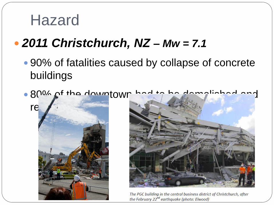
2011 Christchurch, NZ – Mw = 7.1
90% of fatalities caused by collapse of concrete
buildings
80% of the downtown had to be demolished and
rebuilt

Hazard
Wenchuan, China (2008) – Mw = 7.9
70,000 fatalities
Main source of deaths: concrete and masonry
construction

Hazard
Kocaeli, Turkey (1999) – Mw = 7.4
Deaths: 17,225, Injuries: 44,000
77,300 homes and 245,000 businesses destroyed

Seismic Evaluation and Retrofit in the
U.S.
Tools for Existing
Buildings • 0.75*1976 UBC
• ATC 3-06 (1978)
• ATC 14 (1987)
• FEMA 178 310 ASCE
31-03
Rapid evaluation of existing
buildings
• FEMA 273 356 ASCE
41-06
Advanced evaluation and
rehabilitation of existing
buildings

Seismic Evaluation and Retrofit in the
U.S.
ASCE 31 is a Standard for rapid seismic
evaluation of buildings
ASCE 41 is a Standard for detailed seismic
evaluation and retrofit of existing buildings
Widely adopted in the U.S. and worldwide

Seismic Evaluation and Retrofit in the
U.S.
ASCE 41-13
ASCE 31-
03
ASCE 41-
06
Seismic Evaluation and Retrofit of Existing Buildings

ASCE 41-13 Chapter 1 General Requirements
Chapter 2 Seismic Performance Objectives and Ground
Motions
Chapter 3 Evaluation and Retrofit Requirements
Chapter 4 Tier 1 Screening
Chapter 5 Tier 2 Deficiency-Based Evaluation and Retrofit
Chapter 6 Tier 3 Systematic Evaluation and Retrofit
Chapter 7 Analysis Procedures and Acceptance Criteria
Chapter 8 Foundations and Geologic Site Hazards
Chapter 9 Steel
Chapter 10 Concrete
Chapter 11 Masonry
Chapter 12 Wood and Cold-Formed Steel
Chapter 13 Architectural, Mechanical, and Electrical
Components
Chapter 14 Seismic Isolation and Energy Dissipation
Chapter 15 System-Specific Performance Procedures
Chapter 16 Tier 1 Checklists
Appendix A Guidelines for Deficiency-Based Procedures
Appendix B Use of ASCE 41-13 within Mitigation Programs
ASCE 31
ASCE 31

ASCE/SEI 41-13 - Tier 3 Process
1. Evaluate seismic hazard
A small break is given for existing buildings
2. Determine desired performance objectives
3. Analyze structure under hazard using Modeling
Parameters
linear/nonlinear, dynamic/static
4. Ensure member and structural demands do not
exceed Acceptance Criteria

Operational
Immediate
Occupancy
Life
Safety
Collapse
Prevention
50% / 50 yr
(72 year)
20% / 50 yr
(225 year)
BSE-1
(~475 year)
BSE-2
(~2475 yr)
Building Performance Level E
art
hq
uak
e H
aza
rd L
evel
Seismic Evaluation and Retrofit in the
U.S.

Q/Qy
1.0
A
B C
D E (Peak deformation)
θy θ or D
a
b a, b & c: Modeling Parameters
c
IO, LS & CP: Acceptance Criteria IO: Immediate Occupancy
LS: Life Safety
CP: Collapse Prevention
IO
LS CP
ASCE/SEI 41-13 Generic Backbone Curve
MP or AC

Future of Seismic Evaluations and Retrofit in the U.S.
ASCE 41 is in need of updating
Document is over 1000 pages long
Covers most material types
Committee has fewer than 30 voting members
Agreement between ACI and ASCE signed in 2014

Future of Seismic Evaluations and Retrofit in the U.S.
ACI committee 369, “Seismic Repair and
Rehabilitation” starting a new Standard
ACI 369 Standard will be the source
document for concrete provisions of ASCE
41
Agreement is a foundation for material
specialty organizations and ASCE to work
together

ACI 369 Standard Seismic Evaluation and Retrofit of Existing Concrete Buildings Chapter 1 Scope
Chapter 2 Material Properties and Condition
Assessment
Chapter 3 General Assumptions and
Requirements
Chapter 4 Concrete Moment Frames
Chapter 5 Precast Concrete Frames
Chapter 6 Concrete Frames with Masonry Infills
Chapter 7 Concrete Shear Walls
Chapter 8 Precast Concrete Shear Walls
Chapter 9 Concrete Braced Frames
Chapter 10 Cast-in-Place Concrete Diaphragms
Chapter 11 Precast Concrete Diaphragms
Chapter 12 Concrete Foundations

1. New MP for concrete columns
Current MP defined inconsistently across document
2. Use new extended database with close to 500
column tests
3. Treat circular columns
4. Adjust AC based on new MP
Conservatism should be incorporated in AC not MP
Select AC at percentiles of MP to achieve consistent
probabilities of exceedance across all members
ACI 369 Standard MP and AC for RC columns

MP for RC columns - Dataset Extended database with close to 500 column tests
Ghannoum, W. M., and Sivaramakrishnan, B. (2012). "ACI 369 Rectangular Column Database.“ DOI: 10.4231/D36688J50
Ghannoum, W. M., and Sivaramakrishnan, B. (2012). "ACI 369 Circular Column Database.“ DOI:10.4231/D39Z90B9T
https://nees.org/resources/3658 ; https://nees.org/resources/3659

MP for RC columns - Dataset Extended database with close to 500 column tests
0 0.1 0.2 0.3 0.4 0.5 0.6 0.7 0.8 0.9 10
10
20
30
40
50
60
70
80
90
Axial Load Ratio
Nu
mb
er
of C
olu
mn
s
Rectangular
Circular
0 0.25 0.5 0.75 1 1.25 1.5 1.750
20
40
60
80
100
120
140
s/d
Nu
mb
er
of C
olu
mn
s
Rectangular
Circular
0 0.0025 0.005 0.0075 0.01 0.0125 0.015 0.0175 0.02 0.0225 0.025 0.0275 0.03 0.0325 0.0350
10
20
30
40
50
60
70
80
90
Transverse Reinforcement Ratio
Nu
mb
er
of C
olu
mn
s
Rectangular
Circular
0 0.2 0.4 0.6 0.8 1 1.2 1.4 1.6 1.8 20
10
20
30
40
50
60
70
80
90
Vy/V
o
Num
ber
of C
olu
mns
Rectangular
Circular
V
Drift
Vy
Vy>Vo
Vy<Vo

MP for RC columns - Dataset
Data in form of lateral force-deformation plots
Buenrostro, E. (2013). “Deformations in Non-Seismically Detailed
Concrete Columns." MS Report, University of Texas at Austin

MP for RC columns –
Parameters
Most influential parameters for a were found to be
Axial load ratio
Transverse reinforcement ratio
Vy/Vo

Parameters
Table bounds need updating
0 0.1 0.2 0.3 0.4 0.5 0.6 0.7 0.80
0.005
0.01
0.015
0.02
0.025
0.03
0.035
Axial Load Ratio
tra
nsve
rse
Re
info
rce
me
nt R
atio
Circular columns
Rectangular columns
Table 10-8. Modeling Parameters and Numerical Acceptance Criteria for Nonlinear Procedures—Reinforced Concrete Columns
Conditions
Modeling Parametersa Acceptance Criteriaa
Plastic Rotations
Angle (radians)
Residual
Strength
Ratio
Plastic Rotations Angle
(radians)
Performance Level
IO
a b c LS CP
Condition i.b c
0.1 0.006 0.035 0.060 0.2 0.005 0.045 0.060
0.6 0.006 0.010 0.010 0.0 0.003 0.009 0.010
0.1 0.002 0.027 0.034 0.2 0.005 0.027 0.034
0.6 0.002 0.005 0.005 0.0 0.002 0.004 0.005
Condition ii.b
c
d
0.1 0.006 3 (0.25) 0.032 0.060 0.2 0.005 0.045 0.060
0.1 0.006 6 (0.5) 0.025 0.060 0.2 0.005 0.045 0.060
0.6 0.006 3 (0.25) 0.010 0.010 0.0 0.003 0.009 0.010
0.6 0.006 6 (0.5) 0.008 0.008 0.0 0.003 0.007 0.008
0.1 0.0005 3 (0.25) 0.012 0.012 0.2 0.005 0.010 0.012
0.1 0.0005 6 (0.5) 0.006 0.006 0.2 0.004 0.005 0.006
0.6 0.0005 3 (0.25) 0.004 0.004 0.0 0.002 0.003 0.004
0.6 0.0005 6 (0.5) 0.0 0.0 0.0 0.0 0.0 0.0
Condition iii.b c
0.1 0.006 0.0 0.060 0.0 0.0 0.045 0.060
0.6 0.006 0.0 0.008 0.0 0.0 0.007 0.008
0.1 0.0005 0.0 0.006 0.0 0.0 0.005 0.006
0.6 0.0005 0.0 0.0 0.0 0.0 0.0 0.0
Condition iv. Columns controlled by inadequate development or splicing along the clear heightb c
0.1 0.006 0.0 0.060 0.4 0.0 0.045 0.060
0.6 0.006 0.0 0.008 0.4 0.0 0.007 0.008
0.1 0.0005 0.0 0.006 0.2 0.0 0.005 0.006
0.6 0.0005 0.0 0.0 0.0 0.0 0.0 0.0
P
Ag fc-----------
Av
bws--------=
P
Ag fc-----------
Av
bws--------=
V
bwd fc-------------------
P
Ag fc-----------
Av
bws--------=
P
Ag fc-----------
Av
bws--------=

MP for RC columns – a Regression analysis results
0.0023.063.0043.0042.0'
o
y
t
cg
RV
V
fA
Pa (rad)
Rectangular columns
Circular columns (spirals or hoops)
0.0037.03.1058.006.0'
o
y
t
cg
CV
V
fA
Pa (rad)
0.0005 ≤ ρt ≤
0.0175
Vy/Vo ≥ 0.2
P/(Agf’c) ρt Vy/Vo aR (rad) aC (rad)
0 0.0005 0.2 0.038 0.058
0 0.0005 2.0 0.0 0.0
0 0.0175 0.2 0.048* 0.071*
0 0.0175 2.0 0.007 0.0
0.7 0.0005 0.2 0.008 0.016
0.7 0.0005 2.0 0.0 0.0
0.7 0.0175 0.2 0.018 0.029
0.7 0.0175 2.0 0.0 0.0
Values of a at parameter boundaries

MP for RC columns – a Analysis of fit
-0.04 -0.02 0 0.02 0.04 0.06 0.080
0.1
0.2
0.3
0.4
0.5
0.6
0.7
0.8
0.9
1
Error in aR
= Experiment - Estimate (rad)
Cu
mu
lative
Dis
trib
utio
n
Number of Tests = 319
Standard Deviation Equation = 0.015
Standard Deviation ASCE41-06 = 0.015
Equation estimates
ASCE 41-06 estimates
-0.04 -0.02 0 0.02 0.04 0.06 0.080
0.1
0.2
0.3
0.4
0.5
0.6
0.7
0.8
0.9
1
Error in aC
= Experiment - Estimate (rad)
Cu
mu
lative
Dis
trib
utio
n
Number of Tests = 171
Standard Deviation Equation = 0.019
Standard Deviation ASCE41-06 = 0.022
Equation estimates
ASCE 41-06 estimates
• Median estimate achieved
• Improved fit for circular columns

MP for RC columns – a Analysis of fit
0 0.2 0.4 0.6 0.8 1 1.2 1.4-0.04
-0.02
0
0.02
0.04
0.06
0.08
Rectangular column s/d
Err
or
in a
R =
Experim
ent -
Estim
ate
(ra
d)
135o hooks
90o hooks
Unknown
0 0.2 0.4 0.6 0.8 1 1.2 1.4-0.04
-0.02
0
0.02
0.04
0.06
0.08
Circular column s/d
Err
or
in a
C =
Experim
ent -
Estim
ate
(ra
d)
spirals
lapped
Unknown
• Little bias with respect to s/d
• Little bias with respect to tie hooks

MP for RC columns – b Behavioral model
Due to the scarcity of columns tested to axial collapse a
behavioral-model is selected instead of a regression-
based model
Drift ratio at axial failure
Simplified Elwood-Moehle axial failure model
∆
𝐿=
0.5
5 +𝑃
𝐴𝑣𝑓𝑦𝑡
𝑠𝑑𝑐

MP for RC columns – b Analysis of fit
• Including a loading protocol
factor of 0.5 on the drift at
axial failure for columns
tested under 6 load cycle
per drift level or bi-axially
Model Average
Measured/
Calculated drift
ratio at axial
failure
Standard
Deviation
Coefficient of
Variation
ASCE 41-06 Suppl. 1 1.97 0.93 0.47
Elwood-Moehle 0.97 0.44 0.46
Simplified Elwood –
Moehle with loading
factor
1.13 0.38 0.33

MP for RC columns – b Analysis of fit
Using full database
0 0.02 0.04 0.06 0.08 0.1 0.12 0.140
0.02
0.04
0.06
0.08
0.1
0.12
0.14
Experimental b2R
(rad)
Pro
posed b
ehavio
ral m
odel b (
rad)
Tests not to axial collapse
Tests to axial collapse
0 0.02 0.04 0.06 0.08 0.1 0.12 0.140
0.02
0.04
0.06
0.08
0.1
0.12
0.14
Experimental b2C
(rad)
Pro
posed b
ehavio
ral m
odel b (
rad)
Tests not to axial collapse
Tests to axial collapse
• Model produces median estimates for rect. and circular columns tested
to collapse

Acceptance Criteria
AC defined as percentiles of MP a and b
Fixed probability of exceeding a threshold behavior
defined by MP a and b
IO LS Primary CP Primary
LS
Secondary
CP Secondary
Criteria 10% of
MP a
20th percentile
of MP a
35th percentile
of MP a
10th percentile
of MP b
25th percentile of
MP b
Rectangula
r
0.1
aR
0.50 aR 0.75 aR 0.60 bR 0.75 bR
Circular 0.1
aC
0.30 aC 0.65 aC 0.60 bC 0.75 bC

Summary
1. Seismic hazard in the Middle-East is high and
mitigation is needed
2. ASCE 41-13 is the standard used in the U.S. for
seismic evaluation and retrofit of buildings
3. Document used in many other applications as it
contains MP and AC for a wide range of members and
materials
4. ACI 369 standard will be the source document the
concrete provisions of ASCE 41.
5. Wide ranging updates to concrete provisions are under
way
6. Discussions on altering procedures in ASCE 41 also
under way