Seismic Design and Retrofit
23
January 2015 – v 2.0
Transcript of Seismic Design and Retrofit
January 2015 – v 2.0

Page intentionally left blank.
Contents
NHDOT Bridge Design Manual v2.0 Page viii
January 2015
Chapter 5 Seismic Design and Retrofit 5.1 Design Criteria 5.1-1 5.1.1 Design Approach and Considerations 5.1-1 5.1.2 Bridge Classification and Performance Objectives 5.1-1 5.2 Seismic Analysis and Design Procedure 5.2-1 5.2.1 Peak Ground Acceleration Coefficient (PGA) 5.2-1 5.2.2 Short-Term Spectral Acceleration Coefficient (SS) 5.2-1 5.2.3 Long-Term Spectral Acceleration Coefficient (S1) 5.2-2 5.2.4 Site Classifications 5.2-2 5.2.5 Site Factors 5.2-2 5.2.6 Design Response Spectrum 5.2-3 5.2.7 Seismic Performance Zones 5.2-3 5.2.8 Calculation of Design Forces 5.2-4 5.2.9 Minimum Support Length Requirements 5.2-4 5.2.10 Forces Transferred from Superstructure to Substructure 5.2-4 5.3 Rehabilitation of Existing Bridges 5.3-1 5.3.1 General 5.3-1 5.4 Seismic Isolation Bearings 5.4-1 5.4.1 General 5.4-1 5.5 Seismic Design Requirements for Retaining Walls 5.5-1 5.5.1 General 5.5-1
References 5.R-1
Appendix A Appendix 5.1-A1 AASHTO Seismic Design Flowchart 5.1-A1-1

Page intentionally left blank.
Chapter 5 Seismic Design and Retrofit
Chapter 5 Seismic Design and Retrofit
5.1 Design Criteria
Seismic design of new bridges and bridge widenings shall conform to AASHTO 3.10 and AASHTO Guide Specifications for LRFD Seismic Bridge Design. Analysis and design of seismic retrofits for existing bridges shall be completed in accordance with Section 5.3 of this chapter. For nonconventional bridges, bridges that are deemed critical or essential, or bridges that fall outside the scope of the AASHTO LRFD Specifications for any other reason, project-specific design requirements shall be developed and submitted to the Bridge Design Chief for approval.
5.1.1 Design Approach and Considerations
The Department’s primary objective when designing bridges to resist earthquake loading is to minimize damage and prevent the loss of span or collapse of a structure. The AASHTO seismic design requirements are not intended to eliminate all damage.
The primary objective in seismic design is to prevent foundation failure, liquefaction failure, support failure at the bearings and expansion joints within a span, shear or moment failure of the columns, and failure of the connecting components. Based on the bridge classification and the performance objectives, it is the Department’s policy to permit designs with inelastic deformation that is ductile. Damage is permitted, provided it is at locations that can be readily inspected and repaired after the seismic event. Plastic hinging in superstructure components (which may impact the gravity load support capabilities of the structure) or bearing systems not capable of providing the expected seismic displacement and forces is not permitted.
All bridge components and their foundation systems must provide the means of adequately dissipating energy or must be capable of sufficiently resisting seismically induced structure component displacements. The systems must provide for uninterrupted load paths for transmitting seismically induced forces into the ground.
Some basic seismic design concepts that will improve seismic performance by enhancing the load distribution to the substructures are: continuity of the superstructure, symmetry in structure stiffness and geometry, and overall structure redundancy. These design concepts not only benefit the seismic performance but also the overall performance of the structure.
See Appendix 5.1-A1 for AASHTO’s seismic design flowchart.
5.1.2 Bridge Classification and Performance Objectives
A. “Regular” and “Irregular” Bridges
The definitions of “regular” and “irregular” bridges for seismic design are given in AASHTO Table 4.7.4.3.1-2. Generally, bridges are regular if there are 2 to 6 spans (single span bridges are always regular), do not have span length ratios that are significantly large, do not have pier stiffness ratios that are significantly large, and are not overly curved. Multi-span bridges defined as “regular or “irregular” shall be designed for analysis requirements noted in AASHTO 4.7.4.3.
NHDOT Bridge Design Manual v2.0 Page 5.1-1 January 2015

Chapter 5 Seismic Design and Retrofit
B. Operational Classification
The definitions of operational categories, “Critical, Essential or Other” for seismic design are given in AASHTO 3.10.5. The Department will classify all bridges on a case-by-case basis.
Most bridges on the State System and many on the Municipal System should be classified as “Essential”. Some Municipal bridges may be classified as “Other”. Major bridges fitting the classifications of either “Critical” or “Essential” will be so designated by the Chief of Bridge Design.
NHDOT Bridge Design Manual v2.0 Page 5.1-2 January 2015

Chapter 5 Seismic Design and Retrofit
5.2 Seismic Analysis and Design Procedure
The bridge classifications described in Section 5.1.2, in conjunction with the site classifications as described in Section 5.2.4, form the basis for the selection of the seismic analysis, design, and detailing procedures. These procedures outline the specific requirements for analysis and design reflecting the variation in seismic risk.
5.2.1 Peak Ground Acceleration Coefficient (PGA)
In accordance with AASHTO Figure 3.10.2.1-1, the peak ground acceleration coefficient for New Hampshire varies on the map from 6.3% - 11%.
5.2.2 Short-Term Spectral Acceleration Coefficient (SS)
In accordance with AASHTO Figure 3.10.2.1-2, the short-term spectral acceleration coefficient for New Hampshire varies on the map from 14% - 21%.
AASHTO Peak Ground Acceleration Coefficient (PGA) Map
Figure 5.2.1-1
AASHTO Short-Term Spectral Acceleration Coefficient (SS) Map
Figure 5.2.2-1
NHDOT Bridge Design Manual v2.0 Page 5.2-1 January 2015
Chapter 5 Seismic Design and Retrofit
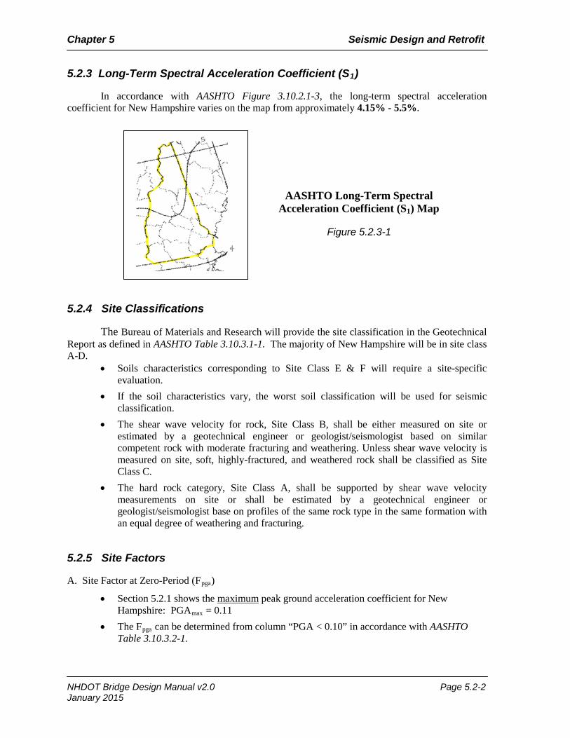
5.2.3 Long-Term Spectral Acceleration Coefficient (S1)
In accordance with AASHTO Figure 3.10.2.1-3, the long-term spectral acceleration coefficient for New Hampshire varies on the map from approximately 4.15% - 5.5%.
5.2.4 Site Classifications
The Bureau of Materials and Research will provide the site classification in the Geotechnical Report as defined in AASHTO Table 3.10.3.1-1. The majority of New Hampshire will be in site class A-D.
• Soils characteristics corresponding to Site Class E & F will require a site-specific evaluation.
• If the soil characteristics vary, the worst soil classification will be used for seismic classification.
• The shear wave velocity for rock, Site Class B, shall be either measured on site or estimated by a geotechnical engineer or geologist/seismologist based on similar competent rock with moderate fracturing and weathering. Unless shear wave velocity is measured on site, soft, highly-fractured, and weathered rock shall be classified as Site Class C.
• The hard rock category, Site Class A, shall be supported by shear wave velocity measurements on site or shall be estimated by a geotechnical engineer or geologist/seismologist base on profiles of the same rock type in the same formation with an equal degree of weathering and fracturing.
5.2.5 Site Factors
A. Site Factor at Zero-Period (Fpga)
• Section 5.2.1 shows the maximum peak ground acceleration coefficient for New Hampshire: PGAmax = 0.11
• The Fpga can be determined from column “PGA < 0.10” in accordance with AASHTO Table 3.10.3.2-1.
AASHTO Long-Term Spectral Acceleration Coefficient (S1) Map
Figure 5.2.3-1
NHDOT Bridge Design Manual v2.0 Page 5.2-2 January 2015
Chapter 5 Seismic Design and Retrofit
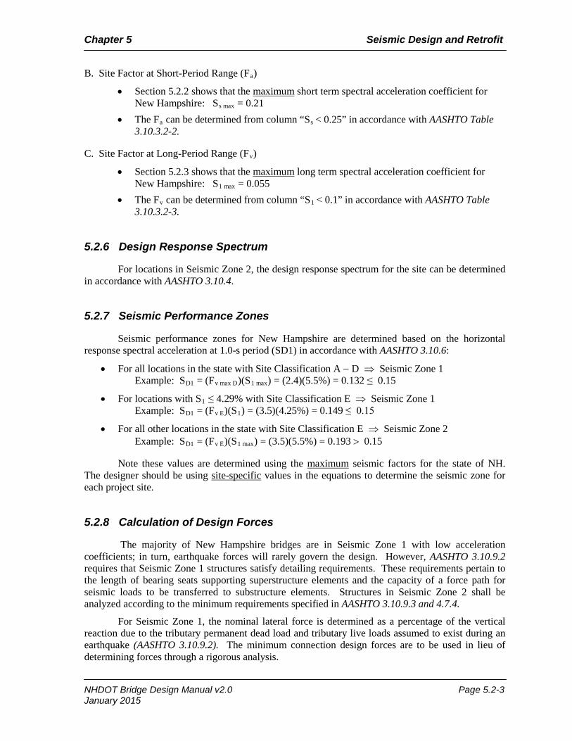
B. Site Factor at Short-Period Range (Fa)
• Section 5.2.2 shows that the maximum short term spectral acceleration coefficient for New Hampshire: Ss max = 0.21
• The Fa can be determined from column “Ss < 0.25” in accordance with AASHTO Table 3.10.3.2-2.
C. Site Factor at Long-Period Range (Fv)
• Section 5.2.3 shows that the maximum long term spectral acceleration coefficient for New Hampshire: S1 max = 0.055
• The Fv can be determined from column “S1 < 0.1” in accordance with AASHTO Table 3.10.3.2-3.
5.2.6 Design Response Spectrum
For locations in Seismic Zone 2, the design response spectrum for the site can be determined in accordance with AASHTO 3.10.4.
5.2.7 Seismic Performance Zones
Seismic performance zones for New Hampshire are determined based on the horizontal response spectral acceleration at 1.0-s period (SD1) in accordance with AASHTO 3.10.6:
• For all locations in the state with Site Classification A − D ⇒ Seismic Zone 1 Example: SD1 = (Fv max D)(S1 max) = (2.4)(5.5%) = 0.132 ≤ 0.15
• For locations with S1 ≤ 4.29% with Site Classification E ⇒ Seismic Zone 1 Example: SD1 = (Fv E)(S1) = (3.5)(4.25%) = 0.149 ≤ 0.15
• For all other locations in the state with Site Classification E ⇒ Seismic Zone 2 Example: SD1 = (Fv E)(S1 max) = (3.5)(5.5%) = 0.193 > 0.15
Note these values are determined using the maximum seismic factors for the state of NH. The designer should be using site-specific values in the equations to determine the seismic zone for each project site.
5.2.8 Calculation of Design Forces
The majority of New Hampshire bridges are in Seismic Zone 1 with low acceleration coefficients; in turn, earthquake forces will rarely govern the design. However, AASHTO 3.10.9.2 requires that Seismic Zone 1 structures satisfy detailing requirements. These requirements pertain to the length of bearing seats supporting superstructure elements and the capacity of a force path for seismic loads to be transferred to substructure elements. Structures in Seismic Zone 2 shall be analyzed according to the minimum requirements specified in AASHTO 3.10.9.3 and 4.7.4.
For Seismic Zone 1, the nominal lateral force is determined as a percentage of the vertical reaction due to the tributary permanent dead load and tributary live loads assumed to exist during an earthquake (AASHTO 3.10.9.2). The minimum connection design forces are to be used in lieu of determining forces through a rigorous analysis.
NHDOT Bridge Design Manual v2.0 Page 5.2-3 January 2015
Chapter 5 Seismic Design and Retrofit
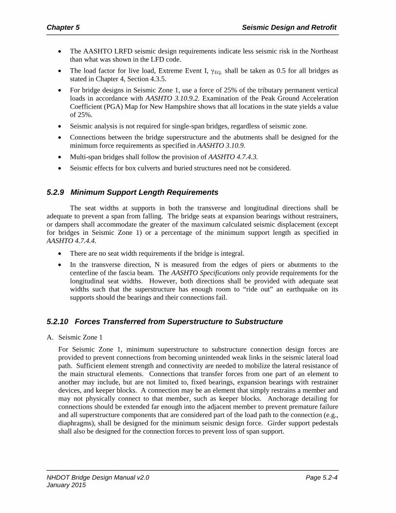
• The AASHTO LRFD seismic design requirements indicate less seismic risk in the Northeast than what was shown in the LFD code.
• The load factor for live load, Extreme Event I, γEQ, shall be taken as 0.5 for all bridges as stated in Chapter 4, Section 4.3.5.
• For bridge designs in Seismic Zone 1, use a force of 25% of the tributary permanent vertical loads in accordance with AASHTO 3.10.9.2. Examination of the Peak Ground Acceleration Coefficient (PGA) Map for New Hampshire shows that all locations in the state yields a value of 25%.
• Seismic analysis is not required for single-span bridges, regardless of seismic zone. • Connections between the bridge superstructure and the abutments shall be designed for the
minimum force requirements as specified in AASHTO 3.10.9. • Multi-span bridges shall follow the provision of AASHTO 4.7.4.3. • Seismic effects for box culverts and buried structures need not be considered.
5.2.9 Minimum Support Length Requirements
The seat widths at supports in both the transverse and longitudinal directions shall be adequate to prevent a span from falling. The bridge seats at expansion bearings without restrainers, or dampers shall accommodate the greater of the maximum calculated seismic displacement (except for bridges in Seismic Zone 1) or a percentage of the minimum support length as specified in AASHTO 4.7.4.4.
• There are no seat width requirements if the bridge is integral. • In the transverse direction, N is measured from the edges of piers or abutments to the
centerline of the fascia beam. The AASHTO Specifications only provide requirements for the longitudinal seat widths. However, both directions shall be provided with adequate seat widths such that the superstructure has enough room to “ride out” an earthquake on its supports should the bearings and their connections fail.
5.2.10 Forces Transferred from Superstructure to Substructure
A. Seismic Zone 1
For Seismic Zone 1, minimum superstructure to substructure connection design forces are provided to prevent connections from becoming unintended weak links in the seismic lateral load path. Sufficient element strength and connectivity are needed to mobilize the lateral resistance of the main structural elements. Connections that transfer forces from one part of an element to another may include, but are not limited to, fixed bearings, expansion bearings with restrainer devices, and keeper blocks. A connection may be an element that simply restrains a member and may not physically connect to that member, such as keeper blocks. Anchorage detailing for connections should be extended far enough into the adjacent member to prevent premature failure and all superstructure components that are considered part of the load path to the connection (e.g., diaphragms), shall be designed for the minimum seismic design force. Girder support pedestals shall also be designed for the connection forces to prevent loss of span support.
NHDOT Bridge Design Manual v2.0 Page 5.2-4 January 2015

Chapter 5 Seismic Design and Retrofit
1) Fixed Bearings
All fixed bearings, anchorage and pedestals shall be designed for a force of 25% of the tributary permanent vertical loads along with the tributary live loads in accordance with AASHTO 3.10.9.2.
2) Elastomeric Bearings
Elastomeric bearing vulcanized to masonry plate: The elastomeric bearing assembly shall be analyzed for a force of 25% of the tributary permanent vertical loads along with the tributary live loads in accordance with AASHTO 3.10.9.2 and 14.7.5.3.7. If the seismic force exceeds the elastomeric pad design, then a restraint element (e.g., keeper plates or keeper blocks) shall be designed for the seismic forces in excess of those accommodated by shear in the pad.
Elastomeric bearing resting on concrete, no masonry plate: There is no fully restrained direction due to flexibility of the bearings and there is no positive connection capable of transferring the force. Friction is not considered a positive connection due to uncertainty of vertical effects. The bearings will act like a “floating” bearing. The designer shall provide the minimum support length requirements for expansion bearings in the both the longitudinal and transverse directions.
3) Sliding Bearings (Seismic Zone 1)
The minimum support length requirements for expansion bearings shall be provided in the longitudinal direction and restraint elements (e.g.; keeper plates or keeper blocks) shall be designed for a force of 25% of the tributary permanent vertical loads along with the tributary live loads in accordance with AASHTO 3.10.9.2 in the transverse direction.
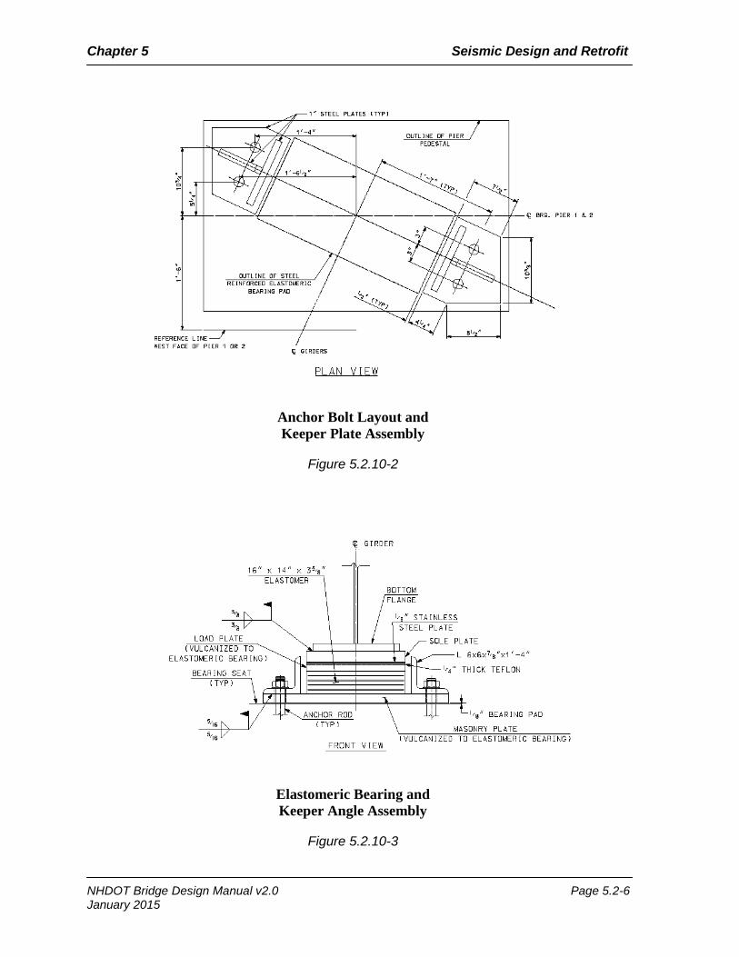
4) Pier Bearing Detail
All pier expansion bearing assemblies shall be detailed with keeper restraints (e.g., keeper plates or keeper blocks) for seismic movement in the transverse direction. The designer shall determine if keeper restraints will be located at each bearing or at the center and/or ends of the pier. See Figures 5.2.10-1, 2 and 3 for examples.
B. Seismic Zone 2
All connections and load path elements shall be designed for seismic forces by analysis in accordance AASHTO 3.10 and AASHTO Guide Specifications for LRFD Seismic Bridge Design.
Elastomeric Bearing and Keeper Plate Assembly
Figure 5.2.10-1
NHDOT Bridge Design Manual v2.0 Page 5.2-5 January 2015
Chapter 5 Seismic Design and Retrofit
Anchor Bolt Layout and Keeper Plate Assembly
Figure 5.2.10-2
Elastomeric Bearing and Keeper Angle Assembly
Figure 5.2.10-3
NHDOT Bridge Design Manual v2.0 Page 5.2-6 January 2015
Chapter 5 Seismic Design and Retrofit
5.3 Rehabilitation of Existing Bridges
5.3.1 General
In general, retrofit work on piers and abutments will not be required. Most retrofit work shall consist of providing lateral restraint at bridge bearings and providing adequate seat width. The Department may require more extensive analysis and retrofit for major bridges, or if a unique situation exists. The decision to include seismic retrofit of piers and abutments will be made on a case-by-case basis by the Department. The level of seismic retrofitting that would be required for a particular rehabilitation or reconstruction project will be dependent on several factors such as ADT, importance of the bridge, age of the bridge, economic considerations, whether the bridge is on the Interstate, State, or Local System, etc.
When options for the designer are limited, providing adequate seat widths for an existing superstructure is a high priority over other potential retrofit measures; it is a key component of the Department’s objective to prevent span loss. If attainment of adequate seat widths is not a practical option, using such measures as isolation bearings should be explored. To prevent significant transverse movement of the superstructure, concrete keeper blocks or steel keeper angles may be rigidly attached to the pier or abutment caps between the beams. When evaluating seismic retrofit options, all reasonable measures should be explored for possible implementation.
The following two FHWA reports should be used as guides for seismic retrofit of bridges: • Report No. FHWA-IP-87-6, “Seismic Design and Retrofit Manual for Highway Bridges” • Report No. FHWA-RD-94-052, “Seismic Retrofitting Manual for Highway Bridges”
NHDOT Bridge Design Manual v2.0 Page 5.3-1 January 2015

Chapter 5 Seismic Design and Retrofit
Page intentionally left blank.
NHDOT Bridge Design Manual v2.0 Page 5.3-2 January 2015
Chapter 5 Seismic Design and Retrofit
5.4 Seismic Isolation Bearings
5.4.1 General
Seismic design incorporating seismic isolation devices may be considered for bridges classified as critical, provided that the following requirements are satisfied:
• The design of the seismic isolation devices is in accordance with AASHTO Guide Specifications for Seismic Isolation Design, as modified in this Manual. The response modification factor for all elements shall be taken as 1.0.
• It can be demonstrated that the performance characteristics of the bearings will provide a necessary benefit for the design of the bridge substructures.
• The specific isolation systems and manufacturers being considered shall meet the approval of the Design Chief.
• At the preliminary and final design stages, the design of the isolators must be closely coordinated with all isolation device manufacturers approved by the Design Chief.
• Non-seismic loads and movements are determined and adequately accounted for in the design of the isolation systems(s).
• The larger displacement resulting from an increase in the period of vibration due to increased flexibility is adequately accommodated and detailed (such as providing adequate roadway joint movement capability or designing and detailing a portion of the backwall to break away upon superstructure impact).
• Design and cost information shall be obtained for a cost evaluation of the various seismic design alternatives.
• Life-cycle cost of additional and specialized bearing inspections shall be calculated. • Issues related to long-term performance and maintenance shall be identified.
NHDOT Bridge Design Manual v2.0 Page 5.4-1 January 2015

Chapter 5 Seismic Design and Retrofit
Page intentionally left blank.
NHDOT Bridge Design Manual v2.0 Page 5.4-2 January 2015
Chapter 5 Seismic Design and Retrofit
5.5 Seismic Design Requirements for Retaining Walls
5.5.1 General
The seismic design for retaining walls shall be determined in accordance with the AASHTO 11.5.4.2 and 11.6.5 as noted below:
• If the wall is located in Seismic Performance Zones 1-3 and meets the criteria as noted in AASHTO 11.5.4.2, a no-seismic analysis option can be taken for the internal and external seismic stability design of the wall.
• Seismic analysis shall be considered for walls greater than 30-ft. (9.1-m) and located in Seismic Zones 2 or higher as described in AASHTO C11.5.4.2.
NHDOT Bridge Design Manual v2.0 Page 5.5-1 January 2015

Chapter 5 Seismic Design and Retrofit
Page intentionally left blank.
NHDOT Bridge Design Manual v2.0 Page 5.5-2 January 2015
Chapter 5 Seismic Design and Retrofit
References
1. American Association of State Highway and Transportation Officials (AASHTO), AASHTO LRFD Bridge Design Specifications, 7th Ed., 2014, Washington, D.C.
2. American Association of State Highway and Transportation Officials (AASHTO), AASHTO Guide Specification for LRFD Seismic Bridge Design, 2nd Ed., 2011, Washington, D.C.
3. American Association of State Highway and Transportation Officials (AASHTO), Standard Specifications for Highway Bridges, 17th Ed., 2002, Washington, D.C.
4. American Association of State Highway and Transportation Officials (AASHTO), Guide Specifications for Seismic Isolation Design, 3rd Ed., 2010, Washington, D.C.
5. Connecticut Department of Transportation, Bridge Design Manual, 2003 Ed. Retrieved from http://www.ct.gov/dot/cwp/view.asp?a=2303&q=300834
6. Federal Highway Administration (FHWA), Seismic Retrofitting Manual for Highway Structures: Part 1 - Bridges, Publication No. FHWA-HRT-06-032, January 2006. Retrieved from www.fhwa.dot.gov/publications/research/infrastructure/bridge/06032/06032.pdf
7. Federal Highway Administration (FHWA), Seismic Design and Retrofit Manual for Highway Bridges, Publication No. FHWA-IP-87-6, 1987. Retrieved from http://trid.trb.org/view.aspx?id=280995
8. Federal Highway Administration (FHWA), Seismic Retrofitting Guidelines for Highway Bridges, Publication No. FHWA-RD-83-007, 1983. Retrieved from http://trid.trb.org/view.aspx?id=199229
9. New Hampshire Department of Transportation Bureau of Bridge Design, Bridge Design Manual, October 1, 2000, Concord, NH
10. Rhode Island Department of Transportation, LRFD Bridge Design Manual. Retrieved from http://www.tmc.dot.ri.gov/business/contractorsandconsultants.php
11. Washington State Department of Transportation, Bridge Design Manual (BDM) M 23-50. Retrieved from http://www.wsdot.wa.gov/Publications/Manuals/M23-50.htm
NHDOT Bridge Design Manual v2.0 Page 5.R-1 January 2015

Chapter 5 Seismic Design and Retrofit
Page intentionally left blank.
NHDOT Bridge Design Manual v2.0 Page 5.R-2 January 2015
January 2015 – v 2.0
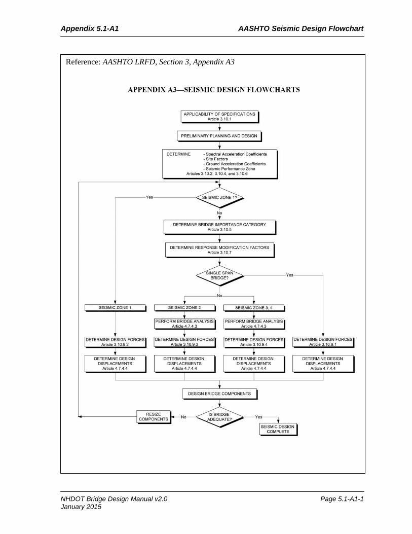
Appendix 5.1-A1 AASHTO Seismic Design Flowchart
Reference: AASHTO LRFD, Section 3, Appendix A3
NHDOT Bridge Design Manual v2.0 Page 5.1-A1-1 January 2015

Appendix 5.1-A1 AASHTO Seismic Design Flowchart
Page intentionally left blank.
NHDOT Bridge Design Manual v2.0 Page 5.1-A1-2 January 2015