Seismic damage and retrofit studies of the Mori-Sada building.
89
Lehigh University Lehigh Preserve eses and Dissertations 1-1-1983 Seismic damage and retrofit studies of the Mori- Sada building. Shiunn-Jang Wang Follow this and additional works at: hp://preserve.lehigh.edu/etd Part of the Civil Engineering Commons is esis is brought to you for free and open access by Lehigh Preserve. It has been accepted for inclusion in eses and Dissertations by an authorized administrator of Lehigh Preserve. For more information, please contact [email protected]. Recommended Citation Wang, Shiunn-Jang, "Seismic damage and retrofit studies of the Mori-Sada building." (1983). eses and Dissertations. Paper 2367. brought to you by CORE View metadata, citation and similar papers at core.ac.uk provided by Lehigh University: Lehigh Preserve
Transcript of Seismic damage and retrofit studies of the Mori-Sada building.
Lehigh UniversityLehigh Preserve
Theses and Dissertations
1-1-1983
Seismic damage and retrofit studies of the Mori-Sada building.Shiunn-Jang Wang
Follow this and additional works at: http://preserve.lehigh.edu/etd
Part of the Civil Engineering Commons
This Thesis is brought to you for free and open access by Lehigh Preserve. It has been accepted for inclusion in Theses and Dissertations by anauthorized administrator of Lehigh Preserve. For more information, please contact [email protected].
Recommended CitationWang, Shiunn-Jang, "Seismic damage and retrofit studies of the Mori-Sada building." (1983). Theses and Dissertations. Paper 2367.
brought to you by COREView metadata, citation and similar papers at core.ac.uk
provided by Lehigh University: Lehigh Preserve

SEISMIC DAMAGE AND RETROFIT STUDIES
OF THE MORI-SADA BUILDING
by
Shiunn-Jang Wang
A Thesis
Presented to the Graduate Committee
of Lehigh University
in Candidacy for the Degree of
Master of Science
in
Civil Engineering
Lehigh University
May 1983

ProQuest Number: EP76643
All rights reserved
INFORMATION TO ALL USERS The quality of this reproduction is dependent upon the quality of the copy submitted.
In the unlikely event that the author did not send a complete manuscript and there are missing pages, these will be noted. Also, if material had to be removed,
a note will indicate the deletion.
uest
ProQuest EP76643
Published by ProQuest LLC (2015). Copyright of the Dissertation is held by the Author.
All rights reserved. This work is protected against unauthorized copying under Title 17, United States Code
Microform Edition © ProQuest LLC.
ProQuest LLC. 789 East Eisenhower Parkway
P.O. Box 1346 Ann Arbor, Ml 48106-1346

CERTIFICATE OF APPROVAL
This thesis is accepted and approved in partial
fulfillment of the requirements for the degree of Master
of Science.
'^j /3. Of* Da te)
Professor in Charge
hairman of Department
XI
CERTIFICATE OF APPROVAL
This thesis is accepted and approved in partial
fulfillment of the requirements for the degree of Master
of Science.
XDa te)
Professor in Charge
hairman of Department
XX

ACKNOWLEDGEMENT
It is a pleasure for the author to record his
gratitude to Dr. Le-Wu Lu for his valuable guidance and
encouragement during this study. The author also wishes
to express his deep appreciation to Mr. Ching-Hwei Chue
and Professor Matsui of Kyushu University for their help
in translating the Japanese reports.
Special thanks are also due to Miss Christian C. Su
for her help in drawing the figures. Sincere appreciation
is also extended to Dr. Shosuke Morino in Kyushu
University for providing much valuable information.
The research assistantship supported by the Fritz
Engineering Laboratory of Lehigh University is sincerely
appreciated.
xxx

Table of Contents
ABSTRACT 1 1. INTRODUCTION 3 1.1 Background 3 1.2 Objactives 5 1.3 Outline of Report 6 2. SEISMIC DAMAGE ANALYSIS OF THE MORI-SADA BUILDING 7 2.1 Description of the Building 7 2.2 Observed Damage 7 2.3 Previous Studies 8 2.4 Elastic Analysis 9
2.4.1 Modelling 9 2.4.2 Result and Discussion 11
2.5 Inelastic Analysis 12 2.5.1 DRAIN-2D Program 13 2.5.2 Modelling 14 2.5.3 Selection of Comparison Parameters 16 2.5.4 Result and Discussion 16
2.6 Summary 18 3. SEISMIC ANALYSIS OP THE MORI-SADA BUILDING 20
RETROFITTED WITH CONCENTRIC AND ECCENTRIC BRACING SYSTEMS
3.1 General 20 3.2 Structure Selection 20 3.3 Design of Bracing Member 21 3.4 Models for Bracing Members 24 3.5 Modelling of Braced Frames 25 3.6 Lateral Stiffness per Unit Volume 26 3.7 Results and Discussion in Phase 1 Study 27 3.3 Results and Observations of Phase 2 Study 28 4. EFFECT OF ECCENTRICITY RATIO AND CONNECTION TYPE 30
OF BRACING MEMBERS ON THE DYNAMIC RESPONSE OF THE RETROFITTED BUILDING
4.1 Introduction 30 4.2 System Selection 31 4.3 Modelling 32 4.4 Results and Observations 32 4.5 Discussion 34 4.6 The Effect of Eccentricity on Lateral Stiffness 36 4.7 Summary 37
5. CONCLUSIONS 39 TABLES 41 FIGURES 46
xv

REFERENCES 63
VITA ,. 66
V '

ABSTRACT
A 4-story steel frame building, which is located in
the downtown of Sendai, Japan and houses the Mori-Sada
company, experienced a major earthquake in 1978 and
suffered severe structural damage. In this report,
elastic and inelastic analyses have been performed to
investigate the causes of the damage. The calculated
damage to structural members correlates well with the
observed damage of the building. It is found that the
major cause of the damage is the lack of lateral
stiffness of the moment-resistant frame. The sudden
change of column stiffness and the soft soil condition
are also believed to be the contributing factors.
Different braced systems are introduced into the
structure as a means of retrofitting the building. It is
found that a vertical uninterrupted bracing system can
make this building safer during futher earthquakes.
Also, a trend is observed that, in terms of increase in
elastic stiffness per unit volume of bracing material,
concentrical K-bracing is more efficient than
eccentrically K-bracing and concentrical X-bracing
systems, and pin-ended bracing is better than rigid-ended
bracing.

A study of the effect of bracing eccentricity on the
dynamic behavior of the retroffited building with
eccentrical K braces is made. The results show lateral
stiffness of the frame drops rapidly when bracing
eccentricity increases. Hence, for the purpose of
increasing lateral stiffness, the bracing eccentricity
ratio should be kept as small as possible. Also, it is
found that in terms of lateral stiffness rigid-ended
bracing is more efficient than pin-ended bracing for
bracing eccentricity ratios between 0.1 to 0.3.
1. INTRODUCTION
1.1 Background
On June 12, 1978, the Miyagi-Oki earthquake took
place near the city of Sendai, Japan. It caused
siginificant damage to the Mori-Sada building, whose
structural system consists mainly of moment-resistant
frames. The major damage was the plastic distortion in
the columns of the third story of the building. Until
now, no report has provided any clear explanation for the
damages. The primary objective of this study are to
investigate the reasons of the observed damages and to
study the means of retrofitting the building.
By performing elastic and inelastic analyses of the
Mori-Sada building, it is found out that the major cause
of the damage is the lack of lateral stiffness
characteristic of the moment-resistant frame. It is
proposed to install some bracing members into the moment
frame as the means of retrofitting the building. Three
bracing systems, concentrical K-bracing, eccentrical K-
bracing and concentrical X-bracing systems, are adopted
in the study.
The analyses of the retrofitted building with
different bracing systems show that concentrical bracing
can easily provide the needed lateral stiffness and it is
more efficient than tne eccentrical bracing system so far
as elastic behavior is concerned. However, the cyclic
inelastic behavior of the concentrically braced frame is
questionable. Many studies confirm that the cyclic
inelastic behavior of concentrically braced frames is
strongly influenced by the cyclic post-buckling behavior
of the individual braces and its hysteresis loops is
pinched and deteriorating [11, 14]. Previous research
has shown that eccentrically braced frame is more
reliable than concentrically braced frame in the
inelastic range [15, 16]. For this reason, a detail
study of the use of eccentrical K-bracing system as a
means of retrofitting the building is carried out.
Instead of studying the design of the eccentrical bracing
member, the study emphasizes the effects of varying the
amount of eccentricity and the connection types (pin
connection vs rigid connection) on the dynamic response
of the retrofitted building.

1.2 Objectives
The main objectives of this research are:
1. To study the elastic and inelastic dynamic
response of the Mori-Sada building.
2. To provide a qualitative explanation of the
observed column failure.
3. To study the dynamic response of the building
with different bracing system; and to compare
the performance of the retrofitted structure
with that of the original structure. The
bracing systems to be examined are
a. concentrical X-bracing.
b. concentrical K-bracing.
c. eccentrical K-bracing.
4. To study the effect of varying the amount of
eccentricity on the dynamic response of the
retrofitted building with eccentrical K-
bracing members..
5. To study the effect of the different
connection types of the bracing members on the
dynamic response of the retrofitted building.

1.3 Outline of Report
Following Chapter 1, which gives an introduction to
the study, this report presents the results of three
seperate, by coordinated, studies. In Chapter 2, elastic
analysis and inelastic analysis of the original building
are performed by using computer programs SAPIV and
DRAIN-2D and explanations of the observed damage are
provided. By installing different bracing systems into
the original building, several retrofitted structures
have been developed and analyzed. The results are
presented in Chapter 3.
A series of inelastic dynamic analyses of the
building retrofitted with eccentrical K bracing are
carried out in Chapter 4. The principal variables are the
bracing eccentricity and the bracing connection. The
bracing eccentricity varies form zero(concentrical
bracing) to 0.9 times the length of the girder of the
braced bay. Two connection types, pin and rigid, are
chosen. The results are given in Chapter 4. General
conclusions of the study are presented in Chapter 5.

2. SEISMIC DAMAGE ANALYSIS OF THE MORI-SADA BUILDING
2.1 Description of the Building
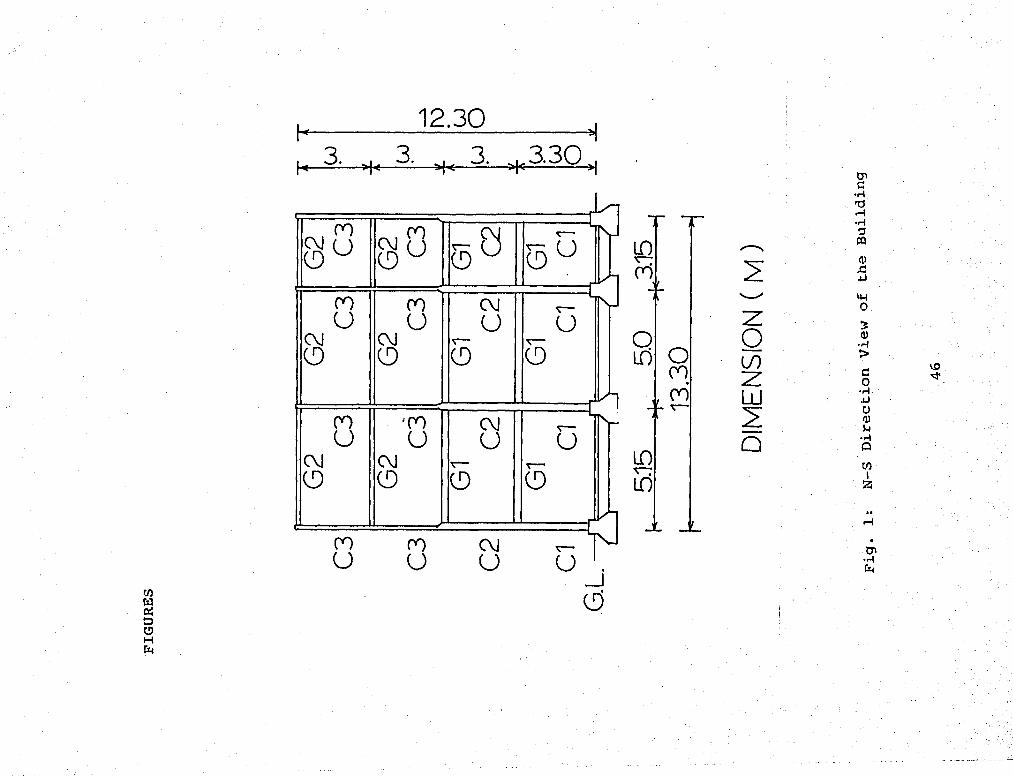
The Mori-Sada building, which is located in Sendai,
Japan, was completed in 1971. The building, shown in
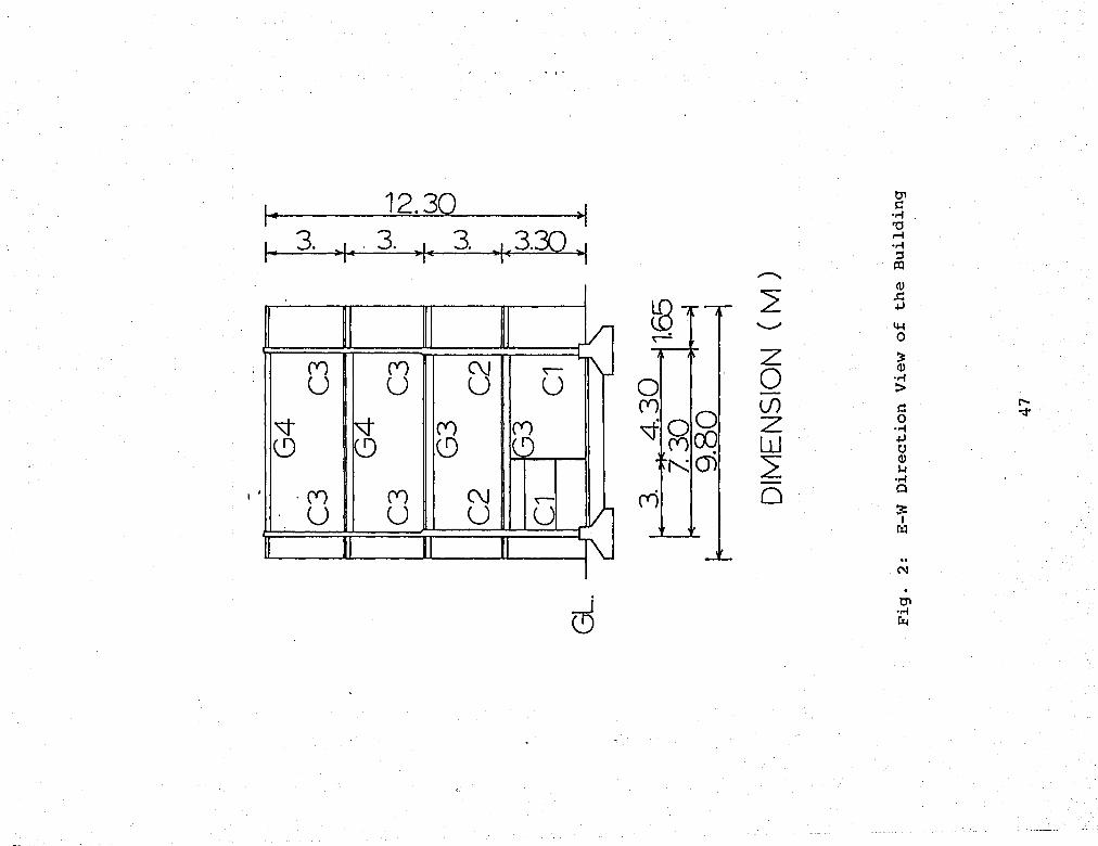
Fig.l, 2, and 3, is a 4-story office building, 7.3m x
13.3m in plan and 12.39m high, oriented with its
longitudinal dimension in the N-S direction. It has
three bays in the N-S direction and one bay in the E-W
direction. The building has two full moment-resisting
steel frames in the longitudinal direction, which is the
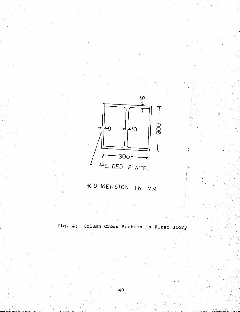
weak direction of the columns. In order to increase the
stiffness about the weak axis, two 9mm thick plates were
welded to the wide flange columns in the first story
(Fig. 4). All the other columns and girders are standard
Japanese wide flange shapes. The member sizes of this
structure are shown in Table 1.
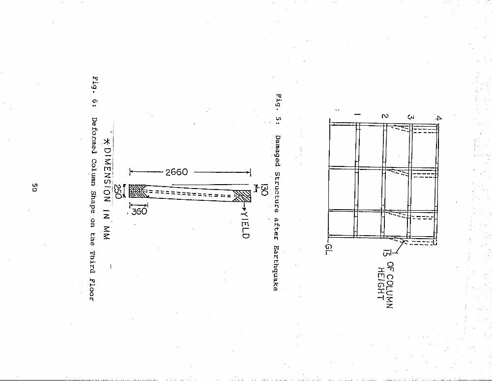
2.2 Observed Damage
Because the earthquake ground motions are stronger
in the N-S direction, the principal damages are found in
the longitudinal moment-resistant frames. As shown in
Fig. 5, there was a 1/15 permanent deflection in the
third floor after the earthquake. The deformed shape of
the columns in the third story is shown in Fig. 6. The

plastic deformation at the top and the bottom of the
column is almost the same. Some cracks were found around
the footings. Furthermore, the exterior wall on the
third floor failed in shear and all the windows on the
third floor were broken.
2.3 Previous Studies
There are several reports in Japanese containing
information about this building. A check of design
adequacy of this building has been carried out in Ref.
[10]. The results show that the design of this building
satisfied all the requirements of the applicable Japanese
code. Also, the quality of construction of this building
has been investigated and found to be very
satisfactory [3]. Furthermore, dynamic analyses with
elastic material properties, shear building and lumped
mass assumptions have been performed [1, 3, 10]. The
energy method developed by Ben Kato [13] has been used in
accessing the safety of the structure. In this method,
the safety of a structure is evaluted by comparing
structure's energy dissipating capacity with earthquake
input energy. The results show that the energy
concentration ratio is the highest between the second and
third floor levels. The reports, therefore, conclude that
the observed damage in the columns was due to the high
8

energy dissipation. However, no report offers any
clearly explanation why the energy was so highly
concentrated between these floors. Another suggestion is
that it is the sudden change of the column stiffnesses at
the second floor level that caused the problem [18].
But, no analytical study has been carried out to support
this suggestion.
2.4 Elastic Analysis
There are two purposes of performing the elastic
analysis in this study:
1. As a check for the correctness of the
theoretical model by comparing the results
obtained with the results presented in the
Japanese reports.
2. As a check for the inelastic analysis results.
2.4.1 Modelling
SAPIV program [5] is used to perform the elastic
analysis. Because the results of this analysis are used
to be compared with the results of the previous studies,
in which two dimensional planar frame models were used,
the building is treated as two parallelal planar
structures. The assumptions of the model used in this
analysis are:

1. The foundation is infinitely rigid.
2. The structure is symmetrical in plan; hence,
torsional deformation is neglected.
3. The girders provide all the flexural
stiffnesses and any additional stiffness due
to the floor slabs is ignored.
4. The structures are of the moment-resisting
type and resist deformations only by the
moments developed at the ends of the girders
and columns.
5. Shear deformation in the girders and columns
is neglected.
6. There is no extension (or contraction) between
floors, since it is assumed that the
structures are infinitely rigid in the
vertical direction.
7. All masses are concentrated at the floor
levels.
8. The mass of each floor moves horizontally.
Vertical motion is not considered because of
assumption 5. The rotational inertia
associated with each joint is considered.
The node and element numbering adopted in the analysis is
shown in Pig. 7. The three-dimensional beam elements are
10

used for the beams and columns. The mode superposition
method is used in the time-history analysis. The £-W
direction, 25 seconds earthquake record obtained from the
strong motion instruments installed in the Architectural
and Civil Engineering building of the Tohoku University
in Sendai is used as the base excitation [19].
2.4.2 Result and Discussion
The natural period of the building computed by SAPIV
was 1.05 second which is very close to the natural period
1.12 second given in Ref. [1]. This comparison provides
some confidences in the results of this analysis.
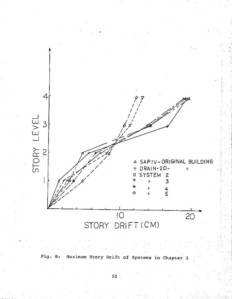
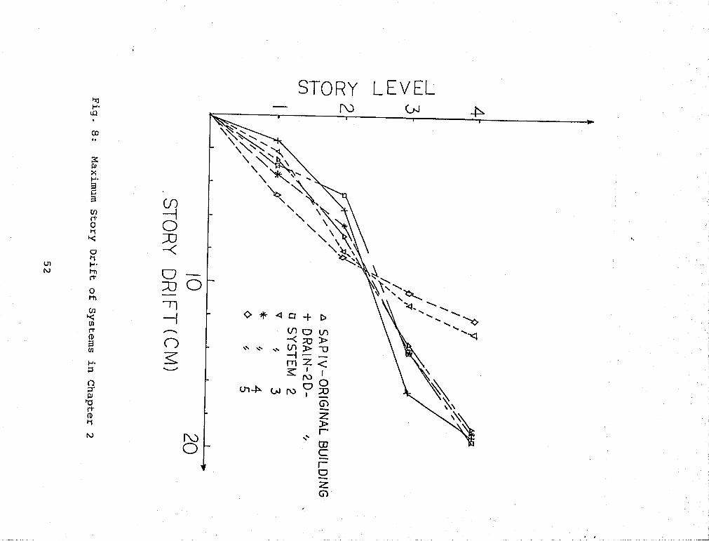
A plot of the maximum story drift of each floor is
shown in Fig. 8 and the maximum bending moment in the
columns are listed in Table 2. It is shown that the
moments in some columns exceeded the plastic moments very
early during the earthquake. Inelastic behavior
therefore occurred in the structure soon after the
earthquake had begun. The results of the elastic
analysis of course are no longer valid after initial
yielding.
11

2.5 Inelastic Analysis
The results of the elastic analysis clearly
indicated that the behavior of the building during the
earthquake is far from being elastic. The purpose of
performing the inelastic analysis in this study is to
understand the true behavior of the building during the
earthquake in order to find out the reason for the
observed damages.
There are three different sizes of columns in this
building and they are designated as Section 1 for the
columns of the first story, Section 2 for the second
story, and Section 3 for the third and fourth stories.
As mentioned in the previous section, it has been
suggested that the change of the column stiffness at the
second floor level may have caused the energy
concentration. To verify this, four structures with
varying column sizes have been developed and analyzed by
the DRAIN-2D program. The descriptions of these four
structures and the reason to develop them are stated as
follows:
1. System 1 — The original Mori-Sada building.
2. System 2 — Changing the size of columns in the
second story from Section 2 to Section 1.
12

The motive is to increase the stiffness
change at the floor level 2, which may
cause an increase in the energy
concentration.
3. System 3 — Changing the size of the columns on the
third story from Section 3 to Section 2.
The idea is to eliminate the stiffness
change at the second floor level.
4. System 4 — Including changes in both System 2 and
System 3.
5. System 5 — Using Section 1, the strongest section,
for all the columns to eliminate the
column stiffness change. The purpose of
this system is to investigate the ability
of the moment frame to resist lateral
load.
2.5.1 DRAIN-2D Program
DRAIN-2D is a general purpose computer program for
the inelastic response of planar structures subjected to
earthquake ground motions. The program concepts and
features are described in Ref. [12]. The structure is
idealized as a planar assemblage of discrete elements.
Analysis is done by the Direct Stiffness Method, with the
nodal displacements as the unknowns. Each node possessed
13

up to three displacement degrees of freedom, as in a
typical plane frame analysis. The analysis uses a step-
by-step procedure with the yield state of each element
checked at the end of each time step. The tangent
stiffness modifications and the equilibrium corrections
for any imbalance due to changes in state are applied at
the end of each time step. The time step is held
constant, and no iteration is used.
2.5.2 Modelling
The node and element numbering adopted in this
analysis is the same as that in the elastic analysis (
Fig. 7). The following points may be noted:
1. Masses are associated only with the horizontal
and rotational displacement at the floor
levels.
2. Beam-column elements are used throughout for
every member.
3. Each girder is represented by a single element
so that plastic hinges may form at the girder
ends only.
4. Element lengths from center to center of
joints have been assumed throughout.
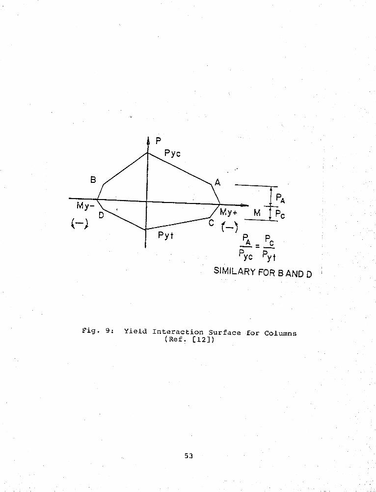
5. P-M interaction is taken into account for the
14
columns, assuming interaction surfaces as for
steel I-sections (Fig. 9).
6. A strain hardening ratio of 5% is assumed for
all element.
7. The P-A effect is taken into account by
adding geometric stiffness to the column
stiffness.
3. All the structures are analyzed with the
original stiffness-proportional damping, which
is assumed to be equal to 5% of the critical
damping for the first mode. The original
sstiffness-proportional damping is chosen
because it is felt to be more indicative of
the true conditions [15]. Also, it
distributes the damping effect throughout the
structure and not just at the mass points.
9. All the analyses are performed with a 0.01
second time step, which has been chosen after
several trial runs. Considerable inelastic
activity occures during this time span, and
the results with this time step are
sufficiently similar to the results with a
smaller (0.005 seconds) time step.
10. A yield stress of 2500 kg/cm2 is assumed
15

throughout the study.
2.5.3 Selection of Comparison Parameters
Instead of using ductility ratio to express the
ductility demands on the structural members, the DRAIN-2D
program prpvides values of the total plastic
deformations, which are believed to be more meaningful
physically than those rather artifical ratio [12]. Those
total deformations' are computed as indicated in Fig. 10,
by accumulating the plastic rotation during all positive
and negative plastic excursions. In this study, the
maximum story drift and maximum total plastic hinge
rotation of columns on each floor are chosen to be the
parameters for comparison.
2.5.4 Result and Discussion
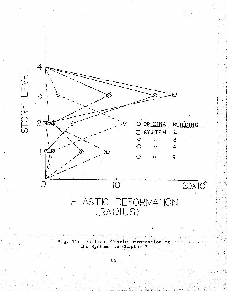
The maximum total plastic hinge rotations of the
stories are shown in Fig. 11 and maximum story drifts are
shown in Fig. 8. The plastic deformations concentrate at
the columns of the third story where severe column damage
occurred. The calculated damage to the structural members
seem to correlated well the actual damage of the
building. However, the permanent deflection of the third
floor level computed by DRAIN-2D after 25 second
earthquake excitation is 10cm which is smaller than the
16

observed damage, 13cm. It has been reported in Ref. [10]
that the building rests on a soft soil, which was
previously a rice field. Ref. [17] reports that the deep
layers of the relatively soft soil are particularly
dangerous for the building because of their acceleration
amplification characteristics. Hence, it is believed
that the infinitely rigid foundation assumption may be
the reason for the difference between predicted result
and observed damage. Another factor is that the ground
motion record used in the analysis is not obtained from
the same building.
The results for System 2 indicate that the increase
of the column size of the second story tends to increase
the damage in the third story. Furthermore, the damage
mechanism is changed in System 3, in which the major
damage occurs at the columns on the second story instead
of the third story. In this system, the column stiffness
changes at the first floor level. From these two
observations, a trend that the energy dissipation tends
to concentrate on the floor where the column stiffness
changes may be established.
The most interesting finding is in the response of
System 5. This system is supposed to be a very safe
17
structure because every column in this system has double,
even triple, flexural stiffness than the corresponding
column in the original structure. However the analysis
results show that the story drift control of this system
is not improved very much. Moreover, the plastic hinges
are found at the first floor. It indicates that neither
the increase of column flexural stiffness nor avoiding
the column stiffness change can improve this building.
Hence, the energy concentration are not the major reasons
for the damage. The real problem is that the lateral
stiffness of the moment frame is too low. The excessive
deflection developed during the earthquake because of the
low lateral stiffness and the resulting increase in the
P-A effect caused high stresses and plastic deformation
in the columns.
2.6 Summary
By performing elastic dynamic analysis on the moment
frame of the original building and inelastic dynamic
analyses on the building and its four modifications, the
reasons for the damages can be noted as follows:
1. The moment-resisting frame produced excessive
deflections due to the lack of lateral
stiffness. This excessive deformation
18
increases the P-A effect, which in turn
increases the stresses in members and causes
the plastic deformations.
2. The sudden change of column stiffness at the
second floor level causes the damages to be
concentrated in the third story.
3. The soft soil under the building possibily
amplified the input acceleration and increased
the damage.
4. The building was designed by the weak column
- strong beam design concept. That is the
reason why the plastic hinges formed only in
the columns.
19
3. SEISMIC ANALYSIS OF THE MORI-SADA BUILDING RETROFITTED
WITH CONCENTRIC AND ECCENTRIC BRACING SYSTEMS
3.1 General
Since the main problem of the Mori-Sada building is
the weak drift control characteristic of the moment-
resistant frame, it is proposed to investigate how the
performance of the building can be improved by installing
an internal bracing system.
This study consists of two phases. The first phase
is to investigate the behavior of the bracing systems
with different arrangements of bracing members in a
concentrical X-bracing system. The second phase is to
study the behavior of the structures with different
bracing systems. The bracing systems included are the
concentrical X-bracing, concentrical K-bracing and
eccentrical K-bracing systems.
3.2 Structure Selection
In the first phase, in which the behavior of the
structures with different arrangements of bracing members
are investigated, only concentrical X-braced frames are
studied. Five systems have been chosen and are shown in
Fig. 12. In the second phase, two different sizes and
20
two different connection types of the braces are
considered. The structures used in this phase of study
are shown in Fig. 13, Fig. 14, and Table 3.
3.3 Design of Bracing Member
The seismic lateral design forces are taken as
specified by the Uniform Building Code [20]. According to
this code the design base shear is
V = ZIKCSW (3.1)
where W is the total dead load and applicable portions of
other load, which has been taken to be full live load in
this study. The numerical coefficient C is determined
from G = 1/15T, where T = the fundamental elastic period
of the structure and suggested by the code as T = 0.05
H/D. (H/D is the height-to-width ratio of building) The
site resonance factor 3 depends on the ratio of building
period T to characteristic site period Ts. In this
study, S is taken as 1.5. The code also specifies that
the product CS need not exceed 0.14 and therefore is
taken to be 0.14. The coefficients Z, I and K are taken
as 1. As required by the code, all bracing members in the
braced frame are designed for 1.25 times the force
determined from Equation 3.1.
21

The following formulas presented in Ref. [4] for
designing diagonal tension bracing members are used.
Design Condition 1: lateral Stiffness Under Working
loads.
Ab= ~o (3-2) EL&-<r.L2-Ee h
y »-
in which
E = modulus of elasticity;
F = \ tension force in bracing member due to lateral
loads plus P-A shear;
a = sum of elongation of columns due to lateral
loads plus P-A shear;
C = axial compressive stress in beam due to lateral
loads plus P-A shear;and
A = 0.002h
L = length of bracing member;
L - length of braced bay
h = height of the braced bay.
22

Design Condition 2: Strength and Stability Under
Design Ultimate Loads.
Strength Requirement:
Lb ~ Lb Lbffg Lbec - , N Ab = EH + —- + -— + EPX (3.3) 0.85<TyL EhL
2 0.850TyEh 0.85<TyL2
in which
EH = story shear due to the applied lateral
loads(L.F. =1.30);
EP-J^ = total applied gravity load above the story
which contributes to the P shear in the story
(L.F. = 1.30).
<T = yield stress level of the diagonal brace. All
other terms have been defined previously.
Stablity Requirement:
Lb Lb°g Lbec « ,, ^ Ab = —; + — + \ Ep2 (3-4)
EhL^ 0.85<F Eh 0.85<F L*
in which Ep2 = total gravity load above the story which
contributes to the shear in the story (L.F. = 1.70). All
other terms have been defined previously.
Design Condition 3: Brace Slenderness Requirement.
rbi Le/300 (3.5)
in which r^is the radius of gyration of the bracing
23

member and Le is the effective length of the diagonal
brace between points of support, as defined in the AISC
Specification [2]. The above formula provide the minimum
area for the bracing member. Although these procedures
are recommended only for concentrical X-braced frames, in
order to compare the performace of different bracing
systems, the same bracing member are used for other
bracing systems. After performing the calculations
metionsed above, the equal leg single angle section
75x75x9 (Japanese shape) and the double angle section
3x3x3/8 (US shape) are chosen. The latter has almost
twice the stiffness of the first one. The reason for
choosing two different sections is to investigate the
effect of bracing member size on the behavior of the
structure.
3.4 Models for Bracing Members
In the past studies of braced frames, the hysteresis
behavior of primarily axially loaded bracing members has
been modeled in one of the several ways, such as:
elastic in tension and compression, tension-only elastic
model, tension-yield and compression-yield, or tension-
yield and compression-buckling. These models neglected
the energy dissipation characteristics of bracing members
in the post-buckling range. In Ref. [8], Jain presented
24

a hysteresis model which accounts for the energy
dissipation characteristics of bracing members. This
model has been incorporated with the DRAIN-2D program as
Buckling Element EL9 [9]. This element type is used as
the model of pin-ended bracing member. Another model, End
Moment-Buckling Element (EL10), which is a combination of
buckling element (EL9) and beam-column element (EL2) is
used as the model of rigid-connected bracing member.
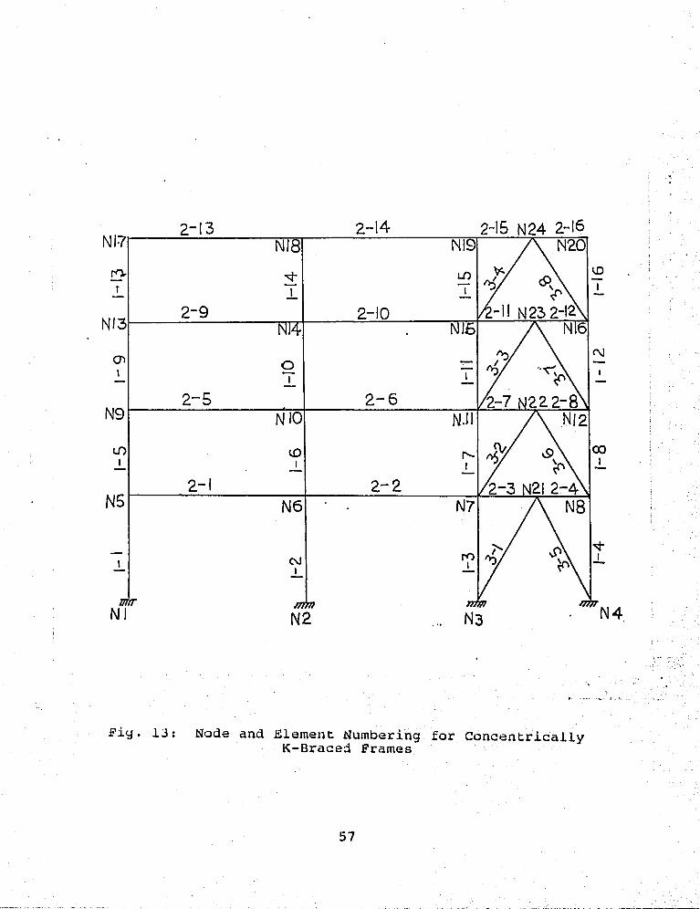
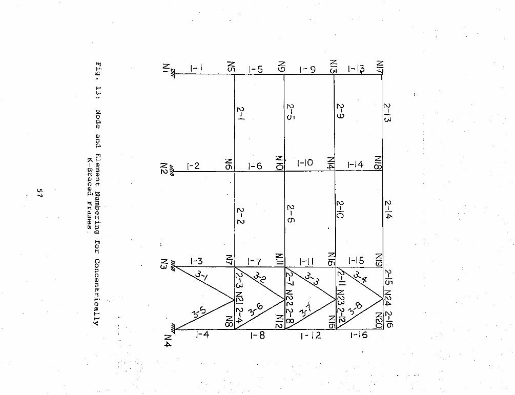
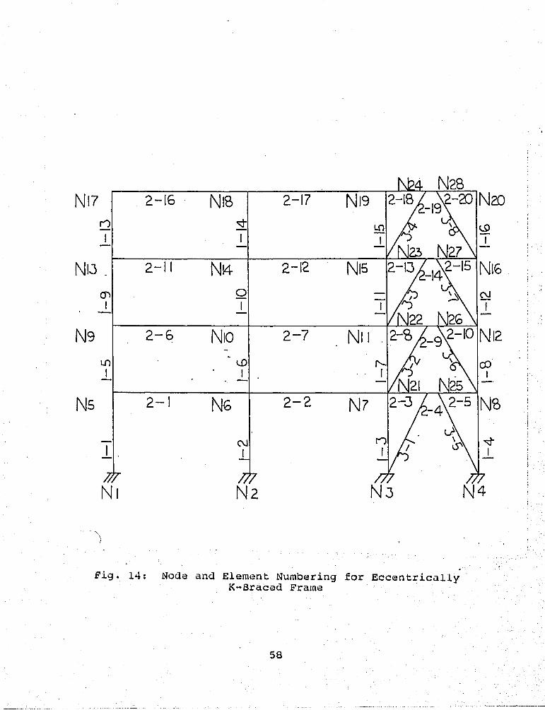
3.5 Modelling of Braced Frames
The node and element numbering for the braced
systems used in this study is shown in Fig. 13 and Fig
14. The following points may be noted with regard to
modelling:
1. All the modelling for the moment frame remain
the same as described in Chapter 2.
2. Buckling element (EL9) is used for pin-ended
bracing member. End moment-buckling element
(EL10) is used for rigid-connceted bracing
member.
3. The maximum compressive load was assumed to be
the Euler's buckling load.
4. The cycling load (PyncK equal to 25/(L/r)
times the yield load.
25

5. Time step 0.01 is used.
6. The first 5 seconds of the Miyagi-Oki
earthquake record are used in order to reduce
coraputer time.
7. Because the shear force in the link of an
eccentrical bracing system is very large,
there is a great possibility that the link may
fail in shear. In order to consider this mode
of failure, the plastic moment Mp of the link
is taken as the smaller value of the normal
plastic moment of the link and the end moment
when the link fails in shear. The latter is
computed as the yield force times the length.
8. The eccentricity ratio (e/L) is 0.1 for the
eccentrical K-bracing system.
3.6 Lateral Stiffness per Unit Volume
In order to compare the performance of different
bracing systems, the lateral stiffness per unit volume,
which is the total lateral stiffness divided by the
volume of the member, is introduced. The lateral
stiffness is defined as the total base shear divided by
the maximum lateral deflection at the top of the
structure. The lateral stiffness per unit volume of a
braced structure is used to show the effeciency of using
26
various bracing systems.
3.7 Results and Discussion in Phase 1 Study
The responses of the structures in phase 1 are given
in Table 4. First of all, the damages in System 4 and 5
are found in the columns in the second floor and are
worse than the observed and evaluated damages of the
original structure. This indicates that installing
bracing members in the third story or in the third and
fouth story would only strengthen the floors being braced
and would cause damages to occur in the unbraced floors.
This observation is very similar to what was found in
Chapter 2.
The results also show that there are no plastic
hinges in the first three systems whcih have
uninterrupted vertical bracing systems. Furthermore, the
bending moments in the columns in the third story of
these systems are only half of those in the original
structure and the maximum stroy drifts are only one fifth
of those in the original structure. These observations
show that the performance of the building can be
significantly improved by installing a continous bracing
system.
27

Comparing the story drifts and bending moments in
the columns of these systems, it is found that the
bracing in the larger bay offers more story drift
control, yet does not increase the maximum moment in
columns. Another way of comparing bracing performance is
to examine the lateral stiffnesses per unit volume
provided by the bracing systems. They are given in Table
5. It may be seen that System 3 has the highest
stiffness per unit volume and is the most efficient
system.
3.8 Results and Observations of Phase 2 Study
Nine systems (Table 3) have been analyzed in this
phase of study. Their responses are shown in Table 6. The
lateral stiffness per unit volume for each system is
computed and listed in Table 6. The observations that
may be made from this phase of study are as follows:
1. The behavior of all the bracing systems are
within elastic range. No plastic hinge is
found in any system. This shows that a
vertical uninterrupted bracing system can make
this building safer for similar earthquake.
2. When only the elastic behavior is considered,
concentrical K-bracing system is more
28

efficient than concentrical X-bracing and
eccentrical K-bracing systems.
3. When using the same brace size, concentrical
X-bracing system provides more story drift
control than other bracing systems. On the
other hand, pin-ended bracing provides less
story control than rigid-ended bracing.
4. Increasing the bracing size seems can increase
the lateral stiffness per unit volume and more
story drift control can be gained.
29

4. EPPECT OP ECCENTRICITY RATIO AND CONNECTION TYPE OP
BRACING MEMBERS ON THE DYNAMIC RESPONSE OP THE
RETROFITTED BUILDING
4.1 Introduction
It is shown in Chapter 3 that the concentrical
bracing member is more effecient than eccentrical bracing
member in the elastic range. However, many studies have
shown that the eccentrical bracing member is more
reliable in inelastic behavior than the concentrical
bracing member [15, 11]. Hence, a study on the
eccentrical bracing system is carried out in this
Chapter.
The basic characteristics of an eccentrically
braced frame may be noted by examining the elastic as
well as plastic behavior of a simple diagonally braced
frame [6] , such as shown in Pig. 15. The dependence of
the elastic frame stiffness on the paramethers e/L is
illustrated in Pig. 15. By varying the ratio e/L from 0
to 1, the frame changes in character from a
concentrically braced frame to a conventional moment-
resisting frame. Por all intermediate values of e/L, the
frame becomes eccentrically braced. The curve clearly
show the advantages of bracing the frame to gain lateral
30
stiffness in the system.
It has bean noted by Hjelmstad that the results
shown are only for a one-story frames and that the member
boundary conditions in one-story frames are different
from those found in multistory frames [6]. As an
extension of the Hjelmstad's study, the effect of the
eccentricity ratio and connection type on the dynamic
response of multisonry frame are investigated, using the
Mori-Sada building as the skeleton structure.
4.2 System Selection
Theoretically speaking, eccentrically braced frames
is designed by the plastic methods, where the force
distribution is determined by a lower bound moment
balancing technique [7], with the lateral loads
determined by an applicable building code. Since in this
study only the effects of changing eccentricity ratio and
connection type are examized, it is appropriate and
convience to use the girders and columns of the original
building and one of the bracing sizes adopted in Chapter
3, the double angle 3x3x3/8. By varying the eccentricity
ratio from 0 to 0.9, 20 structures with the same member
sizes are analyzed by the DRAIN-2D program.
31

4.3 Modelling
All the input parameters are the same as those used
in chapter 3. In order to study the inelastic behavior
of the retrofitted buildings, 1.5 times the Miyagi-Oki
earthquake record is used as the base excitation.
4.4 Results and Observations
The 20 structures analyzed are divided into two
groups. Group 1 contains 10 systems with pin-ended
bracing member and group 2 contains 10 systems with
rigid-ended bracing member. The results of analyses are
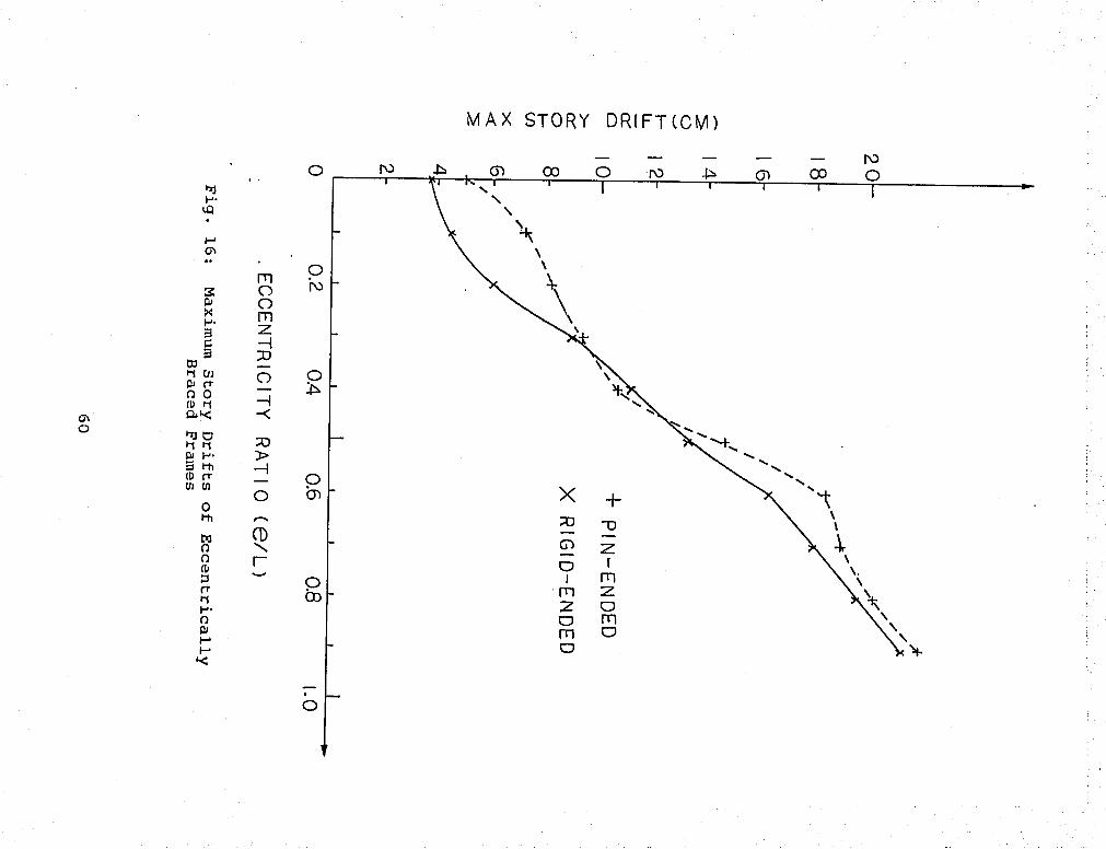
present in Fig. 16, 17, 18 and Table 7. The following
observations have been made during the course of the
investigation and from the computer results.
1.. As shown in Pig. 16, the maximum horizontal
story drift of the frame increases as the
bracing eccentricity increases. This means
that an increase in the eccentricity tends to
reduce the stiffness of the structures. This
will be discussed in more detail later.
2. All the bracing element in the group 1
structures did not fail in tension. However,
3 structures in group 2 did have bracing
failure. The results also show that higher
32

axial forces would toe presented in regid-ended
bracing members than in pin-ended bracing
members.
3. Shear link failure are found in group 2. Nine
links fail in the structure with e/L=0.6, two
with e/L=0.7 and three with e/L=0.8. These
three structures happen to have bracing
failure also. It was first believed that the
link failure may be related to the failure of
the bracing members. But, it was later found
that the stress imbalances at the eccentric
nodes and the vertical displacements at these
nodes were unreasonable. This problem will be
investigated and discussed in detail in a
later section.
4. As shown in Table 7, the maximum accumulated
plastic hinge rotations of both beams and
columns increase with increasing eccentricity.
This is another indication that increase in
bracing eccentricity tends to decrease the
stiffness of the structure. However, it is
observed that all the maximum plastic hinge
rotations occur on the columns of the third
floor. So, the damage mechanism of the
33

retrofitted frame with various bracing
eccentricies would be the same as in the
original moment-resisting frame.
4.5 Discussion
As metioned in Section 4.4, the member forces and
the vertical displacements of the failed link appear to
be unreasonable. The member forces do not satisfy
equilibrium at the eccentric nodes and the vertical
displacements are too large. It is felt that a detailed
study is necessary to provide an explanation for the
problem.
The same subject has been investigated by Roeder and
Popov [15]. Their suggestion is that it is due to the use
of original stiffness-proportional damping. This damping
property is also used in this study because it predictes
a more realistic distribution of the damping effects and
does not lead to a decrease in damping after membber
yielding. It also offers more computational stability in
the analysis.
The DRAIN-2D computer program handles this type of
damping by augmenting the structural stiffness at the
start of the analysis and adding a load term at the end
34

of each time step throughout the analysis [12]. The load
term is added to the unbalanced load vector, which
includes unbalanced loads due to change of yield state,
as the corrections for the nonlinearities of the system.
The unbalanced load vector is then added to the next time
step, because no iteration is performed within the time
step. By carefully examining the results, the imbalance
and large vertical displacement did not start until the
eccentric element started to exhibit large amounts of
yielding. Before the eccentric member yields, the
vertical velocities of the eccentric nodes are zero.
However, after a bracing yields, the vertical velocity of
the eccentric node becomes very large. These large
vertical velocities produce large damping loads to be
added to the bracing nodes after each time step.
Eventually, it is these large vertical damping loads that
lead to extra stresses in the link and cause it to fail.
It is thus confirmed that the imbalance in member forces
is caused by the application of a load through the
unbalanced load vector used in the computer program.
It is therefore apparent that the predicted link
failure may not be realistic and the results should not
be included in the comparison study. However, the story
drift and the base shear of the entire structure have not
35

been affected very much by the local link failure and it
is felt that they can be used as a rough indication of
the stiffness of the structure in the study.
4.6 The Effect of Eccentricity on Lateral Stiffness
In this section, the variation of lateral stiffness
of the retrofitted frame with eccentric K bracing frame
is discussed. As defined in Chapter 3, the lateral
stiffness of the braced frame can be computed as the
total base shear divided by the lateral deflection at the
top of the structure. The total base shear can be
computed by summing up the maximum shear forces in the
columns on the first floor. The base shears of the
systems in this study have been computed and are shown in
Pig. 17. The base shear is maximum when e/L=0.6 for the
case of pin-ended bracing and when e/L=0.7 for rigid-
ended bracing.
The stiffness terms are normalized dividing the
calculated stiffness by the stiffness of the original
frame retrofitted with concentrical bracing, (i.e.
eccentricity equals zero). The results are shown in Pig.
13. Once again, it may be observed that the stiffness
decreases as the eccentricity increases. For
eccentricity ratios greater than about 0.5, the lateral
36

stiffness for both pin-ended and rigid-ended bracing
systems decreases rather slowly. This means that for
large bracing eccentricities, the type of connection has
only a small effect on the lateral stiffness. On the
other hand, when the eccentricity is small (e/L < 0.2),
the rigid-ended bracing systems have 40% more lateral
stiffness than the pin-ended bracing systems.
For rigid-ended bracing system, stiffness drops
considerably when e/L is greater than 0.2. For pin-ended
bracing system, stiffness drops rather rapidly between
e/L=0.1 and e/L=0.3. This shows that in eccentrically
braced frames rigid-ended bracing system would be more
efficient than pin-ended bracing system in improving
lateral stiffness in e/L ratio smaller than about 0.3.
4.7 Summary
The results of this study may be summarized as
follows:
1. The maximum story drifts and the maximum
accumulated plastic hing rotations of the
retrofitted structures would increase as the
bracing eccentricity increases. On the other
hand, the lateral stiffness of the retrofitted
37

structure would decrease as the bracing
eccentricity increases. Hence, for the
purpose of increasing lateral stiffness, the
ratio e/L should be kept as small as possible.
2. Base shear is maximum when e/L=0.6 for the
case of pin-ended bracing and when e/L=0.7 for
rigid-ended bracing cases.
3. Lateral stiffness is not sensative to bracing
eccentricity when e/L>0.5.
4. Pin-ended bracing systems lose more stiffness
than rigid-ended systems for e/L ratio between
0.1 and 0.3. Also within this range of e/L
ratio, rigid-ended bracing system is more
efficient in improving lateral stiffness than
pin-ened bracing system.
5. By using original stiffness-proportional
damping property, the DRAIN-2D program would
provide unrealistic link failure when a
bracing member yields. This is caused by the
application of load through the unbalanced
vector used in the computer program.
38

5. CONCLUSIONS
The major conclusions of this study are:
1. The principal cause for the damage of the
Mori-Sada buidling is the lack of lateral
stiffness of the moment frame in the
longitudinal direction. The sudden change of
column stiffness and the soft soil condition
probably also contributed to the damage.
2. A trend that the energy dissipation tends to
concentrate on the floor where the column
stiffness changes is observed.
3. By introducing a vertical uninterrupted
bracing system, the building could
considerably perform better in futher
earthquakes.
4. If concentrical X-bracing system is used to
retrofit the building, a vertical
uninterrupted bracing in the longest bay is
more efficient than other arrangements.
5. When only the elastic behavior is considered,
concentrical K-bracing system is more
efficient than concentrical X-bracing and
eccentrical K-bracing systems.
5. When using the same brace size, concentrical
39
X-bracing system provides more story drift
control than other bracing systems. On the
other hand, pin-ended bracing provides less
story control than rigid-ended bracing.
7. If eccentric K-bracing system is used, the
maximum story drifts and the maximum
accumulated plastic hinge rotations of the
retrofitted structures would increase as the
bracing eccentricity increases. Also, the
lateral stiffness of the retrofitted structure
would decrease as the bracing eccentricity
increases. Hence, for the purpose of
increasing lateral stiffness, the ratio e/L
should be kept as small as possible. On the
other hand, pin-ended bracing systems lose
more stiffness than rigid-ended systems for
e/L ratio between 0.1 and 0.3. Also within
this range of e/L ratio, rigid-ended bracing
system is more efficient in improving lateral
stiffness than pin-ened bracing system.
40

TABLES
Table 1 Member Sizes of the Building
Size
H-300x300xlOxl5 (2 9mm plates welded)
H-300x300xlOxl5
H-250x250x9xl4
H-294x200x8xl2
h-244xl75x7xll
H-336x249x8xl2
H-294x200x8xl2
Type Designation
Column Cl
Column C2
Column C3
Girder Gl
Girder G2
Girder G3
Girder G4
41

Table 2 Maximum Bending Moment in Columns Computed by SAPIV
to Reach Plastic Moment
3.15sec
3.15 sec
3.15 sec
3.15 sec
3.7 sec
3.1 sec
3.1 sec
3.1 sec
3.1 sec
3.1 sec
3.1 sec
3.1 sec
11.3 sec
3.25 sec
3.15 sec
10.85 sec
Column No. Max Moment (kg-cm)
Plastic M< (kg-cm)
1 3.132X10⁶ 2.168xlOS
2 3.372X10⁶ H
3 3.54 xlO6 ii
4 3.122xl06 H
5 1.527xl06 1.125x10s
6 2.252X10⁶ II
7 2.474xlOS H
8 1.84 xlO6 n
9 1.359xl06 7. 3xl05
10 1.977xl0S H
11 2.15 xlO6 n
12 1.634xl06 H
13 8.07 xlO5 n
14 1.286xlOS II
15 1.406xlOS II
16 1.011x10s n
42
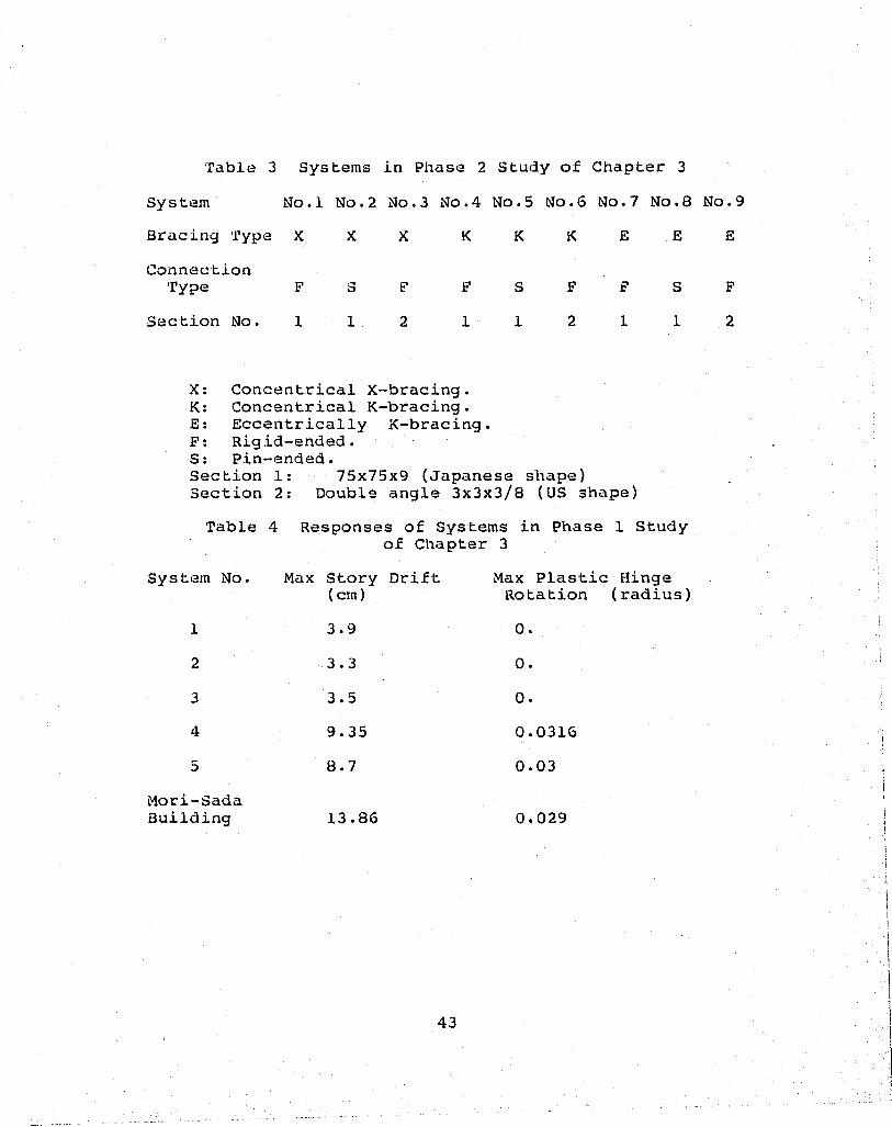
Table 3 Systems in Phase 2 Study of Chapter 3
System No.l No.2 No.3 No.4 No.5 No.6 No.7 No.8 No.9
Bracing Type XXX KKKEEE
Connection Type PSF FSFFSF
Section No.11 2 11 2 1 1 2
X: Concentrical X-bracing. K: Concentrical K-bracing. E: Eccentrically K-bracing. F: Rigid-ended. S: Pin-ended. Section 1: 75x75x9 (Japanese shape) Section 2: Double angle 3x3x3/8 (US shape)
Table 4 Responses of Systems in Phase 1 Study of Chapter 3
Max Plastic Hinge Rotation (radius)
0.
0.
0.
0.0316
0.03
0.029
System No. Max Story Drift (cm)
1 3.9
2 3.3
3 3.5
4 9.35
5 8.7
Mori-Sada Building 13.86
43

Table 5 Comparison among Three Arrangements of Bracing Systems
System 1 Sys tem 2 System 3
Base Shear (kg) 24993 23828 23899
Max Story Drift (cm) 3.9 3.5 3.3
Lateral Stiffness 6410 (kg/cm)
6308 7242
Lateral Stiffness per Unit Volume
(kg/cm4) 6.536x10 -3 7.23x10 -3 7.69x10 -3
Table 6 Reponse of Systems in Phase 2 of Chapter 3
stem No.
Max Moment in Column (kg-cm)
Max Moment in Beams (kg-cm)
Base Shear (kg)
Max Story Drift (cm)
Lateral Stiffness per Unit Volume (kg/cm. •)
1 1309350 921983 23075 3.5 0.00672
2 1417204 991893 24272 3.57 0.00693
3 1563593 941428 23353 2.7 0.00732
4 1687915 1305945 29331 4.0 0.00712
5 1701547 1555320 29331 4.1 0.00736
6 1817830 1637250 28390 3.4 0.00826
7 2073915 1856746 36869 6.73 0.0056
8 2003112 1763541 36892 6.69 0.0056
9 1185054 1177899 22114 3.7 0.0058
44
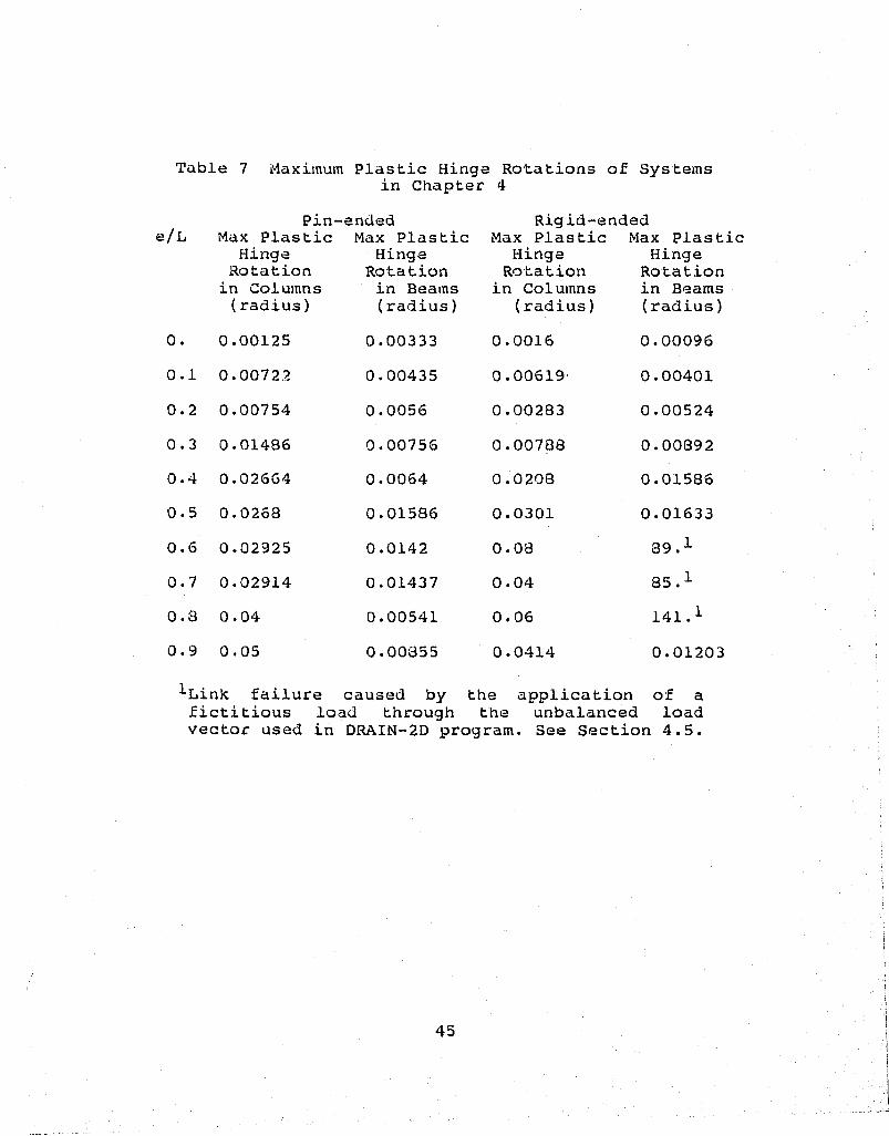
Table 7 Maximum Plastic Hinge Rotations of Systems in Chapter 4
Pin-ended Rigid-ended e/L Max Plastic Max Plastic Max Plastic Max Plastic
Hinge Rotation
in Columns (radius)
0. 0.00125
0.1 0.00722
0.2 0.00754
0.3 0.01486
0.4 0.026G4
0.5 0.0263
0.6 0.02925
0.7 0.02914
0.3 0.04
0.9 0.05
Hinge Rotation in Beams (radius)
0.00333
0.00435
0.0056
0.00756
0.0064
0.01586
0.0142
0.01437
0.00541
0.00355
Hinge Rotation
in Columns (radius)
0.0016
0.00619
0.00283
0.00708
0.0203
0.0301
0.03
0.04
0.06
0.0414
Hinge Rotation in Beams (radius)
0.00096
0.00401
0.00524
0.00892
0.01586
0.01633
39.1
85.1
141.1
0.01203
-'•Link failure caused by the application of a fictitious load through the unbalanced load vector used in DRAIN-2D program. See Section 4.5.
45

FIGURES
G2 C3
C3
C2
a GL-£s
C3
G2
G1
G1
C3
C2
a
G2 C3
G2 C3
G1 C2
G1 C1
a
G2 C3
C3 :GT=
C2
G1 a
GO
GO
JL
u ho GJ O
GO 00 o
I, 5.15 ,„ 5.0 .,3.15 -*-K-
h 13.30 H H
DIMENSION ( M)
Fig. 1: N-S Direction View of the Building
46
w w D
H
12.30
3. ... 3. 3. ^3.30 -I
->H- ->K-
00
CD^
CM CD
00
oo U
CM CD
oo U
oo CM M CDU O a
CM CD
00 U
CM
CD
00 U
CM CD
CM u CD
00 U
CM u
CD U
U O
CD
CD
U
LQ ol
O LO
LO v-r LO
O 00 00
o
UJ I
en c
•H
H •H D CQ
<l> A
0
> C 0
•H xJ U 0) u
•H P W
I 53
Cn •H
vo

GL.
•■ . G4 C3 C3
G4 C3 C3
G3 C2 C2
a G3
Z5 C1
Z5 ->H- 4.30 7 30 9.80
1.65
A
.,
_L
CO
GO
B
D
DIMENSION (M)
Fig. 2: E-W Direction View of the Building
47
12.30 * 3. >. 3. . 3. ,.,3.30 „
oo
CD
oo U
00 (J
CD
00 U
CM U
00 CD
CM (J
U 00 a.
(J I I
CD
IB i:
< %—;r
o oo
00
o 00
~T"
O 00
en c
•-H
iH •H 3 « 0) JS +J
o
o > uo c: z 0
UJ 4J u
2 Q a
S W
• ■
• cn

3.85 , 3.45
k 3.00 , 4.30 ^
h 7-^Q H
DIMENSION (M )
Fig. 3: Floor Plan of the Building
48

00
*1
U>
*1 H 0 O
13 H P» 3
O Hi
(T D" 0)
CD c H &
ifl
D
m Z (/} o
N
o
JL _JL
K 515 ->K- 5.QQ H+ 3-15 >|
GO
bo en
GO
Ik en
300-
WELDED PLATE
-^-DIMENSION IN MM
Fig. 4: Column Cross Section in First Story
49

^
n o
3 a o o w en
to
o n- 0
H- D
"3 H-
w
to rt 0
m :z CO

4
3
2
J i
11
i1
// / K
' ^5 OF COLUMN HEIGHT
■GL
Fig Damaged Structure after Earthquake
O ID
-YIELD
Fig. 6:
250 1 X DIMENSION IN MM
Deformed Column Shape on the Third Floor
50
*1 I—
en
o
o re 1 i-ti I 0
§ :^i rt> i UJ CJj
o 0 m c Z! 3 3 !2!M
i!8 •3 (Ii — .
2 0 3 2 (T s: rD
H3 CT H- l-i i & *! H 0 0 h
Ul
w
(T
C

NI7I
I
NI3
2HQ
2-7
N18
1" i
N 1-4-1
2-1
2-8
NI9
i
NI5
2-12 N20
i
2-9 NI6
i
N9 2-4
21
"Nlol 2-5
N 2-6
CO
i
N5
ID I
N6 2-2
i
N7 2-3
oo i
H8
CM I I I
Nl N2 N3 N4
Fig. 7: Node and Element Numbering for SAPIV
51

Ul
o (U
DJ
Cb
(C 3 fD
n-
c 3 o' ro
Mi o
w na H <
Z» ^ 1-5 ID 1-9
(V
z: 1-13 q
I 4*
N>i 1-2 CD
2.
1-6 5
i to
I—10 2.
ro
o
1-14 00
OJ 1-3 1-7 =
i IOJ
z: 4> 1-4 oo 1-8
ro i
HI en
ro i
CD
ro 1-12 o>
ro oo
i
-15 U3
ro i
ID
16 I
ro
A SAPIV-ORIGINAL BUILDING + DRAIN-2D- D SYSTEM 2 * * 3 *
<> 4 5
10 STORY DRIFT (CM)
20
Pig. 8: Maximum Story Drift of Systems in Chapter 2
52
CO
s X H- 3 C 3 w
STORY LEVEL
3
O 3' U) *0 ft CD
to
CO 1 •
0 t-t o ' 1
XI o -< h H- Hi ° ^ 0 ZO o Hi
1
CO ~n H
IT ,—> CD 3 en o
no O
I
-< ^D > NV s- sv (/I > TJ
m z <
<■*-£> OJ rv> *p 5
> I—
DD C r* o
en
_j
SIMILARYFORBANDD
Fig. 9: Yield Interaction Surface for Columns (Ref. [12])
53

FORCE OR i MOMENT ' A
ACCUMULATED POSITIVE DEFORMATION • = SUM OF POSITIVE YIELD EXCURSIONS
MAXIMUM POSITIVE DEFORMATION
»».
EXTENSION OR ROTATION
-ACCUMULATED NEGATIVE DEFORMATION = SUM OF NEGATIVE YIELD EXCURSIONS
NOTE THAT MAXIMUM NEGATIVE DEFORMATION IS ZERO, ALTHOUGH ACCUMULATED NEGATIVE DEFORMATION IS NOT ZERO
Fig. 10: Procedure for Computation of Accumulated Plastic Deformation (Ref. [12])
54
LJJ > LJJ
>-
O 00
20X10
PLASTIC DEFORMATION (.RADIUS)
Fig. 11: Maximum Plastic Deformation of the Systems in Chapter 2
55

STORY LEVEL
un
l- ID
n (D
Oi
0) rr re
0) nj i-1
5 0) |T
O H- 3 n
T5 o n re re Hi •1 0
t-i
P» IT H- O D
O Hi
GO
"D
3D >
> GO H O
O m o
5 o

SYSTEM SYSTEM 2
SYSTEM 3
X X X /
..
SYSTEM 4 SYSTEM 5
Fig. 12: Different Bracing Arrangement in X-bracing System
56
NI7"
ra r
NI3-
Ch t
N9
i
N5
vnr N;
2-13
2-9
2-5
2-1
NI8
i
o i
NIO
ID l
N6
i
2-14
2-10
2-6
mm N2
2-2
2-15 N24 2-16
Fig. 13: Node and Element Numbering for Concentrically K-Braced Frames
57
O & (U
0» 3 & IB
I
o Pi <z
c
0) fi>
3 0) 13
H- D
ua
tti o
n o n
n-
o pj
NI7 n
No CT>
N9
un
N5
2-16 NI8
Ni
N* o
I
2-6 NlO
KS)
N6
2-17 Nl9 2-18 / A2-23 rvd
m
2-12 N|5
2-7 Nl I
r--
N24 N28
N25 N27 2-13/^2-15
'N22 N26 2-6 X_9\2-I0
N2I N25 2-2
N20
(£ j_
Nl6
J_
NI2
CO
CM I
777 N2
Pig. 14: Node and Element Numbering for Eccentrically K-Braced Frame
58

U1 CD
*1
M *■
0 & (I)
&> 3 &
_ & I (D
CD 3 (D 3 (T
PJ o (U
c
PJ 01 3 h (t> p-
3 IQ
Hi O h
W o n (D 3 (T h I— o p»
01 ^ C3 ^ Z^ J-l 1-5 1-9 ■ 1-13
r\j ^ 1-2
rv>
en
t\3 I
ro
ro I
ro
I —10
ro
no
J4.
ro
en
CP
ro

CO CO UJ z Li. U_
co UJ
< cr
UJ >
UJ cr
Fig. 15: Variation of Frame Stiffness for Different Eccentricity Ratio (Ref. [63)
59

fil o o CD 3 (T H H- O H-
rt H- 0
CD Hi
cn
Ul
< h
rr H- O 3
0 Ml
h ui 3 fO
w rf H- Hi Hi 3 fD CO (/)
_H,
•1
O H- Hi Hi (D H (B 3 (T
O O
RELATIVE FRAME STIFFNESS
ro ^ ai CD

o H LL.
Q
>-
o I- co X <
+ PIN-ENDED
X RIGID-ENDED
1.0
. ECCENTRICITY RATIO (e/L)
Fig. 16: Maximum Story Drifts of Eccentrically Braced Frames
60
MAX STORY DRtFT(CM)
o
G\
p m s o ro p o
3 m
c H 3
CD 3D
n o (D i-l
o o
CLk< -< *1 D H M 33 » H- > 3 Hi —| <1> ft co en O
o fr 0 Hi l~>
n CD o \ o r~ (T •1
O bo
n
3D "D
(?> z O i
1 m m z 2 o O m m o o

3. XIO
0 O.I 0.2 0.3 0.4 0.5 0.6 0.7 OS 0.9
ECCENTRICITY RATIO O/U
.0
Fig. 17: Base Shear For Eccentrically Braced Frame s
61

BASE SHEAR (Kg)
o\
CO pj
en
ID OJ h
*1 o »-i
W o o oi
P"
H- O PJ
w
o (U
3 en
n O O m
o
p
o ro
o CM
o
H 9 .
X) o > C7>
O o ,—, ^1 (D \ o r CP
o CD

A PIN-ENDED
O RIGID-ENDED
0 0.1 0.2 0.3 0.4 0.5 0.6 07 0.8 0.9 1.0
ECCENTRICITY RATIO (e/L)
Pig. 18: Variation of Lateral Stiffness for Eccentrically Braced Frames
62

to
»*3
w ° <: (5 P»
Mi
00 P
o
en
Mi M> S3 rt> 0) (fl
o ro
m o o o m .OJ 7 —i o 33 * O H o -< en
53 o > CD
O o
CD -N)
\ o r 00
o (£>
o
RELATIVE FRAME STIFFNESS p p p p o o o p — to 'oi '.£» tn en *-^j 'co
o 'CD
REFERENCES
[1] Architectural Institute of Japan. Damage Investigation Report on Miyagi Earthquake, in Japanese.
[2] AISC. Steel Construction 8th ed edition, American Institute of Steel
Construction, New York, 1931.
[3] Architectural Research Institute in Japan Construction Department. Damage Report of the Miyagi Earthquake. Monthly Publication, No.71..
[4] ASCE. Plastic Design in Steel — A Guide and Commentary 2nd edition, ASCE, 1971.
[5] Bathe, K.J., Wilson, L.E. and Peterson, F.E. SAP IV — A Structural Analysis Program for Static
and Dynamic Reponse of Linaear System University of California, Berkeley, California,
1974.
[5] Hjelmstad, K.D., and Popov, E.P. Cyclic Behavior and Design of Link Beams. Reprint SC-7, ASCE Structuree Congress, New Orleans
Oct. 1932.
[7] Home, M.R. A Moment Distribution Method for the Analysis and
Design of Structures by the Plastic Theory. Proceedings of Institute of Civil Engineers Vol
3(No.1), April, 1954.
[3] Jain, A. K. Hysteresis Behavior of Bracing Members and Seismic
Response of Braced Frames with Different Proportions.
PhD thesis, University of Michigan, July, 1978.
63
[9] Jain A.K. and Goal, S.C. Hysteresis Models for Steel Members Subjected to
Cyclic "Buckling of Cyclic End Moments and Buckling (User's GuTde fo'r DRAIN-2D: EL9 and EL10).
Technical Report No. UMEE73R6 , University of Michigan, December, 1978.
[10] JS3C Inquiry Commission of Earthquake Damage on Steel Structures. Reports on the Steel Structure Damage in Miyagi
Earthquake. JS3C, Japan Steel Structure Construction Vol 14(No.
153) , September, 1978. in Japanese.
[11] Kahn, L.F.' and Hanson, R.D. Inelastic Cycles of Axially Loaded Steel Members. ASCE Jounral of the Structural Division Vol 102,
May, 1976.
[12] Kanaan, A.E. and Powell, G.H. DRAIN-2D - A General Purpose Computer Program for
the Dynamic Analysis of Inelastic Plane Structures.
Technical Report EERC Report 73-6, University of California, Berkeley, April, 1973.
[13] Kato, Ben and Akiyama, Hiroshi. Seismic Design of Steel Buildings. ASCE J. of Structural Div. (ST8):pl709-1720,
August, 1932.
[14] Popov, E.P. and Black, R.G. Steel Structs Under Severe Cyclic Loadings. ASCE J. Structural Division Vol 107(ST9),
September, 1931.
[15] Roeder, C. W. and Popov, E.P. Inelastic Behavior of Eccentrically Braced Steel
Frames Under CycTTc Loadings. Technical Report, University of California,
Berkeley, August, 1977.
[16] Roeder, C. W. and Popov, E.P. Eccentrically Braced Steel Frames for Earthquakes. ASCE Journal of the Structural Division Vol
104(ST3) :P391-413, March, IdlT.
64

[17] Seed, H.B. and Idriss, I.M. Influence of Local Soil Conditions on Building
Damage Potential During Earthquakes. Technical Report EERC 69-15, University of
California, Berkeley, December, 1969.
[18] Steel Material Club. Damages of the Steel Structures by Earthquake, Wind
and Snow, in Japanese.
[19] Toshio Shiga, Akenori Shibata, Junichi Shibuya and Junichi Jakahashi. Observations of Strong Earthquake Motions and
Nonlinear Response Analyses of the Building of Architectural and Civil Engineering Department, Tohoku University.
Technical Report Paper No. 301, AIJ, March, 1980. in Japanese.
[20] Uniform Building Code International Conference of Building Officials,
Whittier, CA, 1976.
65
VITA
Shiunn-Jang Wang, born August 5, 1957 in Taipei,
Taiwan, R.O.C, is the son of San-Ching Wang and Yen-Yin
Ding.
After graduating from National Taiwan University,
where he got his B.S. degree in civil engineering, he
served two years in Chinese Marine Corps as an logistic
officer.
Mr. Wang came to Lehigh University on August 1931
for his M.S. degree. He has been emplyed as a research
assistant in the Fritz Engineering Laboratory, where he
has been associated with the project "Earthquake
Resistance of High-Rise Buildings Systems". He has also
bean involved with the work of the Council on
TallBuildings and Urban Habitat, which is headquatered at
Lehigh.
66