Seismic Assessment and Strengthening of the … 2017 Seismic Assessment and...Seismic Assessment and...
10
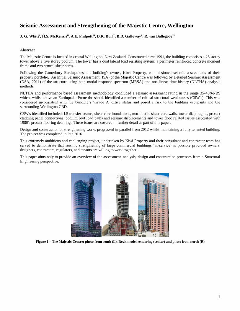
1 Seismic Assessment and Strengthening of the Majestic Centre, Wellington J. G. White i , H.S. McKenzie ii , A.E. Philpott iii , D.K. Bull iv , B.D. Galloway v , R. van Ballegooy vi Abstract The Majestic Centre is located in central Wellington, New Zealand. Constructed circa 1991, the building comprises a 25 storey tower above a five storey podium. The tower has a dual lateral load resisting system; a perimeter reinforced concrete moment frame and two central shear cores. Following the Canterbury Earthquakes, the building's owner, Kiwi Property, commissioned seismic assessments of their property portfolio. An Initial Seismic Assessment (ISA) of the Majestic Centre was followed by Detailed Seismic Assessment (DSA, 2011) of the structure using both modal response spectrum (MRSA) and non-linear time-history (NLTHA) analysis methods. NLTHA and performance based assessment methodology concluded a seismic assessment rating in the range 35-45%NBS which, whilst above an Earthquake Prone threshold, identified a number of critical structural weaknesses (CSW's). This was considered inconsistent with the building’s ‘Grade A' office status and posed a risk to the building occupants and the surrounding Wellington CBD. CSW's identified included; L5 transfer beams, shear core foundations, non-ductile shear core walls, tower diaphragms, precast cladding panel connections, podium roof load paths and seismic displacements and tower floor related issues associated with 1980's precast flooring detailing. These issues are covered in further detail as part of this paper. Design and construction of strengthening works progressed in parallel from 2012 whilst maintaining a fully tenanted building. The project was completed in late 2016. This extremely ambitious and challenging project, undertaken by Kiwi Property and their consultant and contractor team has served to demonstrate that seismic strengthening of large commercial buildings ‘in -service’ is possible provided owners, designers, contractors, regulators, and tenants are willing to work together. This paper aims only to provide an overview of the assessment, analysis, design and construction processes from a Structural Engineering perspective. Figure 1 – The Majestic Centre; photo from south (L), Revit model rendering (center) and photo from north (R)
Transcript of Seismic Assessment and Strengthening of the … 2017 Seismic Assessment and...Seismic Assessment and...
1
Seismic Assessment and Strengthening of the Majestic Centre, Wellington J. G. White
i, H.S. McKenzie
ii, A.E. Philpott
iii, D.K. Bull
iv, B.D. Galloway
v, R. van Ballegooy
vi
Abstract
The Majestic Centre is located in central Wellington, New Zealand. Constructed circa 1991, the building comprises a 25 storey tower above a five storey podium. The tower has a dual lateral load resisting system; a perimeter reinforced concrete moment
frame and two central shear cores.
Following the Canterbury Earthquakes, the building's owner, Kiwi Property, commissioned seismic assessments of their
property portfolio. An Initial Seismic Assessment (ISA) of the Majestic Centre was followed by Detailed Seismic Assessment
(DSA, 2011) of the structure using both modal response spectrum (MRSA) and non-linear time-history (NLTHA) analysis
methods.
NLTHA and performance based assessment methodology concluded a seismic assessment rating in the range 35-45%NBS
which, whilst above an Earthquake Prone threshold, identified a number of critical structural weaknesses (CSW's). This was
considered inconsistent with the building’s ‘Grade A' office status and posed a risk to the building occupants and the
surrounding Wellington CBD.
CSW's identified included; L5 transfer beams, shear core foundations, non-ductile shear core walls, tower diaphragms, precast
cladding panel connections, podium roof load paths and seismic displacements and tower floor related issues associated with 1980's precast flooring detailing. These issues are covered in further detail as part of this paper.
Design and construction of strengthening works progressed in parallel from 2012 whilst maintaining a fully tenanted building.
The project was completed in late 2016.
This extremely ambitious and challenging project, undertaken by Kiwi Property and their consultant and contractor team has
served to demonstrate that seismic strengthening of large commercial buildings ‘in-service’ is possible provided owners,
designers, contractors, regulators, and tenants are willing to work together.
This paper aims only to provide an overview of the assessment, analysis, design and construction processes from a Structural
Engineering perspective.
Figure 1 – The Majestic Centre; photo from south (L), Revit model rendering (center) and photo from north (R)
2
1. Introduction
Owned by Kiwi Property, the Majestic Center is located in central Wellington on a sloping ‘rock’ site. At 116m tall it is
Wellington’s tallest building and the 11th tallest in New Zealand. The 25 storey tower dominates the building’s presence,
providing ‘Grade A’ commercial space. The 5 storey podium sits beneath and to the east of the tower, providing circulation
space and a mix of commercial and retail units fronting onto Willis Street. Several floors of parking are provided within the
basement which steps across the sloped site, with three floors at the deepest point adjacent to Willis Street.
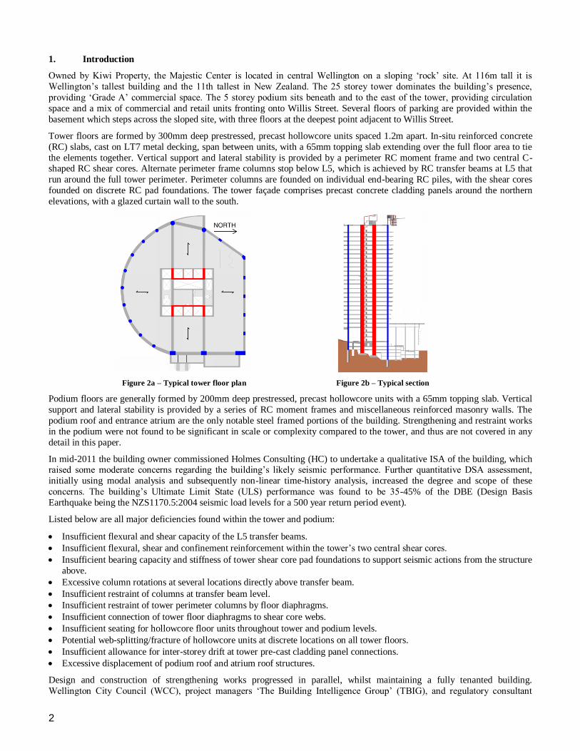
Tower floors are formed by 300mm deep prestressed, precast hollowcore units spaced 1.2m apart. In-situ reinforced concrete
(RC) slabs, cast on LT7 metal decking, span between units, with a 65mm topping slab extending over the full floor area to tie
the elements together. Vertical support and lateral stability is provided by a perimeter RC moment frame and two central C-shaped RC shear cores. Alternate perimeter frame columns stop below L5, which is achieved by RC transfer beams at L5 that
run around the full tower perimeter. Perimeter columns are founded on individual end-bearing RC piles, with the shear cores
founded on discrete RC pad foundations. The tower façade comprises precast concrete cladding panels around the northern
elevations, with a glazed curtain wall to the south.
Figure 2a – Typical tower floor plan Figure 2b – Typical section
Podium floors are generally formed by 200mm deep prestressed, precast hollowcore units with a 65mm topping slab. Vertical
support and lateral stability is provided by a series of RC moment frames and miscellaneous reinforced masonry walls. The
podium roof and entrance atrium are the only notable steel framed portions of the building. Strengthening and restraint works
in the podium were not found to be significant in scale or complexity compared to the tower, and thus are not covered in any
detail in this paper.
In mid-2011 the building owner commissioned Holmes Consulting (HC) to undertake a qualitative ISA of the building, which raised some moderate concerns regarding the building’s likely seismic performance. Further quantitative DSA assessment,
initially using modal analysis and subsequently non-linear time-history analysis, increased the degree and scope of these
concerns. The building’s Ultimate Limit State (ULS) performance was found to be 35-45% of the DBE (Design Basis
Earthquake being the NZS1170.5:2004 seismic load levels for a 500 year return period event).
Listed below are all major deficiencies found within the tower and podium:
Insufficient flexural and shear capacity of the L5 transfer beams.
Insufficient flexural, shear and confinement reinforcement within the tower’s two central shear cores.
Insufficient bearing capacity and stiffness of tower shear core pad foundations to support seismic actions from the structure
above.
Excessive column rotations at several locations directly above transfer beam.
Insufficient restraint of columns at transfer beam level.
Insufficient restraint of tower perimeter columns by floor diaphragms.
Insufficient connection of tower floor diaphragms to shear core webs.
Insufficient seating for hollowcore floor units throughout tower and podium levels.
Potential web-splitting/fracture of hollowcore units at discrete locations on all tower floors.
Insufficient allowance for inter-storey drift at tower pre-cast cladding panel connections.
Excessive displacement of podium roof and atrium roof structures.
Design and construction of strengthening works progressed in parallel, whilst maintaining a fully tenanted building.
Wellington City Council (WCC), project managers ‘The Building Intelligence Group’ (TBIG), and regulatory consultant
3
‘Holmes Farsight’ collaborated to achieve a compliance pathway for this process. Design of strengthening measures for the
tower commenced in early 2012 and concluded in late-2014, comprising the delivery of approximately 20 separate packages.
Construction commenced in late 2012 and concluded in late 2016. Fletcher Construction Company (FCC) were the main
contractor and pre-construction consultant. Following completion of the strengthening work, the building’s capacity has
increased to 100%DBE(ULS) and 150%DBE(CLS) levels as assessed to ASCE-41 performance objectives to Life Safety and
Collapse Prevention performance criteria respectively (American Society of Civil Engineers 2007). The assessment and
strengthening process was externally peer reviewed for regulatory and client risk mitigation purposes by Beca (2016a, 2016b).
2. Assessment Process
As part of the ISA it was noted that seismic loading requirements for a building of this type should have been marginally higher at the time of original design compared to current requirements. However, assuming moderate displacement ductility,
and apportioning the tower design base shear equally between the perimeter frame and central shear cores, suggested element
capacities would be exceeded at low load levels. All aspects of this process were noted to be highly approximate and further
study was recommended.
The initial DSA was on the basis of MRSA using the software ETABS. Above transfer beam level, the tower perimeter frame
was found to generally follow capacity design principles and have satisfactory detailing to exhibit a ductile response.
However, in at least one bay of the lobby level, transfer beam shear and flexural capacities were insufficient to sustain
serviceability gravity transfer loads (i.e. G+0.3Qu), thus undermining a ductile response in the frames above. The absence of
confinement reinforcement and low vertical reinforcement ratio (<0.5%) in the shear cores also suggested a brittle response.
Assuming a ‘nominally ductile’ displacement ductility capacity, shear core moment and shear capacities were in theory
approximately 65%DBE demands. However, there were doubts the computed capacities were valid due to the aforementioned
detailing issues. L5 transfer beam capacities were found to be exceeded in most bays at load levels below 33%DBE.
Behaviour of the dual system and the response of such ‘non-compliant’ elements was deemed too complex for MRSA to be
reliable. Instead a performance-based assessment utilizing non-linear time history analysis (NLTHA) was recommended.
The analysis engine ANSR-II (Mondkar and Powell 1979) and Holmes Consulting’s in-house processing software (Holmes
Consulting 2010) were used for the NLTHA. El Centro (1940), Hokkaido (2003) and Izmit (1999) ground motion records
were selected as the most appropriate (Oyarzo-Vera, McVerry, Ingham 2012) and scaled to the NZS 1170.5 spectra. Given the
site is close to the Wellington fault, at least one forward directivity record (Izmit) was required (NZS 1170.5:2004).
On-site inspection of the transfer beams revealed evidence of shear cracking and minor mid-span positive flexural hinging. It
was suspected that a significant portion of gravity transfer loads were being resisted by vierendeel action in the multiple
storeys of framing above the transfer beam. A NLTHA model with the transfer beam removed was subjected to gravity
loading and 33% DBE seismic loading. This verified vierendeel action could maintain stability, albeit with some damage, and
the building was therefore concluded to not be ‘earthquake prone’. All subsequent NLTHA assessment models assumed strengthening of the transfer beam had been carried out.
Describing the NLTHA based assessment in much further detail is beyond the scope of this paper. The primary benefit was
achieving an accurate performance-based assessment for each major structural component. More specifically toward the
design of strengthening measures, the benefits of NLTHA included an accurate time-dependent distribution of lateral load
between the perimeter frame and cores, an understanding of rotation and compression demands on the shear cores,
consideration of ‘shake down’ of perimeter column gravity loads onto the transfer beams, rotation and thus elongation of beam
hinges in the perimeter frame and upper-bound foundation demands.
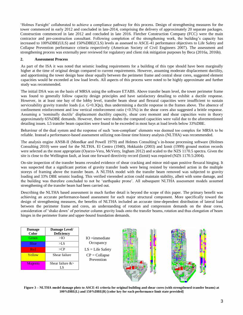
Damage
Color
Damage Level/
Deficiency
Green >IO IO =immediate
Occupancy Blue >LS
Red >CP LS = Life Safety
Yellow Shear failure CP = Collapse Prevention
Magenta Shear failure &> LS
Figure 3 – NLTHA model damage plots to ASCE-41 criteria for original building and shear cores (with strengthened transfer beams) at
100%DBE(L) and 150%DBE(R) [color key for each performance limit state provided]
4
Beyond NLTHA, further analysis was required to assess the particular effects in this building arising from inelastic elongation
in the perimeter framing. Frame elongation was assessed by determining the elongation expected from the potential plastic
hinges (Fenwick, Bull, Gardiner 2010) and replicating these by imposing temperatures on beam elements within a three
dimensional ‘line and node’ model of the structure, using the software Microstran.
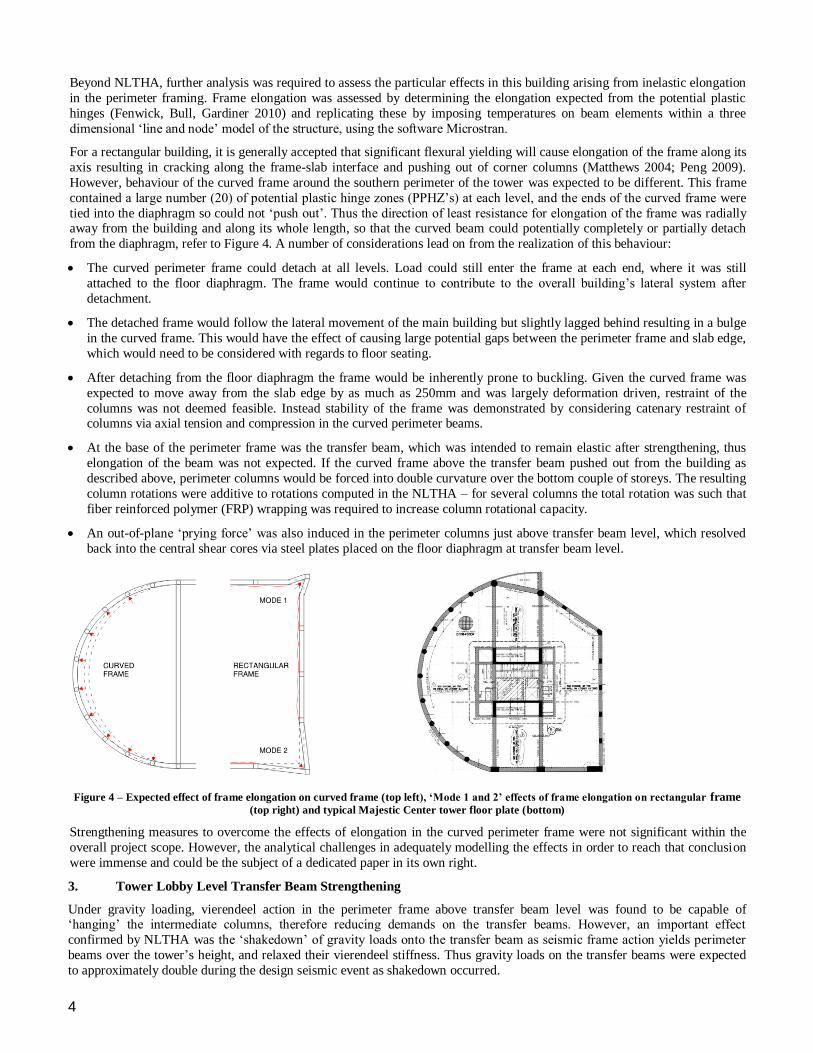
For a rectangular building, it is generally accepted that significant flexural yielding will cause elongation of the frame along its
axis resulting in cracking along the frame-slab interface and pushing out of corner columns (Matthews 2004; Peng 2009).
However, behaviour of the curved frame around the southern perimeter of the tower was expected to be different. This frame
contained a large number (20) of potential plastic hinge zones (PPHZ’s) at each level, and the ends of the curved frame were
tied into the diaphragm so could not ‘push out’. Thus the direction of least resistance for elongation of the frame was radially away from the building and along its whole length, so that the curved beam could potentially completely or partially detach
from the diaphragm, refer to Figure 4. A number of considerations lead on from the realization of this behaviour:
The curved perimeter frame could detach at all levels. Load could still enter the frame at each end, where it was still
attached to the floor diaphragm. The frame would continue to contribute to the overall building’s lateral system after
detachment.
The detached frame would follow the lateral movement of the main building but slightly lagged behind resulting in a bulge
in the curved frame. This would have the effect of causing large potential gaps between the perimeter frame and slab edge,
which would need to be considered with regards to floor seating.
After detaching from the floor diaphragm the frame would be inherently prone to buckling. Given the curved frame was
expected to move away from the slab edge by as much as 250mm and was largely deformation driven, restraint of the
columns was not deemed feasible. Instead stability of the frame was demonstrated by considering catenary restraint of columns via axial tension and compression in the curved perimeter beams.
At the base of the perimeter frame was the transfer beam, which was intended to remain elastic after strengthening, thus
elongation of the beam was not expected. If the curved frame above the transfer beam pushed out from the building as
described above, perimeter columns would be forced into double curvature over the bottom couple of storeys. The resulting
column rotations were additive to rotations computed in the NLTHA – for several columns the total rotation was such that
fiber reinforced polymer (FRP) wrapping was required to increase column rotational capacity.
An out-of-plane ‘prying force’ was also induced in the perimeter columns just above transfer beam level, which resolved
back into the central shear cores via steel plates placed on the floor diaphragm at transfer beam level.
Figure 4 – Expected effect of frame elongation on curved frame (top left), ‘Mode 1 and 2’ effects of frame elongation on rectangular frame (top right) and typical Majestic Center tower floor plate (bottom)
Strengthening measures to overcome the effects of elongation in the curved perimeter frame were not significant within the
overall project scope. However, the analytical challenges in adequately modelling the effects in order to reach that conclusion
were immense and could be the subject of a dedicated paper in its own right.
3. Tower Lobby Level Transfer Beam Strengthening
Under gravity loading, vierendeel action in the perimeter frame above transfer beam level was found to be capable of ‘hanging’ the intermediate columns, therefore reducing demands on the transfer beams. However, an important effect
confirmed by NLTHA was the ‘shakedown’ of gravity loads onto the transfer beam as seismic frame action yields perimeter
beams over the tower’s height, and relaxed their vierendeel stiffness. Thus gravity loads on the transfer beams were expected
to approximately double during the design seismic event as shakedown occurred.
5
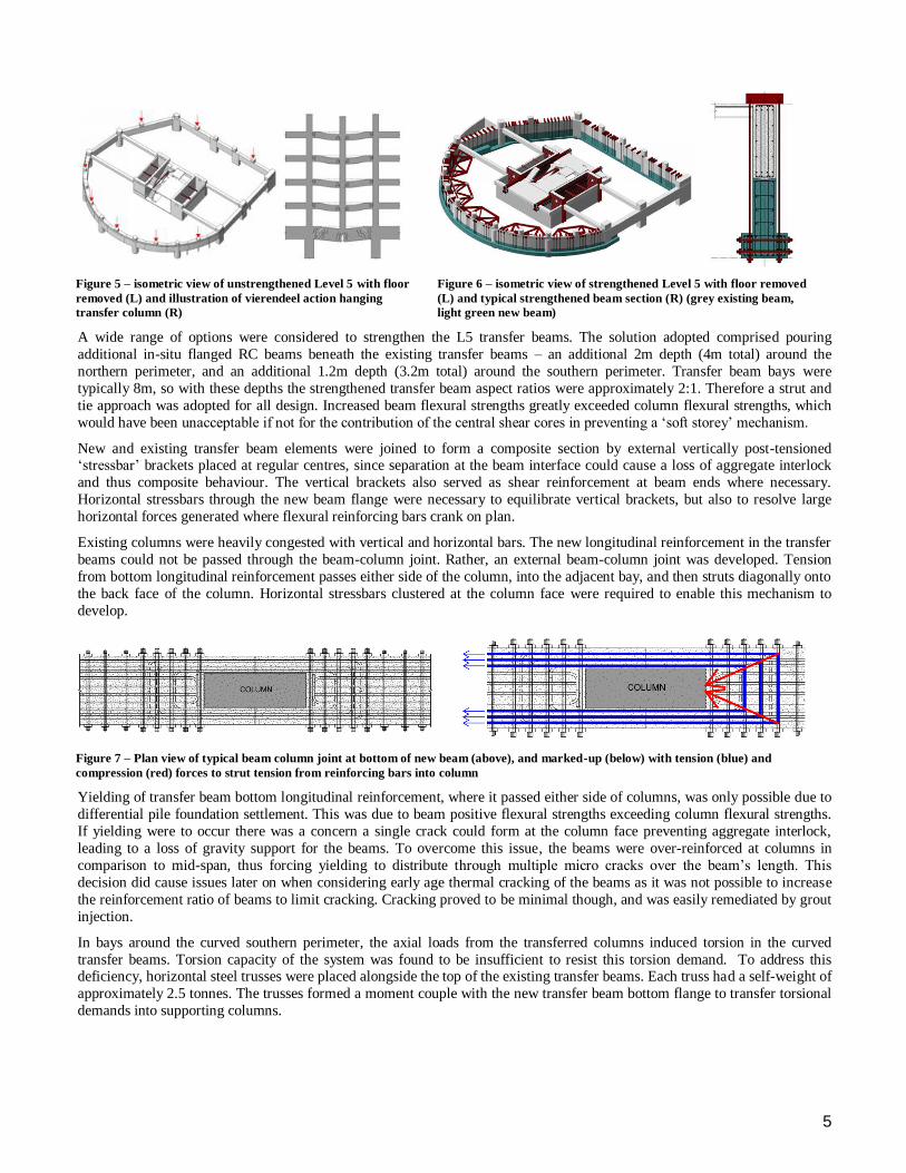
Figure 5 – isometric view of unstrengthened Level 5 with floor
removed (L) and illustration of vierendeel action hanging
transfer column (R)
Figure 6 – isometric view of strengthened Level 5 with floor removed
(L) and typical strengthened beam section (R) (grey existing beam,
light green new beam)
A wide range of options were considered to strengthen the L5 transfer beams. The solution adopted comprised pouring
additional in-situ flanged RC beams beneath the existing transfer beams – an additional 2m depth (4m total) around the
northern perimeter, and an additional 1.2m depth (3.2m total) around the southern perimeter. Transfer beam bays were
typically 8m, so with these depths the strengthened transfer beam aspect ratios were approximately 2:1. Therefore a strut and
tie approach was adopted for all design. Increased beam flexural strengths greatly exceeded column flexural strengths, which
would have been unacceptable if not for the contribution of the central shear cores in preventing a ‘soft storey’ mechanism.
New and existing transfer beam elements were joined to form a composite section by external vertically post-tensioned ‘stressbar’ brackets placed at regular centres, since separation at the beam interface could cause a loss of aggregate interlock
and thus composite behaviour. The vertical brackets also served as shear reinforcement at beam ends where necessary.
Horizontal stressbars through the new beam flange were necessary to equilibrate vertical brackets, but also to resolve large
horizontal forces generated where flexural reinforcing bars crank on plan.
Existing columns were heavily congested with vertical and horizontal bars. The new longitudinal reinforcement in the transfer
beams could not be passed through the beam-column joint. Rather, an external beam-column joint was developed. Tension
from bottom longitudinal reinforcement passes either side of the column, into the adjacent bay, and then struts diagonally onto
the back face of the column. Horizontal stressbars clustered at the column face were required to enable this mechanism to
develop.
Figure 7 – Plan view of typical beam column joint at bottom of new beam (above), and marked-up (below) with tension (blue) and
compression (red) forces to strut tension from reinforcing bars into column
Yielding of transfer beam bottom longitudinal reinforcement, where it passed either side of columns, was only possible due to
differential pile foundation settlement. This was due to beam positive flexural strengths exceeding column flexural strengths.
If yielding were to occur there was a concern a single crack could form at the column face preventing aggregate interlock,
leading to a loss of gravity support for the beams. To overcome this issue, the beams were over-reinforced at columns in
comparison to mid-span, thus forcing yielding to distribute through multiple micro cracks over the beam’s length. This
decision did cause issues later on when considering early age thermal cracking of the beams as it was not possible to increase
the reinforcement ratio of beams to limit cracking. Cracking proved to be minimal though, and was easily remediated by grout
injection.
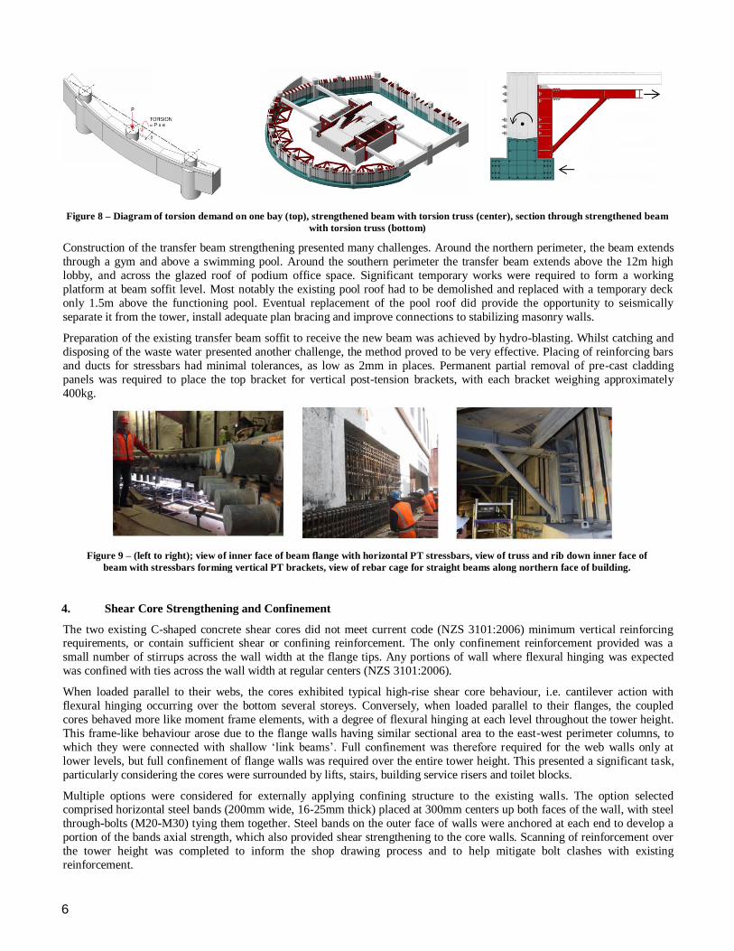
In bays around the curved southern perimeter, the axial loads from the transferred columns induced torsion in the curved
transfer beams. Torsion capacity of the system was found to be insufficient to resist this torsion demand. To address this deficiency, horizontal steel trusses were placed alongside the top of the existing transfer beams. Each truss had a self-weight of
approximately 2.5 tonnes. The trusses formed a moment couple with the new transfer beam bottom flange to transfer torsional
demands into supporting columns.
6
Figure 8 – Diagram of torsion demand on one bay (top), strengthened beam with torsion truss (center), section through strengthened beam
with torsion truss (bottom)
Construction of the transfer beam strengthening presented many challenges. Around the northern perimeter, the beam extends
through a gym and above a swimming pool. Around the southern perimeter the transfer beam extends above the 12m high
lobby, and across the glazed roof of podium office space. Significant temporary works were required to form a working
platform at beam soffit level. Most notably the existing pool roof had to be demolished and replaced with a temporary deck
only 1.5m above the functioning pool. Eventual replacement of the pool roof did provide the opportunity to seismically
separate it from the tower, install adequate plan bracing and improve connections to stabilizing masonry walls.
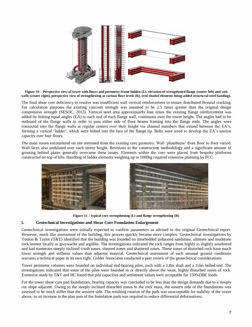
Preparation of the existing transfer beam soffit to receive the new beam was achieved by hydro-blasting. Whilst catching and
disposing of the waste water presented another challenge, the method proved to be very effective. Placing of reinforcing bars
and ducts for stressbars had minimal tolerances, as low as 2mm in places. Permanent partial removal of pre-cast cladding
panels was required to place the top bracket for vertical post-tension brackets, with each bracket weighing approximately
400kg.
Figure 9 – (left to right); view of inner face of beam flange with horizontal PT stressbars, view of truss and rib down inner face of
beam with stressbars forming vertical PT brackets, view of rebar cage for straight beams along northern face of building.
4. Shear Core Strengthening and Confinement
The two existing C-shaped concrete shear cores did not meet current code (NZS 3101:2006) minimum vertical reinforcing requirements, or contain sufficient shear or confining reinforcement. The only confinement reinforcement provided was a
small number of stirrups across the wall width at the flange tips. Any portions of wall where flexural hinging was expected
was confined with ties across the wall width at regular centers (NZS 3101:2006).
When loaded parallel to their webs, the cores exhibited typical high-rise shear core behaviour, i.e. cantilever action with
flexural hinging occurring over the bottom several storeys. Conversely, when loaded parallel to their flanges, the coupled
cores behaved more like moment frame elements, with a degree of flexural hinging at each level throughout the tower height.
This frame-like behaviour arose due to the flange walls having similar sectional area to the east-west perimeter columns, to
which they were connected with shallow ‘link beams’. Full confinement was therefore required for the web walls only at
lower levels, but full confinement of flange walls was required over the entire tower height. This presented a significant task,
particularly considering the cores were surrounded by lifts, stairs, building service risers and toilet blocks.
Multiple options were considered for externally applying confining structure to the existing walls. The option selected comprised horizontal steel bands (200mm wide, 16-25mm thick) placed at 300mm centers up both faces of the wall, with steel
through-bolts (M20-M30) tying them together. Steel bands on the outer face of walls were anchored at each end to develop a
portion of the bands axial strength, which also provided shear strengthening to the core walls. Scanning of reinforcement over
the tower height was completed to inform the shop drawing process and to help mitigate bolt clashes with existing
reinforcement.
7
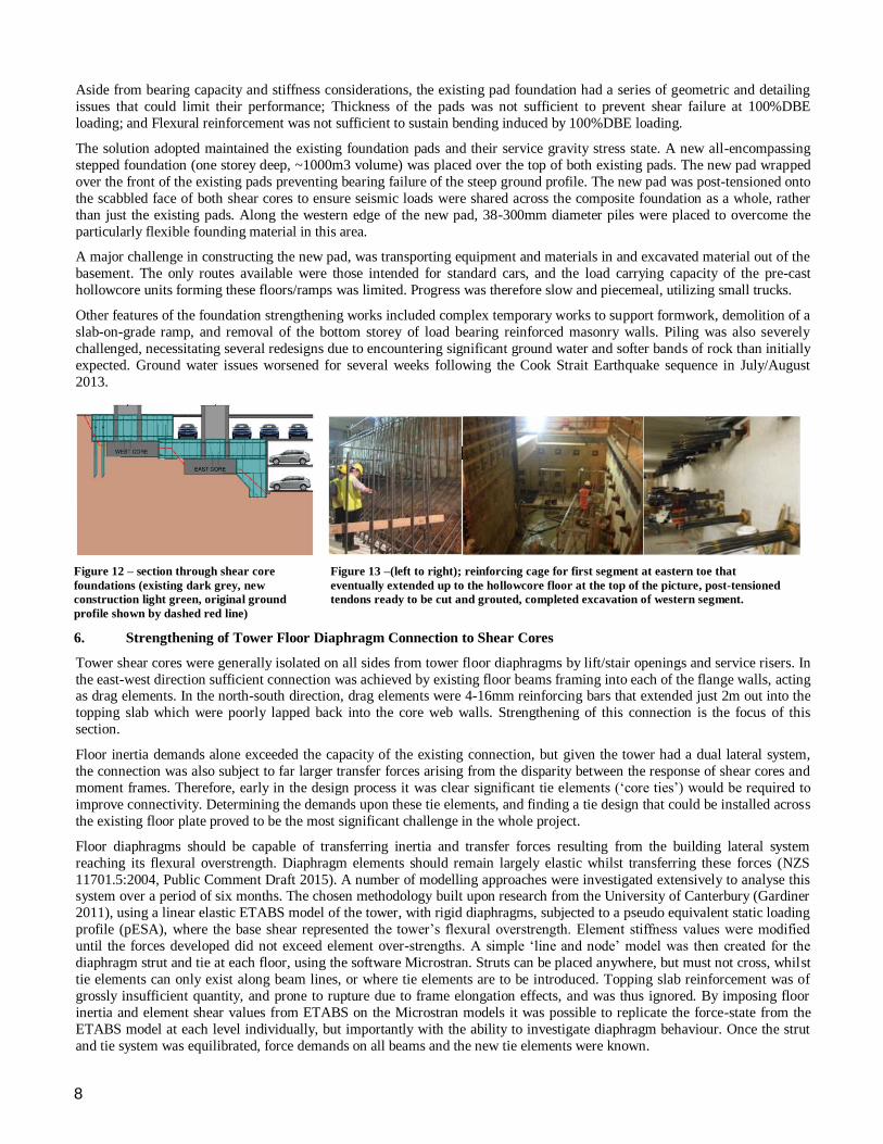
Figure 10 – Perspective view of tower with floors and perimeter frame hidden (L), elevation of strengthened flange (center left) and web
walls (center right), perspective view of strengthening at various floor levels (R), (red shaded elements being added structural steel banding).
The final shear core deficiency to resolve was insufficient wall vertical reinforcement to ensure distributed flexural cracking.
For calculation purposes the existing concrete strength was assumed to be 2.5 times greater than the original design
compressive strength (SESOC, 2012). Vertical steel area approximately four times the existing flange reinforcement was
added by bolting equal angles (EA) to each end of each flange wall, continuous over the tower height. The angles had to be
outboard of the flange walls in order to pass either side of floor beams framing into the flange ends. The angles were
connected into the flange walls at regular centers over their height via channel members that extend between the EA’s,
forming a vertical ‘ladder’, which were bolted into the face of the flange tip. Bolts were sized to develop the EA’s tension
capacity over four floors.
The main issues encountered on site stemmed from the existing core geometry. Wall ‘plumbness’ from floor to floor varied.
Wall faces also undulated over each storey height. Revisions to the construction methodology and a significant amount of
grouting behind plates generally overcame these issues. Elements within the core were placed from bespoke platforms constructed on-top of lifts. Handling of ladder elements weighing up to 1000kg required extensive planning by FCC.
Figure 11 – typical core strengthening (L) and flange strengthening (R)
5. Geotechnical Investigations and Shear Core Foundation Enlargement
Geotechnical investigations were initially expected to confirm parameters as advised in the original Geotechnical report.
However, much like assessment of the building, this process quickly became more complex. Geotechnical investigations by
Tonkin & Taylor (T&T) identified that the building was founded on interbedded indurated sandstone, siltstone and mudstone
rock known locally as greywacke and argillite. The investigations indicated the rock ranges from highly to slightly weathered and had numerous steeply inclined crush zones, sheared zones and shattered zones. These zones of disturbed rock have much
lower strength and stiffness values than adjacent material. Geotechnical assessment of such unusual ground conditions
warrants a technical paper in its own right. Golder Associates conducted a peer review of the geotechnical considerations.
Tower perimeter columns were founded on individual end-bearing piles, each with a 1.8m shaft and a 3.6m belled end. The
investigations indicated that some of the piles were founded in or directly above the weak, highly disturbed zones of rock.
Extensive study by T&T and HC found that pile capacities and settlement values were acceptable for 150%DBE loads.
For the tower shear core pad foundations, bearing capacity was concluded to be less than the design demands due to a steeply
cut slope adjacent. Owing to the steeply inclined disturbed zones in the rock mass, the eastern side of the foundations was
assessed to be much stiffer than the western side. The resulting rotation of the pads was unacceptable for stability of the tower
above, so an increase in the plan area of the foundation pads was required to reduce differential deformations.
8
Aside from bearing capacity and stiffness considerations, the existing pad foundation had a series of geometric and detailing
issues that could limit their performance; Thickness of the pads was not sufficient to prevent shear failure at 100%DBE
loading; and Flexural reinforcement was not sufficient to sustain bending induced by 100%DBE loading.
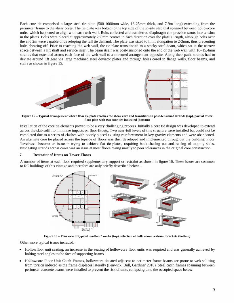
The solution adopted maintained the existing foundation pads and their service gravity stress state. A new all-encompassing
stepped foundation (one storey deep, ~1000m3 volume) was placed over the top of both existing pads. The new pad wrapped
over the front of the existing pads preventing bearing failure of the steep ground profile. The new pad was post-tensioned onto
the scabbled face of both shear cores to ensure seismic loads were shared across the composite foundation as a whole, rather
than just the existing pads. Along the western edge of the new pad, 38-300mm diameter piles were placed to overcome the
particularly flexible founding material in this area.
A major challenge in constructing the new pad, was transporting equipment and materials in and excavated material out of the
basement. The only routes available were those intended for standard cars, and the load carrying capacity of the pre-cast
hollowcore units forming these floors/ramps was limited. Progress was therefore slow and piecemeal, utilizing small trucks.
Other features of the foundation strengthening works included complex temporary works to support formwork, demolition of a
slab-on-grade ramp, and removal of the bottom storey of load bearing reinforced masonry walls. Piling was also severely
challenged, necessitating several redesigns due to encountering significant ground water and softer bands of rock than initially
expected. Ground water issues worsened for several weeks following the Cook Strait Earthquake sequence in July/August
2013.
Figure 12 – section through shear core
foundations (existing dark grey, new
construction light green, original ground
profile shown by dashed red line)
Figure 13 –(left to right); reinforcing cage for first segment at eastern toe that
eventually extended up to the hollowcore floor at the top of the picture, post-tensioned
tendons ready to be cut and grouted, completed excavation of western segment.
6. Strengthening of Tower Floor Diaphragm Connection to Shear Cores
Tower shear cores were generally isolated on all sides from tower floor diaphragms by lift/stair openings and service risers. In
the east-west direction sufficient connection was achieved by existing floor beams framing into each of the flange walls, acting as drag elements. In the north-south direction, drag elements were 4-16mm reinforcing bars that extended just 2m out into the
topping slab which were poorly lapped back into the core web walls. Strengthening of this connection is the focus of this
section.
Floor inertia demands alone exceeded the capacity of the existing connection, but given the tower had a dual lateral system,
the connection was also subject to far larger transfer forces arising from the disparity between the response of shear cores and
moment frames. Therefore, early in the design process it was clear significant tie elements (‘core ties’) would be required to
improve connectivity. Determining the demands upon these tie elements, and finding a tie design that could be installed across
the existing floor plate proved to be the most significant challenge in the whole project.
Floor diaphragms should be capable of transferring inertia and transfer forces resulting from the building lateral system
reaching its flexural overstrength. Diaphragm elements should remain largely elastic whilst transferring these forces (NZS
11701.5:2004, Public Comment Draft 2015). A number of modelling approaches were investigated extensively to analyse this system over a period of six months. The chosen methodology built upon research from the University of Canterbury (Gardiner
2011), using a linear elastic ETABS model of the tower, with rigid diaphragms, subjected to a pseudo equivalent static loading
profile (pESA), where the base shear represented the tower’s flexural overstrength. Element stiffness values were modified
until the forces developed did not exceed element over-strengths. A simple ‘line and node’ model was then created for the
diaphragm strut and tie at each floor, using the software Microstran. Struts can be placed anywhere, but must not cross, whilst
tie elements can only exist along beam lines, or where tie elements are to be introduced. Topping slab reinforcement was of
grossly insufficient quantity, and prone to rupture due to frame elongation effects, and was thus ignored. By imposing floor
inertia and element shear values from ETABS on the Microstran models it was possible to replicate the force-state from the
ETABS model at each level individually, but importantly with the ability to investigate diaphragm behaviour. Once the strut
and tie system was equilibrated, force demands on all beams and the new tie elements were known.
9
Each core tie comprised a large steel tie plate (500-1000mm wide, 16-25mm thick, and 7-9m long) extending from the
perimeter frame to the shear cores. The tie plate was bolted to the top side of the in-situ slab that spanned between hollowcore
units, which happened to align with each web wall. Bolts collected and transferred diaphragm compression struts into tension
in the plates. Bolts were placed at approximately 250mm centres in each direction over the plate’s length, although bolts over
the end 2m were capable of developing the full tie demand. The plate was sized to limit elongation to 2-3mm, thus preventing
bolts shearing off. Prior to reaching the web wall, the tie plate transitioned to a stocky steel beam, which sat in the narrow
space between a lift shaft and service riser. The beam itself was post-tensioned onto the end of the web wall with 16–15.4mm
strands that extended across each face of the web wall to a mirrored arrangement opposite. Along their path, strands had to
deviate around lift gear via large machined steel deviator plates and through holes cored in flange walls, floor beams, and stairs as shown in figure 15.
Figure 15 – Typical arrangement where floor tie plate reaches the shear core and transitions to post-tensioned strands (top), partial tower
floor plan with two core ties indicated (bottom)
Installation of the core tie elements proved to be a very challenging process. Initially a core tie design was developed to extend
across the slab soffit to minimise impacts on floor fitouts. Two near-full levels of this structure were installed but could not be
completed due to a series of clashes with poorly placed existing reinforcement in key gravity elements and were abandoned.
An alternate core tie placed across the topside of floors was then developed and implemented throughout the building. Floor
‘levelness’ became an issue in trying to achieve flat tie plates, requiring both chasing out and raising of topping slabs.
Navigating strands across cores was an issue at most floors owing mostly to poor tolerances in the original core construction.
7. Restraint of Items on Tower Floors
A number of items at each floor required supplementary support or restraint as shown in figure 16. These issues are common
to RC buildings of this vintage and therefore are only briefly described below. .
Figure 16 – Plan view of typical ‘on-floor’ works (top), selection of hollowcore restraint brackets (bottom)
Other more typical issues included:
Hollowfloor unit seating, an increase in the seating of hollowcore floor units was required and was generally achieved by
bolting steel angles to the face of supporting beams.
Hollowcore Floor Unit Catch Frames, hollowcore situated adjacent to perimeter frame beams are prone to web splitting from torsion induced as the frame displaces laterally (Fenwick, Bull, Gardiner 2010). Steel catch frames spanning between
perimeter concrete beams were installed to prevent the risk of units collapsing onto the occupied space below.
10
Perimeter Columns to the North/ North-West Elevation had insufficient restraint, therefore steel tie plates (‘column ties’)
were provided. The greater of 5% of the column axial load and the frame and façade inertia load was considered for the
design.
Restraint of Pre-Cast Cladding Panels, a catch bracket system was installed to prevent panels falling from the building
following damage to existing connections which were not detailed to accommodate large inter-storey drifts.
8. Conclusions
Undertaking the seismic strengthening of the Majestic Centre has been a greater challenge technically, logistically and
financially than anyone expected. Despite that, the project has succeeded in significantly reducing the earthquake risk posed by the building to its occupants and the wider Wellington CBD. It has also spurred the development of new and improved
methods of assessment and remediation for buildings of this type.
Lastly, it has hopefully served to demonstrate that seismic strengthening, of large commercial buildings ‘in-service’ is possible
provided owners, designers, contractors, regulators and tenants are willing to work together.
9. References
American Society of Civil Engineers, Seismic Rehabilitation of Existing Buildings ASCE41, Virginia, USA, 2007
Beca, Majestic Center – Letter dated 8 March 2016: Results of Peer Review of Seismic Strengthening Scheme,
Correspondence, 2016
Beca, Producer Statement – PS2 – Design Review, March 2016
Fenwick R. C., Bull D., Gardiner D., Assessment of Hollowcore Floors for Seismic Performance, University of Canterbury,
Civil and Natural Resources Research Report, 2010.
Gardiner, D., Design Recommendations and Methods for Reinforced Concrete Floor Diaphragms Subjected to Seismic
Forces, PhD Thesis, University of Canterbury, 2011
Holmes Consulting, Performance Based Evaluation of Existing Buildings: Reference Manual. Revision 7, September 2010.
Kiwi Income Property Trust, Annual Report 2013
Matthews, J. G., Hollowcore floor slab performance following a severe earthquake, PhD Thesis, University of Canterbury,
2004
Mondkar, D.P. and Powell, G.H., ANSR II Analysis of Non-linear Structural Response User's Manual, EERC 79/17,
University of California, Berkeley, July 1979
New Zealand Government, Building Act 2004
Oyarzo-Vera, C. A, McVerry, G. H., Ingham, J. M., Seismic Zonation and Default Suite of Ground-Motion Records for Time-
History Analysis in the North Island of New Zealand, Earthquake Spectra, Vol 28, May 2012
Peng B.H.H., Seismic Performance Assessment of Reinforced Concrete Buildings with Pre-cast Concrete Floor Systems, PhD Thesis, University of Canterbury, 2009.
Standards New Zealand, Concrete Structures Standard – New Zealand, NZS 3101:2006
Standards New Zealand, Structural Design Actions Part 5: Earthquake Actions – New Zealand, NZS 1170.5:2004
Standards New Zealand, Structural Design Actions Part 5: Earthquake Actions – New Zealand, NZS 1170.5:2004 – Public
Comment Draft, March 2015
Structural Engineering Society New Zealand (SESOC), Interim Design Guidance 0.8, September 2012
i J.G. White, Holmes Consulting, Netherlands. Email: [email protected] ii H.S. McKenzie, Holmes Consulting, Wellington. Email: [email protected] iii A.E. Philpott, Holmes Consulting, Wellington. Email: [email protected] iv D.K. Bull, Holmes Consulting, Christchurch, College of Engineering, University of Canterbury, Christchurch. Email:
[email protected] v B.D Galloway, Holmes Consulting, Christchurch. Email: [email protected] vi R. van Ballegooy, Holmes Consulting, Auckland. Email: [email protected]