Seguridad de BT
16
SAUDI STANDARD SASO IEC 61557-1/2010 SASO IEC 61557-1/2009 ELECTRICAL SAFETY IN LOW VOLTAGE DISTRIBUTION SYSTEMS UP TO 1 000 V a.c. AND 1 500 V d.c. – EQUIPMENT FOR TESTING, MEASURING OR MONITORING OF PROTECTIVE MEASURES – Part 1: General requirements SAUDI ARABIAN STANDARDS ORGANIZATION THIS DOCUMENT IS A DRAFT SAUDI STANDARD CIRCULATED FOR COMMENT. IT IS, THEREFORE SUBJECT TO CHANGE AND MAY NOT BE REFERRED TO AS A SAUDI STANDARD UNTIL APPROVED BY THE BOARD OF DIRECTORS.
-
Upload
daniel-rizzo -
Category
Documents
-
view
22 -
download
2
Transcript of Seguridad de BT
SAUDI STANDARD SASO IEC 61557-1/2010
SASO IEC 61557-1/2009
ELECTRICAL SAFETY IN LOW VOLTAGE DISTRIBUTION SYSTEMS UP TO 1 000 V a.c. AND 1 500 V d.c. –
EQUIPMENT FOR TESTING, MEASURING OR MONITORING OF PROTECTIVE MEASURES –
Part 1: General requirements
SAUDI ARABIAN STANDARDS ORGANIZATION
THIS DOCUMENT IS A DRAFT SAUDI STANDARD CIRCULATED FOR COMMENT. IT IS, THEREFORE SUBJECT TO CHANGE AND MAY NOT BE REFERRED TO AS A SAUDI STANDARD UNTIL APPROVED BY THE BOARD OF DIRECTORS.
SAUDI STANDARD SASO IEC 61557-1/2010
1
CONTENTS
FOREWORD ............................................................................ فة! خطأ .اإلشارة المرجعیة غیر معّر INTRODUCTION ....................................................................... فة! خطأ .اإلشارة المرجعیة غیر معّر 1 Scope ..................................................................................................................... 3 2 Normative references ............................................................................................... 3 3 Terms and definitions ............................................................................................... 5 4 Requirements .......................................................................................................... 9
4.1 Operating uncertainty (B), percentage operating uncertainty (B [%]) .................. 10 4.2 Rated operating conditions ............................................................................. 11 4.3 Battery check facility ..................................................................................... 11 4.4 Terminals ...................................................................................................... 11 4.5 Class of protection ......................................................................................... 11 4.6 Class of pollution ........................................................................................... 11 4.7 Overvoltage category..................................................................................... 11 4.8 Measuring category ....................................................................................... 11 4.9 Electromagnetic compatibility ......................................................................... 12 4.10 Vibration test ................................................................................................. 12
5 Marking and operating instructions .......................................................................... 12 5.1 Marking ........................................................................................................ 12 5.2 Operating instructions .................................................................................... 13
6 Tests ..................................................................................................................... 13 6.1 Inf luence of position ...................................................................................... 13 6.2 Inf luence of temperature ................................................................................ 13 6.3 Inf luence of the supply voltage ....................................................................... 14 6.4 Battery check facility ..................................................................................... 14 6.5 Protection class ............................................................................................. 14 6.6 Terminals ...................................................................................................... 14 6.7 Mechanical requirements ............................................................................... 14 6.8 Marking and operating instructions .................................................................. 14
Bibliography ................................................................................................................ 15
SAUDI STANDARD SASO IEC 61557-1/2010
2
Foreword
The Saudi Arabian Standards Organization (SASO) has adopted the International standard No. IEC 61557-1/2007 “ELECTRICAL SAFETY IN LOW VOLTAGE DISTRIBUTION SYSTEMS UP TO 1 000 V a.c. AND 1 500 V d.c. – EQUIPMENT FOR TESTING, MEASURING OR MONITORING OF PROTECTIVE MEASURES – Part 1: General requirements ”. The text of this international standard has been translated into Arabic so as to be approved as a Saudi standard without introducing any technical modification.

SAUDI STANDARD SASO IEC 61557-1/2010
3
ELECTRICAL SAFETY IN LOW VOLTAGE DISTRIBUTION SYSTEMS
UP TO 1 000 V a.c. AND 1 500 V d.c. – EQUIPMENT FOR TESTING, MEASURING OR MONITORING OF
PROTECTIVE MEASURES –
Part 1: General requirements
1 Scope
This part of IEC 61557 specif ies the general requirements for measuring and monitoring equipment for testing the electrical safety in low voltage distribution systems with nominal voltages up to 1 000 V a.c. and 1 500 V d.c.
When measuring equipment or measuring installations involve measurement tasks of various measuring equipment covered by this series of standards, then the part of this series of standards relevant to each of the measurement tasks is applicable.
NOTE The term "measuring equipment" will hereafter be used to designate "testing, measuring and monitoring equipment".
2 Normative references
The following referenced documents are indispensable for the application of this document. For dated references, only the edition cited applies. For undated references, the latest edition of the referenced document (including any amendments) applies.
IEC 60038:1983 1), IEC standard voltages
Amendment 1: 1994 Amendment 2: 1997
IEC 60364-6:2006, Electrical installations of buildings – Part 6: Verification
IEC 60664-1, Insulation coordination for equipment within low-voltage systems - Part 1: Principles, requirements and tests
IEC 60529: 2001, Degrees of protection provided by enclosures (IP code)
IEC 61010-1:2001, Safety requirements for electrical equipment for measurement, control and laboratory use – Part 1: General requirements
IEC 61010-2-030, Safety requirements for electrical equipment for measurement, control, and laboratory use – Part 2-030: Special requirements for testing and measuring circuits 2)
IEC 61326-2-2:2005, Electrical equipment for measurement, control and laboratory use – EMC requirements – Part 2-2: Particular requirements – Test configurations, operational
–––––––– 1) There exists a consolidated edition (6.2), which includes IEC 60038:1983 and its Amendments 1 (1994) and 2
(1997).
2) To be published.

SAUDI STANDARD SASO IEC 61557-1/2010
4
conditions and performance criteria for portable test, measuring and monitoring equipment used in low-voltage distribution systems
SAUDI STANDARD SASO IEC 61557-1/2010
5
IEC 61326-2-4:2006, Electrical equipment for measurement, control and laboratory use, - EMC requirements - Part 2: Particular requirements – Test configurations, operational conditions and performance criteria for insulation monitoring devices according to IEC 61557-8 and for equipment for insulation fault location according to IEC 61557-9
IEC 61557-2, Electrical safety in low voltage distribution systems up to 1000 V a.c. and 1500 V d.c. – Equipment for testing, measuring or monitoring of protective measures – Part 2: Insulation resistance
IEC 61557-3, Electrical safety in low voltage distribution systems up to 1000 V a.c. and 1500 V d.c. – Equipment for testing, measuring or monitoring of protective measures – Part 3: Loop impedance
IEC 61557-4, Electrical safety in low voltage distribution systems up to 1000 V a.c. and 1500 V d.c. – Equipment for testing, measuring or monitoring of protective measures – Part 4: Resistance of earth connection and equipotential bonding
IEC 61557-5, Electrical safety in low voltage distribution systems up to 1000 V a.c. and 1500 V d.c. – Equipment for testing, measuring or monitoring of protective measures – Part 5: Resistance to earth
IEC 61557-6, Electrical safety in low voltage distribution systems up to 1000 V a.c. and 1500 V d.c. – Equipment for testing, measuring or monitoring of protective measures – Part 6: Residual current devices (RCD) in TT and TN systems
IEC 61557-7, Electrical safety in low voltage distribution systems up to 1000 V a.c. and 1500 V d.c. – Equipment for testing, measuring or monitoring of protective measures – Part 7: Phase sequence
IEC 61557-8, Electrical safety in low voltage distribution systems up to 1000 V a.c. and 1500 V d.c. – Equipment for testing, measuring or monitoring of protective measures – Part 8: Insulation monitoring devices for IT systems
IEC 61557-9, Electrical safety in low voltage distribution systems up to 1000 V a.c. and 1500 V d.c. – Equipment for testing, measuring or monitoring of protective measures – Part 9: Equipment for insulation fault location in IT systems
IEC 61557-10, Electrical safety in low voltage distribution systems up to 1000 V a.c. and 1500 V d.c. – Equipment for testing, measuring or monitoring of protective measures – Part 10: Combined measuring equipment for testing, measuring or monitoring of protective measures
3 Terms and definitions
For the purposes of this document, the following definitions apply.
3.1 nominal voltage of the distribution system (Un) voltage by which a distribution system or equipment is designated and to which certain operating characteristics are referred
[IEC 60038, Clause 1, modif ied]
SAUDI STANDARD SASO IEC 61557-1/2010
6
3.2 operating voltage in a system the value of the voltage under normal conditions, at a given instant and a given point of the system
[IEV 601-01-22, modif ied]
3.3 voltage against earth Uo a) in distribution systems with an earthed neutral point, the voltage between a phase conductor and the earthed neutral point;
b) in all other distribution systems, the voltage present between the remaining phase conductors and earth when one of the phase conductors is shorted to earth
3.4 fault voltage Uf voltage appearing under fault conditions between exposed conductive parts (and/or extraneous conductive parts) and earth
3.5 (effective) touch voltage Ut voltage between conductive parts when touched simultaneously by a person or an animal
[IEV 826-11-05]
3.6 conventional touch voltage limit UL maximum value of the touch voltage which is permitted to be maintained indefinitely in specif ied conditions of external inf luences and is usually equal to 50 V a.c., r.m.s. or 120 V ripple free d.c.
[IEV 826-02-04, modif ied]
3.7 rated range of voltages voltage range for which the measuring and monitoring equipment is intended to be used and for which it has been designed
3.8 rated supply voltage US voltage at a point where the measuring equipment does or can accept electric energy as a supply
3.9 output voltage Ua voltage across the measuring equipment terminals where this equipment does or can output electric energy

SAUDI STANDARD SASO IEC 61557-1/2010
7
3.10 open-circuit voltage Uq voltage present across unloaded terminals on the measuring equipment
3.11 rated voltage of measuring equipment UME voltage for which the measuring equipment is intended to be used and the value of which is marked on the equipment
3.12 extraneous voltage voltage to which the measuring equipment can be subjected by external inf luences. This is not required for the operation of the measuring equipment, but can interfere with its operation
3.13 rated current IN current of the measuring equipment under rated conditions
3.14 short-circuit current Ik current f lowing across the short-circuited terminals of the measuring equipment
3.15 rated frequency fN frequency for which the measuring equipment is intended to be used and designed
3.16 earth the conductive mass of the earth whose electric potential at any point is conventionally taken as equal to zero [IEV 826-04-01]
3.17 earth electrode a conductive part or group of conductive parts in intimate contact with and prov iding an electrical connection with earth [IEV 826-04-02]
3.18 total earthing resistance RA the resistance between the main earthing terminal and the earth [IEV 826-04-03]
3.19 percentage fiducial uncertainty (absolute) uncertainty of measuring equipment expressed as a percentage of the f iducial value (see 3.26)

SAUDI STANDARD SASO IEC 61557-1/2010
8
3.20 intrinsic uncertainty the uncertainty of a measuring instrument or supply instrument when used under reference conditions
[IEC 60359, definition 3.2.10]
NOTE The uncertainty caused by friction is part of the intrinsic uncertainty.
3.21 operating instrumental uncertainty instrumental uncertainty under the rated operating conditions
[IEC 60359, definition 3.2.11]
NOTE The operating uncertainty will have an extreme value (without regard to sign) at some combination of values of inf luence quantities within their operating ranges.
3.22 percentage operating uncertainty operating uncertainty of measuring equipment expressed as a percentage of the f iducial value
3.23 performance characteristic one of the quantities (described by values, tolerances, ranges) assigned to an equipment in order to define its performance
NOTE Depending on its application, one and the same quantity may be referred to in this standard as a "performance characteristic" and as a "measured or supplied quantity" and also may act as an "inf luence quantity".
In addition, the term "performance characteristic" includes quotients of quantities, such as voltage per unit of length.
3.24 influence quantity quantity which is not the subject of the measurement and whose change affects the realationship between the indication and the result of the measurement
[IEC 60359, definition 3.1.14]
NOTE An inf luence quantity may be external or internal with reference to the equipment. W hen the value of one of the inf luence quantities changes within its measuring range, it may affect the uncertainty due to another. The measured quantity or a parameter of it may itself act as an inf luence quantity. For example, for a voltmeter the value of the measured voltage may produce an additional uncertainty due to non-linearity or its frequency may also cause an additional uncertainty.
3.25 variation (due to an influence quantity) difference between the indicated values for the same value of the measurand of an indicating instrument, or the values of a material measure, when an influence quantity assumes, successively, two different values
[IEC 60359, definition 3.3.5]
3.26 fiducial value clearly specif ied value to which reference is made in order to define the f iducial uncertainty
NOTE This value can be, for example, the upper limit of the measuring range, the scalelength or any other value which is clearly stated
[IEV 311-01-16, modif ied]
SAUDI STANDARD SASO IEC 61557-1/2010
9
3.27 reference conditions appropriate set of specif ied values and/or ranges of values of inf luence quantities under which the smallest permissible uncertainties of a measuring instrument are specif ied
[IEC 60359, definition 3.3.10]
3.28 specified operating range range of values of a single influence quantity which forms a part of the rated operating conditions (see 3.31)
3.29 effect of the supply voltage effect inf luencing the functioning of measuring equipment, and consequently the measured value produced by it
3.30 effects of the distribution system voltage effect inf luencing the operation and, consequently, the measured value produced by it
3.31 rated operating conditions set of conditions that must be fulf illed during the measurement in order that a calibration diagram may be valid
[IEC 60359, definition 3.3.13]
3.32 rated measuring voltage UM voltage present at the measuring terminals during the measurement
4 Requirements
Measuring equipment, when used for a designated purpose, shall not endanger persons, livestock or property. Furthermore, measuring equipment with additional functions not forming part of the application of the IEC 61557 series, shall also not endanger persons, livestock or property.
Measuring equipment shall comply with IEC 61010-1 prov ided nothing to the contrary is specif ied hereafter.
If the measuring equipment indicates the voltage conditions at its measuring terminals, it must also indicate if the system voltage exists and if the live conductor is exchanged with the protective conductor.
SAUDI STANDARD SASO IEC 61557-1/2010
10
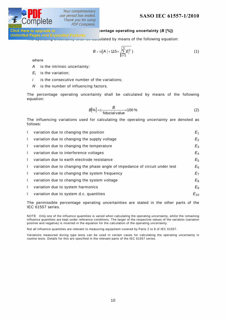
4.1 Operating uncertainty (B), percentage operating uncertainty (B [%])
The operating uncertainty shall be calculated by means of the following equation:
)15,1(1
2∑=
= ×+±N
iiEAB (1)
where A is the intrinsic uncertainty;
E i is the variation;
i is the consecutive number of the variations;
N is the number of inf luencing factors.
The percentage operating uncertainty shall be calculated by means of the following equation:
[ ] % 100value fiducial
% ×±=BB (2)
The influencing variations used for calculating the operating uncertainty are denoted as follows:
– variation due to changing the position E1
– variation due to changing the supply voltage E2
– variation due to changing the temperature E3
– variation due to interference voltages E4
– variation due to earth electrode resistance E5
– variation due to changing the phase angle of impedance of circuit under test E6
– variation due to changing the system frequency E7
– variation due to changing the system voltage E8
– variation due to system harmonics E9
– variation due to system d.c. quantities E10
The permissible percentage operating uncertainties are stated in the other parts of the IEC 61557 series.
NOTE Only one of the inf luence quantities is varied when calculating the operating uncertainty, whilst the remaining inf luence quantities are kept under reference conditions. The larger of the respective values of the variation (variation positive and negative) is inserted in the equation for the calculation of the operating uncertainty.
Not all inf luence quantities are relevant to measuring equipment covered by Parts 2 to 8 of IEC 61557.
Variations measured during type tests can be used in certain cases for calculating the operating uncertainty in routine tests. Details for this are specif ied in the relevant parts of the IEC 61557 series.
SAUDI STANDARD SASO IEC 61557-1/2010
11
4.2 Rated operating conditions
The stated operating uncertainties shall apply under the following rated operating conditions:
– temperature range from 0 °C to 35 °C; – a position of ±90° from the reference position for portable measuring equipment; – 85 % to 110 % of the nominal supply voltage for supply from the distribution systems (if
applicable). The values in IEC 60038 shall be used for a supply from the distribution system;
– the charge condition in accordance with 4.3 shall apply to the battery or batteries/ accumulators for measuring equipment with a supply from batteries/accumulators;
– the range of revolutions per minute stated by the manufacturer for measuring equipment with a supply from a hand-driven generator;
– frequency of the supply voltage ±1 % (if applicable).
NOTE Additional rated operating conditions are stated in other parts of the IEC 61557 series.
4.3 Battery check facility
Measuring equipment with power supplied from dry or rechargeable cells shall check that the state of charge of these batteries will permit measurement with specif ication. This may be done automatically as part of the measurement cycle or as a separate function. The battery should be loaded at least as heavily as during a measurement.
4.4 Terminals
The terminals shall be designed so that the probe assembly can be connected to the measuring equipment reliably and accidental touching of any live parts is impossible.
In this instance, the protective conductor shall be treated as a live part, with the exception of measuring devices covered in IEC 61557-8.
4.5 Class of protection
Measuring equipment shall be designed with double or reinforced insulation (protection class II), with the exception of measuring devices covered in IEC 61557-8 and IEC 61557-9.
4.6 Class of pollution
Measuring equipment shall be designed for at least pollution class 2 in accordance with IEC 61010-1.
4.7 Overvoltage category
Measuring equipment covered by IEC 61557-8 and IEC 61557-9 shall be designed for at least overvoltage category III according to IEC 60664-1.
4.8 Measuring category
Measuring equipment covered by IEC 61557-3, IEC 61557-5, IEC 61557-6, IEC 61557-7 and IEC 61557-10 shall be designed for at least measuring category III according IEC 61010-2-030. Measuring equipment covered by IEC 61557-2, IEC 61557-4, IEC 61557-5 (battery powered) and IEC 61557-4 shall be designed for at least measuring category II.
SAUDI STANDARD SASO IEC 61557-1/2010
12
4.9 Electromagnetic compatibility
4.9.1 Measuring equipment covered by IEC 61557-2, IEC 61557-3, IEC 61557-4, IEC 61557-5, IEC 61557-6, IEC 61557-7 and IEC 61557-10 shall be designed according to IEC 61326-2-2.
4.9.2 Measuring equipment covered by IEC 61557-8 and IEC 61557-9 shall be designed according to IEC 61326-2-4.
4.10 Vibration test
In addition to the mechanical resistance tests in accordance with IEC 61010-1, measuring equipment shall successfully pass the following v ibration conditions (type test):
– direction: three mutually perpendicular axes; – amplitude: 1 mm; – frequency: 25 Hz; – duration: 20 min.
5 Marking and operating instructions
Marking and operating instructions shall comply with IEC 61010-1 unless otherwise specif ied in other parts of IEC 61557.
5.1 Marking
The measuring equipment shall carry the following marking which shall be clearly readable and indelible.
5.1.1 Type of equipment.
5.1.2 Units of the measured quantity.
5.1.3 Ranges of measurement.
5.1.4 Type and current rating of the fuse in the case of exchangeable fuses.
5.1.5 Type of battery/accumulator and polarity of connection in the battery compartment.
5.1.6 Nominal voltage of the distribution system and the symbol for double insulation in accordance with IEC 61010-1 for measuring equipment with distribution system power supply.
5.1.7 Manufacturer’s name or registered trade mark.
5.1.8 Model number, name or other means to identify the equipment (inside or outside).
5.1.9 Reference to the operating instructions with the symbol ! in accordance with IEC 61010-1.
SAUDI STANDARD SASO IEC 61557-1/2010
13
5.2 Operating instructions The operating uncertainty, the intrinsic uncertainty and the variations E1 to E10 shall be prov ided in the operating instructions (with the exception of measuring devices covered by IEC 61557-8 and IEC 61557-9). In addition the operating instructions shall comprise the following details:
5.2.1 Connection diagrams.
5.2.2 Instructions for measurements.
5.2.3 Brief description of the principle of measurement.
5.2.4 Diagrams or tables showing the maximum permissible indicated values taking into consideration the tolerances stated by the manufacturer (if necessary).
5.2.5 Type of battery/rechargeable cells.
5.2.6 Information on the charging current, charging voltage and duration of charging for rechargeable cells.
5.2.7 Operational lifetime/runtime of the battery/rechargeable cells or the possible number of measurements.
5.2.8 Type of IP protection (IEC 60529).
5.2.9 Any necessary special guidance notes.
6 Tests
Measuring equipment shall be tested in accordance with IEC 61010-2-030 and IEC 61326-2-2 unless otherwise specif ied in the following subclauses or in other parts of IEC 61557 series.
All tests shall be carried out under reference conditions unless otherwise specif ied. The reference conditions are stated in the various parts of IEC 61557 series.
6.1 Influence of position
The variation E1 due to changing the position in accordance with 4.2, if applicable, shall be determined for positions +90° or –90° from the reference position stated by the manufacturer (routine test).
6.2 Influence of temperature
The variation E3 due to changing the temperature in accordance with 4.2 shall be determined under the following rated operating conditions:
– at 0 °C and 35 °C after reaching a state of equilibrium (type test).
SAUDI STANDARD SASO IEC 61557-1/2010
14
6.3 Influence of the supply voltage
The variation E2 due to changing the supply voltage shall be determined under the following rated operating conditions (routine test):
– limits in accordance with 4.2 for measuring equipment supplied from distribution systems;
– limits in accordance with 4.3 and 6.4 for measuring equipment supplied from a battery/accumulator;
– limits in accordance with 4.2 for measuring equipment supplied by a hand-driven generator.
6.4 Battery check facility
The lower and upper limits for the battery voltage to which the battery check facility in accordance with 4.3 is set, shall be determined by means of an external voltage source. These values shall be used during the test in accordance with 6.3 as limits for variation E2 by changing the supply voltage (routine test).
6.5 Protection class
Compliance with double or reinforced insulation (protection class II) in accordance with 4.5 shall be checked, with the exception of measuring devices covered by IEC 61557-8 and IEC 61557-9 (type test).
6.6 Terminals
Terminals in accordance with 4.4 shall be checked for protection against accidental contact with live parts (type test).
6.7 Mechanical requirements
The test shall be executed in accordance with 4.9 (type test).
The tests are deemed to have been passed successfully when no parts have become loose or bent and the connecting leads are not damaged. After the process, the measuring equipment shall comply with the requirements with respect to operating uncertainty in accordance with 4.1 (type test).
6.8 Marking and operating instructions
The marking and the operating instructions in accordance with Clause 5 of Parts 1 to 10 of the IEC 61557 series shall be checked by v isual inspection (type test, except correct marking as routine test).
SAUDI STANDARD SASO IEC 61557-1/2010
15
Bibliography
IEC 60050-300:2001, International Electrotechnical Vocabulary – Electrical and electronic measurements and measuring instruments – Part 311: General terms relating to measurements
IEC 60050-601:1985, International Electrotechnical Vocabulary – Chapter 601: Generation, transmission and distribution of electricity – General
IEC 60050-826:1982, Amendment 1:1998, International Electrotechnical Vocabulary – Part 826: Electrical installations of buildings
IEC 60359:2001, Expression of the performance of electrical and electronic measuring equipment
IEC 60364-1:2001, Electrical installations of buildings – Part 1: Fundamental principles, assessment of general characteristics, definitions
IEC 60364-6:2006, Low electrical installations – Part 6 : Verification
IEC 61326-1:2005, Electrical equipment for measurement, control and laboratory use – EMC requirements – Part 1: General requirements
––––––––––