Segmental Retaining Wall Systems - The Web...
35
Segmental Retaining Wall Systems Allan Block Technical Specifications For commercial and residential applications August 2009
Transcript of Segmental Retaining Wall Systems - The Web...

Segmental Retaining Wall SystemsAllan Block Technical Specifications
For commercial and residential applicationsAugust 2009
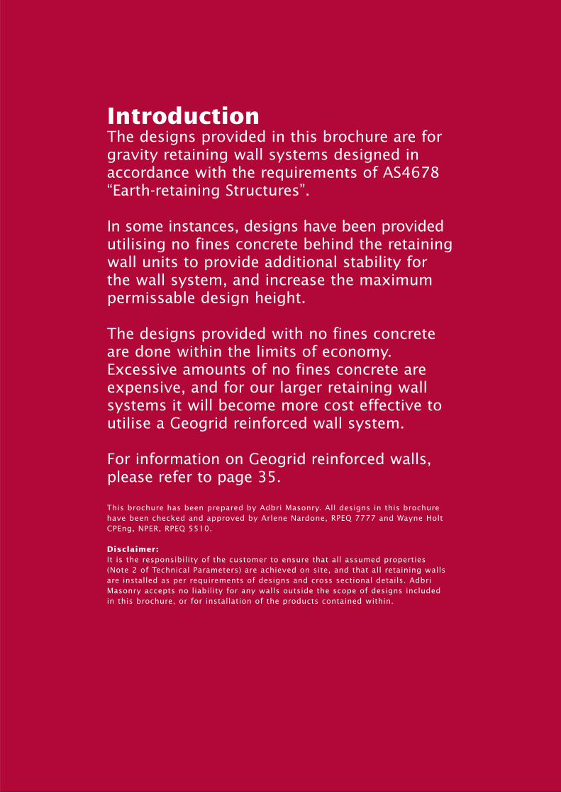
IntroductionThe designs provided in this brochure are forgravity retaining wall systems designed inaccordance with the requirements of AS4678“Earth-retaining Structures”.
In some instances, designs have been providedutilising no fines concrete behind the retainingwall units to provide additional stability forthe wall system, and increase the maximumpermissable design height.
The designs provided with no fines concreteare done within the limits of economy.Excessive amounts of no fines concrete areexpensive, and for our larger retaining wallsystems it will become more cost effective toutilise a Geogrid reinforced wall system.
For information on Geogrid reinforced walls,please refer to page 35.
This brochure has been prepared by Adbri Masonry. All designs in this brochurehave been checked and approved by Arlene Nardone, RPEQ 7777 and Wayne HoltCPEng, NPER, RPEQ 5510.
Disclaimer:It is the responsibility of the customer to ensure that all assumed properties (Note 2 of Technical Parameters) are achieved on site, and that all retaining wallsare installed as per requirements of designs and cross sectional details. AdbriMasonry accepts no liability for any walls outside the scope of designs included in this brochure, or for installation of the products contained within.

1.0 Technical Parameters03
1. Designed in accordance with the followingstandards unless noted otherwise.
AS4678:2002 – Earth retaining structuresAS1170.1:2002 – Loading CodeAS3700:2001 – Masonry CodeAS2870:1996 – Residential Slabs and
Footings
Concrete – Grade N20, min. 80mmslump, 20mm max.aggregate.
Aggregate – 12 - 20mm max.
No Fines Concrete – 20mm max. aggregate,6:1 Dry mix.
Notes: Where depth of aggregate exceeds 300mm, infill material is deemed to be the material being retained.If natural material on site does not meet or exceed a 30º internal friction angle, you must use a foundation replacement zone and a H/2aggregate infill material. NFC designs will not be applicable and further engineering advice will be required. A geotechical engineer willbe able to assist you in evaluating your in-situ material.
No design consideration has been given for rock excavation. With the assumed founding soil properties, the allowable bearing capacityunder a normal load has been taken at 100kPa.
The properties of the materials should be checked by a geotechnical engineer if doubt exists. Design has been based on assumed averageconditions for a gravity retaining wall and is considered applicable to soils where the site is classified as S, M, H or E with “ys” less than 70mm,where the wall is founded on natural undisturbed material. The infill of the wall must be compacted to ensure against rotation of the wall backwards.
3. These details are not applicable to the following designs and require the specific design input of a registered professional engineer:(a) Wall heights greater than shown in the tables(b) Surface slopes greater than 1V:4H at top of wall.(c) Site ground slopes greater than 1V:4H at toe of wall.(d) Retained material properties differing from those assumed in the design.(e) Walls founded on fill.(f) Rock encountered in excavation of area for infill material.(g) Site classified as “E” Ys greater than 70mm or “P”. For “E” sites where Ys exceeds 70mm a geotechnical engineer should be engaged.
For “P” sites, you must ensure that a safe bearing capacity of 100kPa is achieved, and satisfy yourself that no long term settlement will occur.(h) Site has major drainage or seepage problems.(i) Lack of global stability. Global stability should be checked by a qualified geotechnical engineer.(j) The founding material has a bearing capacity less than 100kPa.(k) Where the possibility of failure of the toe of the wall exists due to location of building or service pipe trenches in front of the
wall prior to or after construction of the retaining wall.(l) Where fences are detailed to be installed at the top of the wall which do not comply with the fence post installation detail
included in this brochure.(m) Where replacement material zones are not able to be installed as detailed in the design tables.
4. The conditions below must be met for residential walls denoted by * as shown in design tables for residential walls to 1200mm max. height:1. All retaining walls are designed to CMAA document MA53 (Segmental Concrete Gravity Retaining Walls Design and Construction Guide).2. All retaining walls shall comply with AS4678 Structure Classification A.3. These tables are only applicable to retaining walls that incorporate a low permeability surface membrane and drainage system
such that there can be no ingress of any water into the soil behind the retaining wall.4. Stuctures that do not incorporate a low permeability surface membrane and drainage system such that there can be no ingress
of any water into the soil behind the retaining wall are deemed to be outside the scope of this brochure.5. These tables are applicable to cuts in insitu soils. The tables are not applicable to cohesive fill.6. All retaining walls are designed for a maximum surcharge load of 2.5 kPa. If surcharge loads greater than 2.5 kPa are expected,
these designs will not be appropriate.7. The footing for Meadow Stone consists of at least 5% cement-stabilised crushed rock with dimensions as detailed. Before the bottom
course is positioned, the footing should be moistened to ensure bond between block and footing.
These walls have been designed in accordance with Rankine Bell Methodology.
5. The segmental retaining wall units in this brochure, with the exception of the Landmark system, have keys which are utilised for locating purposes only and are therefore not subject to the dimensional tolerances outlined in table 2.3 of AS4455.3:2008 “Segmental Retaining Wall Units”. The Landmark system has been independently tested to ensure integrity of the structural key for the purpose of constructing geogrid reinforced walls up to 20m in height.
2. The soil types and properties assumed in design are:
Insitu material 19
Gravel backfill 19
Concrete 24
Unit Weight kN/m3
30
37
N/A
Internal Friction Angle (ø)
0
0
0
CGM 18 37 0
Foundation replacement zones 19 42 0
No fines concrete (NFC) 19 N/A 0
Cohesive Strength kPaMaterial
2.0 General Notes04
1. Wall construction to be executed in accordance with the requirements of this brochure.
2. The walls have been designed for the following surcharge loads :• 1kPa (for garden walls) to 800mm maximum height.• 2.5kPa for walls between 800mm and 1500mm in height.• 5 kPa for walls exceeding 1500mm in height.• No Dead Loads have been allowed for.• Cohesion c=4kPa for residential walls denoted by * :Where there are any variations to the materials, soil conditions, loadings, drainage, geometry of the site or retaining wall, a registered engineer should be engaged to design the wall.
3. Where a fence is required at the top of the wall, the fence shall be installed in accordance with the detail in this manual.
4. Structures such as building footings, swimming pools, other retaining walls, storage facilities or solid panel fencing and loads such as from motor vehicle access must be kept clear such that the load is not placed within a line projected behind the wall from the founding level at 1V:1.5H. Where structures or driveways do intrude within this line a registered professional engineer should be engaged to design the wall.
5. Precautions must be taken where other building work or service trenches are excavated around the retaining wall, as it may be necessaryto use bridging foundations or other alternatives.
6. In all wall units with voids, stability depends on the blocks remaining filled, with Windsor, Diamond, Landmark, all the AB units and Hampton Stone Retaining Wall blocks, the first course should be installed with the shear key down and placed to give firm even bearings on the leveling pad, level front to back and side to side.
7. The base of the leveling pad excavation should be firm, dry and free of loose material. Any disturbed ground at the base of the trench should be compacted prior to footing construction. All retained material must be compacted by firm tamping using appropriatecompaction equipment. Materials in front of the wall should be founding soil or equivalent and thoroughly compacted immediately after the wall is out of the ground.
8. If the insitu material is equal to or exceeds the properties of the proposed infill material, then the insitu material shall be substituted for the infill material.
9. Precautions should be taken if cutting back the existing bank to ensure such excavation does not destabilize the footing of another structure.
10. Walls may be constructed to greater heights in specific applications with special engineering design.
11. Check with your local council whether building approval is required.
12. It is recommended that the top course is epoxied to the next course with waterproof construction epoxy as a precautionary measure.Adbri Masonry recommends the use of the AV Syntec product AV515 or equivalent.
13. Where these walls impose loads on other structures those other structures must be checked for strength and stability.
14. Where a foundation replacement zone is detailed, this will denote the removal of natural material where detailed, and replacement with CBR45 road base compacted to 98% Standard Relative Dry Density (RDD).
15. External interface friction angle is calculated as being equal to 2/3 ø where ø is the internal friction angle.
16. Subsoil drains should be flushed at regular intervals to ensure continuous proper functioning of the retaining wall drainage system.
17. Subsoil drains shall have outlet points at maximum 20m centres for dry application and maximum 5m centres for wet application.
3.0 Typical Details for Segmental Retaining Walls
05
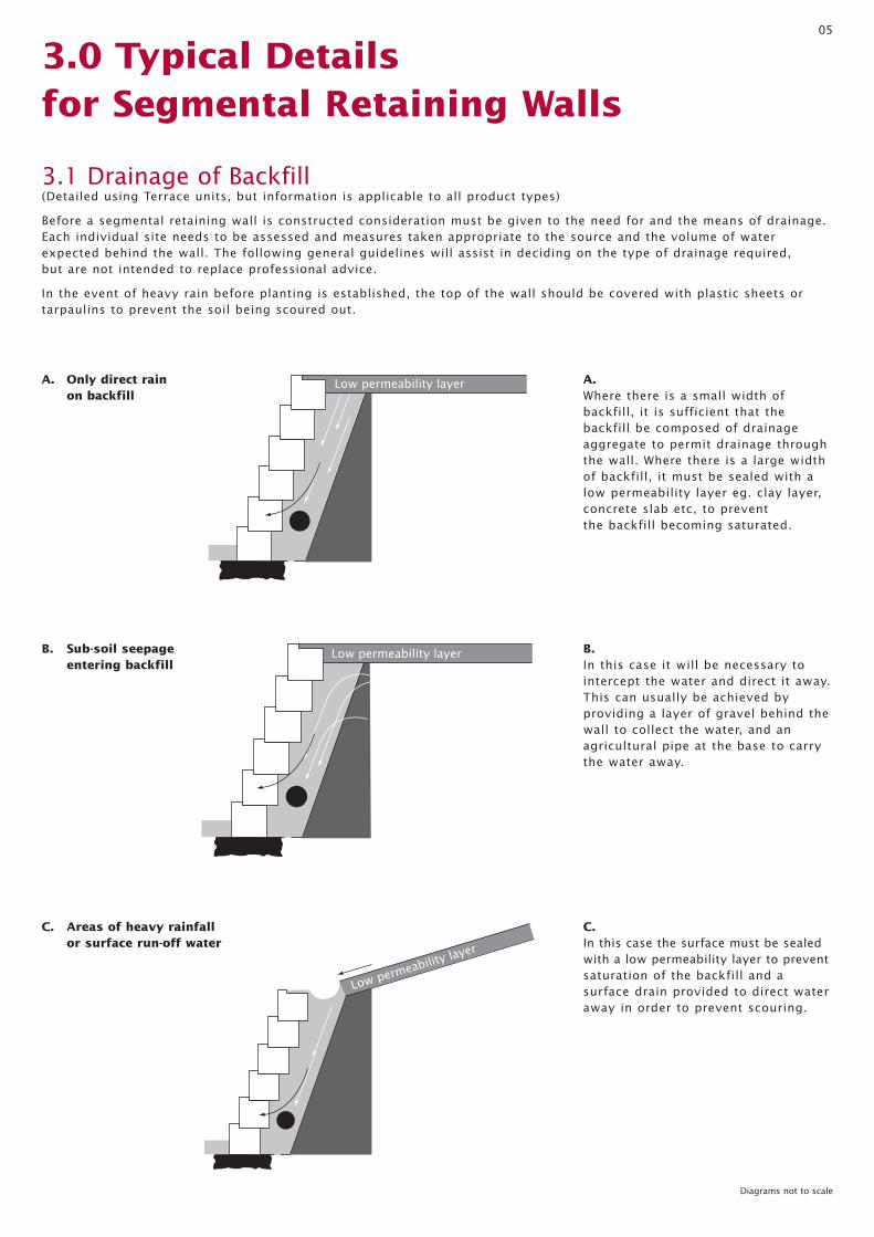
3.1 Drainage of Backfill (Detailed using Terrace units, but information is applicable to all product types)
Before a segmental retaining wall is constructed consideration must be given to the need for and the means of drainage.Each individual site needs to be assessed and measures taken appropriate to the source and the volume of waterexpected behind the wall. The following general guidelines will assist in deciding on the type of drainage required,but are not intended to replace professional advice.
In the event of heavy rain before planting is established, the top of the wall should be covered with plastic sheets or tarpaulins to prevent the soil being scoured out.
A. Where there is a small width of backfill, it is sufficient that the backfill be composed of drainageaggregate to permit drainage throughthe wall. Where there is a large widthof backfill, it must be sealed with alow permeability layer eg. clay layer,concrete slab etc, to prevent the backfill becoming saturated.
B. In this case it will be necessary tointercept the water and direct it away.This can usually be achieved by providing a layer of gravel behind thewall to collect the water, and an agricultural pipe at the base to carrythe water away.
C. In this case the surface must be sealedwith a low permeability layer to preventsaturation of the backfill and a surface drain provided to direct wateraway in order to prevent scouring.
Low permeability layer
Low permeability layer
Low permeability layer
A. Only direct rain on backfill
B. Sub-soil seepage entering backfill
C. Areas of heavy rainfall or surface run-off water
Diagrams not to scale
06
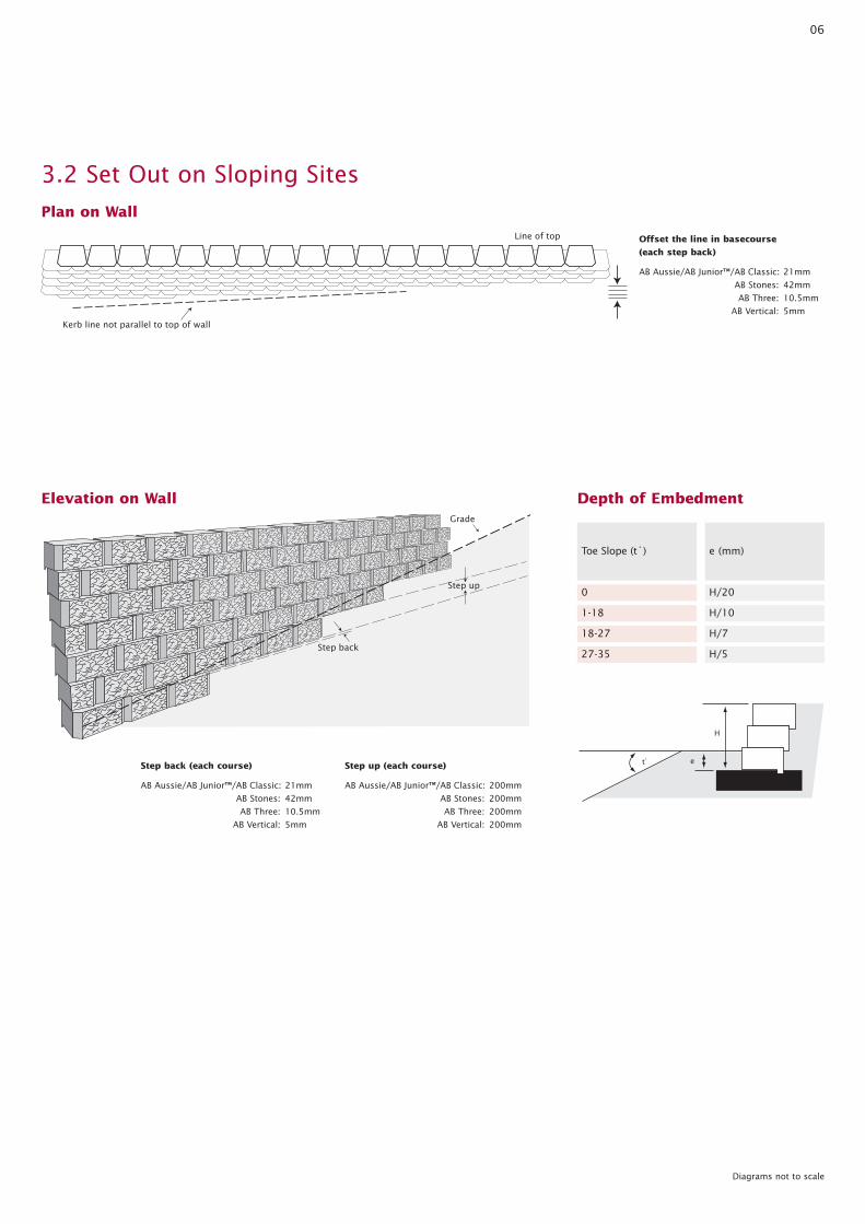
3.2 Set Out on Sloping Sites
0
1-18
18-27
Toe Slope (t˚)
H/20
H/10
H/7
27-35 H/5
e (mm)
Depth of Embedment
Plan on Wall
Line of top
Kerb line not parallel to top of wall
Elevation on WallGrade
Step up
Step back
H
et̊
Offset the line in basecourse
(each step back)
AB Aussie/AB Junior™/AB Classic: 21mm
AB Stones: 42mm
AB Three: 10.5mm
AB Vertical: 5mm
Diagrams not to scale
Step back (each course)
AB Aussie/AB Junior™/AB Classic: 21mm
AB Stones: 42mm
AB Three: 10.5mm
AB Vertical: 5mm
Step up (each course)
AB Aussie/AB Junior™/AB Classic: 200mm
AB Stones: 200mm
AB Three: 200mm
AB Vertical: 200mm

07
3.4 Typical No Fines Concrete Installation Details
Low permeability layer
Compacted roadbase
foundation replacement zone
Infill depth a)
t
b)
Diagrams not to scale
3.3 Typical Fence Post Detail
Grout fence posts into pvc pipes installed during wall construction
No structural loadswithin this line
1
1.5
Install pvc pipes of required diameter to underside of structural load line at required centres
No structural loadswithin this line
1
1.5
Detail A:*
------------
------------
Detail A:*
In Detail A:*Use galvanised steel plates and cast in place bolts to connect to 600 diameter piers at 3m ctrs reinforced with 4 12mm bars and 8mm ligatures at 400 ctrs.
c)
Place no fines concrete in single block lifts of 200mm or less (depending upon height of block). Ensure no fines is manipulated into V shaped void between units to ensure adequate bond between block and concrete mass.
If units are cored through, the no fines concrete must also completely fill the cored section of the block.
When using no fines concrete, ensure bondis achieved between wall units and nofines concrete. Ensure that no fines concreteis placed in voids between all units.
If any of the blocks have an internal core, this should be filled with no fines concrete as well.
Throat width (t) of no fines concrete shall never be less than 50mm. Blocks shall be modified by contractors where necessary to accommodate this.
Construction Details08
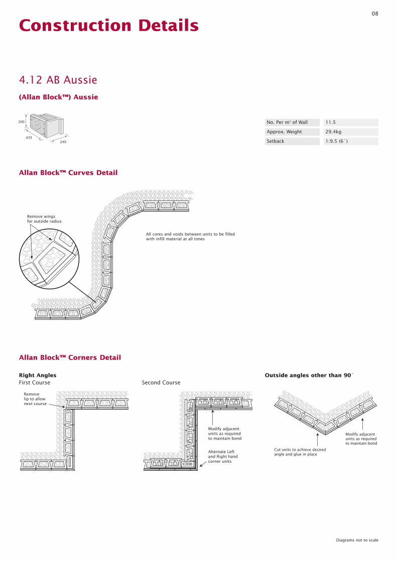
4.12 AB Aussie
(Allan Block™) Aussie
200
435240
No. Per m2 of Wall 11.5
Approx. Weight 29.4kg
Setback 1:9.5 (6˚)
Diagrams not to scale
Remove wings for outside radius
Allan Block™ Curves Detail
Allan Block™ Corners Detail
Remove lip to allow next course
Modify adjacent units as required to maintain bond
Alternate Left and Right hand corner units
Modify adjacent units as required to maintain bond
Cut units to achieve desired angle and glue in place
First Course Second CourseRight Angles Outside angles other than 90˚
All cores and voids between units to be filled with infill material at all times

09
1:4 max slope
1
1.5
1
9.5
100mm Subsoil drain socked fall to discharge maximum 20m centres
20mPa Concrete leveling pad
Additional extent of foundation replacement zone required when NFC infill material is used (refer to section 3.4)
Foundation replacement zone compacted roadbase 98% min RDD if required
Level Slope
Low permeability top soil layer
AB Aussie
AB Capper(Short)
"H" Design height
Infill Depth
e
Infill Material*
130
130
450
No structural loadswithin this line
*Refer to page 9 when using No Finesconcrete infill material
Diagrams not to scale
AB Aussie Typical Wall Section
"H" Design height
1:4 max slope
1
1.5
1
40
100mm Subsoil drain socked fall to discharge maximum 20m centres
20mPa Concrete leveling pad
Additional extent of foundation replacement zone required when NFC infill material is used (refer to section 3.4)
Foundation replacement zone compacted roadbase 98% min RDD if required
Level Slope
Low permeability top soil layer
AB Aussie Vertical
AB Capper(Short)
Infill Depth
e
Infill Material*
130
130
450
No structural loadswithin this line
*Refer to page 9 when using No Finesconcrete infill material
AB Aussie Vertical Typical Wall Section

10
2600 Level
2400 Level
2200 Level
Surface Slope
2000 Level
Design Height ‘H’(mm)
5 Replacement Zone
5 Replacement Zone
5 Replacement Zone
Foundation Material
5 Replacement Zone
Surcharge Load(kPa)
NFC 800
NFC 750
NFC 700
Infill Material Depth(mm)
NFC 600
1800 Level
1600 Level
1400 Level
1200 Level
5 Replacement Zone
5 Replacement Zone
2.5 Replacement Zone
2.5 Replacement Zone
NFC 550
NFC 500
NFC 350
NFC 300
1000 Level
800 Level
600 Level
400 Level
2.5 Replacement Zone
1 Replacement Zone
1 Natural Material
1 Natural Material
NFC 300
Aggregate 300
Aggregate 300
Aggregate 300
2400 1:4 maximum
2200 1:4 maximum
2000 1:4 maximum
5 Replacement Zone
5 Replacement Zone
5 Replacement Zone
NFC 1000
NFC 900
NFC 850
Infill Material
AB Aussie Retaining Wall Design HeightsResidential Retaining Walls(Including residential subdivisions)
NFC denotes the use of No Fines Concrete. Where NFC is to be used, you must ensure that the natural site material has an internal friction angle of 30˚ or more. These designs are not suitable for clay sites.
1800 1:4 maximum 5 Replacement Zone NFC 750
1600 1:4 maximum 5 Replacement Zone NFC 650
1400 1:4 maximum 2.5 Replacement Zone NFC 450
1200 1:4 maximum 2.5 Replacement Zone NFC 350
1000 1:4 maximum 2.5 Replacement Zone NFC 300
800 1:4 maximum 1 Replacement Zone Aggregate 400
600 1:4 maximum 1 Natural Material Aggregate 300
400 1:4 maximum 1 Natural Material Aggregate 300

11
2600 Level
2400 Level
2200 Level
Surface Slope
2000 Level
Design Height ‘H’(mm)
5 Replacement Zone
5 Replacement Zone
5 Replacement Zone
Foundation Material
5 Replacement Zone
Surcharge Load(kPa)
NFC 800
NFC 750
NFC 700
Infill Material Depth(mm)
NFC 600
1800 Level
1600 Level
1400 Level
1200 Level
5 Replacement Zone
5 Replacement Zone
2.5 Replacement Zone
2.5 Replacement Zone
NFC 550
NFC 500
NFC 350
NFC 300
1000 Level
800 Level
600 Level
400 Level
2.5 Replacement Zone
1 Replacement Zone
1 Natural Material
1 Natural Material
NFC 300
Aggregate 300
Aggregate 300
Aggregate 300
2400 1:4 maximum 5 Replacement Zone NFC 1000
2200 1:4 maximum 5 Replacement Zone NFC 900
2000 1:4 maximum 5 Replacement Zone NFC 850
1800 1:4 maximum 5 Replacement Zone NFC 750
1600 1:4 maximum 5 Replacement Zone NFC 650
1400 1:4 maximum 2.5 Replacement Zone NFC 450
1200 1:4 maximum 2.5 Replacement Zone NFC 350
1000 1:4 maximum 2.5 Replacement Zone NFC 300
800 1:4 maximum 1 Replacement Zone Aggregate 400
600 1:4 maximum 1 Natural Material Aggregate 300
400 1:4 maximum 1 Natural Material Aggregate 300
Infill Material
NFC denotes the use of No Fines Concrete. Where NFC is to be used, you must ensure that the natural site material has an internal friction angle of 30˚ or more. These designs are not suitable for clay sites.
AB Aussie Retaining Wall Design HeightsCommercial Retaining Walls

12
2600 Level
2400 Level
2200 Level
Surface Slope
2000 Level
Design Height ‘H’(mm)
5 Replacement Zone
5 Replacement Zone
5 Replacement Zone
Foundation Material
5 Replacement Zone
Surcharge Load(kPa)
NFC 950
NFC 900
NFC 800
Infill Material Depth(mm)
NFC 750
1800 Level
1600 Level
1400 Level
1200 Level
5 Replacement Zone
5 Replacement Zone
2.5 Replacement Zone
2.5 Replacement Zone
NFC 650
NFC 550
NFC 400
NFC 300
1000 Level
800 Level
600 Level
400 Level
2.5 Replacement Zone
1 Replacement Zone
1 Natural Material
1 Natural Material
NFC 300
Aggregate 400
Aggregate 300
Aggregate 300
2400 1:4 maximum
2200 1:4 maximum
2000 1:4 maximum
5 Replacement Zone
5 Replacement Zone
5 Replacement Zone
NFC 1100
NFC 1000
NFC 950
Infill Material
AB Aussie Vertical Retaining Wall Design HeightsResidential Retaining Walls(Including residential subdivisions)
NFC denotes the use of No Fines Concrete. Where NFC is to be used, you must ensure that the natural site material has an internal friction angle of 30˚ or more. These designs are not suitable for clay sites.
1800 1:4 maximum 5 Replacement Zone NFC 850
1600 1:4 maximum 5 Replacement Zone NFC 750
1400 1:4 maximum 2.5 Replacement Zone NFC 550
1200 1:4 maximum 2.5 Replacement Zone NFC 450
1000 1:4 maximum 2.5 Replacement Zone NFC 350
800 1:4 maximum 1 Replacement Zone Aggregate 400
600 1:4 maximum 1 Replacement Zone Aggregate 300
400 1:4 maximum 1 Replacement Zone Aggregate 300

13
2600 Level
2400 Level
2200 Level
Surface Slope
2000 Level
Design Height ‘H’(mm)
5 Replacement Zone
5 Replacement Zone
5 Replacement Zone
Foundation Material
5 Replacement Zone
Surcharge Load(kPa)
NFC 950
NFC 900
NFC 800
Infill Material Depth(mm)
NFC 750
1800 Level
1600 Level
1400 Level
1200 Level
5 Replacement Zone
5 Replacement Zone
2.5 Replacement Zone
2.5 Replacement Zone
NFC 650
NFC 550
NFC 400
NFC 300
1000 Level
800 Level
600 Level
400 Level
2.5 Replacement Zone
1 Replacement Zone
1 Natural Material
1 Natural Material
NFC 300
Aggregate 400
Aggregate 300
Aggregate 300
2400 1:4 maximum 5 Replacement Zone NFC 1100
2200 1:4 maximum 5 Replacement Zone NFC 1000
2000 1:4 maximum 5 Replacement Zone NFC 950
1800 1:4 maximum 5 Replacement Zone NFC 850
1600 1:4 maximum 5 Replacement Zone NFC 750
1400 1:4 maximum 2.5 Replacement Zone NFC 550
1200 1:4 maximum 2.5 Replacement Zone NFC 450
1000 1:4 maximum 2.5 Replacement Zone NFC 350
800 1:4 maximum 1 Replacement Zone Aggregate 400
600 1:4 maximum 1 Replacement Zone Aggregate 300
400 1:4 maximum 1 Replacement Zone Aggregate 300
Infill Material
NFC denotes the use of No Fines Concrete. Where NFC is to be used, you must ensure that the natural site material has an internal friction angle of 30˚ or more. These designs are not suitable for clay sites.
AB Aussie Vertical Retaining Wall Design HeightsCommercial Retaining Walls

14
4.13 AB Classic
Diagrams not to scale
(Allan Block™) Classic
200
435305
No. Per m2 of Wall 11.5
Approx. Weight 31.25kg
Setback 1:9.5 (6˚)
Remove wings for outside radius
Allan Block™ Curves Detail
Allan Block™ Corners Detail
Remove lip to allow next course
Modify adjacent units as required to maintain bond
Alternate Left and Right hand corner units
Modify adjacent units as required to maintain bond
Cut units to achieve desired angle and glue in place
First Course Second CourseRight Angles Outside angles other than 90˚
All cores and voids between units to be filled with infill material at all times

15
1:4 max slope
1
1.5
1
9.5
20mPa Concrete leveling pad
Level Slope
Low permeability top soil layer
AB Classic
AB Capper
150
150
"H" Design height
Infill Depth
e
600
Infill Material*
100mm Subsoil drain socked fall to discharge maximum 20m centres
Additional extent of foundation replacement zone required when NFC infill material is used (refer to section 3.4)
Foundation replacement zone compacted roadbase 98% min RDD if required
No structural loadswithin this line
*Refer to page 9 when using No Finesconcrete infill material
Diagrams not to scale
AB Classic Typical Wall Section
16
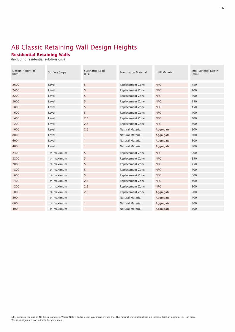
2600 Level
2400 Level
2200 Level
Surface Slope
2000 Level
Design Height ‘H’(mm)
5 Replacement Zone
5 Replacement Zone
5 Replacement Zone
Foundation Material
5 Replacement Zone
Surcharge Load(kPa)
NFC 750
NFC 700
NFC 600
Infill Material Depth(mm)
NFC 550
1800 Level
1600 Level
1400 Level
1200 Level
5 Replacement Zone
5 Replacement Zone
2.5 Replacement Zone
2.5 Replacement Zone
NFC 450
NFC 400
NFC 300
NFC 300
1000 Level
800 Level
600 Level
400 Level
2.5 Natural Material
1 Natural Material
1 Natural Material
1 Natural Material
Aggregate 300
Aggregate 300
Aggregate 300
Aggregate 300
2400 1:4 maximum
2200 1:4 maximum
2000 1:4 maximum
5 Replacement Zone
5 Replacement Zone
5 Replacement Zone
NFC 900
NFC 850
NFC 750
Infill Material
AB Classic Retaining Wall Design HeightsResidential Retaining Walls(Including residential subdivisions)
NFC denotes the use of No Fines Concrete. Where NFC is to be used, you must ensure that the natural site material has an internal friction angle of 30˚ or more. These designs are not suitable for clay sites.
1800 1:4 maximum 5 Replacement Zone NFC 700
1600 1:4 maximum 5 Replacement Zone NFC 600
1400 1:4 maximum 2.5 Replacement Zone NFC 400
1200 1:4 maximum 2.5 Replacement Zone NFC 300
1000 1:4 maximum 2.5 Replacement Zone Aggregate 500
800 1:4 maximum 1 Natural Material Aggregate 400
600 1:4 maximum 1 Natural Material Aggregate 300
400 1:4 maximum 1 Natural Material Aggregate 300

17
2600 Level
2400 Level
2200 Level
Surface Slope
2000 Level
Design Height ‘H’(mm)
5 Replacement Zone
5 Replacement Zone
5 Replacement Zone
Foundation Material
5 Replacement Zone
Surcharge Load(kPa)
NFC 750
NFC 700
NFC 600
Infill Material Depth(mm)
NFC 550
1800 Level
1600 Level
1400 Level
1200 Level
5 Replacement Zone
5 Replacement Zone
2.5 Replacement Zone
2.5 Replacement Zone
NFC 450
NFC 400
NFC 300
NFC 300
1000 Level
800 Level
600 Level
400 Level
2.5 Replacement Zone
1 Natural Material
1 Natural Material
1 Natural Material
Aggregate 300
Aggregate 300
Aggregate 300
Aggregate 300
2400 1:4 maximum 5 Replacement Zone NFC 900
2200 1:4 maximum 5 Replacement Zone NFC 850
2000 1:4 maximum 5 Replacement Zone NFC 750
1800 1:4 maximum 5 Replacement Zone NFC 700
1600 1:4 maximum 5 Replacement Zone NFC 600
1400 1:4 maximum 2.5 Replacement Zone NFC 400
1200 1:4 maximum 2.5 Replacement Zone NFC 300
1000 1:4 maximum 2.5 Replacement Zone Aggregate 500
800 1:4 maximum 1 Natural Material Aggregate 400
600 1:4 maximum 1 Natural Material Aggregate 300
400 1:4 maximum 1 Natural Material Aggregate 300
Infill Material
NFC denotes the use of No Fines Concrete. Where NFC is to be used, you must ensure that the natural site material has an internal friction angle of 30˚ or more. These designs are not suitable for clay sites.
AB Classic Retaining Wall Design HeightsCommercial Retaining Walls

18
4.14 AB Junior™
Diagrams not to scale
(Allan Block™) Junior
200
216 240
No. Per m2 of Wall 23
Approx. Weight 14.7kg
Setback 1:9.5 (6˚)
Remove wings for outside radius
Allan Block™ Curves Detail
Allan Block™ Corners Detail
Remove lip to allow next course
Modify adjacent units as required to maintain bond
Alternate Left and Right hand corner units
Modify adjacent units as required to maintain bond
Cut units to achieve desired angle and glue in place
First Course Second CourseRight Angles Outside angles other than 90˚
All cores and voids between units to be filled with infill material at all times

19
1:4 max slope
1
1.5
1
9.5
Level Slope
Low permeability top soil layer
AB Junior
AB Capper
(Short)
Infill Depth
e
Infill Material*
130
130
450
20mPa Concrete leveling pad
100mm Subsoil drain socked fall to discharge maximum 20m centres
Additional extent of foundation replacement zone required when NFC infill material is used (refer to section 3.4)
Foundation replacement zone compacted roadbase 98% min RDD if required
No structural loadswithin this line
"H" Design height
*Refer to page 9 when using No Finesconcrete infill material
Diagrams not to scale
AB Junior™ Typical Wall Section
20
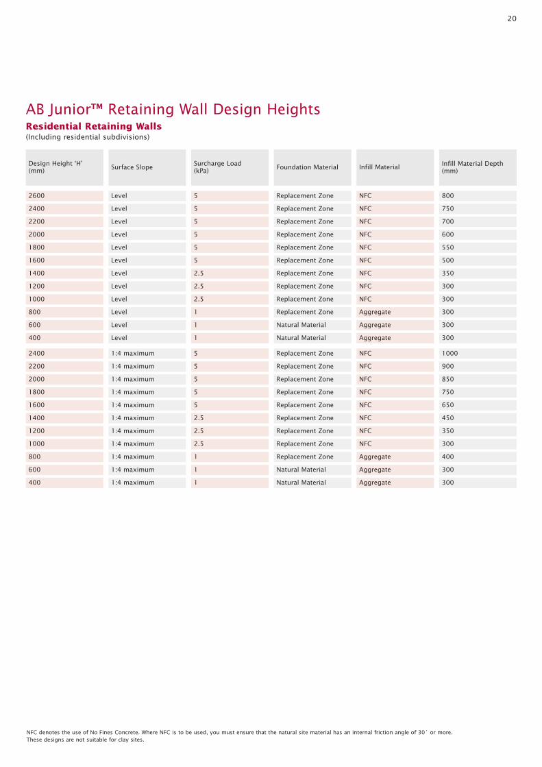
2600 Level
2400 Level
2200 Level
Surface Slope
2000 Level
Design Height ‘H’(mm)
5 Replacement Zone
5 Replacement Zone
5 Replacement Zone
Foundation Material
5 Replacement Zone
Surcharge Load(kPa)
NFC 800
NFC 750
NFC 700
Infill Material Depth(mm)
NFC 600
1800 Level
1600 Level
1400 Level
1200 Level
5 Replacement Zone
5 Replacement Zone
2.5 Replacement Zone
2.5 Replacement Zone
NFC 550
NFC 500
NFC 350
NFC 300
1000 Level
800 Level
600 Level
400 Level
2.5 Replacement Zone
1 Replacement Zone
1 Natural Material
1 Natural Material
NFC 300
Aggregate 300
Aggregate 300
Aggregate 300
2400 1:4 maximum
2200 1:4 maximum
2000 1:4 maximum
5 Replacement Zone
5 Replacement Zone
5 Replacement Zone
NFC 1000
NFC 900
NFC 850
Infill Material
AB Junior™ Retaining Wall Design HeightsResidential Retaining Walls(Including residential subdivisions)
NFC denotes the use of No Fines Concrete. Where NFC is to be used, you must ensure that the natural site material has an internal friction angle of 30˚ or more. These designs are not suitable for clay sites.
1800 1:4 maximum 5 Replacement Zone NFC 750
1600 1:4 maximum 5 Replacement Zone NFC 650
1400 1:4 maximum 2.5 Replacement Zone NFC 450
1200 1:4 maximum 2.5 Replacement Zone NFC 350
1000 1:4 maximum 2.5 Replacement Zone NFC 300
800 1:4 maximum 1 Replacement Zone Aggregate 400
600 1:4 maximum 1 Natural Material Aggregate 300
400 1:4 maximum 1 Natural Material Aggregate 300
21
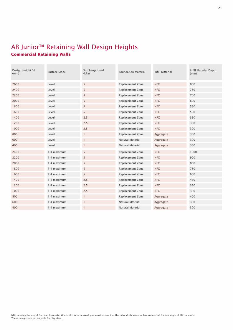
2600 Level
2400 Level
2200 Level
Surface Slope
2000 Level
Design Height ‘H’(mm)
5 Replacement Zone
5 Replacement Zone
5 Replacement Zone
Foundation Material
5 Replacement Zone
Surcharge Load(kPa)
NFC 800
NFC 750
NFC 700
Infill Material Depth(mm)
NFC 600
1800 Level
1600 Level
1400 Level
1200 Level
5 Replacement Zone
5 Replacement Zone
2.5 Replacement Zone
2.5 Replacement Zone
NFC 550
NFC 500
NFC 350
NFC 300
1000 Level
800 Level
600 Level
400 Level
2.5 Replacement Zone
1 Replacement Zone
1 Natural Material
1 Natural Material
NFC 300
Aggregate 300
Aggregate 300
Aggregate 300
2400 1:4 maximum 5 Replacement Zone NFC 1000
2200 1:4 maximum 5 Replacement Zone NFC 900
2000 1:4 maximum 5 Replacement Zone NFC 850
1800 1:4 maximum 5 Replacement Zone NFC 750
1600 1:4 maximum 5 Replacement Zone NFC 650
1400 1:4 maximum 2.5 Replacement Zone NFC 450
1200 1:4 maximum 2.5 Replacement Zone NFC 350
1000 1:4 maximum 2.5 Replacement Zone NFC 300
800 1:4 maximum 1 Replacement Zone Aggregate 400
600 1:4 maximum 1 Natural Material Aggregate 300
400 1:4 maximum 1 Natural Material Aggregate 300
Infill Material
NFC denotes the use of No Fines Concrete. Where NFC is to be used, you must ensure that the natural site material has an internal friction angle of 30˚ or more. These designs are not suitable for clay sites.
AB Junior™ Retaining Wall Design HeightsCommercial Retaining Walls

22
4.15 AB Stones
Diagrams not to scale
(Allan Block™) Stones
200
435
305
No. Per m2 of Wall 11.5
Approx. Weight 31.25kg
Setback 1:4.75 (12˚)
Remove wings for outside radius
Allan Block™ Curves Detail
Allan Block™ Corners Detail
Remove lip to allow next course
Modify adjacent units as required to maintain bond
Alternate Left and Right hand corner units
Modify adjacent units as required to maintain bond
Cut units to achieve desired angle and glue in place
First Course Second CourseRight Angles Outside angles other than 90˚
All cores and voids between units to be filled with infill material at all times
23
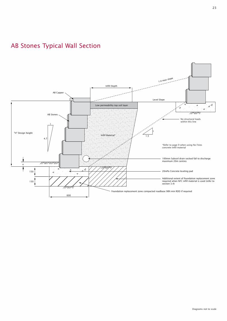
1:4 max slope
1
1.5
1
4.7
Level Slope
Low permeability top soil layer
AB Stones
AB Capper
150
150
"H" Design height
Infill Depth
e
600
Infill Material*
100mm Subsoil drain socked fall to discharge maximum 20m centres
20mPa Concrete leveling pad
Additional extent of foundation replacement zone required when NFC infill material is used (refer to section 3.4)
Foundation replacement zone compacted roadbase 98% min RDD if required
No structural loadswithin this line
*Refer to page 9 when using No Finesconcrete infill material
Diagrams not to scale
AB Stones Typical Wall Section

24
2600 Level
2400 Level
2200 Level
Surface Slope
2000 Level
Design Height ‘H’(mm)
5 Replacement Zone
5 Replacement Zone
5 Replacement Zone
Foundation Material
5 Replacement Zone
Surcharge Load(kPa)
NFC 600
NFC 550
NFC 500
Infill Material Depth(mm)
NFC 450
1800 Level
1600 Level
1400 Level
1200 Level
5 Replacement Zone
5 Replacement Zone
2.5 Replacement Zone
2.5 Natural Material
NFC 400
NFC 300
Aggregate 700
Aggregate 300
1000 Level
800 Level
600 Level
400 Level
2.5 Natural Material
1 Natural Material
1 Natural Material
1 Natural Material
Aggregate 300
Aggregate 300
Aggregate 300
Aggregate 300
2400 1:4 maximum
2200 1:4 maximum
2000 1:4 maximum
5 Replacement Zone
5 Replacement Zone
5 Replacement Zone
NFC 750
NFC 675
NFC 625
Infill Material
AB Stones Retaining Wall Design HeightsResidential Retaining Walls(Including residential subdivisions)
NFC denotes the use of No Fines Concrete. Where NFC is to be used, you must ensure that the natural site material has an internal friction angle of 30˚ or more. These designs are not suitable for clay sites.
1800 1:4 maximum 5 Replacement Zone NFC 550
1600 1:4 maximum 5 Replacement Zone NFC 475
1400 1:4 maximum 2.5 Replacement Zone Aggregate 700
1200 1:4 maximum 2.5 Replacement Zone Aggregate 600
1000 1:4 maximum 2.5 Replacement Zone Aggregate 500
800 1:4 maximum 1 Natural Material Aggregate 400
600 1:4 maximum 1 Natural Material Aggregate 300
400 1:4 maximum 1 Natural Material Aggregate 300

25
2600 Level
2400 Level
2200 Level
Surface Slope
2000 Level
Design Height ‘H’(mm)
5 Replacement Zone
5 Replacement Zone
5 Replacement Zone
Foundation Material
5 Replacement Zone
Surcharge Load(kPa)
NFC 600
NFC 550
NFC 500
Infill Material Depth(mm)
NFC 450
1800 Level
1600 Level
1400 Level
1200 Level
5 Replacement Zone
5 Replacement Zone
2.5 Replacement Zone
2.5 Replacement Zone
NFC 400
NFC 300
Aggregate 700
Aggregate 600
1000 Level
800 Level
600 Level
400 Level
2.5 Replacement Zone
1 Natural Material
1 Natural Material
1 Natural Material
Aggregate 500
Aggregate 400
Aggregate 300
Aggregate 300
2400 1:4 maximum 5 Replacement Zone NFC 750
2200 1:4 maximum 5 Replacement Zone NFC 700
2000 1:4 maximum 5 Replacement Zone NFC 650
1800 1:4 maximum 5 Replacement Zone NFC 550
1600 1:4 maximum 5 Replacement Zone NFC 500
1400 1:4 maximum 2.5 Replacement Zone Aggregate 700
1200 1:4 maximum 2.5 Replacement Zone Aggregate 600
1000 1:4 maximum 2.5 Replacement Zone Aggregate 500
800 1:4 maximum 1 Natural Material Aggregate 400
600 1:4 maximum 1 Natural Material Aggregate 300
400 1:4 maximum 1 Natural Material Aggregate 300
Infill Material
NFC denotes the use of No Fines Concrete. Where NFC is to be used, you must ensure that the natural site material has an internal friction angle of 30˚ or more. These designs are not suitable for clay sites.
AB Stones Retaining Wall Design HeightsCommercial Retaining Walls

26
4.16 AB Three
Diagrams not to scale
(Allan Block™) Three
200
435305
No. Per m2 of Wall 11.5
Approx. Weight 31.25kg
Setback 1:19 (3˚)
Remove wings for outside radius
Allan Block™ Curves Detail
Allan Block™ Corners Detail
Remove lip to allow next course
Modify adjacent units as required to maintain bond
Alternate Left and Right hand corner units
Modify adjacent units as required to maintain bond
Cut units to achieve desired angle and glue in place
First Course Second CourseRight Angles Outside angles other than 90˚
All cores and voids between units to be filled with infill material at all times

27
1:4 max slope
1
1.5
1
19
Level Slope
AB Three
AB Capper
150
150
"H" Design height
Infill Depth
e
Infill Material*
Low permeability top soil layer
600
100mm Subsoil drain socked fall to discharge maximum 20m centres
20mPa Concrete leveling pad
Additional extent of foundation replacement zone required when NFC infill material is used (refer to section 3.4)
Foundation replacement zone compacted roadbase 98% min RDD if required
No structural loadswithin this line
*Refer to page 9 when using No Finesconcrete infill material
Diagrams not to scale
AB Three Typical Wall Section
28
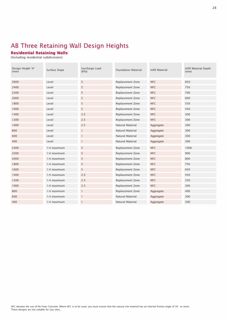
2600 Level
2400 Level
2200 Level
Surface Slope
2000 Level
Design Height ‘H’(mm)
5 Replacement Zone
5 Replacement Zone
5 Replacement Zone
Foundation Material
5 Replacement Zone
Surcharge Load(kPa)
NFC 850
NFC 750
NFC 700
Infill Material Depth(mm)
NFC 600
1800 Level
1600 Level
1400 Level
1200 Level
5 Replacement Zone
5 Replacement Zone
2.5 Replacement Zone
2.5 Replacement Zone
NFC 550
NFC 450
NFC 300
NFC 300
1000 Level
800 Level
600 Level
400 Level
2.5 Natural Material
1 Natural Material
1 Natural Material
1 Natural Material
Aggregate 300
Aggregate 300
Aggregate 300
Aggregate 300
2400 1:4 maximum
2200 1:4 maximum
2000 1:4 maximum
5 Replacement Zone
5 Replacement Zone
5 Replacement Zone
NFC 1000
NFC 900
NFC 800
Infill Material
AB Three Retaining Wall Design HeightsResidential Retaining Walls(Including residential subdivisions)
NFC denotes the use of No Fines Concrete. Where NFC is to be used, you must ensure that the natural site material has an internal friction angle of 30˚ or more. These designs are not suitable for clay sites.
1800 1:4 maximum 5 Replacement Zone NFC 750
1600 1:4 maximum 5 Replacement Zone NFC 650
1400 1:4 maximum 2.5 Replacement Zone NFC 450
1200 1:4 maximum 2.5 Replacement Zone NFC 350
1000 1:4 maximum 2.5 Replacement Zone NFC 300
800 1:4 maximum 1 Replacement Zone Aggregate 400
600 1:4 maximum 1 Natural Material Aggregate 300
400 1:4 maximum 1 Natural Material Aggregate 300

29
2600 Level
2400 Level
2200 Level
Surface Slope
2000 Level
Design Height ‘H’(mm)
5 Replacement Zone
5 Replacement Zone
5 Replacement Zone
Foundation Material
5 Replacement Zone
Surcharge Load(kPa)
NFC 850
NFC 750
NFC 700
Infill Material Depth(mm)
NFC 600
1800 Level
1600 Level
1400 Level
1200 Level
5 Replacement Zone
5 Replacement Zone
2.5 Replacement Zone
2.5 Replacement Zone
NFC 550
NFC 450
NFC 300
NFC 300
1000 Level
800 Level
600 Level
400 Level
2.5 Natural Material
1 Natural Material
1 Natural Material
1 Natural Material
Aggregate 300
Aggregate 300
Aggregate 300
Aggregate 300
2400 1:4 maximum 5 Replacement Zone NFC 1000
2200 1:4 maximum 5 Replacement Zone NFC 900
2000 1:4 maximum 5 Replacement Zone NFC 800
1800 1:4 maximum 5 Replacement Zone NFC 750
1600 1:4 maximum 5 Replacement Zone NFC 650
1400 1:4 maximum 2.5 Replacement Zone NFC 450
1200 1:4 maximum 2.5 Replacement Zone NFC 350
1000 1:4 maximum 2.5 Replacement Zone NFC 300
800 1:4 maximum 1 Replacement Zone Aggregate 400
600 1:4 maximum 1 Natural Material Aggregate 300
400 1:4 maximum 1 Natural Material Aggregate 300
Infill Material
NFC denotes the use of No Fines Concrete. Where NFC is to be used, you must ensure that the natural site material has an internal friction angle of 30˚ or more. These designs are not suitable for clay sites.
AB Three Retaining Wall Design HeightsCommercial Retaining Walls

30
4.17 AB Vertical
Diagrams not to scale
(Allan Block™) Vertical
200
435305
No. Per m2 of Wall 11.5
Approx. Weight 31.25kg
Setback 1:40 (14˚)
Remove wings for outside radius
Allan Block™ Curves Detail
Allan Block™ Corners Detail
Remove lip to allow next course
Modify adjacent units as required to maintain bond
Alternate Left and Right hand corner units
Modify adjacent units as required to maintain bond
Cut units to achieve desired angle and glue in place
First Course Second CourseRight Angles Outside angles other than 90˚
All cores and voids between units to be filled with infill material at all times
31
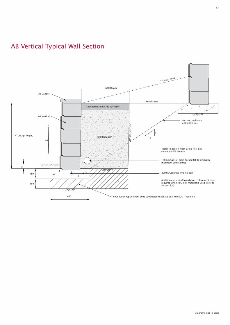
1:4 max slope
1
1.5
1
40
Level Slope
Low permeability top soil layer
AB Vertical
AB Capper
150
150
"H" Design heightInfill Material*
Infill Depth
e
600
100mm Subsoil drain socked fall to discharge maximum 20m centres
20mPa Concrete leveling pad
Additional extent of foundation replacement zone required when NFC infill material is used (refer to section 3.4)
Foundation replacement zone compacted roadbase 98% min RDD if required
No structural loadswithin this line
*Refer to page 9 when using No Finesconcrete infill material
Diagrams not to scale
AB Vertical Typical Wall Section
32
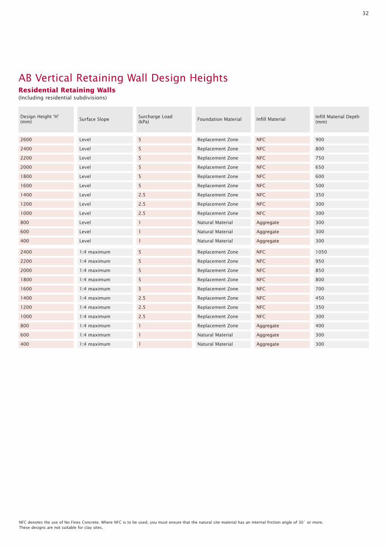
2600 Level
2400 Level
2200 Level
Surface Slope
2000 Level
Design Height ‘H’(mm)
5 Replacement Zone
5 Replacement Zone
5 Replacement Zone
Foundation Material
5 Replacement Zone
Surcharge Load(kPa)
NFC 900
NFC 800
NFC 750
Infill Material Depth(mm)
NFC 650
1800 Level
1600 Level
1400 Level
1200 Level
5 Replacement Zone
5 Replacement Zone
2.5 Replacement Zone
2.5 Replacement Zone
NFC 600
NFC 500
NFC 350
NFC 300
1000 Level
800 Level
600 Level
400 Level
2.5 Replacement Zone
1 Natural Material
1 Natural Material
1 Natural Material
NFC 300
Aggregate 300
Aggregate 300
Aggregate 300
2400 1:4 maximum
2200 1:4 maximum
2000 1:4 maximum
5 Replacement Zone
5 Replacement Zone
5 Replacement Zone
NFC 1050
NFC 950
NFC 850
Infill Material
AB Vertical Retaining Wall Design HeightsResidential Retaining Walls(Including residential subdivisions)
NFC denotes the use of No Fines Concrete. Where NFC is to be used, you must ensure that the natural site material has an internal friction angle of 30˚ or more. These designs are not suitable for clay sites.
1800 1:4 maximum 5 Replacement Zone NFC 800
1600 1:4 maximum 5 Replacement Zone NFC 700
1400 1:4 maximum 2.5 Replacement Zone NFC 450
1200 1:4 maximum 2.5 Replacement Zone NFC 350
1000 1:4 maximum 2.5 Replacement Zone NFC 300
800 1:4 maximum 1 Replacement Zone Aggregate 400
600 1:4 maximum 1 Natural Material Aggregate 300
400 1:4 maximum 1 Natural Material Aggregate 300

33
2600 Level
2400 Level
2200 Level
Surface Slope
2000 Level
Design Height ‘H’(mm)
5 Replacement Zone
5 Replacement Zone
5 Replacement Zone
Foundation Material
5 Replacement Zone
Surcharge Load(kPa)
NFC 900
NFC 800
NFC 750
Infill Material Depth(mm)
NFC 650
1800 Level
1600 Level
1400 Level
1200 Level
5 Replacement Zone
5 Replacement Zone
2.5 Replacement Zone
2.5 Replacement Zone
NFC 600
NFC 500
NFC 350
NFC 300
1000 Level
800 Level
600 Level
400 Level
2.5 Replacement Zone
1 Natural Material
1 Natural Material
1 Natural Material
NFC 300
Aggregate 300
Aggregate 300
Aggregate 300
2400 1:4 maximum 5 Replacement Zone NFC 1050
2200 1:4 maximum 5 Replacement Zone NFC 950
2000 1:4 maximum 5 Replacement Zone NFC 850
1800 1:4 maximum 5 Replacement Zone NFC 800
1600 1:4 maximum 5 Replacement Zone NFC 700
1400 1:4 maximum 2.5 Replacement Zone NFC 450
1200 1:4 maximum 2.5 Replacement Zone NFC 350
1000 1:4 maximum 2.5 Replacement Zone NFC 300
800 1:4 maximum 1 Replacement Zone Aggregate 400
600 1:4 maximum 1 Natural Material Aggregate 300
400 1:4 maximum 1 Natural Material Aggregate 300
Infill Material
NFC denotes the use of No Fines Concrete. Where NFC is to be used, you must ensure that the natural site material has an internal friction angle of 30˚ or more. These designs are not suitable for clay sites.
AB Vertical Retaining Wall Design HeightsCommercial Retaining Walls

34
R G 2R + G
5.0 Typical Details for Creating Steps and Stairs
Diagrams not to scale
Maximum Minimum
190 115
Maximum Minimum
355 240
Maximum Minimum
700 550
Permissable Step Dimensions(in accordance with BCA requirements)
Install a paver with bullnoseedge to create stair tread
Use mass concrete or compacted earth at rear of wall units to providesolid foundation for subsequent stair treads
Install mass concrete levelling pad to underside of first step
Install two retaining wall units back to back to create step
Use mass concrete or compacted earth at rear of wall units to providesolid foundation for subsequent stair treads
Install a paver with bullnose edge to create stair tread
Install a retaining wall unit with required overlap to create desired step width
Install mass concrete levelling pad to underside of first step
Use mass concrete to rear and underside of wall units to provide solid foundation for subsequent stair treads
Install a paver with bullnose edge to create stair tread
Install retaining wall units with required distance betweento create desired step width
R
G

35
6.0 Overview of Geogrid Reinforced Walls
Reinforced soil retaining walls are essentially gravity wall structures that depend on the mass of the reinforced soil zone behind theretaining wall units to resist destabilising forces due to retained soil and surcharge loadings.
The AB range of masonry segmental blocks in combination with polyester Geogrid provides a proven aesthetically pleasing and costeffective method of constructing high retaining walls.
Geogrid provides connection of the reinforced soil to the Adbri Masonry segmental retaining wall blocks. The combination of retainingwall blocks with Geogrid has the capacity to form a mechanical connection.
Geogrid was chosen as the preferred reinforcing element because of it’s light, flexible nature, ease of handling, superior creep resistanceand long term load carrying capacity compared to other products on the market, and it’s maintained strength/creep characteristics whensubjected to elevated surface temperatures commonly experienced in block retaining system applications.
The combination of retaining wall blocks with Geogrid has been accepted by major construction authorities in Australia for use in structureswith a design life of 100 years.
Retaining wall design software is available to engineers to allow the optimum use of Geogrid and retaining wall products. We can also providecontracting services for all types of retaining wall projects.
AB Classic, AB Stones and AB Three are all R57 approved products.
Reinforced Wall Cross Section
Low permeability layer
Reinforced soil
Retained soilGeo synthetic grid
Foundation material
150mm min. granular fill or concrete levelling padas detailed for each block type
e
H
Setback varies
Excavation
Other grid layers
2nd grid layer
1st grid layer
Granular fill
L
Surcharge
Diagrams not to scale
chadmore
Stamp