Sedimentation Characterization of Zirconia coated Carbonyl ... · Sedimentation Characterization of...
12
1 Sedimentation Characterization of Zirconia coated Carbonyl Iron Based Suspensions for Magnetorheological Fluids Mike Skarlinski, Matt Ward, Jesse Baker Group 4 4/27/2010 Department of Mechanical Engineering, University of Rochester, Rochester, New York, 14627, USA Abstract: The sedimentation rates of several different low-concentration (15 vol%) zirconia coated and uncoated carbonyl iron magnetorheological fluids are measured. The inductance of a constant volume of settling fluid is measured against time using a solenoid surrounding a test tube of fluid. This data are correlated to the sedimentation rate of each fluid. DAC and Glycerol are shown to be effective surfactants for reducing the sedimentation rate of both the coated and uncoated particles, reducing the sedimentation rates by 19% and 46% respectively when compared to a purely aqueous suspension. The results indicate that bi-disperse carbonyl iron suspensions have reduced sedimentation rates compared to mono-disperse carbonyl iron suspensions.
Transcript of Sedimentation Characterization of Zirconia coated Carbonyl ... · Sedimentation Characterization of...

1
Sedimentation Characterization of Zirconia coated
Carbonyl Iron Based Suspensions for
Magnetorheological Fluids
Mike Skarlinski, Matt Ward, Jesse Baker
Group 4
4/27/2010
Department of Mechanical Engineering, University of Rochester, Rochester, New York, 14627,
USA
Abstract: The sedimentation rates of several different low-concentration (15
vol%) zirconia coated and uncoated carbonyl iron magnetorheological fluids are
measured. The inductance of a constant volume of settling fluid is measured
against time using a solenoid surrounding a test tube of fluid. This data are
correlated to the sedimentation rate of each fluid. DAC and Glycerol are shown
to be effective surfactants for reducing the sedimentation rate of both the coated
and uncoated particles, reducing the sedimentation rates by 19% and 46%
respectively when compared to a purely aqueous suspension. The results indicate
that bi-disperse carbonyl iron suspensions have reduced sedimentation rates
compared to mono-disperse carbonyl iron suspensions.

2
1. Introduction:
Magnetorheological finishing (MRF) is a deterministic precision polishing process which was
developed in the 1990’s at the Center for Optics Manufacturing in Rochester, NY [1]. MRF
utilizes the properties of magnetorheological (MR) fluids, which vary from a liquid state to a
semi-structured solid when a magnetic field is applied [2]. MR polishing fluids are typically
composed of high-magnetic permeability, micron sized carbonyl iron (CI) particles suspended in
water, surfactants to reduce agglomeration (clumping), and a hard polishing abrasive such as
CeO2 or ZrO2 [1].
Standard magnetorhological slurries have several stability issues which limit the duration
that the suspensions are able to polish surfaces. The carbonyl iron particles have a much higher
density than water, thus gravity tends to force the particles to settle out of suspension. The
aqueous carrier medium creates an environment which causes rapid corrosion without basic
additives. Even with the basic additives, gradual lowering of pH from environmental absorption
of CO2 will cause corrosion of the CI particles and agglomeration. [1]
An experimentally-verified solution to these stability problems is to layer the CI particles
with a thin (~50 nm) zirconia coating using a sol-gel process. [1] The zirconia coating serves
several purposes. The first is to act as an abrasive through the creation of nano-zirconia particles
that result from the coating process, eliminating the need for hard abrasive particles and creating
a bi-disperse system. The coating also serves to protect the particles from corrosion, allowing
acidic slurries to exist without excessive agglomeration. [1] The zirconia coating changes the
surface chemistry of the carbonyl iron particles, so alternative polymer surfactants are used to
modify the electrostatic repulsive forces, such as Di-Ammonium Citrate (DAC) and Glycerol. [4]
Thus, stable zirconia coated MR slurries are able to be created through the addition of polymer
surfactants and pH control. [9]
An effective method of measuring the stability of a suspension is through the
measurement of a sedimentation constant and sedimentation velocity data. [5] As the bulk of the
MR fluid is in a non-magnetized state for the duration of polishing process, the offline (no
magnetic field) sedimentation velocity is important in quantifying the in-use polishing duration
for the given slurry. [4] While the rheological effects of the surfactants described above (DAC

3
and glycerol) have been examined through viscometric analysis, there have been no studies
which investigated their effect on the sedimentation rate of carbonyl iron suspensions. [9] The
zirconia coated particles are expected to behave differently when settling due to the modified
surface chemistry of the coated particles as well as the bi-modal particle distribution in the
zirconia coated suspension. [3] Thus, a comparison of sedimentation rates for several
compositions of coated and uncoated carbonyl iron suspensions with and without surfactants will
provide insight into the effectiveness of these surfactants.
2. Experimental Formulation and Procedure:
The MR suspension samples that will be tested are listed below in table 1:
Table 1: MR Sample Compositions
Sample No. Description
1 15 vol% Zirconia coated Carbonyl Iron
w/ 85 vol% DI Water
2
15 vol% Zirconia coated Carbonyl Iron,
1 vol% DAC, 2 vol% Glycerol, 82
vol% DI Water
3
15 vol% Zirconia coated Carbonyl Iron,
1 vol% Glacial Acetic Acid, 84 vol%
DI Water
4
15 vol% Zirconia coated Carbonyl Iron,
1 vol% DAC, 2 vol% Glycerol, 1 vol%
Glacial Acetic Acid, 81 vol% DI Water
5 15 vol% Uncoated Carbonyl Iron, 85
vol% DI Water
6
15 vol% Uncoated Carbonyl Iron, 1
vol% DAC, 2 vol% Glycerol, 82 vol%
DI Water
The testing apparatus consisted of a 16.5 mm outer diameter and 200 mm high test tube mounted
to a height-adjustable fitted stage with a digital height gage. A solenoid with a diameter matching
the outer diameter of the test tube (having 70 turns with 22 gage insulated wire) was constructed
and wrapped in a Co-Netic nickel permalloy shield. Both ends of the solenoid wires were
connected to an INSTEK LCR-819 inductance meter. (Shown in Figure 1) Since this particular
4
inductance meter had no computer output a time-lapsing camera, taking a picture every 30
seconds, was used to capture inductance readings directly from the unit’s screen. The pictures
were then compiled and inductance readings were extracted and converted into usable Microsoft
Excel data. The apparatus recorded the inductance as the carbonyl iron particles (with high
magnetic permeability) settled to the bottom of the test tube, leaving only the carrier medium
which has negligible inductance. [6] (Shown in Figure 1). As the inductance is measured with
time, the particles settled at an approximately even rate, which gave the appearance of a
“mudline” where the suspension is clear above that height. [6] Due to the lack of necessary
chemicals and equipment on campus, each sample was created at the Laboratory for Laser
Energetics by adding the carbonyl iron incrementally to the carrier medium mixed with
surfactants in a 30 ml container. Each sample was mixed by hand in 20 ml batches after the
addition of CI and surfactants. The samples were moved to campus with an average transport
time of approximately 7.5 minutes. After arrival 10 ml of each sample was then transferred into
the test tube using a 5 ml syringe to avoid splashing on the test tube walls.
To calibrate the apparatus, samples were placed into the inductor with a digital height
meter resting on top as seen in Figure 1. The samples were then moved upward a few microns at
a time while inductance readings were taken and recorded in Excel. This process produced the
calibration curves (Figures 2 and 3) which were ultimately used in relating the changing
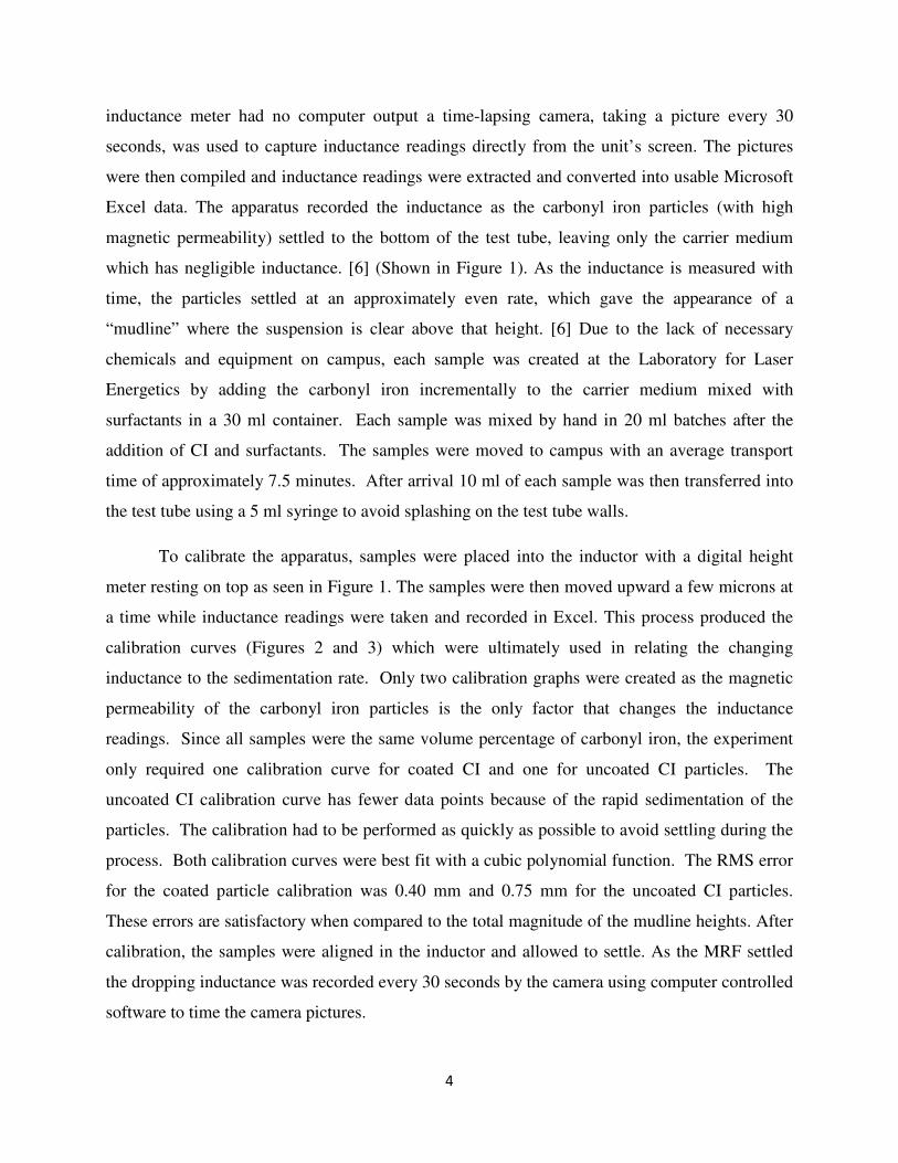
inductance to the sedimentation rate. Only two calibration graphs were created as the magnetic
permeability of the carbonyl iron particles is the only factor that changes the inductance
readings. Since all samples were the same volume percentage of carbonyl iron, the experiment
only required one calibration curve for coated CI and one for uncoated CI particles. The
uncoated CI calibration curve has fewer data points because of the rapid sedimentation of the
particles. The calibration had to be performed as quickly as possible to avoid settling during the
process. Both calibration curves were best fit with a cubic polynomial function. The RMS error
for the coated particle calibration was 0.40 mm and 0.75 mm for the uncoated CI particles.
These errors are satisfactory when compared to the total magnitude of the mudline heights. After
calibration, the samples were aligned in the inductor and allowed to settle. As the MRF settled
the dropping inductance was recorded every 30 seconds by the camera using computer controlled
software to time the camera pictures.

5
Figure 1: Experimental Set-up
Figure 2: Calibration curve for the zirconia coated carbonyl iron particles
6
Figure 3: Calibration curve for uncoated carbonyl iron particles
3. Results:
The inductance of each sample was measured over a period of approximately an hour after which
the samples had all settled to a constant reading where the mudline was below the inductor itself.
Figure 4 shows the inductance vs. time for each sample. The initial inductance readings are
similar for each of the coated samples (1-4) and slightly higher for the uncoated particles
(samples 5-6). This is due to the slight difference in magnetic permeability between coated and
uncoated particles at the same volume percentage (15 vol%). [1] Each of the samples in Figure 4
has non-linear initial and final regions separated by a linear region. These non linear regions
were observed in previous sedimentation experiments which measured the change in inductance
through the varying magnetic permeability of the settling particles. They are attributed to “edge
effects” as the mudline moves through the top and bottom of the inductor. [6]
Figure 5 shows the cropped results after applying the calibration curves to convert from
inductance to mudline height and removing the non-linear regions from each sample. Linear fits
were applied to each sample and the mudline sedimentation rates were extracted as the slope of
the linear sedimentation region. The samples did not all have the same starting height, which was
difficult to control when setting up each test tube. However, the slopes of each linear fit were
unaffected by the starting height. The RMS values for the linear fit were all satisfactory,
approximately two orders of magnitude less than the mudline height magnitudes. A summary of
these results can be found in table 2.

7
Table 2: Summary of Sedimentation Results
Sample Composition
Linear Sedimentation
Rate (mm/sec)
RMS from
Linear Fit
(mm)
Initial
pH
15 vol% Zirconia coated Carbonyl Iron w/ 85
vol% DI Water 0.0134 0.32 7.1
15 vol% Zirconia coated Carbonyl Iron, 1
vol% DAC, 2 vol% Glycerol, 82 vol% DI
Water
0.0109 0.31 7.3
15 vol% Zirconia coated Carbonyl Iron, 1
vol% Glacial Acetic Acid, 84 vol% DI Water 0.0114 0.10 3.17
15 vol% Zirconia coated Carbonyl Iron, 1
vol% DAC, 2 vol% Glycerol, 1 vol% Glacial
Acetic Acid, 81 vol% DI Water
0.0124 0.13 4.42
15 vol% Uncoated Carbonyl Iron, 85 vol% DI
Water 0.0453 0.36 7.45
15 vol% Uncoated Carbonyl Iron, 1 vol%
DAC, 2 vol% Glycerol, 82 vol% DI Water 0.0243 0.49 5.22

8
Figure 4: Uncropped Inductance vs Time for all samples
Figure 5: Cropped Linear Sedimentation Results
9
4. Discussion/Conclusions
Several factors contributed to the modification of sedimentation rates achieved through pH
control and the addition of DAC and glycerol. Both of the uncoated samples had higher
sedimentation rates than any of the zirconia coated samples. It has been shown that bi-disperse
suspensions that combine nano-sized particles with micron-sized particles are more stable and
have slower sedimentation rates. [6] The zirconia coated carbonyl iron suspensions have a small
volume percentage of nano-zirconia particles suspended amongst the CI that resulted from the
coating process. [1] This large disparity in sedimentation rates between the coated and uncoated
carbonyl iron suspensions can be attributed to the mono-disperse nature of the uncoated particle
suspensions.
The sedimentation and rheological behavior of a particle suspension is highly dependent
on the electro-chemical repulsive forces which result from the interaction between electrolytes
adsorbed to the surface material of the suspended particle and the composition of the bulk carrier
fluid. [8] A separation of charge exists at the surface of shear, which separates the more-
concentrated adsorbed layer of electrolytes in solution from the typical electrolyte concentration
throughout the bulk carrier solution. This forms an electric potential at the surface of shear
known as the zeta potential of the surface material. A high magnitude of zeta potential implies
that particles will be well dispersed from electro-chemical repulsive forces. [3] Since zeta
potential is a function of the electrolyte concentration in the bulk carrier medium, it can be raised
or lowered through pH modification via the addition of an acid or base. At the pH where a zeta
potential of zero is reached, termed the Iso-electric point (IEP), the particles will experience no
repulsive forces and experience attraction from short range van der walls forces causing
agglomeration which should increase sedimentation rates. [5] Thus the IEP was examined in
each of the samples to determine the electro-chemical stability of each sample. In sample 5, the
IEP for uncoated carbonyl iron particles was experimentally determined at a pH of 5.45. [7] The
initial pH for sample 1 was 7.45, a difference of 2 from the IEP. For comparison, sample 1,
which was merely zirconia coated carbonyl iron suspended in DI water, has an IEP of
approximately 7.2. This is very close to the measured pH of 7.1, implying that the sample #4
was experiencing a high degree of agglomeration as seen at near neutral pH regions of several
zirconia suspensions. [1] This demonstrates the strength of a bi-disperse system at reducing

10
sedimentation rates as even a highly agglomerated bi-disperse system (sample 1) settled more
slowly than a less-agglomerated mono-disperse system (sample 5) when measured at the same
carbonyl iron volume concentration.
Aside from pH control, the addition of surfactants is another way to improve the stability
of a suspension. It can be seen that the addition of DAC and glycerol to Sample #6, slowed the
sedimentation rate by 46%, demonstrating the effectiveness of the surfactants at providing
repulsive forces between the carbonyl iron particles. The addition of DAC and glycerol was also
successful in reducing the sedimentation rate of the zirconia coated suspension (as seen in
sample 2) by 19%.
Acetic acid was added to samples 3 and 4 (zirconia coated samples) to modify the zeta
potential of each suspension. Sample 3 contained only zirconia coated carbonyl iron and water,
for which the IEP is around 7.2. [9] The acid lowered the pH to 3.17, improving the stability of
suspension as can be demonstrated by the 15% reduction in sedimentation rate compared to the
acid-less sample 1. Sample 4 contained DAC and Glycerol as surfactants as well as acetic acid
to manipulate the surface chemistry of the suspension. The IEP for a zirconia coated carbonyl
iron suspension with DAC and glycerol has been identified in previous work at a pH of
approximately 4. [9] Unfortunately, the addition of acetic acid moved the pH to 4.42, very near
the IEP of the suspension. This caused agglomeration and increased the sedimentation rate of
the suspension, only reducing the sedimentation rate by 7.5% from sample 1. In future
experiments, the sedimentation rate of a basic suspension with zirconia coated carbonyl iron
particles, DAC, and Glycerol should be examined to move away from the IEP.
A possible source of error when identifying the sedimentation rates in the samples was in
the difficulty of starting with a uniformly dispersed suspension when inductance measurements
first began. Although the samples all had approximately equal times between creation and
measurement, the samples were all shaken by hand, thus the level of dispersion was difficult to
control or quantify. This may be the reason why there are such disparities in initial inductances
and mudline heights in figure 4 and 5. A more rigid and prescribed mixing process may create
more consistent results.

11
In conclusion, these results imply that the most important factor in reducing
sedimentation in low volume concentration carbonyl iron suspensions is through the use of a bi-
disperse system. The addition of DAC and Glycerol as surfactants had a larger effect at reducing
the sedimentation rates than zeta potential manipulation through the addition of acid alone. The
combined use of surfactants and pH control should allow for a higher degree of sedimentation
rate reduction than demonstrated in this experiment, as a base should be used to move away from
the suspension’s natural IEP. Further experimentation should be performed to verify this
hypothesis.
5. References:
[1] S. Shafrir, H. Romanofsky, M. Skarlinski, M. Wang, C. Miao, S. Salzman, T. Chartier, J.
Mici, J. Lambropoulos, R. Shen, H. Yang, and S. Jacobs, "Zirconia-coated carbonyl-iron-
particle-based magnetorheological fluid for polishing optical glasses and ceramics," Appl. Opt.
48, 6797-6810 (2009).
[2] J. DeGroote, A. Marino, J. Wilson, A. Bishop, J. Lambropoulos, and S. Jacobs, "Removal
rate model for magnetorheological finishing of glass," Appl. Opt. 46, 7927-7941 (2007).
[3] Zhongwu Zhou, Peter J. Scales, David V. Boger, Chemical and physical control of the
rheology of concentrated metal oxide suspensions, Chemical Engineering Science, Volume 56,
2901-2920 (2001).
[4] C.Miao, “Frictional Forces in Material Removal for Glasses and Ceramics using
Magnetorheological Finishing,” Ph.D Disseration, University of Rochester, Rochester, NY
(2010).
[5] G. Ngatu, N. Wereley, “Viscometric and Sedimentation Characterization
of Bidisperse Magnetorheological Fluids,” IEEE TRANSACTIONS ON MAGNETICS, VOL.
43, NO. 6, (2007).
[6] L. S. Chen and D. Y. Chen, “Permalloy inductor based instrument that measures the
sedimentation constant of magnetorheological fluids,” Rev. Sci. Instrum. 74, 3566 (2003),
DOI:10.1063/1.1581356
[7] J.L. Arias a, V. Gallardo a, F. Linares-Molinero a, A.V. Delgadob, “Preparation and
characterization of carbonyl iron/poly(butylcyanoacrylate)core/shell nanoparticles,” Journal of
Colloid and Interface Science 299 (2006) 599–607 (2005).
12
[8] Bergstrom, Lennart. Handbook of applied surface and colloid chemistry. John Wiley & Sons
Inc, 2002. 202-48. Print.
[9] M. Skarlinski and S. Jacobs, “Modifying the Rheological Properties of Zirconia Coated
Carbonyl Iron Suspensions through Acid-Base Titration and the addition of Di-Ammonium
Citrate,” IDOC Conference Proceedings (2010).