
SEDEX MODEL 80LT - KNAUER · use any equipment that can cause sparks in the same room as the ......
88
SEDEX MODEL 80LT LOW TEMPERATURE EVAPORATIVE LIGHT SCATTERING DETECTOR OPERATOR’S MANUAL SEDERE, S.A.S PARC VOLTA-BP 27 9, Rue Parmentier 94141 Alfortville Cedex FRANCE Telephone +33 1 45 18 05 18 Fax + 33 1 45 18 05 25 Part Number 81000 Rev. 3 February 2011
Transcript of SEDEX MODEL 80LT - KNAUER · use any equipment that can cause sparks in the same room as the ......

SEDEX MODEL 80LT
LOW TEMPERATURE EVAPORATIVE LIGHT SCATTERING DETECT OR
OPERATOR’S MANUAL
SEDERE, S.A.S PARC VOLTA-BP 27
9, Rue Parmentier 94141 Alfortville Cedex
FRANCE
Telephone +33 1 45 18 05 18 Fax + 33 1 45 18 05 25
Part Number 81000 Rev. 3 February 2011
This product is covered by the following: Patent Application Number: 97 16240 (date Dec. 22, 1997) Patent Application Number: FR 98 15518 (date Dec. 9, 1998) Patent Application Number: US 6, 148,661 (date Nov. 21, 2000) Patent Application Number: FR 01 09 202 (date Jul. 11, 2001) Patent Application Number: EP 02 290 580.6 (date Mar. 8, 2002) Patent Application Number: FR 03 01652 (date Feb. 12, 2003) Patent Application Number: US 2003/0086092 A1 (date May 8, 2003) Patent Application Number: FR 03 13706 (date Nov. 24, 2003) Patent Application Number: EP 1 447 663 A1 (date Aug. 18, 2004) Patent Application Number: US 6, 936, 174 B2 (date Aug. 30, 2005) Patent Application Number: FR 06 50372 (date Feb. 2, 2006) Patent Application Number: FR 07 52752 (date Jan. 19, 2007) Patent Application Number: FR 2007/050669 (date Jan. 22, 2007) SEDERE and SEDEX are trademarks of S.E.D.E.R.E. S.A.S. Parafilm is a trademark of American National Can Co. Teflon is a trademark of E.I. Dupont de Nemours, Inc. Tygon is a trademark of the Norton Corporation All information in this manual is subject to change without notice and does not represent a commitment on the part of S.E.D.E.R.E S.A.S. Please consult S.E.D.E.R.E S.A.S if you suspect any error or omission. S.E.D.E.R.E S.A.S believes that the information in its user manuals is accurate as the date of publication. Copyright 2003 S.E.D.E.R.E. S.A.S. All rights reserved. No part of this manual may be reproduced or transmitted in any form or by any means without the written permission of S.E.D.E.R.E. S.A.S. Printed in France

SEDEX Model 80LT iii Evaporative Light Scattering Detector
The following precautions should be followed to minimize the possibility of personal injury and/or damage to property when using the Sedex Model 80 Low Temperature Evaporative Light-Scattering Detector.
1) Read the Operator’s Manual thoroughly before you use the detector and keep this manual for future reference.
2) Maintain a well ventilated laboratory. If the mobile phase contains a volatile organic solvent, ensure that the laboratory is well ventilated so that a build-up of vaporized solvent cannot occur.
3) Avoid open flames and sparks. Do not use an open flame and do not use any equipment that can cause sparks in the same room as the instrument.
4) The detector must be plugged into a grounded power line. Make certain that all parts of the instrument are properly connected to a common ground.
5) If the mobile phase includes an organic solvent, use an inert gas to nebulize the mobile phase.
6) The exhaust from the detector should be vented into a fume hood or similar system. Make certain that the output gas does not escape into the laboratory. Take in consideration any solvent filter that could be required by your local environmental laws.
7) The gas pressure should not exceed 4.5bar (67 psi). Make certain that the gas flow is maintained while the mobile phase flows through the detector. If the gas flow is interrupted for extended periods of time, organic solvents could possibly damage the pressure sensor and/or the photomultiplier
8) Do not use corrosive materials (non-exhaustive example: Tetrahydrofuran) that could damage the inner metal surfaces (stainless steel) of the detector.
9) Do not use any liquid or gas (non-exhaustive examples: pure oxygen or
hydrogen) that support combustion under temperatures reached by the detector.
10) Access inside the instrument is restricted to a suitably skilled and
competent technician.
11) Do not remove the optical head or the photomultiplier tube while the instrument is powered up. This can destroy the photomultiplier.
Warnings and Safety Precautions
Warnings and Safety Precautions
iv SEDEX Model 80LT Evaporative Light Scattering Detector
12) The siphon overflow tube must contain liquid at all times.
13) Do not disassemble the nebulizer or touch any components inside the nebulization chamber. This can lead to the deposition of contaminants that could affect the signal.
14) Do not adjust any components inside the detector unless specifically authorized to do so by your dealer.
15) If the instrument is used in a manner not specified by the manufacturer,
the protection ensured by the instrument can be ineffective. 16) The user is responsible for decontamination if hazardous material is
spilled on or in the instrument. 17) The user is responsible for detector end of life
recycling. You must not discard this electrical/electronic product in domestic household waste. This product is classed as a Monitoring and Control instrumentation product. Detector internal parts present no danger for recycling. Make certain than detector has been cleaned to ensure no solvent or solute can remain in detector drift tube.
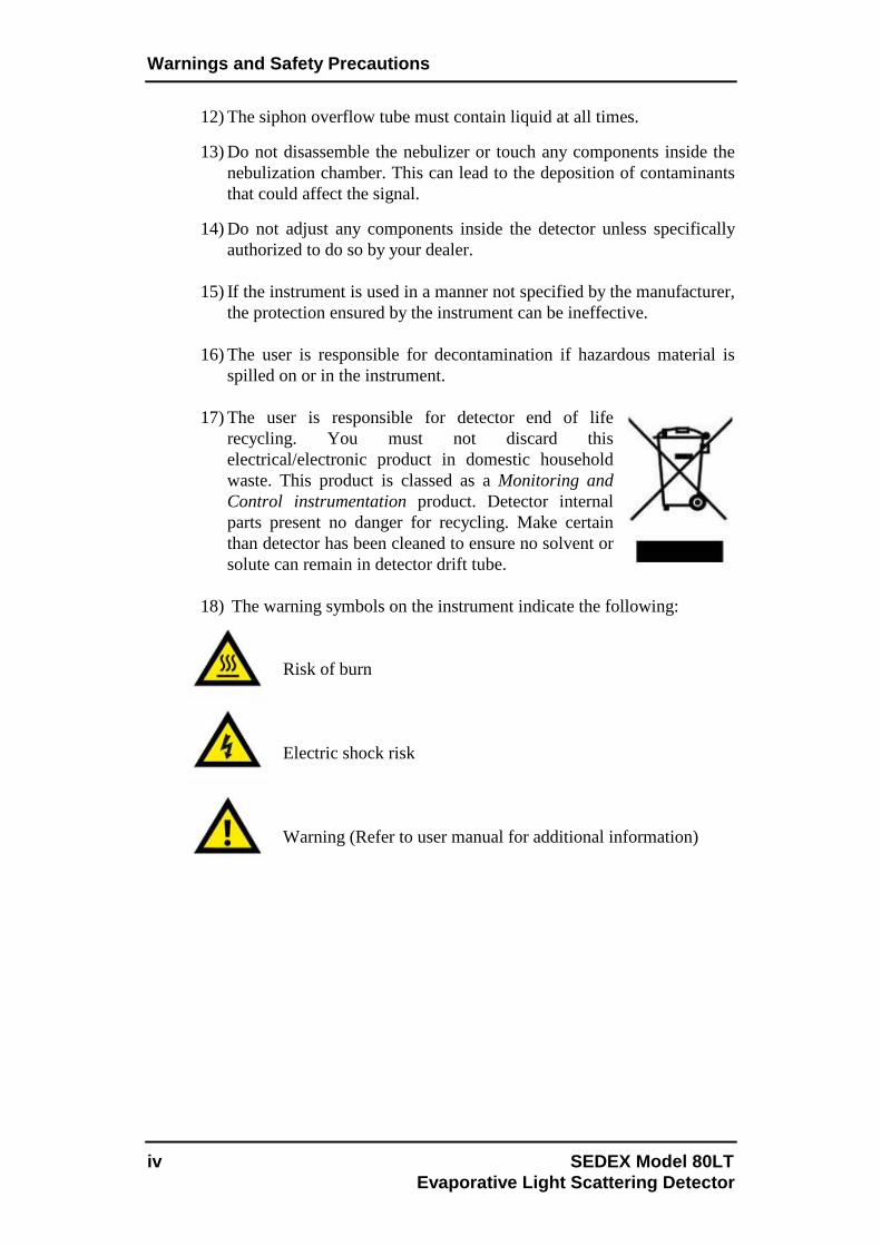
18) The warning symbols on the instrument indicate the following:
Risk of burn Electric shock risk Warning (Refer to user manual for additional information)

SEDEX Model 80LT v Evaporative Light Scattering Detector
Warnings and Safety Precautions ................... ...................................... iii
1 Introduction .................................... .................................................. 1-1 1.1 The Low Temperature Evaporative Light-Scattering Detector ............. 1-1 1.2 Principle of Operation ........................................................................... 1-2
1.2.1 Nebulization .............................................................................. 1-3 1.2.2 Evaporation of the Solvent ....................................................... 1-4 1.2.3 Detection ................................................................................... 1-5
1.3 Content of this Manual .......................................................................... 1-6 1.4 For Additional Information ................................................................... 1-7 1.4 S.E.D.E.R.E Information ....................................................................... 1-8
2 Installation of the Detector .................... ......................................... 2-1 2.1 Overview ............................................................................................... 2-1 2.2 Lifting and Carrying the Detector .......................................................... 2-2 2.3 Unpacking the Detector ......................................................................... 2-3 2.4 Laboratory Requirements ...................................................................... 2-3
2.4.1 Power Requirements ................................................................. 2-3 2.4.2 Gas Requirements ..................................................................... 2-3 2.4.3 Exhaust Venting and Drain Requirements ............................... 2-4 2.4.4 Location of the Detector in the Laboratory ............................... 2-5 2.4.5 Environmental Conditions ........................................................ 2-5
2.5 Installation of the Unit ........................................................................... 2-6 2.5.1 Gas Supply ................................................................................ 2-6 2.5.2 Vent the Exhaust Line to a Fume Hood .................................... 2-7 2.5.3 Electrical Connections .............................................................. 2-8 2.5.4 Installing the Nebulizer/Glass Chamber Assembly ................ 2-10 2.5.5 Connecting the Siphon Overflow ........................................... 2-11 2.5.6 Connecting the Nebulization Gas to the Nebulizer ................ 2-12 2.5.7 Connecting the Column .......................................................... 2-12 2.5.8 Powering Up the Unit ............................................................. 2-12
3 Start-up Procedure .............................. ............................................ 3-1 3.1 Overview ............................................................................................... 3-1 3.2 The Control Panel .................................................................................. 3-1
3.2.1 The Digital Display ................................................................... 3-1 3.2.2 The User Interface..................................................................... 3-3
3.2.2.a The Status Screen ....................................................... 3-3 3.2.2.b The Offset Screen ....................................................... 3-3 3.2.2.c The Temperature/Gain Screen ................................... 3-4 3.2.2.d The Autozero Offset Screen ....................................... 3-4 3.2.2.e The Noise Filter/Pressure Unit Screen ...................... 3-5 3.2.2.f The LED Screen ......................................................... 3-6 3.2.2.g The Gas Valve Screen ................................................ 3-6 3.2.2.h The Power Down Screen ........................................... 3-7
Table of Contents

Table of Contents
vi SEDEX Model 80LT Evaporative Light Scattering Detector
3.2.2.i The Total Lifetime Elapsed Screen ............................ 3-8 3.2.2.j The Serial Number Screen ......................................... 3-8 3.2.2.k The Firmware Screen ................................................ 3-9 3.2.2.l The Factory Menu Code Screen ................................ 3-9
3.3 Initial Test Procedures ......................................................................... 3-10 3.3.1 Preliminary Activities ............................................................. 3-10 3.3.2 Electronic Noise Test .............................................................. 3-11 3.3.3 Background Noise (Stray Light) Test ..................................... 3-11 3.3.4 Solvent Noise Test .................................................................. 3-12 3.3.5 Column Noise Test ................................................................. 3-13
4 Operating the Detector .......................... .......................................... 4-1 4.1 Overview ............................................................................................... 4-1 4.2 Preparing the Detector for Operation .................................................... 4-1 4.3 Auto-zeroing the Detector ..................................................................... 4-2
4.3.1 Manual Auto-zeroing of the Detector ....................................... 4-2 4.3.2 External Auto-zeroing of the Detector...................................... 4-2
4.4 Routine Operation of the Detector ........................................................ 4-3 4.5 Optimizing Performance ....................................................................... 4-3
4.5.1 Selecting the Optimum Temperature ........................................ 4-3 4.5.2 Optimizing the Mobile Phase ................................................... 4-5 4.5.3 Sample Pretreatment ................................................................. 4-6 4.5.4 Column Treatment .................................................................... 4-6 4.5.5 Optimizing the Noise Filter ...................................................... 4-6
4.6 Powering Down and Shutting Down the Detector ................................ 4-7
5 Maintenance and Troubleshooting ................. ............................... 5-1 5.1 Overview ............................................................................................... 5-1 5.2 Maintenance .......................................................................................... 5-1 5.3 Troubleshooting ..................................................................................... 5-3
5.3.1 General Troubleshooting Information ...................................... 5-3 5.3.2 Initial Troubleshooting Activities ............................................. 5-4 5.3.3 Perform the Noise Tests ............................................................ 5-4 5.3.4 Specific Detector Troubleshooting .......................................... 5-4 5.3.5 Nebulizer Cleaning and Replacement Procedures .................... 5-6 5.3.6 Gas Flow Problems ................................................................... 5-9
5.4 Cleaning and Decontamination ............................................................. 5-9 5.4.1 Instrument Cleaning .................................................................. 5-9 5.4.2 Instrument Decontamination................................................... 5-10
5.5 Light Source Exchange ........................................................................ 5-10
Appendix 1: Specifications ........................ ....................................... A1-1 Appendix 2: Spare Parts List ...................... ...................................... A2-1 Appendix 3: Standard Operating Procedure and I.Q./O .Q./P.Q. ..... A3-1 Appendix 4: Application Notes ..................... .................................... A4-1 Appendix 5: Drivers for SEDEX Model 80LT Detector . ................... A5-1 Index ............................................. ........................................................... I-1

SEDEX Model 80LT 1-1 Evaporative Light Scattering Detector
1.1 The Low Temperature Evaporative Light-Scatterin g Detector The ELSD 80 Low Temperature Evaporative Light-Scattering Detector (Figure 1-1) is designed to detect compounds in the eluent from High Performance Liquid Chromatography (HPLC), Gel Permeation Chromatography (GPC), preparative HPLC, Flash Chromatography or Counter Current Chromatography (CCC). It is capable of monitoring eluent flow rates from 100µL/min to 5mL/min. Evaporative Light-Scattering Detection is a nearly universal technique which can detect any non-volatile analyte. Unlike other types of detection mode such as UV Detection, it is not dependent on the absorption of radiation and is not affected by the absorption characteristics of the solvent. Thus, solvents which absorb UV radiation can be used. As the solvent is completely evaporated, a gradient can be performed to optimize the separation.
Figure 1-1: The SEDERE ELSD 80 Low Temperature Evap orative Light-Scattering Detector
The detector is controlled via the keypad and digital LCD display on the front panel. The analog signal output can be sent to a recorder, an integrator or a data station. As an alternative, the instrument can be controlled by an external computer using the RS-232 port. The detector includes a nebulization cell, an evaporation tube and a detection chamber. The evaporation tube is heated in order to evaporate the solvent.
1 Introduction

Chapter 1
1-2 SEDEX Model 80LT Evaporat ive Light Scattering Detector
1.2 Principle of Operation There are three discrete steps in the operation of the detector; nebulization of the eluent, evaporation of the solvent and detection of the compound(s) of interest (Figure 1-2).
NEBULIZATION →→→→ EVAPORATION →→→→ DETECTION
Figure 1-2: Schematic Diagram of an Evaporative Lig ht-Scattering Detector
Nebulization involves the conversion of the eluent into a fine aerosol. This aerosol is directed to an evaporator to vaporize the solvent, then the mist is irradiated by a light source and the scattered light is measured by a photomultiplier; which is related to the concentration of the compound of interest in the sample. A cross sectional view of the instrument is presented in Figure 1-3.
Figure 1-3: Cross-sectional View of the Detector
Step 2: EVAPORATION
Step 1: NEBULIZATION
Step 3: DETECTION

Introduction
SEDEX Model 80LT 1-3 Evaporative Light Scattering Detector
1.2.1 Nebulization The eluent from the chromatograph is nebulized by the inlet gas (typically air or nitrogen). At the outlet of the nebulizer, the aerosol travels through a chamber. Large droplets in the aerosol are drawn to a siphon while the fine mist travels to the evaporation tube. The overall design of the nebulizer is shown in Figure 1-4 and the nebulization chamber is shown in Figure 1-5. Three different nebulizers are available to optimize performance of the detector at different Liquid Chromatography flow rates (see Table 1-1). The user should select the nebulizer to best match the flow rate that will be used with the separation when the detector is ordered (the optimal range for each nebulizer is indicated in Table 1-1). Additional nebulizers are available can be easily installed as described in Section 5.3.5.
Nebulizer Flow Rate
Range Back Pressure - bar (with water)
Identifying Marks
Part Number
HPLC Nebulizer 100µL/min - 2.5mL/min
4 (1mL/min) Black Seal
2 Rings White Capillary
80003
Combinatorial Chemistry Nebulizer
1.0mL/min - 4.0mL/min
4 (1mL/min) Red Seal 1 Ring
White Capillary 80008
Flash Chromatography Nebulizer
100µL/min – 5mL/min
4 (1mL/min) Black Seal No Ring
White Capillary 80005
Table 1-1 Nebulizers for the ELSD 80 Low Temperatur e Evaporative
Light-Scattering Detector
Figure 1-4: Design of the Nebulizer
Ring
Coloured Seal
Gas inlet
Liquid inlet

Chapter 1
1-4 SEDEX Model 80LT Evaporat ive Light Scattering Detector
Figure 1-5: Glassware Chamber 1.2.2 Evaporation of the Solvent A heated tube is used to evaporate the solvent. The exit of the heated tube leads directly into the detection chamber. In liquid chromatography, water and organic solvents with low boiling points are typically employed (e.g. CH3OH, CHCl3, CH3CN). A typical mobile phase for a reverse phase separation using Evaporative Light-Scattering Detection might be CH3OH/H2O (60/40) while a typical mobile phase for normal phase separation might be C6H14/CHCl3 (60/40). If acids, bases and salts are used to modify mobile phase to provide the desired separation, they should be able to be readily evaporated, sublimed or decomposed into gases in the evaporation tube. Mobile phase modifiers that are commonly used when an Evaporative Light-Scattering Detector is employed include NH4OH, (C2H5)3N, NH4 Acetate, NH4 Formate, HCOOH, CH3COOH and CF3COOH.

Introduction
SEDEX Model 80LT 1-5 Evaporative Light Scattering Detector
1.2.3 Detection The carrier gas transports the microparticles from the heating tube into the detection chamber (Figure 1-6).
Figure 1-6: The Detection Chamber The detector chamber contains a Light Emitting Diode (L.E.D.) and a photomultiplier that is positioned at an angle of 120° with respect to the light beam (Figure 1-6). When the carrier gas contains microparticles, the light is scattered and is detected by the off-axis photomultiplier. The intensity of the scattered light is a function of the mass of the scattering particles and generally follows an exponential relationship, which is shown in equation 1-1.
I = k mb (1-1)
where: I is the intensity of light m is the mass of the scattering particles k and b are constants
A plot of log I versus log m provides a linear response. The values of the constants (k and b) are dependent on a variety of experimental conditions (e.g. the temperature and the nature of the mobile phase). An inlet to provide additional gas is located immediately before the detector chamber to provide a concentric shield for the carrier gas. This serves to eliminate diffusion of the carrier gas and eliminate contamination of the detection chamber.
LED
Detection Chamber
Photomultiplier
Light Trap Additional Gas

Chapter 1
1-6 SEDEX Model 80LT Evaporat ive Light Scattering Detector
1.3 Content of this Manual This manual is designed to describe the installation, operation, maintenance and troubleshooting of the SEDEX ELSD 80 Low Temperature Evaporative Light-Scattering Detector. It includes:
• Chapter 2 - Installation of the Detector, describes suitable laboratory conditions for the detector and includes information about interfacing the detector to other devices.
• Chapter 3 - Start-up Procedure, describes the role of the various
controls and displays on the detector. In addition, this chapter discusses a number of activities to prepare the unit for routine data collection.
• Chapter 4 - Operating the Detector, describes how to operate the
Low Temperature Evaporative Light-Scattering Detector. It includes information about starting the unit on a routine basis, collecting data and shutting the unit down.
• Chapter 5 - Maintenance and Troubleshooting, describes a series of
activities that should be performed on a periodic basis to ensure maximum performance. In addition, this chapter includes a protocol that can be used to determine the cause of problems that are observed with the instrument.
• A series of appendices are provided which include product
specifications, a list of spare parts, Standard Operating Procedures, applications and drivers.

Introduction
SEDEX Model 80LT 1-7 Evaporative Light Scattering Detector
1.4 For Additional Information The detector is used as a part of an HPLC system and manuals supplied with other components contain important information. For additional information about Evaporative Light-Scattering Detection, the following articles may be of interest:
1. Stolyhwo, A.; Colin, H.; Martin, M.; Guiochon, G. J. Chromatogr., Study of the qualitative and quantitative properties of the light-scattering detector. 1984, 288, 253.
2. Dreux, M.; Lafosse, M.; Morin-Allory, L. LC-GC Intl., The evaporative light scattering detector-A universal instrument for non-volatile solutes in LC and SFC. 1996, 9 (3), 148 and references 1, 3, 11, 22, 23 cited therein.
3. Trathnigg, B.; Kollroser, M. J. J. Chromatogr. A, Liquid chromatography of polyethers using universal detectors. V. Quantitative aspects in the analysis of low-molecular-mass poly(ethylene glycol)s and their derivatives by reversed-phase high-performance liquid chromatography with an evaporative light scattering detector. 1997, 768, 223.
4. Nordbäck, J.; Lundberg, E.; Christie, W.W., Mar. Chem., Separation of lipid classes from marine particulate material by HPLC on a polyvinyl alcohol-bonded stationary phase using dual-channel evaporative light scattering detection. 1998, 60, 165.
5. Practical SFC and SFE, edited by M. Caude and D. Thiebaut. Chapter 5d ELS detection in SFC p 201-218, M. Lafosse, Harwood Academic Publishers, The Netherlands, 1999.
6. Fang, L.; Wan, M.; Pennachio, M.; and Pan, J., J. Comb. Chem., Evaluation
of ELSD for combinatorial library quantitation by RP-LC. ELSD as a universal detector for rapid quantitation in combinatorial chemistry. 2000(2), 254.
7. Sims, J.L., Chromatographia, Proposed performance qualification and calibration method for evaporative light scattering detectors. 2001, 53, 401.
8. Petritis, K.; Dessans, H.; Elfakir, C.; Dreux, M., LC GC Eur., Volatility evaluation of mobile-phase/electrolyte additives for mass spectrometry. 2002, 15, 98.
9. Carbohydrate Analysis by Modern Chromatography and Electrophoresis. Edited by Ziad El Rassi. Chapter 30 Carbohydrate Analysis by LC and SFC using ELS detection, M. Lafosse and B. Herbreteau; Journal of Chromatography Library, Vol. 66, p1101-1134; Elsevier, 2002.
10. Megoulas N.C. and Koupparis M.A., Critical Reviews in Analytical
Chemistry, Twenty Years of Evaporative Light-Scattering Detection. 2005, 35, 301.
A more complete bibliography on Evaporative Light-Scattering Detection applications can be obtained from your local distributor.

Chapter 1
1-8 SEDEX Model 80LT Evaporat ive Light Scattering Detector
1.5 S.E.D.E.R.E Location Information S.E.D.E.R.E has two locations in France:
• Administration is located in Paris. • Production is located in Orléans.
S.E.D.E.R.E, S.A.S. 9 Rue Parmentier Parc Volta - BP 27 F-94141 Alfortville, France Phone: 33 (0)1 45 18 05 18 Fax: 33 (0)1 45 18 05 25 e-mail: [email protected] S.E.D.E.R.E Parc du Moulin 841, Boulevard Duhamel du Monceau F-45160 Olivet, France Please, visit our web site for additional information or assistance:
www.sedere.com

SEDEX Model 80LT 2-1 Evaporative Light Scattering Detector
2.1 Overview This chapter describes how the laboratory should be prepared to optimize the performance of the SEDEX ELSD 80 Low Temperature Evaporative Light-Scattering Detector and indicates how the unit is interfaced to other devices such as the column and the data recording device. When you have successfully installed the unit, refer to Chapter 3 for start-up procedures. The detector is provided in three different configurations as described in Table 2-1. The first configuration (with HPLC nebulizer) is dedicated to standard HPLC applications, the second one (with CC nebulizer) is dedicated to Combinatorial Chemistry using high eluent flow rates and the third one (with FLASH nebulizer) is dedicated to Flash Chromatography. All models can be provided with RS-232 activated (communication option) to be fully controlled by PC via drivers for Chromatography Software or not. The communication option can be activated afterwards. An accessory kit includes the components indicated in Table 2-2.
Detector Version Communication Option 115V/60 Hz 230V/50 Hz
ELSD 80 with a HPLC Nebulizer 100µL/min – 2.5mL/min
Without With
80001 80001S
80000 80000S
ELSD 80 with a CC Nebulizer 1mL/min – 4mL/min
Without With
80401 80401S
80400 80400S
ELSD 80 with a FLASH Neb. 100µL/min – 5mL/min
Without With
80501 80501S
80500 80500S
Table 2-1: ELSD 80 Low Temperature
Evaporative Light-Scattering Detector Versions Quantity Part Number Description 1 See Table 2-3 Nebulizer 1 85009-10 Glass Cell 1 81000 Operator’s Manual (this manual) 1 80097 Start-up kit consists of:
1 Power cable 1 Autozero cable 1 External event cable 1 Signal cable 1 RS-232 cable (if Software Option activated) 6 mm O.D. gas tubing (2 meters + 1 meter sets) 1 set of replacement fuses
Table 2-2: Components Shipped with the ELSD 80
Low Temperature Evaporative Light-Scattering Detect or
2 Installation of the Detector

Chapter 2
2-2 SEDEX Model 80LT Evaporative Light Scattering Detector
Nebulizer Flow Rate
Range Back Pressure - bar (with water)
Identifying Marks
Part Number
HPLC Nebulizer 100µL/min - 2.5mL/min
4 (1mL/min) Black Seal
2 Rings White Capillary
80003
Combinatorial Chemistry Nebulizer
1.0mL/min - 4.0mL/min
4 (1mL/min) Red Seal 1 Ring
White Capillary 80008
Flash Chromatography Nebulizer
100µL/min - 5mL/min
4 (1mL/min) Black Seal No Ring
White Capillary 80005
Table 2-3: Nebulizers for the ELSD 80 Low Temperatu re
Evaporative Light-Scattering Detector
SEDERE provides a wide range of accessories available (e.g. Gas Regulator with Filter and Manometer [part number 45100]) to support the operation of the detector. A complete listing of all spare parts and accessories is included in Appendix 2. 2.2 Lifting and Carrying the Detector
Note: To ensure safe transport and avoid bodily injury, make certain that the detector is lifted by two persons.
Once the instrument is unpacked, ensure that no cables or tubing are connected when you carry the instrument. The detector should be lifted by the bottom (e.g. place your hands under the instrument). Two persons are needed to ensure easy transport and avoid bodily injury (Figure 2-1).
Figure 2-1: Carrying the Detector
Do NOT Lift Here
Carry Here
Do NOT Lift Here
Carry Here

Installation of the Detector
SEDEX Model 80LT 2-3 Evaporative Light Scattering Detector
2.3 Unpacking the Detector Carefully inspect all cartons and components against the packing slip to ensure that you have received all items. The nebulizer cell assembly and nebulizer are packed in a separate container for shipping. If there is any damage to a carton or to any components or if any component appears to be missing, contact both the shipping agent and your local distributor immediately. If there is any evidence that the main unit has been damaged, do not plug the unit into the power line. Contact your local distributor immediately. It is recommended that the shipping carton be retained as it can be used if it should become necessary to transport the detector. 2.4 Laboratory Requirements 2.4.1 Power Requirements The detector is configured for 115V AC/60Hz or 230V AC/50Hz input power (depending on the country to which it is shipped). Ensure that the voltage value indicated on the power connector on the rear panel corresponds to the line voltage in your facility. The detector requires 115V/1.8A or 230V/1.7A. Check that the power lines can provide sufficient current. The detector must be connected to a properly grounded three prong plug to ensure proper operation of the instrument. If a two prong outlet is used, make certain that the ground wire is used to ground the instrument. It is recommended that all components of the HPLC system are connected to a common ground. The detector should not be connected to an electrical line which also serves units with a large power drain or which may be subject to power surges. Such units include refrigerators, ovens, centrifuges and fume hoods. 2.4.2 Gas Requirements A supply of filtered, oil-free clean gas (e.g. N2 or air if aqueous mobile phase) is required to operate the detector. Pure gas is not required as gas is only a carrier vector for the solid particles (e.g. air from an air compressor is acceptable if un-reactive with analysis).
Chapter 2
2-4 SEDEX Model 80LT Evaporative Light Scattering Detector
The gas supply should include a pressure gauge. A filter (0.01µm) and manometer (part number 45100) is available as an option. Replacement filter cartridges are available as part number 45007. 2.4.3 Exhaust Venting and Drain Requirements The black exhaust tube from the detector can be cut and should be directed into a fume hood or exhaust vent. If a vacuum is used, it should be moderate so as to avoid turbulence in the glass cell siphon.
Note: Ensure that the ParafilmTM is removed from the exhaust tube before installing the unit.
The drain tubing must be directed to an appropriate container regarding to the solvent nature. The user is responsible for decontamination or recycling of any residue, regarding to the local authorities environmental requirements. Please check your local regulatory authorities for health and safety requirements.
Do not use gases that support combustion with combustible solvents!
The exhaust and drain should not be allowed to enter the laboratory atmosphere and any appropriate accessory (e.g. solvent filter) should be disposed of in a manner that meets the local regulatory authorities for health and safety requirements.
The vacuum must be moderate to avoid turbulence in the glass cell siphon or liquid spilled into the evaporation tube. Avoid loops or bends in the black exhaust tubing which could create condensation traps resulting in bad measurement results. If gas from the hood enters the detector (i.e. a negative pressure exists between the detector and the fume hood), it is possible that foreign material from the hood could contaminate the detector.
Install the drain tubing (it can be cut) in a way to the siphon outlet aligns straight to the waste container –without loops or bends-, so that the waste liquid flows smoothly through the drain tubing. Fix the drain tubing at the inlet of the waste container so that the end of the drain tubing never dives into the liquid in the container.

Installation of the Detector
SEDEX Model 80LT 2-5 Evaporative Light Scattering Detector
2.4.4 Location of the Detector in the Laboratory All components of the system (e.g. HPLC pumps, detector) should be located on a sturdy table. The detector should be placed in an area that is free from drafts or significant temperature changes. Do not place it near air conditioning vents, windows, ovens, etc. When placing the detector in the laboratory, access to the power to disconnect the device (the appliance coupler or the mains plug) must be kept accessible at all time.
Note: The detector should be placed close to the outlet of the column to minimize extra-column band broadening which would reduce the resolution of the chromatographic separation.
Note: As a destructive detector, the ELSD should be the last one in the flow path or can be used with a splitter.
2.4.5 Environmental Conditions This instrument has been designed for the following conditions:
• Use inside buildings • Altitude below 2000 meters • Ambient temperature from 5°C to 40°C • Maximum humidity of 80% for temperatures under 31°C, with linear
decrease down to 50% at 40°C • Maximum variations for main power voltage: ±10% from nominal
voltage. • Transitory overvoltage of class II • Pollution degree: 2

Chapter 2
2-6 SEDEX Model 80LT Evaporative Light Scattering Detector
2.5 Installation of the Unit 2.5.1 Gas Supply The unit is connected to the gas supply via the 6.0mm plastic tubing (supplied) using the fitting on the upper left corner of the supply panel on the back of the detector (Figure 2-2).
Figure 2-2: Supply Panel
The tubing should be cut and firmly inserted into the fitting as shown in Figure 2-3, after removing ParafilmTM from the detector gas inlet.
Figure 2-3: Inserting the Gas Inlet Tube Two pieces of tubing are provided. If you are using the instrument with an external filter, connect the gas source to the filter and then connect the filter to the back of the unit. Make certain that no tube damage or inappropriate installation could allow a gas leak in laboratory. To remove the gas inlet tube (if necessary); refer to Figure 2-4.
MAIN POWER Gas inlet 1V output
RS-232 Ext. events Ext. Autozero

Installation of the Detector
SEDEX Model 80LT 2-7 Evaporative Light Scattering Detector
Figure 2-4: Removal of the Gas Inlet Tube 2.5.2 Vent the Exhaust Line to a Fume Hood The black exhaust line on the back of the unit should be vented to a fume hood. Make certain that the fume hood withdraws gas from the detector (i.e. there should be a positive pressure between the detector and the hood). Verify that no tube damage or inappropriate installation could allow a gas leak in laboratory.
Install the vent tube so that it cannot become blocked or bent, or restrict the gas flow from the detector to the hood in any way. Avoid long tube installations in upward direction creating condensation dropping back into the detector. If an extension tube is required (i.e. the supplied tube is not long enough), a suitable length of ¾"ID of PVC tubing can be fitted over the exhaust tubing.
The vacuum must be moderate to avoid turbulence in the glass cell siphon or liquid spilled into the evaporation tube. Avoid loops or bends in the black exhaust tubing which could create condensation traps resulting in bad measurement results. If gas from the hood enters the detector (i.e. a negative pressure exists between the detector and the fume hood), it is possible that foreign material from the hood could contaminate the detector.
Chapter 2
2-8 SEDEX Model 80LT Evaporative Light Scattering Detector
2.5.3 Electrical Connections All electrical connections are made via the supply panel (Figure 2-2) on rear panel.
a) Connecting the Recorder/Integrator: If a recorder or integrator is employed, connect the recorder input to the 1V output terminal on the rear panel of the detector (Figure 2-2) and to the appropriate socket on the recorder/integrator.
b) Connecting the External Autozero:
If the external autozero function is to be employed, plug the cable that is supplied into the Ext Autozero socket on the detector (Figure 2-2) and to the appropriate socket on the controlling device (e.g. autosampler, pump, etc.). Refer to section 4.3.2 to operate external autozero signal.
c) Connecting the External Events Cable
If the external events functions are to be employed, plug the cable that is supplied into the appropriate socket on the back panel of the detector (Figure 2-2) and to the appropriate socket on the controlling device (e.g. autosampler, pump, etc.). The white cables are contact closure “output” cables that provide the ready/non-ready information to an external device. The detector will be in the “not-ready” mode (the contact will be in closed position) if any one of the following conditions is observed:
� The lamp is off. � The temperature is not at the indicated setpoint. � The temperature is at the indicated setpoint but is not stable. � The pressure is below 3.0bar.
Note: The controlled device electrical consumption mustn't exceed 20mA under 12V DC.
The blue cables are contact closure “input” cables that are used to power the unit down (see Section 3.2.2.h) via a signal from an external device to the detector.

Installation of the Detector
SEDEX Model 80LT 2-9 Evaporative Light Scattering Detector
d) RS-232 Port (Only for ELSD 80 Detector with Software RS-232
activated) If a personal computer is used with the detector, the detector should be connected to the computer via the RS-232 port using the supplied cable.
Note: Software drivers for a full LT-ELSD control are available for: EZChrom Elite™ (SEDERE part number 85090), ChemStation™ (SEDERE part number 85089), Xcalibur™ (SEDERE part number 85093), Clarity™ (The driver is part of Clarity from Versio n 3.0.2). This also avoids using an A/D converter by a direct connection to a free RS-232 COM port. Please refer to Appendix 5. In these cases, only two cables are then required: • RS-232 cable, to be connected between the detector and the computer RS-232 (avoid USB/RS-232 converter). • Autozero cable, to be connected for a “Start” information on the controlling device (e.g. autosampler). In this mode, the detector doesn’t proceed to an Autozero, it uses it as a signal synchronization for the driver. Please refer to Appendix 5. Not using the AutoZero connection for a “Start” information will impair the synchronization of the Signal and may not generate the final report and/or impair the retention time reproductibility.
e) Connecting the Power Cord
Place the ON/OFF switch to the OFF position and plug the power cord into the socket on the rear panel of the detector.
Do not turn on the power at this time.
The power cord of this detector contains three wires which must be connected to a grounded line. All components of the chromatographic system should be connected to a common ground. If a two wire outlet is used, make certain that an adapter is used to connect the third wire to ground.

Chapter 2
2-10 SEDEX Model 80LT Evaporative Light Scattering Detector
2.5.4 Installing the Nebulizer/Glass Chamber Assemb ly ParafilmTM is used to cover various openings inside the compartment, nebulizer and glassware to prevent dust particles from entering the detector during shipment.
Note: When installing the transparent black front cover, first fix its right side, and then push its left side. When removing the front cover, pull only its left side.
The installed Nebulizer/Glass Chamber assembly is shown in Figure 2-5.
Figure 2-5: Installing the Nebulizer/Glass Chamber Assembly To install the assembly:
a) Remove the ParafilmTM from all detector openings and from the nebulization cell (these coatings are used to prevent dust particles from entering the instrument during shipment).
b) Position the glass chamber as shown in Figure 2-5 and tighten the black
nut at the bottom. The glass chamber should be flush with the back wall as shown in Figure 2-6.
Union Column Bulkhead
Nut Glass chamber
Siphon Overflow
Nut
Nebulizer
Gas inlet Fitting
Gas one-way Valve

Installation of the Detector
SEDEX Model 80LT 2-11 Evaporative Light Scattering Detector
Figure 2-6: Fixing the Tip of Glass Chamber
c) Use the large black nut to position the nebulizer on the glass chamber. d) Screw the inlet fitting in the bulkhead on the left side of the compartment.
Special care must be taken when positioning this fitting. The nebulizer is terminated with a small piece of Teflon tubing with an outer green sleeve. For proper operation, the Teflon tubing must extend less than 2mm past the end of the green sleeve (Figure 2-7).
Figure 2-7: Nebulizer Inlet Fitting Fill the siphon overflow on the nebulizer/glass chamber assembly with the mobile phase that will be used for the separation. If you are using a very volatile solvent (e.g. hexane or CH2Cl2), then use water to fill the overflow. The liquid should fill the bent part of the siphon, but should not pool in the bottom of the evaporation tube. Make sure that no liquid leak could affect the detector performance or create laboratory pollution. 2.5.5 Connecting the Siphon Overflow Attach a Tygon drain tube assembly to the end of the siphon tube using the tapered hose connector and lead the tube to waste and drain. Locate the tube in such a way that the discarded part of the solvent can flow freely from the siphon and ensure that the end of the tube is not immersed in the collected liquid. Make sure that liquid waste container complies with the solvent nature. Ensure that no siphon liquid leak could affect detector performances or create laboratory pollution.
RIGHTRIGHTRIGHTRIGHT WRONGWRONGWRONGWRONG

Chapter 2
2-12 SEDEX Model 80LT Evaporative Light Scattering Detector
If the solvent that you are using is not compatible with Tygon (e.g. THF), use a piece of Teflon tubing or any material you know compatible with your solvent in its place.
Please check your local regulatory authorities for recycling solvents and health and safety requirements. 2.5.6 Connecting the Nebulization Gas to the Nebuli zer
Attach the nebulization gas tube coming out from the front panel to the nebulizer gas inlet fitting located on the nebulizer side. Refer Figure 2-5.
Note: Make sure you are using the correct black gas tubing orientation, where the white one-way valve is at the lower end (near the gas arrival).
2.5.7 Connecting the Column
Attach the fitting from the bulkhead to the outlet of the column. 2.5.8 Powering Up the Unit
Place the ON/OFF switch to the OFF position and plug the instrument into the wall socket. Turn on the unit via the ON/OFF switch. The display will present the version number and date it was created for a few seconds (the version number should be recorded as it may be required for service or troubleshooting) and will then present the Software option information (activated or not) and then will present the signal (which should be 0mV or very close to it), the temperature (which should be the ambient temperature), the pressure (which should be zero or very close to it) and the gain. Avoid leaks at all connections and check for leakages when you switch the pump on. Install the black front panel cover, first fix its right side, and then push its left side.
Note: The liquid level in the siphon must be stable and should be equal at both sides. If the vacuum is too strong, liquid is drawn into the evaporation tube or generate air bubbles from the drain tube and both resulting in bad measurement results.
Refer to Chapter 3 to prepare the unit for routine operation.
Install the drain tubing (it can be cut) in a way to the siphon outlet aligns straight to the waste container -without loops or bends-, so that the waste liquid flows smoothly through the drain tubing. Fix the drain tubing at the inlet of the waste container so that the end of the drain tubing never dives into the liquid in the container. A drain tube with a bend or immersing the liquid will create pressure fluctuations in the detector and will result in bad measurement results.

SEDEX Model 80LT 3-1 Evaporative Light Scattering Detector
3.1 Overview This chapter describes:
• the role of the controls and the digital display on the control panel • the start up test procedure • how to prepare the instrument for operation
3.2 The Control Panel The Control Panel (Figure 3-1) includes a digital display and a number of buttons that are used to enter data.
Figure 3-1: The Control Panel 3.2.1 The Digital Display The digital display presents information about the present status of the detector and is used to enter a variety of parameters. When the detector is powered up, the display will present a greetings message that includes the version number and date that the version was created for a few seconds.
3 Start-up Procedure
Chapter 3
3-2 SEDEX Model 80LT Evaporative Light Scattering Detector
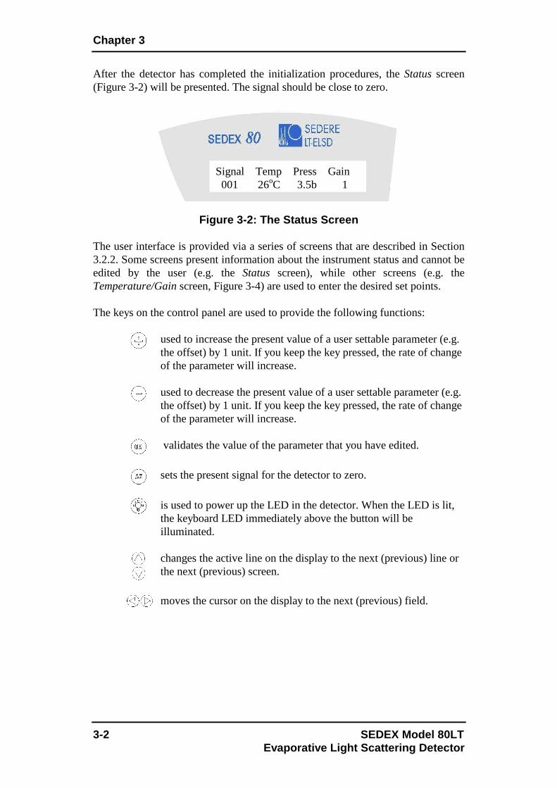
After the detector has completed the initialization procedures, the Status screen (Figure 3-2) will be presented. The signal should be close to zero.
Figure 3-2: The Status Screen The user interface is provided via a series of screens that are described in Section 3.2.2. Some screens present information about the instrument status and cannot be edited by the user (e.g. the Status screen), while other screens (e.g. the Temperature/Gain screen, Figure 3-4) are used to enter the desired set points. The keys on the control panel are used to provide the following functions:
used to increase the present value of a user settable parameter (e.g. the offset) by 1 unit. If you keep the key pressed, the rate of change of the parameter will increase.
used to decrease the present value of a user settable parameter (e.g. the offset) by 1 unit. If you keep the key pressed, the rate of change of the parameter will increase.
validates the value of the parameter that you have edited.
sets the present signal for the detector to zero.
is used to power up the LED in the detector. When the LED is lit, the keyboard LED immediately above the button will be illuminated.
changes the active line on the display to the next (previous) line or the next (previous) screen.
moves the cursor on the display to the next (previous) field.
Signal Temp Press Gain 001 26oC 3.5b 1

Start-up Procedure
SEDEX Model 80LT 3-3 Evaporative Light Scattering Detector
3.2.2 The User Interface
The Status screen (Figure 3-2) is the default screen and is presented after initialization of the detector. In addition, it will be automatically presented again if you have accessed another screen and have not made any keystroke within a few seconds. Each parameter change must be validated with OK or the change will not be applied. 3.2.2.a The Status Screen The Status screen (Figure 3-2) presents the present conditions of the detector. This screen cannot be edited, but the desired offset can be set via the Offset screen (Figure 3-3), the temperature and gain can be set via the Temp/Gain screen (Figure 3-4) and the pressure units can be selected via the Noise Filter/Pressure Unit screen (Figure 3-5). Temperature value blinks if desired temperature is not reached and stable. Pressure value blinks is gas pressure is lower than 3.0bars.
When the button is pressed; the Offset screen (Figure 3-3), which is used to select the desired offset is displayed. 3.2.2.b The Offset Screen
Figure 3-3: The Offset Screen
To increase the offset value, click on the key. If you press the button quickly, the offset will increase by 1; if you press and hold the button, the value will increase at the rate of 20mV/sec.
Once you have set the desired offset, press the button to validate the new value. When the instrument is Autozeroed, the Autozero operation updates the Offset value to set the Signal to 0mV.
Press the button to access the Temp/Gain screen (Figure 3-4).
Signal Offset (mV) 000

Chapter 3
3-4 SEDEX Model 80LT Evaporative Light Scattering Detector
3.2.2.c The Temperature/Gain Screen
Figure 3-4: The Temp/Gain Screen The Temp/Gain screen is used to set the desired Temperature and Gain. When the screen is accessed, the cursor is on the Temp setting. This setting can be changed
with the and buttons and validated by the button. The temperature range is 20 to 100oC.
Note: When the detector is initially powered up or if you change the temperature, the temperature may first overshoot the setpoint slightly and then stabilize at the desired point. This initial overshoot is due to the regulation of the instrument and should not be a concern.
Note: To maintain appropriate temperature control, when the lowest temperature is required, it should be set at least 5oC above ambient. Temperature stabilization typical time is 30 minutes. Please, note that the stabilization time for temperature close to the ambient temperature may be higher.
When you press the button, the Gain field can be edited in the normal manner. The gain range is from 1 to 12, each increment of one unit increases the gain by a factor of 2 (e.g. if you change the gain from 1 to 4, the gain is increased by a factor of 8) and the full range of the gain is 1 to 2048. After you have
validated the desired gain setting, press the button again to display the Autozero Offset screen (Figure 3-4b). 3.2.2.d The Autozero Offset Screen
Figure 3-4b: The Autozero Offset Screen
Temp: 50°C Gain: 1
Output Signal Value After AZ: 000mV

Start-up Procedure
SEDEX Model 80LT 3-5 Evaporative Light Scattering Detector
This screen is used to allow the signal to reach the desired value when performing an autozero (by keyboard or external contact closure). This function can be helpful when the user wishes to have a positive signal value instead of zero, especially with some acquisition systems which have only positive signal acquisition capability.
This setting can be changed with the and buttons and validated by the button.
After you have set the desired autozero offset, press the button to display the Noise Filter/Pressure Unit screen (Figure 3-5). 3.2.2.e The Noise Filter/Pressure Unit Screen
Figure 3-5: The Noise Filter/Pressure Unit Screen The Filter/Pressure Unit screen is used to indicate if digital filtering is desired for the signal data (improves signal-to-noise ratio) and the desired units for the pressure display.
When the screen is presented, the cursor is on the Filter field. By pressing or
keys, you change the filtering strength within the following range: • "NO": no filtering. • 0.5s: 0.5 second moving average filtering. • 1s…10s: 1 to 10 seconds moving average filtering.
Note: For better results, the digital Filter should be used unless the peak(s) of interest are very poorly resolved (e.g. when Rs<1.5). Default value is 1s, corresponding to a peak width of approximately 2 seconds at half-height. User manual section 4.5.5 details Filter optimization.
If you have changed the value, press to validate it before you press the button to access the Press Unit line. The pressure unit line allows for the selection
of KPa, bar or psi for pressure units, the desired selection is made via the or
key, and validated by the key.
When you press the button, the LED screen (Figure 3-6) will be displayed.
Filter: 1s Press Unit: bar

Chapter 3
3-6 SEDEX Model 80LT Evaporative Light Scattering Detector
3.2.2.f The LED Screen
Figure 3-6: LED Screen
The LED screen is used to turn the light source On/Off and is equivalent to the
Light Source button on the control panel. Use the button followed by the
button to turn the LED on and the button followed by the button to turn it off. The # hours field indicates the number of hours that the LED has been in use. The lifetime of the LED is approximately 5000h. When this period has been reached, a message indicating that the maximum usage of the lamp has been exceeded will be presented when the unit is powered up and the orange LED on the keyboard blinks. To reset the field, move the cursor to the Reset Time Elapsed field and validate by pressing on the key.
Note: The Reset Time Elapsed field should be validated with only when you change the lamp.
When you press the button, the Gas Valve screen (Figure 3-7) will be displayed. 3.2.2.g The Gas Valve Screen
Figure 3-7: The Gas Valve Screen The Gas Valve screen is used to open/close the gas valve and to setup a program to close the gas valve after a user selected time period. To use this feature, move the cursor to the time field, indicate the appropriate time, then move the cursor to
Off and use the or key to select On and press .
When you press the button, the External Shutdown screen (Figure 3-8) will be displayed.
LED: ON #H Reset Time Elapsed
Gas Valve: Open Prog Time: 0 min Off

Start-up Procedure
SEDEX Model 80LT 3-7 Evaporative Light Scattering Detector
3.2.2.h The Power Down Screen The Power Down Mode screen (Figure 3-8) is used to indicate which features should be shut down upon receipt of a power down signal from an external source or from the menu.
Figure 3-8: The Power Down Screen The three options provided for external shutdown are summarized in Table 3-1. Mode Photomultiplier Lamp Heating Gas flow General Off Off Off Off Standby Off Off On Off Cleaning Off Off On On
Table 3-1: Power Down Options
To select the desired Power Down mode, use the or key to access the
desired mode and then press to validate the selection.
Note: It will take a few minutes to attain operating status from General power down mode, as the temperature must stabilize.
Once the Power Down mode has been chosen and validated, the detector can be powered down in two ways: • External event cable power down contact closure: The detector will stay in
the selected power down mode while the contact remains closed. It comes back in normal mode when the contact closure is released.
• Power down screen: Press the button to access the power down screen,
then press again the button to place the cursor on the Power down activate
line. Validate with to put the detector in power down mode.
Note: To leave the power down mode, release the contact closure if power down has been activated by external event or press any key if power down has been activated from the Power down screen.
Power down Mode: General Activate?

Chapter 3
3-8 SEDEX Model 80LT Evaporative Light Scattering Detector
When the cursor is on the Power down activate line, pressing the button will present the Total Lifetime Elapsed screen (Figure 3-9). 3.2.2.i The Total Lifetime Elapsed Screen
Figure 3-9: The Total Lifetime Elapsed Screen The Total Lifetime Elapsed information screen indicates the usage of the detector
and cannot be edited by the user. When you press the button, the Serial Number screen (Figure 3-10) will be displayed. 3.2.2.j The Serial Number Screen
Figure 3-10: The Serial Number Screen The Serial Number screen cannot be edited by the user. The last character indicates the detector hardware revision. When you press the button, the Firmware screen (Figure 3-11) will be displayed.
Total Lifetime Elapsed ######## hrs
Serial Number #########

Start-up Procedure
SEDEX Model 80LT 3-9 Evaporative Light Scattering Detector
3.2.2.k The Firmware Screen
Figure 3-11: The Firmware Screen This information screen presents the firmware version and date, where MM is the month, and YY the year. The Firmware screen cannot be edited by the user.
When you press the button, the Factory Menu Code screen (Figure 3-12) will be presented. 3.2.2.l The Factory Menu Code Screen
Figure 3-12: The Factory Menu Code Screen The Factory Menu Code screen is used by the service engineer to access a variety of service features and is not designed to be employed by the user.
Firmware Version: V.v Firmware Date: MM/YY
Factory Menu Code ____ Authorized persons only

Chapter 3
3-10 SEDEX Model 80LT Evaporative Light Scattering Detector
3.3 Initial Test Procedure 3.3.1 Preliminary Activities This section presents a protocol that can be used to ensure that the detector is working in the proper way. A detailed standard operating procedure (I.Q./O.Q./P.Q.) is presented as Appendix 3.
Note: When the instrument is set-up, the procedures indicated below should be performed to determine the specific characteristics of your unit. We suggest that you save the results in a permanent location, as they can be very useful when you are performing troubleshooting activities.
Note: Before starting the tests for a new instrument or after storage, flush the detector with water at a flow of 1mL/min at least 15 minutes.
The following activities should be performed:
a) Power up the instrument. When the detector is shipped from factory, the gain is set to 1 and the offset to 0mV. The Signal screen should indicate 000 (or a very small signal).
b) Access the Temperature/Gain screen, set the temperature to 50oC and
press . View the Status screen and verify that the temperature is rising to the setpoint on the Status screen. Temperature regulation is stable when the Temperature value stops blinking.
Note: When the detector is initially powered up or if you change the temperature, the temperature may first overshoot the setpoint slightly and then stabilize at the desired point. This initial overshoot is due to the regulation of the instrument and should not be a concern.
c) Provide gas to the detector and adjust the pressure to 3.5bar (51psi). If the pressure is less than 3.0bar (44psi), the pressure value blinks, indicating that the detector is not ready.
Note: Make certain that the pressure of gas supplied to the detector is less that 4.5bar (67psi). If the pressure increases above 4.5bar, the pressure sensor may be damaged. This damage is not covered by the warranty.
If you have an external gas gauge, make sure that the external reading and the reading on the Status screen are in good agreement.

Start-up Procedure
SEDEX Model 80LT 3-11 Evaporative Light Scattering Detector
d) Press the button. The signal should be close to zero and remain constant.
e) Set the noise filtering to 1s (Refer to Section 3.2.2.e).
3.3.2 Electronic Noise Test To determine the electronic noise:
a) Do not switch the light source on. Do not switch the HPLC pump on (no solvent flow).
b) Make sure that the siphon is filled and the bulkhead is blocked with ParafilmTM to avoid a Venturi effect.
c) Set gas pressure to 3.5bar and temperature to 50°C. Wait for stable temperature.
d) Set gain 12 and monitor the signal for a period of 5 min. The variation in the signal should be less than +/- 2mV (there may be some spiking of the signal).
e) Record the level and autozero the detector again. 3.3.3 Background Noise (Stray Light) Test To determine the background noise:
a) Do not turn on the HPLC pump (no solvent flow).
b) Make sure that the siphon is filled and the bulkhead is blocked with ParafilmTM to avoid a Venturi effect.
c) Set gas pressure to 3.5bar and temperature to 50°C.
d) Switch on the light source.
e) Change the Gain to 1.
f) Set the offset to 0mV.
g) Set the offset after Autozero to 0mV (Refer to Section 3.2.2.d).
h) Autozero the detector. i) Change the Gain to 12.
j) Wait 15 minutes for stabilization and record the signal level. The expected level is typically 100mV to 150mV. The exact value will vary slightly and small deviations should not be a cause for concern. The values for your unit are provided on the test report supplied with the detector.
Chapter 3
3-12 SEDEX Model 80LT Evaporative Light Scattering Detector
3.3.4 Solvent Noise Test
To determine the solvent noise:
a) Ensure that the gas is flowing at 3.5bar (51psi), the temperature is set to 50oC and stable and the pump is switched off.
b) Switch on the light source and set the gain to 12 and monitor the signal. Do not autozero the detector. The signal may be negative.
c) Bypass the column and connect the detector to the mobile phase delivery system and pump the solvent that you expect to use for your analyses through it at a flow rate of 1mL/min.
d) Monitor the baseline for a few minutes.
• If water is used as the solvent, the signal should be less than 10mV. Higher values could be observed if non-HPLC grade water (with a higher non-volatile residue) is used.
• If an organic solvent is used, the signal should be less than 200mV.
• For mixed aqueous/organic solvents, the expected signal is approximately linear with respect to the concentration of organic phase in the solvent (e.g. a water/organic solvent (50:50) mixture should provide a signal of approximately less than 100mV).
Note: The purity of the solvent is critical for a low background noise. The sensitivity is inversely proportional to the solvent noise.
Note: In most cases, distilled water and HPLC grade solvents are satisfactory. When you are comparing solvents from different sources, the most critical parameter is the Residue After Evaporation; this parameter should be less than 1ppm to maximize the sensitivity of the detector.
If the instrument fails the Solvent Noise test, it is most likely due to an impurity in the solvent rather than a fault with the instrument. If changing the solvent source does not solve the problem, it may be necessary to decontaminate the instrument as described in Section 5.4.2 or clean the nebulizer as described in Section 5.3.5.
When filtering the solvent, verify that it does not extract any contaminant from the filter.
The mobile phase should not contain non-volatile solvent modifiers. Volatile solvent modifiers (e.g. CHOOH, CH3COOH, CF3COOH, NH4 Formate, NH4, Acetate, (C2H5)3N)…) can be used, but they may increase the noise level at high gain settings. In addition, the solvent should not contain preservatives, (e.g. Tetrahydrofuran may contain BHT as a stabilizer).

Start-up Procedure
SEDEX Model 80LT 3-13 Evaporative Light Scattering Detector
3.3.5 Column Noise Test
Note: When strongly retained compounds are slowly eluted from the column, excessive noise will be observed.
To determine the column noise:
a) Turn off the pump and connect the column.
b) Restart the pump and allow the mobile phase to flow through the system. It is suggested that you flush the column with a strong solvent for a few minutes before attaching it to the detector. The flow rate to be used is dependent on to the column ID and is indicated in the following table.
Column ID
(mm) Flow Rate (µL/min)
4.6 1000 2.1 208 1.0 47 0.8 30 0.32 4.8
Table 3-3: Flow Rate versus Column Diameter Indicat ion
c) Set the gain to 12 and monitor the baseline for a few minutes. A
suitable column will provide a baseline that is 20-50mV above the solvent baseline.
Note: If the mobile phase contains acidic modifiers (e.g. CF3COOH), disconnect the detector and wash the HPLC system for 12h before starting to analyze unknown samples. This wash should be performed after the column noise test is completed, but need not be performed after each analysis.

Chapter 3
3-14 SEDEX Model 80LT Evaporative Light Scattering Detector
[This page intentionally left blank]

SEDEX Model 80LT 4-1 Evaporative Light Scattering Detector
4.1 Overview This chapter describes the operations that should be performed on a routine basis when you want to collect chromatographic data using the ELSD 80 Low Temperature Evaporative Light-Scattering Detector. In this discussion, we assume that you have demonstrated that the instrument is operating in an acceptable manner (see Chapter 3) and that the general chromatographic conditions for the separation have been determined. 4.2 Preparing the Detector for Operation To prepare the detector for operation:
a) Power up the detector by pressing the switch on the rear panel.
b) Open the gas distribution valve and set the pressure to 3.5bar (51 Psi). The pressure is indicated on the Status screen.
c) Ensure that the overflow siphon for the nebulization chamber contains
sufficient liquid. If necessary, pump few mL of solvent through the instrument to fill the siphon.
d) Select the desired temperature. The temperature is set on the
Temp/Gain screen, which is accessed by pressing the button two times when the Status screen is displayed.
e) Start the mobile phase flow through the instrument and allow the
overall system to operate for at least 15 minutes to ensure that all components are equilibrated and a stable baseline is obtained.
Note: The Solvent Noise test (Section 3.3.4) and the Column Noise test (Section 3.3.5) should be performed to verify that the detector is functioning in a proper manner.
Note: The liquid level in the siphon must be stable and should be equal at both sides.
4 Operating the Detector

Chapter 4
4-2 SEDEX Model 80LT Evaporative Light Scattering Detector
4.3 Auto-zeroing the Detector 4.3.1 Manual Auto-zeroing of the Detector To auto-zero the detector:
a) Set the Gain to the desired value. The gain is set on the Temp/Gain
screen, which is accessed by pressing the button two times when the Signal screen is displayed.
b) Press the button. The detector will be automatically auto-zeroed at this point.
c) If the signal is to be offset, set the offset at this time. The Offset screen
is accessed by pressing the button when the Status screen is displayed.
Note: The offset must be selected after the detector is auto-zeroed, as the Auto-zero operation sets the signal to 0.
Note: If you change the gain selection, make sure that the detector is auto-zeroed again before taking any measurement.
4.3.2 External Auto-zeroing of the Detector If desired, the auto-zero command can be initiated by an external device such as the HPLC system controller. To employ this feature, a cable from the external device is plugged into the Ext. Autozero socket on the rear panel (Section 2.5.3). To auto-zero the detector, a contact closure signal or a TTL signal is used to short circuit the contacts. The signal should be at least 1 sec long, with a maximum current of 20mA at 5V. If a TTL signal is used please make sure to use the correct polarity identified on the cable.

Operating the System
SEDEX Model 80LT 4-3 Evaporative Light Scattering Detector
4.4 Routine Operation of the Detector In general, operation of an HPLC system with Evaporative Light-Scattering Detection is similar to operation of the system with other detectors. During operation of the detector, the following points should be considered:
a) Make certain that the exhaust from the detector is led into a fume hood or other device and make sure that there is a continuous flow of gas through the detector (i.e. no constriction). If a vacuum is used, ensure that the vacuum effect will not disturb the detector (Section 2.5.2).
b) Ensure that the siphon is filled with liquid at all times. The overflow
from the siphon should be collected in a suitable container.
c) Make sure that all flow connections are properly tight. In case of any leak, switch off the pump immediately and remove the liquid.
d) Never exceed a gas pressure of greater than 4.5bar (67psi).
e) Avoid the use of solvent or compounds that could corrode the detector.
The mobile phase is in contact with Glass and Teflon tubing and the evaporation tube is made of Stainless Steel.
4.5 Optimizing Performance 4.5.1 Selecting the Optimum Temperature
There are two factors that should be taken into account when selecting the optimum temperature for the detector: • Increasing temperature will optimize the evaporation of the mobile
phase. • Decreasing temperature will minimize the decomposition of thermally
labile compounds and the volatilization of semi-volatile compounds.
The exhaust gas should not be allowed to enter the laboratory to avoid any injury or laboratory pollution.
Leakage of hazardous solvents may cause personal injury or laboratory pollution.

Chapter 4
4-4 SEDEX Model 80LT Evaporative Light Scattering Detector
A very reasonable start is to set the temperature to 60oC if an aqueous mobile phase is used and 40oC if an organic mobile phase is used (these temperatures are suggested for a flow rate of 1mL/min). At higher flow rates, more elevated temperatures may be required to minimize the noise.
Note: If the mobile phase used is not easily volatile, such as DMSO or DMF, temperature should be increased to allow correct evaporation process.
The temperature can be readily adjusted during the method optimization process. If you suspect that the compound of interest is thermally labile or semi-volatile, a lower temperature could be used to improve the sensitivity by reducing the thermal decomposition or evaporation. For a given flow rate and solvent, there is, however, a point at which the noise in the chromatogram is dramatically increased because not all of the mobile phase is vaporized. As an example, consider the analysis of caffeine with evaporation temperatures of 30oC and 60oC (Figure 4-1) [the conditions for the separation are - Column: ODS KromasilTM (5µm, 30 x 2.1mm), Sample: 4µL (10mg/L) Caffeine]. Eluent: Water, 0.2mL/min, temperature as indicated). It is clear that the use of a low temperature provides significantly better sensitivity for volatile and thermally sensitive compounds.
Figure 4-1: Chromatogram of Caffeine at Various Tem peratures
The minimum temperature that can be used is dependent on the flow rate and the nature of the mobile phase.

Operating the System
SEDEX Model 80LT 4-5 Evaporative Light Scattering Detector
4.5.2 Optimizing the Mobile Phase Particulate matter in the mobile phase will increase the background noise. The purity of the solvent is a critical issue in the noise. When filtering the solvent, verify that it does not extract any contaminant from the filter.
As an example, consider the analysis of a sample in a pure water mobile phase and a polluted water mobile phase. It is clear that the use of an insufficient quality solvent can dramatically decrease your S/N ratio (Sensitivity).
Figure 4-2: Chromatogram with Various Solvent Quali ty The mobile phase should not contain non-volatile solvent modifiers. Volatile solvent modifiers (e.g. CHOOH, CH3COOH, CF3COOH, NH4 Formate, NH4. Acetate, (C2H5)3N)…) can be used, but they may increase the noise level at high gain settings. In addition, the solvent should not contain preservatives, (e.g. Tetrahydrofuran may contain BHT as a stabilizer). The wetted parts of the detector are made from Teflon, Stainless Steel, and Glass. Make sure that the solvents do not react with these materials.
Note: Depending on the mobile phase nature and flow rate, the suggested gas pressure 3.5bar (51psi) may have to be adjusted in order to optimize the background noise and so Signal-to-Noise ratio.
The purity of the solvent is critical for a low background noise. The sensitivity is inversely proportional to the solvent noise.
In most cases, distilled water and HPLC grade solvents are satisfactory. When you are comparing solvents, the most critical parameter is the Residue After Evaporation; this parameter should be less than 1ppm to maximize the sensitivity of the detector.
Chapter 4
4-6 SEDEX Model 80LT Evaporative Light Scattering Detector
4.5.3 Sample Pretreatment If the sample contains any particulate matter, it should be filtered through a 0.2µm or 0.45µm filter before injection. 4.5.4 Column Treatment The chromatographic column typically contains microparticles which are used to separate the compounds of interest. Under certain conditions, the column packing will undergo chemical and/or mechanical breakdown, this may lead to the introduction of particulate matter in the detector, which may lead to an increase in the noise.
Note: When strongly retained compounds are slowly eluted from the column, excessive noise will be observed.
The breakdown of the column packing is dependent on a variety of factors including the particle size, type of column packing, the manufacturer of the column and the nature of the mobile phase (high pH may degrade silica based columns).
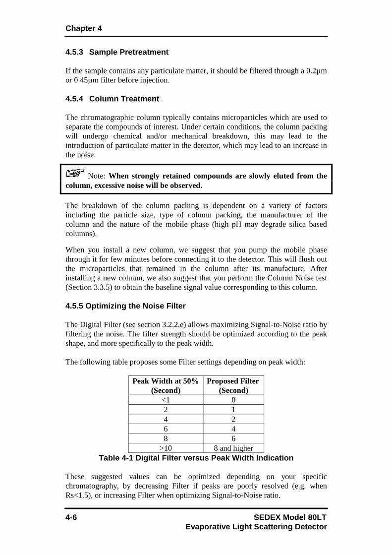
When you install a new column, we suggest that you pump the mobile phase through it for few minutes before connecting it to the detector. This will flush out the microparticles that remained in the column after its manufacture. After installing a new column, we also suggest that you perform the Column Noise test (Section 3.3.5) to obtain the baseline signal value corresponding to this column. 4.5.5 Optimizing the Noise Filter The Digital Filter (see section 3.2.2.e) allows maximizing Signal-to-Noise ratio by filtering the noise. The filter strength should be optimized according to the peak shape, and more specifically to the peak width. The following table proposes some Filter settings depending on peak width:
Peak Width at 50% (Second)
Proposed Filter (Second)
<1 0 2 1 4 2 6 4 8 6
>10 8 and higher Table 4-1 Digital Filter versus Peak Width Indicati on
These suggested values can be optimized depending on your specific chromatography, by decreasing Filter if peaks are poorly resolved (e.g. when Rs<1.5), or increasing Filter when optimizing Signal-to-Noise ratio.

Operating the System
SEDEX Model 80LT 4-7 Evaporative Light Scattering Detector
Example: Comparison of digital filters using the SOP test (injection of 5ppm caffeine at gain 12). Peak width at half-height is 2.5S.
Filter 0s Filter 1s Filter 2s Signal Height 124 mV 122mV 110mV Noise (ASTM) 3.2mV 1.1mV 0.7mV Peak Width (at 50% height)
2.5 second 2.5 second 2.8 second
S/N 37 110 157 Table 4-2 Sensitivity improvement depending on Filt er
Signal-to-Noise ratio is multiplied by 3 when selecting Filter 1s without any peak broadening effect. If Signal-to-Noise ratio is more important than resolution, a Filter 2s or higher can be set to improve sensitivity even better. 4.6 Powering Down and Shutting Down the Detector If desired, some or all functions of the instrument can be powered down at the end of an automated series of analyses. These power down features are described in detail in Section 3.2.2.h. To shut down the instrument:
a) Turn off the pump. b) Allow the nebulization gas to flow through the detector for few
minutes (30min is recommended) to drain the evaporation tube and detection chamber.
c) Turn off the power to the detector (if desired).
If ELSD is used as a second detector and is not being used for some time, it is recommended to remove it from the liquid chromatography flow path in order to avoid any clogging of the nebulizer or deposition of substances inside the detector. Closing gas valve while the pump is still running may result in serious nebulizer damage.
If you are using a mobile phase which contains salts, acids or bases, pump few mL of water or methanol through the system before switching off the detector to prevent any deposition of substances and possible corrosion of the instrument.

Chapter 4
4-8 SEDEX Model 80LT Evaporative Light Scattering Detector
[This page intentionally left blank]

SEDEX Model 80LT 5-1 Evaporative Light Scattering Detector
5.1 Overview This chapter describes:
• The maintenance procedures that should be performed by the operator on a routine basis (Section 5.2).
• Troubleshooting activities that should be useful in determining the cause of erratic or erroneous results (Section 5.3).
• Cleaning and decontamination procedure that should be performed to maintain instrument performance (Section 5.4).
• Light source exchange (Section 5.5) 5.2 Maintenance The ELSD 80 Low Temperature Evaporative Light-Scattering detector is designed to require a minimum of maintenance activities. If preventive maintenance activities are followed, the detector should provide high sensitivity measurements without intervention by the operator. The following general recommendations are proposed:
• Maintain the detector in a clean laboratory environment. • If the instrument is not going to be used for a period of time, flush out
any mobile phase that contains acids, bases or salts to prevent the deposition of foreign matter on components or corrosion of the instrument.
• Only use clean gas (particle-free and oil residue-free).
5 Maintenance and Troubleshooting
Closing gas valve while the pump is still running may result in serious nebulizer damage. If ELSD is used as a second detector and is not being used for some time, it is recommended to remove it from the liquid chromatography flow path in order to avoid any clogging of the nebulizer or deposition of substances inside the detector.

Chapter 5
5-2 SEDEX Model 80LT Evaporative Light Scattering Detector
For an efficient Preventive Maintenance: After each session and before shutting down the HPLC system, the ELSD should be cleaned in order to ensure good performances. Preventive maintenance consists in cleaning the detector before shutting down after the last analyses:
a) Let the mobile phase or solvent flow to flush particles which could remain in the detector.
b) Eventually increase temperature in order to dissolve possible deposit. c) Stop the mobile phase flowing but let the gas flow at least 30min to dry
to avoid particles deposit. d) Stop the gas flow. e) Shut down the detector.
The time required for each step depends on the application, solvents, type and concentration of the samples and should be determined accordingly.
Note: It is not necessary to access inside the instrument in routine operation. If the suggestions provided in this chapter do not remedy the problem, contact your local distributor.
Note: The L.E.D. used as the Light Source has a long but finite lifetime (~ 5000 hours) and should be replaced periodically by a skilled technician. When this period has been reached, a message indicating that the maximum usage of the lamp has been exceeded will be presented when the unit is powered up and the orange L.E.D. on keyboard will blink.

Maintenance and Troubleshooting
SEDEX Model 80LT 5-3 Evaporative Light Scattering Detector
5.3 Troubleshooting 5.3.1 General Troubleshooting Information The SEDEX Model 80 Low Temperature Evaporative Light-Scattering Detector is designed to be incorporated into a Liquid Chromatography system. It is important to note that the detector response reflects the overall performance of the system, and a “problem” that is seen on the detector output may not necessarily be a “detector problem”. In almost all cases, there is one and only one cause for a problem. As an example of this point, if the user observes a noisy baseline, it is possible that the problem is due to:
• The pump (e.g. a defective check valve). • The mobile phase (e.g. improper degassing or high residue after
evaporation). • The column (e.g. elution of strongly retained components).
• The nebulizer (e.g. lack of maintenance) • The detector (e.g. an electronic problem).
It is very unlikely that two problems occur at the same time. The role of the troubleshooting activities is to determine the cause of the problem. In the following, we assume that the operator has already determined that other components of the system are operating in an appropriate way.
Note: The control panel and instrument electronics do not contain any replaceable components. If the suggestions provided in this chapter do not remedy the problem, contact your local distributor.
If the digital display does not illuminate when the detector is powered up, turn the unit off and inspect the main fuses. If necessary, replace the fuses with some of the same rating as the original ones for all 115V and 230V units. The fuses are located inside the main power module on the rear panel (Figure 2-2). A set of replacement fuses is delivered in the starting kit. If the fuses are not blown or if the replacement fuses blow up again, contact your local distributor.
Do not disassemble the nebulizer. Disassembling the nebulizer will destroy it and this will void the warranty.

Chapter 5
5-4 SEDEX Model 80LT Evaporative Light Scattering Detector
5.3.2 Initial Troubleshooting Activities
a) Make sure that the instrument and all components of the detector are grounded to a true ground.
b) Check to ensure that the liquid level in the siphon is appropriate, and
there is no liquid pooling close to the evaporation tube inlet.
c) Check that the gas pressure is sufficient and stable. The selected pressure for most applications is 3.5bar (51psi) and gas consumption is 3L/min for HPLC nebulizer and 4L/min for the CC nebulizer. Pressure above 4.5bar (67psi) can damage the pressure sensor. The gas filter should be clean and in place. Only use gas free of oil residue.
d) Ensure that the flow rate of the pump is constant and check that there
are no leaks in the chromatography system. 5.3.3 Perform the Noise Tests Repeat the tests described in Section 3.3 and compare the observed data to the results that were obtained when the unit was initially installed. These tests can be very valuable to isolate the problem. As an example of this point, if the Electronic Noise test (Section 3.3.2), Background Noise test (Section 3.3.3) and Solvent Noise test (Section 3.3.4) provide results that are similar to that obtained when the unit was initially installed, but the Column Noise test (Section 3.3.5) provides a significantly different value than what was obtained at installation, it is likely that the problem is in the column (e.g. highly retained compounds are being eluted). 5.3.4 Specific Detector Troubleshooting
a) The mist from the nebulizer should be homogeneous. If it is not homogeneous, the nebulizer, the needle or the Teflon tube may be partially obstructed. To remove the obstruction, pump a solvent that can dissolve the foreign material. As an alternative, the nebulizer can be placed in an ultrasonic bath to dissolve the foreign material. Instructions about cleaning of the nebulizer are presented in Section 5.3.5.
Do not disassemble the nebulizer. Disassembling the nebulizer will destroy it and this will void the warranty.

Maintenance and Troubleshooting
SEDEX Model 80LT 5-5 Evaporative Light Scattering Detector
b) If the sensitivity of the detector is low, ensure that there are no leaks in the system. Make sure you are using a fresh sample and consider running the test using a backpressure loop instead of a column. Alternatively, the L.E.D. may need to be replaced or the nebulizer could be obstructed. If the noise test did not show that the problem could be caused by the application or the system, a decrease in the sensitivity is often caused by the nebulizer (main cause). Clean the nebulizer as described in Section 5.3.5. If the sensitivity does not return to normal, the nebulizer might need to be replaced. Please note that the root cause might also be in different module, i.e volumes injected by the autosampler might be too low or dead volumes in capillary connections may cause peak broadening.
c) If the detector signal is saturated or if there is a decrease in the dynamic range of the system, it is possible that a residue is passing through the detector cell: this will lead to an intense signal due to a significant amount of light-scattering. This residue may be a result of the elution of strongly retained materials from the column, or may come from the solvent. To determine the cause of the problem, bypass the column and observe the signal intensity:
• If the signal returns to normal, strongly retained materials are
eluting from the column. Flush the column with a strong solvent to elute all material.
• If the signal does not return to normal, the solvent contains a
too high residue material, after evaporation and is not suitable for use with the detector.
d) If the noise of the detector without solvent is high or if ghost peaks
occur, it is possible that foreign material is present in the drift tube. In this situation, increase the temperature to 100oC and pump solvent at the rate of 2mL/min, using a gas pressure of 3.5 bar (51 psi).

Chapter 5
5-6 SEDEX Model 80LT Evaporative Light Scattering Detector
5.3.5 Nebulizer Cleaning and Replacement Procedures If the mist of the nebulizer is not homogeneous, the nebulizer, the needle or the Teflon tube may be obstructed. To remove the obstruction, pump a solvent that can dissolve the foreign material. As an alternative, the nebulizer can be placed in an ultrasonic bath to dissolve the foreign material.
In case of the nebulizer doesn’t produce a spray and the liquid drawn directly to the siphon even if the pressure display is 3.5bars, make sure you are using the correct black gas tube orientation fitting for the nebulizer, where the white one-way valve is at the lower end (near the gas arrival) on the front panel. The installed Nebulizer/Glass Chamber assembly is shown in Figure 2-5. To remove the nebulizer from the instrument:
a) Switch off the pump and the ELSD detector.
b) Remove the black front panel cover. Pull its left side.
c) Disconnect the nebulizer liquid inlet from the
column and, Disconnect the gas inlet from the nebulizer by pushing on the white inlet (refer to Figure 2-4 for detail).
d) Remove the nebulizer from the glass cell by unscrewing the black plastic nut with the right hand whilst maintaining the nebulizer with the left hand. Take care not to pull or twist the nebulizer capillary. The black nut which maintains the nebulizer on the glass cell and its seal should be removed from the nebulizer.
Handle the nebulizer carefully and do not disassemble the rear part of the nebulizer, which is protected by the colored thermal seal. Improper handling of the nebulizer will destroy it and this will void the warranty. The nebulizer rear part is a strategic setting which mustn't be dismounted for any reason. In case the user has removed it, the only solution is to perform a nebulizer replacement. If the nebulizer cannot be repaired by cleaning by pumping solvent through it or with an ultrasonic bath, it requires a replacement.

Maintenance and Troubleshooting
SEDEX Model 80LT 5-7 Evaporative Light Scattering Detector
e) Remove the gas inlet quick fitting and the black plastic nut to avoid
damaging the seals with the cleaning solvent.
To clean the nebulizer:
a) Fill an ultrasonic bath with water. Fill a beaker (50 or 100mL) with approximately 2cm of an appropriate solvent. The solvent is dependent on the nature of the material that is present in the nebulizer. In most cases, ethanol is a satisfactory solvent.
b) Place the nebulizer vertically in the beaker 2cm solvent bath. The
nebulizer outlet should be placed at the bottom of the bath and the nebulizer inlet liquid tubing should be pointing up. Take care to ensure that the rear part of the nebulizer is not in contact with the solvent.
c) Clean the nebulizer for approximately 30 minutes with the solvent, and then replace the solvent with water and clean for an additional 30 minutes.
2cm

Chapter 5
5-8 SEDEX Model 80LT Evaporative Light Scattering Detector
To re-install the nebulizer or replace it by a new one or another nebulizer model
a) For re-installing the nebulizer after a nebulizer cleaning, re-install the gas inlet quick fitting and the black plastic nut with its seal.
b) Reverse the order of previous steps (nebulizer removing). In case the black gas tubing has been removed, make sure you are using the correct orientation, where the white one-way valve is at the lower end (near the gas arrival).
c) Make sure there is no liquid or gas leak at all connections and check
for possible leakage that could affect the detector performance or create laboratory pollution when you turn on the pump.
d) Install the black front panel cover, first fix its right side, and then push
its left side.
e) Test the nebulizer to ensure that it is working properly.
Note: If the Nebulizer cleaning procedure does not solve the problem, contact your local distributor for a nebulizer replacement.
In case the black gas tubing has been removed, make sure you are using the correct orientation, where the white one-way valve is at the lower end (near the gas arrival). Avoid leaks at all connections and check for possible leakage when you turn the pump on again.
Union Column Bulkhead
Nut Glass chamber
Siphon Overflow
Nut
Nebulizer
Gas inlet Fitting
Gas one-way Valve

Maintenance and Troubleshooting
SEDEX Model 80LT 5-9 Evaporative Light Scattering Detector
5.3.6 Gas Flow Problems The gas flow is indicated on the Status screen and is controlled by a valve inside the detector housing. If the gas flow is stopped and the menu command does not work, it may be possible to perform a manual bypass. To bypass the internal gas valve:
a) Disconnect the detector from the mains. b) Remove the cover from the detector. c) Turn the red button on the gas flow valve on the rear panel to bypass
the valve (Figure 5-1). d) Replace the cover and power up the instrument.
Figure 5-1: Gas Flow bypass Valve
5.4 Cleaning and Decontamination 5.4.1 Instrument Cleaning
1. Switch the instrument off.
2. Disconnect all connection cable (power cable, signal cable, autozero cable, RS-232 cable if any, instrument gas input and nebulizer tubing).
3. Allow the detector to cool down.
4. Clean the outside of the detector with a non-abrasive cloth. If
necessary, a liquid such as soapy water or ethanol can be used to remove stains or foreign material.
Manual Bypass Switch On Gas Valve

Chapter 5
5-10 SEDEX Model 80LT Evaporative Light Scattering Detector
5.4.2 Instrument Decontamination
a) Set the evaporation temperature to 100oC and the gas pressure to 3.5bar (51psi).
Pump the appropriate solvent through the system at the rate of 1mL/min. The solvent will be determined by the nature of the samples that were previously analyzed by the detector. If you do not know the nature of the sample, ethanol is a good choice. Do not use solvents that can potentially corrode the instrument. Maintain the flow and temperature during 3 hours at least.
b) Clean the outside of the detector with a non-abrasive cloth. If necessary, a liquid such as soapy water or ethanol can be used to remove stains or foreign material.
5.5 Light source exchange The L.E.D. used as Light Source has a long but finite lifetime (~ 5000 hours) and should be replaced periodically. A decreasing L.E.D. light intensity will cause decreasing signal heights over time. When this period of 5000 hours has been reached, a message indicating that the maximum usage of the lamp has been exceeded will be displayed when the unit is powered up and the orange L.E.D. on keyboard will blink. The Light Source exchange part number is: ● 80007 for Sedex 80 Hardware from A to C ● 80023 for Sedex 80 Hardware from D Hardware revision can be checked as the last letter of the detector Serial Number (refer to 3.2.2.k).
Figure 5-3: The Light Source

Maintenance and Troubleshooting
SEDEX Model 80LT 5-11 Evaporative Light Scattering Detector
a) Switch the detector on and switch off the lamp by pressing the button. b) Switch the detector off and remove the detector cover. c) Disconnect the light source connector
(step 1) and unscrew the light source cap (step 2). Note: For reinstallation, the white connector cannot be placed in the wrong way (mechanical protection).
d) Screw the new light source cap. Do not
plug in the light source connector now.
e) Switch on the detector and switch on the lamp by pressing the button. Do not plug in the light source connector now.
f) Check the voltage at VLED test point on ALIM004v2 Board
(Figure 5-4). Do not plug in the light source connector now. The ground should be one of the fixing screws that attach the board to the detector.
Figure 5-4: The ALIM004V2 Board Lamp Setting
g) The voltage at VLED must be set to the value that is provided with the
new L.E.D. with a precision of 2 digits (example: + 3.40V). If the voltage is incorrect, adjust with trimmer POT1. Do not plug in the light source connector now.
h) Switch off the light source by pressing the button and plug in the white light source connector.
i) Switch on the light source by pressing the button.
1 2
VLED
Trimmer POT1
Chapter 5
5-12 SEDEX Model 80LT Evaporative Light Scattering Detector
j) Wait for 5 minutes and check the VLED voltage. If necessary, adjust the voltage with trimmer POT1.
Note: If the potential is not set accurately, the lifetime of the L.E.D. will be adversely affected.
k) In the LED menu (Section 3.2.2.f), access the "Reset time elapsed" line, and press OK to reset the elapsed time counter for the L.E.D.

SEDEX Model 80LT A1-1 Evaporative Light Scattering Detector
Detection High Sensitivity Photomultiplier Light Source Selected High Efficiency Blue L.E.D. Temperature Range Ambient to 100oC Gas Flow Control Manual and computer controlled (power down)
nebulization gas flow and patented auxiliary gas flow Gas Consumption Less than 3L/min for HPLC Nebulizer, less than
4L/min for CC Nebulizer and less than 5L/min for Flash Chromatography Nebulizer
Eluent Flow Rate HPLC Nebulizer: 100µL/min to 2.5mL/min. CC Nebulizer: 1 to 4mL/min. Flash Chromatography Nebulizer: 100µL/min to
5mL/min. Instrument Control Microprocessor with stand alone manual keypad or
Windows based PC control (Windows 9x, NT, 2000 or XP) for Models with RS-232 activated
Operating Parameters Liquid Crystal Digital Panel Control Software/Driver (option) Full Windows Compatibility (Windows 9x, NT, 2000
or XP). Universal interface with full control of ELSD parameters and data collecting
Signal Drift Less than 2mV/30min Signal Output 0-1V (Analog) RS-232 (Digital) when activated Inputs Remote Autozero (Contact Closure and TTL) Remote Powerdown Mode (Contact Closure and TTL) Power Down Mode General Standby Cleaning Zero Control Manual Auto Zero and Remote Auto Zero
Appendix 1: Specifications
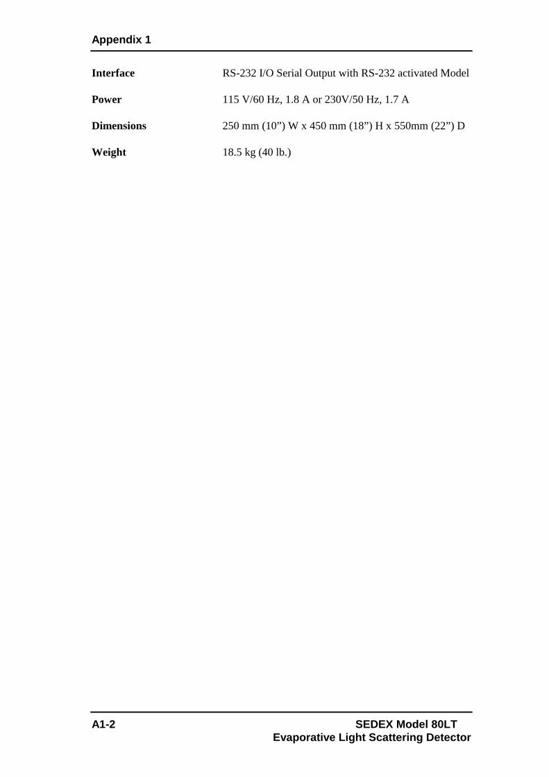
Appendix 1
A1-2 SEDEX Model 80LT Evaporative Light Scattering Detector
Interface RS-232 I/O Serial Output with RS-232 activated Model Power 115 V/60 Hz, 1.8 A or 230V/50 Hz, 1.7 A Dimensions 250 mm (10”) W x 450 mm (18”) H x 550mm (22”) D Weight 18.5 kg (40 lb.)

SEDEX Model 80LT A2-1 Evaporative Light Scattering Detector
Part Part Number
Nebulizer [1] see below Glass Nebulization Chamber [2] 85009-10 Light Source (L.E.D.) Hardware revision can be checked as the last letter of the detector serial number (refer to 3.2.2.k) For SEDEX 80LT Hardware A to C 80007 For SEDEX 80LT from Hardware D 80023 Black Plastic Nut for Nebulization Chamber (13 mm Diameter) [3] 45700-13 Black Plastic Nut for Nebulization Chamber (30 mm Diameter) [9] 45700-22 Gas Regulator with Filter and Manometer 45100 Pneumatic tube (diameter 4 mm) for Nebulizer 85016 (includes stainless steel fitting) [6] Drain Assembly (includes fitting P.N. 45108) [4] 45200 Drain Assembly Fitting [5] 45108 Tube Fitting (6 mm diameter) for Gas Regulator 45018 Wall Mounting Fitting (4 mm diameter) [7] 55014 Bulkhead Fitting [8] 85002 Peek Nut 1/16” with Ferrule [10] 85010 Cartridge for Gas Regulator 45007 Power Cable 45600 Autozero Cable 55500 Signal Cable 55400 RS 232 Cable 75092 External Event Cable 754006 Main Power Fuse 45300-3.15T
Nebulizer Flow Rate Range Identifying
Marks Part Number
HPLC Nebulizer 100µL/min - 2.5mL/min Black Seal
2 Rings White Capillary
80003
Combinatorial Chemistry Nebulizer
1.0mL/min - 4.0mL/min Red Seal
1 Ring White Capillary
80008
Flash Chromatography
Nebulizer
100µL/min – 5mL/min
Black Seal No Ring
White Capillary
80005
Appendix 2: Spare Parts List

Appendix 2
A2-2 SEDEX Model 80LT Evaporative Light Scattering Detector
Figure A2-1: Identification of Spare Parts
5
4
7
3
1 2 9 10
6
8

SEDEX Model 80LT A3-1 Evaporative Light Scattering Detector
A3.1 Overview The Standard Operating Procedure (SOP) is provided to perform the Installation Qualification (I.Q.), Operational Qualification (O.Q.) and Performance Qualification (P.Q.) to validate the instrument at your site. The original test report is shipped with each instrument to certify that the instrument passed the final test. Installation of the unit is described in Chapter 2. An Installation Qualification checklist is presented in Section A3-2. The procedure for the Operational Qualification is described on the worksheet presented in Section A3.3. The procedure for the Performance Qualification is described on the worksheet presented in Section A3.4. The overall Detector Performance report is presented in Section A3.5.
Note: The present document should be filled with blue ink, except customer authorization for black ink.
Note: Before starting S.O.P for new instruments or after storage, the following operations must be performed: - Set gas pressure to 3.5bars. - Set the temperature to 50°C and wait for stabilization. - Flush detector with 1mL/min of water at least 15 minutes. Issue 1 : March 2007 Performed by S. Bertoli approved by Ph. Raynaud Issue 2 : December 2007 Performed by S. Bertoli approved by Ph. Raynaud Issue 3 : February 2008 Performed by S. Bertoli approved by Ph. Raynaud Issue 4 : February 2011 Performed by A. Ignasiak approved by E. Verette
Appendix 3: Standard Operating Procedure and I.Q./O.Q./P.Q.

Appendix 3
A3-2 SEDEX Model 80LT Evaporative Light Scattering Detector
A3.2 The Installation Qualification (I.Q.) Checklis t Model Number: ELSD 80LT Instrument Serial Number: ____________________ Location of the Detector: _____________________________________________ a) Has the instrument been delivered as ordered (e.g. according
to the U.R.S. or purchase order)? YES [ ] NO [ ]
b) Has the instrument been checked and verified as undamaged? YES [ ] NO [ ]
c) Has the required documentation been supplied? Is it of correct issue and appropriately identified by Model Number, Serial Number and Date? YES [ ] NO [ ]
d) Have details of all services and utilities required to operate the instrument
been provided? YES [ ] NO [ ] e) Have methods and instructions for user maintenance been provided along with
contact points for service and spare parts? YES [ ] NO [ ] f) Is the selected environment suitable for the instrument (i.e. is adequate room
provided for installation, operation and servicing)? Have appropriate solvent services and utilities (electricity, nitrogen gas, ventilation, solvent waste recovery, etc.) been provided? YES [ ] NO [ ]
g) Has health, safety and environmental information relating to the operation of
this instrument been provided? YES [ ] NO [ ] The manufacturer's procedure for the proper Installation Qualification of this instrument was completed by the following certified person: Name ________________________________________ Title/Affiliation ________________________________ Date ________________ Signature _____________________________________

Standard Operating Procedure and I.Q./O.Q./P.Q.
SEDEX Model 80LT A3-3 Evaporative Light Scattering Detector
A3.3 Operational Qualification (O.Q) Protocol This procedure checks the proper operation of the detector with respect to stability of the electronic boards, the energy of the light source and the sensitivity of the photomultiplier tube (PMT). Model Number: ELSD 80LT Instrument Serial Number: ____________________ Location of the Detector: _____________________________________________
Note: This procedure is designed to certify the initial conditions of the ELSD and requires the original test report. This report is located in the Operator’s Manual immediately after this section (and before the reference chromatograms).
a) Turn on the detector b) Seal the solvent inlet connection (1/16” male fitting) with a plug connection or
a piece of ParafilmTM and fill the glass siphon with water. c) Apply air or nitrogen pressure of 3.5 bar (51 psi), monitored by a regulator and
checked with a pressure gauge.
The display should read 3.5bar +/- 0.1 bar (51 psi)
PRESSURE VALUE _______ PASS [ ] FAIL [ ]
d) Set the temperature to 50°C and wait until the temperature stabilizes (30 minutes).
The display should read 50 °C +/- 1 °C.
SETTING TEMPERATURE _______ PASS [ ] FAIL [ ] DISPLAY TEMPERATURE _______
e) Set FILTER "1s" in the Noise Filter/Pressure Unit Screen. (Refer to Section
3.2.2.e). f) Set the gain to 12. g) Measure the noise over ten 1 min segments. For each segment, measure the
difference between the lowest noise peak and the highest noise peak.

Appendix 3
A3-4 SEDEX Model 80LT Evaporative Light Scattering Detector
Segment + Dev. - Dev. Difference. Segment + Dev. - Dev. Difference. 1 6 2 7 3 8 4 9 5 10
Minimum Value: _______ Maximum Value: ________ Mean Value: ________ The mean noise value should be less than 2mV. PASS [ ] FAIL [ ]. h) Set the Gain to 1 and set the temperature to 50°C (wait until the temperature
stabilizes), allow nitrogen to flow through the instrument at a pressure of 3.5bar (51 psi), set "Offset After Autozero" to zero if needed as described in section 3.2.2.d. and autozero the detector. Raise the Gain to 12, monitor the signal for 5 seconds and enter the value below. Observed Value ________mV Reference Value ________mV (see Test Report) The observed stray light readings should be in the range of 100 – 150mV.
PASS [ ] FAIL [ ] i) This test is performed in the same conditions as for the mean noise value
determination. Position the recorder near 10mV by adjusting the offset and allow the recorder collecting data for 30 minutes. Initial Signal Level ____mV Final Signal Level ____mV 30Min Drift ___mV The baseline drift should be less than 2.0mV. PASS [ ] FAIL [ ]
Note: If any part of the diagnostics fails, please refer to your local distributor for service.
The manufacturer's procedure for the proper Operational Qualification of this instrument was completed by the following certified person: Name ________________________________________ Title/Affiliation ________________________________ Date ________________ Signature _____________________________________

Standard Operating Procedure and I.Q./O.Q./P.Q.
SEDEX Model 80LT A3-5 Evaporative Light Scattering Detector
A3.4 The Performance Qualification (P.Q) Protocol Model Number: ELSD 80LT Instrument Serial Number: ____________________ Location of the Detector: _____________________________________________
Note: Before this procedure is performed, it is necessary to complete the Installation Qualification (Part I) and the Operational Qualification (Part II). The test report presented below or your own appropriate reference test should be used.
1) Turn on the detector and set the conditions as follows:
Temperature : 40oC Gain : 12 Noise filtering : 1s Gas pressure : 3.5bar (51psi) air or nitrogen Siphon : Filled with water Inlet tube (*) : Connected to column (4.6mm I.D. x 30mm) C18, 5µm or 1/16’’ tubing, 0.005’’ I.D. x 200cm Solute : Caffeine as specified on the test report. Flow rate : 1mL/min Mobile phase : 100% HPLC water (*) Remove the plug connector (or ParafilmTM) from the solvent inlet connector before connecting the siphon to the column. Note that when using a loop, it must be placed between the pump and the autosampler.
2) Autozero the detector.
3) Make three (3) 20µL injections of 5ppm caffeine standard (for a full 20µL loop injection, deliver 100µL of the standard each time to ensure that the loop is filled with the standard). The average peak height (mV) should be:
- At least 50mV* under test report conditions (column test). - At least 70mV* under test report conditions (loop test) * For CC version, please deduct 20mV from the above values * For FLASH version, please deduct 45mV from the above values
- Nebulizer type (see certificate): HPLC [ ] CC [ ] FLASH [ ] - Inlet connection type: COLUMN [ ] LOOP [ ]
Peak height 1 _______ mV Peak height 2 _______ mV Peak height 3 _______ mV Average Peak height ______ mV
PASS [ ] FAIL [ ]

Appendix 3
A3-6 SEDEX Model 80LT Evaporative Light Scattering Detector
4) Set gain 6 then autozero the detector.
5) Make six (6) 20µL injections of a 250ppm caffeine standard at gain 6. The
repeatability should be:
3.0% RSD maximum. Peak Area 1: ___________ Peak Area 2: ___________ Peak Area 3: ___________ Peak Area 4: ___________ Peak Area 5: ___________ Peak Area 6: ___________ Avg. Peak Area: __________ Round Standard Deviation (RSD): ________ % Round Standard Deviation (RSD): ______%
PASS [ ] FAIL [ ]
The manufacturer's procedure for the proper Performance Qualification of this instrument was completed by the following certified person:
Name ________________________________________ Title/Affiliation ________________________________ Date ________________ Signature _____________________________________

Standard Operating Procedure and I.Q./O.Q./P.Q.
SEDEX Model 80LT A3-7 Evaporative Light Scattering Detector
A3.5 Overall Detector Performance After the Installation Qualification (I.Q.), Operational Qualification (O.Q.) and Performance Qualification (P.Q.) procedures have been completed, the Overall Detector Performance document should be completed to verify the completion of all tests. Model Number: ELSD 80LT Instrument Serial Number: ____________________ Location of the Detector: _____________________________________________ Part I - Installation Qualification (I.Q.) Date ________ PASS [ ] FAIL [ ] Part II - Operational Qualification (O.Q.) Date ________ PASS [ ] FAIL [ ] Part III - Performance Qualification (P.Q.) Date ________ PASS [ ] FAIL [ ] The above instrument was certified by the following certified manufacturer’s representative: Name ________________________________________________________ Title/Affiliation ________________________________________________ Date ________________ Signature _____________________________________________________ The above instrument was certified within presence of the following customer’s representative: Customer name ________________________________________________ Customer title/Affiliation ________________________________________ Customer Signature _____________________________________________

Appendix 3
A3-8 SEDEX Model 80LT Evaporative Light Scattering Detector
[This page intentionally left blank]

SEDEX Model 80LT A4-1 Evaporative Light Scattering Detector
What follow represent several typical applications that can been performed with ELSD 80 Low Temperature Evaporative Light-Scattering Detector. To obtain more details about an application, please contact your local distributor.
Page Application Chemical Family Application number
A4-3
Fructose Glucose Lactose Sucrose Raffinose Stachyose
Carbohydrates 75
A4-3 Maltodextrins DP1 to DP17 Polysaccharides 35
A4-4 Alkyl Glucosinolates Carbohydrates Derivatives 73
A4-4 Vitamins A, D2, E1, K1 β-carotene Fatty acids 18:3, 18:2, 16,0, 18:0
Vitamins 101
A4-5 Ginseng Extract Saponins Saponins 60
A4-5
Cerebroside Hydroxylated Cerebroside Phosphatidyl Ethanolamine Phosphatidyl Inositol Phosphatidyl Serine Phosphatidyl Choline Phosphatidyl Acid Sphingomyeline Lysophosphatidyl Choline
Phospholipids 5
A4-6
Trioleine α-Tocopherol Oleic Acid β-Tocopherol γ-Tocopherol δ-Tocopherol Diolein Cholesterol
Oleins, Tocopherols Cholesterol
116
A4-6 Polyoxyethylene Alcohols (C12OE9)
Polyoxyethylene Alcohols 18
Appendix 4: Applications

Appendix 4
A4-2 SEDEX Model 80LT Evaporative Light Scattering Detector
A4-7 PEG 400 Polyethylene Glycols 23
A4-7 21 Amino Acids sample Amino Acids 114
A4-8 D & L Amino Acids (Trp, Val, Asn)
Amino Acids 140
A4-8 Di, Tri & Tetrapeptides Peptides 142
A4-9 Inorganic Anions Inorganic Anions 109
A4-9
Tergitol type B Octyl B glucoside Sodium Dodecyl sulfate N Lauryl sarcosine Zwittergent 3 14 Triton X 100 Lubrol PEG 10 Tridecyl ether
Detergents 61
A4-10 Low Temperature Operation: Ethylene Glycol Quantitation
Ethylene Glycol 141
A4-11 Low Temperature Operation: Thermosensitive Urea
Urea 94
Table A4-1: Applications Table

Applications
SEDEX Model 80LT A4-3 Evaporative Light Scattering Detector
Carbohydrates HPLC Gradient F: Fructose G: Glucose L: Lactose S: Sucrose R: Raffinose St: Stachyose
Gradient: Acetonitrile, 25 % to 50 % in 15 min
Analyzed by: LCBA 45000 Orleans FRANCE
Maltodextrines HPLC Gradient
Gradient:
60% to 80% Acetonitrile in 20 minutes
Refractive Index detector can detect concentrations of 50,000 of DP 1 to DP 10
Evaporative Light Scattering Detector can detect concentrations of 1000 ppm of DP 1 to DP 17

Appendix 4
A4-4 SEDEX Model 80LT Evaporative Light Scattering Detector
Alkyl Glucosinolates (R-GI) HPLC Gradient
Peaks 1. C10 GI 2. C11 GI 3. C12 GI 4. C13 GI 5. C14 GI
Gradient: Methanol, 40 to 75% in 10 min Hold at 75% Methanol for 8 min.
Vitamins and Fatty Acids Standard HPLC Gradient 1 = 18:3, 14ppm 2 = Vitamin A, 80ppm (all trans retinol) 3 = 18:2, 42ppm 4 = 18:1, 56ppm 5 = 16:0, 98ppm 6 = 18:0, 70 ppm 7 = Vitamin D2, 92ppm (Ergocalciferol) 8 = Vitamin E1, 42ppm (α-Tocopherol) 9 = Vitamin K1, 76ppm 10 = β-Carotene, 50ppm Gradient:
85:10:5 to 0:70:30 in 15 min. 0:70:30 to 0:30:70 in 5 min.
Analyzed by: Richard Scientific, Novato CA 94949 US A
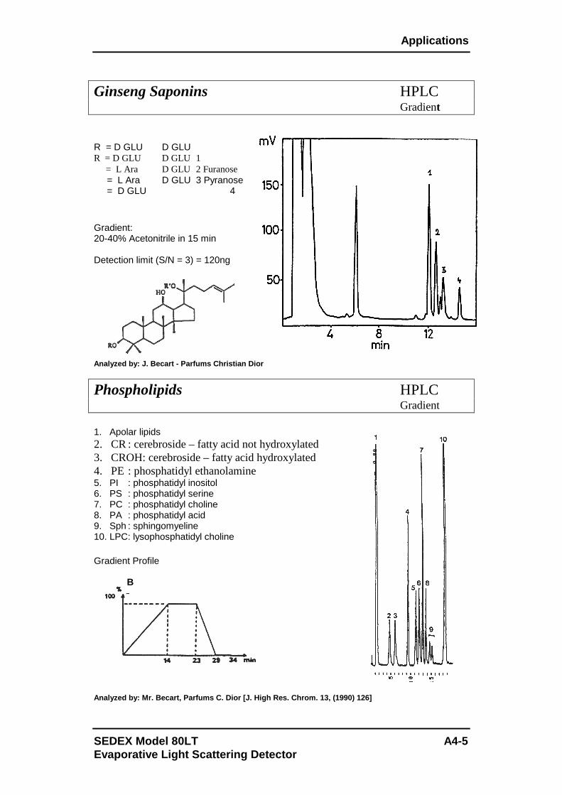
Applications
SEDEX Model 80LT A4-5 Evaporative Light Scattering Detector
Ginseng Saponins HPLC Gradient R = D GLU D GLU R = D GLU D GLU 1 = L Ara D GLU 2 Furanose = L Ara D GLU 3 Pyranose = D GLU 4 Gradient: 20-40% Acetonitrile in 15 min Detection limit (S/N = 3) = 120ng Analyzed by: J. Becart - Parfums Christian Dior
Phospholipids HPLC Gradient
1. Apolar lipids 2. CR : cerebroside – fatty acid not hydroxylated 3. CROH: cerebroside – fatty acid hydroxylated 4. PE : phosphatidyl ethanolamine 5. PI : phosphatidyl inositol 6. PS : phosphatidyl serine 7. PC : phosphatidyl choline 8. PA : phosphatidyl acid 9. Sph : sphingomyeline 10. LPC: lysophosphatidyl choline Gradient Profile Analyzed by: Mr. Becart, Parfums C. Dior [J. High R es. Chrom. 13, (1990) 126]
B
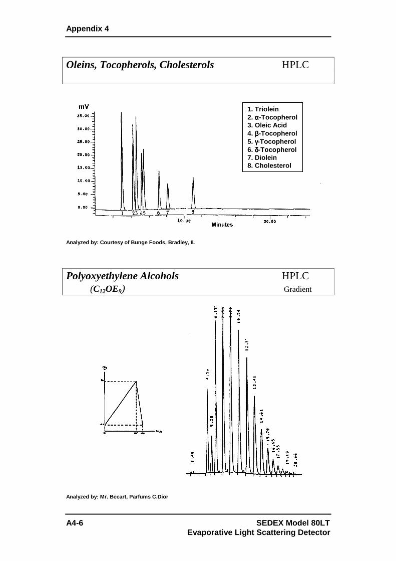
Appendix 4
A4-6 SEDEX Model 80LT Evaporative Light Scattering Detector
Oleins, Tocopherols, Cholesterols HPLC
Analyzed by: Courtesy of Bunge Foods, Bradley, IL
Polyoxyethylene Alcohols HPLC (C12OE9) Gradient Analyzed by: Mr. Becart, Parfums C.Dior
1. Triolein 2. αααα-Tocopherol 3. Oleic Acid 4. ββββ-Tocopherol 5. γγγγ-Tocopherol 6. δδδδ-Tocopherol 7. Diolein 8. Cholesterol

Applications
SEDEX Model 80LT A4-7 Evaporative Light Scattering Detector
Polyethylene Glycol PEG 400 HPLC Gradient Analyzed by: LCBA 45100 Orleans FRANCE
Underivatized Amino Acids HPLC Gradient
Analyzed by: Mr Dreux et al. - UNPUBLISHED RESULTS - SP: system peak
Gradient: Acetonitrile/Water 10/90 to 90/10 in 40 min
Gradient: H2O (+volatile ion pairing agent) 0% to 40% organic solvent in 40 min.

Appendix 4
A4-8 SEDEX Model 80LT Evaporative Light Scattering Detector
D and L Amino Acids HPLC Direct Enantiomeric separation
Analyzed by: CEA SACLAY – Service des molécules mar quées – 91191 GIF/YVETTE CEDEX – FRANCE
Underivatized Small Peptides HPLC
Dipeptides:
Tri & Tetrapeptides :

Applications
SEDEX Model 80LT A4-9 Evaporative Light Scattering Detector
Inorganic Anions HPLC
Analyzed by: LCBA 45100 Orléans FRANCE
Detergent HPLC Gradient Analyzed by: Pasteur Merieux- R & D Laboratory 6928 0 Marcy L’Etoile FRANCE
1 : Tergitol type 8 2 : Octyl B glucoside 3 : Sodium dodecyl sulfate 4 : N lauryl sarcosine 5 : Zwittergent 3 14 6 : Triton X 100 7 : Lubrol 8 : PEG 10 tridecyl ether
Gradient: 40-100 % Acetonitrile (3% min)

Appendix 4
A4-10 SEDEX Model 80LT Evaporative Light Scattering Detector
Low Temperature Operation: HPLC Ethylene Glycol
0
0,2
0,4
0,6
0,8
1
1,2
Minutes
Vol
ts
50°C
40°C
35°C
30°C
-0,006
-0,001
0,004
0,009
0,014
0,019
0,024
0,029
0,034
0 1 2 3 4 5 6 7 8 9Minutes
Vol
ts
10 µl injections (2.5 mg/L), mobile phase 100% water
Analyzed by: R. Pennanec, SEDERE Orléans
LOQ = 2.16ppm LOD = 0.65ppm
Drift Tube Temperature

Applications
SEDEX Model 80LT A4-11 Evaporative Light Scattering Detector
Low Temperature Operation: HPLC Urea
Effect of Temperature on Detector Signal
As the temperature of the detector increases, urea decomposes and its contribution to the observed signal decreases.
Analyzed by: Richard Scientific, Novato CA 94949 U

Appendix 4
A4-12 SEDEX Model 80LT Evaporative Light Scattering Detector
[This page intentionally left blank]

A5-1 SEDEX Model 80LT Evaporative Light Scattering Detector
Drivers in option can be only proposed for ELSD 80LT Detector with RS-232 activated to get a direct single-point control and digital data acquisition and to eliminate the need for A/D converter. It also makes this detector fully integrated in many HPLC equipments. The RS-232 cable connection from the detector to the PC requires a straight/direct (non-cross) serial cable bundled with the detector. If your PC has multiple COM ports, make sure you have selected the correct one.
Note: By experience, some RS-232 ports added on computers by USB modules may present some communication troubles: complete or partial miss of communication. For laptop, PCMCIA cards are recommended as no problem has been experienced so far.
The ELSD 80LT Detector is normally controlled by the keyboard on the front panel, but once it receives correct orders from the RS-232 link, the keyboard is deactivated and then the ELSD 80LT Detector can be only controlled by the PC. It avoids orders conflicts between a keyboard operator request and a PC request. This is called "distant mode" and is activated once a valid command is received. To exit "distant mode" exists the driver’s program. The Autozero cable (refer to Section 2.5.3) must be connected to a “Start” information on the controlling device (e.g. autosampler…). In this mode, the “Start” information is used as a signal synchronization for the driver. Not using it will impair the synchronization of the signal and could not generate the final report and/or impair the retention time reproducibility. Driver for EZChrom Elite™ [SEDERE Part number 85090, from Version 3.1.4] Driver for ChemStation™ [SEDERE Part number 85089, From Version B.02.01.SR1 (259)] Driver for Xcalibur™ [SEDERE Part number 85093, From Version V1.4] Clarity™ [The driver is part of Clarity from Version 3.0.2] For Installation and Operation with these Drivers, you can directly refer to their respective Operator’s Manuals. To obtain more information about Drivers, please contact your local distributor.
Appendix 5: Drivers for SEDEX Model 80LT


SEDEX Model 80LT I-1 Evaporative Light Scattering Detector
A Accessory Kit 2-1 Autozeroing the Detector 4-2 B Background Noise Test 3-11 C Carrying the Detector 2-2 Cleaning Detector 5-9 Nebulizer 5-6 Column
Connecting 2-12 Treatment 4-6
Configurations 2-1 Contents of Manual 1-6 Control Panel 3-1 D Decontaminating 5-9 Detection 1-5 Digital Display 3-1 Driver A5-1 E Electrical Connections 2-8 Electronic Noise Test 3-11 Environmental Conditions 2-5 Evaporation of the Solvent 1-4 External Autozero 2-8, 4-2 External Events 2-8 Exhaust Requirements 2-4 F Factory Method Code Screen 3-9 Filter 3-5, 4-6
Firmware version 3-9 G Gain (Temperature/Gain Screen) 3-4 Gas
Flow Problems 5-9 Flow Bypass Valve 5-9 Inlet Tube 2-6 Requirements 2-3 Supply 2-6
Gas Valve Screen 3-6 Glass Tube 1-4 Installing 2-10 I Initial Test Procedure 3-10 Installation 2-1, 2-5 Nebulizer 2-10 Integrator (Installing) 2-8 Introduction 1-1 L Laboratory Requirements 2-3 LED Screen 3-6 Lifting of Detector 2-2 Location
of Detector in Laboratory 2-5 of Offices 1-8
M Maintenance 5-1 Manual Auto-zeroing 4-2 Mobile Phase (Optimizing) 4-5 N Nebulization 1-3
Index

Index
I-2 SEDEX Model 80LT Evaporative Light Scattering Detector
Nebulizer Cleaning 5-6 Gas 2-12 Installation 2-10
Nebulizers 1-3 Noise Filter/Pressure Unit Screen 3-5 Noise Tests 3-10 to 3-13, 5-4 O Offset Screen 3-3 Operational Qualification Protocol (O.Q.) A3-3 Optimizing
Mobile Phase 4-5 Performance 4-3 Temperature 4-3
P Power Cord 2-8
Requirements 2-3 Up the Detector 2-12
Power Down Screen 3-7 Powering Down 4-7 Preparing the Unit for Operation 4-1 Pressure Unit (Noise Filter/Pressure Unit Screen) 3-5 Principle of Operation 1-2 R Recorder/Integrator (Connecting) 2-8 References 1-7 Routine Operation 4-3 RS-232 Port 2-9 S Safety Precautions iii Sample Pretreatment 4-6 Screens
External Power Down 3-7 Factory Method Code 3-9 Firmware version 3-9 Gas Valve 3-6 Noise Filter/Temperature 3-5
Offset 3-3 Serial Number 3-8
Status 3-3 Temperature/Gain 3-4 Total Lifetime Elapsed 3-8 Serial Number Screen 3-8 Shutting Down 4-7 Siphon Overflow (Installing) 2-11 Solvent Noise Test 3-12 Start-Up
Kit 2-1 Procedure 4-1
Status Screen 3-3 Stray Light Test 3-11 T Temperature/Gain Screen 3-4 Temperature (Optimizing) 4-3 Tests Background (Stray Light) Noise 3-11 Column Noise 3-13
Electronic Noise 3-11 Solvent Noise 3-12 Total Lifetime Elapsed Screen 3-8 Troubleshooting 5-3 U Unpacking 2-3 User Interface 3-3 V Venting
Exhaust Lines 2-7 Requirements 2-4
W Warnings iii Warning Symbols iv Z Zeroing the Detector 4-2
L.E.D. 3-6


