
SECURITY PERFORMANCE AND ENHANCEMENT FOR …€¦ · AMPLITUDE CODING OPTICAL CODE DIVISION...
167
SECURITY PERFORMANCE AND ENHANCEMENT FOR SPECTRAL AMPLITUDE CODING OPTICAL CODE DIVISION MULTIPLE ACCESS NETWORKS HESHAM ABDULLAH AHMED BAKARMAN THESIS SUBMITTED IN FULFILMENT FOR THE DEGREE OF DOCTOR OF PHILOSOPHY FACULTY OF ENGINEERING AND BUILT ENVIRONMENT UNIVERSITI KEBANGSAAN MALAYSIA BANGI 2011
Transcript of SECURITY PERFORMANCE AND ENHANCEMENT FOR …€¦ · AMPLITUDE CODING OPTICAL CODE DIVISION...
SECURITY PERFORMANCE AND ENHANCEMENT FOR SPECTRAL AMPLITUDE CODING OPTICAL CODE DIVISION
MULTIPLE ACCESS NETWORKS
HESHAM ABDULLAH AHMED BAKARMAN
THESIS SUBMITTED IN FULFILMENT FOR THE DEGREE OF DOCTOR OF PHILOSOPHY
FACULTY OF ENGINEERING AND BUILT ENVIRONMENT UNIVERSITI KEBANGSAAN MALAYSIA
BANGI
2011

PRESTASI DAN PENAMBAIKAN KESELAMATAN RANGKAIAN PELBAGAI CAPAIAN PEMBAHAGIAN KOD OPTIK DARI PENGKODAN
AMPLITUD SPEKTRA
HESHAM ABDULLAH AHMED BAKARMAN
TESIS YANG DIKEMUKAKAN UNTUK MEMPEROLEH IJAZAH DOKTOR FALSAFAH
FAKULTI KEJURUTERAAN DAN ALAM BINA UNIVERSITI KEBANGSAAN MALAYSIA
BANGI
2011

DECLARATION
I hereby declare that the work in this thesis is my own except for quotations and
summaries which have been duly acknowledged.
10 DECEMBER 2011 HESHAM ABDULLAH AHMED BAKARMAN P 34851

iii
AKNOWLEDGMENTS
Praise be to Allah Almighty for giving me the strength, patience and ability to complete this thesis.
I would like to express my sincere gratitude to my supervisor Professor Dr. Sahbudin Shaari, for his excellent idea, profound technical vision, invaluable guidance, many fruitful discussions and constant support in making this research possible over the years. I would like also to thank my co-supervisor Professor Dr. Mahamod Ismail for his helpful suggestions, support and co-operation throughout the study.
I am grateful to all my colleagues, friends, staff, and lecturers in Faculty of Engineering and Built Environment, Universiti Kebangsaan Malaysia and Hadhramout University of Science and Technology, Yemen for their help and support at every step during this study.
I would like to thank my beloved family for all support, patience,
understanding and being helpful throughout my study. I give my deepest gratitude and sincerest love to my parents for their love and support through my entire life. Special thank to my father for his help to solve any problem floating on the surface with my employer.
I wish to extend my grateful appreciation to all those who have contributed
directly and indirectly to the preparation of this study.
iv
ABSTRACT
In recent years, optical Code Division Multiple Access (optical CDMA) has become an interesting research area in optical communication technologies. Optical CDMA technology has obvious superiority for constructing the local area networks (LANs) and access networks in contrast to other multiplexing techniques. The need for transmission security in the developing of optical CDMA networks at the physical layer is becoming increasingly important. Spectral Amplitude Coding (SAC) is an encoding approach to implement optical CDMA networks. Although the system performance of SAC optical CDMA has been presented by many researchers, its security show has not presented widely. Therefore, there is a need to investigate the transmission security that can be provided by SAC optical CDMA. In this work, security performance of SAC optical CDMA schemes has been investigated. The eavesdropper probability of correctly detected Spectral Encoding Chip Bandwidth (SECB) pulses in a code word is investigated. The eavesdropper performance is based on tapping and observing the encoded transmitted signal using a tuning band pass filter followed by an envelope detector. The eavesdropper measures the intensity for each intercepted SECB pulse and calculates its corresponding signal to noise ratio (SNR). The eavesdropper SNR is investigated based on Modified Quadratic Congruence (MQC) code schemes. Thermal noise, shot noise and phase-induced intensity noise (PIIN) are included to be the main noise contributions. Our results showed that using unipolar optical CDMA codes schemes based on MQC and Modified Double Weight (MDW) code system enhances the security with a low cost implementation in comparison to the bipolar code schemes. Optisystem software V 7.0 is used to implement and simulate SAC optical CDMA networks, which are under this security investigation. At encoded spectral chip of 20 GHz the detected SNRs are 22 dB and 12 dB for authorized user and eavesdropper, respectively. These values are corresponding to bit error rate BERs of nearly 10-11 and 10-3, respectively. The security enhancement for SAC optical CDMA has been included in this work. One Dimension Hybrid (ODH) code signature based on combining and integrating the properties for both m-sequence and enhanced double weight (EDW) code has been assigned to the authorized user. For probability of correct detection of 0.5, an eavesdropper receiver interceptor would need to detect SNR of 11 dB. When only the authorized user is active in the network, the eavesdropper could obtain encoded spectral pulses with SNR of nearly 10 dB. Therefore, the eavesdropper probability of correct detection of nearly 0.25 is achieved. ODH code shows remarkable security improvement compared with m-sequence, EDW and 2D EDW/m-sequence, respectively.

v
ABSTRAK Di kebelakangan ini, capaian pelbagai pembahagian kod optik (CDMA optik) telah menjadi bidang yang diminati di dalam teknologi perhubungan optik.Teknologi CDMA optik ternyata mempunyai kelebihan dalam membina rangkaian-rangkaian tempatan dan rangkaian capaian dibandingkan dengan teknik-teknik pemultipleksan. Keperluan kepada keselamatan transmisi dalam membangunkan CDMA optik pada lapisan fizikal menjadi semakin penting.Pengekodan spectra amplitud (SAC) adalah satu kaedah dalam implementasi rangkaian CDMA optik. Walau pun begitu, aspek keselamatan masih kurang ditekankan secara meluas dalam sistem SAC-CDMA optik ini dan perlu dikaji lebih mendalam. Kebarangkalian curitalian untuk mengesan denyut-denyut lebarjalur cip pengkodan spektra di dalam satu kata kod dengan betul (SECB) adalah dikaji. Prestasi pencuritalian ini adalah berdasarkan tap dan pemerhatian ke atas isyarat yang dihantar yang dikodkan dengan menggunakan penalaan penuras laluan jalur diikuti oleh sebuah pengesan envelop. Pencuritalian mengukur intensiti setiap denyut SECB yang dipintas dan mengira nilai isyarat ke hingar (SNR) yang berkaitan. Nilai SNR curitalian ini berdasarkan skema kod ‘modified quadratic congruence’ (MQC). Bisingan termal, bisingan ‘shot’, dan bisingan intensity aruhan fasa adalah dimasukkan sebagai keterlibatan utama bisingan. Keputusan menunjukkan menggunakan kod unipolar skema kod CDMA berdasarkan MQC dan pemberat pendua diubahsuai (MDW) akan menambahkan keselamatan dengan kos yang rendah dibandingkan dengan skema kod bipolar. Perisian Optisystem V7.0 adalah digunakan terutamanya untuk implementasi dan simulasi rangkaian SAC- CDMA optik, di mana di bawah penyiasatan keselematan. Pada cip spektra terkod 20 GHz, SNR yang di kesan adalah masing-masing 22dB dan 12 db untuk pengguna dan pencuri talian. Ini setara dengan nilai BER masing-masing berhampiran dengan 1011 dan 10-3. Penambahan keselamatan untuk SAC-CDMA optik telah juga dilibatkan dalam kerja ini. Tandatangan kod hibrid satu dimensi (ODH) berdasarkan kombinasi dan integrasi sifat-sifat untuk kedua-dua kod m-sequence dan enhance double weight EDW telah di tetapkan kepada pengguna yang dibenarkan. Untuk kebarangkalian untuk pengesan betul 0.5, satu penerima pemintas curitalian memerlukan untuk mengesan SNR sebanyak 11 dB. Jika hanya pengguna yang dibenarkan aktif dalam talian, pencuri talian boleh memperoleh kod dengan SNR hanya di sekitar 10dB. Oleh itu, kebarangkalian kecuriantalian dengan pengesanan yang betul di sekitar 0.25 diperolehi. Kod ODH telah menunjukkan penambahbaikan keselamatan yang ketara jika di bandingkan dengan m-sequence, EDW dan 2D EDW/ m-sequence.
vi
CONTENTS
Page
DECLARATION
ii
ACKNOWLEDGEMENT
iii
ABSTRACT
iv
ABSTRAK
v
CONTENTS
vi
LIST OF TABLES
x
LIST OF ILLUSTRATIONS
xi
LIST OF ABBREVIATIONS
xv
CHAPTER I INTRODUCTION
1.1 Background
1
1.2 Problems Statement
3
1.3 Objectives
5
1.4 Scope of Study
6
1.5 Summary of Thesis Contributions
8
1.6 Thesis Organization
10
CHAPTER II
OPTICAL CDMA
2.1 Introduction 11
2.2 Multiplexing and Multiple Access Techniques
11
2.2.1 Time division multiplexing (TDM) 2.2.2 Frequency division multiplexing (FDM) 2.2.3 Wavelength division multiplexing (WDM) 2.2.4 Code division multiplexing access (CDMA)
12 13 14 15
2.3 Optical Code Division Multiple Access (Optical CDMA)
16
2.3.1 Optical CDMA fundamentals 2.3.2 Optical CDMA system characteristics 2.3.3 Optical CDMA systems classifications
18 18 20
vii
2.4 Types of Optical CDMA Codes
22
2.4.1 Coherent optical CDMA systems 2.4.2 Incoherent optical CDMA systems
22 26
2.5 SAC Optical CDMA Codes
33
2.5.1 Optical orthogonal codes 2.5.2 Prime codes 2.5.3 Hadamard code 2.5.4 Modified quadratic congruence code (MQC) 2.5.5 Maximal Length Sequences (M-Sequences) 2.5.6 Double Weight (DW) Codes 2.5.7 Modified Double Weight (MDW) Codes 2.5.8 Enhanced Double Weight (EDW) Codes
35 36 37 38
39 41 43 45
2.6
Overview of the vulnerabilities in Optical Communication Networks
48
2.7 Summary
49
CHAPTER III
SECURITY IN OPTICAL COMMUNICATION NETWORKS
3.1 Introduction
51
3.2 Network Security Issues
51
3.2.1 Security definitions 3.2.2 Network security 3.2.3 Network fundamentals 3.2.4 Network topology Implications 3.2.5 Security service objectives 3.2.6 Security threats
51 52 52 52 54 55
3.3 Tapping and Detecting Optical Signals
56
3.4 Eavesdropper Code Pulse Detector
58
3.5 Eavesdropper Strategy
60
3.6 Eavesdropper’s Probability of Correct Detection
61
3.7 Simulation Software and Parameters Used
66
3.8 Tapping Encoded Spectral Chip Bandwidth from SAC Optical CDMA Systems
67
3.9 Security and Performance Tradeoffs
71
3.10 Summary 77
viii
CHAPTER IV
SECURITY PERFORMANCE FOR SPECTRAL AMPLITUDE CODE OPTICAL CDMA
4.1 Introduction
78
4.2 Probability of The Eavesdropper Encoded Pulses Correct Detection
79
4.3 Eavesdropper SNR: a Spectrally Encoded Pulse Bandwidth Effects
81
4.3.1 Eavesdropper receiver and noise considerations 4.3.2 Eavesdropper SNR analysis 4.3.3 Eavesdropper Performance analysis
82 83 90
4.4 Simulation of Transmission Security Performance for SAC Optical CDMA Systems
94
4.4.1 Simulation set up 4.4.2 Eavesdropper simulation results
95 97
4.5 Summary 103
CHAPTER V
SECURITY ENHANCEMENT OF SAC OPTICAL CDMA USING HYBRID ENCODING SYSTEMS
5.1 Introduction 104
5.2 Conventional Spectral Amplitude Coding Optical CDMA Systems
105
5.2.1 M-sequence codes 5.2.2 Enhanced double weight (EDW)
106 108
5.3 2-D Hybrid EDW/M.sequence
109
5.3.1 Code design 5.3.2 Security performance
109 112
5.4 One Dimension Hybrid (ODH) EDW/M-sequence System
114
5.4.1 Code design 5.4.2 ODH security performance 5.4.3 Simulation
114 120 124
5.5 Summary
133
ix
CHAPTER VI CONCLUSION AND SUGGESTION FOR FUTURE WORK
6.1 Conclusion
134
6.2 Suggestions for Future Work
137
REFERENCES
139
APPENDICES
A
List of Publications
149

x
LIST OF TABLES
Table No. Page 2.1 Advantages and disadvantages of the coherent and incoherent
optical CDMA schemes
32
2.2 Properties of several SAC optical CDMA systems
49
3.1 Optical networks attack methods
58
3.2 Decision possibilities corresponding to detection threshold
62
3.3 The basic MDW code denoted by (9, 4, 1)
68
5.1 The basic EDW code denoted by (6,3, 1)
108

xi
LIST OF ILLUSTRATIONS Figure No. Page 1.1 Research scope of study 6
2.1 Time-division multiplexing (TDM)
12
2.2 Input signal spectrums are swifted in a number of various frequency ranges
13
2.3 Wavelength-division multiplexing (WDM)
14
2.4 Code Division Multiple Access system block diagram
16
2.5 Optical Code Division Multiple Access schematic diagram block diagram
17
2.6 Optical CDMA system classifications
21
2.7 Block diagram of (SPC-OCDMA) system architecture
23
2.8 Block diagram of (TPC-optical CDMA) system architecture
25
2.9 Representations of two code sequences for temporal spreading optical CDMA
27
2.10 Representations of two code sequences for wavelength-hopping time-spreading (WHTS) optical CDMA
28
2.11 Schematic block diagram of a WHTS optical CDMA network
29
2.12 Spectral amplitude coding (SAC) using diffraction gratings and spatial masks
30
2.13 Block diagram of encoding/decoding for SAC optical CDMA system
31
2.14 Four stage maximal length linear feedback shift-register
40
3.1 OSI Reference Model
53
3.2 Point to point star topology
54
3.3 Broadcast network topologies
54
3.4 Models of network attacks
56
3.5 Simple optical fiber tap by bending that allows the leaking of light
57
3.6 (a) micro-bend clamping tapping device, and (b) macro-bend tapping device
57
3.7
Places for an eavesdropper to attack and tap optical CDMA encoded pulses
60
3.8 Eavesdropper code interceptor structure
61
xii
3.9
Probability of detection versus encoded pulse SNR, for several FP values
63
3.10 Code intercepting detector performances using optical matched filter with envelope detection
68
3.11 Simulation setup for MDW optical CDMA system with eavesdropping from user 1
69
3.12 Encoded spectrum detected by eavesdropper with 20 % tapping efficiency
70
3.13 Eavesdropper-tapping performance
71
3.14 Effect of combining multiple code pulses for both coherent and incoherent detection schemes
73
3.15 Per chip code SNR as a function of theoretical system capacity
74
3.16 Per chip code SNR as a function of theoretical system capacity for different specified authorized SNRs
74
3.17 BERs as a function of theoretical system capacity for different specified authorized SNRs
75
3.18 Security impact over system performance for spectral amplitude optical CDMA based on MDW code systems
76
3.19 Eavesdropper SNR vs bit rates 77
4.1 Code intercepting detector performances using optical matched filter with envelope detection
80
4.2 MQC eavesdropper performance
81
4.3 The system architecture of spectral amplitude code optical CDMA system network
83
4.4 The PSD of the received signal ( )r v 87
4.5 Noise contributions versus the received optical power in eavesdropper receiver
90
4.6 Eavesdropper performance with variation of encoded spectral chip bandwidth
91
4.7 Authorized user and eavesdropper BER performance
92
4.8 Code dimension effects on eavesdropper performance
93
4.9 Eavesdropper performance for unipolar and bipolar optical CDMA codes
94
4.10 Simulation setup for MDW optical CDMA system with eavesdropping from user
95
xiii
4.11 Simulation set up for MQC optical CDMA system with eavesdropping from user
97
4.12 All users encoded spectrum
97
4.13 All users encoded spectrum detected by eavesdropper
98
4.14 Isolated user spectral chips for user 1
99
4.15 Effects of single spectral chip bandwidth on eavesdropper
99
4.16 Encoded spectrum detected by eavesdropper: (a) all users, (b) user 1, (c) user 5 and (d) user 9
101
4.17 User 1 encode spectral chips
102
4.18 Detected SNRs vs. encoded pulses bandwidth authorized user
102
5.1 Code matrices of the 2-D hybrid EDW/M-seq. optical CDMA for E=6 and N=3
110
5.2 Block diagram of hybrid EDW/M-seq. optical CDMA
110
5.3 BER versus active users
111
5.4 Eavesdropper code interceptor structure
112
5.5 Code intercepting detector performances using optical matched filter with envelope detection
113
5.6 The representation of the ODH users’ code sequences: (a) first user, (b) second user, and (c) third user
120
5.7 Eavesdropper performance based on detection theory
122
5.8 Eavesdropper SNR as a function of encoded spectral chip
124
5.9 ODH system block diagram
125
5.10 (a) ODH encoder and (b) ODH direct detection decoder
126
5.11 OSA measurements for encoded spectral chips (a) all users (b) user 1, (c) user 2, and (d) user 3
127
5.12 OSA measurements for encoded spectral chips (a) all users (b) users 1 & 2, (c) users 1 & 3, and (d) users 2 & 3
127
5.13 Encoded spectral pulses after eavesdropping from user one in an isolated situation (only user one is active in the network)
128
5.14 Eye patterns (a) minimum for eavesdropper, (b) maximum for eavesdropper and (c) authorized user
129
5.15 Encoded spectral pulses after eavesdropping from user one (when only two users are active in the network)
130
5.16 Encoded spectral pulses after eavesdropping from user one (when all users are active in the network)
130

xiv
5.17 Eye patterns when two users are active (a) minimum for
eavesdropper, (b) maximum for eavesdropper and (c) authorized user
131
5.18 Eye patterns when all users are active (a) minimum for eavesdropper, (b) maximum for eavesdropper and (c) authorized user
131
5.19 Encoded spectral chip bandwidth effect
132
5.20 Eye patterns when user one is active at spectral chip of 20 GHz for (a) eavesdropper and (b) authorized user
133

xv
LIST OF ABBREVIATIONS ASE Amplified Spontaneous Emission
BER Bit Error Rate
CDMA Code Division Multiple Access
CO Central Office
DW Double Weight
DWDM Dense Wavelength Division Multiplexing
EDW Enhanced Double Weight
FDMA Frequency Division Multiple Access
FTTH Fiber to the Home
GF Galois Field
LED Light Emitting Diode
MAI Multiple Access Interference
MDW Modified Double Weight
MFH Modified Frequency Hopping
MQC Modified Quadratic Congruence
M-Sequence Maximal Length Sequences
NDSF Non-Dispersion Shifted Fiber
NRZ Non-Return to Zero
OCDM Optical Code Division Multiplexing
OCDMA Optical Code Division Multiple Access
ODH One Dimension Hybrid
OOC Optical Orthogonal Codes
OOK On/Off Keying
OSCDMA Optical Spectrum Code Division Multiple Access
OSNR Optical Signal to Noise Ratio
PIIN Phase Induced Intensity Noise
PMD Polarization Mode Dispersion
PON Passive Optical Networks
PRBS Pseudo Random Binary Sequence
PSD Power Spectral Density
PSK Phase Shift Keying

xvi
SNR Signal-to-Noise Ratio
TDMA Time Division Multiple Access
WDM Wavelength Division Multiplexing
WDMA Wavelength Division Multiple Access
CHAPTER I
INTRODUCTION
1.1 BACKGROUND
In the last few years, the increased demand of data services has driven a
corresponding explosion in transportable bandwidth, most of which involve sensitive
information, personal data, bank accounts, credit card numbers, proprietary
documents, and more (Kartalopoulos 2009). From a security perspective, these rapid
growths in data services need to be well secured from any type of attacks. As a result,
network security concerns have recently been increased due to the huge amount of
information that flows in a communication media.
In general, there are three types of network security concern in
communications: physical network, user data, and network management and
provisioning security. Physical layer security and data-level security correspond to
where in the communication network the security is implemented. Physical layer
security defines the transmission security at the physical layer of the network and is
concerned with protecting the physical transmissions in transit from interception and
detection by hostile eavesdroppers and adversaries. Data-level security focuses on
information security that exists in the presentation layer of the network and relies on
the cryptographic approach to encrypt and decrypt data. Information security means
securing information and information systems from illegal access, disclosure,
disruption, usage and modification, examination, inspection, recording or destruction
(Allen 2001). Network management and provisioning pertains to network attacks to
disable, manage and reprovision nodes (Kartalopoulos 2007).

2
For a long time, there has been an on-going misconception that optical fiber
communication is a secure communication platform. Assuming there is possible
access to the fiber link such as bend tapping, optical communications networks are
susceptible to the same security threats as wireless communications. Security over the
optical communications network gives numerous challenges to both network
providers and intruders, and experiences the same sensitivities and vulnerabilities as
wireless communications (Cederlof & Larsson 2008).
At the latter part of 1970, Code Division Multiple Access (CDMA) technology
was initially developed for wireless military telecommunications to increase the
robustness of information security. It is also called spread spectrum technique and has
been widely applied to the fields of satellite communication, wireless communication
and mobile communication (Prasad & Ojanpera 1998). Optical CDMA scheme is
resulting from combining the advantages of the predominance of electrical CDMA as
well as asynchronously random access with the tremendous bandwidth of fiber-optic
and optical-signal processing devices, in which code multiplexing and transmission
are performed in the optical domain. Therefore, an optical fiber communication
network with more powerful function could be implemented, where passive optical-
access networks, LAN and WAN can be built up by using optical CDMA technology.
Optical CDMA is a kind of multiplexing and networking for optical
communication systems and networks in which optical signals are performed by
encoding/decoding data employing simple and low cost passive optical components.
Its main advantages include asynchronous random access, supporting multiple rates,
good compatibility with WDM and TDM, flexible networking, and providing some
privacy of transmission information.
In the literature where optical CDMA technologies and theories are introduced
and investigated, information and transmission security are considered to be the most
intrinsic advantages for optical CDMA networks (Iversen & Hampicke 1995;
Karafolas & Uttamchandani 1996; Sampson et al. 1997; Tancevski et al. 1995; Torres
et al. 2002). Some of these researches have focused on the data link layer security
which relies on the cryptographic approach and others on the network physical layer

3
security that defines transmission security in the encoding approach (Kamath et al.
2004; Mohamed et al. 2006; Shalaby 2003; Sun et al. 2007).
1.2 PROBLEM STATEMENT
Optical CDMA has become a promising technology to implement truly all-optical
communication and networking that use optical signal processing directly combining
the advantages of electrical CDMA with the bandwidth predominance of fiber-optic
and optical-signal processing devices. The passive optical-access networks, LAN and
WAN, can be built up by using optical CDMA technology.
The potential provided by optical CDMA for enhanced information security is
frequently mentioned in addition to other possible advantages, such as simplified and
decentralized network control, improved spectral efficiency, and increased versatility
in the bandwidth partition that can be provisioned. Logically, the optical CDMA
encoded signals manifest itself as a noise-like waveform that possibly will not be
available to an eavesdropper without knowing and understanding of the assigned code.
Studies have previously demonstrated there is no security at all in most coded optical
CDMA for a single-user system employing on-off keying (OOK) (Shake 2005b).
Lately, to figure out this problem, a code switching scheme (or 2-code keying)
was proposed, and its performance was evaluated theoretically (Mohamed et al. 2006;
Shake 2005a). Experimental demonstration of the code switching system was carried
out by utilizing coherent optical CDMA with a short coherent optical pulse (Leaird et
al. 2005). However, a band-limited photodiode was assumed for eavesdropping and
the degree of security was only investigated by measuring eye-diagrams at back-to-
back configuration. An M-code keying optical CDMA system with parallel
encoders/decoders presented by (Qin et al. 2008), and quantitatively analyzed its
security performance. The results show that the security performance is slightly
improved, but does not greatly enhance its security performance compared with the
two-code keying optical CDMA system. Even though both the switching code keyings
have better security compared to the OOK OCDMA system, their costs should be
4
taken into account. The increase in codes will increase multiple access interference
(MAI), which may reduce the number of active users and many codes are needed.
An alternative to the huge code-space size techniques such as the wavelength
hopping/time spreading (Fathallah et al. 1999; Yegnanarayanan et al. 2000), or
spectral-phase coding (Salehi et al. 1990) for network protection against
eavesdropping by using the spectral amplitude code optical CDMA approach in which
a unipolar M-sequence is used for encoding/decoding processes (Yao-Tang et al.
2007). Security enhancement, based on reconfigurable AWG-based codec, has been
implemented by controlling the processing time of the optical switches and the control
registers. Since, optical switches have a shorter processing time than electrical
devices, one needs to enable the processing time of the current electrical shift registers
to move toward that of the optical switches to realize the optimum reconfigurable
processing time throughout the code change.
Some data confidentiality measurements have been reported based on a
wavelength/time optical CDMA system where the eavesdropper is always confronted
with severe multi-access interference (MAI) (Mendez et al. 2005). This confidentiality
will no longer be true, if at least one user in the network is active or when the
eavesdropper can tap the transmitted information by isolating the intended user.
Optical CDMA technology has obvious superiority for constructing the local
area networks (LANs) and access networks in contrast to other multiplexing
techniques. The need for the transmission security in the developing of optical CDMA
networks at the physical layer is becoming increasingly important. Spectral amplitude
coding (SAC) is an encoding approach to implement optical CDMA networks.
Although the system performance of SAC optical CDMA has been presented by many
researchers, its security show has not been presented widely. Therefore, there is a need
to investigate the transmission security that can be provided by SAC optical CDMA.
The security issues of optical CDMA system employing the incoherent bipolar
complementary spectrally optical encoder and decoder were investigated by Chung et
al. 2008. It showed that wideband in a single spectral chip enhances the performance
5
of both the authorized user and eavesdropper. In addition, the bipolar signaling has a
3-dB Signal-to-Noise Ratio (SNR) advantage over the on-off keying system with high
cost implementation because each transmitter sends energy for both “0” and “1” bit
(Nguyen et al. 1995). From the security viewpoint, one should minimize the
eavesdropper ability to detect code word pulses by controlling the authorized
performance to reasonable throughput.
There are four basic goals related to information security services of any
communications network: confidentiality, integrity, availability and authenticity
(Dhillon 2007). Confidentiality is the term used to avoid the expose of information to
unofficial parties, individuals or systems. Integrity means that data cannot be adapted
or changed without authorization permission. Availability is the term to guarantee that
the data must be available whenever it is required. Certifying availability also involves
avoiding denial-of-service attacks. Authenticity is to make sure that the information,
dealings, communications or documents (electronic or physical) are authentic and
legal.
1.3 OBJECTIVES
The main objective of this research is to investigate and enhance security performance
of optical CDMA based on spectral amplitude code schemes. The specific objectives
of this thesis include:
a. To investigate the eavesdropper performance based on calculating the
probability of correctly detected the encoding spectral chip bandwidth (ESCB)
pulses in a SAC optical CDMA code address;
b. To investigate the effects of the encoding spectral chip bandwidth (ESCB) for
unipolar spectral amplitude code SAC schemes, such as MDW, EDW, M-
sequence, and MQC code schemes;
c. To enhance security performance based on hybrid SAC optical CDMA
systems using One Dimension Hybrid (ODH) and two dimensions hybrid code
schemes.

6
1.4 SCOPE OF STUDY
In this study, we focus on transmission security issues of spectral amplitude code
systems for optical CDMA networks. We concentrate on the physical layer security
which defines the transmission security at the physical layer of the network and is
concerned with protecting the physical transmissions from interception and detection
by eavesdroppers and adversaries. Figure 1.1 shows the scope of study structure of
this research which has three main stages. The first stage is focused on the
implementation of the optical CDMA, based on SAC schemes that will be used in this
work. Modified Double Weight (MDW), Enhanced Double Weight (EDW) and
Modified Quadratic Congruence (MQC) codes have been implemented. The second
stage concentrates on the theoretical and simulation analysis to investigate the
transmission security performance of the eavesdropper. The security enhancement is
demonstrated in the third stage, where hybrid SAC systems have been implemented
with different dimensions.
Figure 1.1 Scope of the study
The eavesdropper interception strategy is to tap and observe the encoded
transmitted signal using a tuning band pass filter followed by an envelope detector.
The eavesdropper measures the intensity for each intercepted ESCB pulse and
7
calculates its corresponding Signal to Noise Ratio (SNR). The eavesdropper
probability of correctly detected spectral encoding chip bandwidth (ESCB) pulses in
an SAC optical CDMA code word is examined based on classical detection theory. In
this calculation, the eavesdropper is required to know or estimate such parameters as
the code weight W, code length N, eavesdropper SNR and detection threshold.
Different conventional SAC code schemes, such as MDW, EDW and MQC, have
been used to evaluate the eavesdropper transmission security performance.
To investigate the effect of the encoded spectral chip bandwidth (ESCB) on
transmission security performance, the eavesdropper SNR is derived based on
Modified Quadratic Congruence (MQC) code schemes. Thermal noise, shot noise and
phase-induced intensity noise (PIIN) are included to be the main noise contributions.
The eavesdropper interceptor filters the received signal with pass band filter (direct
single spectral chip decoder) which is spectrally matched with that of the authorized
decoder spectral chip bandwidth. The output from this decoder is detected by a
photodetector where the received intensity is converted and processed electrically by
decision circuit. In addition to that, this analysis has been simulated by using
commercial simulation software, OptiSystem Version 7.0. The implemented network
layout parameters were activated and specified according to the typical industry
values to simulate the real environment as close as possible. Our results show that
using unipolar optical CDMA code schemes based on MDW code system enhances
the security with a low cost implementation in comparison to the bipolar ones.
The transmission security enhancement for SAC optical CDMA has been
included in this work. One dimension hybrid (ODH) code signature based on
combining and integrating the properties for both M-sequence and enhanced double
weight (EDW) code has been assigned to the authorized user. The hybrid code will
add encoding complexity for special authorized users which will make the
eavesdropper code word interception more complicated due to the code size
expansion. Therefore, both the eavesdropper probability of correctly detected encoded
spectral encoding chip bandwidth (ESCB) and the effect of the (ESCB) are presented
for these hybrid SAC optical CDMA codes.

8
1.5 SUMMARY OF THESIS CONTRIBUTIONS
We have focused on the physical layer security which defines the transmission
security at the physical layer of the network and is concerned with protecting the
physical transmissions from interception and detection by eavesdroppers and
adversaries. The major contributions of this research could be summaries as follows:
a. Eavesdropper’s probability of correct detection based on SAC optical CDMA
The transmission security issues of spectral amplitude code systems for optical
CDMA networks have been investigated. We have used several SAC codes to
implemented optical CDMA networks. Based on the proposed eavesdropper code
interceptor, we have assumed that the eavesdropper could isolate the intended
authorized user, which is considered to be the worst case for interception. The
structure of the eavesdropper receiver is quite simple. It filters the received signal with
direct spectral chip decoder, such as band pass filter (BPF), which is spectrally
matched with that of the authorized encoded spectral chip. The remaining of the
eavesdropper interceptor consists of a photodetector operating as a square-law
envelope detector to detect the output of the matched BPF, a low pass filter with a cut
off electrical bandwidth approximately equal to 75 % of the user data bit rate and a
comparator that evaluate the integrator output against a threshold value in order to
decide if a signal is received for each spectral chip code pulse.
We have introduced the eavesdropper performance based on evaluating the
probability of correct detection for the encoded spectral chip bandwidths (ESCB),
which represents the SAC user’s code sequence. This probability is adapted from the
classical detection analysis that can be calculated by knowing the probability of
missing a transmitted encoded pulse in a given time bin MP and the probability of
falsely detecting a pulse in a bin where none was transmitted FP . For probability of
correct detection of 0.5, an eavesdropper receiver interceptor would need to detect
SNRs of 7, 8, 8.3, 9.3 and 11 dB for EDW, MDW, MQC, 2-D EDW/M-sequence and
9
ODH SAC code systems. Therefore, the proposed hybrid code systems showed
remarkable security improvement compared with the conventional codes.
b. Eavesdropper SNR: a spectrally encoded pulse bandwidth effects
We have investigated the effect of the encoded spectral chip bandwidth (ESCB) on
transmission security performance, the eavesdropper SNR is derived based on
modified quadratic congruence (MQC) code schemes. In addition, this analysis has
been simulated by using commercial simulation software, OptiSystem Version 7.0.
Increasing the code dimension and decreasing the ESCB enhanced transmission
security. We have shown that the unipolar SAC optical CDMA code schemes based
on MDW code system enhanced the security with a low cost implementation in
comparison to the bipolar codes. Both analytical and simulation results are close to
each other.
c. Transmission security enhancement using hybrid SAC optical CDMA code systems
The enhancement of the transmission security of the SAC optical CDMA has been
presented. The enhancement has been achieved by proposing hybrid SAC optical
CDMA schemes. One dimension hybrid (ODH) EDW/M-sequence and two
dimensions 2-D EDW/M-sequence code systems have been implemented to provide a
degree of transmission security for SAC optical CDMA. These two approaches have
been implemented by combining and integrating the properties for both M-sequence
and EDW codes. In the ODH code design, we have introduced an easy method to
construct the M-sequence code sequences for any number of (r) and maintained the
same code properties. This new generation method will ease the construction of ODH
mathematical model, and make it more convenient. Based on ODH, we have shown
that when only user one is active in the network, the eavesdropper could obtain
encoded spectral pulses with SNR of nearly 10 dB, which could achieve probability of
correct detection of 0.25.

10
1.6 THESIS ORGANIZATION
This thesis is divided into six chapters. Chapter one presents a brief overview on the
research background and problem statement regarding the security issues in an optical
communication networks. The thesis objectives, scope of the study and the proposed
methodology have been summarized. The second chapter includes the literature
survey of optical CDMA system which includes classification of optical CDMA
systems, based on SAC schemes, and types of codes used in this work. In the third
chapter, security in optical communication networks is given, which includes tapping
and detection strategies provided by eavesdroppers. In the fourth chapter, security
performance is investigated based on the probability of correct code pulse from the
transmitted encoded signal. The effect of spectral encoded pulse bandwidth is
demonstrated by both theoretical and simulation analysis. The fifth chapter analyzes
the security enhancement for SAC optical CDMA systems based on one-dimensional
hybrid ODH and two-dimensional 2-D EDW/M-sequence code schemes. Finally, the
sixth chapter includes conclusion and areas suggested for further research.

CHAPTER II
OPTICAL CDMA
2.1 INTRODUCTION
The optical communications networks are starting to assume an important
responsibility as universal information infrastructures lead to the information
revolution. This chapter aims to review the main issues related to optical CDMA
technologies and provides a detail description about the multiplexing and multiple
access technologies. Various existing multiplexing and multiple-access techniques are
discussed with concentration on four main types of the multiplexing techniques in
communication systems. Then, brief history about optical CDMA foundation, the
fundamental principles of optical CDMA, advantages of optical CDMA, and encoding
and decoding techniques are presented. Several optical CDMA codes and their
properties are discussed, especially those related to spectral amplitude code schemes
that are under security analysis study in this thesis.
2.2 MULTIPLEXING AND MULTIPLE ACCESS TECHNIQUES
In telecommunications, multiplexing techniques represent one of the most essential
functions of access networks where two or more independent analog signals or digital
information are combined into one signal over a common medium. Multiple-access
networks offer a random bidirectional access to each subscriber. Each subscriber can
receive and transmit information to any other subscriber of the network at all times.
Multiple access techniques allow an expensive available resource communication
medium to be shared between different subscribers, greatly increasing transmission
capacity and reducing system costs (Sari et al. 2000). There are four main types of
12
multiplexing techniques in communication systems; they are Time Division
Multiplexing (TDM), Frequency Division Multiplexing (FDM), Wavelength Division
Multiplexing (WDM) and Code Division Multiplexing (CDM). There are also other
types of multiplexing techniques such as polarization mode multiplexing and spatial
multiplexing.
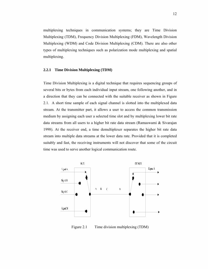
2.2.1 Time Division Multiplexing (TDM)
Time Division Multiplexing is a digital technique that requires sequencing groups of
several bits or bytes from each individual input stream, one following another, and in
a direction that they can be connected with the suitable receiver as shown in Figure
2.1. A short time sample of each signal channel is slotted into the multiplexed data
stream. At the transmitter part, it allows a user to access the common transmission
medium by assigning each user a selected time slot and by multiplexing lower bit rate
data streams from all users to a higher bit rate data stream (Ramaswami & Sivarajan
1998). At the receiver end, a time demultiplexer separates the higher bit rate data
stream into multiple data streams at the lower data rate. Provided that it is completed
suitably and fast, the receiving instruments will not discover that some of the circuit
time was used to serve another logical communication route.
Figure 2.1 Time division multiplexing (TDM)

13
2.2.2 Frequency Division Multiplexing (FDM)
Frequency-division multiplexing (FDM) is naturally an analog technology that
accomplishes the mixing of several digital signals into one medium by launching
signals in several separate frequency ranges over that medium as shown in Figure 2.2.
At the transmitter, the simultaneous transmission of multiple separate signals through
a shared medium, such as a wire or optical fiber, by modulating the separate signals
into discrete frequency bands, and summing those outcomes linearly either before
transmission or within the medium. At the receiver, equipment separates the
multiplexed signals by frequency passing or rejecting filters, and demodulates the
results independently. Each in a suitable method for the modulation system used for
that band or group (DeLange 1970).
Figure 2.2 Input signal spectrums are swifted in a number of various frequency ranges
FDM was previously the establishment of the long distance telephone
technique. Other examples of FDM include ordinary radio, television, and cable
service. Both transmitters and receivers do not need to be close to each other. Even
though TDM lends itself to the manipulation of digital data due to the recent
enhancements in its several forms, but the low cost and high quality of on-hand FDM
apparatus particularly that considered for television signals make FDM apparatus
performs satisfactorily, and can be used as an alternative for various intentions.
14
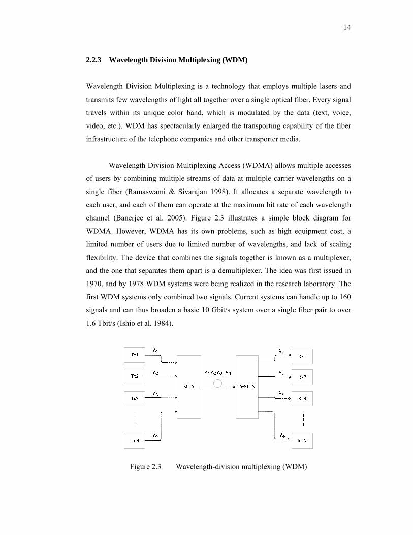
2.2.3 Wavelength Division Multiplexing (WDM)
Wavelength Division Multiplexing is a technology that employs multiple lasers and
transmits few wavelengths of light all together over a single optical fiber. Every signal
travels within its unique color band, which is modulated by the data (text, voice,
video, etc.). WDM has spectacularly enlarged the transporting capability of the fiber
infrastructure of the telephone companies and other transporter media.
Wavelength Division Multiplexing Access (WDMA) allows multiple accesses
of users by combining multiple streams of data at multiple carrier wavelengths on a
single fiber (Ramaswami & Sivarajan 1998). It allocates a separate wavelength to
each user, and each of them can operate at the maximum bit rate of each wavelength
channel (Banerjee et al. 2005). Figure 2.3 illustrates a simple block diagram for
WDMA. However, WDMA has its own problems, such as high equipment cost, a
limited number of users due to limited number of wavelengths, and lack of scaling
flexibility. The device that combines the signals together is known as a multiplexer,
and the one that separates them apart is a demultiplexer. The idea was first issued in
1970, and by 1978 WDM systems were being realized in the research laboratory. The
first WDM systems only combined two signals. Current systems can handle up to 160
signals and can thus broaden a basic 10 Gbit/s system over a single fiber pair to over
1.6 Tbit/s (Ishio et al. 1984).
Figure 2.3 Wavelength-division multiplexing (WDM)

15
2.2.4 Code Division Multiplexing Access (CDMA)
Code Division Multiple Access is a technique for transporting multiple digital signals
simultaneously over the same channel media (the same carrier frequency). The most
widely known application of CDMA is for cell phones as well as in various radio
communications systems. In data communication, one of the main basic ideas is the
concept of enabling several transmitters to send information simultaneously over a
single communication channel. This lets various users to share a bandwidth. This
concept is called multiplexing, where the transmitter encodes the signal using a
pseudorandom sequence which the receiver also distinguishes and can use to decode
the received signal. Each different arbitrary sequence matches to a different
communication channel.
CDMA utilizes spread-spectrum technology and a particular coding system. A
spread spectrum technique spreads the bandwidth of the data consistently for the same
transmitted power (Viterbi 1995). Each transmitter is allocated a code to enable
multiple users to be multiplexed over the same physical channel medium. By contrast,
time division multiple access (TDMA) separates access by time, while frequency-
division multiple access (FDMA) separates it by frequency. CDMA is a figure of
spread-spectrum signaling, because the modulated encoded signals have a much
higher data bandwidth than the data being communicated (Ipatov 2005).
CDMA neither need the bandwidth allocation of FDMA, nor the time
synchronization of the individual users needed in TDMA. A CDMA user has full
bandwidth attainable, but the quality of the communication declines with a growing
number of users. As shown in Figure 2.4, each user has its own pseudorandom noise
(PN) code, uses the same RF code and transmits simultaneously (asynchronous or
synchronous). The set of PN codes must have autocorrelation for good
synchronization and low cross correlation for low Multiple Access Interference
(MAI). Useful codes are Gold and Kasami codes (asynchronous CDMA) and
Hadamard-Walsh codes (synchronous CDMA). The detector receives a signal that
contains the total of all users’ signals, which overlap in time and frequency and
introduce the major contribution of MAI that restricts the performance capacity of the
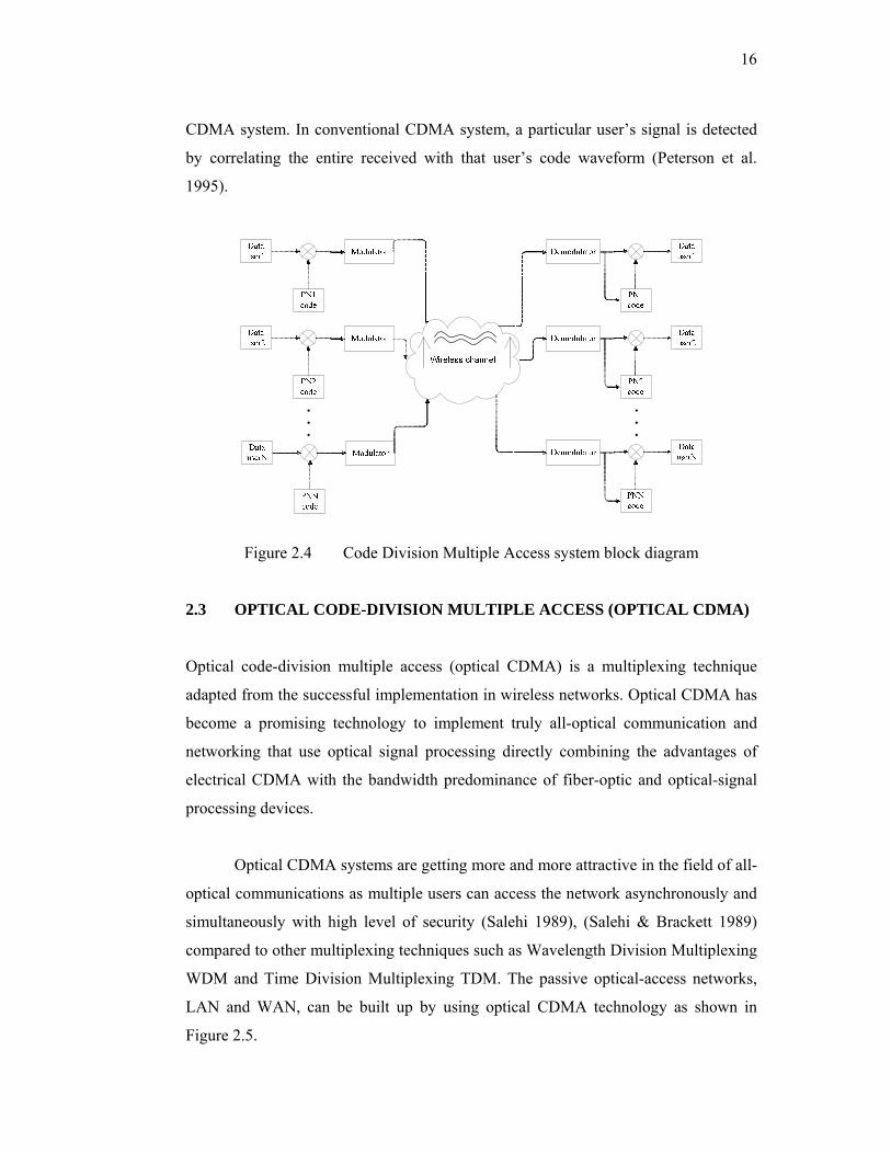
16
CDMA system. In conventional CDMA system, a particular user’s signal is detected
by correlating the entire received with that user’s code waveform (Peterson et al.
1995).
Figure 2.4 Code Division Multiple Access system block diagram
2.3 OPTICAL CODE-DIVISION MULTIPLE ACCESS (OPTICAL CDMA)
Optical code-division multiple access (optical CDMA) is a multiplexing technique
adapted from the successful implementation in wireless networks. Optical CDMA has
become a promising technology to implement truly all-optical communication and
networking that use optical signal processing directly combining the advantages of
electrical CDMA with the bandwidth predominance of fiber-optic and optical-signal
processing devices.
Optical CDMA systems are getting more and more attractive in the field of all-
optical communications as multiple users can access the network asynchronously and
simultaneously with high level of security (Salehi 1989), (Salehi & Brackett 1989)
compared to other multiplexing techniques such as Wavelength Division Multiplexing
WDM and Time Division Multiplexing TDM. The passive optical-access networks,
LAN and WAN, can be built up by using optical CDMA technology as shown in
Figure 2.5.
17
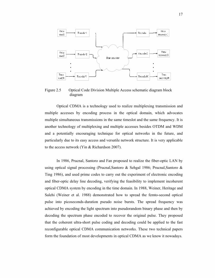
Figure 2.5 Optical Code Division Multiple Access schematic diagram block diagram
Optical CDMA is a technology used to realize multiplexing transmission and
multiple accesses by encoding process in the optical domain, which advocates
multiple simultaneous transmissions in the same timeslot and the same frequency. It is
another technology of multiplexing and multiple accesses besides OTDM and WDM
and a potentially encouraging technique for optical networks in the future, and
particularly due to its easy access and versatile network structure. It is very applicable
to the access network (Yin & Richardson 2007).
In 1986, Prucnal, Santoro and Fan proposed to realize the fiber-optic LAN by
using optical signal processing (Prucnal,Santoro & Sehgal 1986; Prucnal,Santoro &
Ting 1986), and used prime codes to carry out the experiment of electronic encoding
and fiber-optic delay line decoding, verifying the feasibility to implement incoherent
optical CDMA system by encoding in the time domain. In 1988, Weiner, Heritage and
Salehi (Weiner et al. 1988) demonstrated how to spread the femto-second optical
pulse into picoseconds-duration pseudo noise bursts. The spread frequency was
achieved by encoding the light spectrum into pseudorandom binary phase and then by
decoding the spectrum phase encoded to recover the original pulse. They proposed
that the coherent ultra-short pulse coding and decoding could be applied to the fast
reconfigurable optical CDMA communication networks. These two technical papers
form the foundation of most developments in optical CDMA as we know it nowadays.
18
2.3.1 Optical CDMA Fundamentals
In an optical CDMA network, the transmission signal over a fiber-optic channel is
formed by the superimposing of pseudorandom optical CDMA signals encoded from
multiple channels. The signal is broadcasted to each node (user) in the network and a
receiver in each node decodes the signal. If the decoder output in this receiver is an
autocorrelation, the node can detect the information sent to it from the aforementioned
pseudorandom signals. Otherwise, if the decoder output is a cross-correlation function
(no apparent peak value), then the node cannot receive the information (Yin &
Richardson 2007).
Therefore, in order to implement optical CDMA communication and
networking, address codes with sufficient performance are required. Whenever a set
of code specifications is preferred, a code can be constructed that has as many code
words (corresponding to the number of nodes in the network) as required with good
enough auto- and cross-correlation so that precise synchronization can be carried out
and the multiple access interference (MAI) from other users can be suppressed
effectively by decoding the signals. This requires that the address codes should satisfy
two conditions (Salehi 1989; Salehi & Brackett 1989): shifted versions can easily
produce all possible address code words and these shifted versions should be easily
distinguished from every other code words group. From the viewpoint of coding
theory, these address code words have to satisfy two main situations: (1) when the
cross correlation role between each codeword and any other codeword in the same set
of address code words is low, and (2) when each codeword in a set has a high
autocorrelation peak and low autocorrelation side lobes.
2.3.2 Optical CDMA System Characteristics
To implement entire optical CDMA communication systems in the optical domain,
there have been numerous researches and attempts to grasp the full advantages and
benefits of fiber optic signal processing techniques. Yin, and Richardson (2007)
presented these advantages as following:
19
a. Employing optical processing to accomplish particular network applications such
as addressing, directing and routing. Therefore, optical CDMA can perform high-
speed transmission, switching and add/drop of data by employing all-optical signal
processing, and consequently it can realize all-optical communication and all-
optical networking and overwhelm the effect of the electronic bottleneck that
exists in the electronic interchange in the conventional network.
b. Authorized users can access the network randomly with a high capability of data
throughput. Therefore, the optical CMDA networks have the soft capacity and the
pattern of networking is remarkably adaptable.
c. Optical CDMA has a low delay access that is appropriate to bursty local area
network traffic and doesn’t need buffering in a queue.
d. In optical CDMA systems the network topology, traffic and protocol are
transparent. They can support variable bit-rate traffic and bursty traffic and carry
out differential QoS according to demand with effective allocation of bandwidth
responding to the requirement. Optical CDMA networks can be easily improved
and extended due to the flexibility of the network architecture.
e. Optical CDMA networks need high speed coding and decoding process with fewer
devices than WDM networks. The implementing cost of optical CDMA networks
is low because of the asynchronous data transmission that simplifies network
planning, management and control. On the other hand, DWDM networks need
precise wavelength control and conversion. Moreover, optical CDMA is extremely
suitable with DWDM and TDM.
f. Optical CDMA networks are considered, to a certain extent, to be secure and
cryptic for the transmission of valuable information. Furthermore, these networks
employ distributed management, which is simple, and it is accessible to locate
network failure and secure and improve.
20
Because of the advantages mentioned above, optical CDMA can support
multimedia including voice, data, video, including IP traffic, video-on-demand,
streaming media, interactive applications, etc. And it also supports many types of QoS
and differential degrees of security fitting to different services and user’s
requirements. At the same time, it can overcome the defects of asymmetric uplink and
downlink in current access networks and supports FTTH of the peer-to-peer traffic
(Yin & Richardson 2007). Therefore, the advantages of asynchronous transmission
and the capability of multiple accesses in a bursty situation make optical CDMA
attractive for LAN applications.
2.3.3 Optical CDMA Systems Classifications
Many types of optical CDMA systems have been proposed as the result of intensive
research on optical CDMA in the past 20 years (Prucnal 2006; Yin & Richardson
2007).
If we classify them in terms of the nature of the superposition of the optical
signal, they can be divided into coherent optical CDMA systems and incoherent
optical CDMA systems as shown in Figure 2.6. The coherent optical CDMA system
makes use of the coherent property of light and implements bipolar encoding of the
optical signal, i.e., encoding the phase of optical signals, with the phase of light
detected at the receiving terminals. The form of signal addition is the superposition of
light signal amplitudes. This kind of optical CDMA system needs to use ultrashort
broadband light pulse sources (Jiang et al. 2005). The incoherent optical CDMA
system employs the presence of light signal or absence of light signal to represent the
binary “1” and “0” respectively, which is unipolar encoding, where the light signals
are detected with the square-law devices at the receiving terminals. This form of
signal addition is the superposition of light powers. This kind of optical CDMA
system may use incoherent light sources, such as amplified spontaneous emission
(ASE), light-emitting diode (LED), etc (Papannareddy & Weiner 1999; Zaccarin &
Kavehrad 1993).

21
If we categorize them depending on the differences of coding approaches for
optical signals, there are six kinds of optical CDMA systems (Yin & Richardson
2007):
a. direct-sequence or temporal encoding optical CDMA systems, also known as
spread-spectrum encoding optical CDMA systems;
b. spectral amplitude encoding Optical CDMA systems;
c. spectral phase encoding optical CDMA systems;
d. temporal phase encoding optical CDMA systems;
e. two-dimensional spatial encoding optical CDMA systems, also known as spread
space encoding;
f. Hybrid encoding optical CDMA systems. This kind of system uses a combination
of the encoding approaches mentioned above. We can acquire two-dimensional
encoding, for instance, wavelength-hopping/time-spread (WH/TS) encoding,
through using the combination of spectrum encoding with temporal encoding. If
space encoding is combined with WH/TS encoding again, space-spread/
wavelength hopping/ time-spreading encoding (SS/WH/TS) (Sangin et al. 2000)
can be obtained and the other options may be deduced by analogy.
Figure 2.6 Optical CDMA system classifications
22
If we categorize them depending on the amount of resources of time, wavelength,
space and polarization used, there are three kinds of optical CDMA systems. They can
be divided into one-dimensional systems, two-dimensional systems and three-
dimensional systems (Yin & Richardson 2007).
Since the mid-1980s, the encoding theory and encoding technology of optical
CDMA have been studied and developed thoroughly and many research
accomplishments have been made (Prucnal 2006). The encoding approaches of optical
CDMA can be divided into several categories based on the choice of different light
sources (e.g., coherent vs. incoherent, narrowband vs. broadband), different detection
schemes (e.g., coherent vs. incoherent), encoding approaches (e.g., time vs.
wavelength, amplitude vs. phase) and encoding dimensions, which are shown in
Figure 2.6.
2.4 TYPES OF OPTICAL CDMA CODES
Optical CDMA systems can generally be classified into two major types according to
the mechanism in which the optical signal is encoded and detected. Coherent optical
CDMA systems often use ultrashort wideband light pulse sources and manipulate the
phase of the signal field in the encoding and decoding processes. In contrast,
incoherent optical CDMA systems utilize incoherent light source and employ
amplitude-modulated code where the decoding of signal is based on the power
summation of optical pulses.
2.4.1 Coherent Optical CDMA Systems
In the coherent optical CDMA system, phase is important in its encoding/decoding
design and properties. In the transmitter part of the coherent optical CDMA system, a
specified user’s code is mostly applied via phase coding of the optical signal field,
which is generally obtained from a highly coherent wideband source, such as a mode-
locked laser. While in the receiver section, the coherent optical CDMA system
depends on a coherent restoration of the signal field to decode and recover the user’s
23
data. Advantages and disadvantages of the coherent optical CDMA schemes are
explained in Table 2.1.
Based on the way in which phase coding is applied to the optical signal field,
this category of coherent optical CDMA systems are classified to two possible types.
• Spectral Phase Coded Optical CDMA (SPC-optical CDMA)
• Temporal Phase Coded Optical CDMA (TPC-optical CDMA)
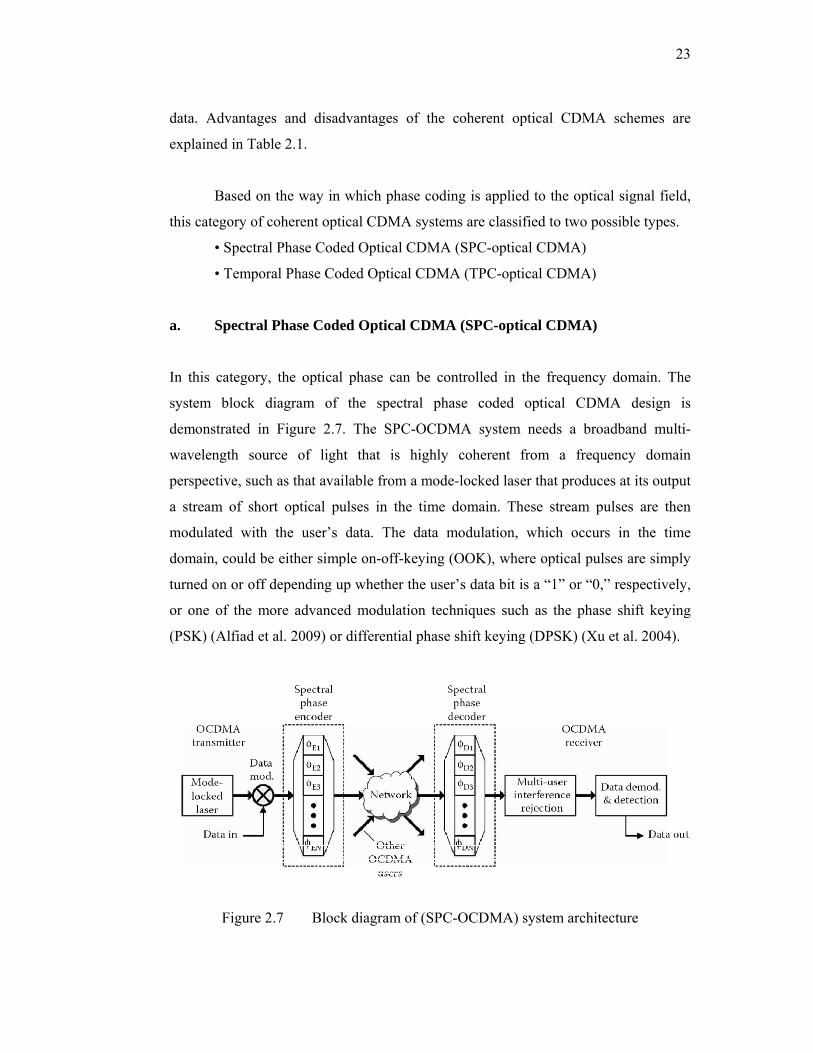
a. Spectral Phase Coded Optical CDMA (SPC-optical CDMA)
In this category, the optical phase can be controlled in the frequency domain. The
system block diagram of the spectral phase coded optical CDMA design is
demonstrated in Figure 2.7. The SPC-OCDMA system needs a broadband multi-
wavelength source of light that is highly coherent from a frequency domain
perspective, such as that available from a mode-locked laser that produces at its output
a stream of short optical pulses in the time domain. These stream pulses are then
modulated with the user’s data. The data modulation, which occurs in the time
domain, could be either simple on-off-keying (OOK), where optical pulses are simply
turned on or off depending up whether the user’s data bit is a “1” or “0,” respectively,
or one of the more advanced modulation techniques such as the phase shift keying
(PSK) (Alfiad et al. 2009) or differential phase shift keying (DPSK) (Xu et al. 2004).
Figure 2.7 Block diagram of (SPC-OCDMA) system architecture
24
Following data modulation, the modulated signal is inserted into a spectral
phase encoder, which assigns a specific optical CDMA phase code to the spectrum.
Each user is assigned one of a set of L components spectral phase codes. The spectral
phase encoders separate the modulated spectrum into spectral bins and assign a
different phase shift to each bin. The phase elements could be simple binary codes,
such as 0 or π, or more advanced multilevel phase. The encoded signal can be
passively combined or multiplexed with other optical CDMA signals by using an
optical combiner. Each of these combined signals will have its own unique spectral
phase code but intersection definitely in the frequency domain. At the receiver part, a spectral phase decoder is first employed to recover the
exact optical CDMA network user’s signal, which is approximately matching with the
spectral phase encoder placed at the transmitter, but it has a conjugate spectral phase
mask. After the decoding process, it is necessary to eliminate the multiuser
interference (MUI) noise that resulting from unwanted optical CDMA users. Then, the
wanted user’s data signal can be recovered through data demodulation and detection.
Based on the frequency resolution of each spectral phase component, spectral phase
coded optical CDMA systems can be classified into wideband SPC-optical CDMA
(referred to as ultrashort or femtosecond pulse optical CDMA) (Salehi et al. 1990;
Weiner et al. 1988) and narrowband SPC-optical CDMA (Shahab et al. 2004).
b. Temporal Phase Coded Optical CDMA (TPC-optical CDMA)
In this category, the optical phase can be controlled in the time domain and called the
temporal phase coded optical CDMA system as shown in Figure 2.8 (Sotobayashi et
al. 2001). For this scheme, it is simply required to consider the development of signal
waveforms in the time domain to realize its operation. Both the TPC-optical CDMA
and the SPC-optical CDMA have several similarities in terms of system architectures.
For example, the light source in the TPC-optical CDMA system is also frequently a
mode-locked laser. However, in this case, it is not the multi-wavelength spectral
characteristics of the mode-locked laser that are employed as was the case for SPC-
optical CDMA, but rather its short pulse capabilities. In addition to that, the same

25
modulation formats used for the SPC-optical CDMA can be employed for the TPC-
optical CDMA systems.
Figure 2.8 Block diagram of (TPC-optical CDMA) system architecture
Following modulation, a temporal phase encoder is used to produce L pulse
duplicates, each of which delayed hence that they lie on an equally separated time
grid. The spacing between pulses is described as the temporal chip interval. In
addition to the coarse time delay between pulse copies, there is also a fine relative
phase shift. Every encoded pulse is determined to a particular corresponding phase
shift based on the specific user’s allocated optical CDMA code. Similar to SPC-
optical CDMA methods, the individual phase elements could be built from simple
binary codes, such as 0 or π, or further advanced multilevel phase codes. The encoded
signal can be passively combined or multiplexed with other optical CDMA signals
into a single transmission medium, such as a common single-mode optical fiber. Each
of these combined signals will have its own unique temporal phase codes.
At the receiver section, a matched filtering process, which can be best
described as a time domain operation, is occupied to detect a specific TPC-OCDMA
user’s data stream. This temporal phase decoder is similar to the transmitter’s
temporal phase encoder, but set to the conjugate of the desired transmitter’s encoder.
Then, the elimination of the multiuser interference (MUI) noise that resulting from
26
unwanted optical CDMA users is required by using technologies, such as optical time
gating and optical thresholding. Then, the wanted user’s data signal can be recovered
through data demodulation and detection.
2.4.2 Incoherent Optical CDMA Systems
Despites the strengths of the coherent optical systems, the usage of these systems is
complicated, and they are very expensive as they require a phase control and laser
source which act as local oscillator at the optical frequency. Incoherent schemes use
the simpler, more standard techniques of intensity modulation with direct detection
while coherent schemes are based on the modulation and detection of optical phase
(Lam 2000). Advantages and disadvantages of incoherent optical CDMA schemes
explained in table 2.1.The most common approaches to incoherent optical CDMA are
based on, temporal (time) spreading, spatial coding, two-dimensional (2D)
wavelength-hopping time-spreading (WHTS), and spectral amplitude coding (SAC).
In this section, we will provide a brief overview of all these approaches and we will
focus, particularly, on spectral amplitude coding (SAC) that is under this transmission
security analysis.
Mostly, in incoherent optical CDMA systems that employ OOK modulation
format, each user is allocated with a specific code sequence: a coded transmission is
sent to represent a data bit 1, and a null is used to represent a bit 0. The signals are
unipolar because there are no negative signal components. Other modulation
techniques have been proposed to avoid loss of code confidentiality and increase
spectral efficiency. These schemes have been modified to assign two codes per user; a
1 being represented by a code and a 0 being represented by another (Hui 1985;
Narimanov et al. 2005; Shake, Thomas H. 2005).
a. Temporal Spreading
In the past, the temporal spreading scheme was considered to be one of the first
optical CDMA schemes that have already been implemented (Prucnal,Santoro & Ting
1986). In this scheme, each bit period is divided into TN smaller time intervals ( TN
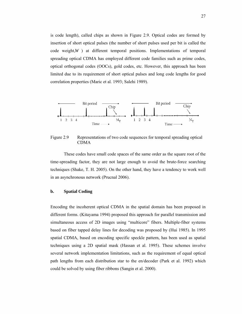
27
is code length), called chips as shown in Figure 2.9. Optical codes are formed by
insertion of short optical pulses (the number of short pulses used per bit is called the
code weight,W ) at different temporal positions. Implementations of temporal
spreading optical CDMA has employed different code families such as prime codes,
optical orthogonal codes (OOCs), gold codes, etc. However, this approach has been
limited due to its requirement of short optical pulses and long code lengths for good
correlation properties (Maric et al. 1993; Salehi 1989).
Figure 2.9 Representations of two code sequences for temporal spreading optical CDMA
These codes have small code spaces of the same order as the square root of the
time-spreading factor, they are not large enough to avoid the brute-force searching
techniques (Shake, T. H. 2005). On the other hand, they have a tendency to work well
in an asynchronous network (Prucnal 2006).
b. Spatial Coding
Encoding the incoherent optical CDMA in the spatial domain has been proposed in
different forms. (Kitayama 1994) proposed this approach for parallel transmission and
simultaneous access of 2D images using “multicore” fibers. Multiple-fiber systems
based on fiber tapped delay lines for decoding was proposed by (Hui 1985). In 1995
spatial CDMA, based on encoding specific speckle pattern, has been used as spatial
techniques using a 2D spatial mask (Hassan et al. 1995). These schemes involve
several network implementation limitations, such as the requirement of equal optical
path lengths from each distribution star to the en/decoder (Park et al. 1992) which
could be solved by using fiber ribbons (Sangin et al. 2000).
28
c. Two-Dimensional (2D) Wavelength-Hopping Time-Spreading (WH-TS)
Wavelength-hopping time-spreading (WHTS) system is a two-dimensional (2D)
coding approach that spreads the codes in both the wavelength and time domains at
the same time (Tancevski et al. 1994), achieving increased code design flexibility as
well as code performance. Zero autocorrelation side-lobes can be obtained with low
cross correlations and higher cardinality at reduced code lengths.
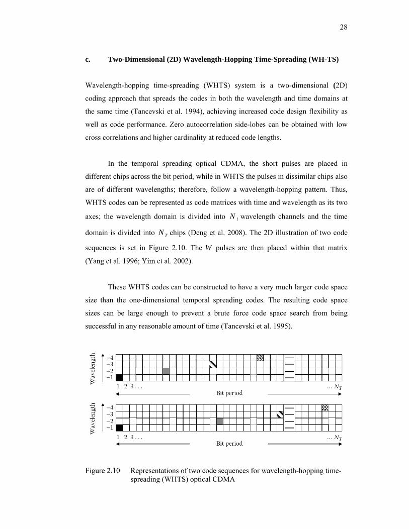
In the temporal spreading optical CDMA, the short pulses are placed in
different chips across the bit period, while in WHTS the pulses in dissimilar chips also
are of different wavelengths; therefore, follow a wavelength-hopping pattern. Thus,
WHTS codes can be represented as code matrices with time and wavelength as its two
axes; the wavelength domain is divided into lN wavelength channels and the time
domain is divided into TN chips (Deng et al. 2008). The 2D illustration of two code
sequences is set in Figure 2.10. The W pulses are then placed within that matrix
(Yang et al. 1996; Yim et al. 2002).
These WHTS codes can be constructed to have a very much larger code space
size than the one-dimensional temporal spreading codes. The resulting code space
sizes can be large enough to prevent a brute force code space search from being
successful in any reasonable amount of time (Tancevski et al. 1995).
Figure 2.10 Representations of two code sequences for wavelength-hopping time- spreading (WHTS) optical CDMA

29
Figure 2.11 shows the general schematic of a WHTS optical CDMA network.
Each user may assign with a code sequence corresponding to the constructed WHTS
code matrices. It is obvious from Figure 2.11 that both the transmitter and receiver
have two main elements. The transmitter consists of the source and the encoder while
the receiver consists of the decoder and the receiver electronics. Subsystems for
reducing interference from other users can be optionally built into the receiver. In
addition to that, WHTS is an incoherent scheme where the transmission of a user’s
data signal is modulated with OOK modulation format (Baby et al. 2005 ; Tancevski
& Andonovic 1994).
Figure 2.11 Schematic block diagram of a WHTS optical CDMA network
In the transmitter part, several optical sources may be employed, ranging from
an array of lasers each operating at a fixed wavelength to spectrally slicing a
broadband source generated by a super-continuum (Baby et al. 2005 ). As shown in
Figure 2.11, the encoding of the modulated signal takes place at the WHTS encoder
whereby the signal is passed through a filter such as arrayed waveguide gratings or
thin film filters that separates each lN wavelength components into different
channels according to their central wavelengths(Kwong et al. 2005). Each wavelength
is individually delayed relative to each other according to a specific code. The
resulting signal is then combined and transmitted to the network (Deng et al. 2008).
At the receiver end, the received signal, which includes signals from all users
on the network, is decoded by a matched decoder, which is similar to the setup of the

30
encoder but incorporates the complementary set of delay lines. When the user’s code
matches with a sequence of time chips, the encoded wavelengths are de-spread into
the same timeslot producing an autocorrelation peak while the chip patterns of other
users appear as low intensity multiple access interference (MAI). The MAI noise
contributed from other users’ transmission can be removed by using optical time
gating systems such as a terahertz optical asymmetric demultiplexer (TOAD)
(Sokoloff et al. 1993), which has been used for both all-optical gating and
thresholding to extract the desired autocorrelation peak.
d. Spectral Amplitude Coding (SAC)
Spectral amplitude coding (SAC), which was first anticipated by Zaccarin and
Kavehrad (Kavehrad & Zaccarin 1995), is carried out by spectrally decomposing a
broadband light source followed by an optical component that can modulate the
intensity of the different spectral components before again merging them. Both grating
elements with spatial amplitude masks as illustrated in Figure 2.12, (Zaccarin &
Kavehrad 1993). For blocking or passing these different spectral components, filters
with periodic spectral transfer functions have been used (Pfeiffer et al. 1999). Typical
broadband sources used include light emitting diodes (LEDs), superluminescence
diodes (SLDs) and erbium doped fiber sources. Demonstrations have shown the
capability to provide high speed (155 Mb/sec) access network connections without
wavelength stabilization and spectral control (Pfeiffer et al. 1999).
Figure 2.12 Spectral amplitude coding (SAC) using diffraction gratings and spatial masks
31
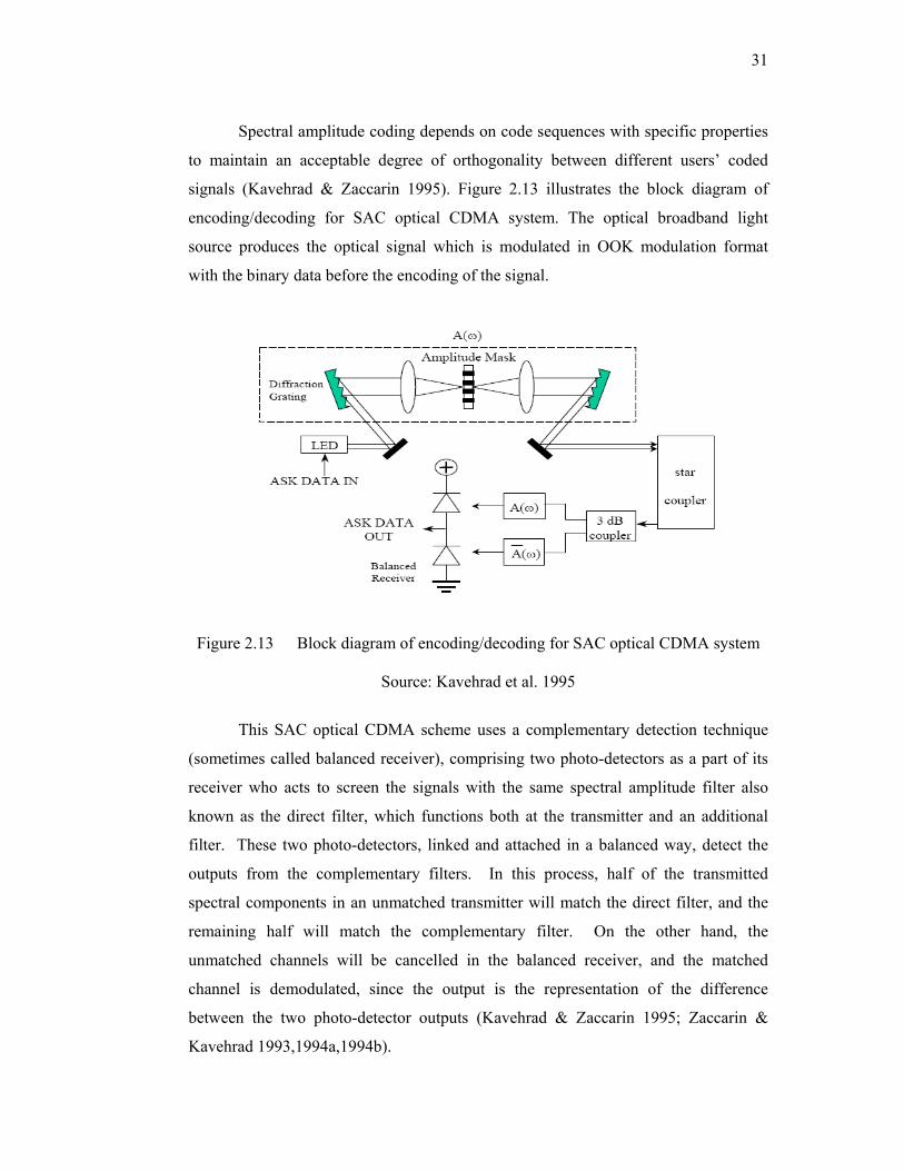
Spectral amplitude coding depends on code sequences with specific properties
to maintain an acceptable degree of orthogonality between different users’ coded
signals (Kavehrad & Zaccarin 1995). Figure 2.13 illustrates the block diagram of
encoding/decoding for SAC optical CDMA system. The optical broadband light
source produces the optical signal which is modulated in OOK modulation format
with the binary data before the encoding of the signal.
Figure 2.13 Block diagram of encoding/decoding for SAC optical CDMA system
Source: Kavehrad et al. 1995
This SAC optical CDMA scheme uses a complementary detection technique
(sometimes called balanced receiver), comprising two photo-detectors as a part of its
receiver who acts to screen the signals with the same spectral amplitude filter also
known as the direct filter, which functions both at the transmitter and an additional
filter. These two photo-detectors, linked and attached in a balanced way, detect the
outputs from the complementary filters. In this process, half of the transmitted
spectral components in an unmatched transmitter will match the direct filter, and the
remaining half will match the complementary filter. On the other hand, the
unmatched channels will be cancelled in the balanced receiver, and the matched
channel is demodulated, since the output is the representation of the difference
between the two photo-detector outputs (Kavehrad & Zaccarin 1995; Zaccarin &
Kavehrad 1993,1994a,1994b).

32
Table 2.1 Advantages and disadvantages of the coherent and incoherent optical CDMA schemes
Optical CDMA Schemes
Advantages Disadvantages
Coherent optical CDMA
a. Allows the manipulation of the optical field it could provide better suppression of multi-access interference
b. Mode-locked lasers are expected to allow better system performance than LED
c. Using spectral phase coding of coherent, ultrashort pulses predicted that throughput could in principle exceed 100 Gb/s
d. Longer code lengths offers a significant throughput advantage and a fundamentally better scaling behavior with the number of users
e. Requires advanced femtosecond technology, therefore it is still a research challenge.
a. Due to coherence multiplexing, the system performance degrades if more users are needed.
b. Environmental influence and the polarization drift, rendering the coherent approach difficult to implement
c. The beat noise is the dominant noise source and main limit on system performance.
d. The mode-locked laser needs to operate at twice the data modulation rate
Incoherent optical CDMA
a. Fewer stability requirements for optical encoder/decoders
b. Need only sources with a small coherence time
c. The use of LED may reduce the cost of system significantly
d. The use of coherence multiplexing and spectral amplitude coding, offer a simpler technology
e. Free of beat noise
a. The correlation is based on optical power summation
b. Usually support fewer simultaneous active users, which is severely limited by the size of the code set
c. Incoherent light source might suffer from optical beat noise
d. Limited to throughputs of 10-50 Gb/s
e. PIIN and MAI are the dominant noise source
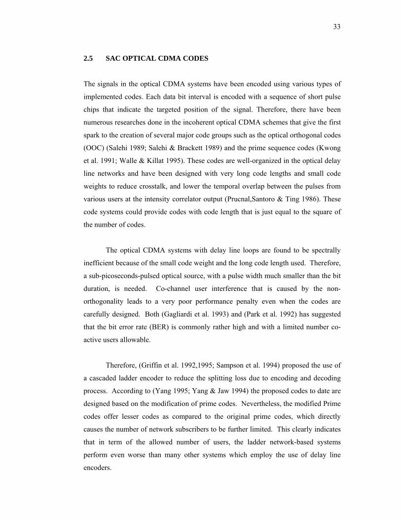
33
2.5 SAC OPTICAL CDMA CODES
The signals in the optical CDMA systems have been encoded using various types of
implemented codes. Each data bit interval is encoded with a sequence of short pulse
chips that indicate the targeted position of the signal. Therefore, there have been
numerous researches done in the incoherent optical CDMA schemes that give the first
spark to the creation of several major code groups such as the optical orthogonal codes
(OOC) (Salehi 1989; Salehi & Brackett 1989) and the prime sequence codes (Kwong
et al. 1991; Walle & Killat 1995). These codes are well-organized in the optical delay
line networks and have been designed with very long code lengths and small code
weights to reduce crosstalk, and lower the temporal overlap between the pulses from
various users at the intensity correlator output (Prucnal,Santoro & Ting 1986). These
code systems could provide codes with code length that is just equal to the square of
the number of codes.
The optical CDMA systems with delay line loops are found to be spectrally
inefficient because of the small code weight and the long code length used. Therefore,
a sub-picoseconds-pulsed optical source, with a pulse width much smaller than the bit
duration, is needed. Co-channel user interference that is caused by the non-
orthogonality leads to a very poor performance penalty even when the codes are
carefully designed. Both (Gagliardi et al. 1993) and (Park et al. 1992) has suggested
that the bit error rate (BER) is commonly rather high and with a limited number co-
active users allowable.
Therefore, (Griffin et al. 1992,1995; Sampson et al. 1994) proposed the use of
a cascaded ladder encoder to reduce the splitting loss due to encoding and decoding
process. According to (Yang 1995; Yang & Jaw 1994) the proposed codes to date are
designed based on the modification of prime codes. Nevertheless, the modified Prime
codes offer lesser codes as compared to the original prime codes, which directly
causes the number of network subscribers to be further limited. This clearly indicates
that in term of the allowed number of users, the ladder network-based systems
perform even worse than many other systems which employ the use of delay line
encoders.
34
(Meghavoryan & Baghdasaryan 2001) has stated that the Hadamard codes are
more suitable to be used because the density of “1”s and “0”s is more homogeneous,
while at the same time, every user has almost the same average power. (Lam et al.
1998) has revealed that one of the disadvantages of these codes is that they do not
support many channels in a single transmission. In addition to that, (Aljunid et al.
2004) stated that the bit error rate is rather high and that only two co-active users are
allowed at a time.
From the above brief review, it can be deduced that these codes have different
limitations in many ways. Among these limitations, the construction of the codes are
either complicated as in the OOC and modified frequency hopping (MFH) codes (Zou
& Ghafouri-Shiraz 2002a,2002c), the cross-correlation are not ideal, as in the
Hadamard and prime codes (Holmes & Syms 1992), or the length of the code length is
too long as in the OOC and prime codes. Due to the preference and requirement for
either very wide band sources or very narrow filter bandwidths, long code lengths are
regarded as a drawback in its implementation.
To overcome the previous mentioned limitations, many researchers have
proposed new code families and modified versions of the old SAC optical CDMA
codes. Therefore, many codes have been proposed and applied to be used for
incoherent optical CDMA networks implementations. New sequence code families
such as modified prime code (PMR) (Kwong et al. 1991), modified congruence code
(MQC) (Wei et al. 2001), modified frequency hopping (MFH) (Zou & Ghafouri-
Shiraz 2002a,2002c), Hadamard code, and maximal length sequences (m-sequences)
(Peterson et al. 1995) have been proposed, of which their performance is analyzed
based on the number of users and bit error rate (BER) (Smith et al. 1998; Wei et al.
2001). Other new code families based on a mapping technique, such as double weight
(DW), modified double weight (MDW) (Aljunid et al. 2004) and enhanced double
weight (EDW) (Hasoon et al. 2007) have been proposed and implemented. It has been
shown that these codes have much better performance in comparison with Hadamard
and MFH codes (Abdullah et al. 2008; Aljunid et al. 2004).

35
Optical CDMA technology has obvious superiority for constructing the local
area networks (LANs) and access networks in contrast to other multiplexing
techniques. The need for transmission security in the developing of optical CDMA
networks at the physical layer is becoming increasingly important. Spectral amplitude
coding (SAC) is an encoding approach to implement optical CDMA networks.
Although the system performance of SAC optical CDMA has been presented by many
researchers, its security show has not presented widely. Therefore, there is a need to
investigate the transmission security that can be provided by SAC optical CDMA.
Therefore, this section includes a discussion of some codes of the SAC optical CDMA
systems.
2.5.1 Optical Orthogonal Codes
In 1989, the optical orthogonal codes have been introduced by (Salehi et al. 1989) and
(Chung et al. 1989) as a way to acquire simultaneous transmissions amongst
asynchronous users in incoherent optical CDMA systems. These codes, which have
the notation of codeword C ( , , , )a cn w λ λ is a set of (0, 1) sequences of length n and
weight w, the weight is referred to as the number of “1”s in the codeword (number of
wavelengths). The fact that the auto correlation side lobes lesser than the auto
correlation aλ , and the cross correlation is lesser than cross correlation constrain cλ , is
satisfying. In addition, the auto correlation function peak is w due to the fact that the
weight of the individual code in the optical orthogonal codes is w. The size of the
OOC which is also called the cardinality of the OOC is the sequence number or the
codeword in the family denoted by C . The code is therefore defined as ),,( λwn
when the correlation constrains are the same, i.e., ca λλ = .
Due to the fact that the number of codes represent the number of users in the
OCDMA network, it is desirable to have the biggest possible size of an OOC for a
given set of values for ),,,( cawn λλ . The optimal OOC refers to the OOC with the
maximum possible size. According to Chung et al. (1989), for )1,1,,( wn , the
maximum size of the OOC is given from the algebraic coding theory by

36
[ ])1(/)1( −− wwn ; of which n is odd, and [ ])1(/)2( −− wwn if n is even.
The construction of the optical orthogonal can be done in three distinguished
ways. First, an iterative method with the use of an existing code; second, the OOC
using a “greedy” algorithm that is useful in various computational problems, is
constructed; and third, the use of the cross correlation and auto correlation properties
of the OOC is better than the earlier codes as they are constructed in order to produce
lesser correlation constrains. In spite of this, the construction of these codes is not an
easy process as they are very long. Hence, the correlation constrains can be relaxed to
a value of two in order to shorten the code length (Maric 1993; Maric et al. 1995;
Maric et al. 1993). However, the construction of the codes remains a very challenging
process.
2.5.2 Prime Codes
These codes are the orthogonal codes of length 2P derived from the prime sequences
of the length P obtained from the Galois field ( )GF P , where P is the prime number
(Holmes et al. 1992; Yang et al. 1995). They are developed as follows: using the
{ }( ) 0,1, 2, , , 1GF P j p= −K K , a prime sequence { }1 ( 1), , , , ,x xo x xj x PS s s s s −= K K is
derived from ( )GF P by multiplying every element j of ( )GF P by an element x of
( )GF P modulo-P. The P prime sequences can therefore be achieved. In addition,
these sequences are later mapped into a sequence of binary code
{ }21 1, , ,c xo x xP
C c c c−
= K by putting ones in the positions of , 0,1, , 1xjs jP j P+ = −K ,
and zeros in the rest of the places.
Due to the fact that the number of coincidences of one’s is at the most two, the
maximum cross correlation of the prime code is bounded to two. Nevertheless, the
auto correlation function side lobes do not exceed one, but the auto correlation
function peak is equal to the prime number P.

37
2.5.3 Hadamard Code
(Zou & Ghafouri-Shiraz 2002a,2002b; Zou,Ghafouri-Shiraz et al. 2001; Zou,Shalaby
et al. 2001) that the Hadamard codes can be used in various ways in digital signal
processing and Code Division Multiple Access (CDMA) communication systems. In
these codes, a Z-element Hadamard code is a row from the ZxZorthogonal Hadamard
matrix, consisting of (1,-1) valued binary entries. The ZxZHadamard matrix HM
where Z 2M= is generated by the core matrix, such as the following:
1 1H 1 1 1M
⎡ ⎤= ⎢ ⎥= −⎣ ⎦
(2.1)
For M=2, the Hadamard matrix is generated as below:
1 1 1 1H H 1 1 1 11 1H2 1 1 1 1H H11
1 1 1 1
⎡ ⎤⎢ ⎥⎡ ⎤ − −⎢ ⎥⎢ ⎥= =⎢ ⎥− −⎢ ⎥⎣ ⎦ ⎢ ⎥− −⎣ ⎦
(2.2)
Unipolar Hadamard matrix MH has the following properties:
a. M should be greater than 2
b. Code length N = M2
c. Code Weight W = 12 −M
d. User K= 12 −M (The case K= 1 has been excluded as the row of the
unipolar Hadamard matrix is all ones
e. The ratio of 2Wλ
= (i.e., λ is cross-correlation properties)
The fact that an ( ZxZ) Hadamard matrix of 1’s and –1’s reveal that it has the
property that any row differs from any other rows in exactly Z/2 positions. Therefore,
all the rows except for one contains Z/2 (-1)’s and Z/2 (1)’s, usually in the wavelength

38
domain where the –1 can be replaced with 0. Thus, the sequence (1, 0) is a unipolar
Hadamard code, as in Z= 4.
4
1 1 1 11 0 1 0
H1 1 0 01 0 0 1
⎡ ⎤⎢ ⎥⎢ ⎥=⎢ ⎥⎢ ⎥⎣ ⎦
(2.3)
The Hadamard code is capable of supporting 12 −M number of users. For
instance, if only 20 users are required, M has to be at least equivalent to 5 in order to
support up to 31 users, rendering 11 codes to be unused. This explains that the
Hadamard code is an inefficient code as the construction of the sequence cannot be
done according to the exact number of users, i.e., the Hadamard code has an
increasing value of cross-correlation when the number of users increases. Similarly,
this code also requires more number of filters for every code when the number of
users increases.
2.5.4 Modified Quadratic Congruence Code (MQC)
Modified quadratic congruence (MQC) code is a SAC incoherent optical CDMA that
defined by an odd prime number p. The establishment of MQC code was proposed by
Z. Wei et al in (Wei et al. 2001). According to (Wei et al. 2001), MQC code families
can be constructed in two steps as following:
a. Step 1:
Let ( )GF P represents a finite field of p elements. A number sequence ,
( )y kα β
is
assembled with elements of ( )GF P over an odd prime by using the following
expression:
{ 2
,
[( ) ](mod ), 0,1,..., 1[ ](mod ),( ) d k p k p
b p k py kα β
α βα
+ + = −+ ==
(2.4)
where { }d 0, 1, 2, , p 1∈ … − and { }b, , 0, 1, 2, , p 1α β ∈ … − .
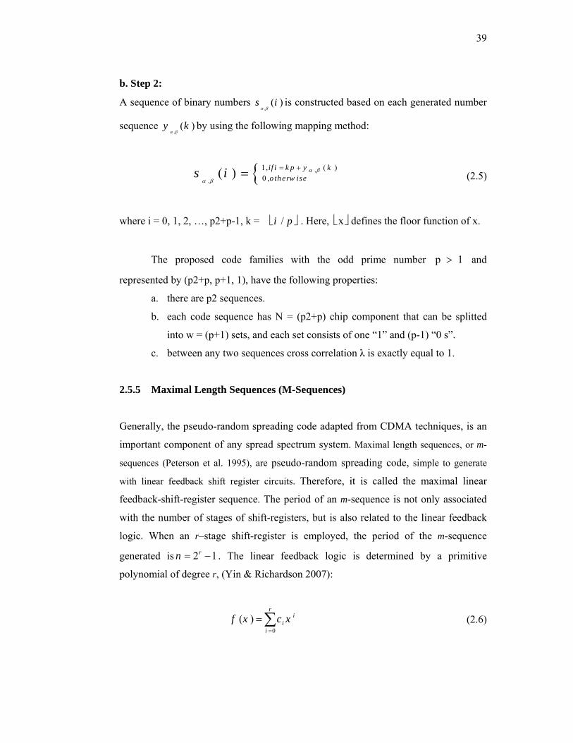
39
b. Step 2:
A sequence of binary numbers ,
( )s iα β
is constructed based on each generated number
sequence ,
( )y kα β
by using the following mapping method:
{ ,
,
1, ( )0 ,( ) if i k p y k
o th erw ises i α β
α β
= += (2.5)
where i = 0, 1, 2, …, p2+p-1, k = /i p ⎣ ⎦ . Here, x⎣ ⎦ defines the floor function of x.
The proposed code families with the odd prime number p 1> and
represented by (p2+p, p+1, 1), have the following properties:
a. there are p2 sequences.
b. each code sequence has N = (p2+p) chip component that can be splitted
into w = (p+1) sets, and each set consists of one “1” and (p-1) “0 s”.
c. between any two sequences cross correlation λ is exactly equal to 1.
2.5.5 Maximal Length Sequences (M-Sequences)
Generally, the pseudo-random spreading code adapted from CDMA techniques, is an
important component of any spread spectrum system. Maximal length sequences, or m-
sequences (Peterson et al. 1995), are pseudo-random spreading code, simple to generate
with linear feedback shift register circuits. Therefore, it is called the maximal linear
feedback-shift-register sequence. The period of an m-sequence is not only associated
with the number of stages of shift-registers, but is also related to the linear feedback
logic. When an r–stage shift-register is employed, the period of the m-sequence
generated is 2 1rn = − . The linear feedback logic is determined by a primitive
polynomial of degree r, (Yin & Richardson 2007):
0
( )r
ii
i
f x c x=
= ∑ (2.6)

40
The m-sequences schemes have the following many properties (Ziemer 2007):
a. An m-sequence contains one more 1 than 0.
b. The modulo-2 sum of an m-sequence and any phase shift of the same m-
sequence is another phase of the same m-sequence (a phase of the sequence
is a cyclic shift).
c. If a window of width r is slid along an m-sequence for N shifts, each r -
tuple except the all-zeros r - tuple will appear exactly once.
d. Define a run as a subsequence of identical symbols within the m-sequence.
Then, for any m-sequence, there are
• One run of ones of length r.
• One run of zeros of length r– 1.
• One run of ones and one run of zeros of length r– 2.
• Two runs of ones and two runs of zeros of length r– 3.
• Four runs of ones and four runs of zeros of length r– 4.
• . . .
• 2r−3 runs of ones and 2r–3 runs of zeros of length 1.
Therefore, due to the simplicity of these codes generation they are relatively
easy to intercept and regenerate by an eavesdropper receiver. The four stage maximal
length linear feedback shift register is shown in Figure 2.14 (Yin & Richardson 2007).
Suppose that the initial state of the shift-register is 1000. Then, under the action of
shift-clock, after 42 1n = − =15 clock times the shift-register can produce the maximal
length linear shift-register sequence with the period of 15 at its output,
111101011001000 (Yin & Richardson 2007).
Figure 2.14 Four stage maximal length linear feedback shift-register

41
Although m-sequences have ideal the autocorrelation property, it is difficult to
find a general method to predict their cross-correlation functions. It has been shown
by investigation that only very small sets of m-sequences can have good cross-
correlation properties and large sets of m-sequences generally have quite poor cross-
correlation properties (Dixon 1976). In (Chao-Chin et al. 2004), an arrayed waveguide
grating (AWG) router-based optical network codec pair propose has been proposed to
implement SAC optical CDMA network(Chao-Chin et al. 2004).
2.5.6 Double Weight (DW) Codes
These codes have been inspired from Hadamard codes that can be represented by the
this notation ( , , )cN W λ , where is the code length of the code sequence, W is code
weight and cλ represents the maximum cross correlation value between any two code
sequences. According to (Aljunid et al. 2004), the DW code can be constructed using
the following steps:
a. Step 1:
The DW code can be represented by using a K x N matrix notation. In DW code
structure, the matrix K rows and N columns represent the number of users and the
minimum code length respectively. A basic DW code is given by a 2 x 3 matrix, as
shown below:
(2.7)
Notice that HM=1 has a chips combination sequence of 1, 2, 1 for the three
columns. Sequence combination chips are defined by the summation of the values of
the corresponding elements in every two rows (i.e. 0+1, 1+1, 1+0). The purpose of 1,
2, 1 combination is to maintain the cross correlation value of one; only one overlap
between two chips will be allowed.
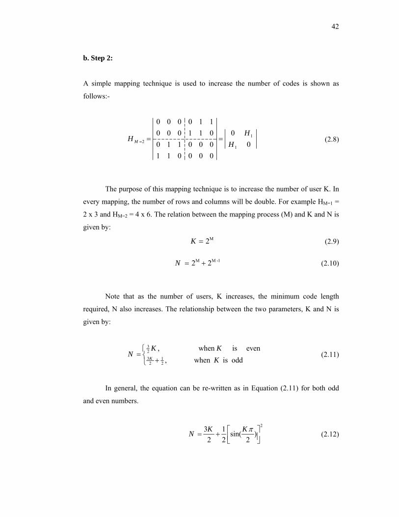
42
b. Step 2:
A simple mapping technique is used to increase the number of codes is shown as
follows:-
12
1
0 0 0 0 1 100 0 0 1 1 0
00 1 1 0 0 01 1 0 0 0 0
M
HH
H= = = (2.8)
The purpose of this mapping technique is to increase the number of user K. In
every mapping, the number of rows and columns will be double. For example HM=1 =
2 x 3 and HM=2 = 4 x 6. The relation between the mapping process (M) and K and N is
given by:
M2K = (2.9)
M M -12 2N = + (2.10)
Note that as the number of users, K increases, the minimum code length
required, N also increases. The relationship between the two parameters, K and N is
given by:
323 12 2
, when is even, when is oddK
K KN
K⎧
= ⎨+⎩
(2.11)
In general, the equation can be re-written as in Equation (2.11) for both odd
and even numbers.
23 1 sin( )
2 2 2K KN π⎡ ⎤= + ⎢ ⎥⎣ ⎦
(2.12)
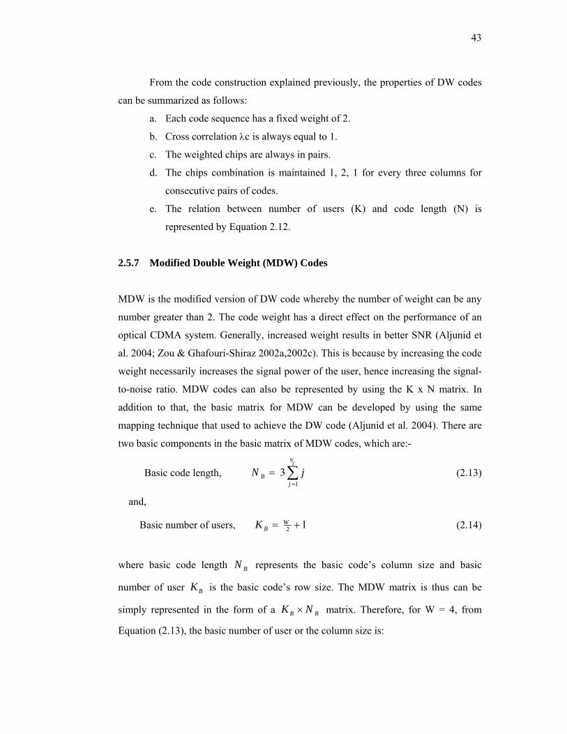
43
From the code construction explained previously, the properties of DW codes
can be summarized as follows:
a. Each code sequence has a fixed weight of 2.
b. Cross correlation λc is always equal to 1.
c. The weighted chips are always in pairs.
d. The chips combination is maintained 1, 2, 1 for every three columns for
consecutive pairs of codes.
e. The relation between number of users (K) and code length (N) is
represented by Equation 2.12.
2.5.7 Modified Double Weight (MDW) Codes
MDW is the modified version of DW code whereby the number of weight can be any
number greater than 2. The code weight has a direct effect on the performance of an
optical CDMA system. Generally, increased weight results in better SNR (Aljunid et
al. 2004; Zou & Ghafouri-Shiraz 2002a,2002c). This is because by increasing the code
weight necessarily increases the signal power of the user, hence increasing the signal-
to-noise ratio. MDW codes can also be represented by using the K x N matrix. In
addition to that, the basic matrix for MDW can be developed by using the same
mapping technique that used to achieve the DW code (Aljunid et al. 2004). There are
two basic components in the basic matrix of MDW codes, which are:-
Basic code length, 2
1
3W
Bj
N j=
= ∑ (2.13)
and,
Basic number of users, 2 1WBK = + (2.14)
where basic code length BN represents the basic code’s column size and basic
number of user BK is the basic code’s row size. The MDW matrix is thus can be
simply represented in the form of a B BK N× matrix. Therefore, for W = 4, from
Equation (2.13), the basic number of user or the column size is:
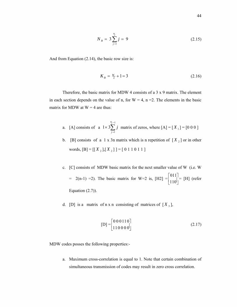
44
2
1
3 9W
Bj
N j=
= =∑ (2.15)
And from Equation (2.14), the basic row size is:
2 1 3WBK = + = (2.16)
Therefore, the basic matrix for MDW 4 consists of a 3 x 9 matrix. The element
in each section depends on the value of n, for W = 4, n =2. The elements in the basic
matrix for MDW at W = 4 are thus:
a. [A] consists of a 2 1
1
1 3W
j
j−
=
× ∑ matrix of zeros, where [A] = [ 1X ] = [0 0 0 ]
b. [B] consists of a 1 x 3n matrix which is n repetition of [ 2X ] or in other
words, [B] = [[ 2X ],[ 2X ] ] = [ 0 1 1 0 1 1 ]
c. [C] consists of MDW basic matrix for the next smaller value of W (i.e. W
= 2(n-1) =2). The basic matrix for W=2 is, [H2] =011110
⎡ ⎤⎢ ⎥⎣ ⎦
= [H] (refer
Equation (2.7)).
d. [D] is a matrix of n x n consisting of matrices of [ 3X ],
[D] =0 0 011 0110 0 0 0
⎡ ⎤⎢ ⎥⎣ ⎦
(2.17)
MDW codes posses the following properties:-
a. Maximum cross-correlation is equal to 1. Note that certain combination of
simultaneous transmission of codes may result in zero cross correlation.

45
b. MDW code weight can be any even number that is greater than 2 (multiple
of 2).
c. The weight-pair structure is maintained.
d. The chips combination is maintained 1, 2, 1 for every three columns for
every consecutive pairs of codes.
e. The relation between the Number of users (K) and code length (N) at
weight of 4 is given by :
283 sin( )
3 3KN K π⎡ ⎤= + ⎢ ⎥⎣ ⎦
(2.18)
The basic MDW code denoted by (9, 4, 1) or alternatively [H4] is therefore given by:
[H4] =
(2.19)
2.5.8 Enhanced Double Weight (EDW) Codes
EDW is an enhanced version of DW, whereby the number of weight can be any odd
number greater than one, as opposed to even weights in the latter (Hasoon et al. 2007).
The EDW code can be represented using a K N× matrix. In an EDW code structure,
the matrix K rows and N columns represent the number of users and the minimum
code length, respectively. In addition to that, the basic matrix for EDW can be
developed by using the same mapping technique that used to achieve both the DW and
MDW codes (Aljunid et al. 2004).
The basic matrix for the EDW codes also consists of a K N× matrix,
depending on the value of the code weight. The general form of the basic matrix of an
EDW code with weight, W is shown in Equation 2.20; where all the component
0 0 0 0 1 1 0 1 10 1 1 0 0 0 1 1 01 1 0 1 1 0 0 0 0
A B
C D

46
matrices [A1], [A2], and [Aw] depend on W.
[H] = 1 2 wA A A
⎡ ⎤⎢ ⎥⎢ ⎥⎢ ⎥⎢ ⎥⎢ ⎥⎢ ⎥⎣ ⎦
M M M
M M M
M M K M
M M M
M M M
(2.20)
In Equation 2.20, the elements in each section are defined as:
a. The number of element matrices Ne: [A1], [A2], ….., and [Aw] depend on
W.(i.e. if W=5, so the number of matrices is 5).
eN W= (2.21)
b. The size of each matrix consist of a aK N×
where,
aK W= (2.22)
1
w
ja
jN
W==
∑ (2.23)
c. Each matrix has a combination sequence of 1, 2, 2,……, 2 for the columns.
The combination sequence is depended on W and the number of resultant
2, 2rN is given by:
21
2rWN −
= (2.24)
(i.e. if W=5, so the combination sequence is 2,2,1)
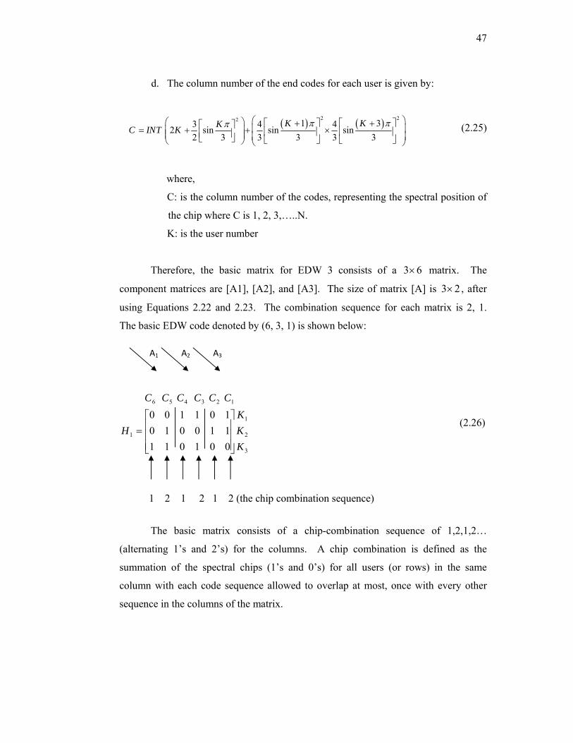
47
d. The column number of the end codes for each user is given by:
( ) ( )2 22 1 33 4 42 sin sin sin2 3 3 3 3 3
K KKC INT Kπ ππ ⎛ ⎞⎛ ⎞ + +⎡ ⎤ ⎡ ⎤⎡ ⎤ ⎜ ⎟= + + ×⎜ ⎟ ⎢ ⎥ ⎢ ⎥⎢ ⎥⎜ ⎟ ⎜ ⎟⎣ ⎦ ⎣ ⎦ ⎣ ⎦⎝ ⎠ ⎝ ⎠
(2.25)
where,
C: is the column number of the codes, representing the spectral position of
the chip where C is 1, 2, 3,…..N.
K: is the user number
Therefore, the basic matrix for EDW 3 consists of a 3 6× matrix. The
component matrices are [A1], [A2], and [A3]. The size of matrix [A] is 3 2× , after
using Equations 2.22 and 2.23. The combination sequence for each matrix is 2, 1.
The basic EDW code denoted by (6, 3, 1) is shown below:
3
2
1
1
123456
001011110010101100
KKK
H
CCCCCC
⎥⎥⎥
⎦
⎤
⎢⎢⎢
⎣
⎡=
(2.26)
The basic matrix consists of a chip-combination sequence of 1,2,1,2…
(alternating 1’s and 2’s) for the columns. A chip combination is defined as the
summation of the spectral chips (1’s and 0’s) for all users (or rows) in the same
column with each code sequence allowed to overlap at most, once with every other
sequence in the columns of the matrix.
A3 A2 A1
1 2 1 2 1 2 (the chip combination sequence)

48
2.6 OVERVIEW OF THE VULNERABILITIES IN OPTICAL COMMUNICATION NETWORKS
Even though fiber optical cables are exponentially more secure than standard wiring
or wireless medium communications systems, there are still ways that adversaries can
tap into and intercept confidential information that travelling across optical networks
(Shaneman & Gray 2004). In other words, fiber optical cable is just vulnerable to
simple technical attacks.
Usually, interceptors to networks frequently count on finding a single weak
link in the optical network structural design which will then allow them access to the
rest of the network. Network security measures must account for this, as well as other
complexities, in an attempt to maintain the security of the network information and
resources (Fisch & White 2000).
Being optical communications, its network security should be still designed to
meet the security objectives of providing confidentiality, availability, integrity and
usage for authorized users of the network resources. Nowadays, optical
communications are important issues in modern information technology and service
based economies such as global commerce which is dependent upon the significant
communications infrastructure and relies on the above mentioned security objectives
(Oyster Optics 2008).
Unfortunately, the entire private and public network suppliers and their
respective customers are absolutely susceptible and vulnerable to one or more of
security threats resulting into tapping and stealing of their significant communications
and information. When optical networks are considered in the local and access loops,
their security transmissions are vulnerable for attacks where eavesdroppers have
sufficient opportunity to access fiber. In the local and access loops speeds and network
topology are relatively simple to control, therefore equipments required, by
eavesdropper, for optical tapping are less expensive and simple.
Compared with incoherent optical CDMA systems, coherent optical CDMA
systems often have the advantage of lower MUI due to the possibility of a destructive
interference at the receiver (Hernandez et al. 2007). The following chapters will focus

49
on security performance that is related to the spectral amplitude coding optical CDMA
systems. Table 2.2 illustrates the properties of several SAC optical CDMA systems,
which are required to investigate the transmission security. For each particular code
we have considered the number of users (K), code length (N), code weight (W), and
signal to noise ratio (SNR). Since the intensity noise dominates in the SAC optical
CDMA systems, and increasing the received optical power cannot alleviate its effect,
the signal to noise ratio (SNR) limit due to this noise is considered in table 2.2.
Table 2.2 Properties of several SAC optical CDMA systems
SAC Code Existence
Number of users
(K)
Code Length
(N)
Weight
(W)
Cross correlation
( λ ) PIINSNR
M-sequenec r 2 1r − 2 1r −
1
2N +
1
4N +
[( 1) ]
{ ( 1)}N
NBK Kυ+ Δ+
EDW n nK =
Refer to Equation
(2.25)
3=W 1=λ
22( 1)
[(2 4) ]W
BKW K Wυ− Δ
− +
MDW n nK =
Refer to Equation
(2.18) 4W = 1=λ
2( 1)
[ 2]2
WKBK W
υ− Δ
+ −
MQC p 2p 2p p+ 1p + 1=λ 2 ( 1)2( 1)
p pBK p pK K
υΔ ++ + −
2.7 SUMMARY
In terms of the superposition behavior of optical signals, optical CDMA can be
categorized as either incoherent optical CDMA or coherent optical CDMA. The
coherent optical CDMA is mainly classified into spectral phase encoding optical
CDMA and temporal phase encoding optical CDMA and so on. Furthermore,
incoherent optical CDMA is mostly divided into one-dimensional temporally
encoding optical CDMA, spectral amplitude encoding optical CDMA and two-
dimensional wavelength-hopping/time-spreading encoding optical CDMA, etc. Some
of the well-known optical CDMA codes and their properties are discussed, especially

50
those related to spectral amplitude code schemes that are under security analysis study
in this thesis. We have considered the M-sequence, MDW, EDW, and MQC code
schemes to investigate the security transmission for this SAC optical CDMA.

CHAPTER III
SECURITY IN OPTICAL COMMUNICATION NETWORKS
3.1 INTRODUCTION
In many literatures, optical CDMA technologies and theories have been introduced
and investigated broadly. Both information and transmission security are considered
to be the most intrinsic advantages for optical CDMA networks (Iversen & Hampicke
1995; Karafolas & Uttamchandani 1996; Sampson et al. 1997; Tancevski et al. 1995;
Torres et al. 2002). In this chapter, firstly, we have given a brief overview of the
security definitions and network security issues. Then, the eavesdropper strategies for
tapping and detecting optical signals from optical CDMA systems have been
introduced. The eavesdropper interceptor receiver has been implemented to intercept
encoded spectral chip bandwidth form SAC optical CDMA transmission. The
eavesdropper transmission security performance has been investigated based on the
probability of correct detection of the intercept encoded spectral chip bandwidth
pulses.
3.2 NETWORK SECURITY ISSUSES
3.2.1 Security Definitions
Security, as a term, has different common definitions (Tipton & Krause 2007):
a. Freedom from unwanted actions, such as malicious and unintentional abuse;
how well a system defends against penetrations by strangers and abuse by
insiders.

52
b. The safety of system properties from accidental or malicious access, employ,
alteration, destruction, or disclosure.
c. The protection of resources from damage and the protection of data against
accidental or intentional disclosure to unauthorized persons or unauthorized
modifications or destruction.
3.2.2 Network Security
In communications networks, networking is the provision of access to information
resources which may be secure or not, whereas network security can be thought of as
the provision of consistent, appropriate access to information and the assurance that
information confidentiality, availability, integrity and usage are appropriately
maintained (Tipton & Krause 2007). It involves the efforts of every level of an
organization and the technologies and the processes that they employ to design,
construct, manage, and control a secure network.
3.2.3 Network Fundamentals
The standard model of layered network architecture is the 7-layer International
Standards Organization (ISO) Open Systems Interconnection (OSI) Reference Model
(Tanenbaum 1989). This model, including what is known as the communication
subnet, is depicted in Figure 3.1 (Stallings 1995).
3.2.4 Network Topology Implications
A fundamental knowledge and familiarity of network organization are required for
any network security assessment. In most communication networks, service providers
and customers are connected together in a network for many reasons including
resource sharing, communication, reliability, and increased processing power (Fisch &
White 2000). Therefore, it is important to realize the effect of individual attacks on the
communication networks structural design and services they provide.

53
Figure 3.1 OSI Reference Model
Source: Tanenbaum 1989
Communication between authorized users in a network can be implemented by
two approaches; point-to-point and broadcast. In the point-to-point approach each user
transmits to another specific one whereas in a broadcast approach users transmit in
common to the medium accessible to all other users. Figure 3.2 shows a common
topology found in point-to-point networks. Figure 3.3 shows two topologies
established in broadcast networks.

54
Figure 3.2 Point to point star topology
Figure 3.3 Broadcast network topologies
3.2.5 Security Service Objectives
Network security is so important to satisfy the means we need to secure the
information on the network. The security services of a network have four fundamental
objectives designed to secure the information and the network’s resources (Fisch &
White 2000). These objectives are:
a. Confidentiality: certifying that an eavesdropper does not get access to information
contained on a resource of the network.
b. Availability: ensuring that network resources are normally allowed and available
to authorized users.
55
c. Integrity: ensuring that eavesdroppers could not be able to change secured
information Related to this is authenticity which is concerned with the
unauthorized creation of data.
d. Usage: guaranteeing that the network service resources are reserved, in a suitable
approach without denial, for authorized users only.
The priority of these security characteristics must be decided by the
organization that is involved in the security networks. When an organization is
making resource provision decisions, many security characteristics may be measured
at the same priority altitude.
3.2.6 Security Threats
Contrasting with these network security objectives there are number of security
threats. These threats or attacks can be illustrated in terms of how they involve in the
information normal flow in the network. There are four basic models of attacks for
these threats, which are illustrated in Figure 3.4 (Stallings 1995).
Firstly, in the denial of service threat, the flow of information is entirely
blocked. This occurs when the information transmission medium is affected and the
data must travel though the affected resource host itself where the requested network
services reside.
The second model of attack is modification where the information content is
modified before it is received by the destination user. The third model of attack is
interception where information flow is not affected, but additional flow is created.
There are two types of this attack that include:(1) Eavesdropping where unauthorized
user gets access to the information during network transmission and (2) Traffic
analysis where some service information such as type, destination, and volume of
traffic are obtained by observation without knowing the information contents. The
fourth attack model is a creation in which new data traffic is created and introduced
onto the network, and generally concealed as data from another authorized user, and
resource host.
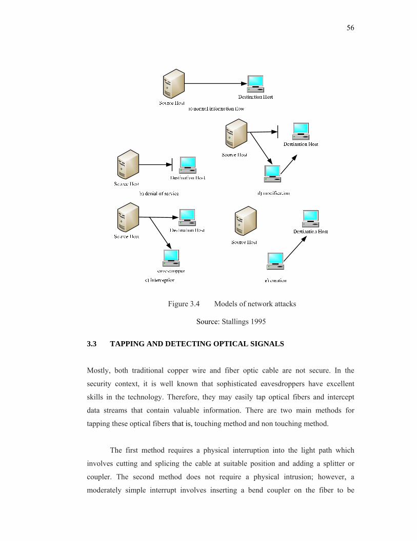
56
Figure 3.4 Models of network attacks
Source: Stallings 1995
3.3 TAPPING AND DETECTING OPTICAL SIGNALS
Mostly, both traditional copper wire and fiber optic cable are not secure. In the
security context, it is well known that sophisticated eavesdroppers have excellent
skills in the technology. Therefore, they may easily tap optical fibers and intercept
data streams that contain valuable information. There are two main methods for
tapping these optical fibers that is, touching method and non touching method.
The first method requires a physical interruption into the light path which
involves cutting and splicing the cable at suitable position and adding a splitter or
coupler. The second method does not require a physical intrusion; however, a
moderately simple interrupt involves inserting a bend coupler on the fiber to be
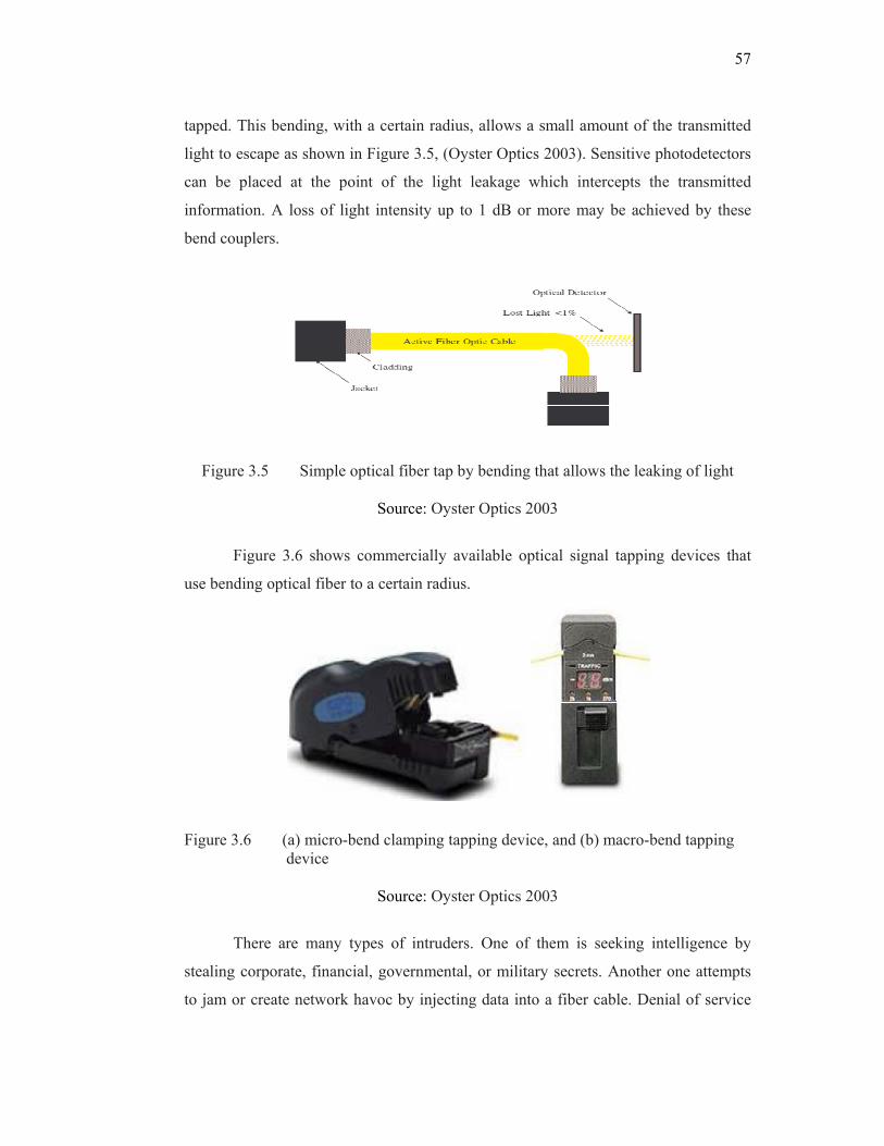
57
tapped. This bending, with a certain radius, allows a small amount of the transmitted
light to escape as shown in Figure 3.5, (Oyster Optics 2003). Sensitive photodetectors
can be placed at the point of the light leakage which intercepts the transmitted
information. A loss of light intensity up to 1 dB or more may be achieved by these
bend couplers.
Figure 3.5 Simple optical fiber tap by bending that allows the leaking of light
Source: Oyster Optics 2003
Figure 3.6 shows commercially available optical signal tapping devices that
use bending optical fiber to a certain radius.
Figure 3.6 (a) micro-bend clamping tapping device, and (b) macro-bend tapping device
Source: Oyster Optics 2003
There are many types of intruders. One of them is seeking intelligence by
stealing corporate, financial, governmental, or military secrets. Another one attempts
to jam or create network havoc by injecting data into a fiber cable. Denial of service

58
attacks can be made via an optical signal injection. Table 3.1 summarizes these
attacks.
Table 3.1 Optical networks attack methods
Attack method Realizes Means
In-Band
Jamming
Service Disruption
An attacker injects a signal designed
to reduce the ability of the receiver to
interpret correctly the transmitted
data
Out-of-Band
Jamming
Service Disruption
An attacker reduces communication
signal component by exploiting leaky
components or cross-modulation
effects
Unauthorized
Observation
Eavesdropping
An attacker listens to the crosstalk
leaking from an adjacent signal
through a shared resource in order to
gain information from the adjacent
signal, the collection of signals by an
attacker for whom they were not
intended).
3.4 EAVESDROPPER CODE PULSE DETECTOR
The design of a communication link, wireless or optical networks, to have low
probability of intercept (LPI) capability is based on the requirement for it to work in
an aggressive environment where the adversary attempts to attack this communication
connection and detect the presence of the information’s transmission. Over the past
period, a huge amount of effort has been spent on the subject of the performance,
configurations, properties and implementation of intercept detectors as well as many
reports and papers are available which describe basic detector topology and optimum
configurations and methods for performance analysis (Dillard 1979; Glenn 1983;

59
Krasner 1982). The results produced lay the required basics and provide bounding
criteria for detectability as a function of the main parameters: detection SNR, data bit
rate, and spread spectrum bandwidth (Simon et al. 2002).
In wireless communication, a classical situation might consist of a surface
vehicle (the communicator) attempting to correspond with a satellite (the receiver) via
transmission of a data, and an adversary search aircraft (the interceptor) whose
mission it is to detect the presence of RF energy corresponding to this communicated
information (Simon et al. 2002). It is obvious that the interceptor’s performance is
considered by his ability to detect that the energy corresponding to the transmission
has been initiated and not by location of the communicator or decoding of the data.
In most security contexts, the adversaries are assumed to be normally familiar
with such intended user information such as his frequency band, modulation format,
and those spread spectrum modulation characteristics such as bandwidth and code
chip rate, which are still insufficient by themselves to allow for decoding of the
desired data codes (Ferguson & Schneier 2003; Stinson 2002). Therefore, in the
absence of information related to the secure codes used to generate the spread
spectrum modulation, the interceptor’s detection strategy is limited to employing
some form of energy detector.
The previous mentioned assumptions also can be applied to the analysis of
eavesdropping form optical CDMA networks with some different aspects. In this case,
these assumptions include that eavesdropping at locations shown in Figure 3.7 carried
out with proper tools that are simple to realize using commercially available
technologies and components, and attackers (eavesdroppers) are technologically
intelligent with knowledge about signals being transmitted in optical CDMA networks
(i.e. architecture of networks, types of signals, data rates, type of encoding, structure
of codes, synchronization, ...etc). According to the well-known Kerckhoffs' principle
in cryptography (Ferguson & Schneier 2003; Stinson 2002), one should assume that
eavesdropper knows everything about cryptographic algorithm except for the key.
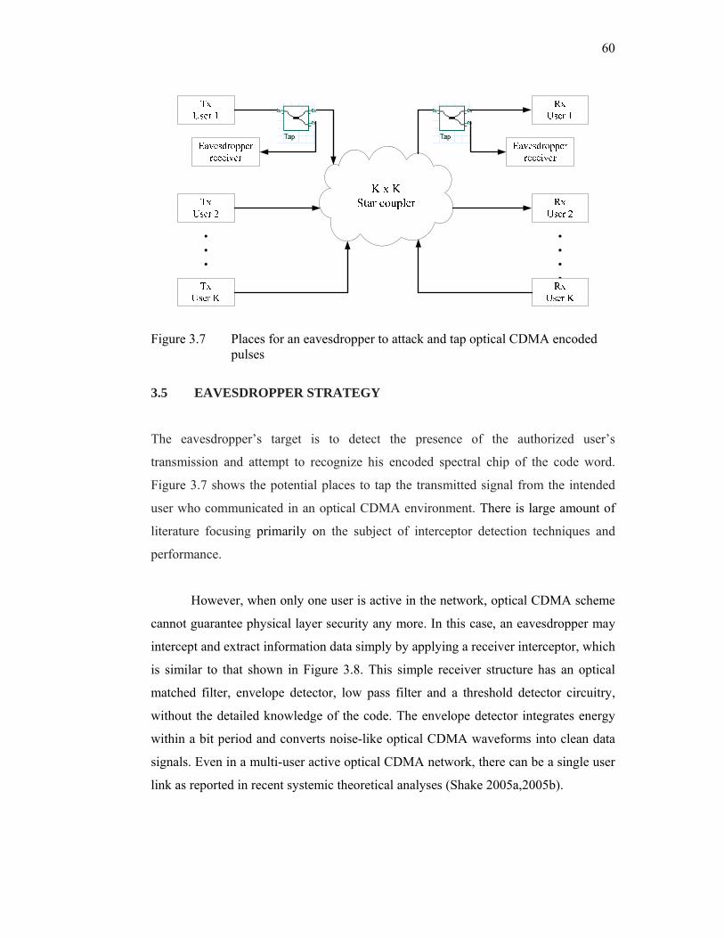
60
Figure 3.7 Places for an eavesdropper to attack and tap optical CDMA encoded pulses
3.5 EAVESDROPPER STRATEGY
The eavesdropper’s target is to detect the presence of the authorized user’s
transmission and attempt to recognize his encoded spectral chip of the code word.
Figure 3.7 shows the potential places to tap the transmitted signal from the intended
user who communicated in an optical CDMA environment. There is large amount of
literature focusing primarily on the subject of interceptor detection techniques and
performance.
However, when only one user is active in the network, optical CDMA scheme
cannot guarantee physical layer security any more. In this case, an eavesdropper may
intercept and extract information data simply by applying a receiver interceptor, which
is similar to that shown in Figure 3.8. This simple receiver structure has an optical
matched filter, envelope detector, low pass filter and a threshold detector circuitry,
without the detailed knowledge of the code. The envelope detector integrates energy
within a bit period and converts noise-like optical CDMA waveforms into clean data
signals. Even in a multi-user active optical CDMA network, there can be a single user
link as reported in recent systemic theoretical analyses (Shake 2005a,2005b).
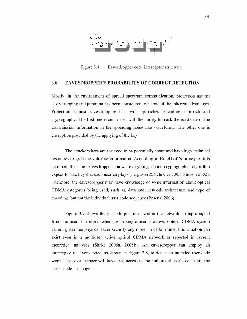
61
Figure 3.8 Eavesdropper code interceptor structure
3.6 EAVESDROPPER’S PROBABILITY OF CORRECT DETECTION
Mostly, in the environment of spread spectrum communication, protection against
eavesdropping and jamming has been considered to be one of the inherent advantages.
Protection against eavesdropping has two approaches: encoding approach and
cryptography. The first one is concerned with the ability to mask the existence of the
transmission information in the spreading noise like waveforms. The other one is
encryption provided by the applying of the key.
The attackers here are assumed to be potentially smart and have high-technical
resources to grab the valuable information. According to Kerckhoff’s principle, it is
assumed that the eavesdropper knows everything about cryptographic algorithm
expect for the key that each user employs (Ferguson & Schneier 2003; Stinson 2002).
Therefore, the eavesdropper may have knowledge of some information about optical
CDMA categories being used, such as, data rate, network architecture and type of
encoding, but not the individual user code sequence (Prucnal 2006).
Figure 3.7 shows the possible positions, within the network, to tap a signal
from the user. Therefore, when just a single user is active, optical CDMA system
cannot guarantee physical layer security any more. In certain time, this situation can
exist even in a multiuser active optical CDMA network as reported in current
theoretical analyses (Shake 2005a, 2005b). An eavesdropper can employ an
interceptor receiver device, as shown in Figure 3.8, to detect an intended user code
word. The eavesdropper will have free access to the authorized user’s data until the
user’s code is changed.
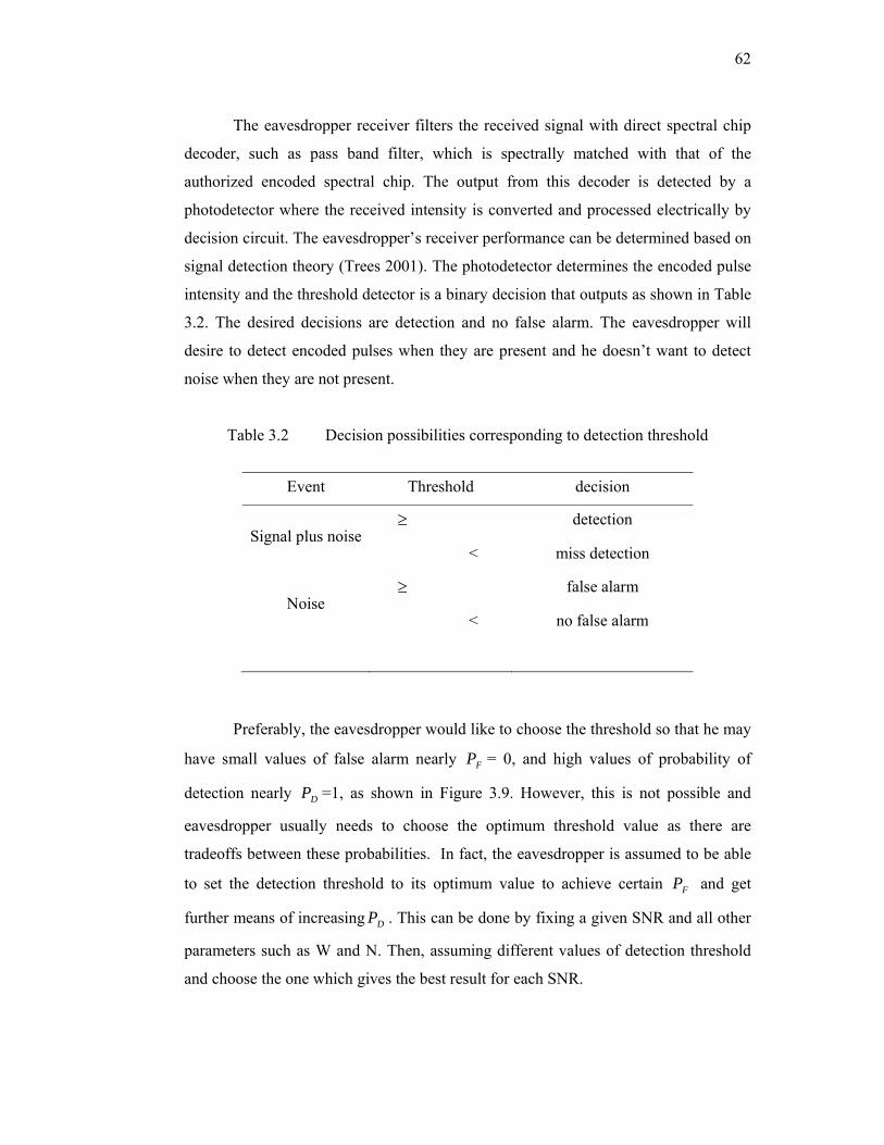
62
The eavesdropper receiver filters the received signal with direct spectral chip
decoder, such as pass band filter, which is spectrally matched with that of the
authorized encoded spectral chip. The output from this decoder is detected by a
photodetector where the received intensity is converted and processed electrically by
decision circuit. The eavesdropper’s receiver performance can be determined based on
signal detection theory (Trees 2001). The photodetector determines the encoded pulse
intensity and the threshold detector is a binary decision that outputs as shown in Table
3.2. The desired decisions are detection and no false alarm. The eavesdropper will
desire to detect encoded pulses when they are present and he doesn’t want to detect
noise when they are not present.
Table 3.2 Decision possibilities corresponding to detection threshold
Event Threshold decision
Signal plus noise≥ detection
< miss detection
Noise ≥ false alarm
< no false alarm
Preferably, the eavesdropper would like to choose the threshold so that he may
have small values of false alarm nearly FP = 0, and high values of probability of
detection nearly DP =1, as shown in Figure 3.9. However, this is not possible and
eavesdropper usually needs to choose the optimum threshold value as there are
tradeoffs between these probabilities. In fact, the eavesdropper is assumed to be able
to set the detection threshold to its optimum value to achieve certain FP and get
further means of increasing DP . This can be done by fixing a given SNR and all other
parameters such as W and N. Then, assuming different values of detection threshold
and choose the one which gives the best result for each SNR.

63
1 2 3 4 5 6 7 8 9 10 11 12 13 14 15 16 17 18
0.1
0.2
0.3
0.4
0.5
0.6
0.70.750.8
0.850.9
0.950.9999
Encoded pulse SNR - dB
Pro
babi
lity
of d
etec
tion
PD
Figure 3.9 Probability of detection versus encoded pulse SNR, for several FP values
Source: Mahafza & Elsherbeni 2003
The probability that the eavesdropper can detect the authorized user’s entire
code word pulses with no errors will depend on the type of detection scheme and on
the amount of time the eavesdropper observes the user’s signal for each pulse
detection. Based on classical detection analysis (Trees 2001), this probability can be
calculated from two quantities the probability of missing a transmitted pulse in a given
time bin, MP , and the probability of falsely detecting a pulse in a bin where none was
transmitted, FP .
Terming MP for the probability of miss detection, the probability of detection
is (1 )D MP P= − . Also, letting FP as the probability false alarm, the probability of no
false is alarm (1 )nF FP P= − .
In fact, the interceptor desires a reasonably high probability that such code
pulse will be detected. Therefore, the detection probability DP should be close to
unity. Alternatively, the interceptor does not desire his receiver to specify a state of

64
signal detection when no real signal is present. Such a state of false alarm caused by
system noise should have a very low probability FP of occurrence. Typical values of
DP and FP might be DP = 0.9 and FP = 10-6.
Certainly the simplest and easiest way to implement detector, by the
eavesdropper, is the band-limited energy detector or a tuned bandwidth filter which
can be matched to particular spectral chip bandwidths that are corresponding to the
optical CDMA code pulses. Figure 3.8 shows one of these simple eavesdropper code
interceptors structure which consists of a band pass filter (BPF) of center wavelength
λ0 and matched to spectral chip code bandwidth δυ, a photodetector operating as a
square-law envelope detector to detect the output of the matched BPF, a low pass
filter with a cut off electrical bandwidth approximately equal to 75 % of the user data
bit rate and a comparator that evaluate the integrator output against a threshold value
in order to decide if a signal is received for each spectral chip code pulse.
An eavesdropper can implement an attack device to detect an intended user
code word as shown in Figure 3.8. Once a user’s code word is detected by the
eavesdropper, the eavesdropper has free access to the user’s data until the user’s code
is changed.
If the code interceptor makes a code word decision based on observing the
transmitted signal for an encoded spectral amplitude coding (SAC) optical CDMA
data bit interval, the overall probability of error-free code word detection is given by:
( )(1 ) (1 )W N W
correct M FP P P −= − − (3.1)
exp( )Fo
PNγ
= − (3.2)
(γ is the detection threshold and oN is the noise power spectral density).

65
Since, MP is the probability of missing a transmitted pulse in a given time bin,
then the probability of not missing a transmitted pulse is denoted as DP , sometimes
referred as the probability of detection.
(1 )D MP P= − (3.3)
( 2 / , 2 ln )D o FP Q E N P= − (3.4)
( E refers here to the energy in an individual code pulse not the energy received during
an entire data bit). Q is a function commonly called Marcum’s Q function (Trees
2001).
2 2
0( , ) exp( ) ( )2
zQ z I z dzβ
αα β α∞ +
≅ −∫ (3.5)
Eq. (3.1) can be written as:
( )
[ ( 2 / , (2 )] [1 exp( )]N WW
correct o o oP Q E N N Nγ γ−
= − − (3.6)
where, / oE N is the single pulse signal to noise ratio and γ is detection threshold.
W and N represents code weight and code length of a spectral amplitude code
OCDMA, respectively.
The intruder can choose the optimum threshold value. He can use different
values of optimum threshold and choose the one which gives the best results for each
SNR. To get optimum threshold, we need to fix a given SNR and all other parameters.
We search for the optimum threshold that maximizes correctP . This is the corresponding
value for that given SNR. Then we repeat the process for another SNR point and so
on. Searching can be done by letting optimum threshold equals a very small value and
increase it in steps (every time we calculate correctP ), we will notice that correctP
increases then at a certain point of optimum threshold correctP will start to decrease.
66
Then the maximizing optimum threshold is the one before last (i.e., the one that gives
max correctP ).
3.7 SIMULATION SOFTWARE AND PARAMETERS USED
On an almost daily basis, optical communication systems are increasing in
complexity. Therefore, simulation of optical communication systems has become an
essential requirement due to the complex interactions within and between optical
components, and the need for rapid design cycles using the latest technologies. The
design and analysis of these systems, which normally include nonlinear devices and
non-Gaussian noise sources, are highly complex and extremely time-intensive.
Therefore, these tasks can now only be carried out efficiently and effectively with the
assist of advanced simulation software tools.
Parts of this work have been carried out using simulation software, OptiSystem
6.0 and 7.0 from Optiwave. OptiSystem is a pioneering optical communication system
simulation package that designs, tests, and optimizes virtually any type of optical link
in the physical layer of a broad spectrum of optical networks, from analog video
broadcasting systems to intercontinental backbones.
The extensive library of active and passive components includes realistic,
wavelength-dependent parameters. Parameter sweep function allows the user to
investigate the effect of particular device specifications on system performance.
OptiSystem evaluates the signals by performing suitable algorithms related to the
required simulation accuracy and efficiency. In order to predict the system
performance, OptiSystem calculates parameters such as BER and Q-Factor using
numerical analysis or semi-analytical techniques for systems limited by inter symbol
interference and noise.
The simulation analysis has been carried out for various SAC optical CDMA
systems under transmission security investigation based on the scope of the study in
67
Figure 1.1. Therefore, each stage has been implemented and tested by introducing the
suitable sets of design parameter based on the SAC code type. The performance of
each system is measured by using different visual analyzers such as optical spectrum
analyzer (OSA), optical power meter, and BER analyzer. The design parameters are
the layout system parameters that we can vary or change in order to investigate their
effect on the transmission security performance. The design parameters used are bit
rate, transmit power and encoded spectral chip bandwidth.
3.8 TAPPING ENCODED SPECTRAL CHIP BANDWIDTH (ESCB) FROM SAC OPTICAL CDMA SYSTEMS
Optical CDMA is a multiplexing method modified from the successful realization in
wireless networks. It has become a promising technology to employ all optical
communication and networking that use optical signal processing directly combining
the advantages of electrical CDMA with the bandwidth predominance of fiber optic
and optical signal processing devices (Yin & Richardson 2007).
In 1995, Kavehrad and Zaccarin (Kavehrad & Zaccarin 1995) proposed the
first SAC optical CDMA system. Their technique involves dispersing the frequency
content of a broadband source signal followed by spatial filtering with an amplitude
mask. A code is represented by (N, w, λ) where N, w, and λ are code length, code
weight, and in-phase cross correlation, respectively. Spectral amplitude coding optical
CDMA systems using codes, which have the code property with low in-phase cross
correlation, can eliminate the interference signals, such as M-sequence (Peterson et al.
1995), Hadamard (Zou,Ghafouri-Shiraz et al. 2001), modified double weight (MDW)
(Aljunid et al. 2004), and modified quadratic congruence (MQC) (Zou,Shalaby et al.
2001) codes. However, as broad-band thermal source are used in such system, the
phase-induced intensity noise (PIIN) that is due to the intensity fluctuation of thermal
source severely affects the system performance (Smith et al. 1998).
Employing the basic MDW code as shown in Table 3.3, Figure 3.10 is
obtained, which shows the eavesdropper probability of correct detection as a function
of signal to noise ratio for a single detected code pulse. For probability of correct
detection of 0.5, an eavesdropper receiver would need to detect SNR of 8 dB. As the
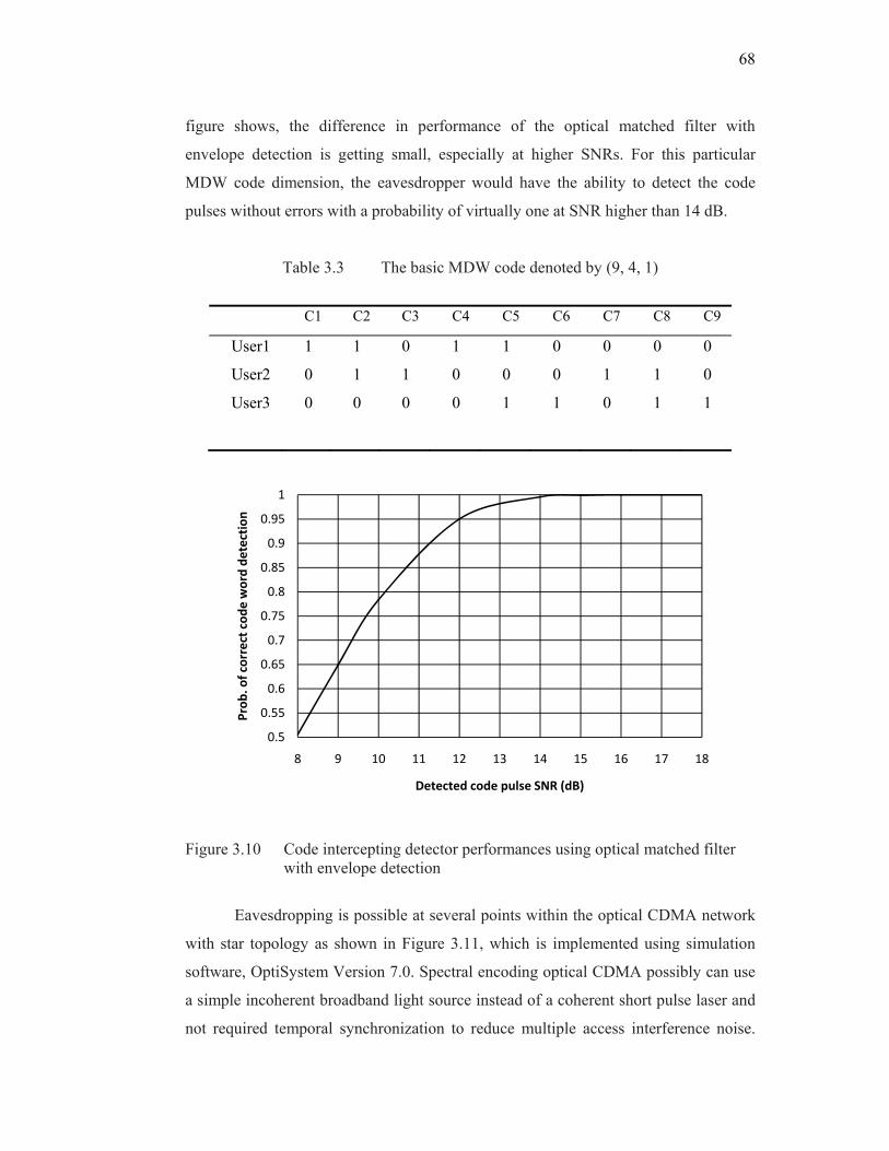
68
figure shows, the difference in performance of the optical matched filter with
envelope detection is getting small, especially at higher SNRs. For this particular
MDW code dimension, the eavesdropper would have the ability to detect the code
pulses without errors with a probability of virtually one at SNR higher than 14 dB.
Table 3.3 The basic MDW code denoted by (9, 4, 1)
C1 C2 C3 C4 C5 C6 C7 C8 C9
User1 1 1 0 1 1 0 0 0 0
User2 0 1 1 0 0 0 1 1 0
User3 0 0 0 0 1 1 0 1 1
Figure 3.10 Code intercepting detector performances using optical matched filter with envelope detection
Eavesdropping is possible at several points within the optical CDMA network
with star topology as shown in Figure 3.11, which is implemented using simulation
software, OptiSystem Version 7.0. Spectral encoding optical CDMA possibly can use
a simple incoherent broadband light source instead of a coherent short pulse laser and
not required temporal synchronization to reduce multiple access interference noise.
0.5
0.55
0.6
0.65
0.7
0.75
0.8
0.85
0.9
0.95
1
8 9 10 11 12 13 14 15 16 17 18
Prob
. of correct cod
e word de
tection
Detected code pulse SNR (dB)
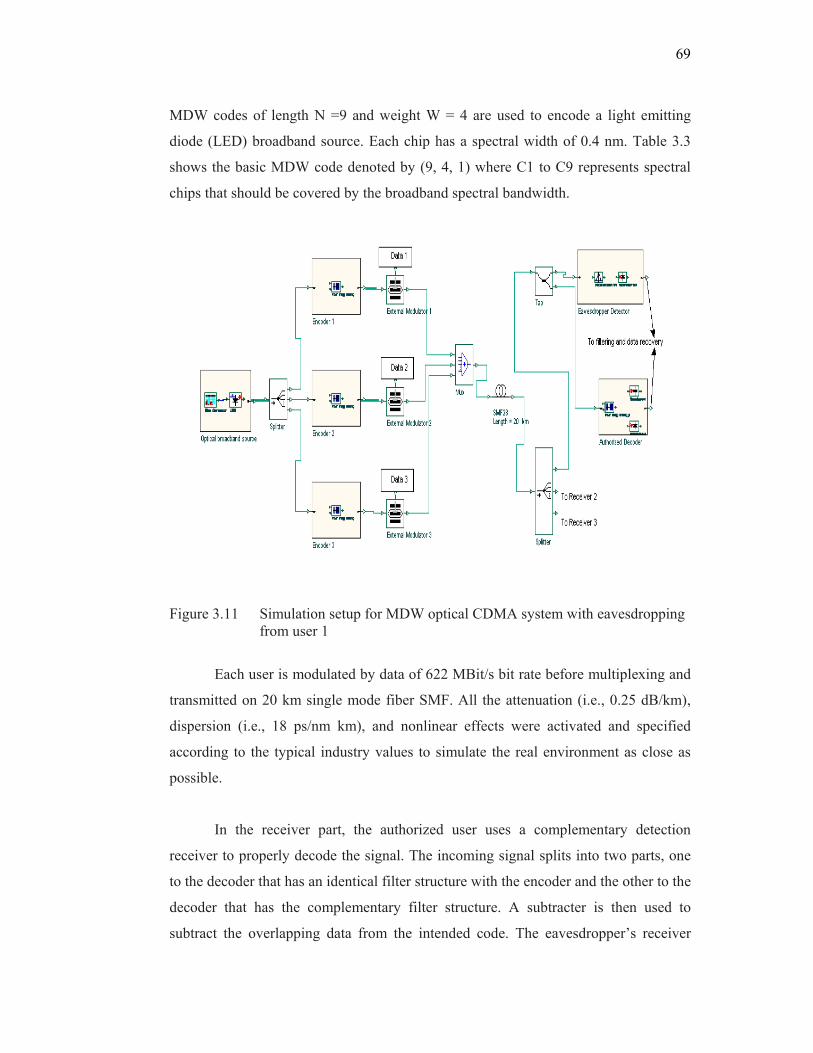
69
MDW codes of length N =9 and weight W = 4 are used to encode a light emitting
diode (LED) broadband source. Each chip has a spectral width of 0.4 nm. Table 3.3
shows the basic MDW code denoted by (9, 4, 1) where C1 to C9 represents spectral
chips that should be covered by the broadband spectral bandwidth.
Figure 3.11 Simulation setup for MDW optical CDMA system with eavesdropping from user 1
Each user is modulated by data of 622 MBit/s bit rate before multiplexing and
transmitted on 20 km single mode fiber SMF. All the attenuation (i.e., 0.25 dB/km),
dispersion (i.e., 18 ps/nm km), and nonlinear effects were activated and specified
according to the typical industry values to simulate the real environment as close as
possible.
In the receiver part, the authorized user uses a complementary detection
receiver to properly decode the signal. The incoming signal splits into two parts, one
to the decoder that has an identical filter structure with the encoder and the other to the
decoder that has the complementary filter structure. A subtracter is then used to
subtract the overlapping data from the intended code. The eavesdropper’s receiver

70
structure has a band pass filter with 20 GHz bandwidth, a photodetector and low pass
filter with electrical bandwidth of 0.75 times bit rate. Its performance is based on
measuring a single spectral chip signal and then calculate signal to noise ratio (SNR).
An eavesdropper may intercept and extract information data by tuning a
narrow band pass filter across the entire wavelength range and select one spectral chip
as shown in Figure 12(a). In this case, an eavesdropper had the information about the
spectral bandwidth of one spectral chip and the type of the encoding system being
used and did not know the code word itself.
When only one user is active in the network, OCDMA scheme cannot
guarantee physical layer security any more. Even in a multi-user OCDMA network,
there can be a single user link active. Figure 3.12(b) shows the encoded spectrum of
the transmitted signal for three users measured by a spectrum analyzer with resolution
of 0.01 nm. The effective power of the broadband source at the eavesdropper
photodetector is measured to be -33 dBm for each single spectral chip pulse.
Figure 3.12 Encoded spectrum detected by eavesdropper with 20 % tapping efficiency
‐60‐58‐56‐54‐52‐50‐48‐46‐44‐42‐40‐38‐36‐34‐32‐30
1548.5 1549 1549.5 1550 1550.5 1551 1551.5 1552 1552.5 1553 1553.5
Receiver sen
sistivity (dBm
)
Spectral wavelengths (nm)
(a)
(b)
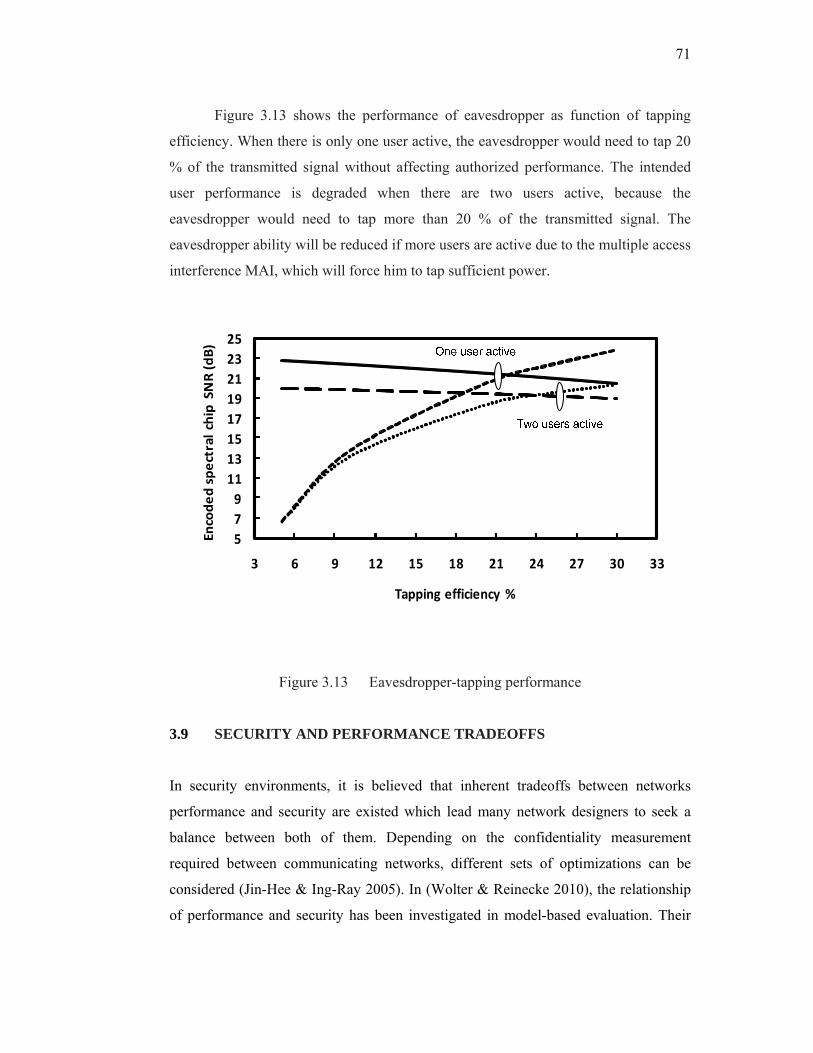
71
Figure 3.13 shows the performance of eavesdropper as function of tapping
efficiency. When there is only one user active, the eavesdropper would need to tap 20
% of the transmitted signal without affecting authorized performance. The intended
user performance is degraded when there are two users active, because the
eavesdropper would need to tap more than 20 % of the transmitted signal. The
eavesdropper ability will be reduced if more users are active due to the multiple access
interference MAI, which will force him to tap sufficient power.
5791113151719212325
3 6 9 12 15 18 21 24 27 30 33
Encoded spectral chip SNR (dB)
Tapping efficiency %
Figure 3.13 Eavesdropper-tapping performance
3.9 SECURITY AND PERFORMANCE TRADEOFFS
In security environments, it is believed that inherent tradeoffs between networks
performance and security are existed which lead many network designers to seek a
balance between both of them. Depending on the confidentiality measurement
required between communicating networks, different sets of optimizations can be
considered (Jin-Hee & Ing-Ray 2005). In (Wolter & Reinecke 2010), the relationship
of performance and security has been investigated in model-based evaluation. Their
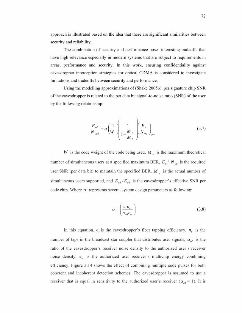
72
approach is illustrated based on the idea that there are significant similarities between
security and reliability.
The combination of security and performance poses interesting tradeoffs that
have high relevance especially in modern systems that are subject to requirements in
areas, performance and security. In this work, ensuring confidentiality against
eavesdropper interception strategies for optical CDMA is considered to investigate
limitations and tradeoffs between security and performance.
Using the modelling approximations of (Shake 2005b), per signature chip SNR
of the eavesdropper is related to the per data bit signal-to-noise ratio (SNR) of the user
by the following relationship:
0 0
1 1
1
ed u
Aed u spec
T
E EMN W NM
σ
⎛ ⎞⎜ ⎟⎛ ⎞⎛ ⎞ ⎜ ⎟= ⎜ ⎟⎜ ⎟
⎝ ⎠ ⎜ ⎟ ⎝ ⎠−⎜ ⎟⎝ ⎠
(3.7)
W is the code weight of the code being used, T
M is the maximum theoretical
number of simultaneous users at a specified maximum BER, uE / 0uN is the required
user SNR (per data bit) to maintain the specified BER, A
M is the actual number of
simultaneous users supported, and edE / edE is the eavesdropper’s effective SNR per
code chip. Where σ represents several system design parameters as following:
t u
ed u
e ne
σα⎛ ⎞
= ⎜ ⎟⎝ ⎠
(3.8)
In this equation, te is the eavesdropper’s fiber tapping efficiency, un is the
number of taps in the broadcast star coupler that distributes user signals, edα is the
ratio of the eavesdropper’s receiver noise density to the authorized user’s receiver
noise density, ue is the authorized user receiver’s multichip energy combining
efficiency. Figure 3.14 shows the effect of combining multiple code pulses for both
coherent and incoherent detection schemes. The eavesdropper is assumed to use a
receiver that is equal in sensitivity to the authorized user’s receiver ( edα = 1). It is

73
assumed that the total number of taps in the star coupler, shown in Figure 3.7, is un =
100 with a tapping efficiency of te = 0.01. Since, ue is equal to one and between zero
and one for coherent and incoherent detection respectively (Mahafza & Elsherbeni
2003 ), coherent detection with combining signals shows better confidentiality than
the incoherent one.
Figure 3.14 Effect of combining multiple code pulses for both coherent and incoherent detection schemes
The per code chip eavesdropper’s SNRs as a function of the theoretical system
capacity are shown Figure 3.15. If the authorized users transmit sufficient power so
that 50%, 65% and 75% of the theoretical system capacity is attained for code weights
W of 4, 6 and 8 respectively, the eavesdropper has SNR of 15 dB. An optical matched
filter receiver followed by envelope detection theoretically requires a (peak) SNR of
approximately 15 dB to produce the required raw detector BER of 10-4. Error
correction codes used in commercial high-rate optical telecommunication equipment
can produce the maximum acceptable system BER 10-9.
0
1
2
3
4
5
6
7
8
9
10
0 0.1 0.2 0.3 0.4 0.5 0.6 0.7 0.8 0.9 1
System
design pa
rameters σ
Multichip combining efficiency

74
Figure 3.15 Per chip code SNR as a function of theoretical system capacity
The Figure above shows a contradiction between network system performance
and security. Increasing the network system capacity will lead the eavesdropper to
detect high SNRs. Another limitation can be shown in Figure 3.16, where high
specified SNRs will increase the eavesdropper possibility of attacks.
Figure 3.16 Per chip code SNR as a function of theoretical system capacity for different specified authorized SNRs
10
12
14
16
18
20
22
24
26
10 20 30 40 50 60 70 80 90 100
Eav
esdo
pper
's e
ffec
tive
SNR
per
cod
e ch
ip
(dB
)
Theoretical Capacity MA/MT %
W=4 W=6 W=8
0
5
10
15
20
25
30
10 20 30 40 50 60 70 80 90 100
Eavesdropp
er encod
ed pule SN
R (dB)
Overall system efficiency %
5 dB 10 dB 15 dB 20 dB
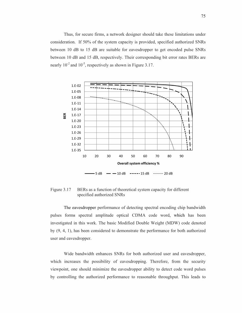
75
Thus, for secure firms, a network designer should take these limitations under
consideration. If 50% of the system capacity is provided, specified authorized SNRs
between 10 dB to 15 dB are suitable for eavesdropper to get encoded pulse SNRs
between 10 dB and 15 dB, respectively. Their corresponding bit error rates BERs are
nearly 10-2 and 10-5, respectively as shown in Figure 3.17.
Figure 3.17 BERs as a function of theoretical system capacity for different specified authorized SNRs
The eavesdropper performance of detecting spectral encoding chip bandwidth
pulses forms spectral amplitude optical CDMA code word, which has been
investigated in this work. The basic Modified Double Weight (MDW) code denoted
by (9, 4, 1), has been considered to demonstrate the performance for both authorized
user and eavesdropper.
Wide bandwidth enhances SNRs for both authorized user and eavesdropper,
which increases the possibility of eavesdropping. Therefore, from the security
viewpoint, one should minimize the eavesdropper ability to detect code word pulses
by controlling the authorized performance to reasonable throughput. This leads to
1.E‐35
1.E‐32
1.E‐29
1.E‐26
1.E‐23
1.E‐20
1.E‐17
1.E‐14
1.E‐11
1.E‐08
1.E‐05
1.E‐02
10 20 30 40 50 60 70 80 90
BER
Overall system efficiency %
5 dB 10 dB 15 dB 20 dB

76
security impact over system performance as shown in Figure 3.18. The dashed and
solid lines represent theoretical results for authorized user and eavesdropper,
respectively. Whereas, triangle and rectangle symbols represent simulation results for
authorized user and eavesdropper, respectively.
Figure 3.18 Security impact over system performance for spectral amplitude optical CDMA based on MDW code systems
Thus, to improve the degree of security, we have to reduce the bandwidth of
the encoding chip bandwidth pulses. This reduction should not affect the system
performance. For example, if a spectral chip is reduced from 50 GHz to 25 GHz, the
authorized user and eavesdropper could obtain SNRs of 22 dB and 16 dB respectively.
These values are corresponding to bit error rate BERs of nearly 10-12 and 10-5
respectively. The maximum acceptable system BER is assumed to be 10-9. Decreasing
spectral chip, below than 25 GHz, will affect the authorized performance forcing him
to use error correction codes techniques used in commercial optical communications.
In communication systems, there is a tradeoff between data bit rate and the
provided system number of channels. Data bit rate x sequence code length = encoded
chip rate. Generally, in optical CDMA analysis, in order to reduce the MAI
2
6
10
14
18
22
26
30
34
0 5 10 15 20 25 30 35 40 45 50 55
SNR (dB)
Single spectral chip bandwidth (GHz)
77
limitations, the data bit rate should be reduced. Figure 3.19 shows the impact of data
bit rates on the eavesdropper performance. Increasing the bit rate will decrease the
eavesdropper SNR, making the signal to be more sensitive to fiber dispersion and
receiver circuitry noise.
0
5
10
15
20
25
0 500 1000 1500 2000 2500
Eav
esdr
oppe
r SN
R (
dB)
Data bit rate (Mb/s)
Figure 3.19: Eavesdropper SNR vs bit rates
3.10 SUMMARY
This chapter describes the transmission security performance analysis of SAC optical
CDMA. A brief overview of the security definitions and network security issues is
given with concentration on the interception attack. The eavesdropper interception
strategy is based on isolating the authorized user, and this situation could also be
possible even in the multi user active optical CDMA network, there can be a single
user link. The eavesdropper performance is investigated based on calculating the
probability of correct detection correctP of the encoded spectral chip bandwidth pulses.
In this calculation, the eavesdropper is required to know or estimate such parameters
as the code weight W, code length N, eavesdropper SNR and detection threshold. In
addition to that, limitations and tradeoffs between security and performance are given.
CHAPTER IV
SECURITY PERFORMANCE FOR SPECTRAL AMPLITUDE CODE OPTICAL CDMA
4.1 INTRODUCTION
Security is an increasingly important issue for many communication applications. For
practical optical network systems, it may be desirable to transmit confidential
information over public or private networks. While various algorithms can be applied
to electronically encrypt data, implementation may lead to an electronic bottleneck for
high speed data transmission. In contrast, the optical coding schemes potentially
provide high levels of security, but are effectively transparent, since the encryption is
performed optically, and hence are suitable for high bit-rate applications (Stavroulakis
2006 ).
In this chapter, we have presented the eavesdropper performance results based
on the methodology that has been discussed in Chapter III. We have applied both
modified double weight (MDW) (Aljunid et al. 2004) and modified quadratic
congruence (MQC) (Zou et al. 2001) to investigate the eavesdropper probability of
correct detection. In addition to that, the effect of the encoded spectral chip bandwidth
on transmission security performance is included. Shot, thermal, and phase induced
intensity noise (PIIN) are considered to be the main noise contribution in our analysis.
Furthermore, we have simulated SAC optical CDMA systems using Optisystem
software version 7 to present eavesdropper performance.
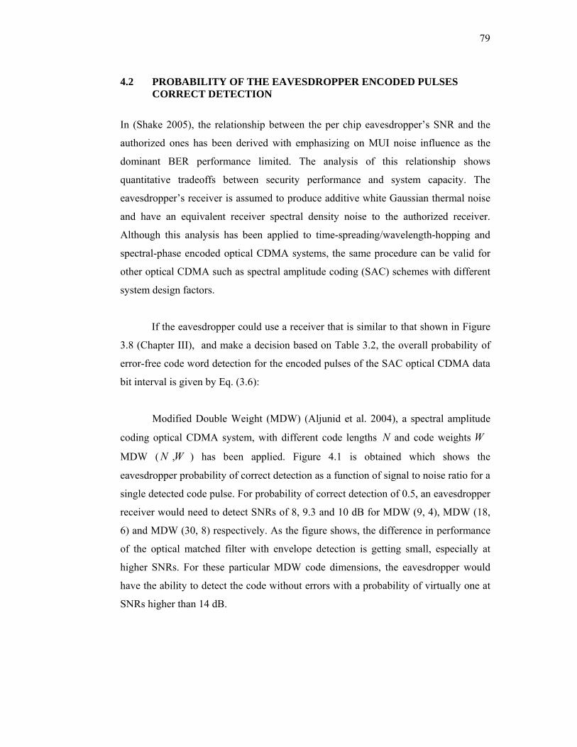
79
4.2 PROBABILITY OF THE EAVESDROPPER ENCODED PULSES CORRECT DETECTION
In (Shake 2005), the relationship between the per chip eavesdropper’s SNR and the
authorized ones has been derived with emphasizing on MUI noise influence as the
dominant BER performance limited. The analysis of this relationship shows
quantitative tradeoffs between security performance and system capacity. The
eavesdropper’s receiver is assumed to produce additive white Gaussian thermal noise
and have an equivalent receiver spectral density noise to the authorized receiver.
Although this analysis has been applied to time-spreading/wavelength-hopping and
spectral-phase encoded optical CDMA systems, the same procedure can be valid for
other optical CDMA such as spectral amplitude coding (SAC) schemes with different
system design factors.
If the eavesdropper could use a receiver that is similar to that shown in Figure
3.8 (Chapter III), and make a decision based on Table 3.2, the overall probability of
error-free code word detection for the encoded pulses of the SAC optical CDMA data
bit interval is given by Eq. (3.6):
Modified Double Weight (MDW) (Aljunid et al. 2004), a spectral amplitude
coding optical CDMA system, with different code lengths N and code weights W
MDW (N ,W ) has been applied. Figure 4.1 is obtained which shows the
eavesdropper probability of correct detection as a function of signal to noise ratio for a
single detected code pulse. For probability of correct detection of 0.5, an eavesdropper
receiver would need to detect SNRs of 8, 9.3 and 10 dB for MDW (9, 4), MDW (18,
6) and MDW (30, 8) respectively. As the figure shows, the difference in performance
of the optical matched filter with envelope detection is getting small, especially at
higher SNRs. For these particular MDW code dimensions, the eavesdropper would
have the ability to detect the code without errors with a probability of virtually one at
SNRs higher than 14 dB.

80
Figure 4.1 Code intercepting detector performances using optical matched filter with envelope detection
The solid line in Figure 4.1 represents the eavesdropper performance in the
case of using two dimensions optical CDMA encoding system such as wavelength
hopping-time spreading WH-TS ( tn , nλ ,W ) (Deng et al. 2008), where tn , nλ and W
are time slots, wavelengths and code weight, respectively. WH-TS (8, 8, 4) has better
security than MDW (9, 4) even though they have the same code weight. It is clear that
MDW with code weight 8W = has slightly the same security performance as WH-TS
(8, 8, 4). The higher the code space size, the better the security performance available
from SAC optical CDMA encoding.
Furthermore, employing the MQC (Zou et al. 2001) codes with different prime
numbers, Figure 4.2 is obtained, which shows the eavesdropper probability of correct
detection as a function of signal to noise ratio for a single detected code pulse. For
probability of correct detection of 0.5, an eavesdropper receiver would need to detect
SNRs of 8.3 dB, 10.3 dB, 11.1 dB, and 11.4 dB for MQC codes with prime numbers
of 3, 7, 11, and 13 respectively. As the figure shows, the difference in performance is
getting small, especially at higher SNRs. For these particular MQC code dimensions,
the eavesdropper would have the ability to detect the code pulses without errors with a
0.5
0.55
0.6
0.65
0.7
0.75
0.8
0.85
0.9
0.95
1
8 9 10 11 12 13 14 15 16 17 18
prob
. of e
rror‐free code
word de
tection
SNR (dB)
MDW(9,4) MDW(18,6) MDW(30,8) WH‐TS(8,8,4)

81
probability of virtually one at SNR higher than 14 dB. On the other hand, this
difference becomes slightly big at low SNRs especially for those codes with small p
values.
Figure 4.2 MQC eavesdropper performance
From Figures 4.1 and 4.2, it is clear that the MQC codes have slightly better
security performance than the MDW codes. For example, this comparison is done
based on the similarity of their code dimensions. Particularly, MDW (9, 4) and MQC
with p=3 have similar code weight because MQC with p=3 has a code weight of 4
(p+1=4), but they have different code length, 9 and 12 for MDW and MQC
respectively. Therefore, MQC (12, 4) has 0.3 dB preference over MDW (9, 4).
4.3 EAVESDROPPER SNR: A SPECTRALLY ENCODED PULSE BANDWIDTH EFFECTS
The attackers here are assumed to be potentially intelligent and have high-technical
resources to commandeer the valuable information. According to Kerckhoff’s
principle which assumes that eavesdropper knows everything about cryptographic
algorithm except for the key that each user employs (Ferguson & Schneier 2003;
Stinson 2002). Therefore, the eavesdropper may know some information about types

82
of optical CDMA being used, such as, data rate, network architecture and type of
encoding, but not the individual user code sequence.
4.3.1 Eavesdropper Receiver and Noise Considerations
In a communication system, realizing and understanding the sources of noise is
essential for a receiver performance to be accurately characterized. The quantity of
noise that can exist in a receiver will be the main element that determines the
receiver’s sensitivity (Alexander 1997).
In practical transmission system, noise is defined as any unwanted signal
present in the receiver other than the desired signal. The noise sources, usually noticed
in an optical receiver, including that of optical and electronics origin, can be
categorized into a few classes. The first are intrinsic noise sources originating from the
fundamental natural effects of the system design itself, especially in the opto-
electronic and electronic devices used to construct the receiver. Another noises
originating from optical sources, such as broadband sources used to implement the
transmission section, may degrade the system performance. Examples of the intrinsic
noises are thermal noise, dark current noise, electronic shot noise, relative intensity
noise (RIN), and phase induced intensity noise (PIIN). The second are coupled noise
sources that originate from interactions between the receiver circuitry and the
surrounding environment. They can be found in solar, nearby electrical transmission
lines, power supplies, etc.
The linear relationship between the received optical power and the
photocurrent generated in the photodetector is considered to be the distinguishing
characteristic in optical transmission system. This is the result of the square-law
photodetection operation, converting the optical intensity into current intensity.
Subsequently, the electrical signal amplitude (current or voltage) is then proportional
to the received optical power. Generally, the data bit is represented by the photodiode
photocurrent which is sampled at the decision circuit and is affected by all noise
contributions. The obtained sample then represents the sum of the exact signal
involved and several noise terms.

83
In spectral amplitude coding optical CDMA, most noise contributions result
from thermal noise, shot noise and PIIN (Smith et al. 1998; Wei et al. 2001). Dark
current noise, RIN and the coupled noise have been ignored. A simple schematic
block diagram of spectral amplitude code optical CDMA system consisting of K users
is illustrated in Figure 4.3.
Figure 4.3 The system architecture of spectral amplitude code optical CDMA system network
4.3.2 Eavesdropper SNR Analysis
Theoretical analysis is presented for the eavesdropper encoded pulses detection based
on Spectral Amplitude Coding (SAC) optical CDMA systems. We have applied the
Modified Quadratic Congruence (MQC) code to investigate the effect of the encoded
spectral chip on security performance. Further information of MQC can be found in
(Zou et al. 2001). Given a prime number p, the MQC code has the following
properties: code length is (p2 + p), its weight is (p+1), and a total number of users p2.
To investigate eavesdropper SNR, we need to use the same analysis proposed
by (Zou et al. 2001). His analysis was based on the complimentary detection for the
occupied code length of an authorized user, where the multiple access interference
(MAI) effect has been reduced to minimum. The eavesdropper receiver filters the

84
received signal with pass band filter (direct single spectral chip decoder) which is
spectrally matched with that of the authorized decoder spectral chip bandwidth. The
output from this decoder is detected by a photodetector where the received intensity is
converted and processed electrically by decision circuit.
As mentioned before, that shot, thermal, and PIIN noises are considered to be
the main noise contribution in our analysis. It has been shown that the photocurrent
variance due to the complementary detection of an ideally unpolarized thermal light
source is proposed by (Zou et al. 2001), which is used for SAC optical CDMA
encoding systems, the eavesdropper photocurrent variance resulting from the use of
photodetector as shown in Figure 3.8 (Chapter III) can be expressed as:
2 2 2 2
1 2 thI I I I⟨ ⟩ = ⟨ ⟩ + ⟨ ⟩ + ⟨ ⟩ (4.1)
where, 2I is the total noise power, 21I is the shot noise, 2
2I is the Phase Induced
Intensity Noise (PIIN), and 2thI is the thermal noise.
Coherent time of thermal source cτ is given by (Smith et al. 1998):
2
02
0
( )
( )
G v dv
cG v dv
τ
∞
∞⎡ ⎤⎢ ⎥⎢ ⎥⎣ ⎦
∫=
∫
(4.2)
where G(v) is the power spectral density (PSD) of the received optical pulses which
follow Gaussian approximation (Zou et al. 2001):
}{1 1
( ) ( ) ( 2 2) ( 2 )2 2K N
srk k o o
k i
P v vr v d c i u v v N i u v v N iv N N= =
Δ Δ⎡ ⎤ ⎡ ⎤= − − − + − − − − − +Δ ⎣ ⎦ ⎣ ⎦∑ ∑ (4.3)

85
where srP is the effective power of a broadband source at the receiver, vΔ is optical
source bandwidth, K is the active users and N is the MQC code length, kd is the data
bit value of the Kth user that is “1” or “0”, and ( )u v is the unit step function expressed
as:
1, 0( )
0, 0v
u vv≥⎧
= ⎨ <⎩ (4.4)
Therefore, the PSD of the eavesdropper photodiode detector, during single
data bit period, can be expressed written as:
}{1 1
( ) ( ) ( ) .
( 2 2) ( 2 )2 2
K Nsr
K K lK i
o o
PG d c i c i
v vu v v N i u v v N iN N
ν ν= =
= Δ
Δ Δ⎡ ⎤ ⎡ ⎤− − − + − − − − − +⎣ ⎦ ⎣ ⎦
∑ ∑ (4.5)
{ }1 1
( ) ( ) ( )K N
srK K l
K i
PG d c i c i u Nνν ν
= =
Δ⎡ ⎤= Δ ⎣ ⎦∑ ∑ (4.6)
The incident optical power on the eavesdropper photodetector:
1 10 0
( ) ( ) ( )K N
srK K l
K i
PG d d c i c i u dNνν ν ν
ν
∞ ∞
= =
⎡ ⎤⎧ Δ ⎫⎡ ⎤= ⎨ ⎬⎢ ⎥⎢ ⎥Δ ⎣ ⎦⎩ ⎭⎣ ⎦∑ ∑∫ ∫ (4.7)
The MQC code properties required for eavesdropper direct detection scheme
that employing the receiver structure as shown in Figure 3.8:
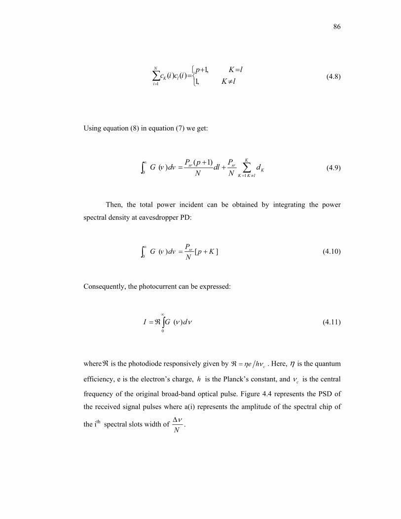
86
1
1,( ) ( )
1,
N
K li
p K lc i c i
K l=
+ =⎧=⎨ ≠⎩
∑ (4.8)
Using equation (8) in equation (7) we get:
01
( 1)( )K
sr srK
K K l
P p PG v dv dl dN N
∞
= ≠
+= + ∑∫ (4.9)
Then, the total power incident can be obtained by integrating the power
spectral density at eavesdropper PD:
0( ) [ ]srPG v dv p K
N∞
= +∫ (4.10)
Consequently, the photocurrent can be expressed:
0
( )I G dν ν∞
= ℜ∫ (4.11)
whereℜ is the photodiode responsively given by ce hη νℜ = . Here, η is the quantum
efficiency, e is the electron’s charge, h is the Planck’s constant, and cν is the central
frequency of the original broad-band optical pulse. Figure 4.4 represents the PSD of
the received signal pulses where a(i) represents the amplitude of the spectral chip of
the ith spectral slots width of NνΔ .
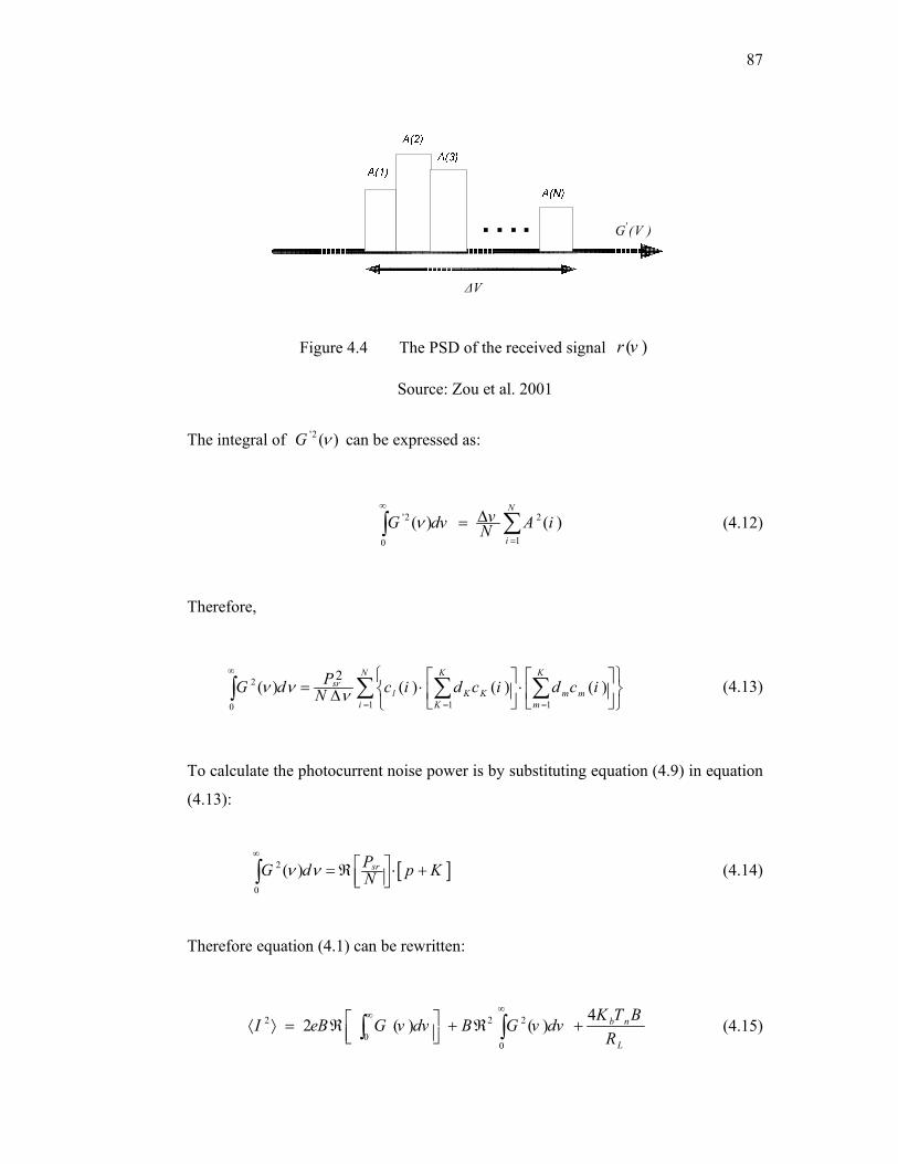
87
)V(G'
VΔ
Figure 4.4 The PSD of the received signal ( )r v
Source: Zou et al. 2001
The integral of '2 ( )G ν can be expressed as:
'2 2
10
( ) ( )N
i
vG dv A iNν∞
=
Δ= ∑∫ (4.12)
Therefore,
2
1 1 10
2( ) ( ) ( ) ( )
N K Ksr
l K K m mi K m
PG d c i d c i d c iNν ν ν
∞
= = =
⎧ ⎫⎡ ⎤ ⎡ ⎤= ⋅ ⋅⎨ ⎬⎢ ⎥ ⎢ ⎥Δ ⎣ ⎦ ⎣ ⎦⎩ ⎭∑ ∑ ∑∫ (4.13)
To calculate the photocurrent noise power is by substituting equation (4.9) in equation
(4.13):
[ ]2
0
( ) srPG d p KNν ν∞
⎡ ⎤= ℜ ⋅ +⎢ ⎥⎣ ⎦∫ (4.14)
Therefore equation (4.1) can be rewritten:
2 2 2
00
42 ( ) ( ) b n
L
K T BI eB G v dv B G v dvR
∞∞⎡ ⎤⟨ ⟩ = ℜ + ℜ +⎢ ⎥⎣ ⎦∫ ∫ (4.15)
88
2
2 2 42 ( ) ( )sr sr b n
L
P P K K T BI eB p K B p KN Np Rν
⟨ ⟩ = ℜ + + ℜ + +Δ
(4.16)
From equation (4.14) and equation (4.16), the average SNR can be obtained as:
2
2Data
Noise
ISNRI
= (4.17)
2
22
( )[ ]
42 ( ) ( )
sr
sr sr b n
L
P p KNSNR
P P K K T BeB p K B p KN Np Rν
+ℜ
=ℜ + + ℜ + +
Δ
(4.18)
Using Gaussian approximation, the Bit Error Rate (BER) can be expressed as:
1 ( )2 8eSNRBER P erfc= = (4.19)
where, erfc (.) is the complementary error function:
( ) (2 ) u
xerfc x e duπ
∞ −= ∫ (4.20)
Since the above analysis can be applied to any incoherent SAC optical CDMA,
the same process can be applied to the MDW code system. Here, we need to
determine the MDW code properties that are required for eavesdropper direct
detection scheme which is given by:
1
,( ) ( )
1,
N
K li
W K lc i c i
K l=
=⎧=⎨ ≠⎩
∑ (4.21)
89
In most SAC optical CDMA systems, when the data bit is “1,” a spectrally
encoded pulse is sent, while nothing is sent for data bit “0”. Noises that exist in such a
system include incoherent intensity noise, shot noise, as well as thermal noise. The
overall SNR of such systems is given in (Aljunid et al. 2004) as following:
( )( ) ( )
2 2 2
2
2 2
2
1 1 41 12
sr
sr B rsr
L
R PWNSNR
W K BR PWK K T BKeBRP W wN N W R
λλ
υ λ
=+ + −⎛ ⎞ ⎛ ⎞−⎛ ⎞+ + + − +⎜ ⎟ ⎜ ⎟⎜ ⎟Δ −⎝ ⎠ ⎝ ⎠⎝ ⎠
(4.22)
where R is the photodiode responsively, srP is the effective power of a broad-band
source at the receiver, e is an electron charge, B is the electrical equivalent noise
band-width of the receiver, BK is the Boltzmann’s constant, rT the absolute
temperature of receiver noise, LR the load resistance, vΔ the optical source
bandwidth, K the number of users, N the code length, W the weight, and λ the
cross-correlation.
Because intensity noise dominates and increasing the received optical power
cannot alleviate its effect, the signal to noise ratio (SNR) limit due to this noise is
considered in this analysis and can be expressed as:
2 1
22
W
SNRK KBK
υλ
λ
⎛ ⎞− Δ⎜ ⎟⎝ ⎠=⎡ ⎤+ −⎢ ⎥⎣ ⎦
(4.23)
Therefore, for a given value of spectral width vΔ ,B andK , the SNR depends
on W λ only. However, for DW and MDW codes, the cross correlation λ is always
minimized at λ =1, thus, the performance of DW and MDW codes depends on code
weight only, which is much easier to control. For example, if W = 4, the SNR will be
( )12
4SNR
BK KυΔ
=+
(4.24)
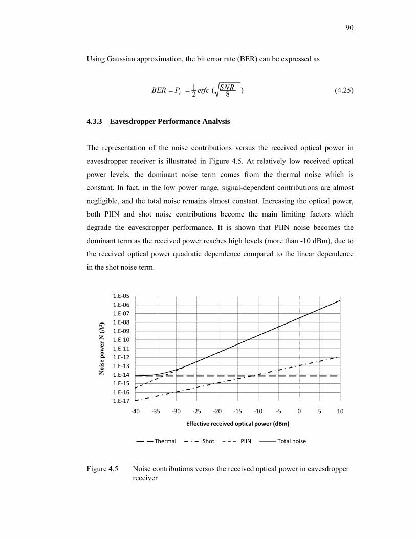
90
Using Gaussian approximation, the bit error rate (BER) can be expressed as
1 ( )2 8eSNRBER P erfc= = (4.25)
4.3.3 Eavesdropper Performance Analysis
The representation of the noise contributions versus the received optical power in
eavesdropper receiver is illustrated in Figure 4.5. At relatively low received optical
power levels, the dominant noise term comes from the thermal noise which is
constant. In fact, in the low power range, signal-dependent contributions are almost
negligible, and the total noise remains almost constant. Increasing the optical power,
both PIIN and shot noise contributions become the main limiting factors which
degrade the eavesdropper performance. It is shown that PIIN noise becomes the
dominant term as the received power reaches high levels (more than -10 dBm), due to
the received optical power quadratic dependence compared to the linear dependence
in the shot noise term.
Figure 4.5 Noise contributions versus the received optical power in eavesdropper receiver
1.E‐171.E‐161.E‐151.E‐141.E‐131.E‐121.E‐111.E‐101.E‐091.E‐081.E‐071.E‐061.E‐05
‐40 ‐35 ‐30 ‐25 ‐20 ‐15 ‐10 ‐5 0 5 10
Noi
se p
ower
N (A
2 )
Effective received optical power (dBm)
Thermal Shot PIIN Total noise
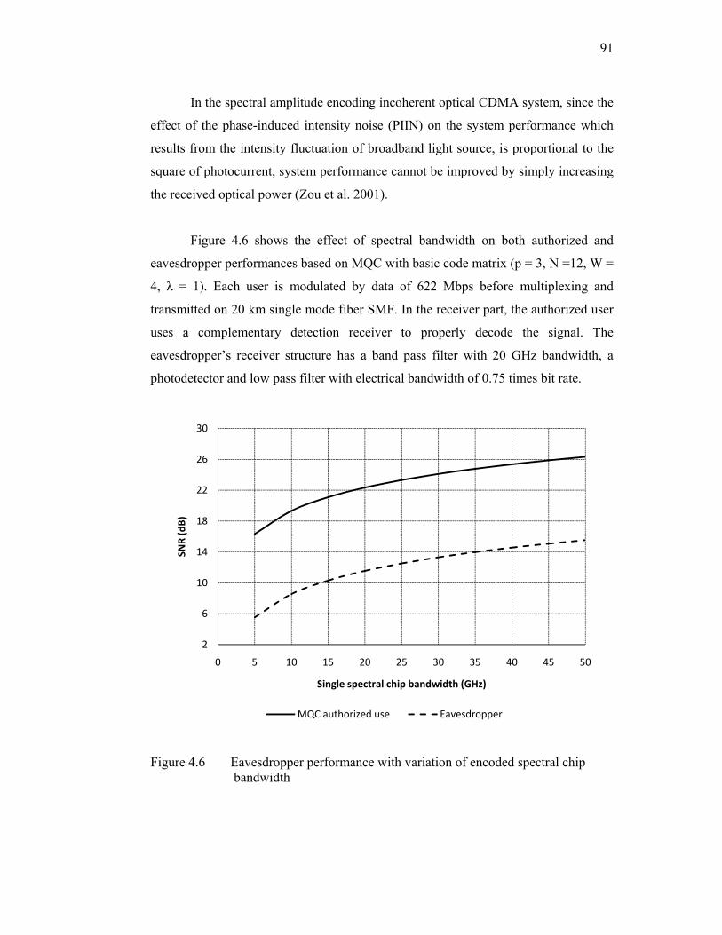
91
In the spectral amplitude encoding incoherent optical CDMA system, since the
effect of the phase-induced intensity noise (PIIN) on the system performance which
results from the intensity fluctuation of broadband light source, is proportional to the
square of photocurrent, system performance cannot be improved by simply increasing
the received optical power (Zou et al. 2001).
Figure 4.6 shows the effect of spectral bandwidth on both authorized and
eavesdropper performances based on MQC with basic code matrix (p = 3, N =12, W =
4, λ = 1). Each user is modulated by data of 622 Mbps before multiplexing and
transmitted on 20 km single mode fiber SMF. In the receiver part, the authorized user
uses a complementary detection receiver to properly decode the signal. The
eavesdropper’s receiver structure has a band pass filter with 20 GHz bandwidth, a
photodetector and low pass filter with electrical bandwidth of 0.75 times bit rate.
Figure 4.6 Eavesdropper performance with variation of encoded spectral chip bandwidth
2
6
10
14
18
22
26
30
0 5 10 15 20 25 30 35 40 45 50
SNR (dB)
Single spectral chip bandwidth (GHz)
MQC authorized use Eavesdropper

92
At encoded spectral chip of 20 GHz the detected SNRs are 22 dB and 12 dB
for authorized user and eavesdropper, respectively. These values are corresponding to
bit error rate BERs of nearly 10-11 and 10-3, respectively, as shown in Figure 4.7. In
optical communication systems, the maximum acceptable system BER is assumed to
be 10-9. Further decreasing in spectral chip bandwidth would force the authorized user
to use error correction codes used in commercial high-rate optical telecommunication
equipment that can maintain the acceptable BER.
Further security enhancement can be obtained by increasing the code
dimension as shown in Figure 4.8. With large value of prime number p, the main
parameter to construct MQC codes, the eavesdropper ability to detect single encoded
pulses becomes difficult even with wideband spectral chip. The eavesdropper BER
will be higher than 10-3.
Figure 4.7 Authorized user and eavesdropper BER performance
1.E‐16
1.E‐14
1.E‐12
1.E‐10
1.E‐08
1.E‐06
1.E‐04
1.E‐02
1.E+00
0 5 10 15 20 25 30 35 40 45 50
BER
Single spectral chip bandwidth (GHz)
MQC authorized user Eavesdropper
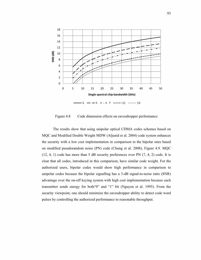
93
Figure 4.8 Code dimension effects on eavesdropper performance
The results show that using unipolar optical CDMA codes schemes based on
MQC and Modified Double Weight MDW (Aljunid et al. 2004) code system enhances
the security with a low cost implementation in comparison to the bipolar ones based
on modified pseudorandom noise (PN) code (Chung et al. 2008), Figure 4.9. MQC
(12, 4, 1) code has more than 5 dB security preferences over PN (7, 4, 2) code. It is
clear that all codes, introduced in this comparison, have similar code weight. For the
authorized users, bipolar codes would show high performance in comparison to
unipolar codes because the bipolar signalling has a 3-dB signal-to-noise ratio (SNR)
advantage over the on-off keying system with high cost implementation because each
transmitter sends energy for both“0” and “1” bit (Nguyen et al. 1995). From the
security viewpoint, one should minimize the eavesdropper ability to detect code word
pulses by controlling the authorized performance to reasonable throughput.
0
2
4
6
8
10
12
14
16
18
0 5 10 15 20 25 30 35 40 45 50
SNR (dB)
Single spectral chip bandwidth (GHz)
3 5 7 11 13

94
Figure 4.9 Eavesdropper performances for unipolar and bipolar optical CDMA codes
4.4 SIMULATION OF TRANSMISSION SECURITY PERFORMANCE FOR SAC OPTICAL CDMA SYSTEMS
Generally, the design and analysis of optical communication systems are growing in
complexity due to the usually contained non-Gaussian noise sources and nonlinear
devices. These systems are highly complicated and highly time-intensive. Therefore,
many computer softwares are commercially available to analyze the behaviour of a
present or proposed optical communication system. As a result, such systems can now
be carried out effectively and efficiently with the help of these modern computer
software tools.
In this work, we have used a powerful simulation software, OptiSystem
Version 7.0 from Optiwave (Optiwave 2007), to analyze the performance of the
eavesdropper for SAC optical CDMA systems in the physical layer. OptiSystem
enables the design automation of almost any type of optical link in the physical layer,
and the analysis of a broad spectrum of optical networks, from long-haul systems to
MANs and LANs (Optiwave 2007).
0
5
10
15
20
25
0 10 20 30 40 50
SNR (dB)
Single spectral chip bandwidth (GHz)
MDW(9,4,1) MQC (12,4,1) Bipolar PN (7,4,2)
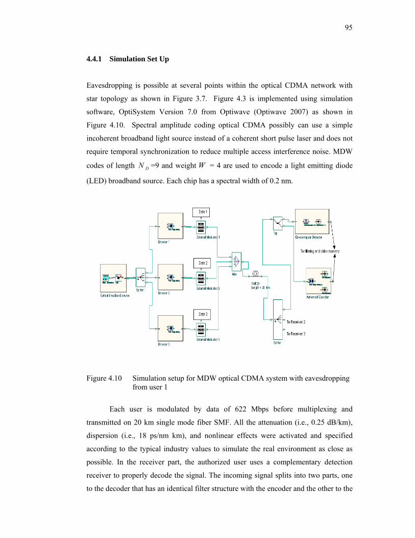
95
4.4.1 Simulation Set Up
Eavesdropping is possible at several points within the optical CDMA network with
star topology as shown in Figure 3.7. Figure 4.3 is implemented using simulation
software, OptiSystem Version 7.0 from Optiwave (Optiwave 2007) as shown in
Figure 4.10. Spectral amplitude coding optical CDMA possibly can use a simple
incoherent broadband light source instead of a coherent short pulse laser and does not
require temporal synchronization to reduce multiple access interference noise. MDW
codes of length DN =9 and weight W = 4 are used to encode a light emitting diode
(LED) broadband source. Each chip has a spectral width of 0.2 nm.
Figure 4.10 Simulation setup for MDW optical CDMA system with eavesdropping from user 1
Each user is modulated by data of 622 Mbps before multiplexing and
transmitted on 20 km single mode fiber SMF. All the attenuation (i.e., 0.25 dB/km),
dispersion (i.e., 18 ps/nm km), and nonlinear effects were activated and specified
according to the typical industry values to simulate the real environment as close as
possible. In the receiver part, the authorized user uses a complementary detection
receiver to properly decode the signal. The incoming signal splits into two parts, one
to the decoder that has an identical filter structure with the encoder and the other to the
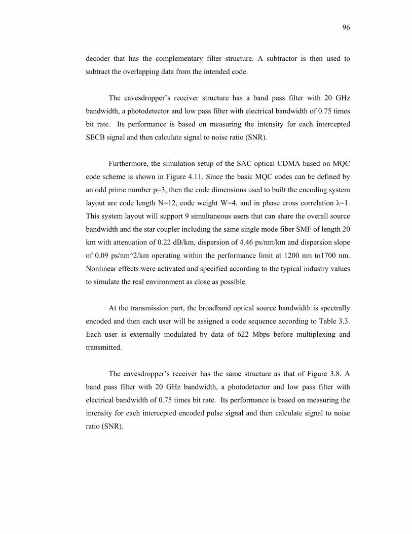
96
decoder that has the complementary filter structure. A subtractor is then used to
subtract the overlapping data from the intended code.
The eavesdropper’s receiver structure has a band pass filter with 20 GHz
bandwidth, a photodetector and low pass filter with electrical bandwidth of 0.75 times
bit rate. Its performance is based on measuring the intensity for each intercepted
SECB signal and then calculate signal to noise ratio (SNR).
Furthermore, the simulation setup of the SAC optical CDMA based on MQC
code scheme is shown in Figure 4.11. Since the basic MQC codes can be defined by
an odd prime number p=3, then the code dimensions used to built the encoding system
layout are code length N=12, code weight W=4, and in phase cross correlation λ=1.
This system layout will support 9 simultaneous users that can share the overall source
bandwidth and the star coupler including the same single mode fiber SMF of length 20
km with attenuation of 0.22 dB/km, dispersion of 4.46 ps/nm/km and dispersion slope
of 0.09 ps/nm^2/km operating within the performance limit at 1200 nm to1700 nm.
Nonlinear effects were activated and specified according to the typical industry values
to simulate the real environment as close as possible.
At the transmission part, the broadband optical source bandwidth is spectrally
encoded and then each user will be assigned a code sequence according to Table 3.3.
Each user is externally modulated by data of 622 Mbps before multiplexing and
transmitted.
The eavesdropper’s receiver has the same structure as that of Figure 3.8. A
band pass filter with 20 GHz bandwidth, a photodetector and low pass filter with
electrical bandwidth of 0.75 times bit rate. Its performance is based on measuring the
intensity for each intercepted encoded pulse signal and then calculate signal to noise
ratio (SNR).
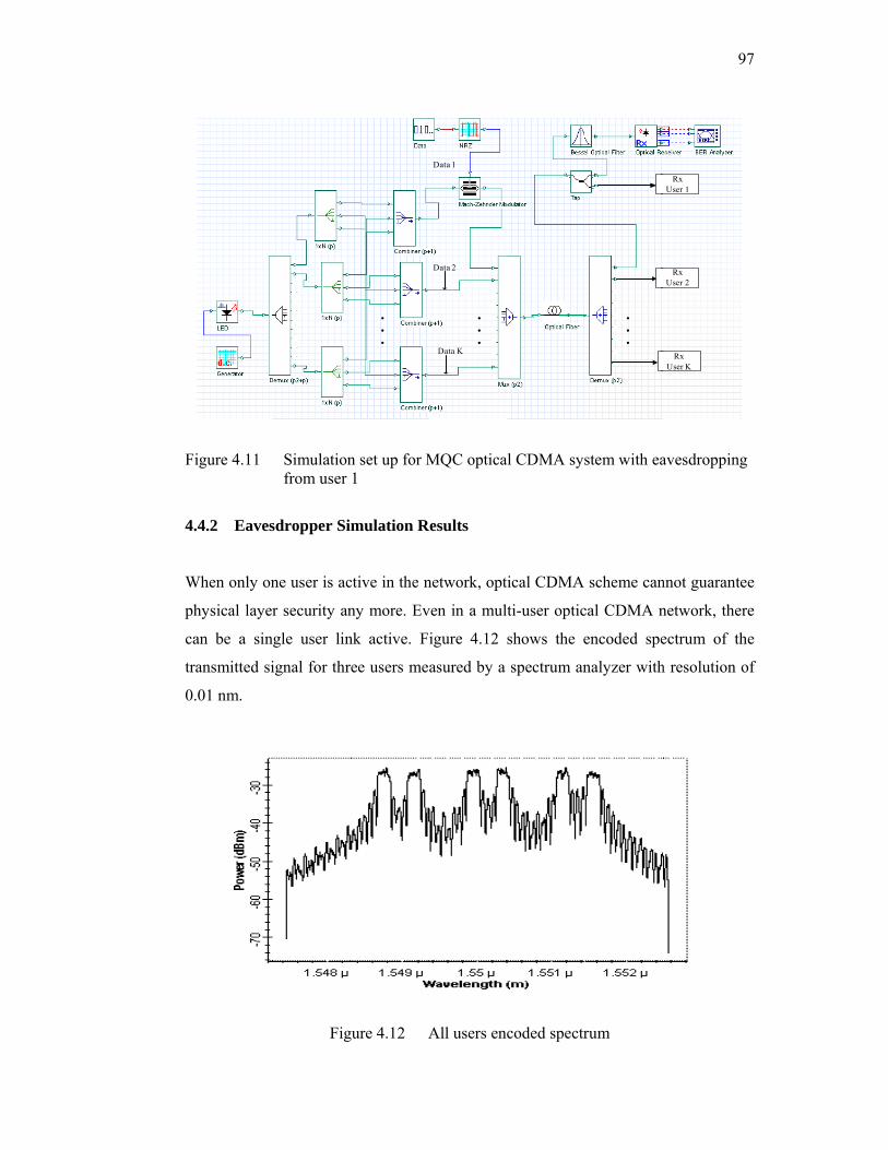
F
4.
W
ph
ca
tr
0
igure 4.11
.4.2 Eaves
When only on
hysical laye
an be a sin
ransmitted si
.01 nm.
Simulationfrom user
sdropper Si
ne user is ac
r security an
ngle user lin
ignal for thr
Fig
n set up for M1
mulation R
ctive in the n
ny more. Ev
nk active. F
ree users me
gure 4.12 A
Data 2
Data K
Data 1
MQC optica
Results
network, opt
ven in a mul
igure 4.12
asured by a
All users en
al CDMA sys
tical CDMA
lti-user optic
shows the e
spectrum an
coded spectr
stem with ea
scheme can
cal CDMA n
encoded spe
nalyzer with
rum
9
RxUser 1
RxUser 2
RxUser K
avesdropping
nnot guarante
network, the
ectrum of th
h resolution
97
g
ee
ere
he
of

98
An eavesdropper may intercept and extract information data by tuning a
narrow band pass filter across the entire wavelength range and select one spectral chip
as shown in Figure 3.8. In this case, an eavesdropper has the information about the
spectral bandwidth of one spectral chip and the type of the encoding system being
used and does not know the code word itself.
Figure 4.13 All users encoded spectrum detected by eavesdropper
Each detected pulse represents a double weight spectral intensity; so, Figure
4.13 indicates there are 6 of them in the entire spectral bandwidth used for this
particular transmission. Figure 4.14 shows the spectral chips, detected by the
eavesdropper, for an isolated user (user 1) when the others are not active. Each pulse
has a double weight chip which is satisfied with the code dimension MDW (9, 4, 1)
being used in this analysis. The effective power of the broadband source at the
eavesdropper photodetector is measured to be -33 dBm for each single spectral chip
pulse.
Figure 4.15 shows the effects of ESCB on authorized user and eavesdropper
receiver represented by dashed and solid lines respectively. Their corresponding
simulation results are given by the triangle and rectangle symbols respectively. The
4
6
8
10
12
14
16
18
1548
1548
.5
1549
1549
.5
1550
1550
.5
1551
1551
.5
1552
SNR (dB)
Spectral wavelengths (nm)
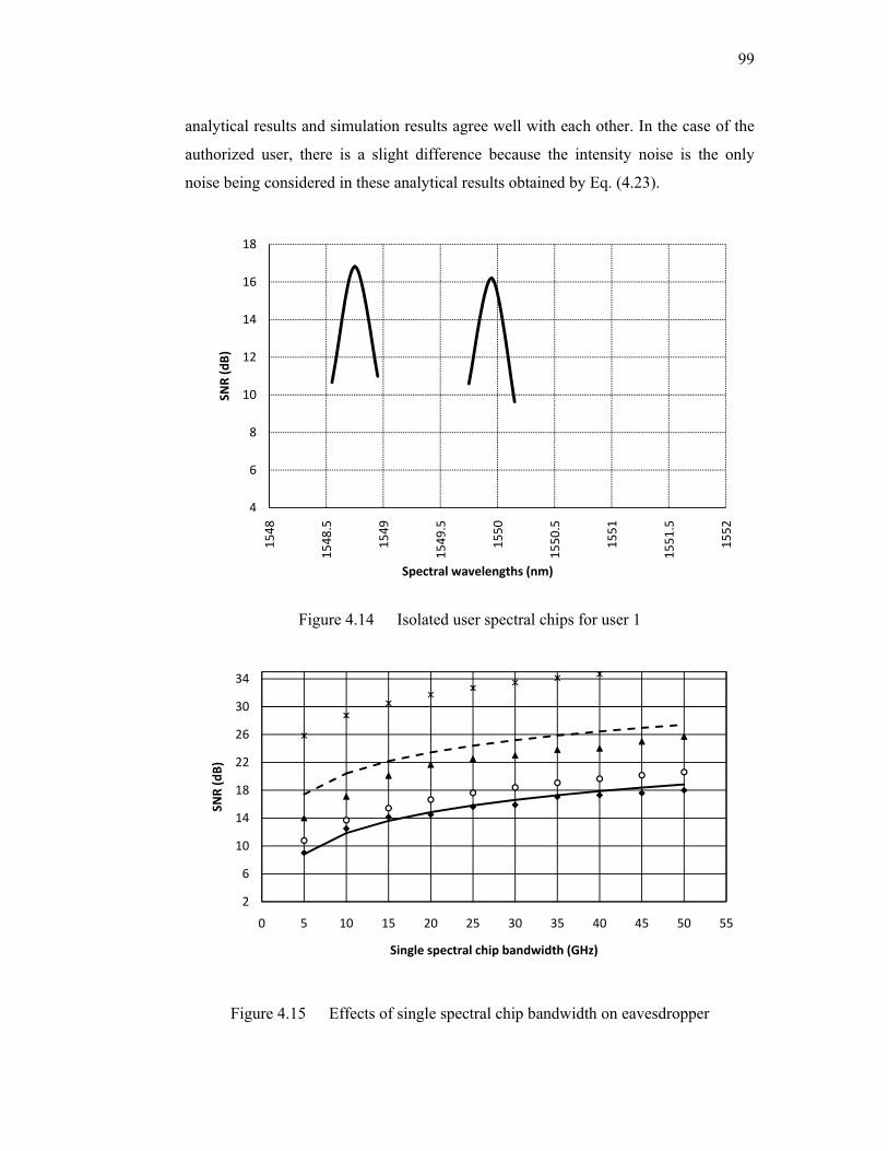
99
analytical results and simulation results agree well with each other. In the case of the
authorized user, there is a slight difference because the intensity noise is the only
noise being considered in these analytical results obtained by Eq. (4.23).
Figure 4.14 Isolated user spectral chips for user 1
Figure 4.15 Effects of single spectral chip bandwidth on eavesdropper
4
6
8
10
12
14
16
18
1548
1548
.5
1549
1549
.5
1550
1550
.5
1551
1551
.5
1552
SNR (dB)
Spectral wavelengths (nm)
2
6
10
14
18
22
26
30
34
0 5 10 15 20 25 30 35 40 45 50 55
SNR (dB)
Single spectral chip bandwidth (GHz)
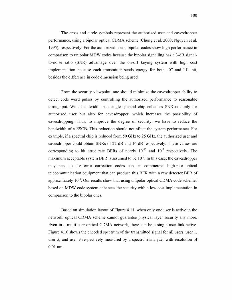
100
The cross and circle symbols represent the authorized user and eavesdropper
performance, using a bipolar optical CDMA scheme (Chung et al. 2008; Nguyen et al.
1995), respectively. For the authorized users, bipolar codes show high performance in
comparison to unipolar MDW codes because the bipolar signalling has a 3-dB signal-
to-noise ratio (SNR) advantage over the on-off keying system with high cost
implementation because each transmitter sends energy for both “0” and “1” bit,
besides the difference in code dimension being used.
From the security viewpoint, one should minimize the eavesdropper ability to
detect code word pulses by controlling the authorized performance to reasonable
throughput. Wide bandwidth in a single spectral chip enhances SNR not only for
authorized user but also for eavesdropper, which increases the possibility of
eavesdropping. Thus, to improve the degree of security, we have to reduce the
bandwidth of a ESCB. This reduction should not affect the system performance. For
example, if a spectral chip is reduced from 50 GHz to 25 GHz, the authorized user and
eavesdropper could obtain SNRs of 22 dB and 16 dB respectively. These values are
corresponding to bit error rate BERs of nearly 10-12 and 10-5 respectively. The
maximum acceptable system BER is assumed to be 10-9. In this case; the eavesdropper
may need to use error correction codes used in commercial high-rate optical
telecommunication equipment that can produce this BER with a raw detector BER of
approximately 10-4. Our results show that using unipolar optical CDMA code schemes
based on MDW code system enhances the security with a low cost implementation in
comparison to the bipolar ones.
Based on simulation layout of Figure 4.11, when only one user is active in the
network, optical CDMA scheme cannot guarantee physical layer security any more.
Even in a multi user optical CDMA network, there can be a single user link active.
Figure 4.16 shows the encoded spectrum of the transmitted signal for all users, user 1,
user 5, and user 9 respectively measured by a spectrum analyzer with resolution of
0.01 nm.

101
Figure 4.16 Encoded spectrum detected by eavesdropper: (a) all users, (b) user 1, (c) user 5 and (d) user 9
An eavesdropper may intercept and extract information data by tuning a band
pass filter across the entire wavelength range and select one spectral chip. In this case,
an eavesdropper had the information about the spectral bandwidth of one spectral chip
and the type of the encoding system being used and didn’t know the code word itself.
Figure 4.17 shows the encoded spectral chips, detected by the eavesdropper, for an
isolated user (user 1) when the others are not active, which is matching the code
sequence for user 1 (Zou et al. 2001). The effective power of the broadband source at
the front of eavesdropper photodetector is measured to be -30 dBm for each single
spectral chip pulse and its corresponding average SNR is calculated to be nearly 10
dB. This SNR value gives the eavesdropper capability to intercept encoded pulse chip
with a probability of correct detection of 0.7 as shown in Figure 4.2. In fact this is
only true for MQC codes when p = 3. For other code dimensions, p = 7, 11, and 13, 10
dB would be only enough to intercept code pulses with probability of correct detection
= 0.4, 0.2, and 0.1 respectively. Thus, increasing code size will force eavesdropper to
get low code pulse SNRs with low probability of correct detection.
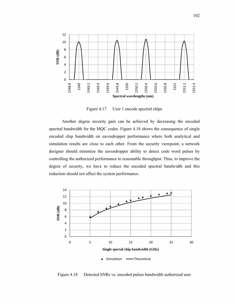
102
Figure 4.17 User 1 encode spectral chips
Another degree security gain can be achieved by decreasing the encoded
spectral bandwidth for the MQC codes. Figure 4.18 shows the consequence of single
encoded chip bandwidth on eavesdropper performance where both analytical and
simulation results are close to each other. From the security viewpoint, a network
designer should minimize the eavesdropper ability to detect code word pulses by
controlling the authorized performance to reasonable throughput. Thus, to improve the
degree of security, we have to reduce the encoded spectral bandwidth and this
reduction should not affect the system performance.
Figure 4.18 Detected SNRs vs. encoded pulses bandwidth authorized user
0
2
4
6
8
10
12
1548
.8
1549
1549
.2
1549
.4
1549
.6
1549
.8
1550
1550
.2
1550
.4
1550
.6
1550
.8
1551
1551
.2
1551
.4
SNR
(dB
)
Spectral wavelengths (nm)
0
2
4
6
8
10
12
14
0 5 10 15 20 25 30
SNR
(dB
)
Single spectal chip bandwidth (GHz)
Simulation Theoretical

103
4.5 SUMMARY
This chapter presented and discussed the transmission security performance results of
SAC optical CDMA. We have applied MDW and MQC codes to demonstrate the
eavesdropper performance. The results showed that increasing the code size will force
eavesdropper to acquire encode code pulses with low SNRs. Therefore, a low
probability of correct detection is achieved. Moreover, wide bandwidth in a single
spectral chip enhances the achieved SNR, not only for authorized user but also for an
eavesdropper, which increases the possibility of eavesdropping. Thus, to improve the
degree of security, we have to reduce the encoding spectral chip bandwidth (ESCB).
From the security viewpoint, one should minimize the eavesdropper ability to detect
code word pulses by controlling the authorized performance to reasonable throughput.
Our results showed that using unipolar optical CDMA codes schemes based on
MQC and MDW code systems enhanced the security with a low cost implementation
in comparison to the bipolar ones based on modified pseudorandom noise (PN) code.
Furthermore, both analytical and simulation results are close to each other.
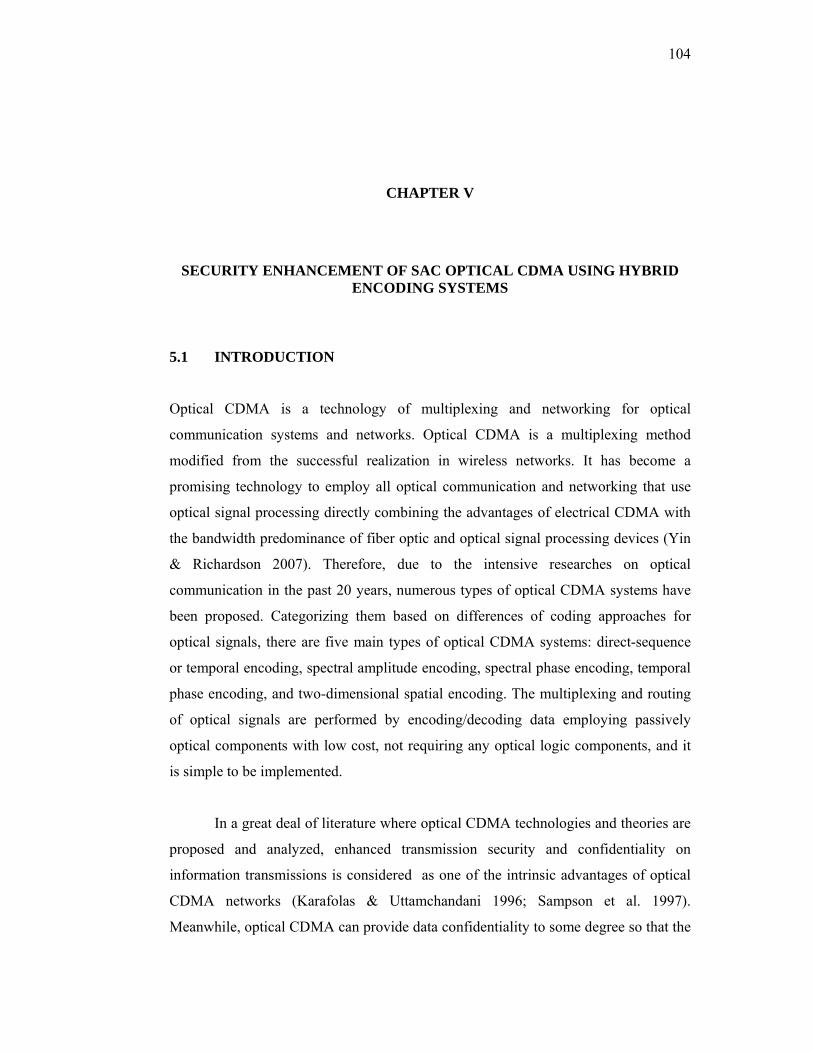
104
CHAPTER V
SECURITY ENHANCEMENT OF SAC OPTICAL CDMA USING HYBRID ENCODING SYSTEMS
5.1 INTRODUCTION
Optical CDMA is a technology of multiplexing and networking for optical
communication systems and networks. Optical CDMA is a multiplexing method
modified from the successful realization in wireless networks. It has become a
promising technology to employ all optical communication and networking that use
optical signal processing directly combining the advantages of electrical CDMA with
the bandwidth predominance of fiber optic and optical signal processing devices (Yin
& Richardson 2007). Therefore, due to the intensive researches on optical
communication in the past 20 years, numerous types of optical CDMA systems have
been proposed. Categorizing them based on differences of coding approaches for
optical signals, there are five main types of optical CDMA systems: direct-sequence
or temporal encoding, spectral amplitude encoding, spectral phase encoding, temporal
phase encoding, and two-dimensional spatial encoding. The multiplexing and routing
of optical signals are performed by encoding/decoding data employing passively
optical components with low cost, not requiring any optical logic components, and it
is simple to be implemented.
In a great deal of literature where optical CDMA technologies and theories are
proposed and analyzed, enhanced transmission security and confidentiality on
information transmissions is considered as one of the intrinsic advantages of optical
CDMA networks (Karafolas & Uttamchandani 1996; Sampson et al. 1997).
Meanwhile, optical CDMA can provide data confidentiality to some degree so that the
105
private requirements of routine and business services from different subscribers can be
satisfied.
The quantitative analysis of data confidentiality has been performed for optical
CDMA techniques that employ 2-D wavelength-hopping/time-spreading encoding
(Shake 2005b) and spectral phase encoding (Shake 2005a). Furthermore, the degree of
confidentiality provided is highly dependent on system design and implementation
parameters, such as code space size, data modulation approach (Leaird et al. 2005;
Qin et al. 2008), system signal-to-noise ratio, fraction of total available system
capacity and so on.
In this chapter, we have presented security enhancement for spectral amplitude
coding (SAC) optical CDMA using hybrid SAC schemes. One dimension hybrid
(ODH) EDW/m-sequence and two dimensions (2D) EDW/m-sequence code systems
have been implemented to provide a degree of transmission security for SAC optical
CDMA. Each user will assign a hybrid code signature based on combining and
integrating the properties for both m-sequence and EDW codes. The eavesdropper
here will employ the same strategy that has been discussed in Chapter III. The
eavesdropper’s target is to detect the presence of the authorized user’s transmission
and attempt to recognize his encoded spectral chip of the code word. Therefore, the
eavesdropper will tap a coded transmission of a particular user and performs the
necessary calculations to derive the transmitter’s code word from these transmissions.
Furthermore, we have simulated these hybrid SAC optical CDMA systems using
Optisystem software version 7 to present eavesdropper performance.
5.2 CONVENTIONAL SPECTRAL AMPLITUDE CODING OPTICAL CDMA SYSTEMS
Many types of optical CDMA systems have been proposed as the result of intensive
research on optical CDMA in the past 20 years. If we classify them in terms of the
nature of the superposition of the optical signal, they can be divided into coherent
optical CDMA systems and incoherent optical CDMA systems (Yin & Richardson
2007).
106
The coherent optical CDMA system makes use of the coherent property of
light and implements bipolar encoding of the optical signal, i.e., encoding the phase of
optical signals, with the phase of light detected at the receiving terminals. The form of
signal addition is the superposition of light signal amplitudes. These bipolar codes
encompass m-sequences, Gold codes, and Walsh-Hadamard codes (Cao & Qian 1992;
Prucnal 2006). This kind of Optical CDMA systems need to use ultra short broadband
light pulse sources.
The incoherent optical CDMA system employs the presence of light signal or
absence of light signal to represent the binary “1” and “0” respectively, which is
unipolar encoding, where the light signals are detected with the square-law devices at
the receiving terminals. This form of signal addition is the superposition of light
powers. This kind of optical CDMA system may use incoherent light sources, such as
amplified spontaneous emission (ASE) or light-emitting diode (LED) (Salehi 1989;
Zou et al. 2001).
In recent years, spectral-amplitude coding (SAC) scheme has become more
noticeable in the research of incoherent optical CDMA network systems because of its
unique ability for the cancellation of multiple-access interference (MAI). A code that
can be used in such kind of network system is denoted as (N, W, λ), where N is code
length, W is code weight, and λ is the correlation bound of the code.
5.2.1 M-sequence Codes
The most common spreading sequences used in wireless communications are known
as maximal length sequences (m-sequence). It is a pseudorandom sequence which can
be simply generated by the feedback-shift-registers and has the maximal period
(Peterson et al. 1995). Therefore, it is called the maximal linear feedback-shift-register
sequence. The period of m-sequence code is not only associated with the number of
stages of shift-registers, but is also related to the linear feedback logic. A linear
feedback shift register of length r produces an m-sequence if and only if the
corresponding generated polynomial of degree r is primitive (Schulze & Lueders
2005). Therefore, when r stage shift-register is employed, the period of the m-
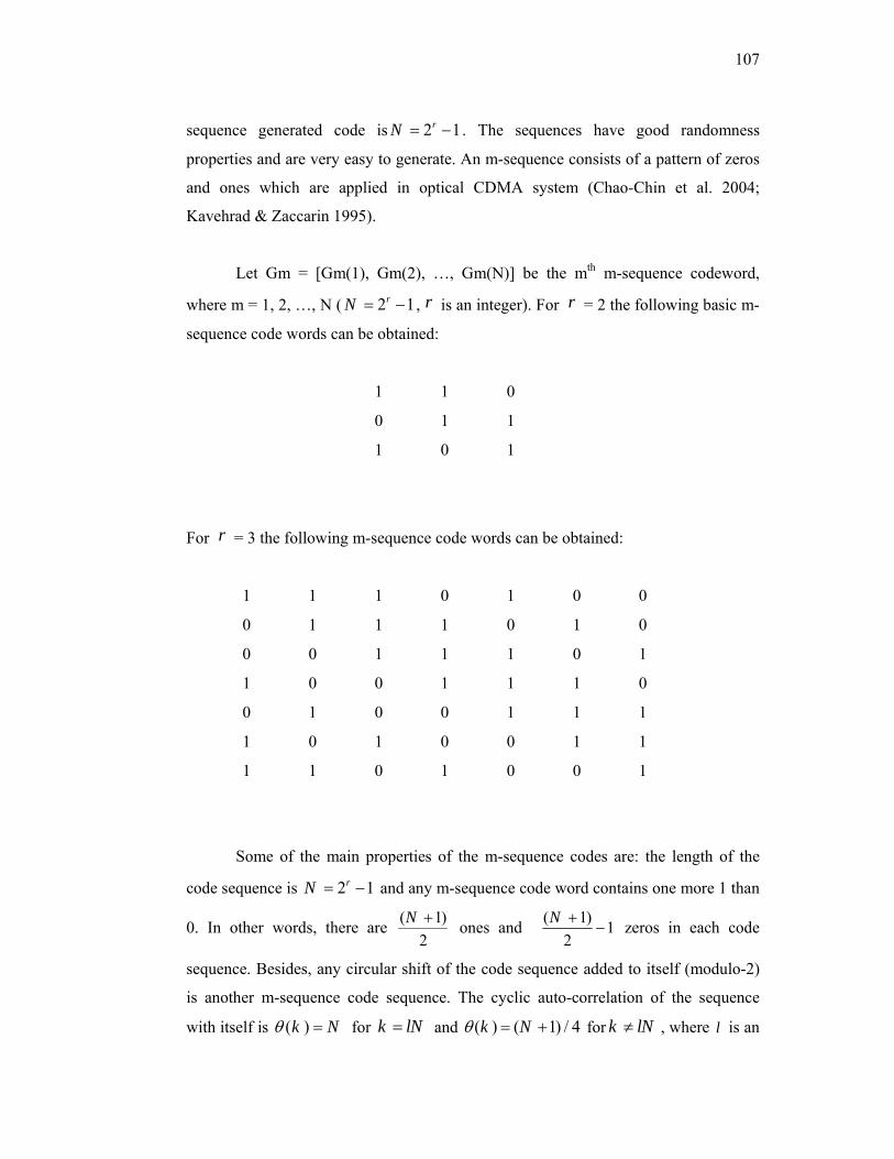
107
sequence generated code is 2 1rN = − . The sequences have good randomness
properties and are very easy to generate. An m-sequence consists of a pattern of zeros
and ones which are applied in optical CDMA system (Chao-Chin et al. 2004;
Kavehrad & Zaccarin 1995).
Let Gm = [Gm(1), Gm(2), …, Gm(N)] be the mth m-sequence codeword,
where m = 1, 2, …, N ( 2 1rN = − , r is an integer). For r = 2 the following basic m-
sequence code words can be obtained:
1 1 0
0 1 1
1 0 1
For r = 3 the following m-sequence code words can be obtained:
1 1 1 0 1 0 0
0 1 1 1 0 1 0
0 0 1 1 1 0 1
1 0 0 1 1 1 0
0 1 0 0 1 1 1
1 0 1 0 0 1 1
1 1 0 1 0 0 1
Some of the main properties of the m-sequence codes are: the length of the
code sequence is 2 1rN = − and any m-sequence code word contains one more 1 than
0. In other words, there are ( 1)2
N + ones and ( 1) 12
N +− zeros in each code
sequence. Besides, any circular shift of the code sequence added to itself (modulo-2)
is another m-sequence code sequence. The cyclic auto-correlation of the sequence
with itself is ( )k Nθ = for k lN= and ( ) ( 1) / 4k Nθ = + for k lN≠ , where l is an

108
integer. The cross-correlation for arbitrary two code sequences in the same family is
( 1)4
N +
5.2.2 Enhanced Double Weight (EDW)
Enhanced Double Weight EDW (Hasoon et al. 2007a) is the enhanced version of
Double Weight (DW) (Aljunid et al. 2004) code. The MDW code weight can be any
even number that is greater than two while the enhanced double weight EDW code
weight can be any odd number greater than one. Both complementary and direct
detection techniques have been implemented for authorized user detection (Abdullah
et al. 2008; Hasoon et al. 2007b). The spectral direct detection (SDD) technique has
shown better performance in comparison with the complementary one. In this chapter,
the EDW with the weight of three is used as an example.
EDW code can be represented by using K x N matrix. In EDW codes
structures, the matrix K rows and N columns represent the number of users and the
minimum code length respectively. A basic EDW code is given by a 3 x 6 matrix, as
shown in Table 5.1.
Table 5.1 The basic EDW code denoted by (6,3, 1)
C1 C2 C3 C4 C5 C6
User1 1 1 0 1 0 0
User2 0 1 0 0 1 1
User3 0 0 1 1 0 1
From the basic matrix, a larger number of K can be achieved by using a
mapping technique. EDW codes have the following properties: ideal maximum cross-
correlation max 1λ = , EDW code weight, which can be any odd number greater than one,
the weight pair structure maintained, the chip combination is maintained 1, 2, 1 for
every consecutive pairs of codes, and the relation between the number of users K and
code length N at weight of 3 is given by:
109
2 2 24 8 ( 1) 4 ( 2)2 sin( ) sin sin3 3 3 3 3 3
K K KN K π π π+ +⎡ ⎤ ⎡ ⎤ ⎡ ⎤= + +⎢ ⎥ ⎢ ⎥ ⎢ ⎥⎣ ⎦ ⎣ ⎦ ⎣ ⎦ (5.1)
5.3 2-D HYBRID EDW/M-SEQUENCE
Hybrid encoding approach, based on SAC optical CDMA systems, is introduced. This
type of encoding scheme uses a combination of the encoding approaches mentioned in
Chapter II. Therefore, combining and integrating the above mentioned properties for
both m-sequence and EDW codes, a hybrid code scheme can be obtained. The 2-D
hybrid scheme is based on spatial and frequency encoding and decoding process. Each
user will assign a hybrid code signature where, first the optical pulses will be encoded
in the frequency domain using EDW scheme and then spatially encoded using m-
sequence scheme.
5.3.1 Code Design
The encoding scheme is based on spatial and frequency encoding and decoding
process. The hybrid EDW/m-sequence codes are constructed as follow. Let Xi= [xi(1),
xi(2), …, xi(E)] be the ith EDW code word used in the spectral domain, where E
represents the code length; and Yj= [yj(1), yj(2), …, yj(N)] be the jth m-sequence
codeword used in the spatial domain, where j = 1, 2, …, N (where N = 2r-1, r is an
integer). Therefore, the optical hybrid EDW/m-sequence code assigned to user (i, j) in
the spectral/spatial optical CDMA system can be obtained from these two code words
by Hi,j = Xi T Yj (Yang et al. 2007). Thus, there are totally E N× code matrices
supported by the hybrid system as illustrated in Figure 5.1.
The 2D hybrid EDW/m-sequence optical CDMA block diagram is shown in
Figure 5.2. The network includes C encoders, C decoders, and N C C× star couplers.
User (i, j) is assigned with a specific hybrid EDW/m-sequence codeword Hi,j. The
incoming information bits of each user are encoded optically with the corresponding
matrix Hi,j by the associated encoder and distributed to each decoder through the star
couplers. Each user in the receiver end uses a decoder to recover the desired
information bits.

110
Figure 5.1 Code matrices of the 2-D hybrid EDW/m-sequence optical CDMA for E=6 and N=3
Figure 5.2 Block diagram of the 2D hybrid EDW/m-sequence optical CDMA
These hybrid codes are expected to increase the degree of security compared to
one dimensional code because the code size will increase. Besides, the complexity for
encoding and decoding will make the eavesdropper ability more difficult to physically
tap and intercept the correct code.
In spectral amplitude coding optical CDMA schemes, most contribution of
noise comes from thermal noise, shot noise and PIIN (Smith et al. 1998; Wei et al.

111
2001). The eavesdropper photocurrent variance resulting from the use of a band
limited photodetector as shown in Figure 3.8 (Chapter III) can be expressed as:
2
2 22
42 ( 2( 2)) ( 2( 2))2 . ( 1)
sr sr b n
L
P P KW K T BI eB W K B W KN V N W R
= ℜ + − + ℜ + − +Δ −
(5.2)
Applying the code properties for these codes, the signal to noise ratio (SNR)
limit due to incoherent intensity noise (Smith et al. 1998), is considered. Figure 5.3
shows the bit-error rate (BER) versus number of users when M.sequence, EDW and
hybrid EDW/m-sequence codes are used. In this figure we have used the following
parameters: optical bandwidth νΔ = 3.75 THz, receiver electrical bandwidth
B=311MHz (for bit rate 622Mbps) at the operation wavelength of 1550nm. It clearly
shows that this hybrid EDW/m-sequence code can support more users.
Figure 5.3 BER versus active users
1.E‐20
1.E‐18
1.E‐16
1.E‐14
1.E‐12
1.E‐10
1.E‐08
1.E‐06
1.E‐04
1.E‐02
0 5 10 15 20 25 30 35 40 45 50
BER
Number of active users
M.seq. EDW Hybrid M.seq./EDW

112
5.3.2 Security Performance
An intelligent eavesdropper can design a listening device to detect this code word as
shown in Figure 5.4. Once a user’s code word is detected by the eavesdropper, the
eavesdropper has free access to the user’s data until the user’s code is changed.
Figure 5.4 Eavesdropper code interceptor structure
If the code interceptor makes a code word decision based on observing the
transmitted signal for encoded spectral amplitude coding optical CDMA data bit
interval, the overall probability of correct code pulse detection is given by Eq. (3.1)
from Chapter III:
( )(1 ) (1 )W N W
correct M FP P P −= − − (5.3)
Then, applying the code properties of the 2D hybrid EDW/m-sequence in
equation (5.3) we get:
.
.
.
1( )
2
1( ) ( )
2
1( 1 )
2
[ ( 2 / , ( 2 ) ] *
[1 e x p ( ) ] *
[1 e x p ( ) ]
m s e qe d w
m s e qe d we d w
m s e qe d w
NW
c o rre c t o o
NN W
oN
N
o
P Q E N N
N
N
γ
γ
γ
+
+−
+−
=
− −
− −
(5.4)
where / oE N is the single pulse signal to noise ratio and γ is detection threshold.
edwW and edwN is EDW code weight and cod length respectively. . .m seqN represents
m-sequence code length. These system design and operation parameters are the key
points for the degree of security enhancement provided by optical CDMA. This

113
enhancement is greatly dependent on the intercepted encoded pulse SNR. Q is a
function commonly called Marcum’s Q function:
2 2
0( , ) exp( ) ( )2
zQ z I z dzβ
αα β α∞ +
≅ −∫ (5.5)
If an eavesdropper could be forced to tap code pulses with low SNRs, a
security enhancement can be obtained as shown in Figure 5.5. An eavesdropper would
need SNR of 9.2 dB to correctly detect encoded pulses with a probability of 50 % for
the hybrid scheme, while he needs 4.2 dB and 6.8 dB for m-sequence and EDW
schemes respectively. The hybrid scheme provides security improvement of
approximately 50 % and 75 % for m-sequence and EDW schemes respectively. The
difference in performance of the eavesdropper’s receiver with envelope detection is
getting small, especially at higher SNRs. Approximately, at 14 dB; the eavesdropper
could tap encoded pulses with a probability of virtually one.
Figure 5.5 Code intercepting detector performances using optical matched filter with envelope detection
0
0.1
0.2
0.3
0.4
0.5
0.6
0.7
0.8
0.9
1
2 4 6 8 10 12 14 16
Prob
. of c
orre
ct c
ode
puls
e de
tect
ion
SNR (dB)
M.seq. EDW Hybrid EDW/M.seq

114
5.4 ONE DIMENSION HYBRID (ODH) EDW/M-SEQUENCE SYSTEM
Another hybrid encoding approach, based on SAC optical CDMA systems, is
established. This type of encoding scheme uses a combination of the encoding
approaches mentioned in Chapter II. Once again, combining and integrating the above
mentioned properties for both m-sequence and EDW codes, a one dimension hybrid
(ODH) code scheme can be obtained. The hybrid code will add encoding complexity
for special authorized users which will make the eavesdropper code word interception
more complicated due to the code size expansion (Shake 2005b).
5.4.1 Code Design
Since the traditional generation method of m-sequence code is not systematic enough,
we have proposed new method for generating m-sequence systematically. The new
method will allow us to generate the code for any number of (r), which is considered
important for increasing the security of the system by increasing the code space size.
This new generation method will ease the construction of ODH mathematical model,
and make it more convenient.
The main control parameters in m-sequence construction are number of stages
(r), code length N, code weight (number of 1’s), number of 0’s, the code cross
correlation. These main parameters will determine if the code sequence meet its
properties or not. The following steps explain the algorithm design procedure used to
generate the code systematically. These steps are divided into two parts, which are
independent from each other, as stated below:
Part A: for r 2, 3= we have the following steps:
1- The basic sequence is started by adding 1’s equal to number of stages (r). For
r 2= , we have (11).
2- Match the number of 1’s with the code weight value, if equal then stop adding
1’s and start adding only 0’s.
115
3- For r 3= , in order to maintain cross correlation without change, we use (01)
sequences.
4- Since the first user sequence for r 2= is (110) and for r 3= is (1110100),
the subsequent users are generated using a circular shift of the previous user
sequence.
Part B: for ( r 4≥ )
1- For r = 4,we recall step 1from part A, and we add the following sequence:
(01011001).
2- For the rest code sequences we recall step 2 from part A. Therefore the first
user sequence is: (111101011001000).
3- The subsequent users are generated using a circular shift of the previous user
sequence.
4- For r 4> codes we use repeating of r = 4first user sequence until we fulfil step
2 of part A condition. E.g. for r = 5 the first user sequence is:
(1111010110010001111010110010000).
5- We repeat step3 in order to generate the full code.
The mathematical representations to the above generation steps are: let r =
number of stages{ }2, 3… , code length 2 1rN = − , number of 1’s (code weight)
12
NW += , number of 0’s 0'
1 12s
NW += − , and cross correlation 1
4Nλ +
= .
Assuming Basic sequence (B)
Br=2 = 11, Br=3= 111
Z= accumulation of zeros
if r = 2
1’st user sequence [110]
If r=3
1’st user sequence [1110100]
for r = 4, we use E=[01011001]
1’st user [111101011001000] (also used as reference code for larger r’s)
Noloop= (2) (r – 4) for r ≥ 4

116
Where NoLoop Determine the number of loops necessary to generate r>4 codes.
Assuming that M is the basic code matrix for r ≥ 4
Therefore M= [111101011001000]
Let MF is the final accumulated matrix of the code without Z, therefore the
accumulated repeat of the 1st user M.sequence code for r ≥ 4 can be given as below:
1
( )loopsNo
Fj
M M=
+∑ (5.6)
The final accumulated matrix of the code with Z: 0 ' 0 ' 4( * )
1
[ ] 0s s r loopsW W No
j
Z Z j→ =−
=
= =∑ (5.7)
The final 1st user matrix for r ≥ 4 is:
0 ' 0 ' 4( * )
1 1( ) [ ] 0
s s r loopsloops W W NoNo
Fj j
X M M Z j→ =−
= =
= + + =∑ ∑ (5.8)
Applying step 3 from Part B to generate the subsequent user matrices using circulate
shift
By assuming R=X, Y=X
R [1] =Y [N]
Apply on previous user to generate subsequent user sequence using the Eq. Below:
( ) ( )1
11
N
iR R i Y i
−
=
= + =∑ (5.9)
For full code generation we use the following steps:
Step 1:
First element substitution

117
1( ,1) ( , )
N
iX i Y i N
=
=∑ (5.10)
Step 2:
Making the row number constant.
k=i
Step 3:
Rest elements shift
( ) ( )1
1
, 1 ,N
j
X k j Y k j−
=
+ =∑ (5.11)
Step4:
Go to step 1 until No. of users are achieved.
The ODH codes are constructed by multiplying the m-sequence code matrix with each
of EDW matrix elements. (The EDW generation method) is shown below :
X=EDW matrix
S=W
Where W is the code weight
Assuming y=X
( ) ( )1
[ 1, , ].[ .].s
iX i y w i M seq
=
= −∑ (5.12)
( ) ( )1 1
[ 1, , ].[ .].s s
i j
X j i y j i M seq= =
+ = −∑∑ (5.13)
The hybrid EDW/m-sequence codes are constructed by substituting the m-
sequence code matrix with each one of EDW code matrixes. When r = 2, the basic
matrix for m-sequence can be rewritten as shown below.
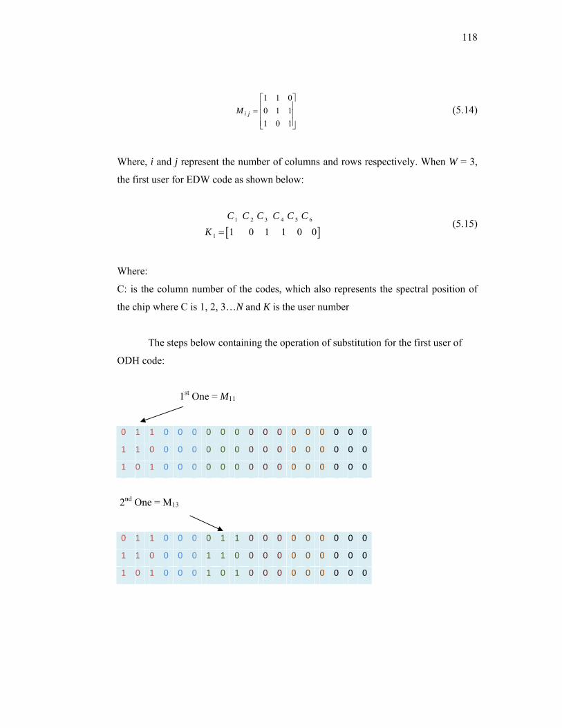
118
⎥⎥⎥
⎦
⎤
⎢⎢⎢
⎣
⎡=
101110011
jiM (5.14)
Where, i and j represent the number of columns and rows respectively. When W = 3,
the first user for EDW code as shown below:
[ ]
1 2 3 4 5 6
1 1 0 1 1 0 0C C C C C C
K = (5.15)
Where:
C: is the column number of the codes, which also represents the spectral position of
the chip where C is 1, 2, 3…N and K is the user number
The steps below containing the operation of substitution for the first user of
ODH code:
1st One = M11
0 1 1 0 0 0 0 0 0 0 0 0 0 0 0 0 0 0
1 1 0 0 0 0 0 0 0 0 0 0 0 0 0 0 0 0
1 0 1 0 0 0 0 0 0 0 0 0 0 0 0 0 0 0
2nd One = M13
0 1 1 0 0 0 0 1 1 0 0 0 0 0 0 0 0 0
1 1 0 0 0 0 1 1 0 0 0 0 0 0 0 0 0 0
1 0 1 0 0 0 1 0 1 0 0 0 0 0 0 0 0 0

119
3rd One = M14
0 1 1 0 0 0 0 1 1 0 1 1 0 0 0 0 0 0
1 1 0 0 0 0 1 1 0 1 1 0 0 0 0 0 0 0
1 0 1 0 0 0 1 0 1 1 0 1 0 0 0 0 0 0
From equation (5.13) we will get the basic matrix of ODH code as shown
below:
11 13 14
1 21 22 25
33 35 36
0 0 00 0 0
0 0 0
M M MODH M M M
M M M
⎡ ⎤⎢ ⎥= ⎢ ⎥⎢ ⎥⎣ ⎦
(5.16)
From the basic matrix, a larger value of K users can be achieved by using a
mapping technique as shown in equation (5.16).
1,1 0 0
0 01,20 0 1,
ODH
ODH ODHi
ODH i
⎡ ⎤⎢ ⎥⎢ ⎥=⎢ ⎥⎢ ⎥⎣ ⎦
(5.17)
where i =2,3,….is the mapping sequence of the matrix.
In order to generate the full basic code matrix, we apply equation (5.13) on the
remaining user rows of EDW basic matrix in the same manner used above. The
illustrations the final ODH code matrix constructed according to the steps explained
earlier is shown in Figure 5.6.
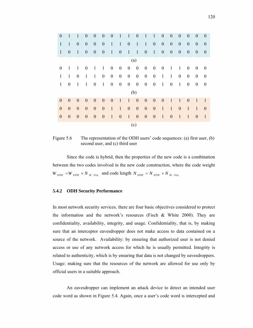
120
0 1 1 0 0 0 0 1 1 0 1 1 0 0 0 0 0 0
1 1 0 0 0 0 1 1 0 1 1 0 0 0 0 0 0 0
1 0 1 0 0 0 1 0 1 1 0 1 0 0 0 0 0 0
(a)
0 1 1 0 1 1 0 0 0 0 0 0 0 1 1 0 0 0
1 1 0 1 1 0 0 0 0 0 0 0 1 1 0 0 0 0
1 0 1 1 0 1 0 0 0 0 0 0 1 0 1 0 0 0
(b)
0 0 0 0 0 0 0 1 1 0 0 0 0 1 1 0 1 1
0 0 0 0 0 0 1 1 0 0 0 0 1 1 0 1 1 0
0 0 0 0 0 0 1 0 1 0 0 0 1 0 1 1 0 1
(c)
Figure 5.6 The representation of the ODH users’ code sequences: (a) first user, (b) second user, and (c) third user
Since the code is hybrid, then the properties of the new code is a combination
between the two codes involved in the new code construction, where the code weight
ODH EDW M SeqW W N −= × and code length ODH EDW M SeqN N N −= ×
5.4.2 ODH Security Performance
In most network security services, there are four basic objectives considered to protect
the information and the network’s resources (Fisch & White 2000). They are
confidentiality, availability, integrity, and usage. Confidentiality, that is, by making
sure that an interceptor eavesdropper does not make access to data contained on a
source of the network. Availability: by ensuring that authorized user is not denied
access or use of any network access for which he is usually permitted. Integrity is
related to authenticity, which is by ensuring that data is not changed by eavesdroppers.
Usage: making sure that the resources of the network are allowed for use only by
official users in a suitable approach.
An eavesdropper can implement an attack device to detect an intended user
code word as shown in Figure 5.4. Again, once a user’s code word is intercepted and
121
detected by the eavesdropper, the eavesdropper could have free access to the user’s
data until the user’s code is changed.
The probability that the eavesdropper can determine the official user’s entire
code word pulses with no errors will depend on the detection approach format and the
amount of time the eavesdropper observes the user’s transmission signal for each
detect. Based on classical detection analysis (Trees 2001), this probability can be
calculated from two quantities. These include the probability of missing a transmitted
pulse in a given time bin, MP , and the probability of falsely detecting a pulse in a bin
where none was transmitted, FP .
If the code interceptor receiver creates a code word decision based on
investigating and examining the transmitted signal for encoded spectral amplitude
coding optical CDMA data bit interval, the overall probability of correct code pulse
detection is expressed by equation (3.1) from Chapter III:
( )(1 ) (1 )W N W
correct M FP P P −= − − (5.18)
Then, applying the code properties of the ODH in equation (5.3) we get:
( )
[ ( 2 / , (2 )] [1 exp( )]N WODH ODH
ODHWcorrect o o oP Q E N N Nγ γ
−
= − − (5.19)
E refers here to the energy in an individual code pulse not the energy received during
an entire data bit. γ is the detection threshold and oN is the noise power spectral
density). Q is a function commonly called Marcum’s Q function (Trees 2001).
2 2
0( , ) exp( ) ( )2
zQ z I z dzβ
αα β α∞ +
≅ −∫ (5.20)
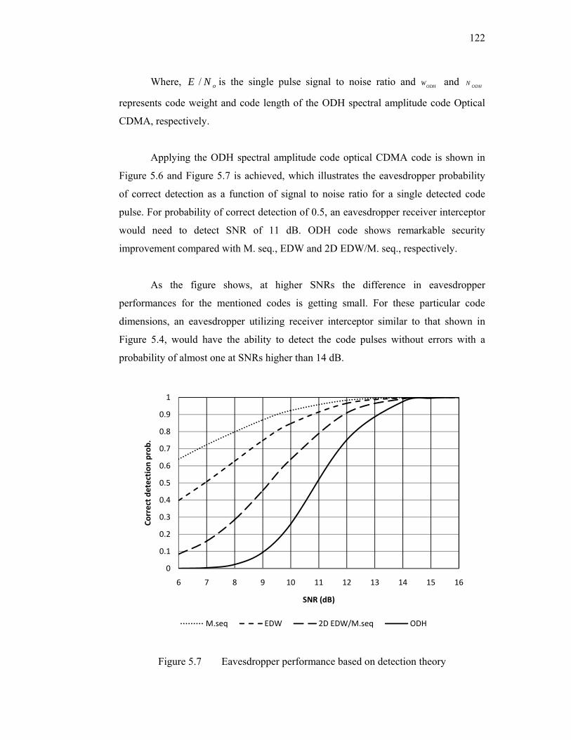
122
Where, / oE N is the single pulse signal to noise ratio and ODHW and ODHN
represents code weight and code length of the ODH spectral amplitude code Optical
CDMA, respectively.
Applying the ODH spectral amplitude code optical CDMA code is shown in
Figure 5.6 and Figure 5.7 is achieved, which illustrates the eavesdropper probability
of correct detection as a function of signal to noise ratio for a single detected code
pulse. For probability of correct detection of 0.5, an eavesdropper receiver interceptor
would need to detect SNR of 11 dB. ODH code shows remarkable security
improvement compared with M. seq., EDW and 2D EDW/M. seq., respectively.
As the figure shows, at higher SNRs the difference in eavesdropper
performances for the mentioned codes is getting small. For these particular code
dimensions, an eavesdropper utilizing receiver interceptor similar to that shown in
Figure 5.4, would have the ability to detect the code pulses without errors with a
probability of almost one at SNRs higher than 14 dB.
Figure 5.7 Eavesdropper performance based on detection theory
0
0.1
0.2
0.3
0.4
0.5
0.6
0.7
0.8
0.9
1
6 7 8 9 10 11 12 13 14 15 16
Correct d
etection
prob.
SNR (dB)
M.seq EDW 2D EDW/M.seq ODH

123
The extent of optical CDMA confidentiality is dependent of an eavesdropper
SNR and the eavesdropper SNR relies in turn on the parameters of a system design
and implementation. Thus, the confidentiality degree of an optical CDMA system may
be controlled by the system parameters.
In spectral amplitude coding optical CDMA schemes, most contribution of
noise comes from thermal noise, shot noise and PIIN (Smith et al. 1998; Wei et al.
2001).The eavesdropper photocurrent variance resulting from the use of band limited
photodetector as shown in Figure 5.4 can be expressed as:
2
2 2 42 ( 1) ( 1). ( 1)
sr sr b nODH ODH
ODH ODH ODH L
P P K KT BI eB W K B W KN V N W R
= ℜ + − + ℜ + − +Δ −
(5.21)
The first, second, and third terms represent, shot, thermal, and PIIN noises
respectively. Where e is an electron charge, B is the electrical equivalent noise band-
width of the receiver, ℜis the photodiode responsively, srP is the effective power of a
broad-band source at the receiver, K the number of users, vΔ the optical source
bandwidth, bK is the Boltzmann’s constant, rT the absolute temperature of receiver
noise, and LR the load resistance.
Figure 5.8 shows the effect of encoded spectral chip on the detected SNR
achieved by eavesdropper receiver with different average received optical powers.
Wide bandwidth and high received optical powers would increase the eavesdropper
possibility to detect encoded spectral pulses. At low received optical power,
increasing spectral chip bandwidth has small affect on eavesdropper performance
leading to security improvement. The eavesdropper SNR is less than 8 dB at average
optical power of -30 dBm which is corresponding to BER of 10-3.
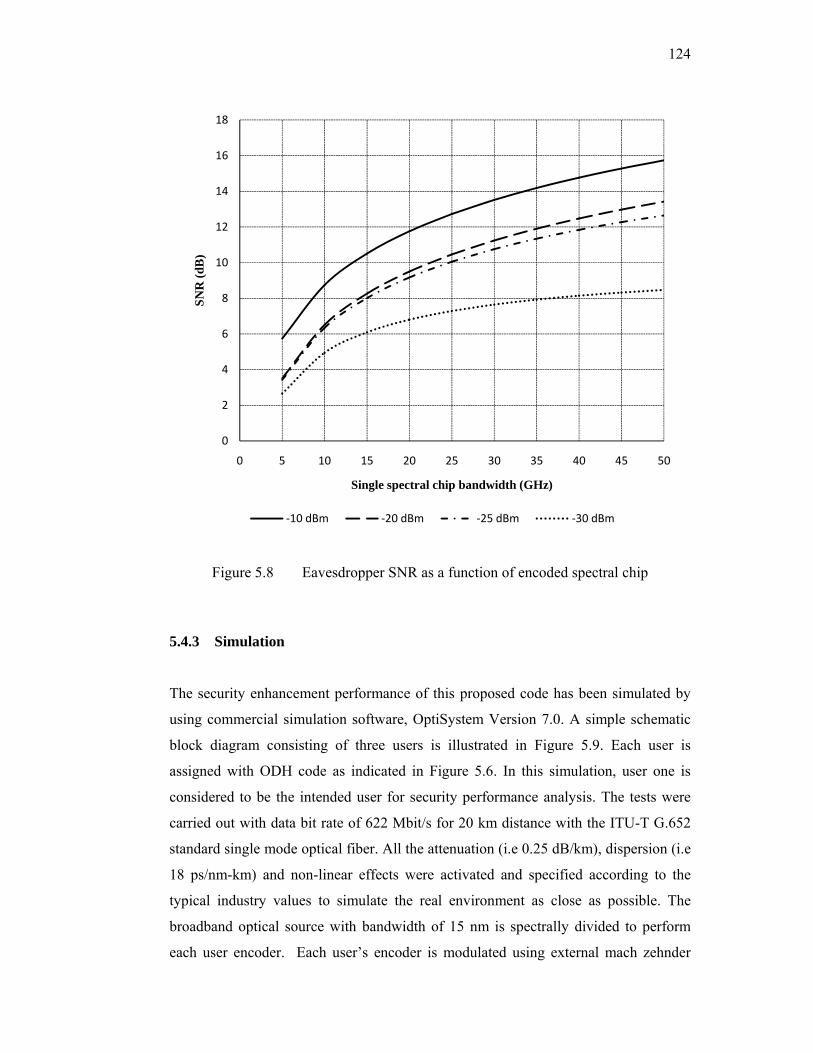
124
Figure 5.8 Eavesdropper SNR as a function of encoded spectral chip
5.4.3 Simulation
The security enhancement performance of this proposed code has been simulated by
using commercial simulation software, OptiSystem Version 7.0. A simple schematic
block diagram consisting of three users is illustrated in Figure 5.9. Each user is
assigned with ODH code as indicated in Figure 5.6. In this simulation, user one is
considered to be the intended user for security performance analysis. The tests were
carried out with data bit rate of 622 Mbit/s for 20 km distance with the ITU-T G.652
standard single mode optical fiber. All the attenuation (i.e 0.25 dB/km), dispersion (i.e
18 ps/nm-km) and non-linear effects were activated and specified according to the
typical industry values to simulate the real environment as close as possible. The
broadband optical source with bandwidth of 15 nm is spectrally divided to perform
each user encoder. Each user’s encoder is modulated using external mach zehnder
0
2
4
6
8
10
12
14
16
18
0 5 10 15 20 25 30 35 40 45 50
SNR
(dB
)
Single spectral chip bandwidth (GHz)
‐10 dBm ‐20 dBm ‐25 dBm ‐30 dBm

125
modulator before multiplexed in the single mode optical fiber. Both encoder and
decoder configurations are shown in Figure 5.10 which are based on the basic matrix
of both the EDW and m-sequence codes. Since the EDW code has code weight of
three, each code pulse will have 3 m-sequence spectral chips. Each chip has a spectral
width of 0.4 nm.
Figure 5.9 ODH system block diagram
Figure 5.11 shows the encoded spectrum of the transmitted signal intensity for
each single user and after multiplexer. These results are measured by optical spectrum
analyser (OSA) with resolution of 0.01 nm. These test measurements are taken to
ensure that each user is assigned with its corresponding proposed ODH code as
indicated in Figure 5.6. Figure 5.12 shows the encoded spectrum, measured by OSA,
of the transmitted signal for all users and each two users after multiplexer.
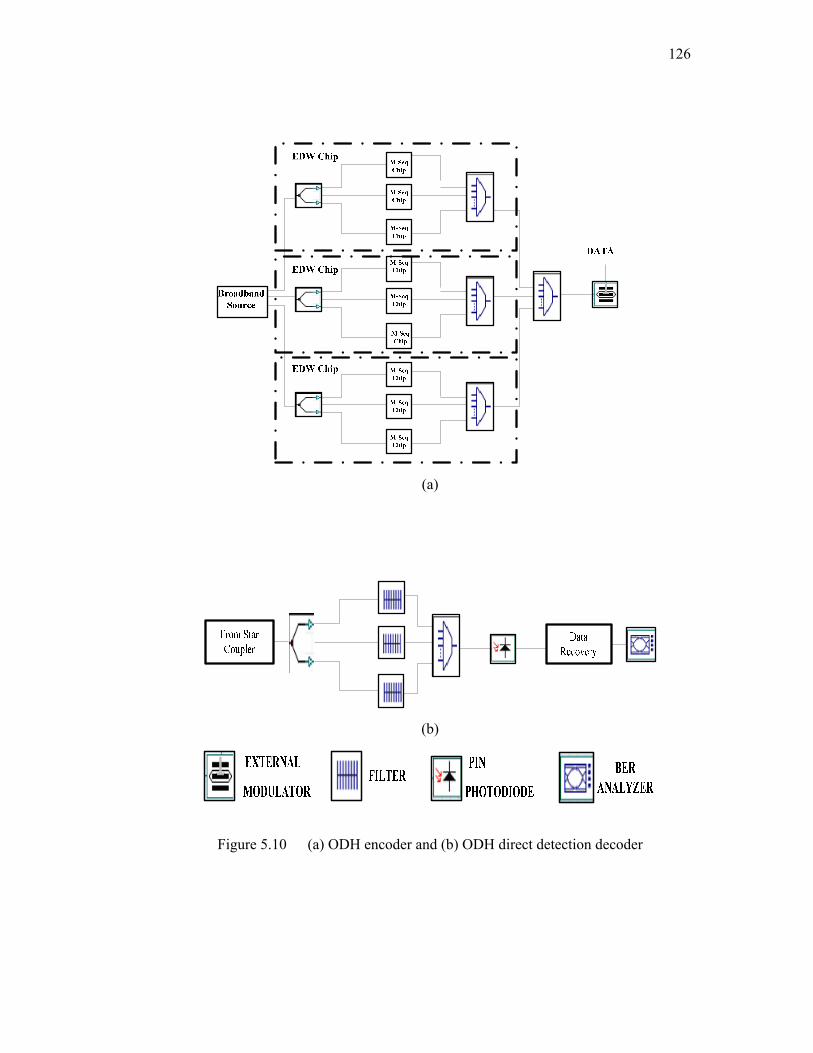
126
(a)
(b)
Figure 5.10 (a) ODH encoder and (b) ODH direct detection decoder
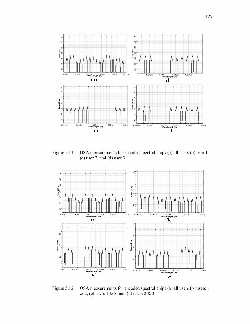
127
Figure 5.11 OSA measurements for encoded spectral chips (a) all users (b) user 1, (c) user 2, and (d) user 3
Figure 5.12 OSA measurements for encoded spectral chips (a) all users (b) users 1 & 2, (c) users 1 & 3, and (d) users 2 & 3

128
At the receiver side of the system, direct detection techniques have been
implemented for authorized user detection (Abdullah et al. 2008; Hasoon et al.
2007b). The spectral direct detection (SDD) technique has shown better performance
in comparison with the complementary one. In this particular simulation the
eavesdropper may tap encoded pulses corresponding to user one by using the same
receiver structure as shown in Figure 5.4.
The system performance has been described by observing and measuring
detected spectral chip SNRs and eye patterns. When only user one is active in the
network, the eavesdropper could obtain encoded spectral pulses with SNR of nearly
10 dB as shown in Figure 5.13. Therefore, the eavesdropper probability of correct
detection of nearly 0.25 is achieved as illustrated in Figure 5.7. This implies security
improvement in comparison with conventional SAC optical CDMA such as m-
sequence and EDW codes. In these conventional codes, eavesdropper could achieve a
probability of correct detection of more than 0.8 when detecting encoded pulses with
SNR of 10 dB.
Figure 5.13: Encoded spectral pulses after eavesdropping from user one in an isolated situation (only user one is active in the network)
0
2
4
6
8
10
12
1543
1544
1545
1546
1547
1548
1549
1550
1551
1552
1553
SNR
(dB
)
Wavelength (nm)

129
The corresponding eye diagrams for both eavesdropper and authorized user are
shown in Figure 5.14. Since the detected encoded pulses do not have equal signal
intensities, two extreme eye patterns are chosen as minimum and maximum values for
the eavesdropper receiver.
Figure 5.14 Eye patterns (a) minimum for eavesdropper, (b) maximum for eavesdropper and (c) authorized user
Figure 5.15 and Figure 5.16 show the encoded spectral chips that have been
detected by eavesdropper when there are two active users and three active users
respectively. From these two particular cases, it is clear that when the network has
more than one active user, additional difficulties are added for the eavesdropper
because of the multiple user interference (MUI) influence which is considered to be
the main problem in most optical CDMA technology. However, according to (Shake
2005b), it is shown that the per chip eavesdropper SNR is increased with the
increment of the system capacity, there by leading to tradeoffs between security and
system performance.

130
Figure 5.15 Encoded spectral pulses after eavesdropping from user one (when only two users are active in the network)
Figure 5.16 Encoded spectral pulses after eavesdropping from user one (when all users are active in the network)
Therefore, the results shown in Figure 5.15 and Figure 5.16 depict these
tradeoffs within this simulated network. Since all users are sharing specified spectral
chip bandwidths, this will give an advantage for the eavesdropper to detect some of
the encoded pulses with higher SNRs. The corresponding eye diagrams, when only
two users or three users are active, are shown in Figure 5.17 and Figure 5.18
respectively. Because the detected encoded pulses do not have identical signal
intensities, two extreme eye patterns are selected as minimum and maximum values
for the eavesdropper receiver.
0
2
4
6
8
10
12
14
1543
1544
1545
1546
1547
1548
1549
1550
1551
1552
1553
1554
1555
1556
SNR
(dB
)
Wavelength (nm)
0
2
4
6
8
10
12
14
16
1543
1544
1545
1546
1547
1548
1549
1550
1551
1552
1553
1554
1555
1556
1557
1558
SNR
(dB
)
Wavelength (nm)
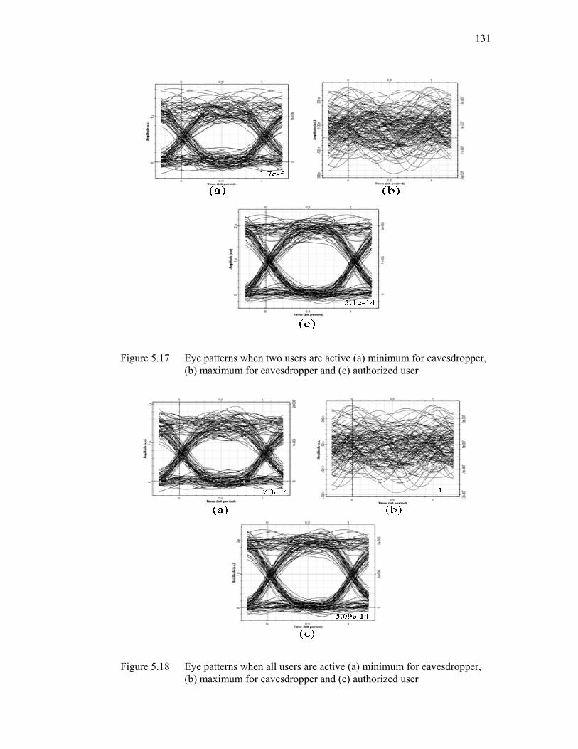
131
Figure 5.17 Eye patterns when two users are active (a) minimum for eavesdropper, (b) maximum for eavesdropper and (c) authorized user
Figure 5.18 Eye patterns when all users are active (a) minimum for eavesdropper, (b) maximum for eavesdropper and (c) authorized user
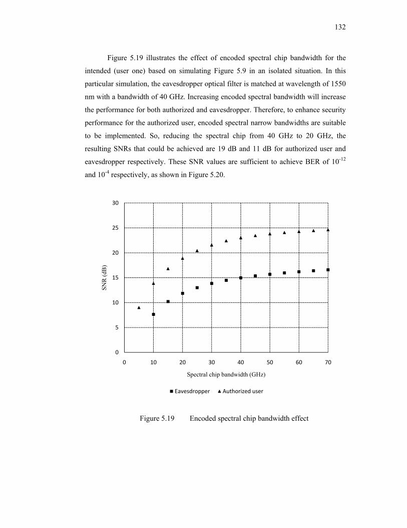
132
Figure 5.19 illustrates the effect of encoded spectral chip bandwidth for the
intended (user one) based on simulating Figure 5.9 in an isolated situation. In this
particular simulation, the eavesdropper optical filter is matched at wavelength of 1550
nm with a bandwidth of 40 GHz. Increasing encoded spectral bandwidth will increase
the performance for both authorized and eavesdropper. Therefore, to enhance security
performance for the authorized user, encoded spectral narrow bandwidths are suitable
to be implemented. So, reducing the spectral chip from 40 GHz to 20 GHz, the
resulting SNRs that could be achieved are 19 dB and 11 dB for authorized user and
eavesdropper respectively. These SNR values are sufficient to achieve BER of 10-12
and 10-4 respectively, as shown in Figure 5.20.
Figure 5.19 Encoded spectral chip bandwidth effect
0
5
10
15
20
25
30
0 10 20 30 40 50 60 70
SNR
(dB
)
Spectral chip bandwidth (GHz)
Eavesdropper Authorized user

133
Figure 5.20 Eye patterns when user one is active at spectral chip of 20 GHz for (a) eavesdropper and (b) authorized user
5.5 SUMMARY
The enhancement of the transmission security has been presented and demonstrated in
this chapter. The enhancement has been achieved by proposing hybrid SAC optical
CDMA schemes. One dimension hybrid (ODH) EDW/M seq. and two dimensions
(2D) EDW/M seq. code systems have been implemented to provide a degree of
transmission security for SAC optical CDMA. ODH code shows remarkable security
improvement compared with M. seq., EDW and 2D EDW/M. seq., respectively. The
results showed that increasing the code size will force eavesdropper to acquire
encoded code pulses with low SNRs due to the code complexity. Therefore, a low
probability of correct detection is achieved in the case of hybrid schemes. In addition,
increasing spectral chip bandwidth has small affect on eavesdropper performance,
particularly at low received optical power that could lead to security improvement.
The eavesdropper SNR is found to be less than 8 dB at average optical power of -30
dBm, which is corresponding to BER of 10-3. Furthermore, we have simulated these
hybrid SAC optical CDMA systems using Optisystem software version 7 to present
eavesdropper performance. Based on ODH, we have shown that when only user one is
active in the network, the eavesdropper could obtain encoded spectral pulses with
SNR of nearly 10 dB, which could achieve probability of correct detection of 0.25.
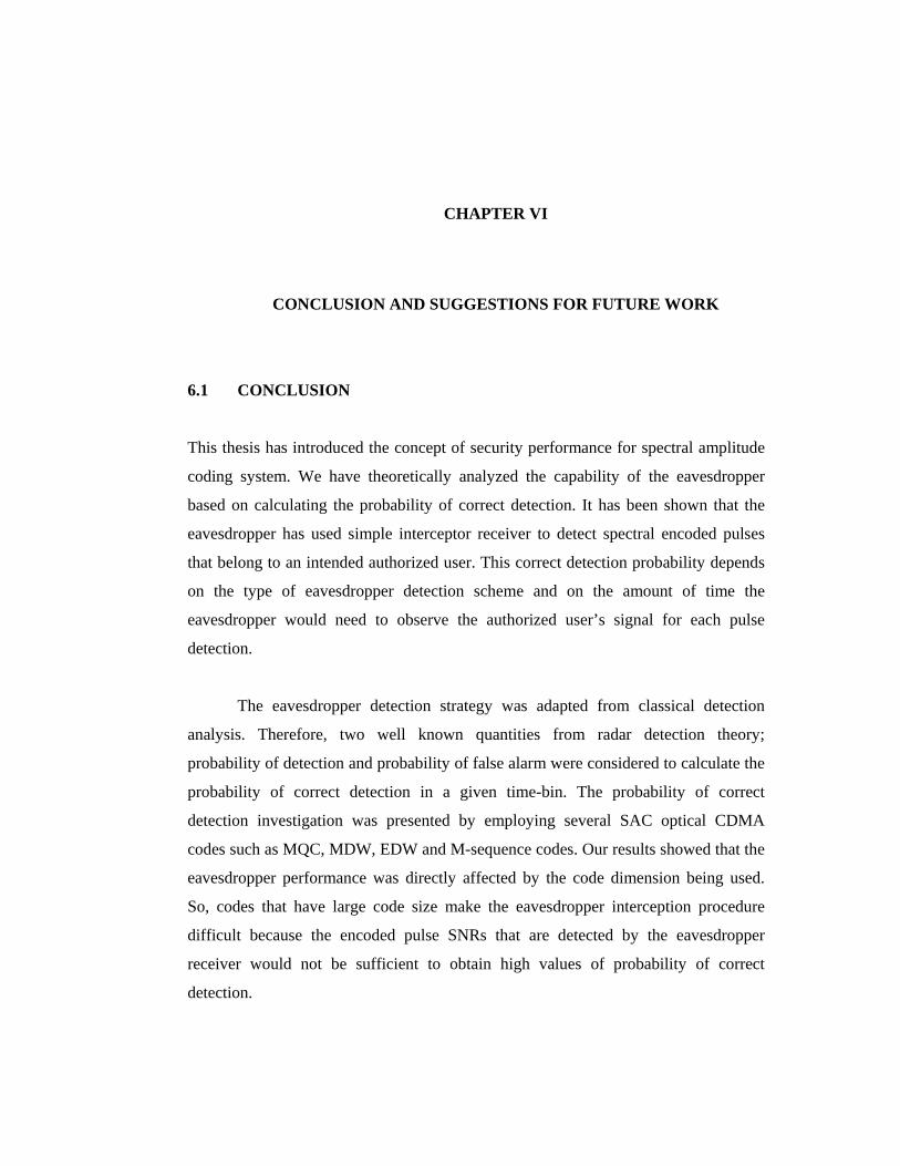
CHAPTER VI
CONCLUSION AND SUGGESTIONS FOR FUTURE WORK
6.1 CONCLUSION
This thesis has introduced the concept of security performance for spectral amplitude
coding system. We have theoretically analyzed the capability of the eavesdropper
based on calculating the probability of correct detection. It has been shown that the
eavesdropper has used simple interceptor receiver to detect spectral encoded pulses
that belong to an intended authorized user. This correct detection probability depends
on the type of eavesdropper detection scheme and on the amount of time the
eavesdropper would need to observe the authorized user’s signal for each pulse
detection.
The eavesdropper detection strategy was adapted from classical detection
analysis. Therefore, two well known quantities from radar detection theory;
probability of detection and probability of false alarm were considered to calculate the
probability of correct detection in a given time-bin. The probability of correct
detection investigation was presented by employing several SAC optical CDMA
codes such as MQC, MDW, EDW and M-sequence codes. Our results showed that the
eavesdropper performance was directly affected by the code dimension being used.
So, codes that have large code size make the eavesdropper interception procedure
difficult because the encoded pulse SNRs that are detected by the eavesdropper
receiver would not be sufficient to obtain high values of probability of correct
detection.

135
The performance analysis of the eavesdropper SNR is also investigated in this
thesis. Based on modified quadratic congruence MQC, a SAC optical CDMA code
system, the eavesdropper SNR equation is derived. The eavesdropper is assumed to
have the ability to implement a receiver interceptor that has direct detection scheme.
In addition, thermal noise, shot noise and phase induced intensity noise PIIN are
considered to be the main noise contributions in this analysis. As we have shown,
wide bandwidth of encoded spectral chip bandwidth (ESCB) improved the
performance for both authorized user and eavesdropper receiver. Therefore, reducing
encoding spectral bandwidth would force the eavesdropper to use other techniques
such as commercial error correction systems used to maintain an acceptable BER,
which will add another difficulty to the eavesdropper code interception process. This
does not mean that it is impossible for eavesdropper to have such equipments,
especially those intelligent adversaries. In addition, the same procedure has been
applied to the MDW code scheme. Here, we have determined the MDW code
properties that are required for eavesdropper direct detection scheme. Our results
showed that the MQC codes have slightly better security performance than the MDW
codes. Therefore, based on probability of correct detection, MQC (12, 4) has 0.3 dB
preference over MDW (9, 4).
Particularly, employing SAC optical CDMA with nearly same code space
size, our results demonstrated that using unipolar optical CDMA codes schemes based
on MQC and modified double weight MDW code system enhanced the security with a
low cost implementation in comparison to the bipolar ones based on modified
pseudorandom noise (PN) code. From the security viewpoint, one should minimize
the eavesdropper capability to detect code word pulses by controlling the authorized
performance to acceptable throughput.
The powerful computer software, Optisystem version 7, has been used to
implement SAC optical CDMA code systems. Mostly, the simulation layout project
properties such as global specification, attenuation, dispersion and nonlinear effects
were activated and specified according to the typical industry values to simulate the
real optical communication networks environment as close as possible. The simulation
results of eavesdropper agreed well with the theoretical analysis. For on-off keying

136
modulation system used in this simulation, optical CDMA scheme cannot ensure
physical layer security any more if there is only one active user in the network. When
all users were active the eavesdropper encountered multiple access interference due to
the reception of other users code addresses. However, he may still have a chance to
isolate that intended user.
We have proposed hybrid SAC optical CDMA systems to enhance security
performance. One dimension hybrid (ODH) EDW/M-sequence and two dimensions
(2D) EDW/M-sequence code systems have been implemented to provide a degree of
transmission security for SAC optical CDMA. The hybrid schemes were implemented
by combining the advantages of the code properties from unipolar code schemes such
as M-sequence and EDW. The security enhancements were investigated based on
calculating both the probability of correct detection and the detected eavesdropper
SNRs for the encoded spectral chip bandwidth. The hybrid schemes showed
remarkable security enhancement in comparison to the conventional SAC optical
CDMA codes. For probability of correct detection of 0.5, an eavesdropper receiver
interceptor would need to detect SNRs of 9.2 dB and 11 dB for (2D) EDW/M seq. and
ODH schemes respectively.
The ODH code was simulated using Optisystem software. Three users SAC
optical CDMA network were implemented where each user was assigned with an
ODH code. In this simulation, user one was considered to be the intended user for
security performance analysis. The simulation performance was presented by
observing and measuring detected spectral chip SNRs and eye patterns. When only the
intended user was active in the network, the eavesdropper achieved encoded spectral
pulses with SNR of nearly 10 dB; this value is capable to obtain a probability of
correct detection of nearly 0.25. This implies security improvement in comparison
with conventional SAC optical CDMA. When there was more than one active user
communicating simultaneously in the network, the eavesdropper encountered
additional difficulties to achieve good performance to solve the intended user code
address. This is because of the Multiple User Interference (MUI) influence which is
considered to be the main problem in most optical CDMA technology.
137
In this thesis, we have shown the tradeoffs between network system and
eavesdropper security performance. The theoretical and simulation analysis were
presented based on several SAC optical CDMA codes.
6.2 SUGGESTIONS FOR FUTURE WORK
It has been shown that optical CDMA provides transmission security at the physical
layer of an optical communication network. Therefore, the suitability of optical
CDMA for providing these types of security remains an uncovered issue for
investigation. The transmission security, based on confidentiality, is considered to be
one of the best recognized features of network transmission security that has been
published so far. In addition, there are many other types of security such as
availability, integrity and authentication that have not been published widely based on
optical CDMA networks. In other words, there are many issues related to security of
optical CDMA networks, which remain an open area for further research that can offer
security functions such as authentication, jamming resistance, and covertness.
Based on the investigation of the transmission security for optical CDMA, we
have suggested several recommendations for future research. These recommendations
should not be observed as being exhaustive. However, they can enhance practical and
realistic application of optical CDMA systems.
With regard to the covertness, we suggest that SAC optical CDMA will create
a covert communication channel in optical communication to transmit WDM signals.
The overall system turns out to be a hybrid SAC optical CDMA/WDM superimposed
scheme, which is performed by overlaying a covert signal onto a host signal in the
optical fiber transmission channel. Therefore, any of the SAC optical CDMA schemes
that has already been implemented in this analysis can be used, which will make the
eavesdropper unable to decode the authorized information without knowing the exact
code.
Since we have investigated transmission security based on SAC optical that
has on-off keying modulation, other modulations approaches can be used such as

138
phase shift keying (PSK) or 2-code keying and even M-code keying. In the 2-code
keying, each transmitted bit will require to have one code sequence for a “1” and a
different code sequence for a “0”. This modulation will create more difficulties for the
eavesdropper to correctly detect and decode the authorized user’s assigned code.
As mentioned before, more studies can be carried out to enhance transmission
security for optical CDMA in general, which remain an open area for further research.
Therefore, more security analysis in the physical layer can be done using two and
three dimensional codes that already have been implemented. Wavelength-hopping
time-spreading (WHTS) system is a two-dimensional (2-D) coding approach that
spreads the codes in both the wavelength and time domains at the same time and
achieving increased code design flexibility as well as code performance. We believe
that three dimensional codes will enhance physical layer security due to the large code
space size that can be provided. Their encoding can be carried out in phase,
wavelength and time domains or in polarization, wavelength and time domains, which
are obtained by adding another encoding dimension on the basis of 2-D code systems.

REFERENCES Abdullah, M. K., Hasoon, F. N., Aljunid, S. A. & Shaari, S. 2008. Performance of
OCDMA systems with new spectral direct detection (SDD) technique using enhanced double weight (EDW) code. Optics Communications 281 (18): 4658-4662.
Alexander, S. B. 1997. Optical Communication Receiver Design. Bellingham: The
Society of Photo-Optical Instrumentation Engineers. Alfiad, M. S., van den Borne, D., Hauske, F. N., Napoli, A., Koonen, A. M. J. & de
Waardt, H. 2009. Maximum-Likelihood Sequence Estimation for Optical Phase-Shift Keyed Modulation Formats. Journal of Lightwave Technology 27 (20): 4583-4594.
Aljunid, S. A., Ismail, M., Ramli, A. R., Ali, B. M. & Abdullah, M. K. 2004. A new
family of optical code sequences for spectral-amplitude-coding optical CDMA systems. IEEE Photonics Technology Letters 16 (10): 2383-2385.
Allen, J. H. 2001. The CERT Guide to System and Network Security Practices.
Boston: Addison-Wesley. Baby, V., Glesk, I., Runser, R. J., Fischer, R., Huang, Y.-K., Bres, C.-S., Kwong, W.
C., Curtis, T. H. & Prucnal, P. R. 2005 Experimental demonstration and scalability analysis of a 4-node 102 Gchip/s fast frequency-hopping time-spreading optical CDMA network. IEEE Photon. Technol. Lett. 17 (1): 253-255.
Banerjee, A., Park, Y., Clarke, F., Song, H., Yang, S., Kramer, G., Kim, K. &
Mukherjee, B. 2005. Wavelength-division-multiplexed passive optical network (WDM-PON) technologies for broadband access: a review [Invited]. J. Opt. Netw. 4 (11): 737-758.
Cao, Z. & Qian, Y. 1992. The Principle of Modern Telecommunication. Beijing:
Tsinghua university press. Cederlof, J. & Larsson, J. A. 2008. Security Aspects of the Authentication Used in
Quantum Cryptography. IEEE Transactions on Information Theory 54 (4): 1735-1741.
Chao-Chin, Y., Jen-Fa, H. & Shin-Pin, T. 2004. Optical CDMA network codecs
structured with M-sequence codes over waveguide-grating routers. IEEE Photonics Technology Letters 16 (2): 641-643.
Chung, F. R. K., Salehi, J. A. & Wei, V. K. 1989. Optical orthogonal codes: design,
analysis and applications. IEEE Transactions on Information Theory 35 (3): 595-604.

140
Chung, H. S., Chang, S. H., Kim, B. K. & Kim, K. 2008. Experimental demonstration of security-improved OCDMA scheme based on incoherent broadband light source and bipolar coding. Optical Fiber Technology 14 (2): 130-133.
DeLange, O. E. 1970. Wide-band optical communication systems: Part
II—Frequency-division multiplexing. Proceedings of the IEEE 58 (10): 1683-1690.
Deng, Y., Fok, M. P. & Prucnal, P. R. 2008. Demonstration of 2-D wavelength-
hopping time-spreading incoherent optical CDMA network by pulse carving of CW laser source. 42nd Annual Conference on Information Sciences and Systems CISS 2008: 341-343.
Dhillon, G. 2007. Principles of Information Systems Security: Text and Cases. New
York: John Wiley & Sons. Dillard, R. A. 1979. Detectability of Spread-Spectrum Signals. IEEE Transactions on
Aerospace and Electronic Systems AES-15 (4): 526-537. Dixon, R. C. 1976. Spread Spectrum System. New York: A Wiley-Interscience
Publication. Fathallah, H., Rusch, L. A. & LaRochelle, S. 1999. Passive optical fast frequency-hop
CDMA communications system. Journal of Lightwave Technology 17 (3): 397-405.
Ferguson, N. & Schneier, B. 2003. Practical Cryptography. Indianapolis: Wiley. Fisch, E. A. & White, G. B. 2000. Secure Computers and Networks: Analysis, Design,
and Implementation (Electronics Handbook). Boca Raton: CRC press. Gagliardi, R. M., Mendez, A. J., Dale, M. R. & Park, E. 1993. Fiber-optic digital
video multiplexing using optical CDMA. Journal of Lightwave Technology 11 (1): 20-26.
Glenn, A. 1983. Low probability of intercept. IEEE Communications Magazine 21
(4): 26-33. Griffin, R. A., Sampson, D. D. & Jackson, D. A. 1992. Optical phase coding for code-
division multiple access networks. IEEE Photonics Technology Letters 4 (12): 1401-1404.
Griffin, R. A., Sampson, D. D. & Jackson, D. A. 1995. Coherence coding for photonic
code-division multiple access networks. Journal of Lightwave Technology 13 (9): 1826-1837.
Hasoon, F. N., Abdullah, M. K., Aljunid, S. A. & Shaari, S. 2007a. Construction of a
new code for spectral amplitude coding in optical code-division multiple-access systems. Optical Engineering 46 (7): 075004.

141
Hasoon, F. N., Abdullah, M. K., Aljunid, S. A. & Shaari, S. 2007b. Performance of
OCDMA systems using a complementary subtraction technique. J. Opt. Netw. 6 (7): 854-859.
Hassan, A. A., Hershey, J. E. & Riza, N. A. 1995. Spatial optical CDMA. IEEE
Journal on Selected Areas in Communications, 13 (3): 609-613. Hernandez, V. J., Cong, W., Hu, J., Yang, C., Fontaine, N. K., Scott, R. P., Ding, Z.,
Kolner, B. H., Heritage, J. P. & Yoo, S. J. B. 2007. A 320-Gb/s Capacity (32-User × 10 Gb/s) SPECTS O-CDMA Network Testbed With Enhanced Spectral Efficiency Through Forward Error Correction. Journal of Lightwave Technology 25 (1): 79-86.
Holmes, A. S. & Syms, R. R. A. 1992. All-optical CDMA using `quasi-prime' codes.
Journal of Lightwave Technology 10 (2): 279-286. Hui, J. 1985. Pattern Code Modulation and Optical Decoding--A Novel Code-
Division Multiplexing Technique for Multifiber Networks. IEEE Journal on Selected Areas in Communications, 3 (6): 916-927.
Ipatov, V. 2005. Spread Spectrum and CDMA:Principles and applications. West
Sussex: John Wiley & Sons. Ishio, H., Minowa, J. & Nosu, K. 1984. Review and status of wavelength-division-
multiplexing technology and its application. Journal of Lightwave Technology 2 (4): 448-463.
Iversen, K. & Hampicke, D. 1995 Comparison and classification of all-optical CDMA
systems for future telecommunication networks. Proceedings of SPIE 2614: 110-121
Jiang, Z., Seo, D. S., Yang, S. D., Leaird, D. E., Roussev, R. V., Langrock, C., Fejer,
M. M. & Weiner, A. M. 2005. Four-user, 2.5-Gb/s, spectrally coded OCDMA system demonstration using low-power nonlinear processing. Journal of Lightwave Technology 23 (1): 143-158.
Jin-Hee, C. & Ing-Ray, C. 2005. On design tradeoffs between security and
performance in wireless group communicating systems. 1st IEEE ICNP Workshop on Secure Network Protocols (NPSec): 13-18.
Kamath, P., Touch, J. D. & Bannister, J. A. 2004. The need for media access control
in optical CDMA networks. Twenty-third Annual Joint Conference of the IEEE Computer and Communications Societies INFOCOM 2004: 2208-2219
Karafolas, N. & Uttamchandani, D. 1996. Optical Fiber Code Division Multiple
Access Networks: A Review. Optical Fiber Technology 2 (2): 149-168.

142
Kartalopoulos, S. V. 2007. Discriminating between Faults and Attacks in Secure Optical Networks. IEEE Military Communications Conference MILCOM: 1-5.
Kartalopoulos, S. V. 2009. Security in Advanced Optical Communication Networks.
IEEE International Conference on Communications ICC 2009: 1-5. Kavehrad, M. & Zaccarin, D. 1995. Optical code-division-multiplexed systems based
on spectral encoding of noncoherent sources. Journal of Lightwave Technology 13 (3): 534-545.
Kitayama, K. 1994. Novel spatial spread spectrum based fiber optic CDMA networks
for image transmission. IEEE Journal on Selected Areas in Communications 12 (4): 762-772.
Krasner, N. F. 1982. Maximum Likelihood Parameter Estimation for LPI Signals.
IEEE Military Communications Conference - Progress in Spread Spectrum Communications MILCOM 1982: 2.3-1-2.3-4.
Kwong, W. C., Perrier, P. A. & Prucnal, P. R. 1991. Performance comparison of
asynchronous and synchronous code-division multiple-access techniques for fiber-optic local area networks. IEEE Transactions on Communications, 39 (11): 1625-1634.
Kwong, W. C., Yang, G. C. & Liu, Y. C. 2005. A New Family of Wavelength-Time
Optical CDMA Codes Utilizing Programmable Arrayed Waveguide Gratings. IEEE Journal on Selected Areas in Communications, 23 (8): 1564-1571.
Lam, C. F. 2000. To spread or not to spread: the myths of optical CDMA. IEEE 13th
Annual Meeting Lasers and Electro-Optics Society LEOS 2000: 810-811. Lam, C. F., Tong, D. T. K., Wu, M. C. & Yablonovitvh, E. 1998. Experimental
demonstration of bipolar optical CDMA system using a balanced transmitter and complementary spectral encoding. IEEE Photonics Technology Letters 10 (10): 1504-1506.
Leaird, D. E., Jiang, Z. & Weiner, A. M. 2005. Experimental investigation of security
issues in OCDMA: a code-switching scheme. Electronics Letters 41 (14): 817-819.
Mahafza, B. R. & Elsherbeni, A. 2003 MATLAB Simulations for Radar Systems
Design. Boca Raton: Chapman & hall/CRC. Maric, S. V. 1993. New family of algebraically designed optical orthogonal codes for
use in CDMA fibre-optic networks. Electronics Letters 29 (6): 538-539. Maric, S. V., Hahm, M. D. & Titlebaum, E. L. 1995. Construction and performance
analysis of a new family of optical orthogonal codes for CDMA fiber-optic networks. IEEE Transactions on Communications 43 (234): 485-489.
143
Maric, S. V., Kostic, Z. I. & Titlebaum, E. L. 1993. A new family of optical code sequences for use in spread-spectrum fiber-optic local area networks. IEEE Transactions on Communications, 41 (8): 1217-1221.
Meghavoryan, D. M. & Baghdasaryan, H. V. 2001. Code-division multiple access:
novel multiplexing strategy in optical fiber networks. Proceedings of 3rd International Conference on Transparent Optical Networks: 299-303.
Mendez, A. J., Hernandez, V. J., Bennett, C. V., Gagliardi, R. M. & Lennon, W. J.
2005. Measurements of eavesdropping in a wavelength/time optical CDMA (O-CDMA) system, with data confidentiality implications. IEEE The 18th Annual Meeting of the Lasers and Electro-Optics Society LEOS 2005: 640-641.
Mohamed, M. A. A., Shalaby, H. M. H. & El-Badawy, E. S. A. M. 2006. Performance
analysis of an optical CDMA MAC protocol with variable-size sliding window. Journal of Lightwave Technology 24 (10): 3590-3597.
Narimanov, E., Kwong, W. C., Guu-Chang, Y. & Prucnal, P. R. 2005. Shifted carrier-
hopping prime codes for multicode keying in wavelength-time O-CDMA. IEEE Transactions on Communications 53 (12): 2150-2156.
Nguyen, L., Aazhang, B. & Young, J. F. 1995. All-optical CDMA with bipolar codes.
Electronics Letters 31 (6): 469-470. Optiwave. 2007. http://www.optiwave.com/index.html. Oyster Optics, Inc. 2003. Securing Fiber Optic Communications against Optical
Tapping Methods. White paper on optical taps and various solutions. URL: http://www.oysteroptics.com/index_resources.html
Oyster Optics, Inc. 2005. Fiber Optics and its Security Vulnerabilities. Research on Topics In Information Security from SANS Institute URL: http://www.oysteroptics.com/index_resources.html. Papannareddy, R. & Weiner, A. M. 1999. Performance comparison of coherent
ultrashort light pulse and incoherent broad-band CDMA systems. IEEE Photonics Technology Letters 11 (12): 1683-1685.
Park, E., Mendez, A. J. & Garmire, E. M. 1992. Temporal/spatial optical CDMA
networks-design, demonstration, and comparison with temporal networks. IEEE Photonics Technology Letters 4 (10): 1160-1162.
Peterson, R. L., Ziemer, R. E. & Borth, D. F. 1995. Introduction to Spread Spectrum
Communications. Englewood Cliffs: Prentice Hall. Pfeiffer, T., Deppisch, B., Witte, M. & Heidemann, R. 1999. Operational stability of a
spectrally encoded optical CDMA system using inexpensive transmitters without spectral control. IEEE Photonics Technology Letters 11 (7): 916-918.

144
Prasad, R. & Ojanpera, T. 1998. A survey on CDMA: evolution towards wideband CDMA. Proceeding IEEE 5th International Symposium on Spread Spectrum Techniques and Applications: 323-331.
Prucnal, P. R. 2006. Optical code division multiple access: fundamentals and
application. Boca Raton: CRC Press, Taylor &Francis Group. Prucnal, P., Santoro, M. & Sehgal, S. 1986. Ultrafast All-Optical Synchronous
Multiple Access Fiber Networks. IEEE Journal on Selected Areas in Communications 4 (9): 1484-1493.
Prucnal, P., Santoro, M. & Ting, F. 1986. Spread spectrum fiber-optic local area
network using optical processing. Journal of Lightwave Technology 4 (5): 547-554.
Qin, L., Yin, H., Liang, W., Wang, Z. & Xu, A. 2008. Security performance analysis
of an M-code keying OCDMA system. Photonic Network Communications 15 (1): 19-24.
Ramaswami, R. & Sivarajan, K. N. 1998. Optical Networks: A Practical Prespective.
San Francisco: Morgan Kaufimann Publishers. Salehi, J. A. & Brackett, C. A. 1989. Code division multiple-access techniques in
optical fiber networks. II. Systems performance analysis. IEEE Transactions on Communications 37 (8): 834-842.
Salehi, J. A. 1989. Code division multiple-access techniques in optical fiber networks.
I. Fundamental principles. IEEE Transactions on Communications, 37 (8): 824-833.
Salehi, J. A., Weiner, A. M. & Heritage, J. P. 1990. Coherent ultrashort light pulse
code-division multiple access communication systems. Journal of Lightwave Technology, 8 (3): 478-491.
Salehi, J. A., Weiner, A. M. & Heritage, J. P. 1989. Temporal and statistical analysis
of ultrashort light pulse code-division multiple access communications network. IEEE International Conference on Communications ICC 1989: 728-733.
Sampson, D. D., Griffin, R. A. & Jackson, D. A. 1994. Photonic CDMA by coherent
matched filtering using time-addressed coding in optical ladder networks. Journal of Lightwave Technology 12 (11): 2001-2010.
Sampson, D. D., Pendock, G. J. & Griffin, R. A. 1997. Photonic code-division
multiple-access communications. Fiber and Integrated Optics 16 (2): 129 - 157.

145
Sangin, K., Kyungsik, Y. & Park, N. 2000. A new family of space/wavelength/time spread three-dimensional optical code for OCDMA networks. Journal of Lightwave Technology 18 (4): 502-511.
Sari, H., Vanhaverbeke, F. & Moeneclaey, M. 2000. Extending the capacity of
multiple access channels. IEEE Communications Magazine 38 (1): 74-82. Schulze, H. & Lueders, C. 2005. Theory and Applications of OFDM and CDMA:
Wideband Wireless Communications. West Sussex: John Wiley & Sons Ltd. Shahab, E., Tom, B., Stefano, G., Janet, J., Ronald, M., Paul, T., Jeffrey, Y., Peter, D.,
Craig, P. & Terry, T. 2004. Optical-CDMA incorporating phase coding of coherent frequency bins: concept, simulation, experiment. IEEE Optical Fiber Communication Conference OFC2004:FG5.
Shake, T. H. 2005. Security performance of optical CDMA Against eavesdropping.
Journal of Lightwave Technology 23 (2): 655-670. Shake, T. H. 2005a. Confidentiality performance of spectral-phase-encoded optical
CDMA. Journal of Lightwave Technology 23 (4): 1652-1663. Shalaby, H. M. H. 2003. Optical CDMA Random Access Protocols With and Without
Pretransmission Coordination. Journalof Lightwave Technology 21 (11): 2455. Shaneman, K. & Gray, S. 2004. Optical network security: technical analysis of fiber
tapping mechanisms and methods for detection & prevention, at. IEEE Military Communications Conference MILCOM 2004: 711-716.
Simon, M. K., Omura, J. K., Scholtz, R. A. & Levitt, B. K. 2002. Spread Spectrum
Communications Handbook. Electronic Edition ed. New York: McGraw-Hill. Smith, E. D. J., Blaikie, R. J. & Taylor, D. P. 1998. Performance enhancement of
spectral-amplitude-coding optical CDMA using pulse-position modulation. IEEE Transactions on Communications 46 (9): 1176-1185.
Sokoloff, J. P., Prucnal, P. R., Glesk, I. & Kane, M. 1993. A terahertz optical
asymmetric demultiplexer. IEEE Photon. Technol. Lett. 5 (7): 787-790. Sotobayashi, H., Chujo, W. & Kitayama, K. I. 2001. 1.6 bit/s/Hz, 6.4 Tbit/s
OCDM/WDM (4 OCDM × 40 WDM × 40 Gbit/s) transmission experiment. 27th European Conference on Optical Communication ECOC 200: 6-7.
Stallings, W. 1995. Network and Internetwork Security: Principles and Practice. New
Jersey: Prentice Hall. Stavroulakis, P. 2006 Chaos Applications in Telecommunications. Boca Raton: Taylor
& Francis Group, LLC.

146
Stinson, D. R. 2002. Cryptography: Theory and Practice. Second Edition ed. Boca Raton: Chapman & hall/CRC, CRC Press LLC.
Sun, S., Yin, H., Wang, Z. & Xu, A. 2007. Performance analysis of a new random
access protocol for OCDMA networks. Photonic Network Communications 14 (1): 89-95.
Tancevski, L. & Andonovic, I. 1994. Wavelength hopping/time spreading code
division multiple access systems. Electronics Letters 30 (17): 1388-1390. Tancevski, L., Andonovic, I. & Budin, J. 1995. Secure optical network architectures
utilizing wavelength hopping/time spreading codes. IEEE Photonics Technology Letters 7 (5): 573-575.
Tancevski, L., Bazgaloski, L., Andonovic, I. & Budin, J. 1994. Incoherent
asynchronous optical CDMA using gold codes. Electronics Letters 30 (9): 721-723.
Tanenbaum, A. 1989. Computer Networks. 2ed ed. New Jersey: Prentice Hall. Tipton, H. F. & Krause, M. 2007. Information Security Management Handbook. Fifth
Edition ed. Vol. 2. Boca Raton: Auerbach Publications, Taylor & Francis Group.
Torres, P., Valente, L. C. G. & Carvalho, M. C. R. 2002. Security system for optical
communication signals with fiber Bragg gratings. IEEE Transactions on Microwave Theory and Techniques 50 (1): 13-16.
Trees, H. L. V. 2001. Detection, Estimation, and Modulation Theory, Part I. New
York: John Wiley & Sons. Viterbi, A. J. 1995. CDMA: Principles of Spread Spectrum Communication. 1st ed.
ed: Redwood: Prentice Hall PTR. Walle, H. & Killat, U. 1995. Combinatorial BER analysis of synchronous optical
CDMA with prime sequences. IEEE Transactions on Communications 43 (12): 2894-2895.
Wei, Z., Shalaby, H. M. H. & Ghafouri-Shiraz, H. 2001. Modified Quadratic
Congruence Codes for Fiber Bragg-Grating-Based Spectral-Amplitude-Coding Optical CDMA Systems. Journal of Lightwave Technology 19 (9): 1274.
Weiner, A. M., Heritage, J. P. & Salehi, J. A. 1988. Encoding and decoding of
femtosecond pulses. Opt. Lett. 13 (4): 300-302. Wolter, K. & Reinecke, P. 2010. Performance and Security Tradeoff in Formal
Methods for Quantitative Aspects of Programming Languages. Berlin: Springer Berlin / Heidelberg.
147
Xu, C., Xiang, L. & Xing, W. 2004. Differential phase-shift keying for high spectral efficiency optical transmissions. IEEE Journal of Selected Topics in Quantum Electronics 10 (2): 281-293.
Yang, C. C., Huang, J. F. & Chiu, I. M. 2007. Performance Analyses on Hybrid
MQC/M-Sequence Coding Over Frequency/Spatial Optical CDMA System. IEEE Transactions on Communications 55 (1): 40-43.
Yang, G. C. & Jaw, J. Y. 1994. Performance analysis and sequence designs of
synchronous code-division multiple-access systems with multimedia services. IEE Proceedings Communications 141 (6): 371.
Yang, G. C. 1995. Some new families of optical orthogonal codes for code-division
multiple-access fibre-optic networks. Communications, IEE Proceedings- 142 (6): 363-368.
Yang, G. C., Kwong, W. C. & (2):1. 1996. Two-Dimensional Spatial Signature
Patterns. IEEE Trans. Commun. 44 (2): 84–191. Yao-Tang, C., Chuan-Ching, S. & Jen-Fa, H. 2007. Robust Design for Reconfigurable
Coder/Decoders to Protect Against Eavesdropping in Spectral Amplitude Coding Optical CDMA Networks. Journal of Lightwave Technology 25 (8): 1931-1948.
Yegnanarayanan, S., Bhushan, A. S. & Jalali, B. 2000. Fast wavelength-hopping time-
spreading encoding/decoding for optical CDMA. IEEE Photonics Technology Letters 12 (5): 573-575.
Yim, R. M. H., Chen, L. R. & Bajcsy, J. 2002. Design and performance of 2-D codes
for wavelength-time optical CDMA. IEEE Photon. Technol. Lett. 14 (5): 714–716.
Yin, H. & Richardson, D. J. 2007. Optical Code Division Multiple Access
Communication Networks Theory and Applications. Beijing: Tsinghua University Press.
Zaccarin, D. & Kavehrad, M. 1993. An optical CDMA system based on spectral
encoding of LED. IEEE Photonics Technology Letters 5 (4): 479-482. Zaccarin, D. & Kavehrad, M. 1994a. New architecture for incoherent optical CDMA
to achieve bipolar capacity. Electronics Letters 30 (3): 258-259. Zaccarin, D. & Kavehrad, M. 1994b. Performance evaluation of optical CDMA
systems using non-coherent detection and bipolar codes. Journal of Lightwave Technology 12 (1): 96-105.
Zhou, X., Shalaby, H. M. H., Lu, C. & Cheng, T. 2000. Code for spectral amplitude
coding optical CDMA systems. Electron Letter 36 (8): 728–729.
148
Ziemer, R. E. 2007. Fundamentals of Spread Spectrum Modulation. United States of America: Morgan & Claypool publishers.
Zou, W. & Ghafouri-Shiraz, H. 2002a. Codes for spectral-amplitude-coding optical
CDMA systems. Journal of Lightwave Technology 20 (8): 1284-1291. Zou, W. & Ghafouri-Shiraz, H. 2002b. Proposal of a novel code for spectral
amplitude-coding optical CDMA systems. IEEE Photonics Technology Letters 14 (3): 414-416.
Zou, W. & Ghafouri-Shiraz, H. 2002c. Unipolar codes with ideal in-phase cross-
correlation for spectral amplitude-coding optical CDMA systems. IEEE Transactions on Communications 50 (8): 1209-1212.
Zou, W., Ghafouri-Shiraz, H. & Shalaby, H. M. H. 2001. New code families for fiber- Bragg-grating-based spectral-amplitude-coding optical CDMA systems. IEEE Photonics Technology Letters 13 (8): 890-892. Zou, W., Shalaby, H. M. H. & Ghafouri-Shiraz, H. 2001. Modified quadratic
congruence codes for fiber Bragg-grating-based spectral-amplitude-coding optical CDMA systems. Journal of Lightwave Technology 19 (9): 1274-1281.
149
APPENDIX A
LIST OF PUBLICATIONS
Journals Bakarman, H. A., Shaari, S. & Ismail, M. 2009. Security Performance of Spectral
Amplitude Code OCDMA: Spectrally Encoded Pulse Bandwidth Effects. J. Opt. Commun. 30 (4): 242-247
Bakarman, H.A.; Zahid, A.Z.G.; Hasoon, F.N.; Shaari, S.; Ismail, M.; Eavesdropper SNR Performance based on Spectral Amplitude Code Optical CDMA. IET Communications (under review)
Bakarman, H.A.; Zahid, A.Z.G.; Hasoon, F.N.; Shaari, S.; Ismail, M.; Simulation of quadratic congruence code (MQC): Eavesdropper SNR Performance. Journal of Research IETE (under review) Bakarman, H.A.; Zahid, A.Z.G.; Hasoon, F.N.; Shaari, S.; Ismail, M.; One Dimension Hybrid SAC Optical CDMA Code Design and Security performance. Optical Fiber Technology - Elsevier (under review) Bakarman, H.A.; Zahid, A.Z.G.; Hasoon, F.N.; Shaari, S.; Ismail, M.; Simulation of Eavesdropper performance based on One Dimension Hybrid SAC Optical CDMA. Photonic Network Communications (Submitted) Conference Proceedings
Bakarman, H. A., Shaari, S. & Ismail, M. 2008. Security performance of spectral
amplitude coding OCDMA systems. IEEE International Conference on Electronic Design, 2008. ICED 2008: 1-4.
Bakarman, H. A., Hasoon, F. N., Shaari, S. & Ismail, M. 2009. Tapping and detecting
optical signals from optical CDMA networks. IEEE International Conference on Signal and Image Processing Applications (ICSIPA), 2009: 195-198.
Bakarman, H. A., Zahid, A. Z., Hasoon, F. N., Shaari, S. & Ismail, M. 2009.
Simulation of security performance for unipolar and bipolar Optical CDMA Network Systems. IEEE 9th Malaysia International Conference on Communications (MICC), 2009: 367-370.
Bakarman, H. A., Hasoon, F. N., Shaari, S. & Ismail, M. 2010. Security enhancement
for spectral amplitude coding OCDMA based on hybrid EDW/M seq. code systems. IEEE International Conference on Computer and Communication Engineering (ICCCE), 2010: 1-5.

150
Bakarman, H. A., Shaari, S. & Ismail, M. 2010. Security and performance tradeoffs in optical CDMA network systems. IEEE International Conference on Photonics (ICP), 2010: 1-4.
Bakarman, H. A., Shaari, S. & Ismail, M. 2010. Simulation of 1.25 Gb/s downstream
transmission performance of GPON-FTTx. IEEE International Conference on Photonics (ICP), 2010: 1-5.
Ashour, I. A. M., Shaari, S., Shalaby, H. M. H., Menon, P. S. & Bakarman, H. A.
2010. Hybrid SAC/Optical CDMA-WDM overlay system for enhancing network security. IEEE International Conference on Photonics (ICP), 2010: 1-4.
Book Chapter Hesham Bakarman, Sahbudin Shaari, P. Susthitha Menon Security Limitations of
Spectral Amplitude Coding based on Modified Quadratic Congruence Code Systems in Digital Communication (ISBN 979-953-307-545-6) will publish on March 2012