Security guide for Industrial Protocols Smart Grid · Security guide for Industrial Protocols Page...
24
CERT DE SEGURIDAD E INDUSTRIA MINISTERIO DEL INTERIOR GOBIERNO DE ESPAÑA MINISTERIO DE ENERGÍA, TURISMO Y AGENDA DIGITAL GOBIERNO DE ESPAÑA Security guide for Industrial Protocols Smart Grid
Transcript of Security guide for Industrial Protocols Smart Grid · Security guide for Industrial Protocols Page...
CERT DE SEGURIDADE INDUSTRIA
MINISTERIODEL INTERIOR
GOBIERNODE ESPAÑA
MINISTERIODE ENERGÍA, TURISMOY AGENDA DIGITAL
GOBIERNODE ESPAÑA
Security guide for Industrial ProtocolsSmart Grid

Security guide for Industrial Protocols Page 2 of 24
Smart Grid
February 2017
CERTSI_GUIA_SCI_002_ProtocolosSmartGrid_2017_v1
This publication belongs to INCIBE (Spanish National Cybersecurity Institute) and is licensed under a Creative Commons Attribution-Noncommercial 3.0 Spain License. For this reason, it is permitted to copy, distribute and communicate this work publicly under the following conditions:
• Acknowledgement. The content of this report may be reproduced in part or in full by third parties, with the appropriate acknowledgement and making express reference to INCIBE or CERTSI and its website: http://www.incibe.es. Under no circumstances shall said acknowledgement imply that INCIBE supports said third party or supports the use they make of this work.
• Non-commercial Use. The original material and the derived works may be distributed, copied and exhibited provided their use does not have a commercial purpose.
By reusing or distributing the work, the terms of the license of this work must be made clear. Some of these conditions may not apply if permission is obtained from CERTSI as owner of the authorship rights. Full text of the license: http://creativecommons.org/licenses/by-nc-sa/3.0/es/
Security guide for Industrial Protocols Page 3 of 24
Smart Grid
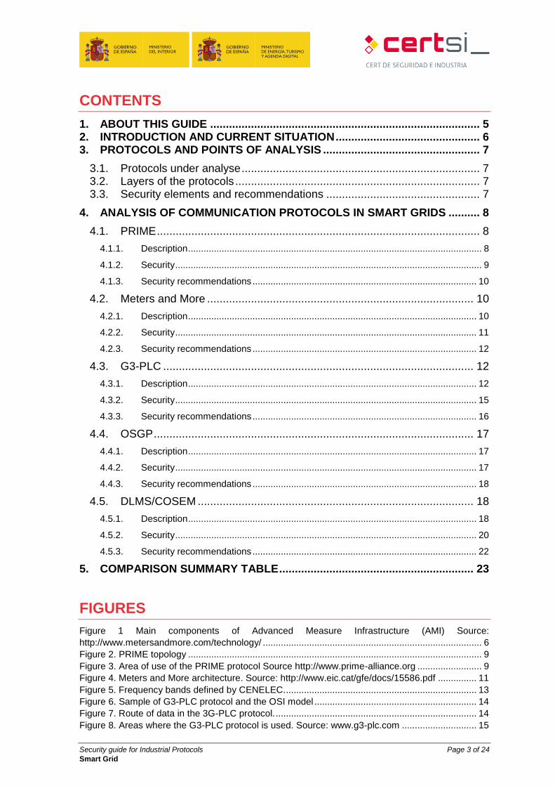
CONTENTS
1. ABOUT THIS GUIDE ...................................................................................... 5
2. INTRODUCTION AND CURRENT SITUATION .............................................. 6 3. PROTOCOLS AND POINTS OF ANALYSIS .................................................. 7
3.1. Protocols under analyse ............................................................................ 7 3.2. Layers of the protocols .............................................................................. 7 3.3. Security elements and recommendations ................................................. 7
4. ANALYSIS OF COMMUNICATION PROTOCOLS IN SMART GRIDS .......... 8
4.1. PRIME ....................................................................................................... 8
4.1.1. Description .................................................................................................................. 8
4.1.2. Security ....................................................................................................................... 9
4.1.3. Security recommendations ....................................................................................... 10
4.2. Meters and More ..................................................................................... 10
4.2.1. Description ................................................................................................................ 10
4.2.2. Security ..................................................................................................................... 11
4.2.3. Security recommendations ....................................................................................... 12
4.3. G3-PLC ................................................................................................... 12
4.3.1. Description ................................................................................................................ 12
4.3.2. Security ..................................................................................................................... 15
4.3.3. Security recommendations ....................................................................................... 16
4.4. OSGP ...................................................................................................... 17
4.4.1. Description ................................................................................................................ 17
4.4.2. Security ..................................................................................................................... 17
4.4.3. Security recommendations ....................................................................................... 18
4.5. DLMS/COSEM ........................................................................................ 18
4.5.1. Description ................................................................................................................ 18
4.5.2. Security ..................................................................................................................... 20
4.5.3. Security recommendations ....................................................................................... 22
5. COMPARISON SUMMARY TABLE .............................................................. 23
FIGURES
Figure 1 Main components of Advanced Measure Infrastructure (AMI) Source:
http://www.metersandmore.com/technology/ ..................................................................................... 6 Figure 2. PRIME topology .................................................................................................................. 9 Figure 3. Area of use of the PRIME protocol Source http://www.prime-alliance.org ......................... 9 Figure 4. Meters and More architecture. Source: http://www.eic.cat/gfe/docs/15586.pdf ............... 11 Figure 5. Frequency bands defined by CENELEC........................................................................... 13 Figure 6. Sample of G3-PLC protocol and the OSI model ............................................................... 14 Figure 7. Route of data in the 3G-PLC protocol. .............................................................................. 14 Figure 8. Areas where the G3-PLC protocol is used. Source: www.g3-plc.com ............................. 15
Security guide for Industrial Protocols Page 4 of 24
Smart Grid
Figure 9. Confidentiality and security thanks the encrypted communication in G3-PLC. Source:
www.erdf.fr ....................................................................................................................................... 16 Figure 10. Intensities at which devices using the OSGP protocol operate Source: www.esna.org . 17 Figure 11. Model of DLMS/COSEM layers ...................................................................................... 19 Figure 12. DLMS/COSEM architecture. Source: www.dlms.com .................................................... 20 Figure 13. DLMS/COSEM Authentication ........................................................................................ 21 Figure 14. Security in DLMS/COSEM packets. Source: www.dlms.com ......................................... 21
TABLES
Table 1. Table of summary of protocols in smart networks. ............................................................ 23
Security guide for Industrial Protocols Page 5 of 24
Smart Grid
1. ABOUT THIS GUIDE
Following the line of the study “Protocols and network security in ICS infrastructure”1,
published by INCIBE, where a vision of the most representative protocols in control
systems is offered, this document intends to take a deeper look at the protocols used in
smart grids.
This study, of a technical nature, is centred on smart grid communications, and is
intended to offer a vision of the most used protocols in Spain and Europe showing their
functionalities, the security measures they offer and the problems they face. Similarly, a
series of recommendations are provided in each of them, for the purpose of improving the
security of the facilities that have implemented them.
1 https://www.incibe.es/extfrontinteco/img/File/intecocert/ManualesGuias/incibe_protocolos_seguridad_red_sci.pdf
Security guide for Industrial Protocols Page 6 of 24
Smart Grid
2. INTRODUCTION AND CURRENT SITUATION
For some years, the electricity grid has undergone a great transformation promoted,
above all, at European level through the "20-20-20 Objectives”2. The basis of the
modification of the electrical grid arises in the communication COM (2006) 786 "On a
European Programme for Critical Infrastructure Protection"3 of the European Commission,
where the principal aspects of the European Programme for Critical Infrastructures
Protection (EPCIP) were defined; and most importantly with the publication by the
European Commission of communication COM (2011) 202, “Smart Grids: from Innovation
to Deployment”4.
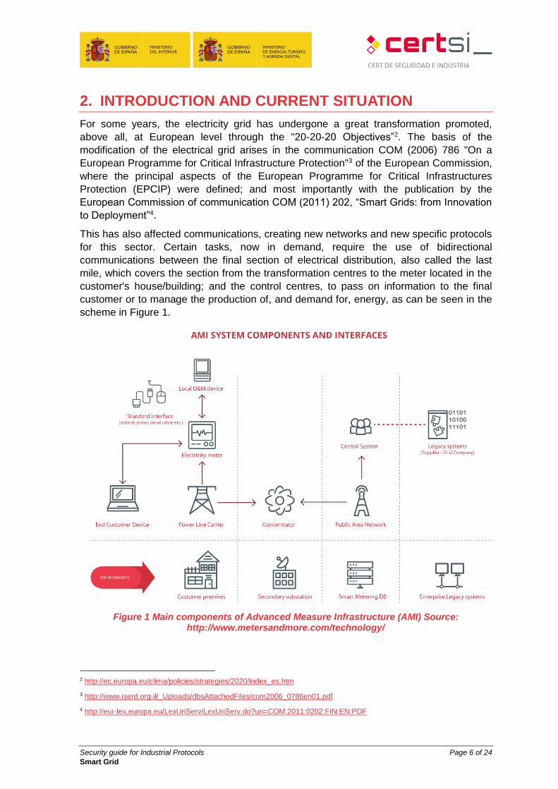
This has also affected communications, creating new networks and new specific protocols
for this sector. Certain tasks, now in demand, require the use of bidirectional
communications between the final section of electrical distribution, also called the last
mile, which covers the section from the transformation centres to the meter located in the
customer's house/building; and the control centres, to pass on information to the final
customer or to manage the production of, and demand for, energy, as can be seen in the
scheme in Figure 1.
Figure 1 Main components of Advanced Measure Infrastructure (AMI) Source: http://www.metersandmore.com/technology/
2 http://ec.europa.eu/clima/policies/strategies/2020/index_es.htm
3 http://www.iserd.org.il/_Uploads/dbsAttachedFiles/com2006_0786en01.pdf
4 http://eur-lex.europa.eu/LexUriServ/LexUriServ.do?uri=COM:2011:0202:FIN:EN:PDF
Security guide for Industrial Protocols Page 7 of 24
Smart Grid
3. PROTOCOLS AND POINTS OF ANALYSIS
3.1. Protocols under analyse
Thanks to the unification and standardisation established between energy distributors,
manufacturers and developers, the existence of protocols related to smart grids is not as
widespread as in other areas of industry. From among protocols arising from this
unification and standardisation, those used most commonly in Spain, along with those
most widely used across Europe, are analysed here.
The protocols selected are the following:
PRIME
Meters and More
DLMS/COSEM
G3-PLC
OSGP
3.2. Layers of the protocols
The industrial network protocols are, for the most part, new generation, implying a
separation of functions in their specification which is equivalent to the levels of the OSI
scheme, unlike the old control system protocols which had diffuse borders.
Throughout this study, reference shall be made, on various occasions, to the OSI layer
model to explain those each protocol interacts with. Protocols used for distribution control
and electrical consumption usually have more than one definition of layer 1, or the
physical layer, due to the variety of communications available in the devices.
3.3. Security elements and recommendations
For each of the protocols selected, there is a description of same, indicating their
strengths and weaknesses in terms of security. To finish, a series of recommendations
are provided to apply to use the best security features for each use of the protocol.
Security guide for Industrial Protocols Page 8 of 24
Smart Grid
4. ANALYSIS OF COMMUNICATION PROTOCOLS IN
SMART GRIDS
4.1. PRIME
4.1.1. Description
PRIME (PoweRline Intelligent Metering Evolution) is a new generation protocol controlled
by the PRIME Alliance5, which implements the first two levels of the OSI model, the
physical layer and the link layer.
On the physical level, PRIME uses PLC (Power Line Communications) technology6,
originally in the CENELEN-A (3-95 KHz) but extended to 500 KHz in the latest standard
version (PRIME Version 1.47), using an OFDM (Orthogonal Frequency-division
Multiplexing) modulation8.
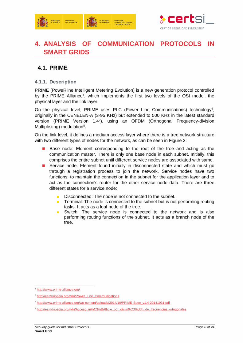
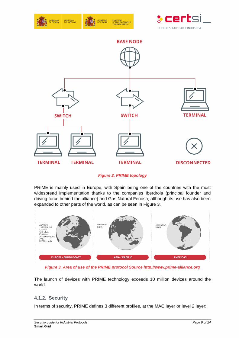
On the link level, it defines a medium access layer where there is a tree network structure
with two different types of nodes for the network, as can be seen in Figure 2:
Base node: Element corresponding to the root of the tree and acting as the
communication master. There is only one base node in each subnet. Initially, this
comprises the entire subnet until different service nodes are associated with same.
Service node: Element found initially in disconnected state and which must go
through a registration process to join the network. Service nodes have two
functions: to maintain the connection in the subnet for the application layer and to
act as the connection's router for the other service node data. There are three
different states for a service node:
Disconnected: The node is not connected to the subnet. Terminal: The node is connected to the subnet but is not performing routing
tasks. It acts as a leaf node of the tree. Switch: The service node is connected to the network and is also
performing routing functions of the subnet. It acts as a branch node of the tree.
5 http://www.prime-alliance.org/
6 http://es.wikipedia.org/wiki/Power_Line_Communications
7 http://www.prime-alliance.org/wp-content/uploads/2014/10/PRIME-Spec_v1.4-20141031.pdf
8 http://es.wikipedia.org/wiki/Acceso_m%C3%BAltiple_por_divisi%C3%B3n_de_frecuencias_ortogonales
Security guide for Industrial Protocols Page 9 of 24
Smart Grid
Figure 2. PRIME topology
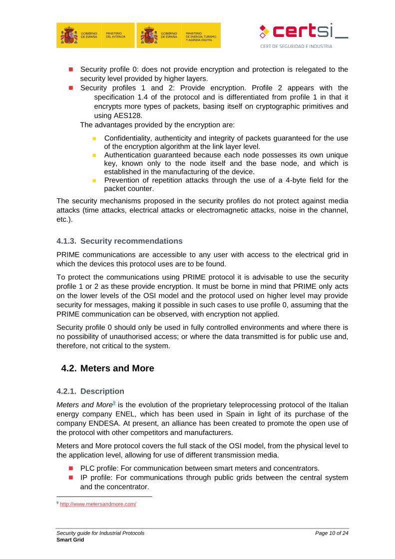
PRIME is mainly used in Europe, with Spain being one of the countries with the most
widespread implementation thanks to the companies Iberdrola (principal founder and
driving force behind the alliance) and Gas Natural Fenosa, although its use has also been
expanded to other parts of the world, as can be seen in Figure 3.
Figure 3. Area of use of the PRIME protocol Source http://www.prime-alliance.org
The launch of devices with PRIME technology exceeds 10 million devices around the
world.
4.1.2. Security
In terms of security, PRIME defines 3 different profiles, at the MAC layer or level 2 layer:
Security guide for Industrial Protocols Page 10 of 24
Smart Grid
Security profile 0: does not provide encryption and protection is relegated to the
security level provided by higher layers.
Security profiles 1 and 2: Provide encryption. Profile 2 appears with the
specification 1.4 of the protocol and is differentiated from profile 1 in that it
encrypts more types of packets, basing itself on cryptographic primitives and
using AES128.
The advantages provided by the encryption are:
Confidentiality, authenticity and integrity of packets guaranteed for the use of the encryption algorithm at the link layer level.
Authentication guaranteed because each node possesses its own unique key, known only to the node itself and the base node, and which is established in the manufacturing of the device.
Prevention of repetition attacks through the use of a 4-byte field for the packet counter.
The security mechanisms proposed in the security profiles do not protect against media
attacks (time attacks, electrical attacks or electromagnetic attacks, noise in the channel,
etc.).
4.1.3. Security recommendations
PRIME communications are accessible to any user with access to the electrical grid in
which the devices this protocol uses are to be found.
To protect the communications using PRIME protocol it is advisable to use the security
profile 1 or 2 as these provide encryption. It must be borne in mind that PRIME only acts
on the lower levels of the OSI model and the protocol used on higher level may provide
security for messages, making it possible in such cases to use profile 0, assuming that the
PRIME communication can be observed, with encryption not applied.
Security profile 0 should only be used in fully controlled environments and where there is
no possibility of unauthorised access; or where the data transmitted is for public use and,
therefore, not critical to the system.
4.2. Meters and More
4.2.1. Description
Meters and More9 is the evolution of the proprietary teleprocessing protocol of the Italian
energy company ENEL, which has been used in Spain in light of its purchase of the
company ENDESA. At present, an alliance has been created to promote the open use of
the protocol with other competitors and manufacturers.
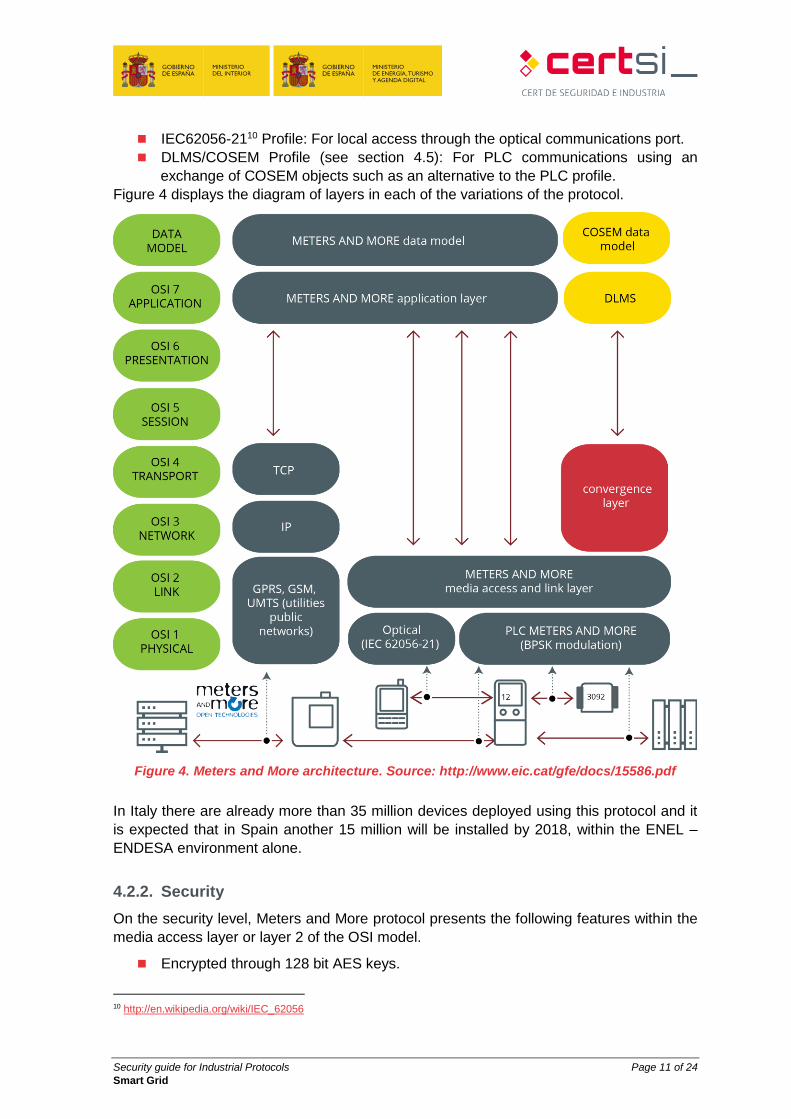
Meters and More protocol covers the full stack of the OSI model, from the physical level to
the application level, allowing for use of different transmission media.
PLC profile: For communication between smart meters and concentrators.
IP profile: For communications through public grids between the central system
and the concentrator.
9 http://www.metersandmore.com/
Security guide for Industrial Protocols Page 11 of 24
Smart Grid
IEC62056-2110 Profile: For local access through the optical communications port.
DLMS/COSEM Profile (see section 4.5): For PLC communications using an
exchange of COSEM objects such as an alternative to the PLC profile.
Figure 4 displays the diagram of layers in each of the variations of the protocol.
Figure 4. Meters and More architecture. Source: http://www.eic.cat/gfe/docs/15586.pdf
In Italy there are already more than 35 million devices deployed using this protocol and it
is expected that in Spain another 15 million will be installed by 2018, within the ENEL –
ENDESA environment alone.
4.2.2. Security
On the security level, Meters and More protocol presents the following features within the
media access layer or layer 2 of the OSI model.
Encrypted through 128 bit AES keys.
10 http://en.wikipedia.org/wiki/IEC_62056
Security guide for Industrial Protocols Page 12 of 24
Smart Grid
Authentication based on symmetric keys.
Protection against retransmission attacks.
Checking of message integrity.
Individual keys for each meter, with access control (reading/writing).
End-to-End protection.
Messages are encrypted and authenticated through the same key.
4.2.3. Security recommendations
The Meters and More protocol incorporates security features into its design, meaning that
its use is advisable provided those features are used appropriately.
Focussing on the joint use of Meters and More with DLMS/COSEM, all security should not
be left to this second protocol, and security measures of Meters and More itself ought to
be used also.
In mixed environments where the protocols commented on are used jointly, it is
recommended that all the security measures of Meters and More are applied to those
additional security features provided by DLMS/COSEM (see section 4.5.2 and section
4.5.3).
4.3. G3-PLC
4.3.1. Description
G3-PLC11 is a standard international open protocol developed specifically for smart grids
by Sagem12, ERDF13 and Maxim14, which operates at low frequency, below 500 kHz,
promoting the interoperability between 10 kHz and 490 kHz in their communication. It
supports different modulations of OFDM and consists of a highly reliable protocol with
bidirectional communication. The G3-PLC specification includes the physical and link
layers (MAC), where it is supported on OFDM, and a 6LoWPAN15 adaptation layer to
transmit IPv6 packets through the network. These characteristics ensure that this protocol
is designed for infrastructures with multiple nodes on a large scale.
The protocol is promoted by the French distribution system operator (ERDF).
The following are some of the features of this protocol:
Robustness and a wide range of communication frequencies that provide a great
advantage when it comes to installing smart devices that send data to the
concentrators.
Design that allows for end-to-end communication through IPv6.
11 http://www.g3-plc.com/
12 http://www.sagem.com/
13 http://www.erdf.fr/
14 http://www.maximintegrated.com/
15 https://es.wikipedia.org/wiki/6LoWPAN
Security guide for Industrial Protocols Page 13 of 24
Smart Grid
It uses the bands defined by CENELEC16, FCC17 and ARIB18:
Section 15 of the FCC rules establishes that the frequency of the band for PLC in North America must be between 10 and 490 kHz.
ARIB establishes that the frequency for the PLC band in Asia must be between 10 and 450 kHz.
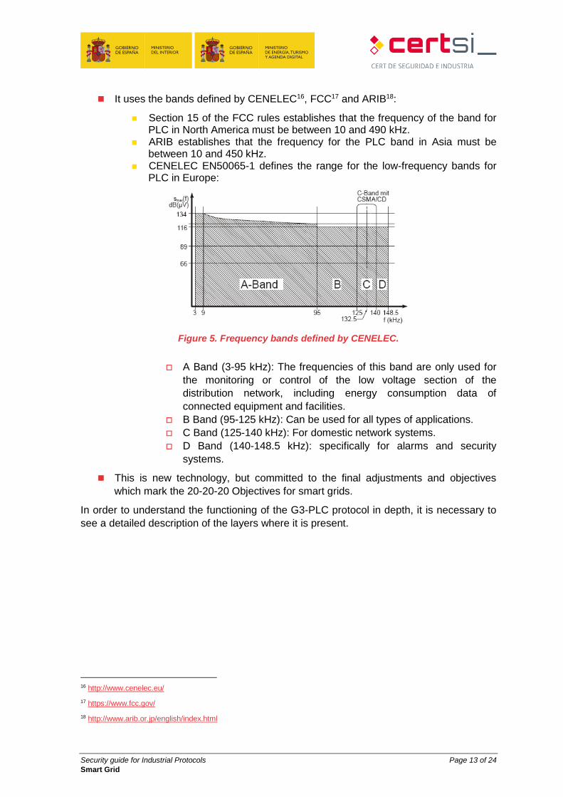
CENELEC EN50065-1 defines the range for the low-frequency bands for PLC in Europe:
Figure 5. Frequency bands defined by CENELEC.
A Band (3-95 kHz): The frequencies of this band are only used for
the monitoring or control of the low voltage section of the
distribution network, including energy consumption data of
connected equipment and facilities.
B Band (95-125 kHz): Can be used for all types of applications.
C Band (125-140 kHz): For domestic network systems.
D Band (140-148.5 kHz): specifically for alarms and security
systems.
This is new technology, but committed to the final adjustments and objectives
which mark the 20-20-20 Objectives for smart grids.
In order to understand the functioning of the G3-PLC protocol in depth, it is necessary to
see a detailed description of the layers where it is present.
16 http://www.cenelec.eu/
17 https://www.fcc.gov/
18 http://www.arib.or.jp/english/index.html
Security guide for Industrial Protocols Page 14 of 24
Smart Grid
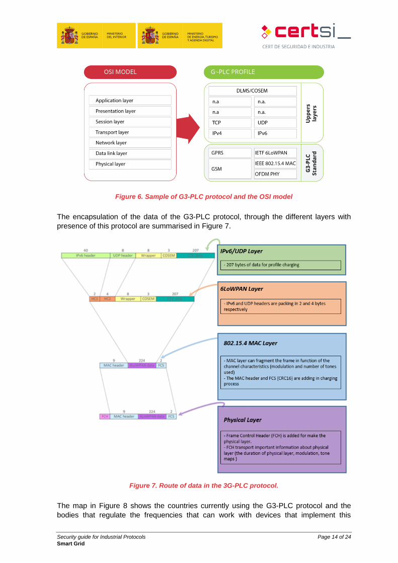
Figure 6. Sample of G3-PLC protocol and the OSI model
The encapsulation of the data of the G3-PLC protocol, through the different layers with
presence of this protocol are summarised in Figure 7.
Figure 7. Route of data in the 3G-PLC protocol.
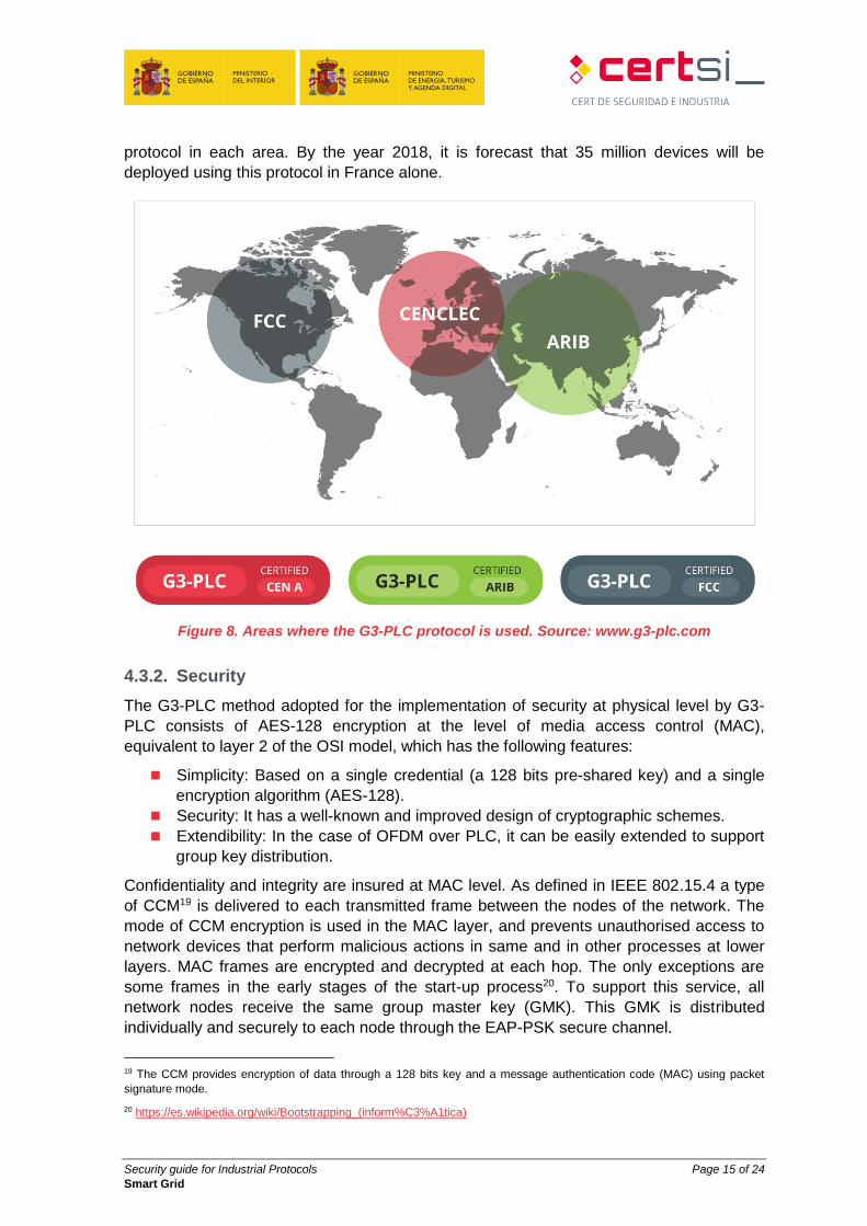
The map in Figure 8 shows the countries currently using the G3-PLC protocol and the
bodies that regulate the frequencies that can work with devices that implement this
Security guide for Industrial Protocols Page 15 of 24
Smart Grid
protocol in each area. By the year 2018, it is forecast that 35 million devices will be
deployed using this protocol in France alone.
Figure 8. Areas where the G3-PLC protocol is used. Source: www.g3-plc.com
4.3.2. Security
The G3-PLC method adopted for the implementation of security at physical level by G3-
PLC consists of AES-128 encryption at the level of media access control (MAC),
equivalent to layer 2 of the OSI model, which has the following features:
Simplicity: Based on a single credential (a 128 bits pre-shared key) and a single
encryption algorithm (AES-128).
Security: It has a well-known and improved design of cryptographic schemes.
Extendibility: In the case of OFDM over PLC, it can be easily extended to support
group key distribution.
Confidentiality and integrity are insured at MAC level. As defined in IEEE 802.15.4 a type
of CCM19 is delivered to each transmitted frame between the nodes of the network. The
mode of CCM encryption is used in the MAC layer, and prevents unauthorised access to
network devices that perform malicious actions in same and in other processes at lower
layers. MAC frames are encrypted and decrypted at each hop. The only exceptions are
some frames in the early stages of the start-up process20. To support this service, all
network nodes receive the same group master key (GMK). This GMK is distributed
individually and securely to each node through the EAP-PSK secure channel.
19 The CCM provides encryption of data through a 128 bits key and a message authentication code (MAC) using packet
signature mode.
20 https://es.wikipedia.org/wiki/Bootstrapping_(inform%C3%A1tica)
Security guide for Industrial Protocols Page 16 of 24
Smart Grid
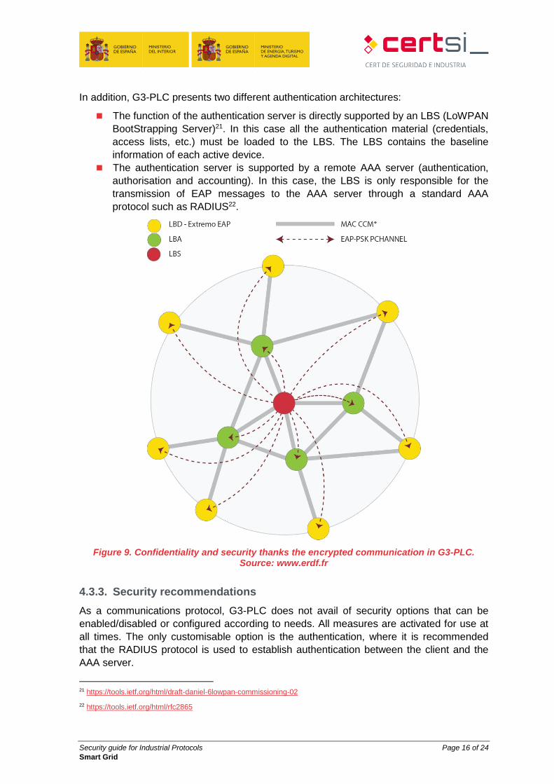
In addition, G3-PLC presents two different authentication architectures:
The function of the authentication server is directly supported by an LBS (LoWPAN
BootStrapping Server)21. In this case all the authentication material (credentials,
access lists, etc.) must be loaded to the LBS. The LBS contains the baseline
information of each active device.
The authentication server is supported by a remote AAA server (authentication,
authorisation and accounting). In this case, the LBS is only responsible for the
transmission of EAP messages to the AAA server through a standard AAA
protocol such as RADIUS22.
Figure 9. Confidentiality and security thanks the encrypted communication in G3-PLC. Source: www.erdf.fr
4.3.3. Security recommendations
As a communications protocol, G3-PLC does not avail of security options that can be
enabled/disabled or configured according to needs. All measures are activated for use at
all times. The only customisable option is the authentication, where it is recommended
that the RADIUS protocol is used to establish authentication between the client and the
AAA server.
21 https://tools.ietf.org/html/draft-daniel-6lowpan-commissioning-02
22 https://tools.ietf.org/html/rfc2865
Security guide for Industrial Protocols Page 17 of 24
Smart Grid
Outside the protocol itself, it is recommended that there is correct filtering of information
that arrives through the PLC networks.
As G3-PLC only implements the low levels of the OSI model, another product must be
used for the higher levels. These higher level protocols must also have the security
features available activated.
4.4. OSGP
4.4.1. Description
The Open Smart Grid Protocol (OSGP) currently applied in various countries on large
scale Smart Metering projects. It was developed by OSGP Alliance23 and published as a
standard by the European Telecommunications Standards Institute (ETSI). It is one of the
most used and tried protocols in the field of meters and smart networks and there are
currently more than 100 million devices that support it across the world.
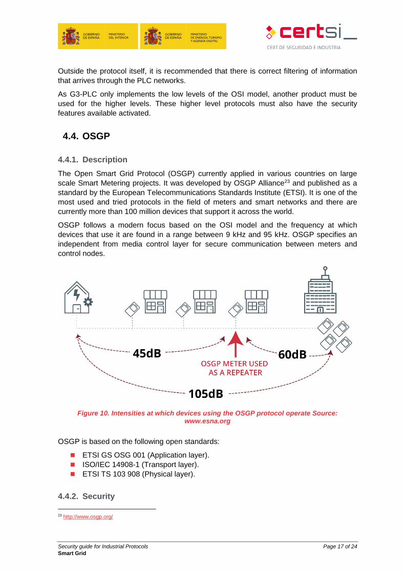
OSGP follows a modern focus based on the OSI model and the frequency at which
devices that use it are found in a range between 9 kHz and 95 kHz. OSGP specifies an
independent from media control layer for secure communication between meters and
control nodes.
Figure 10. Intensities at which devices using the OSGP protocol operate Source: www.esna.org
OSGP is based on the following open standards:
ETSI GS OSG 001 (Application layer).
ISO/IEC 14908-1 (Transport layer).
ETSI TS 103 908 (Physical layer).
4.4.2. Security
23 http://www.osgp.org/
Security guide for Industrial Protocols Page 18 of 24
Smart Grid
The security measures are included to protect the privacy of consumers by restricting
access to data, using encryption of these data to prevent unauthorised access. The
security measures are also included to detect attempts to elude other functions, such as,
for example, not performing measurements correctly and preventing the sending of
reading data to the concentrator.
Detailed below are the four security features of the protocol:
RC4 algorithm: Flow encryption system between points that convert plain text in bit
to bit encrypted text. The implementation of the RC4 algorithm in OSGP is similar
to that used in WEP and has similar weaknesses.
Response function: OSGP implements a response function to use with the
authentication message.
Secure Broadcast: A mechanism used to send firmware updates.
Keys: The protocol uses session keys to encrypt messages and a master key for
identification.
4.4.3. Security recommendations
The security features incorporated within the OSGP protocol do not provide all the
security that might be assumed.
The implementation of the RC4 algorithm maintains the weaknesses detected in
the WEP protocol and is considered an insecure algorithm.
The hash function (digest) produces an output of 8 bytes in length and is
generated through a byte-to-byte process in linear format, limiting the entropy of
the process. The weakness of this protocol allows a manipulation of the responses
generated.
The distribution of firmware through “Secure Broadcast” is made without any
specific measure to authenticate the origin.
The master key used for authentication is also used to provide the session keys.
Due to these shortcomings in the protocol's own security measures, it is recommended
that external security measures are used to ensure communications made through OSGP
such as the use of encryption tools for the robust encryption of end-to-end PLC
communications or the use of filtering in PLC communications between meters and the
concentrator.
4.5. DLMS/COSEM
4.5.1. Description
DLMS/COSEM24 is an application level protocol that defines from layer 4 to layer 7 of the
OSI model. The initials that give their name to the protocol stand for the following
DLMS: “Device Language Message Specification”, a generalised concept for an
abstract model of communication entities.
24 http://www.dlms.com/
Security guide for Industrial Protocols Page 19 of 24
Smart Grid
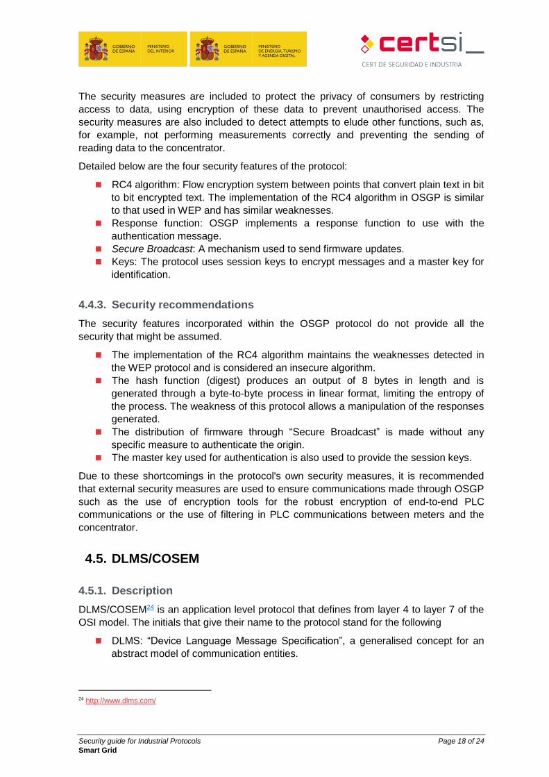
COSEM: “Companion Specification for Energy Metering”, sets the rules, based on
standards, for the exchange of information with energy meters.
This protocol is regulated by the standard IEC 6205625.
Figure 11. Model of DLMS/COSEM layers
The DLMS/COSEM protocol was developed to be used jointly with the PRIME protocol,
which operates on the lower levels of the OSI model and on network level protocols
(IPv4/IPv6). Thus, communication is permitted with low level devices, such as smart
meters, and communication with systems with more resources, such as the control centre
equipment. There is also the possibility of using this protocol jointly with "Meters and
More" protocol.
25 http://www.dlms.com/documentation/dlmscosemspecification/iecstandardsforelectricitymetering.html
Security guide for Industrial Protocols Page 20 of 24
Smart Grid
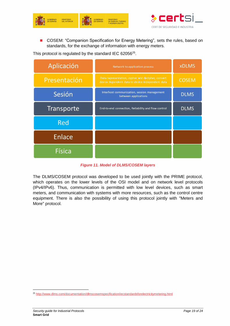
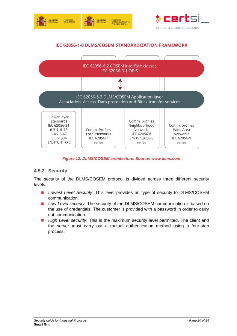
Figure 12. DLMS/COSEM architecture. Source: www.dlms.com
4.5.2. Security
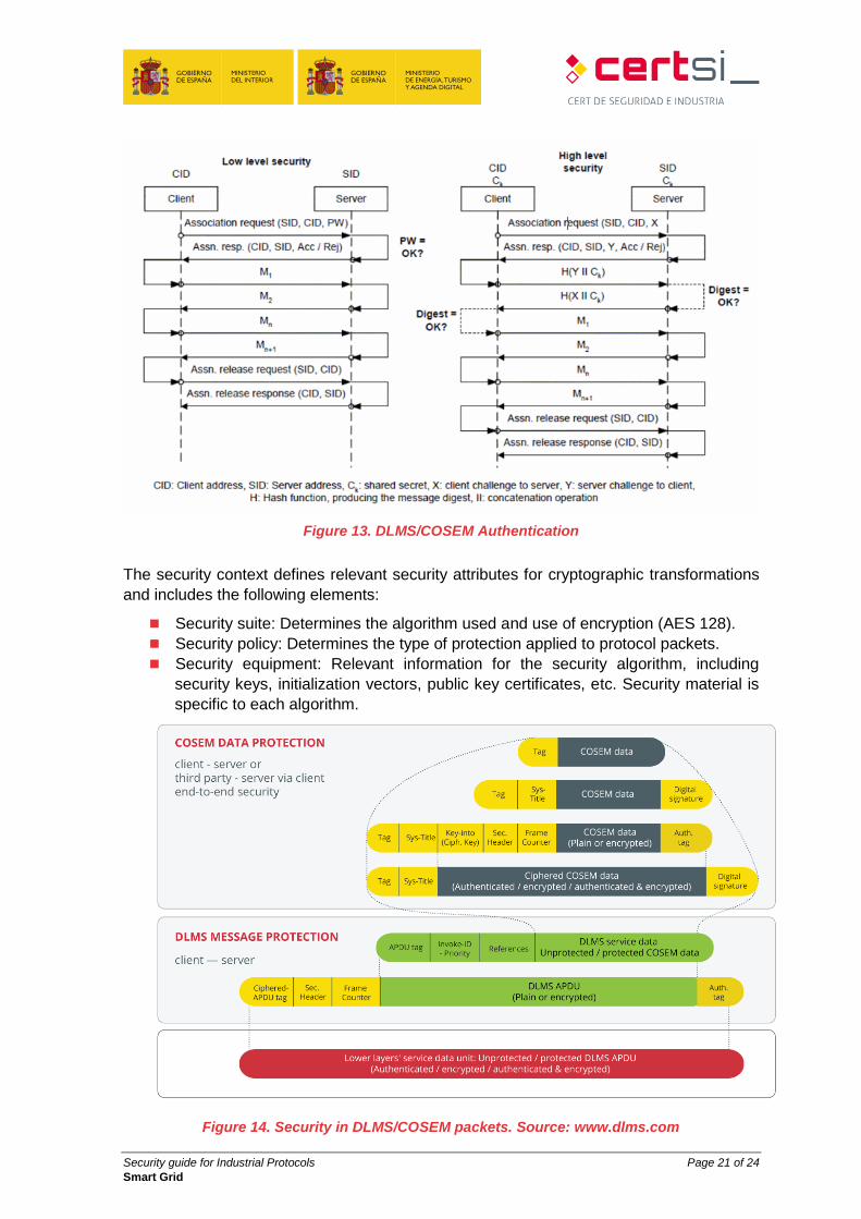
The security of the DLMS/COSEM protocol is divided across three different security
levels.
Lowest Level Security: This level provides no type of security to DLMS/COSEM
communication.
Low Level security: The security of the DLMS/COSEM communication is based on
the use of credentials. The customer is provided with a password in order to carry
out communication.
High Level security: This is the maximum security level permitted. The client and
the server must carry out a mutual authentication method using a four-step
process.
Security guide for Industrial Protocols Page 21 of 24
Smart Grid
Figure 13. DLMS/COSEM Authentication
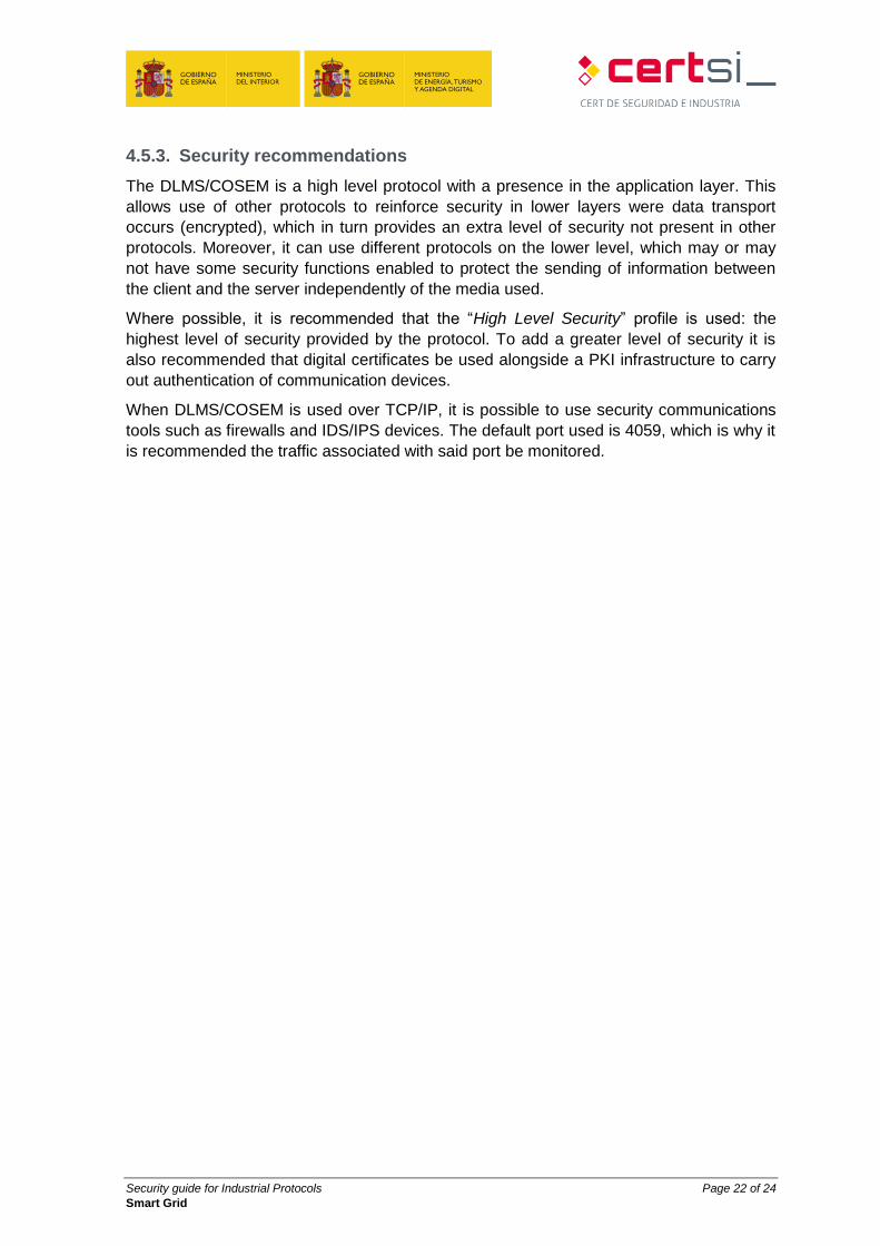
The security context defines relevant security attributes for cryptographic transformations
and includes the following elements:
Security suite: Determines the algorithm used and use of encryption (AES 128).
Security policy: Determines the type of protection applied to protocol packets.
Security equipment: Relevant information for the security algorithm, including
security keys, initialization vectors, public key certificates, etc. Security material is
specific to each algorithm.
Figure 14. Security in DLMS/COSEM packets. Source: www.dlms.com
Security guide for Industrial Protocols Page 22 of 24
Smart Grid
4.5.3. Security recommendations
The DLMS/COSEM is a high level protocol with a presence in the application layer. This
allows use of other protocols to reinforce security in lower layers were data transport
occurs (encrypted), which in turn provides an extra level of security not present in other
protocols. Moreover, it can use different protocols on the lower level, which may or may
not have some security functions enabled to protect the sending of information between
the client and the server independently of the media used.
Where possible, it is recommended that the “High Level Security” profile is used: the
highest level of security provided by the protocol. To add a greater level of security it is
also recommended that digital certificates be used alongside a PKI infrastructure to carry
out authentication of communication devices.
When DLMS/COSEM is used over TCP/IP, it is possible to use security communications
tools such as firewalls and IDS/IPS devices. The default port used is 4059, which is why it
is recommended the traffic associated with said port be monitored.
Security guide for Industrial Protocols Page 23 of 24
Smart Grid
5. COMPARISON SUMMARY TABLE
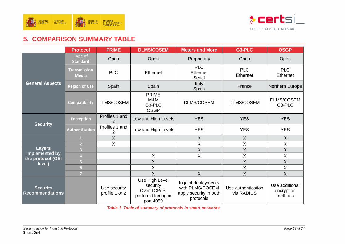
Protocol PRIME DLMS/COSEM Meters and More G3-PLC OSGP
General Aspects
Type of Standard
Open Open Proprietary Open Open
Transmission Media
PLC Ethernet PLC
Ethernet Serial
PLC Ethernet
PLC Ethernet
Region of Use Spain Spain Italy
Spain France Northern Europe
Compatibility DLMS/COSEM
PRIME M&M
G3-PLC OSGP
DLMS/COSEM DLMS/COSEM DLMS/COSEM
G3-PLC
Security
Encryption Profiles 1 and
2 Low and High Levels YES YES YES
Authentication Profiles 1 and
2 Low and High Levels YES YES YES
Layers implemented by the protocol (OSI
level)
1 X X X X
2 X X X X
3 X X X
4 X X X X
5 X X X
6 X X X
7 X X X X
Security Recommendations
Use security profile 1 or 2
Use High Level security
Over TCP/IP, perform filtering in
port 4059
In joint deployments with DLMS/COSEM
apply security in both protocols
Use authentication via RADIUS
Use additional encryption methods
Table 1. Table of summary of protocols in smart networks.

Security guide for Industrial Protocols Page 24 of 24
Smart Grid