Securing Switch Access
29
Securing Switch Access Switches direct and control much of the data flowing across computer networks. Conventional network security often focuses more on routers and blocking traffic from the outside. Switches are internal to the organization and designed to allow ease of connectivity, therefore only limited or no security measures are applied. Network Hierarchy In a well-formed hierarchical network, there are three defined layers: access, distribution and core. In an enterprise network, each layer provides different functions. Because these layers are not always recognized by their traditional names, the names have been referred to as access or workgroup, distribution or policy, and core or backbone. Figure 1 Network Hierarchy
-
Upload
netwax-lab -
Category
Technology
-
view
41 -
download
1
Transcript of Securing Switch Access

Securing Switch Access
Switches direct and control much of the data flowing across computer networks.
Conventional network security often focuses more on routers and blocking traffic from the outside.
Switches are internal to the organization and designed to allow ease of connectivity, therefore only
limited or no security measures are applied.
Network Hierarchy
In a well-formed hierarchical network, there are three defined layers: access, distribution and core. In an
enterprise network, each layer provides different functions. Because these layers are not always
recognized by their traditional names, the names have been referred to as access or workgroup,
distribution or policy, and core or backbone.
Figure 1 Network Hierarchy

Securing Switch Access
Configure Switch Security
1. Operating System
If an operating system on a switch is not kept current then the switch may be susceptible to information
gathering and network attacks. Attackers find weaknesses in versions of an operating system over time.
New security features are added to each new version of an operating system.
Install the latest stable version of the IOS on each Switch.
2. Passwords
One password is used for the enable password and the other will later be assigned to the console port.
SWITCH(config)#enable secret [password]
SWITCH(config)#username admin password [password]
A password should be required to access the console line. Even the basic user EXEC mode can provide
significant information to a malicious user. In addition, the VTY lines must have a password before users
can access the switch remotely.
SWITCH(coanfig)#line console 0
SWITCH(config-line)#password cisco
SWITCH(config-line)#login
SWITCH(config-line)#line vty 0 15
SWITCH(config-line)#password cisco
SWITCH(config-line)#login
SWITCH(config-line)#exit
At this stage, the privileged EXEC password is already encrypted. To encrypt the line passwords that you
just configured, enter the service password-encryption command in global configuration mode.
SWITCH(config)#service password-encryption
Set the exec-timeout period to 9 minutes or less to disconnect idle connections to the console line on
each switch. Do not set the timeout period to zero because on Cisco switches that will disable the
timeout. The following example sets the timeout period for the console line to 9 minutes and 0 seconds.
SWITCH(config)# line con 0
SWITCH(config-line)# exec-timeout 9 0
Configure the message-of-the-day (MOTD) using Authorized Access Only as the text. Follow these
guidelines:

Securing Switch Access
i. The banner text is case sensitive. Make sure you do not add any spaces before or after
the banner text.
ii. Use a delimiting character before and after the banner text to indicate where the text
begins and ends. The delimiting character used in the example below is %, but you can
use any character that is not used in the banner text.
iii. After you have configured the MOTD, log out of the switch to verify that the banner
displays when you log back in.
SWITCH(config)#banner motd %Authorized Access Only%
SWITCH(config)#end
SWITCH#exit
3. Network Services
Switches can have a number of network services enabled. Many of these services are typically not
necessary for a switch’s normal operation; however if these services are enabled then the switch may be
susceptible to information gathering or to network attacks. The characteristics or the poor configuration
of the network services on a switch can lead to compromise. Most of these services use one of the
following transport mechanisms at Layer 4 of the OSI RM: Transmission Control Protocol (TCP) and User
Datagram Protocol (UDP).
If possible, instead of using a network service (e.g., telnet) to perform in-band management of a switch,
use out-of-band management (e.g., via the console port) for each switch. Out-of-band management
reduces the exposure of configuration information and passwords better than in-band management.
3.1. Unnecessary Network Services
If possible, disable each unnecessary network service on each switch. The following
commands will disable services of concern. In some cases, the commands affect the switch
globally, while in other cases the commands affect only a single interface.
Below is an example for the set of interfaces that includes GigabitEthernet 6/1 through 6/3.
SWITCH(config)# interface range gigabitethernet 6/1 – 3
3.1.1. TCP and UDP Small Servers - TCP/UDP Ports 7, 9, 13, 19
Cisco provides support for “small servers” (e.g., echo, discard, daytime and chargen). Two of
these servers, echo and chargen, can be used in denial-of-service attacks against one or
more switches. These services can be disabled using the following commands.
SWITCH(config)# no service tcp-small-servers
SWITCH(config)# no service udp-small-servers

Securing Switch Access
3.1.2. Bootp Server - UDP Port 67
A Cisco switch can act as a bootp server to distribute system images to other Cisco systems.
Unless this is an operational requirement, it is best to disable this service with the following
command to minimize unauthorized access to the switch’s system image.
Switch(config)# no ip bootp server
3.1.3. Finger - TCP Port 79
Cisco switches support the finger service, which can provide information about users
currently logged onto the switch. Either of the following commands will disable finger
service. The first command will replace the second command in future versions of IOS.
Switch(config)# no ip finger
Switch(config)# no service finger
3.1.4. Configuration Autoload
A Cisco switch can obtain its configuration from a network server via a few methods. These
methods are not recommended because configuration information is passed in cleartext
during the boot process and can be collected by unauthorized users. Use the following
commands to disable these methods.
Switch(config)# no service config
Switch(config)# no boot host
Switch(config)# no boot network
Switch(config)# no boot system
3.1.5. Packet Assembler/Disassembler (PAD)
PAD enables X.25 connections between network systems. Unless a network requires this
capability the PAD service should be disabled with the following command.
Switch(config)# no service pad
3.1.6. Address Resolution Protocol (ARP)
Normally, ARP messages are confined to a single broadcast domain, but a switch can proxy
ARP messages from one domain to another. Unless a switch is required to be an
intermediary for ARP requests, this feature should be disabled with the following commands
on each interface where it is not required.
Switch(config-if)# no ip proxy-arp

Securing Switch Access
3.1.7. Internet Control Message Protocol (ICMP) Messages
A Cisco switch can generate automatically three types of ICMP messages: Host Unreachable,
Redirect and Mask Reply. The Mask Reply message provides the subnet mask for a particular
network to the requestor. An attacker can use these messages to aid in mapping a network.
Disabling these messages with the following commands is recommended for each interface
and for the Null 0 interface.
Switch(config-if)# no ip unreachables
Switch(config-if)# no ip redirects
Switch(config-if)# no ip mask-reply
The Null 0 interface deserves particular attention. This interface is a packet sink. It is
sometimes utilized in denial-of-service attack prevention and all blocked packets are
forwarded to this interface. It will generate Host Unreachable messages that could flood the
network unless the facility is disabled. Attackers might also be able to use these messages to
determine access-control list configuration by identifying blocked packets.
Directed broadcasts allow broadcast messages initiated from different broadcast domains
than are locally attached to the switch. For example, attackers have used ICMP directed
broadcasts for this purpose. It is recommended that this broadcast capability be turned off,
using the following command on each interface.
Switch(config-if)# no ip directed-broadcast
3.2. Potentially Necessary Network Services
Certain network services may be necessary for the administration of a switch. If in-band
management or a specific network service is necessary, then consider the following
subsections for configuring network services more securely.
Set up a unique account for each administrator for access to any necessary network service.
The following commands present an example that creates an account (e.g., ljones) with a
privilege level (e.g., 0). This account is local to the switch only. Privilege level 0 is the lowest
level on Cisco switches and allows a very small set of commands. The administrator can go to
a higher level (e.g., 15) from level 0 using the enable command.
Switch(config)# username ljones privilege 0
Switch(config)# username ljones secret g00d-P5WD
Securing Switch Access
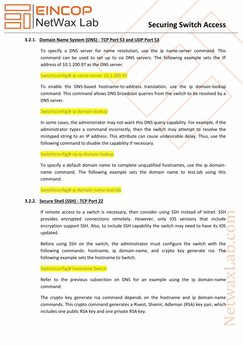
3.2.1. Domain Name System (DNS) - TCP Port 53 and UDP Port 53
To specify a DNS server for name resolution, use the ip name-server command. This
command can be used to set up to six DNS servers. The following example sets the IP
address of 10.1.200.97 as the DNS server.
Switch(config)# ip name-server 10.1.200.97
To enable the DNS-based hostname-to-address translation, use the ip domain-lookup
command. This command allows DNS broadcast queries from the switch to be resolved by a
DNS server.
Switch(config)# ip domain-lookup
In some cases, the administrator may not want this DNS query capability. For example, if the
administrator types a command incorrectly, then the switch may attempt to resolve the
mistyped string to an IP address. This attribute can cause undesirable delay. Thus, use the
following command to disable the capability if necessary.
Switch(config)# no ip domain-lookup
To specify a default domain name to complete unqualified hostnames, use the ip domain-
name command. The following example sets the domain name to test.lab using this
command.
Switch(config)# ip domain-name test.lab
3.2.2. Secure Shell (SSH) - TCP Port 22
If remote access to a switch is necessary, then consider using SSH instead of telnet. SSH
provides encrypted connections remotely. However, only IOS versions that include
encryption support SSH. Also, to include SSH capability the switch may need to have its IOS
updated.
Before using SSH on the switch, the administrator must configure the switch with the
following commands: hostname, ip domain-name, and crypto key generate rsa. The
following example sets the hostname to Switch.
Switch(config)# hostname Switch
Refer to the previous subsection on DNS for an example using the ip domain-name
command.
The crypto key generate rsa command depends on the hostname and ip domain-name
commands. This crypto command generates a Rivest, Shamir, Adleman (RSA) key pair, which
includes one public RSA key and one private RSA key.
Securing Switch Access
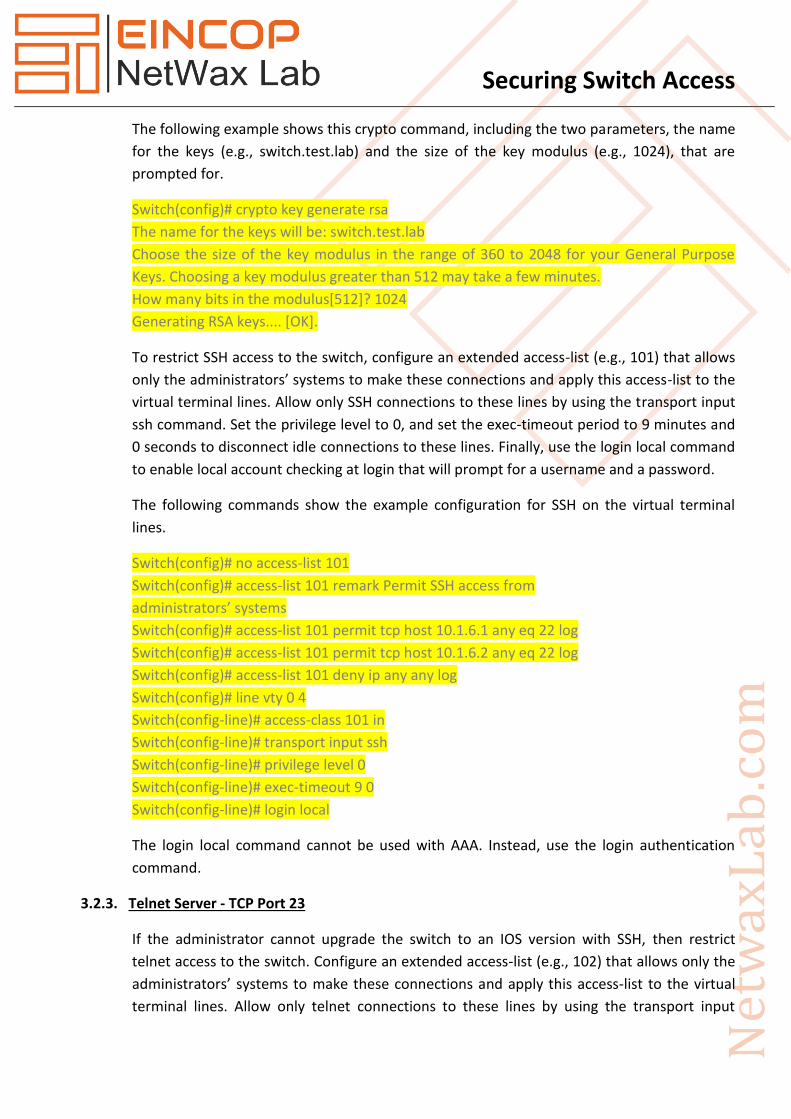
The following example shows this crypto command, including the two parameters, the name
for the keys (e.g., switch.test.lab) and the size of the key modulus (e.g., 1024), that are
prompted for.
Switch(config)# crypto key generate rsa
The name for the keys will be: switch.test.lab
Choose the size of the key modulus in the range of 360 to 2048 for your General Purpose
Keys. Choosing a key modulus greater than 512 may take a few minutes.
How many bits in the modulus[512]? 1024
Generating RSA keys.... [OK].
To restrict SSH access to the switch, configure an extended access-list (e.g., 101) that allows
only the administrators’ systems to make these connections and apply this access-list to the
virtual terminal lines. Allow only SSH connections to these lines by using the transport input
ssh command. Set the privilege level to 0, and set the exec-timeout period to 9 minutes and
0 seconds to disconnect idle connections to these lines. Finally, use the login local command
to enable local account checking at login that will prompt for a username and a password.
The following commands show the example configuration for SSH on the virtual terminal
lines.
Switch(config)# no access-list 101
Switch(config)# access-list 101 remark Permit SSH access from
administrators’ systems
Switch(config)# access-list 101 permit tcp host 10.1.6.1 any eq 22 log
Switch(config)# access-list 101 permit tcp host 10.1.6.2 any eq 22 log
Switch(config)# access-list 101 deny ip any any log
Switch(config)# line vty 0 4
Switch(config-line)# access-class 101 in
Switch(config-line)# transport input ssh
Switch(config-line)# privilege level 0
Switch(config-line)# exec-timeout 9 0
Switch(config-line)# login local
The login local command cannot be used with AAA. Instead, use the login authentication
command.
3.2.3. Telnet Server - TCP Port 23
If the administrator cannot upgrade the switch to an IOS version with SSH, then restrict
telnet access to the switch. Configure an extended access-list (e.g., 102) that allows only the
administrators’ systems to make these connections and apply this access-list to the virtual
terminal lines. Allow only telnet connections to these lines by using the transport input

Securing Switch Access
telnet command. Set the privilege level to 0, and set the exec-timeout period to 9 minutes
and 0 seconds to disconnect idle connections to these lines. Finally, use the login local
command to enable local account checking at login that will prompt for a username and a
password.
The following commands show the example configuration for telnet on the virtual terminal
lines.
Switch(config)# no access-list 102
Switch(config)# access-list 102 remark Permit telnet access from
administrators’ systems
Switch(config)# access-list 102 permit tcp host 10.1.6.1 any eq 23 log
Switch(config)# access-list 102 permit tcp host 10.1.6.2 any eq 23 log
Switch(config)# access-list 102 deny ip any any log
Switch(config)# line vty 0 4
Switch(config-line)# access-class 102 in
Switch(config-line)# transport input telnet
Switch(config-line)# privilege level 0
Switch(config-line)# exec-timeout 9 0
Switch(config-line)# login local
The login local command cannot be used with AAA. Instead, use the login authentication
command.
3.2.4. Hyper Text Transfer Protocol (HTTP) - TCP Port 80
An HTTP server is included in IOS to allow remote administration of the switch through a
web interface. If web-based administration of the switch is not necessary, then disable the
HTTP server using the following command.
Switch(config)# no ip http server
3.2.5. Simple Network Management Protocol (SNMP) - UDP Ports 161, 162
SNMP is a service used to perform network management functions using a data structure
called a Management Information Base (MIB). Unfortunately, SNMP version 1 is widely
implemented but not very secure, using only clear-text community strings for access to
information on the switch, including its configuration file.
If SNMP is not being used, then executing the following commands will disable the service:
Switch(config)# no snmp-server community
Switch(config)# no snmp-server enable traps
Switch(config)# no snmp-server system-shutdown
Securing Switch Access
Switch(config)# no snmp-server
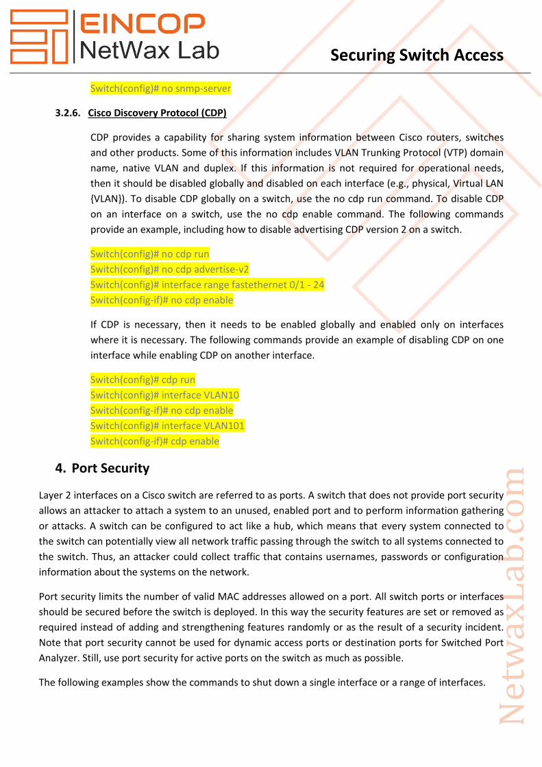
3.2.6. Cisco Discovery Protocol (CDP)
CDP provides a capability for sharing system information between Cisco routers, switches
and other products. Some of this information includes VLAN Trunking Protocol (VTP) domain
name, native VLAN and duplex. If this information is not required for operational needs,
then it should be disabled globally and disabled on each interface (e.g., physical, Virtual LAN
{VLAN}). To disable CDP globally on a switch, use the no cdp run command. To disable CDP
on an interface on a switch, use the no cdp enable command. The following commands
provide an example, including how to disable advertising CDP version 2 on a switch.
Switch(config)# no cdp run
Switch(config)# no cdp advertise-v2
Switch(config)# interface range fastethernet 0/1 - 24
Switch(config-if)# no cdp enable
If CDP is necessary, then it needs to be enabled globally and enabled only on interfaces
where it is necessary. The following commands provide an example of disabling CDP on one
interface while enabling CDP on another interface.
Switch(config)# cdp run
Switch(config)# interface VLAN10
Switch(config-if)# no cdp enable
Switch(config)# interface VLAN101
Switch(config-if)# cdp enable
4. Port Security
Layer 2 interfaces on a Cisco switch are referred to as ports. A switch that does not provide port security
allows an attacker to attach a system to an unused, enabled port and to perform information gathering
or attacks. A switch can be configured to act like a hub, which means that every system connected to
the switch can potentially view all network traffic passing through the switch to all systems connected to
the switch. Thus, an attacker could collect traffic that contains usernames, passwords or configuration
information about the systems on the network.
Port security limits the number of valid MAC addresses allowed on a port. All switch ports or interfaces
should be secured before the switch is deployed. In this way the security features are set or removed as
required instead of adding and strengthening features randomly or as the result of a security incident.
Note that port security cannot be used for dynamic access ports or destination ports for Switched Port
Analyzer. Still, use port security for active ports on the switch as much as possible.
The following examples show the commands to shut down a single interface or a range of interfaces.

Securing Switch Access
Single interface:
Switch(config)# interface fastethernet 0/1
Switch(config-if)# shutdown
Range of interfaces:
Switch(config)# interface range fastethernet 0/2 - 8
Switch(config-if-range)# shutdown
The administrator can enable aging for statically configured MAC addresses on a port using the
switchport port-security aging static command. The aging time command (e.g., switchport port-security
aging time time) can be set in terms of minutes. Also, the aging type command can be set for inactivity
(e.g., switchport port-security aging type inactivity), which means that the addresses on the configured
port age out only if there is no data traffic from these addresses for the period defined by the aging time
command. This feature allows continuous access to a limited number of addresses.
The following example shows the commands for restricting a port statically on a Catalyst 3550 switch.
Switch(config-if)# switchport port-security
Switch(config-if)# switchport port-security violation shutdown
Switch(config-if)# switchport port-security maximum 1
Switch(config-if)# switchport port-security mac-address 0000.0200.0088
Switch(config-if)# switchport port-security aging time 10
Switch(config-if)# switchport port-security aging type inactivity
To restrict a port dynamically on a Catalyst 3550 switch use the following commands. Note that the
aging commands cannot be used with sticky MAC addresses.
Switch(config-if)# switchport port-security
Switch(config-if)# switchport port-security violation shutdown
Switch(config-if)# switchport port-security maximum 1
Switch(config-if)# switchport port-security mac-address sticky
Note that when a port security violation occurs, the port will immediately become error-disabled and its
LED will turn off. The switch also sends an SNMP trap, logs a syslog message and increments the
violation counter. When a port is in the error-disabled state, the administrator can bring it out of this
state by entering the errdisable recovery cause psecure-violation global configuration command or by
entering the shutdown and no shutdown interface configuration commands.
The following example creates a strict security macro called unused to secure the ports, or interfaces, on
a 3550 switch:
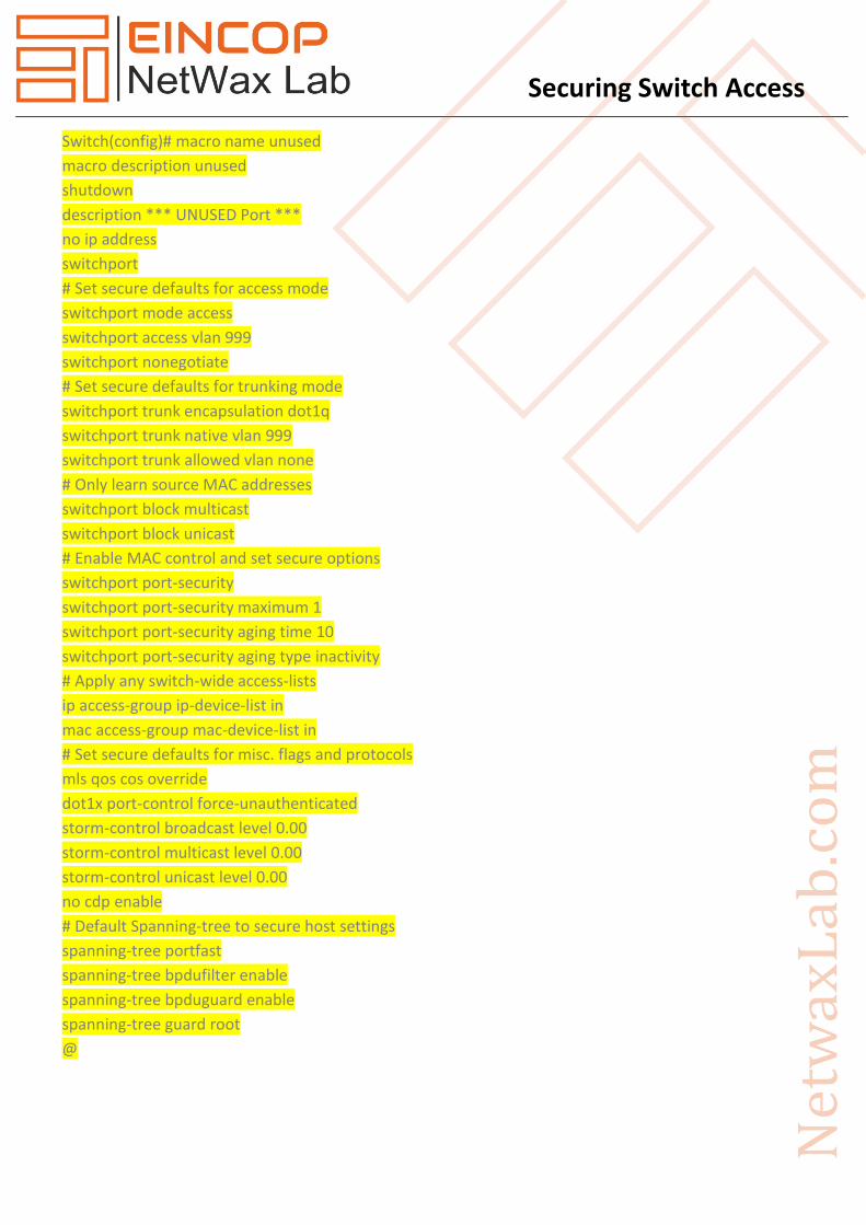
Securing Switch Access
Switch(config)# macro name unused
macro description unused
shutdown
description *** UNUSED Port ***
no ip address
switchport
# Set secure defaults for access mode
switchport mode access
switchport access vlan 999
switchport nonegotiate
# Set secure defaults for trunking mode
switchport trunk encapsulation dot1q
switchport trunk native vlan 999
switchport trunk allowed vlan none
# Only learn source MAC addresses
switchport block multicast
switchport block unicast
# Enable MAC control and set secure options
switchport port-security
switchport port-security maximum 1
switchport port-security aging time 10
switchport port-security aging type inactivity
# Apply any switch-wide access-lists
ip access-group ip-device-list in
mac access-group mac-device-list in
# Set secure defaults for misc. flags and protocols
mls qos cos override
dot1x port-control force-unauthenticated
storm-control broadcast level 0.00
storm-control multicast level 0.00
storm-control unicast level 0.00
no cdp enable
# Default Spanning-tree to secure host settings
spanning-tree portfast
spanning-tree bpdufilter enable
spanning-tree bpduguard enable
spanning-tree guard root
@

Securing Switch Access
After creating this strict security macro, unused, apply the macro to all switch ports as a secure baseline
with the following commands:
Switch(config)# interface range fasteth0/1 – 24 , giga0/1 – 2
Switch(config-if-range)# macro apply unused
5. System Availability
Many attacks exist and more are being created that cause denial of service, either partially or
completely, to systems or networks. Switches are just as susceptible to these attacks. These attacks
focus on making resources (e.g., system processor, bandwidth) unavailable.
The following countermeasures will mitigate the vulnerabilities to system availability on each switch:
To prevent fast flooding attacks and to guarantee that even the lowest priority processes get
some processor time use the scheduler interval command. The following example sets the
maximum time before running the lowest priority process to 500 milliseconds access.
Switch(config)# scheduler interval 500
Another way to guarantee processor time for processes is to use the scheduler allocate
command. This command sets the interrupt time and the process time
The following example makes 10 percent of the processor available for process tasks, with an
interrupt time of 4000 microseconds and a process time of 400 microseconds.
Switch(config)# scheduler allocate 4000 400
Use the following command on each interface to turn Flow Control off.
Switch(config-if)# flowcontrol receive off
UDLD should be disabled globally and on every interface where it is not required. To disable
UDLD globally use the following command.
Switch(config)# no udld enable
To disable UDLD on each interface use one of the following commands, depending on the switch
model and IOS version.
Switch(config-if)# no udld port
Switch(config-if)# udld disabled
To help prevent the SYN Flood attack the administrator can set the amount of time the switch
will wait while attempting to establish a TCP connection. The following command sets the wait
time to 10 seconds.
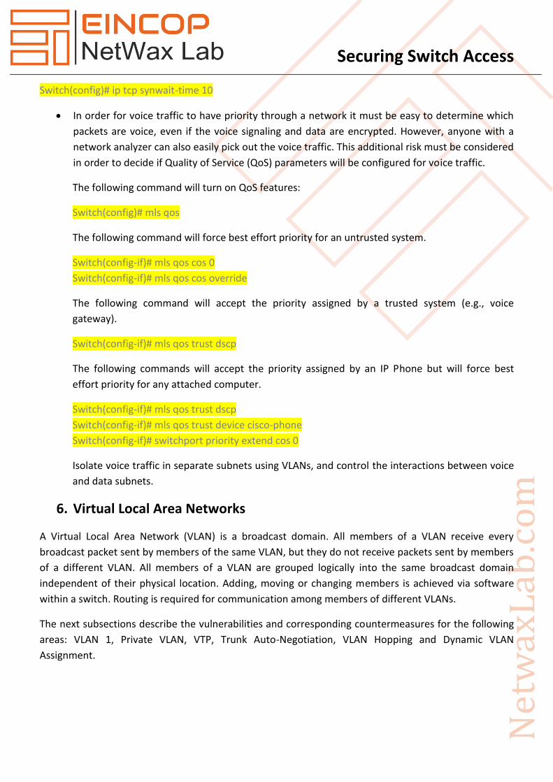
Securing Switch Access
Switch(config)# ip tcp synwait-time 10
In order for voice traffic to have priority through a network it must be easy to determine which
packets are voice, even if the voice signaling and data are encrypted. However, anyone with a
network analyzer can also easily pick out the voice traffic. This additional risk must be considered
in order to decide if Quality of Service (QoS) parameters will be configured for voice traffic.
The following command will turn on QoS features:
Switch(config)# mls qos
The following command will force best effort priority for an untrusted system.
Switch(config-if)# mls qos cos 0
Switch(config-if)# mls qos cos override
The following command will accept the priority assigned by a trusted system (e.g., voice
gateway).
Switch(config-if)# mls qos trust dscp
The following commands will accept the priority assigned by an IP Phone but will force best
effort priority for any attached computer.
Switch(config-if)# mls qos trust dscp
Switch(config-if)# mls qos trust device cisco-phone
Switch(config-if)# switchport priority extend cos 0
Isolate voice traffic in separate subnets using VLANs, and control the interactions between voice
and data subnets.
6. Virtual Local Area Networks
A Virtual Local Area Network (VLAN) is a broadcast domain. All members of a VLAN receive every
broadcast packet sent by members of the same VLAN, but they do not receive packets sent by members
of a different VLAN. All members of a VLAN are grouped logically into the same broadcast domain
independent of their physical location. Adding, moving or changing members is achieved via software
within a switch. Routing is required for communication among members of different VLANs.
The next subsections describe the vulnerabilities and corresponding countermeasures for the following
areas: VLAN 1, Private VLAN, VTP, Trunk Auto-Negotiation, VLAN Hopping and Dynamic VLAN
Assignment.

Securing Switch Access
6.1. VLAN1
Cisco switches use VLAN 1 as the default VLAN to assign to their ports, including their
management ports. Additionally, Layer 2 protocols, such as CDP and VTP, need to be sent on
a specific VLAN on trunk links, so VLAN 1 was selected. In some cases, VLAN 1 may span the
entire network if not appropriately pruned. It also provides attackers easier access and
extended reach for their attacks.
Do not use VLAN 1 for either out-of-band management or in-band management.
To provide out-of-band management that separates management traffic from user traffic,
use the following commands as an example.
Create the out-of-band management VLAN.
Switch(config)# vlan 6
Switch(config-vlan)# name ADMINISTRATION-VLAN
Create a management IP address and restrict access to it. Also, enable the interface.
Switch(config)# no access-list 10
Switch(config)# access-list 10 permit 10.1.6.1
Switch(config)# access-list 10 permit 10.1.6.2
Switch(config)# interface vlan 6
Switch(config-if)# description ADMIN-VLAN
Switch(config-if)# ip address 10.1.6.121 255.255.255.0
Switch(config-if)# ip access-group 10 in
Switch(config-if)# no shutdown
Assign the management VLAN to the dedicated interface.
Switch(config)# interface fastethernet 4/1
Switch(config-if)# description Out-Of-Band Admin
Switch(config-if)# switchport mode access
Switch(config-if)# switchport access vlan 6
Switch(config-if)# no shutdown
Ensure all trunk ports will not carry the management VLAN (e.g., 6).
Switch(config)# interface range gigabitethernet 6/15 - 16
Switch(config-if)# switchport trunk allowed vlan remove 6
Assigned the following name for VLAN 1.

Securing Switch Access
Switch# vlan 1
Switch(vlan)# name *** DEFAULT VLAN - Do NOT Use! ***
Assign all inactive interfaces to an unused VLAN other than VLAN 1 and shut down these
interfaces. Note that unused VLANs are not routable.
Switch# vlan 999
Switch(vlan)# name *** BIT BUCKET for unused ports ***
Switch(vlan)# shutdown
Switch(vlan)# exit
Switch(config)# interface range fastethernet 5/45 - 48
Switch(config-if)# switchport mode access
Switch(config-if)# switchport access vlan 999
Switch(config-if)# shutdown
Assign all interfaces to VLANs other than VLAN 1.
Switch(config)# interface fastethernet 0/1
Switch(config-if)# switchport mode access
Switch(config-if)# switchport access vlan 999
6.2. Private VLAN (PVLAN)
In certain instances where similar systems do not need to interact directly, PVLANs provide
additional protection. A primary PVLAN defines the broadcast domain with which the
secondary PVLANs are associated. The secondary PVLANs may either be isolated PVLANs or
community PVLANs. Hosts on isolated PVLANs communicate only with promiscuous ports,
and hosts on community PVLANs communicate only among themselves and with associated
promiscuous ports. This configuration provides fine-grained Layer 2 isolation control for
each system.
A configuration with multiple servers on a single VLAN should use PVLANs for Layer 2
separation among the servers. Routers should be on promiscuous ports and servers on an
isolated PVLAN. Only servers that need to communicate directly with other servers should
be on a community PVLAN. Implement VACLs on the primary PVLAN to filter traffic
originated by and routed to the same segment.
The following example creates a PVLAN with an NTP server on a promiscuous port and two
isolated servers.
Switch# vlan 200
Switch(vlan)# name SERVERS-PRIVATE
Switch(vlan)# private-vlan primary

Securing Switch Access
Switch(vlan)# private-vlan association 201
Switch# vlan 201
Switch(vlan)# name SERVERS-ISOLATED
Switch(vlan)# private-vlan isolated
Switch(config)# interface GigabitEthernet6/1
Switch(config-if)# description SERVER 1
Switch(config-if)# switchport private-vlan host-association 200 201
Switch(config-if)# switchport mode private-vlan host
Switch(config-if)# no shutdown
Switch(config)# interface GigabitEthernet6/2
Switch(config-if)# description SERVER 2
Switch(config-if)# switchport private-vlan host-association 200 201
Switch(config-if)# switchport mode private-vlan host
Switch(config-if)# no shutdown
Switch(config)# interface GigabitEthernet6/6
Switch(config-if)# description SERVER NTP Server
Switch(config-if)# switchport mode private-vlan promiscuous
Switch(config-if)# switchport private-vlan mapping 200 201
Switch(config-if)# no shutdown
6.3. Virtual Trunking Protocol (VTP)
VTP is a Cisco-proprietary Layer 2 messaging protocol used to distribute VLAN configuration
information over trunks. VTP allows the addition, deletion and renaming of VLANs on a
network-wide basis, which allows switches to have a consistent VLAN configuration within a
VTP management domain. All switches in the same management domain share their VLAN
information, and a switch may participate in only one VTP management domain.
A switch may be in one of three VTP modes: server, transparent and client.
By default, switches share VLAN information without any authentication. Thus, inaccurate
VLAN settings can propagate throughout a VTP domain. Compounding this problem,
switches come with VTP in server mode by default, and a server with a higher configuration
revision number in its VTP database supersedes one with a lower number. It is entirely
possible for a single switch, which has undergone a sufficient number of VTP
reconfigurations, to completely overwrite or eliminate all VLAN assignments of an
operational network by just connecting it to the network. Such an attack would not
necessarily have to be malicious; simply moving a lab switch to an operational network could
have this effect.

Securing Switch Access
It is clear that VTP simplifies administration, particularly where large numbers of VLANs are
deployed. Nevertheless, VTP is sufficiently dangerous that its use is discouraged. If possible,
turn off VTP by using the following commands.
Switch(config)# no vtp mode
Switch(config)# no vtp password
Switch(config)# no vtp pruning
If VTP is necessary, then consider the following settings. Set up VTP management domains
appropriately. All switches in the same management domain share their VLAN information.
A switch can only participate in one VTP management domain. Use the following command
as an example to set the VTP management domain.
Switch(config)# vtp domain test.lab
Assign a strong password to the VTP management domain. All switches within the domain
must be assigned the same password. This prevents unauthorized switches from adding
themselves to the VTP management domain and passing incorrect VLAN information. Use
password protection on VTP domains as shown in the command in the following example.
Switch(config)# vtp password g00d-P5WD
Enable VTP pruning and use it on appropriate ports. By default, VLANs numbered 2 through
1000 are pruning-eligible.
Switch(config)# vtp pruning
Set VTP to transparent mode with the following command.
Switch(config)# vtp transparent
6.4. Trunk Auto-Negotiation
A trunk is a point-to-point link between two ports, typically on different network systems,
that aggregates packets from multiple VLANs. Cisco implements two types of trunks: IEEE
802.1q, which is an open standard; and ISL, which is a Cisco proprietary standard.
A port may use the Dynamic Trunking Protocol (DTP) to automatically negotiate which
trunking protocol it will use, and how the trunking protocol will operate. By default, a Cisco
Ethernet port's default DTP mode is "dynamic desirable", which allows the port to actively
attempt to convert the link into a trunk. Even worse, the member VLANs of the new trunk
are all the available VLANs on the switch. If a neighboring port's DTP mode becomes "trunk",
"dynamic auto", or "dynamic desirable", and if the two switches support a common trunking
protocol, then the line will become a trunk automatically, giving each switch full access to all

Securing Switch Access
VLANs on the neighboring switch. An attacker who can exploit DTP may be able to obtain
useful information from these VLANs.
Do not use DTP if possible. Assign trunk interfaces to a native VLAN other than VLAN 1.
Switch(config)# interface fastethernet 0/1
Switch(config-if)# switchport mode trunk
Switch(config-if)# switchport trunk native vlan 998
Put non-trunking interfaces in permanent non-trunking mode without negotiation.
Switch(config)# interface fastethernet 0/1
Switch(config-if)# switchport mode access
Switch(config-if)# switchport nonegotiate
Put trunking interfaces in permanent trunking mode, without negotiation.
Switch(config)# interface fastethernet 0/1
Switch(config-if)# switchport mode trunk
Switch(config-if)# switchport nonegotiate
Specifically list all VLANs that are part of the trunk.
Switch(config)# interface fastethernet 0/1
Switch(config-if)# switchport trunk allowed vlan 6, 10, 20, 101
Use a unique native VLAN for each trunk on a switch.
Switch(config)# interface fastethernet 0/1
Switch(config-if)# switchport trunk native vlan 998
Switch(config)# interface fastethernet 0/2
Switch(config-if)# switchport trunk native vlan 997
6.5. VLAN Hopping
In certain situations it is possible to craft a packet in such a way that a port in trunking mode
will interpret a native VLAN packet as though it were from another VLAN, allowing the
packet to become a member of a different VLAN. This technique is known as VLAN hopping.
Using VLAN hopping, a malicious intruder who has access to one local network might inject
packets into another local network in order to attack machines on the target network.
Disable CDP, VTP and DTP on each switch if possible. Assign a shutdown VLAN as the 'native'
VLAN of each of the trunks, and do not use this VLAN for any other purpose.

Securing Switch Access
Switch(config)# interface fastethernet 0/1
Switch(config-if)# switchport trunk native vlan 998
Switch(config-if)# no cdp enable
Restrict the VLANs on a trunk to only those that are necessary for that trunk, as described in
the Trunk Auto-Negotiation subsection previously.
7. Spanning Tree Protocol
Spanning Tree Protocol (STP), also known as 802.1d, is a Layer 2 protocol designed to prevent loops
within switched networks. Typically, STP goes through a number of states (e.g., block, listen, learn, and
forward) before a port is able to pass user traffic.
A vulnerability associated with STP is that a system within the network can actively modify the STP
topology. There is no authentication that would prevent such an action. The bridge ID, a combination of
a two-byte priority and a six-byte MAC address, determines the root bridge within a network.
7.1. STP Portfast Bridge Protocol Data Unit (BPDU) Guard
The STP Portfast BPDU Guard allows network administrators to enforce the STP topology on
ports enabled with Portfast. Systems attached to ports with the Portfast BPDU Guard
enabled will not be allowed to modify the STP topology. Upon reception of a BPDU message,
the port is disabled and stops passing all network traffic.
This feature can be enabled both globally and individually for ports configured with Portfast.
By default, STP BPDU guard is disabled. The following command is used to globally enable
this feature on a Cisco 3550 series switch.
Switch(config)# spanning-tree portfast bpduguard default
Use the following command to verify the configuration.
Switch> show spanning-tree summary totals
To enable this feature at the interface level on a Cisco 3550 series switch, use the following
command.
Switch(config-if)# spanning-tree bpduguard enable
When STP BPDU guard disables a switch port, it can be configured to recover automatically,
or it can be manually re-enabled by a network administrator. The following commands can
be used to configure a port to automatically recover when placed in a disabled state.
In the example below, a port placed in an error-disabled state will recover after 400 seconds.

Securing Switch Access
Switch(config)# errdisable recovery cause bpduguard
Switch(config)# errdisable recovery interval 400
7.2. STP Root Guard
The STP Root Guard feature is another mechanism used to protect the STP topology. Unlike
the BPDU Guard, STP Root Guard allows participation in STP as long as the attached system
does not attempt to become the root. If the Root Guard is activated, then the port recovers
automatically after it quits receiving the superior BPDUs that would make it the root. Root
Guard can be applied to one or more ports on edge switches and on internal switches on a
network. In general, apply this feature to those ports on each switch that should not become
the root.
The following command is used within the interface configuration mode to enable STP Root
Guard on the Cisco 3550 series switch.
Switch(config-if)# spanning-tree guard root
8. Access Control Lists
A switch with either no access control list (ACL) or a permissive ACL applied to its interfaces allows broad
access for TCP/IP connections (e.g., FTP, telnet, DNS, HTTP, SNMP, ICMP) through the switch to any
system (e.g., critical server) on the protected network.
In preparation for implementing ACLs, categorize systems attached to the switches into groups that use
the same network services. Grouping systems this way helps reduce the size and complexity of
associated ACLs.
ACLs can permit or deny each packet based on the first access control statement that the packet
matches. There are different types of access control lists: Port Access Control List (PACL), Router Access
Control List (RACL) and VLAN Access Control List (VACL).
8.1. Port Access Control List (PACL)
PACLs are used to restrict the packets allowed into a given port. There are two types of
PACLs, IP PACLs based on IP access lists and MAC PACLs based on MAC access lists. IP PACLs
only filter packets with an IP ethertype. Creating a standard or extended IP access list and
applying the access list to a switchport interface is all that is required to implement IP PACLs.
Given an IOS that supports Unicast MAC Filtering, the following commands are an example
of using PACLs to restrict port access to one specific MAC address and IP access to one
specific IP address from that MAC address.
Switch(config)# mac access-list extended host-mac

Securing Switch Access
Switch(config-ext-macl)# permit host 0000.0101.0011 any
Switch(config-ext-macl)# exit
Switch(config)# ip access-list extended host-ip
Switch(config-ext-nacl)# permit ip host 10.1.101.11 any
Switch(config-ext-nacl)# exit
Switch(config)# interface fa0/2
Switch(config-if)# mac access-group host-mac in
Switch(config-if)# ip access-group host-ip in
Another way to use PACLs is in place of static MAC addresses and port security. Allowed
MAC and IP addresses could be pooled and viewed from a switch wide perspective. Consider
the following commands as an example of this pooled addressing security.
Switch(config)# mac access-list extended mac-device-list
Switch(config-ext-macl)# permit host 0000.0101.0011 any
Switch(config-ext-macl)# permit host 0000.0101.0012 any
Switch(config-ext-macl)# permit host 0000.0101.0013 any
Switch(config-ext-macl)# permit host 0000.0101.0014 any
Switch(config-ext-macl)# permit host 0000.0010.0003 any
Switch(config-ext-macl)# permit host 0000.0020.0005 any
Switch(config)# ip access-list extended ip-device-list
Switch(config-ext-nacl)# permit ip host 10.1.101.11 any
Switch(config-ext-nacl)# permit ip host 10.1.101.12 any
Switch(config-ext-nacl)# permit ip host 10.1.101.13 any
Switch(config-ext-nacl)# permit ip host 10.1.101.14 any
Switch(config-ext-nacl)# permit ip host 10.1.10.3 any
Switch(config-ext-nacl)# permit ip host 10.1.20.5 any
Switch(config)# interface range fa0/1 - 24
Switch(config-if-range)# ip access-group ip-device-list in
Switch(config-if-range)# mac access-group mac-device-list in
8.2. Router Access Control List (RACL)
A RACL can restrict packets into or out of a given Layer 3 interface. A RACL is configured and
applied identically to a router ACL, except a RACL is applied to a VLAN interface.
Switch(config)# access-list 1 remark Simple Example
Switch(config)# access-list 1 permit any
Switch(config)# interface vlan 6
Switch(config-if)# ip access-group 1 in
Securing Switch Access
8.3. VLAN Access Control List (VACL)
VACLs use VLAN Maps that are configured like route-maps on routers. VLAN Maps can be
applied to filter all traffic into, through and out of a specific VLAN. The same VLAN Map
filters bridged, inbound and outbound packets for the VLAN. The following example will
block all TCP packets from VLAN 6 while allowing all other packets through.
Switch(config)# no access-list 101
Switch(config)# access-list 101 remark Simple TCP Example
Switch(config)# access-list 101 permit tcp any any
Switch(config)# vlan access-map vlan6-map 10
Switch(config-access-map)# match ip address 101
Switch(config-access-map)# action drop
Switch(config-access-map)# exit
Switch(config)# vlan access-map vlan6-map 20
Switch(config-access-map)# action forward
Switch(config-access-map)# exit
Switch(config)# vlan filter vlan6-map vlan-list 6
9. Logging and Debugging
Poor configuration and monitoring of the logging and debugging capabilities on a switch may lead to
inadequate information when an attack occurs against the switch or the networks connected to it.
Problems can also arise if logging is enabled but not managed properly. Log files maintained on the
switch are at risk of being overwritten since there is limited space on the switch itself to store logging
information. Also, logs that reside on the switch may be subject to erasure or compromise by an
attacker.
9.1. Logging Configuration
Enable logging on each switch with the following command.
Switch(config)# logging on
The following command shows how to direct logs to a log host. Note that IOS can support
multiple log hosts; the administrator just uses the logging <IP address> command for each
log host on the network.
Switch(config)# logging 10.1.6.89
For each access-list on each switch, set the log keyword for each access-list statement that
denies network traffic through the switch or that allows or denies access to the switch itself.
The following command shows an example access-list statement with the log keyword.

Securing Switch Access
Switch(config)# access-list 101 deny ip any any log
The administrator needs to configure the trap level for syslog on each switch to determine
which logs will be sent to the log host. The following shows the command to set the trap
level, along with description of the various trap levels.
Switch(config)# logging trap level
where level is the number or keyword that corresponds to one of the following eight syslog
severity levels
Number Keyword Message Examples 0 Emergencies System is unusable
1 Alerts Immediate action needed
2 Critical Critical conditions
3 Errors Error conditions
4 Warnings Warning conditions
5 Notifications Exit global configuration mode
6 Informational Access-list statement match
7 Debugging Debugging messages
The syslog facility can also be set on the switch. Use the following command to do this.
Switch(config)# logging facility facility-type
where facility-type is one of the following keywords
local0 local3 local6
local1 local4 local7 (default)
local2 local5 syslog
Each system status message logged in the system logging process has a sequence reference
number applied. The following command makes the sequence number for each message
visible by displaying the number with the message.
Switch(config)# service sequence-numbers
9.2. Time Information
Configure each switch and each log host to point to at least two different reliable
timeservers to ensure accuracy and availability of time information and to protect against
denial-of-service attacks against a single timeserver.

Securing Switch Access
For example, the following command designates the addresses of a timeserver and the
interface for the source address to be used in the NTP messages sent from the switch to the
timeserver.
Switch(config)# ntp server 10.1.200.94 source Loopback0 prefer
Cisco switches offer support for NTP authentication to prevent accidental or malicious
changes of the system clock. For example, the following commands enable NTP
authentication, create an authentication key (e.g., aGr8key!) associated with a key number
(e.g., 42), identify that key number as required for authentication, and configure an NTP
server with associated key.
Switch(config)# ntp authenticate
Switch(config)# ntp authentication-key 42 md5 aGr8key!
Switch(config)# ntp trusted-key 42
Switch(config)# ntp server 10.1.200.94 key 42 prefer
Note that when a switch is configured to use NTP for time synchronization, the switch also
becomes an NTP server. Unless the switch is meant to act as an NTP server on the network,
NTP should be disabled on all interfaces that do not pass NTP traffic.
Switch(config-if)# ntp disable
In addition to referencing timeservers, the switch should include the date and the time when
a log message or a debug message is sent. To reflect the date and the time in these
messages, timestamps need to be set on the switch. Configure timestamps for logging and
debugging with the following commands.
Switch(config)# service timestamp log datetime msec localtime show-timezone
Switch(config)# service timestamp debug datetime msec localtime show-timezone
where
datetime– Provides the date and the time
msec– Include milliseconds with the time
localtime– Shows time in terms of the local time
show-timezone– Indicates the time zone
If the switches being managed are in multiple timezones, then use Greenwich Mean Time
(GMT) for the timezone for all the switches. Otherwise, use the local timezone on the switch.
The following commands show an example of setting the timezone for Eastern Standard
Time (e.g., EST) and setting the switch to automatically change for daylight savings time
(e.g., EDT).

Securing Switch Access
Switch(config)# clock timezone EST –5
Switch(config)# clock summer-time EDT recurring
10. Authentication, Authorization, and Accounting
Typically, remote administrator access to a Cisco switch requires a password but no username. There is
no accountability for which administrator has connected to the switch. Also, no mechanism is set by
default for what an administrator is allowed to do.
Cisco provides three security mechanisms called Authentication, Authorization and Accounting (AAA)
that can address these vulnerabilities. Configure AAA on a switch in conjunction with a security server.
Use of AAA with a security server provides the security mechanisms described below.
Authentication– This mechanism identifies remote and local users before granting access to
the switch.
Authorization– This mechanism controls access to remote services based on defined attributes
associated with the authenticated user.
Accounting– This mechanism provides a secure logging capability for recording services accessed
by a user as well as a user’s bandwidth consumption
AAA allows for security servers to use three types of protocols: RADIUS, TACACS+ and Kerberos.
This setting is important, especially if the administrator is configuring the switch remotely.
The following command shows an example of how to create a local user, including the username (e.g.,
ljones) with a privilege level (e.g., 0) and a password (e.g., g00d-P5WD) that will be MD5-encrypted.
Switch(config)# username ljones privilege 0 secret g00d-P5WD
To enable AAA, use the following command.
Switch(config)# aaa new-model
Specifying a security server or set of security servers can be done using the following commands for
TACACS+ and RADIUS:
{tacacs-server | radius-server} host ip-address
{tacacs-server | radius-server} key key
One important difference to note about using Kerberos, versus RADIUS or TACACS+, is that additional
configuration is required to allow the switch to communicate with the key distribution center (KDC).

Securing Switch Access
10.1. Authentication
It is necessary to create a login authentication method list(s) (specifying which types of
security server protocols will be used and in what order). The following shows the syntax for
the command to enable authentication at login at the switch, using either the default list or
a custom list and using authentication methods.
aaa authentication login {default | list-name } method1 [method2...]
where the methods include the following
group radius: uses all RADIUS servers listed
group tacacs+: uses all TACACS+ servers listed
group group-name: uses servers defined by group-name (RADIUS or TACACS+)
krb5: uses Kerberos
An example for configuring a switch to provide TACACS+ authentication using a group name
of aaa-admin-servers is the following:
Switch(config)# aaa group server tacacs+ aaa-admin-servers
Switch(config)# aaa authentication login default group aaa-admin-servers
The switch can provide a local login method if for some reason the AAA server is unavailable.
It will not allow a user that has been denied access by the AAA server to login using the local
authentication mechanism.
The following example shows the use of local as a fallback.
Switch(config)# aaa authentication login aaa-fallback group aaa-admin-servers local
The last step is to apply the authentication method list(s) to the desired lines. The following
shows the syntax for the command to enable authentication services to a specific line or a
group of lines, applying either the default list or a custom list.
login authentication {default | list-name}
The following example would apply the named list, aaa-fallback, to the console line.
Switch(config)# line con 0
Switch(config-line)# login authentication aaa-fallback
10.2. Authorization
Similar to authentication, configuring authorization requires the security administrator to
define method lists. The following shows the syntax for the command to enable

Securing Switch Access
authorization of user access to systems on a network, using either the default list or a
custom list and using
aaa authorization {auth-proxy | network | exec | commands level | reverse-access |
configuration | ipmobile} {default | list-name} method1 [method2...]
Recommended authorization types include enabling authorization for the following:
auth-proxy: security policies are applied on a per-user basis
network: service requests
exec: initiation of an EXEC session
commands level: EXEC command execution at specified levels
reverse-access: reverse telnet session
configuration: download configurations from security server
ipmobile: IP Mobile services
An example of configuring a switch to provide TACACS+ authorization, using the aaa-admin-
servers group for EXEC and privileged EXEC commands, is the following:
Switch(config)# aaa authorization exec default group aaa-admin-servers
Switch(config)# aaa authorization commands 15 aaa-config group aaa-admin-servers if
authenticated
Applying named authorization lists is the final authorization configuration step. The
following shows the syntax for the command to enable authorization services to a specific
line or a group of lines.
authorization {arap | commands level | exec | reverse-access} {default | list-name}
To enable authorization services to the console line for commands at privilege level 15 (e.g.,
commands 15) with an authorization list (e.g., aaa-config), the administrator would use the
following example:
Switch(config)# line con 0
Switch(config-line)# authorization commands 15 aaa-config
10.3. Accounting
The final piece of AAA to configure is accounting. Cisco switches support accounting records
only for TACACS+ and RADIUS security servers. The following shows the syntax for the
command to enable accounting of requested services for security purposes when using
RADIUS or TACACS+.

Securing Switch Access
aaa accounting {system | network | exec | connection | commands level} {default | list-
name } {start-stop | stop-only | none} [method1 [method2...]]
The five types of accounting that can be specified include the following:
System: information for all system events (no support for named lists, must be default)
Network: information on all network service requests
Exec: information on user EXEC terminal sessions
Connection: information on all outbound connections
Commands level: information about all EXEC commands, at a certain privilege level, that are
issued
To control the amount of accounting records for events specified by a method list, use the
following:
start-stop: notices begin at start of event and continue until the end of the event
stop-only: send only a stop notice related to the event
none: no accounting
It is recommended that accounting be enabled for all five types, in particular accounting for
level 15 commands. The following example enables all five types and uses the default
accounting method, start-stop:
Switch(config)# aaa accounting exec default start-stop group aaa-admin-servers
Switch(config)# aaa accounting commands 15 default start-stop group aaa-admin-servers
Switch(config)# aaa accounting network default start-stop group aaa-admin-servers
Switch(config)# aaa accounting connection default start-stop group aaaadmin-servers
Switch(config)# aaa accounting system default start-stop group aaaadmin-servers
The following shows the syntax for the command to enable accounting services to a specific
line or a group of lines:
accounting {arap | commands level | exec | connection} {default | listname}
To enable accounting services to the console line for commands at privilege level 15 (e.g.,
commands 15) and for system-level events (e.g., exec), the administrator would use the
following example:
Switch(config)# line con 0
Switch(config-line)# accounting commands 15 default
Switch(config-line)# accounting exec default
To specify when accounting records are sent to security servers, enable interim accounting
records.

Securing Switch Access
Switch(config)# aaa accounting update {newinfo | periodic minutes}
By default, Cisco switches do not generate accounting records for failed login authentication
attempts when accounting is enabled. To enable these accounting records, use the following
command.
Switch(config)# aaa accounting send stop-record authentication failure
10.4. 802.1X Port-Based Authentication
The IEEE 802.1X standard is a port-based access control and authentication protocol.
Although the implementation of this standard is still evolving, it is currently available on
many of Cisco’s switches. It forces a client that is connected to a switch port to authenticate
to a server, such as Cisco’s Access Control Server, before gaining access to a network. The
client must be running 802.1X compliant software, which is available on certain operating
systems (e.g., Windows XP).
The following example enables 802.1X on a Cisco IOS switch on the interface Ethernet 1/0:
Switch(config)# aaa authentication dot1x default group radius
Switch(config)# dot1x system-auth-control
Switch(config)# interface Ethernet 1/0
Switch(config-if)# dot1x port-control auto
Switch(config-if)# dot1x host-mode single-host