Secure Digital Card (SDC) - University of Texas at...
24
EE445M/EE380L.6, Lecture 7 3/1/2016 J. Valvano, A. Gerstlauer 1 EE445M/EE360L.6 Embedded and Real-Time Systems/ Real-Time Operating Systems Lecture 7: Secure Digital Card, DMA, Filesystems Lecture 7 J. Valvano, A. Gerstlauer EE445M/EE380L.6 1 Secure Digital Card (SDC) • Memory card standard – Upwards-compatible to multi-media card (MMC) – Reduced-size variants (miniSD, microSD) – Embedded micro-controller – Block based access (512 bytes/block) – Usually FAT file system Lecture 7 J. Valvano, A. Gerstlauer EE445M/EE380L.6 2 Source: http://elm-chan.org/docs/mmc/mmc_e.html Other references: http://www.sdcard.org/home http://www.ece.utexas.edu/~valvano/EE345M/SD_Physical_Layer_Spec.pdf
Transcript of Secure Digital Card (SDC) - University of Texas at...
EE445M/EE380L.6, Lecture 7 3/1/2016
J. Valvano, A. Gerstlauer 1
EE445M/EE360L.6Embedded and Real-Time Systems/
Real-Time Operating Systems
Lecture 7:
Secure Digital Card, DMA, Filesystems
Lecture 7 J. Valvano, A. Gerstlauer EE445M/EE380L.6
1
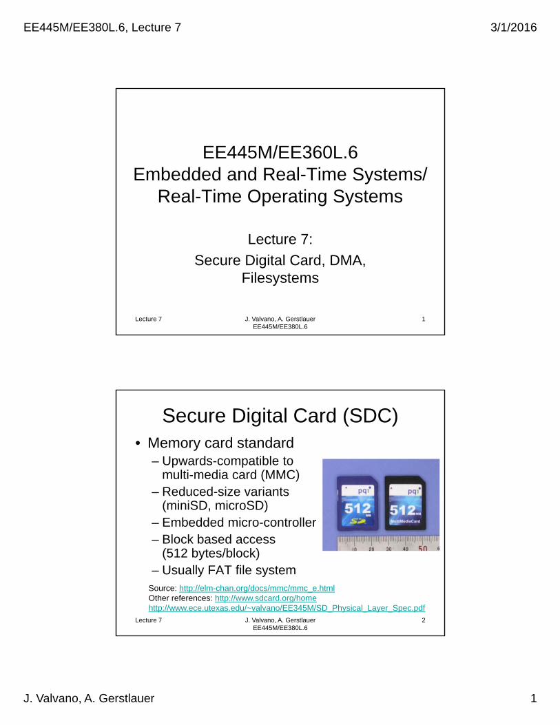
Secure Digital Card (SDC)• Memory card standard
– Upwards-compatible to multi-media card (MMC)
– Reduced-size variants (miniSD, microSD)
– Embedded micro-controller– Block based access
(512 bytes/block)– Usually FAT file system
Lecture 7 J. Valvano, A. Gerstlauer EE445M/EE380L.6
2
Source: http://elm-chan.org/docs/mmc/mmc_e.htmlOther references: http://www.sdcard.org/homehttp://www.ece.utexas.edu/~valvano/EE345M/SD_Physical_Layer_Spec.pdf
EE445M/EE380L.6, Lecture 7 3/1/2016
J. Valvano, A. Gerstlauer 2
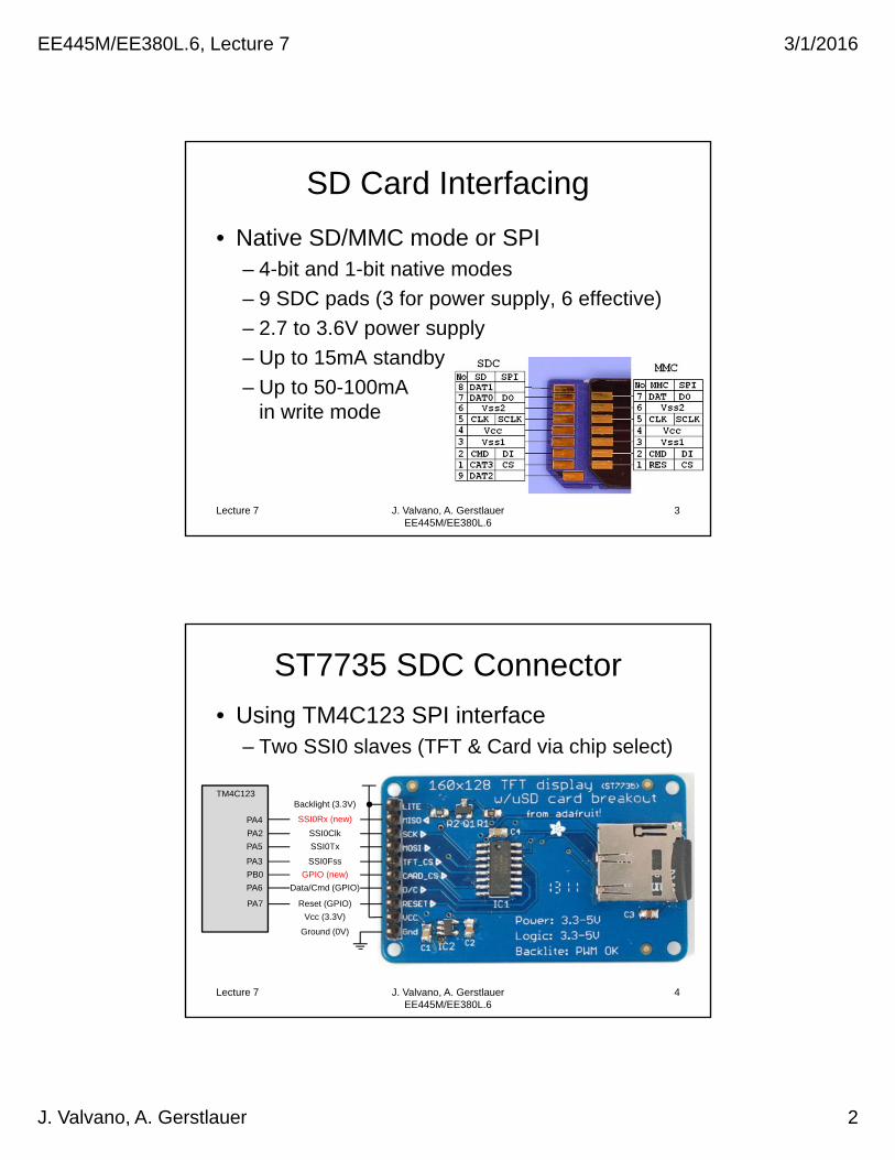
SD Card Interfacing
• Native SD/MMC mode or SPI– 4-bit and 1-bit native modes
– 9 SDC pads (3 for power supply, 6 effective)
– 2.7 to 3.6V power supply
– Up to 15mA standby
– Up to 50-100mAin write mode
Lecture 7 J. Valvano, A. Gerstlauer EE445M/EE380L.6
3
ST7735 SDC Connector
• Using TM4C123 SPI interface– Two SSI0 slaves (TFT & Card via chip select)
Lecture 7 J. Valvano, A. Gerstlauer EE445M/EE380L.6
4
Backlight (3.3V)
SSI0Rx (new)
SSI0Clk
SSI0Tx
SSI0Fss
GPIO (new)
Data/Cmd (GPIO)
Reset (GPIO)
Vcc (3.3V)
Ground (0V)
PA4
PA2
PA5
PA3
PB0
PA6
PA7
TM4C123
EE445M/EE380L.6, Lecture 7 3/1/2016
J. Valvano, A. Gerstlauer 3
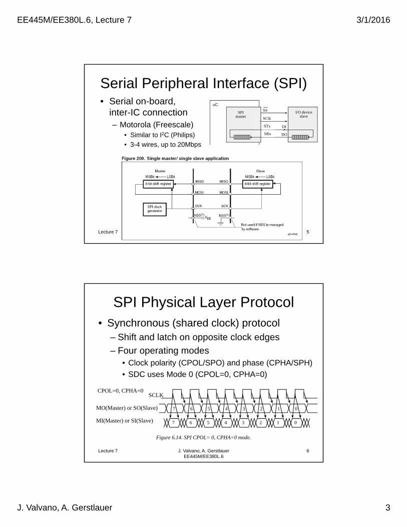
Serial Peripheral Interface (SPI)• Serial on-board,
inter-IC connection– Motorola (Freescale)
• Similar to I2C (Philips)
• 3-4 wires, up to 20Mbps
Lecture 7 J. Valvano, A. Gerstlauer EE445M/EE380L.6
5
SS
SClk
MOSI
MISO
SPImaster
I/O deviceslave
STM32
PA4
PA5
PA7
PA6
uC
DI
DO
STx
SRx
SPI Physical Layer Protocol• Synchronous (shared clock) protocol
– Shift and latch on opposite clock edges
– Four operating modes• Clock polarity (CPOL/SPO) and phase (CPHA/SPH)
• SDC uses Mode 0 (CPOL=0, CPHA=0)
Lecture 7 J. Valvano, A. Gerstlauer EE445M/EE380L.6
6
CPOL=0, CPHA=0SCLK
7 06 5 4 3 2 1
7 06 5 4 3 2 1MO(Master) or SO(Slave)
MI(Master) or SI(Slave)
Figure 6.14. SPI CPOL= 0, CPHA=0 mode.
EE445M/EE380L.6, Lecture 7 3/1/2016
J. Valvano, A. Gerstlauer 4
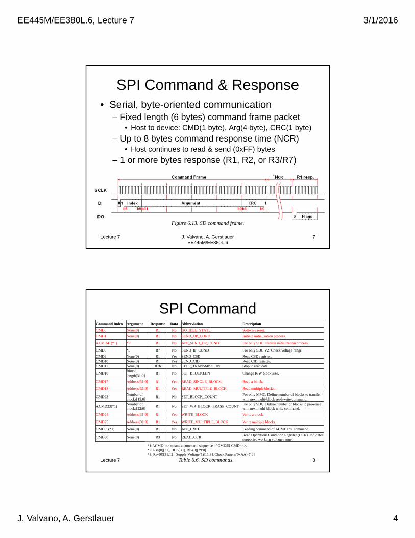
SPI Command & Response• Serial, byte-oriented communication
– Fixed length (6 bytes) command frame packet• Host to device: CMD(1 byte), Arg(4 byte), CRC(1 byte)
– Up to 8 bytes command response time (NCR)• Host continues to read & send (0xFF) bytes
– 1 or more bytes response (R1, R2, or R3/R7)
Lecture 7 J. Valvano, A. Gerstlauer EE445M/EE380L.6
7
Figure 6.13. SD command frame.
SPI CommandCommand Index Argument Response Data Abbreviation Description
CMD0 None(0) R1 No GO_IDLE_STATE Software reset.
CMD1 None(0) R1 No SEND_OP_COND Initiate initialization process.
ACMD41(*1) *2 R1 No APP_SEND_OP_COND For only SDC. Initiate initialization process.
CMD8 *3 R7 No SEND_IF_COND For only SDC V2. Check voltage range.
CMD9 None(0) R1 Yes SEND_CSD Read CSD register.CMD10 None(0) R1 Yes SEND_CID Read CID register.CMD12 None(0) R1b No STOP_TRANSMISSION Stop to read data.
CMD16Blocklength[31:0]
R1 No SET_BLOCKLEN Change R/W block size.
CMD17 Address[31:0] R1 Yes READ_SINGLE_BLOCK Read a block.
CMD18 Address[31:0] R1 Yes READ_MULTIPLE_BLOCK Read multiple blocks.
CMD23Number ofblocks[15:0]
R1 No SET_BLOCK_COUNTFor only MMC. Define number of blocks to transferwith next multi-block read/write command.
ACMD23(*1)Number ofblocks[22:0]
R1 No SET_WR_BLOCK_ERASE_COUNTFor only SDC. Define number of blocks to pre-erasewith next multi-block write command.
CMD24 Address[31:0] R1 Yes WRITE_BLOCK Write a block.
CMD25 Address[31:0] R1 Yes WRITE_MULTIPLE_BLOCK Write multiple blocks.
CMD55(*1) None(0) R1 No APP_CMD Leading command of ACMD<n> command.
CMD58 None(0) R3 No READ_OCRRead Operations Condition Register (OCR). Indicates supported working voltage range.
Lecture 7 J. Valvano, A. Gerstlauer EE445M/EE380L.6
8
*1:ACMD<n> means a command sequence of CMD55-CMD<n>.*2: Rsv(0)[31], HCS[30], Rsv(0)[29:0]*3: Rsv(0)[31:12], Supply Voltage(1)[11:8], Check Pattern(0xAA)[7:0]
Table 6.6. SD commands.

EE445M/EE380L.6, Lecture 7 3/1/2016
J. Valvano, A. Gerstlauer 5
SPI Response
Lecture 7 J. Valvano, A. Gerstlauer EE445M/EE380L.6
9
R1b Response:Variable length busy flag (DO held low)
SDC Initialization Procedure• To put SDC into SPI mode
1. Power ON (Insertion)• After Vcc > 2.2V, wait for > 1ms• Set clock between 100 and 400 kHz• Set DI and CS high, send 74 or more clock pulses
2. Software reset (Set to SPI mode)• Send CMD0 with CS low (and proper CRC)• Card enters SPI and responds with R1 idle state (0x01)
3. Initialization (CMD0, CMD1/ACMD41, CMD58)• Send ACMD41 (SDCv1) or CMD1 (MMC)• Repeat until R1 response changes to 0x00 (100s of ms)• Increase clock rate (25Mhz or more)
Lecture 7 J. Valvano, A. Gerstlauer EE445M/EE380L.6
10
EE445M/EE380L.6, Lecture 7 3/1/2016
J. Valvano, A. Gerstlauer 6
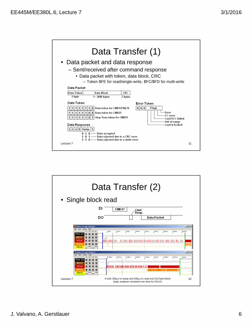
Data Transfer (1)
Lecture 7 J. Valvano, A. Gerstlauer EE445M/EE380L.6
11
• Data packet and data response– Sent/received after command response
• Data packet with token, data block, CRC– Token $FE for read/single-write, $FC/$FD for multi-write
Data Transfer (2)• Single block read
Lecture 7 J. Valvano, A. Gerstlauer EE445M/EE380L.6
12It took 300s to setup and 535s to read one 512 byte block (logic analyzer resolution too slow for SCLK)

EE445M/EE380L.6, Lecture 7 3/1/2016
J. Valvano, A. Gerstlauer 7
Data Transfer (3)• Single block write
Lecture 7 J. Valvano, A. Gerstlauer EE445M/EE380L.6
13It took 272s to write one 512 byte block
(logic analyzer resolution too slow for SCLK)
Data Transfer (4)
• Multi block read
• Multi block write
Lecture 7 J. Valvano, A. Gerstlauer EE445M/EE380L.6
14
EE445M/EE380L.6, Lecture 7 3/1/2016
J. Valvano, A. Gerstlauer 8
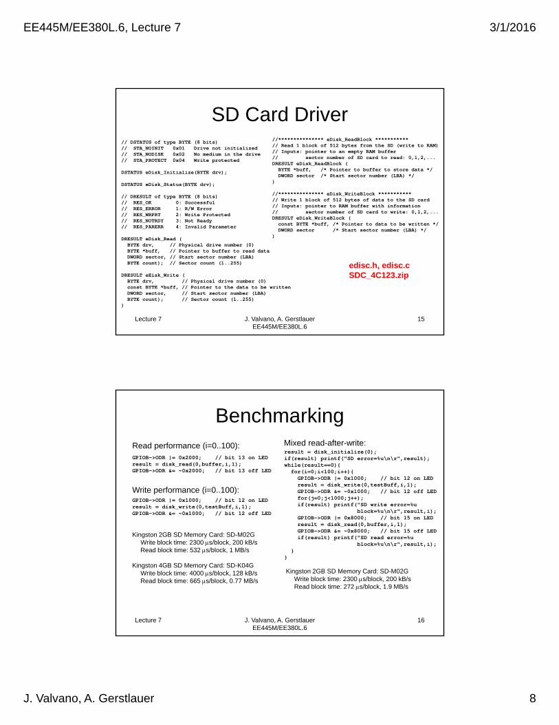
SD Card Driver
Lecture 7 J. Valvano, A. Gerstlauer EE445M/EE380L.6
15
// DSTATUS of type BYTE (8 bits)// STA_NOINIT 0x01 Drive not initialized// STA_NODISK 0x02 No medium in the drive// STA_PROTECT 0x04 Write protected
DSTATUS eDisk_Initialize(BYTE drv);
DSTATUS eDisk_Status(BYTE drv);
// DRESULT of type BYTE (8 bits)// RES_OK 0: Successful // RES_ERROR 1: R/W Error // RES_WRPRT 2: Write Protected // RES_NOTRDY 3: Not Ready // RES_PARERR 4: Invalid Parameter
DRESULT eDisk_Read (BYTE drv, // Physical drive number (0)BYTE *buff, // Pointer to buffer to read dataDWORD sector, // Start sector number (LBA)BYTE count); // Sector count (1..255)
DRESULT eEisk_Write (BYTE drv, // Physical drive number (0)const BYTE *buff, // Pointer to the data to be writtenDWORD sector, // Start sector number (LBA)BYTE count); // Sector count (1..255)
)
//*************** eDisk_ReadBlock ***********// Read 1 block of 512 bytes from the SD (write to RAM)// Inputs: pointer to an empty RAM buffer// sector number of SD card to read: 0,1,2,...DRESULT eDisk_ReadBlock (BYTE *buff, /* Pointer to buffer to store data */DWORD sector /* Start sector number (LBA) */
)
//*************** eDisk_WriteBlock ***********// Write 1 block of 512 bytes of data to the SD card// Inputs: pointer to RAM buffer with information// sector number of SD card to write: 0,1,2,...DRESULT eDisk_WriteBlock (const BYTE *buff, /* Pointer to data to be written */DWORD sector /* Start sector number (LBA) */
)
edisc.h, edisc.cSDC_4C123.zip
Benchmarking
Lecture 7 J. Valvano, A. Gerstlauer EE445M/EE380L.6
16
GPIOB->ODR |= 0x1000; // bit 12 on LEDresult = disk_write(0,testBuff,i,1);GPIOB->ODR &= ~0x1000; // bit 12 off LED
GPIOB->ODR |= 0x2000; // bit 13 on LEDresult = disk_read(0,buffer,i,1);GPIOB->ODR &= ~0x2000; // bit 13 off LED
Kingston 2GB SD Memory Card: SD-M02GWrite block time: 2300 s/block, 200 kB/sRead block time: 532 s/block, 1 MB/s
Kingston 4GB SD Memory Card: SD-K04GWrite block time: 4000 s/block, 128 kB/sRead block time: 665 s/block, 0.77 MB/s
result = disk_initialize(0);if(result) printf("SD error=%u\n\r",result);while(result==0){
for(i=0;i<100;i++){GPIOB->ODR |= 0x1000; // bit 12 on LED result = disk_write(0,testBuff,i,1);GPIOB->ODR &= ~0x1000; // bit 12 off LED for(j=0;j<1000;j++);if(result) printf("SD write error=%u
block=%u\n\r",result,i);GPIOB->ODR |= 0x8000; // bit 15 on LED result = disk_read(0,buffer,i,1);GPIOB->ODR &= ~0x8000; // bit 15 off LED if(result) printf("SD read error=%u
block=%u\n\r",result,i);}
}
Read performance (i=0..100):
Write performance (i=0..100):
Mixed read-after-write:
Kingston 2GB SD Memory Card: SD-M02GWrite block time: 2300 s/block, 200 kB/sRead block time: 272 s/block, 1.9 MB/s
EE445M/EE380L.6, Lecture 7 3/1/2016
J. Valvano, A. Gerstlauer 9
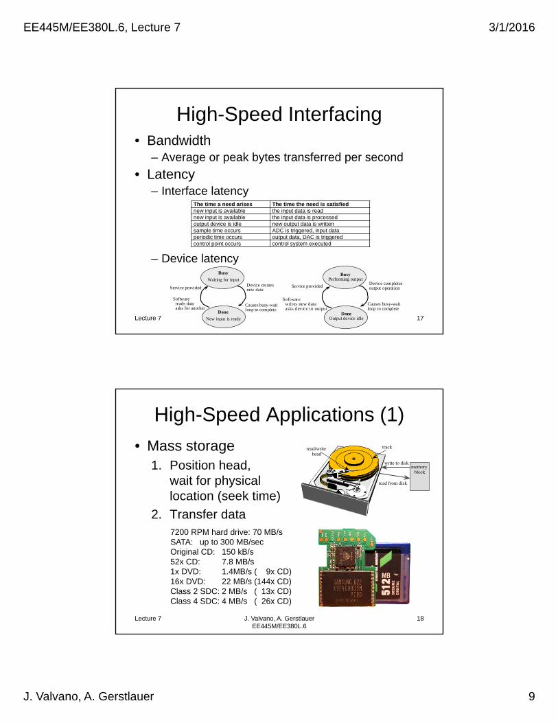
High-Speed Interfacing• Bandwidth
– Average or peak bytes transferred per second
• Latency– Interface latency
– Device latency
Lecture 7 J. Valvano, A. Gerstlauer EE445M/EE380L.6
17
The time a need arises The time the need is satisfiednew input is available the input data is readnew input is available the input data is processedoutput device is idle new output data is writtensample time occurs ADC is triggered, input dataperiodic time occurs output data, DAC is triggeredcontrol point occurs control system executed
New input is ready
Waiting for inputDevice createsnew data
Software reads data asks for another
Busy
Done
Causes busy-waitloop to complete
Service provided
DoneOutput device idle
BusyPerforming output
Device completesoutput operation
Software writes new data asks device to output
Causes busy-waitloop to complete
Service provided
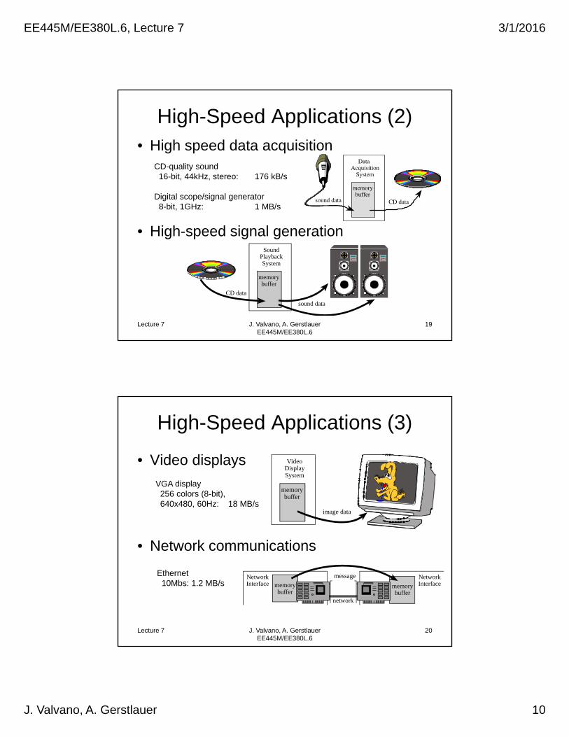
High-Speed Applications (1)
• Mass storage1. Position head,
wait for physicallocation (seek time)
2. Transfer data
Lecture 7 J. Valvano, A. Gerstlauer EE445M/EE380L.6
18
read/write head
track
read from disk
write to diskmemory
block
7200 RPM hard drive: 70 MB/sSATA: up to 300 MB/secOriginal CD: 150 kB/s52x CD: 7.8 MB/s1x DVD: 1.4MB/s ( 9x CD) 16x DVD: 22 MB/s (144x CD)Class 2 SDC: 2 MB/s ( 13x CD)Class 4 SDC: 4 MB/s ( 26x CD)
EE445M/EE380L.6, Lecture 7 3/1/2016
J. Valvano, A. Gerstlauer 10
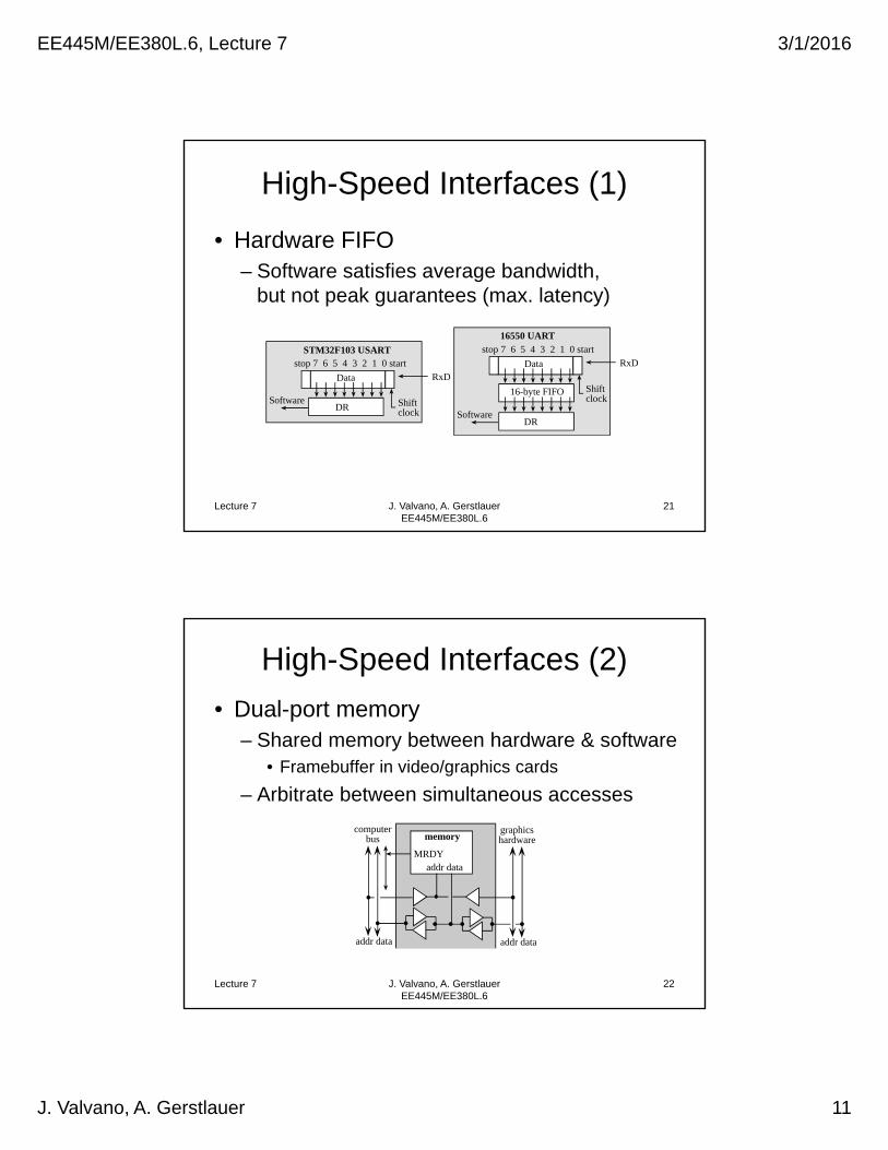
High-Speed Applications (2)• High speed data acquisition
• High-speed signal generation
Lecture 7 J. Valvano, A. Gerstlauer EE445M/EE380L.6
19
memory buffer
Data Acquisition
System
sound data CD data
memorybuffer
SoundPlaybackSystem
sound data
CD data
CD-quality sound16-bit, 44kHz, stereo: 176 kB/s
Digital scope/signal generator8-bit, 1GHz: 1 MB/s
High-Speed Applications (3)
• Video displays
• Network communications
Lecture 7 J. Valvano, A. Gerstlauer EE445M/EE380L.6
20
memorybuffer
VideoDisplaySystem
image data
VGA display256 colors (8-bit), 640x480, 60Hz: 18 MB/s
network
message
memorybuffer
NetworkInterface memory
buffer
NetworkInterface
Ethernet10Mbs: 1.2 MB/s
EE445M/EE380L.6, Lecture 7 3/1/2016
J. Valvano, A. Gerstlauer 11
High-Speed Interfaces (1)
• Hardware FIFO– Software satisfies average bandwidth,
but not peak guarantees (max. latency)
Lecture 7 J. Valvano, A. Gerstlauer EE445M/EE380L.6
21
STM32F103 USARTstop 7 6 5 4 3 2 1 0 start
DR
RxD
Software
Data
Shiftclock
16550 UARTstop 7 6 5 4 3 2 1 0 start
16-byte FIFO
RxD
Software
Data
Shiftclock
DR
High-Speed Interfaces (2)
• Dual-port memory– Shared memory between hardware & software
• Framebuffer in video/graphics cards
– Arbitrate between simultaneous accesses
Lecture 7 J. Valvano, A. Gerstlauer EE445M/EE380L.6
22
memory
addr data
computerbus
addr data
graphicshardware
addr data
MRDY
EE445M/EE380L.6, Lecture 7 3/1/2016
J. Valvano, A. Gerstlauer 12
High-Speed Interfaces (3)
• Bank-switched memory– Double-buffering
• Share memory, but avoid conflicts
– Alternate between different banks or buffers
• Hardware accesses bank A/B
• Software accesses bank B/A
• Switch banks (M=0/1)
Lecture 7 J. Valvano, A. Gerstlauer EE445M/EE380L.6
23
memory bank Aaddr data
computer bus
addr data
I/O hardware
addr data
M
memory bank B
addr data
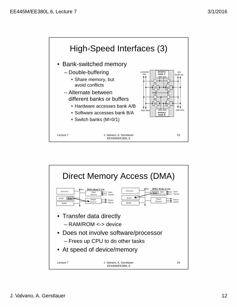
Direct Memory Access (DMA)
• Transfer data directly – RAM/ROM <-> device
• Does not involve software/processor – Frees up CPU to do other tasks
• At speed of device/memory
Lecture 7 J. Valvano, A. Gerstlauer EE445M/EE380L.6
24
processor
RAM
ROM
Input Devices
Input Signals
Output Devices
Output Signals
Bus
data
DMA Read Cycledata
processor
RAM
ROM
Input Devices
Input Signals
Output Devices
Output Signals
Bus DMA Write Cycle
EE445M/EE380L.6, Lecture 7 3/1/2016
J. Valvano, A. Gerstlauer 13
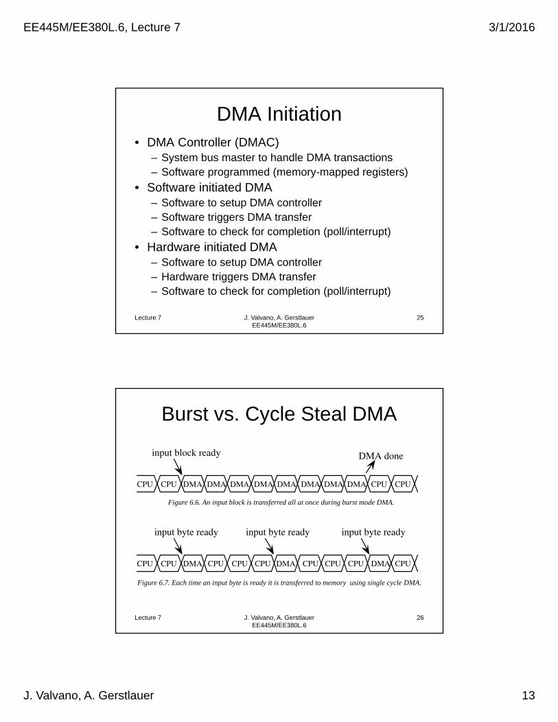
DMA Initiation• DMA Controller (DMAC)
– System bus master to handle DMA transactions– Software programmed (memory-mapped registers)
• Software initiated DMA– Software to setup DMA controller– Software triggers DMA transfer– Software to check for completion (poll/interrupt)
• Hardware initiated DMA– Software to setup DMA controller– Hardware triggers DMA transfer– Software to check for completion (poll/interrupt)
Lecture 7 J. Valvano, A. Gerstlauer EE445M/EE380L.6
25
Burst vs. Cycle Steal DMA
Lecture 7 J. Valvano, A. Gerstlauer EE445M/EE380L.6
26
input byte ready
CPU CPU DMA DMA DMACPU CPUCPU CPU CPU CPU CPU
input byte ready input byte ready
Figure 6.7. Each time an input byte is ready it is transferred to memory using single cycle DMA.
input block ready
CPU CPU DMA DMA DMA DMA DMA DMA DMA DMA CPU CPU
DMA done
Figure 6.6. An input block is transferred all at once during burst mode DMA.
EE445M/EE380L.6, Lecture 7 3/1/2016
J. Valvano, A. Gerstlauer 14
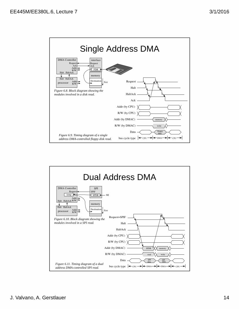
Single Address DMA
Lecture 7 J. Valvano, A. Gerstlauer EE445M/EE380L.6
27
memory
SizeDestination
DMA Controller interface
FDR
Request Request
Addr R/W
Halt HaltAck
processor
Halt HaltAckAddr R/W
AckAck
Request
Halt
HaltAck
Ack
Addr (by CPU)
R/W (by CPU)
Addr (by DMAC)
R/W (by DMAC)
Data
bus cycle type
floppydata
memory
write
CPU DMA CPU
Figure 6.8. Block diagram showing the modules involved in a disk read.
Figure 6.9. Timing diagram of a single address DMA-controlled floppy disk read.
Dual Address DMA
Lecture 7 J. Valvano, A. Gerstlauer EE445M/EE380L.6
28
Request=SPIF
Halt
HaltAck
Addr (by CPU)
R/W (by CPU)
Addr (by DMAC)
R/W (by DMAC)
Data
bus cycle type
SPIdata
SPDR
read
CPU DMA CPU
SPIdata
memory
write
DMA
Figure 6.10. Block diagram showing the modules involved in a SPI read.
Figure 6.11. Timing diagram of a dual address DMA-controlled SPI read.
memory
SizeDestination
DMA Controller SPI
SPDR
SPIF Request
Addr R/WHalt HaltAck
processor
Halt HaltAckAddr R/W
MItemp

EE445M/EE380L.6, Lecture 7 3/1/2016
J. Valvano, A. Gerstlauer 15
TM4C123 DMA Programming
Lecture 7 J. Valvano, A. Gerstlauer EE445M/EE380L.6
29
DMA Channels
Lecture 7 J. Valvano, A. Gerstlauer EE445M/EE380L.6
30
(DMACHMAPn, High/Low Priority via DMAPRIOSET/DMAPRIOCLR)
EE445M/EE380L.6, Lecture 7 3/1/2016
J. Valvano, A. Gerstlauer 16
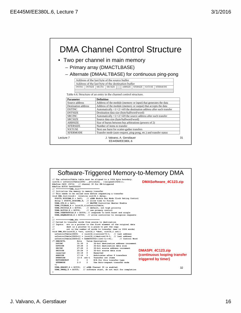
DMA Channel Control Structure• Two per channel in main memory
– Primary array (DMACTLBASE)
– Alternate (DMAALTBASE) for continuous ping-pong
Lecture 7 J. Valvano, A. Gerstlauer EE445M/EE380L.6
31
Address of the last byte of the source buffer Address of the last byte of the destination buffer DSTINC DSTSIZE SRCINC SRCSIZE ARBSIZE XFERSIZE NXTUSE XFERMODE
Table 6.4. Structure of an entry in the channel control structure.
Parameter DefinitionSource address Address of the module (memory or input) that generates the dataDestination address Address of the module (memory or output) that accepts the dataDSTINC Automatically +1/+2/+4/0 the destination address after each transferDSTSIZE Destination data size (byte/halfword/word)SRCINC Automatically +1/+2/+4/0 the source address after each transferSRCSIZE Source data size (byte/halfword/word)ARBSIZE Size of bursts between bus arbitrations (powers of 2)XFERSIZE Number of items to transferNXTUSE Next use burst for scatter-gather transfersXFERMODE Transfer mode (auto-request, ping-pong, etc.) and transfer status
Lecture 7 J. Valvano, A. Gerstlauer EE445M/EE380L.6
32
// The ucControlTable table must be aligned to a 1024 byte boundary.uint32_t ucControlTable[256] __attribute__ ((aligned(1024)));#define CH30 (30*4) // channel 30 for SW-triggered#define BIT30 0x40000000// ************DMA_Init*****************// Initialize the memory to memory transfer// This needs to be called once before requesting a transfervoid DMA_Init(void){ volatile uint32_t delay;
SYSCTL_RCGCDMA_R = 0x01; // µDMA Module Run Mode Clock Gating Controldelay = SYSCTL_RCGCDMA_R; // allow time to finish UDMA_CFG_R = 0x01; // MASTEN Controller Master EnableUDMA_CTLBASE_R = (uint32_t)ucControlTable;UDMA_PRIOCLR_R = BIT30; // default, not high priorityUDMA_ALTCLR_R = BIT30; // use primary controlUDMA_USEBURSTCLR_R = BIT30; // responds to both burst and single UDMA_REQMASKCLR_R = BIT30; // allow controller to recognize requests
}// ************DMA_Xfr *****************// Called to transfer words from source to destination// Inputs: src is a pointer to the first element of the original data// dest is a pointer to a place to put the copy// cnt is the number of words to transfer (max is 1024 words)void DMA_Xfr(uint32_t *src, uint32_t *dest, uint32_t cnt){
ucControlTable[CH30] = (uint32_t)src+cnt*4-1; // last addressucControlTable[CH30+1] = (uint32_t)dest+cnt*4-1; // last addressucControlTable[CH30+2] = 0xAA00C002+((cnt-1)<<4); // Control Word
/* DMACHCTL Bits Value DescriptionDSTINC 31:30 2 32-bit destination address incrementDSTSIZE 29:28 2 32-bit destination data sizeSRCINC 27:26 2 32-bit source address incrementSRCSIZE 25:24 2 32-bit source data sizereserved 23:18 0 Reserved ARBSIZE 17:14 3 Arbitrates after 8 transfersXFERSIZE 13:4 cnt-1 Transfer cnt itemsNXTUSEBURST 3 0 N/A for this transfer typeXFERMODE 2:0 2 Use Auto-request transfer mode
*/UDMA_ENASET_R = BIT30; // µDMA Channel 30 is enabled.UDMA_SWREQ_R = BIT30; // software start, do not wait for completion
}
DMASoftware_4C123.zip
DMASPI_4C123.zip(continuous looping transfertriggered by timer)
Software-Triggered Memory-to-Memory DMA
EE445M/EE380L.6, Lecture 7 3/1/2016
J. Valvano, A. Gerstlauer 17
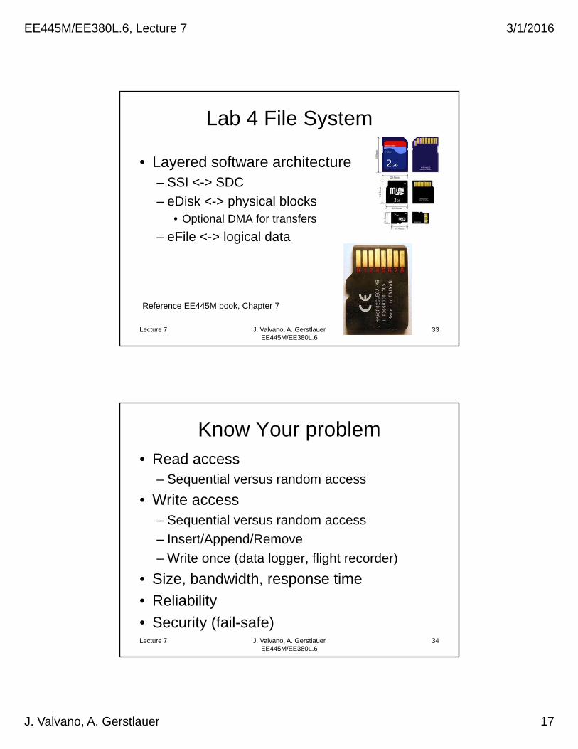
Lab 4 File System
• Layered software architecture– SSI <-> SDC
– eDisk <-> physical blocks• Optional DMA for transfers
– eFile <-> logical data
Lecture 7 J. Valvano, A. Gerstlauer EE445M/EE380L.6
Reference EE445M book, Chapter 7
33
Lecture 7 J. Valvano, A. Gerstlauer EE445M/EE380L.6
Know Your problem• Read access
– Sequential versus random access
• Write access– Sequential versus random access
– Insert/Append/Remove
– Write once (data logger, flight recorder)
• Size, bandwidth, response time
• Reliability
• Security (fail-safe)34

EE445M/EE380L.6, Lecture 7 3/1/2016
J. Valvano, A. Gerstlauer 18
Lecture 7 J. Valvano, A. Gerstlauer EE445M/EE380L.6
Know your disk
• Block size
• Disk size
• Read/write speed
• Types and chances of error– Wear leveling
– Conditional probability
35
Lecture 7 J. Valvano, A. Gerstlauer EE445M/EE380L.6
File System Responsibilities
• Logical to physical translation– Byte number to block number
• Directory– File name to physical translation
• Free space– Used
– Free
– Damaged
36

EE445M/EE380L.6, Lecture 7 3/1/2016
J. Valvano, A. Gerstlauer 19
Lecture 7 J. Valvano, A. Gerstlauer EE445M/EE380L.6
File System Performance• File size
• Disk size
• Number of files
• Speed– Time to create, open, close
– Write bandwidth
– Read bandwidth
• Fragmentation– External if max file size < total free space
37
Lecture 7 J. Valvano, A. Gerstlauer EE445M/EE380L.6
File System Allocation (1)
• Contiguous allocation– First fit
– Best fit
– Worst fit A,11,3
B,3,7
C,22,5
Directory
0123456789
10111213141516171819202122232425262728293031
File B
File A
File C
NameStart blockSize or length
Size could be in bytes or blocks
Good for sequential write, never eraseFast random read access
Internal fragmentation: on average, each file wastes 1/2 blockExternal fragmentation: largest file size to allocate < free space
38

EE445M/EE380L.6, Lecture 7 3/1/2016
J. Valvano, A. Gerstlauer 20
Lecture 7 J. Valvano, A. Gerstlauer EE445M/EE380L.6
File System Allocation (2)
• Linked allocation
Each block has a link and a sizeGood for erase, append, deleteSlow for random accessInternal fragmentation: on average, each file wastes 1/2 blockNo external fragmentation
2 3 4 5 6 70 1
10 11 12 13 14 158 9
18 19 20 21 22 2316 17
26 27 28 29 30 3124 25
A,10
B,2
C,20
Directory
NameStart block
39
Lecture 7 J. Valvano, A. Gerstlauer EE445M/EE380L.6
Free Space Management
• Linked allocation of free space
What if bad block?
2 3 4 5 6 70 1
10 11 12 13 14 158 9
18 19 20 21 22 2316 17
26 27 28 29 30 3124 25
A,10
B,2
C,20
Directory
NameStart block
*,1
To handle wear-levelingfree to one end of listallocate from other end
40

EE445M/EE380L.6, Lecture 7 3/1/2016
J. Valvano, A. Gerstlauer 21
Lecture 7 J. Valvano, A. Gerstlauer EE445M/EE380L.6
File System Allocation (3)
• Indexed allocation
Good for erase, append, deleteFast for random accessNo external fragmentation
A,0,3
B,3,7
C,10,5
Directory
0123456789
10111213141516171819202122232425262728293031
NameStart indexSize or length
0123456789
10111213141516171819202122232425262728293031
File B
File A
File C
103
122
11191314
76
2028272618
-----------------
Index table Disk
Reliable? Two level index table?
41
‘tree’
‘jv1’
Block2
1
508
Data
Directory in Block 0 Block1
0
11
Data
Free
Block3
0
20
Data
Free
Block4
5
508
Data
Block6
4
508
Data
Block5
0
24
Data
Free
2519
320
‘Jon’61040
‘tree’‘jv1’
‘jv1’ ‘Jon’
‘Jon’
‘Jon’
Directory
• Name, Type, Date, Size, How to access
How many files?
2 bytes for link to next block2 bytes for size
Internal fragmentation
Disk smaller than 32Meb
42Lecture 7 J. Valvano, A. Gerstlauer EE445M/EE380L.6
EE445M/EE380L.6, Lecture 7 3/1/2016
J. Valvano, A. Gerstlauer 22
Lecture 7 J. Valvano, A. Gerstlauer EE445M/EE380L.6
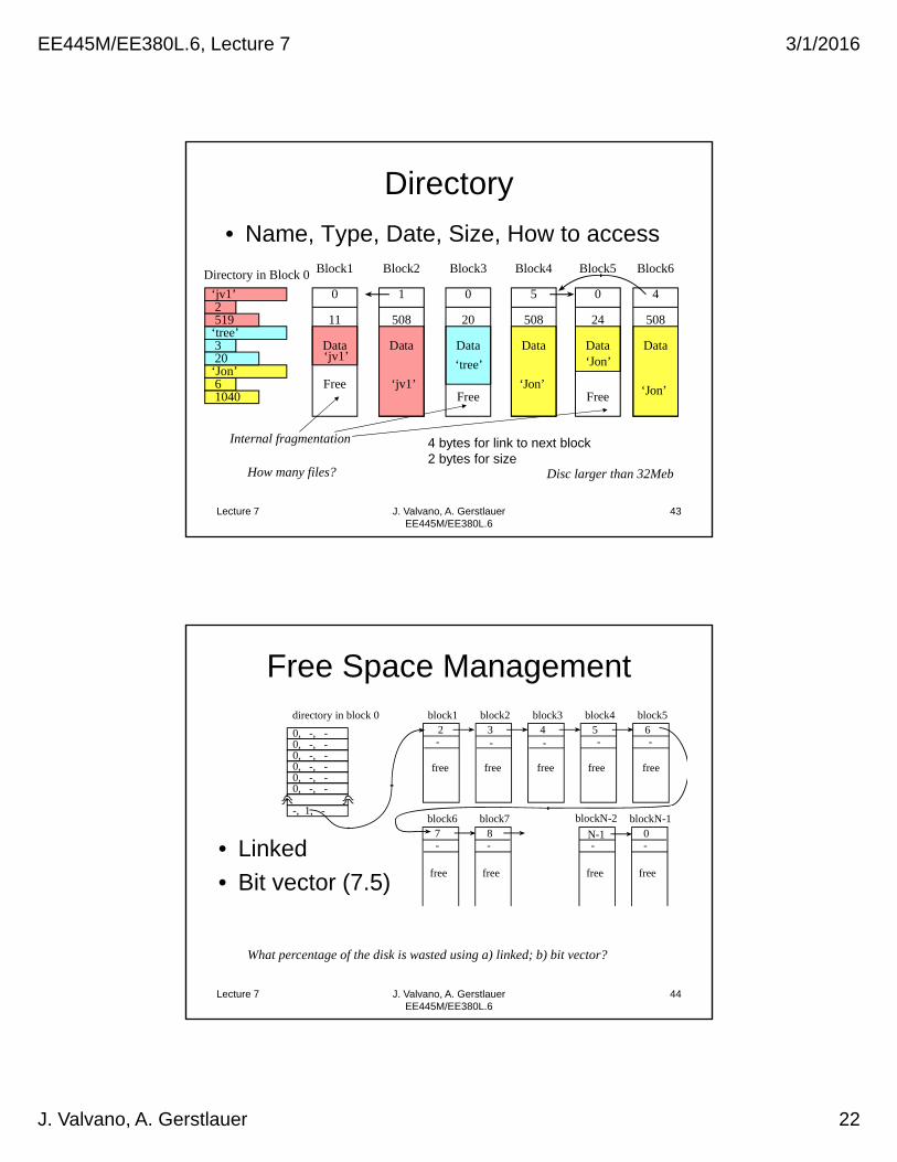
Directory
• Name, Type, Date, Size, How to access
How many files?
4 bytes for link to next block2 bytes for size
Internal fragmentation
Disc larger than 32Meb
43
‘tree’
‘jv1’
Block2
1
508
Data
Directory in Block 0 Block1
0
11
Data
Free
Block3
0
20
Data
Free
Block4
5
508
Data
Block6
4
508
Data
Block5
0
24
Data
Free
2519
320
‘Jon’61040
‘tree’‘jv1’
‘jv1’ ‘Jon’
‘Jon’
‘Jon’
Lecture 7 J. Valvano, A. Gerstlauer EE445M/EE380L.6
Free Space Management
• Linked
• Bit vector (7.5)
What percentage of the disk is wasted using a) linked; b) bit vector?
directory in block 0
blockN-10-
free
block67-
free
block78-
free
blockN-2
N-1-
free
block12-
free
block23-
block34-
block45-
free
block56-
free
0, -, -0, -, -0, -, -0, -, -0, -, -0, -, -
-, 1, -
free free
44

EE445M/EE380L.6, Lecture 7 3/1/2016
J. Valvano, A. Gerstlauer 23
Lecture 7 J. Valvano, A. Gerstlauer EE445M/EE380L.6
File Allocation Table (FAT)
Derive a relation between FAT size and disk size
A,10
B,2
C,20
Directory
0123456789
10111213141516171819202122232425262728293031
NameStart block
0123456789
10111213141516171819202122232425262728293031
File B
File A
File C
xx
1112
--06--3
190
147---0
1328
-----
182627
---
File Allocation Table Disk
What if bad block? 45
Lecture 7 J. Valvano, A. Gerstlauer EE445M/EE380L.6
File Allocation Table (FAT)
External fragmentation?Internal fragmentation?
Why cluster?
A,10
B,2
C,20
Directory
0123456789
10111213141516171819202122232425262728293031
NameStart block
0123456789
10111213141516171819202122232425262728293031
File B
File A
File C
xx
111258069
153
190
147
1617210
1328222324252918262730310
File Allocation Table Disk
*,4 Free space
46
EE445M/EE380L.6, Lecture 7 3/1/2016
J. Valvano, A. Gerstlauer 24
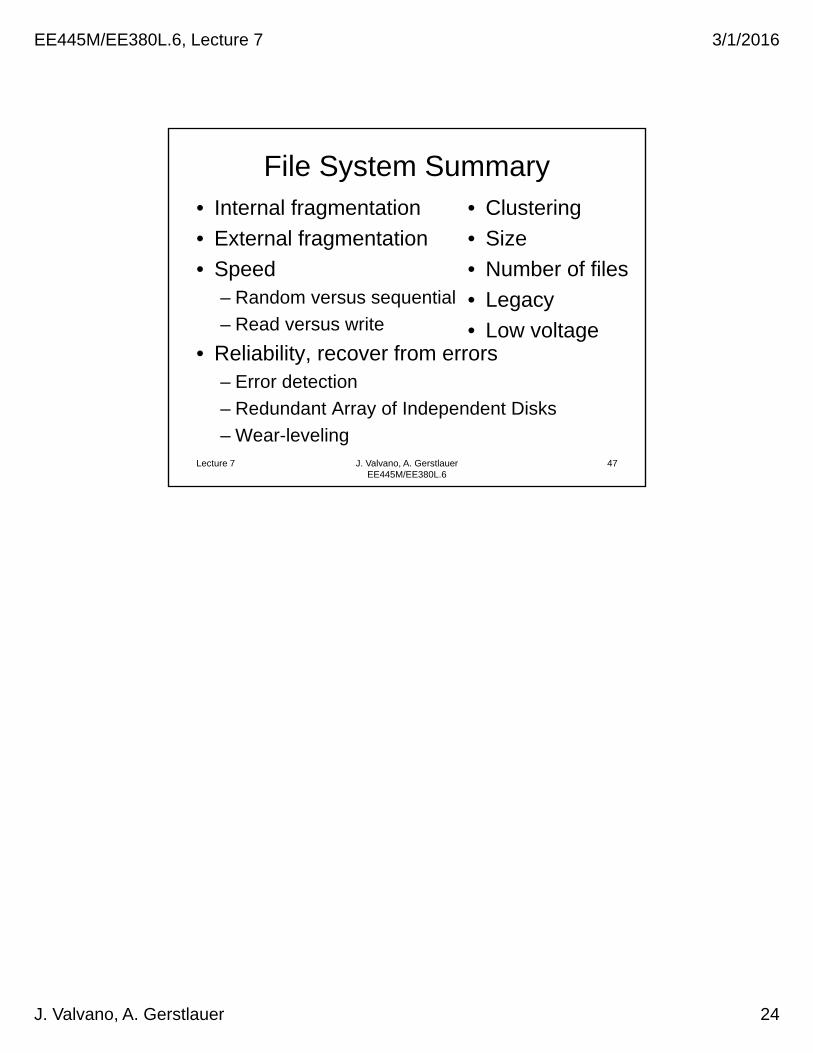
File System Summary• Internal fragmentation
• External fragmentation
• Speed– Random versus sequential
– Read versus write
• Reliability, recover from errors– Error detection
– Redundant Array of Independent Disks
– Wear-levelingLecture 7 J. Valvano, A. Gerstlauer
EE445M/EE380L.6
• Clustering
• Size
• Number of files
• Legacy
• Low voltage
47