Sectional drawing · 554 Angle Seat Globe Valve, Metal Construction The GEMÜ 554 pneumatically...
14
554 Angle Seat Globe Valve, Metal Construction The GEMÜ 554 pneumatically operated 2/2-way valve has a plastic pneumatic piston actuator. The valve spindle is sealed by a self-adjusting gland packing or a compact seal cartridge, dependent on the size and ver- sion. A wiper ring or the wiper contour of the seal cartridge additionally pro- tects the valve spindle against contamination and damage thus providing low maintenance and reliable valve spindle sealing even after a long service life. Features • Suitable for inert and corrosive* liquid and gaseous media • Substantially reduced installation dimensions when using the body with male threads which can be installed using union nuts • Materials of all medium wetted parts can be selected to suit relevant applications • Control valves with control cone available (see data sheet GEMÜ 554 control valve) • Versions according to ATEX on request Advantages • Various types of valve body connections: Threaded sockets, threaded spigots, butt weld spigots • Good flow capability • Extensive range of accessories • Low weight • Optionally suitable for contact with food according to Regulation (EC) No. 1935/2004 (K-No. 2013) • Standard gland packing suitable for vacuum up to 20 mbar (abs.) *See information on working medium on page 2 Sectional drawing
Transcript of Sectional drawing · 554 Angle Seat Globe Valve, Metal Construction The GEMÜ 554 pneumatically...

554
Angle Seat Globe Valve,Metal
Construction The GEMÜ 554 pneumatically operated 2/2-way valve has a plastic pneumatic piston actuator. The valve spindle is sealed by a self-adjusting gland packing or a compact seal cartridge, dependent on the size and ver-sion. A wiper ring or the wiper contour of the seal cartridge additionally pro-tects the valve spindle against contamination and damage thus providing low maintenance and reliable valve spindle sealing even after a long service life.
Features• Suitable for inert and corrosive* liquid and gaseous media• Substantially reduced installation dimensions when using the body with
male threads which can be installed using union nuts• Materials of all medium wetted parts can be selected to suit relevant
applications• Control valves with control cone available
(see data sheet GEMÜ 554 control valve)• Versions according to ATEX on request
Advantages• Various types of valve body connections:
Threaded sockets, threaded spigots, butt weld spigots• Good flow capability• Extensive range of accessories• Low weight• Optionally suitable for contact with food according to Regulation (EC)
No. 1935/2004 (K-No. 2013)• Standard gland packing suitable for vacuum up to 20 mbar (abs.)
*See information on working medium on page 2
Sectional drawing

5542
Technical data
Technical data / ActuatorActuator
sizeFilling
volumePiston
diameterB 0.01 dm³ 30 mm
0, 3 0.05 dm³ 50 mm1, 4 0.125 dm³ 70 mm
2 0.625 dm³ 120 mm
Control pressure [bar]Normally closed (NC)
Actuator sizeB 4 - 80 4.8 - 7.01 5.5 - 7.0
2 4 - 7 (DN 20 - 40)5 - 7 (DN 50 - 80)
3, 4 min. control pressure see diagram /max. control pressure 7 bar
Normally open (NO) / Double acting (DA)
0, 1, 2 max. 7 bar(for values see diagram)
Control mediumInert gasesMax. perm. temperature of control medium: 60 °C
Ambient conditionsMax. ambient temperature 60 °C
Working mediumCorrosive, inert, gaseous and liquid media which have no negative impact on the physical and chemical properties of the body and seal materials.Max. perm. pressure of working medium see tableMedium temperatureActuator B, Seat seal NBR code 2 -10 to 80 °CActuator B, Seat seal PFA code 30 -10 to 160 °CActuator 0 - 4 -10 to 180 °CMax. permissible viscosity 600 mm²/s (cSt)Other versions for higher viscosities on request
Kv values [m³/h]DN 6 DN 8 DN 10 DN 15 DN 20 DN 25 DN 32 DN 40 DN 50 DN 65 DN 80
Butt weld spigots,DIN 11850 1.6 1.8 2.4 2.4 - - - - - - -
Butt weld spigots,DIN 11866 - 2.2 4.5 5.5 11.7 20.5 33.0 51.0 61.0 110.0 117.0
Threaded sockets,DIN ISO 228 - - 4.5 5.4 10.0 15.2 23.0 41.0 68.0 95.0 130.0
Kv values determined acc. to DIN EN 60534. The Kv value data refers to control function 1 (NC) and the largest actuator for each nominal size. The Kv values for other product configurations (e.g. other connections or body materials) may differ.
Max. operating pressure [bar]Actuator
size DN 6 DN 8 DN 10 DN 15 DN 20 DN 25 DN 32 DN 40 DN 50 DN 65 DN 80
Normally closed (NC) / Flow direction: under the seatB 10.0 10.0 10.0 10.0 - - - - - - -0 - - 12.0 12.0 6.0 2.5 - - - - -1 - - 25.0 25.0 20.0 10.0 7.0 4.5 3.0 - -2 - - - - 25.0 25.0 20.0 12.0 10.0 7.0 5.0
Normally closed (NC) / Flow direction: over the seat3 - - 10.0 10.0 10.0 10.0 8.0 6.0 4.0 - -4 - - 10.0 10.0 10.0 10.0 10.0 10.0 10.0 - -
Normally open (NO) / Double acting (DA) / Flow direction: under the seat0 - - 25.0 25.0 20.0 12.0 - - - - -1 - - 25.0 25.0 25.0 25.0 20.0 12.0 8.0 - -2 - - - - 25.0 25.0 25.0 25.0 25.0 18.0 10.0
For max. operating pressures the pressure/temperature correlation must be observed (see table on page 3).All pressures are gauge pressures.
Maximum permissible seat leakage rateSeat seal Standard Test procedure Leakage rate Test medium
PTFE, PFA, NBR DIN EN 12266-1 P12 A air

5543
0
1
5 10 15 20 25
2
3
4
5
6
7DN 20DN 25
DN 15
Steu
erdr
uck
[bar
]
Betriebsdruck [bar]0
1
5 10 15 20 25
2
3
4
5
6
7DN 40
DN 15DN 10
DN 20
DN 25
DN 32DN 50
Betriebsdruck [bar]
Steu
erdr
uck
[bar
]
0
1
5 10 15 20 25
2
3
4
5
6
7
DN 40
DN 65
DN 20DN 25DN 32
DN 50
DN 80
Steu
erdr
uck
[bar
]
Betriebsdruck [bar]
0
1
2 4 6 8 10
2
3
4
5
6
7
DN 25
DN 50
DN 20
Betriebsdruck [bar]
Steu
erdr
uck
[bar
]
DN 32
DN 15
DN 40
DN 10
0
1
2 4 6 8 10
2
3
4
5
6
7
DN 20DN 25
DN 15(DN 10)
Steu
erdr
uck
[bar
]
Betriebsdruck [bar]
DN 32DN 40DN 50
Operating pressure/Control pressure characteristics
Actuator size 1 Normally open (NO) Double acting (DA)
Min. control pressure dependent on operating pressure
(Flow direction: under the seat)
Actuator size 2 Normally open (NO) Double acting (DA)
Min. control pressure dependent on operating pressure
(Flow direction: under the seat)
Actuator size 3 Normally closed (NC)
Min. control pressure dependent on operating pressure
(Flow direction: over the seat)
Actuator size 4 Normally closed (NC)
Min. control pressure dependent on operating pressure
(Flow direction: over the seat)
Actuator size 0 Normally open (NO) Double acting (DA)
Min. control pressure dependent on operating pressure
(Flow direction: under the seat)
Con
trol p
ress
ure
[bar
]
Con
trol p
ress
ure
[bar
]
Con
trol p
ress
ure
[bar
]
Con
trol p
ress
ure
[bar
]
Con
trol p
ress
ure
[bar
]
Operating pressure [bar] Operating pressure [bar] Operating pressure [bar]
Operating pressure [bar] Operating pressure [bar]
Pressure / temperature correlation for angle seat globe valve bodies
Connection code Materialcode
Max. allowable operating pressures in bar at temperature °C*RT 100 150 200 250 300
1, 3C, 3D, 9 (up to DN 50) 9 16.0 16.0 16.0 13.5 - -1, 9 (from DN 65) 9 10.0 10.0 10.0 8.5 - -
1, 9, 17, 37, 60, 63, 3C, 3D 37 25.0 23,8 21,4 18,9 17,5 16,10, 16, 17, 18, 37, 59, 60, 65 34 25.0 24,5 22,4 20,3 18,2 16,1
13 (DN 15 - DN 50) 34 25.0 23.6 21.5 19.8 18.6 17.280, 88 (DN 15 - DN 40) 34 25.0 21.2 19.3** - - -80, 88 (DN 50 - DN 80) 34 16.0 16.0 16.0** - - -
82 (DN 15 - DN 32) 34 25.0 21.2 19.3** - - -82 (DN 40 - DN 65) 34 16.0 16.0 16.0** - - -86 (DN 15 - DN 40) 34 25.0 21.2 19.3** - - -86 (DN 50 - DN 65) 34 16.0 16.0 16.0** - - -47 (DN 15 - DN 50) 34 15.9 13.3 12.0 11.1 10.2 9.70, 16, 17, 18, 59, 60 40 25.0 20.6 18.7 17.1 15.8 14.8
1A, 1B, 59 C2 25.0 21.2 19.3 17.9 16.8 15.9* The valves can be used down to -10 °C ** max. temperature 140 °C RT = Room Temperature All pressures are gauge pressures.

5544
Order data
Control function CodeNormally closed (NC) 1Normally open (NO) (not Actuator B) 2Double acting (DA) (not Actuator B) 3
Body configuration Code2/2-way body DAngle body Eonly in material code 37 (DN 15 - 50)
Valve body material Code(Rg 5) CC499K, Cast bronze 91.4435 (ASTM A 351 CF3M 316L), Investment casting 341.4408, Investment casting 371.4435 (316 L), forged body 401.4435, Investment casting C2*Material equivalency 316L* A surface finish from the order code table “K number“ must be specified for valve body material C2.
Connection CodeButt weld spigotsSpigots DIN 0Spigots EN 10357 series B 16Spigots EN 10357 series A 17Spigots DIN 11850 series 3 18Spigots DIN 11866 series 1A 1ASpigots DIN 11866 series 1B 1BSpigots SMS 3008 37Spigots ASME BPE 59Spigots ISO 1127 / EN 10357 series C 60Spigots ANSI/ASME B36.19M Schedule 10s 63Spigots ANSI/ASME B36.19M Schedule 40s 65Threaded connectionsThreaded sockets DIN ISO 228 1Threaded sockets BS 21 Rc length DIN 3202-4 series M8 3CThreaded spigots DIN ISO 228 9Threaded sockets NPT length DIN 3202-4 series M8 3DFlangesFlanges EN 1092 / PN25 /form B, length see body dimensions 13Flanges ANSI Class 125/150 RF, length see body dimensions 47Clamp connectionsClamps ASME BPE for pipe ASME BPE, length ASME BPE 80Clamps DIN 32676 series B for pipe EN ISO 1127, length EN 558, series 1 82Clamps DIN 32676 series A for pipe DIN 11850, length EN 558, series 1 86Clamps ASME BPE for pipe ASME BPE, length EN 558, series 1 88
Actuator size Flow CodeActuator B piston ø 30 mm under the seat B*Actuator 0 piston ø 50 mm under the seat 0*Actuator 1 piston ø 70 mm under the seat 1*Actuator 2 piston ø 120 mm under the seat 2*Actuator 3 piston ø 50 mm over the seat 3**Actuator 4 piston ø 70 mm over the seat 4*** Preferred flow direction with incompressible liquid media to avoid “water hammer“** only control function NC
Flow under the seat
Flow over the seat
GEMÜ 554Actuators B, 0, 1, 2
GEMÜ 554Actuators 3, 4
Seat seal CodeNBR (Actuator B) 2PTFE 5PTFE, glass fibre reinforced 5GPFA (Actuator B) 30Other seat seals on request

5545
Order example 554 15 D 1 9 5 1 1 -Type 554Nominal size 15Body configuration (code) DConnection (code) 1Valve body material (code) 9Seat seal (code) 5Control function (code) 1Actuator size (code) 1Version (code) -
Order data
Version CodeGland packing PTFE / PTFE suitable for contact with food according to EU Regulation 1935/2004 2013Surface finish for valve body material C2Ra≤0.6μm(25μinch)forprocesscontactsurfaces,inaccordancewithASMEBPESF2+SF3, mechanically polished internal 1903Ra≤0.8μm(30μinch)forprocesscontactsurfaces,inaccordancewithDIN11866H3, mechanically polished internal 1904Ra≤0.4μm(15μinch)forprocesscontactsurfaces,inaccordancewithDIN11866H4,ASMEBPESF1, mechanically polished internal 1909
Version for food contactFor food contact, the product must be ordered with the following ordering options:Version code 2013Seat seal code 2, 5, 5GValve body material code 34, 37, 40, C2

5546
B
G
G
A2 M
45°
CT
LA
SW1
LA
CT
45°
Actuator dimensions / Installation dimensions - Valve with 2/2-way body [mm]
Installation dimensions / Weight [kg]Actuator size
BActuator size
0 and 3Actuator size
1 and 4Actuator size
2
DN Wrench size SW1 CT/LA Weight CT/LA Weight CT/LA Weight CT/LA Weight
6 - 83 0.3 - - - - - -8 - 83 0.3 - - - - - -
10 - 83 0.3 - - - - - -15 - 83 0.3 - - - - - -10 36 - - 154 0.9 181 1.4 - -15 36 - - 157 0.9 184 1.4 - -20 41 - - 167 1.1 194 1.6 281 -25 46 - - 167 1.3 194 1.8 281 -32 55 - - - - 202 2.4 289 5.140 60 - - - - 207 2.7 294 6.050 75 - - - - 215 3.4 302 6.965 75 - - - - - - 315 8.580 75 - - - - - - 332 10.1
Installation dimensions - Actuator size 0, 1, 2, 3, 4
Installation dimensions - Actuator size B
Actuator dimensionsActuator
size ø B M A2 G
B 43.0 M 12x1 - G 1/80+3 72.0 M 16x1 70 G 1/41+4 96.0 M 16x1 86 G 1/4
2 168.0 M 22x1.5 149 G 1/4

5547
A2
CT
B
G
G
M
SW 1
Actuator dimensions / Installation dimensions - Valve with angle body [mm]
Installation dimensions / Weight [kg]Actuator size
0 and 3Actuator size
1 and 4Actuator size
2
DN Wrench size SW1 CT Weight CT Weight CT Weight
15 36 178 0.9 206 1.4 - -20 41 181 1.1 209 1.6 306 -25 46 185 1.3 213 1.8 310 -32 55 - - 216 2.4 313 5.140 60 - - 221 2.7 318 6.050 75 - - 228 3.4 325 6.9
Actuator dimensionsActuator
size ø B M A2 G
B 43.0 M 12x1 - G 1/80+3 72.0 M 16x1 70 G 1/41+4 96.0 M 16x1 86 G 1/4
2 168.0 M 22x1.5 149 G 1/4
5548
L
d
sLB
45°
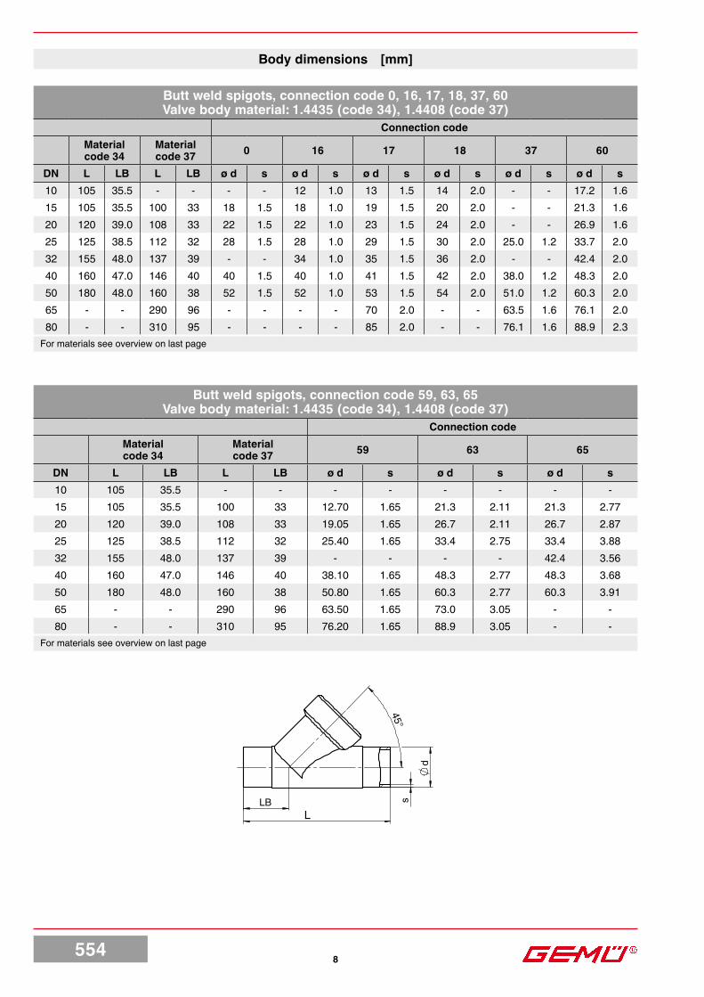
Body dimensions [mm]
Butt weld spigots, connection code 0, 16, 17, 18, 37, 60Valve body material: 1.4435 (code 34), 1.4408 (code 37)
Connection codeMaterial code 34
Material code 37 0 16 17 18 37 60
DN L LB L LB ø d s ø d s ø d s ø d s ø d s ø d s10 105 35.5 - - - - 12 1.0 13 1.5 14 2.0 - - 17.2 1.615 105 35.5 100 33 18 1.5 18 1.0 19 1.5 20 2.0 - - 21.3 1.620 120 39.0 108 33 22 1.5 22 1.0 23 1.5 24 2.0 - - 26.9 1.625 125 38.5 112 32 28 1.5 28 1.0 29 1.5 30 2.0 25.0 1.2 33.7 2.032 155 48.0 137 39 - - 34 1.0 35 1.5 36 2.0 - - 42.4 2.040 160 47.0 146 40 40 1.5 40 1.0 41 1.5 42 2.0 38.0 1.2 48.3 2.050 180 48.0 160 38 52 1.5 52 1.0 53 1.5 54 2.0 51.0 1.2 60.3 2.065 - - 290 96 - - - - 70 2.0 - - 63.5 1.6 76.1 2.080 - - 310 95 - - - - 85 2.0 - - 76.1 1.6 88.9 2.3
For materials see overview on last page
Butt weld spigots, connection code 59, 63, 65Valve body material: 1.4435 (code 34), 1.4408 (code 37)
Connection codeMaterial code 34
Material code 37 59 63 65
DN L LB L LB ø d s ø d s ø d s10 105 35.5 - - - - - - - -15 105 35.5 100 33 12.70 1.65 21.3 2.11 21.3 2.7720 120 39.0 108 33 19.05 1.65 26.7 2.11 26.7 2.8725 125 38.5 112 32 25.40 1.65 33.4 2.75 33.4 3.8832 155 48.0 137 39 - - - - 42.4 3.5640 160 47.0 146 40 38.10 1.65 48.3 2.77 48.3 3.6850 180 48.0 160 38 50.80 1.65 60.3 2.77 60.3 3.9165 - - 290 96 63.50 1.65 73.0 3.05 - -80 - - 310 95 76.20 1.65 88.9 3.05 - -
For materials see overview on last page

5549
L
d
sLB
45°
Butt weld spigots, Actuator size B, connection code 0, 16, 17, 18, 59, 60 Valve body material: Forged body (code 40)
Connection code0 16 17 18 59 60
DN L LB ø d s ø d s ø d s ø d s ø d s ø d s6 80 26.5 8 1.0 - - - - - - - - - -8 80 26.5 10 1.0 - - - - - - . . 13.5 1.6
10 80 26.5 - - 12 1.0 13 1.5 14 2.0 9.53 0.89 . .15 80 26.5 - - - - - - - - 12.70 1.65 . .
Butt weld spigots, connection code 1A, 1B, 59Valve body material: 1.4435 (code C2)
Connection code1A 1B 59
DN L LB ø d s ø d s ø d s8 105 35,5 - - 13,5 1,6 - -
10 105 35.5 13 1.5 17.2 1.6 - -15 105 35.5 19 1.5 21.3 1.6 12.70 1.6520 120 39.0 23 1.5 26.9 1.6 19.05 1.6525 125 39.5 29 1.5 33.7 2.0 25.40 1.6532 155 48.0 35 1.5 42.4 2.0 - -40 160 47.0 41 1.5 48.3 2.0 38.10 1.6550 180 48.0 53 1.5 60.3 2.0 50.80 1.6565 290 96.0 70 2.0 76.1 2.0 63.50 1.6580 310 95.0 85 2.0 88.9 2.3 76.20 1.65
* Connection code 1A: L = 100, LB = 33,5
Body dimensions [mm]

55410
45°
R
tL
LB
SW 2
Body dimensions [mm]
Threaded sockets DIN, connection code 1Valve body material: Cast bronze (code 9), 1.4408 (code 37)
DN L LB R t SW28* 65 19.0 G 1/4 9.0 17 hexagonal
10* 65 19.0 G 3/8 9.0 24 hexagonal15* 65 19.0 G 1/2 9.0 24 hexagonal10 65 16.5 G 3/8 9.0 27 hexagonal15 65 16.5 G 1/2 15.0 27 hexagonal20 75 17.5 G 3/4 16.3 32 hexagonal25 90 24.0 G 1 19.1 41 hexagonal32 110 33.0 G 1 1/4 21.4 50 octagonal40 120 30.0 G 1 1/2 21.4 55 octagonal50 150 40.0 G 2 25.7 70 octagonal65 190 46.0 G 2 1/2 30.2 85 octagonal80 220 50.0 G 3 33.3 100 octagonal
* only with actuator size B For materials see overview on last page.
Threaded sockets NPT, BS 21 Rc, connection code 3C, 3DValve body material: Cast bronze (code 9), 1.4408 (code 37)
Connection code3C 3D
DN L LB SW2 R t R t8* 65 19.0 17 hexagonal - - 1/4” NPT 10.1
10* 65 27.0 24 hexagonal - - 3/8” NPT 10.415* 65 27.0 24 hexagonal - - 1/2” NPT 13.615 65 16.5 27 hexagonal Rc 1/2 15.0 1/2” NPT 13.620 75 17.5 32 hexagonal Rc 3/4 16.3 3/4” NPT 14.125 90 24.0 41 hexagonal Rc 1 19.1 1” NPT 17.032 110 33.0 50 octagonal Rc 1 1/4 21.4 1 1/4” NPT 17.540 120 30.0 55 octagonal Rc 1 1/2 21.4 1 1/2” NPT 17.350 150 40.0 70 octagonal Rc 2 25.7 2” NPT 17.865 190 46.0 85 octagonal Rc 2 1/2 30.2 2 1/2” NPT 23.780 220 50.0 100 octagonal Rc 3 33.3 3” NPT 25.8
* only with actuator size B For materials see overview on last page.

55411
L
45°
R
tLB
R
t t
R H
2 LE
SW2
Body dimensions [mm]
Threaded spigots, connection code 9 Valve body material: Cast bronze (code 9), investment casting (code 37), Forged body (code 40)
DN L LB t R6* 65 19 12 G 1/48* 65 19 12 G 3/8
10* 65 19 12 G 1/215* 65 19 12 G 3/415 90 25 12 G 3/420 110 30 15 G 125 118 30 15 G 1 1/432 130 38 13 G 1 1/240 140 35 13 G 1 3/450 175 50 15 G 2 3/865 216 52 15 G 380 254 64 18 G 3 1/2
* only with actuator size B For materials see overview on last page.
Threaded sockets DIN, connection code 1, 3D / Angle bodyValve body material: 1.4408 (code 37)
Connection code 1 Connection code 3DDN SW2 LE H2 R t R t15 27 30 30.0 G 1/2 15.0 1/2” NPT 13.620 32 35 37.5 G 3/4 16.3 3/4” NPT 14.125 41 41 41.0 G 1 19.1 1” NPT 17.032 50 50 48.0 G 1 1/4 21.4 1 1/4” NPT 17.540 55 50 55.0 G 1 1/2 21.4 1 1/2” NPT 17.350 70 60 62.0 G 2 25.7 2” NPT 17.8

55412
LBL
45°
d1 d3
FTF
D
L
45°
LB
k
Clamp connections, connection code 80, 82, 86, 88Valve body material: 1.4435 (code 34)
DN NPSConnection code Connection code
LB L82 86 88 80
ø d1 ø d3 ø d1 ø d3 ø d1 ø d3 LB L ø d1 ø d315 1/2“ 47.5 130 18.1 50.5 16 34.0 9.40 25.0 33.5 101.6 9.40 25.020 3/4“ 54.0 150 23.7 50.5 20 34.0 15.75 25.0 30.0 101.6 15.75 25.025 1“ 56.0 160 29.7 50.5 26 50.5 22.10 50.5 33.0 114.3 22.10 50.532 1 1/4“ 62.0 180 38.4 64.0 32 50.5 - - - - - -40 1 1/2“ 67.0 200 44.3 64.0 38 50.5 34.80 50.5 37.0 139.7 34.80 50.550 2“ 73.0 230 56.3 77.5 50 64.0 47.50 64.0 36.5 158.8 47.50 64.0
Body dimensions [mm]
Flanges, connection code 13, 47 Valve body material: 1.4435 (code 34)
Connection code 13 Connection code 47
DN FTF LB ø D ø L ø k Number of bolts ø D ø L ø k Number
of bolts
15 210 72 95 14 65 4 89.0 15.7 60.5 420 280 78 105 14 75 4 98.6 15.7 69.8 425 280 77 115 14 85 4 108.0 15.7 79.2 432 310 89 140 18 100 4 117.3 15.7 88.9 440 320 91 150 18 110 4 127.0 15.7 98.6 450 330 95 165 18 125 4 152.4 19.1 120.7 4

55413
Overview of metal bodies for GEMÜ 554 Actuator size BThreaded connections Spigots
Connection code 1 9 3D 0 16 17 18 59 60Material code 37 37 40 37 40 40 40 40 40 40
DN 6 - - X - X - - - - -DN 8 X X - X X - - - - X
DN 10 X X - X - X X X X -DN 15 X X - X - - - - X -
Overview of metal bodies for GEMÜ 554 Actuator size 0 - 4Spigots
Connection code 0 16 17 18 1A 1B 37 59 60 63 65
Material code 34 34 34 37 34 C2 C2 34 37 34 37 C2 34 37 37 34
DN 8 - - - - - - X - - - - - - - - -DN 10 - X X - - X X - - - - - X - - -DN 15 X X X X X X X - - X - X X X X XDN 20 X X X X X X X - - X - X X X X XDN 25 X X X X X X X X - X - X X X X XDN 32 - X X X X X X - - - - - X X - XDN 40 X X X X X X X X - X - X X X X XDN 50 X X X X X X X X - X - X X X X XDN 65 - - - X - X X - X - X X - X X -DN 80 - - - X - X X - X - X X - X X -

For further globe valves, accessories and other products please see our Product Range catalogue and Price List. Contact GEMÜ
VALVES, MEASUREMENTAND CONTROL SYSTEMS
GEMÜGebr.Müller · ApparatebauGmbH&Co.KG · Fritz-Müller-Str.6-8 · D-74653 Ingelfingen-Criesbach ·Telefon +49(0)7940/123-0 ·Telefax +49(0)7940/[email protected] · www.gemu-group.com
Subj
ect t
o al
tera
tion
· 09/
2018
· 88
0487
46Sh
ould
ther
e be
any
dou
bts o
r misu
nder
stan
ding
s, th
e G
erm
anve
rsio
n of
this
data
shee
t is th
e au
thor
itativ
e do
cum
ent!
All r
ight
s in
clud
ing
copy
right
and
indu
stria
l pr
oper
ty ri
ghts
are
exp
ress
ly re
serv
ed.
Overview of metal bodies for GEMÜ 554 Actuator size 0 - 4Threaded connections Clamp Flanges
Connection code 1 3C 9 3D 80 82 86 88 13 47
Material code 9 37 37 37 9 37 9 37 37 34 34 34 34 34 34
Body configuration
2/2-way body
Angle body
2/2-way body
Angle body
DN 10 - X - - - - - - - - - - - - -DN 15 X X X X X X X X X X X X X X XDN 20 X X X X X X X X X X X X X X XDN 25 X X X X X X X X X X X X X X XDN 32 X X X X - X X X X - X X - X XDN 40 X X X X X X X X X X X X X X XDN 50 X X X X X X X X X X X X X X XDN 65 X X - X X X - X - - - - - - -DN 80 X X - X X X - X - - - - - - -