SECTION XXXXX LATCHWAYS MANSAFE HORIZONTAL LIFELINE …
33
DIVISION 11– EQUIPMENT SECTION XXXXXX – MAINTENANCE AND FALL PROTECTION SYSTEMS 2/6/2019 XXXXX - 1 SECTION XXXXX LATCHWAYS MANSAFE HORIZONTAL LIFELINE FALL PROTECTION SYSTEM PART 1 GENERAL 1.1 SYSTEM DESCRIPTION A. Type of system required: Horizontal Lifeline (HLL) B. System location: Roof/ Wall/ Tower/ Etc… C. Maximum number of workers on system at one time: ## D. Systems environmental exposure: What are the service conditions (indoors, outdoors, corrosive environment)? What materials will be required (steel, hot dip galvanizing, stainless steel, marine grade stainless etc…)? E. Workers task while on the system: Workers will walk along edge. Occasionally, workers are required to look over the edge. While walking, workers need to carry heavy objects. F. Type of fall protection required: Fall Restraint and Fall Arrest G. Range of movement while on the system: Uninterrupted movement throughout the entire length of the system H. Additional components: All attaching devices necessary for # workers. I. Insurances required: Commercial Liability and Workers’ Comp. 1.2 RELATED SECTIONS A. Section 03300 - Cast-In-Place Concrete B. Section 03400 - Pre-Cast Concrete C. Section 05100 – Structural Metal Framing D. Section 05400 – Cold Formed Metal Framing E. Section 05310 - Metal Deck F. Section 06100 – Rough Carpentry G. Section 07510 - Built-Up Roofing H. Section 07700 - Roof Specialties and Accessories
Transcript of SECTION XXXXX LATCHWAYS MANSAFE HORIZONTAL LIFELINE …
DIVISION 11– EQUIPMENT SECTION XXXXXX – MAINTENANCE AND FALL PROTECTION SYSTEMS
2/6/2019 XXXXX - 1
SECTION XXXXX
LATCHWAYS MANSAFE HORIZONTAL LIFELINE FALL PROTECTION SYSTEM
PART 1 GENERAL
1.1 SYSTEM DESCRIPTION
A. Type of system required: Horizontal Lifeline (HLL)
B. System location: Roof/ Wall/ Tower/ Etc…
C. Maximum number of workers on system at one time: ##
D. Systems environmental exposure: What are the service conditions (indoors, outdoors, corrosive environment)? What materials will be required (steel, hot dip galvanizing, stainless steel, marine grade stainless etc…)?
E. Workers task while on the system: Workers will walk along edge. Occasionally, workers are required to look over the edge. While walking, workers need to carry heavy objects.
F. Type of fall protection required: Fall Restraint and Fall Arrest
G. Range of movement while on the system: Uninterrupted movement throughout the entire length of the system
H. Additional components: All attaching devices necessary for # workers.
I. Insurances required: Commercial Liability and Workers’ Comp.
1.2 RELATED SECTIONS
A. Section 03300 - Cast-In-Place Concrete
B. Section 03400 - Pre-Cast Concrete
C. Section 05100 – Structural Metal Framing
D. Section 05400 – Cold Formed Metal Framing
E. Section 05310 - Metal Deck
F. Section 06100 – Rough Carpentry
G. Section 07510 - Built-Up Roofing
H. Section 07700 - Roof Specialties and Accessories
DIVISION 11– EQUIPMENT SECTION XXXXXX – MAINTENANCE AND FALL PROTECTION SYSTEMS
2/6/2019 XXXXX - 2
I. Section 11010 - Maintenance Equipment
1.3 REFERENCES
A. Occupational Safety & Health Administration (OSHA)
1. 29 CFR 1910.28(b)(1) & 29 CFR 1926.501(b)(1) - Occupational Health and Safety Standards General Industry & Construction: Duty to have fall protection
2. 29 CFR 1910.140(c)(11)(i-ii) & 29 CFR 1926.502(d)(8) - Safety and Health Regulations for General Industry & Construction: Horizontal Lifeline Design Requirements.
3. 29 CFR 1910.140(c)(13)(i-ii) & 29 CFR 1926.502(d) (15) (i-ii) - Safety and Health Regulations for General Industry & Construction: Anchorage Design Requirements.
4. 29 CFR 1910.66 (e)(1)(i) - General Industry: Powered Platform Installations -Affected parts of buildings.
B. American National Standards Institute (ANSI)
1. Z359.0 [2012] – Definitions and Nomenclature Used for Fall Protection and Fall Arrest.
2. Z359.1 [2007] – Safety Requirements for Personal Fall Arrest Systems, Subsystems and Components
3. Z359.2 [2007] – Minimum Requirements for a Comprehensive Managed Fall Protection Program
4. Z359.3 [2007] – Safety Requirements for Positioning and Travel Restraint Systems.
5. Z359.4 [2007] – Safety Requirements for Assisted-Rescue and Self-Rescue Systems, Subsystem and Components.
6. Z359.6 [2009] – Specifications and Design Requirements for Active Fall Protection Systems.
7. Z359.12 [2009] – Connecting Components for Personal Fall Arrest Systems
8. Z359.13 [2009] – Personal Energy Absorbers and Energy Absorbing Lanyards
9. Z359.14 [2012] – Safety Requirements for Self-Retracting Devices for Personal Fall Arrest and Rescue Systems.

DIVISION 11– EQUIPMENT SECTION XXXXXX – MAINTENANCE AND FALL PROTECTION SYSTEMS
2/6/2019 XXXXX - 3
C. Materials, Bolting, Finishing: American Society of Testing Materials (ASTM)
1. A36 - Standard Specification for Carbon Structural Steel.
2. A500 - Standard Specification for Cold-Formed Welded and Seamless Carbon Steel Structural Tubing in Rounds and Shapes
3. A53 - Standard Specification for Pipe, Steel, Black and Hot-Dipped, Zinc-Coated, Welded and Seamless
4. A325 - Standard Specification for Structural Bolts, Steel, Heat Treated, 120/105 ksi Minimum Tensile Strength
5. A193 - Standard Specification for Alloy-Steel and Stainless Steel Bolting for High Temperature or High Pressure Service and Other Special Purpose Applications
6. A123 - Standard Specification for Zinc (Hot-Dip Galvanized) Coatings on Iron and Steel Products
7. A666 - Standard Specification for Austenitic Stainless Steel Sheet, Strip, Plate, and Flat Bar.
D. American Welding Society (AWS) D1.1/D1 - Structural Welding Code – Steel
E. Design Standards
1. American Institute of Steel Construction (AISC) 325-11 [14th ed.] – Steel Construction Manual
2. National Design Specification (ANSI/NDS) [2012] – Wood Construction Manual
3. International Building Code (IBC) [2012] – Building Design Manual
4. American Society of Civil Engineers (ASCE/SEI) 7-10 [2010] – Minimum Design Loads for Buildings and Other Structures
5. American Concrete Institute (ACI) 318-11 Building Code Requirements for Structural Concrete.
1.4 PERFORMANCE
A. System shall comply with 1.1 System Description
B. Performance Requirements
1. The Fall Protection System shall be designed to allow users to walk the entire length of the system without having to disconnect from the system

DIVISION 11– EQUIPMENT SECTION XXXXXX – MAINTENANCE AND FALL PROTECTION SYSTEMS
2/6/2019 XXXXX - 4
to pass through intermediate support points. The system shall be designed to support required number of users in case of a fall and to prevent the users from free falling more than 6 feet. All components shall be designed by the fall protection system supplier and shall meet the applicable requirements of ANSI and applicable OSHA regulations.
2. Structural Performance:
a. Structure supporting Latchways Horizontal Lifeline system must be capable of withstanding design loads as required by governing regulations and codes. Where component design loads are specified herein, they represent design minimum requirements.
b. All horizontal lifelines shall be designed with a minimum 2:1 safety factor.
1.5 DESIGN
A. Design Requirements
1. Fall protection horizontal lifelines shall comply with current applicable OSHA, ANSI, and state regulations and standards.
2. The fall protection system and any supporting structure shall be designed by:
Latchways PLC Phone: 011-44-1380-732700 15401 Vantage Parkway West, Website: www.latchways.com Suite 120 Houston, TX, 77032 E-mail: [email protected].
Gravitec Systems Inc. Phone: 1-800-755-8455 21291 Urdahl Road NW, Website: www.gravitec.com Poulsbo, WA 98370-7124 E-mail: [email protected].
3. General Requirements:
a. Horizontal lifelines shall be designed and installed, under the supervision of a Qualified Person, as part of a complete personal Fall Protection system.
b. The horizontal lifeline must be level (less than a 5% grade).
c. Engineers shall, at minimum determine the performance of the system when a fall occurs on the shortest span (largest forces) and the longest span (largest total fall distance) in the system.
d. The HLL(s) constant force energy absorbers shall not be used to limit the maximum arrest force of the worker. The HLL(s) constant

DIVISION 11– EQUIPMENT SECTION XXXXXX – MAINTENANCE AND FALL PROTECTION SYSTEMS
2/6/2019 XXXXX - 5
force energy absorbers shall be used only to control or reduce the maximum arrest load on the structure.
e. Anchorages for horizontal lifelines systems shall be verified and designed, prior to use, by a Qualified Person with experience and training in designing and using horizontal lifelines systems.
f. HLL(s) shall satisfy the seismic conditions for nonstructural components as described by ASCE/SEI 7 and the most current edition of the IBC. No exceptions can be taken if the system is required to function for life-safety purposes after an earthquake.
g. The fall arrest system shall consist of a stainless steel safety cable attached to the structure. The cable shall be continuous or shall have swaged splices, which allow the user to pass without disconnecting from the system.
h. Brackets and supports shall be attached to the structure with appropriate anchors of proper size to adequately support the intended loaded.
i. The HLL(s) shall comply with Latchways design requirements.
4. Restraint HLL(s) shall be designed per ANSI Z359.2 & ANSI Z359.6:
a. The HLL(s) shall prevent workers from reaching and falling into any open hole or off the edge of a working surface.
b. The horizontal lifeline shall comply with the requirements for fall arrest horizontal lifelines as indicated in this document.
c. Where a worker is using a full body harness the force on the worker’s body shall not exceed 400 lbs.
d. HLL constant force energy absorbers may be used in travel restraint systems; provided that the engineer has determined that the restraint forces will not cause the HLL constant force energy absorbers to deploy and ensures that the deflection of the wire rope in combination with other deformations of the restraint system will not permit the worker(s) to reach the fall hazard.
e. The use of fall restraint systems shall be limited to surfaces at or less than a slope of 4:12 from the horizontal. This is so a fall will not result in dynamic loading on the fall restraint system or where the authorized person could end up being suspended vertically from the system.
4. Fall Arrest HLL(s) shall be designed per ANSI Z359.2 & ANSI Z359.6:

DIVISION 11– EQUIPMENT SECTION XXXXXX – MAINTENANCE AND FALL PROTECTION SYSTEMS
2/6/2019 XXXXX - 6
a. The selection, design, and installation of fall arrest horizontal lifelines shall be performed under the supervision of a Qualified Person.
b. Fall arrest horizontal lifelines shall have the strength capable of sustaining static loads applied to the wire rope of at least two times the maximum arresting force.
c. When more than one user is attached to a horizontal lifeline, the load on the lifeline can be determined using either lumped mass or sequential fall as described in ANSI Z359.6 [6.3.6]
d. The swing fall shall comply with ANSI Z359.6 [5.3]
e. The clearance safety margin shall comply with ANSI Z359.6 [7.2.6.2]
B. Sub-System Requirements
1. Harnesses and Vertical Lifelines (VLLs) used with the system shall comply with ANSI Z359.1
2. Connecting Components (carabiners and snaphooks) used with the system shall comply with ANSI Z359.12
3. Energy Absorbing Lanyards (EALs) used with the system shall comply with ANSI Z359.13
4. Self Retracting Lifelines (SRLs) used with the system shall comply with ANSI Z359.14
C. Horizontal lifelines shall be used exclusively for their designed use and shall be marked to prevent other uses.
D. The design shall take into consideration the potential uses of and loads on the horizontal lifeline, in order to facilitate the prompt rescue of workers who may fall while attached to the system.
E. The manufacturer shall test the HLL design using a 660lb weight on various roof structures.
F. Each batch of inclined HLLs shall be static, dynamic, salt spray, and x-ray tested.
G. Each component of the inclined HLL shall be batch marked or individually serial numbered.
1.6 SUBMITTALS
A. Submit under provisions of Section ##### – Submittal Procedures
DIVISION 11– EQUIPMENT SECTION XXXXXX – MAINTENANCE AND FALL PROTECTION SYSTEMS
2/6/2019 XXXXX - 7
B. Product Data: Latchways’ data sheet on each product to be used, including:
1. Preparation instructions and recommendations.
2. Storage and handling requirements and recommendations
3. Installation methods
C. Drawings and Calculations:
1. Drawings:
a. Show the layout of the system including where the system is located and the complete assembly of all components.
b. Include a specification of the number, location, and qualifications of workers using the system.
c. Clearly specify the equipment dimensions, materials, fabrication details, hardware, and installation instructions.
2. Calculations:
a. Calculations shall be prepared under the supervision of a registered Professional Engineer and Qualified Person.
b. Include a statement defining the type of system and indicating that the design is in accordance with the requirements of ANSI Z359.6.
3. The Professional Engineer who oversaw the design of the system shall affix their professional seal to each drawing and calculation package issued.
D. Operation and Maintenance Data shall be prepared per Z359.2 & ANSI Z359.6:
1. Include complete list of equipment replacement parts; identify each entry with the equipment description and part numbers.
2. Include technical information for servicing equipment.
3. Include legible “as-constructed” drawings of the installed system.
4. Include installation date and system owner’s name and address.
5. Include detailed operating procedures:
a. Written by a Qualified or Competent Person.
b. Identifying the horizontal lifelines location

DIVISION 11– EQUIPMENT SECTION XXXXXX – MAINTENANCE AND FALL PROTECTION SYSTEMS
2/6/2019 XXXXX - 8
c. Stating any safety precautions that shall be followed during access and egress.
d. Describing the limitation on use of system: maximum load, designated equipment, required clearance and maximum number of persons permitted to be attached to the system at one time.
e. Instructions for inspection, maintenance, and retirement of the system and all of its components, including how often inspection and maintenance are to be performed and a description of the qualifications required for persons performing these tasks.
f. Procedure for inspection:
I. Required or recommended inspection intervals.
II. Detailed instruction for inspecting each component of the system.
III. Description of acceptance or rejection criteria, including retirement criteria, of each component of the system.
IV. Fall protection procedures shall include a requirement that any incidents, including accidents or near misses, be investigated to determine if procedures can be improved.
6. Provide or direct the owner of the system or the employer of the workers using the system to develop and implement a rescue plan before the system is used.
1.7 QUALITY ASSURANCE
A. Single Source: Obtain all materials and equipment required under this section from a single supplier.
B. Designer/Installer Qualifications: Engage a single firm to assume undivided responsibility for the design and fabrication of all fall protection system components. Firm shall have a minimum of 5 years documented experience in the fabrication of such components similar to that required for this project. Additionally, the firm shall have a minimum of 5 years documented experience in the installation of such components and who offers a regular inspection and maintenance service on such systems.
C. Design Engineer: Employ a firm with a minimum of 10 years experience designing fall protection systems with a minimum of 5 systems installed in the previous 12 months. Who employs a registered Professional Engineer (PE), with evidence of being the principal PE on at least 3 fall arrest systems which have been in use for no less than 1 year prior to bid closing date.
DIVISION 11– EQUIPMENT SECTION XXXXXX – MAINTENANCE AND FALL PROTECTION SYSTEMS
2/6/2019 XXXXX - 9
D. Professional Engineer and Fall Protection Qualified Person: Shall oversee the fall protection systems’ design, such that all component items meet the “Structural Performance” requirements, including sizing and spacing of all attachments to the building structure and verify the design is compliant with all applicable OSHA and ANSI standards. Additionally, they must prepare, stamp and sign all required calculations; while also approving the system designer’s drawings
E. Welding to be executed by certified welders in accordance with AWS requirements.
1.8 DELIVERY, STORAGE & HANDLING
A. Material delivery shall be coordinated with all effected entities.
B. Storage and Protection:
1. Store originally packaged materials in a cool, dry, and protected location.
2. Materials shall be in new condition and show no signs of damage.
1.9 SEQUENCING
A. Ensure that products of this section are supplied to affected trades in time to prevent interruption of construction progress.
1.10 WARRANTY
A. Manufacturer's standard year warranty for materials and workmanship.
PART 2 PRODUCTS
2.1 MANUFACTURERS
A. Manufacturers shall comply with the Quality Assurance section of this documentation.
B. All supporting structure which connects the horizontal lifeline to the super structure shall be designed by:
Gravitec Systems Inc. Phone: 1-800-755-8455 21291 Urdahl Road NW, Website: www.gravitec.com Poulsbo, WA 98370-7124 E-mail: [email protected].
2.2 PRODUCTS
A. Latcheways PLC 15401 Vantage Parkway West, suite 120 Houston, TX, 77032
DIVISION 11– EQUIPMENT SECTION XXXXXX – MAINTENANCE AND FALL PROTECTION SYSTEMS
2/6/2019 XXXXX - 10
2.3 MATERIALS
A. Product
1. The system shall be a complete and turnkey complying with the performance and design criteria of this document.
2. The HLL(s) shall be the product of Latchways PLC.
3. Components: All system connectors, cables and bolts shall be stainless steel Type 316 or epoxy coated aluminum. Fabricated supports required for additional support may be carbon steel with a corrosion resistant coating. However a faying surface shall be used to prevent galvanic reactions.
4. Post Base Plate Connectors: Provide complete with required components for weatherproof mounting to the following surfaces:
a. Standing Seam Roof Type.
b. Composite Ribbed Roofing Type.
c. Metal Roofing Type.
d. Insulated Roof Deck Type.
e. Concrete Deck Type.
f. Timber Deck Type.
g. Non-Penetrating.
5. The Latchways Fall Protection System shall be attached to the supporting structure with appropriate fasteners. The fasteners shall be designed to support a load on the fall protection system of 2 times the maximum design load without failure.
6. Provide all designed sub-system items per Section 1.5 (B) of this document.
B. Supporting Structure
1. Structural Components shall comply with the applicable standards:
a. Structural Steel: ASTM A36
b. Structural Tubing: ASTM A500 Grade B
c. Structural Bars, Plates, Shapes, and Sheet Piling: ASTM A6
DIVISION 11– EQUIPMENT SECTION XXXXXX – MAINTENANCE AND FALL PROTECTION SYSTEMS
2/6/2019 XXXXX - 11
d. Piping: ASTM A53
2. Fasteners shall comply with the applicable standards:
a. Structural Bolts: ASTM A325
b. Alloy-Steel and Stainless Steel Bolting: ASTM A193
3. Flashing and Sealing Material shall comply with the applicable standards:
4. Material substitutions shall be better than or equal to the requirements found in this section.
5 Fabrication
a. Fabricate work true to dimension, square, plumb, level, and free from distortion or defects detrimental to performance.
b. Coordinate the system with supporting structure.
c. Welding:
I. AWS D 1.1 as applicable.
II. If Butt welds are used, then surplus welding material is to be ground off to ensure exposed surfaces are smooth. Fillet welds shall not be ground.
III. Slag is to be removed from the materials surface.
6 Finishes
a. Hot Dipped Galvanizing: Comply with ASTM A123.
b. Powder Coat: Safety Yellow
2.4 HORIZONTAL LIFELINE DESIGN
A. Horizontal lifeline design shall comply with the Design Requirement section of this document.
B. Steel design shall comply with AISC 14th ed.
C. Wood design shall comply with ANSI/NDS [2005]
D. Concrete design shall comply with ACI [2008]
E. Fall protection systems attached onto an existing or new structure shall comply with IBC [2009] and ASCE/SEI [2010]

DIVISION 11– EQUIPMENT SECTION XXXXXX – MAINTENANCE AND FALL PROTECTION SYSTEMS
2/6/2019 XXXXX - 12
PART 3 EXECUTION
3.1 INSTALLATION
A. Installation shall be performed by:
Gravitec Systems Inc. Phone: 1-800-755-8455 21291 Urdahl Road NW, Website: www.gravitec.com Poulsbo, WA 98370-7124 E-mail: [email protected].
B. Install in accordance with approved shop drawings and manufacturer’s instructions.
C. The Latchways Fall Protection System shall be installed under the direction of manufacturer’s authorized trained personnel and under the supervision of a Qualified Person
D. Install anchorages and fasteners in accordance with their manufacturer’s recommendations to obtain the allowable working loads published in the product literature and in accordance with this specification.
E. Do not load or stress the Latchways Fall Protection System until all materials and fasteners are properly installed and ready for service.
F. Where bolting is used for fastening, no fewer than three threads are to be exposed and the nut is to be positively locked using a thread-locking fluid or the double nutting technique.
G. Dissimilar materials with greater than 0.15V shall be separated by a faying surface.
H. Constant Force posts must be secured to roof surface with waterproof mechanical connectors as approved.
3.2 FIELD QUALITY CONTROL
A. After the Latchways Fall Protection System is installed and properly tensioned, Latchways approved authorized Qualified or Competent Person shall inspect and operate the system and shall make all final adjustments for proper operation.
3.3 ADJUSTMENTS AND FINAL INSPECTION
A. Verify that all manufactured units have been installed in accordance with specifications and details, and will function as intended. Adjust any items where necessary to ensure proper operation.
B. Provide a complete drawing set with any revisions to the design or layout of the horizontal lifelines during installation.

DIVISION 11– EQUIPMENT SECTION XXXXXX – MAINTENANCE AND FALL PROTECTION SYSTEMS
2/6/2019 XXXXX - 13
3.4 OPERATOR TRAINING
A Provide a minimum of 4 hours of operator training after system has been installed. Training is to be for the users of the system conducted at the installation site.
3.5 MAINTENANCE, INSPECTION AND TESTING
A. Provide manufacturer maintenance, inspection and testing instructions.
B. Provide documentation that is consistent with applicable OSHA and ANSI standards.
END OF SECTION

ManSafe® for Roofi ngFall protection systems
for rooftop maintenance
Constant Force® PostFreestanding Constant Force® PostWalkSafe®
VersiRail®
Ap
plicati
on b
roch
ure

2
Falls from height are the single biggest cause of death and one of the biggest causes of serious injury in the workplace today. For businesses whose workers need to operate quickly and effectively at height, fall protection is already a major issue—and this will become increasingly important as regulatory authorities introduce ever-stricter rules governing:
• Where height safety should be implemented
• The systems that are acceptable for use
• Who is responsible for ensuring worker safety
Introduction
CDM Co-ordinator
Principal Contractors/Sub-Contractor
Client/Building Owner
Designer/Architect
Health and Safety Manager
Facilities Manager
Latchways plc—global leaders in fall protection
What you need to doThe offi cial advice to duty-holders can be summarised as follows:
• Avoid work at height, where possible
• When working at height is essential, ensure that workers are not exposed to unnecessary risks
• Where it is not possible to eliminate the risk of falling, use a suitable fall protection system to minimise the consequences of a fall
Are you responsible?
The answer could well be ‘Yes’. According to the health and safety legislation these people are ‘duty-holders’—responsible for ensuring adequate fall protection and potentially liable in the event of an accident.

3
All roofs require some form of access for:• General maintenance
• Structural/performance checks for warranty maintenance
• Plant access
Rooftop fall protection examples1 Roof Access:
Access via ladders and roof hatches
2 Roof Edges:
Access required for gutter cleaning, leakage checks, inspection and maintenance to the rest of the roof
3 Roof Plant:
Air conditioning units, satellite dishes and solar panels all need regular checks
4 Walkways:
Walkways should be accompanied by a fall protection system
5 Roofl ights:
Fall protection required for cleaning and maintenance
1 2
3
4 5
ManSafe for Roofi ngWhere is fall protection required?

4
Latchways has developed an easy-to-use assessment method to help establish what type of system is required for permanent access. There are a number of key considerations that will help decide what type of system needs to be installed and therefore minimise risk:
• Experience of the worker(s) accessing the system
• Number of worker(s) accessing the system
• Duration of the worker(s) on the system
• Frequency of use
In most cases, unless specialist rope access is required, it is best practice to assume that the worker has only basic experience. The illustrations below are designed merely as a guide to the options that are available. In all cases a propriety walkway, such as WalkSafe® is recommended to accompany the fall protection system to provide a safe means of access to the place of work. WalkSafe also ensures the rooftop is protected from any possible damage caused during regular cleaning and maintenance of plant, gutters, down pipes etc.
What type of fall protection system should you install?
Solution: Fall Arrest**
Lanyard adjustment required (ridge system with anti-pendulum posts)
Training Requirement: Advanced
Solution: Fall Restraint*
No lanyard adjustment required (perimeter system)
Training Requirement: Basic
Solution: Fall Arrest**
No lanyard adjustment required (perimeter system with fall hazards present)
Training Requirement: Basic
Solution: Guardrail
Freestanding collective protection
Training Requirement: None
*Restraint system—system is located so a worker on a fi xed-length lanyard cannot reach any fall hazard. **Arrest system—system location is restricted and fall hazards can be reached by a worker on a fi xed or variable length lanyard.
Latchways’ in-house design team can further advise on the most appropriate system for your particular requirement. For advice on system design and specifi cation, email Latchways at [email protected].

5
In April 2005 the HSE published the Work at Height Regulations (WAHR). These regulations brought together the relevant parts of the Construction (Health, Safety and Welfare) Regulations 1996 (CHSWR), the Workplace (Health, Safety and Welfare) Regulations 1992 and the Construction (Design and Management) Regulations (CDM).
These regulations all have references to working at height and are incorporated within the WAHR. The WAHR also implement the European Community Temporary Work at Height Directive (2001/45/EC), which is the second amendment to EC Directive (1989/655/EEC) on the provision and use of work equipment. These were further updated in 2007.
The legislation recognises that fall protection specifi cs are diffi cult to determine and hence legislate for. It allows some fl exibility in interpretation and guidance but those responsible for providing adequate fall protection must be able to demonstrate that they have minimised risk, specifi ed suitable equipment, considered the ability of the user and appreciated the conditions in which the system is likely to be used. The duty-holder must have evidence that these issues have been considered and addressed in the risk assessment.
In addition to these key pieces of legislation, the Booklet HSG 33 ‘Health and Safety in Roof Work’ gives extensive guidance on how to work safely on roofs. It covers new buildings, repair, maintenance, cleaning work and demolition. It points to the principal problems, notably falls through fragile roofi ng materials and falls from unprotected roof edges and warns that many may undertake maintenance work with little or no experience of roof work or of working at height.
Construction (Design and Management) Regulations 2007 (CDM)
As with the original 1994 legislation, the Regulations continue to place duties on all those who can contribute to the health and safety of a construction project i.e. clients, designers, contractors and planning supervisors, requiring the production of certain documents, the health and safety plan and the health and safety fi le.
Specifi cally the designer’s duties include the avoidance of risk to people
1. carrying out construction work
2. cleaning & maintaining
3. using a structure as a place of work
4. demolition & dismantling
5. others who may be affected by the above
The main changes in the 2007 Regulations were made to simplify the existing system by unifying CDM and the Construction (Health, Safety & Welfare) Regulations 1996 into a single package. Additionally there is a more explicit duty on architects to eliminate hazards and reduce risks during the design stage as far as is reasonably practicable, plus there is a new duty to ensure that workplaces comply with Construction (Health, Safety and Welfare) Regulations.
ManSafe for Roofi ngWhat does the legislation say?
Latchways can advise and assist with compliance; for further information email: [email protected].

6
Constant ForceFall Protection InnovationLatchways has taken the science of Constant Force and applied it to the fall protection industry providing an easy-to-install, reliable and cost-effective solution to rooftop safety.
The principles of fall arrest are based on effective load control. A system must be able to withstand the force of a person’s fall and absorb the energy generated. Traditionally this was achieved by attaching the system to the structure of the building with the anchor point absorbing the load. This inherently caused diffi culties for designers and installers as the system location was determined by the structural elements of the building.
System installation was time consuming as fi xings had to be made from above and below. Such an installation method can create issues regarding warranties, leakage and cold bridging.
Latchways’ Constant Force post does not need to be fi xed to the building structure therefore simplifying installation (see pages 8 & 9). The Constant Force technology allows the load generated in the event of a fall to be absorbed through the entire system, as illustrated in the graph below.
Constant Force post performancecompared against Rigid Anchor
Latchways’ primary focus is to supply engineered fall protection products for all areas of industry, construction and maintenance. Installations include stadia, retail outlets, transmission towers, industrial complexes and notable sites such as Eden Project, Pier 6 at Gatwick Airport, Hong Kong Airport and Grand Central Station in New York. Latchways has worked closely with the major roofi ng manufacturers to produce a full range of fall protection systems for all designs and types of roofs.
Quality products
Forc
e (
kN
)
40
35
30
25
20
15
10
5
38
Load absorbed by Constant Force post
Load absorbed by rigid anchor

7
In addition to ‘in-house’ evaluation, Latchways’ products are tested externally by notifi ed independent test bodies. All systems are CE marked and hold EC Declarations of Conformity.
Constant Force systems are recommended and approved for use by most roofi ng manufacturers.
Details of how the systems fi t on all major roof types can be found in Latchways’ ManSafe specifi ers manual available on request or by visiting www.latchways.com.
The key European standards are:
• EN 353-1 Personal Protective Equipment (PPE) against falls from a height. Specifi cation for guided type fall arresters on a rigid anchorage line
• EN 353-2 PPE against falls from a height. Guided type fall arresters including a fl exible anchor line
• EN 341 PPE against falls from a height—Descender devices
• EN 354 PPE against falls from a height—Lanyards
• EN 355 PPE against falls from a height—Energy absorbers
• EN 358 PPE for work positioning and prevention of falls from a height—Belts for work positioning and restraint and work positioning lanyards
• EN 360 PPE against falls from a height—Retractable type fall arresters
• EN 361 PPE against falls from a height—Full body harness
• EN 362 PPE against falls from a height—Connectors
• EN 363 PPE against falls from a height—Fall arrest systems
• EN 364 PPE against falls from a height—Test methods
• EN 795 PPE against falls from a height—Anchor devices— Requirements and testing
The key standard is EN 795 which relates to the anchor devices. Developments in technology mean that the nature of the anchor device has changed. As such, Latchways conduct full roofi ng system tests (6 m x 6 m) to replicate the in-situ installation. This is a minimum requirement where top-fi xed solutions are concerned.
ManSafe for Roofi ngLegislation and equipment standards

8
Constant Force post: Fixing details
Latchways’ Constant Force systems offer a complete fall protection solution for both fall restraint and fall arrest. The simplicity of the fi xings allows a quick and easy installation providing safe solutions where workers are exposed to a fall hazard. System design can be verifi ed with Latchways’ software.
Latchways works with all major roof manufacturers. To see how posts fi x to manufacturers’ individual roofi ng systems visit www.latchways.com or ask for a ManSafe Specifi ers Manual.
Email: [email protected] for more information.
Key advantages• System technology limits load to 10 kN in the event of a fall
• Top-fi xing ensures quick and easy installation
• Reduces cold bridging aiding compliance with Part L
• Does not invalidate roofi ng warranty
• System location not restricted to buildings’ structural elements
• Option of powder coating posts to match roof
• Suitable for use on a roof pitch up to 15°
A variety of base plates are available to fi t all roof confi gurations:
Roof type Fixing dimensions (mm)
Standing-seam 300/305/333/400/500
Composite and built-up-on-site (BUOS) 250/300/333/400/500
Secret-fi x 500/532
Steel deck 210/268/300/350/459
Concrete deck 210/268/300/350/459
Timber deck 210/268/300/350/459
Constant Force post on standing-seam roofi ng
Constant Force post oncomposite/BUOS roofi ng
Constant Force post on secret-fi x roofi ng
Fixing method: 4 split clamps
Fixing method: 16 stitching screws/bulb tite rivets
Fixing method: 20 bulb tite water seal rivets
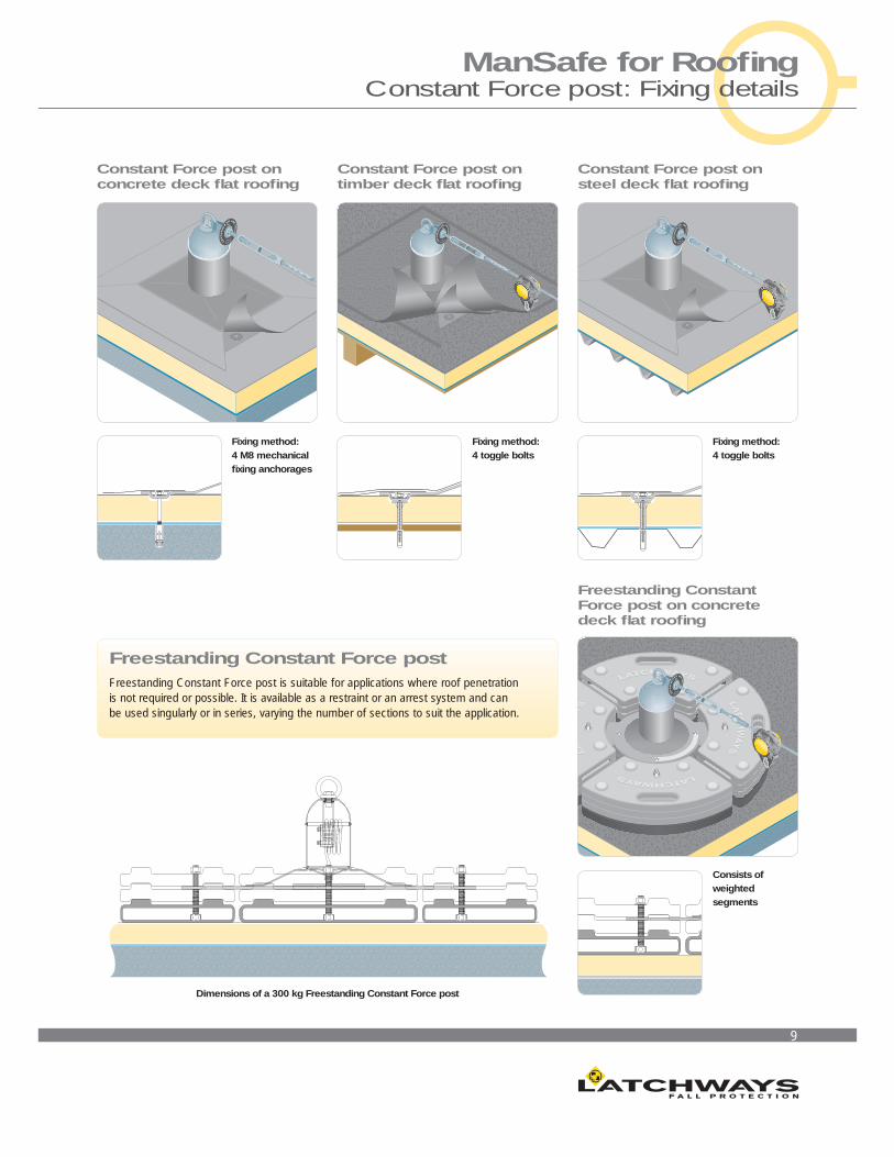
9
Freestanding Constant Force postFreestanding Constant Force post is suitable for applications where roof penetration is not required or possible. It is available as a restraint or an arrest system and canbe used singularly or in series, varying the number of sections to suit the application.
Fixing method: 4 M8 mechanical fi xing anchorages
Fixing method: 4 toggle bolts
Fixing method: 4 toggle bolts
Consists of weighted segments
Dimensions of a 300 kg Freestanding Constant Force post
Constant Force post onconcrete deck fl at roofi ng
Constant Force post ontimber deck fl at roofi ng
Constant Force post onsteel deck fl at roofi ng
Freestanding Constant Force post on concrete deck fl at roofi ng
ManSafe for Roofi ngConstant Force post: Fixing details

10
40 metres
20 m
etre
s
RIDGE
A
E
B
B
B
B
D C C C C C
C C C C C
D
D
WalkSafe system
Access hatch
Constant Force post: System design
A typical roof layout for a perimeter system is illustrated identifying the different system components. Posts must not be spaced more than 10 m apart. Designers should try to ensure that access to all areas is achieved without the requirement for PPE (Personal Protective Equipment) adjustment. Latchways provides a bespoke system design service for your project requirements.
Email: [email protected] for more information.
System componentsThe following components complete the system allowing hands-free operation. Latchways’ components are manufactured in marine-grade stainless steel and are individually numbered to allow complete traceability. Inspection and maintenance are required annually.
Transfasteners
The user, wearing a full body harness and energy-absorbing lanyard, is continuously attached to the system with a Transfastener™, which rotates allowing it to pass through the intermediate cable supports. For systems on inclines over 15° a ClimbLatch device is required instead of the Transfastener.
Turnbuckle assembly
The turnbuckle assembly provides a cable termination and method of tensioning the system. The integral indicator disc will spin when the correct tension is reached.
Swage & Clevis
The swage and clevis unit provides the method of terminating the cable at the opposite end of the system to the turnbuckle assembly.
90° Corner bracket
This one-piece corner bracket attached to an intermediate post provides an angle change of 90° within the system.
Variable bracket
This bracket attaches to an intermediate post and provides an angle change of between 0 and 80° both in the horizontal and the vertical plane.
D Ring & Hanger
The D ring and hanger form an intermediate cable support. The cable is threaded through the hanger allowing the Transfastener to travel the length of the system without disconnecting.
A. End Anchor B. Variable Anchor C. Intermediate Anchor D. Corner Anchor E. End Anchor
11
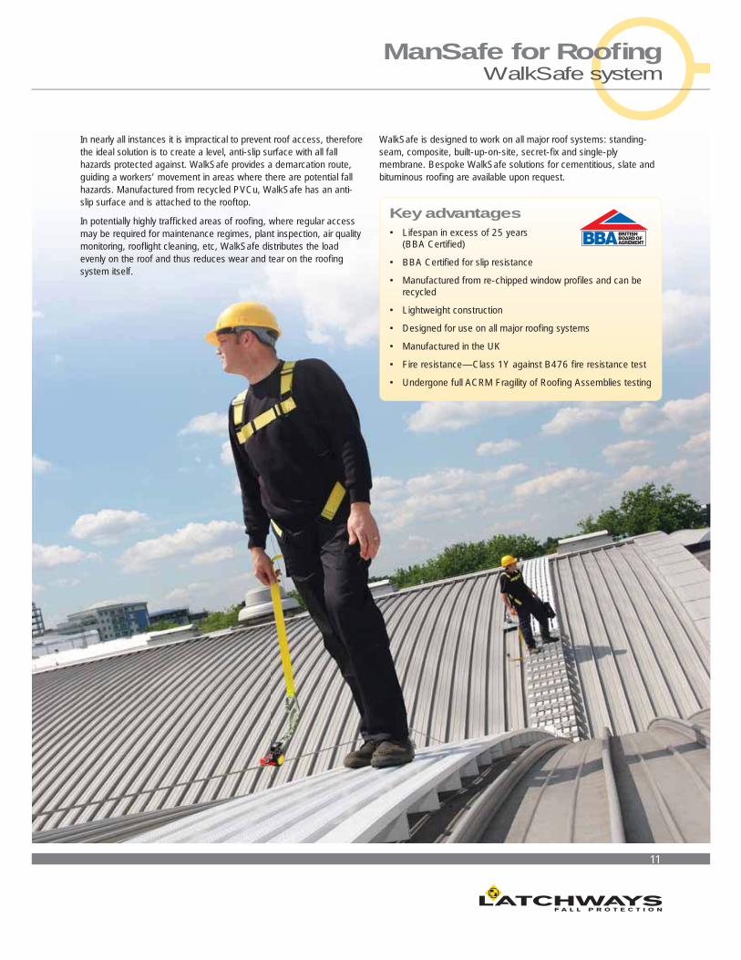
In nearly all instances it is impractical to prevent roof access, therefore the ideal solution is to create a level, anti-slip surface with all fall hazards protected against. WalkSafe provides a demarcation route, guiding a workers’ movement in areas where there are potential fall hazards. Manufactured from recycled PVCu, WalkSafe has an anti-slip surface and is attached to the rooftop.
In potentially highly traffi cked areas of roofi ng, where regular access may be required for maintenance regimes, plant inspection, air quality monitoring, roofl ight cleaning, etc, WalkSafe distributes the load evenly on the roof and thus reduces wear and tear on the roofi ng system itself.
WalkSafe is designed to work on all major roof systems: standing-seam, composite, built-up-on-site, secret-fi x and single-ply membrane. Bespoke WalkSafe solutions for cementitious, slate and bituminous roofi ng are available upon request.
Key advantages• Lifespan in excess of 25 years
(BBA Certifi ed)
• BBA Certifi ed for slip resistance
• Manufactured from re-chipped window profi les and can be recycled
• Lightweight construction
• Designed for use on all major roofi ng systems
• Manufactured in the UK
• Fire resistance—Class 1Y against B476 fi re resistance test
• Undergone full ACRM Fragility of Roofi ng Assemblies testing
ManSafe for Roofi ngWalkSafe system

12
The orientation of the WalkSafe planks within a system is described as either shortways (running across the roofi ng profi le) or longways (with the roofi ng profi le).
WalkSafe: System layout
The system can be confi gured in four ways to cover corners and change of directions:
As T-section, longways to shortways or vice versa, or as corner section either to shortways ‘end’ or longways ‘side’.
13
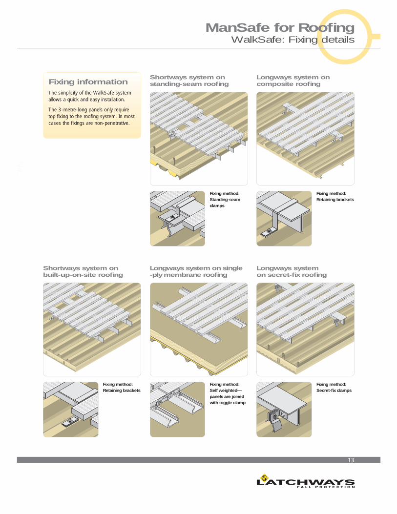
Fixing informationThe simplicity of the WalkSafe system allows a quick and easy installation.
The 3-metre-long panels only require top fi xing to the roofi ng system. In most cases the fi xings are non-penetrative.
ManSafe for Roofi ngWalkSafe: Fixing details
Fixing method: Standing-seam clamps
Shortways system onstanding-seam roofi ng
Fixing method: Retaining brackets
Longways system oncomposite roofi ng
Fixing method: Retaining brackets
Shortways system onbuilt-up-on-site roofi ng
Fixing method: Self weighted—panels are joined with toggle clamp
Longways system on single -ply membrane roofi ng
Fixing method: Secret-fi x clamps
Longways system on secret-fi x roofi ng
14
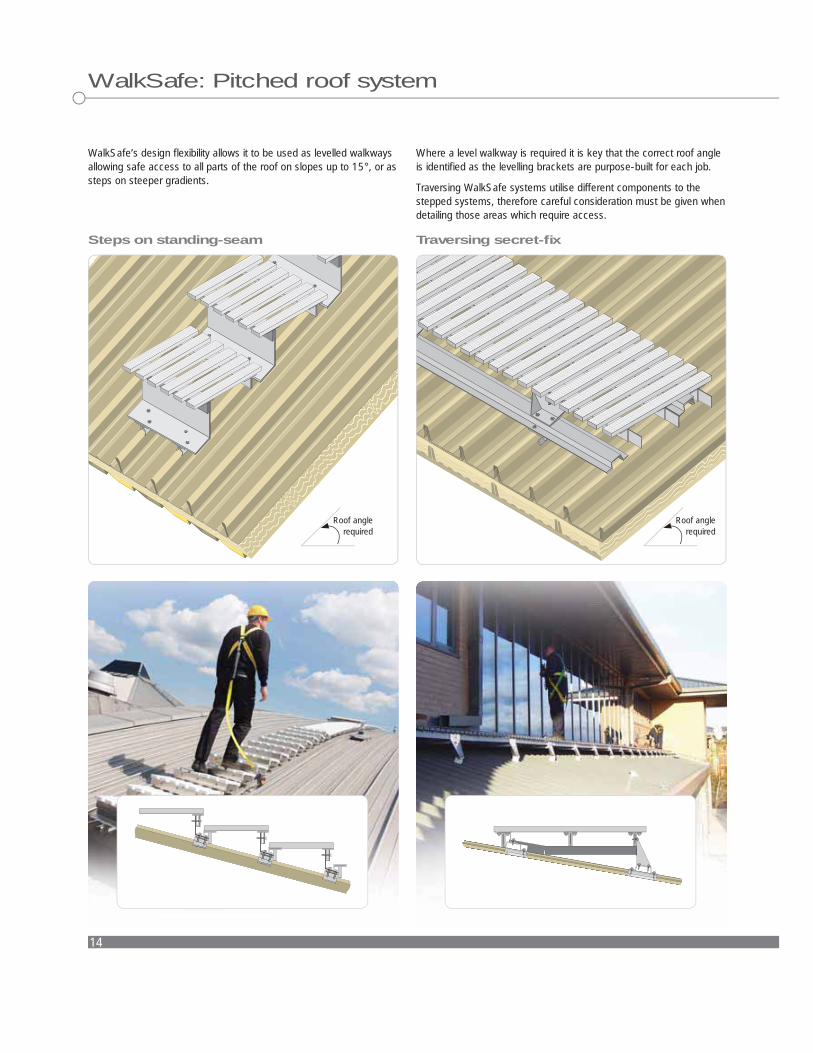
Where a level walkway is required it is key that the correct roof angle is identifi ed as the levelling brackets are purpose-built for each job.
Traversing WalkSafe systems utilise different components to the stepped systems, therefore careful consideration must be given when detailing those areas which require access.
WalkSafe’s design fl exibility allows it to be used as levelled walkways allowing safe access to all parts of the roof on slopes up to 15°, or as steps on steeper gradients.
WalkSafe: Pitched roof system
Steps on standing-seam Traversing secret-fi x
Roof angle required
Roof angle required
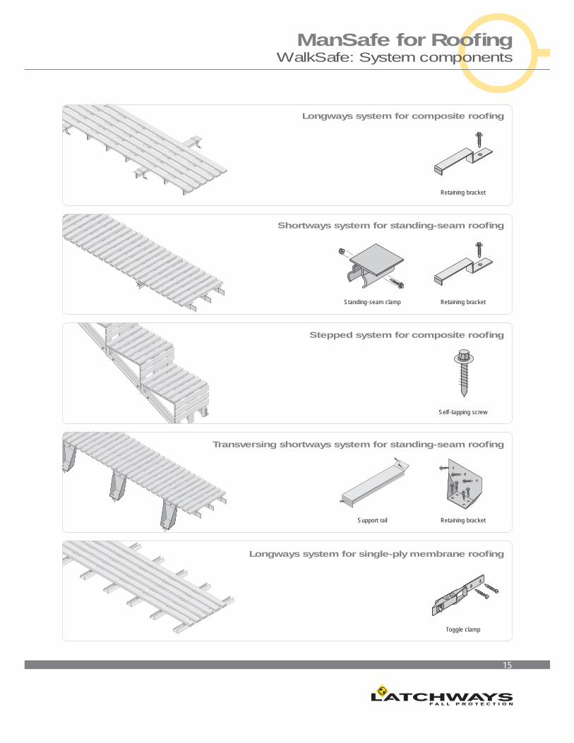
15
Longways system for composite roofi ng
Shortways system for standing-seam roofi ng
Stepped system for composite roofi ng
Transversing shortways system for standing-seam roofi ng
Longways system for single-ply membrane roofi ng
ManSafe for Roofi ngWalkSafe: System components
Standing-seam clamp
Support rail
Retaining bracket
Retaining bracket
Retaining bracket
Toggle clamp
Self-tapping screw
16
VersiRail system
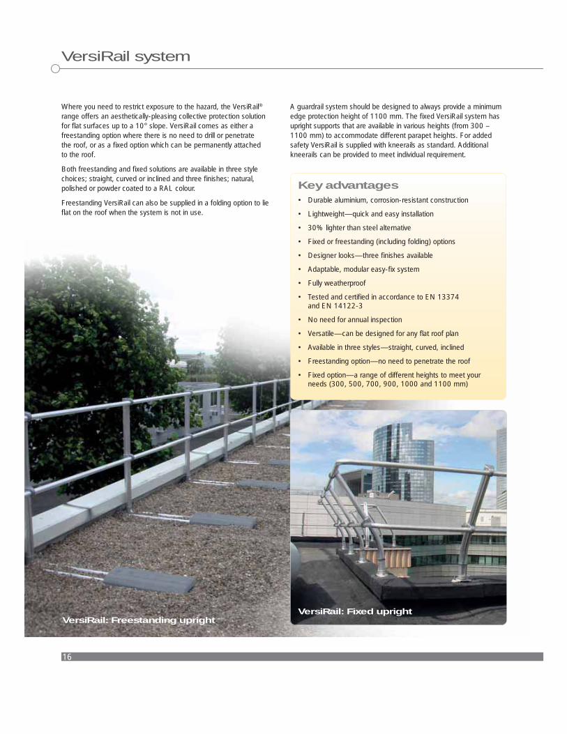
Where you need to restrict exposure to the hazard, the VersiRail®
range offers an aesthetically-pleasing collective protection solution for fl at surfaces up to a 10° slope. VersiRail comes as either a freestanding option where there is no need to drill or penetrate the roof, or as a fi xed option which can be permanently attached to the roof.
Both freestanding and fi xed solutions are available in three style choices; straight, curved or inclined and three fi nishes; natural, polished or powder coated to a RAL colour.
Freestanding VersiRail can also be supplied in a folding option to lie fl at on the roof when the system is not in use.
Key advantages• Durable aluminium, corrosion-resistant construction
• Lightweight—quick and easy installation
• 30% lighter than steel alternative
• Fixed or freestanding (including folding) options
• Designer looks—three fi nishes available
• Adaptable, modular easy-fi x system
• Fully weatherproof
• Tested and certifi ed in accordance to EN 13374and EN 14122-3
• No need for annual inspection
• Versatile—can be designed for any fl at roof plan
• Available in three styles—straight, curved, inclined
• Freestanding option—no need to penetrate the roof
• Fixed option—a range of different heights to meet your needs (300, 500, 700, 900, 1000 and 1100 mm)
A guardrail system should be designed to always provide a minimum edge protection height of 1100 mm. The fi xed VersiRail system has upright supports that are available in various heights (from 300 – 1100 mm) to accommodate different parapet heights. For added safety VersiRail is supplied with kneerails as standard. Additional kneerails can be provided to meet individual requirement.
VersiRail: Freestanding uprightVersiRail: Fixed upright

17
ManSafe for Roofi ngVersiRail: System options
Straight uprightThis simple design fi ts in perfectly with the clean lines and contours of a building.
The straight upright system is particularly suitable for protection at access points and demarking walkways.
Curved uprightWhilst providing the primary function of collective protection,the curved upright system compliments the design of a building.
This solution also keeps people further from the roof edge, providing a greater level of safety.
Straight upright system with:
1) Slab mounting plate
2) Wall mounting plate
3) Z-type mounting plate
4) Parapet mounting plate
Curved upright system with:
1) Slab mounting plate
2) Wall mounting plate
3) Z-type mounting plate
4) Parapet mounting plate
74 mm
1150 mm
1310 mm
100 mm
600 mm 185 mm
254 mm
1. 2. 3. 4.
1. 2. 3. 4.600 mm185 mm
1150
mm
645
mm
254
mm
100
mm
1310 mm
172
mm
440 mm

18
VersiRail: System options
Inclined uprightThis variation is inclined at 20°, which adds to the aesthetics of the system whilst making the system less visible from ground level. The result is better integration of VersiRail into the building design.
Freestanding foldingWhen collective protection is not being used, the folding uprights of this variation lie fl at and are concealed when viewed from ground level, combining safe with architectural aesthetics.Available in straight, curved or inclined styles.
Inclined upright system with:
1) Slab mounting plate
2) Wall mounting plate
3) Z-type mounting plate
4) Parapet mounting plate
315 mm10
0 m
m
1310 mm
1150
mm
185 mm 600 mm
172
mm
1. 2. 3. 4.
254
mm
100
mm
00mm
00m
m00
mm
m225
4m
m225
mm
600 mm185 mm
1150
mm
1310 mm
172
mm
75 mm

19
ManSafe for Roofi ngVersiRail: System components
Ancillary itemsVersiRail is exceptionally fl exible in its application through modular easy-fi x components allowing a wide range of confi gurations.
Fixing optionsThere are a number of brackets available for fi xing on or to parapet walls using either M10 or M12 bolts. These fi xings should also be chemically sealed where possible. It is essential to check the suitability of material that the fi xed VersiRail is to be installed on.
Corner sections
Where a change in system direction is required a standard 90° corner section can be supplied, or specifi c corner sections of between 45° to 175° can be made to order.
Access gate
Where VersiRail prevents access to a fall hazard such as a roofl ight or trap door, but access may be needed for maintenance, the access gate can provide trained personnel controlled access to these areas.
Slab mounting plate (200, 250 or 300 mm high)
Wall mounting plate (open option available)
Z-type mounting plate Parapet mounting plate
Closure bends
In situations where VersiRail needs to terminate and cannot be attached directly to a structural element, a closure bend can be specifi ed. This same part can be incorporated into a length of system to designate a safe entry/exit point.
Additional counterweights
Slab mounting plate (200, 250 or 300 mm high)
Connecting elements
T-Junctions, 45 – 45 corner sections and junction parts are all available to accommodate all system layouts.
Toeboard
On rooftops or surfaces where there is no parapet at the fall edge (or a parapet of less than 100 mm high) a toeboard can be affi xed to the base of the VersiRail.
Latchways plc, Hopton Park, Devizes, Wiltshire, SN10 2JP, England
Tel: +44 (0)1380 732700 Fax: +44 (0)1380 732701
Email: [email protected] Website: www.latchways.com
7A-V4-09/11
ManSafe®, WalkSafe®, VersiRail® and Constant Force® are registered trademarks of Latchways plcTransfastener™ is a trademark of Latchways plc