SECTION XII WASTEWATER CONVEYANCE SYSTEMS Subsection Designation
22
SECTION XII WASTEWATER CONVEYANCE SYSTEMS TABLE OF CONTENTS Subsection Designation and Title Page No. A. Introduction 1 B. Conventional Gravity Flow Sewers 1 C. Small Diameter Effluent Sewers (SDES) 2 D. Vacuum Sewers 3 E. Low Pressure Sewers 4 F. Force Mains 8 G. Construction Practices for Sewers and Force Mains 10 H. Pump Chambers 10 1. General 10 2. Pumps 11 3. Slide Rails and Appurtenances 12 4. Float Switches. 12 5. Pump Control Systems 13 6. Pump Control System Enclosures 13 7. Pump Chamber Structures 14 8. Valves and Valve Chambers 17 9. Selection of Materials and Equipment 17 I. Infiltration and Inflow 17 J. References 20 Table of Figures Figure No. On or Following Page No. XII-1 Profile of Small Diameter Variable Grade Effluent Sewer (VGES) 5 XII-2 Idealized Vacuum Sewer System 6 XII-3 Pump Chamber – Plan View 18 XII-4 Pump Chamber – Section Through Pump Chamber 19
Transcript of SECTION XII WASTEWATER CONVEYANCE SYSTEMS Subsection Designation
SECTION XII WASTEWATER CONVEYANCE SYSTEMS
TABLE OF CONTENTS
Subsection Designation and Title Page No. A. Introduction 1 B. Conventional Gravity Flow Sewers 1 C. Small Diameter Effluent Sewers (SDES) 2 D. Vacuum Sewers 3 E. Low Pressure Sewers 4 F. Force Mains 8 G. Construction Practices for Sewers and Force Mains 10 H. Pump Chambers 10
1. General 10 2. Pumps 11 3. Slide Rails and Appurtenances 12 4. Float Switches. 12 5. Pump Control Systems 13 6. Pump Control System Enclosures 13 7. Pump Chamber Structures 14 8. Valves and Valve Chambers 17 9. Selection of Materials and Equipment 17
I. Infiltration and Inflow 17 J. References 20
Table of Figures
Figure No. On or Following Page No. XII-1 Profile of Small Diameter Variable Grade Effluent Sewer (VGES) 5 XII-2 Idealized Vacuum Sewer System 6 XII-3 Pump Chamber – Plan View 18 XII-4 Pump Chamber – Section Through Pump Chamber 19
Section XII, Page 1 of 21
SECTION XII WASTEWATER CONVEYANCE SYSTEMS
A . Introduction This section provides an overview of the various means of conveying wastewater from its point(s) of origin to and through the various pretreatment facilities and from such facilities to the subsurface wastewater absorption system (SWAS), and to discuss some of the important parameters that affect the design, construction, operation and maintenance of such systems. Gravity flow sanitary sewers predominate in the systems that serve to collect wastewater and deliver it to centralized wastewater treatment facilities from which the treated effluent is discharged to surface water bodies or the land surface. Gravity flow systems are also used to convey wastewater to and within onsite wastewater renovation systems that ultimately discharge pretreated wastewater to a SWAS. However, alternate types of conveyance systems are often needed to meet specific site restraints and overall onsite wastewater renovation system (OWRS) design requirements. Alternate types of wastewater conveyance systems include:
• Small Diameter Effluent Sewers (SDES) Small diameter minimum grade (MGES) Small diameter variable grade (VGES)
• Vacuum Sewers, including vacuum pump stations and appurtenances • Pumped Systems
Low Pressure (LP) Sewers Force Mains
Pumping Stations and Chambers
B. Conventional Gravity Flow Sewers Conventional gravity sewers are the most common wastewater conveyance systems. Since they normally convey raw wastewater, they are installed on a slope sufficient to obtain a minimum velocity (≥ 2 ft/sec.) to prevent excessive deposition of solids. When a continuous downward slope sufficient to maintain the minimum velocity cannot be obtained, and tunneling is not a viable option, pump (lift) stations must be used to convey the wastewater over topographic high points to where a continuous downward slope can again be attained. Because they convey raw wastewater containing varying sizes of solids, conventional gravity flow sewers are usually restricted to pipe sizes of 8” or larger, although 6” diameter pipes are acceptable for short lengths of sewers serving a small OWRS. Manholes are required at points when the gravity sewers change pipe size, grade, horizontal direction, and generally at intervals ≤ 400 ft for purposes of periodic inspection and cleaning of the sewers. The main advantages of gravity sewers are the high flow capacities that can be accommodated and the minimum need for mechanical devices that require constant maintenance. However, there are several disadvantages to using gravity sewers. Infiltration and inflow (I&I) entering the gravity sewer system through the manholes and pipe joints increases the total wastewater flow. I&I can be largely controlled using modern materials and construction methods and watertight manhole covers. However, eventually, some I & I can be expected to occur as the system ages and the many pipe and manhole joints begin to deteriorate. Poorly constructed and deteriorated joints can also contribute to
Section XII, Page 2 of 21
contamination of the ground water by untreated wastewater leaking out of the sewers. Other disadvantages include: (1) their high capital cost, particularly in areas of high water tables, extensive subsurface rock formations, or unstable soil conditions, (2) the need to maintain a minimum pipe slope may require deep excavations, which often places the sewers well below the normal or seasonal high water table, thus increasing the risk of ground water infiltration, (3) increased potential for infiltration due to larger and more numerous pipe joints than other types of sewers, and (4) little flexibility in the location of gravity sewers. Design and construction of gravity sewers should conform to the applicable sections of Chapter 2 - Sanitary Sewers/Collection Systems in the New England Interstate Water Pollution Control Commission (NEIWPCC) publication TR-16.
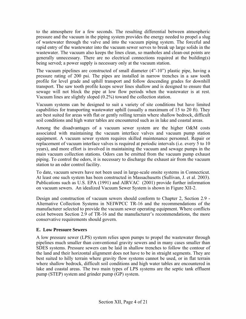
C. Small Diameter Effluent Sewers (SDES) Small diameter effluent sewers can be used to convey septic tank effluent to an OWRS. Two types of SDES systems are used. These include the variable grade effluent sewer (VGES) and the minimum grade effluent sewer (MGES). A septic tank equipped with an effluent screen will remove settleable solids and a large percentage of suspended solids from raw wastewater. Therefore, the concern for maintenance of a minimum velocity to avoid clogging of a SDES system is not as great as in the case of a conventional gravity sewer system. Plastic piping (e.g. polyvinyl chloride, or PVC) is used for SDES systems because of the corrosive effects of septic tank effluent. A variable grade effluent sewer (VGES) also conveys septic tank effluent by gravity. However, unlike a MGES, it generally follows the ground surface profile and is not required to maintain a continual downward slope. It also is not restricted to straight-line segments, as is the case of conventional gravity sewers. The force of gravity is still used to move the wastewater, but there can be some uphill sections and other sections in which the sewer flows full and is depressed below the hydraulic grade line. A depressed section will cause a backup in the sewer until sufficient flow surcharges the sewer, thus developing a hydraulic head sufficient to propel the effluent over the topographic high located downstream of the depressed section. As long as there is a net decrease in elevation from the upstream end to the downstream end of the VGES, the effluent will reach the downstream end despite any negative grade in the system. The concept is similar to that of an inverted siphon used in connection with conventional gravity sewer systems. The burial depth of the sewer only needs to be sufficient to prevent damage from superimposed loads and freezing problems. Because of the ability to reverse the slope of the pipe in many instances, the problems associated with deep excavations and costly excavation of subsurface rock required for conventional gravity sewers is greatly diminished. In addition, the smaller pipe sizes permit the use of narrower trenches. Thus, the cost of a VGES is usually significantly less than that of a conventional gravity sewer. A VGES should be constructed of plastic piping materials with cemented or other types of watertight joints that do not restrict the flow path in the piping. Cleanouts rather than manholes provide access to the sewer, are much less costly than manholes to construct and can be constructed with cemented or other types of watertight pipe joints and tightly sealed access caps to minimize I&I. Cleanouts generally consist of a pipe riser extending to the ground surface and connected to a standard “Y” fitting in the sewer via a 45-degree bend fitting. The riser is provided with a secure watertight cap.
Section XII, Page 3 of 21
VGES systems are best suited for use in moderately rolling terrain. The advantages of variable grade effluent sewers include less costly construction, the ability to avoid obstacles, the ability to design for future increases in flow without concern for minimum velocities due to low initial flows, and less I&I than conventional gravity sewers. The disadvantages include the need to provide odor control facilities due to the conveyance of anaerobic septic tank effluent that can emit odorous gases under turbulent flow conditions, the need to protect against the corrosive effects of septic tank effluent, and the potential difficulty in clearing of blockages. It is also necessary to provide air release valves at the high points and blow-offs at low points and these can also emit odors. For buildings in very flat or low lying areas that are below the hydraulic grade line of the VGES, a STEP system may be necessary to deliver the wastewater to the VGES. A profile of a VGES is shown in Figure XII-1, with dwelling No. 15 requiring a lift station (e.g. STEP system) in order to discharge the wastewater to the VGES. A MGES system is similar to a conventional gravity sewer system except that the pipe sizes can be smaller and the minimum design velocities (at flow depths of full or 1/2 full) can be in the range of 1 to 1.5 ft./sec. Similar to a VGES, the burial depth of the sewer only needs to be sufficient to prevent damage from superimposed loads and freezing problems, but must also be designed to maintain the minimum grades required. A disadvantage is the need to provide manholes, which are not required for VGES systems. Other disadvantages are similar to those of VGES, including the need to provide odor control facilities and to protect against the corrosive effects of septic tank effluent. The cost savings obtained by use of a MGES system are not as great as those resulting from use of a VGES. For both VGES and MGES systems, careful estimates of flow rates are required because of the smaller pipe diameters that do not provide the reserve capacity normally available in conventional gravity sewer systems. Also, as is the case wherever plastic piping is installed below ground, a means must be provided for locating the piping for maintenance and repair purposes. This can be done by installing magnetic tracing tape in the trench above the piping and by maintaining accurate as-built records of piping location. The use of either a VGES or MGES system requires a program for septic tank pumping and maintenance. Guidance for design of VGES and MGES is given in publications listed in the references at the end of this section.
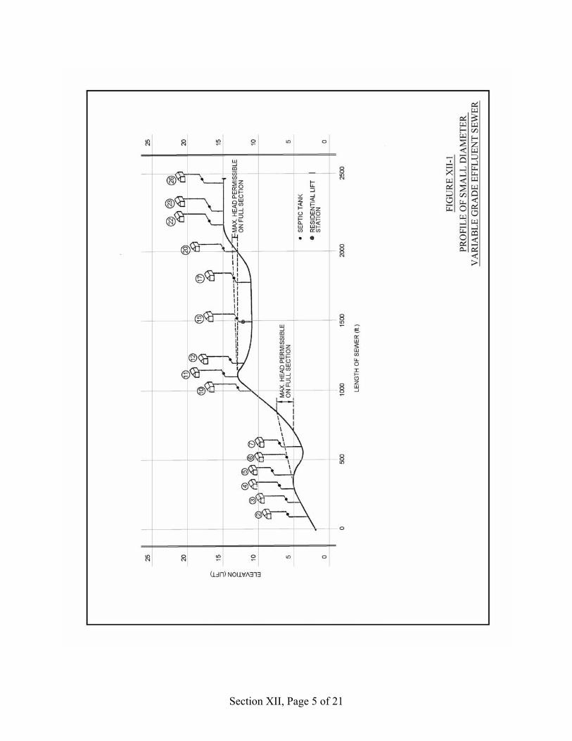
D. Vacuum Sewers A vacuum sewer system makes use of differential air pressure to convey the wastewater. The system includes a vacuum/gravity interface valve installed in a raw wastewater-receiving sump at each point of entry into the system, a collection piping system operating under negative air pressure (vacuum), and a centralized vacuum pump station containing a sealed collection tank, vacuum pumps and wastewater pumps. The vacuum created in the sealed collection tank by the vacuum pumps provides the force required for conveying the wastewater. Wastewater reaching the sealed collection (vacuum) tank via the vacuum piping system is then pumped from the tank into a pressurized pipeline (force main) that conveys the wastewater, either directly or via another conveyance system, to a treatment facility. The interface valve in the receiving sump is normally closed so as to maintain the vacuum in the piping downstream of the valve. Wastewater flows through the building sewer by gravity to the receiving sump that is normally installed underground. When the wastewater collected in the sump reaches a predetermined level, the interface valve opens
Section XII, Page 4 of 21
to the atmosphere for a few seconds. The resulting differential between atmospheric pressure and the vacuum in the piping system provides the energy needed to propel a slug of wastewater through the valve and into the vacuum piping system. The forceful and rapid entry of the wastewater into the vacuum sewer serves to break up large solids in the wastewater. The vacuum also keeps the lines clean, so manholes and clean-out points are generally unnecessary. There are no electrical connections required at the building(s) being served; a power supply is necessary only at the vacuum station. The vacuum pipelines are constructed of small diameter (4”-10”) plastic pipe, having a pressure rating of 200 psi. The pipes are installed in narrow trenches in a saw tooth profile for level grade and uphill transport and follow descending grades for downhill transport. The saw tooth profile keeps sewer lines shallow and is designed to ensure that sewage will not block the pipe at low flow periods when the wastewater is at rest. Vacuum lines are slightly sloped (0.2%) toward the collection station. Vacuum systems can be designed to suit a variety of site conditions but have limited capabilities for transporting wastewater uphill (usually a maximum of 15 to 20 ft). They are best suited for areas with flat or gently rolling terrain where shallow bedrock, difficult soil conditions and high water tables are encountered such as in lake and coastal areas. Among the disadvantages of a vacuum sewer system are the higher O&M costs associated with maintaining the vacuum interface valves and vacuum pump station equipment. A vacuum sewer system requires skilled maintenance personnel. Repair or replacement of vacuum interface valves is required at periodic intervals (i.e. every 5 to 10 years), and more effort is involved in maintaining the vacuum and sewage pumps in the main vacuum collection stations. Odors can be emitted from the vacuum pump exhaust piping. To control the odors, it is necessary to discharge the exhaust air from the vacuum station to an odor control facility. To date, vacuum sewers have not been used in large-scale onsite systems in Connecticut. At least one such system has been constructed in Massachusetts (Sullivan, J. et al. 2003). Publications such as U.S. EPA (1991) and AIRVAC (2001) provide further information on vacuum sewers. An idealized Vacuum Sewer System is shown in Figure XII-2. Design and construction of vacuum sewers should conform to Chapter 2, Section 2.9 - Alternative Collection Systems in NEIWPCC TR-16 and the recommendations of the manufacturer selected to provide the vacuum sewer operating equipment. Where conflicts exist between Section 2.9 of TR-16 and the manufacturer’s recommendations, the more conservative requirements should govern.
E. Low Pressure Sewers A low pressure sewer (LPS) system relies upon pumps to propel the wastewater through pipelines much smaller than conventional gravity sewers and in many cases smaller than SDES systems. Pressure sewers can be laid in shallow trenches to follow the contour of the land and their horizontal alignment does not have to be in straight segments. They are best suited to hilly terrain where gravity flow systems cannot be used, or in flat terrain where shallow bedrock, difficult soil conditions and high water tables are encountered in lake and coastal areas. The two main types of LPS systems are the septic tank effluent pump (STEP) system and grinder pump (GP) system.
Section XII, Page 5 of 21
Section XII, Page 6 of 21
Section XII, Page 7 of 21
The STEP system consists of pump chambers that accept the discharge from septic tanks, which is largely free from settleable solids and a high percentage of suspended solids. Therefore, the pumps do not have to have the large solids handling ability of raw wastewater pumps. They are invariably of the submersible, electrically driven centrifugal type, operating under low to moderate hydraulic head conditions and are equipped with level sensing controls to actuate the pumping cycles. The pumps discharge the septic tank effluent into a completely pressurized piping system and thus infiltration through pipe joints is not a concern. In order for a STEP system to be effective, the septic tank(s) must be watertight. A septic tank effluent pumping system (STEP) is often used for pressure distribution of pretreated wastewater to a SWAS and is also the predominant type of system used in conveying septic tank effluent to an enhanced pretreatment facility. Plastic piping is invariably used to resist the corrosive effects of the septic tank effluent. The piping normally consists of solvent welded rigid plastic pipe, or piping fabricated from long coils of flexible plastic (e.g.: polyethylene) pipe. The pumps must also be of corrosion resistant construction and electrical controls must be designed for corrosive and potentially explosive environments. Further information on pumping systems is given in the following subsection. Similar to conditions in SDES systems, septic tank effluent in the STEP system will release odors when turbulent conditions occur, for example, if the effluent is allowed to drop into a manhole or pumping chamber. Turbulent conditions can largely be avoided by use of drop pipes to convey the effluent to below the water level in the receiving structures. Odor problems can also occur via escape of the odorous gases through the pump chamber ventilation system. The simplest method of controlling such odors is by absorption of the malodorous gases released from the vents in soil absorption beds (biofilters). As in the case of VGES and MGES systems, careful estimates of flow rates are required for proper determination of the pumping capacity required and design of the small diameter pressure piping. Grinder pump (GP) systems consist of electrically driven pumps equipped with mechanisms for grinding the solids in the raw wastewater into particles small enough to be pumped through small diameter pressure piping systems. Grinder pumps eliminate the necessity to periodically pump a septic tank at each building served by a STEP system and the corrosion and odor problems associated with STEP systems are largely avoided. As is the case for STEP systems, air release valves are required at high points in the pressure piping system. However, there are disadvantages associated with GP systems. GP systems require more O&M than the various types of gravity sewer systems and the STEP system. Since they carry solids, a minimum velocity of 2 ft./sec. is required to maintain solids in suspension and a minimum velocity ≥ 2.5 ft./sec. is required to re-suspend solids that have settled in the pipelines during no-flow periods. In addition, the grinding mechanisms need periodic maintenance and greater inspection frequencies than STEP systems. Where GP systems are permitted to discharge to septic tanks in onsite wastewater renovation systems, the tanks must be specially designed to mitigate the adverse effects of receiving wastewater containing a slurry of small ground up solids mixed with fats, oil and grease (FOG). These adverse effects create difficulty in the separation of the solids
Section XII, Page 8 of 21
from the wastewater. A scum layer deeper than usually found in a septic tank may also develop because of the film of FOG coating the ground solids. Mitigation of these effects will involve larger tank volumes and enhanced provisions for baffling of the incoming flow to avoid stirring of the tank contents that can result in rapid clogging of the septic tank effluent filter. In general, pumping wastewater into septic tanks should be avoided because of the adverse effects on the relatively quiescent conditions required in the septic tank. The Department will normally not approve of a system that involves pumping wastewater into a septic tank unless convinced that special conditions make it unavoidable and that special design features will be provided to insure satisfactory operation of the septic tank. Design and construction of LPS systems should conform to Chapter 2, Section 2.9 - Alternative Collection Systems in NEIWPCC TR-16 and the recommendations of the manufacturer selected to provide the grinder pump equipment. Where conflicts exist between Section 2.9 of TR-16 and the manufacturer’s recommendations, the more conservative requirements should govern. Guidance for design of LPS systems is also given in NSFC publications listed in the references at the end of this section.
F. Force Mains. Force mains used for onsite wastewater renovation systems normally convey pretreated wastewater from a pumping station or chamber and deliver it under pressure to downstream facilities. Design of force mains involves determination of:
• The type of material to be used (e.g. ductile iron, various plastic materials) for pipe, fittings and valves,
• Required minimum and desirable maximum velocities, • Normal operating pressures, • Hydraulic head loss due to friction losses and form losses at fittings and valves,
and • Pressure surges (water hammer) caused by rapid starting and stopping of the
pumps. Force mains are designed to maintain minimum velocities under all flow conditions. However, most of the solids in the wastewater that remains in the force main during no-flow conditions will settle out to the bottom of the piping. Where raw wastewater is being pumped, a minimum velocity of ≥ 3 ft./sec. is generally required to scour these solids and re-suspend them in the wastewater. Where pretreated wastewater is being pumped, the minimum velocity should be ≥ 2.5 ft/sec. Maximum velocities will depend on the design flow and selected pump capacities. Generally, velocities should not greatly exceed the required scouring velocity, since higher velocities require greater use of electrical power. However, this may not be possible where the design flows are significantly greater than initial flows. Pumping facilities will normally be equipped with duplex pumps, as discussed in the following subsection. Therefore, it is possible to design for a 2-ft./sec. velocity under initial flow conditions with a scouring velocity induced once a day by having both pumps operate simultaneously for a short period of time. This can be accomplished under time clock control. However, this complicates the control system of the pumps, as it requires overriding the system provided for alternating the operation of the pumps and may induce
Section XII, Page 9 of 21
velocities greater than the required scouring velocity, which may result in excessive flow rates causing problems at downstream facilities. Thus, using this method of insuring scouring velocities should be approached very carefully. The type of pipe material used is based on the nature of the liquid being pumped (corrosivity, grit content) and the anticipated pressures (normal and surge) that will be exerted on the pipe. Force mains used for conveying septic tank effluent should be constructed of pressure rated plastic pipe such as PVC and polyethylene (PE) because of the corrosive nature of the effluent. PVC pipe of the push-on gasketed type should conform to AWWA Standard C900 and associated fittings should conform to AWWA C907. Ductile iron fittings of the push-on gasketed type or mechanical joint type with interior epoxy coatings suitable for use in septic tank effluent environments are also available. Ductile iron pipe and fittings should conform to the applicable AWWA and ANSI standards for ductile iron pipe and fittings. Where gate valves are used, they should be of the single gate, rather than double-disc type, because of the possible fouling of the open spaces between the discs by solids contained in the wastewater. Resilient seated single gate type valves suitable for operating in the corrosive atmosphere created by septic tank effluent are available with bronze shafts and trim, elastomer coated gate seats and epoxy-coated bodies. These valves should conform to AWWA C509. Eccentric-type plug valves are also available for use in wastewater conveyance systems. PVC pipe conforming to ASTM standards for Schedule 40 and Schedule 80 PVC pipe and fittings conforming to ASTM standards for PVC fittings for such pipe are also suitable. Threaded joints should be avoided because of the possibility of threaded joints failing at the root of the threads due to bending stresses. For small diameter force mains, PVC ball valves are also suitable. Force mains used for conveying effluent from enhanced pretreatment processes can also be constructed of cement-lined ductile iron pipe and fittings. Joint restraints or concrete thrust blocks should be provided for all force main piping at changes in direction of the piping. Valves in force mains are normally used in either open or closed position, but may also be used for throttling pump flow in certain cases. However, resilient seated gate valves should not be used for pump throttling unless approved for such service by the manufacturer. When pumps are started or stopped, or valves are closed very quickly, a pressure surge (water hammer) condition occurs in the force main that can result in high stresses being applied to the piping that could cause pipe failure. For short, gradually rising force mains (<1,500 ft) of small diameter, with small static heads, typical for on-site wastewater conveyance situations, the surge pressures are usually not excessive. Slamming of the check valve on the discharge side of the pump will usually occur, depending upon the amount of the surge pressure. If a check valve should stick in the open position, the pump can reverse direction due to backflow, which is an undesirable condition. To prevent this from happening, check valves used on pump discharge piping should be of the resilient seated swing gate type with outside lever and weight or other types specifically designed for used in wastewater pumping systems.
Section XII, Page 10 of 21
Cushioned type outside lever and weight type check valves equipped with hydraulic or pneumatic cylinders are available that mitigate against banging of the valve. For long force mains, detailed investigation of the pressure surges that may develop is imperative and means must be taken to alleviate such conditions, such as the installation of a surge control device, soft start motor starters, or variable speed pumping systems. An interesting discussion on pressure surges in force mains is provided in Metcalf & Eddy (1981) and in the Uni-Bell Handbook (2001), and additional information may be found in other standard references on pressure flow. Design of force mains should conform to Chapter 2, Section 3.7 - Force Main in NEIWPCC TR-16 and the guidelines presented above. Where conflicts exist between Section 3.7 of TR-16 and the guidelines given above, the more conservative requirements should govern.
G. Construction Practices For Sewers and Force Mains Construction methods, including leakage testing, for sewers and force mains should conform to the applicable requirements of NEIWPCC TR-16, guidelines and recommendations of the pipe manufacturers and any association of manufacturers for the type of piping material being used, Federal, State and local safety codes, and good practices of the construction industry. Where conflicts exist between NEIWPCC TR-16 and the guidelines and codes referenced above, the more conservative requirements should govern. Except as noted below, wherever plastic piping is installed below ground a magnetic tracing tape should be installed in the trench to permit locating the piping for maintenance, repair or replacement. Warning (marking) tape should be used in lieu of magnetic tracing tape for all other types of buried piping.
H. Pump Chambers
1. General Virtually all pumping stations and chambers (hereinafter referred to collectively as pump chambers) used as part of on-site wastewater renovation systems utilize pumps of the submersible, electrically driven, centrifugal type, installed in precast concrete structures that also serve as wet wells. In some cases, durable, long lasting materials other than precast concrete may be used for the pump chambers. Unless otherwise permitted by the Department, the pumping system should include at least two pumps of equal capacity (duplex type), arranged for operating on alternate duty cycles so as to equalize the pumping duty and be of the slide-rail mounted lift-out type. Submersible pumps should be maintained in a submerged condition at all times so as to preclude formation of a vortex at the pump suction inlet that can lead to air binding or a reduction in pumping efficiency. Information should be obtained from the pump manufacturer as to the depth of submergence required. The control systems for these pumping facilities can be either installed inside a structure or at outdoor locations adjacent to the pump chamber. Pump check valves may be installed on the pump discharge piping within the pump chamber, if they can be lifted out with the pump, or in valve chambers installed in close proximity to the pump chamber. Pump isolation valves should always be installed outside of the pump chamber to avoid
Section XII, Page 11 of 21
having to enter the chamber for operation and maintenance purposes. Pump isolation valves may be installed in a separate valve chamber (along with check valves) or as direct burial valves equipped with valve boxes. Where drain back of piping downstream of the pump chamber is required after a pumping cycle, and check valves are installed within the pump chamber, a drain hole fitted with a long brass nipple and brass elbow angled downward should be provided in the vertical discharge piping, downstream of the check valves, where it will be least subjected to clogging. The direction of the discharge from the drain hole fittings should be such as will not interfere with normal operation and maintenance activities. 2. Pumps Pumps should be suitable for long-term operation and be designed specifically for pumping the particular type of wastewater and for operation under the most severe ambient conditions in which they will be operated. Pumps used for pumping septic tank effluent should be of the explosion proof type, unless they remain fully submerged in the wastewater at all times. While liquid level controls can ostensibly be designed to provide submergence of the pumps, there is always the possibility that these controls may malfunction. Therefore, the safest procedure is to provide pumps of explosion proof design whenever possible. Pumps of explosion proof design should be certified by the manufacturer for use in Class I, Division I, Group C and D hazardous locations as specified in the National Electric Code (NEC). Pumps used for pumping of effluent in and from enhanced pretreatment processes do not need to be explosion proof but should be designed to operate submerged at all times. Pumps should be capable of delivering the design flow at the total design head. The pumps should be non-overloading at any point on their characteristic curve and should not operate very close to their shut-off head. Each pump should be equipped with a submersible type oil-filled motor suitable for operation at the voltage and phases of the power supply source. Power cords should be long enough to extend to the full height of the pumping chamber and through the wall of the chamber to an outside mounted junction box. The motor should have heavy-duty ball bearings to support the pump shaft and take radial and thrust loads. Normally closed automatic reset thermostats connected in series should be embedded in adjoining phases of the stator windings and should be connected to stop the motor if the temperature of the winding exceeds the maximum permissible operating temperature. Pumps should be of double seal construction using two mechanical seals in tandem with an oil chamber between the seals. Seals should be readily commercially available from third party sources other than the pump and motor manufacturer. Wherever possible, the oil chamber between the seals should be fitted with a moisture sensing probe system to detect the entrance of moisture into the lower oil seal housing and provide an alarm to the pump control panel. The probe should activate a red seal failure light in the pump control panel. Wherever feasible, replaceable wear rings should be provided at the suction inlet and impellers should be statically and dynamically balanced and equipped with replaceable brass wear rings. An approved corrosion resistant coating should protect all surfaces coming into contact with wastewater other than bronze and stainless steel. The common motor pump shaft and all fasteners should be stainless steel.
Section XII, Page 12 of 21
Separate pump motor power and control cables, and the method of connecting these cables to the equipment being operated should be suitable for the atmosphere in which they will be located. Cable sizing should conform to NEC specifications for pump motors. Both power and control cords should include separate grounding conductors and strain relief mechanisms should be provided at all points of connection. 3. Slide Rails and Appurtenances There should be no need for personnel to enter the pump chamber in order to remove or re-install the pumps. Each pump, and attached check valve if provided, should be automatically connected to the discharge piping when lowered into place on a guide (slide) rail system, requiring no bolts, nuts or fasteners to effect leak proof sealing to the discharge connection. The pump, and attached check valve if provided, should be easily removed for inspection or service. A simple linear downward motion of the pump should accomplish sealing of the pumping unit to the discharge connection. The weight of the pump should be supported by and bear solely on the discharge base and not on the guide rails or chamber bottom. The slide rail system should be of non-sparking design and should be listed for explosion proof service when installed in pump chambers containing septic tank effluent. Slide rails and appurtenances should be manufactured of materials that will have a long-term resistance to corrosion and be of sufficient strength to bear all of the loads imposed on them. Slide rail top and intermediate support brackets should be adjustable to permit accurate vertical alignment of rails. A corrosion resistant lifting chain of adequate strength and length to permit raising and lowering of pumps should be provided. All hardware should be stainless steel.
4. Float Switches Sealed float-type switches should be supplied for pump control and alarm signals. The switches should be sealed in a leak-proof solid polyurethane float for corrosion and shock resistance. The support cable for each float switch should have a heavy neoprene jacket suitable for the environment in which it will be used and should be equipped with a weight attached to the cable to hold the float in place in the wet well. The weight should be positioned above the float to prevent sharp bends in the cord when the float operates under water. All float switches should be supported only by cables attached to a wiring support fixture. Three float switches should be provided to control liquid level in the wet well: one for stopping either or both pumps, one for lead pump start, and one for lag pump start. Two additional float switches should be provided for alarms; one for low liquid level alarm and one for high liquid level alarm. Wiring supports with cable grip holders should be provided near the top of the pump chamber for the pump cables and the control and float switch cables. The supports should be easily accessible from the access hatch of the pump chamber and should provide for easy adjustment of cables to the desired switch operating levels without having to enter the pump chamber. As an alternative to float switches, pressure transducer type switches designed for service in wastewater systems can also be used.
Section XII, Page 13 of 21
5. Pump Control Systems The control system for the wastewater pumps should contain: • a main circuit breaker designed to disconnect all power conductors, • individual circuit breakers for each pump, • magnetic motor starters, • three pole ambient compensated quick trip overload relays, • MANUAL-OFF-AUTOMATIC selector switches, • automatic lead-lag pump alternation, with automatic hold feature to allow continued
operation of a single pump if the other pump has failed. • lead pump start, lag pump start, pump stop, low level alarm and high level alarm level
sensing via float switches, • Pump run lights, • alarm lights for high liquid level and low liquid level in the pump chamber, • a seal failure alarm light for each pump, • an over-temperature light for each pump with manual light reset, • an elapsed time meter and amp meter for each pump, • auxiliary contacts for remote high level, low level and loss of power alarms, • a strip heater to prevent accumulation of condensed moisture within the panel, • lightning/power surge arrestors, and • Legend plates, clearly labeled, durable, and securely fastened in position, to identify
all switches, meters, run lights and alarm lights. A main circuit breaker and separate auxiliary circuit breakers should be provided for alarm and control circuits. Control power should be a maximum of 120 volts. Intrinsically safe relays should be provided for operation of all float switches. The alternation system should provide for alternate pump operation on each successive cycle, and include an override circuit to start both pumps if the level rises in the pump chamber or to start the second pump if one pump fails. An alarm switch should be provided for on-off, acknowledge, reset and test. Auxiliary dry contacts should be provided to send signals for high liquid level, low liquid level and loss of power alarms to a remote monitoring system via a dialing alarm monitor or other suitable equipment. The remote monitoring system shall be capable of alerting personnel assigned to providing a rapid response to, and correction of, any malfunction at the pump chamber. Seal failure and over-temperature alarms may be indicated by local alarm lights mounted in the control panel if frequent inspections of the pump chamber are conducted. Audible and visual alarm facilities, suitable for outdoor use, should be provided that will be actuated by any of the alarm indications provided to the remote alarm monitoring system. The alarm facilities should be mounted in a conspicuous location where the alarms can be heard and seen by system users to warn of pump failures. An inside mounted alarm bell and light should also be provided at a conspicuous location within the premises being served, unless an inside mounted pump control panel is similarly located. 6. Pump Control System Enclosures The pump control enclosure should conform to the NEMA 250 standards for the atmosphere in which it will be located and be of sufficient size to accommodate all pump controls. The selected manufacturer of the enclosure should be advised of the ambient atmosphere to which the enclosure will be exposed.
Section XII, Page 14 of 21
Pump control enclosures should conform to one of the following NEMA Types. • Type 1, suitable for indoor use in dry locations. • Type 2, suitable for indoor use where the enclosure may be subject to dripping and
light splashing of liquids. • Type 3R, suitable for outdoor use, where the enclosure may be subject to rain, sleet
and snow and the external formation of ice on the enclosure. • Type 4, suitable for outdoor use, where the enclosure may be subject to rain, sleet,
snow, wind-blown dust, splashing water and hose-directed water and the external formation of ice on the enclosure.
• Type 4X, suitable of indoor and outdoor use, where the enclosure may be subject to the same conditions as a Type 4 enclosure and is also subject to a corrosive atmosphere.
• Type 7, suitable for indoor use in hazardous locations classified as Class I, Division 1, Groups A, B, C, or D as defined in NFPA 70 (National Electric Code).
• Type 8, suitable for indoor and outdoor use in hazardous locations classified as Class I, Division 1, Groups A, B, C, or D as defined in NFPA 70 (National Electric Code).
The control enclosure should be provided with a full dead-front locking type outer door and all switches, lights, meters, etc. should be mounted on a hinged inner door. A schematic wiring diagram and overload heater chart should be displayed on the inside of the panel cover. The control panel and control enclosure should be completely assembled and pre-wired at the place of manufacture and should conform to IEEE, NEMA and National Electric Code design standards and requirements. All wiring should conform to NEMA wiring standards. Multi-colored circuits should be used within the control panel enclosure to facilitate troubleshooting. Solder-less type terminal blocks, with individually labeled wire terminals, should be provided for connection of power supply, motors and controls. All wiring should be multi-stranded and neatly bundled and color-coded. Both ends of all wires should be clearly numbered with permanent markers. The control panel should include all auxiliary devices such as relays, auxiliary contacts, interlocks, selector switches, etc., required to provide the specified functions.
7. Pump Chamber Structures Structures (e.g.: rectangular tanks, circular manhole sections) serving as wet wells housing submersible pumps should consist of precast reinforced concrete sections, complying with applicable provisions of ASTM C478, C890 and C913. The concrete should have a minimum compressive strength of 4000 psi at 28 days. Air entrained concrete should be used. Design of the pump chambers should include anti-floatation provisions to prevent dislocation by water pressure due to high water table conditions. Accurately cast rigid pipe sleeves with integral water stop should be cast into wall sections at the proper locations and elevations for connection of piping and electrical conduit to the pump chamber. The sleeves should be of proper size to accommodate piping and conduit and the materials used to provide a watertight seal of the pipe to the structure.
Section XII, Page 15 of 21
Guidance for flexible, watertight connection of piping to concrete structures is also provided in ASTM C923-02. Sealing of electrical power and float cables in conduits at Class I, Division I, Group C and D hazardous locations should be made as specified in the National Electric Code (NEC). All exterior surfaces, except where above grade or in contact with concrete access risers, masonry manhole frame risers, or anti-flotation collars, should receive a damp-proof coating. All joints should be sealed with a self-sealant butyl based rubber gasket or other approved sealant material. Precast concrete access risers extending from the top of the structure to an elevation at least several inches above finished grade should be provided for removal and maintaining the pumps and for inspection of the pumping chamber. Risers for pump removal shall be of rectangular cross-section equipped with lockable hinged access covers. Other risers provided for chamber inspection and cleaning can be of circular cross-section equipped with manhole frames and covers that can be secured in such manner as to prevent vandalism. They should comply with the same manufacturing and construction requirements set forth above for the main pump chamber. Each pump access riser should be complete with a cast-in-place corrosion resistant (e.g. aluminum) access hatch frame and cover that will provide ample room for removing and replacing the submersible pumps. Risers should be cast and set level and plumb. All riser joints should be sealed in a manner similar to that used in sealing the pump chamber. Provisions should be made for securely attaching the riser to the top of the pump chamber. When grouting is complete, all grout surfaces should also be sealed with a damp-proof coating. Access hatch covers and frames should be fabricated of corrosion resistant material (e.g. aluminum) and should consist of single leaf or double leaf doors that open with spring assist to 90° and automatically lock in the open position with stainless steel hold open arms with aluminum release handles. Hatch doors should be designed to support the maximum load likely to be imposed and should be equipped with a lock and removable key and a non-corrodible lifting handle. Hold open arms incorporating enclosed stainless steel compression spring assists should be provided. Doors should be designed to close flush with the frame and rest on a built-in odor reducing neoprene gasket. All lifting handles and hinges shall be completely flush with the hatch covers and frame when in the closed position. Hinges and all fastening hardware should be stainless steel. All access hatch doors should be provided with safety anti-fall nets with stainless steel fastening hooks or other suitable anti-fall safety devices. The working volume (liquid volume between normal pump start and stop levels) for duplex pumping systems will depend upon the function of the pumping facilities. Where the pumps will be delivering wastewater to downstream pretreatment facilities, and other considerations do not control, the working volume should limit the pump cycles to six or less per hour in order to prevent overheating of the pump motor and excessive wear on the magnetic starter contacts. In this case, the minimum cycle time for single pump operation occurs when the inflow is exactly half the pumping capacity. Under this condition, the on and off times are equal. The cycle times are greater for the cases when the inflow is larger or smaller than half the pumping capacity.
Section XII, Page 16 of 21
This leads to the following formula for calculating minimum working volume (Metcalf & Eddy -1981):
Working Volume, V, in gallons, = 0.25 x (minimum pump cycle time*, in minutes) x (pump capacity, in gallons per minute).
* time between successive starts. Thus, if six cycles per hour are desired, the cycle time is 60 min./hour/6 cycles per hr. =10 minutes. Thus, the working volume = 2.5 x pump capacity.
It should be noted that the working volume could be reduced by half where a duplex pumping system contains identical pumps and where alternation is provided. However, consideration should be given to the circumstances that would prevail should one pump fail and an extended period of time is required for repair or replacement of the pump. In addition to establishing a minimum working volume, additional volume should be provided for proper pump submergence and for incremental settings of the various float switches. Generally, an increment of 6 inches should be provided between successive float actuation levels. Thus, the float switch that causes the lead pump to start should be set at the liquid level elevation established by the total of the working volume and the pump submergence volume. The high water alarm float switch should be set to actuate the alarm when the liquid level rises 6 inches above the lead pump start level. The lag pump switch should be set to start the lag pump when the liquid level rises 6 inches above the high water alarm level. The high water level should be such as not to cause a backwater condition in the wastewater inlet piping. Additional reserve volume should be provided in the pump chamber for emergency storage in incoming wastewater for a period of time sufficient for operating personnel to respond to a pumping station malfunction. A minimum of 4 hours of reserve volume should be provided. Where pump chamber malfunction is due to a power outage, and an emergency source of power cannot be made available within a 4-hour period, at least 24 hours of reserve volume should be provided. The Department may waive this requirement if it can be shown that the power outage will also result in interruption of wastewater flow from the source being served. Where the required reserve volume cannot reasonably be provided within the pump chamber, an emergency overflow should be provided to a temporary holding tank. Provision should be made for automatic return of the holding tank contents upon restoration of normal pumping operations. Where the pumping facilities are used for flow equalization, or recirculation, or for pressure distribution of pretreated wastewater to an SWAS, or for wastewater transfer between enhanced pretreatment facilities, the working volume will be dictated by such uses. However, the pump cycle times should always be checked to insure that excessive pump cycling will not occur. Where the submersible pumps serve to discharge pretreated wastewater to a SWAS, it is good practice to set the pumps on a concrete platform whose top is 12 inches above the bottom of the pump chamber. This will minimize any solids remaining in the wastewater that settle out in the pump chamber from being drawn into the pumped liquid and discharged to the SWAS. (Periodic inspection of the pump chamber and the removal of any accumulated solids deposits should be a regular part of the normal O&M procedures.)
Section XII, Page 17 of 21
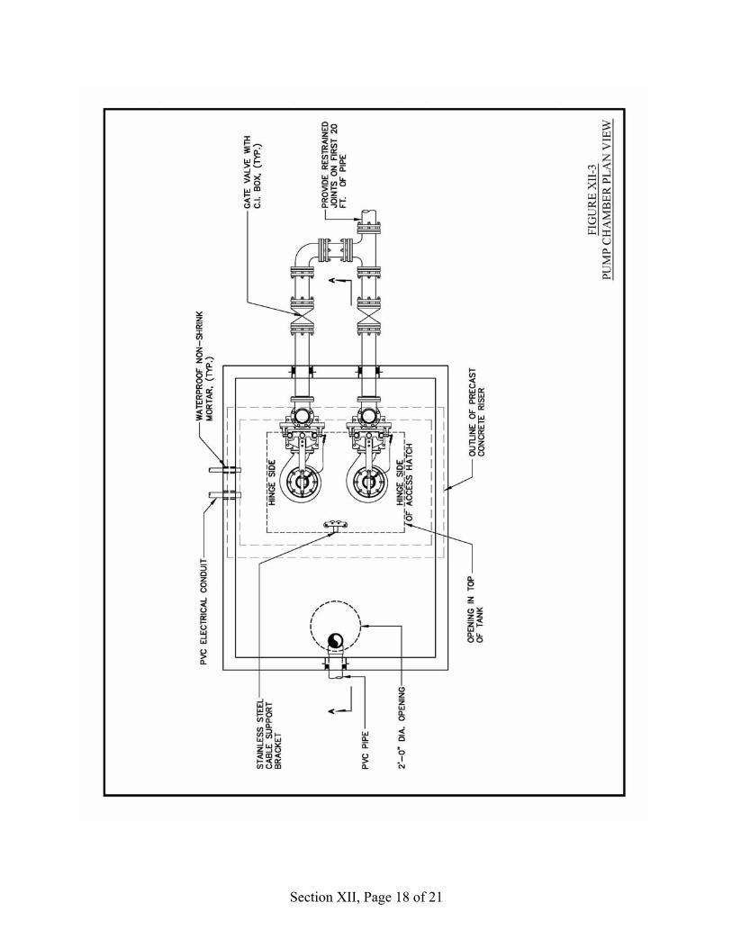
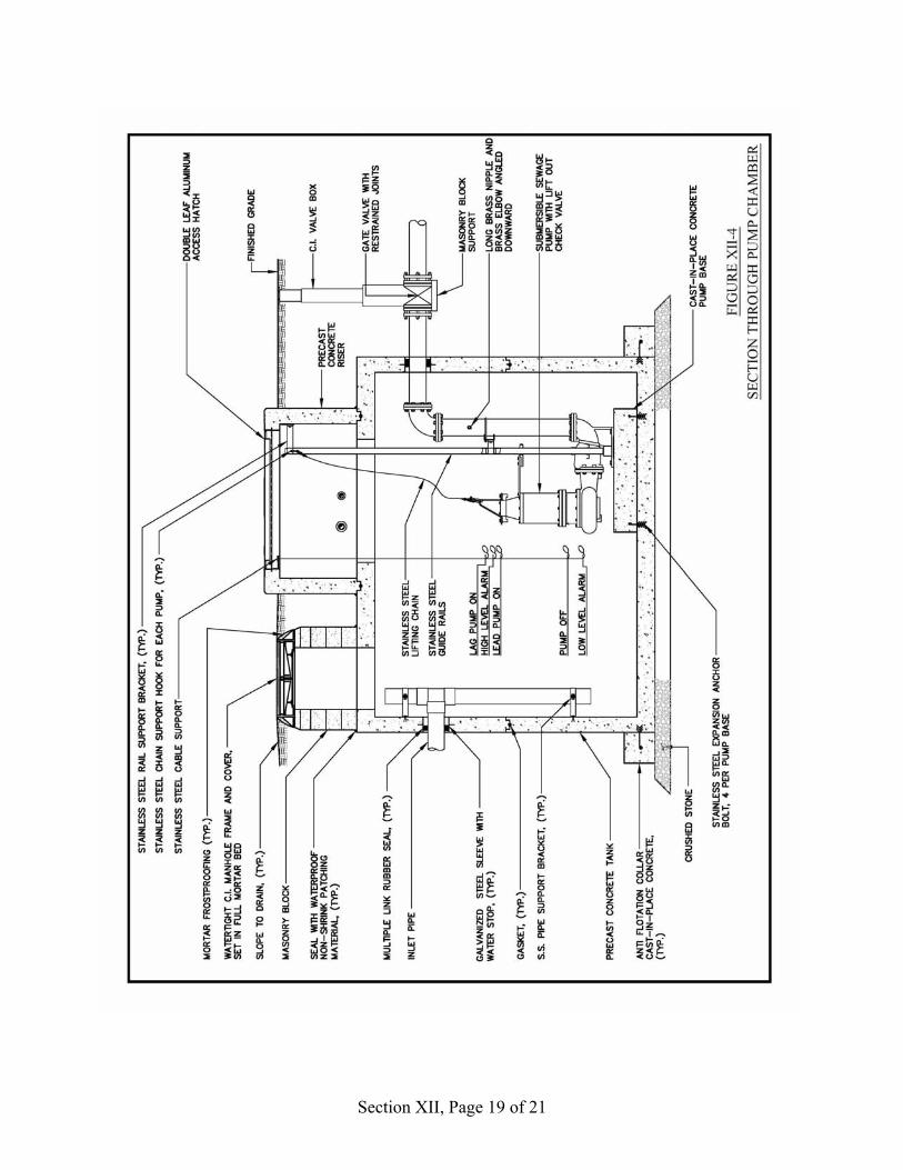
Where the wastewater received at a pumping chamber is corrosive in nature (e.g.: septic tank effluent), it should be discharged into the chamber below the low liquid level via a drop pipe to prevent splashing and release of corrosive gases. Provisions should also be made for passive ventilation of the pump chambers. Where septic tank effluent is being pumped, provisions should also be made for control of odors emanating from the ventilation piping. Either activated carbon canisters or biofilters can be used for odor control, with subsurface biofilters being preferred if there is adequate space available for their construction. 8. Valves and Valve Chambers All pump isolation valves should be installed outside of the pump station or chamber. They may be installed underground with valve boxes for access, or they may be installed in a valve chamber located adjacent to the pump station or chamber. Where check valves are not an integral part of the submersible pump lift-out mechanism, they should also be installed in a horizontal position in a valve chamber. Where drain back of the pressure piping after pumping has stopped is required, provisions must be made for draining the piping downstream of the check valves back to the pump chamber. The design and fabrication of the valve chamber and provisions for access to the valves should be equivalent to that of the pump chamber. Design of the valve chambers should include anti-floatation provisions to prevent dislocation by water pressure due to high water table conditions. Typical details for a pumping chamber with underground valves are shown in Figures XII-3 and XII - 4.
9. Selection of Materials and Equipment All materials, equipment, and the coatings applied to them, that are selected for use in wastewater conveyance systems should be certified by the manufacturer as being suitable for long-term heavy duty use in the environment in which they will be utilized.
I. Infiltration and Inflow Every effort must be made to reduce infiltration and inflow into the wastewater conveyance system, as any extraneous liquid can have an adverse and sometimes severe impact on pretreatment facilities and the ability of the SWAS to accomodate the increased discharge.
Section XII, Page 18 of 21
Section XII, Page 19 of 21
Section XII, Page 20 of 21
J. References IEEE Institute of Electrical and Electronic Engineers, Inc. Washington, D.C. AIRVAC 2001. AIRVAC Design Manual. AIRVAC, Inc. Rochester, IN. ANSI American National Standards Institute, NY, NY. ASTM C478. Latest Edition. Standard Specification for Precast Reinforced Concrete
Manhole Sections. American Society for Testing and Materials, West Conshocken, PA.
ASTM C890. Latest Edition. Standard Practice For Minimum Structural Design Loading for Monolithic or Sectional Precast Concrete Water and Wastewater Structures. American Society for Testing and Materials, West Conshocken, PA.
ASTM C913. Latest Edition. Standard Specification for Precast Concrete Water and Wastewater Structures. American Society for Testing and Materials, West Conshocken, PA.
ASTM C923. Latest Edition Standard Specification for Resilient Connectors Between Reinforced Concrete Manhole Structures, Pipes, and Laterals. American Society for Testing and Materials, West Conshocken, PA.
AWWA C 509. Latest Edition. AWWA Standard for Resilient Seated Gate Valves for Water Supply Service. American Water Works Association, Denver, CO.
AWWA C900. Latest Edition. AWWA Standard for Polyvinyl Chloride (PVC) Pressure Pipe, 4 Inches Through 12 Inches for Water Distribution. American Water Works Association, Denver, CO.
AWWA C907. Latest Edition. AWWA Standard for Polyvinyl Chloride (PVC) Pressure Fittings for Water, 4 Inches Through 8 Inches. American Water Works Association, Denver, CO.
Gidley, J.S. Undated. Case Study No. 13. Dexter, Oregon Minimum Grade Effluent Sewers. W. V. University, Morgantown, WV. Available from National Small flows Clearinghouse, Morgantown, WV.
Metcalf & Eddy, Inc. 1981 Wastewater Engineering: Collection and Pumping of Wastewater. Written and edited by G. Tchobanoglous. McGraw-Hill Book Company, NY, NY.
NEC NFPA 70. National Electrical Code, Latest Edition. National Fire Protection Association. Quincy, MA
NEMA 1997 Enclosures for Electrical Equipment (1000 Volts Maximum. NEMA Standards Publication 250-97. National Electrical Manufacturers Association, Rosslyn, VA.
NEIWPCC TR-16 1998 Edition. Guides for the Design of Wastewater Treatment Works. New England Interstate Water Pollution Control Commission, Wilmington, MA.
Section XII, Page 21 of 21
J. References NSFC 1995. Variable Grade Effluent Sewer Design Program, Version 2 and User’s
Guide. WWSWDM79. National Small Flows Clearinghouse, WV Univ. Morgantown, WV.
NSFC Undated. Septic Tank Effluent Pump Pressure Sewer Systems Information Package. National Small Flows Clearinghouse, WV Univ. Morgantown, WV
NSFC Undated. Design Module Number 7. Low Pressure Sewer Systems. WWBLDM07. National Small Flows Clearinghouse, WV Univ. Morgantown, WV.
NSFC Undated. Alternative Sewers Operation and Maintenance Special Evaluation Project. WWWBLOM07. National Small Flows Clearinghouse, WV Univ. Morgantown, WV.
Simmons, J.D. and J.O. Newman. 1982. Design Workbook for Small-Diameter, Variable-Grade, Gravity Sewers. U.S. Department of Agriculture, Clemson, S. Carolina. Available from NSFC as publication WWBLDM13.
Sullivan, J.F., B. Harrington, S. Johnson, and K Bergman. 2003. Advent of Vacuum Sewers in New England. In: Proc. of 2003 Annual Conference of the New England Water Environment Association. Boston, MA Jan.26-29, 2003.
SWPA 1986 Submersible Sewage Pumping Systems Handbook. Submersible Wastewater Pump Association. Lewis Publishers, Inc. Chelsea, MI
Thrasher, D. 1987. Design and Use of Pressure Sewer Systems. Lewis Publishers, Inc. Chelsea, MI.
Uni-Bell Handbook 2001. Handbook of PVC Pipe - Design and Construction. The Uni-Bell PVC Pipe Association. Dallas, TX.
U.S. EPA 1988. Design Module Number 22. EPA Variable Grade Sewers Special Evaluation Project. U. S. Environmental Protection Agency, Municipal Facilities Branch, Technical Support Branch. Available from NSFC as publication WWPCDM22.
U.S. EPA 1991 Manual - Alternative Wastewater Collection Systems. EPA/625/1-91/024. Office of Research and Development, Cincinnati, OH and Office of Water, Washington, D.C.\
WEF 1986 Alternative Sewer Systems. Manual of Practice No. FD-12. Water Environment Federation. Alexandria, VA.
WEF 1999. Control of Infiltration and Inflow in Private Building Sewer Connections. Water Environment Federation. Alexandria, VA.